Embed Size (px)
Citation preview

Telegea Smart Hub, Hardware descriptionRev. B, 11/02/2019
Telegea Smart Hub
Hardware Description
Table of Contents1 Overview...........................................................................................................................................22 References.........................................................................................................................................43 Extension Modules............................................................................................................................54 Interface Description.........................................................................................................................6
4.1 Screw Terminal Block for Digital IO and Counters (Designator P9, P10 and P11)..................64.2 Micro USB Socket (Designator J2)...........................................................................................74.3 USB Socket (Host) (Designator J3)...........................................................................................74.4 Screw Terminal Block for RS485 Connection (Designator P7)................................................74.5 USB Socket (for Power Supply only) (Designator J1)..............................................................84.6 XBee compatible Expansion Socket (Designator P4/P5)..........................................................94.7 Display Connector (Designator P3).........................................................................................104.8 Extension Header for Wifi module (Designator P2)................................................................124.9 SO-DIMM Socket for Raspberry Pi Compute Module (Designator J11)................................124.10 Ethernet Socket (Designator J6)............................................................................................134.11 Debug Port Header (Designator P1)......................................................................................134.12 Generic Expansion Header (Designator P6)..........................................................................144.13 Sensor2/Relay (I2C)(Designator J5).......................................................................................154.14 Sensor Connector 1 (SPI) (Designator J4).............................................................................164.15 Screw Terminal Block for ADC inputs and M-Bus (Designator P15)...................................164.16 Jumper block for ADC channel configuration (Designator P14)..........................................174.17 Screw Terminal Block for DC Power (Designator P13)........................................................194.18 Extension socket for custom modules (Designator P8).........................................................19
5 Integrated components.....................................................................................................................215.1 I2C bus......................................................................................................................................215.2 Serial ports...............................................................................................................................215.3 Sensors.....................................................................................................................................215.4 User interface...........................................................................................................................22
1/22
Telegea Smart Hub, Hardware descriptionRev. B, 11/02/2019
1 Overview
The Telegea Smart Hub is an embedded electronical device. It is powered externally by low voltage.It connects to external sensors and other devices via dedicated interfaces and bus systems.Furthermore it features digital input/output connectors for on/off functions, status/pulse detectionand pulse counting. Several connectors are provided to add optional extension modules to extendthe devices functionality.
This revision of the document describes the revision R3C0 of the PCB.
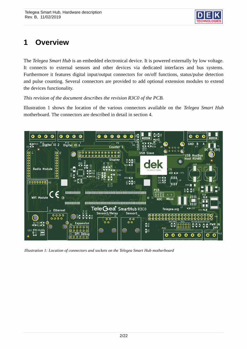
Illustration 1 shows the location of the various connectors available on the Telegea Smart Hubmotherboard. The connectors are described in detail in section 4.
2/22
Illustration 1: Location of connectors and sockets on the Telegea Smart Hub motherboard
Telegea Smart Hub, Hardware descriptionRev. B, 11/02/2019
Designator Brief DesciptionLink to Detailed
Description1 P11, Digital IO 2
Screw Terminals for Counters, Status signals and generic digital IO
Section 4.1, Page 62 P10, Digital IO 1
3 P9, Counter 1
4 J2, USB Slave USB Socket (Slave/Boot) – for updating device SW Section 4.2, Page 7
5 J3, USB Host USB Socket (Host) – for USB devices such as Flash Drives or relay cards
Section 4.3, Page 7
6 P7, RS485 Screw Terminals for Modbus RS485 Interface Section 4.4, Page 7
7 J1, DC IN USB Socket – Power Supply only Section 4.5, Page 8
8 P4 + P5, XBee Module X-Bee compliant Expansion Socket Section 4.6, Page 9
9 P3, Display Connector for LCD Touch Screen Section 4.7, Page 10
10 P2, Wifi Module Extension Socket for Wifi Module Section 4.8, Page 12
11 P12, Compute Module Socket for Raspberry Pi Compute Module Section 4.9, Page 12
12 J6, Ethernet RJ45 Ethernet Socket Section 4.10, Page 13
13 P1, DPI Debug Debug Port Interface Section 4.11, Page 13
14 P6, Expansion Expansion Socket Section 4.12, Page 14
15 J5, Sensor2/Relay Sensor / Relay card Connector (I2C) Section 4.13, Page 15
16 J4, Sensor1 Sensor Connector (SPI) Section 4.14, Page 16
17 P15, ADC / Mbus Screw Terminals for ADC inputs and M-Bus Section 4.15, Page 16
18 P13, AC IN Screw Terminals for AC Power Section 4.17, Page 19
19 P8 Extension socket for custom modules Section 4.18, Page 19
20 P14 Jumper block for ADC channel configuration Section 4.16, Page 17
3/22
Telegea Smart Hub, Hardware descriptionRev. B, 11/02/2019
2 References
[1] USB 2.0 specificationhttp://www.usb.org/developers/docs/usb20_docs
[2] IEEE 802.3 Ethernet standardhttps://standards.ieee.org/about/get/802/802.3.html
[3] PiTFT Plus Assembled 320x240 2.8" TFT + Resistive Touchscreenhttps://www.adafruit.com/products/2298
[4] Adafruit PiTFT Plus 320x240 2.8" TFT + Capacitive Touchscreenhttps://www.adafruit.com/products/2423
[5] WIFI-2 - OEM WiFi USB modulehttp://www.acmesystems.it/WIFI-2
[6] RaspberryPi Copmpute Modulehttps://www.raspberrypi.org/products/compute-module
4/22
Telegea Smart Hub, Hardware descriptionRev. B, 11/02/2019
3 Extension Modules
Extension modules are optional add on cards which extend the devices functionality. They can beplugged into the dedicated motherboards socket if the provided functionality is needed.
The following extension modules are supported:
• XBee shaped communication modules (e.g Bluetooth, Zigbee)
• Wifi module
• Touch screen module
• Custom extension modules (e.g. M-Bus master module)
Warning: Power Consumption of all extension modules (including Display) should not exceed xxx mA
5/22
Telegea Smart Hub, Hardware descriptionRev. B, 11/02/2019
4 Interface Description
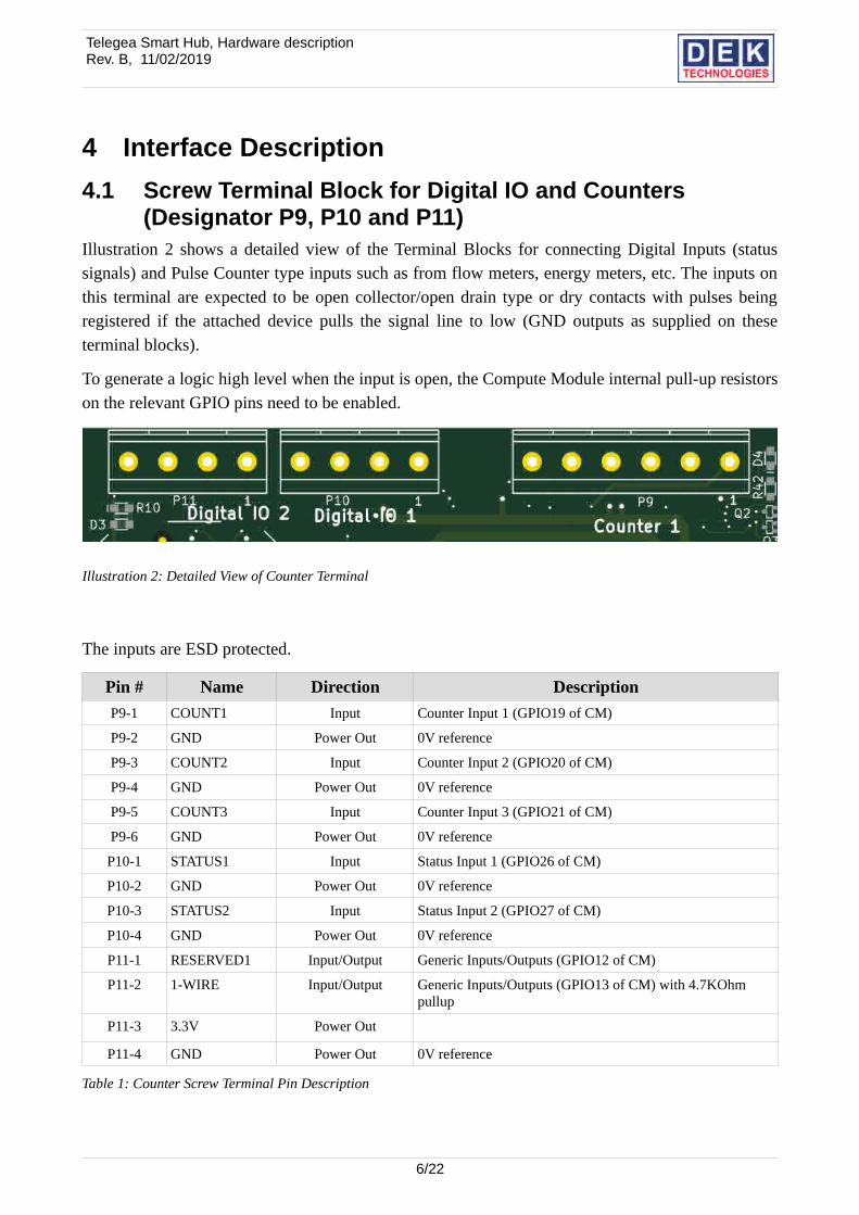
4.1 Screw Terminal Block for Digital IO and Counters (Designator P9, P10 and P11)
Illustration 2 shows a detailed view of the Terminal Blocks for connecting Digital Inputs (statussignals) and Pulse Counter type inputs such as from flow meters, energy meters, etc. The inputs onthis terminal are expected to be open collector/open drain type or dry contacts with pulses beingregistered if the attached device pulls the signal line to low (GND outputs as supplied on theseterminal blocks).
To generate a logic high level when the input is open, the Compute Module internal pull-up resistorson the relevant GPIO pins need to be enabled.
The inputs are ESD protected.
Pin # Name Direction Description
P9-1 COUNT1 Input Counter Input 1 (GPIO19 of CM)
P9-2 GND Power Out 0V reference
P9-3 COUNT2 Input Counter Input 2 (GPIO20 of CM)
P9-4 GND Power Out 0V reference
P9-5 COUNT3 Input Counter Input 3 (GPIO21 of CM)
P9-6 GND Power Out 0V reference
P10-1 STATUS1 Input Status Input 1 (GPIO26 of CM)
P10-2 GND Power Out 0V reference
P10-3 STATUS2 Input Status Input 2 (GPIO27 of CM)
P10-4 GND Power Out 0V reference
P11-1 RESERVED1 Input/Output Generic Inputs/Outputs (GPIO12 of CM)
P11-2 1-WIRE Input/Output Generic Inputs/Outputs (GPIO13 of CM) with 4.7KOhm pullup
P11-3 3.3V Power Out
P11-4 GND Power Out 0V reference
Table 1: Counter Screw Terminal Pin Description
6/22
Illustration 2: Detailed View of Counter Terminal
Telegea Smart Hub, Hardware descriptionRev. B, 11/02/2019
Symbol Parameter Conditions Min Typ Max Units
VinInput Signal Voltage
Typically these inputs should be left floating if not used or the signal is inactive.
0 -- 3.3 V
VESD
ESD Protection − Peak Discharge Voltage at any Input
8 -- -- kV
Table 2: Ratings for Digital IO and Counter Screw Terminals
4.2 Micro USB Socket (Designator J2)Note: This connector is not mounted on PCB revision R3C0.
This connector is a standard USB slave socket (Micro-B) and this interface conforms to the standard USB specifications [1] .
4.3 USB Socket (Host) (Designator J3)This connector is a standard 2 port USB host socket (Type-A) and this interface conforms to the standard USB specifications [1].
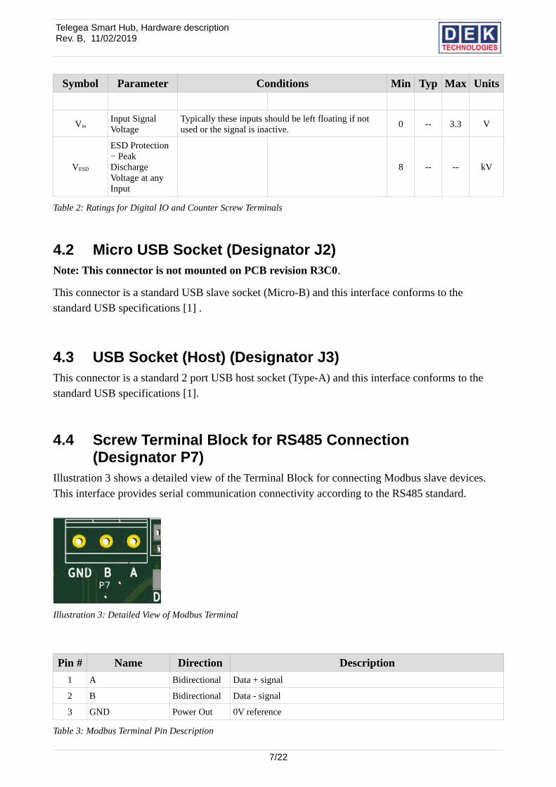
4.4 Screw Terminal Block for RS485 Connection (Designator P7)
Illustration 3 shows a detailed view of the Terminal Block for connecting Modbus slave devices. This interface provides serial communication connectivity according to the RS485 standard.
Pin # Name Direction Description
1 A Bidirectional Data + signal
2 B Bidirectional Data - signal
3 GND Power Out 0V reference
Table 3: Modbus Terminal Pin Description
7/22
Illustration 3: Detailed View of Modbus Terminal
Telegea Smart Hub, Hardware descriptionRev. B, 11/02/2019
Symbol Parameter Min Typ Max Units
VI Voltage range at A or B Inputs -13 16.5 V
VIH High-level input voltage (Driver, driver enable, and receiver enable inputs) 2 Vcc V
VIL Low-level input voltage (Driver, driver enable, and receiver enable inputs) 0 0.8 V
VID Differential input voltage -12 12 V
IO Output current, Driver -60 60 mA
IO Output current, Receiver -8 8 mA
Table 4: RS485 Terminal Ratings
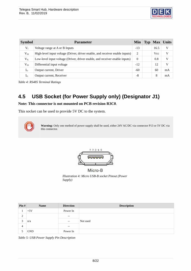
4.5 USB Socket (for Power Supply only) (Designator J1)Note: This connector is not mounted on PCB revision R3C0.
This socket can be used to provide 5V DC to the system.
Warning: Only one method of power supply shall be used, either 24V AC/DC via connector P13 or 5V DC via this connector.
Pin # Name Direction Description
1 +5V Power In
2
n/a
--
Not used3 --
4 --
5 GND Power In
Table 5: USB Power Supply Pin Description
8/22
Illustration 4: Micro USB-B socket Pinout (Power Supply)
Telegea Smart Hub, Hardware descriptionRev. B, 11/02/2019
Symbol Parameter Conditions Min Typ Max Units
Ipwr_DC Current Consumption ? 2000 mA
V
mA
Table 6: Ratings for USB Power Supply Connector
Warning: The actual current draw is somewhat dependant on extension modules that are being connected aswell as the programming of the Raspberry Compute Module. Care has to be taken that the overall currentconsumption does not exceed 2A.
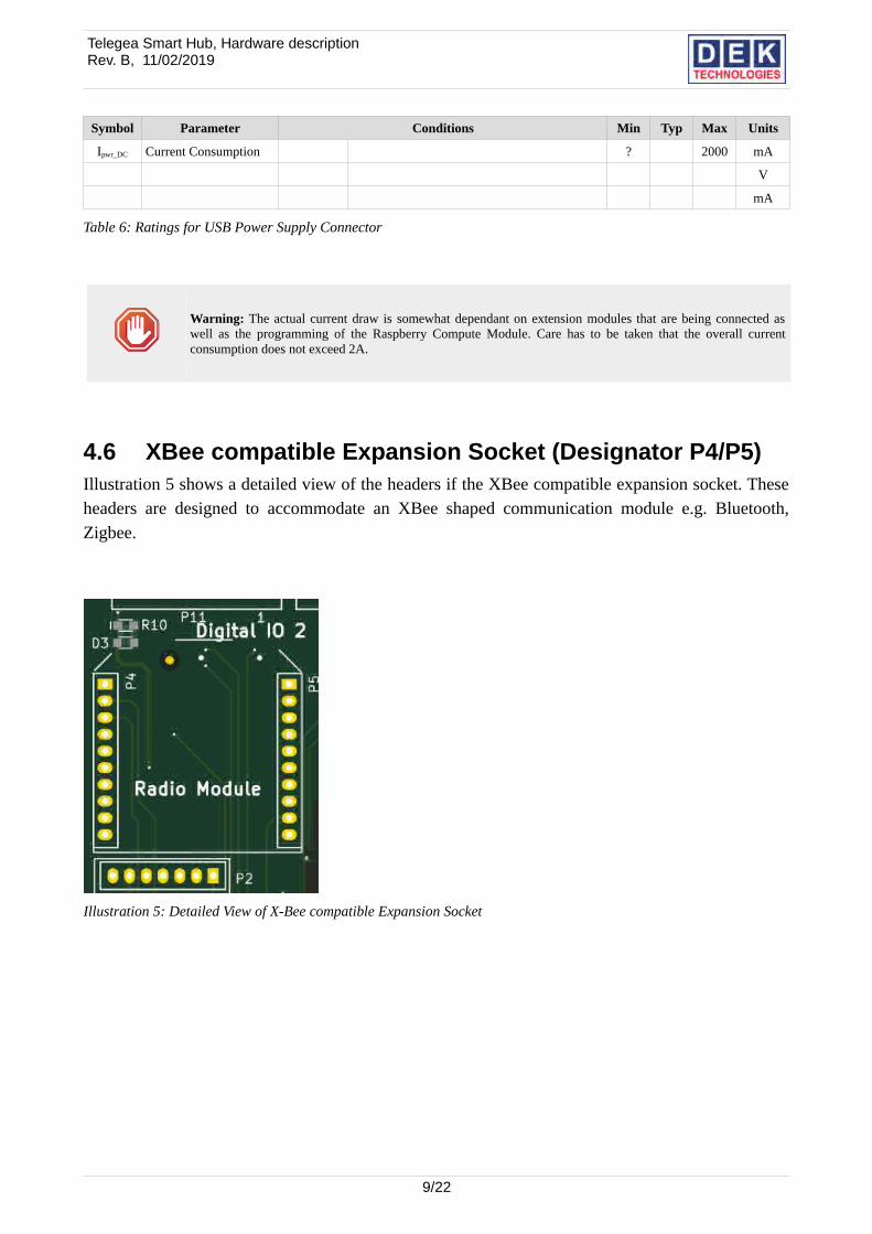
4.6 XBee compatible Expansion Socket (Designator P4/P5)Illustration 5 shows a detailed view of the headers if the XBee compatible expansion socket. Theseheaders are designed to accommodate an XBee shaped communication module e.g. Bluetooth,Zigbee.
9/22
Illustration 5: Detailed View of X-Bee compatible Expansion Socket
Telegea Smart Hub, Hardware descriptionRev. B, 11/02/2019
Pin # Name Direction Description
P4-1 3V3 Power out 3.3V Power supply for module
P4-2 TX Output RS232 transmit line (shared with debug port P1)
P4-3 RX Input RS232 receive line (shared with debug port P1)
P4-4 RTS Output RS232 RTS line
P4-5 N.C -- Not connected
P4-6 HBEAT Input Heartbeat signal from module connected to on-board led
P4-7 N.C -- Not connected
P4-8 N.C -- Not connected
P4-9 N.C -- Not connected
P4-10 GND Power Out 0V reference
P5-1 N.C -- Not connected
P5-2 N.C -- Not connected
P5-3 N.C -- Not connected
P5-4 N.C -- Not connected
P5-5 N.C -- Not connected
P5-6 N.C -- Not connected
P5-7 N.C -- Not connected
P5-8 N.C -- Not connected
P5-9 CTS Output RS232 CTS line
P5-10 N.C -- Not connected
Table 7: XBee compatible expansion headers Pin Description
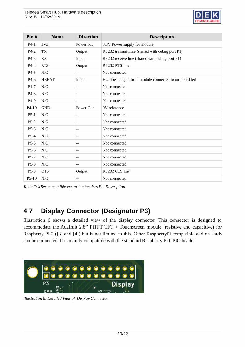
4.7 Display Connector (Designator P3)Illustration 6 shows a detailed view of the display connector. This connector is designed toaccommodate the Adafruit 2.8’’ PiTFT TFT + Touchscreen module (resistive and capacitive) forRaspberry Pi 2 ([3] and [4]) but is not limited to this. Other RaspberryPi compatible add-on cardscan be connected. It is mainly compatible with the standard Raspberry Pi GPIO header.
10/22
Illustration 6: Detailed View of Display Connector
Telegea Smart Hub, Hardware descriptionRev. B, 11/02/2019
Pin # Name Direction Description
1 +3V3 Power Output 3.3V supply voltage for use by Display
2 +5V Power Output 5V supply voltage for use by Display
3 LCD_TP_SDA1 Bidirectional GPIO2 of CM
4 +5V Power Output 5V supply voltage for use by Display
5 LCD_TP_SCL1 Output GPIO3 of CM
6 GND Power Output 0V Reference
7 N.C -- Not connected
8 RS232_TXD1 Output RS232 transmit line (shared with debug port P1 and P4)
9 GND Power Output 0V Reference
10 RS232_RXD1 Intput RS232 receive line (shared with debug port P1 and P4)
11 N.C -- Not connected
12 LCD_LITE Output GPIO18 of CM
13 N.C -- Not connected
14 GND Power Output 0V Reference
15 N.C -- Not connected
16 N.C -- Not connected
17 +3V3 Power Output 3.3V supply voltage for use by Display
18 LCD_TP_IRQ Input GPIO24 of CM
19 LCD_SPI0_MOSI Output GPIO10 of CM
20 GND Power Output 0V Reference
21 LCD_SPI0_MISO Input GPIO9 of CM
22 LCD_DC GPIO25 of CM
23 LCD_SPI0_SCLK Output GPIO11 of CM
24 LCD_SPI0_CE0N Output GPIO8 of CM
25 GND Power Output 0V Reference
26 LCD_SPI0_CE1N Output GPIO7 of CM
Table 8: Display Connector Pin Description
11/22
Telegea Smart Hub, Hardware descriptionRev. B, 11/02/2019
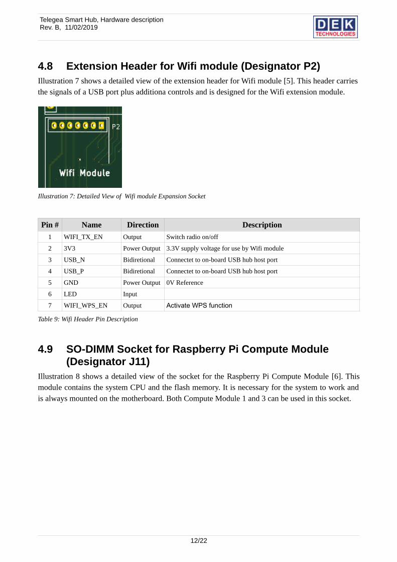
4.8 Extension Header for Wifi module (Designator P2)Illustration 7 shows a detailed view of the extension header for Wifi module [5]. This header carriesthe signals of a USB port plus additiona controls and is designed for the Wifi extension module.
Pin # Name Direction Description
1 WIFI_TX_EN Output Switch radio on/off
2 3V3 Power Output 3.3V supply voltage for use by Wifi module
3 USB_N Bidiretional Connectet to on-board USB hub host port
4 USB_P Bidiretional Connectet to on-board USB hub host port
5 GND Power Output 0V Reference
6 LED Input
7 WIFI_WPS_EN Output Activate WPS function
Table 9: Wifi Header Pin Description
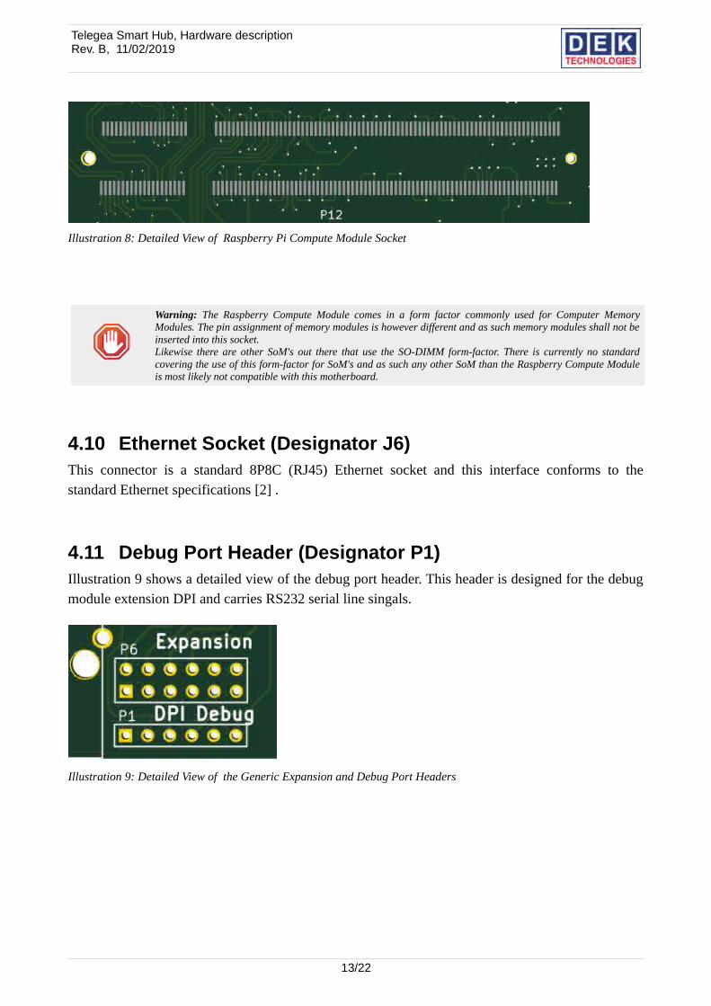
4.9 SO-DIMM Socket for Raspberry Pi Compute Module (Designator J11)
Illustration 8 shows a detailed view of the socket for the Raspberry Pi Compute Module [6]. Thismodule contains the system CPU and the flash memory. It is necessary for the system to work andis always mounted on the motherboard. Both Compute Module 1 and 3 can be used in this socket.
12/22
Illustration 7: Detailed View of Wifi module Expansion Socket
Telegea Smart Hub, Hardware descriptionRev. B, 11/02/2019
Warning: The Raspberry Compute Module comes in a form factor commonly used for Computer MemoryModules. The pin assignment of memory modules is however different and as such memory modules shall not beinserted into this socket. Likewise there are other SoM's out there that use the SO-DIMM form-factor. There is currently no standardcovering the use of this form-factor for SoM's and as such any other SoM than the Raspberry Compute Moduleis most likely not compatible with this motherboard.
4.10 Ethernet Socket (Designator J6)This connector is a standard 8P8C (RJ45) Ethernet socket and this interface conforms to thestandard Ethernet specifications [2] .
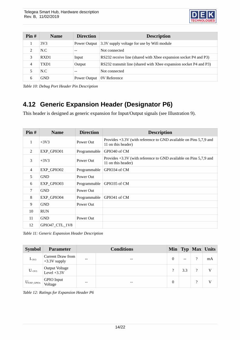
4.11 Debug Port Header (Designator P1)Illustration 9 shows a detailed view of the debug port header. This header is designed for the debugmodule extension DPI and carries RS232 serial line singals.
13/22
Illustration 9: Detailed View of the Generic Expansion and Debug Port Headers
Illustration 8: Detailed View of Raspberry Pi Compute Module Socket
Telegea Smart Hub, Hardware descriptionRev. B, 11/02/2019
Pin # Name Direction Description
1 3V3 Power Output 3.3V supply voltage for use by Wifi module
2 N.C -- Not connected
3 RXD1 Input RS232 receive line (shared with Xbee expansion socket P4 and P3)
4 TXD1 Output RS232 transmit line (shared with Xbee expansion socket P4 and P3)
5 N.C -- Not connected
6 GND Power Output 0V Reference
Table 10: Debug Port Header Pin Description
4.12 Generic Expansion Header (Designator P6)This header is designed as generic expansion for Input/Output signals (see Illustration 9).
Pin # Name Direction Description
1 +3V3 Power OutProvides +3.3V (with reference to GND available on Pins 5,7,9 and 11 on this header)
2 EXP_GPIO01 Programmable GPIO40 of CM
3 +3V3 Power OutProvides +3.3V (with reference to GND available on Pins 5,7,9 and 11 on this header)
4 EXP_GPIO02 Programmable GPIO34 of CM
5 GND Power Out
6 EXP_GPIO03 Programmable GPIO35 of CM
7 GND Power Out
8 EXP_GPIO04 Programmable GPIO41 of CM
9 GND Power Out
10 RUN
11 GND Power Out
12 GPIO47_CTL_1V8
Table 11: Generic Expansion Header Description
Symbol Parameter Conditions Min Typ Max Units
I+3V3Current Draw from+3.3V supply
-- -- 0 -- ? mA
U+3V3Output Voltage Level +3.3V
? 3.3 ? V
UEXP_GPIOxGPIO Input Voltage
-- -- 0 ? V
Table 12: Ratings for Expansion Header P6
14/22
Telegea Smart Hub, Hardware descriptionRev. B, 11/02/2019
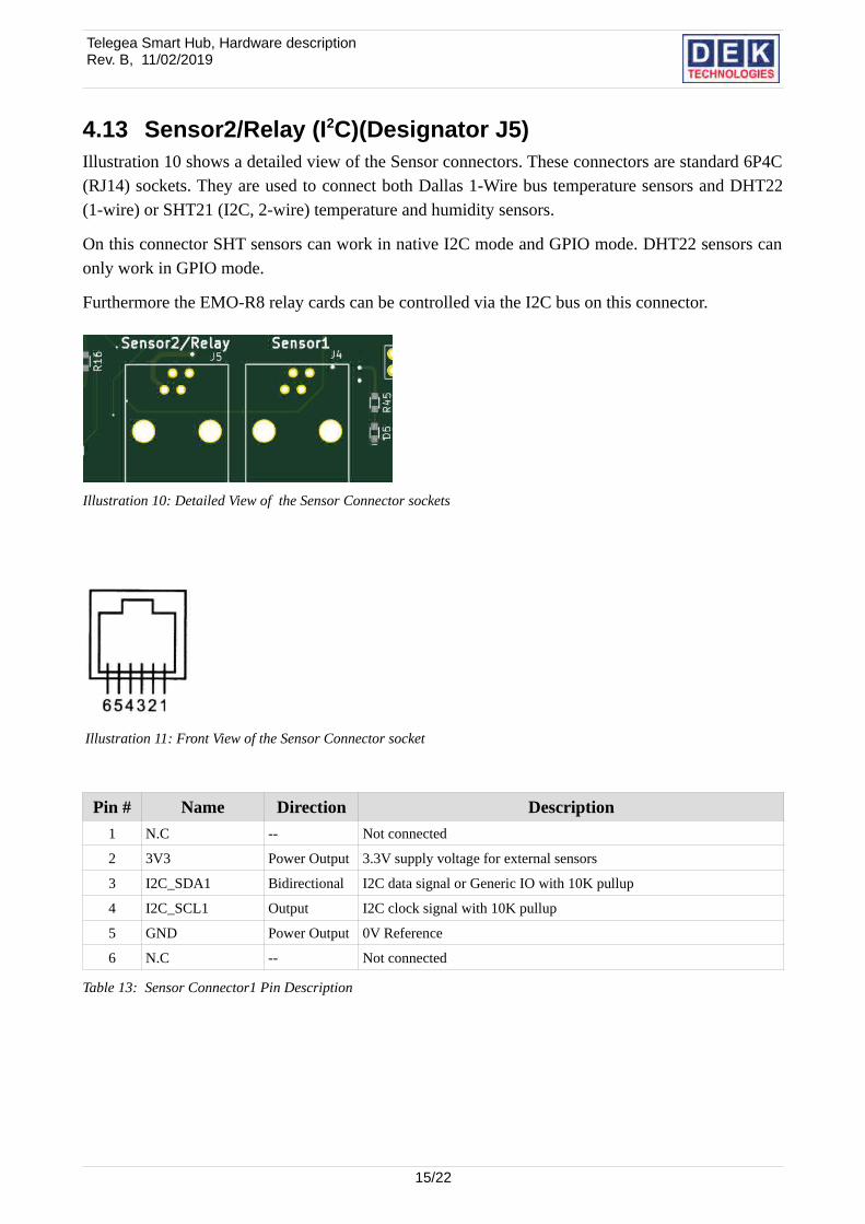
4.13 Sensor2/Relay (I2C)(Designator J5)Illustration 10 shows a detailed view of the Sensor connectors. These connectors are standard 6P4C(RJ14) sockets. They are used to connect both Dallas 1-Wire bus temperature sensors and DHT22(1-wire) or SHT21 (I2C, 2-wire) temperature and humidity sensors.
On this connector SHT sensors can work in native I2C mode and GPIO mode. DHT22 sensors canonly work in GPIO mode.
Furthermore the EMO-R8 relay cards can be controlled via the I2C bus on this connector.
Pin # Name Direction Description
1 N.C -- Not connected
2 3V3 Power Output 3.3V supply voltage for external sensors
3 I2C_SDA1 Bidirectional I2C data signal or Generic IO with 10K pullup
4 I2C_SCL1 Output I2C clock signal with 10K pullup
5 GND Power Output 0V Reference
6 N.C -- Not connected
Table 13: Sensor Connector1 Pin Description
15/22
Illustration 10: Detailed View of the Sensor Connector sockets
Illustration 11: Front View of the Sensor Connector socket
Telegea Smart Hub, Hardware descriptionRev. B, 11/02/2019
4.14 Sensor Connector 1 (SPI) (Designator J4) Note: This connector is not mounted on PCB revision R3C0.
Same as chapter 4.13
On this connector SHT sensors can work only in GPIO mode. DHT22 sensors can work in SPImode and GPIO mode.
Pin # Name Direction Description
1 N.C -- Not connected
2 3V3 Power Output 3.3V supply voltage for external sensors
3 SPI0_MOSI Output SPI Master Out Slave In signal with 10K pullup
4 SPI0_MISO Input SPI Master In Slave Out signal or Generic IO with 10K pullup
5 GND Power Output 0V Reference
6 N.C -- Not connected
Table 14: Sensor Connector1 Pin Description
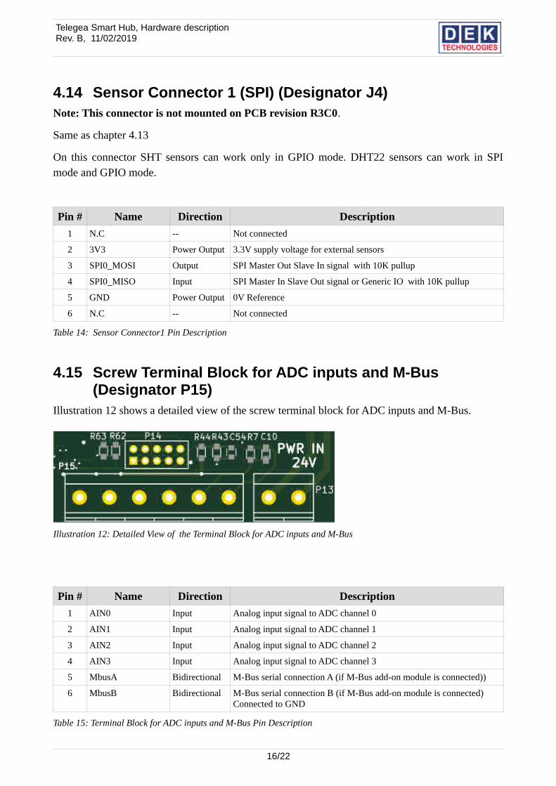
4.15 Screw Terminal Block for ADC inputs and M-Bus (Designator P15)
Illustration 12 shows a detailed view of the screw terminal block for ADC inputs and M-Bus.
Pin # Name Direction Description
1 AIN0 Input Analog input signal to ADC channel 0
2 AIN1 Input Analog input signal to ADC channel 1
3 AIN2 Input Analog input signal to ADC channel 2
4 AIN3 Input Analog input signal to ADC channel 3
5 MbusA Bidirectional M-Bus serial connection A (if M-Bus add-on module is connected))
6 MbusB Bidirectional M-Bus serial connection B (if M-Bus add-on module is connected)Connected to GND
Table 15: Terminal Block for ADC inputs and M-Bus Pin Description
16/22
Illustration 12: Detailed View of the Terminal Block for ADC inputs and M-Bus
Telegea Smart Hub, Hardware descriptionRev. B, 11/02/2019
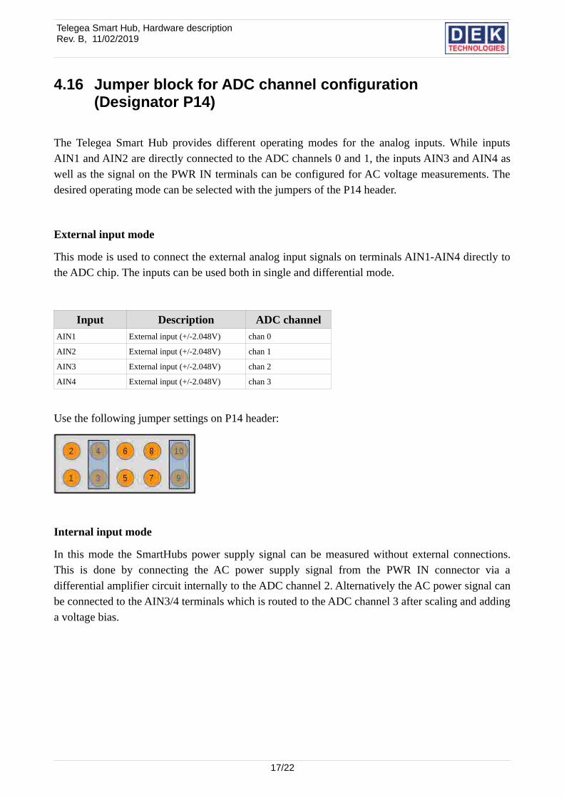
4.16 Jumper block for ADC channel configuration (Designator P14)
The Telegea Smart Hub provides different operating modes for the analog inputs. While inputsAIN1 and AIN2 are directly connected to the ADC channels 0 and 1, the inputs AIN3 and AIN4 aswell as the signal on the PWR IN terminals can be configured for AC voltage measurements. Thedesired operating mode can be selected with the jumpers of the P14 header.
External input mode
This mode is used to connect the external analog input signals on terminals AIN1-AIN4 directly tothe ADC chip. The inputs can be used both in single and differential mode.
Input Description ADC channelAIN1 External input (+/-2.048V) chan 0
AIN2 External input (+/-2.048V) chan 1
AIN3 External input (+/-2.048V) chan 2
AIN4 External input (+/-2.048V) chan 3
Use the following jumper settings on P14 header:
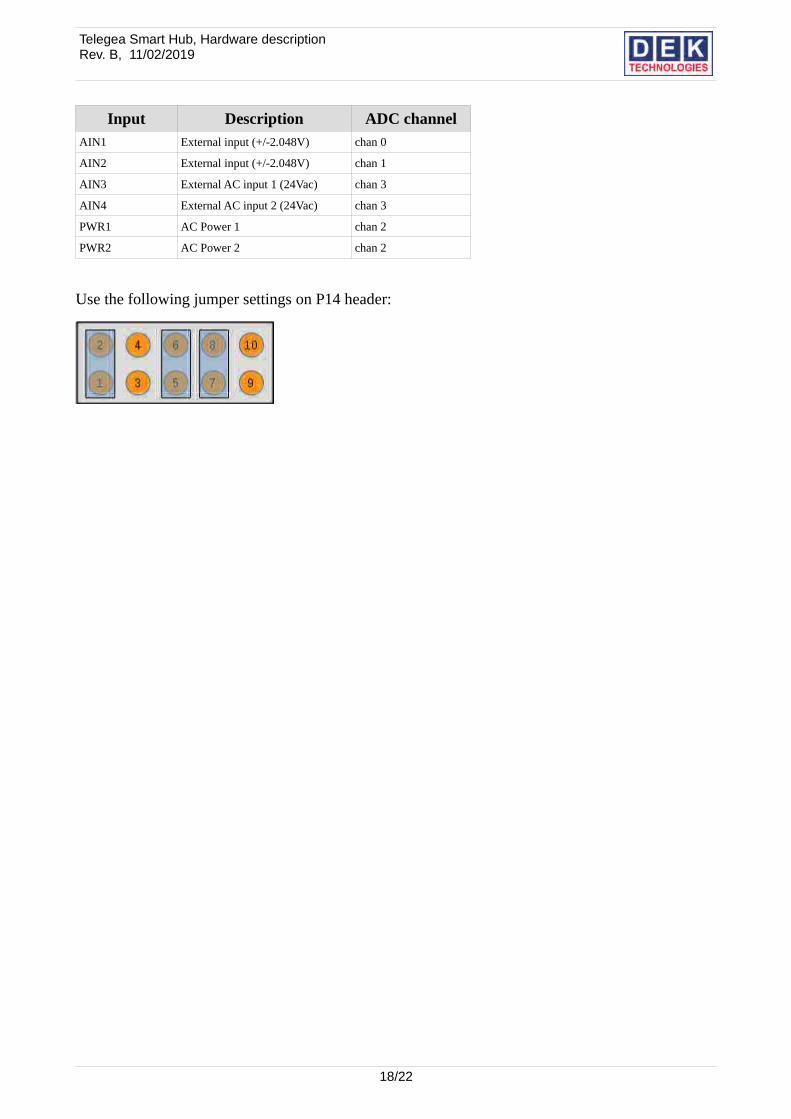
Internal input mode
In this mode the SmartHubs power supply signal can be measured without external connections.This is done by connecting the AC power supply signal from the PWR IN connector via adifferential amplifier circuit internally to the ADC channel 2. Alternatively the AC power signal canbe connected to the AIN3/4 terminals which is routed to the ADC channel 3 after scaling and addinga voltage bias.
17/22
Telegea Smart Hub, Hardware descriptionRev. B, 11/02/2019
Input Description ADC channelAIN1 External input (+/-2.048V) chan 0
AIN2 External input (+/-2.048V) chan 1
AIN3 External AC input 1 (24Vac) chan 3
AIN4 External AC input 2 (24Vac) chan 3
PWR1 AC Power 1 chan 2
PWR2 AC Power 2 chan 2
Use the following jumper settings on P14 header:
18/22
Telegea Smart Hub, Hardware descriptionRev. B, 11/02/2019
4.17 Screw Terminal Block for DC Power (Designator P13)
Pin # Name Direction Description1 24V Input AC power inputs
2 24V Input
Table 16: AC Power Connector Description
Symbol Parameter Conditions Min Typ Max UnitsVIN Supply Voltage (AC) -- -- 9 24 30 V (AC)
Table 17: AC Power Ratings
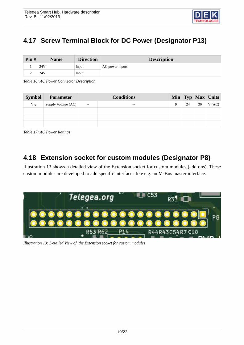
4.18 Extension socket for custom modules (Designator P8)Illustration 13 shows a detailed view of the Extension socket for custom modules (add ons). Thesecustom modules are developed to add specific interfaces like e.g. an M-Bus master interface.
19/22
Illustration 13: Detailed View of the Extension socket for custom modules
Telegea Smart Hub, Hardware descriptionRev. B, 11/02/2019
Pin # Name Direction Description1 N.C. -- Not connected
2 VCC5 Power Output 5V supply voltage for add-on module
3 I2C_SDA Bidirectional I2C data
4 VCC5 Power Output 5V supply voltage for add-on module
5 I2C_SCL Output I2C clock
6 GND Power Output 0V Reference
7 N.C. -- Not connected
8 USB_N Bidirectional USB data line for add-on module
9 GND Power Output 0V Reference
10 USB_P Bidirectional USB data line for add-on module
11 N.C. -- Not connected
12 N.C. -- Not connected
13 MBUS_A Bidirectional M-Bus data line from M-Bus add-on module
14 GND Power Output 0V Reference
15 N.C. -- Not connected
16 N.C. -- Not connected
17 N.C. -- Not connected
18 N.C. -- Not connected
19 SPI_MOSI -- SPI MOSI data
20 GND Power Output 0V Reference
21 SPI_MISO. -- SPI MISO data
22 N.C. -- Not connected
23 SPI_CLK -- SPI clock
24 SPI_CE0 -- SPI chip enable 0
25 GND Power Output 0V Reference
26 SPI_CE1 -- SPI chip enable 1
27 N.C. -- Not connected
28 N.C. -- Not connected
29 MBUS_STS Input M-Bus status signal from M-Bus add-on module
30 GND Power Output 0V Reference
31 N.C. -- Not connected
32 N.C. -- Not connected
33 N.C. -- Not connected
34 GND Power Output 0V Reference
35 GPIO39 -- GPIO39 of CM
36 MBUS_PWREN Output M-Bus power enable signal to M-Bus add-on module
37 GPIO43 -- GPIO43 of CM
38 GPIO34 -- GPIO34 of CM
39 GND Power Output 0V Reference
40 GPIO40 -- GPIO40 of CM
Table 18: Extension socket for custom modules Pin Description
20/22
Telegea Smart Hub, Hardware descriptionRev. B, 11/02/2019
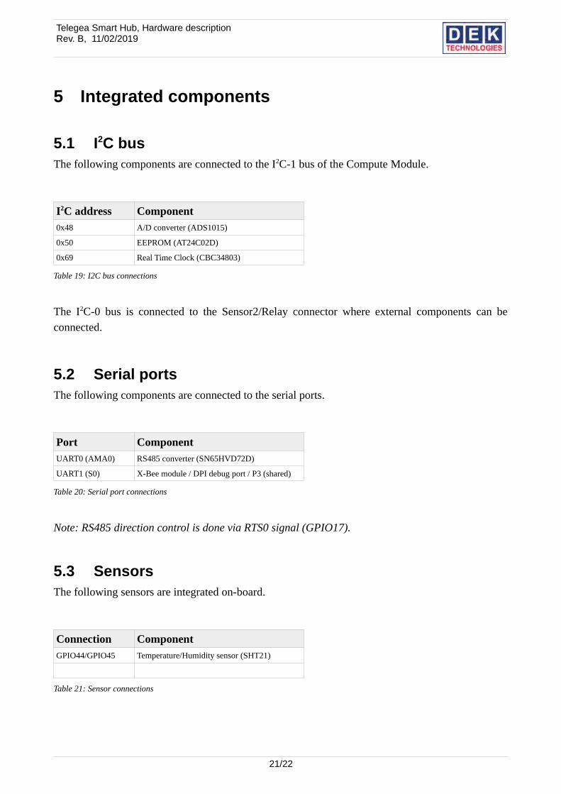
5 Integrated components
5.1 I2C busThe following components are connected to the I2C-1 bus of the Compute Module.
I2C address Component0x48 A/D converter (ADS1015)
0x50 EEPROM (AT24C02D)
0x69 Real Time Clock (CBC34803)
Table 19: I2C bus connections
The I2C-0 bus is connected to the Sensor2/Relay connector where external components can beconnected.
5.2 Serial portsThe following components are connected to the serial ports.
Port ComponentUART0 (AMA0) RS485 converter (SN65HVD72D)
UART1 (S0) X-Bee module / DPI debug port / P3 (shared)
Table 20: Serial port connections
Note: RS485 direction control is done via RTS0 signal (GPIO17).
5.3 SensorsThe following sensors are integrated on-board.
Connection ComponentGPIO44/GPIO45 Temperature/Humidity sensor (SHT21)
Table 21: Sensor connections
21/22
Telegea Smart Hub, Hardware descriptionRev. B, 11/02/2019
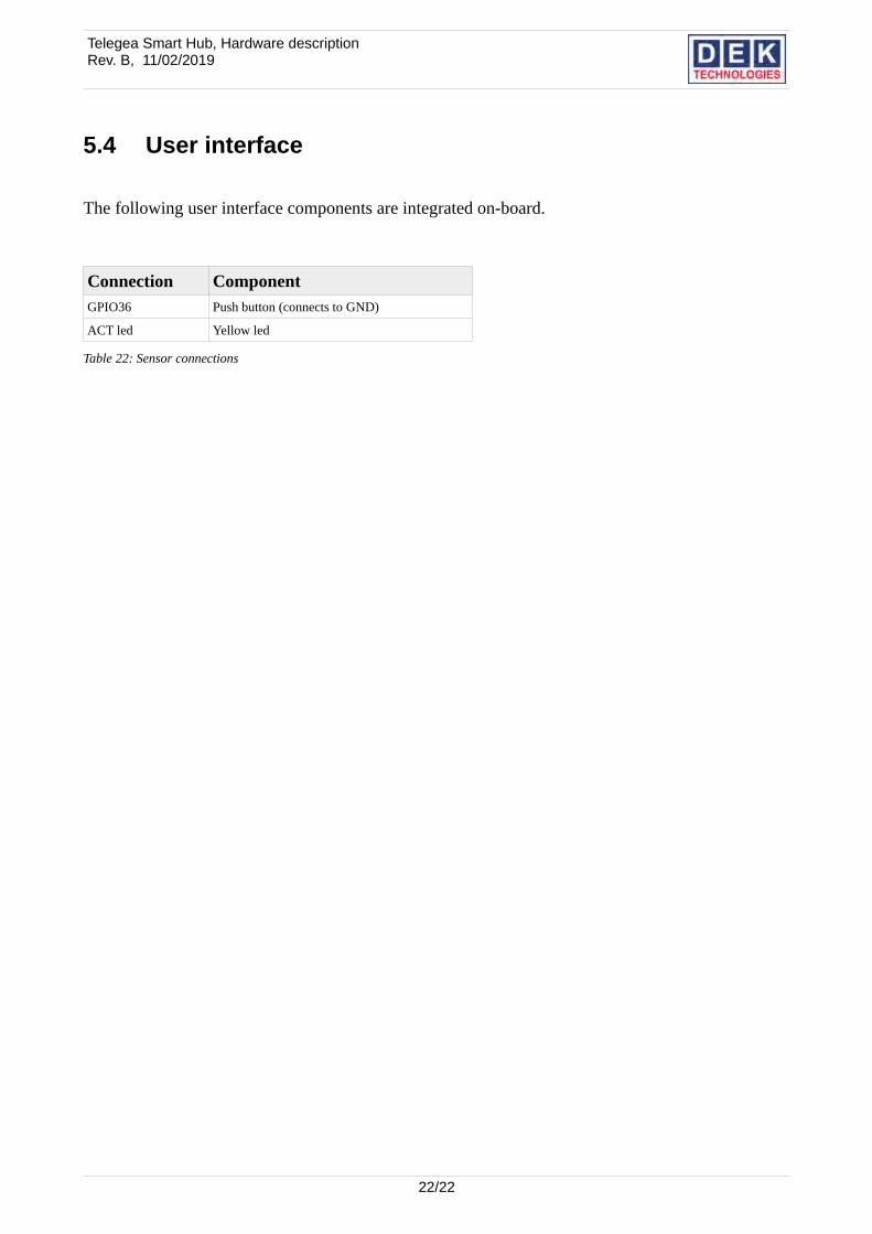
5.4 User interface
The following user interface components are integrated on-board.
Connection ComponentGPIO36 Push button (connects to GND)
ACT led Yellow led
Table 22: Sensor connections
22/22