Embed Size (px)
Citation preview
RU3832&RU3632
Hardware Description
Issue 03
Date 2014-01-20
HUAWEI TECHNOLOGIES CO., LTD.
Issue 03 (2014-01-20) Huawei Proprietary and Confidential
Copyright © Huawei Technologies Co., Ltd. i
Copyright © Huawei Technologies Co., Ltd. 2014. All rights reserved.
No part of this document may be reproduced or transmitted in any form or by any means without prior
written consent of Huawei Technologies Co., Ltd.
Trademarks and Permissions
and other Huawei trademarks are trademarks of Huawei Technologies Co., Ltd.
All other trademarks and trade names mentioned in this document are the property of their respective
holders.
Notice
The purchased products, services and features are stipulated by the contract made between Huawei and
the customer. All or part of the products, services and features described in this document may not be
within the purchase scope or the usage scope. Unless otherwise specified in the contract, all statements,
information, and recommendations in this document are provided "AS IS" without warranties, guarantees or
representations of any kind, either express or implied.
The information in this document is subject to change without notice. Every effort has been made in the
preparation of this document to ensure accuracy of the contents, but all statements, information, and
recommendations in this document do not constitute a warranty of any kind, express or implied.
Huawei Technologies Co., Ltd.
Address: Huawei Industrial Base
Bantian, Longgang
Shenzhen 518129
People's Republic of China
Website: http://www.huawei.com
Email: [email protected]
RRU3832&RRU3632
Hardware Description About This Document
Issue 03 (2014-01-20) Huawei Proprietary and Confidential
Copyright © Huawei Technologies Co., Ltd.
ii
About This Document
Purpose
This document provides reference for planning and deploying DC blade RU3832 and RU3632
(referred to as RU in this document). It presents the exterior and describes the ports, functions,
cable types, connector specifications, and cable connections of the RU.
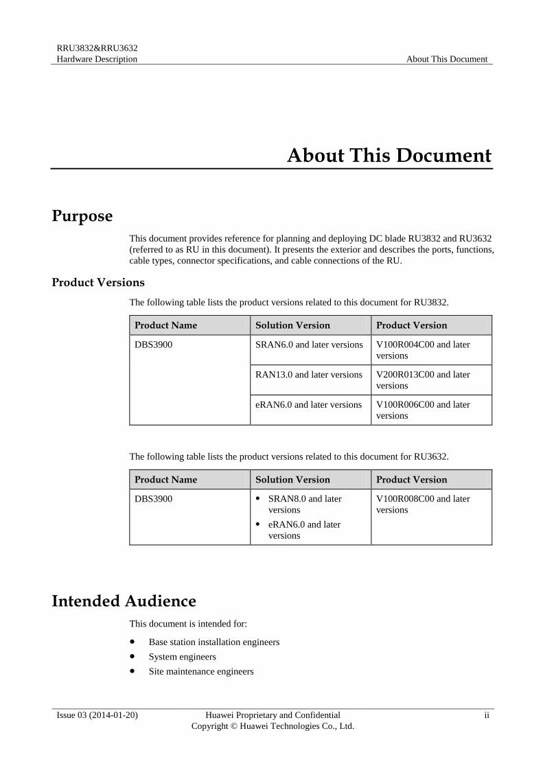
Product Versions
The following table lists the product versions related to this document for RU3832.
Product Name Solution Version Product Version
DBS3900 SRAN6.0 and later versions V100R004C00 and later
versions
RAN13.0 and later versions V200R013C00 and later
versions
eRAN6.0 and later versions V100R006C00 and later
versions
The following table lists the product versions related to this document for RU3632.
Product Name Solution Version Product Version
DBS3900 SRAN8.0 and later
versions
eRAN6.0 and later
versions
V100R008C00 and later
versions
Intended Audience
This document is intended for:
Base station installation engineers
System engineers
Site maintenance engineers
RRU3832&RRU3632
Hardware Description About This Document
Issue 03 (2014-01-20) Huawei Proprietary and Confidential
Copyright © Huawei Technologies Co., Ltd.
iii
Organization
1 Changes in RU3832&RU3632 Hardware Description
This chapter describes the changes in RU3832&RU3632 Hardware Description.
2 RU Introduction
This chapter describes the exterior and function of the RU as well as the ports and indicators
on the RU.
3 RU Cables
This chapter describes RU cables.
4 RF Cable Connections for the RU3832&RU3632
RF cable connections for the RU vary depending on the configurations of the RU and
antenna.
5 RU Auxiliary Devices
This chapter describes RU auxiliary devices.
Conventions
Symbol Conventions
The symbols that may be found in this document are defined as follows.
Symbol Description
Indicates an imminently hazardous situation which, if not
avoided, will result in death or serious injury.
Indicates a potentially hazardous situation which, if not
avoided, could result in death or serious injury.
Indicates a potentially hazardous situation which, if not
avoided, may result in minor or moderate injury.
Indicates a potentially hazardous situation which, if not
avoided, could result in equipment damage, data loss,
performance deterioration, or unanticipated results.
NOTICE is used to address practices not related to personal
injury.
Calls attention to important information, best practices and
tips.
NOTE is used to address information not related to personal
injury, equipment damage, and environment deterioration.
RRU3832&RRU3632
Hardware Description About This Document
Issue 03 (2014-01-20) Huawei Proprietary and Confidential
Copyright © Huawei Technologies Co., Ltd.
iv
General Conventions
Convention Description
Times New Roman Normal paragraphs are in Times New Roman.
Boldface Names of files, directories, folders, and users are in
boldface. For example, log in as user root.
Italic Book titles are in italics.
Courier New Terminal display is in Courier New.
Command Conventions
Convention Description
Boldface The keywords of a command line are in boldface.
Italic Command arguments are in italics.
[ ] Items (keywords or arguments) in square brackets [ ] are
optional.
{ x | y | ... } Alternative items are grouped in braces and separated by
vertical bars. One is selected.
[ x | y | ... ] Optional alternative items are grouped in square brackets
and separated by vertical bars. One or none is selected.
{ x | y | ... } * Alternative items are grouped in braces and separated by
vertical bars. A minimum of one or a maximum of all can
be selected.
GUI Conventions
Convention Description
Boldface Buttons, menus, parameters, tabs, windows, and dialog titles
are in boldface. For example, click OK.
> Multi-level menus are in boldface and separated by the ">"
signs. For example, choose File > Create > Folder.
Keyboard Operation
Format Description
Key Press the key. For example, press Enter and press Tab.
RRU3832&RRU3632
Hardware Description About This Document
Issue 03 (2014-01-20) Huawei Proprietary and Confidential
Copyright © Huawei Technologies Co., Ltd.
v
Format Description
Key 1+Key 2 Press the keys concurrently. For example, pressing
Ctrl+Alt+A means the three keys should be pressed
concurrently.
Key 1, Key 2 Press the keys in turn. For example, pressing Alt, A means
the two keys should be pressed in turn.
Mouse Operation
Action Description
Click Select and release the primary mouse button without
moving the pointer.
Double-click Press the primary mouse button twice continuously and
quickly without moving the pointer.
Drag Press and hold the primary mouse button and move the
pointer to a certain position.
RRU3832&RRU3632
Hardware Description Contents
Issue 03 (2014-01-20) Huawei Proprietary and Confidential
Copyright © Huawei Technologies Co., Ltd.
vi
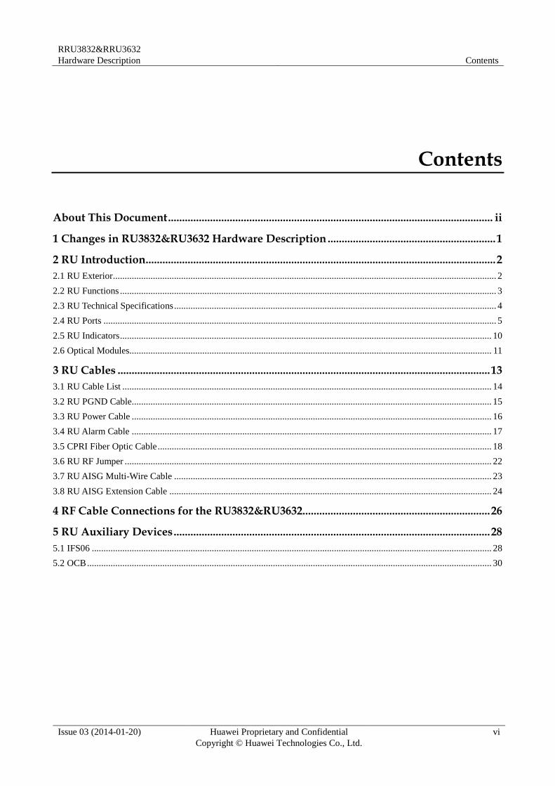
Contents
About This Document .................................................................................................................... ii
1 Changes in RU3832&RU3632 Hardware Description ............................................................ 1
2 RU Introduction............................................................................................................................. 2
2.1 RU Exterior ................................................................................................................................................................... 2
2.2 RU Functions ................................................................................................................................................................ 3
2.3 RU Technical Specifications ......................................................................................................................................... 4
2.4 RU Ports ....................................................................................................................................................................... 5
2.5 RU Indicators .............................................................................................................................................................. 10
2.6 Optical Modules.......................................................................................................................................................... 11
3 RU Cables ..................................................................................................................................... 13
3.1 RU Cable List ............................................................................................................................................................. 14
3.2 RU PGND Cable......................................................................................................................................................... 15
3.3 RU Power Cable ......................................................................................................................................................... 16
3.4 RU Alarm Cable ......................................................................................................................................................... 17
3.5 CPRI Fiber Optic Cable .............................................................................................................................................. 18
3.6 RU RF Jumper ............................................................................................................................................................ 22
3.7 RU AISG Multi-Wire Cable ....................................................................................................................................... 23
3.8 RU AISG Extension Cable ......................................................................................................................................... 24
4 RF Cable Connections for the RU3832&RU3632................................................................... 26
5 RU Auxiliary Devices ................................................................................................................. 28
5.1 IFS06 .......................................................................................................................................................................... 28
5.2 OCB ............................................................................................................................................................................ 30
RRU3832&RRU3632
Hardware Description 1 Changes in RU3832&RU3632 Hardware Description
Issue 03 (2014-01-20) Huawei Proprietary and Confidential
Copyright © Huawei Technologies Co., Ltd.
1
1 Changes in RU3832&RU3632 Hardware Description
This chapter describes the changes in RU3832&RU3632 Hardware Description.
03 (2014-01-20)
This is the third official release.
Compared with issue 02 (2013-07-30), this issue includes the following new information:
4 RF Cable Connections for the RU3832&RU3632.
Compared with issue 02 (2013-07-30), this issue does not include any changes.
Compared with issue 02 (2013-07-30), no information is deleted from this issue.
02 (2013-07-30)
This is the second official release.
Compared with issue 01 (2013-04-28), this issue does not include any new information.
Compared with issue 01 (2013-04-28), this issue includes the following changes:
Topic Change Description
2.4 RU Ports Added a detailed description of the alarm
port.
Compared with issue 01 (2013-04-28), no information is deleted from this issue.
01 (2013-04-28)
This is the first official release.
RRU3832&RRU3632
Hardware Description 2 RU Introduction
Issue 03 (2014-01-20) Huawei Proprietary and Confidential
Copyright © Huawei Technologies Co., Ltd.
2
2 RU Introduction
About This Chapter
This chapter describes the exterior and function of the RU as well as the ports and indicators
on the RU.
2.1 RU Exterior
This section describes the exterior and dimensions of an RU.
2.2 RU Functions
This section describes the main functions of the RU.
2.3 RU Technical Specifications
This section describes technical specifications of an RU, including supported modes,
frequency bands, RF specifications, engineering specifications, and antenna capabilities.
2.4 RU Ports
This section describes ports on the RU panels. An RU has a bottom panel, cabling cavity
panel, and indicator panel.
2.5 RU Indicators
This section describes six indicators on an RU. They indicate the running status.
2.6 Optical Modules
An optical module transmits optical signals between an optical port and a fiber optic cable.
2.1 RU Exterior
This section describes the exterior and dimensions of an RU.
Figure 2-1 shows an RU.
RRU3832&RRU3632
Hardware Description 2 RU Introduction
Issue 03 (2014-01-20) Huawei Proprietary and Confidential
Copyright © Huawei Technologies Co., Ltd.
3
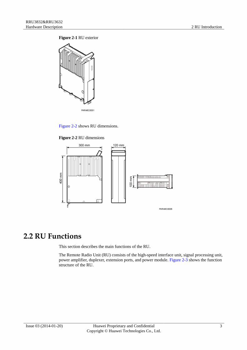
Figure 2-1 RU exterior
Figure 2-2 shows RU dimensions.
Figure 2-2 RU dimensions
2.2 RU Functions
This section describes the main functions of the RU.
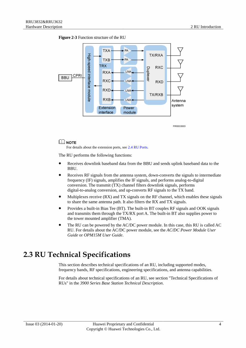
The Remote Radio Unit (RU) consists of the high-speed interface unit, signal processing unit,
power amplifier, duplexer, extension ports, and power module. Figure 2-3 shows the function
structure of the RU.
RRU3832&RRU3632
Hardware Description 2 RU Introduction
Issue 03 (2014-01-20) Huawei Proprietary and Confidential
Copyright © Huawei Technologies Co., Ltd.
4
Figure 2-3 Function structure of the RU
For details about the extension ports, see 2.4 RU Ports.
The RU performs the following functions:
Receives downlink baseband data from the BBU and sends uplink baseband data to the
BBU.
Receives RF signals from the antenna system, down-converts the signals to intermediate
frequency (IF) signals, amplifies the IF signals, and performs analog-to-digital
conversion. The transmit (TX) channel filters downlink signals, performs
digital-to-analog conversion, and up-converts RF signals to the TX band.
Multiplexes receive (RX) and TX signals on the RF channel, which enables these signals
to share the same antenna path. It also filters the RX and TX signals.
Provides a built-in Bias Tee (BT). The built-in BT couples RF signals and OOK signals
and transmits them through the TX/RX port A. The built-in BT also supplies power to
the tower mounted amplifier (TMA).
The RU can be powered by the AC/DC power module. In this case, this RU is called AC
RU. For details about the AC/DC power module, see the AC/DC Power Module User
Guide or OPM15M User Guide.
2.3 RU Technical Specifications
This section describes technical specifications of an RU, including supported modes,
frequency bands, RF specifications, engineering specifications, and antenna capabilities.
For details about technical specifications of an RU, see section "Technical Specifications of
RUs" in the 3900 Series Base Station Technical Description.
RRU3832&RRU3632
Hardware Description 2 RU Introduction
Issue 03 (2014-01-20) Huawei Proprietary and Confidential
Copyright © Huawei Technologies Co., Ltd.
5
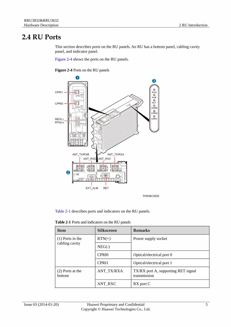
2.4 RU Ports
This section describes ports on the RU panels. An RU has a bottom panel, cabling cavity
panel, and indicator panel.
Figure 2-4 shows the ports on the RU panels.
Figure 2-4 Ports on the RU panels
Table 2-1 describes ports and indicators on the RU panels.
Table 2-1 Ports and indicators on the RU panels
Item Silkscreen Remarks
(1) Ports in the
cabling cavity
RTN(+) Power supply socket
NEG(-)
CPRI0 Optical/electrical port 0
CPRI1 Optical/electrical port 1
(2) Ports at the
bottom
ANT_TX/RXA TX/RX port A, supporting RET signal
transmission
ANT_RXC RX port C
RRU3832&RRU3632
Hardware Description 2 RU Introduction
Issue 03 (2014-01-20) Huawei Proprietary and Confidential
Copyright © Huawei Technologies Co., Ltd.
6
Item Silkscreen Remarks
ANT_RXD Port RX port D
ANT_TX/RXB TX/RX port B
EXT_ALM Alarm monitoring port used for monitoring
one RS485 signal and two dry contact
signals
RET Communication port for the RET antenna,
supporting RET signal transmission
(3) Indicators RUN See 2.5 RU Indicators.
ALM
ACT
VSWR
CPRI0
CPRI1
The port for transmitting RET signals is determined by the software.
For the RU3832, CPRI0 is connected to the BBU or an upper-level RU and CPRI1 is connected to a
lower-level RU.
For the RU3632, CPRI0 is connected to the BBU and the CPRI1 is reserved.
Table 2-2 describes how to use RF ports for RU3832.
Table 2-2 Usage of RF ports for RU3832
Product Version TX/RX Channel
Number of Used RF Ports
Usage Remarks
DBS3900 WCDMA
V200R013C00
1 x
2T2R
2 ANT_TX/RXA and
ANT_TX/RXB are used
together.
A single
sector
DBS3900 WCDMA
V200R014C00 and
later versions
1 x
1T2R
2 It is recommended that
ANT_TX/RXA and
ANT_RXC be used
together.
You can also use
ANT_TX/RXB and
ANT_RXD together.
A single
sector
1 x
2T2R
2 ANT_TX/RXA and
ANT_TX/RXB are used
together.
A single
sector
1 x 4 ANT_TX/RXA, A single
RRU3832&RRU3632
Hardware Description 2 RU Introduction
Issue 03 (2014-01-20) Huawei Proprietary and Confidential
Copyright © Huawei Technologies Co., Ltd.
7
Product Version TX/RX Channel
Number of Used RF Ports
Usage Remarks
2T4R ANT_TX/RXB,
ANT_RXC, and
ANT_RXD are used
together for one sector,
with ANT_TX/RXA and
ANT_RXC combined and
ANT_TX/RXB and
ANT_RXD combined.
sector
2 x
1T2R
4 ANT_TX/RXA and
ANT_RXC are used for
one sector; ANT_TX/RXB
and ANT_RXD are used
for the other sector.
Two sectors
DBS3900 LTE
V100R006C00 and
later versions
1 x
2T2R
2 ANT_TX/RXA and
ANT_TX/RXB are used
together.
A single
sector
1 x
2T4R
4 ANT_TX/RXA,
ANT_TX/RXB,
ANT_RXC, and
ANT_RXD are used
together for one sector,
with ANT_TX/RXA and
ANT_RXC combined and
ANT_TX/RXB and
ANT_RXD combined.
A single
sector
Table 2-3 describes how to use RF ports for RU3632.
Table 2-3 Usage of RF ports for RU3632
Product Version TX/RX Channel
Number of Used RF Ports
Usage Remarks
DBS3900 LTE
V100R006C00 and
later versions
1 x
2T2R
2 ANT_TX/RXA and
ANT_TX/RXB are used
together.
A single
sector
1 x
2T4R
4 ANT_TX/RXA,
ANT_TX/RXB,
ANT_RXC, and
ANT_RXD are used
together for one sector,
with ANT_TX/RXA and
ANT_RXC combined and
ANT_TX/RXB and
ANT_RXD combined.
A single
sector
RRU3832&RRU3632
Hardware Description 2 RU Introduction
Issue 03 (2014-01-20) Huawei Proprietary and Confidential
Copyright © Huawei Technologies Co., Ltd.
8
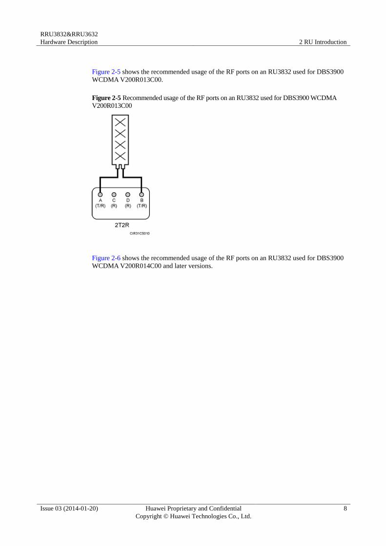
Figure 2-5 shows the recommended usage of the RF ports on an RU3832 used for DBS3900
WCDMA V200R013C00.
Figure 2-5 Recommended usage of the RF ports on an RU3832 used for DBS3900 WCDMA
V200R013C00
Figure 2-6 shows the recommended usage of the RF ports on an RU3832 used for DBS3900
WCDMA V200R014C00 and later versions.
RRU3832&RRU3632
Hardware Description 2 RU Introduction
Issue 03 (2014-01-20) Huawei Proprietary and Confidential
Copyright © Huawei Technologies Co., Ltd.
9
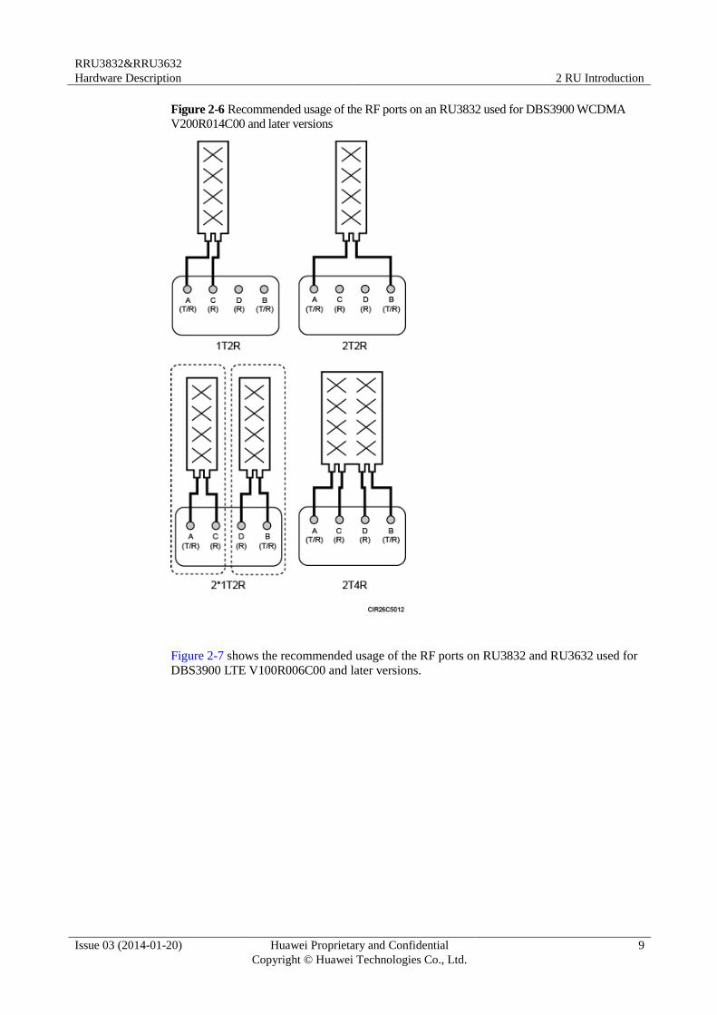
Figure 2-6 Recommended usage of the RF ports on an RU3832 used for DBS3900 WCDMA
V200R014C00 and later versions
Figure 2-7 shows the recommended usage of the RF ports on RU3832 and RU3632 used for
DBS3900 LTE V100R006C00 and later versions.
RRU3832&RRU3632
Hardware Description 2 RU Introduction
Issue 03 (2014-01-20) Huawei Proprietary and Confidential
Copyright © Huawei Technologies Co., Ltd.
10
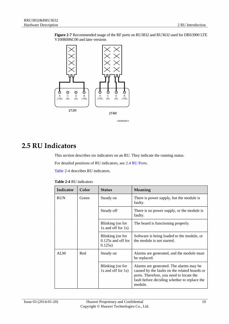
Figure 2-7 Recommended usage of the RF ports on RU3832 and RU3632 used for DBS3900 LTE
V100R006C00 and later versions
2.5 RU Indicators
This section describes six indicators on an RU. They indicate the running status.
For detailed positions of RU indicators, see 2.4 RU Ports.
Table 2-4 describes RU indicators.
Table 2-4 RU indicators
Indicator Color Status Meaning
RUN Green Steady on There is power supply, but the module is
faulty.
Steady off There is no power supply, or the module is
faulty.
Blinking (on for
1s and off for 1s)
The board is functioning properly.
Blinking (on for
0.125s and off for
0.125s)
Software is being loaded to the module, or
the module is not started.
ALM Red Steady on Alarms are generated, and the module must
be replaced.
Blinking (on for
1s and off for 1s)
Alarms are generated. The alarms may be
caused by the faults on the related boards or
ports. Therefore, you need to locate the
fault before deciding whether to replace the module.
RRU3832&RRU3632
Hardware Description 2 RU Introduction
Issue 03 (2014-01-20) Huawei Proprietary and Confidential
Copyright © Huawei Technologies Co., Ltd.
11
Indicator Color Status Meaning
Steady off No alarm is generated.
ACT Green Steady on The module is running properly with TX
channels enabled or the software is being
loaded without RU running.
Blinking (on for
1s and off for 1s)
The module is running properly with TX
channels disabled.
VSWR Red Steady off No Voltage Standing Wave Ratio (VSWR)
alarm is generated.
Blinking (on for
1s and off for 1s)
VSWR alarms are generated on the
ANT_TX/RXB port.
Steady on VSWR alarms are generated on the
ANT_TX/RXA port.
Blinking (on for
0.125s and off for
0.125s)
VSWR alarms are generated on the
ANT_TX/RXA and ANT_TX/RXB ports.
CPRI0 Red or
green
Steady green The CPRI link is functioning properly.
Steady red An optical module fails to transmit or
receive signals because the optical module
is faulty or the fiber optic cable is broken.
Blinking red (on
for 1s and off for
1s)
The CPRI link is out of lock because of a
failure in clock lock between two modes or
mismatched data rates over CPRI ports.
Steady off The optical module cannot be detected, or
the optical module is powered off.
CPRI1 Red or
green
Steady green The CPRI link is functioning properly.
Steady red An optical module fails to transmit or
receive signals because the optical module
is faulty or the fiber optic cable is broken.
Blinking red (on
for 1s and off for
1s)
The CPRI link is out of lock because of a
failure in clock lock between two modes or
mismatched data rates over CPRI ports.
Steady off The optical module cannot be detected, or
the optical module is powered off.
2.6 Optical Modules
An optical module transmits optical signals between an optical port and a fiber optic cable.
RRU3832&RRU3632
Hardware Description 2 RU Introduction
Issue 03 (2014-01-20) Huawei Proprietary and Confidential
Copyright © Huawei Technologies Co., Ltd.
12
The exteriors of an optical module and the label on an optical module in this section are for reference
only. The actual exteriors may be different.
Exterior
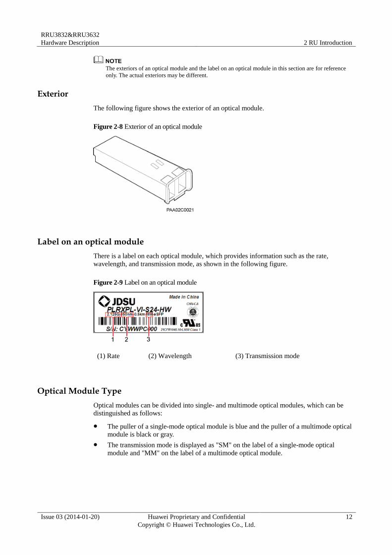
The following figure shows the exterior of an optical module.
Figure 2-8 Exterior of an optical module
Label on an optical module
There is a label on each optical module, which provides information such as the rate,
wavelength, and transmission mode, as shown in the following figure.
Figure 2-9 Label on an optical module
(1) Rate (2) Wavelength (3) Transmission mode
Optical Module Type
Optical modules can be divided into single- and multimode optical modules, which can be
distinguished as follows:
The puller of a single-mode optical module is blue and the puller of a multimode optical
module is black or gray.
The transmission mode is displayed as "SM" on the label of a single-mode optical
module and "MM" on the label of a multimode optical module.
RRU3832&RRU3632
Hardware Description 3 RU Cables
Issue 03 (2014-01-20) Huawei Proprietary and Confidential
Copyright © Huawei Technologies Co., Ltd.
13
3 RU Cables
About This Chapter
This chapter describes RU cables.
3.1 RU Cable List
This section describes RU cable connections.
3.2 RU PGND Cable
An RU PGND cable connects an RU and a ground bar, ensuring the proper grounding of the
RU. The maximum length of an RU PGND cable is 8 m (26.25 ft).
3.3 RU Power Cable
The RU power cable is a -48 V DC shielded cable. It feeds -48 V DC power to an RU. The
length of power supply that an RU power cable supports is 100 m (328.08 ft) by default.
3.4 RU Alarm Cable
The RU alarm cable, a shielded straight-through cable, transmits alarm signals from an
external device to an RU so that the base station monitors the operating status of external
devices. The RU alarm cable is 5 m (16.4 ft).
3.5 CPRI Fiber Optic Cable
CPRI fiber optic cables are classified into multimode fiber optic cables and single-mode fiber
optic cables. They transmit CPRI signals.
3.6 RU RF Jumper
The 1/2" RU RF jumper transmits and receives RF signals between an RU and an antenna. A
fixed-length RF jumper used by an RU is 2 m (6.56 ft), 3 m (9.84 ft), 4 m (13.12 ft), 6 m
(19.68 ft), or 10 m (32.81 ft). A variable-length RF jumper used by an RU has a maximum
length of 10 m (32.81 ft).
3.7 RU AISG Multi-Wire Cable
An RU AISG multi-wire cable connects an RU and an RCU to transmit control signals from a
base station to an RET antenna. When the RU is connected to the RET antenna, an AISG
multi-wire cable transmits RS485 signals. The length of the AISG multi-wire cable is 5 m
(16.40 ft).
3.8 RU AISG Extension Cable
RRU3832&RRU3632
Hardware Description 3 RU Cables
Issue 03 (2014-01-20) Huawei Proprietary and Confidential
Copyright © Huawei Technologies Co., Ltd.
14
When the distance between an RU and an RCU is longer than 5 m (16.4 ft), an AISG
multi-wire cable is not long enough to connect the RU and the RCU. In this case, an AISG
extension cable is used to extend the AISG multi-wire cable for transmitting RS485 signals.
The length of the AISG extension cable is 15 m (49.21 ft).
3.1 RU Cable List
This section describes RU cable connections.
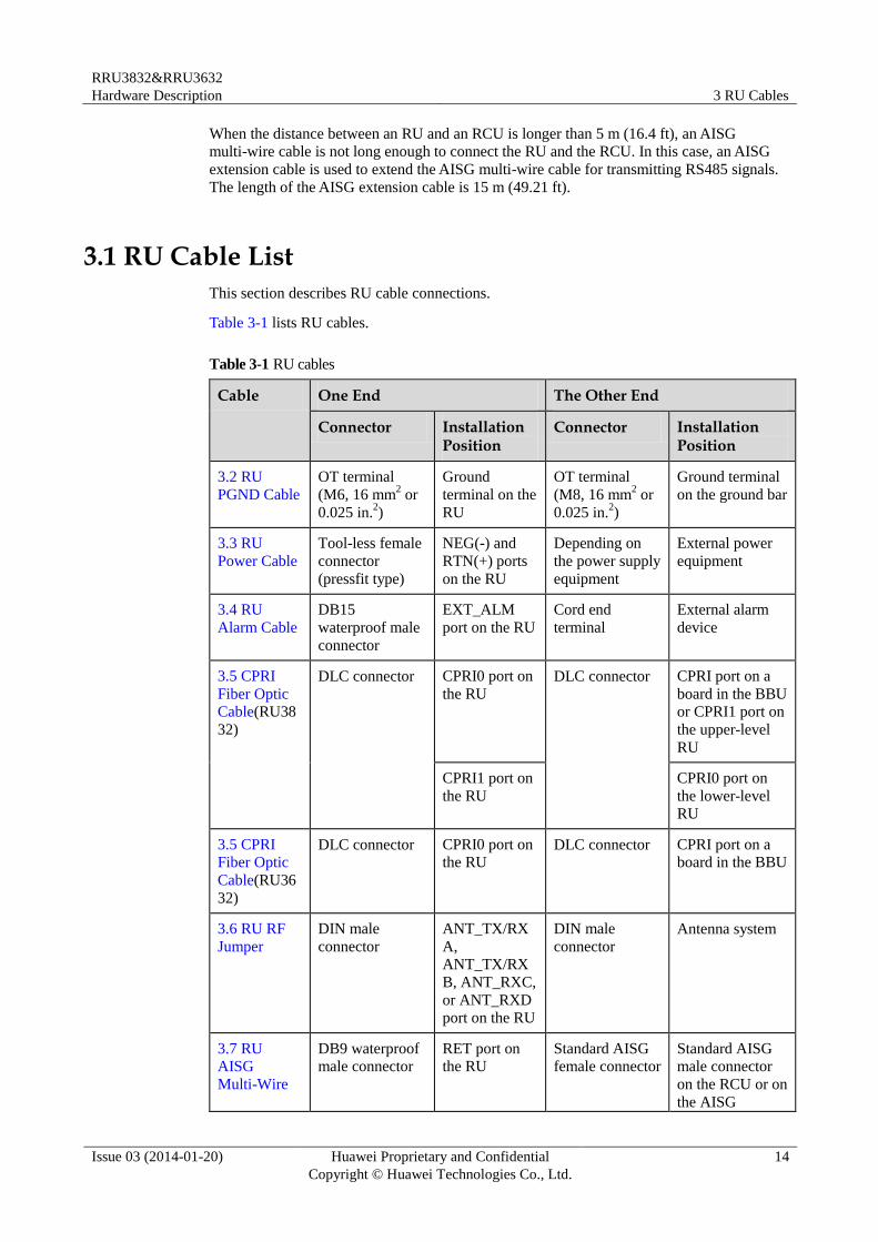
Table 3-1 lists RU cables.
Table 3-1 RU cables
Cable One End The Other End
Connector Installation Position
Connector Installation Position
3.2 RU
PGND Cable
OT terminal
(M6, 16 mm2 or
0.025 in.2)
Ground
terminal on the
RU
OT terminal
(M8, 16 mm2 or
0.025 in.2)
Ground terminal
on the ground bar
3.3 RU
Power Cable
Tool-less female
connector
(pressfit type)
NEG(-) and
RTN(+) ports
on the RU
Depending on
the power supply
equipment
External power
equipment
3.4 RU
Alarm Cable
DB15
waterproof male
connector
EXT_ALM
port on the RU
Cord end
terminal
External alarm
device
3.5 CPRI
Fiber Optic
Cable(RU38
32)
DLC connector CPRI0 port on
the RU
DLC connector CPRI port on a
board in the BBU
or CPRI1 port on
the upper-level
RU
CPRI1 port on
the RU
CPRI0 port on
the lower-level
RU
3.5 CPRI
Fiber Optic
Cable(RU36
32)
DLC connector CPRI0 port on
the RU DLC connector CPRI port on a
board in the BBU
3.6 RU RF
Jumper
DIN male
connector
ANT_TX/RX
A,
ANT_TX/RX
B, ANT_RXC,
or ANT_RXD
port on the RU
DIN male
connector
Antenna system
3.7 RU
AISG
Multi-Wire
DB9 waterproof
male connector
RET port on
the RU
Standard AISG
female connector
Standard AISG
male connector
on the RCU or on
the AISG
RRU3832&RRU3632
Hardware Description 3 RU Cables
Issue 03 (2014-01-20) Huawei Proprietary and Confidential
Copyright © Huawei Technologies Co., Ltd.
15
Cable One End The Other End
Connector Installation Position
Connector Installation Position
Cable extension cable
3.8 RU
AISG
Extension
Cable
Standard AISG
male connector
Standard AISG
female
connector on
the AISG
multi-wire
cable
Standard AISG
female connector
Standard AISG
male connector
on the RCU
3.2 RU PGND Cable
An RU PGND cable connects an RU and a ground bar, ensuring the proper grounding of the
RU. The maximum length of an RU PGND cable is 8 m (26.25 ft).
Exterior
A PGND cable is green or green and yellow with a cross-sectional area of 16 mm2 (0.025 in.
2).
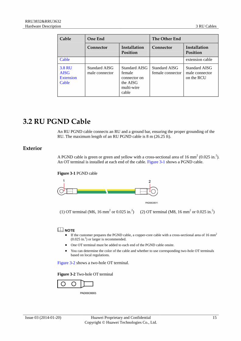
An OT terminal is installed at each end of the cable. Figure 3-1 shows a PGND cable.
Figure 3-1 PGND cable
(1) OT terminal (M6, 16 mm2 or 0.025 in.
2) (2) OT terminal (M8, 16 mm
2 or 0.025 in.
2)
If the customer prepares the PGND cable, a copper-core cable with a cross-sectional area of 16 mm2
(0.025 in.2) or larger is recommended.
One OT terminal must be added to each end of the PGND cable onsite.
You can determine the color of the cable and whether to use corresponding two-hole OT terminals
based on local regulations.
Figure 3-2 shows a two-hole OT terminal.
Figure 3-2 Two-hole OT terminal
RRU3832&RRU3632
Hardware Description 3 RU Cables
Issue 03 (2014-01-20) Huawei Proprietary and Confidential
Copyright © Huawei Technologies Co., Ltd.
16
3.3 RU Power Cable
The RU power cable is a -48 V DC shielded cable. It feeds -48 V DC power to an RU. The
length of power supply that an RU power cable supports is 100 m (328.08 ft) by default.
The maximum length of power supply that an RU power cable supports is 150 m (492.12 ft).
Contact Huawei engineers when an RU power cable greater than 50 m (164.04 ft) is required.
If a power device provided by the customer is used, the recommended specification of the circuit
breaker on this power device is 15 A to 30 A.
Exterior
There are four types of RU power cables in terms of cross-sectional areas: 3.3 mm2 (0.005 in.
2)
(12 AWG) and 5.3 mm2 (0.008 in.
2) (10 AWG) complying with North American standards,
and 4 mm2 (0.006 in.
2) and 6 mm
2 (0.009 in.
2) complying with European standards.
A tool-less female connector (pressfit type) needs to be added to one end of the RU power
cable and a corresponding terminal needs to be added to the other end based on the
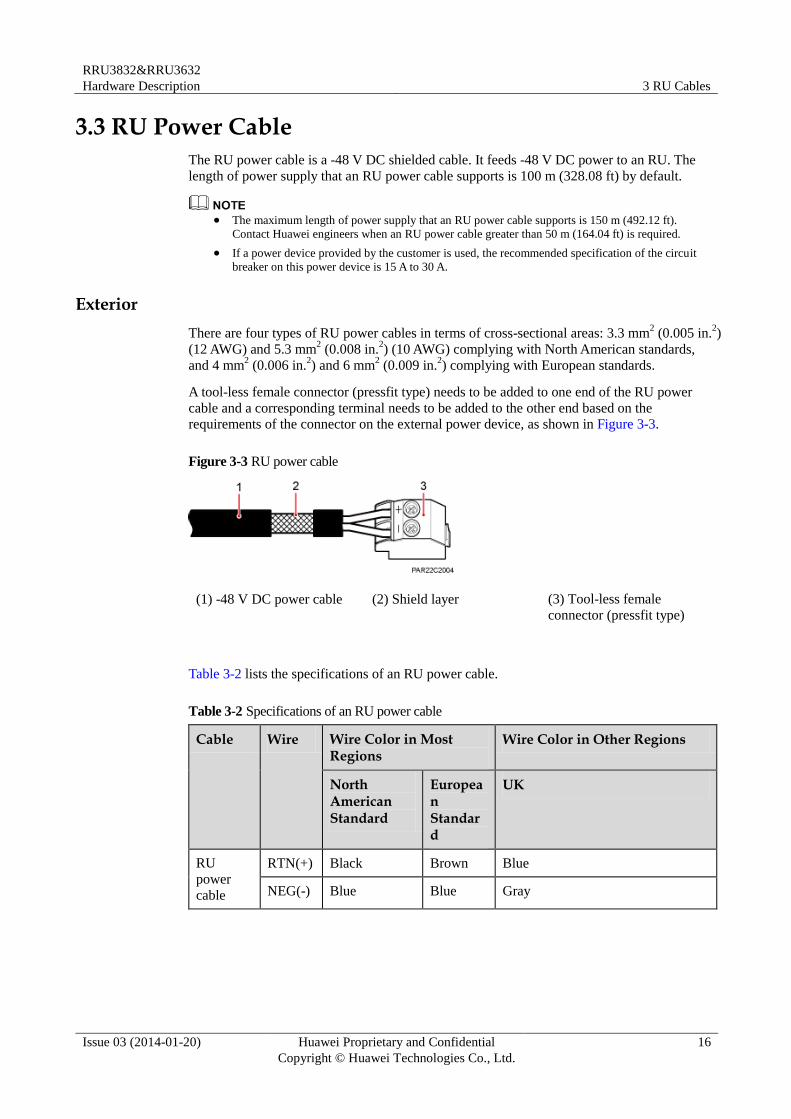
requirements of the connector on the external power device, as shown in Figure 3-3.
Figure 3-3 RU power cable
(1) -48 V DC power cable (2) Shield layer (3) Tool-less female
connector (pressfit type)
Table 3-2 lists the specifications of an RU power cable.
Table 3-2 Specifications of an RU power cable
Cable Wire Wire Color in Most Regions
Wire Color in Other Regions
North American Standard
European Standard
UK
RU
power
cable
RTN(+) Black Brown Blue
NEG(-) Blue Blue Gray
RRU3832&RRU3632
Hardware Description 3 RU Cables
Issue 03 (2014-01-20) Huawei Proprietary and Confidential
Copyright © Huawei Technologies Co., Ltd.
17
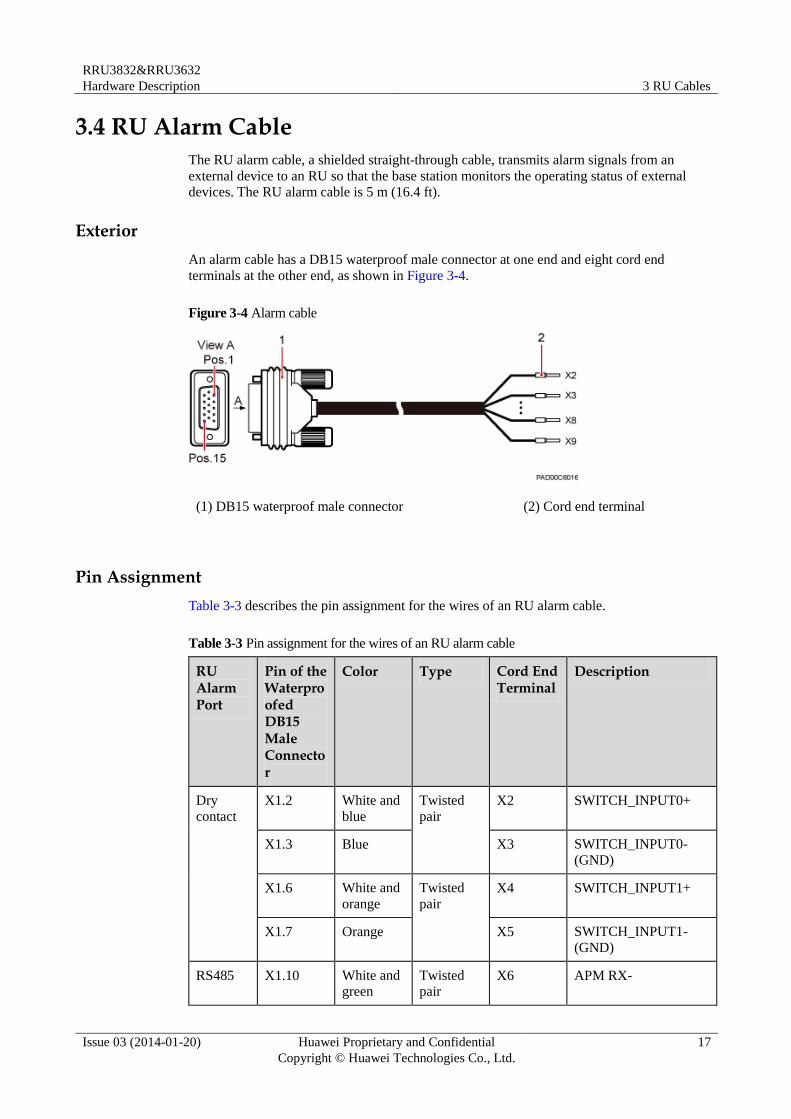
3.4 RU Alarm Cable
The RU alarm cable, a shielded straight-through cable, transmits alarm signals from an
external device to an RU so that the base station monitors the operating status of external
devices. The RU alarm cable is 5 m (16.4 ft).
Exterior
An alarm cable has a DB15 waterproof male connector at one end and eight cord end
terminals at the other end, as shown in Figure 3-4.
Figure 3-4 Alarm cable
(1) DB15 waterproof male connector (2) Cord end terminal
Pin Assignment
Table 3-3 describes the pin assignment for the wires of an RU alarm cable.
Table 3-3 Pin assignment for the wires of an RU alarm cable
RU Alarm Port
Pin of the Waterproofed DB15 Male Connector
Color Type Cord End Terminal
Description
Dry
contact
X1.2 White and
blue
Twisted
pair
X2 SWITCH_INPUT0+
X1.3 Blue X3 SWITCH_INPUT0-
(GND)
X1.6 White and
orange
Twisted
pair
X4 SWITCH_INPUT1+
X1.7 Orange X5 SWITCH_INPUT1-
(GND)
RS485 X1.10 White and green
Twisted pair
X6 APM RX-
RRU3832&RRU3632
Hardware Description 3 RU Cables
Issue 03 (2014-01-20) Huawei Proprietary and Confidential
Copyright © Huawei Technologies Co., Ltd.
18
RU Alarm Port
Pin of the Waterproofed DB15 Male Connector
Color Type Cord End Terminal
Description
X1.11 Green X7 APM RX+
X1.13 White and
brown
Twisted
pair
X8 APM TX-
X1.14 Brown X9 APM TX+
3.5 CPRI Fiber Optic Cable
CPRI fiber optic cables are classified into multimode fiber optic cables and single-mode fiber
optic cables. They transmit CPRI signals.
Multimode fiber optic cables connect the BBU and RU or interconnect two RUs. The
maximum length of the multimode fiber optic cable between the BBU and RU is 150 m
(492.12 ft) and the multimode fiber optic cable between two RUs has a fixed length of 10 m
(32.81 ft).
A single-mode fiber optic cable consists of the single-mode pigtail and trunk single-mode
fiber optic cable, and the single-mode pigtail and trunk single-mode fiber optic cable are
interconnected using the ODF. The maximum length of the single-mode pigtail is 20 m (65.62
ft) on BBU side and 70 m (229.66 ft) on RU side.
The ODF and trunk single-mode fiber optic cable are provided by the customer and must comply
with the ITU-T G.652 standard.
The ODF is an outdoor transfer box for fiber optic cables, which interconnects the single-mode
pigtail and trunk single-mode fiber optic cable.
A multimode fiber optic cable and a single-mode fiber optic cable are connected to a multimode
optical module and a single-mode optical module, respectively.
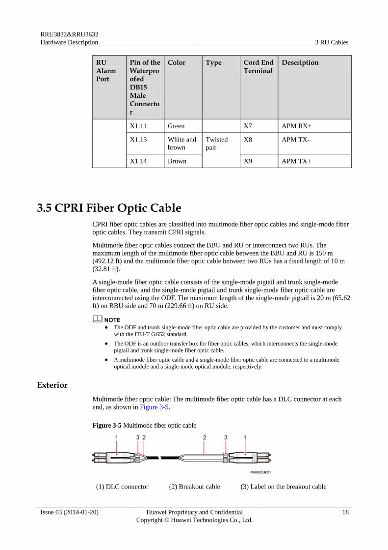
Exterior
Multimode fiber optic cable: The multimode fiber optic cable has a DLC connector at each
end, as shown in Figure 3-5.
Figure 3-5 Multimode fiber optic cable
(1) DLC connector (2) Breakout cable (3) Label on the breakout cable
RRU3832&RRU3632
Hardware Description 3 RU Cables
Issue 03 (2014-01-20) Huawei Proprietary and Confidential
Copyright © Huawei Technologies Co., Ltd.
19
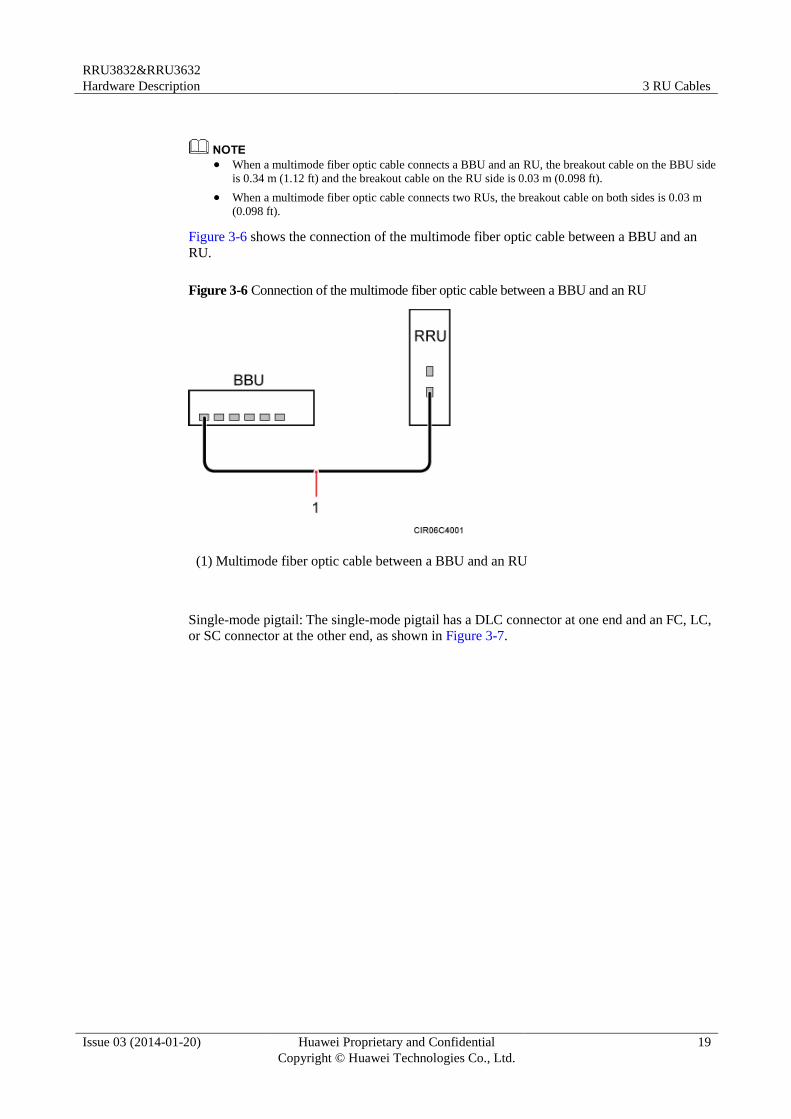
When a multimode fiber optic cable connects a BBU and an RU, the breakout cable on the BBU side
is 0.34 m (1.12 ft) and the breakout cable on the RU side is 0.03 m (0.098 ft).
When a multimode fiber optic cable connects two RUs, the breakout cable on both sides is 0.03 m
(0.098 ft).
Figure 3-6 shows the connection of the multimode fiber optic cable between a BBU and an
RU.
Figure 3-6 Connection of the multimode fiber optic cable between a BBU and an RU
(1) Multimode fiber optic cable between a BBU and an RU
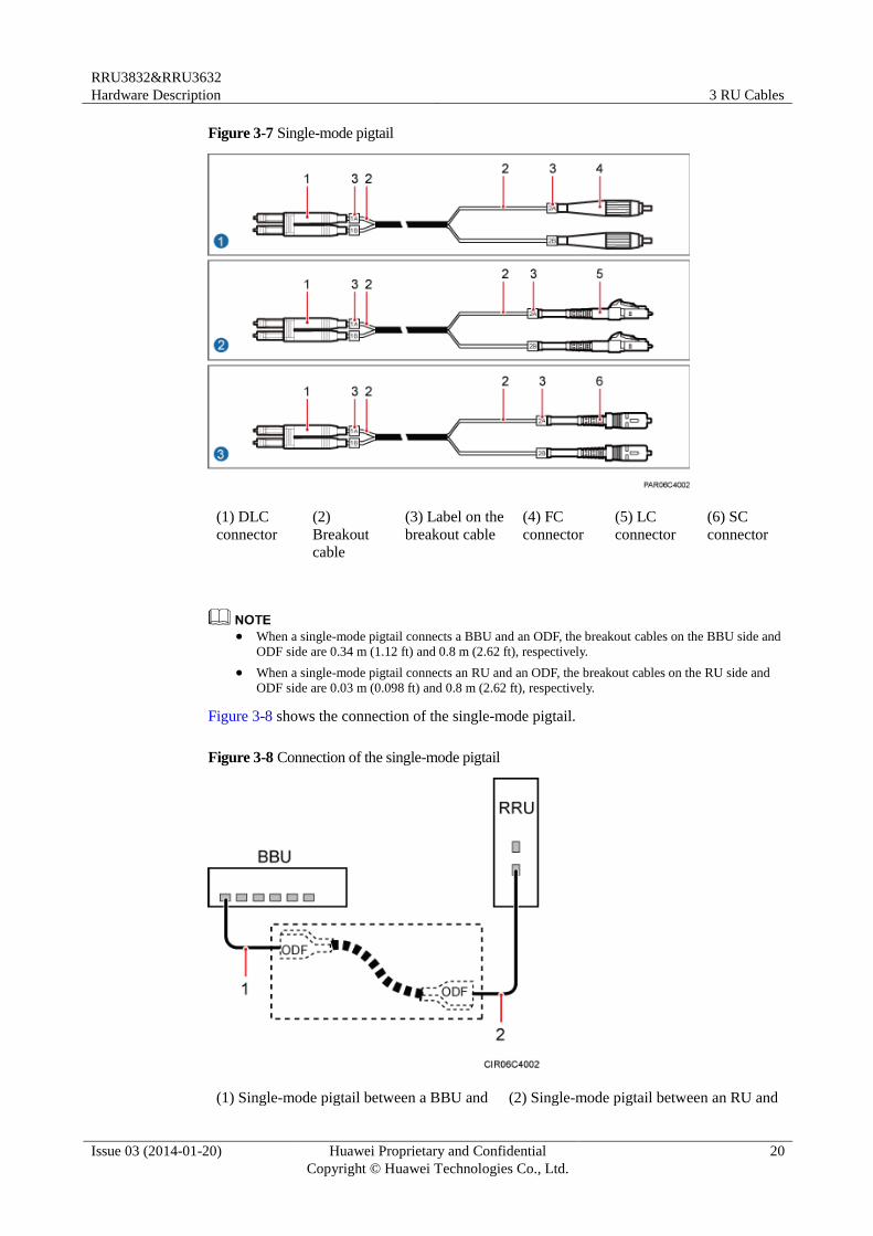
Single-mode pigtail: The single-mode pigtail has a DLC connector at one end and an FC, LC,
or SC connector at the other end, as shown in Figure 3-7.
RRU3832&RRU3632
Hardware Description 3 RU Cables
Issue 03 (2014-01-20) Huawei Proprietary and Confidential
Copyright © Huawei Technologies Co., Ltd.
20
Figure 3-7 Single-mode pigtail
(1) DLC
connector
(2)
Breakout
cable
(3) Label on the
breakout cable
(4) FC
connector
(5) LC
connector
(6) SC
connector
When a single-mode pigtail connects a BBU and an ODF, the breakout cables on the BBU side and
ODF side are 0.34 m (1.12 ft) and 0.8 m (2.62 ft), respectively.
When a single-mode pigtail connects an RU and an ODF, the breakout cables on the RU side and
ODF side are 0.03 m (0.098 ft) and 0.8 m (2.62 ft), respectively.
Figure 3-8 shows the connection of the single-mode pigtail.
Figure 3-8 Connection of the single-mode pigtail
(1) Single-mode pigtail between a BBU and (2) Single-mode pigtail between an RU and
RRU3832&RRU3632
Hardware Description 3 RU Cables
Issue 03 (2014-01-20) Huawei Proprietary and Confidential
Copyright © Huawei Technologies Co., Ltd.
21
an ODF an ODF
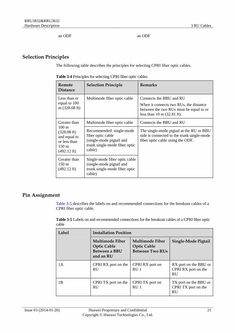
Selection Principles
The following table describes the principles for selecting CPRI fiber optic cables.
Table 3-4 Principles for selecting CPRI fiber optic cables
Remote Distance
Selection Principle Remarks
Less than or
equal to 100
m (328.08 ft)
Multimode fiber optic cable Connects the BBU and RU
When it connects two RUs, the distance
between the two RUs must be equal to or
less than 10 m (32.81 ft).
Greater than
100 m
(328.08 ft)
and equal to
or less than
150 m
(492.12 ft)
Multimode fiber optic cable Connects the BBU and RU
Recommended: single-mode
fiber optic cable
(single-mode pigtail and
trunk single-mode fiber optic
cable)
The single-mode pigtail at the RU or BBU
side is connected to the trunk single-mode
fiber optic cable using the ODF.
Greater than
150 m
(492.12 ft)
Single-mode fiber optic cable
(single-mode pigtail and
trunk single-mode fiber optic
cable)
Pin Assignment
Table 3-5 describes the labels on and recommended connections for the breakout cables of a
CPRI fiber optic cable.
Table 3-5 Labels on and recommended connections for the breakout cables of a CPRI fiber optic
cable
Label Installation Position
Multimode Fiber Optic Cable Between a BBU and an RU
Multimode Fiber Optic Cable Between Two RUs
Single-Mode Pigtail
1A CPRI RX port on the
RU
CPRI RX port on
RU 1
RX port on the BBU or
CPRI RX port on the
RU
1B CPRI TX port on the
RU
CPRI TX port on
RU 1
TX port on the BBU or
CPRI TX port on the
RU
RRU3832&RRU3632
Hardware Description 3 RU Cables
Issue 03 (2014-01-20) Huawei Proprietary and Confidential
Copyright © Huawei Technologies Co., Ltd.
22
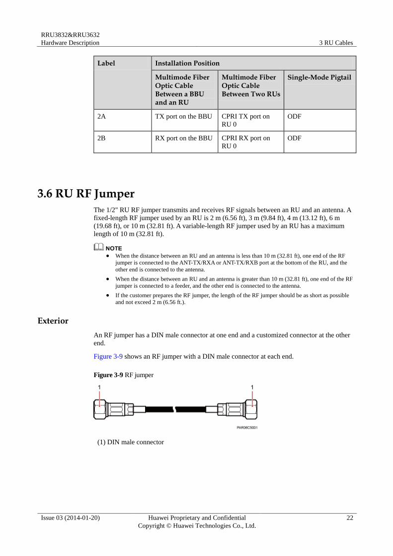
Label Installation Position
Multimode Fiber Optic Cable Between a BBU and an RU
Multimode Fiber Optic Cable Between Two RUs
Single-Mode Pigtail
2A TX port on the BBU CPRI TX port on
RU 0
ODF
2B RX port on the BBU CPRI RX port on
RU 0
ODF
3.6 RU RF Jumper
The 1/2" RU RF jumper transmits and receives RF signals between an RU and an antenna. A
fixed-length RF jumper used by an RU is 2 m (6.56 ft), 3 m (9.84 ft), 4 m (13.12 ft), 6 m
(19.68 ft), or 10 m (32.81 ft). A variable-length RF jumper used by an RU has a maximum
length of 10 m (32.81 ft).
When the distance between an RU and an antenna is less than 10 m (32.81 ft), one end of the RF
jumper is connected to the ANT-TX/RXA or ANT-TX/RXB port at the bottom of the RU, and the
other end is connected to the antenna.
When the distance between an RU and an antenna is greater than 10 m (32.81 ft), one end of the RF
jumper is connected to a feeder, and the other end is connected to the antenna.
If the customer prepares the RF jumper, the length of the RF jumper should be as short as possible
and not exceed 2 m (6.56 ft.).
Exterior
An RF jumper has a DIN male connector at one end and a customized connector at the other
end.
Figure 3-9 shows an RF jumper with a DIN male connector at each end.
Figure 3-9 RF jumper
(1) DIN male connector
RRU3832&RRU3632
Hardware Description 3 RU Cables
Issue 03 (2014-01-20) Huawei Proprietary and Confidential
Copyright © Huawei Technologies Co., Ltd.
23
3.7 RU AISG Multi-Wire Cable
An RU AISG multi-wire cable connects an RU and an RCU to transmit control signals from a
base station to an RET antenna. When the RU is connected to the RET antenna, an AISG
multi-wire cable transmits RS485 signals. The length of the AISG multi-wire cable is 5 m
(16.40 ft).
An RCU is a driving motor used for the phase shifter in the RET antenna. It receives control commands
from a base station and runs the commands to drive the stepper motor. Using a gear, the stepper motor
drives the adjustable phase shifter in the antenna and changes the downtilt angle.
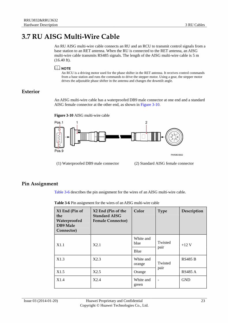
Exterior
An AISG multi-wire cable has a waterproofed DB9 male connector at one end and a standard
AISG female connector at the other end, as shown in Figure 3-10.
Figure 3-10 AISG multi-wire cable
(1) Waterproofed DB9 male connector (2) Standard AISG female connector
Pin Assignment
Table 3-6 describes the pin assignment for the wires of an AISG multi-wire cable.
Table 3-6 Pin assignment for the wires of an AISG multi-wire cable
X1 End (Pin of the Waterproofed DB9 Male Connector)
X2 End (Pin of the Standard AISG Female Connector)
Color Type Description
X1.1 X2.1
White and
blue Twisted
pair +12 V
Blue
X1.3 X2.3 White and
orange Twisted
pair
RS485 B
X1.5 X2.5 Orange RS485 A
X1.4 X2.4 White and
green - GND
RRU3832&RRU3632
Hardware Description 3 RU Cables
Issue 03 (2014-01-20) Huawei Proprietary and Confidential
Copyright © Huawei Technologies Co., Ltd.
24
X1 End (Pin of the Waterproofed DB9 Male Connector)
X2 End (Pin of the Standard AISG Female Connector)
Color Type Description
X1.9 and X1.4 are
interconnected.
- - - GND
- X2.1 and X2.6 are
interconnected. - - +12 V
- X2.4 and X2.7 are
interconnected.
- - GND
3.8 RU AISG Extension Cable
When the distance between an RU and an RCU is longer than 5 m (16.4 ft), an AISG
multi-wire cable is not long enough to connect the RU and the RCU. In this case, an AISG
extension cable is used to extend the AISG multi-wire cable for transmitting RS485 signals.
The length of the AISG extension cable is 15 m (49.21 ft).
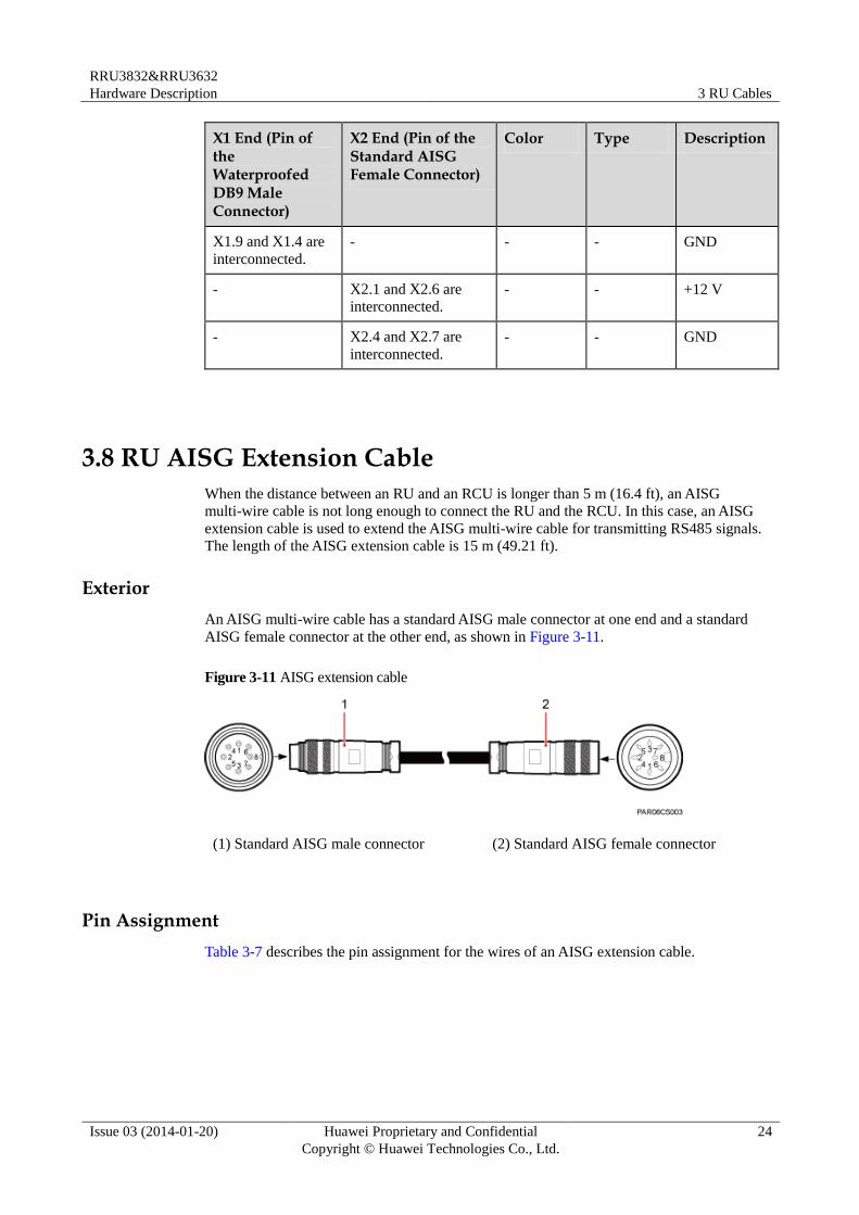
Exterior
An AISG multi-wire cable has a standard AISG male connector at one end and a standard
AISG female connector at the other end, as shown in Figure 3-11.
Figure 3-11 AISG extension cable
(1) Standard AISG male connector (2) Standard AISG female connector
Pin Assignment
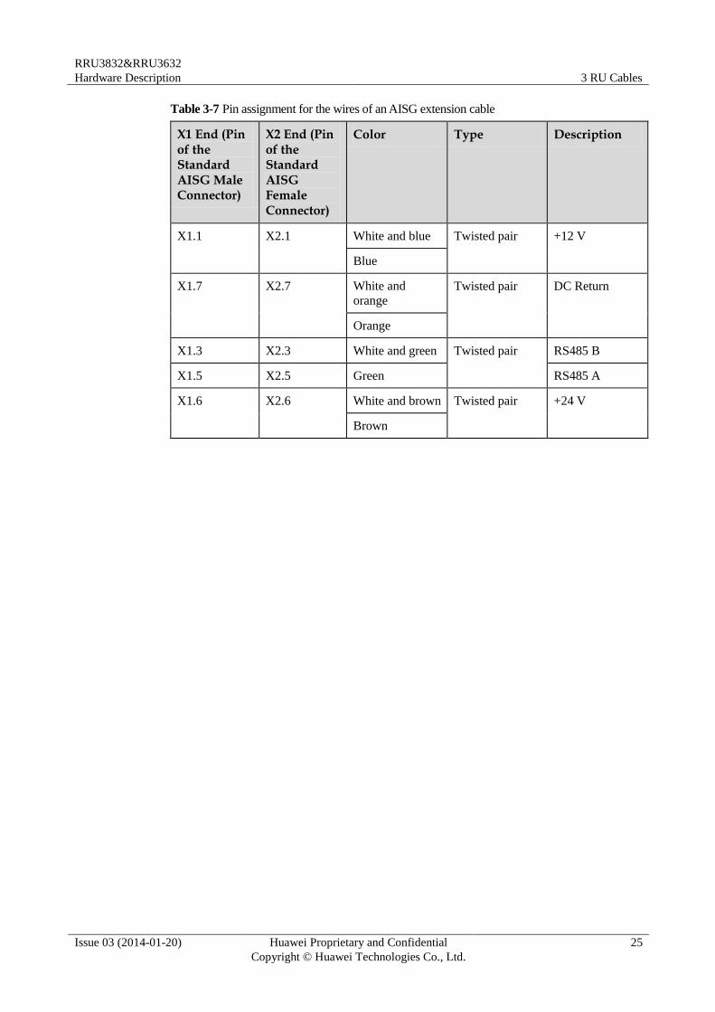
Table 3-7 describes the pin assignment for the wires of an AISG extension cable.
RRU3832&RRU3632
Hardware Description 3 RU Cables
Issue 03 (2014-01-20) Huawei Proprietary and Confidential
Copyright © Huawei Technologies Co., Ltd.
25
Table 3-7 Pin assignment for the wires of an AISG extension cable
X1 End (Pin of the Standard AISG Male Connector)
X2 End (Pin of the Standard AISG Female Connector)
Color Type Description
X1.1 X2.1 White and blue Twisted pair +12 V
Blue
X1.7 X2.7 White and
orange
Twisted pair DC Return
Orange
X1.3 X2.3 White and green Twisted pair RS485 B
X1.5 X2.5 Green RS485 A
X1.6 X2.6 White and brown Twisted pair +24 V
Brown
RRU3832&RRU3632
Hardware Description 4 RF Cable Connections for the RU3832&RU3632
Issue 03 (2014-01-20) Huawei Proprietary and Confidential
Copyright © Huawei Technologies Co., Ltd.
26
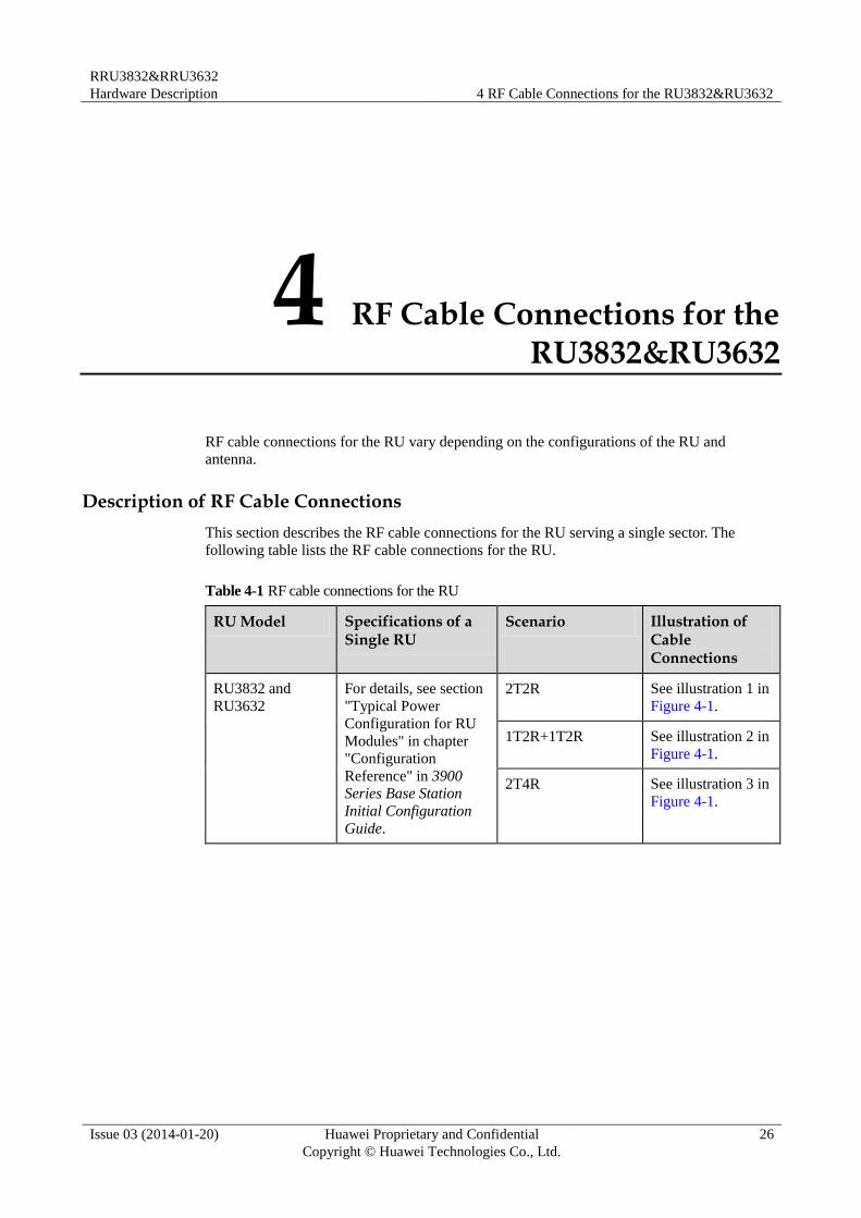
4 RF Cable Connections for the RU3832&RU3632
RF cable connections for the RU vary depending on the configurations of the RU and
antenna.
Description of RF Cable Connections
This section describes the RF cable connections for the RU serving a single sector. The
following table lists the RF cable connections for the RU.
Table 4-1 RF cable connections for the RU
RU Model Specifications of a Single RU
Scenario Illustration of Cable Connections
RU3832 and
RU3632
For details, see section
"Typical Power
Configuration for RU
Modules" in chapter
"Configuration
Reference" in 3900 Series Base Station
Initial Configuration
Guide.
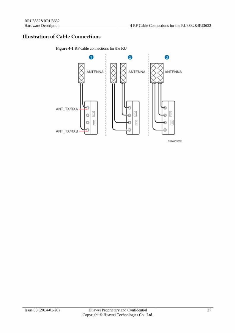
2T2R See illustration 1 in
Figure 4-1.
1T2R+1T2R See illustration 2 in
Figure 4-1.
2T4R See illustration 3 in
Figure 4-1.
RRU3832&RRU3632
Hardware Description 4 RF Cable Connections for the RU3832&RU3632
Issue 03 (2014-01-20) Huawei Proprietary and Confidential
Copyright © Huawei Technologies Co., Ltd.
27
Illustration of Cable Connections
Figure 4-1 RF cable connections for the RU
RRU3832&RRU3632
Hardware Description 5 RU Auxiliary Devices
Issue 03 (2014-01-20) Huawei Proprietary and Confidential
Copyright © Huawei Technologies Co., Ltd.
28
5 RU Auxiliary Devices
About This Chapter
This chapter describes RU auxiliary devices.
5.1 IFS06
An Indoor Floor installation Support (IFS06) is used for installing indoor RUs.
5.2 OCB
An Outdoor Cable Conversion Box (OCB) interconnects cables of different core diameters.
Power cables shipped with RUs cannot support long-distance power supply. Therefore, when
power supply is far from the equipment, cables with large core diameters are used, and an
OCB connects these cables and RU power cables.
5.1 IFS06
An Indoor Floor installation Support (IFS06) is used for installing indoor RUs.
Exterior
Figure 5-1 shows an IFS06.
RRU3832&RRU3632
Hardware Description 5 RU Auxiliary Devices
Issue 03 (2014-01-20) Huawei Proprietary and Confidential
Copyright © Huawei Technologies Co., Ltd.
29
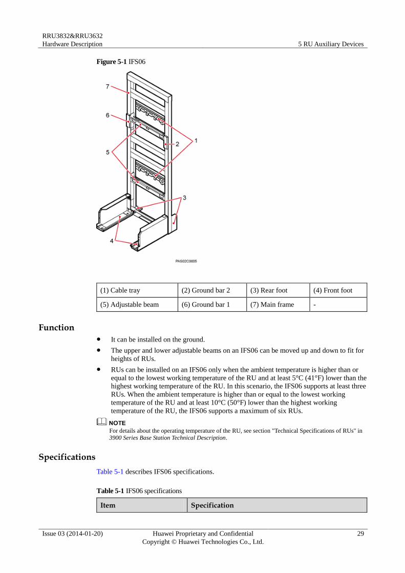
Figure 5-1 IFS06
(1) Cable tray (2) Ground bar 2 (3) Rear foot (4) Front foot
(5) Adjustable beam (6) Ground bar 1 (7) Main frame -
Function It can be installed on the ground.
The upper and lower adjustable beams on an IFS06 can be moved up and down to fit for
heights of RUs.
RUs can be installed on an IFS06 only when the ambient temperature is higher than or
equal to the lowest working temperature of the RU and at least 5°C (41°F) lower than the
highest working temperature of the RU. In this scenario, the IFS06 supports at least three
RUs. When the ambient temperature is higher than or equal to the lowest working
temperature of the RU and at least 10°C (50°F) lower than the highest working
temperature of the RU, the IFS06 supports a maximum of six RUs.
For details about the operating temperature of the RU, see section "Technical Specifications of RUs" in
3900 Series Base Station Technical Description.
Specifications
Table 5-1 describes IFS06 specifications.
Table 5-1 IFS06 specifications
Item Specification
RRU3832&RRU3632
Hardware Description 5 RU Auxiliary Devices
Issue 03 (2014-01-20) Huawei Proprietary and Confidential
Copyright © Huawei Technologies Co., Ltd.
30
Item Specification
Dimensions (H x W x D) 1730 mm (79 in.) x 600 mm (23.62 in.) x 600 mm (23.62
in.)
Weight 45 kg (99.23 lb)
5.2 OCB
An Outdoor Cable Conversion Box (OCB) interconnects cables of different core diameters.
Power cables shipped with RUs cannot support long-distance power supply. Therefore, when
power supply is far from the equipment, cables with large core diameters are used, and an
OCB connects these cables and RU power cables.
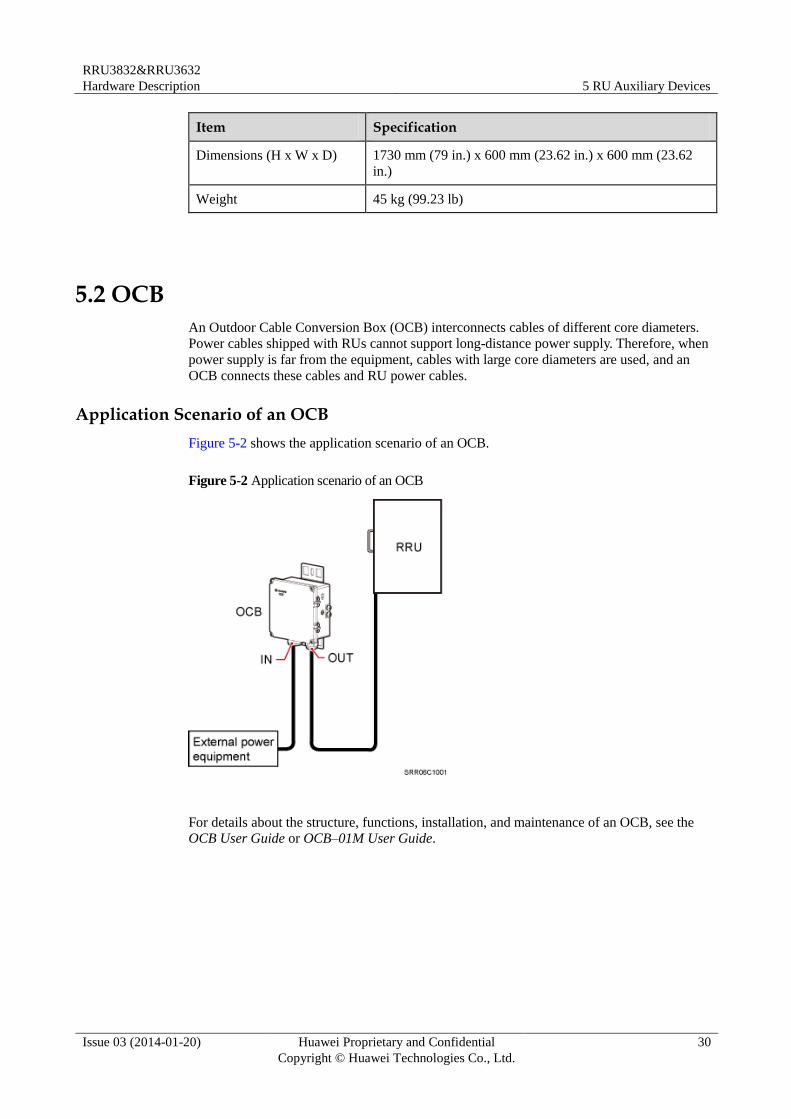
Application Scenario of an OCB
Figure 5-2 shows the application scenario of an OCB.
Figure 5-2 Application scenario of an OCB
For details about the structure, functions, installation, and maintenance of an OCB, see the
OCB User Guide or OCB–01M User Guide.