Embed Size (px)
Citation preview
Hardware architecture for ellipticcurve cryptography and lossless
data compression
by
Miguel Morales-Sandoval
A thesis
presented to the National Institute for Astrophysics, Optics and Electronicsin partial fulfilment of the
requirement for the degree of
Master of Computer Science
Thesis Advisor:PhD. Claudia Feregrino-Uribe
Computer Science DepartmentNational Institute for Astrophysics, Optics and Electronics
Tonantzintla, PueblaMexico
December 2004
Abstract
Data compression and cryptography play an important role when transmitting dataacross a public computer network. While compression reduces the amount of data tobe transferred or stored, cryptography ensures that data is transmitted with reliabilityand integrity. Compression and encryption have to be applied in the correct way: dataare compressed before they are encrypted. If it were the opposite case the result of thecryptographic operation would be illegible data and no patterns or redundancy wouldbe present, leading to very poor or no compression. In this research work, a hardwarearchitecture that joins lossless compression and public-key cryptography for secure datatransmission applications is discussed. The architecture consists of a dictionary-basedlossless data compressor to compress the incoming data, and an elliptic curve crypto-graphic module that performs two EC (elliptic curve) cryptographic schemes: encryp-tion and digital signature. For lossless data compression, the dictionary-based LZ77algorithm is implemented using a systolic array aproach. The elliptic curve cryptosys-tem is defined over the binary field F2m , using polynomial basis, affine coordinates andthe binary method to compute an scalar multiplication. While the model of the completesystem was implemented in software, the hardware architecture was described in theVery High Speed Integrated Circuit Hardware Description Language (VHDL). A pro-totype of the architecture was implemented on a Xilinx Virtex II Field ProgrammableGate Array (FPGA) device. Two advantages of combining lossless compression andpublic-key encryption were demonstrated: 1) the improvement in the cryptographicmodule by reducing the amount of data to be encrypted, and 2) a better utilization ofthe available bandwidth when encrypted data is transmitted across a public computernetwork.
i

ii
Resumen
Cryptografıa y compresion de datos son dos tecnologias centrales en aplicaciones dered. La compresion reduce la cantidad de datos permitiendo ahorro de espacio dealmacenamiento o reduccion de tiempo para realizar la tranferencia de los datos. Porotra parte, la criptografıa garantiza que los datos se transmitan con confiabilidad eintegridad. Cuando ambos algoritmos se combinan, la compresion debe ralizarse primeroy a continuacion el cifrado. Si la aplicacion de los algoritmos se realizara en el ordeninverso, el resultado de la operacion de cifrado darıa como resultado datos totalmenteinenteligibles con muy poca o nula redundancia. Cuando la compresion fuera aplicada,el resultado serıa pobre o nula.
En este trabajo de investigacion se presenta una arquitectura hardware que combinacompresion de datos sin perdida y criptografıa de llave publica para aplicaciones detransmision segura de datos. La arquitectura consiste de un compresor de datos sinperdida basado en diccionario y un modulo que ejecuta dos esquemas de criptografıa decurvas elıpticas (ECC): cifrado y firma digital. El metodo de compresion seleccionado esel LZ77 implementado bajo el enfoque de arreglos sistolicos. El criptosistema de curvaselıpticas se define sobre el campo binario F2m usando base polinomial y coordenadasaffine. El metodo binario es utilizado para realizar la operacion de multiplicacion escalar.
Una implementacion en software del sistema propuesto fue realizada a fin de validarla arquitectura hardware. El sistema completo fue descrito usando el lenguaje estandarpara descripcion de hardare VHDL, fue simulado en Active-VHDL y sintetizado para lafamilia de FPGAS (Field Programmable Gate Array) Virtex II de Xilinx. Las ventajasque presenta el enfoque de combinar compresion de datos com criptografıa son: 1) elmejoramiento en el desempeno del modulo criptografico al reducir la cantidad de datosa ser procesados y, 2) una mejor utilizacion del ancho de banda disponible cuando lainformacion se transmite a traves de una red.
iii

iv

Acknowledgements
I want to thank the Consejo Nacional de Ciencia y Tecnologıa (CONACyT) for fi-nancial support through scholarship number 171577. I thank the Instituto Nacional deAtrofısica, Optica y Electronica (INAOE) for academic formation and different supportsand services.
I am grateful to my advisor Dra. Claudia Feregrino-Uribe for her reviews, help,guidance and encouragement in conducting this research. I count myself as being themost fortunate to be able to work under her supervision.
The same acknowledgement should also go to Dr. Rene Cumplido-Parra, Dr. MiguelArias-Estrada and Dr. Guillermo-De Ita-Luna who acted as my graduate committeefor their valuable input.
I wish I would never forget the company I had from my friends at the Institute.In particular, I am thankful to Alberto-Tellez, Moises-Gutierrez, Ignacio-Algredo, Eric-Rodrıguez and Carlos-Diaz.
This thesis might not exist at all without the love and support of my family. Thelove and moral support of my sisters Lucila and Esperanza, my brothers Victor andAlfredo. My mother Anastacia for her love, encouragement and inspiration, I can neverthank her enough. My niece Jasmine has made my life much more cheerful and colorful.
Lastly but not least, thanks are also due to Leticia-Flores and Manuel-Juarez fortheir help and friendship. Many more persons participated in various ways to ensuremy research succeeded than those and I am thankful to them all.
v

To my father†, by his teachings and example.
Contents
Abstract i
Preface ix
1 Introduction 1
1.1 Introduction . . . . . . . . . . . . . . . . . . . . . . . . . . . . . . . . . . 1
1.1.1 Data compression . . . . . . . . . . . . . . . . . . . . . . . . . . 1
1.1.2 Cryptography . . . . . . . . . . . . . . . . . . . . . . . . . . . . . 4
1.2 Platforms for algorithm implementation . . . . . . . . . . . . . . . . . . 9
1.2.1 Field programmable gate array (FPGA) . . . . . . . . . . . . . . 11
1.3 Description of the problem . . . . . . . . . . . . . . . . . . . . . . . . . . 13
1.4 Motivation . . . . . . . . . . . . . . . . . . . . . . . . . . . . . . . . . . 15
1.5 Thesis objectives . . . . . . . . . . . . . . . . . . . . . . . . . . . . . . . 16
1.5.1 General objective . . . . . . . . . . . . . . . . . . . . . . . . . . 16
1.5.2 Specific Objectives . . . . . . . . . . . . . . . . . . . . . . . . . . 16
1.6 Methodology . . . . . . . . . . . . . . . . . . . . . . . . . . . . . . . . . 16
1.7 Overview of the thesis . . . . . . . . . . . . . . . . . . . . . . . . . . . . 17
2 LZ compression and Elliptic Curve Cryptography 19
2.1 The data compression module . . . . . . . . . . . . . . . . . . . . . . . . 19
2.1.1 Selecting the algorithm . . . . . . . . . . . . . . . . . . . . . . . 20
2.1.2 The LZ algorithm . . . . . . . . . . . . . . . . . . . . . . . . . . 22
2.1.3 Related work on LZ77 hardware implementations . . . . . . . . . 24
2.2 Foundations of public-key cryptography . . . . . . . . . . . . . . . . . . 25
2.2.1 Groups and Finite Fields . . . . . . . . . . . . . . . . . . . . . . 25
2.2.2 Modular arithmetic . . . . . . . . . . . . . . . . . . . . . . . . . 26
2.2.3 Prime and binary finite field . . . . . . . . . . . . . . . . . . . . . 27
2.2.4 Security of public key cryptosystems . . . . . . . . . . . . . . . . 28
2.3 Elliptic Curve Cryptography (ECC) . . . . . . . . . . . . . . . . . . . . 29
vii
CONTENTS
2.3.1 The elliptic curve group . . . . . . . . . . . . . . . . . . . . . . . 292.3.2 Cryptographic schemes . . . . . . . . . . . . . . . . . . . . . . . 312.3.3 ECC related work . . . . . . . . . . . . . . . . . . . . . . . . . . 34
2.4 Summary of the Chapter . . . . . . . . . . . . . . . . . . . . . . . . . . . 37
3 Hardware design of the system 39
3.1 The system . . . . . . . . . . . . . . . . . . . . . . . . . . . . . . . . . . 403.1.1 Adding data compression to the ECIES scheme . . . . . . . . . . 403.1.2 Adding data compression to the ECDSA scheme . . . . . . . . . 42
3.2 System specifications . . . . . . . . . . . . . . . . . . . . . . . . . . . . . 433.3 Unified architecture for data processing and data flow . . . . . . . . . . 46
3.3.1 Architecture for the SHA-1 core operation . . . . . . . . . . . . . 483.3.2 HMAC module . . . . . . . . . . . . . . . . . . . . . . . . . . . . 493.3.3 KDF . . . . . . . . . . . . . . . . . . . . . . . . . . . . . . . . . . 503.3.4 The data compressor: a systolic array approach . . . . . . . . . . 523.3.5 The searching and coding buffers . . . . . . . . . . . . . . . . . . 563.3.6 Preventing expantion . . . . . . . . . . . . . . . . . . . . . . . . . 57
3.4 Modulo n and elliptic curve arithmetic support . . . . . . . . . . . . . . 583.4.1 Elliptic curve arithmetic unit . . . . . . . . . . . . . . . . . . . . 593.4.2 Big integer arithmetic ALU . . . . . . . . . . . . . . . . . . . . . 71
3.5 Chapter summary . . . . . . . . . . . . . . . . . . . . . . . . . . . . . . 72
4 Implementation and Results 75
4.1 Implementation: data processing blocks . . . . . . . . . . . . . . . . . . 754.1.1 Compression module . . . . . . . . . . . . . . . . . . . . . . . . . 754.1.2 Compressor, HMAC, KDF and E modules . . . . . . . . . . . . . 794.1.3 Synthesis results for the arithmetic units . . . . . . . . . . . . . . 80
4.2 Timing results . . . . . . . . . . . . . . . . . . . . . . . . . . . . . . . . 814.3 Comparison results . . . . . . . . . . . . . . . . . . . . . . . . . . . . . . 85
5 Concluding remarks 87
5.1 Summary and contributions . . . . . . . . . . . . . . . . . . . . . . . . . 875.1.1 Contributions summary . . . . . . . . . . . . . . . . . . . . . . . 88
5.2 Objectives review . . . . . . . . . . . . . . . . . . . . . . . . . . . . . . . 895.3 Directions . . . . . . . . . . . . . . . . . . . . . . . . . . . . . . . . . . . 89
viii
Preface
Two of the most interesting areas in computer science are data compression and cryp-tography, mainly in applications of data transmission across a public computer network.
On one hand, because of the information processing and telecommunications rev-olutions, there is an increasing demand for techniques to keep information secret, todetermine that information has not been forged and to determine who authored piecesof information. On the other hand, a common problem in computer data networkshas been always the transfer data rate; the most important technique to improve theperformance of a network is data compression. Data compression benefits in the sensethat the process compression-transmission-decompression is faster than the process oftransmitting data without compression.
So, while compression reduces the amount of data to be transferred or stored, cryp-tography ensures that data is transmitted with reliability and integrity. Using a datacompression algorithm together with an encryption algorithm, in the correct order,makes sense for three reasons:
• Compressing data can reduce the redundancies that can be exploited by cryptan-alysts to recover the original data.
• Compressing data can speed-up the encryption process.
• If encrypted data are transmitted in a computer network, the bandwidth can bebetter utilized.
Although some effort has been done by some enterprises for combining compressionand cryptography, asymmetrical encryption has not been considered. Traditionally,public key cryptography has been used only to generate a shared secret value, which isused for bulk encryption.
This work explores the combination of lossless data compression and Elliptic CurveCryptography (ECC) in a single hardware architecture in order to demonstrate the threeadvantages listed above. ECC employs smaller length keys than other cryptosystemslike RSA, what implies less space for key storage and less costly modular operations.
ix
CONTENTS
Furthermore, it has been shown in the literature that ECC’s security is higher than thatprovided by RSA, which is the most widely used public key cryptosystem.
Hardware implementation of compression and cryptographic algorithms are bettersuited than software implementations. When implementing compression algorithms, thesearch for redundancy implies many complex operations that can not be implementedefficiently with the available instruction set of a general purpose processor (like the onesused in personal computers). And when cryptographic algorithms are implemented, it isnecessary to perform a high amount of mathematical operations between large numbersin a finite field. Again, general purpose processors do not have instructions to supportthese operations, leading to inefficient implementations. A hardware solution is wellsuited to implement both kinds of algorithms, especially for real time data processing.
In addition, field programmable devices like FPGAs (Filed Programmable Gate Ar-ray) and advanced synthesis tools make possible the development of a hardware architec-ture that allows exploring such algorithm combination. FPGAS gathers the advantagesof hardware and software and so, they are preferred to use in this implementation.
According to the review of the literature, this work is novel in the sense that thereis no hardware implementation where lossless data compression and elliptic curve cryp-tography have been considered jointly, neither a hardware implementation of ellipticcurve cryptographic schemes.
x
Chapter 1
Introduction
This chapter gives an outline on this research work. It gives an introduction to the fieldof study, states the tackled problem and the motivation, exposes the research goals andthe selected methodology. Finally, the organization of the thesis is presented at the endof the chapter.
1.1 Introduction
Data compression and cryptography play an important role when transmitting dataacross a public computer network. Theoretically, compression and cryptography areopposite: while cryptography converts some legible data into some totally illegible data,compression searches for redundancy or patterns in data to be eliminated in order toget a reduction of data.
The basic foundations of both, compression and encryption are presented in thefollowing sections. Most of the information about compression was gathered from [1]and [2]. The information about cryptography can be extended in [3] and [4].
1.1.1 Data compression
A common problem in computer data networks has been always the transfer data rate;the most important technique to improve the performance of a network is data compres-sion. Data compression benefits in the sense that the process compression-transmission-decompression is faster than the process of transmitting data without compression.
Data compression is the process of encoding information using fewer bits or infor-mation units by using specific encoding schemes. The compression algorithms searchfor redundancy in data and remove it, so the more the redundancy the more the com-pression ratio achieved. Because most real-world data are very redundant, compressionis often possible, although there is not compression algorithm that performs well for all
1
CHAPTER 1. INTRODUCTION
kind of data [1]. Compression helps to reduce the consumption of expensive resources,such as disk space or connection bandwidth at the expense of data processing power,which can also be expensive. That is because the searching for redundancy impliesmany operations, many times complex.
The compression algorithm performance is measured according to the compressionratio it achieves; this measurement is obtained following equation 1.1, where Sizeout
means the size in bits of the processed data, which original size is Sizein. A good datacompressor must achieve a compression ratio less or equal to 0.5.
Rc =Sizeout
Sizein(1.1)
Compression is divided in lossy and lossless compression. In lossless data com-pression, it is possible to recover the original data from their compressed form. Onthe contrary, in lossy data compression, only an approximation of data is recovered.Lossless data compression is commonly used in applications where the loss of a bit ofinformation is not accepted, like in text and executable files. Lossy compression is usedfor images, audio and video, achieving better compression ratios than lossless methods.The challenge has been always to ideate a compression method that executes in shortesttime, achieves the highest compression ratio, requires few computational resources anddo not lose data.
Lossless compression
For lossless data compression, algorithms can be dictionary-based or statistical. A sta-tistical compressor can achieve better compression ratio than a dictionary-based methodbut its computational complexity is higher [1]. In both statistical and dictionary-basedmethods, a trade off between compression ratio and computational resources needs tobe established; depending on the application, not always the best compression methodis required. In table 1.1 are listed some lossless compressors, statistical and dictionary-based.
Statistical methods use the statistical properties of data to assign variable lengthcodes to each individual symbol in data. Often, these methods are composed of twoparts: a probability model and the compressor itself [1]. The statistical methodsproposed in the literature, differ in the model used to get the statistics of the symbols[2]. The compression ratio depends on how good this model gets such statistics, oftenthe statistics of the symbols are obtained according to the context in which they occur.Given the probabilities of the symbols, the compressor assigns to each symbol a variablelength bit string to get the final bitstream for transmission or storage, this processis called coding. The statistical methods most commonly used are Huffman coding,
2
1.1. INTRODUCTION
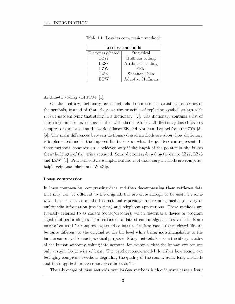
Table 1.1: Lossless compression methods
Lossless methodsDictionary-based Statistical
LZ77 Huffman codingLZSS Arithmetic codingLZW PPMLZS Shannon-Fano
BTW Adaptive Huffman
Arithmetic coding and PPM [1].On the contrary, dictionary-based methods do not use the statistical properties of
the symbols, instead of that, they use the principle of replacing symbol strings withcodewords identifying that string in a dictionary [2]. The dictionary contains a list ofsubstrings and codewords associated with them. Almost all dictionary-based losslesscompressors are based on the work of Jacov Ziv and Abraham Lempel from the 70’s [5],[6]. The main differences between dictionary-based methods are about how dictionaryis implemented and in the imposed limitations on what the pointers can represent. Inthese methods, compression is achieved only if the length of the pointer in bits is lessthan the length of the string replaced. Some dictionary-based methods are LZ77, LZ78and LZW [1]. Practical software implementations of dictionary methods are compress,bzip2, gzip, zoo, pkzip and WinZip.
Lossy compression
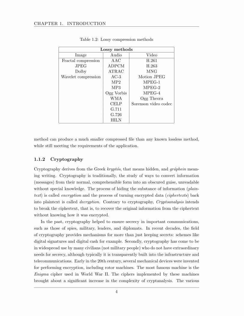
In lossy compression, compressing data and then decompressing them retrieves datathat may well be different to the original, but are close enough to be useful in someway. It is used a lot on the Internet and especially in streaming media (delivery ofmultimedia information just in time) and telephony applications. These methods aretypically referred to as codecs (coder/decoder), which describes a device or programcapable of performing transformations on a data stream or signals. Lossy methods aremore often used for compressing sound or images. In these cases, the retrieved file canbe quite different to the original at the bit level while being indistinguishable to thehuman ear or eye for most practical purposes. Many methods focus on the idiosyncrasiesof the human anatomy, taking into account, for example, that the human eye can seeonly certain frequencies of light. The psychoacoustic model describes how sound canbe highly compressed without degrading the quality of the sound. Some lossy methodsand their application are summarized in table 1.2.
The advantage of lossy methods over lossless methods is that in some cases a lossy
3
CHAPTER 1. INTRODUCTION
Table 1.2: Lossy compression methods
Lossy methodsImage Audio Video
Fractal compression AAC H.261JPEG ADPCM H.263Dolby ATRAC MNG
Wavelet compression AC-3 Motion JPEGMP2 MPEG-1MP3 MPEG-2
Ogg Vorbis MPEG-4WMA Ogg TheoraCELP Sorenson video codecG.711G.726HILN
method can produce a much smaller compressed file than any known lossless method,while still meeting the requirements of the application.
1.1.2 Cryptography
Cryptography derives from the Greek kryptos, that means hidden, and graphein mean-ing writing. Cryptography is traditionally, the study of ways to convert information(messages) from their normal, comprehensible form into an obscured guise, unreadablewithout special knowledge. The process of hiding the substance of information (plain-text) is called encryption and the process of turning encrypted data (ciphertexts) backinto plaintext is called decryption. Contrary to cryptography, Cryptoanalysis intendsto break the ciphertext, that is, to recover the original information from the ciphertextwithout knowing how it was encrypted.
In the past, cryptography helped to ensure secrecy in important communications,such as those of spies, military, leaders, and diplomats. In recent decades, the fieldof cryptography provides mechanisms for more than just keeping secrets: schemes likedigital signatures and digital cash for example. Secondly, cryptography has come to bein widespread use by many civilians (not military people) who do not have extraordinaryneeds for secrecy, although typically it is transparently built into the infrastructure andtelecommunications. Early in the 20th century, several mechanical devices were inventedfor performing encryption, including rotor machines. The most famous machine is theEnigma cipher used in World War II. The ciphers implemented by these machinesbrought about a significant increase in the complexity of cryptanalysis. The various
4
1.1. INTRODUCTION
attacks on Enigma, for example, succeeded only after considerable effort. With theadvent of digital computers and electronics, very complex ciphers could be implemented.A characteristic of computer ciphers is that they operate on binary strings, unlikeclassical and mechanical schemes which use an alphabet of about 26 letters, dependingon the language.
Cryptography is an interdisciplinary subject, drawing from several fields. Before thetime of computers, it was closely related to linguistics. Nowadays, cryptography makesextensive use of technical areas of mathematics, notably number theory, informationtheory, computational complexity, statistics and finite (discrete) mathematics.
Cryptography is commonly used for securing communications. Four properties aredesirable and cryptography provides them, they are:
• Confidentiality. The information access is limited only to authorized entities.
• Authentication. Ensures that parties involved in a transaction are who they saythey are. Also it lets to establish the origin of data.
• Integrity. Information is protected from alterations when it is transmitted. Dataalterations can be deletion, insertion and substitution.
• Non-repudiation. It prevents an entity deny it had been involved in a previousaction.
A cryptographic algorithm, also called a cipher, is one that provides one of the prop-erties or services listed above. This algorithm is called restricted if it bases its securityon keeping the way of working in secret. This kind of algorithms are rarely used today,they are popularly used only for low-security applications. Modern cryptographic algo-rithms base its security on the use of a key. The encryption and decryption functions,denoted as E and D respectively, use and depend on that key.
Similar to the compression methods, cryptography is classified in two groups, sym-metric and asymmetric cryptography [3]. This classification is according to how theyuse the key for performing the cryptographic operations.
Symmetrical algorithms
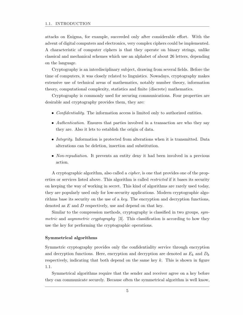
Symmetric cryptography provides only the confidentiality service through encryptionand decryption functions. Here, encryption and decryption are denoted as Ek and Dk
respectively, indicating that both depend on the same key k. This is shown in figure1.1.
Symmetrical algorithms require that the sender and receiver agree on a key beforethey can communicate securely. Because often the symmetrical algorithm is well know,
5
CHAPTER 1. INTRODUCTION
Message
Encryption operation
encrypted message
Received encrypted Message
Decryption operation
Private key
Symmetrical data encryption
Symmetrical data decryption
decrypted message Private key
Figure 1.1: Symmetrical cryptography
Message
Encryption operation
Public key encrypted message
Received encrypted Message
Decryption operation
Private key
Public key data encryption
Public key data decryption
decrypted message
Figure 1.2: Asymmetrical cryptography
the security rests on the key. This key must be kept secret as long as the communicationneeds to remind secret. Symmetrical algorithms can be divided into two categories:block ciphers and stream ciphers. The first ones operate on plaintext one bit or byte ata time. The second ones operate in groups of bits or bytes, a typical block size used is64 bits. Examples of symmetrical algorithms are AES, FEAL, IDEA, DES, and 3DES[3].
Asymmetrical or public-key algorithms
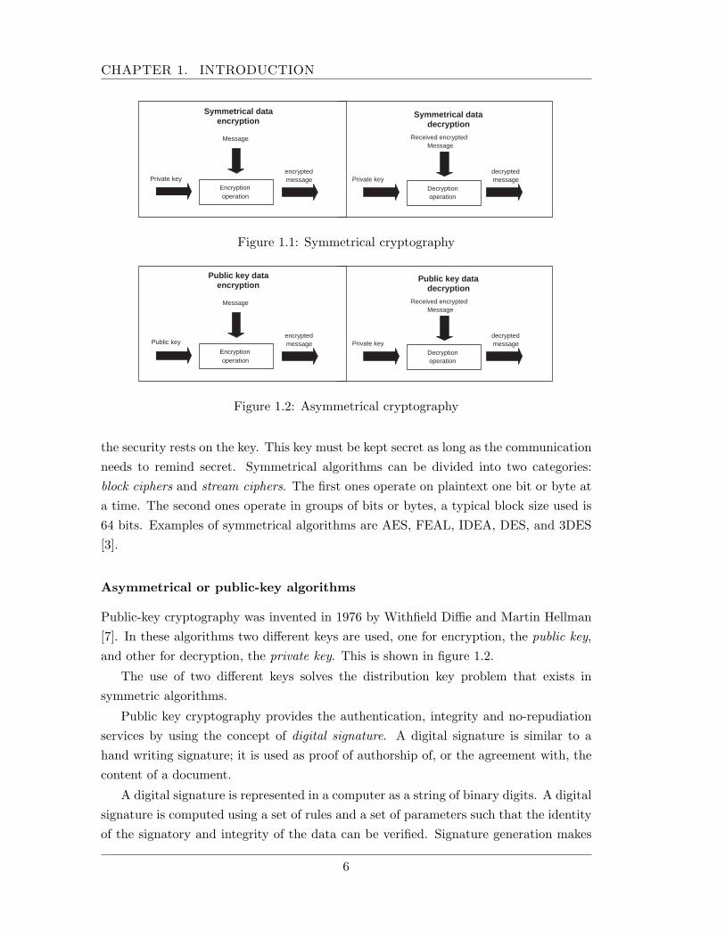
Public-key cryptography was invented in 1976 by Withfield Diffie and Martin Hellman[7]. In these algorithms two different keys are used, one for encryption, the public key,and other for decryption, the private key. This is shown in figure 1.2.
The use of two different keys solves the distribution key problem that exists insymmetric algorithms.
Public key cryptography provides the authentication, integrity and no-repudiationservices by using the concept of digital signature. A digital signature is similar to ahand writing signature; it is used as proof of authorship of, or the agreement with, thecontent of a document.
A digital signature is represented in a computer as a string of binary digits. A digitalsignature is computed using a set of rules and a set of parameters such that the identityof the signatory and integrity of the data can be verified. Signature generation makes
6

1.1. INTRODUCTION
Message
HASH Function
Message digest
SIGN operation
Private key Digital Signature
Received Message
HASH Function
Message digest
Verify operation
Public key Digital Signature
YES - Signature verified NO - Signature verification failed
Signature generation Signature verification
Figure 1.3: Digital signature
use of a private key to generate a digital signature. Signature verification makes use ofa public key which corresponds to, but is not the same as, the private key. Each userpossesses a private and public key pair. Public keys are assumed to be known to thepublic in general. Private keys are never shared. Anyone can verify the signature of auser by employing that user’s public key. Signature generation can be performed onlyby the possessor of the user’s private key.
Figure 1.3 shows the signature generation and verification operations. A hashfunction [3] is used in the signature generation process to obtain a condensed version ofdata, called a message digest. The message digest is then input to the digital signaturealgorithm to generate the digital signature. The digital signature is sent to the intendedverifier along with the signed data (often called the message). The verifier of the messageand signature verifies the signature by using the sender’s public key. The same hashfunction must also be used in the verification process.
A hash function H is a transformation that takes a variable-size input m and returnsa fixed-size bit string, which is called the hash value h ( h = H(m)). Hash functionshave a variety of general computational uses but when employed in cryptography, thehash functions need to have the following properties [3]:
1. H(m) is relatively easy to compute for any given message m.
2. H(m) is one-way.
3. H(m) is collision-free.
7
CHAPTER 1. INTRODUCTION
A hash function H is said to be one-way if given a hash value h, it is computationallyinfeasible to find some input m such that H(m) = h. If a message m1 is given, it is com-putationally infeasible to find a message m2 different to m1, such that H(m1) = H(m2),then H is said to be a collision-free hash function. A hash function enables the determi-nation of a message’s integrity: any change to the message will result, with a very highprobability, in a different message digest. This property is used in the generation andverification of digital signatures and message authentication code algorithms. Examplesof hash functions are MD2, MD5 and SHA-1 [4].
A MAC algorithm is intended for determining if data have been modified whentransmitted over a computer network. For example, in a text the word do may havebeen changed to do not or $1,000 may have been changed to $ 3,000. Without additionalinformation, a human could easily accept the altered data as being authentic. Thesethreats may still exist even when data encryption is used. It is therefore desirable to havean automated mechanism for detecting both intentional and unintentional modificationsto data. A cryptographic Data Authentication Algorithm (DAA) can protect againstboth accidental and intentional, but unauthorized, data modification.
MAC stands for Message Authentication Code. In general, a MAC can be thoughtof as a checksum for data passed through an unreliable (or more importantly, unsecure)pipeline. A sender will typically generate a MAC code by first passing their message intosome MAC algorithm. The sender will then send their message D with the MAC(D)value. The receiver can then generate their own MAC1(D) and verify if the sent MACvalue matches the currently computed one. A MAC algorithm can be generated usingmultiple different techniques; however, sender and receiver generally need to have ashared secret key, kMAC .
A hash function alone cannot act as a MAC function. An attacker could interceptthe message D and Hash(D). He could then resend as D′ and Hash(D′). The receivercould then not tell that the message had been altered. In other words, Hash functionscan help prevent error in an unreliable channel, but not in an insecure channel.
Although public key cryptography was proposed in 1976, the first cryptosystemappeared in 1978, it was the RSA cryptosystem. This is the most accepted public-keycryptosystem and used in all over the world. Other cryptosystems are Diffie-Hellman[7], ElGamal, DSA, Rabin [4] and ECC [8]. Elliptic curve cryptography is a type ofpublic-key algorithm based on the mathematics of elliptic curves (defined by certaincubic equations). It has been claimed that ECC can be faster and use shorter keys thanother public-key algorithms available while providing an equivalent level of security.Using short keys implies lower storage requirements and faster arithmetic computations.This is specially important when implementing public-key cryptography on constrainedenvironments, like in mobile and wireless devices.
8
1.2. PLATFORMS FOR ALGORITHM IMPLEMENTATION
The security of public-key algorithms is usually based on hard mathematical prob-lems. Just three conjectured hard problems have been cosidered in public-key crypto-graphic schemes: big integer factorization, computation of discrete logarithms and thecomputation of discrete logarithms in elliptic curves. Because computations in public-key algorithms are more complex than in symmetrical ones, for efficiency reasons, hybridencryption systems are used in practice; a key is exchanged using a public-key cipher,and the rest of the communication is encrypted using symmetrical encryption, which istypically much faster.
The security of all practical encryption schemes remains unproven, both for sym-metric and asymmetric ones. For symmetric ciphers, confidence gained in an algorithmis usually anecdotal, no successful attack has been reported on an algorithm for severalyears despite intensive analysis. For asymmetric schemes, it is common to rely on thedifficulty of the associated mathematical problem, but this, is not provably secure.
Extensive academic research into modern cryptography is relatively recent, it beganin the open community during the 1970s with the specification of DES and the inventionof RSA algorithms. Popular applications such as the Internet and mobile phones haverepositioned cryptography.
1.2 Platforms for algorithm implementation
There are two primary methods in conventional computing for the execution of algo-rithms [9]. The first one is to use hardwired technology, either an Application SpecificIntegrated Circuit (ASIC) or a group of individual components forming a board-levelsolution, to perform the operations in hardware. ASICs are designed specifically toperform a given computation, and thus they are very fast and efficient when executingthe exact computation for which they were designed. However, the circuit cannot bealtered after fabrication. This forces a redesign and refabrication of the chip if anypart of its circuit requires modification. This is an expensive process, especially whenone considers the difficulties of replacing ASICs in a large number of deployed systems.Board-level circuits are also somewhat inflexible, frequently requiring a board redesignand replacement in the event of changes to the application.
The second method is to use software-programmed microprocessors, a far moreflexible solution. Processors execute a set of instructions to perform a computation. Bychanging the software instructions, the functionality of the system is altered withoutchanging the hardware. However, the downside of this flexibility is that the performancecan suffer, if not in clock speed then in work rate, and is far below that of an ASIC.The processor must read each instruction from memory, decode its meaning, and onlythen execute it. This results in a high execution overhead for each individual operation.
9
CHAPTER 1. INTRODUCTION
Additionally, the set of instructions that may be used by a program is determined atthe processor fabrication time. Any other operations that are to be implemented mustbe built out of existing instructions.
Reconfigurable computing is intended to fill the gap between hardware and soft-ware, achieving potentially much higher performance than software, while maintain-ing a higher level of flexibility than hardware. Reconfigurable devices, including field-programmable gate arrays (FPGAs), contain an array of computational elements whosefunctionality is determined through multiple programmable configuration bits. Theseelements, sometimes known as logic blocks, are connected using a set of routing re-sources that are also programmable. In this way, custom digital circuits can be mappedto the reconfigurable hardware by computing the logic functions of the circuit withinthe logic blocks, and using the configurable routing to connect the blocks together toform the necessary circuit.
Compression and cryptographic algorithms are expensive in terms of time whenthey are implemented in general purpose processors. When implementing compressionalgorithms, the search for redundancy implies a lot of complex operations that can not beimplemented efficiently with the available instruction set of a general purpose processor.And when cryptographic algorithms are implemented, it is necessary to perform a highamount of mathematical operations between large numbers in a finite field. Again,general purpose processors do not have instructions to support these operations leadingto inefficient implementations. For these reasons, a hardware solution is well suited toimplement both kinds of algorithms, especially for real time data processing.
FPGAs and reconfigurable computing have shown to accelerate a variety of ap-plications. Recent applications that have shown to exhibit significant speedups usingreconfigurable hardware include: automatic target recognition, string pattern matching,transitive closure of dynamic graphs, data compression, and genetic algorithms for thetraveling salesman problem. Specifically, in cryptographic applications, there are manycriteria which lead to prefer programmable devices instead of an ASIC option [10],these are:
• Algorithm Agility: Switching of cryptographic algorithms during operation ofthe targeted application. Whereas algorithm agility is costly with traditionalhardware, FPGAs can be reprogrammed on the fly.
• Algorithm Upload: Devices are upgraded with a new encryption algorithmbecause of different reasons, for example, algorithm was broken or a new standardwas created.
• Architecture Efficiency: A hardware architecture can be much more efficient
10
1.2. PLATFORMS FOR ALGORITHM IMPLEMENTATION
if it is designed for an specific set of parameters, for example the key or theunderlying finite field. The more specific an algorithm is implemented the moreefficient it can become. FPGAs allow this type of design and optimization withan specific parameter set. Due to the nature of FPGAs, the application can bechanged totally or partially.
• Resource Efficiency: The majority of security protocols, like IPSec and SSL,are hybrid protocols. Since the algorithms are not used simultaneously, the sameFPGA device can be used for both through runtime reconfiguration.
• Throughput: General-purpose processors are not optimized for fast executionespecially in the case of public-key algorithms. This is because they do not have in-structions for modular arithmetic operations on long operands, which is necessaryin those kinds of algorithms. Although typically slower than ASIC implementa-tions, FPGA implementations have the potential of running substantially fasterthan software implementations.
The advantages of software implementations include easy of use, ease of upgrade,portability, low development costs and low unit prices and flexibility; a software imple-mentation offers moderate speed, high power consumption compared to custom hard-ware, and only limited physical security, especially with respect to key storage. ASICimplementations show lower price per unit, can reach high speeds, and can have lowpower dissipation. Hardware implementations of cryptographic algorithms are more se-cure because they cannot be easily read or modified by an outside attacker as softwareimplementations. The lack of flexibility of ASIC implementations with respect to thealgorithms and parameter, leads to higher development costs and switching. Althoughreconfigurable hardware devices, such as FPGAs, seem to combine the advantages ofsoftware and hardware implementations, there are still many open questions regardingFPGAs as a module for security functions [10].
1.2.1 Field programmable gate array (FPGA)
Field programmable gate arrays are specific integrated circuits that can be programmedeasily. The FPGA contains versatile functions, configurable interconnects and an in-put/output interface to adapt to the user specification. FPGAs allow rapid prototypingusing custom logic structures, and are very popular for limited device production. Mod-ern FPGA are extremely dense, with a complexity of several millions of gates which en-able the emulation of very complex hardware such as parallel microprocessors, mixtureof processor and signal processing. One key advantage of FPGAs is the possibility ofreprogramming them, in order to create a completely different hardware by modifying
11
CHAPTER 1. INTRODUCTION
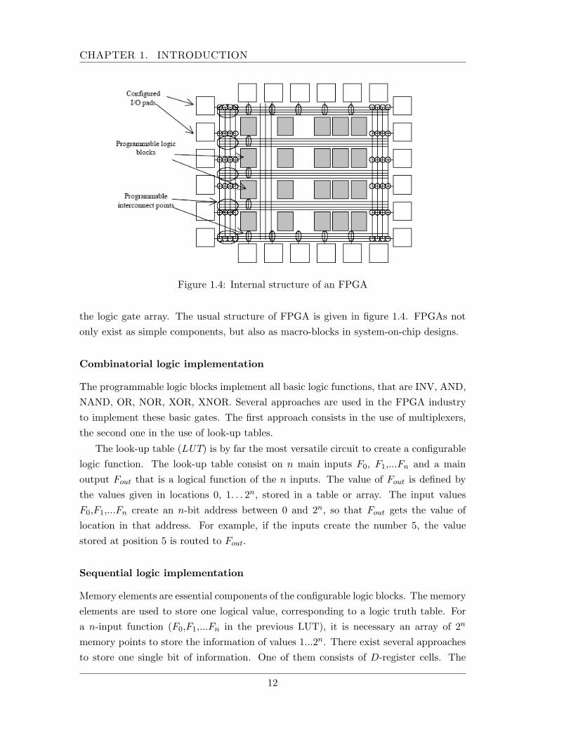
Figure 1.4: Internal structure of an FPGA
the logic gate array. The usual structure of FPGA is given in figure 1.4. FPGAs notonly exist as simple components, but also as macro-blocks in system-on-chip designs.
Combinatorial logic implementation
The programmable logic blocks implement all basic logic functions, that are INV, AND,NAND, OR, NOR, XOR, XNOR. Several approaches are used in the FPGA industryto implement these basic gates. The first approach consists in the use of multiplexers,the second one in the use of look-up tables.
The look-up table (LUT) is by far the most versatile circuit to create a configurablelogic function. The look-up table consist on n main inputs F0, F1,...Fn and a mainoutput Fout that is a logical function of the n inputs. The value of Fout is defined bythe values given in locations 0, 1. . . 2n, stored in a table or array. The input valuesF0,F1,...Fn create an n-bit address between 0 and 2n, so that Fout gets the value oflocation in that address. For example, if the inputs create the number 5, the valuestored at position 5 is routed to Fout.
Sequential logic implementation
Memory elements are essential components of the configurable logic blocks. The memoryelements are used to store one logical value, corresponding to a logic truth table. Fora n-input function (F0,F1,...Fn in the previous LUT), it is necessary an array of 2n
memory points to store the information of values 1...2n. There exist several approachesto store one single bit of information. One of them consists of D-register cells. The
12
1.3. DESCRIPTION OF THE PROBLEM
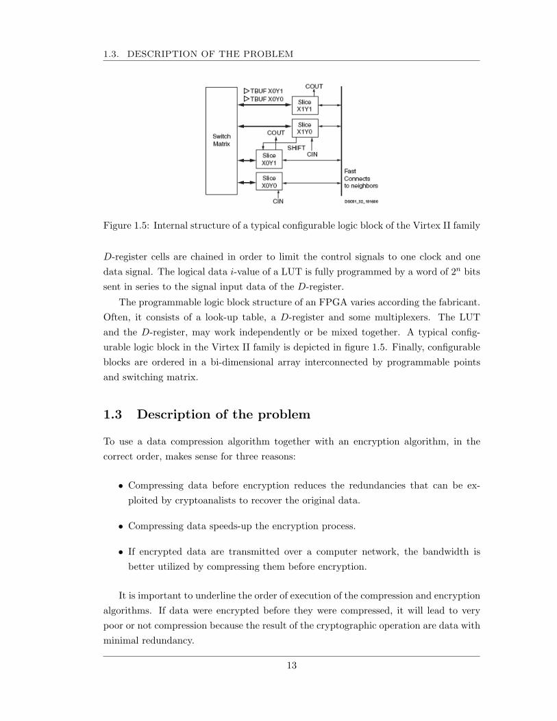
Figure 1.5: Internal structure of a typical configurable logic block of the Virtex II family
D-register cells are chained in order to limit the control signals to one clock and onedata signal. The logical data i-value of a LUT is fully programmed by a word of 2n bitssent in series to the signal input data of the D-register.
The programmable logic block structure of an FPGA varies according the fabricant.Often, it consists of a look-up table, a D-register and some multiplexers. The LUTand the D-register, may work independently or be mixed together. A typical config-urable logic block in the Virtex II family is depicted in figure 1.5. Finally, configurableblocks are ordered in a bi-dimensional array interconnected by programmable pointsand switching matrix.
1.3 Description of the problem
To use a data compression algorithm together with an encryption algorithm, in thecorrect order, makes sense for three reasons:
• Compressing data before encryption reduces the redundancies that can be ex-ploited by cryptoanalists to recover the original data.
• Compressing data speeds-up the encryption process.
• If encrypted data are transmitted over a computer network, the bandwidth isbetter utilized by compressing them before encryption.
It is important to underline the order of execution of the compression and encryptionalgorithms. If data were encrypted before they were compressed, it will lead to verypoor or not compression because the result of the cryptographic operation are data withminimal redundancy.
13
CHAPTER 1. INTRODUCTION
The approach of combining compression with cryptography has been adopted insome software applications like HiFn [11], PKWare [12], PGP [3] and CyberFUSION[13]. Also, some network security protocols like SSL, SSH and IPSec compress databefore encryption as part of the transferring process.
PGP (Pretty Good Privacy) provides the confidence and authentication servicesfor sending e-mail and information storage. RSA is used for public key cryptographyand CAST-128, IDEA y 3DES for symmetric encryption. The message to be sentis compressed, either after if it is signed or before if it is encrypted, using the ZIPalgorithm. The 6.0 version of the compression program PKZip can encrypt data forstorage or transfer. The 256-bit key AES algorithm is used for symmetric encryptionand RSA for asymmetical one. In CyberFUSION, similar to an FPT application, dataare encrypted using either the DES or 3DES algorithm. Compression is performed usingthe RLE (Run Length Encoding) algorithm.
HiFn has proposed a processor to perform both compression and encryption oper-ations. Cryptographic algorithms supported by this processor are AES and 3DES forsymmetrical encryption and SHA-1 and MD5 for authentication [3]; compression isperformed by the LZS (Lempel-Ziv-Stac) [14] algorithm. CISCO offers some hardwareand software modules to encrypt and compresses data that can be incorporated intorouters in order to improve the performance of data transmission. Data can be com-pressed by the LZS algorithm or by the IPPCP compression protocol; the compresseddata are encrypted by the AES algorithm with a 128, 192 or 256-bit key.
Although some effort has been done by some enterprises for combining compressionand cryptography, asymmetrical encryption has not been considered. In addition, justsoftware implementations have been considered. And as mentioned before, compressionand cryptographic algorithms are expensive in terms of time when they are implementedin general purpose processors. When implementing compression algorithms, the searchfor redundancy implies a lot of complex operations that can not be implemented ef-ficiently with the available instruction set of a general purpose processor. And whencryptographic algorithms are implemented, it is necessary to perform a high amount ofmathematical operations with large numbers in a finite field. Again, general purposeprocessors do not have instructions to support these operations leading to inefficientimplementations. For these reasons, a hardware solution is well suited to implementboth kinds of algorithms, especially for real time data processing.
In this research work, a hardware architecture, combining lossless compression andasymmetric encryption is presented. The system architecture consists of a dictionary-based lossless data compressor that compresses the incoming data, and an elliptic curvecryptographic module that performs two EC (elliptic curve) cryptographic schemes:encryption and digital signature. The lossless compressor was selected because of its
14
1.4. MOTIVATION
relatively low requirements in area and average compression ratio. This kind of com-pressors performs well in universal data and it is faster to compress if compared withother lossless compressors. The asymmetrical cryptosystem ECC was selected becauseof the advantages it presents with respect to other public-key schemes: it uses shorterlength keys while providing the same security level. The use of shorter keys implies lessspace for key storage and saving of time when the keys are transmitted. Also, arithmeticoperations are computed faster when operands are reduce in size. ECC bases its securityon a harder mathematical problem which makes it be more secure than traditionallyschemes, for example RSA.
1.4 Motivation
The combination of two of the most important technologies in network applications,compression and encryption, has not been exploited extensively. Elliptic Curve Cryp-tography (ECC) is a novel approach that is beginning to be used in practical applicationsas an alternative to RSA, the most widely used public key cryptosystem. ECC offersthe same security level than RSA using shorter length keys, up to six times. This factleads to require less storage memory for keys and improves the execution of the arith-metic operations. These characteristics of ECC make it attractive to be implementedin constrained devices, for example, in wireless devices.
The main motivation to implement the complete system in hardware is the potentialfor higher execution speed. In both, compression and encryption, a lot of complexoperations are required, so they run inefficiently in general purpose processors that donot count with specialized instructions to support that kind of operations. The speed-up is obtained by designing custom architectures executing the most time consumingparts in each of the algorithms.
Although it seems to be a high and complex system joining two algorithms, with theavailable technology, FPGAs and high level hardware description languages, it seemsto be possible the realization of such system in a relative short period of time. Thatis what this work intends to achieve in order to demostrate the premisses given in theprevious section. Encrypting compressed data gathers the advantages of compressionand encryption: data is transmitted in a secure way reducing space and time costs forstorage, and the time to encrypt data.
15
CHAPTER 1. INTRODUCTION
1.5 Thesis objectives
1.5.1 General objective
The general objective of this research work is to demonstrate the theoretical advantagesof combining lossless data compression and public key cryptography. To achieve thisobjective, a hardware architecture for dictionary-based data compression and ellipticcurve cryptography that meets real time requirements is implemented. Unlike tradi-tional approaches, this work considers public-key cryptography instead of symmetricalone.
1.5.2 Specific Objectives
Specific objective is to validate the performance of elliptic curve cryptography by addingdata compression. On this specific objective, it is desired to prove the following state-ments:
1. Compression can improve the performance in the cryptographic module, how oc-curs in symmetrical methods.
2. The available bandwidth is better utilized when encrypted data are transmitted.
3. It is possible to combine two different algorithms in a single hardware architecture.
1.6 Methodology
To meet real time requirements, the design and implementation of the system is carriedout by applying parallelism at algorithmic level. Although parallelism at the level ofdesign can be applied, it was decided not to apply it or minimally. That is because it ispreferable a generic architecture that can be implemented in any programmable device.When such device is selected, optimizations for that device can be done. However, withcurrent sophisticated synthesis tools, such optimizations often are transparent to theuser.
The searching for redundancy in data compression is implemented using a systolicarray approach. Systolic arrays achieve high clock rates while using low area resourcesand provide better testability. In the cipher, the arithmetic operations are implementedas parallel as possible, identifying data dependences and utilizing custom datapaths andspecialized architectures.
For validating the hardware system, a software version of the proposed system wasdeveloped for results comparison and test benches generation. Both, the compressor
16
1.7. OVERVIEW OF THE THESIS
Design Entry
Design Synthesis
Design Implementation
Download to a FPGA device
Design verification
Functional simulation
Static timing simulation
Timing simulation
In-circuit verification
Back Annotation
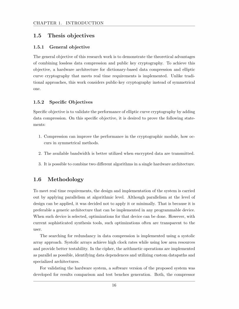
Figure 1.6: Flow design of the system
and the ECC cipher are written in C, letting to migrate the code to any platforms withvery few or no changes at all.
The hardware architecture is described in the standard hardware description lan-guage VHDL, making possible any rapid further modification. Hardware modules aredescribed as parameterelizable as possible, leading to a scalable implementation. Thehardware architecture was simulated on Active-HDL software and synthesized for theVirtex II FPGAS family using ISE software. The design flow of the system was carriedout following the flow design of an FPGA system, shown in figure 1.6.
1.7 Overview of the thesis
The thesis is organized as follows: The next chapter presents the background for thelossless data compressor and the mathematical background and cryptographic schemesfor elliptic curve cryptography. Chapter 3 presents the architecture design of the systemexplainig its internal modules in detail. Chapter 4 shows the synthesis results and aresults comparison against reported work. Finally, Chapter 5 summarizes this work andthe contributions of this thesis. Conclusions and directions are presented at the end ofChapter 5.
17
CHAPTER 1. INTRODUCTION
18
Chapter 2
LZ compression and Elliptic
Curve Cryptography
In this chapter, a discussion about the selection of the data compression algorithm,a variant of the original LZ77 algorithm, is presented. Also, this chapter provides themathematical background of elliptic curve cryptography and additional algorithms usedin the elliptic curve cryptographic schemes treated in this work.
2.1 The data compression module
The main system is focused to encryption of text, so lossless compression is selected asa compressor module in the system. In all lossless compression implementations, thereis a trade-off between computational resources and compression ratio. Often, in bothstatistical and dictionary-based methods, the best compression ratios are obtained atexpenses of long execution time, high memory and logic gates. Statistical compressorsare characterized for consuming higher resources than dictionary based when they areimplemented in both software and hardware, however they can achieve compressionratios near to the source entropy. The most demanding task in this kind of algorithmsis the implementation of the model to get the statistics of the symbols and to assignthe bit string. Perhaps, the most representative statistical method is the proposed byDavid Huffman [15] in 1952. In this algorithm a tree is built according to the frequencyof the symbols. All symbols are placed at the leaves of the tree. The Huffman methodachieves compression by replacing every symbol by a variable bit string. The bit stringassigned to every symbol is determined by visiting every internal node from the root upto the leaf corresponding to the symbol. Initially the bit string is the null string. Forevery internal node visited, one bit is concatenated to the bit string, 1 or 0, dependingon the current visited node whether it is a right or left child of its father. Symbols at
19
CHAPTER 2. LZ COMPRESSION AND ELLIPTIC CURVECRYPTOGRAPHY
0
0,1
0,2
0,3
0,4
0,5
0,6
0,7
0,8
0,9
Huffman RLE LZW LZSS
Compression ratio
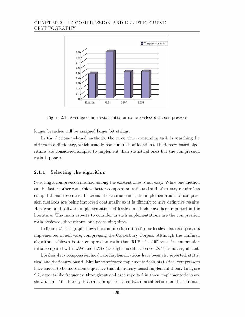
Figure 2.1: Average compression ratio for some lossless data compressors
longer branches will be assigned larger bit strings.
In the dictionary-based methods, the most time consuming task is searching forstrings in a dictionary, which usually has hundreds of locations. Dictionary-based algo-rithms are considered simpler to implement than statistical ones but the compressionratio is poorer.
2.1.1 Selecting the algorithm
Selecting a compression method among the existent ones is not easy. While one methodcan be faster, other can achieve better compression ratio and still other may require lesscomputational resources. In terms of execution time, the implementations of compres-sion methods are being improved continually so it is difficult to give definitive results.Hardware and software implementations of lossless methods have been reported in theliterature. The main aspects to consider in such implementations are the compressionratio achieved, throughput, and processing time.
In figure 2.1, the graph shows the compression ratio of some lossless data compressorsimplemented in software, compressing the Canterbury Corpus. Although the Huffmanalgorithm achieves better compression ratio than RLE, the difference in compressionratio compared with LZW and LZSS (as slight modification of LZ77) is not significant.
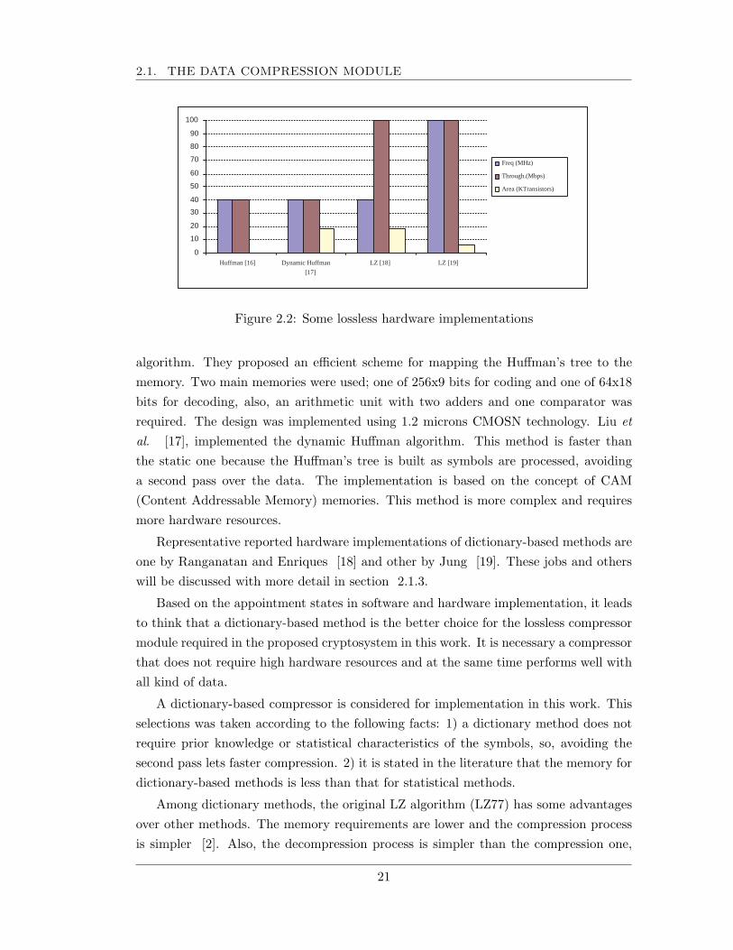
Lossless data compression hardware implementations have been also reported, statis-tical and dictionary based. Similar to software implementations, statistical compressorshave shown to be more area expensive than dictionary-based implementations. In figure2.2, aspects like frequency, throughput and area reported in those implementations areshown. In [16], Park y Prassana proposed a hardware architecture for the Huffman
20
2.1. THE DATA COMPRESSION MODULE
0
10
20
30
40
50
60
70
80
90
100
Huffman [16] Dynamic Huffman
[17]
LZ [18] LZ [19]
Freq (MHz)
Through.(Mbps)
Area (KTransistors)
Figure 2.2: Some lossless hardware implementations
algorithm. They proposed an efficient scheme for mapping the Huffman’s tree to thememory. Two main memories were used; one of 256x9 bits for coding and one of 64x18bits for decoding, also, an arithmetic unit with two adders and one comparator wasrequired. The design was implemented using 1.2 microns CMOSN technology. Liu etal. [17], implemented the dynamic Huffman algorithm. This method is faster thanthe static one because the Huffman’s tree is built as symbols are processed, avoidinga second pass over the data. The implementation is based on the concept of CAM(Content Addressable Memory) memories. This method is more complex and requiresmore hardware resources.
Representative reported hardware implementations of dictionary-based methods areone by Ranganatan and Enriques [18] and other by Jung [19]. These jobs and otherswill be discussed with more detail in section 2.1.3.
Based on the appointment states in software and hardware implementation, it leadsto think that a dictionary-based method is the better choice for the lossless compressormodule required in the proposed cryptosystem in this work. It is necessary a compressorthat does not require high hardware resources and at the same time performs well withall kind of data.
A dictionary-based compressor is considered for implementation in this work. Thisselections was taken according to the following facts: 1) a dictionary method does notrequire prior knowledge or statistical characteristics of the symbols, so, avoiding thesecond pass lets faster compression. 2) it is stated in the literature that the memory fordictionary-based methods is less than that for statistical methods.
Among dictionary methods, the original LZ algorithm (LZ77) has some advantagesover other methods. The memory requirements are lower and the compression processis simpler [2]. Also, the decompression process is simpler than the compression one,
21
CHAPTER 2. LZ COMPRESSION AND ELLIPTIC CURVECRYPTOGRAPHY
Symbols discarded
Incoming symbols
Searching buffer X
Coding buffer Y
k a a a ... 2 1 ... 2 1 k k a a n k a ... 2 1 n k n k a a m n k a ... 2 1 m n k m n k
a a
Size N Symbols processed Current dictionary
Size M Symbols to be
processed
+ + + + + + + + + + + + + + +
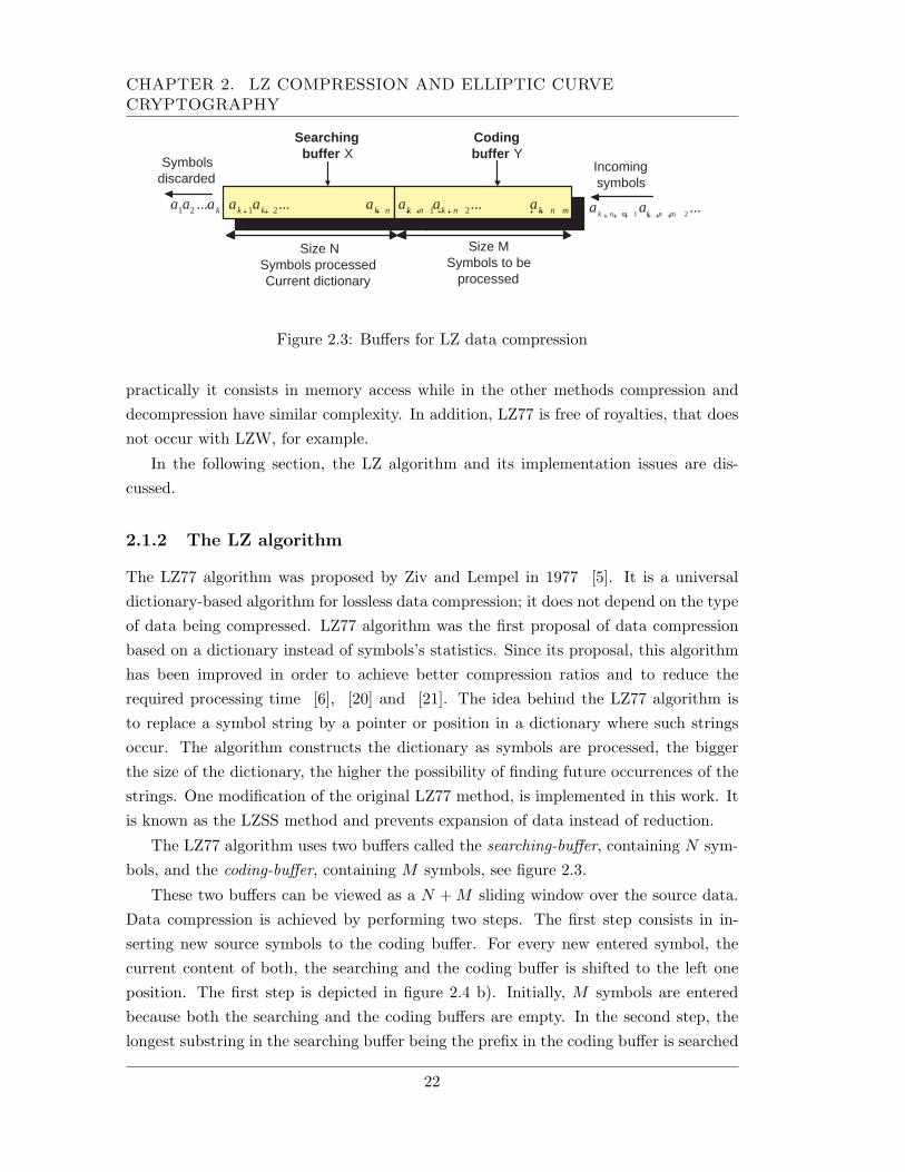
Figure 2.3: Buffers for LZ data compression
practically it consists in memory access while in the other methods compression anddecompression have similar complexity. In addition, LZ77 is free of royalties, that doesnot occur with LZW, for example.
In the following section, the LZ algorithm and its implementation issues are dis-cussed.
2.1.2 The LZ algorithm
The LZ77 algorithm was proposed by Ziv and Lempel in 1977 [5]. It is a universaldictionary-based algorithm for lossless data compression; it does not depend on the typeof data being compressed. LZ77 algorithm was the first proposal of data compressionbased on a dictionary instead of symbols’s statistics. Since its proposal, this algorithmhas been improved in order to achieve better compression ratios and to reduce therequired processing time [6], [20] and [21]. The idea behind the LZ77 algorithm isto replace a symbol string by a pointer or position in a dictionary where such stringsoccur. The algorithm constructs the dictionary as symbols are processed, the biggerthe size of the dictionary, the higher the possibility of finding future occurrences of thestrings. One modification of the original LZ77 method, is implemented in this work. Itis known as the LZSS method and prevents expansion of data instead of reduction.
The LZ77 algorithm uses two buffers called the searching-buffer, containing N sym-bols, and the coding-buffer, containing M symbols, see figure 2.3.
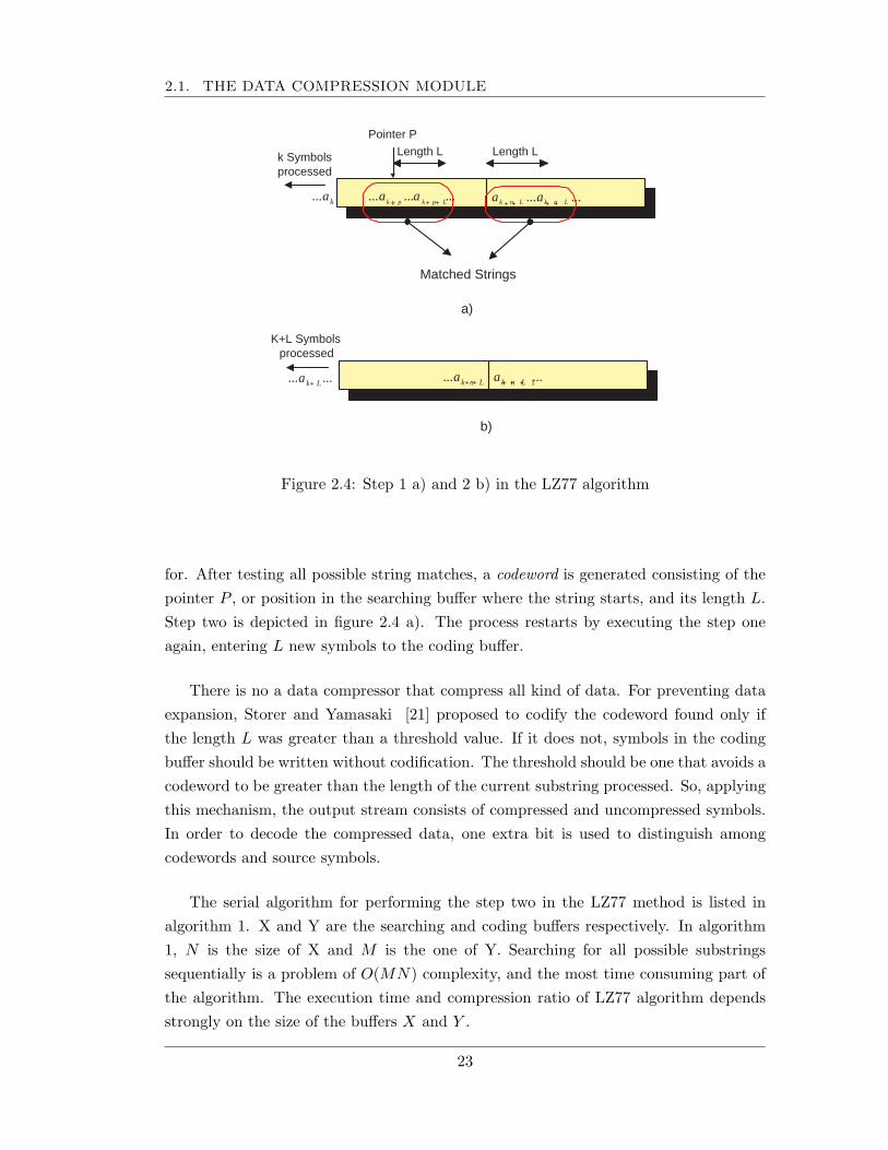
These two buffers can be viewed as a N + M sliding window over the source data.Data compression is achieved by performing two steps. The first step consists in in-serting new source symbols to the coding buffer. For every new entered symbol, thecurrent content of both, the searching and the coding buffer is shifted to the left oneposition. The first step is depicted in figure 2.4 b). Initially, M symbols are enteredbecause both the searching and the coding buffers are empty. In the second step, thelongest substring in the searching buffer being the prefix in the coding buffer is searched
22
2.1. THE DATA COMPRESSION MODULE
k Symbols processed
k a ... ... ... ... L p k p k
a a ... ... L n k L n k a a
Matched Strings
Pointer P
Length L Length L
a)
K+L Symbols processed
... ... L k a L n k a ... ... 1 L n k a
b)
+ + + + + + +
+ + + + + +
Figure 2.4: Step 1 a) and 2 b) in the LZ77 algorithm
for. After testing all possible string matches, a codeword is generated consisting of thepointer P , or position in the searching buffer where the string starts, and its length L.Step two is depicted in figure 2.4 a). The process restarts by executing the step oneagain, entering L new symbols to the coding buffer.
There is no a data compressor that compress all kind of data. For preventing dataexpansion, Storer and Yamasaki [21] proposed to codify the codeword found only ifthe length L was greater than a threshold value. If it does not, symbols in the codingbuffer should be written without codification. The threshold should be one that avoids acodeword to be greater than the length of the current substring processed. So, applyingthis mechanism, the output stream consists of compressed and uncompressed symbols.In order to decode the compressed data, one extra bit is used to distinguish amongcodewords and source symbols.
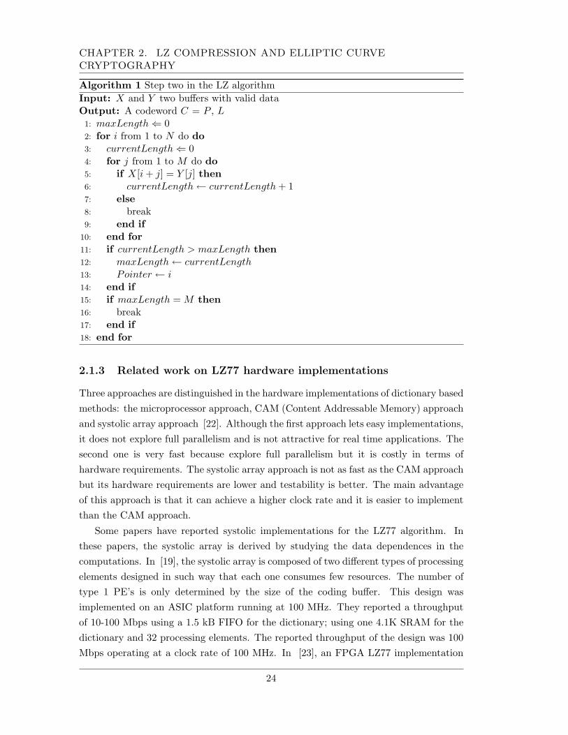
The serial algorithm for performing the step two in the LZ77 method is listed inalgorithm 1. X and Y are the searching and coding buffers respectively. In algorithm1, N is the size of X and M is the one of Y. Searching for all possible substringssequentially is a problem of O(MN) complexity, and the most time consuming part ofthe algorithm. The execution time and compression ratio of LZ77 algorithm dependsstrongly on the size of the buffers X and Y .
23
CHAPTER 2. LZ COMPRESSION AND ELLIPTIC CURVECRYPTOGRAPHY
Algorithm 1 Step two in the LZ algorithmInput: X and Y two buffers with valid dataOutput: A codeword C = P , L1: maxLength ⇐ 02: for i from 1 to N do do3: currentLength ⇐ 04: for j from 1 to M do do5: if X[i + j] = Y [j] then6: currentLength ← currentLength + 17: else8: break9: end if
10: end for11: if currentLength > maxLength then12: maxLength ← currentLength13: Pointer ← i14: end if15: if maxLength = M then16: break17: end if18: end for
2.1.3 Related work on LZ77 hardware implementations
Three approaches are distinguished in the hardware implementations of dictionary basedmethods: the microprocessor approach, CAM (Content Addressable Memory) approachand systolic array approach [22]. Although the first approach lets easy implementations,it does not explore full parallelism and is not attractive for real time applications. Thesecond one is very fast because explore full parallelism but it is costly in terms ofhardware requirements. The systolic array approach is not as fast as the CAM approachbut its hardware requirements are lower and testability is better. The main advantageof this approach is that it can achieve a higher clock rate and it is easier to implementthan the CAM approach.
Some papers have reported systolic implementations for the LZ77 algorithm. Inthese papers, the systolic array is derived by studying the data dependences in thecomputations. In [19], the systolic array is composed of two different types of processingelements designed in such way that each one consumes few resources. The number oftype 1 PE’s is only determined by the size of the coding buffer. This design wasimplemented on an ASIC platform running at 100 MHz. They reported a throughputof 10-100 Mbps using a 1.5 kB FIFO for the dictionary; using one 4.1K SRAM for thedictionary and 32 processing elements. The reported throughput of the design was 100Mbps operating at a clock rate of 100 MHz. In [23], an FPGA LZ77 implementation
24
2.2. FOUNDATIONS OF PUBLIC-KEY CRYPTOGRAPHY
is reported. The implementation requires four Xilinx 4036XLA FPGAs to achieve 100Mbps throughput. The buffer’s size was 512 for the searching buffer and 63 for thecoding one. In [22], a VLSI chip is fabricated. It contains 16 processing elements tofind the longest substring in the LZ77 algorithm. The chip operates at 100 MHz andachieves a throughput of 10 Mbps if a 1K-searching buffer and a 16-coding buffer areused. As mentioned in the paper, if ten chips are connected in parallel, a compressionrate of about 100Mbps can be achieved. These reported papers give us an idea of whatcan be expected from a hardware implementation but does not give us a guide to selectthe best parameters (size of buffers) for the algorithm according to a specific application.In chapter 4, the results and comments about a software implementation show how thesize of the buffers impacts the compressor performance.
Since this thesis work uses elliptic curve cryptography as the public-key cryptosys-tem, in the following sections, aspect related to public key cryptography and specifically,aspects related to elliptic curve in cryptography are presented.
2.2 Foundations of public-key cryptography
Almost all public-key algorithms are based on hard mathematical problems, that aredefined on a set of numbers. In cryptography, this set is finite and it has to meet severalproperties.
2.2.1 Groups and Finite Fields
Groups and fields are part of abstract algebra, a branch of mathematics. Finite fieldsare increasingly important in several areas of mathematics, including linear and abstractalgebra, number theory and algebraic geometry, as well as in computer science, statistics,information theory, and engineering. Also, many cryptographic algorithms performarithmetic operations over these fields. [3].
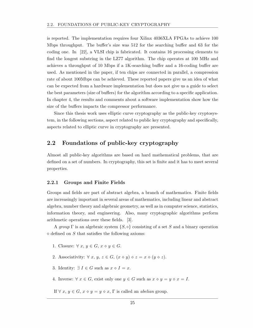
A group Γ is an algebraic system {S, ¦} consisting of a set S and a binary operation¦ defined on S that satisfies the following axioms:
1. Closure: ∀ x, y ∈ G, x ¦ y ∈ G.
2. Associativity: ∀ x, y, z ∈ G, (x ¦ y) ¦ z = x ¦ (y ¦ z).
3. Identity: ∃ I ∈ G such as x ¦ I = x.
4. Inverse: ∀ x ∈ G, exist only one y ∈ G such as x ¦ y = y ¦ x = I.
If ∀ x, y ∈ G, x ¦ y = y ¦ x, Γ is called an abelian group.
25
CHAPTER 2. LZ COMPRESSION AND ELLIPTIC CURVECRYPTOGRAPHY
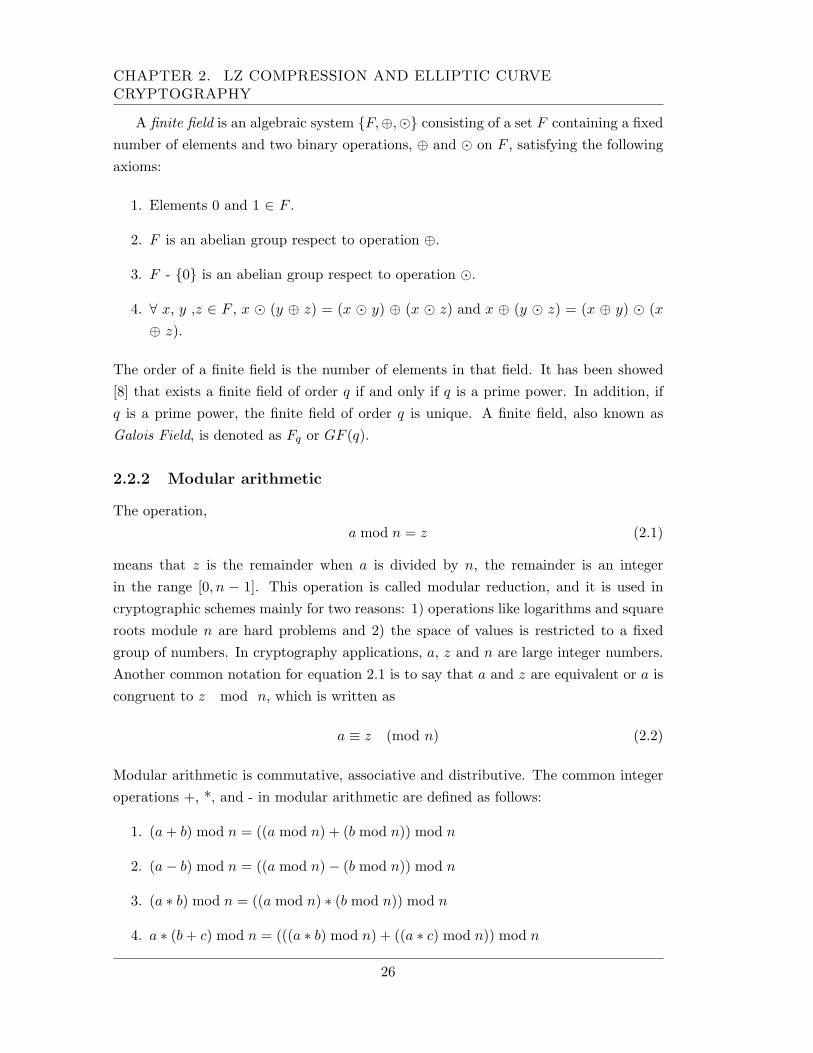
A finite field is an algebraic system {F,⊕,¯} consisting of a set F containing a fixednumber of elements and two binary operations, ⊕ and ¯ on F , satisfying the followingaxioms:
1. Elements 0 and 1 ∈ F .
2. F is an abelian group respect to operation ⊕.
3. F - {0} is an abelian group respect to operation ¯.
4. ∀ x, y ,z ∈ F , x ¯ (y ⊕ z) = (x ¯ y) ⊕ (x ¯ z) and x ⊕ (y ¯ z) = (x ⊕ y) ¯ (x⊕ z).
The order of a finite field is the number of elements in that field. It has been showed[8] that exists a finite field of order q if and only if q is a prime power. In addition, ifq is a prime power, the finite field of order q is unique. A finite field, also known asGalois Field, is denoted as Fq or GF (q).
2.2.2 Modular arithmetic
The operation,a mod n = z (2.1)
means that z is the remainder when a is divided by n, the remainder is an integerin the range [0, n − 1]. This operation is called modular reduction, and it is used incryptographic schemes mainly for two reasons: 1) operations like logarithms and squareroots module n are hard problems and 2) the space of values is restricted to a fixedgroup of numbers. In cryptography applications, a, z and n are large integer numbers.Another common notation for equation 2.1 is to say that a and z are equivalent or a iscongruent to z mod n, which is written as
a ≡ z (mod n) (2.2)
Modular arithmetic is commutative, associative and distributive. The common integeroperations +, *, and - in modular arithmetic are defined as follows:
1. (a + b) mod n = ((a mod n) + (b mod n)) mod n
2. (a− b) mod n = ((a mod n)− (b mod n)) mod n
3. (a ∗ b) mod n = ((a mod n) ∗ (b mod n)) mod n
4. a ∗ (b + c) mod n = (((a ∗ b) mod n) + ((a ∗ c) mod n)) mod n
26
2.2. FOUNDATIONS OF PUBLIC-KEY CRYPTOGRAPHY
Another important modular operation is the inversion. a−1 is the inverse mod n of anumber a if equivalence in equation 2.3 is true.
a ∗ a−1 ≡ 1 (mod n) (2.3)
For a given number a, a−1 is the unique solution only if a and n are relatively primes[4]. If n is a prime number, every number in the range [1, n− 1] is relatively prime to n
and has exactly one inverse (mod n). To calculate a module inverse, two algorithms arecommonly used: The Extended Euclidean Algorithm and the Fermat’s Little Theorem.These algorithms are described in next chapter.
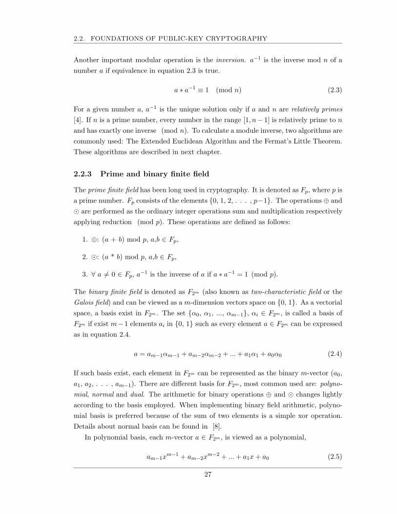
2.2.3 Prime and binary finite field
The prime finite field has been long used in cryptography. It is denoted as Fp, where p isa prime number. Fp consists of the elements {0, 1, 2, . . . , p−1}. The operations ⊕ and¯ are performed as the ordinary integer operations sum and multiplication respectivelyapplying reduction (mod p). These operations are defined as follows:
1. ⊕: (a + b) mod p, a,b ∈ Fp,
2. ¯: (a * b) mod p, a,b ∈ Fp,
3. ∀ a 6= 0 ∈ Fp, a−1 is the inverse of a if a ∗ a−1 = 1 (mod p).
The binary finite field is denoted as F2m (also known as two-characteristic field or theGalois field) and can be viewed as a m-dimension vectors space on {0, 1}. As a vectorialspace, a basis exist in F2m . The set {α0, α1, ..., αm−1}, αi ∈ F2m , is called a basis ofF2m if exist m−1 elements ai in {0, 1} such as every element a ∈ F2m can be expressedas in equation 2.4.
a = am−1αm−1 + am−2αm−2 + ... + a1α1 + a0α0 (2.4)
If such basis exist, each element in F2m can be represented as the binary m-vector (a0,a1, a2, . . . , am−1). There are different basis for F2m , most common used are: polyno-mial, normal and dual. The arithmetic for binary operations ⊕ and ¯ changes lightlyaccording to the basis employed. When implementing binary field arithmetic, polyno-mial basis is preferred because of the sum of two elements is a simple xor operation.Details about normal basis can be found in [8].
In polynomial basis, each m-vector a ∈ F2m , is viewed as a polynomial,
am−1xm−1 + am−2x
m−2 + ... + a1x + a0 (2.5)
27
CHAPTER 2. LZ COMPRESSION AND ELLIPTIC CURVECRYPTOGRAPHY
The binary field F2m is generated by an irreducible polynomial F (x) of grade m of theform
xm + fm−1xm−1 + fm−2x
m−2 + ... + f1x + f0 (2.6)
where fi ∈ {0, 1}. The polynomial is named irreducible because it can not be expressedas the multiplication of two other polynomials (it is as a prime number in integerarithmetic). The polynomial needs to be irreducible, otherwise the math does not work[4].
Let be a, b ∈ F2m , a = (am−1, am−2, ..., a1, a0) b = (bm−1, bm−2, ..., b1, b0). Thearithmetic operations ⊕ and ¯ in the finite field F2m are defined as follows:
1. ⊕: a ⊕ b = c, c = (cm−1, cm−2, ..., c1, c0), where ci = ai xor bi.
2. ¯: a ¯ b = c, c = (cm−1, cm−2, ..., c1, c0), where c(x) = a(x)b(x) mod F (x).c(x) = cm−1x
m−1 + cm−2xm−2 + ... + c1x + c0
a(x) = am−1xm−1 + am−2x
m−2 + ... + a1x + a0
b(x) = bm−1xm−1 + bm−2x
m−2 + ... + b1x + b0
For cryptographic applications, the irreducible polynomial F (x) is a trinomial of theform xm + xi + 1 or it is pentanomial of the form xm + xi + xj + xl + 1, where i, j andl are positive integers. The use of trinomials or pentanomials leads to efficient softwareand hardware implementations.
2.2.4 Security of public key cryptosystems
Different to symmetrical cryptography, where data transformation is carried out bypermutations and transpositions, in public key cryptography, almost all methods trans-form data by executing complex arithmetic operations on a finite field. This is becausethe security of these cryptosystems is based on conjectured very difficult problems, so,in order to break the cryptosystem, it is necessary to solve the underlying problem.The more difficult the problem on which one cryptosystem is based on, the higher thesecurity offered by the cryptosystem. In practice, two problems have been taken tobuild on them public key cryptosystems: the large integer factorization problem andthe logarithm discrete computation. The complexity of these two problems is a functionof the order of the finite field used. While cryptosystems based on integer factorizationare considered currently secure using 1024 bit operands, the cryptosystems based onlogarithm discrete problems offer an equivalent security level using 160-bit operands.
The logarithm discrete problem is defined on a finite group Γ= {S, ¦}. For a groupelement g ∈ S and a number n, let gn denote the element obtained by applying operation
28
2.3. ELLIPTIC CURVE CRYPTOGRAPHY (ECC)
¦ n times to g (g2 = g ¦ g, g3 = g ¦ g ¦ g, and so on). The discrete logarithm problem isas follows: given an element g ∈ S and another element h ∈ S, find an integer x suchthat gx = h.
The most widely public key cryptosystem, the RSA, is based on the integer fac-torization problem. Other public key cryptosystems like ElGammal, Diffie-Hellmankey exchange and DSA are based on the logarithm discrete problem defined on themultiplicative group modulo p, p is a large prime number.
For both, the integer factorization and the logarithm discrete problems exist al-gorithms for solving them running in sub-exponential time. This means that theseproblems are considered hard, but not as hard as those problems which admit onlyfully exponential time algorithms. In the following section, another hard mathematicalproblem is presented: the discrete logarithm problem defined on the group additive ofelliptic curve points.
2.3 Elliptic Curve Cryptography (ECC)
Elliptic curves, as geometric algebraic entities have been studied since the second half ofnineteen century, initially, without any cryptographic purpose. In 1985, application ofelliptic curves in public key cryptography was independently proposed by Neals Koblitz[24] and Victor Miller [25].
Koblitz and Miller proposed to use an elliptic curve (see definition in next section)defined on a finite field, and to define a point addition operation such that the pointsof the elliptic curve and the point addition operation formed an abelian group. Onthis group, the discrete logarithm problem, called the elliptic curve discrete logarithmproblem (ECLDP), can be defined and so, a cryptosystem could be built on this problem.The advantages of this elliptic curve cryptosystem is that the ECLDP is more difficultto solve than that defined on the multiplicative group Fp. The best algorithm knownfor solving the ECDLP is fully exponential, the Pollar-Rho method [26].
ECC can offer a similar security level than other public key criptosystems usingshorter length keys, which implies less space for key storage, time saving when keys aretransmitted and modular computations less costly. ECC’s security has not been proved;its strength is based on the inability to find attacks.
2.3.1 The elliptic curve group
An elliptic curve is a set of points (x, y) that satisfies an equation. Although the curvecan be defined on any domain, for cryptographic applications, it must be defined on a
29
CHAPTER 2. LZ COMPRESSION AND ELLIPTIC CURVECRYPTOGRAPHY
finite field Fq. If it is defined on Fp the elliptic curve equation is
y2 = x3 + ax + b (2.7)
When the elliptic curve is defined on the binary field, the equation is
y2 + xy = x3 + ax2 + b (2.8)
In both cases, a, b are in the finite field. Because all arithmetic is performed asdefined in the underlying finite field, x, y are finite field elements too. Let EC(Fq)denote the points of the elliptic curve defined on the finite field Fq. Because a Fq isfinite, EC(Fq) is also a finite set. In order to build a group from EC(Fq), a closureoperation on EC(Fq) must be defined. The operation is the sum of points and itsdefinition has a geometrical interpretation. The sum can involve equal or differentpoints. For equal points, the sum is known as DOUBLE and for different points, it isknown as ADD. Each of these operations is carried out in different way and its definitiondepends on the finite field on which the elliptic curve is defined.
In the case of the finite field Fp, ADD and DOUBLE operations are defined asfollows:
Let a, b ∈ Fp satisfying 4a3 + 27b2 6= 0. Let P, Q, R ∈ E(Fp), P = (x1, y1) Q =(x2, y2) R = (x3, y3). The system {E(Fp) ∪ {O},+} forms an abelian group respect to+ operation, defined as
1. P + O = O + P = P , ∀P ∈ E(Fp)
2. If P 6= ±Q, ADD(P , Q) = P + Q = R, wherex3 = λ2 − x1 − x2
y3 = λ(x1 − x3)− y1
λ = (y2 − y1)/(x2 − x1)
3. If P = Q, DOUBLE(P ) = P + Q = 2P = R, wherex3 = λ2 − 2x1
y3 = λ(x1 − x3)− y1
λ = (3x21 + a)/2y1
So, an ADD operation requires one inversion, two multiplications, one squaringoperation and six sums, all of them operation on Fp. A DOUBLE operation requiresone extra squaring and two extra sums.
For the case of the F2m finite field, let a, b ∈ F2m . Let P, Q, R ∈ E(F2m), P = (x1, y1)Q = (x2, y2) R = (x3, y3). The system {E(F2m)∪{O}, +} forms an abelian group respectto + operation, defined as
30
2.3. ELLIPTIC CURVE CRYPTOGRAPHY (ECC)
1. P + O = O + P = P , ∀P ∈ E(F2m)
2. If P 6= ±Q, ADD(P , Q) = P + Q = R, wherex3 = λ2 + λ + x1 + x2 + a
y3 = λ(x1 + x3) + x3 + y1
λ = (y2 + y1)/(x2 + x1)
3. If P = Q, DOUBLE(P ) = P + Q = 2P = R, wherex3 = λ2 + λ + a
y3 = x21 + λx3 + x3
λ = x1 + y1/x1
In this case, ADD requires one inversion, two multiplications, one squaring andeight additions. For DOUBLE operation, it requires five additions, two squaring, twomultiplications and one inversion, all of them, operations on F2m .
Either if the elliptic curve is defined on the prime Fp or binary F2m finite fields, thesum of points is the group operation where the ECDLP is defined. The ECDLP consiston given two points P , Q ∈ E(Fq), to find the positive integer k such as Q = kP . Ascommented in section 2.2.4, this problem is of exponential complexity. On the contrary,knowing the scalar k and the point P , the operation kP is relative easy to compute.The operation kP is the main and most time consuming operation in all cryptographicschemes built on elliptic curves. The operation kP is computed as accumulative sumoperation of point P with itself. These sum operations can be either ADD or DOUBLEoperations, the efficient computation of these operations impacts the execution timeof the scalar multiplications and also, the execution of the cryptographic schemes. Ithas been shown in the literature that the finite field used do no affect the security ofthe elliptic curve cryptosystems but their performance. It is considered that ellipticcurves defined on the binary field F2m leads to efficient implementation of the fieldarithmetic. There exist curves on which the ECDLP is easy to solve [8], the so-calledsupersingular curves have to be avoided. These curves have an equal number of pointsthat the finite field on which they are defined. The National Institute of Standardsand Technology (NIST) has emitted several recommendations and has proposed severalelliptic curves over both Fp and F2m for cryptographic applications. Different to othercryptosystems, the security of ECC not only depends on the length of the key but alsoin other parameters like the elliptic curve being used.
2.3.2 Cryptographic schemes
An elliptic curve cryptosystem consist in a tuple. If the elliptic curve is defined on Fp,the cryptosystem domain parameters are the six-tuple DFp = (p, a, b,G, n, h), p is the
31
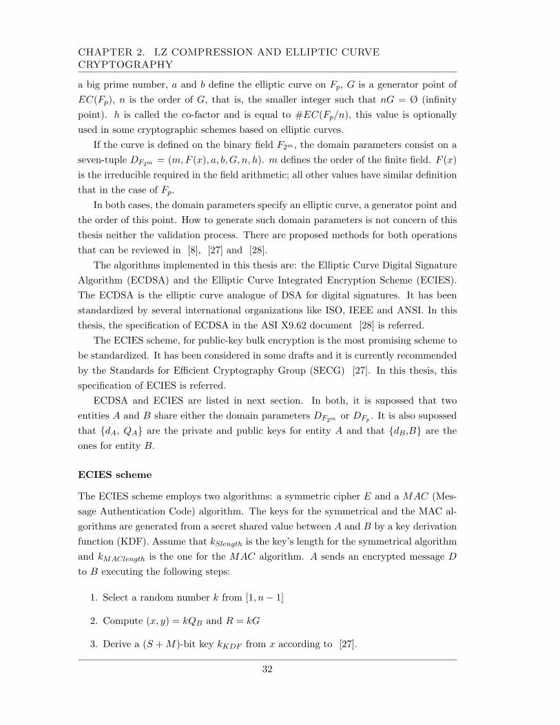
CHAPTER 2. LZ COMPRESSION AND ELLIPTIC CURVECRYPTOGRAPHY
a big prime number, a and b define the elliptic curve on Fp, G is a generator point ofEC(Fp), n is the order of G, that is, the smaller integer such that nG = Ø (infinitypoint). h is called the co-factor and is equal to #EC(Fp/n), this value is optionallyused in some cryptographic schemes based on elliptic curves.
If the curve is defined on the binary field F2m , the domain parameters consist on aseven-tuple DF2m = (m,F (x), a, b, G, n, h). m defines the order of the finite field. F (x)is the irreducible required in the field arithmetic; all other values have similar definitionthat in the case of Fp.
In both cases, the domain parameters specify an elliptic curve, a generator point andthe order of this point. How to generate such domain parameters is not concern of thisthesis neither the validation process. There are proposed methods for both operationsthat can be reviewed in [8], [27] and [28].
The algorithms implemented in this thesis are: the Elliptic Curve Digital SignatureAlgorithm (ECDSA) and the Elliptic Curve Integrated Encryption Scheme (ECIES).The ECDSA is the elliptic curve analogue of DSA for digital signatures. It has beenstandardized by several international organizations like ISO, IEEE and ANSI. In thisthesis, the specification of ECDSA in the ASI X9.62 document [28] is referred.
The ECIES scheme, for public-key bulk encryption is the most promising scheme tobe standardized. It has been considered in some drafts and it is currently recommendedby the Standards for Efficient Cryptography Group (SECG) [27]. In this thesis, thisspecification of ECIES is referred.
ECDSA and ECIES are listed in next section. In both, it is supossed that twoentities A and B share either the domain parameters DF2m or DFp . It is also supossedthat {dA, QA} are the private and public keys for entity A and that {dB,B} are theones for entity B.
ECIES scheme
The ECIES scheme employs two algorithms: a symmetric cipher E and a MAC (Mes-sage Authentication Code) algorithm. The keys for the symmetrical and the MAC al-gorithms are generated from a secret shared value between A and B by a key derivationfunction (KDF). Assume that kSlength is the key’s length for the symmetrical algorithmand kMAClength is the one for the MAC algorithm. A sends an encrypted message D
to B executing the following steps:
1. Select a random number k from [1, n− 1]
2. Compute (x, y) = kQB and R = kG
3. Derive a (S + M)-bit key kKDF from x according to [27].
32
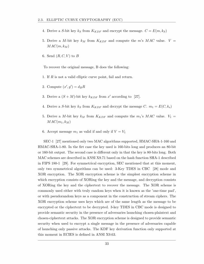
2.3. ELLIPTIC CURVE CRYPTOGRAPHY (ECC)
4. Derive a S-bit key kS from KKDF and encrypt the message. C = E(m, kS)
5. Derive a M -bit key kM from KKDF and compute the m’s MAC value. V =MAC(m, kM )
6. Send (R, C, V ) to B
To recover the original message, B does the following:
1. If R is not a valid elliptic curve point, fail and return.
2. Compute (x′, y′) = dBR
3. Derive a (S + M)-bit key kKDF from x′ according to [27].
4. Derive a S-bit key kS from KKDF and decrypt the message C. m1 = E(C, ks)
5. Derive a M -bit key kM from KKDF and compute the m1’s MAC value. V1 =MAC(m1, kM )
6. Accept message m1 as valid if and only if V = V1
SEC-1 [27] mentioned only two MAC algorithms supported, HMAC-SHA-1-160 andHMAC-SHA-1-80. In the firt case the key used is 160-bits long and produces an 80-bitor 160-bit output. The second case is different only in that the key is 80-bits long. BothMAC schemes are described in ANSI X9.71 based on the hash function SHA-1 describedin FIPS 180-1 [29]. For symmetrical encryption, SEC mentioned that at this moment,only two symmetrical algorithms can be used: 3-Key TDES in CBC [28] mode andXOR encryption. The XOR encryption scheme is the simplest encryption scheme inwhich encryption consists of XORing the key and the message, and decryption consistsof XORing the key and the ciphertext to recover the message. The XOR scheme iscommonly used either with truly random keys when it is known as the ’one-time pad’,or with pseudorandom keys as a component in the construction of stream ciphers. TheXOR encryption scheme uses keys which are of the same length as the message to beencrypted or the ciphertext to be decrypted. 3-key TDES in CBC mode is designed toprovide semantic security in the presence of adversaries launching chosen-plaintext andchosen-ciphertext attacks. The XOR encryption scheme is designed to provide semanticsecurity when used to encrypt a single message in the presence of adversaries capableof launching only passive attacks. The KDF key derivation function only supported atthis moment in ECIES is defined in ANSI X9.63.
33
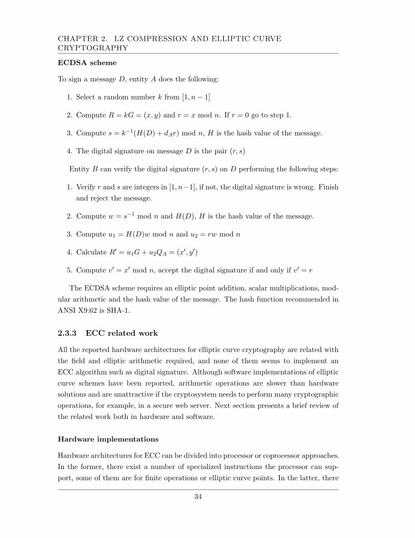
CHAPTER 2. LZ COMPRESSION AND ELLIPTIC CURVECRYPTOGRAPHY
ECDSA scheme
To sign a message D, entity A does the following:
1. Select a random number k from [1, n− 1]
2. Compute R = kG = (x, y) and r = x mod n. If r = 0 go to step 1.
3. Compute s = k−1(H(D) + dAr) mod n, H is the hash value of the message.
4. The digital signature on message D is the pair (r, s)
Entity B can verify the digital signature (r, s) on D performing the following steps:
1. Verify r and s are integers in [1, n−1], if not, the digital signature is wrong. Finishand reject the message.
2. Compute w = s−1 mod n and H(D), H is the hash value of the message.
3. Compute u1 = H(D)w mod n and u2 = rw mod n
4. Calculate R′ = u1G + u2QA = (x′, y′)
5. Compute v′ = x′ mod n, accept the digital signature if and only if v′ = r
The ECDSA scheme requires an elliptic point addition, scalar multiplications, mod-ular arithmetic and the hash value of the message. The hash function recommended inANSI X9.62 is SHA-1.
2.3.3 ECC related work
All the reported hardware architectures for elliptic curve cryptography are related withthe field and elliptic arithmetic required, and none of them seems to implement anECC algorithm such as digital signature. Although software implementations of ellipticcurve schemes have been reported, arithmetic operations are slower than hardwaresolutions and are unattractive if the cryptosystem needs to perform many cryptographicoperations, for example, in a secure web server. Next section presents a brief review ofthe related work both in hardware and software.
Hardware implementations
Hardware architectures for ECC can be divided into processor or coprocessor approaches.In the former, there exist a number of specialized instructions the processor can sup-port, some of them are for finite operations or elliptic curve points. In the latter, there
34
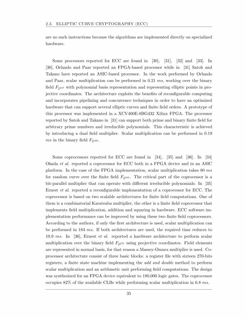
2.3. ELLIPTIC CURVE CRYPTOGRAPHY (ECC)
are no such instructions because the algorithms are implemented directly on specializedhardware.
Some processors reported for ECC are found in [30], [31], [32] and [33]. In[30], Orlando and Paar reported an FPGA-based processor while in [31] Satoh andTakano have reported an ASIC-based processor. In the work performed by Orlandoand Paar, scalar multiplication can be performed in 0.21 ms, working over the binaryfield F2167 with polynomial basis representation and representing elliptic points in pro-jective coordinates. The architecture exploits the benefits of reconfigurable computingand incorporates pipelining and concurrence techniques in order to have an optimizedhardware that can support several elliptic curves and finite field orders. A prototype ofthis processor was implemented in a XCV400E-8BG432 Xilinx FPGA. The processorreported by Satoh and Takano in [31] can support both prime and binary finite field forarbitrary prime numbers and irreducible polynomials. This characteristic is achievedby introducing a dual field multiplier. Scalar multiplication can be performed in 0.19ms in the binary field F2160 .
Some coprocessors reported for ECC are found in [34], [35] and [36]. In [34]Okada et al. reported a coprocessor for ECC both in a FPGA device and in an ASICplatform. In the case of the FPGA implementation, scalar multiplication takes 80 ms
for random curve over the finite field F2163 . The critical part of the coprocessor is abit-parallel multiplier that can operate with different irreducible polynomials. In [35]Ernest et al. reported a reconfigurable implementation of a coprocessor for ECC. Thecoprocessor is based on two scalable architectures for finite field computations. One ofthem is a combinatorial Karatsuba multiplier, the other is a finite field coprocessor thatimplements field multiplication, addition and squaring in hardware. ECC software im-plementation performance can be improved by using these two finite field coprocessors.According to the authors, if only the first architecture is used, scalar multiplication canbe performed in 184 ms. If both architectures are used, the required time reduces to10.9 ms. In [36], Ernest et al. reported a hardware architecture to perform scalarmultiplication over the binary field F2270 using projective coordinates. Field elementsare represented in normal basis, for that reason a Massey-Omura multiplier is used. Co-processor architecture consist of three basic blocks: a register file with sixteen 270-bitsregisters, a finite state machine implementing the add and double method to performscalar multiplication and an arithmetic unit performing field computations. The designwas synthesized for an FPGA device equivalent to 180,000 logic gates. The coprocessoroccupies 82% of the available CLBs while performing scalar multiplication in 6.8 ms.
35
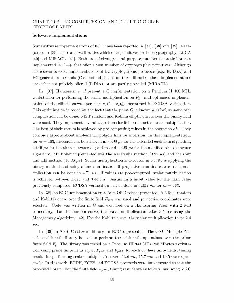
CHAPTER 2. LZ COMPRESSION AND ELLIPTIC CURVECRYPTOGRAPHY
Software implementations
Some software implementations of ECC have been reported in [37], [38] and [39]. As re-ported in [39], there are two libraries which offer primitives for EC cryptography: LiDIA[40] and MIRACL [41]. Both are efficient, general purpose, number-theoretic librariesimplemented in C++ that offer a vast number of cryptographic primitives. Althoughthere seem to exist implementations of EC cryptographic protocols (e.g., ECDSA) andEC generation methods (CM method) based on these libraries, these implementationsare either not publicly offered (LiDIA), or are partly provided (MIRACL).
In [37], Hankerson et al present a C implementation on a Pentium II 400 MHzworkstation for performing the scalar multiplication on F2m and optimized implemen-tation of the elliptic curve operation u1G + u2QA performed in ECDSA verification.This optimization is based on the fact that the point G is known a priori, so some pre-computation can be done. NIST random and Koblitz elliptic curves over the binary fieldwere used. They implement several algorithms for field arithmetic scalar multiplication.The best of their results is achieved by pre-computing values in the operation kP . Theyconclude aspects about implementing algorithms for inversion. In this implementation,for m = 163, inversion can be achieved in 30.99 µs for the extended euclidean algorithm,42.49 µs for the almost inverse algorithm and 40.26 µs for the modified almost inversealgorithm. Multiplier implemented was the Karatsuba method (3.92 µs) and the shiftand add method (16.36 µs). Scalar multiplication is executed in 9.178 ms applying thebinary method and using affine coordinates. If projective coordinates are used, mul-tiplication can be done in 4.71 µs. If values are pre-computed, scalar multiplicationis achieved between 1.683 and 3.44 ms. Assuming a m-bit value for the hash valuepreviously computed, ECDSA verification can be done in 5.005 ms for m = 163.
In [38], an ECC implementation on a Palm OS Device is presented. A NIST (randomand Koblitz) curve over the finite field F2163 was used and projective coordinates wereselected. Code was written in C and executed on a Handspring Visor with 2 MBof memory. For the random curve, the scalar multiplication takes 3.5 sec using theMontgomery algorithm [42]. For the Koblitz curve, the scalar multiplication takes 2.4sec.
In [39] an ANSI C software library for ECC is presented. The GNU Multiple Pre-cision arithmetic library is used to perform the arithmetic operations over the primefinite field Fp. The library was tested on a Pentium III 933 MHz 256 Mbytes worksta-tion using prime finite fields Fp175 , Fp192 and Fp224 ; for each of these finite fields, timingresults for performing scalar multiplication were 13.6 ms, 15.7 ms and 19.5 ms respec-tively. In this work, ECDH, ECES and ECDSA protocols were implemented to test theproposed library. For the finite field Fp192 , timing results are as follows: assuming MAC
36
2.4. SUMMARY OF THE CHAPTER
value previously computed, ECES encryption takes 36.5 ms, ECDSA digital signaturegeneration takes 22.7 ms and 28.3 ms for verification.
Because of elliptic curve cryptographic algorithms perform a high amount of math-ematical operations with large numbers in a finite field; implementing ECC with theavailable instruction set of a general purpose processor is inefficient, as mentioned inthe software implementations. For this reason, and the advantages of a hardware im-plementation, this last solution seems to be better suited for ECC algorithms.
2.4 Summary of the Chapter
In this Chapter, the basic background of this research work was exposed. Some theo-retical aspects of lossless compression, cryptography and elliptic curves were described.In the following Chapter, the architecture of the system in presented based on the bestdecision made according to the delimitations of the design.
37
CHAPTER 2. LZ COMPRESSION AND ELLIPTIC CURVECRYPTOGRAPHY
38
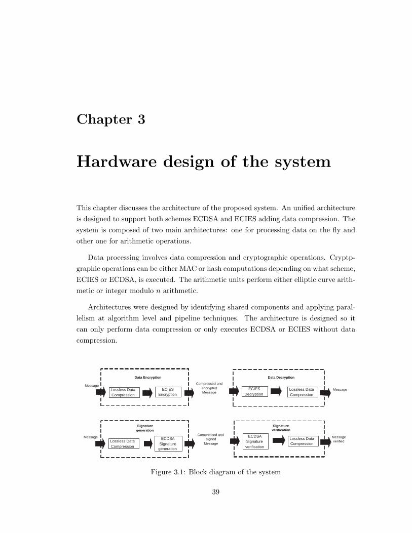
Chapter 3
Hardware design of the system
This chapter discusses the architecture of the proposed system. An unified architectureis designed to support both schemes ECDSA and ECIES adding data compression. Thesystem is composed of two main architectures: one for processing data on the fly andother one for arithmetic operations.
Data processing involves data compression and cryptographic operations. Cryptp-graphic operations can be either MAC or hash computations depending on what scheme,ECIES or ECDSA, is executed. The arithmetic units perform either elliptic curve arith-metic or integer modulo n arithmetic.
Architectures were designed by identifying shared components and applying paral-lelism at algorithm level and pipeline techniques. The architecture is designed so itcan only perform data compression or only executes ECDSA or ECIES without datacompression.
Message ECIES
Encryption
Data Encryption
Lossless Data Compression
Compressed and encrypted Message
ECIES Decryption
Data Decryption
Lossless Data Compression
Message
Message ECDSA Signature
generation
Signature generation
Lossless Data Compression
Compressed and signed
Message Lossless Data Compression
Message verified
ECDSA Signature verification
Signature verification
Figure 3.1: Block diagram of the system
39
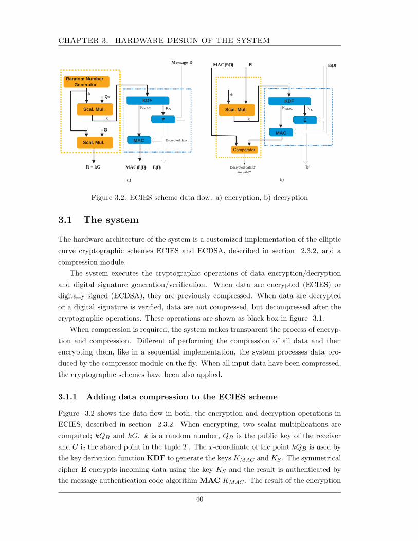
CHAPTER 3. HARDWARE DESIGN OF THE SYSTEM
Q B
Scal. Mul.
Random Number Generator
KDF
E
MAC
G
R = kG MAC ( E( D ) ) E( D )
Message D
K S K MAC
x
k
Scal. Mul. Encrypted data
a)
R
Scal. Mul.
KDF
E
MAC
D’
K S K MAC
x
d B
b)
MAC ( E( D ) ) E( D )
Comparator
Decrypted data D’
are valid?
Figure 3.2: ECIES scheme data flow. a) encryption, b) decryption
3.1 The system
The hardware architecture of the system is a customized implementation of the ellipticcurve cryptographic schemes ECIES and ECDSA, described in section 2.3.2, and acompression module.
The system executes the cryptographic operations of data encryption/decryptionand digital signature generation/verification. When data are encrypted (ECIES) ordigitally signed (ECDSA), they are previously compressed. When data are decryptedor a digital signature is verified, data are not compressed, but decompressed after thecryptographic operations. These operations are shown as black box in figure 3.1.
When compression is required, the system makes transparent the process of encryp-tion and compression. Different of performing the compression of all data and thenencrypting them, like in a sequential implementation, the system processes data pro-duced by the compressor module on the fly. When all input data have been compressed,the cryptographic schemes have been also applied.
3.1.1 Adding data compression to the ECIES scheme
Figure 3.2 shows the data flow in both, the encryption and decryption operations inECIES, described in section 2.3.2. When encrypting, two scalar multiplications arecomputed; kQB and kG. k is a random number, QB is the public key of the receiverand G is the shared point in the tuple T . The x-coordinate of the point kQB is used bythe key derivation function KDF to generate the keys KMAC and KS . The symmetricalcipher E encrypts incoming data using the key KS and the result is authenticated bythe message authentication code algorithm MAC KMAC . The result of the encryption
40
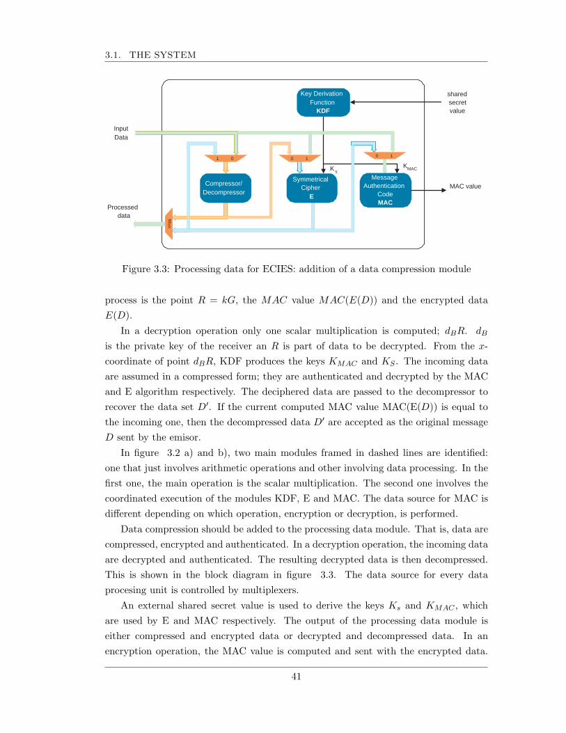
3.1. THE SYSTEM
shared secret value
0 1
K s
MAC value
Input Data
0 1 1 0
M u x
Key Derivation Function
KDF
Compressor/ Decompressor
Symmetrical Cipher
E
Message Authentication
Code MAC
Processed data
K MAC
Figure 3.3: Processing data for ECIES: addition of a data compression module
process is the point R = kG, the MAC value MAC(E(D)) and the encrypted dataE(D).
In a decryption operation only one scalar multiplication is computed; dBR. dB
is the private key of the receiver an R is part of data to be decrypted. From the x-coordinate of point dBR, KDF produces the keys KMAC and KS . The incoming dataare assumed in a compressed form; they are authenticated and decrypted by the MACand E algorithm respectively. The deciphered data are passed to the decompressor torecover the data set D′. If the current computed MAC value MAC(E(D)) is equal tothe incoming one, then the decompressed data D′ are accepted as the original messageD sent by the emisor.
In figure 3.2 a) and b), two main modules framed in dashed lines are identified:one that just involves arithmetic operations and other involving data processing. In thefirst one, the main operation is the scalar multiplication. The second one involves thecoordinated execution of the modules KDF, E and MAC. The data source for MAC isdifferent depending on which operation, encryption or decryption, is performed.
Data compression should be added to the processing data module. That is, data arecompressed, encrypted and authenticated. In a decryption operation, the incoming dataare decrypted and authenticated. The resulting decrypted data is then decompressed.This is shown in the block diagram in figure 3.3. The data source for every dataprocesing unit is controlled by multiplexers.
An external shared secret value is used to derive the keys Ks and KMAC , whichare used by E and MAC respectively. The output of the processing data module iseither compressed and encrypted data or decrypted and decompressed data. In anencryption operation, the MAC value is computed and sent with the encrypted data.
41
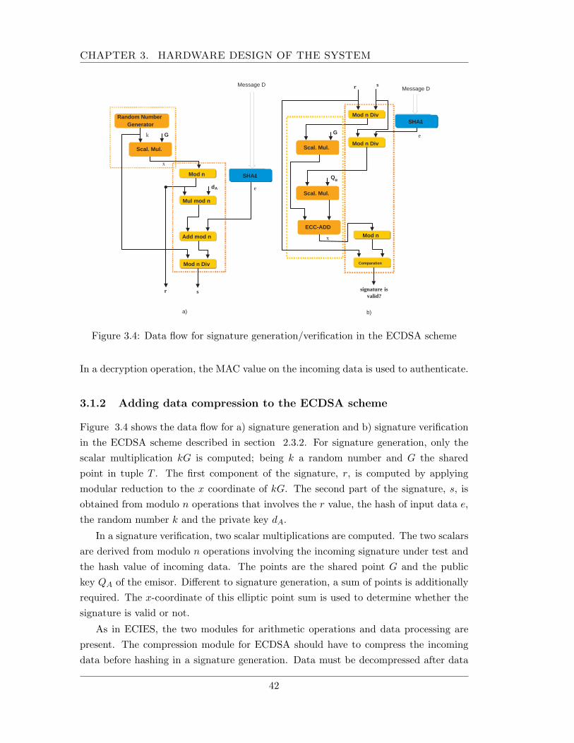
CHAPTER 3. HARDWARE DESIGN OF THE SYSTEM
SHA - 1
s
Add mod n
Mul mod n
d A
Mod n Div
G
r
Mod n
k
x
e
Random Number Generator
Scal. Mul.
Message D s r
Mod n Div
G
Mod n Div
Mod n
Comparation
Q B
signature is valid?
x
Message D
Scal. Mul.
ECC-ADD
Scal. Mul.
SHA - 1
e
a) b)
Figure 3.4: Data flow for signature generation/verification in the ECDSA scheme
In a decryption operation, the MAC value on the incoming data is used to authenticate.
3.1.2 Adding data compression to the ECDSA scheme
Figure 3.4 shows the data flow for a) signature generation and b) signature verificationin the ECDSA scheme described in section 2.3.2. For signature generation, only thescalar multiplication kG is computed; being k a random number and G the sharedpoint in tuple T . The first component of the signature, r, is computed by applyingmodular reduction to the x coordinate of kG. The second part of the signature, s, isobtained from modulo n operations that involves the r value, the hash of input data e,the random number k and the private key dA.
In a signature verification, two scalar multiplications are computed. The two scalarsare derived from modulo n operations involving the incoming signature under test andthe hash value of incoming data. The points are the shared point G and the publickey QA of the emisor. Different to signature generation, a sum of points is additionallyrequired. The x-coordinate of this elliptic point sum is used to determine whether thesignature is valid or not.
As in ECIES, the two modules for arithmetic operations and data processing arepresent. The compression module for ECDSA should have to compress the incomingdata before hashing in a signature generation. Data must be decompressed after data
42
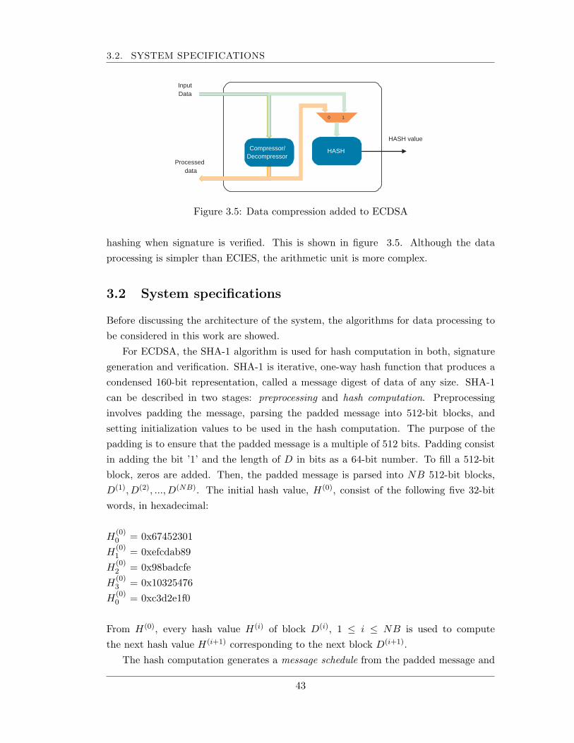
3.2. SYSTEM SPECIFICATIONS
HASH value
Input Data
Compressor/ Decompressor
HASH
Processed data
0 1
Figure 3.5: Data compression added to ECDSA
hashing when signature is verified. This is shown in figure 3.5. Although the dataprocessing is simpler than ECIES, the arithmetic unit is more complex.
3.2 System specifications
Before discussing the architecture of the system, the algorithms for data processing tobe considered in this work are showed.
For ECDSA, the SHA-1 algorithm is used for hash computation in both, signaturegeneration and verification. SHA-1 is iterative, one-way hash function that produces acondensed 160-bit representation, called a message digest of data of any size. SHA-1can be described in two stages: preprocessing and hash computation. Preprocessinginvolves padding the message, parsing the padded message into 512-bit blocks, andsetting initialization values to be used in the hash computation. The purpose of thepadding is to ensure that the padded message is a multiple of 512 bits. Padding consistin adding the bit ’1’ and the length of D in bits as a 64-bit number. To fill a 512-bitblock, zeros are added. Then, the padded message is parsed into NB 512-bit blocks,D(1), D(2), ..., D(NB). The initial hash value, H(0), consist of the following five 32-bitwords, in hexadecimal:
H(0)0 = 0x67452301
H(0)1 = 0xefcdab89
H(0)2 = 0x98badcfe
H(0)3 = 0x10325476
H(0)0 = 0xc3d2e1f0
From H(0), every hash value H(i) of block D(i), 1 ≤ i ≤ NB is used to computethe next hash value H(i+1) corresponding to the next block D(i+1).
The hash computation generates a message schedule from the padded message and
43
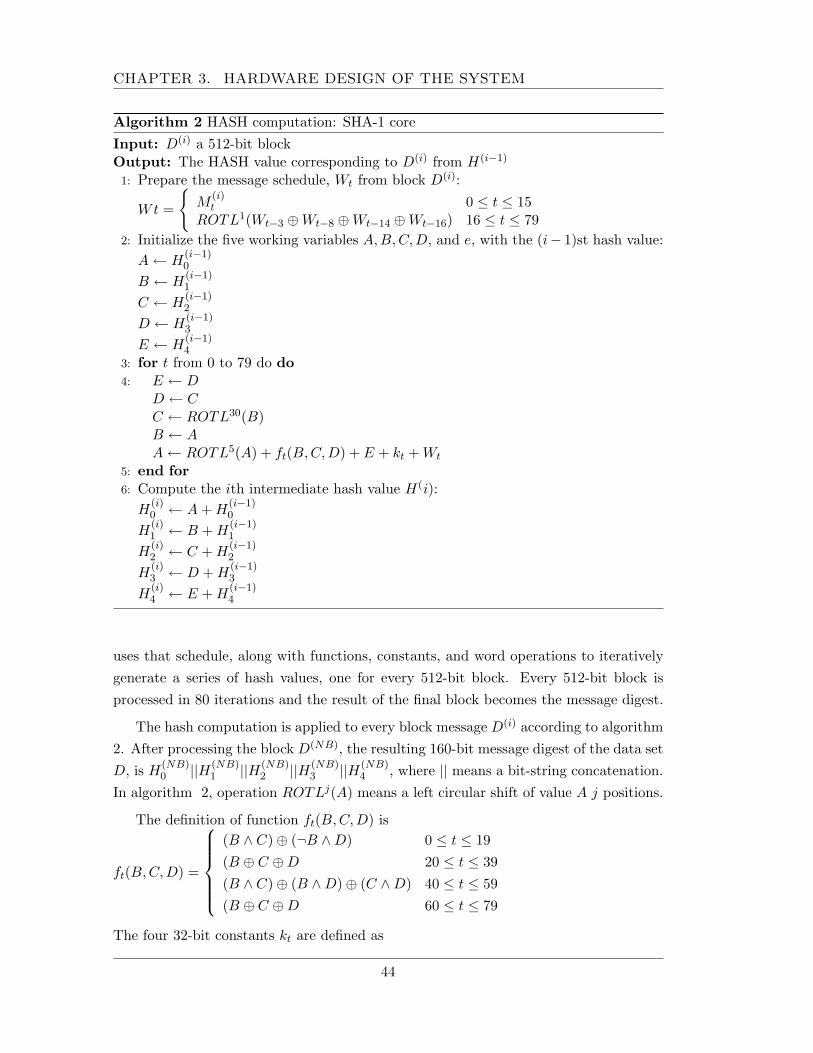
CHAPTER 3. HARDWARE DESIGN OF THE SYSTEM
Algorithm 2 HASH computation: SHA-1 coreInput: D(i) a 512-bit blockOutput: The HASH value corresponding to D(i) from H(i−1)
1: Prepare the message schedule, Wt from block D(i):
Wt =
{M
(i)t 0 ≤ t ≤ 15
ROTL1(Wt−3 ⊕Wt−8 ⊕Wt−14 ⊕Wt−16) 16 ≤ t ≤ 792: Initialize the five working variables A,B, C, D, and e, with the (i− 1)st hash value:
A ← H(i−1)0
B ← H(i−1)1
C ← H(i−1)2
D ← H(i−1)3
E ← H(i−1)4
3: for t from 0 to 79 do do4: E ← D
D ← CC ← ROTL30(B)B ← AA ← ROTL5(A) + ft(B, C,D) + E + kt + Wt
5: end for6: Compute the ith intermediate hash value H(i):
H(i)0 ← A + H
(i−1)0
H(i)1 ← B + H
(i−1)1
H(i)2 ← C + H
(i−1)2
H(i)3 ← D + H
(i−1)3
H(i)4 ← E + H
(i−1)4
uses that schedule, along with functions, constants, and word operations to iterativelygenerate a series of hash values, one for every 512-bit block. Every 512-bit block isprocessed in 80 iterations and the result of the final block becomes the message digest.
The hash computation is applied to every block message D(i) according to algorithm2. After processing the block D(NB), the resulting 160-bit message digest of the data setD, is H
(NB)0 ||H(NB)
1 ||H(NB)2 ||H(NB)
3 ||H(NB)4 , where || means a bit-string concatenation.
In algorithm 2, operation ROTLj(A) means a left circular shift of value A j positions.
The definition of function ft(B,C, D) is
ft(B,C, D) =
(B ∧ C)⊕ (¬B ∧D) 0 ≤ t ≤ 19(B ⊕ C ⊕D 20 ≤ t ≤ 39(B ∧ C)⊕ (B ∧D)⊕ (C ∧D) 40 ≤ t ≤ 59(B ⊕ C ⊕D 60 ≤ t ≤ 79
The four 32-bit constants kt are defined as
44

3.2. SYSTEM SPECIFICATIONS
kt =
0x5a827999 0 ≤ t ≤ 190x6ed9eba1 20 ≤ t ≤ 390x8f1bbcdc 40 ≤ t ≤ 590xca62c1d6 60 ≤ t ≤ 79
The key derivation function KDF considered is this work is specified in ANSI X9.63.KDF uses a shared secret Z to derive a bit-string of arbitrary length by executing theSHA-1 algorithm dlength/160e times. The bit-string is formed by concatenating thehash result in each iteration. Algorithm 3 lists the steps of KDF.
Algorithm 3 Key derivation function KDFInput: An octet string Z which is the shared secret value.Input: An integer keydatalen which is the length in octets of the keying data to be
generated.Output: The keying data Key which is an octet string of length keydatalen octets, or
’invalid’.1: Check that Z + 4 < hashmaxlen. If not, output ’invalid’ and stop.2: Initialize a big endian 4-octet string counter as 00000001HEX
3: for i from 1 to dkeydatalength/hashlene do4: ki ← HASH(Z||Counter)5: counter ← counter + 16: end for7: Key is the bit-string K1||K2...Kdkeydatalength/hashlene trunctated to keydatalength
octects.
The hash value computed in step 5 in algorithm 3 is on fixed size data. In everyiteration, only the value of the counter changes, so, the 512-bit block can initially bepadded and then the part corresponding to the counter can be updated.
For message authentication code MAC, the HMAC-SHA-1-160, specified in ANSIX9.71 is selected. It uses a 160-bit KMAC key and the SHA-1 algorithm for hash-ing. HMAC ensures that secure data is not corrupted in transit over unsecure chan-nels (like the internet) and is used in ECIES operations. HMAC generates a Mes-sage Authentication Code using the following formula: HMAC(D)= HASH[(KMAC ⊕opad)||HASH[(KMAC ⊕ ipad)||D]],where
45
CHAPTER 3. HARDWARE DESIGN OF THE SYSTEM
D = MessageH = Underlying Hash functionKMAC = Secret Keyopad = 0x36, repeated as neededipad = 0x5C, repeated as needed|| = concatenation operator⊕ = XOR operation
SHA-1 computes the hash value on two different data sets. First, SHA-1 is applied tothe bit string D1 = (kMAC ⊕ ipad) ‖ D). The second data set is D2 = (kMAC ⊕ opad) ‖SHA-1(D1).
HMAC(D) is then sent as any typical MAC(D) in a message transaction over in-secure channels. HMAC has all of the general properties of a MAC function and it iscomputationally very fast and very compact.
The symmetrical encryption algorithm E is the XORing encryption. This kind ofencryption consist in a XOR operation between the key KS and data, so, KS should beof be the same as the input data. So, KDF needs to generate a 160-bit KMAC key anda KS key of the same length that the message to be encrypted/decrypted.
Based on the previous specifications, next section describes an unified architecturethat gives support to ECIES and ECDSA for data processing.
In both ECIES, and ECDSA, the elliptic curve is defined on the binary field F2m
using polynomial basis. Based on the literature reviewed, this field leads to an effi-cient hardware implementation. Algorithms for performing these operations and theirarchitectures are described in the last section of this chapter.
3.3 Unified architecture for data processing and data flow
The architecture for data processing consists of four main modules:
• A data compressor module that implements a variant of the first algorithmLZ to compress/decompress data.
• A KDF module that implements the KDF algorithm to generate the keys KMAC
and KS .
• A simmetrical cipher E module that encrypts and decrypts data by XORingdata with key KS .
• An HMAC module that implements the HMAC algorithm for message authenti-cation code generation. In ECDSA operations, this unit computes not the MACbut the HASH value of input data.
46
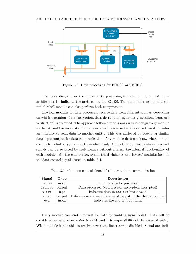
3.3. UNIFIED ARCHITECTURE FOR DATA PROCESSING AND DATA FLOW
shared secret value
0 1 Key
MAC/HASH value
Input Data
0 1 1 0
M u x
Key Derivation Function
SHA-1 core
Compressor/ Decompressor
Symmetrical Cipher MAC/HASH
SHA-1 core Processed
data
Figure 3.6: Data processing for ECDSA and ECIES
The block diagram for the unified data processing is shown in figure 3.6. Thearchitecture is similar to the architecture for ECIES. The main difference is that theinitial MAC module can also perform hash computation.
The four modules for data processing receive data from different sources, dependingon which operation (data encryption, data decryption, signature generation, signatureverification) is executed. The approach followed in this work was to design every moduleso that it could receive data from any external device and at the same time it providesan interface to send data to another entity. This was achieved by providing similardata input/output for data communication. Any module does not know where data iscoming from but only processes them when ready. Under this approach, data and controlsignals can be switched by multiplexers without altering the internal functionality ofeach module. So, the compressor, symmetrical cipher E and HMAC modules includethe data control signals listed in table 3.1.
Table 3.1: Common control signals for internal data communication
Signal Type Descriptiondat in input Input data to be processeddat out output Data processed (compressed, encrypted, decrypted)v dat inpt Indicates data in dat out bus is validm dat output Indicates new source data must be put in the the dat in buseod input Indicates the end of input data
Every module can send a request for data by enabling signal m dat. Data will beconsidered as valid when v dat is valid, and it is responsibility of the external entity.When module is not able to receive new data, line m dat is disabled. Signal eof indi-
47
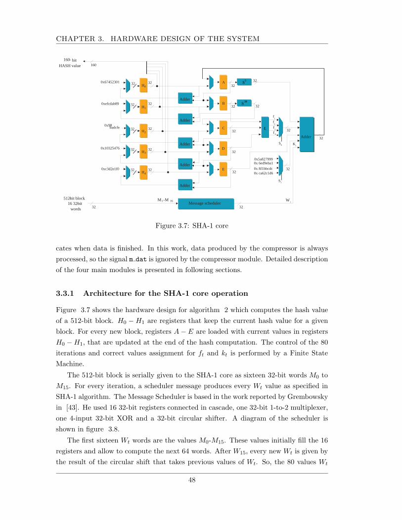
CHAPTER 3. HARDWARE DESIGN OF THE SYSTEM
0x5a827999 0x 6ed9eba1
0x 8f1bbcdc 0x ca62c1d6
A
B
C
D
E
f t
f 1
S 5
Adder
S 30
K t
W t
H 0
H 1
H 2
H 3
H 4
Adder
Adder
Adder
Adder
Adder
S 0
Message scheduler
0x67452301
0xefcdab89
0x98 badcfe
0x10325476
0xc3d2e1f0
32
32
32
32
32
32
32
32
32
32
32
32
32
32
32
32
32
32
32 32
32
32
160 160 - bit
HASH value
512 - bit block 16 32 - bit
words
M 1 - M 16
f 2
f 3
f 4
S 1
Figure 3.7: SHA-1 core
cates when data is finished. In this work, data produced by the compressor is alwaysprocessed, so the signal m dat is ignored by the compressor module. Detailed descriptionof the four main modules is presented in following sections.
3.3.1 Architecture for the SHA-1 core operation
Figure 3.7 shows the hardware design for algorithm 2 which computes the hash valueof a 512-bit block. H0 −H1 are registers that keep the current hash value for a givenblock. For every new block, registers A− E are loaded with current values in registersH0 −H1, that are updated at the end of the hash computation. The control of the 80iterations and correct values assignment for ft and kt is performed by a Finite StateMachine.
The 512-bit block is serially given to the SHA-1 core as sixteen 32-bit words M0 toM15. For every iteration, a scheduler message produces every Wt value as specified inSHA-1 algorithm. The Message Scheduler is based in the work reported by Grembowskyin [43]. He used 16 32-bit registers connected in cascade, one 32-bit 1-to-2 multiplexer,one 4-input 32-bit XOR and a 32-bit circular shifter. A diagram of the scheduler isshown in figure 3.8.
The first sixteen Wt words are the values M0-M15. These values initially fill the 16registers and allow to compute the next 64 words. After W15, every new Wt is given bythe result of the circular shift that takes previous values of Wt. So, the 80 values Wt
48
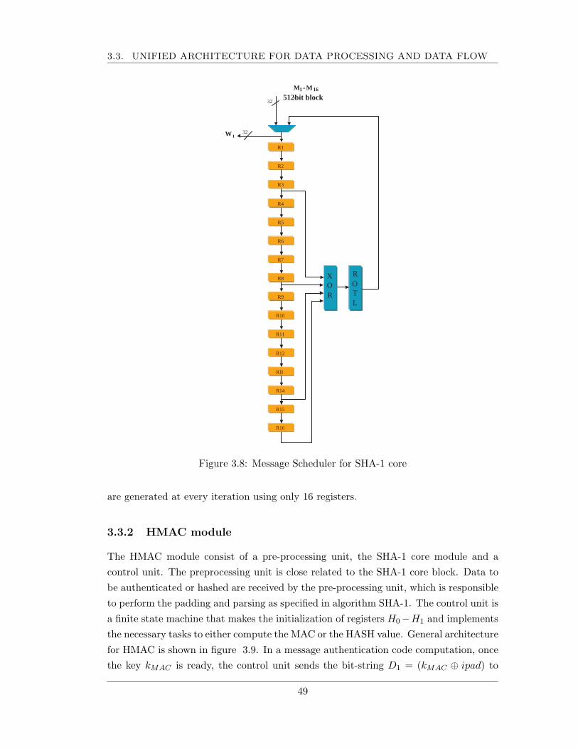
3.3. UNIFIED ARCHITECTURE FOR DATA PROCESSING AND DATA FLOW
R9
R10
R11
R12
32
R 1 3
R14
R15
R16
R1
R2
R3
R4
R5
R6
R7
R8 X O R
R O T L
32
M 1 - M 16
512 - bit block
W t
Figure 3.8: Message Scheduler for SHA-1 core
are generated at every iteration using only 16 registers.
3.3.2 HMAC module
The HMAC module consist of a pre-processing unit, the SHA-1 core module and acontrol unit. The preprocessing unit is close related to the SHA-1 core block. Data tobe authenticated or hashed are received by the pre-processing unit, which is responsibleto perform the padding and parsing as specified in algorithm SHA-1. The control unit isa finite state machine that makes the initialization of registers H0−H1 and implementsthe necessary tasks to either compute the MAC or the HASH value. General architecturefor HMAC is shown in figure 3.9. In a message authentication code computation, oncethe key kMAC is ready, the control unit sends the bit-string D1 = (kMAC ⊕ ipad) to
49
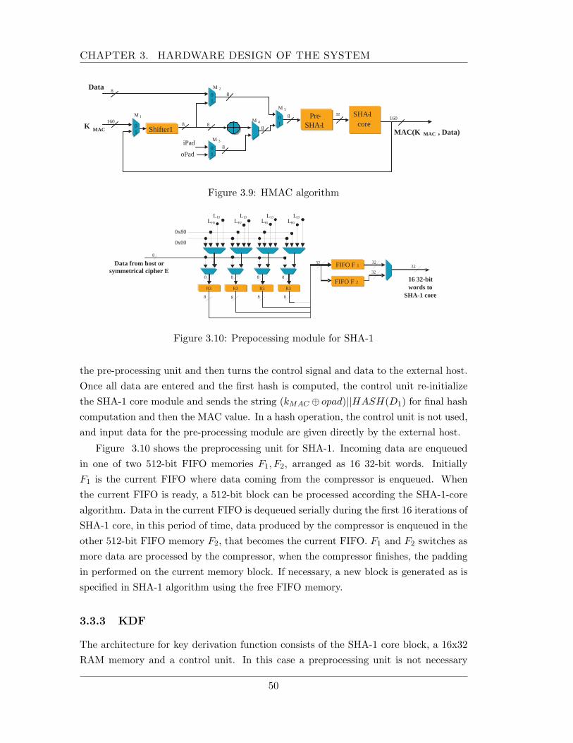
CHAPTER 3. HARDWARE DESIGN OF THE SYSTEM
Shifter 1 K MAC MAC(K MAC , Data) 8
160 160
iPad
oPad
SHA - 1 core
Pre - SHA - 1 8
8
8 8
Data
8
8
0 1
0 1
0 1 0
1
M 4
M 1
M 2
M 3
M 5 32
Figure 3.9: HMAC algorithm
R3 R3 R3 R3
FIFO F 1
0x00
0x80
L H 3 L H 2 L H 1 L H 0
L L 3 L L 3 L L 3 L L 3
Data from host or symmetrical cipher E
8
8 8 8 8
8 8 8 8
32
32
32 32
16 32-bit words to
SHA-1 core
FIFO F 2
Figure 3.10: Prepocessing module for SHA-1
the pre-processing unit and then turns the control signal and data to the external host.Once all data are entered and the first hash is computed, the control unit re-initializethe SHA-1 core module and sends the string (kMAC ⊕ opad)||HASH(D1) for final hashcomputation and then the MAC value. In a hash operation, the control unit is not used,and input data for the pre-processing module are given directly by the external host.
Figure 3.10 shows the preprocessing unit for SHA-1. Incoming data are enqueuedin one of two 512-bit FIFO memories F1, F2, arranged as 16 32-bit words. InitiallyF1 is the current FIFO where data coming from the compressor is enqueued. Whenthe current FIFO is ready, a 512-bit block can be processed according the SHA-1-corealgorithm. Data in the current FIFO is dequeued serially during the first 16 iterations ofSHA-1 core, in this period of time, data produced by the compressor is enqueued in theother 512-bit FIFO memory F2, that becomes the current FIFO. F1 and F2 switches asmore data are processed by the compressor, when the compressor finishes, the paddingin performed on the current memory block. If necessary, a new block is generated as isspecified in SHA-1 algorithm using the free FIFO memory.
3.3.3 KDF
The architecture for key derivation function consists of the SHA-1 core block, a 16x32RAM memory and a control unit. In this case a preprocessing unit is not necessary
50
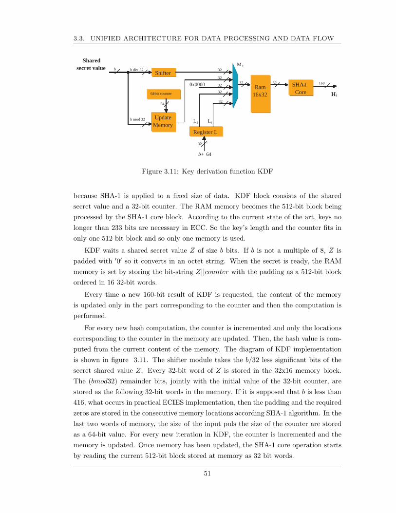
3.3. UNIFIED ARCHITECTURE FOR DATA PROCESSING AND DATA FLOW
Shifter
Shared secret value
H i
32
160
b M t
0x0000
L 1 L 2
Ram 16x32 64 - bit counter
SHA - 1 Core
32 32
Update Memory
32
Register L
b + 64
32
32
32
32
64
b div 32
b mod 32
Figure 3.11: Key derivation function KDF
because SHA-1 is applied to a fixed size of data. KDF block consists of the sharedsecret value and a 32-bit counter. The RAM memory becomes the 512-bit block beingprocessed by the SHA-1 core block. According to the current state of the art, keys nolonger than 233 bits are necessary in ECC. So the key’s length and the counter fits inonly one 512-bit block and so only one memory is used.
KDF waits a shared secret value Z of size b bits. If b is not a multiple of 8, Z ispadded with ′0′ so it converts in an octet string. When the secret is ready, the RAMmemory is set by storing the bit-string Z||counter with the padding as a 512-bit blockordered in 16 32-bit words.
Every time a new 160-bit result of KDF is requested, the content of the memoryis updated only in the part corresponding to the counter and then the computation isperformed.
For every new hash computation, the counter is incremented and only the locationscorresponding to the counter in the memory are updated. Then, the hash value is com-puted from the current content of the memory. The diagram of KDF implementationis shown in figure 3.11. The shifter module takes the b/32 less significant bits of thesecret shared value Z. Every 32-bit word of Z is stored in the 32x16 memory block.The (bmod32) remainder bits, jointly with the initial value of the 32-bit counter, arestored as the following 32-bit words in the memory. If it is supposed that b is less than416, what occurs in practical ECIES implementation, then the padding and the requiredzeros are stored in the consecutive memory locations according SHA-1 algorithm. In thelast two words of memory, the size of the input puls the size of the counter are storedas a 64-bit value. For every new iteration in KDF, the counter is incremented and thememory is updated. Once memory has been updated, the SHA-1 core operation startsby reading the current 512-bit block stored at memory as 32 bit words.
51
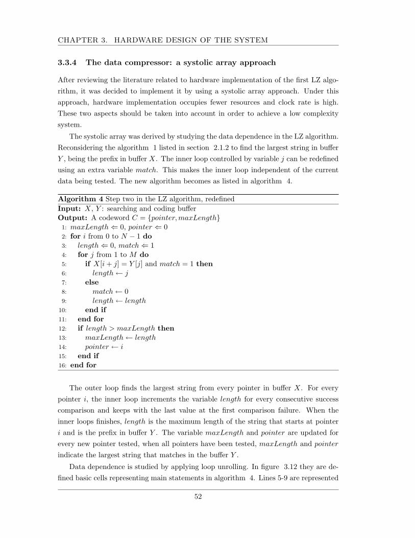
CHAPTER 3. HARDWARE DESIGN OF THE SYSTEM
3.3.4 The data compressor: a systolic array approach
After reviewing the literature related to hardware implementation of the first LZ algo-rithm, it was decided to implement it by using a systolic array approach. Under thisapproach, hardware implementation occupies fewer resources and clock rate is high.These two aspects should be taken into account in order to achieve a low complexitysystem.
The systolic array was derived by studying the data dependence in the LZ algorithm.Reconsidering the algorithm 1 listed in section 2.1.2 to find the largest string in bufferY , being the prefix in buffer X. The inner loop controlled by variable j can be redefinedusing an extra variable match. This makes the inner loop independent of the currentdata being tested. The new algorithm becomes as listed in algorithm 4.
Algorithm 4 Step two in the LZ algorithm, redefinedInput: X, Y : searching and coding bufferOutput: A codeword C = {pointer,maxLength}1: maxLength ⇐ 0, pointer ⇐ 02: for i from 0 to N − 1 do3: length ⇐ 0, match ⇐ 14: for j from 1 to M do5: if X[i + j] = Y [j] and match = 1 then6: length ← j7: else8: match ← 09: length ← length
10: end if11: end for12: if length > maxLength then13: maxLength ← length14: pointer ← i15: end if16: end for
The outer loop finds the largest string from every pointer in buffer X. For everypointer i, the inner loop increments the variable length for every consecutive successcomparison and keeps with the last value at the first comparison failure. When theinner loops finishes, length is the maximum length of the string that starts at pointeri and is the prefix in buffer Y . The variable maxLength and pointer are updated forevery new pointer tested, when all pointers have been tested, maxLength and pointer
indicate the largest string that matches in the buffer Y .
Data dependence is studied by applying loop unrolling. In figure 3.12 they are de-fined basic cells representing main statements in algorithm 4. Lines 5-9 are represented
52
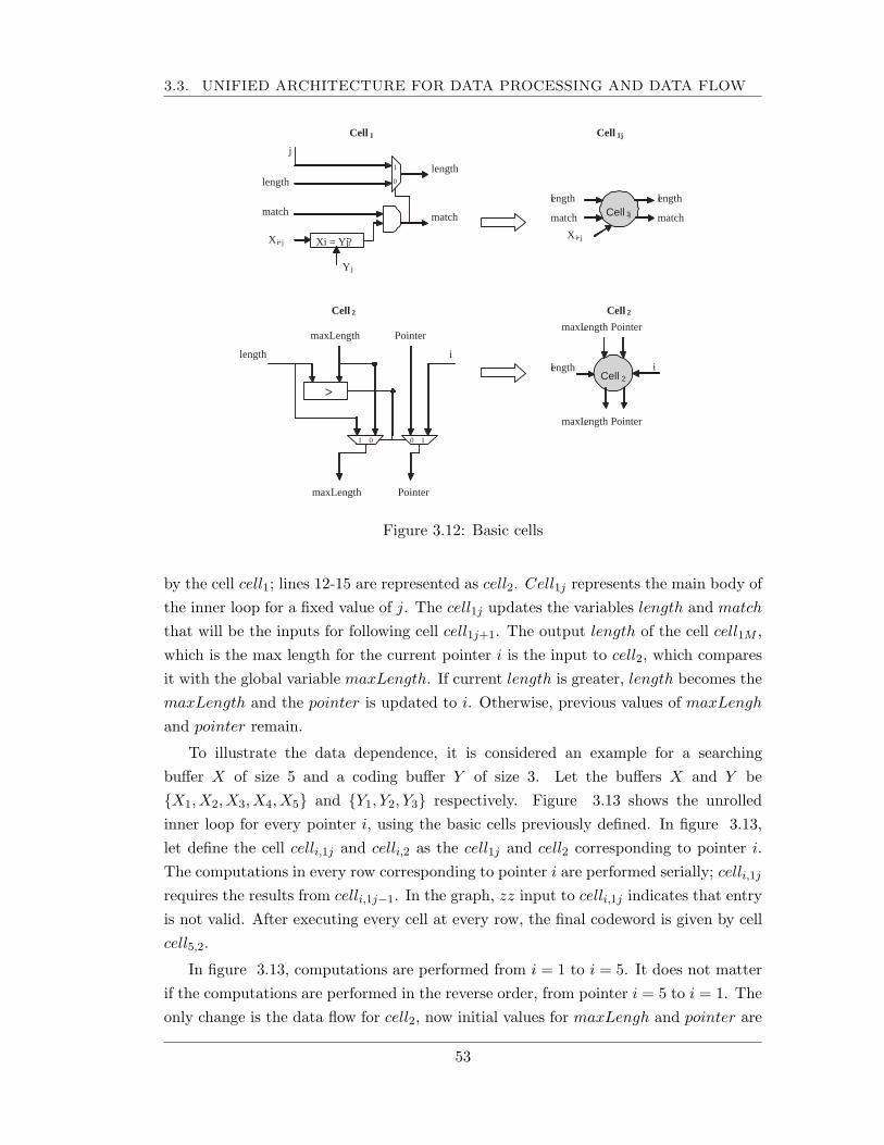
3.3. UNIFIED ARCHITECTURE FOR DATA PROCESSING AND DATA FLOW
l ength
match
l ength
match
l ength
maxL ength Pointer
maxL ength Pointer
Xi = Yj ?
j
match match
length length
X i +j
Y j
Cell 1 j
X i +j
>
Pointer maxLength
length i
Pointer maxLength
1 0 0 1
Cell 1 Cell 1j
Cell 2 Cell 2
Cell 2
i
1
0
Figure 3.12: Basic cells
by the cell cell1; lines 12-15 are represented as cell2. Cell1j represents the main body ofthe inner loop for a fixed value of j. The cell1j updates the variables length and match
that will be the inputs for following cell cell1j+1. The output length of the cell cell1M ,which is the max length for the current pointer i is the input to cell2, which comparesit with the global variable maxLength. If current length is greater, length becomes themaxLength and the pointer is updated to i. Otherwise, previous values of maxLengh
and pointer remain.
To illustrate the data dependence, it is considered an example for a searchingbuffer X of size 5 and a coding buffer Y of size 3. Let the buffers X and Y be{X1, X2, X3, X4, X5} and {Y1, Y2, Y3} respectively. Figure 3.13 shows the unrolledinner loop for every pointer i, using the basic cells previously defined. In figure 3.13,let define the cell celli,1j and celli,2 as the cell1j and cell2 corresponding to pointer i.The computations in every row corresponding to pointer i are performed serially; celli,1j
requires the results from celli,1j−1. In the graph, zz input to celli,1j indicates that entryis not valid. After executing every cell at every row, the final codeword is given by cellcell5,2.
In figure 3.13, computations are performed from i = 1 to i = 5. It does not matterif the computations are performed in the reverse order, from pointer i = 5 to i = 1. Theonly change is the data flow for cell2, now initial values for maxLengh and pointer are
53
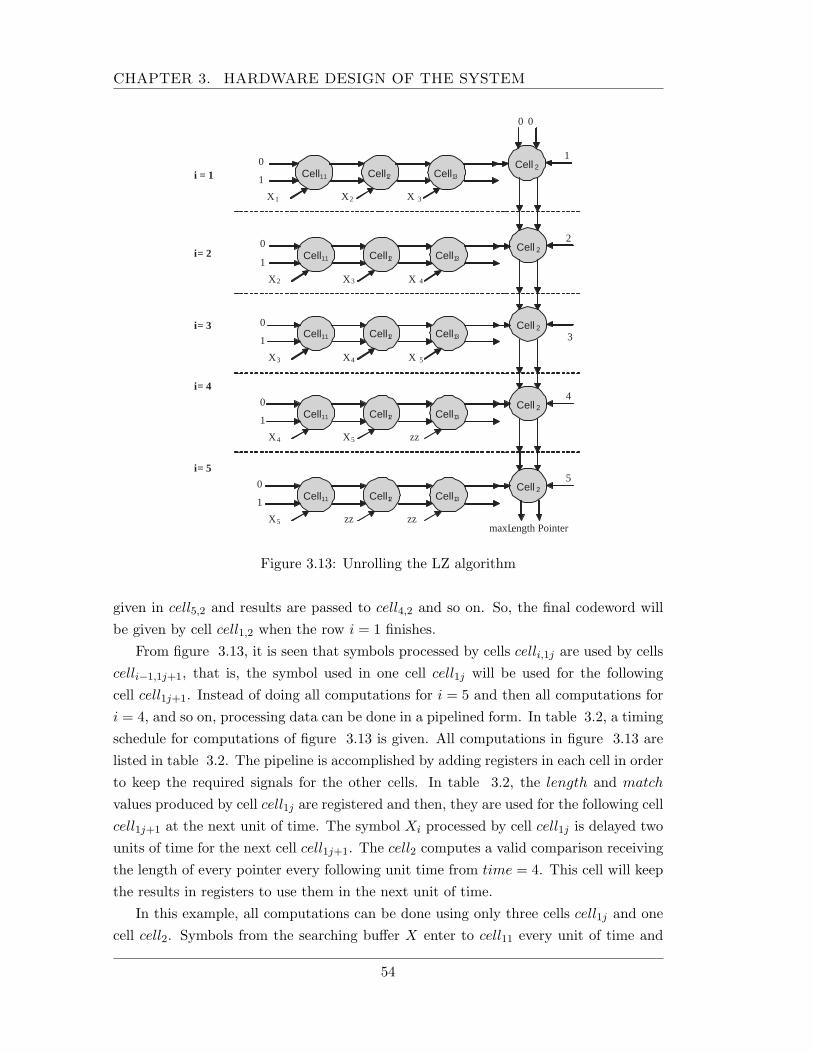
CHAPTER 3. HARDWARE DESIGN OF THE SYSTEM
Cell 11 0
1
X 1
Cell 1 2
Cell 1 3
X 2 X 3
Cell 2
0 0
1
Cell 11 0
1
X 2
Cell 1 2
Cell 1 3
X 3 X 4
Cell 2 2
Cell 11 0
1
X 3
Cell 1 2
Cell 1 3
X 4 X 5
Cell 2 3
Cell 11 0
1
X 4
Cell 1 2
Cell 1 3
X 5 zz
Cell 2 4
Cell 11 0
1
X 5
Cell 1 2
Cell 1 3
zz zz
Cell 2 5
maxL ength Pointer
i = 1
i = 2
i = 3
i = 4
i = 5
Figure 3.13: Unrolling the LZ algorithm
given in cell5,2 and results are passed to cell4,2 and so on. So, the final codeword willbe given by cell cell1,2 when the row i = 1 finishes.
From figure 3.13, it is seen that symbols processed by cells celli,1j are used by cellscelli−1,1j+1, that is, the symbol used in one cell cell1j will be used for the followingcell cell1j+1. Instead of doing all computations for i = 5 and then all computations fori = 4, and so on, processing data can be done in a pipelined form. In table 3.2, a timingschedule for computations of figure 3.13 is given. All computations in figure 3.13 arelisted in table 3.2. The pipeline is accomplished by adding registers in each cell in orderto keep the required signals for the other cells. In table 3.2, the length and match
values produced by cell cell1j are registered and then, they are used for the following cellcell1j+1 at the next unit of time. The symbol Xi processed by cell cell1j is delayed twounits of time for the next cell cell1j+1. The cell2 computes a valid comparison receivingthe length of every pointer every following unit time from time = 4. This cell will keepthe results in registers to use them in the next unit of time.
In this example, all computations can be done using only three cells cell1j and onecell cell2. Symbols from the searching buffer X enter to cell11 every unit of time and
54
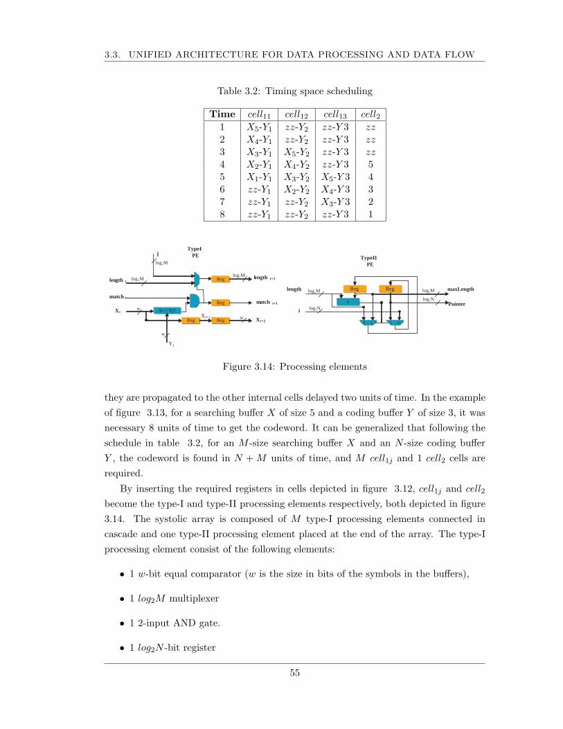
3.3. UNIFIED ARCHITECTURE FOR DATA PROCESSING AND DATA FLOW
Table 3.2: Timing space scheduling
Time cell11 cell12 cell13 cell21 X5-Y1 zz-Y2 zz-Y 3 zz2 X4-Y1 zz-Y2 zz-Y 3 zz3 X3-Y1 X5-Y2 zz-Y 3 zz4 X2-Y1 X4-Y2 zz-Y 3 55 X1-Y1 X3-Y2 X5-Y 3 46 zz-Y1 X2-Y2 X4-Y 3 37 zz-Y1 zz-Y2 X3-Y 3 28 zz-Y1 zz-Y2 zz-Y 3 1
1 0
0 1
>
Reg length
i Pointer
maxLength
Type - II PE
log 2 M
log 2 N
log 2 M
log 2 N
Reg
log 2 M
Xi = Yj?
j
match t m atch t+1
len gth t l ength t+1
X t
Y j
Type - I PE
Reg
Reg
Reg Reg X t+1 X t+2
log 2 M log 2 M
w
w
w
Figure 3.14: Processing elements
they are propagated to the other internal cells delayed two units of time. In the exampleof figure 3.13, for a searching buffer X of size 5 and a coding buffer Y of size 3, it wasnecessary 8 units of time to get the codeword. It can be generalized that following theschedule in table 3.2, for an M -size searching buffer X and an N -size coding bufferY , the codeword is found in N + M units of time, and M cell1j and 1 cell2 cells arerequired.
By inserting the required registers in cells depicted in figure 3.12, cell1j and cell2
become the type-I and type-II processing elements respectively, both depicted in figure3.14. The systolic array is composed of M type-I processing elements connected incascade and one type-II processing element placed at the end of the array. The type-Iprocessing element consist of the following elements:
• 1 w-bit equal comparator (w is the size in bits of the symbols in the buffers),
• 1 log2M multiplexer
• 1 2-input AND gate.
• 1 log2N -bit register
55
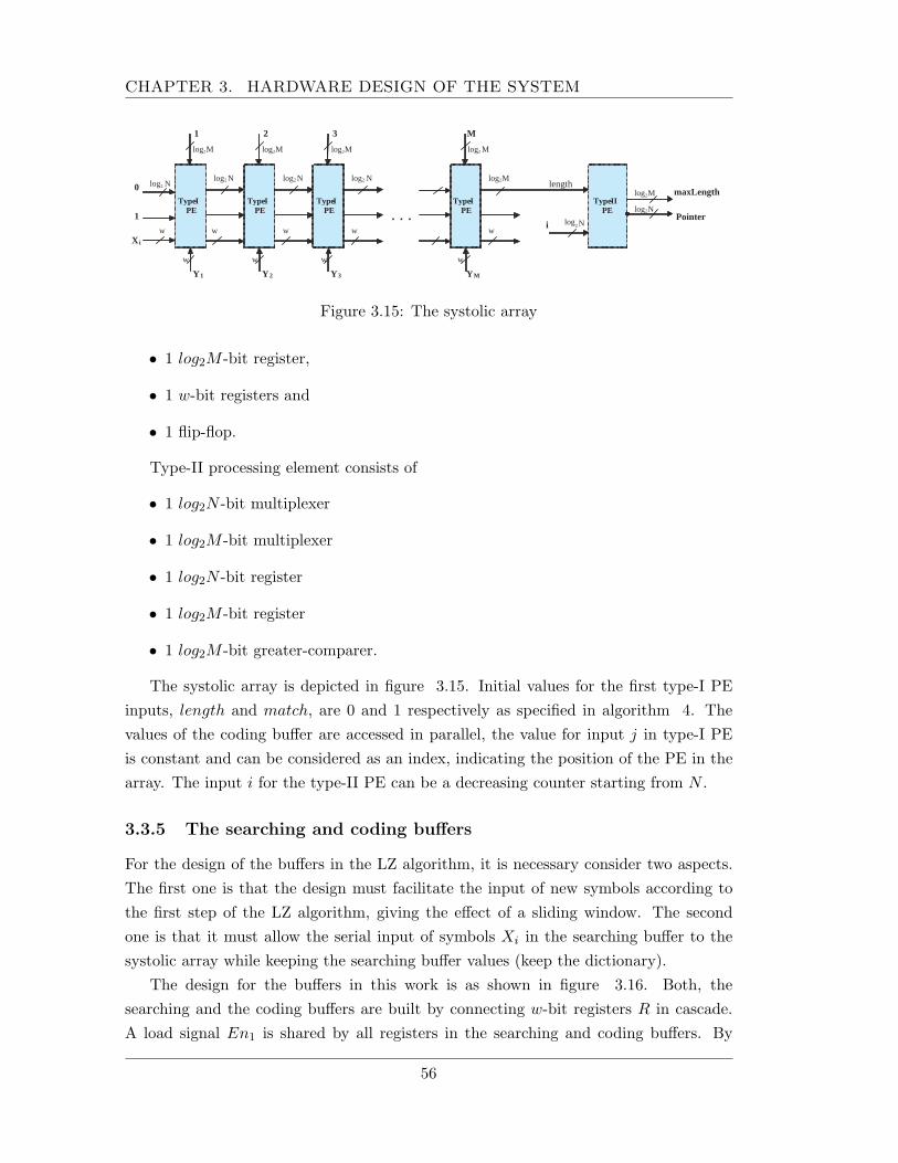
CHAPTER 3. HARDWARE DESIGN OF THE SYSTEM
log 2 M
1
1
0
X i
Y 1
Type - I PE
log 2 N log 2 N
w w
w
log 2 M
2
Y 2
Type - I PE
log 2 N
w
w
log 2 M
3
Y 3
Type - I PE
log 2 N
w
w
. . .
log 2 M
M
Y M
Type - I PE
log 2 M
w
w
i
Type - II PE
log 2 N
log 2 M
log 2 N
length
Pointer
maxLength
Figure 3.15: The systolic array
• 1 log2M -bit register,
• 1 w-bit registers and
• 1 flip-flop.
Type-II processing element consists of
• 1 log2N -bit multiplexer
• 1 log2M -bit multiplexer
• 1 log2N -bit register
• 1 log2M -bit register
• 1 log2M -bit greater-comparer.
The systolic array is depicted in figure 3.15. Initial values for the first type-I PEinputs, length and match, are 0 and 1 respectively as specified in algorithm 4. Thevalues of the coding buffer are accessed in parallel, the value for input j in type-I PEis constant and can be considered as an index, indicating the position of the PE in thearray. The input i for the type-II PE can be a decreasing counter starting from N .
3.3.5 The searching and coding buffers
For the design of the buffers in the LZ algorithm, it is necessary consider two aspects.The first one is that the design must facilitate the input of new symbols according tothe first step of the LZ algorithm, giving the effect of a sliding window. The secondone is that it must allow the serial input of symbols Xi in the searching buffer to thesystolic array while keeping the searching buffer values (keep the dictionary).
The design for the buffers in this work is as shown in figure 3.16. Both, thesearching and the coding buffers are built by connecting w-bit registers R in cascade.A load signal En1 is shared by all registers in the searching and coding buffers. By
56
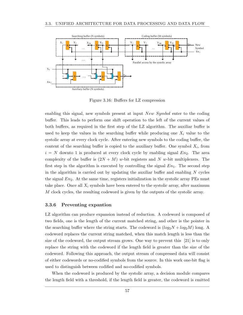
3.3. UNIFIED ARCHITECTURE FOR DATA PROCESSING AND DATA FLOW
New Symbol En 1
…
Y 1 Y M - 1 Y M Y 2
Coding buffer (M symbols)
Parallel access by the systolic array
w R R R
S 0 En 2
…
R …
X 1 X N - 1 X N X 2
Searchin g buffer (N symbols)
0
…
w
Auxiliary buffer (N symbols)
R R
R R R
Figure 3.16: Buffers for LZ compression
enabling this signal, new symbols present at input New Symbol enter to the codingbuffer. This leads to perform one shift operation to the left of the current values ofboth buffers, as required in the first step of the LZ algorithm. The auxiliar buffer isused to keep the values in the searching buffer while producing one Xi value to thesystolic array at every clock cycle. After entering new symbols to the coding buffer, thecontent of the searching buffer is copied to the auxiliary buffer. One symbol Xi, fromi = N downto 1 is produced at every clock cycle by enabling signal En2. The areacomplexity of the buffer is (2N + M) w-bit registers and N w-bit multiplexers. Thefirst step in the algorithm is executed by controlling the signal En1. The second stepin the algorithm is carried out by updating the auxiliar buffer and enabling N cyclesthe signal En2. At the same time, registers initialization in the systolic array PEs musttake place. Once all Xi symbols have been entered to the systolic array, after maximumM clock cycles, the resulting codeword is given by the outputs of the systolic array.
3.3.6 Preventing expantion
LZ algorithm can produce expansion instead of reduction. A codeword is composed oftwo fields, one is the length of the current matched string, and other is the pointer inthe searching buffer where the string starts. The codeword is (log2N + log2M) long. Acodeword replaces the current string matched, when this match length is less than thesize of the codeword, the output stream grows. One way to prevent this [21] is to onlyreplace the string with the codeword if the length field is greater than the size of thecodeword. Following this approach, the output stream of compressed data will consistof either codewords or no-codified symbols from the source. In this work one-bit flag isused to distinguish between codified and no-codified symbols.
When the codeword is produced by the systolic array, a decision module comparesthe length field with a threshold, if the length field is greater, the codeword is emitted
57
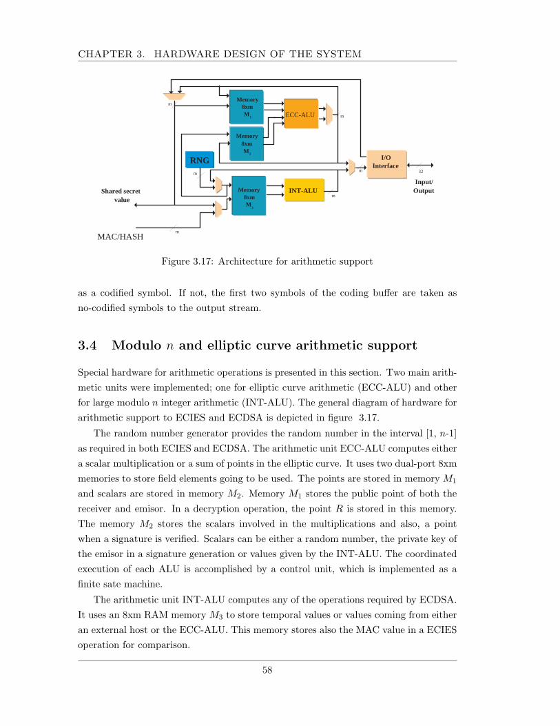
CHAPTER 3. HARDWARE DESIGN OF THE SYSTEM
ECC-ALU
INT-ALU
Memory 8xm M 1
I/O Interface
RNG
m
m
m
m
m
32
Shared secret value
Input/ Output
MAC/HASH
m
Memory 8xm M 2
Memory 8xm M
3
Figure 3.17: Architecture for arithmetic support
as a codified symbol. If not, the first two symbols of the coding buffer are taken asno-codified symbols to the output stream.
3.4 Modulo n and elliptic curve arithmetic support
Special hardware for arithmetic operations is presented in this section. Two main arith-metic units were implemented; one for elliptic curve arithmetic (ECC-ALU) and otherfor large modulo n integer arithmetic (INT-ALU). The general diagram of hardware forarithmetic support to ECIES and ECDSA is depicted in figure 3.17.
The random number generator provides the random number in the interval [1, n-1]as required in both ECIES and ECDSA. The arithmetic unit ECC-ALU computes eithera scalar multiplication or a sum of points in the elliptic curve. It uses two dual-port 8xmmemories to store field elements going to be used. The points are stored in memory M1
and scalars are stored in memory M2. Memory M1 stores the public point of both thereceiver and emisor. In a decryption operation, the point R is stored in this memory.The memory M2 stores the scalars involved in the multiplications and also, a pointwhen a signature is verified. Scalars can be either a random number, the private key ofthe emisor in a signature generation or values given by the INT-ALU. The coordinatedexecution of each ALU is accomplished by a control unit, which is implemented as afinite sate machine.
The arithmetic unit INT-ALU computes any of the operations required by ECDSA.It uses an 8xm RAM memory M3 to store temporal values or values coming from eitheran external host or the ECC-ALU. This memory stores also the MAC value in a ECIESoperation for comparison.
58
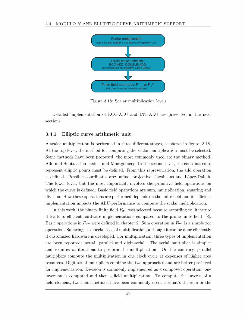
3.4. MODULO N AND ELLIPTIC CURVE ARITHMETIC SUPPORT
Scalar multiplication (add & double, addition & sub chains, Montgomery, 2P)
Elliptic curve arithmetic: ECC-ADD, DOUBLE-ADD
(coordinates affine, projective, López-Dahab)
Finite field arithmetic: F p or F 2 m
(Add, multiplication, inversion, square)
Figure 3.18: Scalar multiplication levels
Detailed implementation of ECC-ALU and INT-ALU are presented in the nextsections.
3.4.1 Elliptic curve arithmetic unit
A scalar multiplication is performed in three different stages, as shown in figure 3.18.At the top level, the method for computing the scalar multiplication must be selected.Some methods have been proposed, the most commonly used are the binary method,Add and Subtraction chains, and Montgomery. In the second level, the coordinates torepresent elliptic points must be defined. From this representation, the add operationis defined. Possible coordinates are: affine, projective, Jacobeans and Lopez-Dahab.The lower level, but the most important, involves the primitive field operations onwhich the curve is defined. Basic field operations are sum, multiplication, squaring anddivision. How these operations are performed depends on the finite field and its efficientimplementation impacts the ALU performance to compute the scalar multiplication.
In this work, the binary finite field F2m was selected because according to literatureit leads to efficient hardware implementations compared to the prime finite field [8].Basic operations in F2m were defined in chapter 2. Sum operation in F2m is a simple xoroperation. Squaring is a special case of multiplication, although it can be done efficientlyif customized hardware is developed. For multiplication, three types of implementationare been reported: serial, parallel and digit-serial. The serial multiplier is simplerand requires m iterations to perform the multiplication. On the contrary, parallelmultipliers compute the multiplication in one clock cycle at expenses of higher arearesources. Digit-serial multipliers combine the two approaches and are better preferredfor implementation. Division is commonly implemented as a composed operation: oneinversion is computed and then a field multiplication. To compute the inverse of afield element, two main methods have been commonly used: Fermat’s theorem or the
59
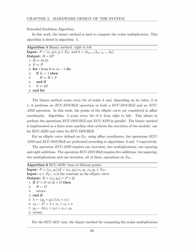
CHAPTER 3. HARDWARE DESIGN OF THE SYSTEM
Extended Euclidean Algorithm.In this work, the binary method is used to compute the scalar multiplication. This
algorithm is listed in algorithm 5.
Algorithm 5 Binary method: right to leftInput: P = (x, y)x, y ∈ F2m and k = (km−1, km−2, ..., k0)Output: R = kP1: R ⇐ (0, 0)2: S ⇐ P3: for i from 0 to m− 1 do4: if ki = 1 then5: R ⇐ R + S6: end if7: S ⇐ 2S8: end for
The binary method scans every bit of scalar k and, depending on its value, 0 or1, it performs an ECC-DOUBLE operation or both a ECC-DOUBLE and an ECC-ADD operation. In this work, the points of the elliptic curve are considered in affinecoordinates. Algorithm 5 scans every bit of k from right to left. This allows toperform the operations ECC-DOUBLE and ECC-ADD in parallel. The binary methodis implemented as a finite state machine that orchests the execution of two module: onefor ECC-ADD and other for ECC-DOUBLE.
For an elliptic curve defined on F2m using affine coordinates, the operations ECC-ADD and ECC-DOUBLE are performed according to algorithms 6 and 7 respectively.
The operation ECC-ADD requires one inversion, two multiplications, one squaringand eight additions. The operation ECC-DOUBLE requires five additions, two squaring,two multiplications and one inversion, all of them, operations on F2m .
Algorithm 6 ECC-ADD: Sum of diferent pointsInput: P = (x1, y1),Q = (x2, y2),x1, y1, x2, y2 ∈ F2m
Input: a ∈ F2m , a is the constant in the elliptic curveOutput: R = (x3, y3) = P + Q1: if P = O or Q = O then2: R ← O3: return4: end if5: λ ← (y2 + y1)/(x2 + x1)6: x3 ← λ2 + λ + x1 + x2 + a7: y3 ← λ(x1 + x3) + x3 + y1
8: return
For the ECC-ALU unit, the binary method for computing the scalar multiplication
60
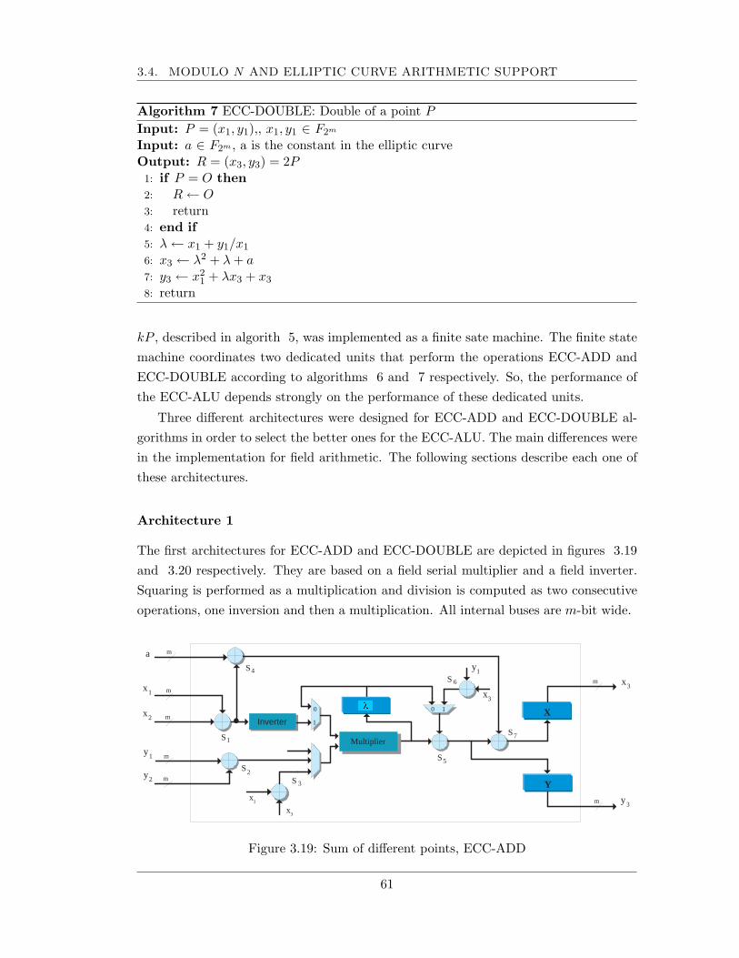
3.4. MODULO N AND ELLIPTIC CURVE ARITHMETIC SUPPORT
Algorithm 7 ECC-DOUBLE: Double of a point P
Input: P = (x1, y1),, x1, y1 ∈ F2m
Input: a ∈ F2m , a is the constant in the elliptic curveOutput: R = (x3, y3) = 2P1: if P = O then2: R ← O3: return4: end if5: λ ← x1 + y1/x1
6: x3 ← λ2 + λ + a7: y3 ← x2
1 + λx3 + x3
8: return
kP , described in algorith 5, was implemented as a finite sate machine. The finite statemachine coordinates two dedicated units that perform the operations ECC-ADD andECC-DOUBLE according to algorithms 6 and 7 respectively. So, the performance ofthe ECC-ALU depends strongly on the performance of these dedicated units.
Three different architectures were designed for ECC-ADD and ECC-DOUBLE al-gorithms in order to select the better ones for the ECC-ALU. The main differences werein the implementation for field arithmetic. The following sections describe each one ofthese architectures.
Architecture 1
The first architectures for ECC-ADD and ECC-DOUBLE are depicted in figures 3.19and 3.20 respectively. They are based on a field serial multiplier and a field inverter.Squaring is performed as a multiplication and division is computed as two consecutiveoperations, one inversion and then a multiplication. All internal buses are m-bit wide.
x 1
Y
X
S 2 S 3
m
m
m
Inverter
0
1
S 1 Multiplier
0 1
m
S 4
S 5
S 6
S 7
x 2
y 1
y 2 m
m
m a
x 1
x 3
y 1
x 3
x 3
y 3
?
Figure 3.19: Sum of different points, ECC-ADD
61
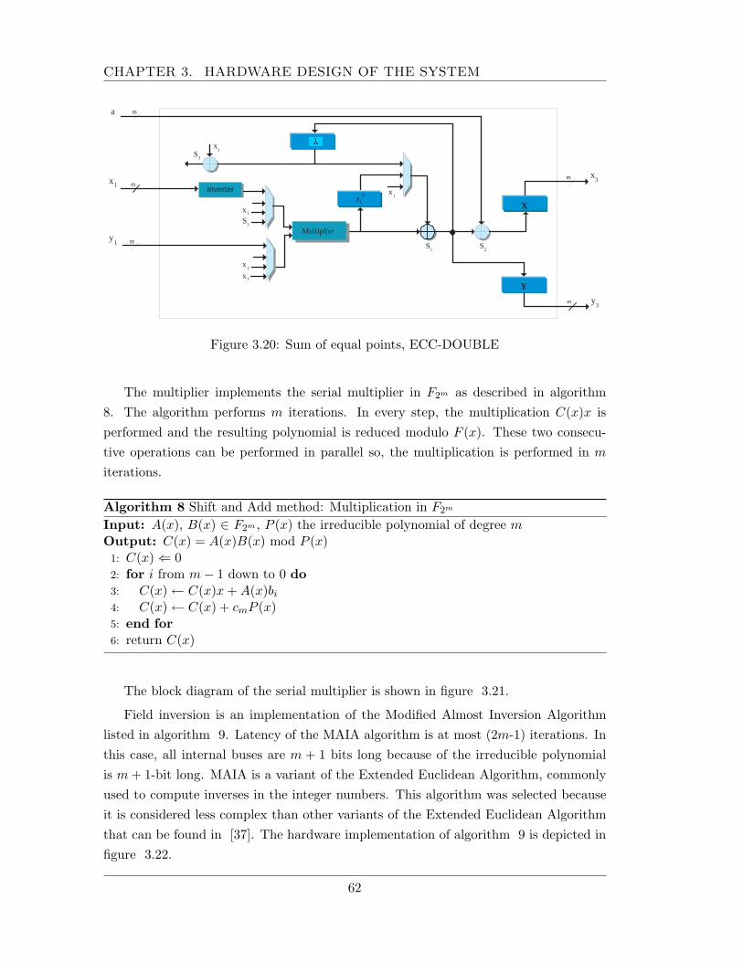
CHAPTER 3. HARDWARE DESIGN OF THE SYSTEM
x 1
Y
X
m
m
Inverter
S 1
Multiplier
2
1 x
m
S 3
y 1 m
m a
x 3
x 3
y 3
S 3
x 1
x
1
x 1
x 1
S 2
Figure 3.20: Sum of equal points, ECC-DOUBLE
The multiplier implements the serial multiplier in F2m as described in algorithm8. The algorithm performs m iterations. In every step, the multiplication C(x)x isperformed and the resulting polynomial is reduced modulo F (x). These two consecu-tive operations can be performed in parallel so, the multiplication is performed in m
iterations.
Algorithm 8 Shift and Add method: Multiplication in F2m
Input: A(x), B(x) ∈ F2m , P (x) the irreducible polynomial of degree mOutput: C(x) = A(x)B(x) mod P (x)1: C(x) ⇐ 02: for i from m− 1 down to 0 do3: C(x) ← C(x)x + A(x)bi
4: C(x) ← C(x) + cmP (x)5: end for6: return C(x)
The block diagram of the serial multiplier is shown in figure 3.21.
Field inversion is an implementation of the Modified Almost Inversion Algorithmlisted in algorithm 9. Latency of the MAIA algorithm is at most (2m-1) iterations. Inthis case, all internal buses are m + 1 bits long because of the irreducible polynomialis m + 1-bit long. MAIA is a variant of the Extended Euclidean Algorithm, commonlyused to compute inverses in the integer numbers. This algorithm was selected becauseit is considered less complex than other variants of the Extended Euclidean Algorithmthat can be found in [37]. The hardware implementation of algorithm 9 is depicted infigure 3.22.
62
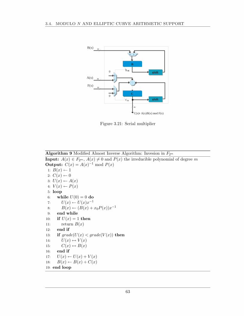
3.4. MODULO N AND ELLIPTIC CURVE ARITHMETIC SUPPORT
C(x) = A(x)· B(x) m od F(x)
A(x)
shift
B
shift
C
B(x)
F(x)
0
0 0
1
1
0
c m
b m - 1
0 1
m
m
m
m
Figure 3.21: Serial multiplier
Algorithm 9 Modified Almost Inverse Algorithm: Invesion in F2m
Input: A(x) ∈ F2m , A(x) 6= 0 and P (x) the irreducible polynomial of degree mOutput: C(x) = A(x)−1 mod P (x)1: B(x) ← 12: C(x) ← 03: U(x) ← A(x)4: V (x) ← P (x)5: loop6: while U(0) = 0 do7: U(x) ← U(x)x−1
8: B(x) ← (B(x) + x0P (x))x−1
9: end while10: if U(x) = 1 then11: return B(x)12: end if13: if grade(U(x) < grade(V (x)) then14: U(x) ↔ V (x)15: C(x) ↔ B(x)16: end if17: U(x) ← U(x) + V (x)18: B(x) ← B(x) + C(x)19: end loop
63
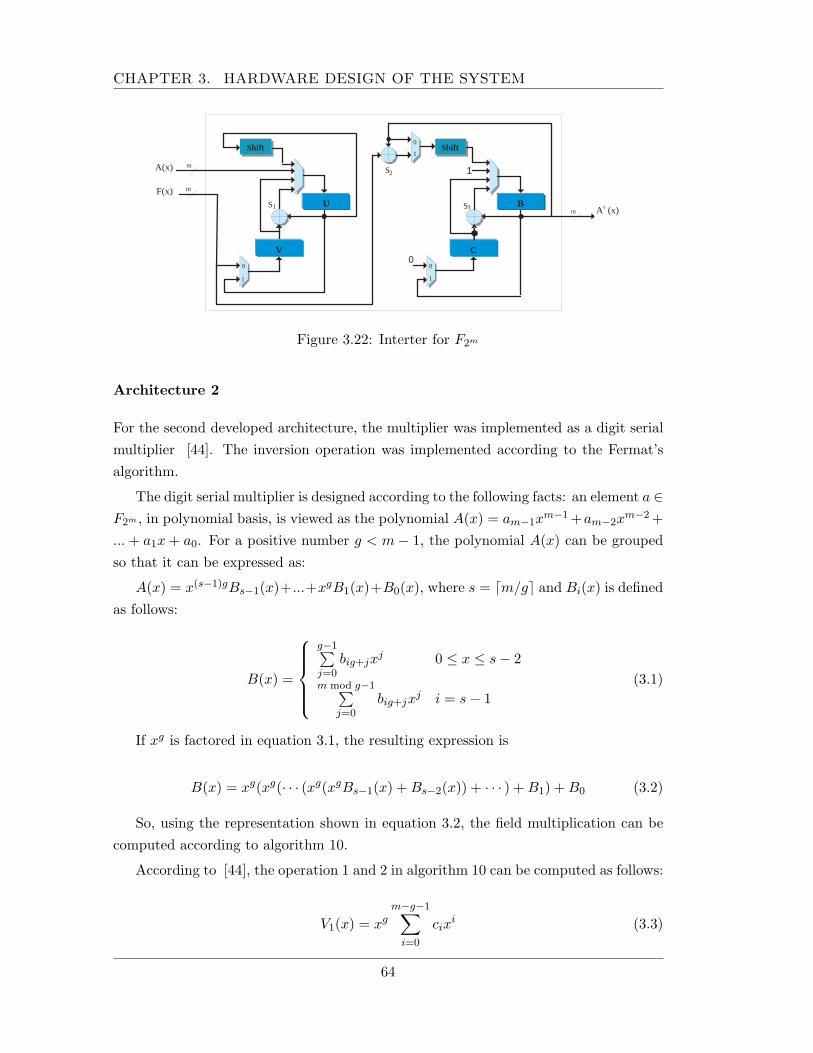
CHAPTER 3. HARDWARE DESIGN OF THE SYSTEM
0
A(x)
F(x)
A - 1 (x)
1
B
Shift 0
1
C
S 1 U
Shift
0
1
V
S 2
S 3
0
1
m
m
m
Figure 3.22: Interter for F2m
Architecture 2
For the second developed architecture, the multiplier was implemented as a digit serialmultiplier [44]. The inversion operation was implemented according to the Fermat’salgorithm.
The digit serial multiplier is designed according to the following facts: an element a ∈F2m , in polynomial basis, is viewed as the polynomial A(x) = am−1x
m−1 +am−2xm−2 +
... + a1x + a0. For a positive number g < m− 1, the polynomial A(x) can be groupedso that it can be expressed as:
A(x) = x(s−1)gBs−1(x)+...+xgB1(x)+B0(x), where s = dm/ge and Bi(x) is definedas follows:
B(x) =
g−1∑j=0
big+jxj 0 ≤ x ≤ s− 2
m mod g−1∑j=0
big+jxj i = s− 1
(3.1)
If xg is factored in equation 3.1, the resulting expression is
B(x) = xg(xg(· · · (xg(xgBs−1(x) + Bs−2(x)) + · · · ) + B1) + B0 (3.2)
So, using the representation shown in equation 3.2, the field multiplication can becomputed according to algorithm 10.
According to [44], the operation 1 and 2 in algorithm 10 can be computed as follows:
V1(x) = xgm−g−1∑
i=0
cixi (3.3)
64
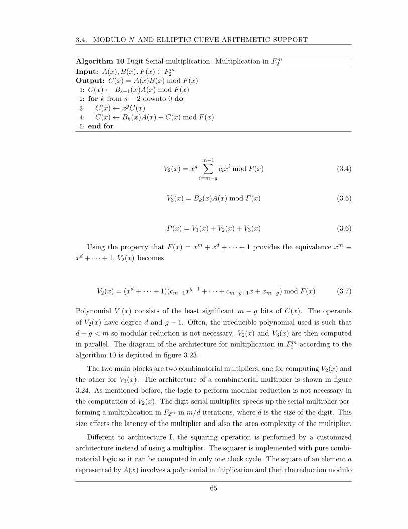
3.4. MODULO N AND ELLIPTIC CURVE ARITHMETIC SUPPORT
Algorithm 10 Digit-Serial multiplication: Multiplication in Fm2
Input: A(x), B(x), F (x) ∈ Fm2
Output: C(x) = A(x)B(x) mod F (x)1: C(x) ← Bs−1(x)A(x) mod F (x)2: for k from s− 2 downto 0 do3: C(x) ← xgC(x)4: C(x) ← Bk(x)A(x) + C(x) mod F (x)5: end for
V2(x) = xgm−1∑
i=m−g
cixi mod F (x) (3.4)
V3(x) = Bk(x)A(x) mod F (x) (3.5)
P (x) = V1(x) + V2(x) + V3(x) (3.6)
Using the property that F (x) = xm + xd + · · · + 1 provides the equivalence xm ≡xd + · · ·+ 1, V2(x) becomes
V2(x) = (xd + · · ·+ 1)(cm−1xg−1 + · · ·+ cm−g+1x + xm−g) mod F (x) (3.7)
Polynomial V1(x) consists of the least significant m − g bits of C(x). The operandsof V2(x) have degree d and g − 1. Often, the irreducible polynomial used is such thatd + g < m so modular reduction is not necessary. V2(x) and V3(x) are then computedin parallel. The diagram of the architecture for multiplication in Fm
2 according to thealgorithm 10 is depicted in figure 3.23.
The two main blocks are two combinatorial multipliers, one for computing V2(x) andthe other for V3(x). The architecture of a combinatorial multiplier is shown in figure3.24. As mentioned before, the logic to perform modular reduction is not necessary inthe computation of V2(x). The digit-serial multiplier speeds-up the serial multiplier per-forming a multiplication in F2m in m/d iterations, where d is the size of the digit. Thissize affects the latency of the multiplier and also the area complexity of the multiplier.
Different to architecture I, the squaring operation is performed by a customizedarchitecture instead of using a multiplier. The squarer is implemented with pure combi-natorial logic so it can be computed in only one clock cycle. The square of an element a
represented by A(x) involves a polynomial multiplication and then the reduction modulo
65
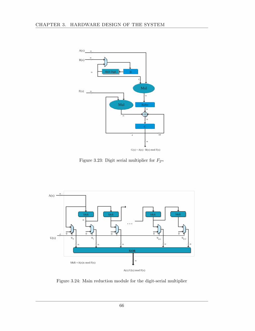
CHAPTER 3. HARDWARE DESIGN OF THE SYSTEM
Buffer
Mul
Mul
C(x) = A(x) · B(x) mod F(x)
A(x)
B(x)
B
0
1
m
d
m
m
d m - d
Shift Digit
C
m
F(x)
m
m
m
m
m
Figure 3.23: Digit serial multiplier for F2m
0 0
A(x) U(x) mod F(x)
S&R S&R S&R S&R
XOR
u 0 u d-2
0 0 0
· · ·
A(x)
U(x)
m
d
m
m
m S&R = A(x)x mod F(x)
u d-1
u 1
m m m m
Figure 3.24: Main reduction module for the digit-serial multiplier
66
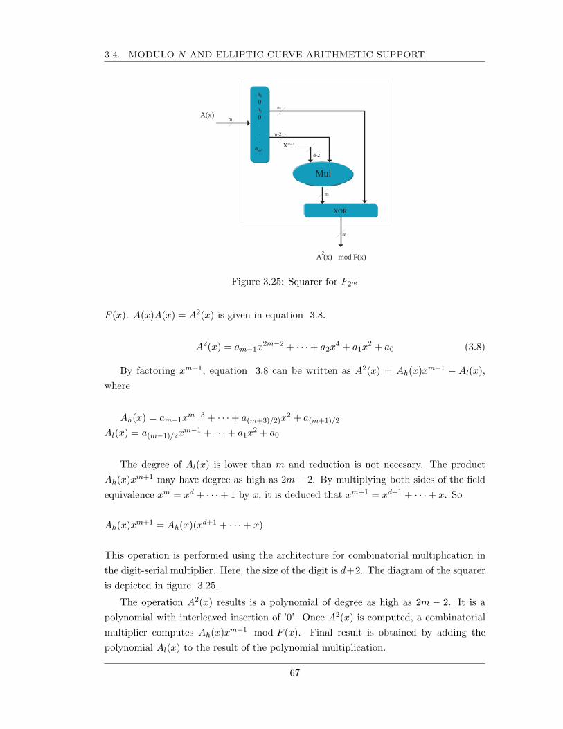
3.4. MODULO N AND ELLIPTIC CURVE ARITHMETIC SUPPORT
A(x)
X m+1
m
A (x) 2
mod F(x)
m
m-2
Mul
a 0
0 a 1
0 . . .
a m - 1
XOR
d +2
m
m
Figure 3.25: Squarer for F2m
F (x). A(x)A(x) = A2(x) is given in equation 3.8.
A2(x) = am−1x2m−2 + · · ·+ a2x
4 + a1x2 + a0 (3.8)
By factoring xm+1, equation 3.8 can be written as A2(x) = Ah(x)xm+1 + Al(x),where
Ah(x) = am−1xm−3 + · · ·+ a(m+3)/2)x
2 + a(m+1)/2
Al(x) = a(m−1)/2xm−1 + · · ·+ a1x
2 + a0
The degree of Al(x) is lower than m and reduction is not necesary. The productAh(x)xm+1 may have degree as high as 2m− 2. By multiplying both sides of the fieldequivalence xm = xd + · · ·+ 1 by x, it is deduced that xm+1 = xd+1 + · · ·+ x. So
Ah(x)xm+1 = Ah(x)(xd+1 + · · ·+ x)
This operation is performed using the architecture for combinatorial multiplication inthe digit-serial multiplier. Here, the size of the digit is d+2. The diagram of the squareris depicted in figure 3.25.
The operation A2(x) results is a polynomial of degree as high as 2m − 2. It is apolynomial with interleaved insertion of ’0’. Once A2(x) is computed, a combinatorialmultiplier computes Ah(x)xm+1 mod F (x). Final result is obtained by adding thepolynomial Al(x) to the result of the polynomial multiplication.
67
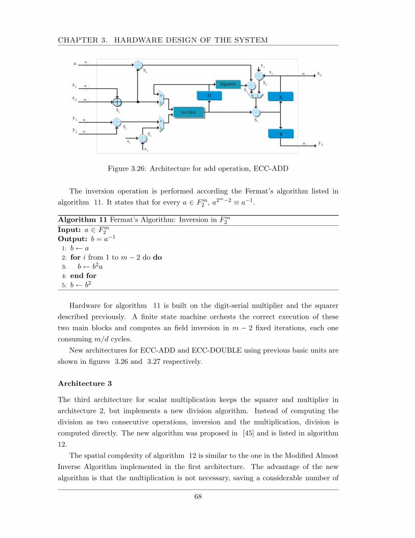
CHAPTER 3. HARDWARE DESIGN OF THE SYSTEM
x 1
Y
X
S 2
S 3
m
m
m
Squarer
0
1
S 1 Inv/Mul
0 1
m S
4
S 5
S 6
S 7
x 2
y 1
y 2 m
m
m a
x 1
x 3
y 1
x 3 x 3
y 3
0
1
R
Figure 3.26: Architecture for add operation, ECC-ADD
The inversion operation is performed according the Fermat’s algorithm listed inalgorithm 11. It states that for every a ∈ Fm
2 , a2m−2 ≡ a−1.
Algorithm 11 Fermat’s Algorithm: Inversion in Fm2
Input: a ∈ Fm2
Output: b = a−1
1: b ← a2: for i from 1 to m− 2 do do3: b ← b2a4: end for5: b ← b2
Hardware for algorithm 11 is built on the digit-serial multiplier and the squarerdescribed previously. A finite state machine orchests the correct execution of thesetwo main blocks and computes an field inversion in m − 2 fixed iterations, each oneconsuming m/d cycles.
New architectures for ECC-ADD and ECC-DOUBLE using previous basic units areshown in figures 3.26 and 3.27 respectively.
Architecture 3
The third architecture for scalar multiplication keeps the squarer and multiplier inarchitecture 2, but implements a new division algorithm. Instead of computing thedivision as two consecutive operations, inversion and the multiplication, division iscomputed directly. The new algorithm was proposed in [45] and is listed in algorithm12.
The spatial complexity of algorithm 12 is similar to the one in the Modified AlmostInverse Algorithm implemented in the first architecture. The advantage of the newalgorithm is that the multiplication is not necessary, saving a considerable number of
68
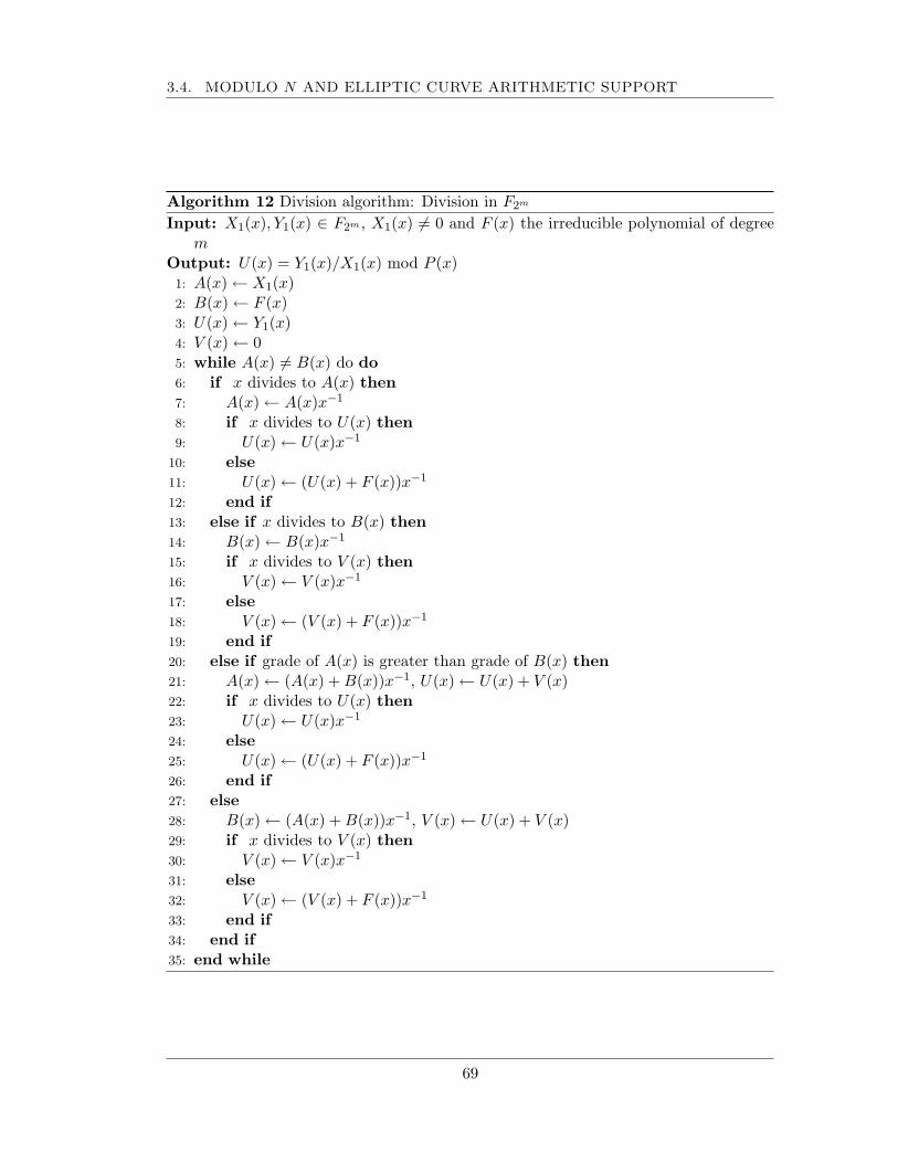
3.4. MODULO N AND ELLIPTIC CURVE ARITHMETIC SUPPORT
Algorithm 12 Division algorithm: Division in F2m
Input: X1(x), Y1(x) ∈ F2m , X1(x) 6= 0 and F (x) the irreducible polynomial of degreem
Output: U(x) = Y1(x)/X1(x) mod P (x)1: A(x) ← X1(x)2: B(x) ← F (x)3: U(x) ← Y1(x)4: V (x) ← 05: while A(x) 6= B(x) do do6: if x divides to A(x) then7: A(x) ← A(x)x−1
8: if x divides to U(x) then9: U(x) ← U(x)x−1
10: else11: U(x) ← (U(x) + F (x))x−1
12: end if13: else if x divides to B(x) then14: B(x) ← B(x)x−1
15: if x divides to V (x) then16: V (x) ← V (x)x−1
17: else18: V (x) ← (V (x) + F (x))x−1
19: end if20: else if grade of A(x) is greater than grade of B(x) then21: A(x) ← (A(x) + B(x))x−1, U(x) ← U(x) + V (x)22: if x divides to U(x) then23: U(x) ← U(x)x−1
24: else25: U(x) ← (U(x) + F (x))x−1
26: end if27: else28: B(x) ← (A(x) + B(x))x−1, V (x) ← U(x) + V (x)29: if x divides to V (x) then30: V (x) ← V (x)x−1
31: else32: V (x) ← (V (x) + F (x))x−1
33: end if34: end if35: end while
69
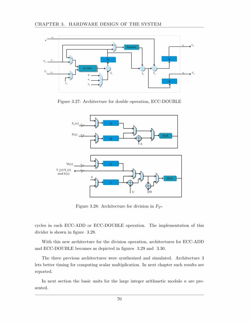
CHAPTER 3. HARDWARE DESIGN OF THE SYSTEM
x 1
Y
X
S 1
m
m m
Squarer
0
1
Inv/Mul
m
S 2
S 3
y 1
m
a
x 3
x 3
y 3 0
1
R
0
1
x 3
x 1
0
Figure 3.27: Architecture for double operation, ECC-DOUBLE
A
0
X 1 (x)
F(x)
A m
U m
B Shift
Shift V
U M
Y 1(x)
m Y 1 (x)/X
1 (x)
mod F(x)
m
Figure 3.28: Architecture for division in F2m
cycles in each ECC-ADD or ECC-DOUBLE operation. The implementation of thisdivider is shown in figure 3.28.
With this new architecture for the division operation, architectures for ECC-ADDand ECC-DOUBLE becomes as depicted in figures 3.29 and 3.30.
The three previous architectures were synthesized and simulated. Architecture 3lets better timing for computing scalar multiplication. In next chapter such results arereported.
In next section the basic units for the large integer arithmetic modulo n are pre-sented.
70
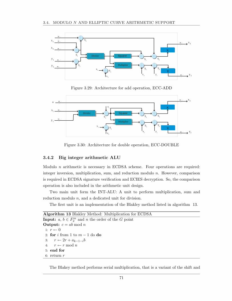
3.4. MODULO N AND ELLIPTIC CURVE ARITHMETIC SUPPORT
Y
X
S 7
m
Squarer
Multiplier
m
S 5
x 3
x 3
y 3
x 1 S
3
Divider
x 3
y 1
S 6
S 8
x 1
S 2
m
m
S 1
x 2
y 1
y 2 m
m
m
S 4
Figure 3.29: Architecture for add operation, ECC-ADD
x 1
Y
X
S 5
m
m
m
Squarer
Multiplier
m
S 3
y 1
m a
x 3
x 3
y 3
x 1
x 1
S 2
S 1
Divider
x 3
y 1
S 4
S 6
Figure 3.30: Architecture for double operation, ECC-DOUBLE
3.4.2 Big integer arithmetic ALU
Modulo n arithmetic is necessary in ECDSA scheme. Four operations are required:integer inversion, multiplication, sum, and reduction modulo n. However, comparisonis required in ECDSA signature verification and ECIES decryption. So, the comparisonoperation is also included in the arithmetic unit design.
Two main unit form the INT-ALU: A unit to perform multiplication, sum andreduction modulo n, and a dedicated unit for division.
The first unit is an implementation of the Blakley method listed in algorithm 13.
Algorithm 13 Blakley Method: Multiplication for ECDSAInput: a, b ∈ Fm
2 and n the order of the G pointOutput: c = ab mod n1: r ← 02: for i from 1 to m− 1 do do3: r ← 2r + ak−1−ib4: r ← r mod n5: end for6: return r
The Blakey method performs serial multiplication, that is a variant of the shift and
71
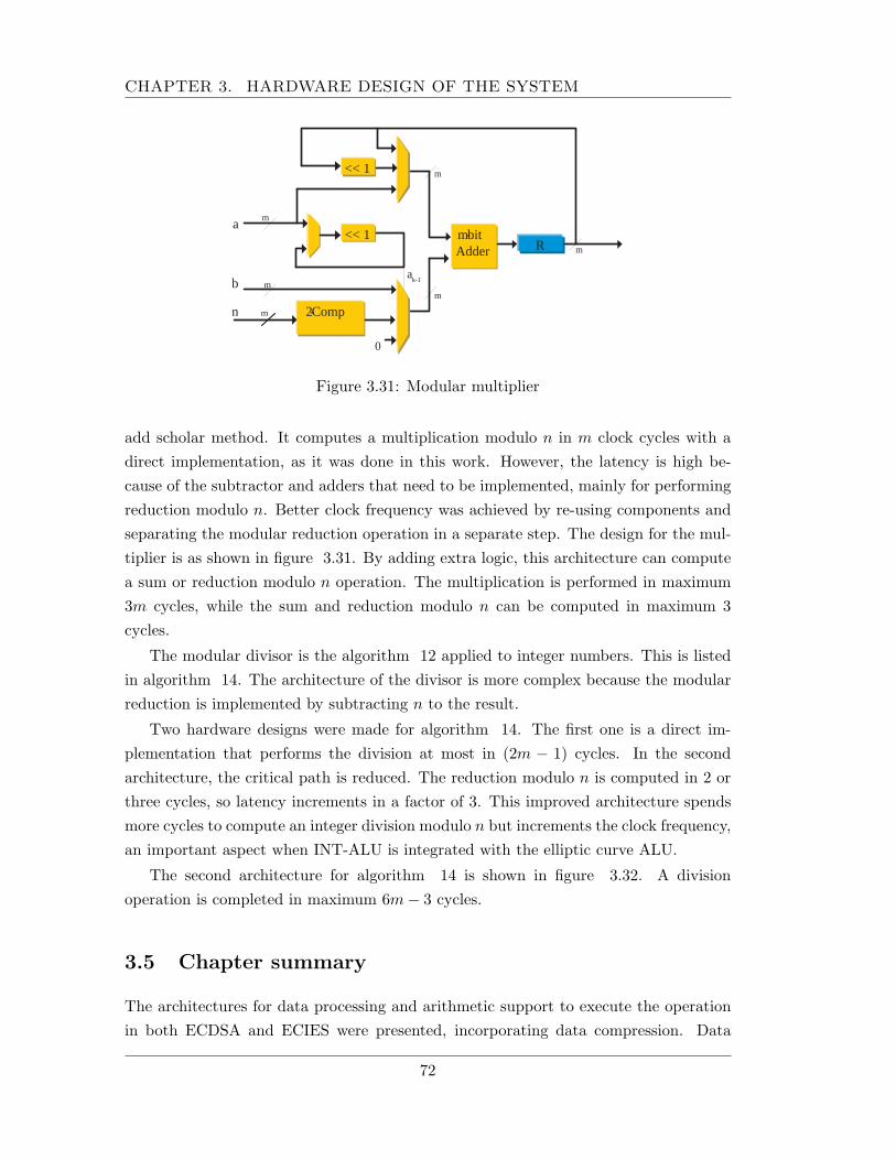
CHAPTER 3. HARDWARE DESIGN OF THE SYSTEM
a k-1
m - bit Adder
<< 1
a
b
n
R
0
2 - Comp
m
m
m
m
m
m
<< 1
Figure 3.31: Modular multiplier
add scholar method. It computes a multiplication modulo n in m clock cycles with adirect implementation, as it was done in this work. However, the latency is high be-cause of the subtractor and adders that need to be implemented, mainly for performingreduction modulo n. Better clock frequency was achieved by re-using components andseparating the modular reduction operation in a separate step. The design for the mul-tiplier is as shown in figure 3.31. By adding extra logic, this architecture can computea sum or reduction modulo n operation. The multiplication is performed in maximum3m cycles, while the sum and reduction modulo n can be computed in maximum 3cycles.
The modular divisor is the algorithm 12 applied to integer numbers. This is listedin algorithm 14. The architecture of the divisor is more complex because the modularreduction is implemented by subtracting n to the result.
Two hardware designs were made for algorithm 14. The first one is a direct im-plementation that performs the division at most in (2m − 1) cycles. In the secondarchitecture, the critical path is reduced. The reduction modulo n is computed in 2 orthree cycles, so latency increments in a factor of 3. This improved architecture spendsmore cycles to compute an integer division modulo n but increments the clock frequency,an important aspect when INT-ALU is integrated with the elliptic curve ALU.
The second architecture for algorithm 14 is shown in figure 3.32. A divisionoperation is completed in maximum 6m− 3 cycles.
3.5 Chapter summary
The architectures for data processing and arithmetic support to execute the operationin both ECDSA and ECIES were presented, incorporating data compression. Data
72
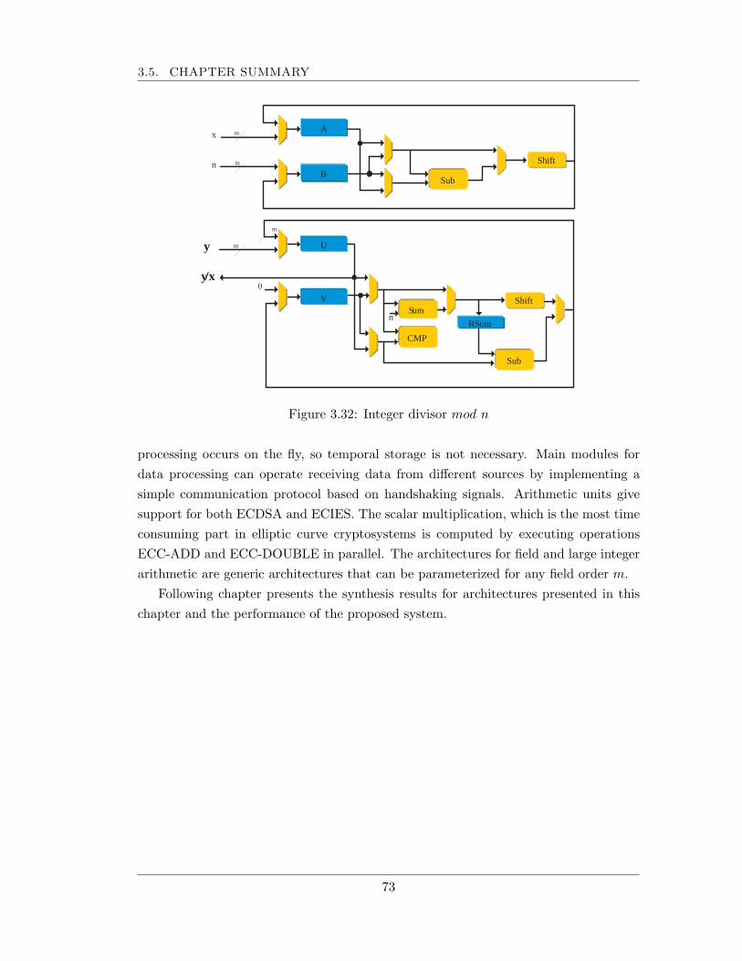
3.5. CHAPTER SUMMARY
m y
m
0 y /x
U
Shift V
n
CMP
S um
Sub
RSum
x
n
A m
m
B
Shift
Sub
Figure 3.32: Integer divisor mod n
processing occurs on the fly, so temporal storage is not necessary. Main modules fordata processing can operate receiving data from different sources by implementing asimple communication protocol based on handshaking signals. Arithmetic units givesupport for both ECDSA and ECIES. The scalar multiplication, which is the most timeconsuming part in elliptic curve cryptosystems is computed by executing operationsECC-ADD and ECC-DOUBLE in parallel. The architectures for field and large integerarithmetic are generic architectures that can be parameterized for any field order m.
Following chapter presents the synthesis results for architectures presented in thischapter and the performance of the proposed system.
73
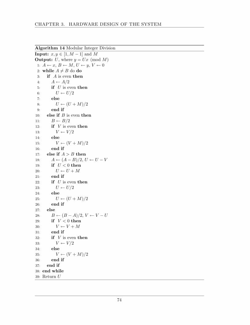
CHAPTER 3. HARDWARE DESIGN OF THE SYSTEM
Algorithm 14 Modular Integer DivisionInput: x, y ∈ [1,M − 1] and MOutput: U , where y = Ux (mod M)1: A ← x, B ← M , U ← y, V ← 02: while A 6= B do do3: if A is even then4: A ← A/25: if U is even then6: U ← U/27: else8: U ← (U + M)/29: end if
10: else if B is even then11: B ← B/212: if V is even then13: V ← V/214: else15: V ← (V + M)/216: end if17: else if A > B then18: A ← (A−B)/2, U ← U − V19: if U < 0 then20: U ← U + M21: end if22: if U is even then23: U ← U/224: else25: U ← (U + M)/226: end if27: else28: B ← (B −A)/2, V ← V − U29: if V < 0 then30: V ← V + M31: end if32: if V is even then33: V ← V/234: else35: V ← (V + M)/236: end if37: end if38: end while39: Return U
74
Chapter 4
Implementation and Results
This chapter presents the synthesis results for the system implementation and showscomparison results. The architecture was synthesized for a Xilinx VirtexII XC2V6000-4ff1176 FPGA, using the Xilinx ISE 6.x synthesis tools and simulated in Active-HDL6.2 environment.
The following section shows the synthesis results for the developed system. Firstlythe results for the data processing blocks are presented, then the results for the arith-metic units. The parameters of the architectures presented in the previous chapter fordata processing were selected from software implementation results. The parametersfor the arithmetic units, like finite field, irreducible polynomial and elliptic curve weretaken from the recommendations by NIST and SEC group.
4.1 Implementation: data processing blocks
4.1.1 Compression module
The architecture described in Chapter 3 for data compression is mainly dependenton the size of the buffers. The values for the size of the coding and searching buffersdetermine the size of registers, multiplexers, comparators and counters in the processingelements, and also, the compression ratio and latency. These sizes were selected takinginto account the results of a software implementation of the compression algorithm. Inthis work, the compressor was tested using the large Calgary corpus [46]. The corpusis a data set commonly used for evaluating lossless data compression methods, it iscomposed of 18 files, which range in size from 21 KB to 768 KB, from source code,object code, among others. The size and data-type of the files are listed in table 4.1,all file sizes in bytes.
The software version of the LZ algorithm was tested using different values for thecoding and searching buffers. From this software implementation, it was measured the
75
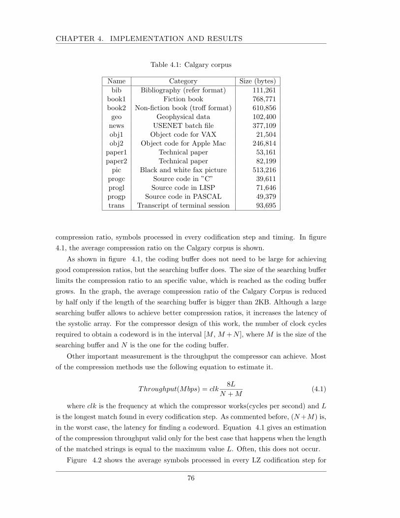
CHAPTER 4. IMPLEMENTATION AND RESULTS
Table 4.1: Calgary corpus
Name Category Size (bytes)bib Bibliography (refer format) 111,261
book1 Fiction book 768,771book2 Non-fiction book (troff format) 610,856geo Geophysical data 102,400
news USENET batch file 377,109obj1 Object code for VAX 21,504obj2 Object code for Apple Mac 246,814
paper1 Technical paper 53,161paper2 Technical paper 82,199
pic Black and white fax picture 513,216progc Source code in ”C” 39,611progl Source code in LISP 71,646progp Source code in PASCAL 49,379trans Transcript of terminal session 93,695
compression ratio, symbols processed in every codification step and timing. In figure4.1, the average compression ratio on the Calgary corpus is shown.
As shown in figure 4.1, the coding buffer does not need to be large for achievinggood compression ratios, but the searching buffer does. The size of the searching bufferlimits the compression ratio to an specific value, which is reached as the coding buffergrows. In the graph, the average compression ratio of the Calgary Corpus is reducedby half only if the length of the searching buffer is bigger than 2KB. Although a largesearching buffer allows to achieve better compression ratios, it increases the latency ofthe systolic array. For the compressor design of this work, the number of clock cyclesrequired to obtain a codeword is in the interval [M , M +N ], where M is the size of thesearching buffer and N is the one for the coding buffer.
Other important measurement is the throughput the compressor can achieve. Mostof the compression methods use the following equation to estimate it.
Throughput(Mbps) = clk8L
N + M(4.1)
where clk is the frequency at which the compressor works(cycles per second) and L
is the longest match found in every codification step. As commented before, (N +M) is,in the worst case, the latency for finding a codeword. Equation 4.1 gives an estimationof the compression throughput valid only for the best case that happens when the lengthof the matched strings is equal to the maximum value L. Often, this does not occur.
Figure 4.2 shows the average symbols processed in every LZ codification step for
76
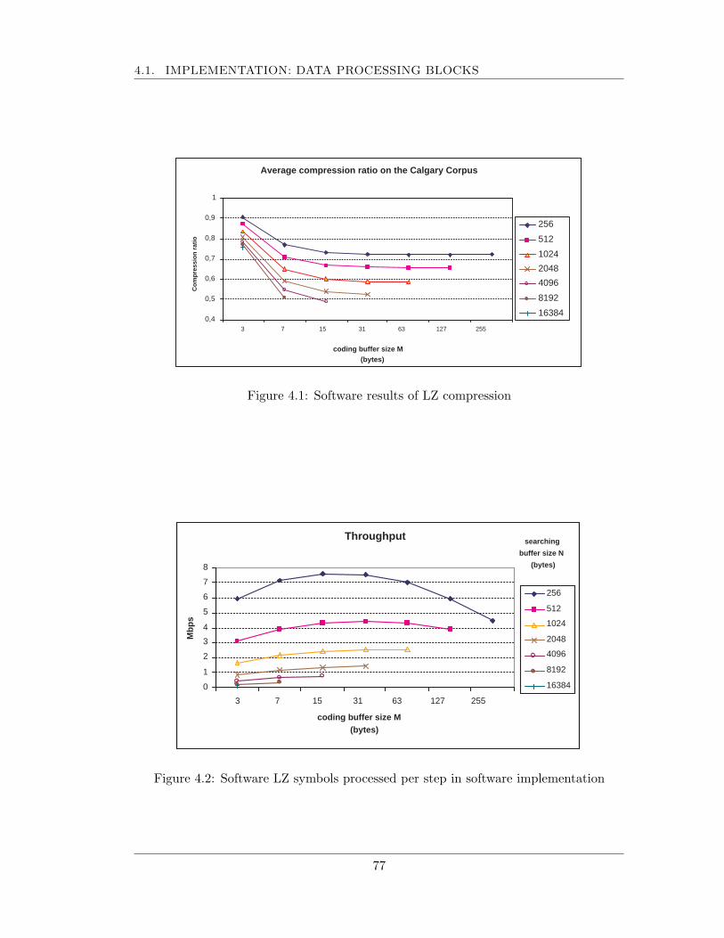
4.1. IMPLEMENTATION: DATA PROCESSING BLOCKS
Average compression ratio on the Calgary Corpus
0,4
0,5
0,6
0,7
0,8
0,9
1
3 7 15 31 63 127 255
Co
mp
ress
ion
rat
io
256
512
1024
2048
4096
8192
16384
coding buffer size M (bytes)
Figure 4.1: Software results of LZ compression
Throughput
0
1
2
3
4
5
6
7
8
3 7 15 31 63 127 255
coding buffer size M (bytes)
Mb
ps
256
512
1024
2048
4096
8192
16384
searching
buffer size N
(bytes)
Figure 4.2: Software LZ symbols processed per step in software implementation
77
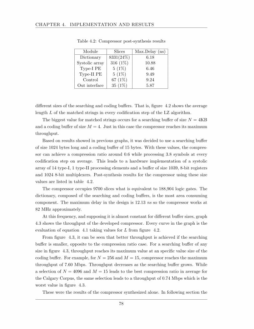
CHAPTER 4. IMPLEMENTATION AND RESULTS
Table 4.2: Compressor post-synthesis results
Module Slices Max.Delay (ns)Dictionary 8331(24%) 6.18
Systolic array 316 (1%) 10.88Type-I PE 5 (1%) 6.46Type-II PE 5 (1%) 9.49
Control 67 (1%) 9.24Out interface 35 (1%) 5.87
different sizes of the searching and coding buffers. That is, figure 4.2 shows the averagelength L of the matched strings in every codification step of the LZ algorithm.
The biggest value for matched strings occurs for a searching buffer of size N = 4KBand a coding buffer of size M = 4. Just in this case the compressor reaches its maximumthroughput.
Based on results showed in previous graphs, it was decided to use a searching bufferof size 1024 bytes long and a coding buffer of 15 bytes. With these values, the compres-sor can achieve a compression ratio around 0.6 while processing 3.8 symbols at everycodification step on average. This leads to a hardware implementation of a systolicarray of 14 type-I, 1 type-II processing elements and a buffer of size 1039, 8-bit registersand 1024 8-bit multiplexers. Post-synthesis results for the compressor using these sizevalues are listed in table 4.2.
The compressor occupies 9700 slices what is equivalent to 188,904 logic gates. Thedictionary, composed of the searching and coding buffers, is the most area consumingcomponent. The maximum delay in the design is 12.13 ns so the compressor works at82 MHz approximately.
At this frequency, and supposing it is almost constant for different buffer sizes, graph4.3 shows the throughput of the developed compressor. Every curve in the graph is theevaluation of equation 4.1 taking values for L from figure 4.2.
From figure 4.3, it can be seen that better throughput is achieved if the searchingbuffer is smaller, opposite to the compression ratio case. For a searching buffer of anysize in figure 4.3, throughput reaches its maximum value at an specific value size of thecoding buffer. For example, for N = 256 and M = 15, compressor reaches the maximumthroughput of 7.60 Mbps. Throughput decreases as the searching buffer grows. Whilea selection of N = 4096 and M = 15 leads to the best compression ratio in average forthe Calgary Corpus, the same selection leads to a throughput of 0.74 Mbps which is theworst value in figure 4.3.
These were the results of the compressor synthesized alone. In following section the
78
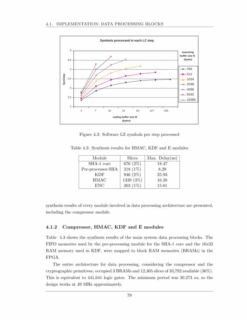
4.1. IMPLEMENTATION: DATA PROCESSING BLOCKS
Symbols processed in each LZ step
2
2,5
3
3,5
4
4,5
5
3 7 15 31 63 127 255
coding buffer size M (bytes)
Sym
/ste
p
256
512
1024
2048
4096
8192
16384
searching buffer size N
(bytes)
Figure 4.3: Software LZ symbols per step processed
Table 4.3: Synthesis results for HMAC, KDF and E modules
Module Slices Max. Delay(ns)SHA-1 core 676 (2%) 18.47
Pre-processor-SHA 218 (1%) 8.29KDF 946 (2%) 25.93
HMAC 1339 (3%) 16.28ENC 203 (1%) 15.61
synthesis results of every module involved in data processing architecture are presented,including the compressor module.
4.1.2 Compressor, HMAC, KDF and E modules
Table 4.3 shows the synthesis results of the main system data processing blocks. TheFIFO memories used by the pre-processing module for the SHA-1 core and the 16x32RAM memory used in KDF, were mapped to block RAM memories (BRAMs) in theFPGA.
The entire architecture for data processing, considering the compressor and thecryptographic primitives, occupied 3 BRAMs and 12,305 slices of 33,792 available (36%).This is equivalent to 441,641 logic gates. The minimum period was 20.273 ns, so thedesign works at 49 MHz approximately.
79
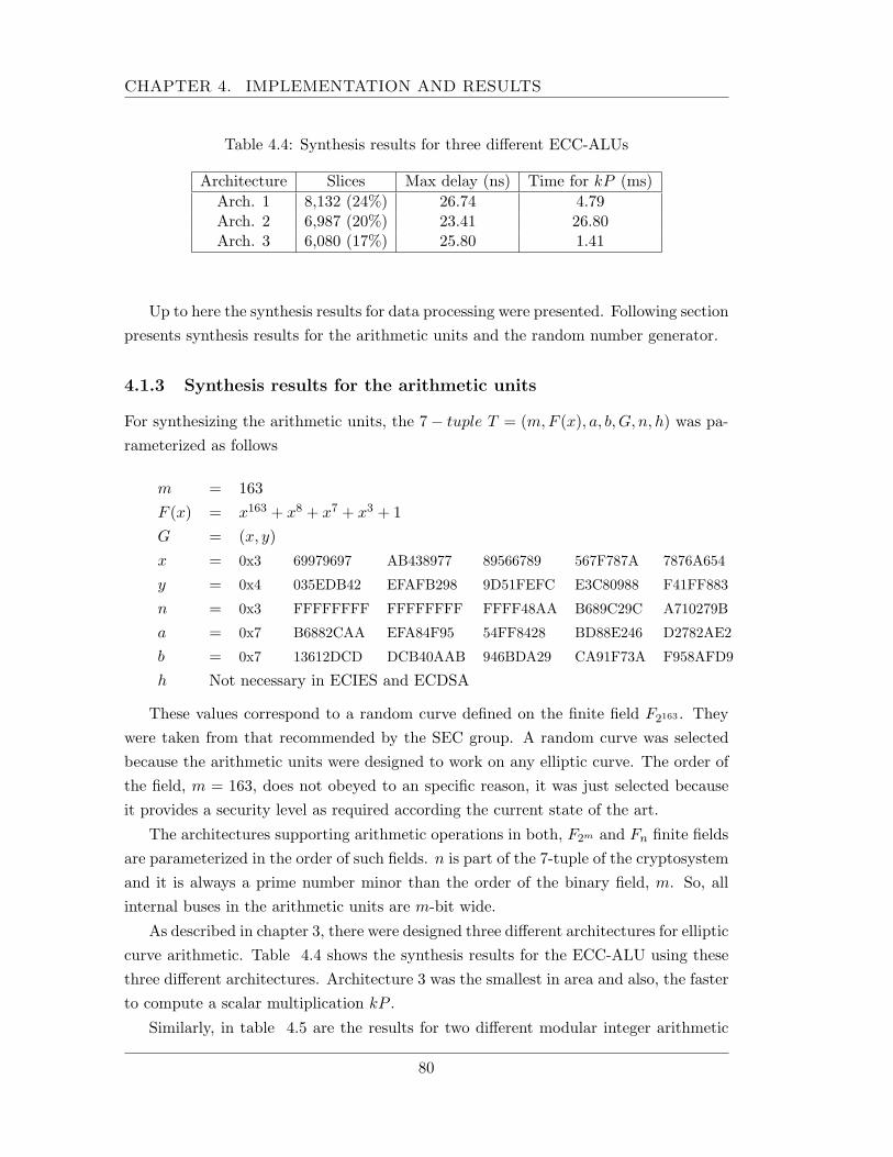
CHAPTER 4. IMPLEMENTATION AND RESULTS
Table 4.4: Synthesis results for three different ECC-ALUs
Architecture Slices Max delay (ns) Time for kP (ms)Arch. 1 8,132 (24%) 26.74 4.79Arch. 2 6,987 (20%) 23.41 26.80Arch. 3 6,080 (17%) 25.80 1.41
Up to here the synthesis results for data processing were presented. Following sectionpresents synthesis results for the arithmetic units and the random number generator.
4.1.3 Synthesis results for the arithmetic units
For synthesizing the arithmetic units, the 7− tuple T = (m,F (x), a, b,G, n, h) was pa-rameterized as follows
m = 163F (x) = x163 + x8 + x7 + x3 + 1G = (x, y)x = 0x3 69979697 AB438977 89566789 567F787A 7876A654
y = 0x4 035EDB42 EFAFB298 9D51FEFC E3C80988 F41FF883
n = 0x3 FFFFFFFF FFFFFFFF FFFF48AA B689C29C A710279B
a = 0x7 B6882CAA EFA84F95 54FF8428 BD88E246 D2782AE2
b = 0x7 13612DCD DCB40AAB 946BDA29 CA91F73A F958AFD9
h Not necessary in ECIES and ECDSA
These values correspond to a random curve defined on the finite field F2163 . Theywere taken from that recommended by the SEC group. A random curve was selectedbecause the arithmetic units were designed to work on any elliptic curve. The order ofthe field, m = 163, does not obeyed to an specific reason, it was just selected becauseit provides a security level as required according the current state of the art.
The architectures supporting arithmetic operations in both, F2m and Fn finite fieldsare parameterized in the order of such fields. n is part of the 7-tuple of the cryptosystemand it is always a prime number minor than the order of the binary field, m. So, allinternal buses in the arithmetic units are m-bit wide.
As described in chapter 3, there were designed three different architectures for ellipticcurve arithmetic. Table 4.4 shows the synthesis results for the ECC-ALU using thesethree different architectures. Architecture 3 was the smallest in area and also, the fasterto compute a scalar multiplication kP .
Similarly, in table 4.5 are the results for two different modular integer arithmetic
80
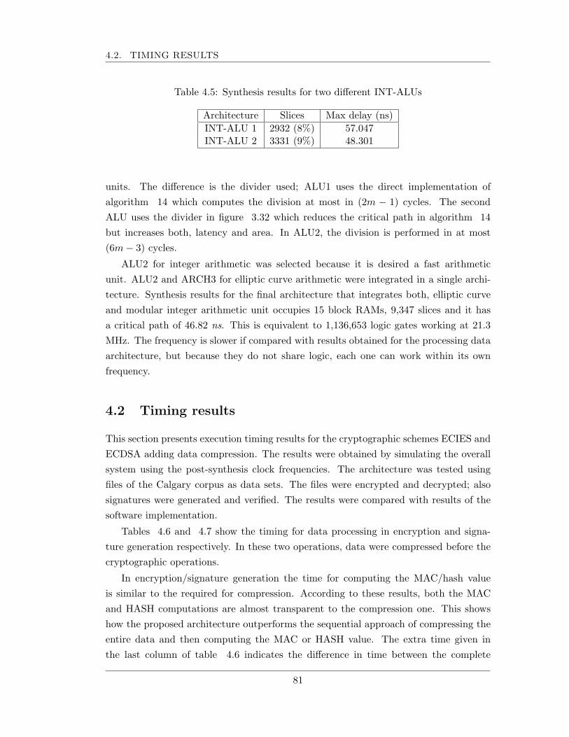
4.2. TIMING RESULTS
Table 4.5: Synthesis results for two different INT-ALUs
Architecture Slices Max delay (ns)INT-ALU 1 2932 (8%) 57.047INT-ALU 2 3331 (9%) 48.301
units. The difference is the divider used; ALU1 uses the direct implementation ofalgorithm 14 which computes the division at most in (2m − 1) cycles. The secondALU uses the divider in figure 3.32 which reduces the critical path in algorithm 14but increases both, latency and area. In ALU2, the division is performed in at most(6m− 3) cycles.
ALU2 for integer arithmetic was selected because it is desired a fast arithmeticunit. ALU2 and ARCH3 for elliptic curve arithmetic were integrated in a single archi-tecture. Synthesis results for the final architecture that integrates both, elliptic curveand modular integer arithmetic unit occupies 15 block RAMs, 9,347 slices and it hasa critical path of 46.82 ns. This is equivalent to 1,136,653 logic gates working at 21.3MHz. The frequency is slower if compared with results obtained for the processing dataarchitecture, but because they do not share logic, each one can work within its ownfrequency.
4.2 Timing results
This section presents execution timing results for the cryptographic schemes ECIES andECDSA adding data compression. The results were obtained by simulating the overallsystem using the post-synthesis clock frequencies. The architecture was tested usingfiles of the Calgary corpus as data sets. The files were encrypted and decrypted; alsosignatures were generated and verified. The results were compared with results of thesoftware implementation.
Tables 4.6 and 4.7 show the timing for data processing in encryption and signa-ture generation respectively. In these two operations, data were compressed before thecryptographic operations.
In encryption/signature generation the time for computing the MAC/hash valueis similar to the required for compression. According to these results, both the MACand HASH computations are almost transparent to the compression one. This showshow the proposed architecture outperforms the sequential approach of compressing theentire data and then computing the MAC or HASH value. The extra time given inthe last column of table 4.6 indicates the difference in time between the complete
81
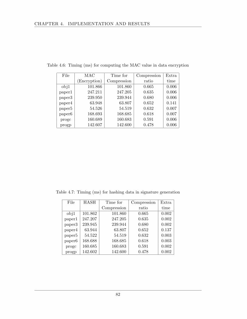
CHAPTER 4. IMPLEMENTATION AND RESULTS
Table 4.6: Timing (ms) for computing the MAC value in data encryption
File MAC Time for Compression Extra(Encryption) Compression ratio time
obj1 101.866 101.860 0.665 0.006paper1 247.211 247.205 0.635 0.006paper3 239.950 239.944 0.680 0.006paper4 63.948 63.807 0.652 0.141paper5 54.526 54.519 0.632 0.007paper6 168.693 168.685 0.618 0.007progc 160.689 160.683 0.591 0.006progp 142.607 142.600 0.478 0.006
Table 4.7: Timing (ms) for hashing data in signature generation
File HASH Time for Compression ExtraCompression ratio time
obj1 101.862 101.860 0.665 0.002paper1 247.207 247.205 0.635 0.002paper3 239.945 239.944 0.680 0.002paper4 63.944 63.807 0.652 0.137paper5 54.522 54.519 0.632 0.003paper6 168.688 168.685 0.618 0.003progc 160.685 160.683 0.591 0.002progp 142.602 142.600 0.478 0.002
82
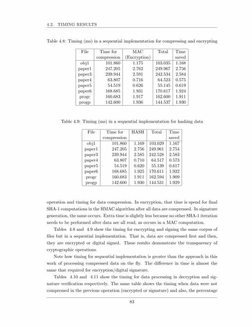
4.2. TIMING RESULTS
Table 4.8: Timing (ms) in a sequential implementation for compressing and encrypting
File Time for MAC Total Timecompression (Encryption) saved
obj1 101.860 1.175 103.035 1.168paper1 247.205 2.762 249.967 2.756paper3 239.944 2.591 242.534 2.584paper4 63.807 0.716 64.523 0.575paper5 54.519 0.626 55.145 0.619paper6 168.685 1.931 170.617 1.924progc 160.683 1.917 162.600 1.911progp 142.600 1.936 144.537 1.930
Table 4.9: Timing (ms) in a sequential implementation for hashing data
File Time for HASH Total Timecompression saved
obj1 101.860 1.169 103.029 1.167paper1 247.205 2.756 249.961 2.754paper3 239.944 2.585 242.528 2.583paper4 63.807 0.710 64.517 0.573paper5 54.519 0.620 55.139 0.617paper6 168.685 1.925 170.611 1.922progc 160.683 1.911 162.594 1.909progp 142.600 1.930 144.531 1.929
operation and timing for data compression. In encryption, that time is spend for finalSHA-1 computations in the HMAC algorithm after all data are compressed. In signaturegeneration, the same occurs. Extra time is slightly less because no other SHA-1 iterationneeds to be performed after data are all read, as occurs in a MAC computation.
Tables 4.8 and 4.9 show the timing for encrypting and signing the same corpus offiles but in a sequential implementation. That is, data are compressed first and then,they are encrypted or digital signed. These results demonstrate the transparency ofcryptographic operations.
Note how timing for sequential implementation is greater than the approach in thiswork of processing compressed data on the fly. The difference in time is almost thesame that required for encryption/digital signature.
Tables 4.10 and 4.11 show the timing for data processing in decryption and sig-nature verification respectively. The same table shows the timing when data were notcompressed in the previous operation (encrypted or signature) and also, the percentage
83
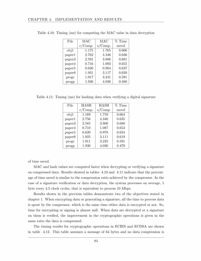
CHAPTER 4. IMPLEMENTATION AND RESULTS
Table 4.10: Timing (ms) for computing the MAC value in data decryption
File MAC MAC % Timec/Comp. s/Comp. saved
obj1 1.175 1.765 0.666paper1 2.762 4.346 0.636paper3 2.591 3.806 0.681paper4 0.716 1.093 0.655paper5 0.626 0.984 0.637paper6 1.931 3.117 0.620progc 1.917 3.241 0.591progp 1.936 4.036 0.480
Table 4.11: Timing (ms) for hashing data when verifying a digital signature
File HASH HASH % Timec/Comp. s/Comp. saved
obj1 1.169 1.759 0.664paper1 2.756 4.340 0.635paper3 2.585 3.800 0.680paper4 0.710 1.087 0.653paper5 0.620 0.978 0.634paper6 1.925 3.111 0.619progc 1.911 3.235 0.591progp 1.930 4.030 0.479
of time saved.MAC and hash values are computed faster when decrypting or verifying a signature
on compressed data. Results showed in tables 4.10 and 4.11 indicate that the percent-age of time saved is similar to the compression ratio achieved by the compressor. In thecase of a signature verification or data decryption, the system processes on average, 1byte every 4.5 clock cycles, that is equivalent to process 10 Mbps.
Results shown in the previous tables demonstrate two of the objectives stated inchapter 1. When encrypting data or generating a signature, all the time to process datais spent by the compressor, which is the same time either data is encrypted or not. So,time for encrypting or signing is almost null. When data are decrypted or a signatureon them is verified, the improvement in the cryptographic operations is given in thesame ratio the data is compressed.
The timing results for cryptographic operations in ECIES and ECDSA are shownin table 4.12. This table assumes a message of 64 bytes and no data compression is
84
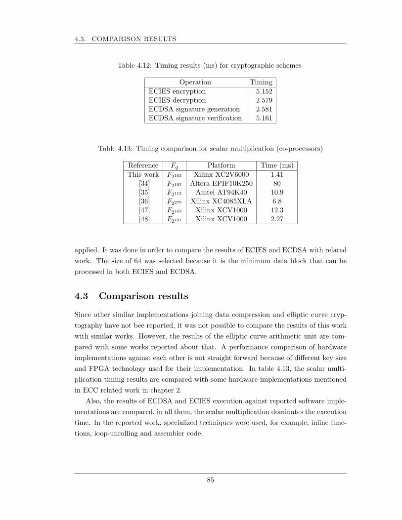
4.3. COMPARISON RESULTS
Table 4.12: Timing results (ms) for cryptographic schemes
Operation TimingECIES encryption 5.152ECIES decryption 2.579ECDSA signature generation 2.581ECDSA signature verification 5.161
Table 4.13: Timing comparison for scalar multiplication (co-processors)
Reference Fq Platform Time (ms)This work F2163 Xilinx XC2V6000 1.41
[34] F2163 Altera EPIF10K250 80[35] F2113 Amtel AT94K40 10.9[36] F2270 Xilinx XC4085XLA 6.8[47] F2163 Xilinx XCV1000 12.3[48] F2191 Xilinx XCV1000 2.27
applied. It was done in order to compare the results of ECIES and ECDSA with relatedwork. The size of 64 was selected because it is the minimum data block that can beprocessed in both ECIES and ECDSA.
4.3 Comparison results
Since other similar implementations joining data compression and elliptic curve cryp-tography have not bee reported, it was not possible to compare the results of this workwith similar works. However, the results of the elliptic curve arithmetic unit are com-pared with some works reported about that. A performance comparison of hardwareimplementations against each other is not straight forward because of different key sizeand FPGA technology used for their implementation. In table 4.13, the scalar multi-plication timing results are compared with some hardware implementations mentionedin ECC related work in chapter 2.
Also, the results of ECDSA and ECIES execution against reported software imple-mentations are compared, in all them, the scalar multiplication dominates the executiontime. In the reported work, specialized techniques were used, for example, inline func-tions, loop-unrolling and assembler code.
85
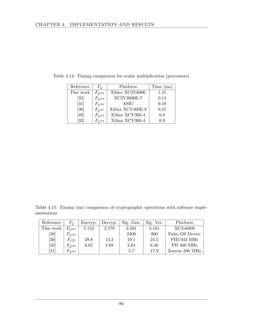
CHAPTER 4. IMPLEMENTATION AND RESULTS
Table 4.14: Timing comparison for scalar multiplication (processors)
Reference Fq Platform Time (ms)This work F2163 Xilinx XC2V6000 1.41
[32] F2163 XC2V2000E-7 0.14[31] F2160 ASIC 0.19[30] F2167 Xilinx XCV400E-8 0.21[49] F2155 Xilinx XCV300-4 6.8[33] F2176 Xilinx XCV300-4 6.9
Table 4.15: Timing (ms) comparison of cryptographic operations with software imple-mentations
Reference Fq Encryp. Decryp. Sig. Gen. Sig. Ver. PlatformThis work F2163 5.152 2.579 2.581 5.161 XC2v6000
[38] F2163 2400 900 Palm OS Device[39] F175 28.8 13.3 19.1 24.5 PIII 933 MHz[50] F2163 6.67 4.69 2.64 6.46 PII 400 MHz[51] F2163 5.7 17.9 Zaurus 206 MHz
86
Chapter 5
Concluding remarks
This chapter reviews this work including the objectives and contributions and, also thedirections of future work in order to improve the performance of the system.
5.1 Summary and contributions
This work discussed the development of a system combining lossless data compressionand public key cryptography. For data compression, a dictionary-based method wasselected due to the low hardware requirements for implementation and its applicationto any kind of data. Data compression was integrated to two elliptic curve algorithms:ECDSA and ECIES. The first one has been standardized by ISO, NIST, IEEE, ANSIand other international standard organizations. ECIES is one of the most promisingschemes for data encryption/decryption going to be standardized. In this work, inorder to outperform a software implementation, parallelization at algorithmic level wasapplied. Compression was implemented using a systolic array approach; the compressionratio, latency and area complexity depend strongly on the size of the buffers used. Thearchitectures for data processing in both, ECIES and ECDSA were unified in one unit,which computes on the fly the HASH/MAC value of incoming compressed data.
The complete system was described in VHDL and prototyped to a Xilinx VIRTEXII FPGA device. The design is parameterized on the size of the finite filed F2m , anddesigned in a modularized manner. This leads to easy further modification, for example,updating specific field or long-integer arithmetic units.
A unified architecture was designed to support the execution of both ECDSA andECIES algorithms. The same architecture can perform the four cryptographic oper-ations: encryption, decryption, signature generation and signature verification. Thesystem is composed of two independent modules, one for data processing and other forfield and long-integer arithmetic. These two units are related by two values; the secret
87
CHAPTER 5. CONCLUDING REMARKS
value, given by the arithmetic module to the data processing one for ECIES execution,and the HASH/MAC value, given by the data processing module to the arithmeticmodule for ECDSA execution. Data processing and arithmetic modules communicatethrougt a handshaking protocol, so they can work independently using each one a dif-ferent clock frequency.
Latency and area complexity in the data processing module are dominated by thesearching and coding buffers, that currently are implemented using flip-flops of theFPGA device. The maximum delay in this module is given by the SHA-1 core module,which internally performs a sum operation with five 32-bit operands.
The arithmetic units can support any elliptic curve defined on any binary finite field.Most of the area consumed is for supporting the elliptic curve arithmetic. However, thefrequency for the overall system is given by the modular integer ALU, which is theslower module of the system running at 34.39 MHz.
The throughput of the entire system is widely dominated by the throughput of thecompressor. Although a systolic array approach allows to implement the compressorwith low hardware requirements, the latency was high. For this implementation, themaximum delay for finding a 2-byte codeword was 1039 clock cycles, which leads toachieve only a throughput of 2.4 Mbps for bulk data encryption and signature gen-eration. By compressing data, almost 100% of time in cipher module is saved. Fordecryption and signature verification, throughput improves to 10 Mbps because datacompression is not required, saving the 40% of time in the cipher module.
Because no other similar implementations have been reported joining lossless com-pression and public key cryptography, performance results are not compared.
The timing results to perform arithmetic operation were acceptable compared withother reported implementation, were sophisticated techniques are implemented (ad-vanced multipliers, code optimization, better but complex algorithms, etc). In thiswork, the scalar multiplication can be performed in 1.4 ms, for small data sets, scalarmultiplication dominates the execution time of the cryptographic operations, so it isimportant to perform this operation in the least possible time.
5.1.1 Contributions summary
The first contribution of this work was the development of a hardware architecturethat combines two of the most important techniques in computer network applications:lossless data compression and public key cryptography. Such combination, and itshardware implementation had not been explored before. The results achieved showthat it is possible to consider such combination and propose better implementation inorder to improve the throughput of the complete system. The second contribution was
88
5.2. OBJECTIVES REVIEW
to propose a hardware architecture for executing elliptic curve cryptographic schemes.No such architecture has been reported in the literature.
5.2 Objectives review
The thesis objectives stated in chapter one were achieved satisfactory. The generalobjective of designing and implementing a system joining public key cryptography andlossless data compression in a single chip was successfully reached. It was possibleto combine two different algorithms, applying the operation in the correct order togather the advantages of transmitting more data, in a secure form using public keycryptography instead of traditionally symmetrical encryption and further more, usinga public key cryptosystem considered more secure than commonly used.
Specific objectives were reached, according to the results presented in previous chap-ter,
• The first objective of improving the performance of the cipher module by com-pressing data was reached, the time saving for encryption or signature generationswas almost of the 100%, all time required is only to perform compression, whatis the same either data is encrypted or not. When decrypting data or verifyinga digital signature, time to perform these operation reduces in the same ratio asthe compression ratio achieved.
• The second objective was to better utilize the available bandwidth by compressingdata before encryption. This objective was reached; the percentage of time savedis similar to the compression ratio achieved by the compressor.
5.3 Directions
Directions on this work are for timing improvement in critical modules and hence, im-proving the throughput of the overall system. First, throughput for encryption/signaturegeneration can be improved by improving the compressor’s throughput. The compres-sor can be implemented by using the CAM approach instead of using the systolic one.Although area resources will increase considerably, up to one symbol per clock cyclewill be processed, improving of this manner the throughput for data encryption andsignature generation.
For decryption and signature verification, timing will improve by optimum imple-mentation of adders in the SHA-1 core module. A 5 32-bit operand adder determinesthe critical path in this module that can be implemented by using different adders (i.e.carry save adder).
89
CHAPTER 5. CONCLUDING REMARKS
Timing for elliptic curve arithmetic can be improved following several ways: Oneoption is to implement the Itoh-Tsujii inversion algorithm, which is computed in 8 clockcycles at the cost of complex control. The second is to use projective coordinates andkeep the binary method. This eliminates the inversion operation that is the most timeconsuming in both ECC-DOUBLE and ECC-ADD operations. Field multiplication canbe improved if the digit in the multiplier is incremented at the cost of more area. Thethird option is to implement the Montgomery method [42] and also, use projectivecoordinates.
Timing for modular integer arithmetic can be improved by better implementationof adders and substractors required in the architectures, using techniques reported in[52] in order to reduce the critical path.
The system can support a protocol to establish the 7-tuple necessary to define theelliptic curve cryptosystem.
90
List of Figures
1.1 Symmetrical cryptography . . . . . . . . . . . . . . . . . . . . . . . . . . 61.2 Asymmetrical cryptography . . . . . . . . . . . . . . . . . . . . . . . . . 61.3 Digital signature . . . . . . . . . . . . . . . . . . . . . . . . . . . . . . . 71.4 Internal structure of an FPGA . . . . . . . . . . . . . . . . . . . . . . . 121.5 Internal structure of a typical configurable logic block of the Virtex II
family . . . . . . . . . . . . . . . . . . . . . . . . . . . . . . . . . . . . . 131.6 Flow design of the system . . . . . . . . . . . . . . . . . . . . . . . . . . 17
2.1 Average compression ratio for some lossless data compressors . . . . . . 202.2 Some lossless hardware implementations . . . . . . . . . . . . . . . . . . 212.3 Buffers for LZ data compression . . . . . . . . . . . . . . . . . . . . . . . 222.4 Step 1 a) and 2 b) in the LZ77 algorithm . . . . . . . . . . . . . . . . . 23
3.1 Block diagram of the system . . . . . . . . . . . . . . . . . . . . . . . . . 393.2 ECIES scheme data flow. a) encryption, b) decryption . . . . . . . . . . 403.3 Processing data for ECIES: addition of a data compression module . . . 413.4 Data flow for signature generation/verification in the ECDSA scheme . 423.5 Data compression added to ECDSA . . . . . . . . . . . . . . . . . . . . 433.6 Data processing for ECDSA and ECIES . . . . . . . . . . . . . . . . . . 473.7 SHA-1 core . . . . . . . . . . . . . . . . . . . . . . . . . . . . . . . . . . 483.8 Message Scheduler for SHA-1 core . . . . . . . . . . . . . . . . . . . . . 493.9 HMAC algorithm . . . . . . . . . . . . . . . . . . . . . . . . . . . . . . . 503.10 Prepocessing module for SHA-1 . . . . . . . . . . . . . . . . . . . . . . . 503.11 Key derivation function KDF . . . . . . . . . . . . . . . . . . . . . . . . 513.12 Basic cells . . . . . . . . . . . . . . . . . . . . . . . . . . . . . . . . . . . 533.13 Unrolling the LZ algorithm . . . . . . . . . . . . . . . . . . . . . . . . . 543.14 Processing elements . . . . . . . . . . . . . . . . . . . . . . . . . . . . . 553.15 The systolic array . . . . . . . . . . . . . . . . . . . . . . . . . . . . . . 563.16 Buffers for LZ compression . . . . . . . . . . . . . . . . . . . . . . . . . 573.17 Architecture for arithmetic support . . . . . . . . . . . . . . . . . . . . . 58
91
LIST OF FIGURES
3.18 Scalar multiplication levels . . . . . . . . . . . . . . . . . . . . . . . . . 593.19 Sum of different points, ECC-ADD . . . . . . . . . . . . . . . . . . . . . 613.20 Sum of equal points, ECC-DOUBLE . . . . . . . . . . . . . . . . . . . . 623.21 Serial multiplier . . . . . . . . . . . . . . . . . . . . . . . . . . . . . . . . 633.22 Interter for F2m . . . . . . . . . . . . . . . . . . . . . . . . . . . . . . . . 643.23 Digit serial multiplier for F2m . . . . . . . . . . . . . . . . . . . . . . . . 663.24 Main reduction module for the digit-serial multiplier . . . . . . . . . . . 663.25 Squarer for F2m . . . . . . . . . . . . . . . . . . . . . . . . . . . . . . . . 673.26 Architecture for add operation, ECC-ADD . . . . . . . . . . . . . . . . . 683.27 Architecture for double operation, ECC-DOUBLE . . . . . . . . . . . . 703.28 Architecture for division in F2m . . . . . . . . . . . . . . . . . . . . . . . 703.29 Architecture for add operation, ECC-ADD . . . . . . . . . . . . . . . . . 713.30 Architecture for double operation, ECC-DOUBLE . . . . . . . . . . . . 713.31 Modular multiplier . . . . . . . . . . . . . . . . . . . . . . . . . . . . . . 723.32 Integer divisor mod n . . . . . . . . . . . . . . . . . . . . . . . . . . . . 73
4.1 Software results of LZ compression . . . . . . . . . . . . . . . . . . . . . 774.2 Software LZ symbols processed per step in software implementation . . 774.3 Software LZ symbols per step processed . . . . . . . . . . . . . . . . . . 79
92
Bibliography
[1] D. Salomon, A Guide to Data Compresion Methods. NY: Springer-Verlag, 2002.
[2] I. Witten, A. Moffat, and T. Bell, Managing Gigabytes: Compressing and IndexingDocuments and Images. CA: Academic Press, 1999.
[3] W. Stallings, Cryptography and Network Security. NJ: Prentice Hall, 2003.
[4] B. Schneier, Applied Cryptography. NY: John Wiley & Sons, 1996.
[5] J. Ziv and A. Lempel, “A Universal Algorithm for Sequential Data Compression,”IEEE Transactions on Information Theory, vol. 23, pp. 337–343, May 1977.
[6] J. Ziv and A. Lempel, “Compression of Individual Sequences via Variable-RateCoding,” IEEE Transactions on Information Theory, vol. 24, pp. 530–536, 1978.
[7] W. Diffie and M. Hellman, “New Directions in Cryptography,” IEEE Transactionson Information Theory, vol. IT-22, pp. 644–654, November 1976.
[8] R. Dahab and J. Lopez, “An Overview of Elliptic Curve Cryptography,” Tech. Rep.IC-00-10, State University of Campinas, Brazil, May 2000.
[9] K. Compton, “Reconfigurable Computing: A Survey of Systems and Software,”ACM Computing Surveys, vol. 34, pp. 171–210, June 2002.
[10] T. Wollinger and C. Paar, “How Secure are FPGAs in Cryptographic Applica-tions?.” Cryptology ePrint Archive, Report 2003/119, 2003. http://eprint.iacr.org/.
[11] HiFn, Inc, “The first book of compression and encryption.”Hifn Whitepaper, available at http://www.hifn.com/docs/a/
The-First-Book-of-Compression-and-Encryption.pdf.
[12] PKWare, Inc, “Pkware Extends ZIP Standard to Support Strong Encryp-tion.” Available at http://www.pkware.com/news events/press releases/
2003/060203-appnote.html.
93
BIBLIOGRAPHY
[13] Proginet, Co, “Product Information Guide.” Available at http://www.
proginetuk.co.uk.
[14] R. Friend and R. Monsour, “RFC 2395-IP Payload Compression Using LZS.” Avail-able at http://rfc.sunsite.dk/rfc/rfc2395.html.
[15] D. Huffman, “A Method for the Construction of Minimum Redundancy Codes,”in Proceedings of de IRE, 40(9), pp. 1098–1101, 1952.
[16] H. Park and V. Prasanna, “Area Efficient VLSI Architecture for Huffman Cod-ing,” IEEE Transactions on Circuits and Systems II: Analog and Digital SignalProcessing, vol. 40, pp. 568–575, September 1993.
[17] L. Liu et al, “CAM-Based VLSI Architectures for Dynamic Huffman Coding,”IEEE Transactions on Consumer Electronics, pp. 282–288, August 1994.
[18] N. Ranganathan and S. Henriques, “High-Speed VLSI Designs for Lempel-Ziv-based Data Compression,” IEEE Transactions on Circuits and Systems II, pp. 96–106, February 1993.
[19] B. Jung and W. Burleson, “Efficient VLSI for Lempel-Ziv Compression in WirelessData Communication Networks,” IEEE Transactions on Very Large Scale Integra-tion Systems, vol. 6, pp. 475–483, September 1998.
[20] T. Welch, “A Technique for High-Performance Data Compression,” IEEE Com-puter, vol. 17, pp. 8–19, June 1984.
[21] J. Storer and T. Syzmanski, “Data Compression via Textual Substitution,” Journalof the ACM, pp. 928–951, June 1982.
[22] S. Hwang and C. Wu, “Unified VLSI Systolic Array Design for LZ Data Com-pression,” IEEE Transactions on Very Large Scale Integration Systems, vol. 9,pp. 489–499, August 2001.
[23] W. Huang, N. Saxena, and J. McCluskey, “A Reliable LZ Data Compressor on Re-configurable Coprocessors, IEEE Sym. on Field Programmable Custom ComputingMachines, 2000.”
[24] N. Koblitz, “Elliptic Curve Cryptosystems,” Mathematics of Computation, vol. 48,pp. 203–209, November 1987.
[25] V. Miller, “Use of Elliptic Curves in Cryptography,” in Proc. of Advances in Cryp-tology, CRYPTO’85, (Santa Barbara, CA), pp. 417–426, August 1985.
94
BIBLIOGRAPHY
[26] J. Pollar, “Monte Carlo Methods for Index Computation mod p,” Mathematics ofComputation, vol. 32, pp. 918–924, 1978.
[27] SEC1, “Elliptic Curve Cryptography: Standards for Efficient CryptographyGroup.” http://www.secg.org.
[28] American Bankers Association, “ANSI X9.62-1998: Public Key Cryptography forthe Financial Services Industry: The Elliptic Curve Digital Signature Algorithm(ECDSA).”
[29] NIST, “FIPS 180-2: Secure Hash Standard (SHS).” http://csrc.nist.gov/
publications/fips/.
[30] G. Orlando and C. Paar, “A High-Performance Reconfigurable Elliptic Curve Pro-cessor for GF(2m),” in Proc. of the Second International Workshop on Crypto-graphic Hardware and Embedded Systems, CHES’2000, vol. 1965 of Lecture Notesin Computer Science, (Worcester, MA), pp. 41–56, Springer, August 2000.
[31] A. Satoh and K. Takano, “A Scalable Dual-Field Elliptic Curve CryptographicProcessor,” Transactions on Computers, vol. 52, pp. 449–460, April 2003.
[32] H. Eberle, N. Gura, and S. Chang, “A Cryptographic Processor for ArbitraryElliptic Curves over GF(2m),” in Proc. of IEEE 14th International Conferenceon Application-specific Systems, Architectures and Processors,ASAP’2003, TheHague, The Netherlands, pp. 444–454, June 2003.
[33] T. Kerins et al., “Fully Parameterizable Elliptic Curve Cryptography Processorover GF(2m),” in Proc. of 12th International Conference on Field ProgrammableLogic and Application, FPL’2002, vol. 2438 of Lecture Notes in Computer Science,(Montpellier, France), pp. 750–759, Springer, September 2002.
[34] S. Okada et al., “Implementation of Elliptic Curve Cryptographic Coprocessor overGF(2m) on a FPGA,” in Proc. of the Second International Workshop on Crypto-graphic Hardware and Embedded Systems, CHES’2000, vol. 1965 of Lecture Notesin Computer Science, (Worcester, MA), pp. 25–40, Springer, August 2000.
[35] M. Ernest et al., “A Reconfigurable System on Chip Implementation for EllipticCurve Cryptography over GF(2n),” in Proc. of the 4th International Workshop onCryptographic Hardware and Embedded Systems - CHES’2002, vol. 2523 of LectureNotes in Computer Science, (Redwood Shores, CA), pp. 381–399, Springer, August2002.
95
BIBLIOGRAPHY
[36] M. Ernest et al., “Rapid Prototyping for Hardware Accelerated Elliptic CurvePublic Key Cryptosystems,” in Proc. of 12th IEEE Workshop on Rapid SystemPrototyping, RSP’2001, (Monterey, CA), pp. 24–31, June 2001.
[37] D. Hankerson, L. Lopez, and A. Menezes, “Software Implementation of Ellip-tic Curve Cryptography over Binary Fields,” in Proc. of the Second Interna-tional Workshop on Cryptographic Hardware and Embedded Systems, CHES’2000,vol. 1965 of Lecture Notes in Computer Science, (Worcester, MA), pp. 1–24,Springer, August 2000.
[38] A. Weimerskirch, C. Paar, and S. Chang, “Elliptic Curve Cryptography on a PalmOS Device,” in Proc. of the 6th Australasian Conference, ACISP’2001, vol. 2119of Lecture Notes in Computer Science, (Sydney, Australia), pp. 502–513, Springer,July 2001.
[39] E. Konstantinou, Y. Stamatiou, and C. Zaroliagis, “Software Library for Ellip-tic Curve Cryptography,” in Proc. of 10th Annual European Symposium on Algo-rithms, ESA’2002, vol. 2461 of Lecture Notes in Computer Science, (Rome, Italy),pp. 625–637, Springer, September 2002.
[40] “Lidia. A Cryptographic Library.” Technical University of Darmstadt, Germany.Available from http://www.informatik.tudarmstadt.de/TI/LiDIA/Welcome.
html.
[41] “Miracl: Big number library.” Available at http://indigo.ie/∼mscott/.
[42] J. Lopez and R. Dahab, “Fast Multiplication on Elliptic Curves over gf(2m) with-out Precomputation,” in Proc. of the First International Workshop on Crypto-graphic Hardware and Embedded Systems, Lecture Notes in Computer Science,pp. 316–327, Springer, 1999.
[43] T. Grembowski et al, “Comparative Analysis of the Hardware Implementations ofHash Functions SHA-1 and SHA-512,” in Proc. of the 5th International Conferenceon Information Security, Lecture Notes in Computer Science, pp. 75–89, Springer,2002.
[44] J. Lutz, “High Performance Elliptic Curve Cryptographic Co-processor,” Master’sthesis, University of Waterloo, 2003.
[45] Shantz, S. C., “From Euclid’s GCD to Montgomery Multiplication to the GreatDivide,” Tech. Rep. TR-2001-95, Sun Microsystems Laboratories, 2001.
96
BIBLIOGRAPHY
[46] T. Bell, I. H. Witten, and J. G. Cleary, “Modeling for Text Compression,” ACMComputing Surveys, vol. 21, pp. 557–591, December 1989.
[47] Y. Choi et al., “Implementation of Elliptic Curve Cryptographic Coprocessor overGF (2163) for ECC protocols,” in 2002 International Technical Conference on Cir-cuits/Systems Computers and Communications, (Phuket, Thailand), July 2002.
[48] M. Bednara et al., “Reconfigurable Implementation of Elliptic Curve Crypto Al-gorithms,” in Proc. of 9th Reconfigurable Architectures Workshop, RAW’02, (FortLauderdales, Florida), April 2002.
[49] K. Leung et al., “Fpga Implementation of a Microcoded Elliptic Curve Crypto-graphic Processor,” in Proc. of IEEE FCCM 2000, (Napa Valley), pp. 68–76, 2000.
[50] M. Brown et al., “PGP in Constrained Wireless Devices,” in Proc. of the 9thUSENIX Security Symposium, (Denver, Colorado), pp. 247–262, August, 2000.
[51] I. Riedel, “Security in Ad-hoc Networks: Protocols and Elliptic Curve Cryptogra-phy on an Embedded Platform,” Master’s thesis, Ruhr-Universitat Bochum, 2003.
[52] C. Koc, “RSA Hardware Implementation,” Tech. Rep. TR-801, RSA LAboratories,Redwood City, May 1996.
97