Embed Size (px)
Citation preview
GENERALO*ELEC~TRIC
SCHENECTADY, NEW YORK
HARD IMAN I ARM TEST
HARDIMAN I PROTOTYPE PROJECT
Prepared by
Specialty Materials Handling Products OperationGeneral Electric Company
Schenectady, New York 12305
December 31, 1969
Supported Jointly by
Engineering Psychology Programs OfficeOffice of Naval ResearchWashington, D.C. 240360
Naval Air Systems CommandWashington, D.C. 20360
u Army Mobility Equipment Research and Development CenterPort lBelvoir, Virginia 22060
United States Army Project No. IM62410105072
This document has been approved for publi re-~ease and sale; its distribution is unlirr.AUed.
ONR Contract Number N000 14-66 -CO051
Work Unit Number Nfl 196-049
S -70 -1019IL28
HARDIMAN i ARM TEST
HARDIMAN I PROTOTYPE PROJECT
Supported Jointly by
Engineering Psychology Programs Office
Office of Naval Research
Washington, D. C. 20360
Naval Air Systems Command
Washington, D. C. 20360
Army Mobility Equipment Research and Development Center
Fort Belvoir, Virginia 22060
United States Army Project No. 1.1b-2410/05072
Isork Unit Number NR 10 b-O49
ONR Contract Nurber N00U114-U6-CO051
December 31, 1960
Prepared by
Specialty Mlaterials Handling Products OperationGeneral Electric Company
Schenectady, New York 12305
This document has been approved for public re-
lease and gale; its distribution is unlimited.
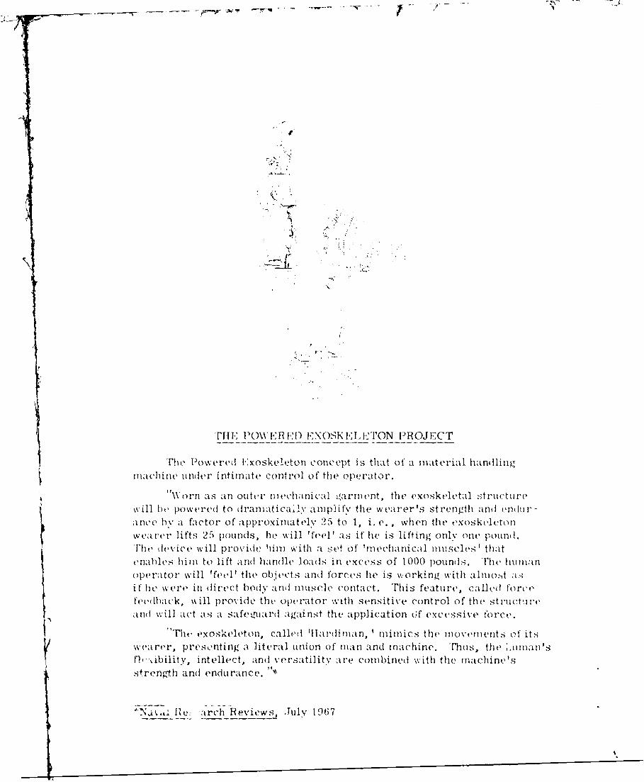
T'Fi POWERElD EXOSKELELTON PROJECT
'Fie owered I:xoskeleton concept is that of a material handlingmachine under intimate control of the operator.
Worn as an outer IIIeChIalnical rarient , the exoskeletal Structuzrewill het po~wered to dvanmatica.,ly amrplify the wearer's strength and endtir-Ince hy a factor of approximlatelY 25 to 1, i. e. , when thlt exoskeletonwearer lifts 25 pounds, he will 'fe~el ' as if hie is lifting only one pound,.
Tedevice will Prvd imwt et of' 'm~echanlical mluscles', thatt'r
feedhack, wlprvdth cao with sensitive control of the st ruct, weadv,-ill act as a saeadaantthe application (;f excessive COI~e.
''ThC e'XOSkelVetonl, called 'II ardi man, 'mimlics the movemnitts of itsw~ea rer, presonting a. literal un~ion of man and machine. Thus, thet .0 Inans
f\ribilitY, intellect, and vestlt are combined with the machine'sstrength and endurance. 97
FOREWORD
A prototype having the capability to implement the powered exoskeleton con-cept has been defined and reduced to engineering drawings suitable for part fab-
rication and assembly.
Fabrication and assembly of the complete leg ani girdle system to demon-
strate the walking capability is underway.
This report is a description of the test and evaluation of the left armassembly.
The Appendices of this report contain performance and design data on theelectronic circuits and servo system.
ACKNOWLEDGEMENTS
The Government scientific officers and projecL monitors who have directed
this program and provided constructive guidance during the period covered by
this report are:
Mr. G. S. MaleckiOffice of Naval Research
Engineering Psychology Programs
Washington, D. C. 20360
Dr. M. J. FarrOffice of Naval Research
Engineering Psychology Programs
Washington, D. C. 2030o
Dr. J. b. Millerf fice of Naval .Research
Engineering Psycho lov Program'sWashington, D. C. 20 ;t0
Mr.1 P. P. Kane
Lnited States Armv Mob ilitv Equipment
Reseatrch and Pevelopment Center
Fort Be lvoir, irginia 22 ;o
We would like to thank those mentioned below tor their interest and encour-aernent co ,his program.
'-'r. G, . . everNaval Air Svs~e,7s I o=anlikode Air-• ,'sh ington, P. ,. CJ,
Nava I "upp y "' .s ',o.man:Code , I;vasifigt,,n,.. ,: '
Xr. Sal vatore 'San ,1ippoN aval A r ~vs t,.m ,,':man.! K .,q :' -" rs/i, Mo Im :ions ' I!i i':,<
O0t i ond (io:'._t itut ion Av t'.ue
ashingt.on, . . . 2, 00
i 'i
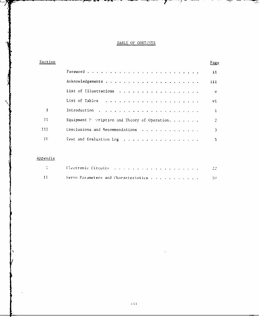
TABLE OF CONTE~NTS
Section Page
Foreword. ............................ ii
Acknowledgements ......................... iii
List of Illustrations.......................v
List of Tables.........................vi
I Introduction.................... . . ... . .. .. .. .......
TI Equipment P1 cription and Theory of Operation... .. .. ......
III Conclusions and Recommendations..................3
IV Test and Evaluation Log......................5
Append ix
I Electronic Circuits ....................... 2-1
I 1 Servo Parameters and Characteristics .. ............. 50
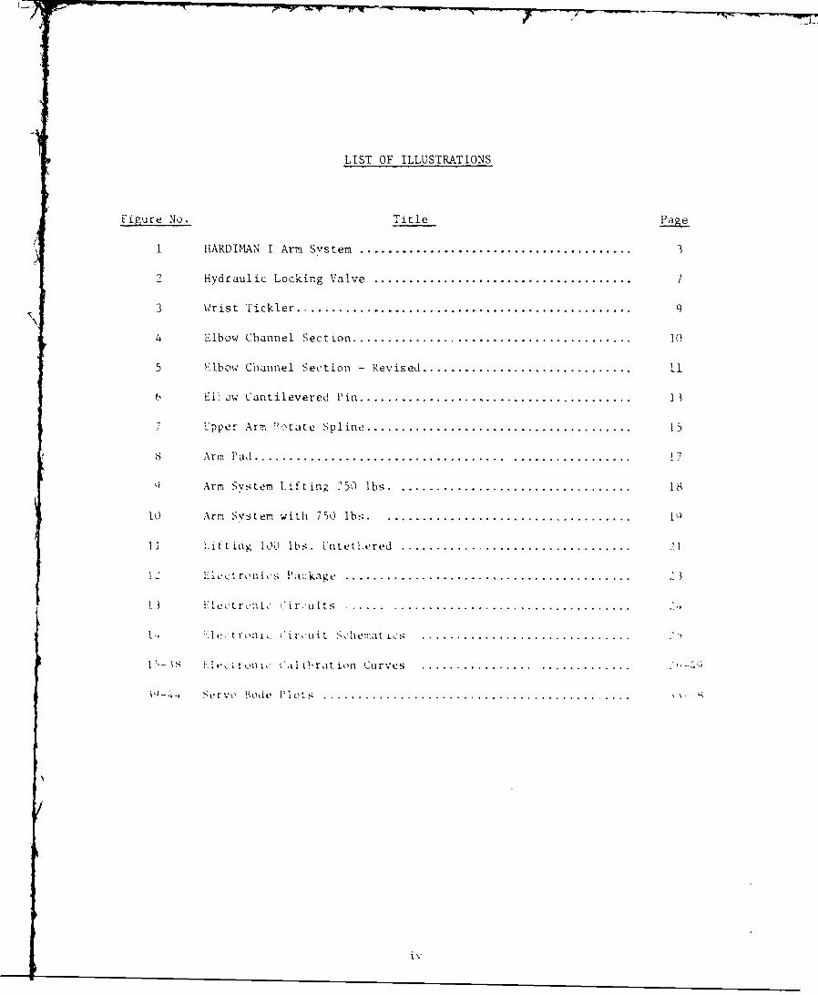
LIST OF ILLUSTRATIONS
Figure No. Title Page
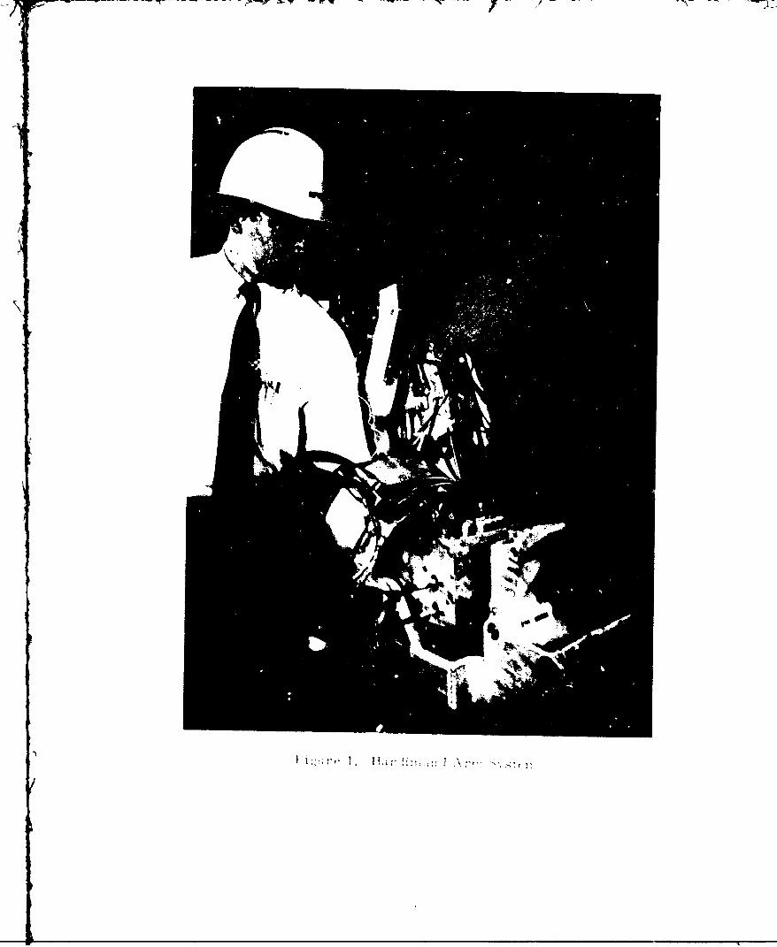
1 HARDIMHAN I Arm System............................................3
2 Hydraulic Locking Valve..........................................7
3 Wrist Tickler................................................... 9
4 Elbow Channel Section............................................. 1(
5 Elbow Channel Section - Revised ................................... 1
6 E1I'>ow Cantilevered Pin ........................................... 13
Upper Arnm'~tr Spline .......................................... 15
8 A rmi Pad........................................ ................. 1
QArm System I-ftiniz 250 lbs ...................................... 1
lo. Arm svstem with 7W0 lbs......................................Q
II ~ lt t in g 100 lbs. Untelxred.....................................]
le i ron ic s Pac kakz..............................................2
.... 'U itS..........................................
K] ~ ru Circuit Stct s.................................
iS It-,ron ic Cal i'raition Curves....................................
S Vrvo Bode P1 uts .............................................
LIST OF TABLES
Table No. Title aZ
1 Electronic Servo Parameters..................51
2 Servo Performance. ...................... 52
rV
SECTION I
INTRODUCTION
The test and evaluations of tlie Hardiman I arm system marked thle first timein the program that bilateral servo j'oints had been operated in series. Previoustests on the single joint simulator and the unilateral leg system gave promisingresults, but were not nearly as meaningful as was the successful operation of tilearm system.
With the main objective being stable operation under full load, the test andevaluation was carried out with an awareness of the follb-wing possible problemareas:
1. Individual joint instability.
2. Jc ints- in-Series instability.
3. Kinem,,atic interactions between. tickler inputs.
.4. M"echanical interferences and Ilimi tat ion,-;
~. Inabil itv oi tCie operator- t., con trc I the systemn.
tL xcess iv\e moment app~Ilied to thle ope rat or due to ljifft; enCes inllengths ,I master and slave hands
Fati ueO~.,pei ator due to lack o:mastrcutre1h n:
Al though each or Ltese protblems were observed durinsz til evjio; xon
w.ere so di i"icul t or troublesome thatt a1 solut ion consistenit wich met m~Teec I :s ould not 1,v 'p ihe wi thin the test plans. w"ith mnrec.
thlere were no hnesinl the mechanicall con I gurat ion and servo t: imeters -z-omthJose PreVsCented in H'rotS"~1 ~.dtdJuly I. I %'Q
SECTION II
EqUIPMENT DESCRIPTION AND THEORY OF OPEATI N
The Hardiman I arm system, Figure 1, is a master-slave svstem containing
eight powered joints. "x of the joints are bilateral servo controlled. These
joints are: wrist flex, forearm rotate, elbow flex, upper arm rotate, shoulder
flex, and back flex. The thumb tin and thumb flex joints are rate controlled
utilizing a velocity valve.
The o7erator makes contact with the master structure at three points -- the
hand, the wrist, and the tipper forearm. These latter two contact points are re-
quired because the six joits form an unconstrained system. Th-it is to say, the
operaror cannot define the articulation of the master Aith only one, in-ut.
hen the operator places the master in a ;articular configuration, the Al-
svncironization error between the master and slave is measured at each toint Kya tickler mechanism. These errors are converted to electrical signals by trans-
ducers and then conditioned and amplified by electron ic amplifiers These sig-
nals are then transmitte to appropriate ect rohvdrau ic servo vailves which pro-duce differential pressure proportional to the electrical si.nal. This pressure
is applied to the slaLve actuator :or the corresponding loint anj can;ses the jointto move in the same direction as the maher. The slave conti-ues to move until
the desvnchronization error is reduced to a level that wilI :maintain the svste!-in eq-i~ibrium. The ii.erenti al pressur is also aprlie, :o the "orce _eed".h..,
actutrator at each itnt. tese actuAtors ar: designred so that e operator wi !
feel a !orce, 1 ',th o: that app'ted to rac slave and in the s.-. i . :ect in.lsvnse.
hydrauli c t'e r was supp-. t v , iA 'o ' lihwr.iat rv .s,. v .. :,,' surip' v
pressire was ,W :a 04v, r, - si a .t: v K. rv. .. t ri, a to .. .. .A. Clew-
t ric sl. ,,' %% ,c ' ."'% s s , ;,'r .,t ,k 0,. ,';n W loki ng i: ,as '
/a
SECTION III
CONCLUS IONS AND IRECOMIIENDAT IONS
The successful completion of the arm test gave new confidence in the des enanid analvsis of servo joints-in-series. The model used for simulating tihe servosystem has been found to be very accurate- ifl representing thle dynamics off thesvs tom.
thie hiuman factors involved in controlling the six motions, although comol -1oxin naturte, did1 nt present any unfores-en prob lems. With spat'I c spnnc
an,: 7orce reflect ion, it was vossibl to , o-oezate the maculine sat is: a4 orli lv withJW~'.fl~riaMOunt of exp-erience?.
"he armr system test was not only valuable beccause it sub~st ant iatel tasi&: "e-s ign iecisiorns in these two tild, ut it wals also us eful IOr ivs gtnp rob Iem, areas, and' finding sotlut ions . The ;'oilowinv receinmenlatCens hv eT e
* A Minimum le0akage r-ace across the p'ilot pito hld, bes"0 ewtien nturchas inz tie p ilot oper ated !lock '.a 'Ies
* ;m-n detetrm ining maximum flow rates -oy so rvovi Ivesl ,1 areater
~ in sould e appl1 ed' to comronsate :'r uinforeseen aIctUtitr-
* Sorvov 1 es v tovery gwod 4vnarnic response shoul bdhoed evenScwornc~ tuh'\ t.IV iArger flow capacittes thtan is recqtlrvAl
.tug9 Parts su1 as''.- no!tV.t i lnsi eframAn,..tiper rm oct-t t ikesso~h u ottt rct.A
*~~~~ tu roum 'n iptt syVstem hul e-td tM ttx te pe1-
or ca otro 4 it morev east i v T h osl tv of t;s :n1o-:C':~~~ ~ ~ ~ 0! etVT" a.e i
k outjcrwe -4ght ug te mast orel,~ : .~ :rr:
anC "~:oAl. !,uAto is '" o be AccnPihd
* lft ugo ':oun s Is to v 1e onever o , .cn :h- ~ ~ ~ c I I *"'o31 ' ' tC iL
SECTION IV
TEST AND EVALUATION LOG
Throughout the test and evaluation of the arm system, a daily test log was
maintained. This log was not only valuable as an aid in defining problems and
thus solutions, but at this point in time also serves as the basis for narrative
descriptions of the evaluation and the difficulties encountered in attaining the
objecLive of stable opezation at full load. The rormat for this narrative which
follows will be to present selected excerpts from the test log and then expand
upon the event or problem in greater detail. Before beginning, it will be use-
ful to discuss the checkout sequence used in making the arm system operational.
1) Electronics Checkout
The electronics amplifier, or each joint were evaluated by ob-
taining the following data:
a. Calibration curve of gain versus pot setting for each of thesignl channels.
b. Inpat--output curve at ncminal gain for the position channel
to check linearity.
c. Frequency response of all compensation networks.
2) Open Loop )eration
With the electronics connected but the control signals shorted, a
dc signal was applied across the servovalve coil. Hlydraulic power
wf's applied to the system, and slave actuators were driven to one
stop or tie other, depending on the polarity of the ucsinalEach joi.t was exercised in this manner, and the following checks
made.
, Check tor hydraulic leaks.
b. Che-:.k t',7 mechanical intelferences.
c. Check polarity 01 the torce feedback.
d . Record tl polaritv of the dc signal and the corresponding
direction cf fi t ion.
3) Individual Joint Start-up
The servo-controlled motions were started one at a time, begin-ning with the wrist and proceeding through to the back flex. Be-fore hydraulic. power was applied, the polarity of each transducerwas recorded and then compared to that of the servovalves obtainedpreviously. From this comparison, the transducers were then con-nected to the amplifiers to give the proper servo-loop polaritv.
'TEST LOG
8/8/69 - "Operated all the joints with dc signal .......... With all the -
tuators against the stops, an excessive amount c,- flow can beheard going through the system."
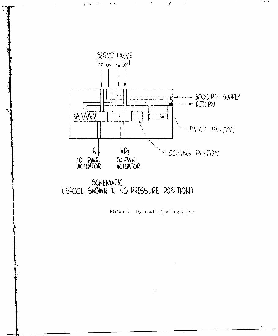
Based on this observation, a f low meter was placed in the hydraul ic supp Lvline and flow measurements made with different combination3 of joints connectedtto the supply. These measurements indicated that thet? flow was highest in thosejoints which hadt a pilot-operated locking valve, shown schematically in Figure 2.The function of this valve is, to hydCaul ical lv lock the power actuator when thesupply presstire drops below a nominal value of 2000( psi. Wh'len the specit'icat ionstor this valve were made, a minimum leakage rate, across the locking piston wasspeci f el but not for the pilot piston. Cdal1cul ations basedl on manufac turing tot-
r1ances fol thll piston clearance indicat ed thait the !-low rates measured coaild berea iiedI ais leakage t rom supp lv to ret urn across the( pt101, pistonl.
tHie hyd raIiC cpower sulyI be ingk used alt tist t. ime l a Capacity of ) .8 (GPand thet to'tal stonlbv, tor allI o! the Joints toetver wais neasured at f).85 GPI.
th~'retorl, ' he rema lniniz tow tvall able woulId notL beenug to OPer.ate 3ll theioint s togeother . tok solve tCx Problem. the S%-. em7 wats coniectedl to ;t laborato rvpower supply withl Much larger cpct. ltiuhths asavlIsoution to
thep rb erninthecae otthe arm svst, i ilntb ticln hnm -
'ltsol tHeV ITachiO I ' Ir ad ded I. The added num-.ber oI I 'ck: lng valvs, AS We011 a-sincreasedl tlow eqtrenswill mk it im"perative ~ht tee a10 rts 'reduce d, th'is prob ternl ha;S beenl solved byt ightenlilg the s'pet lcat tons Onlvalve S.
Q t -'dpr tlt. ' .r t........th 11 o Itnt is unstable At nominalI gainlso t tings kut staib I operat ion can be obt a ilned at loweril i.'
thel Wrist is the most Jointclt to sta'ilizea. th1ie laIrge \.ariat ors inncr ti a bet ween the, 10;4a10el and unloadled cond it ions make U l ditficl 1 t. to dle termi ineset oi servo parameters that will ive ktbt prtosina ~a os
Furthermo ie, the st ruc tural st i iness o t the other 1 i nt s seree t o ha%-e aI st r'nginfluence onl the stabul itv :tihe wrist i nt . 1te comlpIliance' at tilt V.ifl S't -
i ns for s tat' 1 operationwsS eprct. A Itlkougli this does not mneet thle
reqU ire-Tent of three eren it waIs dect1ded to bypass this probletn !k r thet me-ment aInd go On. I ihi s prolem and its solution are tisc skd later.)
5WQVD IALVE
30 . P I !JiP
IL I ~PILO0T P'TON'
ToPWQ. TO P~QACTUJATOR ACrTATQI
SCNEMAT !C
(5POOL 5i4OWMJ IQ MO-PQES UQE P~SIIOMJ)
8/18/69 - "Obtained stable operation of the forearm rotate but found somepositions where the force needed to move the joint is excejsive."
The response of the system did not seem as crisp as would be expected forthe loop gain measured. The amount of desynchronization to move the slave orslew error was quite large, and at times, the master made contact with the slave3.When this occurred, the operator was pushing directly against the slave causingthe excessive forces mentioned in the log.
The cause of the problem was found to be flow saturation of the servovalve.The reasons for this saturation were:
1. The slave actuator used is a rotary vane type and is susceptableto internal leakage in particular positions.
2. The servovaive flow capacity was set at 2.0 cubic inches per sec-end. Although this was probably enough capacity for normal actu--ator velocities, it was not sufficient to supply velocity aq wellas leakage flows.
The solution of the problem was to replace the servovalve with one with amaximum flow rate of seven cis. When this was done, the response of the iointwas as expected.
8/21/69 - Operated the elbow, and had to reduce the gain to get stable op-eration. Mien restarted, the wrist joint lurched and was uncor-trollable."
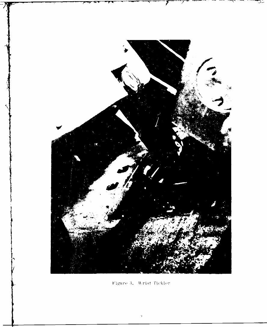
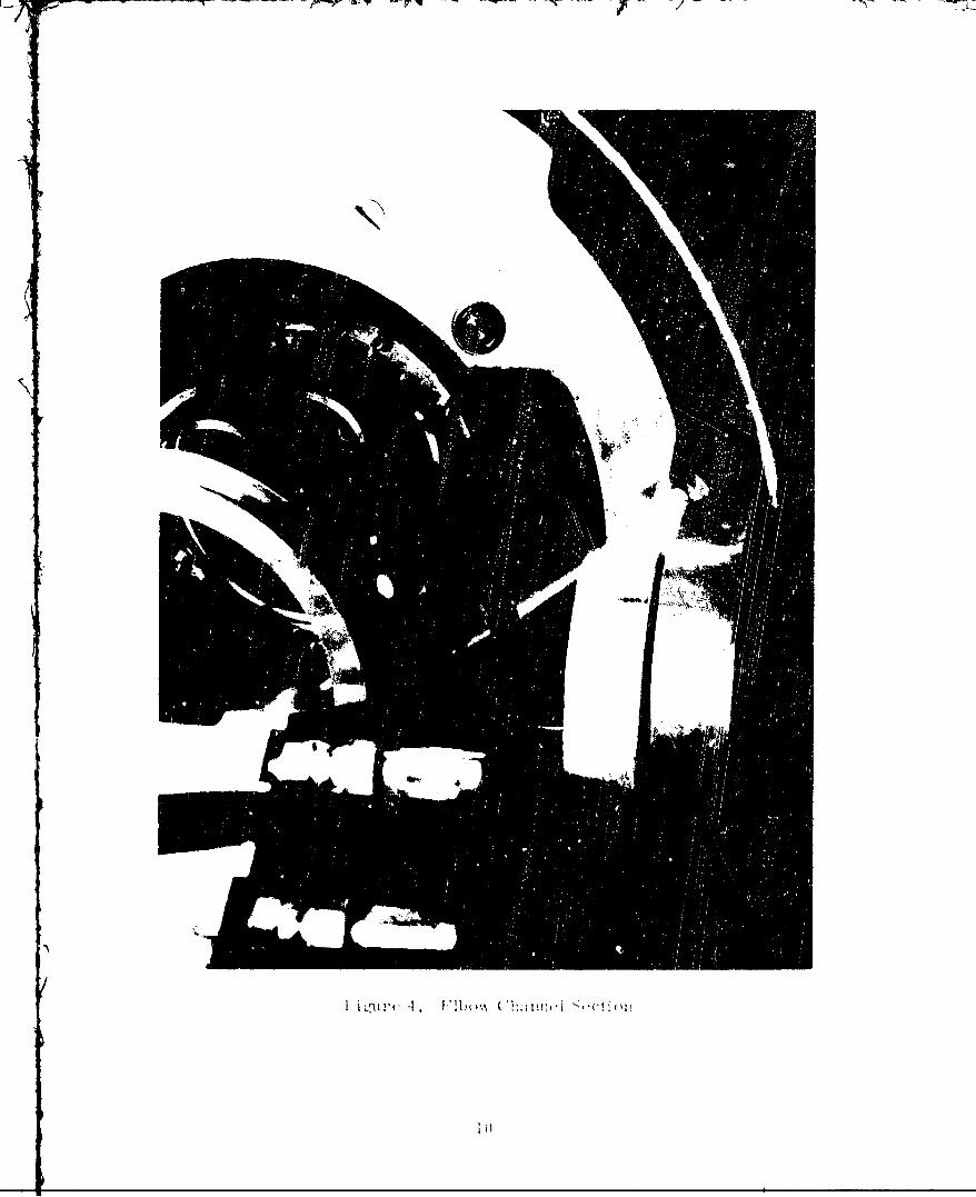
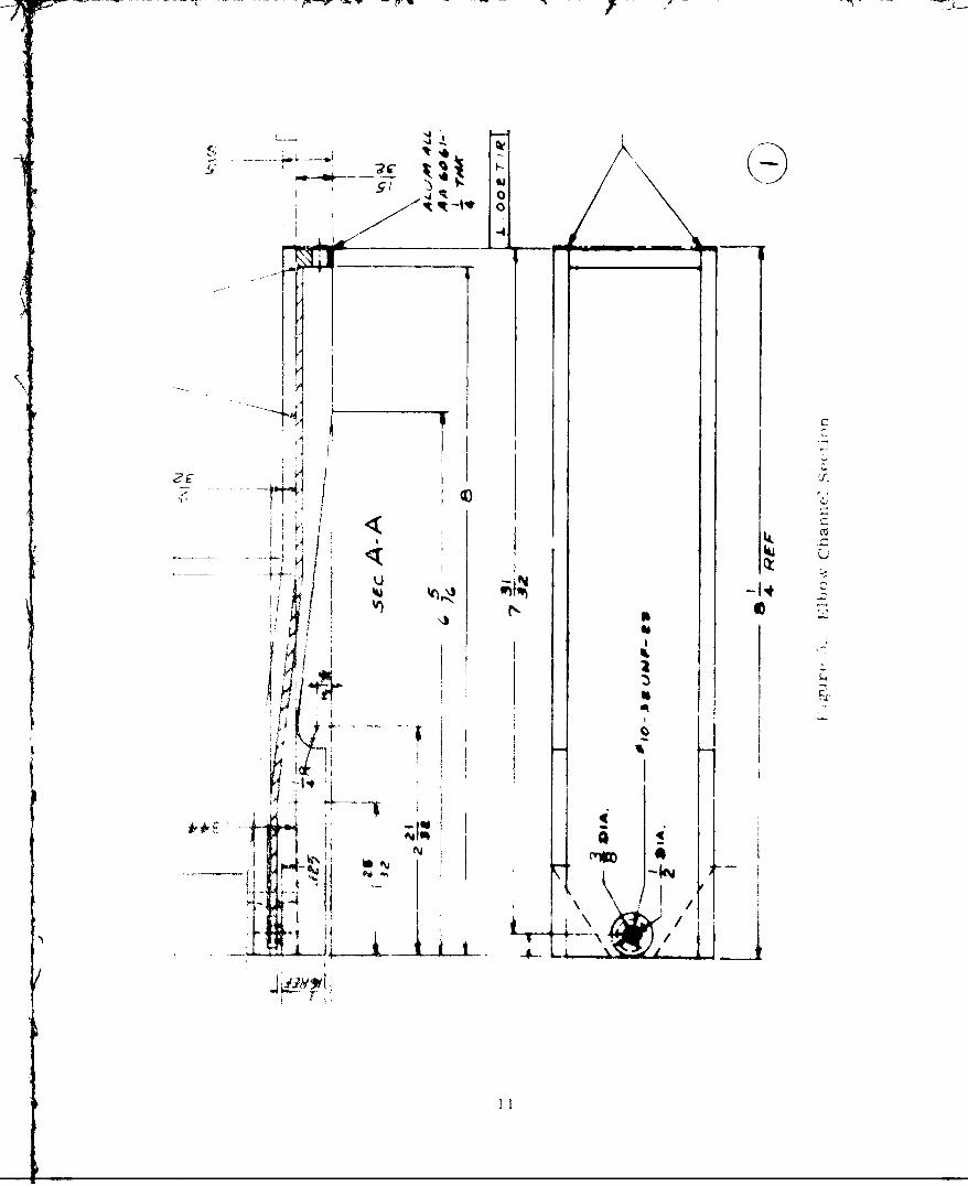
The problem was discovered to he an underdesigned snap ring-pin connectionin the wrist tickler me-hanism, Figure 3. The sudden input that i.,as applied atstart-up caused the tickler linkage to come apart and subsequent loss of control.Furthermore, a mechanical interference was discovered in the elbow mechanism.The channel section, Figure 4, wich transmits the master signal to the ebllowtickler was damaged because of contact with the slave hand.
The wrist tickler mechanism was redesigned and repaired. Ihe connectingpin was made larger, and a dowel pin and groove rather than a snap ring was usedto hold tie linkage together. 'he damaged channel section was repaired and re-shaped so it would not interfere with the slave wrist. The changes to the shapeare shown as dashed lines in Figure 5. (The elbow servo gain was increased tonominal value with stable ope.ation later in the test program.)
Q :2 0 - "'*hen the upper arm rotate was operated, three basic problemswere encountered."
1. Tickler linkage kept slipping.
2. Joint was unstable.
3. 1-hen the elbow joint was closed, the upper arm rotated counter-clockw' : and vice versa.
4%i k
N'
I i L3I ut 1 1 1 1 c ~xx (. 1:a iltP '1 'N ('! j c 'It
I U
;i 0
I i
- i I
I '
~~11
The tickler was slipping due to th3 failure of the set screws in the bossat the tickler attachment point to the master. When the part was removed, therewas found to be oblong indentations caused by the set screws slipping. It wasthe design intention that these set screws be replaced by a pin after assemhly,but this had not been done. When the set screws were replac.d by pins, theshaft did not slip.
The instability was high frequency and, therefore, the master velocity loopwas suspected. The oscillations were less severe when the velocity gain wasturned down. A recalculation of velocity gain showed that the '. ge of gainstipulated in the electronics design specification was too high. As a temporaryrepair, the signal from the master velocity transducer was shorted out. (Al-though this eli:vinated the instability, it would not be desirable to lift !,adswithout the velocity signal; therefore, electronics changes were made a shorttime later.)
The amount of interaction between the elbow and the upper arm rotate wasvery sensitive to the null position of each joint. (Null position is the pointof alignment of the master and slave at which the Joint is in equilibrium.)WhIen the two joints were adjusted so that the null position corresponded to theposition where the mastcr and slave centers of rotation were concentric, the in-teraction was very much reduced. This problem was not only a kinematic problembut also one of human factors. When the operator thought he was putting a pureelbow motion into the master, he was also movicig the upper arm rotate.
Q Q 9 - "When turned on power to operate the shoulder joint, the armlurched and the elbow would not operate."
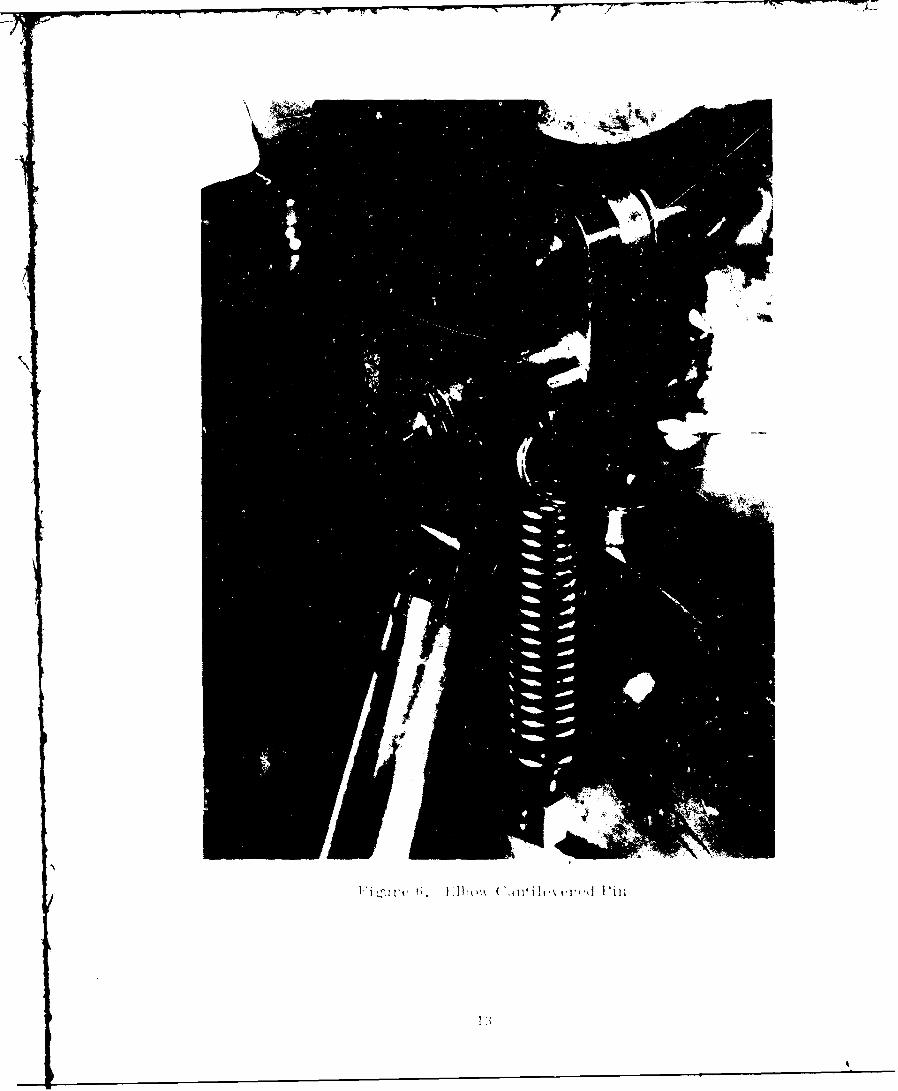
Th roughout the evaluation problm, care had to bc taken when turning ol aservo for the first: time. Each timt that trouble occurred, the master had notbeen properly c,ns trained f-rom sudden movements. 1e problem in the elbow joftntwas discovered to 1,' a long cantilevered pin, Fig.-ure t,, that had been bent.ll is pin acted Is a pivot point !or tie V bow Ii nkaIge and causedl binding i theI inkage when it was bent. Since the forces encountered were not to be expect dUnder norma op ra1 tin cond itions , tih pin was not rediesizned but merely a nowone made.
"hi e, thte new piece was be ing made, the electronics were cianged to reflectthe new spect' icatLions for the urpr arn rotate re erred to earlier. Simultane-ous t, the shoulder and back Joint> were chec-ed out anrd underwent limited o;er-at ioll. A meaningful evaluation could not be carried out wlt:out the e(11'w andUppOer arm17 rotate" oints operational.
15 t5' - "Reassembled elbow tickler and ran .ill the joints together. e ishoulder joint null position seemed to have'changed."
The operation of the shoulder and back joints is verv dependent upon tieproper null position for eacii joint. In thii instance, the shoulder ticklerlinkage was slipping. 1., cause was the same as in te upper arm rotate jointThe set screws had n,,t bten replace,! by a pin. IThen the pin was instal led, andthe shoulder and back ticklers properly nulld, the performance of tie systemwith all the Joints opurating was quite satisfactorv.
1'
I: i ~2zI Aht Ii (~ 1i1,% c'z d'i'j ll
9/16/69 - "Operated the arm system with all the joints powered but couldnot move the shoulder or back."
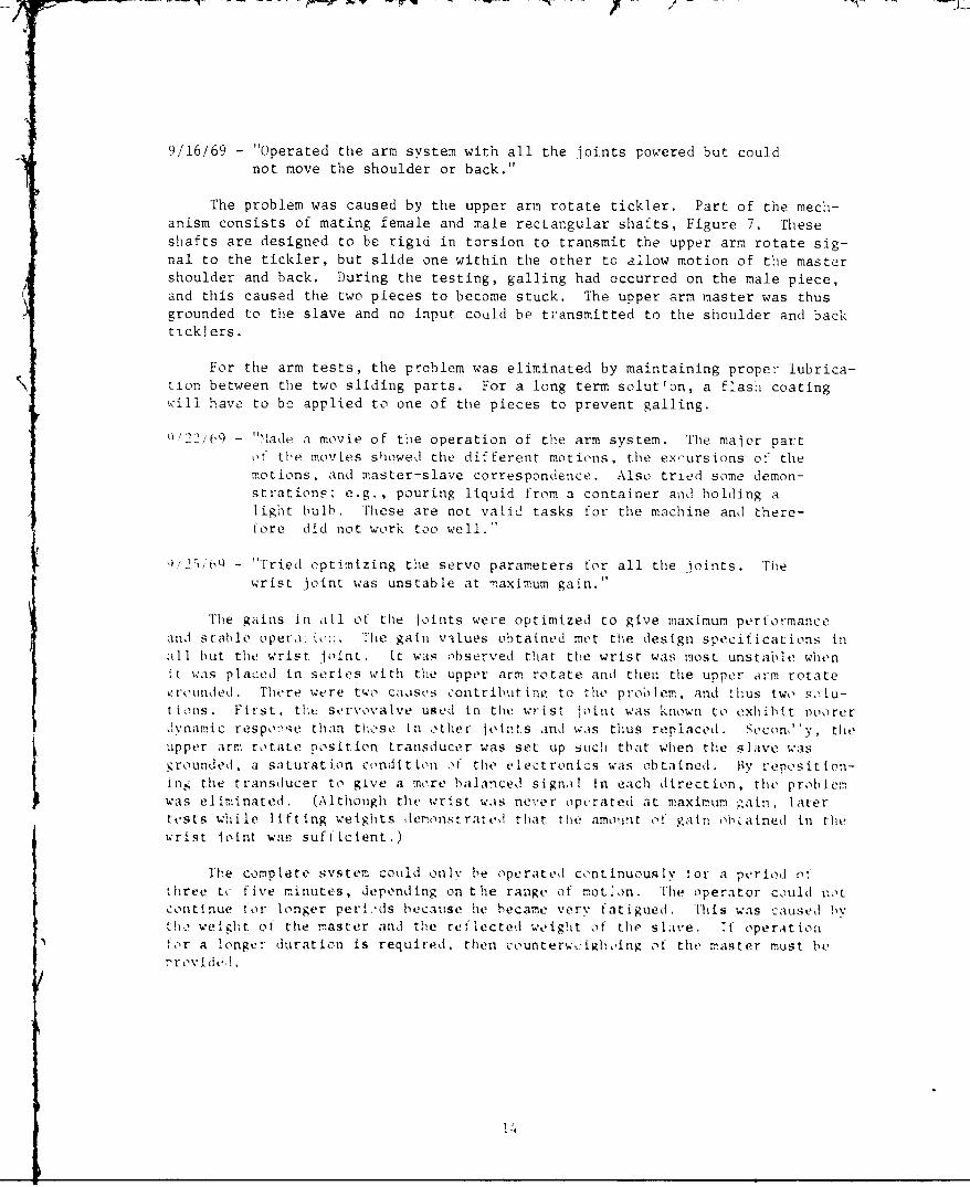
The problem was caused by the upper arm rotate tickler. Part of the mech-anism consists of mating female and male rectangular shafts, Figure 7. Theseshafts are designed to be rigid in torsion to transmit the upper arm rotate sig-nal to the tickler, but slide one within the other to allow motion of the mastershoulder and back. During the testing, galling had occurred on the male piece,and this caused the two pieces to become stuck. The upper arm master was thusgrounded to the slave and no input could be transmitted to the shoulder and backticklers.
For the arm tests, the problem was eliminated by maintaining proper lubrica-tion between the two sliding parts. For a long term soluton, a flash coatingwill have to be applied to one of the pieces to prevent galling.
22/b 9 - "lade a movie of the operation of the arm system. The maior partof the movies showed the different motions, the excursions of themotions, and master-slave correspondence. Also tried some demon-strations: e.g., pouring liquid from a container and holding alight bulb. These are not valid tasks for the machine and there-fore did not work too well."
Q2, / o0 - "Tried optimizing the servo parameters for all the joints. Thewrist joint was unstable at -,aximum gain."
The gains in all of the Joints were optimized to give maximum performanceand stable opera.io.-. The gain vilues obtained met the design specifications inall but the wrist joint. It was observed that the wrist was most unstable whenft was placed in series with the upper arm rotate and then the upper arm rotateSrounded . There were two caases contributin to the proolem, and thus two solu-
t ions. First, the servovalve used in the wrist 'oint was known to exhibit poorerdynam ic respoiqe than those in other oi. t s and was thus replaced. Secon 'y, tiLe
upper arm rotate position transducer was set up such that when the sliave wasgrounded . a saturation condition of the electronics was obtained. By reposition-ing the transducer to give a more balanced signal in each direction, the problemwas eliminated. (Although the wrist wais never operated at maximum gainl Iatert ests while lifting weights demonstrated that tle amount o! gain oh ained in thewrist joint was sufficient.)
The complete system could only be operated continuously for a period o'fthree tc five minutes, depending on the range of mot'on. The operator could notcontinue for longer peri.,ds because lie became very fatigued. This was caused bythe weight of the master and the reflected weight of the slave. 1f operationfor a longer duration is required, then counterwr:i'gh oing of the master must be
/ ,r rovtdel,
11
p - -
Figrill-1'- 7 p-l
10/3/69 - "Operated the machine while lifting 125 pounds. The followingobservations were recorded.
1. The machine responds to inpu.s differently under load andseems Jerky.
2. Uncomfortable contact forces at the wrist and upper tcrearm.
3. The grip required to close the thumb tip and thumb flexaffects the performance of the other loints."
The first comment has to do with the fact that the machine responds to aninput in the direction of gravity faster than against gravity. This is to be ex-pected and is not much different from human response when lifting weights. Afterthe operator practiced for a tew minutes, he became familiar with the response ofthe system, and the operation was much smoother.
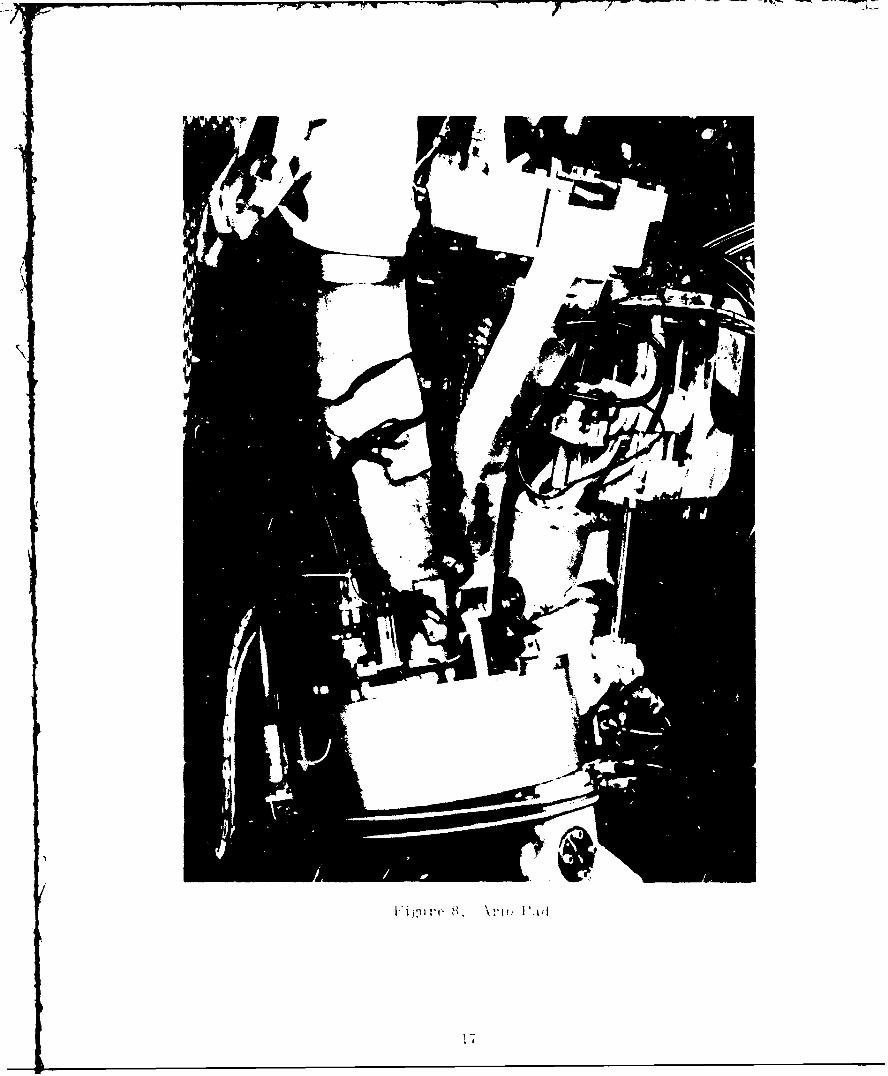
'The discomfort due to the high contact forces was eliminated t,v usini alea,-ier arm pad shown in Figur, 8. This is similar to the ring-pads discussed inReport S-t,7-1011, Page 18.
['he problem with the grip was that wh;en the operator a-plied the forces re-quired to close the thumb loints, his wrist and forearm muscles became tight, andhe could not apply full excursions into the master. This problem was also reducedis the operator gained experience, and although it did not limit the per formanc ,the hand grip configuration will be studied for possible modificati, rns.
10' " - Lifted 2750 pound weig'ht using 'A' frame and tether system."
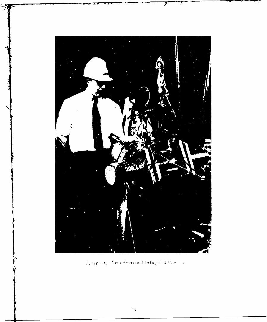
Figure ) shows the arm, system lifting the 200 pound weight plus 50 pounds ofr- I g ginmg.- The frame wo rkin the backgroun' is used1 to suppor t hei it wh t- : acts
aIs $ t: tiler and als, han- d Is the we ighUs. I'he operator is we:irinlg the 'a-! h.it
as ,,normal operating procedurc when overh;,ad equipment is being used.
'he weith was .aise, t.- height -'' six !eet anu in general was . andled,asilv. Vi' operator was ,t ,. to hold the weii'ht ,or a ,reri,:oi ab,,t one an,:one na if :inutes. this was lited hecause the operator was o0n.: n t ,'tr In,;reachin. out when liftin) the weicht an, there?,ore exCrte, a rtat deal 0 ,cr :v,,..en th:e leg svs em 'sadd. mh Wil this wIll He eliminated as( th, swilm[st of the lifting, and tile operator will be able to keep tl'e weig.t in c.cr
to hfs body.
" I -'I.1 fted the 31 pound test we ight and a ,so workel the 1 n oun.;
weight unt ethered .
Figure 10 shows the weight usid in the rIn' round test. :Durini: '
m.achine was abl1 to li't the weight about a foot and a hal: a.bove t he ros t on-n the picture. ihe 1i'uitinz factor in lifting tihe weight hiigher Was not th, .-.a-chine but rather the strength of the man. Aga .n, some of the problen can be at-tributed to the tact that the legs are not 'eing used, but in this case, itseemed that t!e force ret t- the .rator was too great f,,r him t,, over-come.
1 ti
eI
E$
, (J
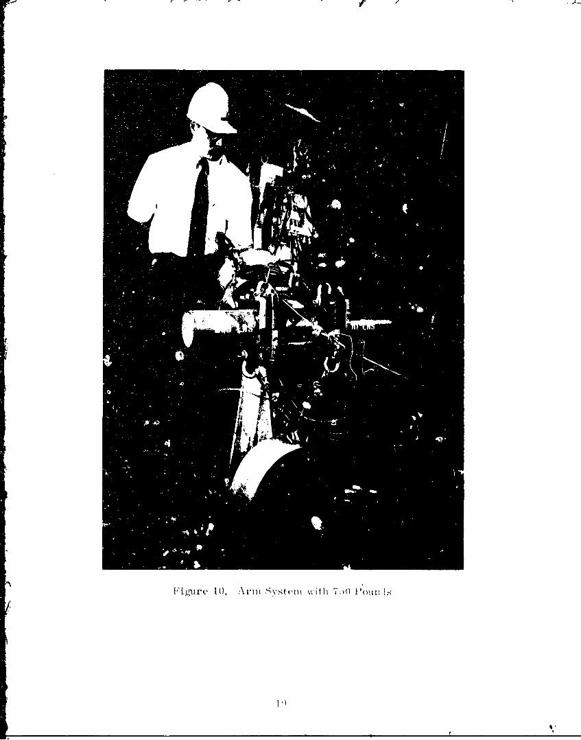
Fig1Ltirc( 10. Armt] Svstenm %%ith 7.)0 P u)fli
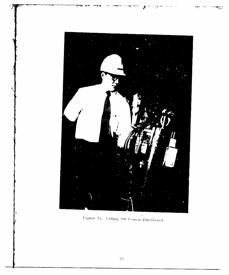
In Figure 11, the machine is shown lifting the 100 pound weight without thetether. In this position, the gripning force of the thumb is strong enough tosupport the load. During this test, the weight was removed from a hook, held inthe vertical position, rotated 900 to a horizontal position, rotated again to thevertical position, and then placed in a circular tube.
10/16/69- "Made a movie of the operation showing the machine lifting the100 pound weight untethered, the 250 pound weight and 750 poundweight."
20
ri T l t e
APPENDIX I
APPENDIX I
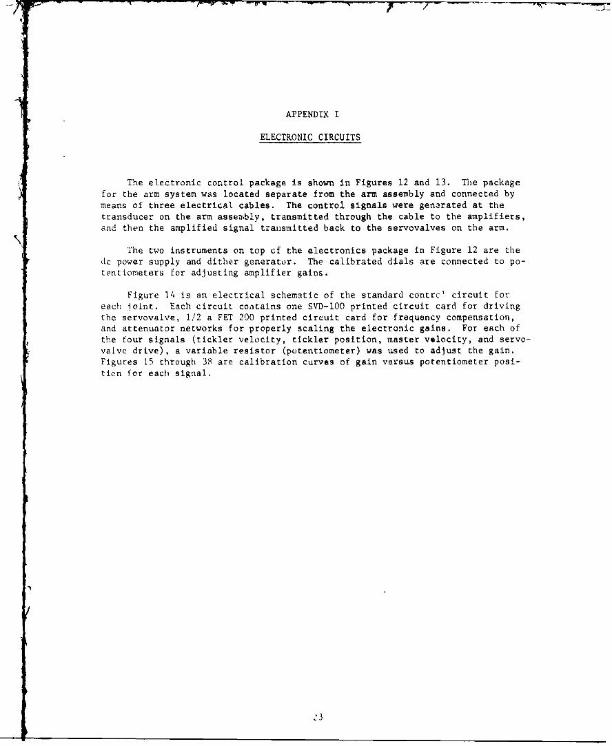
ELECTRONIC CIRCUITS
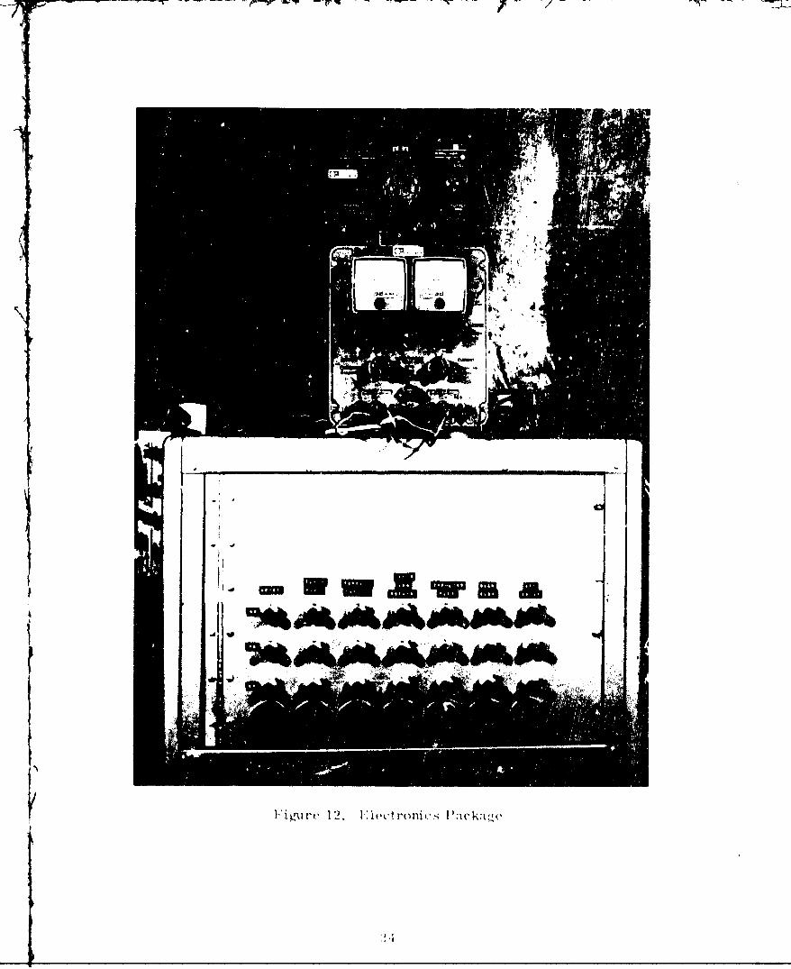
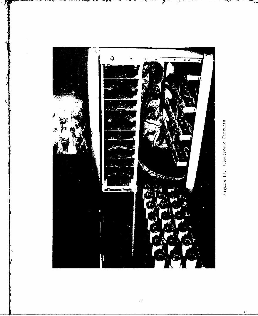
The electronic control package is shown in Figures 12 and 13. The package
for the arm system wss located separate from the arm assembly and connected bymeans of three electrical cables. The control signals were gen3rated at the
transducer on the arm assembly, transmitted through the cable to the amplifiers,
and then the amplified signal transmitted back to the servovalves on the arm.
The two instruments on top of the electronics package in Figure 12 are thedc power supply and dither generator. The calibrated dials are connected to po-
tentiorieters for adjusting amplifier gains.
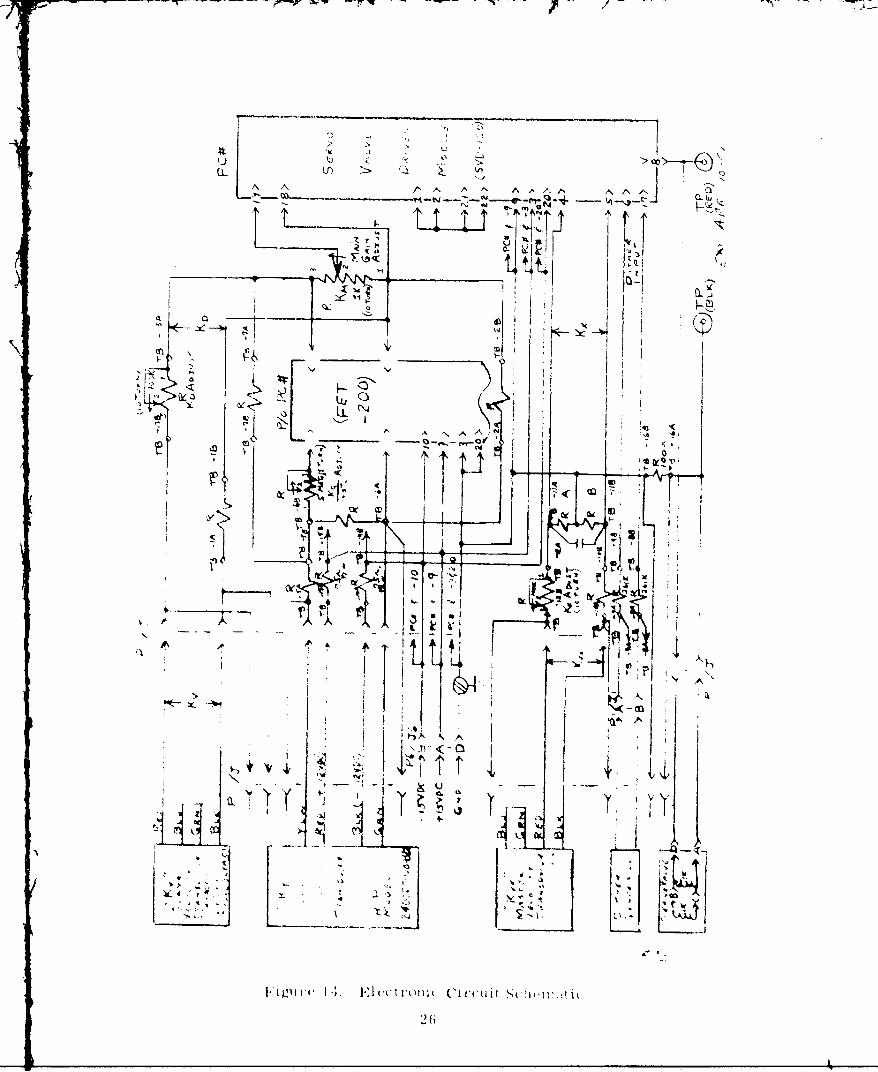
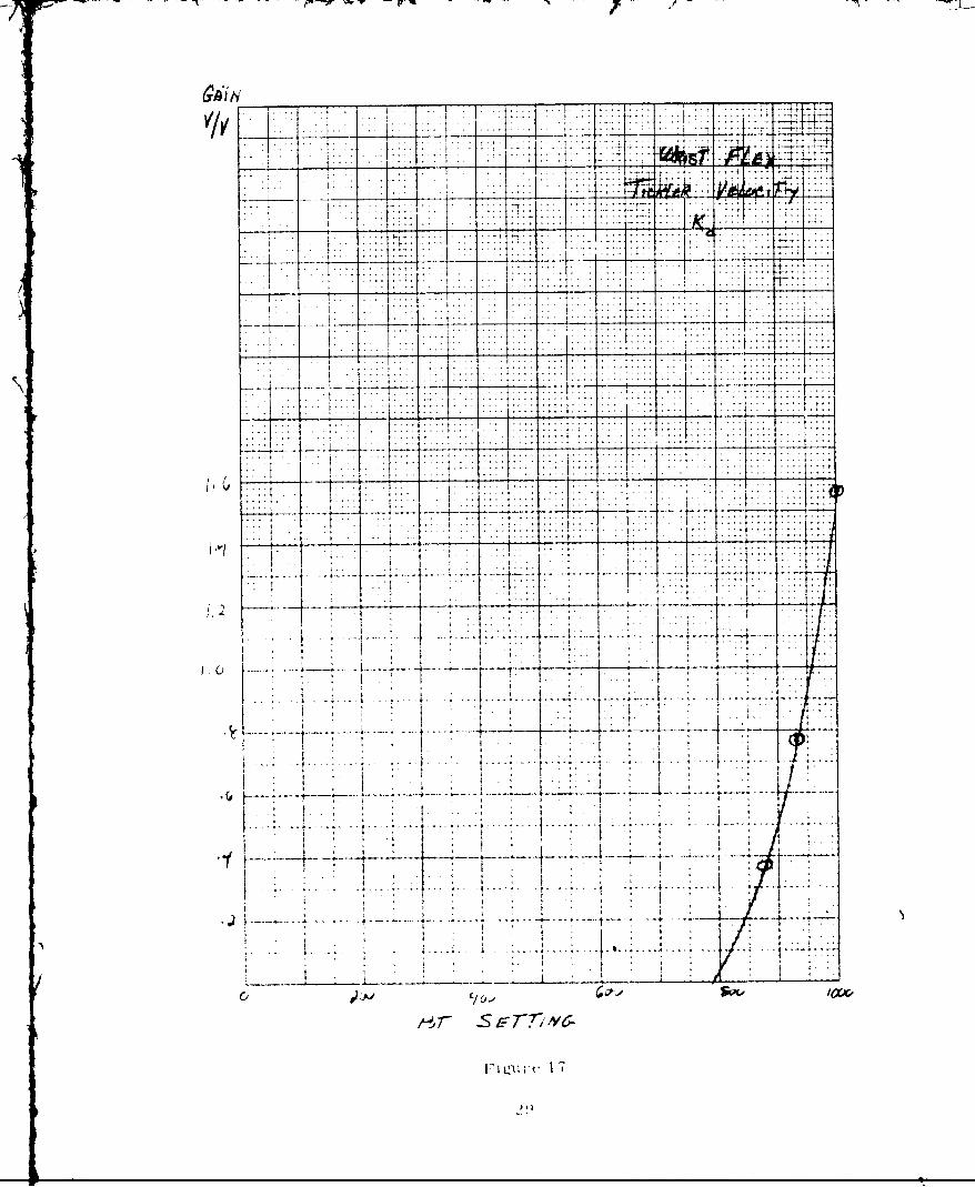
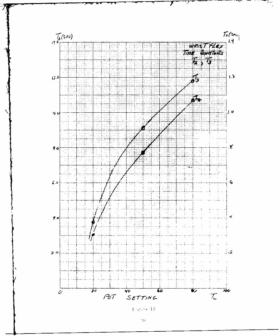
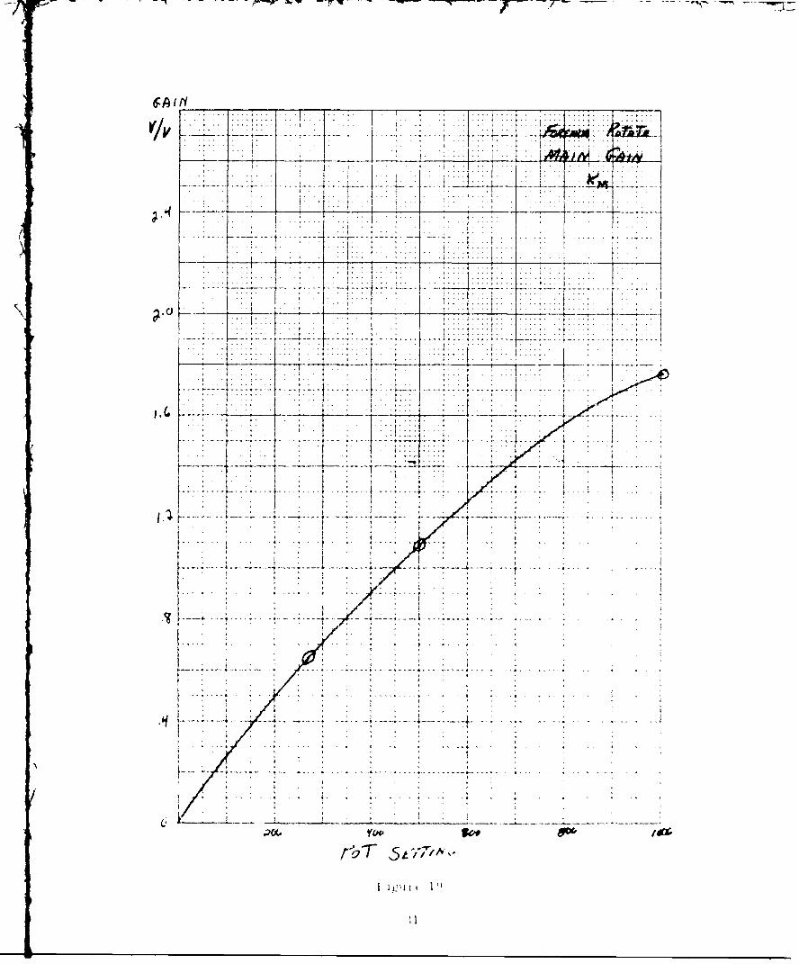
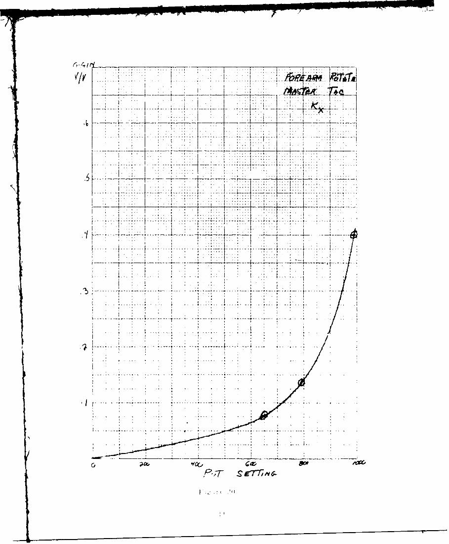
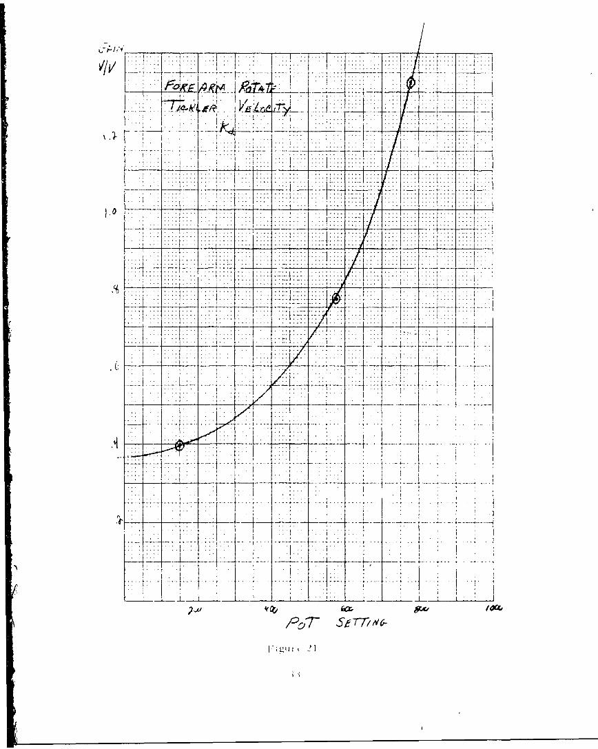
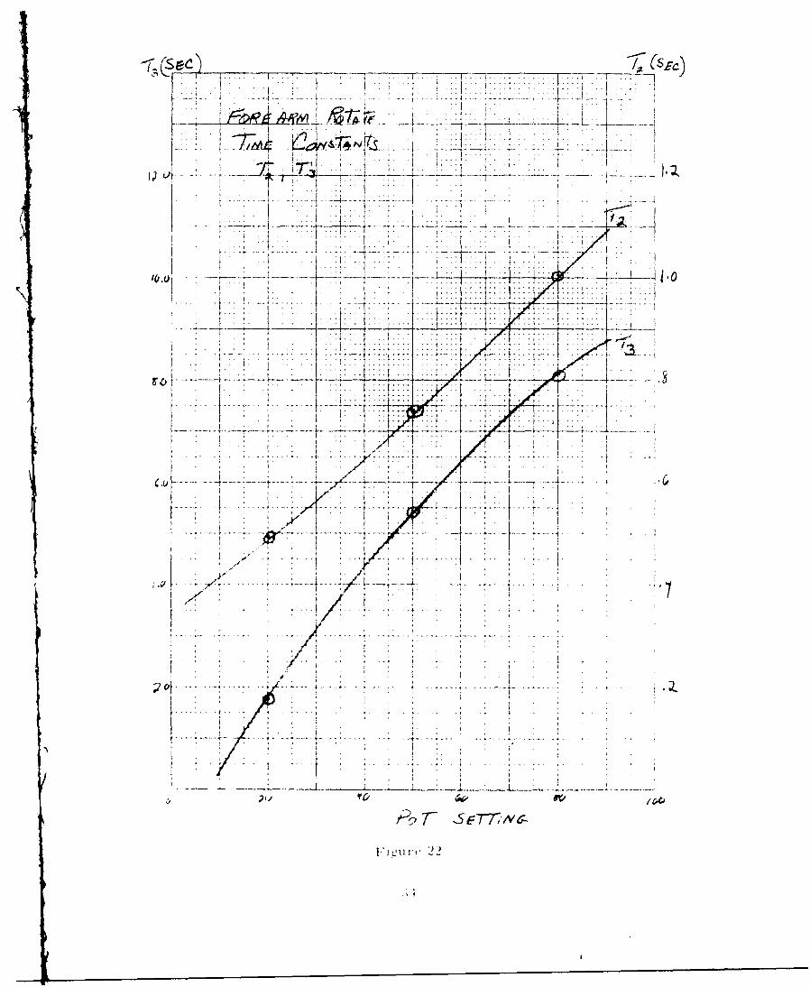
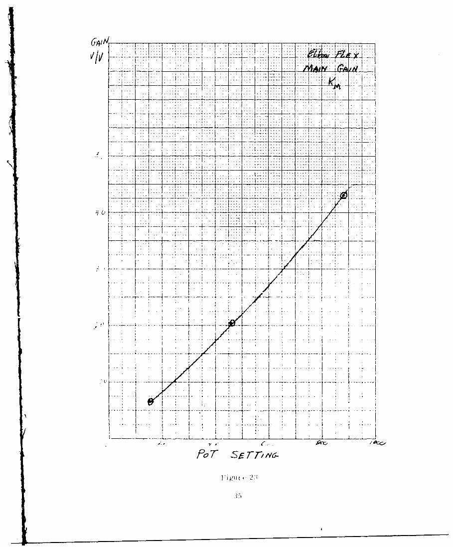
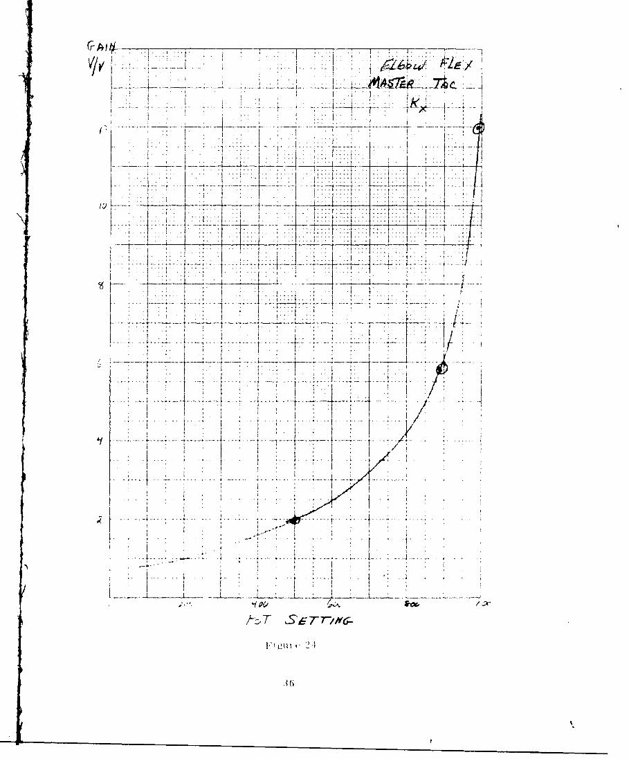
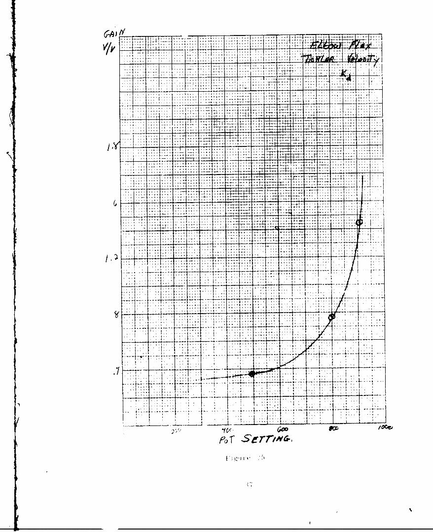
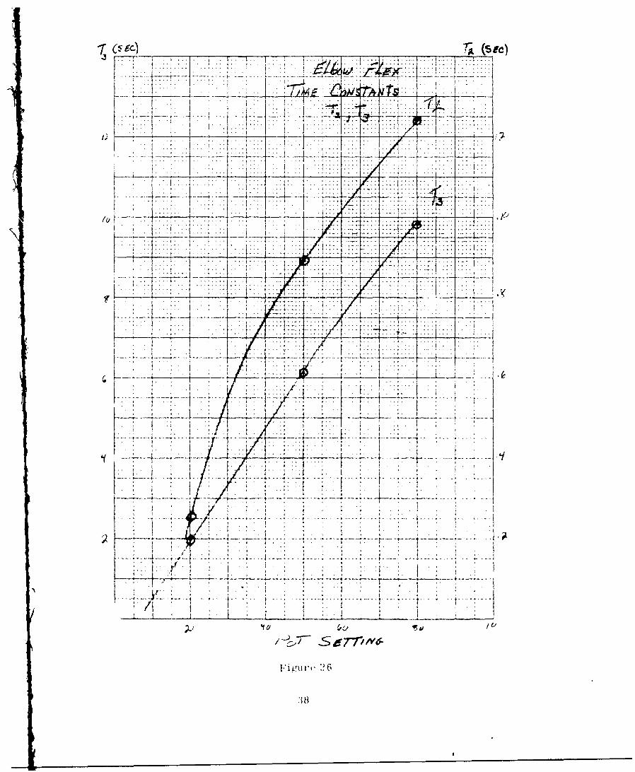
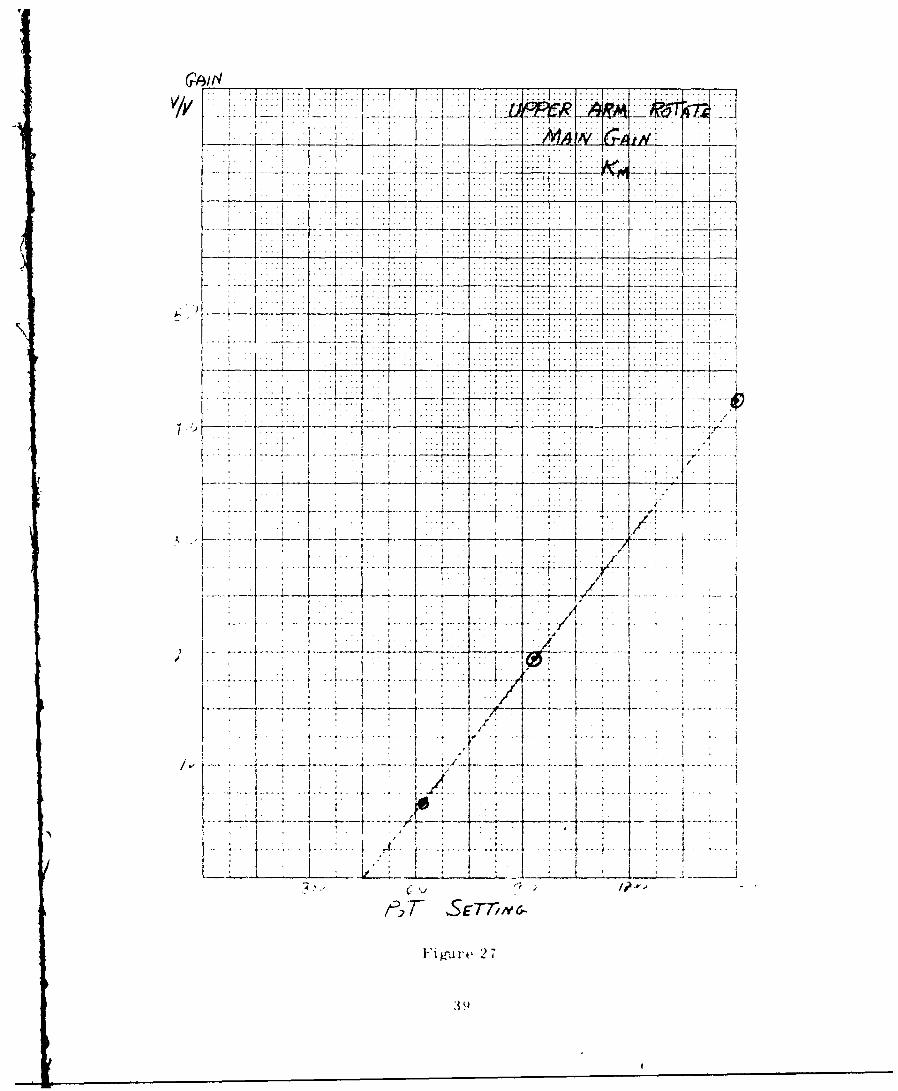
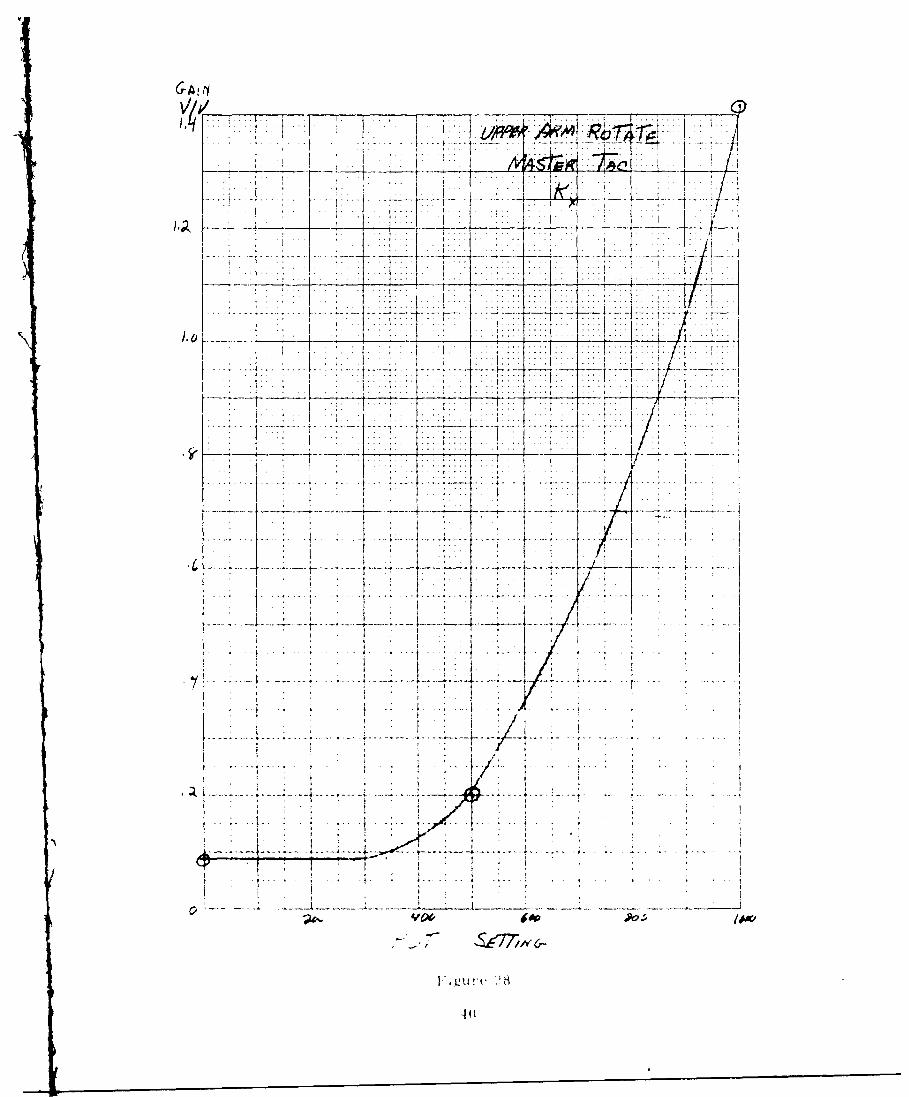
Figure 14 is an electrical schematic of the standard contrc'. circuit foreach joint. Each circuit contains one SVD-1O0 printed circuit card for drivingthe servovalve, 1/2 a FET 200 printed circuit card for frequency compensation,
and attenuator networks for properly scaling the electronic gains. For each of
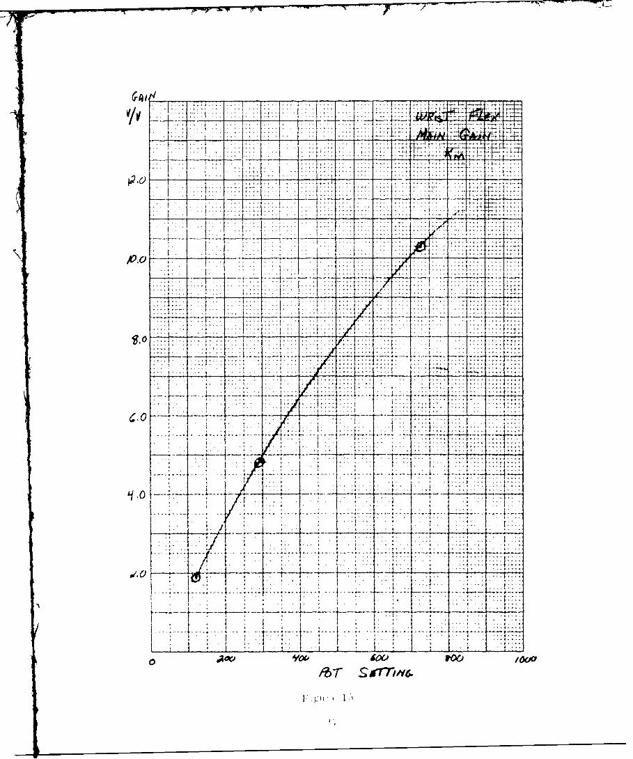
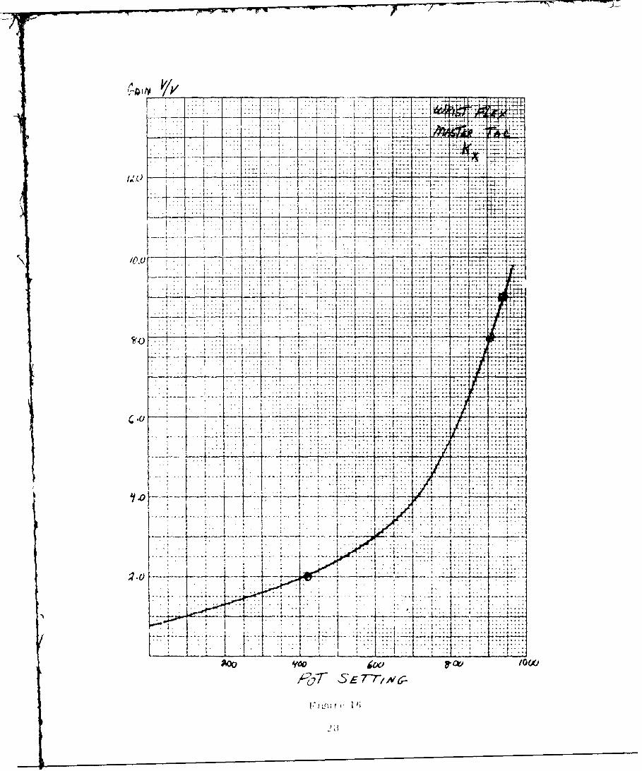
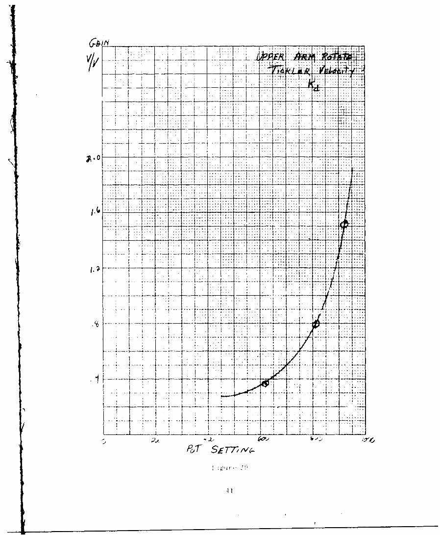
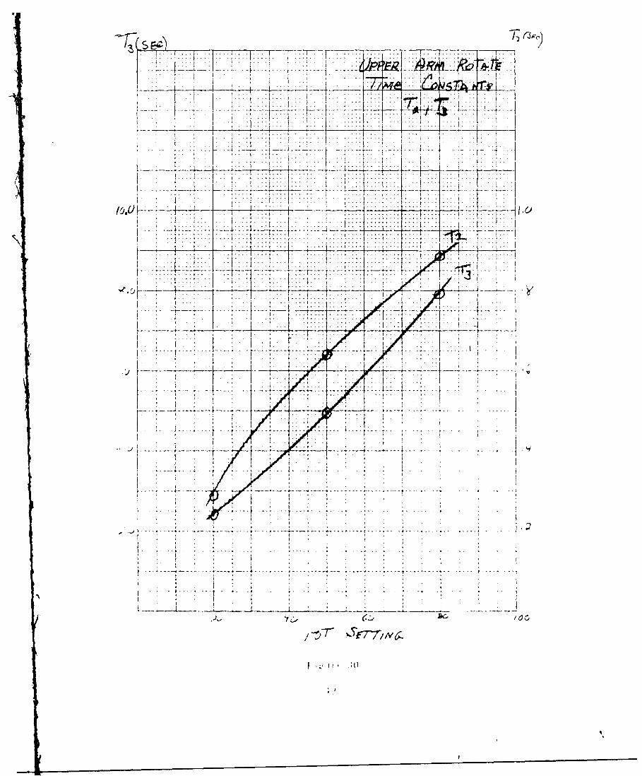
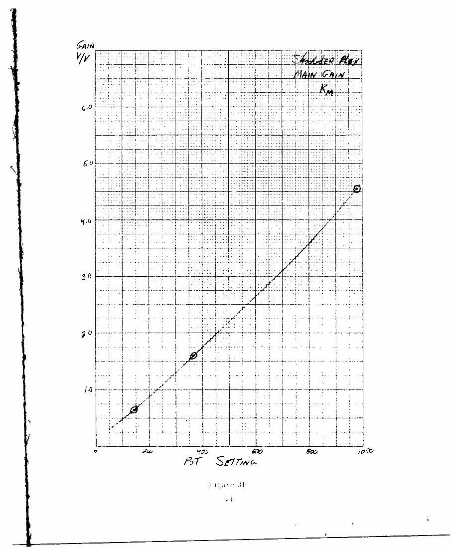
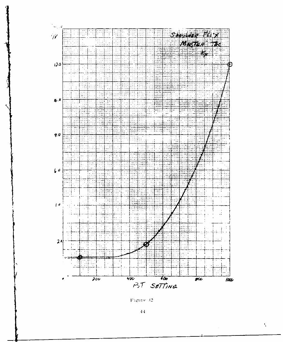
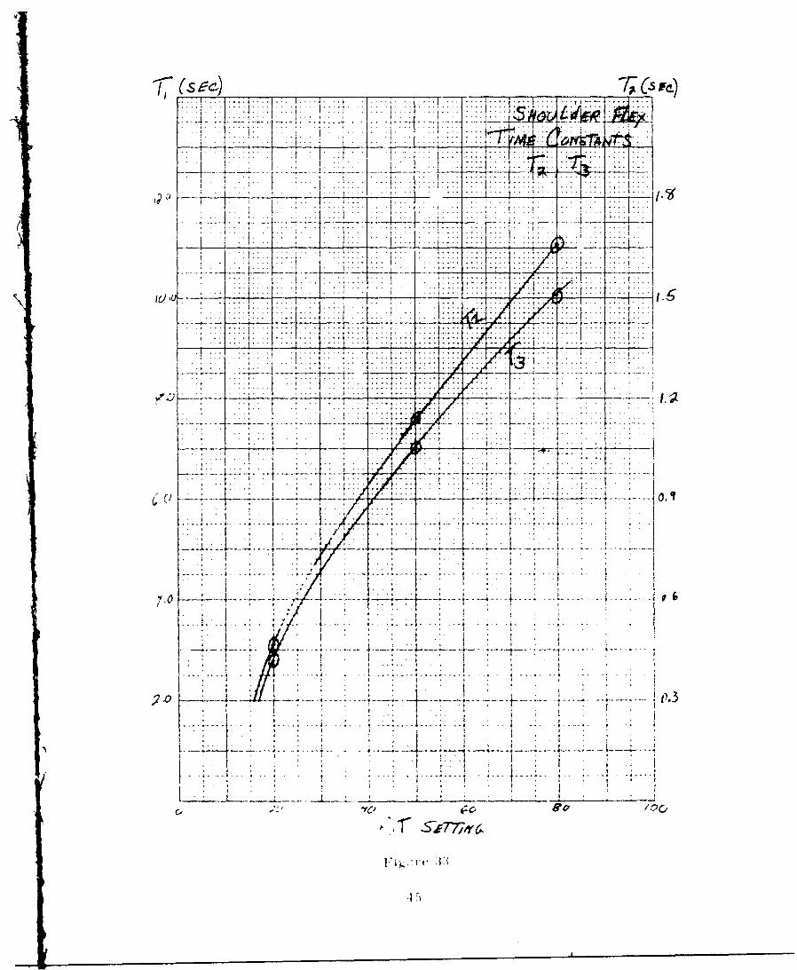
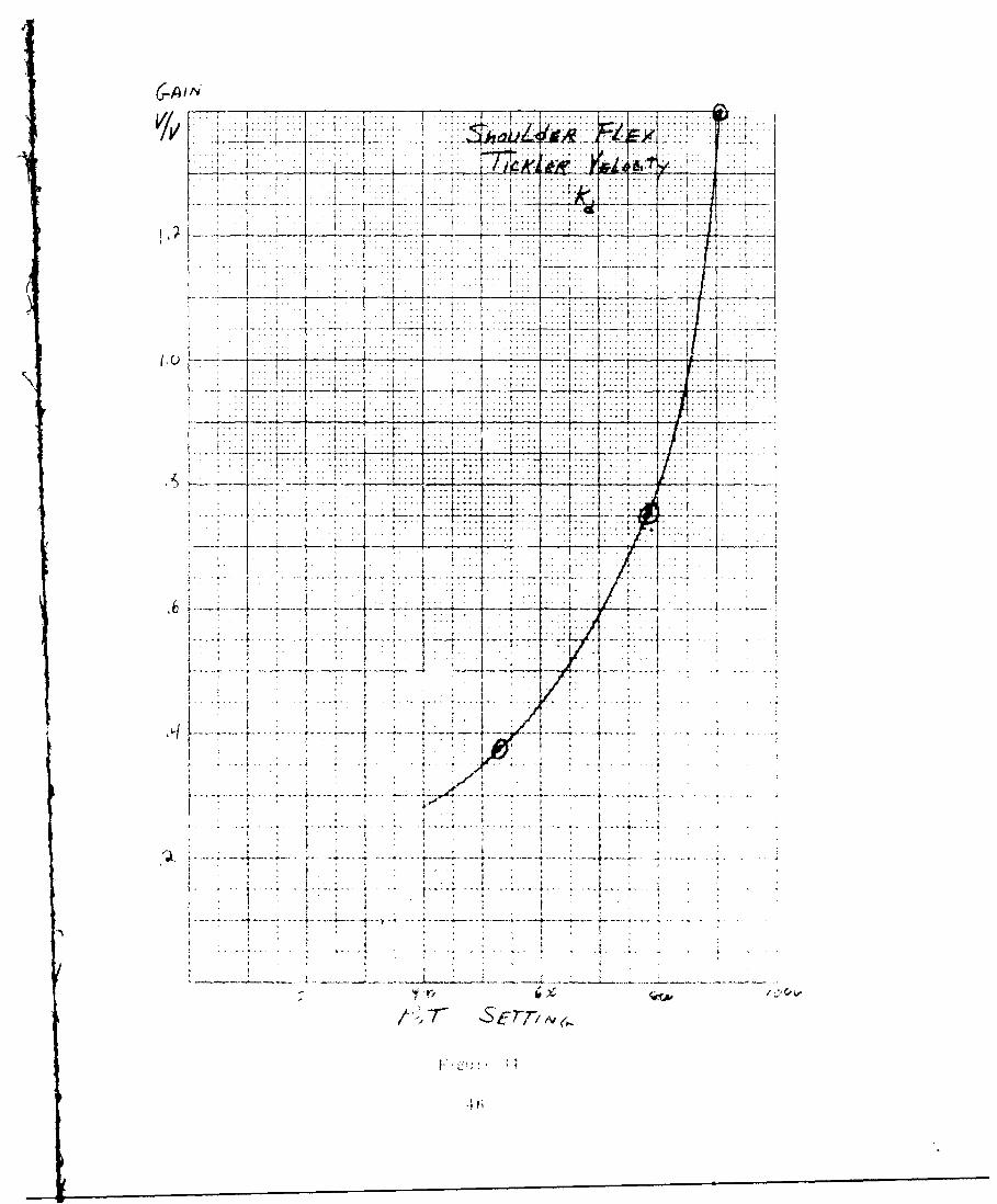
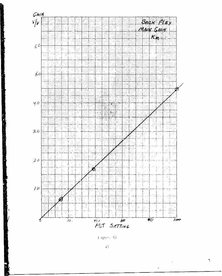
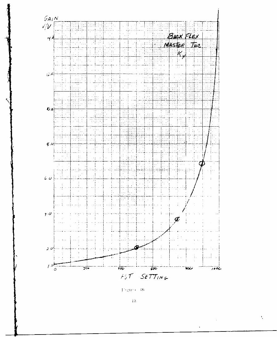
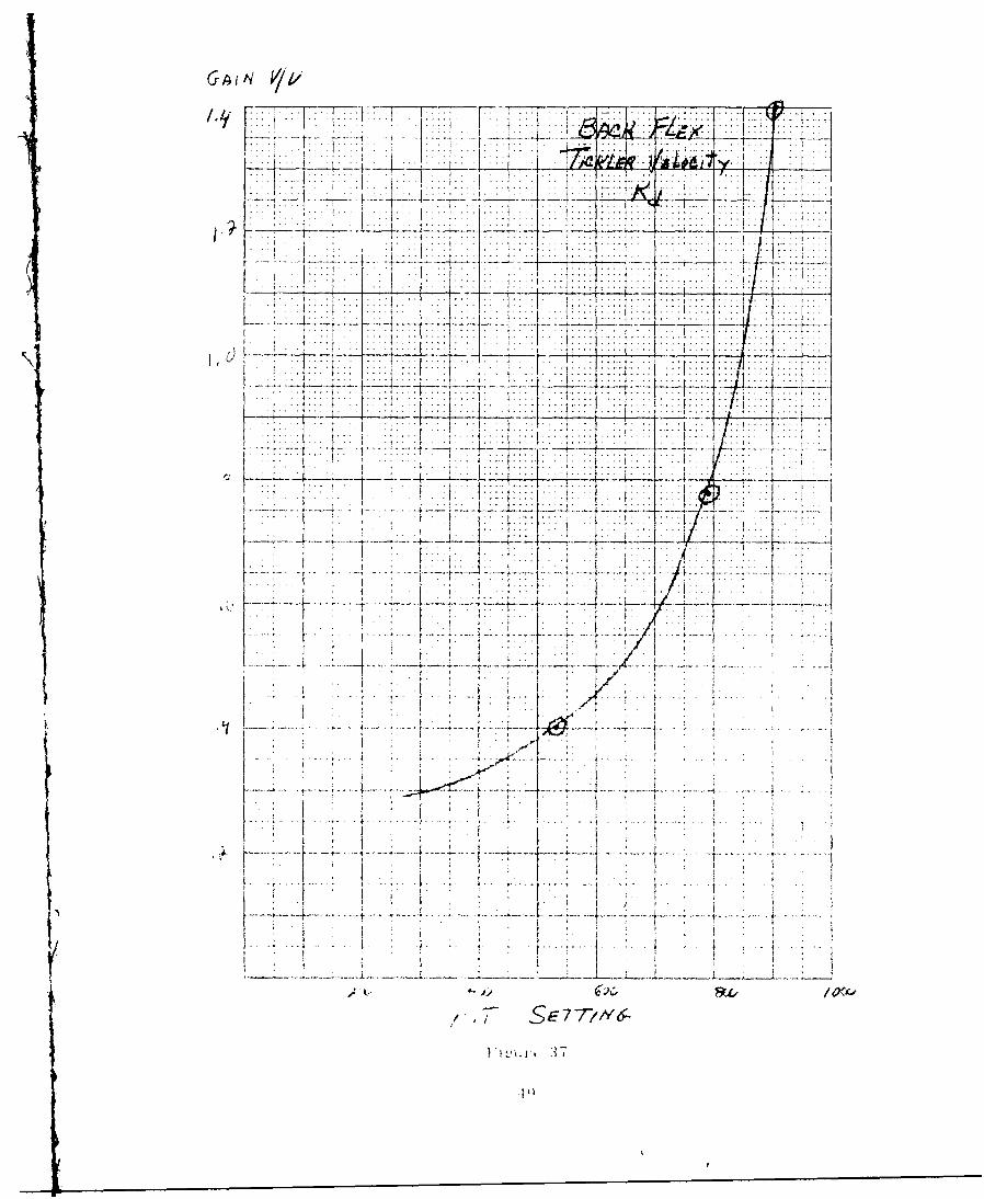
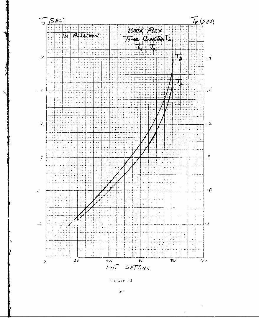
the four signals (tickler velocity, tickler position, master velocity, and servo-valve drive), a variable resistor (potentiometer) was used to adjust the gain.Figures 15 through 38 are calibration curves of gain versus potentiometer posi-tion for each signal.
23
F:igir 1 ~ 2. 1-i: otronics I a;c kA
-~--- -,.------ ~ 7 -- In
TIC, C)
U4
G9UW*Ma WAS
>~>
L k
z <of_ _ _ _ 1 t cc
o"
'1'
-
(Li 0
____26I
qT m
7- - =,
v:1
- 7 - ---7t . - 4
. . . .. ..... ... ..
7; . :
.. .. . .. . ..1~
...... . ...
C. 0~
... u $. .. .. .... .
1b77
to
-77 .T
... .. ~.. .. ,
*' - -7 - .. . . ...
. . . . . . ..... ..........
SE. 7-r/C
. . . .N - " - - - N- - - - - 7 - -
77 ........... ......... ... .': -- -i-.: j. .. '.... .... '....... : - :.... -
. . ... --- -- - ' * .
t . .1:7~ -7
2 11..
. .. .. .. .......... ..i ... ... -- - - -. + . ... .:' -1
I . .....
.... .. .. .: .. .. : -... i t :.. :. . ..:. . .... . . . .. .
!. 1 . . . wfi , --
i ... I , , , - ii { 4.....
F'i u'' I "7
I 1 :1 .t
.. ... ........
... .....
. . . .....
.... ... .
4.0:
.. ... ...
.~. ... .. . .. . . .
l'o'T 4.. serl.
-1 -1---u- -- v-F-r -- ---
1A ... .. . ..
1.w1
a1 q
...... ..
7 --
4
.. . .......
4 . ...... ...... ......
r
g-4 1 7' . t:.ii.,, t I 1
I t
{ .<... i:~ ~ _____
-1*1-I .::
4 -*~ .!..~ ..........
.1..
I."-.
:4) i4i~~...................................................................................................................
I ,........~ .,.
:.t7.T<~~77§7V7~I ~ ~:f7rPc7 [
4-'I- t ,-.~.."
-j i.j~ p.::.
:75? I..'
I.* . t
I . .
..........................--~.p.-....--,-.., ..................
It...........
......................................... ~.
0 ~. ~----.
~ SE77N6-
--/- ---~*+r~ -----
7-r 7A --
1/jc 2 ~~I ---
..I:: ..... .a m
[7-
~~.. ......... .
77.
-.. ..4 ...
~.121
... . . .
.. .. . -7 : -- 17
i.L
. . . ....... ;z.......... .. . . . . . . . .
V.1.. ,..
( ql I ii .I - I ..i. ..-- - - ....T -- ... v. ...
. .. .. . . .
-7 7w ... 7.. .77A-7771
.. ... . .
*~~i 7-{ r/- -
* , /LL.~ -~
'IV -- -.--.- ,. , ~ "s..cp.I. ,.. I I~I--jt+ .> ,. I
................................1711'I ~..I . * .
-~ ..~j-tj....1.iT.
V. f .Ki..4.7>2.J T ~I .~
~ 2
I _____
K1±.ii2IihiilYl 4.2 -~ ~j /~i 2
. L:..:...:..i 4
t .
* 77~7* .. ~ II
'1 ,K"i~ ~,. i..j2.
t. .1I I~L. L.L .~.L. zJZL..~. .. ~----.
/-~.T SETT7K&
IIL'LU 2
~ ()
CA /Y ... ...TTT
.. . .....
... .... .~. - Z:T
.~ m
17
71. 7 - -
. -
--- I-.--=T
-4 TE77T
itt1~ :4mm
-7t= - I
7.,...-..
t~-......
I ~. F.7:7-.
ly C-o
I ' .. .....
-~!. ---......... ~.-
" " . * i .::
........ 17...... i- V ji -i ? 1 F
..... ... -:!!......... ... . . . . . .
I' a ... . . . . .
.. . ... ..-... . ."'/ - -- *-- - ... .. .. t I . .: -"? . . . - -t--'- .. . .. : .. : . . . .
. a . - -,
! .. . - . . .. .. , a
LVI 4 ] . '1 ,/
.tf , : , t
I,"i .u , '
:! .
>jt14~71T E6-
-- -- V -.-- J --- -------- 1-
. . .... ..
.3 P
,, ! .-. . .- --. -- --- - -
I ..... ..777 .. T7.. -'T.-!:-:ii , .7717KI .....
;_. 4 ; 4- 777 . 7.[
i '.. .. . ; .
... .. . , ....... .... ... ..-7 --.... ."/ i * ...... . .. . .
! t : ; 1.. . 1 , ..
, , . l . , . I !
I , .... '
, . .- .
....... .. ... : ... .. . .... 7 . . .... . .. _ .. . .. .. . . .. • .
A ; - -- . ... ... ... . . ........
1P1
_7 -19 21
.. .... .--
... .... .... ...
, .. . . ."
_ _. . .. . . ..
.. .. .. . . . .
.-- 7-7- -7..L:
7-77-77
± , . -vv
1--a- f ------:-------
....... f......
7f77~--
.7-7
..............
*, r 7-7 1v
0 1~ 7 7 77T-7
It,
7V:
G0 4 4 4. - .... .... .. -.--
. ......
.... .. . .
7/77
* ~ ~ ~ . .....,. rT j .... ...
.. .... ...... .
.. ... .. ...
... ... .... . . .
~ 7 1
IF 070. .O sex . .
*~~ t. -. . 32*
.44
V7
4[4
721-L i7
7 -7 -7 7~ -4 --7
ILL7
........................................
7,tI0
222..1. I>... ..... .. ..
.. . ~~.... ..... . . ...... .. . . .x
77 1 1
7 7 -r-- -77
., , y.t
. . . . . . . . . . .
I.-..7-T
2777. I K<17-,'v ........ - v _ L_: ii~~~i! !: ..: : = ':': :
7777ii 77 I 1:L.
H4 '-7-<-
" . , ... . :--::. - ... !-il i i -
- ... t• -- z {. . .. ... : ...t i :: - : : : " ::: I : I : . ... .
,2,O 1 , ::::.. ... .. ... .... :. - t ......... : ...... .. ...
*} 1i .... .t i .. ,*:L .. ... .. ..
: i : [ : : : : : : .i*i :
/. I -:- T : ... i :.. . .. ....... . .;. .. .. .. V...j
'I . . .-. . . . ..... . . ..- '':.. . . .i... .t . . .. . .. 1... ! :
! i4 4... :.._ .17_77_T . I
itl. ...... .-
iI
7t:
77 . ..j.. ... ... ...~
.........
0 o--
____ kz~ih7tiiv 21L <
-7, p t 77.. .... 4.
L4 77+7 i4<.
lott
I..
:-7T-.77777 7 .. ....
J: 17-7
_w . IL
/~ T/ S7>6-
4i X.
... .... ...
77.. .... .
IFT :i74 .x1
FT * . ..
::j:
77 -
APPENDIX 11
APPENDIX II
SERVO PARAMETERS AND CHARACTERISTICS
The configuration for the servo control system is the same as was discussed
in Section 6 of Report No. S-69-1116 dated July 1. 1969. The values of theservo parameters which resulted from adjusting the electronic gains to optimize
the system are given in Table I. The servo performance in terms of slew error
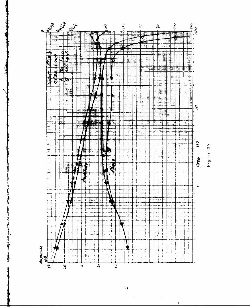
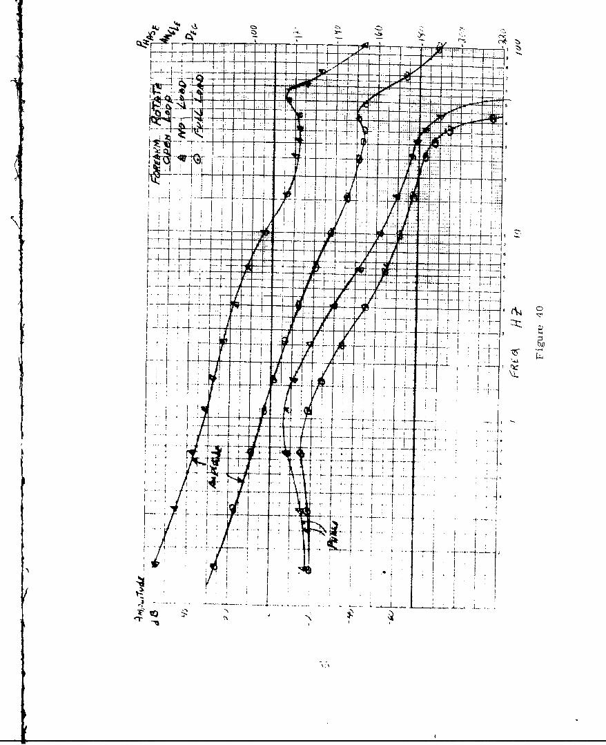
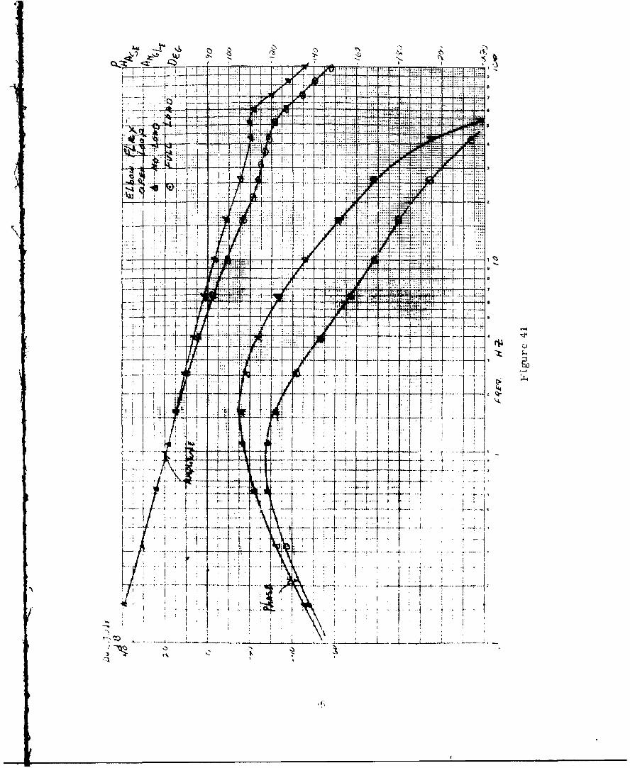
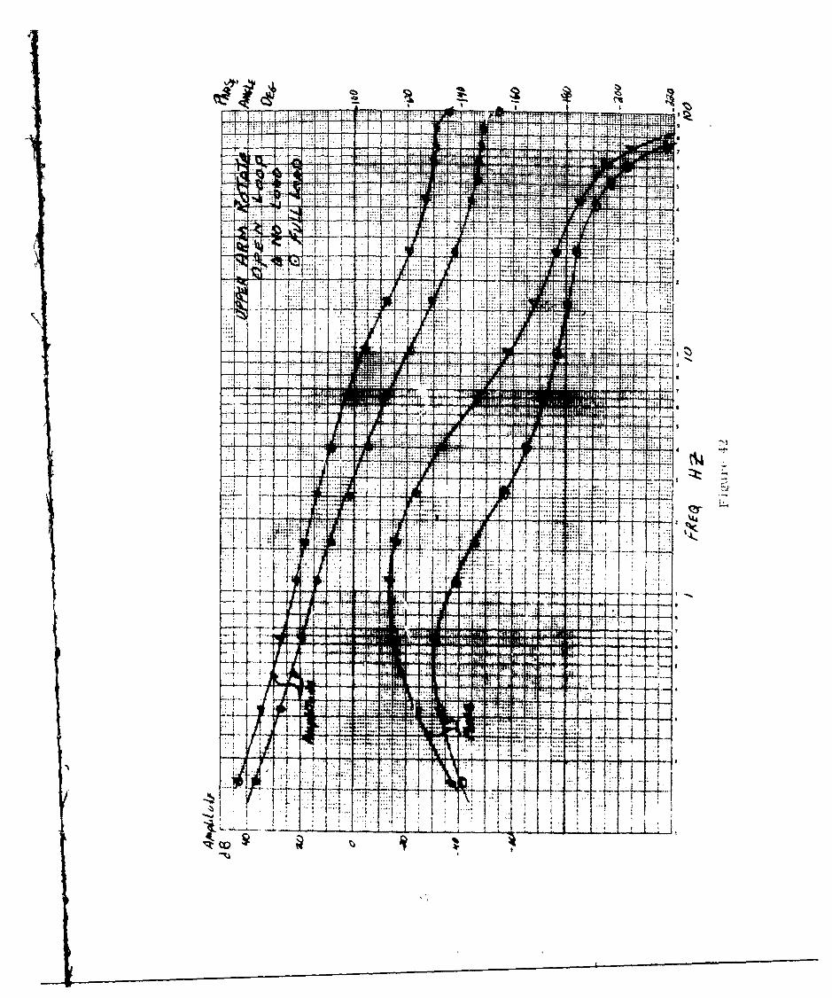
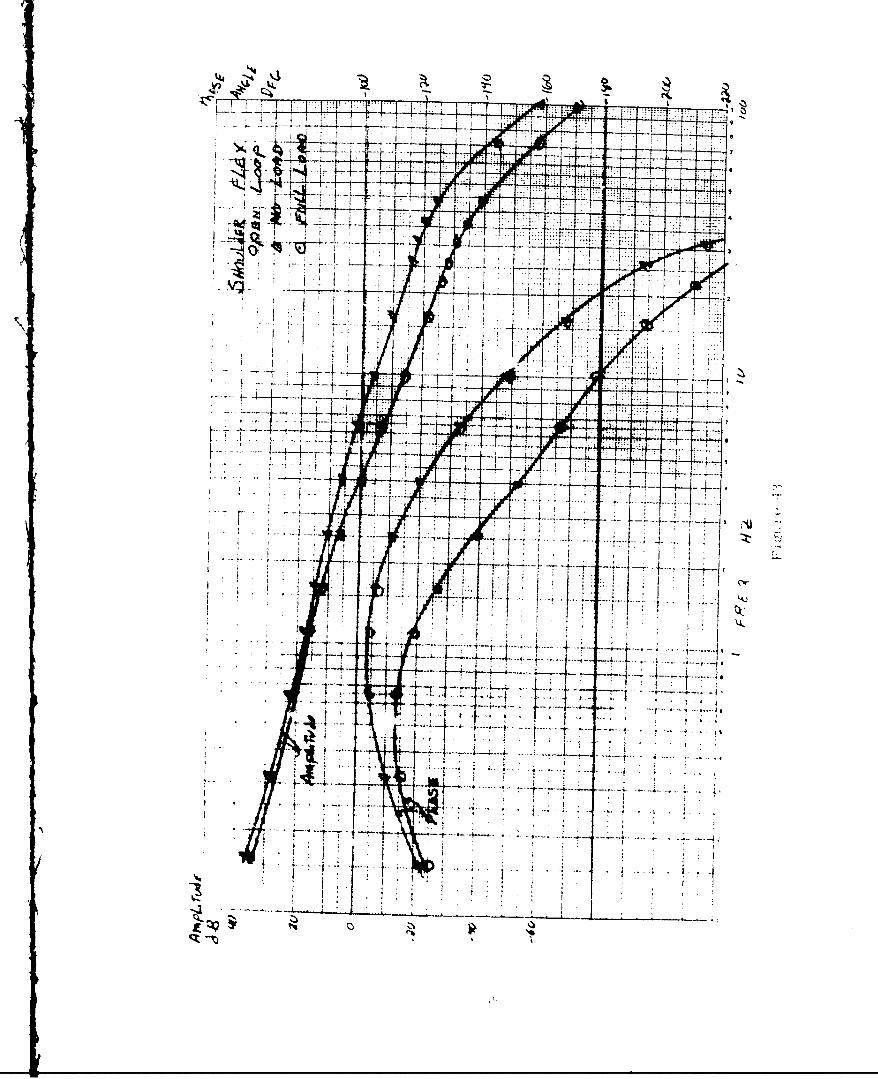
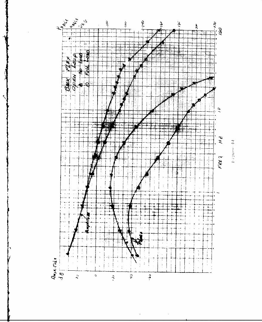
and compliance is given in Table II. Figures 39 through 44 are computed Bode
plots based on measured electrical gains.
SI
rr
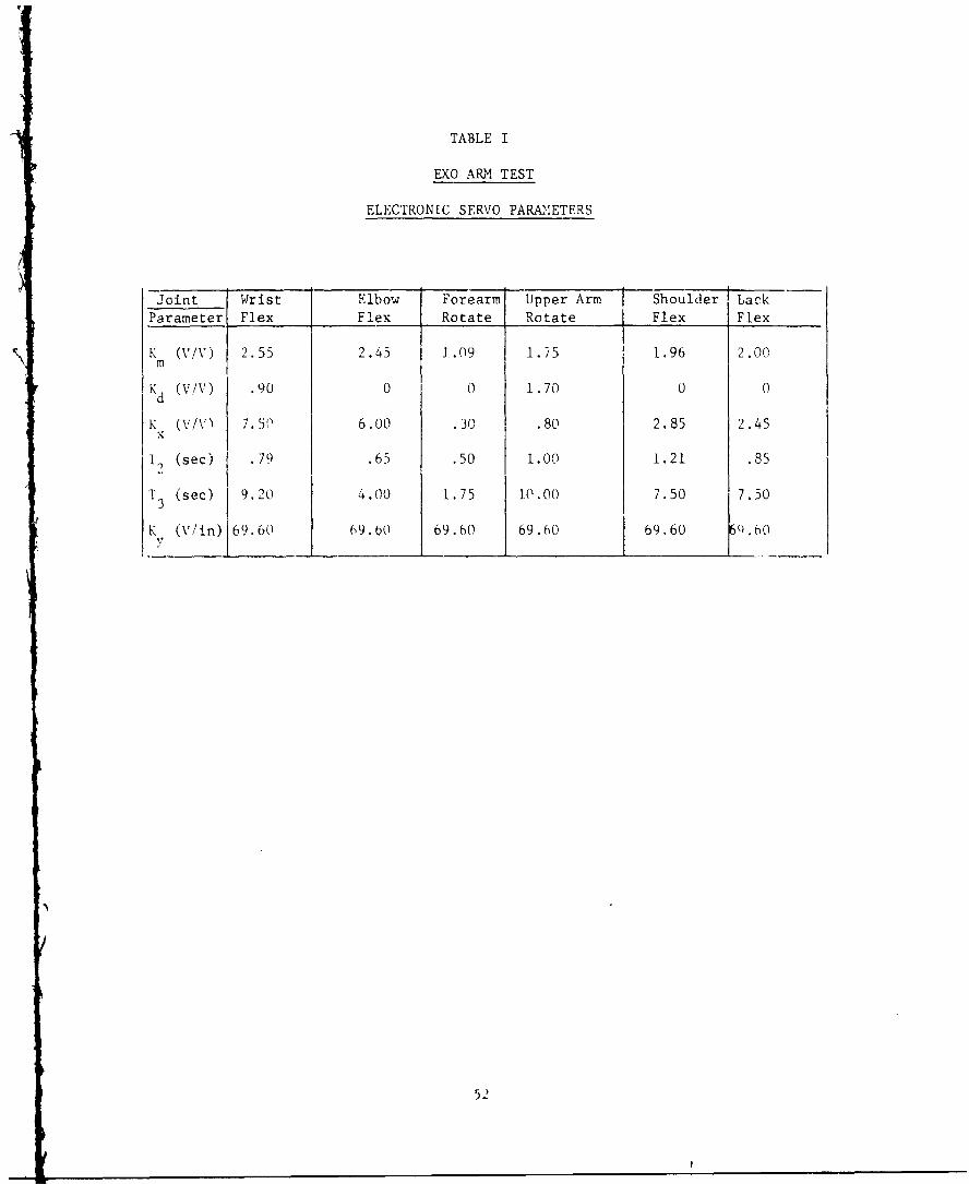
TABLE I
EXO ARM TEST
ELECTRONIC SERVO PARAMETERS
Joint Wrist Elbow Forearm Upper Arm Shoulder Lack
Parameter Flex Flex Rotate Rotate Flex Flex
K (%/V) 2.55 2.45 3.09 1.75 1.96 2.00N m
Kd (V/\) .90 0 0 1.70 0 0
K (V/V) 7.5f) 6.00 .30 .80 2.85 2.45
To (sec) .79 .65 .50 1.00 1.21 .85
T3 (sec) 9.20 4.00 1.75 i0.00 7.50 7.50
K (V/in) 69.60 69.60 69.60 69.60 I 69.60 60.60
52
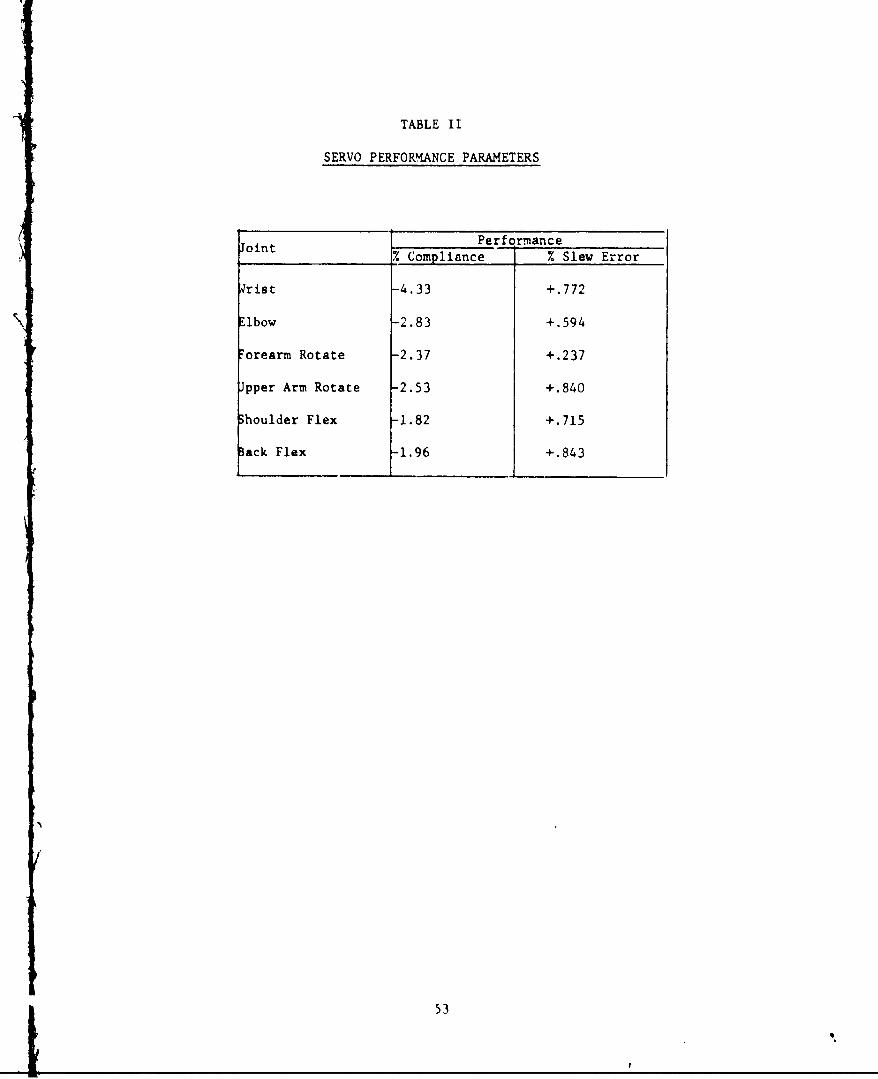
TABLE II
SERVO PERFORMANCE PARAMETERS
JointPerformanceoint% Compliance % Slew Error
Wrist -4.33 +.772
Elbow -2.83 +-.594
7orearm Rotate -2.37 +.237
Jpper Arm Rotate -2.53 +.840
3houlder Flex -1.82 +.715
Back Flex -.1.96 +.843
53
LL
rfit -
's.'I J'.', i?.IT
i.Li~. 41T1A:
Mt C)
Ir2r
r ..
TV I
7-4
-44-4
I04:
-I L
IL4LI
. .... ..
H~t~ -4%T
zip-
14 ~~-z7-
F77,TitiI
-
f r-
.-..
K~V I~+
~ t
DISTRIBUTION LIST
DPATZ1T, OF JEF7SE Copies
Assistant Secretary of Defense 1AMfN: Techical LibraryWzh~rngton, L. C. 20310
Office, Secretary of DefenseAivanced research Project AgencyPertagonWashington, D. C. 20310
Office, Secretary of Defense 1Office of Director, Defense Research and LEgineeringPentagonWashington, P. C. 20310
Defense Docunmntation Center 20Cameron Station, Building 55010 Duke StreetAlxandr ia, Virginia 22314
DirectorDefense Atcmic Support AwTencyashington, D. C. 2030.
Commaiding GeneralDefense Personnel Support Center2800 South 2LGL StreetPhiladelphia, Pen-,sylvania 19145
Ndvanced Research Projects Agency 1Department of DefenseWashington, D. C. 20310ArTM: Mr. A. Tedes:*-,, Rm. 3169, Pentagon
Dr. John J. Collins, Tec-mical Advisor for E >avioraland Social Sciences ResearchDeputy CNOPentagonWashingtcn, D. C. 20350
DLPARrMT, = OF '1l] ARMY
Clhief of Research and Developnint IDepartmnmn- of the ArnyWashington, D. C. 20310
ComrrndantConmnd and General Staff CollegeFort Leavenurth, Kansas 66027
DEPART'=N OF W'lE ARMY (Cont'd) Cpe
Departmrnt of the ArmyIAssistant Chief of Staff for Force DevelopmentWashington, D. C. 20310
Cormiaylant1Amy t-.'ar CcllegeArTN : ibraryCarlisle BarracksCarlisle, Pennsylbania 17013
Ccmmunding General 2TL. S. Continental Arm Cciwand
IN: Engineer SectionFort Monroe, Virginia 23351
Couatnding General 3 jU. S. PAy material CrrandDevelornent Directorate-G(SA=T: 1Mr. Alex HillWashinqrton, D. C. 20315
Corruncling OffiLcer1Franikford ArsenalATTN: LibraryPliladelph. ia, Pennsylvaria 1 37
,NrrmAm' zutions, CcIT-randPioauinny, Arse"mil
(i-A'Lib 'ardI
"t. 'Kuvi, Miassouri 63120
5.AiTi' (UQ * -.searchan'd IWxvelopm-nt kur Atorji esMTPN: L FIirr a
ix~l~4Arsenal, Ntiarmd 2101.0
S.AoyFKvoli cs Nasearch L r--vezVesTeXnt Aqexv--,XIN'N:I~ ThhaGl X~~ enter
i~rt~*k~r~ut7 *7 Jee T03
'.*xmv~tsnil, Alam'trKi351
DEPARTMENr OF THE ARMY (Cont'd) Copies
U. S. Army Natick LaboatoriesATMN: Technicel LibraryNatick, Ma ssachusetts 01762
Cemianding Officer 1U. S. Army Materials Research LaboratoriesWatertown ArsenalAT[N: LibraryWatertown, Massachusetts 02172
Commanding Officer 1U. S. Arny Ballistics Research LaboratoriesAberdeen Proving Ground, Maryland 21005
Commanding OfficerU. S. Arny Combined Arms GroupFort Leavenworth, Kansas 66027
Commandinq Officer 1U. S. Army Test and Evaluation ComandATqN : LibraryAberdeen, Mryland 21005
President 1U. S. Arxmy Infantry Board!>rt Benning, Georgia 31905
Ccvmun iing Officer 1
Fort Blcnning, CeAorqia 319C5
ileadcprtersU. S. Amy Aviation Schoolffi.ce of the Librarian
t ort Rucker, Alabanu 36362
Comtra iinc General '2S. Arm W.eapons CcurarK
I~ck Island ArsenrlIR ocJ Island, Illinois 61202
Durector of CBR Operations 1Dupxrtn)ent of the Arry'Washington, D. C. 20333
0ihef of Crnmuictions-Flectronics 1U)2pairtant of the Any,tishinqton, D. C. 20315
Director of Transportatiot, 1Department of the ArmyAThg: .. 0R-W%,.Ashington, D. C. 20 315
DEPARI!TET OF THElf ARMY (Cont ' d) ~e
DirectorU S. Army Engineer Waterways Experinent C;tatioriA=P: LibraryP. 0. Box 631 Halls Ferry RoadVicksburg, Mississippi 391831
Corrimanding Officer .U. S. Arny Pe search Support GroupFort Belvoir, Virginia 22060
Cormanding Off icerU SAC SSCFort Lee, Virginia 22060
Conmaring Off icerUSIZWFort Belvohi, Virginia 22060
Cbrmanding Of f cerProtective Struc ,ALes Feveloprent Center
= T: Libran'Fort Relvoir, Virginia 22060
Coniar0-ing of ftioeltSpocial Ccrnrittee for Counter insurgencyU. A..rmy Into11lcgerce Sdrbo1Fcrt Htolabirf, Moivland 2121.9
1'. S . Lrmy ILAg-istics Nmigervnt CantperFort Lee, \'irq.uvt'a 23801
I. S Ary John I,% Kenmnedy Center for Special WrfareFo~rt 11ragg, North l oln 28307
C ormku-KantU.. * Aryf ino,2r cx'NIT,,: LibraryFort W~lvoir, Virqinia 22000
Chic - f..% I'dison Off ice.A.;DL-S AerorLutical Systems Division1'Jr-iqht-Patterson Air FrCrr hje Nhio 45433
* C"IawderU. q. Amy %ijor Iter~s Supplli ' waagcTent
Charx~r~urq PrFyB'LLa 17201
PresidentIT. S. lum Trivsprtation Boiiwd7ort FPustis, Virqi' 4 a 2360A
DFITdMET OF THE APMY (Cont'd) Copie
Mr. Donald P. Kane 2 -nchanical Technology Dept. (ATIN: FB-HM)U. S. Arnmy mobility Equipment Researchand Development CenterFort Belvoir, Virginia 22060
DEPARrM1T OF THE AIR FORCE
Chief of StaffHeadquarters, United States Air ForceAAT!N: AFRST-C
AMACE-KCWashington, D. C. 20330
DirectorAir Force Office of Scientific ResearchATFN: Director of Chemical SciencesBuilding T-DWashington, D. C. 20330
DirectorAir Force Avionics laboratoryATTN: tAVRhight-Patterson Air Force 3ase, Ohio 45433
Cam nIde rAeronautical Systems Division
V'right-Patterson Air Force Rise, Ohio 45433
Aerospace Medical Division1. "viworal Science Laboratory.right-Patterson Air Force Base, Ohio 45433
A'I : Mr. W. N. Kama
Mr. hrold V. MarkAir Force lo-gistics ( 1)Wriqht-Patterson Air Force Base, Ohio 45433
i.:p,*uPAJ'T r OF T'a' NAVY
Chief of *ival Research 6(Cocle 455)
f* Ix~rtmamt of tbe NavyWaslungton, D. C. 20360
DEPARThET OF THE NAVY (Cont'd)
Commanding Officer 2
Office of Naval ResearchBranch Office, Box 39,FPO New York 09510ATTN: CDR N. Berry, USN, MSC
Chief, Bureau of nedicine and SurgeryPesearch DivisionDepartnent of the NavyWashington, D. C. 20390
Chief, Navy Ships Systems Comand1LibraryDepartment of the NavyWashington, D. C. 20360
Mi. Jack Wolin,,AAIR, Room IW92W. BuildiylgWashington, D. C. 20360
Departnunt of the NavyNAVA %IR (RA-15)h ashinqton, L. C. 20360
1 ic, diu~uters
'r.ne Co-T)ps., Comte :\XA\i ii~ P .ofAnn.exA' I xtqton, Virgizua
APTF C. Stastny
XW Rkv. Br., ."A\%1"!PkI: 1207", a\ ' Building"Asl IIIjtn, .C. 20 360
' . . 'ever 6AtTm trflt Support l juijpThnt Bramch"'\'AI .S<YSOi K (.',Yle 5344)P{xx 2330 Munitions BildingWaishinqton, D. C. 20360
Mr. Charles E. FDibergerResearch vn Development Division• A\'SLTSYSUf 1K), Code 0631.FWshinqton, D. C. 20360
Mr. M. r. EssoglouFAC-031%NAVTiEK-TWashington, D. C.
Mr. Fred AsfhbrookNaval Ordnance Test StationChina Lake, California
DEPARITNT OF THE 'NAVY (Cont'd) Copies
Mr. Flanagan Gray 1Naval Air Development CenterWarrinster, Pennsylvania 18974
Dr. R. J. LuidegardCode 430Office of Naval ResearchWashington, D. C. 20360
Dr. N. Perrone 1Code 439Office of Naval ResearchWaslunton, D. C. 20360
Colonel Johnl H. KingCode illOffice of Naval ResearchWashington, D. C. 20360
MAr. 11. A. O'NealCode 480Office of Naval ResearchV'ashington, D. C. 20360
Mtr. F. J. Rasmussen, DirectorSigineerlng Support DivisionNA)R.DSYSC(rn 110Code 0M 934Washington, D. C. 20360
.Mr. T. SatterthQute\xval Ship Systems Ca-wund
lkxxi 3645 >in Nay, BukildingNashington, ). C. 20360
MIr. L. C. CanpbellNaval Supply Systems CamvlmaI\istngton, D. C. 20360
Captain S. P. Cantz 1Asst. DCZ (D)IRxn 2016 Maili Navy BuildingWashington, D. C. 20360
Mr. L. R. Caringe 1U. '*. Naval mmiunit.ion DepotNaval Weapons Landling laboratory1-arle Colts Neck, New Jersey
Mtr. C. J. Heinrich,. S. Naval SupplyResearch and Development FacilityEiyonne, New Jersey
DLINZ710, OF TIE: NAVY (Cont'(') ~e
Nxial Research Laboratory 6AITIj L1ibrarywashin(rton, D. C. 20390
TVeclmical Director1N aval Civil Engineering LI1oratoryPort H uenemre, California
Lt, Col. Dock IA. Pegues, Head1Comba.t Service BranchConbat Service Suppo~rt Divisiontairine Corps. Landiing Force Develop-nt CenterOuantico, Virqinia 22134
Serlior Standardization Representative1US. Amy starxardization Group
Ottawa, aniada
Lsonior St artii zation !representative1LT. S. Army Standardization~ GroupL-ondon, Lg ~
r.Stxiley LAutsch, Advanced Research1and Th1chrxnlogy, ,,ASA 5q. 600 Independience Ave., S.W.',da~hinqtofl, D. C. 20546
.'Aorcspce >k iial Diiio
Pcluhvorial Science hLboratoryriqt-Pattcr5son AMP, oihio 45433
ALi%%: Dr. J. .'.. Chiristensen
P eter Creuene. ,* rrittoor n1fora't tof Sciences
'2 )reX01
Proessor 'I-mvin MinskyFllocur caI tigineeriiq Depai :Tint"issachusetts Institute of Techmolojy
~'ar~r i q,t1Ss1Chujfet tS 02139
Victor C. AndersonCnivcsftvof Califlornia, Su,, Die~j
MIarine Physical I.ib of thec ,ripps iflstitution of oo~mawgraphy
San Dioo Cil.fornia 92152
',r. J. W. tLIwkins1-bixt Research1250 Plrostnect St. k 5aite C-23)la Jolla, California- 92037
CYlrIRS (Cont'd) Copies
ICDR Thomas J. GallagherAviation Operational Psychology BranchBureau of Medicine and SurgeryBldg. 3, Room 3108Washington, D. C. 20390
Dr. Ileber MooreOtfice of Naval M1aterialCode 3253Washington, D. C. 20360
Aerospace Crew Equipnent LaboratoryNaval Air Engineering CenterPhiladelphia, Penns-,vania 19112
Mr. Robert A. Jonescmean Engineering
%AVSEC 6162, Departnnt of the NavyRoom 4646 'Main -'avy BuildingWashington, D. C. 20360
Head, uiua; 1 Factors Divisiont. S. Navy Electronics l[.aoratory,u Diego, California 92152
[). ,J ius J. Regan, BeadPsvcholoqical Ilai)ratory (Code 55)
[. Naval ra-ining Device Centerl<rt Wiaslunqton, L. 1., N. Y. 11050
t\Aruaier, li. 5. Naval "issile CenterAt'P..: (bmnder H!. Ihy, USN, }C!,onnt 'tJ , Californii 93041
ial Onr-irumice I LcratoryXI'V, : Librutryhite k< k
Silvor .prag, MLArylum 20907
Dr. A. 1 erunett Wilsl)n, Jr.I~tA~AV. Direc:tor, (JTMJ
-itional Acadery of Sciences2101 Constitution Ave., N. W.Wastunqt, 1). C. 20418
D Iugerx- F. .irphyL1ef Reserdh ai. Development DivisionlProsth etic & Sensory Aids Service - Veterans .,.trin.'22 Seventh- AvenueNew York, New York 10001
fii{xo ical Electronics LaLnratoryDenver Sesearch Institute
Uiuversitv of DenverDanve_,,( 1orado 80201
(YfP1S (Cont t d) Copies
Dr. James Reswick, DirectorFngineering Design CenterCase Institute of Technologyuriversity CircleCleveland, Ohio 44102
Dr. William BradleyInstitute for Defense Analysis400 - Army-Navy DriveArlington, Virginia
Dr. Fred Leonard, Scientific DirectorAmy Medical Bianechanical Research LaboratoryWalter Reed Army Medical CenterForest Glen SectionWashington, D. C. 20012
Transportation Research DepartmentCornell Aeronautical Laboratory, Inc.Buffalo, New York 14221
Mr. G. Forida-Bonarda.Space Scienoes LaboratoriesLitton Syster s, Inc.
36 North FvJ-k)ill RpoJklOverly h ills, California
Dr. Patrick J. Doyle, Deputy Camuissioer1Vocat ia-I Reihbil i tation brinistrationHI Building Nrthi
Wdkus;unkitu: , D. C. 201201
pr'o r 'pams Sher ian:)epcu-trm-it of Mechanical 1gaciveering
-isachukctts -istitute of Teccllogy
Carir idgje, .assachuwe t ts 02139
.- Lunt Kizirr.isdroumn Support Division?,ro Pr(.,vuls iofn aidrator-yWraht-Patterson Air Force Base, Ohio 45433
:]. P. J. l s-i
vseaurch' Physio lx.jist',kdicai Field Research LalxratoryCinT lAieue, .North\ Carolina
Dr. Ve r)n L. Nickel, Medcal DirectorRanchos LAs A'-v,. fbspital601 Fnst llaeral }ightly
Downey, Cali forrua 90242
CTHEPS tCont'd) Copies
Mr. Edwin G. JohnsenChief, Equapnent and Facilities BranchSpace Nuclear Propulsion OfficeU. $. Atomic Energy ConmrissionWashington, D. C. 20545
Mr. Howard Kusru.t7, Assistant DirectorNational Center for Urban and Industrial HealthU. S. Public Health Service222 E. Central ParkwayCincinnati, Ohio 45202
Dr. Karl U. ScuthDepartrrent of PsychologyUnlversity of WisconsinMadison, Wisconsin 53706
Mr. Lee Harrison, IIICorr1uter Imnage Corporation2162 South Jason StreetLnver, Colorado 80223
r *vl:m Pcsch, harkin Factors SectionGeneral Dynamics, Electric Boat DivisionE;astern Point Rozidroton, Cornectivat 06340
Dr. 'lton S. FKAtzKatz & Associates7411 Bevwerly RoatdHethtlsda, Marylan-l 20014
tr, iouqlas Y. Cor!-x;(,ii 1 , Huro~n Factors FranchBureau of Research and l~iireer ingU. l. Post Office lltirtment
~.ashinton, E. C. 22:
Dr. 1). T. McRierv~teyt c'chrc y Inc.
EnTr , (liii feorr Q0250
;.rpt. :'!In . a.srmlssen, VrN, !t&.
rl_.. ! Development (.W1T;,-U 3L2.1)
it-, i017, t ti Na\ ,y tuilinqVIish.vhttong , P. C. 20360
Or. Moirton 13crtin
:'jxirurlent uf tlyV' Na-y4tic-e of Naval -esearc, !ranch Office
219 South Dearboin StreetCucw, 2limis ..604
C F~IRS (Cont'cd) copies
Departnrnt of the Navy[X~m Development (IZIT-03lB)izm-rn 1010, ma~in Navy Buildingt-ashingtoni, D. C. 20360
Dii ectorate of tilitary TecnixoryInstitute of iarnJ CombatC'. S. \xrry Combat [Developmrent ConrmarkdFort !elvoir, Virginia 22060AN: Mr. Alexander Levin
Mr:. t\ sley I. GrieveAir Force Systevs Confloancisscientific & Techn-ical Liaison Officetunitions B3ldg., Rom. 3543
Was-ington, D. C. 20360
Ccm-rxi ing OfficerNaval Mdr EYngL"neering CenterPhiladelphia, Pennsylvania:%TN: SE-LK
Mr. Patrick W. WNanIN-rsonnel Suhbsystem 1.7bratories11he lc i nc CarpclnyM ilitary Airplane- ,\.stemt Division
-koattlo, Washinqton 98124
Unclassified. I ,,,y Ch.f,c,¢tion
DOCUMENT CONTROL DATA . R & D(Security clesillcation of title, body of abettect and i'idexind ennotatio. must be entered when the o,,rall re" tt I classilled)
ON'JH *NA TING ACTIVITY (Corporate autho") '1.. REPORT SECURITY CLASSIFICATION
Specialty Materials .a:ndling Products Operation, UnclassifiedResearch and Development, General Electric Company 2b. GRoup
Schenectady, New York 123053 REPORT TITLE
HARDIMAN I Prototype Project -- HARDIMAN I Arm Test
4 rr "Ce's- VE NOTES (rype otdreptt and Inctuelve date.)
Summary of Program progress through December 31, 1969S. AU TMOR.$) (First name, middle Initial, lst name)
P.F. Croshaw
6 P. pI O*
T aT Ve7a. TOTAL NO. OF PAGIS ?b. NO, Or Rps
December 31, 1969 59li. CO(N ikAC T OR GRANT NO Cam ORIGINATOR'S REPORT NU#uERIKJSI
Contract N00014-66-C0051h 'OE4 S-70-1019
Contract Authorization Ident.No. NR 196-049 (HARDIMAN) ,6. OTNR NEPORT NOS) (Any othernm, tre hat y be a..id
dProject No. LM624101050702I: 01rv.'- T,0 S TAT ibdg T
This document has been approved for public release and sale; its distributionis unlimited.
"',p... |,o ,12 SPONSORNG LITANY ACTIVIY
* Office of Naval ResearchNaval Air S ystems Commandrmy Mobili y Equipment
_esearch and Deve I ment Center
Thii. is a discussion of the test and evaluation of the HARDIMAN I leftea,.- assembly.
The HARDIMAN I prototype is a powered txoskeletal harness which will amplify man'sstrength and endurance while retaining his versatility and dexterity.
The objective of the arm test was to investigate human factors and servo per-
formance while lifting a load.
N
DD 't..1473 Unclassified!.ecUvlI% C .11%'.al,'R
UnclassifiedSecurit% Class.fiation
14 LINK A LINK 8 LINK CKEY WOROS ..
ReLC Wr ROLE WT ROLE I V T
HARDIIAN
Exoskeleton
Manipulator
Bilateral Servos
Joints-in-Series
I
I I
t1i'
! [tn. lassif ied