Embed Size (px)
Citation preview
5K1500 OEM Specification
Hard Disk Drive Specification
HGST Travelstar 5K1500 2.5 inch SATA hard disk drive
Models: HTS541515A9E630
Revision 1.0 30 May 2013
1
5K1500 OEM Specification
The 1st Edition (Revision 0.1 Preliminary) (25 April 2013)
The 2nd Edition (Revision 1.0 ) (30 May 2013)
The following paragraph does not apply to the United Kingdom or any country where such provisions are inconsistent with local law: HGST, A WESTERN DIGITAL COMPANY PROVIDES THIS PUBLICATION "AS IS" WITHOUT WARRANTY OF ANY KIND, EITHER EXPRESS OR IMPLIED, INCLUDING, BUT NOT LIMITED TO, THE IMPLIED WARRANTIES OF MERCHANTABILITY OR FITNESS FOR A PARTICULAR PURPOSE. Some states do not allow disclaimer or express or implied warranties in certain transactions, therefore, this statement may not apply to you.
This publication could include technical inaccuracies or typographical errors. Changes are periodically made to the information herein; these changes will be incorporated in new editions of the publication. HGST may make improvements or changes in any products or programs described in this publication at any time.
It is possible that this publication may contain reference to, or information about, HGST products (machines and programs), programming, or services that are not announced in your country. Such references or information must not be construed to mean that HGST intends to announce such HGST products, programming, or services in your country.
Technical information about this product is available by contacting your local HGST representative or on the Internet at http://www.hgst.com
HGST may have patents or pending patent applications covering subject matter in this document. The furnishing of this document does not give you any license to these patents.
© Copyright HGST, a Western Digital company
HGST, a Western Digital company 3403 Yerba Buena Road San Jose, CA 95135 Produced in the United States 05/13 All rights reserved. Travelstar™ is a trademark of HGST, a Western Digital company. HGST trademarks are authorized for use in countries and jurisdictions in which HGST has the right to use, market and advertise the brands. Other product names are trademarks or registered trademarks of their respective owners. One GB is equal to one billion bytes and one TB equals 1,000 GB (one trillion bytes) when referring to hard drive capacity. Accessible capacity will vary from the stated capacity due to formatting and partitioning of the hard drive, the computer’s operating system, and other factors. References in this publication to HGST products, programs or services do not imply that HGST intends to make these available in all countries in which HGST operates. Product information is provided for information purposes only and does not constitute a warranty. Information is true as of the date of publication and is subject to change. Actual results may vary. This publication is for general guidance only. Photographs may show design models. 30 May 2013
2
5K1500 OEM Specification
Table of contents 1 GENERAL ..........................................................................................................................................................9
1.1 Introduction .........................................................................................................................................9 1.2 Abbreviations.......................................................................................................................................9 1.3 References ..........................................................................................................................................11 1.4 General caution .................................................................................................................................11 1.5 Drive handling precautions ..............................................................................................................11
2 OUTLINE OF THE DRIVE...................................................................................................................................12
PART 1 FUNCTION SPECIFICATION ..........................................................................................................13
3 FIXED DISK SUBSYSTEM DESCRIPTION ............................................................................................................14 3.1 Control Electronics ............................................................................................................................14 3.2 Head disk assembly data ..................................................................................................................14
4 FIXED DISK CHARACTERISTICS........................................................................................................................15 4.1 Formatted capacity by model number..............................................................................................15 4.2 Data sheet ..........................................................................................................................................15 4.3 Cylinder allocation ............................................................................................................................16 4.4 Performance characteristics .............................................................................................................17
5 DATA INTEGRITY .............................................................................................................................................21 5.1 Data loss on power off .......................................................................................................................21 5.2 Write Cache .......................................................................................................................................21 5.3 Equipment status ..............................................................................................................................21 5.4 WRITE safety.....................................................................................................................................21 5.5 Data buffer test..................................................................................................................................22 5.6 Error recovery....................................................................................................................................22 5.7 Automatic reallocation ......................................................................................................................22
6 SPECIFICATION ...............................................................................................................................................23 6.1 Environment ......................................................................................................................................23 6.2 DC power requirements ....................................................................................................................25 6.3 Reliability...........................................................................................................................................26 6.4 Mechanical specifications..................................................................................................................29 6.5 Vibration and shock...........................................................................................................................31 6.6 Acoustics.............................................................................................................................................33 6.7 Identification labels...........................................................................................................................34 6.8 Electromagnetic compatibility..........................................................................................................34 6.9 Safety..................................................................................................................................................35 6.10 Packaging...........................................................................................................................................35 6.11 Substance restriction requirements .................................................................................................35
7 ELECTRICAL INTERFACE SPECIFICATIONS ......................................................................................................36 7.1 Cabling ...............................................................................................................................................36 7.2 Interface connector ............................................................................................................................36 7.3 Signal definitions...............................................................................................................................37
PART 2 INTERFACE SPECIFICATION ........................................................................................................39
8 GENERAL ........................................................................................................................................................40 8.1 Introduction .......................................................................................................................................40 8.2 Terminology .......................................................................................................................................40
9 DEVIATIONS FROM STANDARD ........................................................................................................................40 10 PHYSICAL INTERFACE ...................................................................................................................................40 11 REGISTERS ....................................................................................................................................................41
11.1 Register naming convention .............................................................................................................41 11.2 Command register .............................................................................................................................42 11.3 Device Control Register.....................................................................................................................42 11.4 Device Register ..................................................................................................................................42 11.5 Error Register ....................................................................................................................................43 11.6 Features Register ..............................................................................................................................43 11.7 LBA High Register ............................................................................................................................43 11.8 LBA Low Register..............................................................................................................................43 11.9 LBA Mid Register ..............................................................................................................................43 11.10 Sector Count Register....................................................................................................................44
3
5K1500 OEM Specification
11.11 Status Register...............................................................................................................................44 12 GENERAL OPERATION DESCRIPTIONS ..........................................................................................................45
12.1 Reset Response ..................................................................................................................................45 12.2 Diagnostic and Reset considerations................................................................................................46 12.3 Power-off considerations ...................................................................................................................47 12.4 Sector Addressing Mode....................................................................................................................48 12.5 Power Management Feature ............................................................................................................49 12.6 Advanced Power Management (Adaptive Battery Life Extender 3) Feature................................51 12.7 Interface Power Management Mode (Slumber and Partial)...........................................................52 12.8 S.M.A.R.T. Function..........................................................................................................................53 12.9 Security Mode Feature Set ...............................................................................................................54 12.10 Protected Area Function................................................................................................................60 12.11 Write Cache Function....................................................................................................................63 12.12 Reassign Function..........................................................................................................................63 12.13 48-bit Address Feature Set............................................................................................................64 12.14 Software Setting Preservation Feature Set .................................................................................65 12.15 Native Command Queuing............................................................................................................66 12.16 SMART Command Transport (SCT).............................................................................................66 12.17 Power-Up In Standby (PUIS) feature set.....................................................................................67 12.18 Early Drive Ready (EDR) function ...............................................................................................68
13 COMMAND PROTOCOL...................................................................................................................................71 13.1 Data In Commands ...........................................................................................................................71 13.2 Data Out Commands.........................................................................................................................71 13.3 Non-Data Commands ........................................................................................................................72 13.4 DMA Data Transfer Commands.......................................................................................................73 13.5 First-parity DMA Commands...........................................................................................................73
14 COMMAND DESCRIPTIONS ............................................................................................................................74 14.1 Check Power Mode (E5h/98h)...........................................................................................................78 14.2 Device Configuration Overlay (B1h) ................................................................................................79 14.3 Download Microcode (92h) ................................................................................................................83 14.4 Execute Device Diagnostic (90h) ......................................................................................................85 14.5 Flush Cache (E7h) .............................................................................................................................86 14.6 Flush Cache Ext (Eah) ......................................................................................................................87 14.7 Format Track (50h: Vendor Specific) ...............................................................................................88 14.8 Format Unit (F7h: Vendor Specific) .................................................................................................89 14.9 Identify Device (Ech) .........................................................................................................................90 14.10 Idle (E3h/97h)...............................................................................................................................102 14.11 Idle Immediate (E1h/95h) ...........................................................................................................103 14.12 Initialize Device Parameters (91h) .............................................................................................104 14.13 Read Buffer (E4h) ........................................................................................................................105 14.14 Read DMA(C8h/C9h) ...................................................................................................................106 14.15 Read DMA Ext (25h)....................................................................................................................107 14.16 Read FPDMA Queued (60h)........................................................................................................108 14.17 Read Log Ext(2fh) ........................................................................................................................109 14.18 Read Log DMA Ext(47h) .............................................................................................................117 14.19 Read Multiple (C4h).....................................................................................................................118 14.20 Read Multiple Ext (29h) ..............................................................................................................119 14.21 Read Native Max Address (F8h).................................................................................................120 14.22 Read Native Max Address Ext (27h) ..........................................................................................121 14.23 Read Sector(s) (20h/21h)..............................................................................................................122 14.24 Read Sector(s) Ext (24h)..............................................................................................................123 14.25 Read Verify Sector(s) (40h/41h) ..................................................................................................124 14.26 Read Verify Sector(s) Ext (42h)...................................................................................................125 14.27 Recalibrate (1xh)..........................................................................................................................126 14.28 Security Disable Password (F6h)................................................................................................127 14.29 Security Erase Prepare (F3h) .....................................................................................................128 14.30 Security Erase Unit (F4h) ...........................................................................................................129 14.31 Security Freeze Lock (F5h) .........................................................................................................130 14.32 Security Set Password (F1h) .......................................................................................................131 14.33 Security Unlock (F2h)..................................................................................................................133 14.34 Seek (7xh) .....................................................................................................................................134
4
5K1500 OEM Specification
14.35 Sense Condition (F0h : vendor specific)......................................................................................135 14.36 Set Features (Efh)........................................................................................................................136 14.37 Set Max Address (F9h) ................................................................................................................138 14.38 Set Max Address Ext (37h)..........................................................................................................140 14.39 Set Multiple (C6h)........................................................................................................................142 14.40 Sleep (E6h/99h) ............................................................................................................................143 14.41 S.M.A.R.T Function Set (B0h) ....................................................................................................144 14.42 Standby (E2h/96h) .......................................................................................................................159 14.43 Standby Immediate (E0h/94h) ....................................................................................................160 14.44 Write Buffer (E8h) .......................................................................................................................161 14.45 Write DMA (Cah/Cbh) .................................................................................................................162 14.46 Write DMA Ext (35h)...................................................................................................................163 14.47 Write DMA FUA Ext (3dh)..........................................................................................................164 14.48 Write FPDMA Queued (61h).......................................................................................................165 14.49 Write Log Ext(3fh) .......................................................................................................................166 14.50 Write Log DMA Ext (57h) ...........................................................................................................167 14.51 Write Multiple (C5h)....................................................................................................................168 14.52 Write Multiple Ext (39h) .............................................................................................................169 14.53 Write Multiple FUA Ext (Ceh)....................................................................................................170 14.54 Write Sector(s) (30h/31h).............................................................................................................171 14.55 Write Sector(s) Ext (34h).............................................................................................................172 14.56 Write Uncorrectable Ext (45h)....................................................................................................173
15 TIMINGS ......................................................................................................................................................175
5
5K1500 OEM Specification
List of Figures Figure 1 Limits of temperature and humidity 23 Figure 2 Mounting hole locations 29 Figure 3 Interface connector pin assignments 36 Figure 4 Parameter descriptions 38 Figure 5 Initial Setting 55 Figure 6 Usual Operation 56 Figure 7 Password Lost 57 Figure 8 Set Max security mode transition 62 Figure 9 Selective self-test test span example 146
List of Tables Table 1 Formatted capacity by model number. 15 Table 2 Data sheet 15 Table 3 Cylinder allocation 16 Table 4 Performance characteristics 17 Table 5 Mechanical positioning performance 18 Table 6 Full stroke seek time 18 Table 7 Single track seek time 18 Table 8 Latency time 18 Table 9 Drive ready time 19 Table 10 Operating mode 20 Table 11 Drive ready time 20 Table 12 Environmental condition 23 Table 13 Magnetic flux density limits 24 Table 14 DC Power requirements 25 Table 15 Power consumption efficiency 25 Table 16 Physical dimensions and weight 29 Table 17 Random vibration PSD profile breakpoints (operating) 31 Table 18 Swept sine vibration 31 Table 19 Random Vibration PSD Profile Breakpoints (non-operating) 32 Table 20 Operating shock 32 Table 21 Non-operating shock 32 Table 22 Weighted sound power 33 Table 23 Interface connector pins and I/O signals 37 Table 24 Register naming convention and correspondence 41 Table 25 Device Control Register 42 Table 26 Device Register 42 Table 27 Error Register 43 Table 28 Status Register 44 Table 29 Reset Response Table 45 Table 30 Default Register Values 46 Table 31 Diagnostic Codes 46 Table 32 Reset error register values 46 Table 33 Device’s behavior by ATA commands 47 Table 34 Power conditions 50 Table 35 Command table for device lock operation 58 Table 36 Command table for device lock operation - continued 59 Table 37 Set Max Set Password data content 61 Table 38 Preserved Software Setting 65 Table 39 SCT Action Code Supported 66 Table 40 PM4: PUIS command behavior 67 Table 41 Command Type for Early Drive Ready 69 Table 42 Command Type for Early Drive Ready –Continue- 70 Table 43 Command set 74 Table 44 Command Set - continued 75 Table 45 Command Set (Subcommand) 76 Table 46 Check Power Mode Command (E5h/98h) 78 Table 47 Device Configuration Overlay Command (B1h) 79 Table 48 Device Configuration Overlay Features register values 79
6

5K1500 OEM Specification
Table 49 Device Configuration Overlay Data structure 81 Table 50 DCO error information definition 82 Table 51 Download Command (92h) 83 Table 52 Execute Device Diagnostic Command (90h) 85 Table 53 Flush Cache Command (E7h) 86 Table 54 Flush Cache EXT Command (Eah) 87 Table 55 Format Track Command (50h) 88 Table 56 Format Unit Command (F7h) 89 Table 57 Identify Device Command (Ech) 90 Table 58 Identify device information 91 Table 59 Identify device information --- Continued --- 92 Table 60 Identify device information --- Continued --- 93 Table 61 Identify device information --- Continued --- 94 Table 62 Identify device information --- Continued --- 95 Table 63 Identify device information --- Continued --- 96 Table 64 Identify device information --- Continued --- 97 Table 65 Identify device information --- Continued --- 98 Table 66 Identify device information --- Continued --- 100 Table 67 Number of cylinders/heads/sectors by models for HTS5415XXA9X6XX 101 Table 68 Idle Command (E3h/97h) 102 Table 69 Idle Immediate Command (E1h/95h) 103 Table 70 Initialize Device Parameters Command (91h) 104 Table 71 Read Buffer Command (E4h) 105 Table 72 Read DMA Command (C8h/C9h) 106 Table 73 Read DMA Ext Command (25h) 107 Table 74 Read FPDMA Queued Command (60h) 108 Table 75 Read Log Ext Command (2fh) 109 Table 76 Log address definition 109 Table 77 General purpose Log Directory 110 Table 78 Extended comprehensive SMART error Log 110 Table 79 Extended Error log data structure 111 Table 80 Command data structure 111 Table 81 Error data structure 112 Table 82 Extended Self-test log data structure 113 Table 83 Extended Self-test log descriptor entry 113 Table 84 Command Error information 114 Table 85 Phy Event Counter Identifier 115 Table 86 Phy Event Counter information 116 Table 87 Read Log Ext DMA Command (47h) 117 Table 88 Read Multiple Command (C4h) 118 Table 89 Read Multiple Ext Command (29h) 119 Table 90 Read Native Max Address Command (F8h) 120 Table 91 Read Native Max Address Ext Command (29h) 121 Table 92 Read Sector(s) Command (20h/21h) 122 Table 93 Read Sector(s) Ext Command (24h) 123 Table 94 Read Verify Sector(s) Command (40h/41h) 124 Table 95 Read Verify Sector(s) Ext Command (42h) 125 Table 96 Recalibrate Command (1xh) 126 Table 97 Security Disable Password Command (F6h) 127 Table 98 Password Information for Security Disable Password command 127 Table 99 Security Erase Prepare Command (F3h) 128 Table 100 Security Erase Unit Command (F4h) 129 Table 101 Erase Unit Information 129 Table 102 Security Freeze Lock Command (F5h) 130 Table 103 Security Set Password Command (F1h) 131 Table 104 Security Set Password Information 131 Table 105 Security Unlock Command (F2h) 133 Table 106 Security Unlock Information 133 Table 107 Seek Command (7xh) 134 Table 108 Sense Condition Command (F0h) 135 Table 109 Set Features Command (Efh) 136 Table 110 Set Max Address Command (F9h) 138 Table 111 Set Max Address Ext Command (37h) 140 Table 112 Set Multiple Command (C6h) 142
7
5K1500 OEM Specification
Table 113 Sleep Command (E6h/99h) 143 Table 114 S.M.A.R.T. Function Set Command (B0h) 144 Table 115 Log sector addresses 147 Table 116 Device Attribute Data Structure 149 Table 117 Individual Attribute Data Structure 150 Table 118 Status Flag Definitions 151 Table 119 Device Attribute Thresholds Data Structure 154 Table 120 Individual Threshold Data Structure 154 Table 121 SMART Log Directory 155 Table 122 S.M.A.R.T. error log sector 155 Table 123 Error log data structure 156 Table 124 Command data structure 156 Table 125 Error data structure 156 Table 126 Self-test log data structure 157 Table 127 Selective self-test log data structure 158 Table 128 S.M.A.R.T. Error Codes 158 Table 129 Standby Command (E2h/96h) 159 Table 130 Standby Immediate Command (E0h/94h) 160 Table 131 Write Buffer Command (E8h) 161 Table 132 Write DMA Command (Cah/Cbh) 162 Table 133 Write DMA Ext Command (35h) 163 Table 134 Write DMA FUA Ext Command (3dh) 164 Table 135 Write FPDMA Queued Command (61h) 165 Table 136 Write Log Ext Command(3fh) 166 Table 137 Write Log DMA Ext Command (57h) 167 Table 138 Write Multiple Command (C5h) 168 Table 139 Write Multiple Ext Command (39h) 169 Table 140 Write Multiple FUA Ext Command (Ceh) 170 Table 141 Write Sector(s) Command (30h/31h) 171 Table 142 Write Sector(s) Ext Command (34h) 172 Table 143 Write Uncorrectable Ext Command (45h) 173 Table 144 Timeout Values 175
8
5K1500 OEM Specification
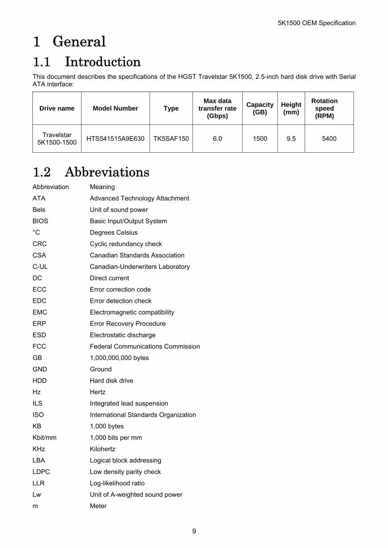
1 General 1.1 Introduction This document describes the specifications of the HGST Travelstar 5K1500, 2.5-inch hard disk drive with Serial ATA interface:
Drive name Model Number Type Max data
transfer rate(Gbps)
Capacity (GB)
Height (mm)
Rotation speed (RPM)
Travelstar 5K1500-1500
HTS541515A9E630 TK5SAF150 6.0 1500 9.5 5400
1.2 Abbreviations Abbreviation Meaning
ATA Advanced Technology Attachment
Bels Unit of sound power
BIOS Basic Input/Output System
°C Degrees Celsius
CRC Cyclic redundancy check
CSA Canadian Standards Association
C-UL Canadian-Underwriters Laboratory
DC Direct current
ECC Error correction code
EDC Error detection check
EMC Electromagnetic compatibility
ERP Error Recovery Procedure
ESD Electrostatic discharge
FCC Federal Communications Commission
GB 1,000,000,000 bytes
GND Ground
HDD Hard disk drive
Hz Hertz
ILS Integrated lead suspension
ISO International Standards Organization
KB 1,000 bytes
Kbit/mm 1,000 bits per mm
KHz Kilohertz
LBA Logical block addressing
LDPC Low density parity check
LLR Log-likelihood ratio
Lw Unit of A-weighted sound power
m Meter
9
5K1500 OEM Specification
max. or Max. Maximum
MB 1,000,000 bytes
Mbps 1,000,000 Bit per second
MHz Megahertz
mm Millimeter
ms Millisecond
Nm Newton meter
No. or # Number
oct/min Oscillations per minute
PSD Power spectral density
RFI Radio frequency interference
RH Relative humidity
% RH Percent relative humidity
RMS Root mean square
RPM Revolutions per minute
RS Read Solomon
R/W Read/Write
sec Second
Sect/Trk Sectors per track
SELV Secondary low voltage
S.M.A.R.T Self-monitoring, analysis, and reporting technology
TB 1,000,000,000,000 bytes
Trk. Track
UL Underwriters Laboratory
V Volt
W Watt
10
5K1500 OEM Specification
1.3 References Serial ATA International Organization: Serial ATA Revision 3.0
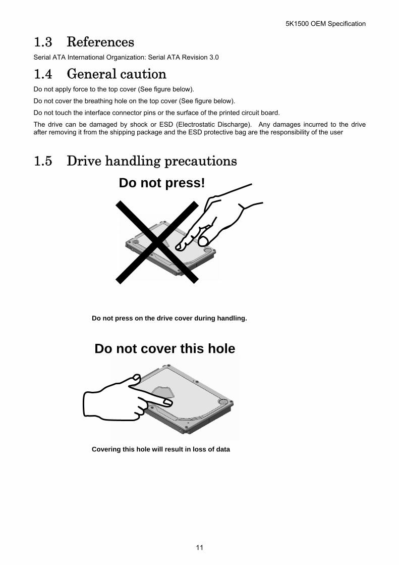
1.4 General caution Do not apply force to the top cover (See figure below).
Do not cover the breathing hole on the top cover (See figure below).
Do not touch the interface connector pins or the surface of the printed circuit board.
The drive can be damaged by shock or ESD (Electrostatic Discharge). Any damages incurred to the drive after removing it from the shipping package and the ESD protective bag are the responsibility of the user
1.5 Drive handling precautions
Do not press!
Do not press on the drive cover during handling.
Do not cover this hole
Covering this hole will result in loss of data
11
5K1500 OEM Specification
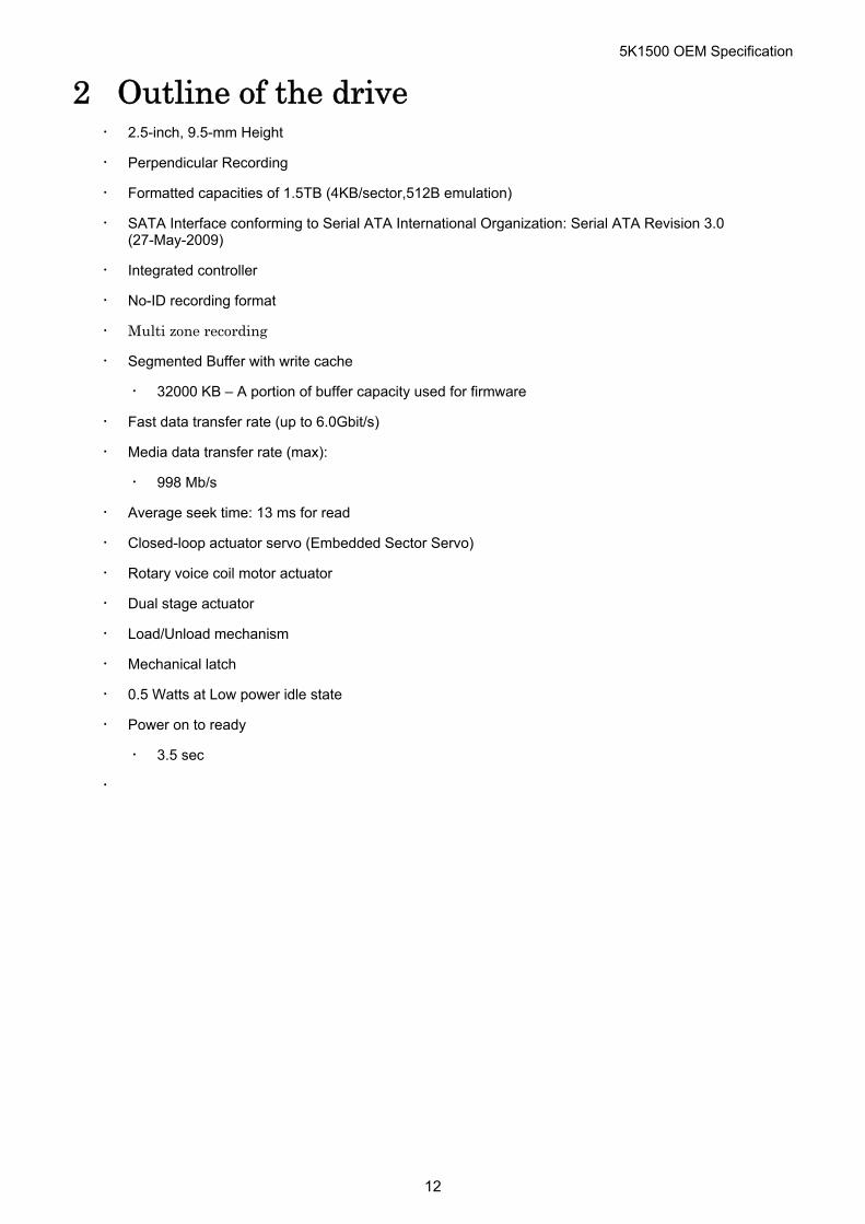
2 Outline of the drive ・ 2.5-inch, 9.5-mm Height
・ Perpendicular Recording
・ Formatted capacities of 1.5TB (4KB/sector,512B emulation)
・ SATA Interface conforming to Serial ATA International Organization: Serial ATA Revision 3.0 (27-May-2009)
・ Integrated controller
・ No-ID recording format
・ Multi zone recording
・ Segmented Buffer with write cache
・ 32000 KB – A portion of buffer capacity used for firmware
・ Fast data transfer rate (up to 6.0Gbit/s)
・ Media data transfer rate (max):
・ 998 Mb/s
・ Average seek time: 13 ms for read
・ Closed-loop actuator servo (Embedded Sector Servo)
・ Rotary voice coil motor actuator
・ Dual stage actuator
・ Load/Unload mechanism
・ Mechanical latch
・ 0.5 Watts at Low power idle state
・ Power on to ready
・ 3.5 sec
・
12

5K1500 OEM Specification
13
Part 1 Function Specification
5K1500 OEM Specification
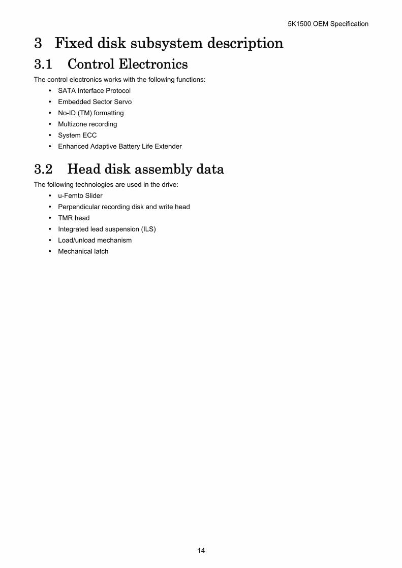
3 Fixed disk subsystem description 3.1 Control Electronics The control electronics works with the following functions:
SATA Interface Protocol
Embedded Sector Servo
No-ID (TM) formatting
Multizone recording
System ECC
Enhanced Adaptive Battery Life Extender
3.2 Head disk assembly data The following technologies are used in the drive:
u-Femto Slider
Perpendicular recording disk and write head
TMR head
Integrated lead suspension (ILS)
Load/unload mechanism
Mechanical latch
14
5K1500 OEM Specification
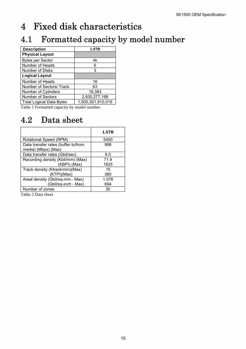
4 Fixed disk characteristics 4.1 Formatted capacity by model number Description 1.5TB
Physical Layout Bytes per Sector 4k Number of Heads 6 Number of Disks 3 Logical Layout Number of Heads 16 Number of Sectors/ Track 63 Number of Cylinders 16,383 Number of Sectors 2,930,277,168 Total Logical Data Bytes 1,500,301,910,016
Table 1 Formatted capacity by model number.
4.2 Data sheet
1.5TB
Rotational Speed (RPM) 5400 Data transfer rates (buffer to/from media) (Mbps) (Max)
998
Data transfer rates (Gbit/sec) 6.0 Recording density (Kbit/mm) (Max) (KBPI) (Max)
71.9 1825
Track density (Ktrack/mm)(Max) (KTPI)(Max)
15 380
Areal density (Gbit/sq-mm.- Max) (Gbit/sq-inch - Max)
1.076 694
Number of zones 30 Table 2 Data sheet
15
5K1500 OEM Specification
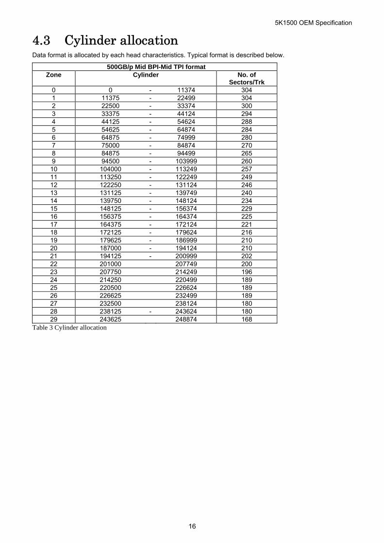
4.3 Cylinder allocation Data format is allocated by each head characteristics. Typical format is described below.
500GB/p Mid BPI-Mid TPI format Zone Cylinder No. of
Sectors/Trk 0 0 - 11374 304 1 11375 - 22499 304 2 22500 - 33374 300 3 33375 - 44124 294 4 44125 - 54624 288 5 54625 - 64874 284 6 64875 - 74999 280 7 75000 - 84874 270 8 84875 - 94499 265 9 94500 - 103999 260 10 104000 - 113249 257 11 113250 - 122249 249 12 122250 - 131124 246 13 131125 - 139749 240 14 139750 - 148124 234 15 148125 - 156374 229 16 156375 - 164374 225 17 164375 - 172124 221 18 172125 - 179624 216 19 179625 - 186999 210 20 187000 - 194124 210 21 194125 - 200999 202 22 201000 207749 200 23 207750 214249 196 24 214250 220499 189 25 220500 226624 189 26 226625 232499 189 27 232500 238124 180 28 238125 - 243624 180 29 243625 248874 168
Table 3 Cylinder allocation
16
5K1500 OEM Specification
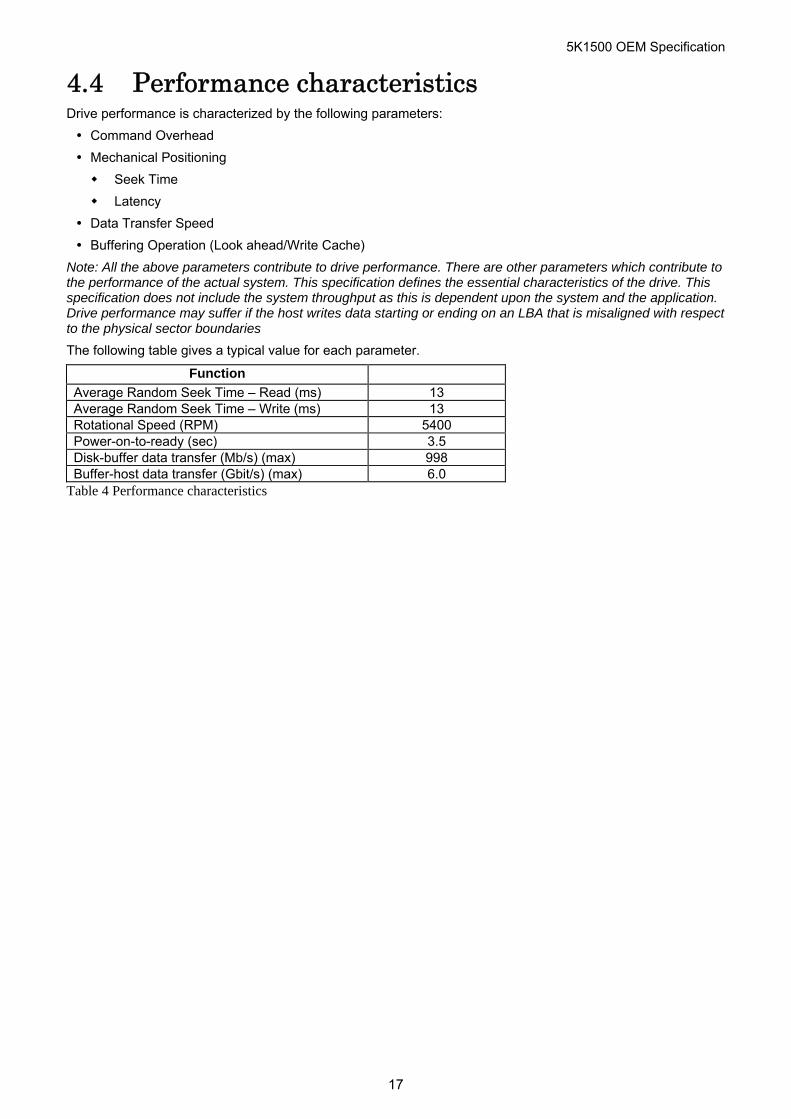
4.4 Performance characteristics Drive performance is characterized by the following parameters:
Command Overhead
Mechanical Positioning
Seek Time
Latency
Data Transfer Speed
Buffering Operation (Look ahead/Write Cache)
Note: All the above parameters contribute to drive performance. There are other parameters which contribute to the performance of the actual system. This specification defines the essential characteristics of the drive. This specification does not include the system throughput as this is dependent upon the system and the application. Drive performance may suffer if the host writes data starting or ending on an LBA that is misaligned with respect to the physical sector boundaries
The following table gives a typical value for each parameter.
Function Average Random Seek Time – Read (ms) 13 Average Random Seek Time – Write (ms) 13 Rotational Speed (RPM) 5400 Power-on-to-ready (sec) 3.5 Disk-buffer data transfer (Mb/s) (max) 998 Buffer-host data transfer (Gbit/s) (max) 6.0
Table 4 Performance characteristics
17
5K1500 OEM Specification
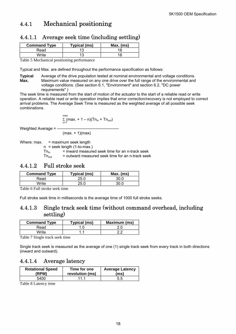
4.4.1 Mechanical positioning
4.4.1.1 Average seek time (including settling) Command Type Typical (ms) Max. (ms)
Read 13 18 Write 13 18
Table 5 Mechanical positioning performance
Typical and Max. are defined throughout the performance specification as follows:
Typical Average of the drive population tested at nominal environmental and voltage conditions. Max. Maximum value measured on any one drive over the full range of the environmental and
voltage conditions. (See section 6.1, "Environment" and section 6.2, "DC power requirements" )
The seek time is measured from the start of motion of the actuator to the start of a reliable read or write operation. A reliable read or write operation implies that error correction/recovery is not employed to correct arrival problems. The Average Seek Time is measured as the weighted average of all possible seek combinations.
max. (max. + 1 – n)(Tnin + Tnout) n=1 Weighted Average = –––––––––––––––––––––––––––– (max. + 1)(max) Where: max. = maximum seek length n = seek length (1-to-max.) Tnin = inward measured seek time for an n-track seek Tnout = outward measured seek time for an n-track seek
4.4.1.2 Full stroke seek Command Type Typical (ms) Max. (ms)
Read 25.0 30.0 Write 25.0 30.0
Table 6 Full stroke seek time
Full stroke seek time in milliseconds is the average time of 1000 full stroke seeks.
4.4.1.3 Single track seek time (without command overhead, including settling)
Command Type Typical (ms) Maximum (ms) Read 1.0 2.0 Write 1.1 2.2
Table 7 Single track seek time
Single track seek is measured as the average of one (1) single track seek from every track in both directions (inward and outward).
4.4.1.4 Average latency Rotational Speed
(RPM) Time for one
revolution (ms) Average Latency
(ms) 5400 11.1 5.5
Table 8 Latency time
18
5K1500 OEM Specification
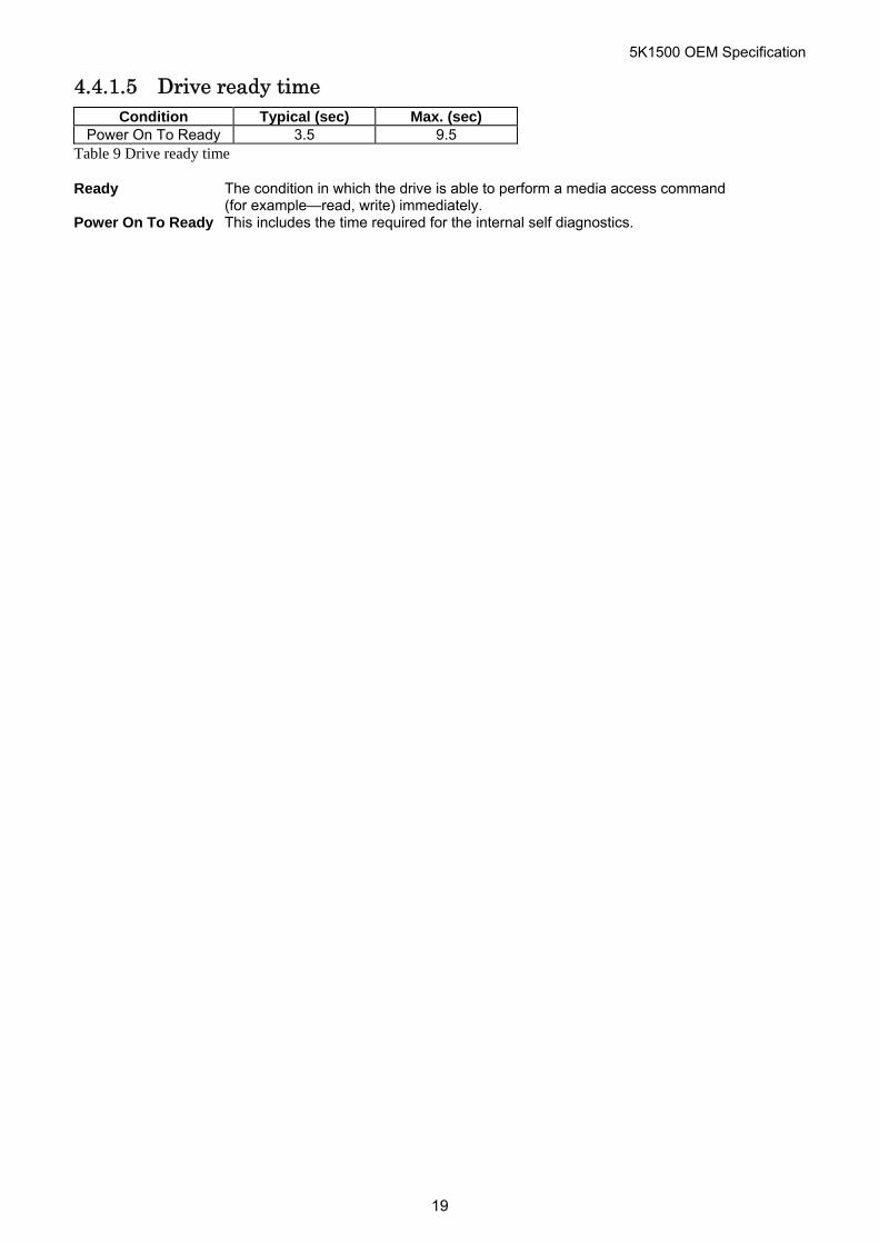
4.4.1.5 Drive ready time Condition Typical (sec) Max. (sec)
Power On To Ready 3.5 9.5 Table 9 Drive ready time
Ready The condition in which the drive is able to perform a media access command (for example—read, write) immediately.
Power On To Ready This includes the time required for the internal self diagnostics.
19
5K1500 OEM Specification
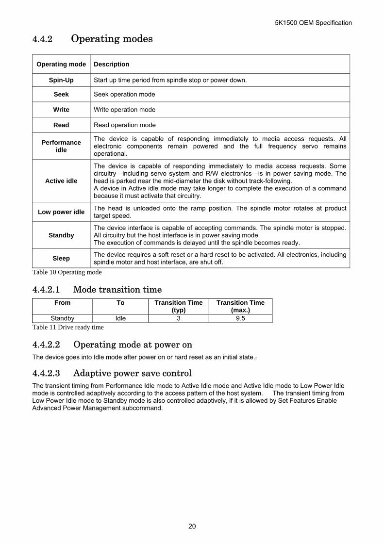
4.4.2 Operating modes
Operating mode Description
Spin-Up Start up time period from spindle stop or power down.
Seek Seek operation mode
Write Write operation mode
Read Read operation mode
Performance idle
The device is capable of responding immediately to media access requests. All electronic components remain powered and the full frequency servo remains operational.
Active idle
The device is capable of responding immediately to media access requests. Some circuitry—including servo system and R/W electronics—is in power saving mode. The head is parked near the mid-diameter the disk without track-following. A device in Active idle mode may take longer to complete the execution of a command because it must activate that circuitry.
Low power idle The head is unloaded onto the ramp position. The spindle motor rotates at product target speed.
Standby The device interface is capable of accepting commands. The spindle motor is stopped. All circuitry but the host interface is in power saving mode. The execution of commands is delayed until the spindle becomes ready.
Sleep The device requires a soft reset or a hard reset to be activated. All electronics, including spindle motor and host interface, are shut off.
Table 10 Operating mode
4.4.2.1 Mode transition time From To Transition Time
(typ) Transition Time
(max.) Standby Idle 3 9.5
Table 11 Drive ready time
4.4.2.2 Operating mode at power on The device goes into Idle mode after power on or hard reset as an initial state..
4.4.2.3 Adaptive power save control The transient timing from Performance Idle mode to Active Idle mode and Active Idle mode to Low Power Idle mode is controlled adaptively according to the access pattern of the host system. The transient timing from Low Power Idle mode to Standby mode is also controlled adaptively, if it is allowed by Set Features Enable Advanced Power Management subcommand.
20
5K1500 OEM Specification
5 Data integrity 5.1 Data loss on power off Data loss will not be caused by a power off during any operation except the write operation.
A power off during a write operation causes the loss of any received or resident data that has not been written onto the disk media.
A power off during a write operation might make a maximum of one sector of data unreadable. This state can be recovered by a rewrite operation.
5.2 Write Cache When the write cache is enabled, the write command may complete before the actual disk write operation finishes. This means that a power off, even after the write command completion, could cause the loss of data that the drive has received but not yet written onto the disk.
In order to prevent this data loss, confirm the completion of the actual write operation prior to the power off by issuing a
Soft reset
Hard reset
Flush Cache command
Standby command
Standby Immediate command
Sleep command
Confirm the command’s completion.
5.3 Equipment status The equipment status is available to the host system any time the drive is not ready to read, write, or seek. This status normally exists at the power-on time and will be maintained until the following conditions are satisfied:
The access recalibration/tuning is complete.
The spindle speed meets the requirements for reliable operation.
The self-check of the drive is complete.
The appropriate error status is made available to the host system if any of the following conditions occur after the drive has become ready:
The spindle speed lies outside the requirements for reliable operation.
The occurrence of a Write Fault condition.
5.4 WRITE safety The drive ensures that the data is written into the disk media properly. The following conditions are monitored during a write operation. When one of these conditions exceeds the criteria, the write operation is terminated and the automatic retry sequence is invoked.
Head off track
External shock
Low supply voltage
Spindle speed out of tolerance
Head open/short
21
5K1500 OEM Specification
5.5 Data buffer test The data buffer is tested at power on reset and when a drive self-test is requested by the host. The test consists of a write/read '00'x and 'ff'x pattern on all buffers.
5.6 Error recovery Errors occurring on the drive are handled by the error recovery procedure.
Errors that are uncorrectable after application of the error recovery procedure are reported to the host system as non-recoverable errors.
5.7 Automatic reallocation The sectors that show some errors may be reallocated automatically when specific conditions are met. The drive does not report any auto reallocation to the host system. The conditions for auto reallocation are described below.
5.7.1 Non-recovered write errors
When a write operation cannot be completed after the Error Recovery Procedure (ERP) is fully carried out, the sectors are reallocated to the spare location. An error is reported to the host system only when the write cache is disabled and the auto reallocation has failed.
5.7.2 Non-recoverable read error
When a read operation fails after ERP is fully carried out, a hard error is reported to the host system. This location is registered internally as a candidate for the reallocation. When a registered location is specified as a target of a write operation, a sequence of media verification is performed automatically. When the result of this verification meets the required criteria, this sector is reallocated.
5.7.3 Recovered read errors
When a read operation for a sector fails and is recovered at the specific ERP step, the sector is reallocated automatically. A media verification sequence may be run prior to the reallocation according to the predefined conditions.
22
5K1500 OEM Specification
6 Specification 6.1 Environment 6.1.1 Temperature and humidity
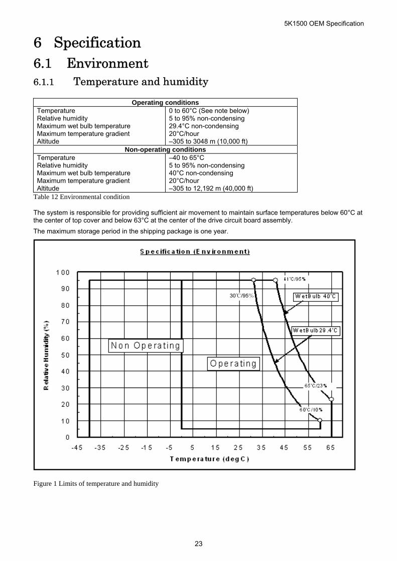
Operating conditions Temperature Relative humidity Maximum wet bulb temperature Maximum temperature gradient Altitude
0 to 60°C (See note below) 5 to 95% non-condensing 29.4°C non-condensing 20°C/hour –305 to 3048 m (10,000 ft)
Non-operating conditions Temperature Relative humidity Maximum wet bulb temperature Maximum temperature gradient Altitude
–40 to 65°C 5 to 95% non-condensing 40°C non-condensing 20°C/hour –305 to 12,192 m (40,000 ft)
Table 12 Environmental condition
The system is responsible for providing sufficient air movement to maintain surface temperatures below 60°C at the center of top cover and below 63°C at the center of the drive circuit board assembly.
The maximum storage period in the shipping package is one year.
30℃/95%
Figure 1 Limits of temperature and humidity
23
5K1500 OEM Specification
6.1.2 Corrosion test
The hard disk drive must be functional and show no signs of corrosion after being exposed to a temperature humidity stress of 50°C/90%RH (relative humidity) for one week followed by a temperature and humidty drop to 25'C/40%RH in 2 hours.
6.1.3 Radiation noise
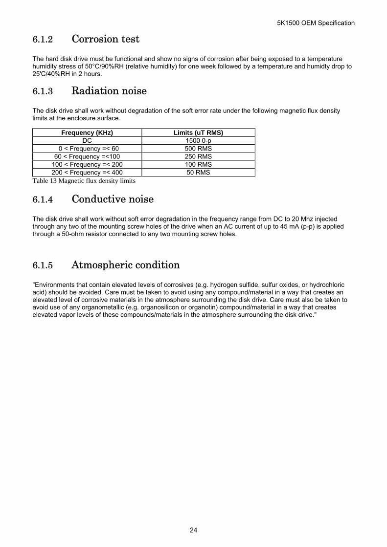
The disk drive shall work without degradation of the soft error rate under the following magnetic flux density limits at the enclosure surface.
Frequency (KHz) Limits (uT RMS) DC 1500 0-p
0 < Frequency =< 60 500 RMS 60 < Frequency =<100 250 RMS
100 < Frequency =< 200 100 RMS 200 < Frequency =< 400 50 RMS
Table 13 Magnetic flux density limits
6.1.4 Conductive noise
The disk drive shall work without soft error degradation in the frequency range from DC to 20 Mhz injected through any two of the mounting screw holes of the drive when an AC current of up to 45 mA (p-p) is applied through a 50-ohm resistor connected to any two mounting screw holes.
6.1.5 Atmospheric condition
"Environments that contain elevated levels of corrosives (e.g. hydrogen sulfide, sulfur oxides, or hydrochloric acid) should be avoided. Care must be taken to avoid using any compound/material in a way that creates an elevated level of corrosive materials in the atmosphere surrounding the disk drive. Care must also be taken to avoid use of any organometallic (e.g. organosilicon or organotin) compound/material in a way that creates elevated vapor levels of these compounds/materials in the atmosphere surrounding the disk drive."
24
5K1500 OEM Specification
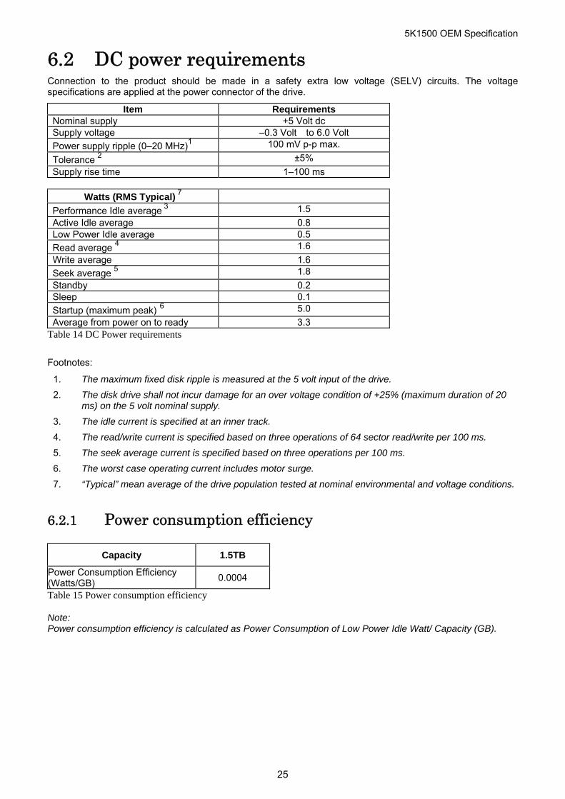
6.2 DC power requirements Connection to the product should be made in a safety extra low voltage (SELV) circuits. The voltage specifications are applied at the power connector of the drive.
Item Requirements Nominal supply +5 Volt dc Supply voltage –0.3 Volt to 6.0 Volt
Power supply ripple (0–20 MHz)1 100 mV p-p max.
Tolerance 2 ±5%
Supply rise time 1–100 ms
Watts (RMS Typical) 7
Performance Idle average 3 1.5
Active Idle average 0.8 Low Power Idle average 0.5
Read average 4 1.6
Write average 1.6
Seek average 5 1.8
Standby 0.2 Sleep 0.1
Startup (maximum peak) 6 5.0
Average from power on to ready 3.3 Table 14 DC Power requirements
Footnotes:
1. The maximum fixed disk ripple is measured at the 5 volt input of the drive.
2. The disk drive shall not incur damage for an over voltage condition of +25% (maximum duration of 20 ms) on the 5 volt nominal supply.
3. The idle current is specified at an inner track.
4. The read/write current is specified based on three operations of 64 sector read/write per 100 ms.
5. The seek average current is specified based on three operations per 100 ms.
6. The worst case operating current includes motor surge.
7. “Typical” mean average of the drive population tested at nominal environmental and voltage conditions.
6.2.1 Power consumption efficiency
Capacity 1.5TB
Power Consumption Efficiency (Watts/GB)
0.0004
Table 15 Power consumption efficiency
Note: Power consumption efficiency is calculated as Power Consumption of Low Power Idle Watt/ Capacity (GB).
25
5K1500 OEM Specification
6.3 Reliability 6.3.1 Data reliability
Probability of not recovering data is 1 in 1014 bits read
LDPC implementation
Offline erasure correction performed recovers up to 3320 bits of errors in 1 sector.
6.3.2 Failure prediction (S.M.A.R.T.)
The drive supports Self-monitoring, analysis and reporting technology (S.M.A.R.T.) function. The details are described in section 12.8, "S.M.A.R.T. Function" and in Section 14.41, "S.M.A.R.T. Function Set (B0h)"
6.3.3 Cable noise interference
To avoid any degradation of performance throughput or error when the interface cable is routed on top or comes in contact with the HDA assembly, the drive must be grounded electrically to the system frame by four screws. The common mode noise or voltage level difference between the system frame and power cable ground or AT interface cable ground should be in the allowable level specified in the power requirement section.
6.3.4 Service life and usage condition
The drive is designed to be used under the following conditions:
The drive should be operated within specifications of shock, vibration, temperature, humidity, altitude, and magnetic field.
The drive should be protected from ESD.
The breathing hole in the top cover of the drive should not be covered.
Force should not be applied to the cover of the drive.
The specified power requirements of the drive should be satisfied.
The drive frame should be grounded electrically to the system through four screws.
The drive should be mounted with the recommended screw depth and torque.
The interface physical and electrical requirements of the drive should satisfy Serial ATA Revision 3.0.
The power-off sequence of the drive should comply with the 6.3.6.2,"Required power-off sequence.”
Service life of the drive is approximately 5 years or 20,000 power on hours, whichever comes first, under the following assumptions:
Less than 333 power on hours per month.
Seeking/Writing/Reading operation is less than 20% of power on hours.
This does not represent any warranty or warranty period. Applicable warranty and warranty period are covered by the purchase agreement.
6.3.5 Preventive maintenance
None.
26
5K1500 OEM Specification
6.3.6 Load/unload
The product supports a minimum of 600,000 normal load/unloads.
Load/unload is a functional mechanism of the hard disk drive. It is controlled by the drive micro code. Specifically, unloading of the heads is invoked by the following commands:
Standby
Standby immediate
Sleep
Load/unload is also invoked as one of the idle modes of the drive.
The specified start/stop life of the product assumes that load/unload is operated normally, not in emergency mode.
6.3.6.1 Emergency unload When hard disk drive power is interrupted while the heads are still loaded the micro code cannot operate and the normal 5-volt power is unavailable to unload the heads. In this case, normal unload is not possible. The heads are unloaded by routing the back EMF of the spinning motor to the voice coil. The actuator velocity is greater than the normal case and the unload process is inherently less controllable without a normal seek current profile.
Emergency unload is intended to be invoked in rare situations. Because this operation is inherently uncontrolled, it is more mechanically stressful than a normal unload.
The drive supports a minimum of 20,000 emergency unloads.
6.3.6.2 Required Power-Off Sequence The required host system sequence for removing power from the drive is as follows:
Step 1: Issue one of the following commands.
Standby
Standby immediate
Sleep
Note: Do not use the Flush Cache command for the power off sequence because this command does not invoke Unload.
Step 2: Wait until the Command Complete status is returned.
The host system time out value needs to be 30 seconds considering error recovery time.
Step 3: Terminate power to HDD.
This power-down sequence should be followed for entry into any system power-down state, system suspend state, or system hibernation state. In a robustly designed system, emergency unload is limited to rare scenarios, such as battery removal during operation.
6.3.6.3 Power switch design considerations In systems that use the Travelstar 5K1500 consideration should be given to the design of the system power switch.
HGST recommends that the switch operate under control of the host system, as opposed to being hardwired. The same recommendation is made for cover-close switches. When a hardwired switch is turned off, emergency unload occurs, as well as the problems cited in section 5.1, "Data loss by power off" and section 5.2, “Write Cache”.
27
5K1500 OEM Specification
6.3.6.4 Test considerations Start/stop testing is classically performed to verify head/disk durability. The heads do not land on the disk, so this type of test should be viewed as a test of the load/unload function.
Start/Stop testing should be done by commands through the interface, not by power cycling the drive. Simple power cycling of the drive invokes the emergency unload mechanism and subjects the HDD to non-typical mechanical stress.
Power cycling testing may be required to test the boot-up function of the system. In this case HGST recommends that the power-off portion of the cycle contain the sequence specified in section 6.3.6.2, "Required Power-Off Sequence”. If this is not done, the emergency unload function is invoked and non-typical stress results.
28
5K1500 OEM Specification
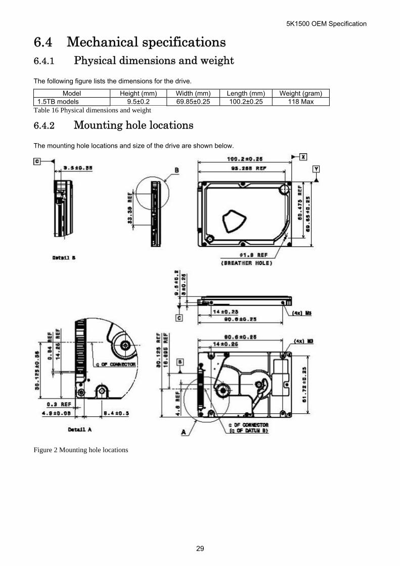
6.4 Mechanical specifications 6.4.1 Physical dimensions and weight
The following figure lists the dimensions for the drive.
Model Height (mm) Width (mm) Length (mm) Weight (gram) 1.5TB models 9.5±0.2 69.85±0.25 100.2±0.25 118 Max
Table 16 Physical dimensions and weight
6.4.2 Mounting hole locations
The mounting hole locations and size of the drive are shown below.
Figure 2 Mounting hole locations
29
5K1500 OEM Specification
6.4.3 Connector description
Connector specifications are included in section 7.2, "Interface connector".
6.4.4 Mounting orientation
The drive will operate in all axes (six directions). Performance and error rate will stay within specification limits if the drive is operated in the other permissible orientations from which it was formatted. Thus a drive formatted in a horizontal orientation will be able to run vertically and vice versa.
The recommended mounting screw torque is 0.3±0.05 Nm.
The recommended mounting screw depth is 3.0±0.3 mm for bottom and 3.5±0.5 mm for horizontal mounting.
The user is responsible for using the appropriate screws or equivalent mounting hardware to mount the drive securely enough to prevent excessive motion or vibration of the drive at seek operation or spindle rotation.
6.4.5 Load/unload mechanism
The head load/unload mechanism is provided to protect the disk data during shipping, movement, or storage. Upon power down, a head unload mechanism secures the heads at the unload position. See section 6.5.4, "Non-operating shock" for additional details.
30
5K1500 OEM Specification
6.5 Vibration and shock All vibration and shock measurements in this section are for drives without mounting attachments for systems. The input level shall be applied to the normal drive mounting points.
Vibration tests and shock tests are to be conducted by mounting the drive to a table using the bottom or side four mounting holes.
6.5.1 Operating vibration
The drive will operate without a hard error while being subjected to the following vibration levels.
6.5.1.1 Random vibration The test consists of 30 minutes of random vibration using the power spectral density (PSD) levels below.
The vibration test level is 6.57m/sec2 RMS (Root Mean Square) (0.67 G RMS).
Random vibration PSD profile Breakpoint Hz m x 10n (m2/sec4)/Hz 5 1.9 x E–3 17 1.1 x E–1 45 1.1 x E–1 48 7.7 x E–1 62 7.7 x E–1 65 9.6 x E–2
150 9.6 x E–2 200 4.8 x E–2 500 4.8 x E–2
Table 17 Random vibration PSD profile breakpoints (operating)
6.5.1.2 Swept sine vibration Swept sine vibration (zero to peak 5 to 500 to 5 Hz sine wave)
Sweep rate (oct/min)
9.8 m/sec2 (1 G) (5-500 Hz) 1.0
Table 18 Swept sine vibration
31
5K1500 OEM Specification
6.5.2 Non-operating vibration
The disk drive withstands the following vibration levels without any loss or permanent damage.
6.5.2.1 Random vibration The test consists of a random vibration applied in each of three mutually perpendicular axes for duration of 15 minutes per axis. The PSD levels for the test simulating the shipping and relocation environment is shown below.
Hz (m2/sec4)/Hz 2.5 0.096 5 2.88 40 1.73
500 1.73 Table 19 Random Vibration PSD Profile Breakpoints (non-operating)
Note: Overall RMS level of vibration is 29.50 m/sec2 (3.01 G).
6.5.2.2 Swept sine vibration 49 m/sec2 (5 G) (zero-to-peak), 10 to 500 to 10 Hz sine wave
0.5 oct/min sweep rate
25.4 mm (peak-to-peak) displacement, 5 to 10 to 5 Hz
6.5.3 Operating shock
The hard disk drive meets the criteria in the table below while operating under these conditions:
The shock test consists of 10 shock inputs in each axis and direction for a total of 60.
There must be a minimum delay of 3 seconds between shock pulses.
The disk drive will operate without a hard error while subjected to the following half-sine shock pulse.
Duration of 1 ms Duration of 2 ms
2205 m/sec2 (225 G) 3920 m/sec2 (400 G) Table 20 Operating shock
The input level shall be applied to the normal disk drive subsystem mounting points used to secure the drive in a normal system.
6.5.4 Non-operating shock
The drive withstands the following half-sine shock pulse without any data loss or permanent damage.
Duration of 1 ms Duration of 11 ms
9800 m/sec2 (1000 G) 1470 m/sec2 (150 G) Table 21 Non-operating shock
The shocks are applied for each direction of the drive for three mutually perpendicular axes, one axis at a time. Input levels are measured on a base plate where the drive is attached with four screws.
32
5K1500 OEM Specification
6.6 Acoustics 6.6.1 Sound power level
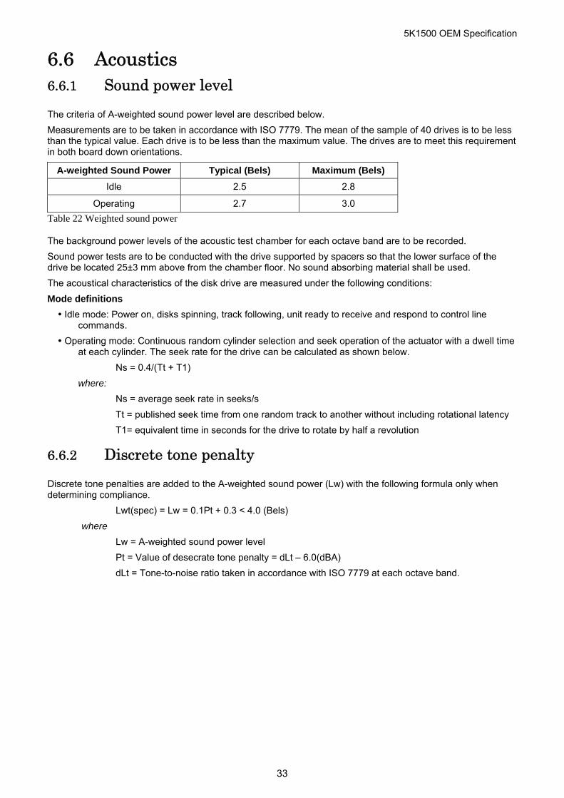
The criteria of A-weighted sound power level are described below.
Measurements are to be taken in accordance with ISO 7779. The mean of the sample of 40 drives is to be less than the typical value. Each drive is to be less than the maximum value. The drives are to meet this requirement in both board down orientations.
A-weighted Sound Power Typical (Bels) Maximum (Bels)
Idle 2.5 2.8
Operating 2.7 3.0
Table 22 Weighted sound power
The background power levels of the acoustic test chamber for each octave band are to be recorded.
Sound power tests are to be conducted with the drive supported by spacers so that the lower surface of the drive be located 25±3 mm above from the chamber floor. No sound absorbing material shall be used.
The acoustical characteristics of the disk drive are measured under the following conditions:
Mode definitions
Idle mode: Power on, disks spinning, track following, unit ready to receive and respond to control line commands.
Operating mode: Continuous random cylinder selection and seek operation of the actuator with a dwell time at each cylinder. The seek rate for the drive can be calculated as shown below.
Ns = 0.4/(Tt + T1)
where:
Ns = average seek rate in seeks/s
Tt = published seek time from one random track to another without including rotational latency
T1= equivalent time in seconds for the drive to rotate by half a revolution
6.6.2 Discrete tone penalty
Discrete tone penalties are added to the A-weighted sound power (Lw) with the following formula only when determining compliance.
Lwt(spec) = Lw = 0.1Pt + 0.3 < 4.0 (Bels)
where
Lw = A-weighted sound power level
Pt = Value of desecrate tone penalty = dLt – 6.0(dBA)
dLt = Tone-to-noise ratio taken in accordance with ISO 7779 at each octave band.
33
5K1500 OEM Specification
6.7 Identification labels The following labels are affixed to every drive:
A label which is placed on the top of the head disk assembly containing the statement "Made by HGST" or equivalent, part number
A bar code label which is placed on the disk drive based on user request. The location on the disk drive is to be designated in the drawing provided by the user.
Labels containing the vendor's name, disk drive model number, serial number, place of manufacture, and UL/CSA logos.
6.8 Electromagnetic compatibility When installed in a suitable enclosure and exercised with a random accessing routine at maximum data rate, the drive meets the following worldwide electromagnetic compatibility (EMC) requirements:
United States Federal Communications Commission (FCC) Rules and Regulations (Class B), Part 15. RFI Suppression German National Requirements
RFI Japan VCCI, Requirements of HGST products
EU EMC Directive, Technical Requirements and Conformity Assessment Procedures
6.8.1 CE Mark
The product is certified for compliance with EC directive 2004/108/EC. The EC marking for the certification appears on the drive.
6.8.2 C-Tick Mark
The product complies with the Australian EMC standard "Limits and methods of measurement of radio disturbance characteristics of information technology equipment, AS/NZS 3548:1995 Class B."
6.8.3 BSMI Mark
The product complies with the Taiwan EMC standard “Limits and methods of measurement of radio disturbance characteristics of information technology equipment, CNS 13438 (C6357)”
6.8.4 KC Mark
The product complies with the Korea EMC standard. The regulation for certification of information and communication equipment is based on “Telecommunications Basic Act” and “Radio Waves Act” Korea EMC requirement are based technically on CISPR22 measurement standards and limits. The standards are likewise based on IEC standards.
34
5K1500 OEM Specification
6.9 Safety 6.9.1 UL and CSA approval
All models of the Travelstar 5K1500 are qualified per UL60950-1:2nd edition (2007-03-27),
CSA C22.2 No.60950-1-07:2nd edition (2007-03)
6.9.2 IEC compliance
All models of the Travelstar 5K1500 comply with IEC 60950-1: 2005 (2nd edition).
6.9.3 German Safety Mark
All models of the Travelstar 5K1500 are approved by TUV on Test Requirement: EN 60950-1:2006+A11,, but the GS mark has not been obtained.
6.9.4 Flammability
The printed circuit boards used in this product are made of material with a UL recognized flammability rating of V-1 or better. The flammability rating is marked or etched on the board. All other parts not considered electrical components are made of material with a UL recognized flammability rating of V-1 or better except minor mechanical parts.
6.9.5 Secondary circuit protection
This product utilizes printed circuit wiring that must be protected against the possibility of sustained combustion due to circuit or component failures as defined in C-B 2-4700-034 (Protection Against Combustion). Adequate secondary over current protection is the responsibility of the using system.
The user must protect the drive from its electrical short circuit problem. 10 amp limit is required for safety purpose.
6.10 Packaging Drives are packed in ESD protective bags and shipped in appropriate containers.
6.11 Substance restriction requirements The product complies with the Directive 2002/95/EC of the European Parliament on the restrictions of the use of the certain hazardous substances in electrical and electronic equipment (RoHS).
35
5K1500 OEM Specification
7 Electrical interface specifications 7.1 Cabling The maximum cable length from the host system to the hard disk drive plus circuit pattern length in the host system shall not exceed 1 meter.
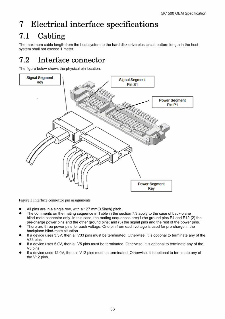
7.2 Interface connector The figure below shows the physical pin location.
Figure 3 Interface connector pin assignments
All pins are in a single row, with a 127 mm(0.5inch) pitch. The comments on the mating sequence in Table in the section 7.3 apply to the case of back-plane
blind-mate connector only. In this case, the mating sequences are:(1)the ground pins P4 and P12;(2) the pre-charge power pins and the other ground pins; and (3) the signal pins and the rest of the power pins.
There are three power pins for each voltage. One pin from each voltage is used for pre-charge in the backplane blind-mate situation.
If a device uses 3.3V, then all V33 pins must be terminated. Otherwise, it is optional to terminate any of the V33 pins
If a device uses 5.0V, then all V5 pins must be terminated. Otherwise, it is optional to terminate any of the V5 pins
If a device uses 12.0V, then all V12 pins must be terminated. Otherwise, it is optional to terminate any of the V12 pins.
36
5K1500 OEM Specification
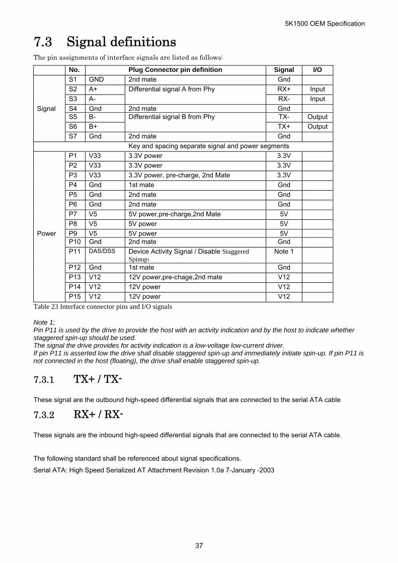
7.3 Signal definitions The pin assignments of interface signals are listed as follows:
No. Plug Connector pin definition Signal I/O
S1 GND 2nd mate Gnd
S2 A+ Differential signal A from Phy RX+ Input
S3 A- RX- Input
Signal S4 Gnd 2nd mate Gnd
S5 B- Differential signal B from Phy TX- Output
S6 B+ TX+ Output
S7 Gnd 2nd mate Gnd Key and spacing separate signal and power segments P1 V33 3.3V power 3.3V P2 V33 3.3V power 3.3V
P3 V33 3.3V power, pre-charge, 2nd Mate 3.3V
P4 Gnd 1st mate Gnd
P5 Gnd 2nd mate Gnd
P6 Gnd 2nd mate Gnd
P7 V5 5V power,pre-charge,2nd Mate 5V
P8 V5 5V power 5V
Power P9 V5 5V power 5V
P10 Gnd 2nd mate Gnd
P11 DAS/DSS
Device Activity Signal / Disable Staggered Spinup1
Note 1
P12 Gnd 1st mate Gnd
P13 V12 12V power,pre-chage,2nd mate V12
P14 V12 12V power V12
P15 V12 12V power V12
Table 23 Interface connector pins and I/O signals
Note 1; Pin P11 is used by the drive to provide the host with an activity indication and by the host to indicate whether staggered spin-up should be used. The signal the drive provides for activity indication is a low-voltage low-current driver. If pin P11 is asserted low the drive shall disable staggered spin-up and immediately initiate spin-up. If pin P11 is not connected in the host (floating), the drive shall enable staggered spin-up.
7.3.1 TX+ / TX-
These signal are the outbound high-speed differential signals that are connected to the serial ATA cable
7.3.2 RX+ / RX-
These signals are the inbound high-speed differential signals that are connected to the serial ATA cable.
The following standard shall be referenced about signal specifications.
Serial ATA: High Speed Serialized AT Attachment Revision 1.0a 7-January -2003
37
5K1500 OEM Specification
38
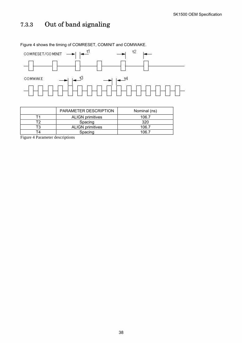
7.3.3 Out of band signaling
Figure 4 shows the timing of COMRESET, COMINIT and COMWAKE.
PARAMETER DESCRIPTION Nominal (ns)
T1 ALIGN primitives 106.7 T2 Spacing 320 T3 ALIGN primitives 106.7 T4 Spacing 106.7
Figure 4 Parameter descriptions
5K1500 OEM Specification
Part 2 Interface Specification
39
5K1500 OEM Specification
8 General 8.1 Introduction This specification describes the host interface of HTS5415XXA9X6XX.
The interface conforms to following Working Document of Information technology with certain limitations described in the chapter 9 “Deviations from Standard” .
Serial ATA International Organization: Serial ATA Revision 3.0 dated on 27 May 2009
AT Attachment 8 – ATA/ATAPI Command Set (ATA8-ACS) Revision 3f dated on 11 December 2006
HTS5415XXA9X6XX supports following vendor-specific functions.
Format Unit Function SENSE CONDITION command
8.2 Terminology Device Device indicates HTS5415XXA9X6XX Host Host indicates the system that the device is attached to. INTRQ Interrupt request (Device or Host)
9 Deviations from Standard The device conforms to the referenced specifications, with deviations described below.
The interface conforms to the Working Document of Information Technology, AT Attachment 8 – ATA/ATAPI Command Set (ATA/ATAPI8-ACS) with deviation as follows:
S.M.A.R.T. Return Status S.M.A.R.T. RETURN STATUS subcommand does not check advisory attributes. That is, the device will not report threshold exceeded condition unless pre-failure attributes exceed their corresponding thresholds. For example, Power-On Hours Attribute never results in negative reliability status.
Check Power Mode Check Power Mode command returns Ffh to Sector Count Register when the device is in Idle mode. This command does not support 80h as the return value.
10 Physical Interface Physical Interface is described in Functional Specification part.
40
5K1500 OEM Specification
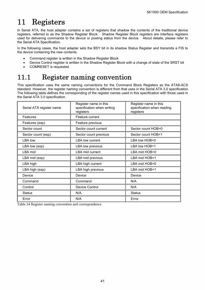
11 Registers In Serial ATA, the host adapter contains a set of registers that shadow the contents of the traditional device registers, referred to as the Shadow Register Block. Shadow Register Block registers are interface registers used for delivering commands to the device or posting status from the device. About details, please refer to the Serial ATA Specification.
In the following cases, the host adapter sets the BSY bit in its shadow Status Register and transmits a FIS to the device containing the new contents.
Command register is written in the Shadow Register Block Device Control register is written in the Shadow Register Block with a change of state of the SRST bit COMRESET is requested
11.1 Register naming convention This specification uses the same naming conventions for the Command Block Registers as the ATA8-ACS standard. However, the register naming convention is different from that uses in the Serial ATA 3.0 specification. The following table defines the corresponding of the register names used in this specification with those used in the Serial ATA 3.0 specification.
Serial ATA register name Register name in this specification when writing registers
Register name in this specification when reading registers
Features Feature current
Features (exp) Feature previous
Sector count Sector count current Sector count HOB=0
Sector count (exp) Sector count previous Sector count HOB=1
LBA low LBA low current LBA low HOB=0
LBA low (exp) LBA low previous LBA low HOB=1
LBA mid LBA mid current LBA mid HOB=0
LBA mid (exp) LBA mid previous LBA mid HOB=1
LBA high LBA high current LBA mid HOB=0
LBA high (exp) LBA high previous LBA mid HOB=1
Device Device Device
Command Command N/A
Control Device Control N/A
Status N/A Status
Error N/A Error
Table 24 Register naming convention and correspondence
41
5K1500 OEM Specification
11.2 Command register This register contains the command code being sent to the device. Command execution begins immediately after this register is written. The command set is shown in “Table 43 Command set” on page 74.
All other registers required for the command must be set up before writing the Command Register.
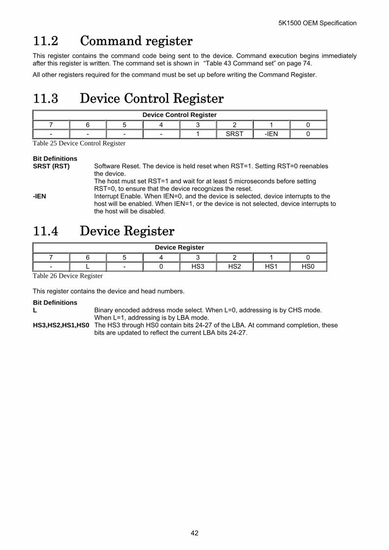
11.3 Device Control Register Device Control Register
7 6 5 4 3 2 1 0 - - - - 1 SRST -IEN 0
Table 25 Device Control Register
Bit Definitions SRST (RST) Software Reset. The device is held reset when RST=1. Setting RST=0 reenables
the device. The host must set RST=1 and wait for at least 5 microseconds before setting RST=0, to ensure that the device recognizes the reset.
-IEN Interrupt Enable. When IEN=0, and the device is selected, device interrupts to the host will be enabled. When IEN=1, or the device is not selected, device interrupts to the host will be disabled.
11.4 Device Register Device Register
7 6 5 4 3 2 1 0 - L - 0 HS3 HS2 HS1 HS0
Table 26 Device Register
This register contains the device and head numbers.
Bit Definitions L Binary encoded address mode select. When L=0, addressing is by CHS mode.
When L=1, addressing is by LBA mode. HS3,HS2,HS1,HS0 The HS3 through HS0 contain bits 24-27 of the LBA. At command completion, these
bits are updated to reflect the current LBA bits 24-27.
42
5K1500 OEM Specification
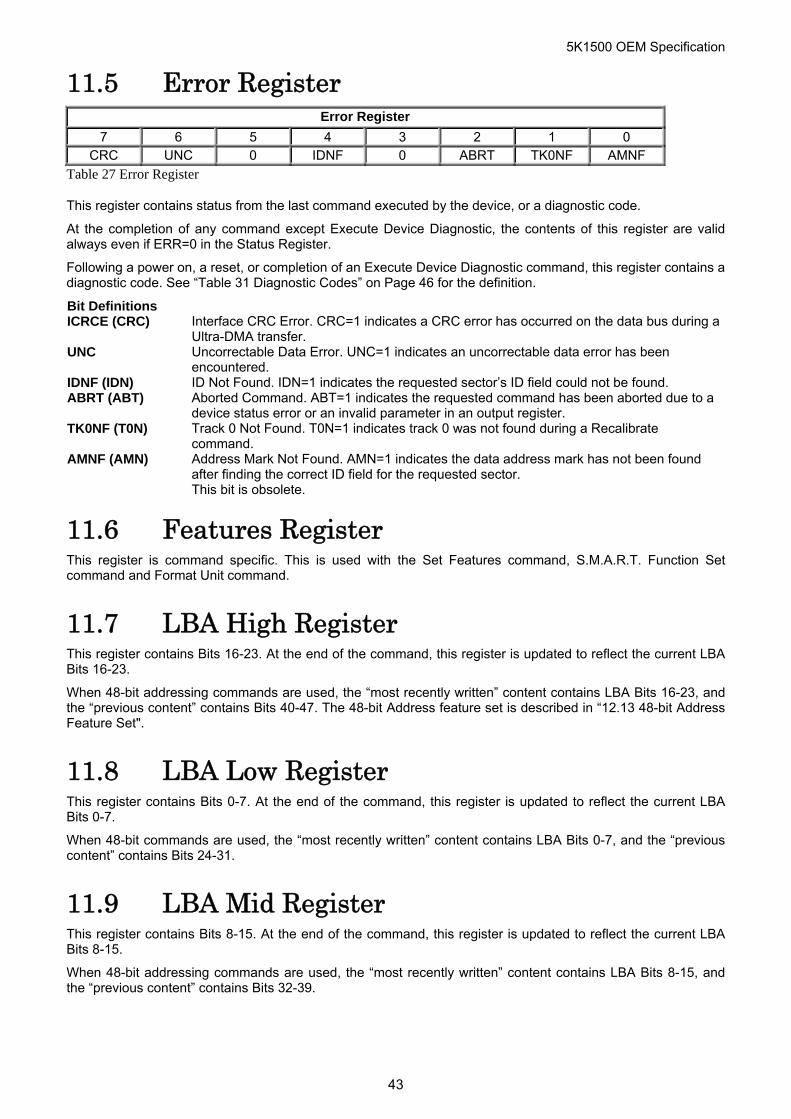
11.5 Error Register Error Register
7 6 5 4 3 2 1 0 CRC UNC 0 IDNF 0 ABRT TK0NF AMNF
Table 27 Error Register
This register contains status from the last command executed by the device, or a diagnostic code.
At the completion of any command except Execute Device Diagnostic, the contents of this register are valid always even if ERR=0 in the Status Register.
Following a power on, a reset, or completion of an Execute Device Diagnostic command, this register contains a diagnostic code. See “Table 31 Diagnostic Codes” on Page 46 for the definition.
Bit Definitions ICRCE (CRC) Interface CRC Error. CRC=1 indicates a CRC error has occurred on the data bus during a
Ultra-DMA transfer. UNC Uncorrectable Data Error. UNC=1 indicates an uncorrectable data error has been
encountered. IDNF (IDN) ID Not Found. IDN=1 indicates the requested sector’s ID field could not be found. ABRT (ABT) Aborted Command. ABT=1 indicates the requested command has been aborted due to a
device status error or an invalid parameter in an output register. TK0NF (T0N) Track 0 Not Found. T0N=1 indicates track 0 was not found during a Recalibrate
command. AMNF (AMN) Address Mark Not Found. AMN=1 indicates the data address mark has not been found
after finding the correct ID field for the requested sector. This bit is obsolete.
11.6 Features Register This register is command specific. This is used with the Set Features command, S.M.A.R.T. Function Set command and Format Unit command.
11.7 LBA High Register This register contains Bits 16-23. At the end of the command, this register is updated to reflect the current LBA Bits 16-23.
When 48-bit addressing commands are used, the “most recently written” content contains LBA Bits 16-23, and the “previous content” contains Bits 40-47. The 48-bit Address feature set is described in “12.13 48-bit Address Feature Set".
11.8 LBA Low Register This register contains Bits 0-7. At the end of the command, this register is updated to reflect the current LBA Bits 0-7.
When 48-bit commands are used, the “most recently written” content contains LBA Bits 0-7, and the “previous content” contains Bits 24-31.
11.9 LBA Mid Register This register contains Bits 8-15. At the end of the command, this register is updated to reflect the current LBA Bits 8-15.
When 48-bit addressing commands are used, the “most recently written” content contains LBA Bits 8-15, and the “previous content” contains Bits 32-39.
43
5K1500 OEM Specification
11.10 Sector Count Register This register contains the number of sectors of data requested to be transferred on a read or write operation between the host and the device. If the value in the register is set to 0, a count of 256 sectors (in 28-bit addressing) or 65,536 sectors (in 48-bit addressing) is specified.
If the register is zero at command completion, the command was successful. If not successfully completed, the register contains the number of sectors which need to be transferred in order to complete the request.
The contents of the register are defined otherwise on some commands. These definitions are given in the command descriptions.
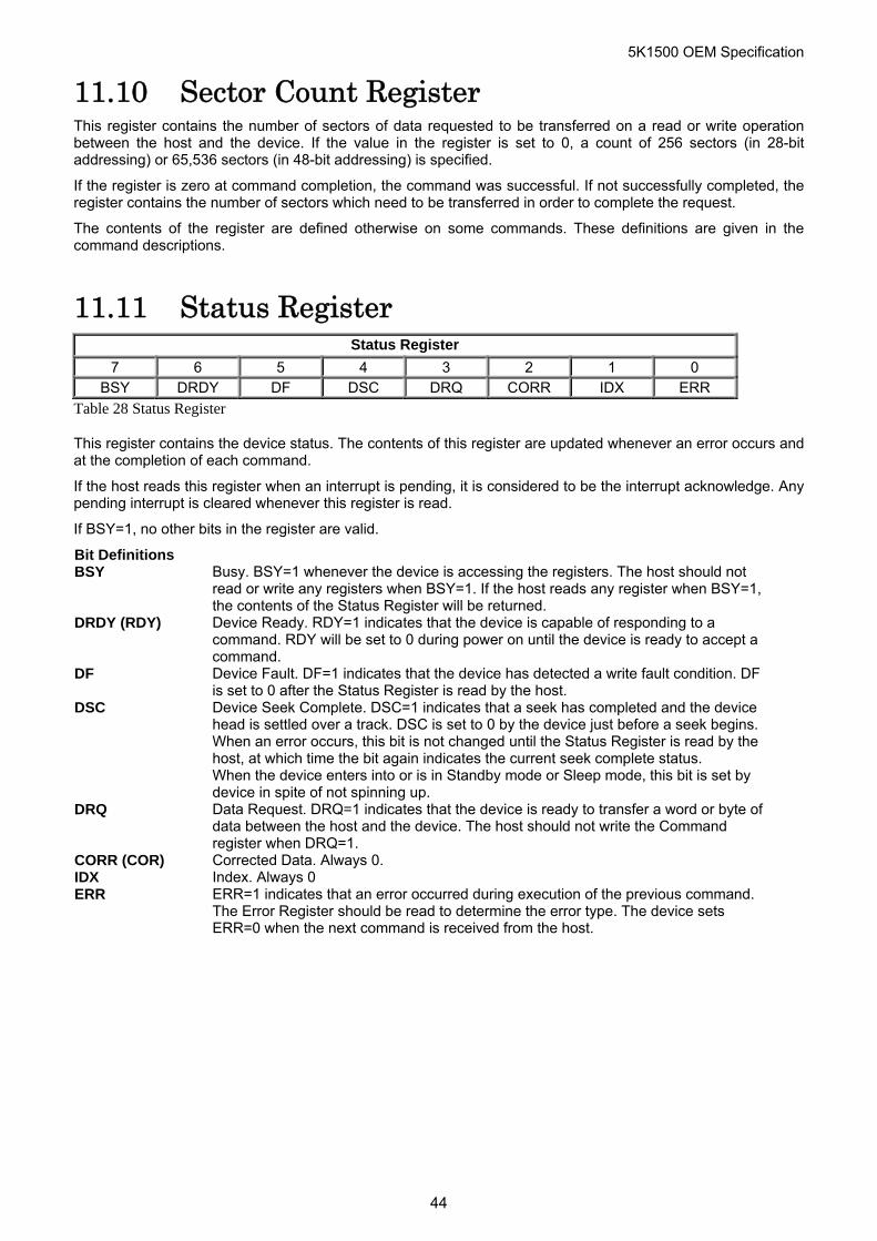
11.11 Status Register Status Register
7 6 5 4 3 2 1 0 BSY DRDY DF DSC DRQ CORR IDX ERR
Table 28 Status Register
This register contains the device status. The contents of this register are updated whenever an error occurs and at the completion of each command.
If the host reads this register when an interrupt is pending, it is considered to be the interrupt acknowledge. Any pending interrupt is cleared whenever this register is read.
If BSY=1, no other bits in the register are valid.
Bit Definitions BSY Busy. BSY=1 whenever the device is accessing the registers. The host should not
read or write any registers when BSY=1. If the host reads any register when BSY=1, the contents of the Status Register will be returned.
DRDY (RDY) Device Ready. RDY=1 indicates that the device is capable of responding to a command. RDY will be set to 0 during power on until the device is ready to accept a command.
DF Device Fault. DF=1 indicates that the device has detected a write fault condition. DF is set to 0 after the Status Register is read by the host.
DSC Device Seek Complete. DSC=1 indicates that a seek has completed and the device head is settled over a track. DSC is set to 0 by the device just before a seek begins. When an error occurs, this bit is not changed until the Status Register is read by the host, at which time the bit again indicates the current seek complete status. When the device enters into or is in Standby mode or Sleep mode, this bit is set by device in spite of not spinning up.
DRQ Data Request. DRQ=1 indicates that the device is ready to transfer a word or byte of data between the host and the device. The host should not write the Command register when DRQ=1.
CORR (COR) Corrected Data. Always 0. IDX Index. Always 0 ERR ERR=1 indicates that an error occurred during execution of the previous command.
The Error Register should be read to determine the error type. The device sets ERR=0 when the next command is received from the host.
44
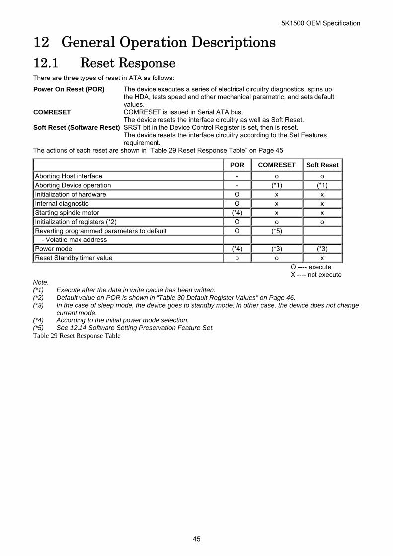
5K1500 OEM Specification
12 General Operation Descriptions 12.1 Reset Response There are three types of reset in ATA as follows:
Power On Reset (POR) The device executes a series of electrical circuitry diagnostics, spins up the HDA, tests speed and other mechanical parametric, and sets default values.
COMRESET COMRESET is issued in Serial ATA bus. The device resets the interface circuitry as well as Soft Reset.
Soft Reset (Software Reset) SRST bit in the Device Control Register is set, then is reset. The device resets the interface circuitry according to the Set Features requirement.
The actions of each reset are shown in “Table 29 Reset Response Table” on Page 45
POR COMRESET Soft Reset
Aborting Host interface - o o Aborting Device operation - (*1) (*1) Initialization of hardware O x x Internal diagnostic O x x Starting spindle motor (*4) x x Initialization of registers (*2) O o o Reverting programmed parameters to default O (*5) - Volatile max address Power mode (*4) (*3) (*3) Reset Standby timer value o o x
O ---- execute X ---- not execute
Note. (*1) Execute after the data in write cache has been written. (*2) Default value on POR is shown in “Table 30 Default Register Values” on Page 46. (*3) In the case of sleep mode, the device goes to standby mode. In other case, the device does not change
current mode. (*4) According to the initial power mode selection. (*5) See 12.14 Software Setting Preservation Feature Set. Table 29 Reset Response Table
45
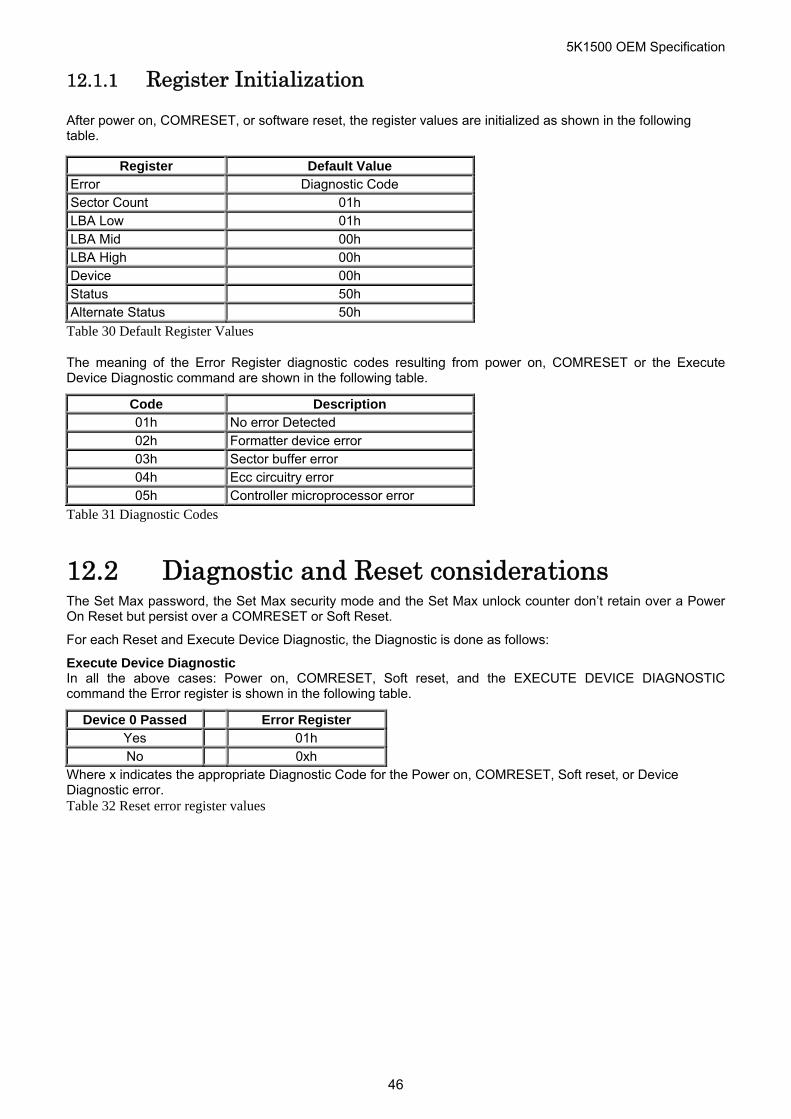
5K1500 OEM Specification
12.1.1 Register Initialization
After power on, COMRESET, or software reset, the register values are initialized as shown in the following table.
Register Default Value Error Diagnostic Code Sector Count 01h LBA Low 01h LBA Mid 00h LBA High 00h Device 00h Status 50h Alternate Status 50h
Table 30 Default Register Values
The meaning of the Error Register diagnostic codes resulting from power on, COMRESET or the Execute Device Diagnostic command are shown in the following table.
Code Description 01h No error Detected 02h Formatter device error 03h Sector buffer error 04h Ecc circuitry error 05h Controller microprocessor error
Table 31 Diagnostic Codes
12.2 Diagnostic and Reset considerations The Set Max password, the Set Max security mode and the Set Max unlock counter don’t retain over a Power On Reset but persist over a COMRESET or Soft Reset.
For each Reset and Execute Device Diagnostic, the Diagnostic is done as follows:
Execute Device Diagnostic In all the above cases: Power on, COMRESET, Soft reset, and the EXECUTE DEVICE DIAGNOSTIC command the Error register is shown in the following table.
Device 0 Passed Error Register Yes 01h No 0xh
Where x indicates the appropriate Diagnostic Code for the Power on, COMRESET, Soft reset, or Device Diagnostic error. Table 32 Reset error register values
46
5K1500 OEM Specification
12.3 Power-off considerations 12.3.1 Load/Unload
Load/Unload is a functional mechanism of the HDD. It is controlled by the drive microcode. Specifically, unloading of the heads is invoked by the commands:
Command Response Standby UL -> Comp. Standby immediate UL -> Comp. Sleep UL -> Comp.
“UL” means “unload”. “Comp” means “complete”.
Table 33 Device’s behavior by ATA commands
Load/unload is also invoked as one of the idle modes of the drive.
The specified start/stop life of the product assumes that load/unload is operated normally, NOT in emergency mode.
12.3.2 Emergency unload
When HDD power is interrupted while the heads are still loaded, the microcode cannot operate and the normal 5V power is unavailable to unload the heads. In this case, normal unload is not possible, so the heads are unloaded by routing the back-EMF of the spinning motor to the voice coil. The actuator velocity is greater than the normal case, and the unload process is inherently less controllable without a normal seek current profile.
Emergency unload is intended to be invoked in rare situations. Because this operation is inherently uncontrolled, it is more mechanically stressful than a normal unload.
A single emergency unload operation is more stressful than 100 normal unloads. Use of emergency unload reduces the start/stop life of the HDD at a rate at least 100X faster than that of normal unload, and may damage the HDD.
12.3.3 Required power-off sequence
Problems can occur on most HDDs when power is removed at an arbitrary time. Examples:
Data loss from the write buffer. If the drive is writing a sector, the sector contents are destroyed and reading that sector results in a
hard error. You may then turn off the HDD in the following order:
1. Issue Standby, Standby Immediate or sleep command. 2. Wait until COMMAND COMPLETE STATUS is returned. 3. Terminate power to HDD.
This power-down sequence should be followed for entry into any system power-down state, or system suspend state, or system hibernation state. In a robustly designed system, emergency unload is limited to rare scenarios such as battery removal during operation.
47
5K1500 OEM Specification
12.4 Sector Addressing Mode All addressing of data sectors recorded on the device’s media is by a logical sector address. The logical CHS address for HTS5415XXA9X6XX is different from the actual physical CHS location of the data sector on the disk media.
HTS5415XXA9X6XX support both Logical CHS Addressing Mode and LBA Addressing Mode as the sector addressing mode.
The host system may select either the currently selected CHS translation addressing or LBA addressing on a command-by-command basis by using the L bit in the DEVICE register. So a host system must set the L bit to 1 if the host uses LBA Addressing mode.
12.4.1 Logical CHS Addressing Mode
The logical CHS addressing is made up of three fields: the cylinder number, the head number and the sector number. Sectors are numbered from 1 to the maximum value allowed by the current CHS translation mode but can not exceed 255(0Ffh). Heads are numbered from 0 to the maximum value allowed by the current CHS translation mode but can not exceed 15(0fh). Cylinders are numbered from 0 to the maximum value allowed by the current CHS translation mode but cannot exceed 65535(0FFFfh).
When the host selects a CHS translation mode using the INITIALIZE DEVICE PARAMETERS command, the host requests the number of sectors per logical track and the number of heads per logical cylinder. The device then computes the number of logical cylinders available in requested mode.
The default CHS translation mode is described in the Identify Device Information. The current CHS translation mode also is described in the Identify Device Information.
12.4.2 LBA Addressing Mode
Logical sectors on the device shall be linearly mapped with the first LBA addressed sector (sector 0) being the same sector as the first logical CHS addressed sector ( cylinder 0, head 0, sector 1). Irrespective of the logical CHS translation mode currently in effect, the LBA address of a given logical sector does not change. The following is always true:
LBA = ( (cylinder * heads_per_cylinder + heads) * sectors_per_track ) + sector - 1
where heads_per_cylinder and sectors_per_track are the current translation mode values.
On LBA addressing mode, the LBA value is set to the following register.
Device <--- LBA bits 27-24 LBA High <--- LBA bits 23-16 LBA Mid <--- LBA bits 15- 8 LBA Low <--- LBA bits 7- 0
48
5K1500 OEM Specification
12.5 Power Management Feature The power management feature set permits a host to modify the behavior in a manner which reduces the power required to operate. The power management feature set provides a set of commands and a timer that enables a device to implement low power consumption modes.
HTS5415XXA9X6XX implements the following set of functions.
1. A Standby timer 2. Idle command 3. Idle Immediate command 4. Sleep command 5. Standby command 6. Standby Immediate command
12.5.1 Power Mode
Sleep Mode The lowest power consumption when the device is powered on occurs in Sleep Mode. When in sleep mode, the device requires a reset to be activated.
Standby Mode The device interface is capable of accepting commands, but as the media may not immediately accessible, there is a delay while waiting for the spindle to reach operating speed.
Idle Mode Refer to the section of Adaptive Battery Life Extender Feature. Active Mode The device is in execution of a command or accessing the disk media with read
look-ahead function or write cache function.
12.5.2 Power Management Commands
The Check Power Mode command allows a host to determine if a device is currently in, going to or leaving standby mode.
The Idle and Idle Immediate commands move a device to idle mode immediately from the active or standby modes. The idle command also sets the standby timer count and starts the standby timer.
The sleep command moves a device to sleep mode. The device’s interface becomes inactive at the completion of the sleep command. A reset is required to move a device out of sleep mode. When a device exits sleep mode it will enter standby mode.
The Standby and Standby Immediate commands move a device to standby mode immediately from the active or idle modes. The standby command also sets the standby timer count.
12.5.3 Standby/Sleep command completion timing
1. Confirm the completion of writing cached data in the buffer to media 2. Unload heads on the ramp 3. Set DRDY bit and DSC bit in Status Register 4. Activate the spindle break to stop the spindle motor 5. Wait until spindle motor is stopped 6. Perform post process
12.5.4 Status
In the active, idle and standby modes, the device shall have RDY bit of the status register set. If BSY bit is not set, device shall be ready to accept any command.
In sleep mode, the device’s interface is not active. A host shall not attempt to read the device’s status or issue commands to the device.
49
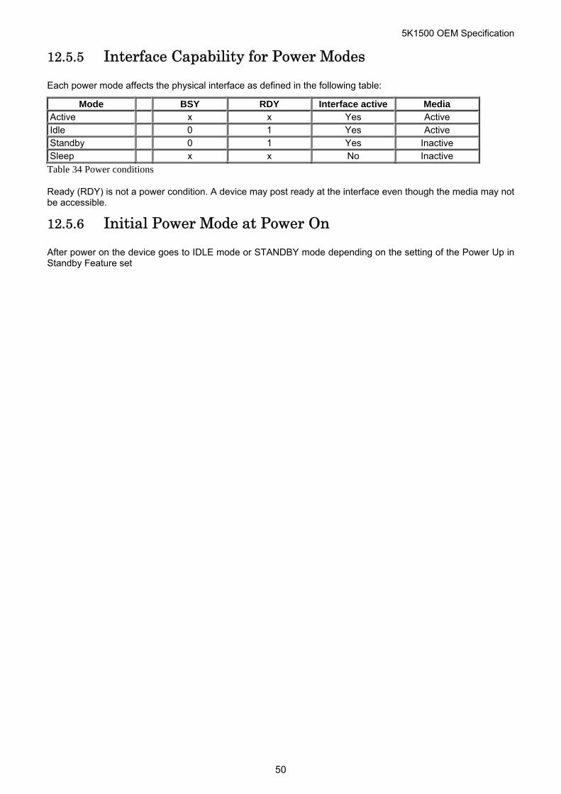
5K1500 OEM Specification
12.5.5 Interface Capability for Power Modes
Each power mode affects the physical interface as defined in the following table:
Mode BSY RDY Interface active Media Active x x Yes Active Idle 0 1 Yes Active Standby 0 1 Yes Inactive Sleep x x No Inactive
Table 34 Power conditions
Ready (RDY) is not a power condition. A device may post ready at the interface even though the media may not be accessible.
12.5.6 Initial Power Mode at Power On
After power on the device goes to IDLE mode or STANDBY mode depending on the setting of the Power Up in Standby Feature set
50
5K1500 OEM Specification
12.6 Advanced Power Management (Adaptive Battery Life Extender 3) Feature
This feature provides power saving without performance degradation. The Adaptive Battery Life Extender 3 (ABLE-3) technology intelligently manages transition among power modes within the device by monitoring access patterns of the host.
This technology has three idle modes; Performance Idle mode, Active Idle mode, and Low Power Idle mode.
This feature allows the host to select an advanced power management level. The advanced power management level is a scale from the lowest power consumption setting of 01h to the maximum performance level of Feh. Device performance may increase with increasing advanced power management levels. Device power consumption may increase with increasing advanced power management levels. The advanced power management levels contain discrete bands, described in the section of Set Feature command in detail.
This feature set uses the following functions:
A SET FEATURES subcommand to enable Advanced Power Management A SET FEATURES subcommand to disable Advanced Power Management
The Advanced Power Management feature is independent of the Standby timer setting. If both Advanced Power Management level and the Standby timer are set, the device will go to the Standby state when the timer times out or the device’s Advanced Power Management algorithm indicates that it is time to enter the Standby state.
The IDENTIFY DEVICE response word 83, bit 3 indicates that Advanced Power Management feature is supported if set. Word 86, bit 3 indicates that Advanced Power Management is enabled if set.
Word 91, bits 7-0 contain the current Advanced Power Management level if Advanced Power Management is enabled.
12.6.1 Performance Idle mode
This mode is usually entered immediately after Active mode command processing is complete, instead of conventional idle mode. In Performance Idle mode, all electronic components remain powered and full frequency servo remains operational. This provides instantaneous response to the next command. The duration of this mode is intelligently managed as described below.
12.6.2 Active Idle mode
In this mode, power consumption is 45-55% less than that of Performance Idle mode. Additional electronics are powered off, and the head is parked near the mid-diameter of the disk without servoing. Recovery time to Active mode is about 20ms.
12.6.3 Low Power Idle mode
Power consumption is 60%-65% less than that of Performance Idle mode. The heads are unloaded on the ramp, however the spindle is still rotated at the full speed. Recovery time to Active mode is about 300ms.
12.6.4 Transition Time
The transition time is dynamically managed by users recent access pattern, instead of fixed times. The ABLE-3 algorithm monitors the interval between commands instead of the command frequency of ABLE-2. The algorithm supposes that next command will come with the same command interval distribution as the previous access pattern. The algorithm calculates the expected average saving energy and response delay for next command in several transition time case based on this assumption. And it selects the most effective transition time with the condition that the calculated response delay is shorter than the value calculated from the specified level by Set Feature Enable Advanced Power Management command.
The optimal time to enter Active Idle mode is variable depending on the users recent behavior. It is not possible to achieve the same level of Power savings with a fixed entry time into Active Idle because every users data and access pattern is different. The optimum entry time changes over time.
The same algorithm works for entering into Low Power Idle mode and Standby mode, which consumes less power but need more recovery time switching from this mode to Active mode.
51
5K1500 OEM Specification
12.7 Interface Power Management Mode (Slumber and Partial)
Interface Power Management Mode is supported by both Device-initiated interface power management and Host-initiated interface power management. Please refer to the Serial ATA Specification about Power Management Mode.
52
5K1500 OEM Specification
12.8 S.M.A.R.T. Function The intent of Self-monitoring, analysis and reporting technology (S.M.A.R.T) is to protect user data and prevent unscheduled system downtime that may be caused by predictable degradation and/or fault of the device. By monitoring and storing critical performance and calibration parameters, S.M.A.R.T devices employ sophisticated data analysis algorithms to predict the likelihood of near-term degradation or fault condition. By alerting the host system of a negative reliability status condition, the host system can warn the user of the impending risk of a data loss and advise the user of appropriate action.
Since S.M.A.R.T. utilizes the internal device microprocessor and other device resources, there may be some small overhead associated with its operation. However, special care has been taken in the design of the S.M.A.R.T. algorithms to minimize the impact to host system performance. Actual impact of S.M.A.R.T. overhead is dependent on the specific device design and the usage patterns of the host system. To further ensure minimal impact to the user, S.M.A.R.T. capable devices are shipped from the device manufacturer’s factory with the S.M.A.R.T. feature disabled. S.M.A.R.T. capable devices can be enabled by the system OEMs at time of system integration or in the field by aftermarket products.
12.8.1 Attributes
Attributes are the specific performance or calibration parameters that are used in analyzing the status of the device. Attributes are selected by the device manufacturer based on that attribute’s ability to contribute to the prediction of degrading or faulty conditions for that particular device. The specific set of attributes being used and the identity of these attributes is vendor specific and proprietary.
12.8.2 Attribute values
Attribute values are used to represent the relative reliability of individual performance or calibration attributes. Higher attribute values indicate that the analysis algorithms being used by the device are predicting a lower probability of a degrading or fault condition existing. Accordingly, lower attribute values indicate that the analysis algorithms being used by the device are predicting a higher probability of a degrading or fault condition existing. There is no implied linear reliability relationship corresponding to the numerical relationship between different attribute values for any particular attribute.
12.8.3 Attribute thresholds
Each attribute value has a corresponding attribute threshold limit which is used for direct comparison to the attribute value to indicate the existence of a degrading or faulty condition. The numerical value of the attribute thresholds are determined by the device manufacturer through design and reliability testing and analysis. Each attribute threshold represents the lowest limit to which its corresponding attribute value can be equal while still retaining a positive reliability status. Attribute thresholds are set at the device manufacturer’s factory and cannot be changed in the field. The valid range for attribute thresholds is from 1 through 253 decimal.
12.8.4 Threshold exceeded condition
If one or more attribute values are less than or equal to their corresponding attribute thresholds, then the device reliability status is negative, indicating an impending degrading or faulty condition.
12.8.5 S.M.A.R.T. commands
The S.M.A.R.T. commands provide access to attribute values, attribute thresholds and other logging and reporting information.
12.8.6 S.M.A.R.T operation with power management modes
The device saves attribute values automatically on every head unload timing except the emergency unload, even if the attribute auto save feature is not enabled. The head unload is done not only by Standby, Standby Immediate, or Sleep command, but also by the automatic power saving functions like ABLE-3 or Standby timer. So basically it is not necessary for a host system to enable the attribute auto save feature, when it utilizes the power management. If the attribute auto save feature is enabled, attribute values will be saved after 30minutes passed since the last saving, besides above condition.
53
5K1500 OEM Specification
12.9 Security Mode Feature Set Security Mode Feature Set is a powerful security feature. With a device lock password, a user can prevent unauthorized access to hard disk device even if the device is removed from the computer.
New commands are supported for this feature as below.
Security Set Password (‘F1’h) Security Unlock (‘F2’h) Security Erase Prepare (‘F3’h) Security Erase Unit (‘F4’h) Security Freeze Lock (‘F5’h) Security Disable Password (‘F6’h)
12.9.1 Security mode
Following security modes are provided.
Device Locked mode The device disables media access commands after power on. Media access commands are enabled by either a security unlock command or a security erase unit command.
Device Unlocked mode The device enables all commands. If a password is not set this mode is entered after power on, otherwise it is entered by a security unlock or a security erase unit command.
Device Frozen mode The device enables all commands except those which can update the device lock function, set/change password. The device enters this mode via a Security Freeze Lock command. It cannot quit this mode until power off.
12.9.2 Security Level
Following security levels are provided.
High level security When the device lock function is enabled and the User Password is forgotten the device can be unlocked via a Master Password.
Maximum level security When the device lock function is enabled and the User Password is forgotten then only the Master Password with a Security Erase Unit command can unlock the device. Then user data is erased.
54
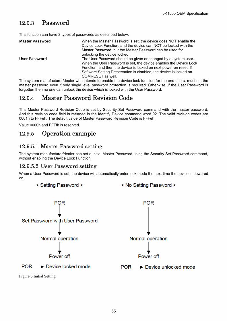
5K1500 OEM Specification
12.9.3 Password
This function can have 2 types of passwords as described below.
Master Password When the Master Password is set, the device does NOT enable the Device Lock Function, and the device can NOT be locked with the Master Password, but the Master Password can be used for unlocking the device locked.
User Password The User Password should be given or changed by a system user. When the User Password is set, the device enables the Device Lock Function, and then the device is locked on next power on reset. If Software Setting Preservation is disabled, the device is locked on COMRESET as well.
The system manufacturer/dealer who intends to enable the device lock function for the end users, must set the master password even if only single level password protection is required. Otherwise, if the User Password is forgotten then no one can unlock the device which is locked with the User Password.
12.9.4 Master Password Revision Code
This Master Password Revision Code is set by Security Set Password command with the master password. And this revision code field is returned in the Identify Device command word 92. The valid revision codes are 0001h to FFFeh. The default value of Master Password Revision Code is FFFeh.
Value 0000h and FFFfh is reserved.
12.9.5 Operation example
12.9.5.1 Master Password setting The system manufacturer/dealer can set a initial Master Password using the Security Set Password command, without enabling the Device Lock Function.
12.9.5.2 User Password setting When a User Password is set, the device will automatically enter lock mode the next time the device is powered on.
Figure 5 Initial Setting
55
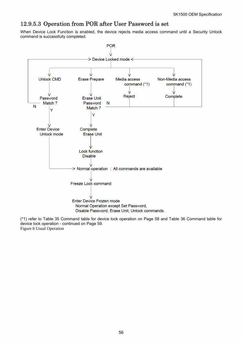
5K1500 OEM Specification
12.9.5.3 Operation from POR after User Password is set When Device Lock Function is enabled, the device rejects media access command until a Security Unlock command is successfully completed.
(*1) refer to Table 35 Command table for device lock operation on Page 58 and Table 36 Command table for device lock operation - continued on Page 59. Figure 6 Usual Operation
56
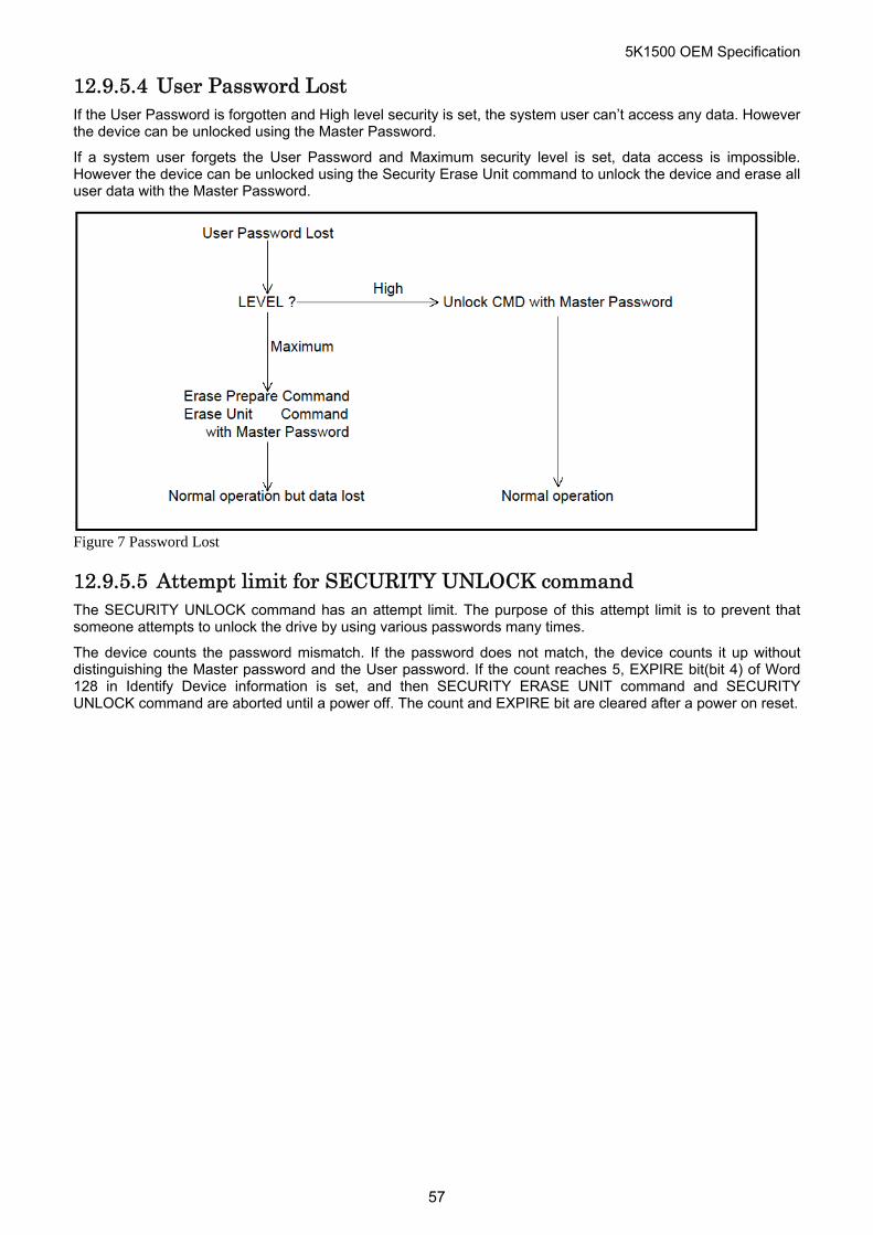
5K1500 OEM Specification
12.9.5.4 User Password Lost If the User Password is forgotten and High level security is set, the system user can’t access any data. However the device can be unlocked using the Master Password.
If a system user forgets the User Password and Maximum security level is set, data access is impossible. However the device can be unlocked using the Security Erase Unit command to unlock the device and erase all user data with the Master Password.
Figure 7 Password Lost
12.9.5.5 Attempt limit for SECURITY UNLOCK command The SECURITY UNLOCK command has an attempt limit. The purpose of this attempt limit is to prevent that someone attempts to unlock the drive by using various passwords many times.
The device counts the password mismatch. If the password does not match, the device counts it up without distinguishing the Master password and the User password. If the count reaches 5, EXPIRE bit(bit 4) of Word 128 in Identify Device information is set, and then SECURITY ERASE UNIT command and SECURITY UNLOCK command are aborted until a power off. The count and EXPIRE bit are cleared after a power on reset.
57
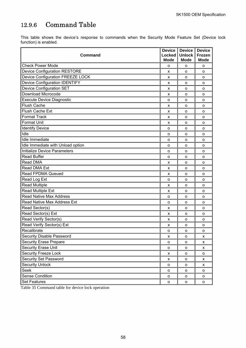
5K1500 OEM Specification
12.9.6 Command Table
This table shows the device’s response to commands when the Security Mode Feature Set (Device lock function) is enabled.
Command Device Locked Mode
Device Unlock Mode
Device FrozenMode
Check Power Mode o o o Device Configuration RESTORE x o o Device Configuration FREEZE LOCK x o o Device Configuration IDENTIFY x o o Device Configuration SET x o o Download Microcode x o o Execute Device Diagnostic o o o Flush Cache x o o Flush Cache Ext x o o Format Track x o o Format Unit x o o Identify Device o o o Idle o o o Idle Immediate o o o Idle Immediate with Unload option o o o Initialize Device Parameters o o o Read Buffer o o o Read DMA x o o Read DMA Ext x o o Read FPDMA Queued x o o Read Log Ext o o o Read Multiple x o o Read Multiple Ext x o o Read Native Max Address o o o Read Native Max Address Ext o o o Read Sector(s) x o o Read Sector(s) Ext x o o Read Verify Sector(s) x o o Read Verify Sector(s) Ext x o o Recalibrate o o o Security Disable Password x o x Security Erase Prepare o o x Security Erase Unit o o x Security Freeze Lock x o o Security Set Password x o x Security Unlock o o x Seek o o o Sense Condition o o o Set Features o o o
Table 35 Command table for device lock operation
58
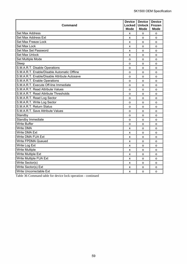
5K1500 OEM Specification
Command Device Locked Mode
Device Unlock Mode
Device FrozenMode
Set Max Address x o o Set Max Address Ext x o o Set Max Freeze Lock x o o Set Max Lock x o o Set Max Set Password x o o Set Max Unlock x o o Set Multiple Mode o o o Sleep o o o S.M.A.R.T. Disable Operations o o o S.M.A.R.T. Enable/Disable Automatic Offline o o o S.M.A.R.T. Enable/Disable Attribute Autosave o o o S.M.A.R.T. Enable Operations o o o S.M.A.R.T. Execute Off-line Immediate o o o S.M.A.R.T. Read Attribute Values o o o S.M.A.R.T. Read Attribute Thresholds o o o S.M.A.R.T. Read Log Sector o o o S.M.A.R.T. Write Log Sector o o o S.M.A.R.T. Return Status o o o S.M.A.R.T. Save Attribute Values o o o Standby o o o Standby Immediate o o o Write Buffer o o o Write DMA x o o Write DMA Ext x o o Write DMA FUA Ext x o o Write FPDMA Queued x o o Write Log Ext x o o Write Multiple x o o Write Multiple Ext x o o Write Multiple FUA Ext x o o Write Sector(s) x o o Write Sector(s) Ext x o o Write Uncorrectable Ext x o o
Table 36 Command table for device lock operation - continued
59
5K1500 OEM Specification
12.10 Protected Area Function Protected Area Function is to provide the ‘protected area’ which can not be accessed via conventional method. This ‘protected area’ is used to contain critical system data such as BIOS or system management information. The contents of entire system main memory may also be dumped into ‘protected area’ to resume after system power off.
The LBA/CYL changed by following command affects the Identify Device Information.
Two commands are defined for this function.
Read Native Max Address (‘F8’h) Set Max Address (‘F9’h)
Four security extension commands are implemented as sub-functions of the Set Max Address.
Set Max Set Password Set Max Lock Set Max Freeze Lock Set Max Unlock
12.10.1 Example for operation (In LBA mode)
Assumptions :
For better understanding, the following example uses actual values for LBA, size, etc. Since it is just an example, these values could be different.
Device characteristics
Capacity (native) : 536,870,912 byte (536MB) Max LBA (native) : 1,048,575 (0FFFFfh) Required size for protected area : 8,388,608 byte Required blocks for protected area : 16,384 (004000h) Customer usable device size : 528,482,304 byte (528MB) Customer usable sector count : 1,032,192 (0FC000h) LBA range for protected area : 0FC000h to 0FFFFfh
Shipping HDDs from HDD manufacturer
When the HDDs are shipped from HDD manufacturer, the device has been tested to have a capacity of 536MB,flagging the media defects not to be visible by system.
1. Preparing HDDs at system manufacturer
Special utility software is required to define the size of protected area and store the data into it.
The sequence is :
Issue Read Native Max Address command to get the real device max of LBA/CYL. Returned value shows that native device Max LBA is 0FFFFfh regardless to the current setting.
Make entire device be accessible including the protected area by setting device Max LBA as 0FFFFfh via Set Max Address command. The option could be either nonvolatile or volatile.
Test the sectors for protected area (LBA >= 0FC000h) if required.
Write information data such as BIOS code within the protected area.
Change maximum LBA using Set Max Address command to 0FBFFfh with nonvolatile option.
From this point, the protected area cannot be accessed until next Set Max Address command is issued. Any BIOSes, device drivers, or application software access the HDD as if that is the 528MB device because the device acts exactly same as real 528MB device does.
2. Conventional usage without system software support Since the HDD works as 528MB device, there is no special care to use this device for normal use.
60
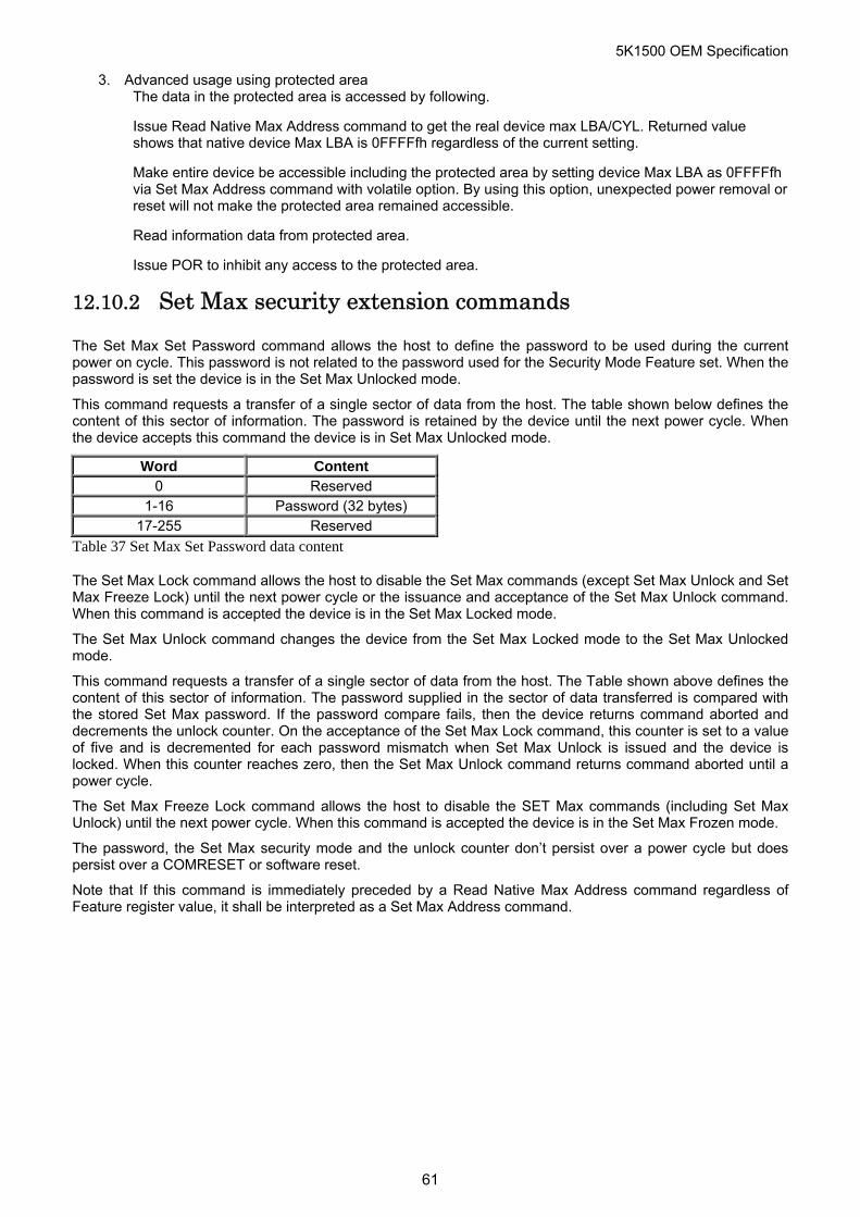
5K1500 OEM Specification
3. Advanced usage using protected area The data in the protected area is accessed by following.
Issue Read Native Max Address command to get the real device max LBA/CYL. Returned value shows that native device Max LBA is 0FFFFfh regardless of the current setting.
Make entire device be accessible including the protected area by setting device Max LBA as 0FFFFfh via Set Max Address command with volatile option. By using this option, unexpected power removal or reset will not make the protected area remained accessible.
Read information data from protected area.
Issue POR to inhibit any access to the protected area.
12.10.2 Set Max security extension commands
The Set Max Set Password command allows the host to define the password to be used during the current power on cycle. This password is not related to the password used for the Security Mode Feature set. When the password is set the device is in the Set Max Unlocked mode.
This command requests a transfer of a single sector of data from the host. The table shown below defines the content of this sector of information. The password is retained by the device until the next power cycle. When the device accepts this command the device is in Set Max Unlocked mode.
Word Content 0 Reserved
1-16 Password (32 bytes) 17-255 Reserved
Table 37 Set Max Set Password data content
The Set Max Lock command allows the host to disable the Set Max commands (except Set Max Unlock and Set Max Freeze Lock) until the next power cycle or the issuance and acceptance of the Set Max Unlock command. When this command is accepted the device is in the Set Max Locked mode.
The Set Max Unlock command changes the device from the Set Max Locked mode to the Set Max Unlocked mode.
This command requests a transfer of a single sector of data from the host. The Table shown above defines the content of this sector of information. The password supplied in the sector of data transferred is compared with the stored Set Max password. If the password compare fails, then the device returns command aborted and decrements the unlock counter. On the acceptance of the Set Max Lock command, this counter is set to a value of five and is decremented for each password mismatch when Set Max Unlock is issued and the device is locked. When this counter reaches zero, then the Set Max Unlock command returns command aborted until a power cycle.
The Set Max Freeze Lock command allows the host to disable the SET Max commands (including Set Max Unlock) until the next power cycle. When this command is accepted the device is in the Set Max Frozen mode.
The password, the Set Max security mode and the unlock counter don’t persist over a power cycle but does persist over a COMRESET or software reset.
Note that If this command is immediately preceded by a Read Native Max Address command regardless of Feature register value, it shall be interpreted as a Set Max Address command.
61
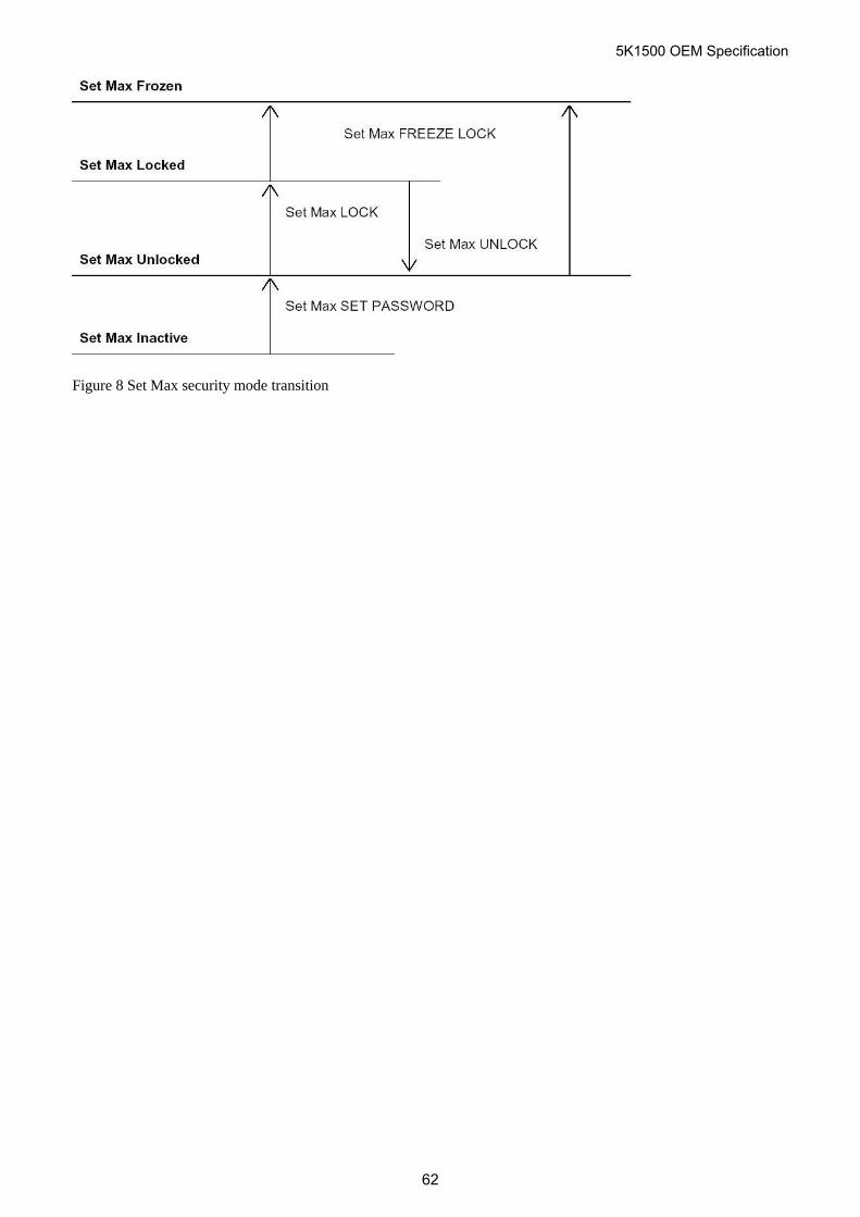
5K1500 OEM Specification
Figure 8 Set Max security mode transition
62
5K1500 OEM Specification
12.11 Write Cache Function Write cache is a performance enhancement whereby the device reports completion of the write command (Write Sector(s) and Write Multiple) to the host as soon as the device has received all of the data into its buffer. The device assumes responsibility to write the data subsequently onto the disk.
While writing data after completed acknowledgment of a write command, soft reset or COMRESET does not affect its operation. But power off terminates writing operation immediately and unwritten data are to be lost.
Flush cache, Soft reset, Standby, Standby Immediate and Sleep are executed after the completion of writing to disk media on enabling write cache function. So the host system can confirm the completion of write cache operation by issuing flush cache command, Soft reset, Standby command, Standby Immediate command or Sleep command, and then, by confirming its completion.
12.12 Reassign Function The reassign function is used with read commands and write commands. The sectors of data for reassignment are prepared as the spare data sector. The one entry can register up to 256 (512 byte/sector format) or 32 (4KB sector format) consecutive physical sectors maximally.
This reassignment information is registered internally, and the information is available right after completing the reassign function. Also the information is used on the next power on reset.
If the number of the spare sector reaches 0 sector, the reassign function will be disabled automatically.
The spare tracks for reassignment are located at regular intervals from Cylinder 0. As a result of reassignment, the physical location of logically sequenced sectors will be dispersed.
12.12.1 Auto Reassign Function
The sectors that show some errors may be reallocated automatically when specific conditions are met. The spare tracks for reallocation are located at regular intervals from Cylinder 0. The conditions for auto-reallocation are described below.
Non recovered write errors When a write operation can not be completed after the Error Recovery Procedure(ERP) is fully carried out, the sector(s) are reallocated to the spare location. An error is reported to the host system only when the write cache is disabled and the auto reallocation fails.
If the number of available spare sectors reaches 16 sectors, the write cache function will be disabled automatically.
Non recovered read errors When a read operation fails after defined ERP is fully carried out, a hard error is reported to the host system. This location is registered internally as a candidate for the reallocation. When a registered location is specified as a target of a write operation, a sequence of media verification is performed automatically. When the result of this verification meets the criteria, this sector is reallocated.
Recovered read errors When a read operation for a sector failed once then recovered at the specific ERP step, this sector of data is reallocated automatically. A media verification sequence may be run prior to the relocation according to the pre-defined conditions.
63
5K1500 OEM Specification
12.13 48-bit Address Feature Set The 48-bit Address feature set allows devices with capacities up to 281,474,976,710,655 sectors. This allows device capacity up to 144,115,188,075,855,360 bytes. In addition, the number of sectors that may be transferred by a single command are increased by increasing the allowable sector count to 16 bits.
Commands unique to the 48-bit Address feature set are:
Flush Cache Ext Read DMA Ext Read Multiple Ext Read Native Max Address Ext Read Sector(s) Ext Read Verify Sector(s) Ext Set Max Address Ext Write DMA Ext Write Multiple Ext Write Sector(s) Ext
The 48-bit Address feature set operates in LBA addressing only. Devices also implement commands using 28-bit addressing, and 28-bit and 48-bit commands may be intermixed.
Support of the 48-bit Address feature set is indicated in the Identify Device response bit 10 word 83. In addition, the maximum user LBA address accessible by 48-bit addressable commands is contained in Identify Device response words 100 through 103.
When the 48-bit Address feature set is implemented, the native maximum address is the value returned by a Read Native Max Address Ext command. If the native maximum address is equal to or less than 268,435,455, a Read Native Max Address shall return the native maximum address. If the native maximum address is greater than 268,435,455, a Read Native Max Address shall return a value of 268,435,455.
64
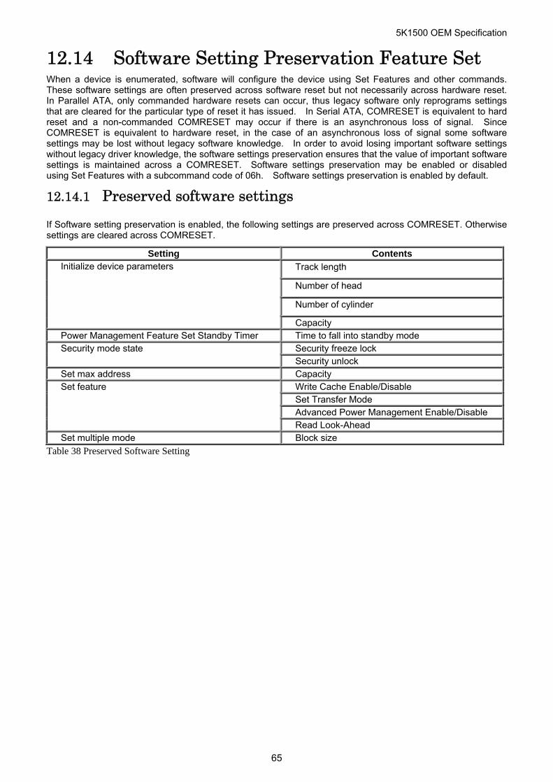
5K1500 OEM Specification
12.14 Software Setting Preservation Feature Set When a device is enumerated, software will configure the device using Set Features and other commands. These software settings are often preserved across software reset but not necessarily across hardware reset. In Parallel ATA, only commanded hardware resets can occur, thus legacy software only reprograms settings that are cleared for the particular type of reset it has issued. In Serial ATA, COMRESET is equivalent to hard reset and a non-commanded COMRESET may occur if there is an asynchronous loss of signal. Since COMRESET is equivalent to hardware reset, in the case of an asynchronous loss of signal some software settings may be lost without legacy software knowledge. In order to avoid losing important software settings without legacy driver knowledge, the software settings preservation ensures that the value of important software settings is maintained across a COMRESET. Software settings preservation may be enabled or disabled using Set Features with a subcommand code of 06h. Software settings preservation is enabled by default.
12.14.1 Preserved software settings
If Software setting preservation is enabled, the following settings are preserved across COMRESET. Otherwise settings are cleared across COMRESET.
Setting Contents
Track length
Number of head
Number of cylinder
Initialize device parameters
Capacity Power Management Feature Set Standby Timer Time to fall into standby mode
Security freeze lock Security mode state Security unlock
Set max address Capacity Write Cache Enable/Disable Set Transfer Mode Advanced Power Management Enable/Disable
Set feature
Read Look-Ahead Set multiple mode Block size
Table 38 Preserved Software Setting
65
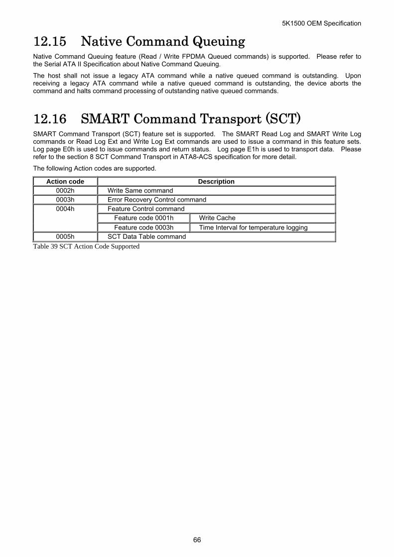
5K1500 OEM Specification
66
12.15 Native Command Queuing Native Command Queuing feature (Read / Write FPDMA Queued commands) is supported. Please refer to the Serial ATA II Specification about Native Command Queuing.
The host shall not issue a legacy ATA command while a native queued command is outstanding. Upon receiving a legacy ATA command while a native queued command is outstanding, the device aborts the command and halts command processing of outstanding native queued commands.
12.16 SMART Command Transport (SCT) SMART Command Transport (SCT) feature set is supported. The SMART Read Log and SMART Write Log commands or Read Log Ext and Write Log Ext commands are used to issue a command in this feature sets. Log page E0h is used to issue commands and return status. Log page E1h is used to transport data. Please refer to the section 8 SCT Command Transport in ATA8-ACS specification for more detail.
The following Action codes are supported.
Action code Description 0002h Write Same command 0003h Error Recovery Control command
Feature Control command Feature code 0001h Write Cache
0004h
Feature code 0003h Time Interval for temperature logging 0005h SCT Data Table command
Table 39 SCT Action Code Supported
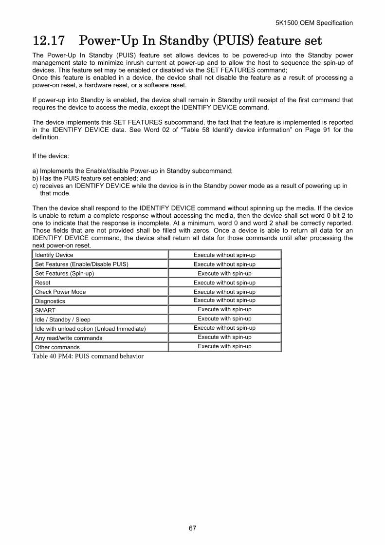
5K1500 OEM Specification
12.17 Power-Up In Standby (PUIS) feature set The Power-Up In Standby (PUIS) feature set allows devices to be powered-up into the Standby power management state to minimize inrush current at power-up and to allow the host to sequence the spin-up of devices. This feature set may be enabled or disabled via the SET FEATURES command; Once this feature is enabled in a device, the device shall not disable the feature as a result of processing a power-on reset, a hardware reset, or a software reset. If power-up into Standby is enabled, the device shall remain in Standby until receipt of the first command that requires the device to access the media, except the IDENTIFY DEVICE command. The device implements this SET FEATURES subcommand, the fact that the feature is implemented is reported in the IDENTIFY DEVICE data. See Word 02 of “Table 58 Identify device information” on Page 91 for the definition.
If the device: a) Implements the Enable/disable Power-up in Standby subcommand; b) Has the PUIS feature set enabled; and c) receives an IDENTIFY DEVICE while the device is in the Standby power mode as a result of powering up in
that mode. Then the device shall respond to the IDENTIFY DEVICE command without spinning up the media. If the device is unable to return a complete response without accessing the media, then the device shall set word 0 bit 2 to one to indicate that the response is incomplete. At a minimum, word 0 and word 2 shall be correctly reported. Those fields that are not provided shall be filled with zeros. Once a device is able to return all data for an IDENTIFY DEVICE command, the device shall return all data for those commands until after processing the next power-on reset.
Identify Device Execute without spin-up
Set Features (Enable/Disable PUIS) Execute without spin-up
Set Features (Spin-up) Execute with spin-up
Reset Execute without spin-up
Check Power Mode Execute without spin-up
Diagnostics Execute without spin-up
SMART Execute with spin-up
Idle / Standby / Sleep Execute with spin-up
Idle with unload option (Unload Immediate) Execute without spin-up
Any read/write commands Execute with spin-up
Other commands Execute with spin-up
Table 40 PM4: PUIS command behavior
67
5K1500 OEM Specification
12.18 Early Drive Ready (EDR) function The Early Drive Ready (EDR) function is implemented. In this function, power on reset (POR) process is divided in two processes; POR1 and POR2. POR1 is the process for provide drive read operation; POR2 is the process for drive write operation. When EDR function is implemented, the drive returns Ready (Status: Error = 50:01) when POR1 is completed. POR2 is started by any of following condition. - Write type commands received - 2 seconds passed after drive ready - 500 milliseconds command interval POR2 is interrupted only by free fall sensor (FFS) or unload immediate (ULI) command interrupt. Other commands received while POR2 is running processed after POR2 is completed. After POR2 is interrupted by FFS or ULI, POR2 will be executed after FFS/ULI is resumed. All ATA commands are divided in two groups; read type and write type. Two ‘ready’ states are defined for the EDR function supported drive; Read Ready and Full Ready. Drive enters ‘Read Ready’ state when POR1 is completed, and enters ‘Full Ready’ state when POR2 is completed. While ‘Read Ready’ state, drive accepts and executes read type commands. Write type commands are accepted but POR2 is carried out before executing the command. Command Read / Write types are defined as follows. Soft reset and hard reset are treated as read type command.
68
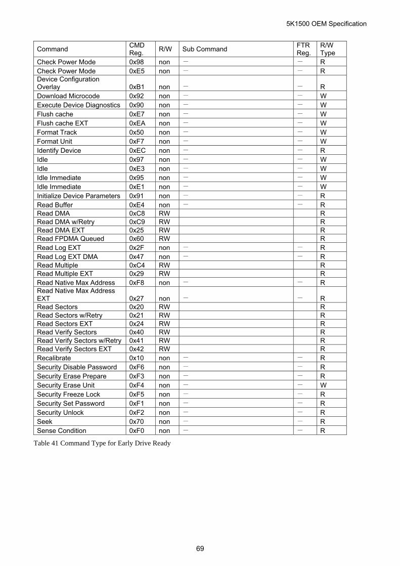
5K1500 OEM Specification
69
Command CMD Reg.
R/W Sub Command FTR Reg.
R/W Type
Check Power Mode 0x98 non - - R Check Power Mode 0xE5 non - - R Device Configuration Overlay 0xB1 non - - R Download Microcode 0x92 non - - W Execute Device Diagnostics 0x90 non - - W Flush cache 0xE7 non - - W Flush cache EXT 0xEA non - - W Format Track 0x50 non - - W Format Unit 0xF7 non - - W Identify Device 0xEC non - - R Idle 0x97 non - - W Idle 0xE3 non - - W Idle Immediate 0x95 non - - W Idle Immediate 0xE1 non - - W Initialize Device Parameters 0x91 non - - R Read Buffer 0xE4 non - - R Read DMA 0xC8 RW R Read DMA w/Retry 0xC9 RW R Read DMA EXT 0x25 RW R Read FPDMA Queued 0x60 RW R Read Log EXT 0x2F non - - R Read Log EXT DMA 0x47 non - - R Read Multiple 0xC4 RW R Read Multiple EXT 0x29 RW R Read Native Max Address 0xF8 non - - R Read Native Max Address EXT 0x27 non - - R Read Sectors 0x20 RW R Read Sectors w/Retry 0x21 RW R Read Sectors EXT 0x24 RW R Read Verify Sectors 0x40 RW R Read Verify Sectors w/Retry 0x41 RW R Read Verify Sectors EXT 0x42 RW R Recalibrate 0x10 non - - R Security Disable Password 0xF6 non - - R Security Erase Prepare 0xF3 non - - R Security Erase Unit 0xF4 non - - W Security Freeze Lock 0xF5 non - - R Security Set Password 0xF1 non - - R Security Unlock 0xF2 non - - R Seek 0x70 non - - R Sense Condition 0xF0 non - - R
Table 41 Command Type for Early Drive Ready
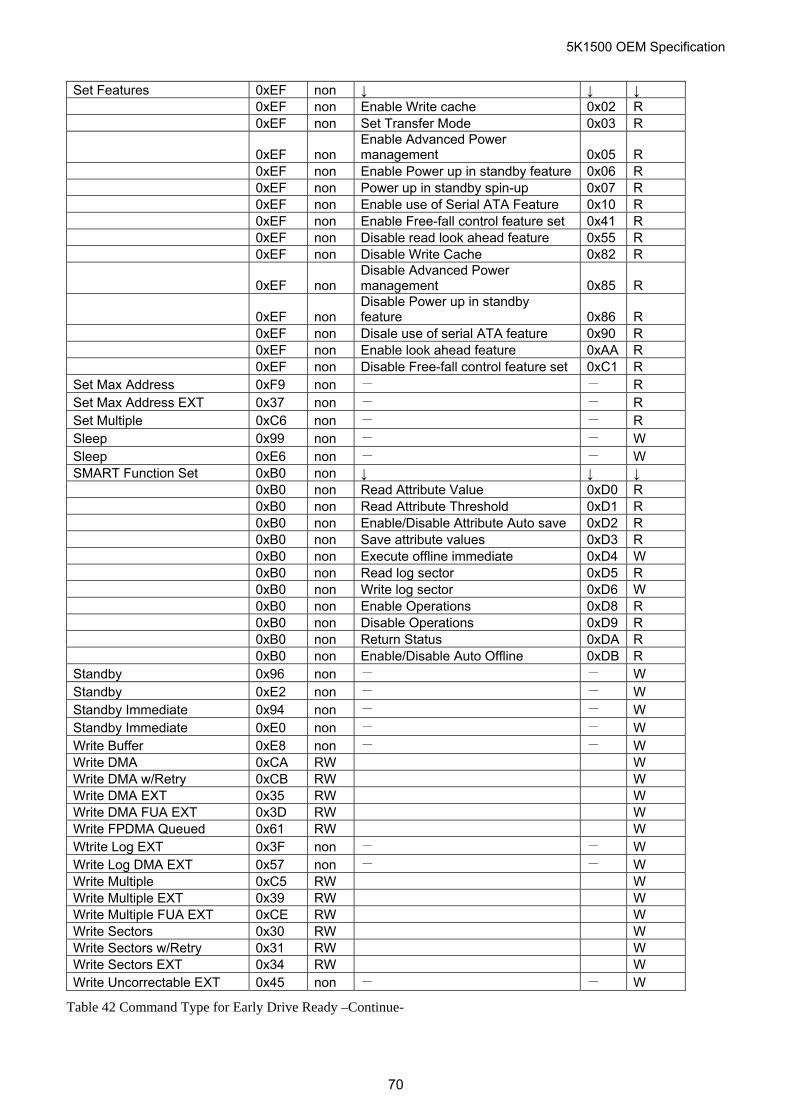
5K1500 OEM Specification
Set Features 0xEF non ↓ ↓ ↓ 0xEF non Enable Write cache 0x02 R 0xEF non Set Transfer Mode 0x03 R
0xEF non Enable Advanced Power management 0x05 R
0xEF non Enable Power up in standby feature 0x06 R 0xEF non Power up in standby spin-up 0x07 R 0xEF non Enable use of Serial ATA Feature 0x10 R 0xEF non Enable Free-fall control feature set 0x41 R 0xEF non Disable read look ahead feature 0x55 R 0xEF non Disable Write Cache 0x82 R
0xEF non Disable Advanced Power management 0x85 R
0xEF non Disable Power up in standby feature 0x86 R
0xEF non Disale use of serial ATA feature 0x90 R 0xEF non Enable look ahead feature 0xAA R 0xEF non Disable Free-fall control feature set 0xC1 R Set Max Address 0xF9 non - - R Set Max Address EXT 0x37 non - - R Set Multiple 0xC6 non - - R Sleep 0x99 non - - W Sleep 0xE6 non - - W SMART Function Set 0xB0 non ↓ ↓ ↓ 0xB0 non Read Attribute Value 0xD0 R 0xB0 non Read Attribute Threshold 0xD1 R 0xB0 non Enable/Disable Attribute Auto save 0xD2 R 0xB0 non Save attribute values 0xD3 R 0xB0 non Execute offline immediate 0xD4 W 0xB0 non Read log sector 0xD5 R 0xB0 non Write log sector 0xD6 W 0xB0 non Enable Operations 0xD8 R 0xB0 non Disable Operations 0xD9 R 0xB0 non Return Status 0xDA R 0xB0 non Enable/Disable Auto Offline 0xDB R Standby 0x96 non - - W Standby 0xE2 non - - W Standby Immediate 0x94 non - - W Standby Immediate 0xE0 non - - W Write Buffer 0xE8 non - - W Write DMA 0xCA RW W Write DMA w/Retry 0xCB RW W Write DMA EXT 0x35 RW W Write DMA FUA EXT 0x3D RW W Write FPDMA Queued 0x61 RW W Wtrite Log EXT 0x3F non - - W Write Log DMA EXT 0x57 non - - W Write Multiple 0xC5 RW W Write Multiple EXT 0x39 RW W Write Multiple FUA EXT 0xCE RW W Write Sectors 0x30 RW W Write Sectors w/Retry 0x31 RW W Write Sectors EXT 0x34 RW W Write Uncorrectable EXT 0x45 non - - W
Table 42 Command Type for Early Drive Ready –Continue-
70
5K1500 OEM Specification
13 Command Protocol The commands are grouped into different classes according to the protocols followed for command execution. The command classes with their associated protocols are defined below.
Please refer to Serial ATA Revision 3.0 (Section 11. device command layer protocol) about each protocol.
For all commands, the host must first check if BSY=1, and should proceed no further unless and until BSY=0. For all commands, the host must also wait for RDY=1 before proceeding.
A device must maintain either BSY=1 or DRQ=1 at all times until the command is completed. The INTRQ signal is used by the device to signal most, but not all, times when the BSY bit is changed from 1 to 0 during command execution.
A command shall only be interrupted with a COMRESET or software reset. The result of writing to the Command register while BSY=1 or DRQ=1 is unpredictable and may result in data corruption. A command should only be interrupted by a reset at times when the host thinks there may be a problem, such as a device that is no longer responding.
Interrupts are cleared when the host reads the Status Register, issues a reset, or writes to the Command Register.
“Table 144 Timeout Values” on Page 175 shows the device timeout values.
13.1 Data In Commands These commands are:
Device Configuration Identify Identify Device Read Buffer Read Log Ext Read Multiple Read Multiple Ext Read Sector(s) Read Sector(s) Ext S.M.A.R.T. Read Attribute Values S.M.A.R.T. Read Attribute Thresholds S.M.A.R.T. Read log sector
Execution includes the transfer of one or more 512 byte (>512 bytes on Read Long) sectors of data from the device to the host.
Note that the status data for a sector of data is available in the Status Register before the sector is transferred to the host.
If the device detects an invalid parameter, then it will abort the command by setting BSY=0, ERR=1, ABT=1.
If an error occurs, the device will set BSY=0, ERR=1, and DRQ=1. The device will then store the error status in the Error Register. The registers will contain the location of the sector in error. The erroneous location will be reported with CHS mode or LBA mode, the mode is decided by mode select bit (bit 6) of Device register on issuing the command.
13.2 Data Out Commands These commands are:
Device Configuration Set Download Microcode Format Track Security Disable Password Security Erase Unit Security Set Password Security Unlock Set Max Set Password Set Max Unlock S.M.A.R.T Write Log Sector
71
5K1500 OEM Specification
Write Buffer Write Log Ext Write Multiple Write Multiple Ext Write Multiple FUA Ext Write Sector(s) Write Sector(s) Ext
Execution includes the transfer of one or more 512 byte (>512 bytes on Write Long) sectors of data from the host to the device.
If the device detects an invalid parameter, then it will abort the command by setting BSY=0, ERR=1, ABT=1.
If an uncorrectable error occurs, the device will set BSY=0 and ERR=1, store the error status in the Error Register. The registers will contain the location of the sector in error. The errored location will be reported with CHS mode or LBA mode. The mode is decided by mode select bit (bit 6) of Device register on issuing the command.
13.3 Non-Data Commands These commands are:
Check Power Mode Device Configuration Freeze Lock Device Configuration Restore Execute Device Diagnostic Flush Cache Flush Cache Ext Format Unit Idle Idle Immediate Idle Immediate with Unload option Initialize Device Parameters Read Native Max Address Read Native Max Address Ext Read Verify Sector(s) Read Verify Sector(s) Ext Recalibrate Security Erase Prepare Security Freeze Lock Seek Sense Condition Set Features Set Max Address Set Max Address Ext Set Max Lock Set Max Freeze Lock Set Multiple Mode Sleep S.M.A.R.T. Disable Operations S.M.A.R.T. Enable/Disable Attribute Autosave S.M.A.R.T. Enable/Disable Automatic Off-line S.M.A.R.T. Enable Operations S.M.A.R.T. Execute Off-line Immediate S.M.A.R.T. Return Status S.M.A.R.T. Save Attribute Values Standby Standby Immediate Write Uncorrectable Ext
Execution of these commands involves no data transfer.
72
5K1500 OEM Specification
13.4 DMA Data Transfer Commands These commands are:
Read DMA Read DMA Ext Write DMA Write DMA Ext Write DMA FUA Ext
Initiation of the DMA transfer commands is identical to the Read Sector or Write Sector commands except that the host initializes the slave-DMA channel prior to issuing the command.
The DMA protocol allows high performance multi-tasking operating systems to eliminate processor overhead associated with PIO transfers.
Refer Functional Specification part for further details.
13.5 First-parity DMA Commands These commands are:
Read FPDMA Queued Write FPDMA Queued
Execution of this class of commands includes command queuing and the transfer of one or more blocks of data between the device and the host. The protocol is described in the section 11.14 “FPDMA Queued command protocol” of “Serial ATA revision 3.0”.
73
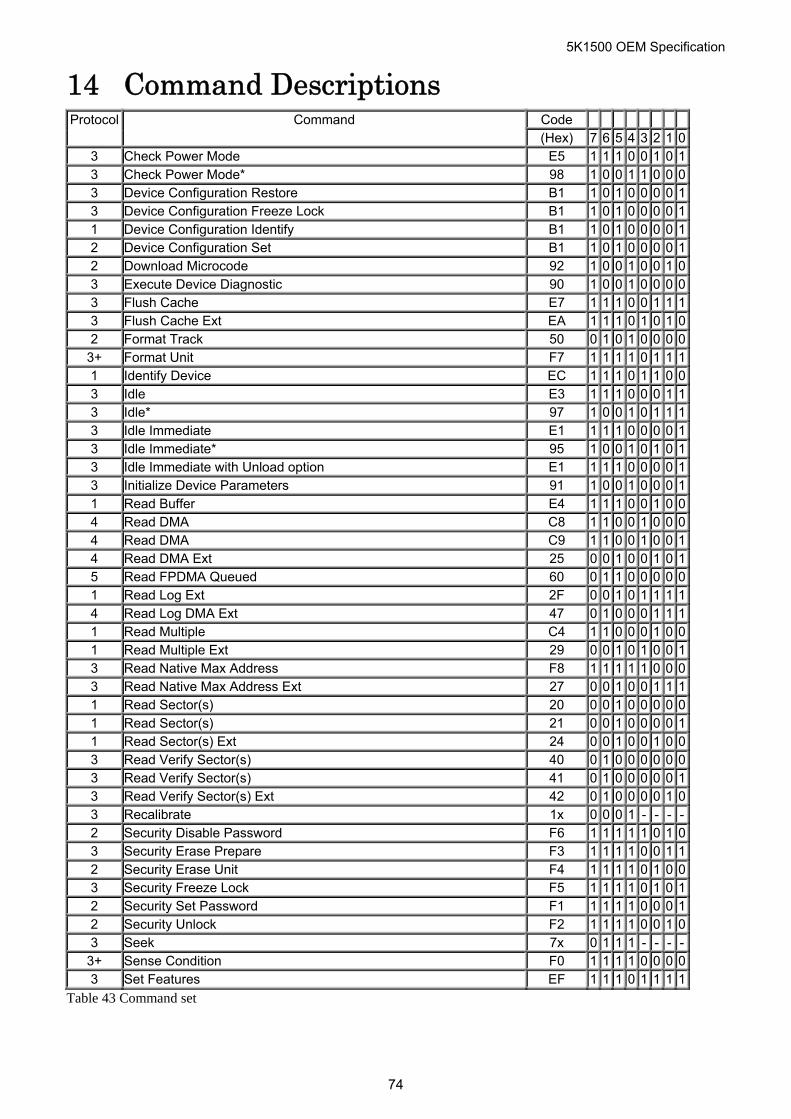
5K1500 OEM Specification
14 Command Descriptions Code Protocol Command (Hex) 7 6 5 4 3 2 1 0
3 Check Power Mode E5 1 1 1 0 0 1 0 13 Check Power Mode* 98 1 0 0 1 1 0 0 03 Device Configuration Restore B1 1 0 1 0 0 0 0 13 Device Configuration Freeze Lock B1 1 0 1 0 0 0 0 11 Device Configuration Identify B1 1 0 1 0 0 0 0 12 Device Configuration Set B1 1 0 1 0 0 0 0 12 Download Microcode 92 1 0 0 1 0 0 1 03 Execute Device Diagnostic 90 1 0 0 1 0 0 0 03 Flush Cache E7 1 1 1 0 0 1 1 13 Flush Cache Ext EA 1 1 1 0 1 0 1 02 Format Track 50 0 1 0 1 0 0 0 0
3+ Format Unit F7 1 1 1 1 0 1 1 11 Identify Device EC 1 1 1 0 1 1 0 03 Idle E3 1 1 1 0 0 0 1 13 Idle* 97 1 0 0 1 0 1 1 13 Idle Immediate E1 1 1 1 0 0 0 0 13 Idle Immediate* 95 1 0 0 1 0 1 0 13 Idle Immediate with Unload option E1 1 1 1 0 0 0 0 13 Initialize Device Parameters 91 1 0 0 1 0 0 0 11 Read Buffer E4 1 1 1 0 0 1 0 04 Read DMA C8 1 1 0 0 1 0 0 04 Read DMA C9 1 1 0 0 1 0 0 14 Read DMA Ext 25 0 0 1 0 0 1 0 15 Read FPDMA Queued 60 0 1 1 0 0 0 0 01 Read Log Ext 2F 0 0 1 0 1 1 1 14 Read Log DMA Ext 47 0 1 0 0 0 1 1 11 Read Multiple C4 1 1 0 0 0 1 0 01 Read Multiple Ext 29 0 0 1 0 1 0 0 13 Read Native Max Address F8 1 1 1 1 1 0 0 03 Read Native Max Address Ext 27 0 0 1 0 0 1 1 11 Read Sector(s) 20 0 0 1 0 0 0 0 01 Read Sector(s) 21 0 0 1 0 0 0 0 11 Read Sector(s) Ext 24 0 0 1 0 0 1 0 03 Read Verify Sector(s) 40 0 1 0 0 0 0 0 03 Read Verify Sector(s) 41 0 1 0 0 0 0 0 13 Read Verify Sector(s) Ext 42 0 1 0 0 0 0 1 03 Recalibrate 1x 0 0 0 1 - - - -2 Security Disable Password F6 1 1 1 1 1 0 1 03 Security Erase Prepare F3 1 1 1 1 0 0 1 12 Security Erase Unit F4 1 1 1 1 0 1 0 03 Security Freeze Lock F5 1 1 1 1 0 1 0 12 Security Set Password F1 1 1 1 1 0 0 0 12 Security Unlock F2 1 1 1 1 0 0 1 03 Seek 7x 0 1 1 1 - - - -
3+ Sense Condition F0 1 1 1 1 0 0 0 03 Set Features EF 1 1 1 0 1 1 1 1
Table 43 Command set
74
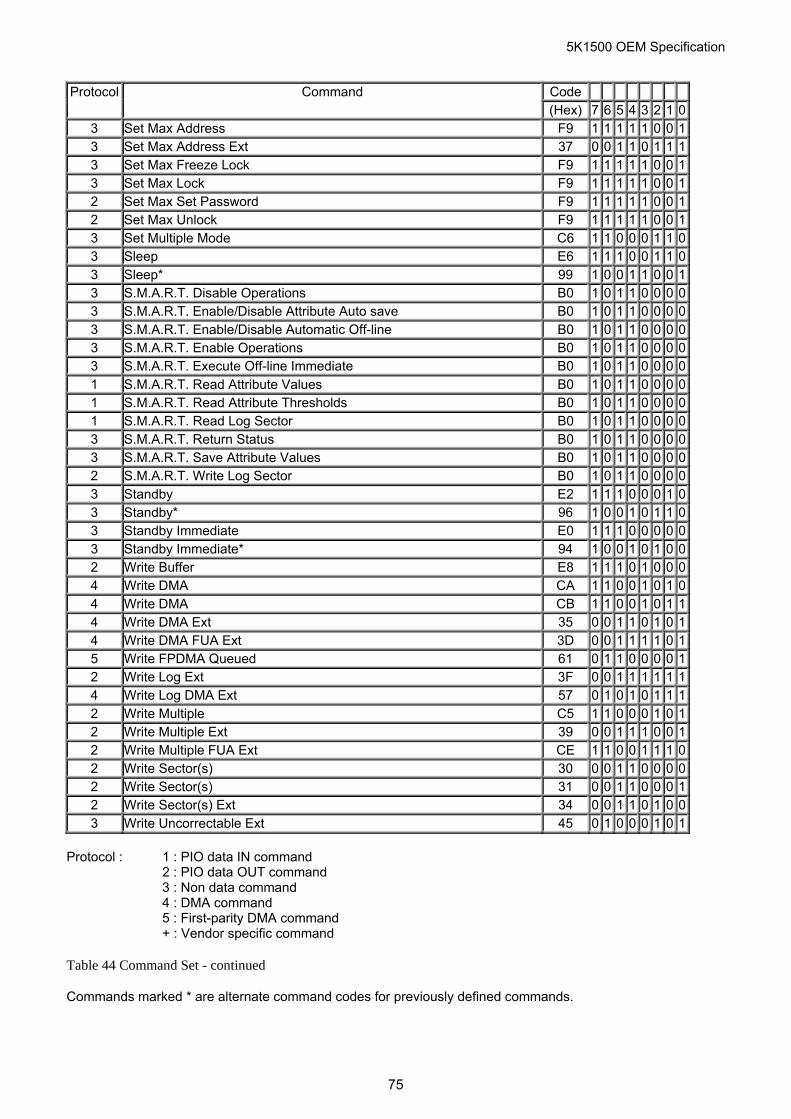
5K1500 OEM Specification
Code Protocol Command (Hex) 7 6 5 4 3 2 1 0
3 Set Max Address F9 1 1 1 1 1 0 0 13 Set Max Address Ext 37 0 0 1 1 0 1 1 13 Set Max Freeze Lock F9 1 1 1 1 1 0 0 13 Set Max Lock F9 1 1 1 1 1 0 0 12 Set Max Set Password F9 1 1 1 1 1 0 0 12 Set Max Unlock F9 1 1 1 1 1 0 0 13 Set Multiple Mode C6 1 1 0 0 0 1 1 03 Sleep E6 1 1 1 0 0 1 1 03 Sleep* 99 1 0 0 1 1 0 0 13 S.M.A.R.T. Disable Operations B0 1 0 1 1 0 0 0 03 S.M.A.R.T. Enable/Disable Attribute Auto save B0 1 0 1 1 0 0 0 03 S.M.A.R.T. Enable/Disable Automatic Off-line B0 1 0 1 1 0 0 0 03 S.M.A.R.T. Enable Operations B0 1 0 1 1 0 0 0 03 S.M.A.R.T. Execute Off-line Immediate B0 1 0 1 1 0 0 0 01 S.M.A.R.T. Read Attribute Values B0 1 0 1 1 0 0 0 01 S.M.A.R.T. Read Attribute Thresholds B0 1 0 1 1 0 0 0 01 S.M.A.R.T. Read Log Sector B0 1 0 1 1 0 0 0 03 S.M.A.R.T. Return Status B0 1 0 1 1 0 0 0 03 S.M.A.R.T. Save Attribute Values B0 1 0 1 1 0 0 0 02 S.M.A.R.T. Write Log Sector B0 1 0 1 1 0 0 0 03 Standby E2 1 1 1 0 0 0 1 03 Standby* 96 1 0 0 1 0 1 1 03 Standby Immediate E0 1 1 1 0 0 0 0 03 Standby Immediate* 94 1 0 0 1 0 1 0 02 Write Buffer E8 1 1 1 0 1 0 0 04 Write DMA CA 1 1 0 0 1 0 1 04 Write DMA CB 1 1 0 0 1 0 1 14 Write DMA Ext 35 0 0 1 1 0 1 0 14 Write DMA FUA Ext 3D 0 0 1 1 1 1 0 15 Write FPDMA Queued 61 0 1 1 0 0 0 0 12 Write Log Ext 3F 0 0 1 1 1 1 1 14 Write Log DMA Ext 57 0 1 0 1 0 1 1 12 Write Multiple C5 1 1 0 0 0 1 0 12 Write Multiple Ext 39 0 0 1 1 1 0 0 12 Write Multiple FUA Ext CE 1 1 0 0 1 1 1 02 Write Sector(s) 30 0 0 1 1 0 0 0 02 Write Sector(s) 31 0 0 1 1 0 0 0 12 Write Sector(s) Ext 34 0 0 1 1 0 1 0 03 Write Uncorrectable Ext 45 0 1 0 0 0 1 0 1
Protocol : 1 : PIO data IN command
2 : PIO data OUT command 3 : Non data command 4 : DMA command 5 : First-parity DMA command + : Vendor specific command
Table 44 Command Set - continued
Commands marked * are alternate command codes for previously defined commands.
75
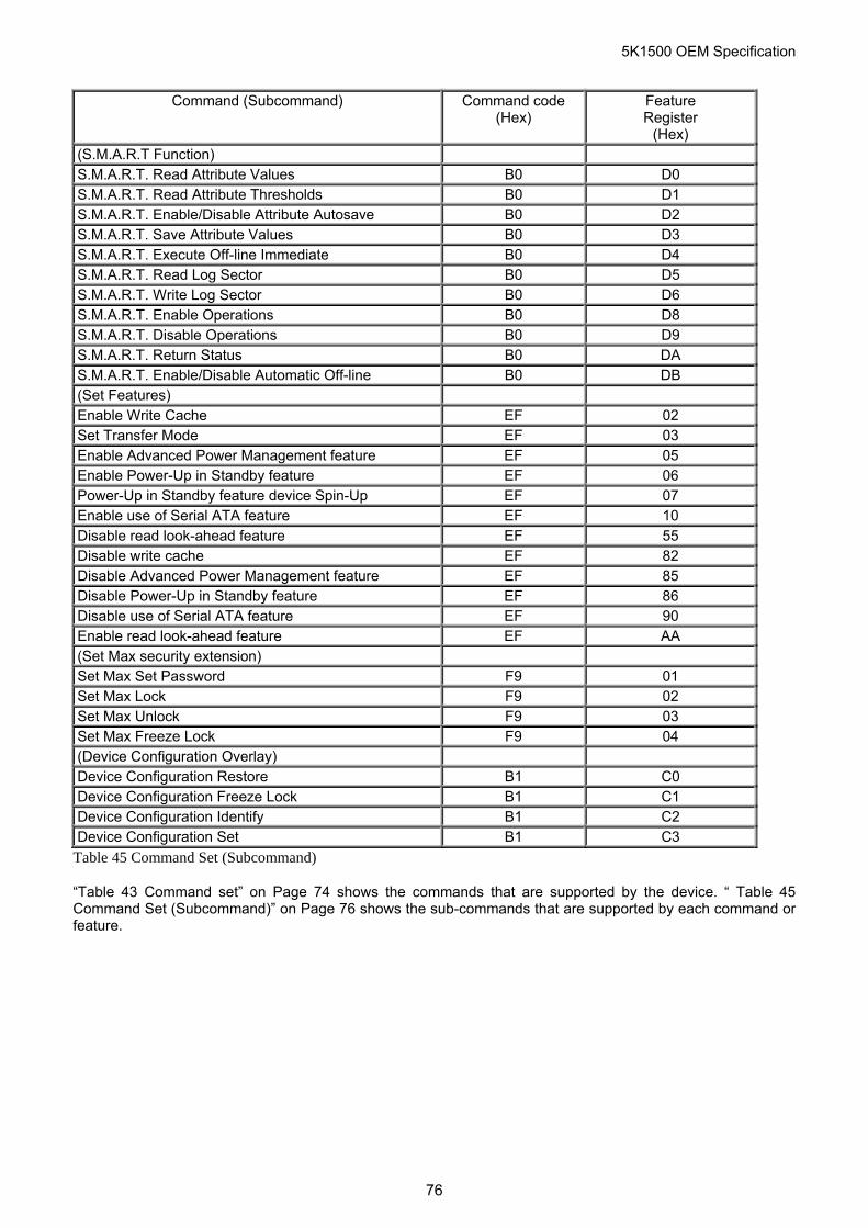
5K1500 OEM Specification
Command (Subcommand) Command code
(Hex) Feature Register
(Hex) (S.M.A.R.T Function) S.M.A.R.T. Read Attribute Values B0 D0 S.M.A.R.T. Read Attribute Thresholds B0 D1 S.M.A.R.T. Enable/Disable Attribute Autosave B0 D2 S.M.A.R.T. Save Attribute Values B0 D3 S.M.A.R.T. Execute Off-line Immediate B0 D4 S.M.A.R.T. Read Log Sector B0 D5 S.M.A.R.T. Write Log Sector B0 D6 S.M.A.R.T. Enable Operations B0 D8 S.M.A.R.T. Disable Operations B0 D9 S.M.A.R.T. Return Status B0 DA S.M.A.R.T. Enable/Disable Automatic Off-line B0 DB (Set Features) Enable Write Cache EF 02 Set Transfer Mode EF 03 Enable Advanced Power Management feature EF 05 Enable Power-Up in Standby feature EF 06 Power-Up in Standby feature device Spin-Up EF 07 Enable use of Serial ATA feature EF 10 Disable read look-ahead feature EF 55 Disable write cache EF 82 Disable Advanced Power Management feature EF 85 Disable Power-Up in Standby feature EF 86 Disable use of Serial ATA feature EF 90 Enable read look-ahead feature EF AA (Set Max security extension) Set Max Set Password F9 01 Set Max Lock F9 02 Set Max Unlock F9 03 Set Max Freeze Lock F9 04 (Device Configuration Overlay) Device Configuration Restore B1 C0 Device Configuration Freeze Lock B1 C1 Device Configuration Identify B1 C2 Device Configuration Set B1 C3
Table 45 Command Set (Subcommand)
“Table 43 Command set” on Page 74 shows the commands that are supported by the device. “ Table 45 Command Set (Subcommand)” on Page 76 shows the sub-commands that are supported by each command or feature.
76
5K1500 OEM Specification
The following symbols are used in the command descriptions:
Output Registers 0 Indicates that the bit must be set to 0. 1 Indicates that the bit must be set to 1. H Head number. Indicates that the head number part of the Device Register is an output parameter and
should be specified. L LBA mode. Indicates the addressing mode. Zero specifies CHS mode and one does LBA addressing
mode. R Retry. Original meaning is already obsolete, there is no difference between 0 and 1. (Using 0 is
recommended for future compatibility.) B Option Bit. Indicates that the Option Bit of the Sector Count Register should be specified. (This bit is
used by Set Max ADDRESS command) V Valid. Indicates that the bit is part of an output parameter and should be specified. X Indicates that the hex character is not used. - Indicates that the bit is not used. Input Registers 0 Indicates that the bit is always set to 0. 1 Indicates that the bit is always set to 1. H Head number. Indicates that the head number part of the Device Register is an input parameter and will
be set by the device. V Valid. Indicates that the bit is part of an input parameter and will be set to 0 or 1 by the device. N Not recommendable condition for start up. Indicates that the condition of device is not recommendable
for start up. - Indicates that the bit is not part of an input parameter. The command descriptions show the contents of the Status and Error Registers after the device has completed processing the command.
77
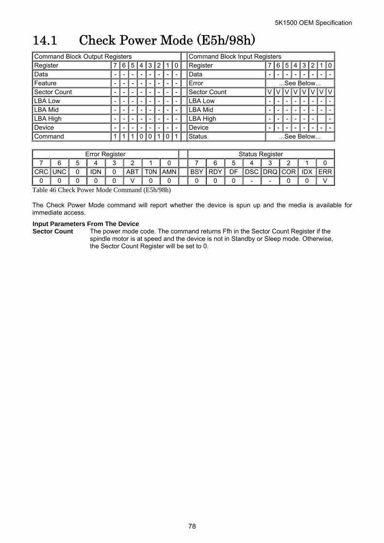
5K1500 OEM Specification
14.1 Check Power Mode (E5h/98h) Command Block Output Registers Command Block Input Registers Register 7 6 5 4 3 2 1 0 Register 7 6 5 4 3 2 1 0Data - - - - - - - - Data - - - - - - - -Feature - - - - - - - - Error ...See Below... Sector Count - - - - - - - - Sector Count V V V V V V V VLBA Low - - - - - - - - LBA Low - - - - - - - -LBA Mid - - - - - - - - LBA Mid - - - - - - - -LBA High - - - - - - - - LBA High - - - - - - -Device - - - - - - - - Device - - - - - - - -Command 1 1 1 0 0 1 0 1 Status ...See Below...
Error Register Status Register
7 6 5 4 3 2 1 0 7 6 5 4 3 2 1 0 CRC UNC 0 IDN 0 ABT T0N AMN BSY RDY DF DSC DRQ COR IDX ERR
0 0 0 0 0 V 0 0 0 0 0 - - 0 0 V
Table 46 Check Power Mode Command (E5h/98h)
The Check Power Mode command will report whether the device is spun up and the media is available for immediate access.
Input Parameters From The Device Sector Count The power mode code. The command returns Ffh in the Sector Count Register if the
spindle motor is at speed and the device is not in Standby or Sleep mode. Otherwise, the Sector Count Register will be set to 0.
78
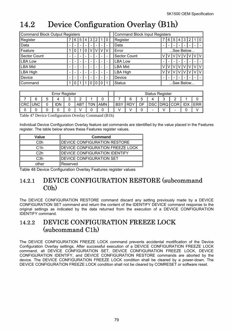
5K1500 OEM Specification
14.2 Device Configuration Overlay (B1h) Command Block Output Registers Command Block Input Registers Register 7 6 5 4 3 2 1 0 Register 7 6 5 4 3 2 1 0Data - - - - - - - - Data - - - - - - - -Feature 1 0 1 0 V V V V Error ...See Below... Sector Count - - - - - - - - Sector Count V V V V V V V VLBA Low - - - - - - - - LBA Low - - - - - - - -LBA Mid - - - - - - - - LBA Mid V V V V V V V VLBA High - - - - - - - - LBA High V V V V V V V VDevice - - - - - - - - Device - - - - - - - -Command 1 0 1 1 0 0 0 1 Status ...See Below...
Error Register Status Register
7 6 5 4 3 2 1 0 7 6 5 4 3 2 1 0 CRC UNC 0 IDN 0 ABT T0N AMN BSY RDY DF DSC DRQ COR IDX ERR
0 0 0 0 0 V 0 0 V V 0 - V - 0 V
Table 47 Device Configuration Overlay Command (B1h)
Individual Device Configuration Overlay feature set commands are identified by the value placed in the Features register. The table below shows these Features register values.
Value Command C0h DEVICE CONFIGURATION RESTORE C1h DEVICE CONFIGURATION FREEZE LOCK C2h DEVICE CONFIGURATION IDENTIFY C3h DEVICE CONFIGURATION SET other Reserved
Table 48 Device Configuration Overlay Features register values
14.2.1 DEVICE CONFIGURATION RESTORE (subcommand C0h)
The DEVICE CONFIGURATION RESTORE command discard any setting previously made by a DEVICE CONFIGURATION SET command and return the content of the IDENTIFY DEVICE command response to the original settings as indicated by the data returned from the execution of a DEVICE CONFIGURATION IDENTIFY command.
14.2.2 DEVICE CONFIGURATION FREEZE LOCK (subcommand C1h)
The DEVICE CONFIGURATION FREEZE LOCK command prevents accidental modification of the Device Configuration Overlay settings. After successful execution of a DEVICE CONFIGURATION FREEZE LOCK command, all DEVICE CONFIGURATION SET, DEVICE CONFIGURATION FREEZE LOCK, DEVICE CONFIGURATION IDENTIFY, and DEVICE CONFIGURATION RESTORE commands are aborted by the device. The DEVICE CONFIGURATION FREEZE LOCK condition shall be cleared by a power-down. The DEVICE CONFIGURATION FREEZE LOCK condition shall not be cleared by COMRESET or software reset.
79
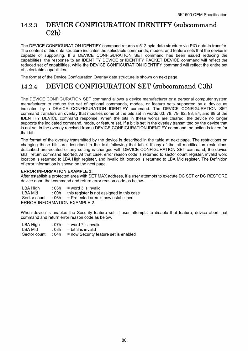
5K1500 OEM Specification
14.2.3 DEVICE CONFIGURATION IDENTIFY (subcommand C2h)
The DEVICE CONFIGURATION IDENTIFY command returns a 512 byte data structure via PIO data-in transfer. The content of this data structure indicates the selectable commands, modes, and feature sets that the device is capable of supporting. If a DEVICE CONFIGURATION SET command has been issued reducing the capabilities, the response to an IDENTIFY DEVICE or IDENTIFY PACKET DEVICE command will reflect the reduced set of capabilities, while the DEVICE CONFIGURATION IDENTIFY command will reflect the entire set of selectable capabilities.
The format of the Device Configuration Overlay data structure is shown on next page.
14.2.4 DEVICE CONFIGURATION SET (subcommand C3h)
The DEVICE CONFIGURATION SET command allows a device manufacturer or a personal computer system manufacturer to reduce the set of optional commands, modes, or feature sets supported by a device as indicated by a DEVICE CONFIGURATION IDENTIFY command. The DEVICE CONFIGURATION SET command transfers an overlay that modifies some of the bits set in words 63, 78, 79, 82, 83, 84, and 88 of the IDENTIFY DEVICE command response. When the bits in these words are cleared, the device no longer supports the indicated command, mode, or feature set. If a bit is set in the overlay transmitted by the device that is not set in the overlay received from a DEVICE CONFIGURATION IDENTIFY command, no action is taken for that bit.
The format of the overlay transmitted by the device is described in the table at next page. The restrictions on changing these bits are described in the text following that table. If any of the bit modification restrictions described are violated or any setting is changed with DEVICE CONFIGURATION SET command, the device shall return command aborted. At that case, error reason code is returned to sector count register, invalid word location is returned to LBA High register, and invalid bit location is returned to LBA Mid register. The Definition of error information is shown on the next page.
ERROR INFORMATION EXAMPLE 1: After establish a protected area with SET MAX address, if a user attempts to execute DC SET or DC RESTORE, device abort that command and return error reason code as below.
LBA High : 03h = word 3 is invalid LBA Mid : 00h this register is not assigned in this case Sector count : 06h = Protected area is now established
ERROR INFORMATION EXAMPLE 2:
When device is enabled the Security feature set, if user attempts to disable that feature, device abort that command and return error reason code as below.
LBA High : 07h = word 7 is invalid LBA Mid : 08h = bit 3 is invalid Sector count : 04h = now Security feature set is enabled
80
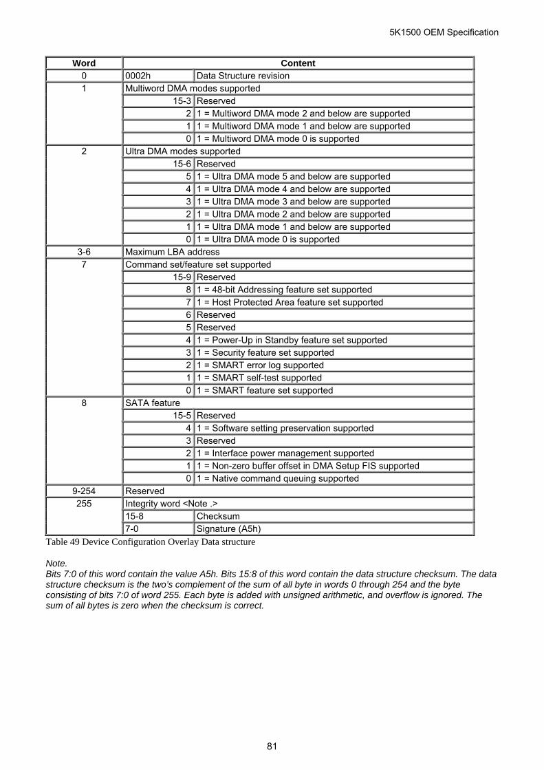
5K1500 OEM Specification
Word Content 0 0002h Data Structure revision 1 Multiword DMA modes supported 15-3 Reserved 2 1 = Multiword DMA mode 2 and below are supported 1 1 = Multiword DMA mode 1 and below are supported 0 1 = Multiword DMA mode 0 is supported 2 Ultra DMA modes supported 15-6 Reserved 5 1 = Ultra DMA mode 5 and below are supported 4 1 = Ultra DMA mode 4 and below are supported 3 1 = Ultra DMA mode 3 and below are supported 2 1 = Ultra DMA mode 2 and below are supported 1 1 = Ultra DMA mode 1 and below are supported 0 1 = Ultra DMA mode 0 is supported
3-6 Maximum LBA address 7 Command set/feature set supported 15-9 Reserved 8 1 = 48-bit Addressing feature set supported 7 1 = Host Protected Area feature set supported 6 Reserved 5 Reserved 4 1 = Power-Up in Standby feature set supported 3 1 = Security feature set supported 2 1 = SMART error log supported 1 1 = SMART self-test supported 0 1 = SMART feature set supported 8 SATA feature 15-5 Reserved 4 1 = Software setting preservation supported 3 Reserved 2 1 = Interface power management supported 1 1 = Non-zero buffer offset in DMA Setup FIS supported 0 1 = Native command queuing supported
9-254 Reserved 255 Integrity word <Note .>
15-8 Checksum 7-0 Signature (A5h)
Table 49 Device Configuration Overlay Data structure
Note. Bits 7:0 of this word contain the value A5h. Bits 15:8 of this word contain the data structure checksum. The data structure checksum is the two’s complement of the sum of all byte in words 0 through 254 and the byte consisting of bits 7:0 of word 255. Each byte is added with unsigned arithmetic, and overflow is ignored. The sum of all bytes is zero when the checksum is correct.
81
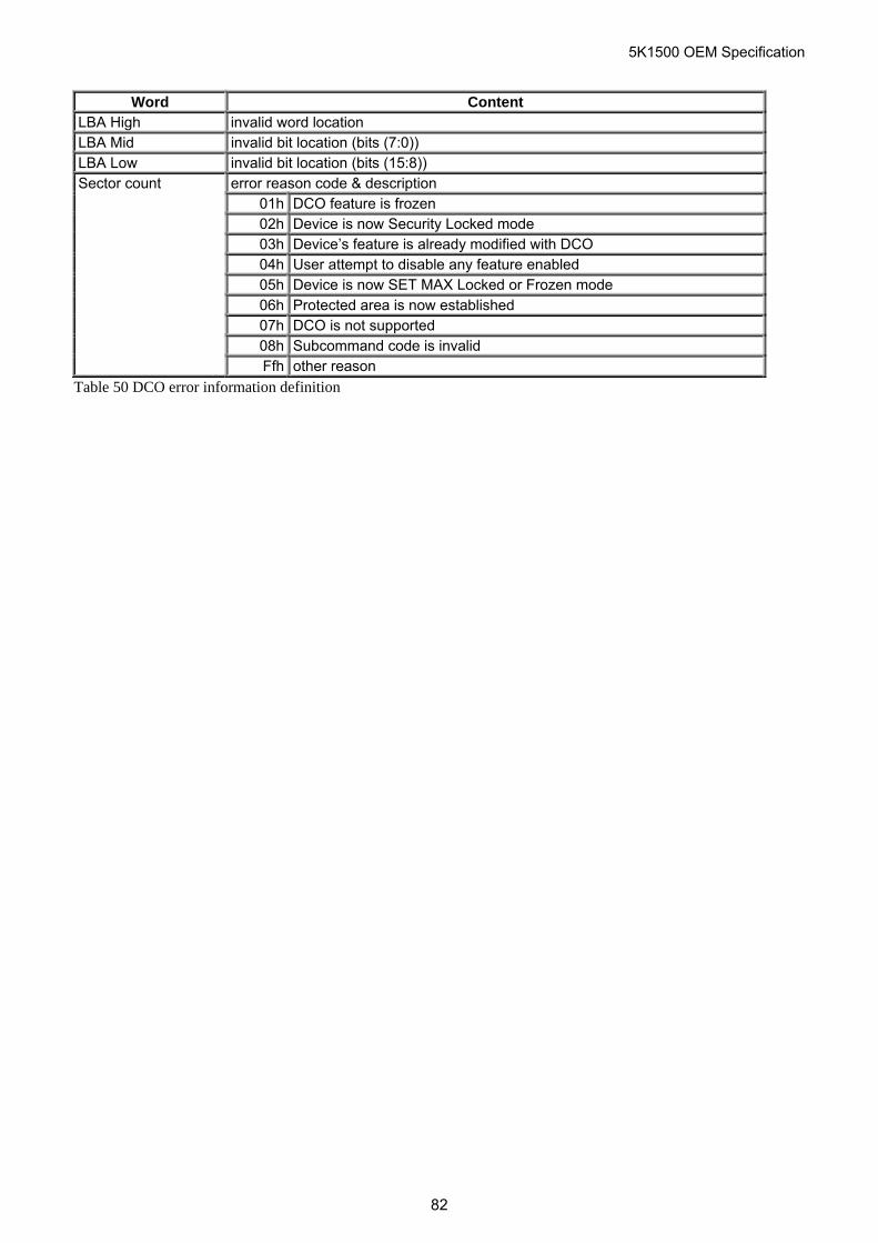
5K1500 OEM Specification
Word Content LBA High invalid word location LBA Mid invalid bit location (bits (7:0)) LBA Low invalid bit location (bits (15:8)) Sector count error reason code & description 01h DCO feature is frozen 02h Device is now Security Locked mode 03h Device’s feature is already modified with DCO 04h User attempt to disable any feature enabled 05h Device is now SET MAX Locked or Frozen mode 06h Protected area is now established 07h DCO is not supported 08h Subcommand code is invalid Ffh other reason
Table 50 DCO error information definition
82
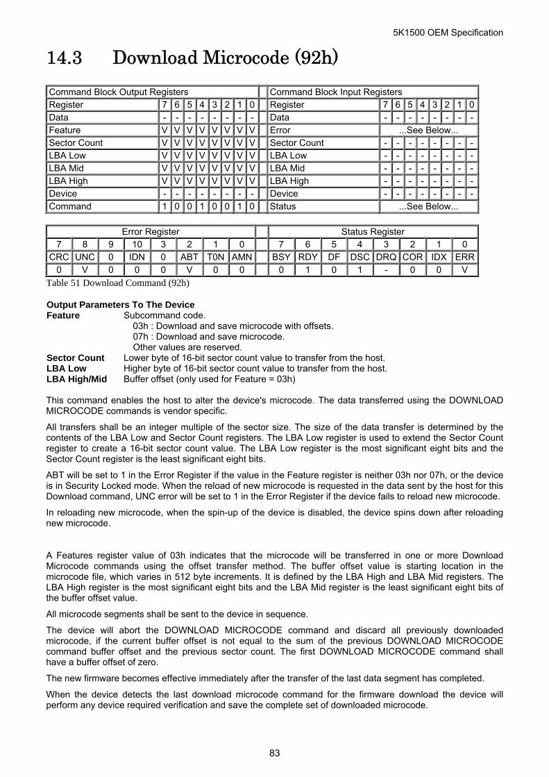
5K1500 OEM Specification
14.3 Download Microcode (92h) Command Block Output Registers Command Block Input Registers Register 7 6 5 4 3 2 1 0 Register 7 6 5 4 3 2 1 0Data - - - - - - - - Data - - - - - - - -Feature V V V V V V V V Error ...See Below... Sector Count V V V V V V V V Sector Count - - - - - - - -LBA Low V V V V V V V V LBA Low - - - - - - - -LBA Mid V V V V V V V V LBA Mid - - - - - - - -LBA High V V V V V V V V LBA High - - - - - - - -Device - - - - - - - - Device - - - - - - - -Command 1 0 0 1 0 0 1 0 Status ...See Below...
Error Register Status Register
7 8 9 10 3 2 1 0 7 6 5 4 3 2 1 0 CRC UNC 0 IDN 0 ABT T0N AMN BSY RDY DF DSC DRQ COR IDX ERR
0 V 0 0 0 V 0 0 0 1 0 1 - 0 0 V
Table 51 Download Command (92h)
Output Parameters To The Device Feature Subcommand code.
03h : Download and save microcode with offsets. 07h : Download and save microcode. Other values are reserved.
Sector Count Lower byte of 16-bit sector count value to transfer from the host. LBA Low Higher byte of 16-bit sector count value to transfer from the host. LBA High/Mid Buffer offset (only used for Feature = 03h) This command enables the host to alter the device's microcode. The data transferred using the DOWNLOAD MICROCODE commands is vendor specific.
All transfers shall be an integer multiple of the sector size. The size of the data transfer is determined by the contents of the LBA Low and Sector Count registers. The LBA Low register is used to extend the Sector Count register to create a 16-bit sector count value. The LBA Low register is the most significant eight bits and the Sector Count register is the least significant eight bits.
ABT will be set to 1 in the Error Register if the value in the Feature register is neither 03h nor 07h, or the device is in Security Locked mode. When the reload of new microcode is requested in the data sent by the host for this Download command, UNC error will be set to 1 in the Error Register if the device fails to reload new microcode.
In reloading new microcode, when the spin-up of the device is disabled, the device spins down after reloading new microcode.
A Features register value of 03h indicates that the microcode will be transferred in one or more Download Microcode commands using the offset transfer method. The buffer offset value is starting location in the microcode file, which varies in 512 byte increments. It is defined by the LBA High and LBA Mid registers. The LBA High register is the most significant eight bits and the LBA Mid register is the least significant eight bits of the buffer offset value.
All microcode segments shall be sent to the device in sequence.
The device will abort the DOWNLOAD MICROCODE command and discard all previously downloaded microcode, if the current buffer offset is not equal to the sum of the previous DOWNLOAD MICROCODE command buffer offset and the previous sector count. The first DOWNLOAD MICROCODE command shall have a buffer offset of zero.
The new firmware becomes effective immediately after the transfer of the last data segment has completed.
When the device detects the last download microcode command for the firmware download the device will perform any device required verification and save the complete set of downloaded microcode.
83
5K1500 OEM Specification
If the device receives a command other than download microcode prior to the receipt of the last segment the new command is executed and all previously downloaded microcode is discarded.
If a software or hardware Reset is issued to the device before all of the microcode segments have been transferred to the device the device shall abandon all of the microcode segments received and process the Reset.
84
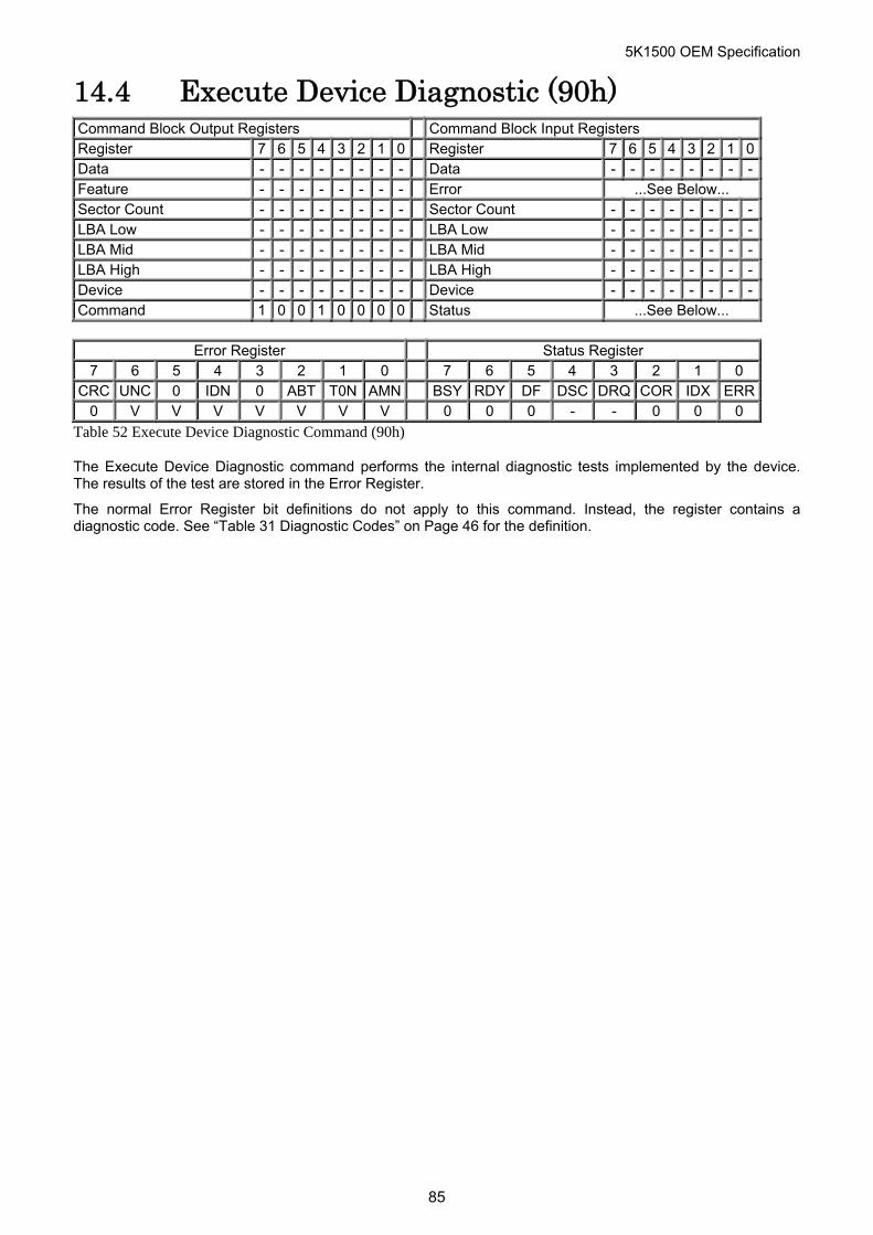
5K1500 OEM Specification
14.4 Execute Device Diagnostic (90h) Command Block Output Registers Command Block Input Registers Register 7 6 5 4 3 2 1 0 Register 7 6 5 4 3 2 1 0Data - - - - - - - - Data - - - - - - - -Feature - - - - - - - - Error ...See Below... Sector Count - - - - - - - - Sector Count - - - - - - - -LBA Low - - - - - - - - LBA Low - - - - - - - -LBA Mid - - - - - - - - LBA Mid - - - - - - - -LBA High - - - - - - - - LBA High - - - - - - - -Device - - - - - - - - Device - - - - - - - -Command 1 0 0 1 0 0 0 0 Status ...See Below...
Error Register Status Register
7 6 5 4 3 2 1 0 7 6 5 4 3 2 1 0 CRC UNC 0 IDN 0 ABT T0N AMN BSY RDY DF DSC DRQ COR IDX ERR
0 V V V V V V V 0 0 0 - - 0 0 0
Table 52 Execute Device Diagnostic Command (90h)
The Execute Device Diagnostic command performs the internal diagnostic tests implemented by the device. The results of the test are stored in the Error Register.
The normal Error Register bit definitions do not apply to this command. Instead, the register contains a diagnostic code. See “Table 31 Diagnostic Codes” on Page 46 for the definition.
85
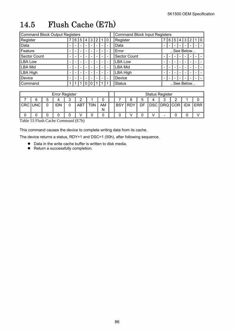
5K1500 OEM Specification
14.5 Flush Cache (E7h) Command Block Output Registers Command Block Input Registers Register 7 6 5 4 3 2 1 0 Register 7 6 5 4 3 2 1 0Data - - - - - - - - Data - - - - - - - -Feature - - - - - - - - Error ...See Below... Sector Count - - - - - - - - Sector Count - - - - - - - -LBA Low - - - - - - - - LBA Low - - - - - - - -LBA Mid - - - - - - - - LBA Mid - - - - - - - -LBA High - - - - - - - - LBA High - - - - - - - -Device - - - - - - - - Device - - - - - - - -Command 1 1 1 0 0 1 1 1 Status ...See Below...
Error Register Status Register
7 6 5 4 3 2 1 0 7 6 5 4 3 2 1 0 CRC UNC 0 IDN 0 ABT T0N AM
N BSY RDY DF DSC DRQ COR IDX ERR
0 0 0 0 0 V 0 0 0 V 0 V - 0 0 V
Table 53 Flush Cache Command (E7h)
This command causes the device to complete writing data from its cache.
The device returns a status, RDY=1 and DSC=1 (50h), after following sequence.
Data in the write cache buffer is written to disk media. Return a successfully completion.
86
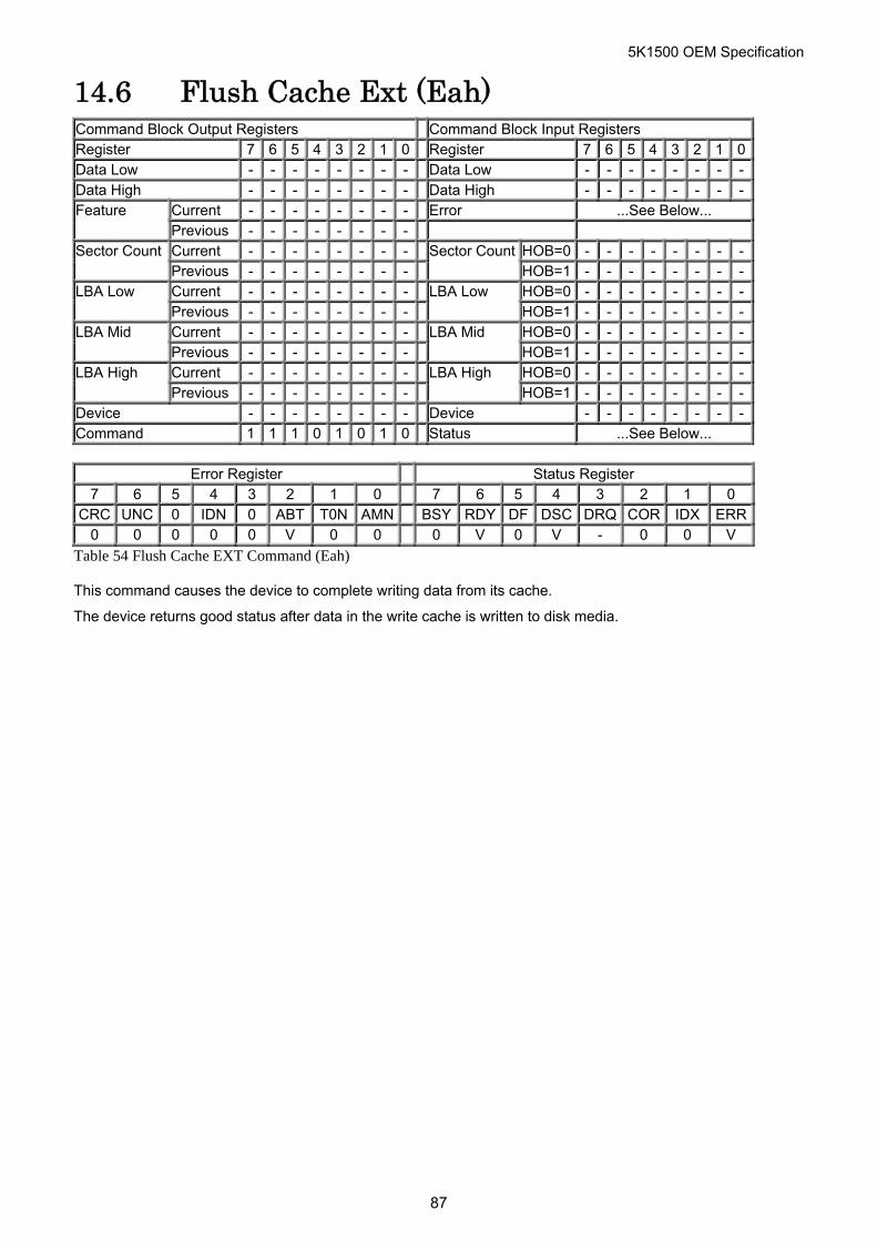
5K1500 OEM Specification
14.6 Flush Cache Ext (Eah) Command Block Output Registers Command Block Input Registers Register 7 6 5 4 3 2 1 0 Register 7 6 5 4 3 2 1 0Data Low - - - - - - - - Data Low - - - - - - - -Data High - - - - - - - - Data High - - - - - - - -
Current - - - - - - - - Error ...See Below... Feature Previous - - - - - - - - Current - - - - - - - - HOB=0 - - - - - - - -Sector Count Previous - - - - - - - -
Sector CountHOB=1 - - - - - - - -
Current - - - - - - - - HOB=0 - - - - - - - -LBA Low Previous - - - - - - - -
LBA Low HOB=1 - - - - - - - -
Current - - - - - - - - HOB=0 - - - - - - - -LBA Mid Previous - - - - - - - -
LBA Mid HOB=1 - - - - - - - -
Current - - - - - - - - HOB=0 - - - - - - - -LBA High Previous - - - - - - - -
LBA High HOB=1 - - - - - - - -
Device - - - - - - - - Device - - - - - - - -Command 1 1 1 0 1 0 1 0 Status ...See Below...
Error Register Status Register
7 6 5 4 3 2 1 0 7 6 5 4 3 2 1 0 CRC UNC 0 IDN 0 ABT T0N AMN BSY RDY DF DSC DRQ COR IDX ERR
0 0 0 0 0 V 0 0 0 V 0 V - 0 0 V
Table 54 Flush Cache EXT Command (Eah)
This command causes the device to complete writing data from its cache.
The device returns good status after data in the write cache is written to disk media.
87
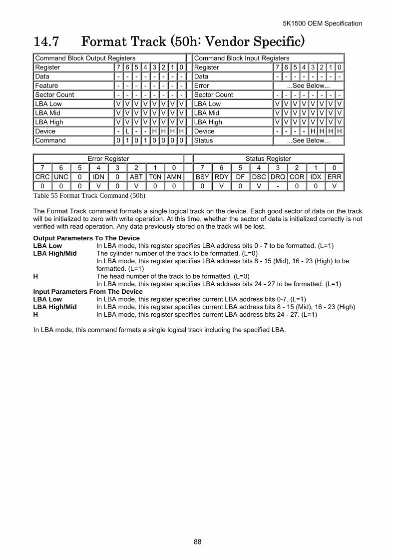
5K1500 OEM Specification
14.7 Format Track (50h: Vendor Specific) Command Block Output Registers Command Block Input Registers Register 7 6 5 4 3 2 1 0 Register 7 6 5 4 3 2 1 0Data - - - - - - - - Data - - - - - - - -Feature - - - - - - - - Error ...See Below... Sector Count - - - - - - - - Sector Count - - - - - - - -LBA Low V V V V V V V V LBA Low V V V V V V V VLBA Mid V V V V V V V V LBA Mid V V V V V V V VLBA High V V V V V V V V LBA High V V V V V V V VDevice - L - - H H H H Device - - - - H H H HCommand 0 1 0 1 0 0 0 0 Status ...See Below...
Error Register Status Register
7 6 5 4 3 2 1 0 7 6 5 4 3 2 1 0 CRC UNC 0 IDN 0 ABT T0N AMN BSY RDY DF DSC DRQ COR IDX ERR
0 0 0 V 0 V 0 0 0 V 0 V - 0 0 V
Table 55 Format Track Command (50h)
The Format Track command formats a single logical track on the device. Each good sector of data on the track will be initialized to zero with write operation. At this time, whether the sector of data is initialized correctly is not verified with read operation. Any data previously stored on the track will be lost.
Output Parameters To The Device LBA Low In LBA mode, this register specifies LBA address bits 0 - 7 to be formatted. (L=1) LBA High/Mid The cylinder number of the track to be formatted. (L=0)
In LBA mode, this register specifies LBA address bits 8 - 15 (Mid), 16 - 23 (High) to be formatted. (L=1)
H The head number of the track to be formatted. (L=0) In LBA mode, this register specifies LBA address bits 24 - 27 to be formatted. (L=1)
Input Parameters From The Device LBA Low In LBA mode, this register specifies current LBA address bits 0-7. (L=1) LBA High/Mid In LBA mode, this register specifies current LBA address bits 8 - 15 (Mid), 16 - 23 (High)H In LBA mode, this register specifies current LBA address bits 24 - 27. (L=1) In LBA mode, this command formats a single logical track including the specified LBA.
88
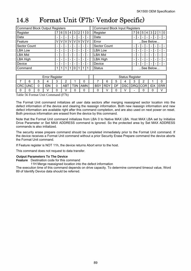
5K1500 OEM Specification
14.8 Format Unit (F7h: Vendor Specific) Command Block Output Registers Command Block Input Registers Register 7 6 5 4 3 2 1 0 Register 7 6 5 4 3 2 1 0Data - - - - - - - - Data - - - - - - - -Feature V V V V V V V V Error ...See Below... Sector Count - - - - - - - - Sector Count - - - - - - - -LBA Low - - - - - - - - LBA Low - - - - - - - -LBA Mid - - - - - - - - LBA Mid - - - - - - - -LBA High - - - - - - - - LBA High - - - - - - - -Device - - - - - - - - Device - - - - - - - -Command 1 1 1 1 0 1 1 1 Status ...See Below...
Error Register Status Register
7 6 5 4 3 2 1 0 7 6 5 4 3 2 1 0 CRC UNC 0 IDN 0 ABT T0N AMN BSY RDY DF DSC DRQ COR IDX ERR
0 0 0 V 0 V 0 0 0 V 0 V - 0 0 V
Table 56 Format Unit Command (F7h)
The Format Unit command initializes all user data sectors after merging reassigned sector location into the defect information of the device and clearing the reassign information. Both new reassign information and new defect information are available right after this command completion, and are also used on next power on reset. Both previous information are erased from the device by this command.
Note that the Format Unit command initializes from LBA 0 to Native MAX LBA. Host MAX LBA set by Initialize Drive Parameter or Set MAX ADDRESS command is ignored. So the protected area by Set MAX ADDRESS commands is also initialized.
The security erase prepare command should be completed immediately prior to the Format Unit command. If the device receives a Format Unit command without a prior Security Erase Prepare command the device aborts the Format Unit command.
If Feature register is NOT 11h, the device returns Abort error to the host.
This command does not request to data transfer.
Output Parameters To The Device Feature Destination code for this command 11H Merge reassigned location into the defect information The execution time of this command depends on drive capacity. To determine command timeout value, Word 89 of Identify Device data should be referred.
89
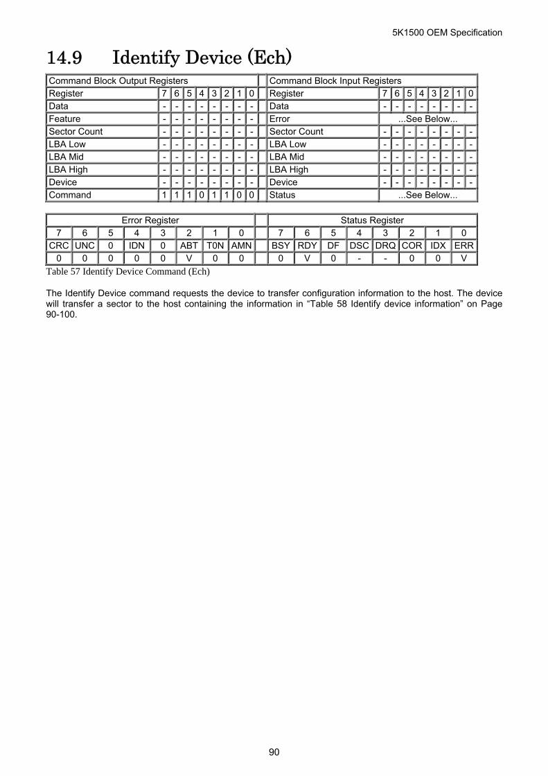
5K1500 OEM Specification
14.9 Identify Device (Ech) Command Block Output Registers Command Block Input Registers Register 7 6 5 4 3 2 1 0 Register 7 6 5 4 3 2 1 0Data - - - - - - - - Data - - - - - - - -Feature - - - - - - - - Error ...See Below... Sector Count - - - - - - - - Sector Count - - - - - - - -LBA Low - - - - - - - - LBA Low - - - - - - - -LBA Mid - - - - - - - - LBA Mid - - - - - - - -LBA High - - - - - - - - LBA High - - - - - - - -Device - - - - - - - - Device - - - - - - - -Command 1 1 1 0 1 1 0 0 Status ...See Below...
Error Register Status Register
7 6 5 4 3 2 1 0 7 6 5 4 3 2 1 0 CRC UNC 0 IDN 0 ABT T0N AMN BSY RDY DF DSC DRQ COR IDX ERR
0 0 0 0 0 V 0 0 0 V 0 - - 0 0 V
Table 57 Identify Device Command (Ech)
The Identify Device command requests the device to transfer configuration information to the host. The device will transfer a sector to the host containing the information in “Table 58 Identify device information” on Page 90-100.
90
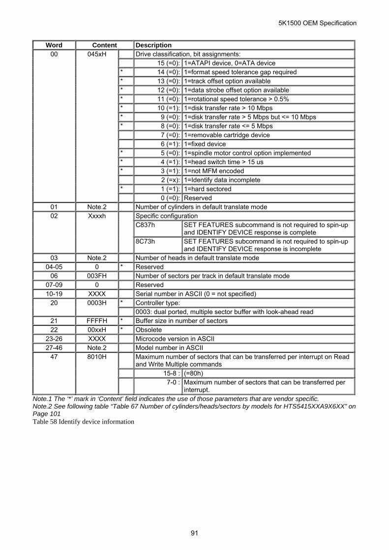
5K1500 OEM Specification
Word Content Description Drive classification, bit assignments: 15 (=0): 1=ATAPI device, 0=ATA device * 14 (=0): 1=format speed tolerance gap required * 13 (=0): 1=track offset option available * 12 (=0): 1=data strobe offset option available * 11 (=0): 1=rotational speed tolerance > 0.5% * 10 (=1): 1=disk transfer rate > 10 Mbps * 9 (=0): 1=disk transfer rate > 5 Mbps but <= 10 Mbps * 8 (=0): 1=disk transfer rate <= 5 Mbps 7 (=0): 1=removable cartridge device 6 (=1): 1=fixed device * 5 (=0): 1=spindle motor control option implemented * 4 (=1): 1=head switch time > 15 us * 3 (=1): 1=not MFM encoded 2 (=x): 1=Identify data incomplete * 1 (=1): 1=hard sectored
00
045xH
0 (=0): Reserved 01 Note.2 Number of cylinders in default translate mode
Specific configuration C837h SET FEATURES subcommand is not required to spin-up
and IDENTIFY DEVICE response is complete
02
Xxxxh
8C73h SET FEATURES subcommand is not required to spin-up and IDENTIFY DEVICE response is incomplete
03 Note.2 Number of heads in default translate mode 04-05 0 * Reserved
06 003FH Number of sectors per track in default translate mode 07-09 0 Reserved 10-19 XXXX Serial number in ASCII (0 = not specified)
20 0003H * Controller type: 0003: dual ported, multiple sector buffer with look-ahead read
21 FFFFH * Buffer size in number of sectors 22 00xxH * Obsolete
23-26 XXXX Microcode version in ASCII 27-46 Note.2 Model number in ASCII
47 8010H Maximum number of sectors that can be transferred per interrupt on Read and Write Multiple commands
15-8 : (=80h) 7-0 : Maximum number of sectors that can be transferred per
interrupt. Note.1 The ‘*’ mark in ‘Content’ field indicates the use of those parameters that are vendor specific. Note.2 See following table “Table 67 Number of cylinders/heads/sectors by models for HTS5415XXA9X6XX” on Page 101 Table 58 Identify device information
91
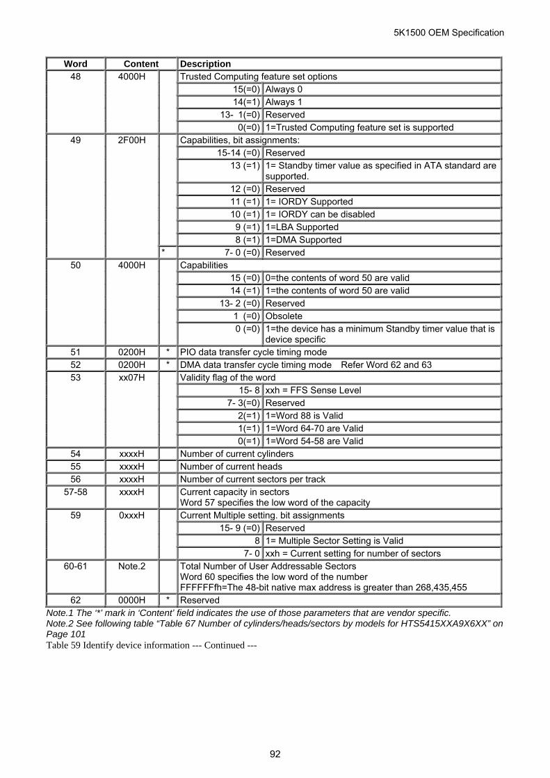
5K1500 OEM Specification
Word Content Description Trusted Computing feature set options
15(=0) Always 0 14(=1) Always 1
13- 1(=0) Reserved
48 4000H
0(=0) 1=Trusted Computing feature set is supported Capabilities, bit assignments:
15-14 (=0) Reserved 13 (=1) 1= Standby timer value as specified in ATA standard are
supported. 12 (=0) Reserved 11 (=1) 1= IORDY Supported 10 (=1) 1= IORDY can be disabled
9 (=1) 1=LBA Supported
8 (=1) 1=DMA Supported
49
2F00H
* 7- 0 (=0) Reserved Capabilities
15 (=0) 0=the contents of word 50 are valid 14 (=1) 1=the contents of word 50 are valid
13- 2 (=0) Reserved 1 (=0) Obsolete
50
4000H
0 (=0) 1=the device has a minimum Standby timer value that is device specific
51 0200H * PIO data transfer cycle timing mode 52 0200H * DMA data transfer cycle timing mode Refer Word 62 and 63
Validity flag of the word 15- 8 xxh = FFS Sense Level
7- 3(=0) Reserved 2(=1) 1=Word 88 is Valid 1(=1) 1=Word 64-70 are Valid
53
xx07H
0(=1) 1=Word 54-58 are Valid 54 xxxxH Number of current cylinders 55 xxxxH Number of current heads 56 xxxxH Number of current sectors per track
57-58 xxxxH Current capacity in sectors Word 57 specifies the low word of the capacity Current Multiple setting. bit assignments
15- 9 (=0) Reserved 8 1= Multiple Sector Setting is Valid
59
0xxxH
7- 0 xxh = Current setting for number of sectors 60-61 Note.2 Total Number of User Addressable Sectors
Word 60 specifies the low word of the number FFFFFFfh=The 48-bit native max address is greater than 268,435,455
62 0000H * Reserved Note.1 The ‘*’ mark in ‘Content’ field indicates the use of those parameters that are vendor specific. Note.2 See following table “Table 67 Number of cylinders/heads/sectors by models for HTS5415XXA9X6XX” on Page 101 Table 59 Identify device information --- Continued ---
92
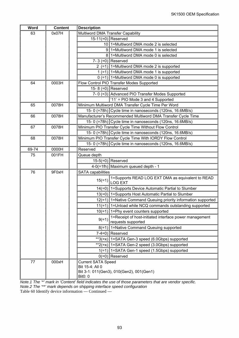
5K1500 OEM Specification
Word Content Description Multiword DMA Transfer Capability
15-11(=0) Reserved 10 1=Multiword DMA mode 2 is selected
9 1=Multiword DMA mode 1 is selected 8 1=Multiword DMA mode 0 is selected
7- 3 (=0) Reserved 2 (=1) 1=Multiword DMA mode 2 is supported 1 (=1) 1=Multiword DMA mode 1 is supported
63
0x07H
0 (=1) 1=Multiword DMA mode 0 is supported Flow Control PIO Transfer Modes Supported
15- 8 (=0) Reserved 7- 0 (=3) Advanced PIO Transfer Modes Supported
64
0003H
‘11’ = PIO Mode 3 and 4 Supported Minimum Multiword DMA Transfer Cycle Time Per Word 65
0078H
15- 0 (=78h) Cycle time in nanoseconds (120ns, 16.6MB/s) Manufacturer’s Recommended Multiword DMA Transfer Cycle Time 66
0078H
15- 0 (=78h) Cycle time in nanoseconds (120ns, 16.6MB/s) Minimum PIO Transfer Cycle Time Without Flow Control 67
0078H
15- 0 (=78h) Cycle time in nanoseconds (120ns, 16.6MB/s) Minimum PIO Transfer Cycle Time With IORDY Flow Control 68 0078H
15- 0 (=78h) Cycle time in nanoseconds (120ns, 16.6MB/s) 69-74 0000H Reserved
Queue depth
15-5(=0) Reserved
75 001FH
4-0(=1fh) Maximum queued depth - 1
SATA capabilities
15(=1)1=Supports READ LOG EXT DMA as equivalent to READ LOG EXT
14(=0) 1=Supports Device Automatic Partial to Slumber
13(=0) 1=Supports Host Automatic Partial to Slumber
12(=1) 1=Native Command Queuing priority information supported
11(=1) 1=Unload while NCQ commands outstanding supported
10(=1) 1=Phy event counters supported
9(=1)1=Receipt of host-initiated interface power management requests supported
8(=1) 1=Native Command Queuing supported
7-4=0) Reserved
**3(=x) 1=SATA Gen-3 speed (6.0Gbps) supported
**2(=x) 1=SATA Gen-2 speed (3.0Gbps) supported
1(=1) 1=SATA Gen-1 speed (1.5Gbps) supported
76 9F0xH
0(=0) Reserved
77 000xH Current SATA Speed Bit 15-4: All 0 Bit 3-1: 011(Gen3), 010(Gen2), 001(Gen1) Bit0: 0
Note.1 The ‘*’ mark in ‘Content’ field indicates the use of those parameters that are vendor specific. Note.2 The ‘**’ mark depends on shipping interface speed configuration Table 60 Identify device information --- Continued ---
93
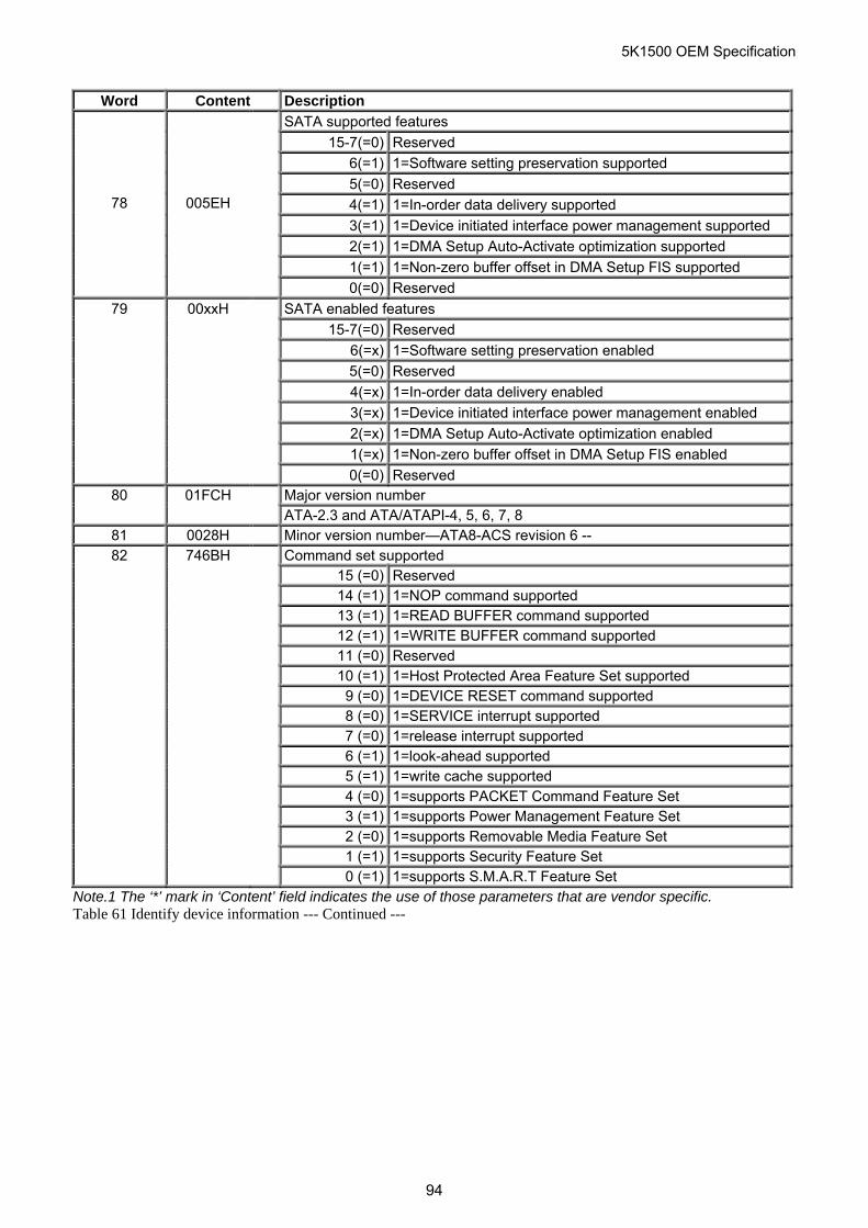
5K1500 OEM Specification
Word Content Description
SATA supported features
15-7(=0) Reserved
6(=1) 1=Software setting preservation supported
5(=0) Reserved
4(=1) 1=In-order data delivery supported
3(=1) 1=Device initiated interface power management supported
2(=1) 1=DMA Setup Auto-Activate optimization supported
1(=1) 1=Non-zero buffer offset in DMA Setup FIS supported
78 005EH
0(=0) Reserved
79 00xxH SATA enabled features
15-7(=0) Reserved
6(=x) 1=Software setting preservation enabled
5(=0) Reserved
4(=x) 1=In-order data delivery enabled
3(=x) 1=Device initiated interface power management enabled
2(=x) 1=DMA Setup Auto-Activate optimization enabled
1(=x) 1=Non-zero buffer offset in DMA Setup FIS enabled
0(=0) Reserved 80 01FCH Major version number ATA-2.3 and ATA/ATAPI-4, 5, 6, 7, 8
81 0028H Minor version number—ATA8-ACS revision 6 -- 82 746BH Command set supported
15 (=0) Reserved 14 (=1) 1=NOP command supported 13 (=1) 1=READ BUFFER command supported 12 (=1) 1=WRITE BUFFER command supported 11 (=0) Reserved 10 (=1) 1=Host Protected Area Feature Set supported 9 (=0) 1=DEVICE RESET command supported 8 (=0) 1=SERVICE interrupt supported 7 (=0) 1=release interrupt supported 6 (=1) 1=look-ahead supported 5 (=1) 1=write cache supported 4 (=0) 1=supports PACKET Command Feature Set 3 (=1) 1=supports Power Management Feature Set 2 (=0) 1=supports Removable Media Feature Set 1 (=1) 1=supports Security Feature Set 0 (=1) 1=supports S.M.A.R.T Feature Set
Note.1 The ‘*’ mark in ‘Content’ field indicates the use of those parameters that are vendor specific. Table 61 Identify device information --- Continued ---
94
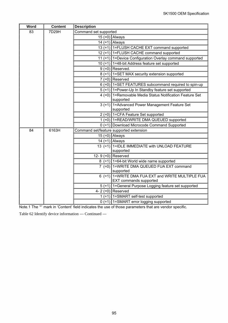
5K1500 OEM Specification
Word Content Description Command set supported
15 (=0) Always 14 (=1) Always 13 (=1) 1=FLUSH CACHE EXT command supported 12 (=1) 1=FLUSH CACHE command supported 11 (=1) 1=Device Configuration Overlay command supported 10 (=1) 1=48-bit Address feature set supported
9 (=0) Reserved. 8 (=1) 1=SET MAX security extension supported
7 (=0) Reserved 6 (=0) 1=SET FEATURES subcommand required to spin-up 5 (=1) 1=Power-Up In Standby feature set supported 4 (=0) 1=Removable Media Status Notification Feature Set
supported 3 (=1) 1=Advanced Power Management Feature Set
supported 2 (=0) 1=CFA Feature Set supported 1 (=0) 1=READ/WRITE DMA QUEUED supported
83
7D29H
0 (=1) Download Microcode Command Supported Command set/feature supported extension
15 (=0) Always 14 (=1) Always 13 (=1) 1=IDLE IMMEDIATE with UNLOAD FEATURE
supported 12- 9 (=0) Reserved
8 (=1) 1=64-bit World wide name supported 7 (=0) 1=WRITE DMA QUEUED FUA EXT command
supported 6 (=1) 1=WRITE DMA FUA EXT and WRITE MULTIPLE FUA
EXT commands supported 5 (=1) 1=General Purpose Logging feature set supported
4- 2 (=0) Reserved 1 (=1) 1=SMART self-test supported
84
6163H
0 (=1) 1=SMART error logging supported Note.1 The ‘*’ mark in ‘Content’ field indicates the use of those parameters that are vendor specific.
Table 62 Identify device information --- Continued ---
95
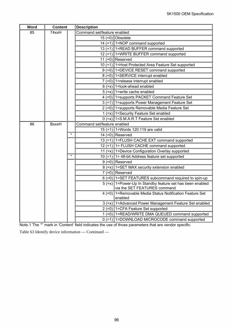
5K1500 OEM Specification
Word Content Description 85 74xxH Command set/feature enabled
15 (=0) Obsolete 14 (=1) 1=NOP command supported 13 (=1) 1=READ BUFFER command supported 12 (=1) 1=WRITE BUFFER command supported 11 (=0) Reserved 10 (=1) 1=Host Protected Area Feature Set supported 9 (=0) 1=DEVICE RESET command supported 8 (=0) 1=SERVICE interrupt enabled 7 (=0) 1=release interrupt enabled 6 (=x) 1=look-ahead enabled 5 (=x) 1=write cache enabled 4 (=0) 1=supports PACKET Command Feature Set 3 (=1) 1=supports Power Management Feature Set 2 (=0) 1=supports Removable Media Feature Set 1 (=x) 1=Security Feature Set enabled 0 (=x) 1=S.M.A.R.T Feature Set enabled
86 BxxxH Command set/feature enabled 15 (=1) 1=Words 120:119 are valid * 14 (=0) Reserved
13 (=1) 1=FLUSH CACHE EXT command supported 12 (=1) 1= FLUSH CACHE command supported 11 (=x) 1=Device Configuration Overlay supported
* 10 (=1) 1= 48-bit Address feature set supported 9 (=0) Reserved
8 (=x) 1=SET MAX security extension enabled 7 (=0) Reserved 6 (=0) 1=SET FEATURES subcommand required to spin-up 5 (=x) 1=Power-Up In Standby feature set has been enabled
via the SET FEATURES command 4 (=0) 1=Removable Media Status Notification Feature Set
enabled 3 (=x) 1=Advanced Power Management Feature Set enabled 2 (=0) 1=CFA Feature Set supported 1 (=0) 1=READ/WRITE DMA QUEUED command supported 0 (=1) 1=DOWNLOAD MICROCODE command supported
Note.1 The ‘*’ mark in ‘Content’ field indicates the use of those parameters that are vendor specific.
Table 63 Identify device information --- Continued ---
96
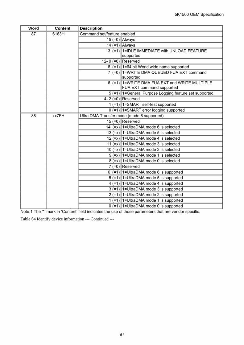
5K1500 OEM Specification
Word Content Description 87 6163H Command set/feature enabled
15 (=0) Always 14 (=1) Always 13 (=1) 1=IDLE IMMEDIATE with UNLOAD FEATURE
supported 12- 9 (=0) Reserved 8 (=1) 1=64 bit World wide name supported 7 (=0) 1=WRITE DMA QUEUED FUA EXT command
supported 6 (=1) 1=WRITE DMA FUA EXT and WRITE MULTIPLE
FUA EXT command supported 5 (=1) 1=General Purpose Logging feature set supported 4- 2 (=0) Reserved 1 (=1) 1=SMART self-test supported 0 (=1) 1=SMART error logging supported
88 xx7FH Ultra DMA Transfer mode (mode 6 supported) 15 (=0) Reserved 14 (=x) 1=UltraDMA mode 6 is selected 13 (=x) 1=UltraDMA mode 5 is selected 12 (=x) 1=UltraDMA mode 4 is selected 11 (=x) 1=UltraDMA mode 3 is selected 10 (=x) 1=UltraDMA mode 2 is selected 9 (=x) 1=UltraDMA mode 1 is selected 8 (=x) 1=UltraDMA mode 0 is selected 7 (=0) Reserved 6 (=1) 1=UltraDMA mode 6 is supported 5 (=1) 1=UltraDMA mode 5 is supported 4 (=1) 1=UltraDMA mode 4 is supported 3 (=1) 1=UltraDMA mode 3 is supported 2 (=1) 1=UltraDMA mode 2 is supported 1 (=1) 1=UltraDMA mode 1 is supported 0 (=1) 1=UltraDMA mode 0 is supported
Note.1 The ‘*’ mark in ‘Content’ field indicates the use of those parameters that are vendor specific.
Table 64 Identify device information --- Continued ---
97
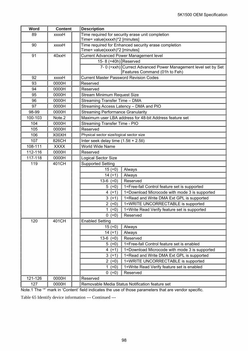
5K1500 OEM Specification
Word Content Description 89 xxxxH Time required for security erase unit completion
Time= value(xxxxh)*2 [minutes] 90 xxxxH Time required for Enhanced security erase completion
Time= value(xxxxh)*2 [minutes] 91 40xxH Current Advanced Power Management level
15- 8 (=40h) Reserved 7- 0 (=xxh) Currect Advanced Power Management level set by Set
Features Command (01h to Feh) 92 xxxxH Current Master Password Revision Codes 93 0000H Reserved 94 0000H Reserved 95 0000H Stream Minimum Request Size 96 0000H Streaming Transfer Time – DMA 97 0000H Streaming Access Latency – DMA and PIO
98-99 0000H Streaming Performance Granularity 100-103 Note.2 Maximum user LBA address for 48-bit Address feature set
104 0000H Streaming Transfer Time - PIO 105 0000H Reserved 106 X00XH Physical sector size/logical sector size
107 826CH Inter seek delay time (1.5tt + 2.5tl) 108-111 XXXX World Wide Name 112-116 0000H Reserved 117-118 0000H Logical Sector Size
119 401CH Supported Setting 15 (=0) Always 14 (=1) Always 13-6 (=0) Reserved 5 (=0) 1=Free-fall Control feature set is supported 4 (=1) 1=Download Microcode with mode 3 is supported 3 (=1) 1=Read and Write DMA Ext GPL is supported 2 (=0) 1=WRITE UNCORRECTABLE is supported 1 (=0) 1=Write Read Verify feature set is supported 0 (=0) Reserved
120 401CH Enabled Setting 15 (=0) Always 14 (=1) Always 13-6 (=0) Reserved 5 (=0) 1=Free-fall Control feature set is enabled 4 (=1) 1=Download Microcode with mode 3 is supported 3 (=1) 1=Read and Write DMA Ext GPL is supported 2 (=0) 1=WRITE UNCORRECTABLE is supported 1 (=0) 1=Write Read Verify feature set is enabled 0 (=0) Reserved
121-126 0000H Reserved 127 0000H Removable Media Status Notification feature set
Note.1 The ‘*’ mark in ‘Content’ field indicates the use of those parameters that are vendor specific.
Table 65 Identify device information --- Continued ---
98
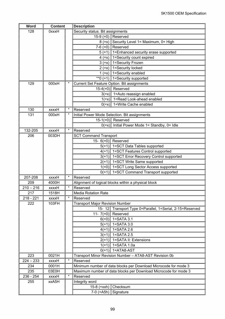
5K1500 OEM Specification
Word Content Description 128 0xxxH Security status. Bit assignments
15-9 (=0) Reserved 8 (=x) Security Level 1= Maximum, 0= High 7-6 (=0) Reserved 5 (=1) 1=Enhanced security erase supported 4 (=x) 1=Security count expired 3 (=x) 1=Security Frozen 2 (=x) 1=Security locked 1 (=x) 1=Security enabled **0 (=1) 1=Security supported
129 000xH * Current Set Feature Option. Bit assignments 15-4(=0) Reserved 3(=x) 1=Auto reassign enabled 1(=x) 1=Read Look-ahead enabled 0(=x) 1=Write Cache enabled
130 xxxxH * Reserved 131 000xH * Initial Power Mode Selection. Bit assignments
15-1(=0) Reserved 0(=x) Initial Power Mode 1= Standby, 0= Idle
132-205 xxxxH * Reserved 206 003DH SCT Command Transport
15- 6(=0) Reserved 5(=1) 1=SCT Data Tables supported 4(=1) 1=SCT Features Control supported 3(=1) 1=SCT Error Recovery Control supported 2(=1) 1=SCT Write Same supported 1(=0) 1=SCT Long Sector Access supported 0(=1) 1=SCT Command Transport supported
207-208 xxxxH * Reserved 209 4000H Alignment of logical blocks within a physical block
210 – 216 xxxxH * Reserved 217 1518H Media Rotation Rate
218 - 221 xxxxH * Reserved 222 103FH Transport Major Revision Number
15- 12 Transport Type 0=Parallel, 1=Serial, 2-15=Reserved 11- 7(=0) Reserved 6(=0) 1=SATA 3.1 5(=1) 1=SATA 3.0 4(=1) 1=SATA 2.6 3(=1) 1=SATA 2.5 2(=1) 1=SATA II: Extensions 1(=1) 1=SATA 1.0a 0(=1) 1=ATA8-AST
223 0021H Transport Minor Revision Number – ATA8-AST Revision 0b 224 – 233 xxxxH * Reserved
234 0001H Minimum number of data blocks per Download Microcode for mode 3 235 03E0H Maximum number of data blocks per Download Microcode for mode 3
236 - 254 xxxxH * Reserved 255 xxA5H Integrity word
15-8 (=xxh) Checksum 7-0 (=A5h) Signature
99
5K1500 OEM Specification
Note.1 The ‘*’ mark in ‘Content’ field indicates the use of those parameters that are vendor specific. Table 66 Identify device information --- Continued ---
100
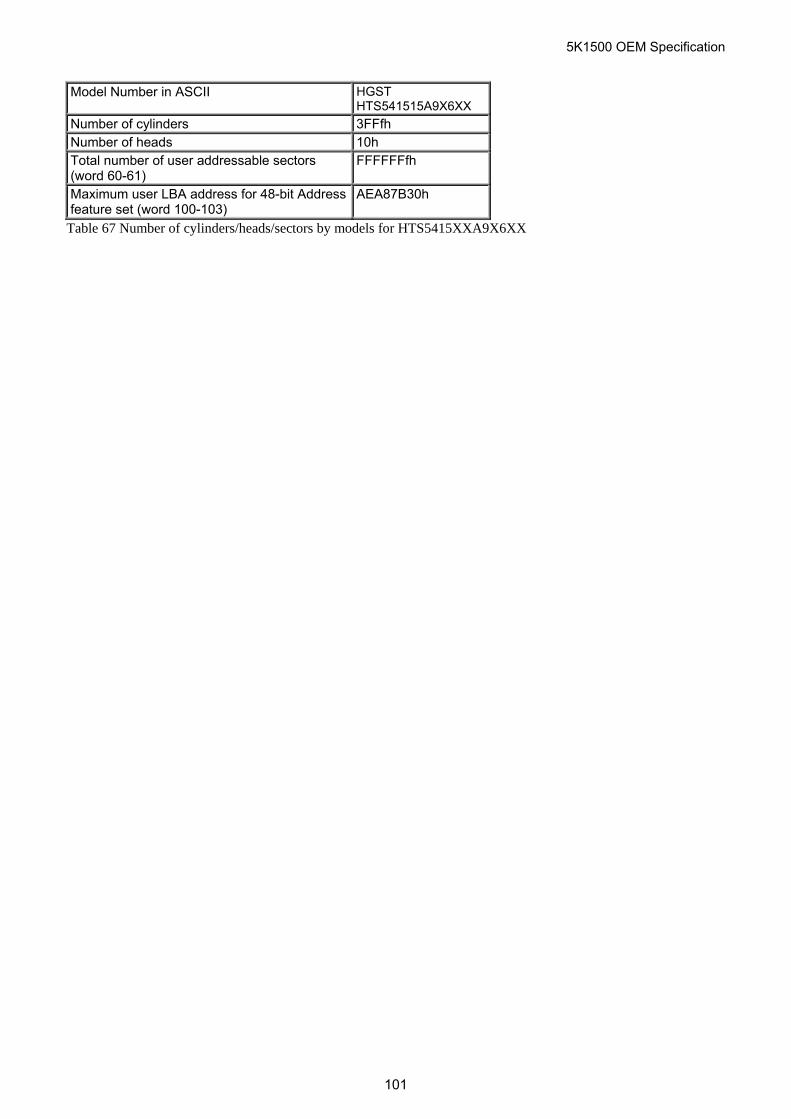
5K1500 OEM Specification
Model Number in ASCII HGST
HTS541515A9X6XX
Number of cylinders 3FFfh Number of heads 10h Total number of user addressable sectors (word 60-61)
FFFFFFfh
Maximum user LBA address for 48-bit Address feature set (word 100-103)
AEA87B30h
Table 67 Number of cylinders/heads/sectors by models for HTS5415XXA9X6XX
101
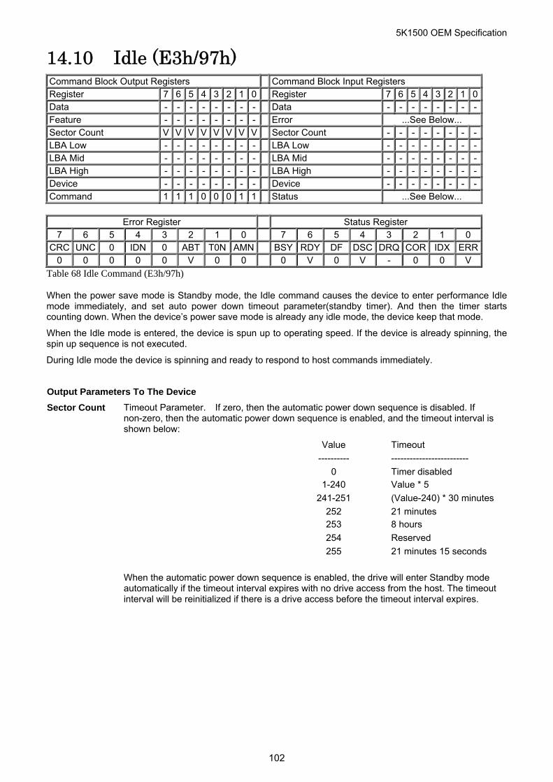
5K1500 OEM Specification
14.10 Idle (E3h/97h) Command Block Output Registers Command Block Input Registers Register 7 6 5 4 3 2 1 0 Register 7 6 5 4 3 2 1 0Data - - - - - - - - Data - - - - - - - -Feature - - - - - - - - Error ...See Below... Sector Count V V V V V V V V Sector Count - - - - - - - -LBA Low - - - - - - - - LBA Low - - - - - - - -LBA Mid - - - - - - - - LBA Mid - - - - - - - -LBA High - - - - - - - - LBA High - - - - - - - -Device - - - - - - - - Device - - - - - - - -Command 1 1 1 0 0 0 1 1 Status ...See Below...
Error Register Status Register
7 6 5 4 3 2 1 0 7 6 5 4 3 2 1 0 CRC UNC 0 IDN 0 ABT T0N AMN BSY RDY DF DSC DRQ COR IDX ERR
0 0 0 0 0 V 0 0 0 V 0 V - 0 0 V
Table 68 Idle Command (E3h/97h)
When the power save mode is Standby mode, the Idle command causes the device to enter performance Idle mode immediately, and set auto power down timeout parameter(standby timer). And then the timer starts counting down. When the device’s power save mode is already any idle mode, the device keep that mode.
When the Idle mode is entered, the device is spun up to operating speed. If the device is already spinning, the spin up sequence is not executed.
During Idle mode the device is spinning and ready to respond to host commands immediately.
Output Parameters To The Device
Sector Count Timeout Parameter. If zero, then the automatic power down sequence is disabled. If non-zero, then the automatic power down sequence is enabled, and the timeout interval is shown below:
Value Timeout
---------- -------------------------
0 Timer disabled
1-240 Value * 5
241-251 (Value-240) * 30 minutes
252 21 minutes
253 8 hours
254 Reserved
255 21 minutes 15 seconds
When the automatic power down sequence is enabled, the drive will enter Standby mode
automatically if the timeout interval expires with no drive access from the host. The timeout interval will be reinitialized if there is a drive access before the timeout interval expires.
102
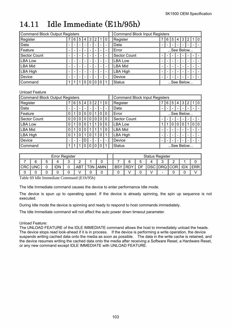
5K1500 OEM Specification
14.11 Idle Immediate (E1h/95h) Command Block Output Registers Command Block Input Registers Register 7 6 5 4 3 2 1 0 Register 7 6 5 4 3 2 1 0Data - - - - - - - - Data - - - - - - - -Feature - - - - - - - - Error ...See Below... Sector Count - - - - - - - - Sector Count - - - - - - - -LBA Low - - - - - - - - LBA Low - - - - - - - -LBA Mid - - - - - - - - LBA Mid - - - - - - - -LBA High - - - - - - - - LBA High - - - - - - - -Device - - - - - - - - Device - - - - - - - -Command 1 1 1 0 0 0 0 1 Status ...See Below...
Unload Feature Command Block Output Registers Command Block Input Registers Register 7 6 5 4 3 2 1 0 Register 7 6 5 4 3 2 1 0Data - - - - - - - - Data - - - - - - - -Feature 0 1 0 0 0 1 0 0 Error ...See Below... Sector Count 0 0 0 0 0 0 0 0 Sector Count - - - - - - - -LBA Low 0 1 0 0 1 1 0 0 LBA Low 1 1 0 0 0 1 0 0LBA Mid 0 1 0 0 1 1 1 0 LBA Mid - - - - - - - -LBA High 0 1 0 1 0 1 0 1 LBA High - - - - - - - -Device - - - D - - - - Device - - - - - - - -Command 1 1 1 0 0 0 0 1 Status ...See Below...
Error Register Status Register
7 6 5 4 3 2 1 0 7 6 5 4 3 2 1 0 CRC UNC 0 IDN 0 ABT T0N AMN BSY RDY DF DSC DRQ COR IDX ERR
0 0 0 0 0 V 0 0 0 V 0 V - 0 0 V
Table 69 Idle Immediate Command (E1h/95h)
The Idle Immediate command causes the device to enter performance Idle mode.
The device is spun up to operating speed. If the device is already spinning, the spin up sequence is not executed.
During Idle mode the device is spinning and ready to respond to host commands immediately.
The Idle Immediate command will not affect the auto power down timeout parameter.
Unload Feature: The UNLOAD FEATURE of the IDLE IMMEDIATE command allows the host to immediately unload the heads. The device stops read look-ahead if it is in process. If the device is performing a write operation, the device suspends writing cached data onto the media as soon as possible. The data in the write cache is retained, and the device resumes writing the cached data onto the media after receiving a Software Reset, a Hardware Reset, or any new command except IDLE IMMEDIATE with UNLOAD FEATURE.
103
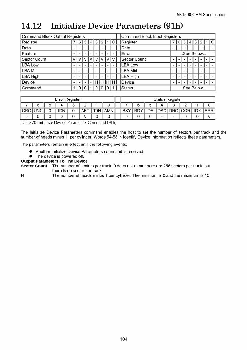
5K1500 OEM Specification
14.12 Initialize Device Parameters (91h) Command Block Output Registers Command Block Input Registers Register 7 6 5 4 3 2 1 0 Register 7 6 5 4 3 2 1 0Data - - - - - - - - Data - - - - - - - -Feature - - - - - - - - Error ...See Below... Sector Count V V V V V V V V Sector Count - - - - - - - -LBA Low - - - - - - - - LBA Low - - - - - - - -LBA Mid - - - - - - - - LBA Mid - - - - - - - -LBA High - - - - - - - - LBA High - - - - - - - -Device - - - - H H H H Device - - - - - - - -Command 1 0 0 1 0 0 0 1 Status ...See Below...
Error Register Status Register
7 6 5 4 3 2 1 0 7 6 5 4 3 2 1 0 CRC UNC 0 IDN 0 ABT T0N AMN BSY RDY DF DSC DRQ COR IDX ERR
0 0 0 0 0 V 0 0 0 0 0 - - 0 0 V
Table 70 Initialize Device Parameters Command (91h)
The Initialize Device Parameters command enables the host to set the number of sectors per track and the number of heads minus 1, per cylinder. Words 54-58 in Identify Device Information reflects these parameters.
The parameters remain in effect until the following events:
Another Initialize Device Parameters command is received. The device is powered off.
Output Parameters To The Device Sector Count The number of sectors per track. 0 does not mean there are 256 sectors per track, but
there is no sector per track. H The number of heads minus 1 per cylinder. The minimum is 0 and the maximum is 15.
104
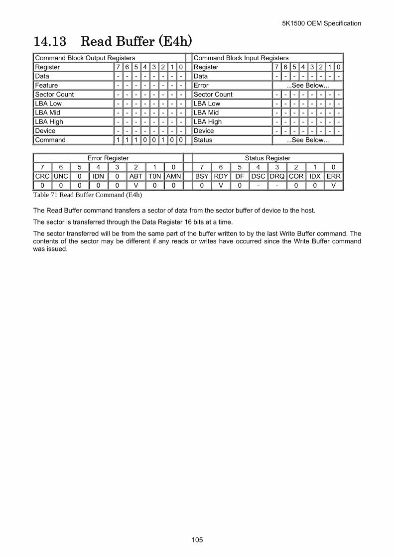
5K1500 OEM Specification
14.13 Read Buffer (E4h) Command Block Output Registers Command Block Input Registers Register 7 6 5 4 3 2 1 0 Register 7 6 5 4 3 2 1 0Data - - - - - - - - Data - - - - - - - -Feature - - - - - - - - Error ...See Below... Sector Count - - - - - - - - Sector Count - - - - - - - -LBA Low - - - - - - - - LBA Low - - - - - - - -LBA Mid - - - - - - - - LBA Mid - - - - - - - -LBA High - - - - - - - - LBA High - - - - - - - -Device - - - - - - - - Device - - - - - - - -Command 1 1 1 0 0 1 0 0 Status ...See Below...
Error Register Status Register
7 6 5 4 3 2 1 0 7 6 5 4 3 2 1 0 CRC UNC 0 IDN 0 ABT T0N AMN BSY RDY DF DSC DRQ COR IDX ERR
0 0 0 0 0 V 0 0 0 V 0 - - 0 0 V
Table 71 Read Buffer Command (E4h)
The Read Buffer command transfers a sector of data from the sector buffer of device to the host.
The sector is transferred through the Data Register 16 bits at a time.
The sector transferred will be from the same part of the buffer written to by the last Write Buffer command. The contents of the sector may be different if any reads or writes have occurred since the Write Buffer command was issued.
105
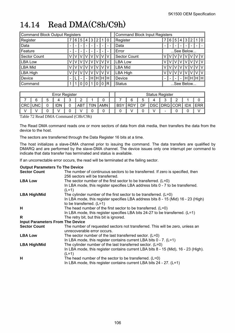
5K1500 OEM Specification
14.14 Read DMA(C8h/C9h) Command Block Output Registers Command Block Input Registers Register 7 6 5 4 3 2 1 0 Register 7 6 5 4 3 2 1 0Data - - - - - - - - Data - - - - - - - -Feature - - - - - - - - Error ...See Below... Sector Count V V V V V V V V Sector Count V V V V V V V VLBA Low V V V V V V V V LBA Low V V V V V V V VLBA Mid V V V V V V V V LBA Mid V V V V V V V VLBA High V V V V V V V V LBA High V V V V V V V VDevice - L - - H H H H Device - - - - H H H HCommand 1 1 0 0 1 0 0 R Status ...See Below...
Error Register Status Register
7 6 5 4 3 2 1 0 7 6 5 4 3 2 1 0 CRC UNC 0 IDN 0 ABT T0N AMN BSY RDY DF DSC DRQ COR IDX ERR
V V 0 V 0 V 0 0 0 V 0 V - 0 0 V
Table 72 Read DMA Command (C8h/C9h)
The Read DMA command reads one or more sectors of data from disk media, then transfers the data from the device to the host.
The sectors are transferred through the Data Register 16 bits at a time.
The host initializes a slave-DMA channel prior to issuing the command. The data transfers are qualified by DMARQ and are performed by the slave-DMA channel. The device issues only one interrupt per command to indicate that data transfer has terminated and status is available.
If an uncorrectable error occurs, the read will be terminated at the failing sector.
Output Parameters To The Device Sector Count The number of continuous sectors to be transferred. If zero is specified, then
256 sectors will be transferred. LBA Low The sector number of the first sector to be transferred. (L=0)
In LBA mode, this register specifies LBA address bits 0 - 7 to be transferred. (L=1)
LBA High/Mid The cylinder number of the first sector to be transferred. (L=0) In LBA mode, this register specifies LBA address bits 8 - 15 (Mid) 16 - 23 (High) to be transferred. (L=1)
H The head number of the first sector to be transferred. (L=0) In LBA mode, this register specifies LBA bits 24-27 to be transferred. (L=1)
R The retry bit, but this bit is ignored. Input Parameters From The Device Sector Count The number of requested sectors not transferred. This will be zero, unless an
unrecoverable error occurs. LBA Low The sector number of the last transferred sector. (L=0)
In LBA mode, this register contains current LBA bits 0 - 7. (L=1) LBA High/Mid The cylinder number of the last transferred sector. (L=0)
In LBA mode, this register contains current LBA bits 8 - 15 (Mid), 16 - 23 (High). (L=1)
H The head number of the sector to be transferred. (L=0) In LBA mode, this register contains current LBA bits 24 - 27. (L=1)
106
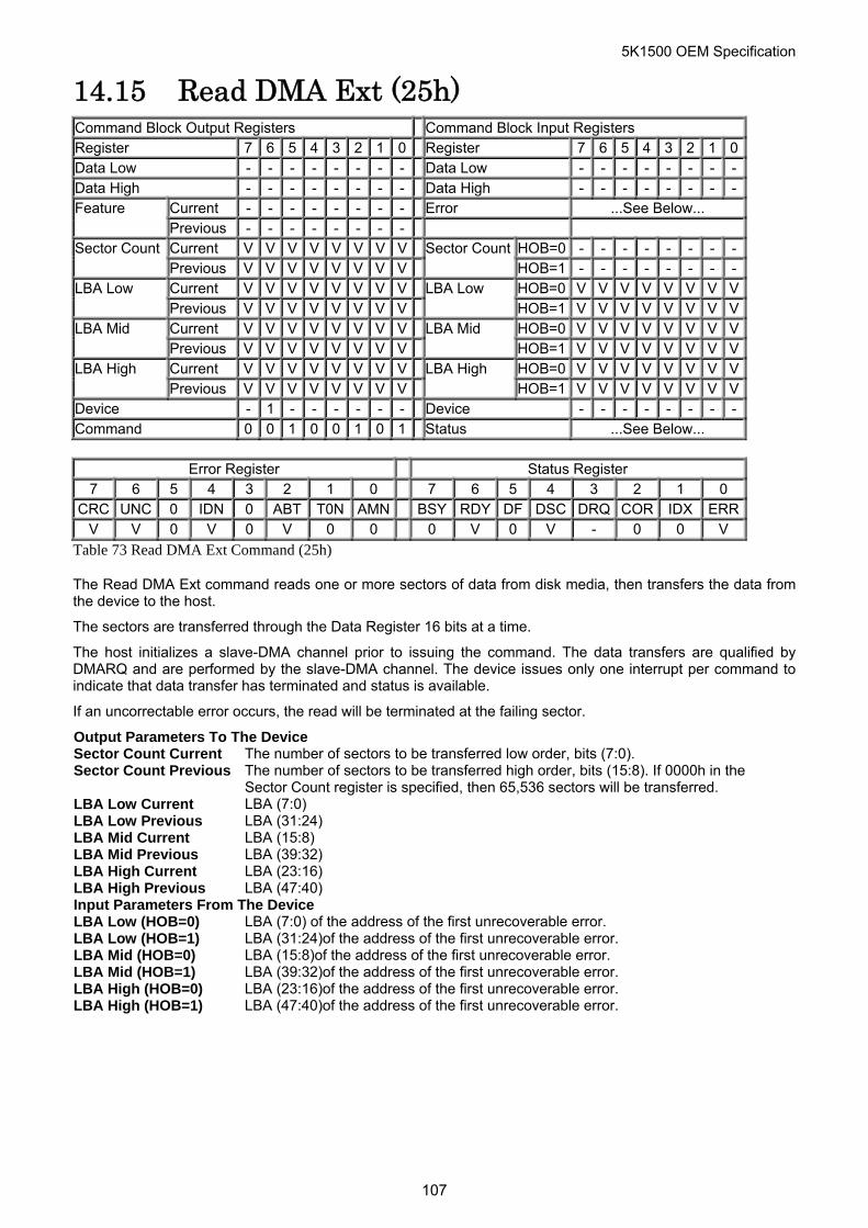
5K1500 OEM Specification
14.15 Read DMA Ext (25h) Command Block Output Registers Command Block Input Registers Register 7 6 5 4 3 2 1 0 Register 7 6 5 4 3 2 1 0Data Low - - - - - - - - Data Low - - - - - - - -Data High - - - - - - - - Data High - - - - - - - -
Current - - - - - - - - Error ...See Below... Feature Previous - - - - - - - - Current V V V V V V V V HOB=0 - - - - - - - -Sector Count Previous V V V V V V V V
Sector CountHOB=1 - - - - - - - -
Current V V V V V V V V HOB=0 V V V V V V V VLBA Low Previous V V V V V V V V
LBA Low HOB=1 V V V V V V V V
Current V V V V V V V V HOB=0 V V V V V V V VLBA Mid Previous V V V V V V V V
LBA Mid HOB=1 V V V V V V V V
Current V V V V V V V V HOB=0 V V V V V V V VLBA High Previous V V V V V V V V
LBA High HOB=1 V V V V V V V V
Device - 1 - - - - - - Device - - - - - - - -Command 0 0 1 0 0 1 0 1 Status ...See Below...
Error Register Status Register
7 6 5 4 3 2 1 0 7 6 5 4 3 2 1 0 CRC UNC 0 IDN 0 ABT T0N AMN BSY RDY DF DSC DRQ COR IDX ERR
V V 0 V 0 V 0 0 0 V 0 V - 0 0 V
Table 73 Read DMA Ext Command (25h)
The Read DMA Ext command reads one or more sectors of data from disk media, then transfers the data from the device to the host.
The sectors are transferred through the Data Register 16 bits at a time.
The host initializes a slave-DMA channel prior to issuing the command. The data transfers are qualified by DMARQ and are performed by the slave-DMA channel. The device issues only one interrupt per command to indicate that data transfer has terminated and status is available.
If an uncorrectable error occurs, the read will be terminated at the failing sector.
Output Parameters To The Device Sector Count Current The number of sectors to be transferred low order, bits (7:0). Sector Count Previous The number of sectors to be transferred high order, bits (15:8). If 0000h in the
Sector Count register is specified, then 65,536 sectors will be transferred. LBA Low Current LBA (7:0) LBA Low Previous LBA (31:24) LBA Mid Current LBA (15:8) LBA Mid Previous LBA (39:32) LBA High Current LBA (23:16) LBA High Previous LBA (47:40) Input Parameters From The Device LBA Low (HOB=0) LBA (7:0) of the address of the first unrecoverable error. LBA Low (HOB=1) LBA (31:24)of the address of the first unrecoverable error. LBA Mid (HOB=0) LBA (15:8)of the address of the first unrecoverable error. LBA Mid (HOB=1) LBA (39:32)of the address of the first unrecoverable error. LBA High (HOB=0) LBA (23:16)of the address of the first unrecoverable error. LBA High (HOB=1) LBA (47:40)of the address of the first unrecoverable error.
107
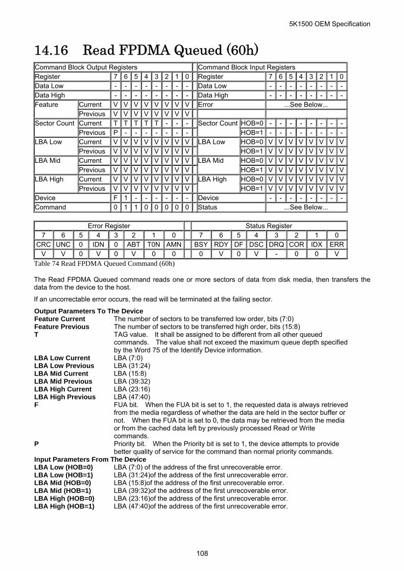
5K1500 OEM Specification
14.16 Read FPDMA Queued (60h) Command Block Output Registers Command Block Input Registers Register 7 6 5 4 3 2 1 0 Register 7 6 5 4 3 2 1 0Data Low - - - - - - - - Data Low - - - - - - - -Data High - - - - - - - - Data High - - - - - - - -
Current V V V V V V V V Error ...See Below... Feature Previous V V V V V V V V Current T T T T T - - - HOB=0 - - - - - - - -Sector Count Previous P - - - - - - -
Sector CountHOB=1 - - - - - - - -
Current V V V V V V V V HOB=0 V V V V V V V VLBA Low Previous V V V V V V V V
LBA Low HOB=1 V V V V V V V V
Current V V V V V V V V HOB=0 V V V V V V V VLBA Mid Previous V V V V V V V V
LBA Mid HOB=1 V V V V V V V V
Current V V V V V V V V HOB=0 V V V V V V V VLBA High Previous V V V V V V V V
LBA High HOB=1 V V V V V V V V
Device F 1 - - - - - - Device - - - - - - - -Command 0 1 1 0 0 0 0 0 Status ...See Below...
Error Register Status Register
7 6 5 4 3 2 1 0 7 6 5 4 3 2 1 0 CRC UNC 0 IDN 0 ABT T0N AMN BSY RDY DF DSC DRQ COR IDX ERR
V V 0 V 0 V 0 0 0 V 0 V - 0 0 V
Table 74 Read FPDMA Queued Command (60h)
The Read FPDMA Queued command reads one or more sectors of data from disk media, then transfers the data from the device to the host.
If an uncorrectable error occurs, the read will be terminated at the failing sector.
Output Parameters To The Device Feature Current The number of sectors to be transferred low order, bits (7:0) Feature Previous The number of sectors to be transferred high order, bits (15:8) T TAG value. It shall be assigned to be different from all other queued
commands. The value shall not exceed the maximum queue depth specified by the Word 75 of the Identify Device information.
LBA Low Current LBA (7:0) LBA Low Previous LBA (31:24) LBA Mid Current LBA (15:8) LBA Mid Previous LBA (39:32) LBA High Current LBA (23:16) LBA High Previous LBA (47:40) F FUA bit. When the FUA bit is set to 1, the requested data is always retrieved
from the media regardless of whether the data are held in the sector buffer or not. When the FUA bit is set to 0, the data may be retrieved from the media or from the cached data left by previously processed Read or Write commands.
P Priority bit. When the Priority bit is set to 1, the device attempts to provide better quality of service for the command than normal priority commands.
Input Parameters From The Device LBA Low (HOB=0) LBA (7:0) of the address of the first unrecoverable error. LBA Low (HOB=1) LBA (31:24)of the address of the first unrecoverable error. LBA Mid (HOB=0) LBA (15:8)of the address of the first unrecoverable error. LBA Mid (HOB=1) LBA (39:32)of the address of the first unrecoverable error. LBA High (HOB=0) LBA (23:16)of the address of the first unrecoverable error. LBA High (HOB=1) LBA (47:40)of the address of the first unrecoverable error.
108
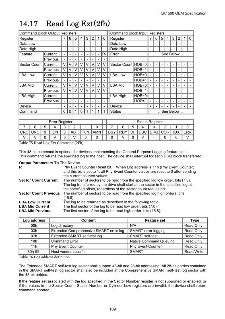
5K1500 OEM Specification
14.17 Read Log Ext(2fh) Command Block Output Registers Command Block Input Registers Register 7 6 5 4 3 2 1 0 Register 7 6 5 4 3 2 1 0Data Low - - - - - - - - Data Low - - - - - - - -Data High - - - - - - - - Data High - - - - - - - -
Current - - - - - - - R- Error ...See Below... Feature Previous - - - - - - - - Current V V V V V V V V HOB=0 - - - - - - - -Sector Count Previous V V V V V V V V
Sector CountHOB=1 - - - - - - - -
Current V V V V V V V V HOB=0 - - - - - - - -LBA Low Previous - - - - - - - -
LBA Low HOB=1 - - - - - - - -
Current V V V V V V V V HOB=0 - - - - - - - -LBA Mid Previous V V V V V V V V
LBA Mid HOB=1 - - - - - - - -
Current - - - - - - - - HOB=0 - - - - - - - -LBA High LBA High Previous - - - - - - - - HOB=1 - - - - - - - -
Device - - - - - - - - Device - - - - - - - -Command 0 0 1 0 1 1 1 1 Status ...See Below...
Error Register Status Register
7 6 5 4 3 2 1 0 7 6 5 4 3 2 1 0 CRC UNC 0 IDN 0 ABT T0N AMN BSY RDY DF DSC DRQ COR IDX ERR
V V 0 V 0 V 0 0 0 V 0 V - 0 0 V
Table 75 Read Log Ext Command (2Fh)
This 48-bit command is optional for devices implementing the General Purpose Logging feature set This command returns the specified log to the host. The device shall interrupt for each DRQ block transferred.
Output Parameters To The Device R Phy Event Counter Reset bit. When Log address is 11h (Phy Event Counter)
and this bit is set to 1, all Phy Event Counter values are reset to 0 after sending the current counter values.
Sector Count Current The number of sectors to be read from the specified log low order, bits (7:0). The log transferred by the drive shall start at the sector in the specified log at the specified offset, regardless of the sector count requested.
Sector Count Previous The number of sectors to be read from the specified log high orders, bits (15:8).
LBA Low Current The log to be returned as described in the following table. LBA Mid Current The first sector of the log to be read low order, bits (7:0). LBA Mid Previous The first sector of the log to be read high order, bits (15:8).
Log address Content Feature set Type 00h Log directory N/A Read Only 03h Extended Comprehensive SMART error log SMART error logging Read Only 07h Extended SMART self-test log SMART self-test Read Only 10h Command Error Native Command Queuing Read Only 11h Phy Event Counter Phy Event Counter Read Only
80h-9fh Host vendor specific SMART Read/Write
Table 76 Log address definition
The Extended SMART self-test log sector shall support 48-bit and 28-bit addressing. All 28-bit entries contained in the SMART self-test log sector shall also be included in the Comprehensive SMART self-test log sector with the 48-bit entries.
If the feature set associated with the log specified in the Sector Number register is not supported or enabled, or if the values in the Sector Count, Sector Number or Cylinder Low registers are invalid, the device shall return command aborted.
109
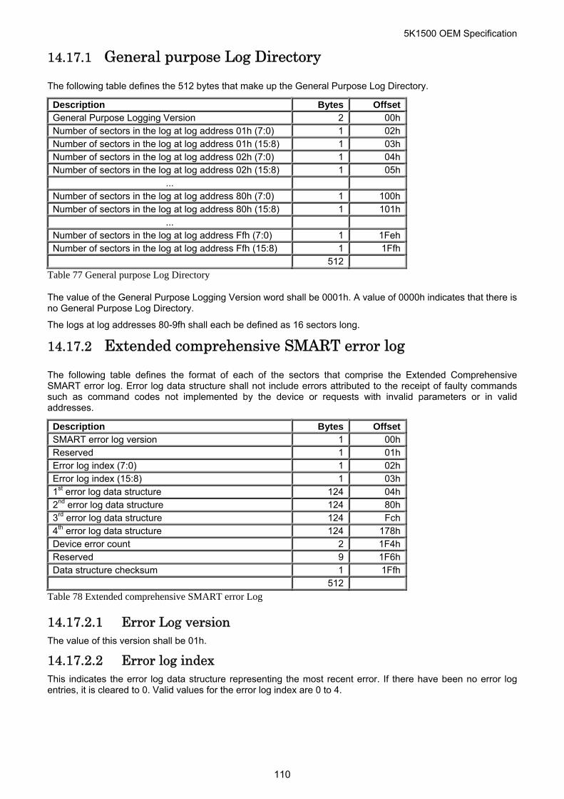
5K1500 OEM Specification
14.17.1 General purpose Log Directory
The following table defines the 512 bytes that make up the General Purpose Log Directory.
Description Bytes Offset General Purpose Logging Version 2 00h Number of sectors in the log at log address 01h (7:0) 1 02h Number of sectors in the log at log address 01h (15:8) 1 03h Number of sectors in the log at log address 02h (7:0) 1 04h Number of sectors in the log at log address 02h (15:8) 1 05h
... Number of sectors in the log at log address 80h (7:0) 1 100h Number of sectors in the log at log address 80h (15:8) 1 101h
... Number of sectors in the log at log address Ffh (7:0) 1 1Feh Number of sectors in the log at log address Ffh (15:8) 1 1Ffh 512
Table 77 General purpose Log Directory
The value of the General Purpose Logging Version word shall be 0001h. A value of 0000h indicates that there is no General Purpose Log Directory.
The logs at log addresses 80-9fh shall each be defined as 16 sectors long.
14.17.2 Extended comprehensive SMART error log
The following table defines the format of each of the sectors that comprise the Extended Comprehensive SMART error log. Error log data structure shall not include errors attributed to the receipt of faulty commands such as command codes not implemented by the device or requests with invalid parameters or in valid addresses.
Description Bytes Offset SMART error log version 1 00h Reserved 1 01h Error log index (7:0) 1 02h Error log index (15:8) 1 03h 1st error log data structure 124 04h 2nd error log data structure 124 80h 3rd error log data structure 124 Fch 4th error log data structure 124 178h Device error count 2 1F4h Reserved 9 1F6h Data structure checksum 1 1Ffh 512
Table 78 Extended comprehensive SMART error Log
14.17.2.1 Error Log version The value of this version shall be 01h.
14.17.2.2 Error log index This indicates the error log data structure representing the most recent error. If there have been no error log entries, it is cleared to 0. Valid values for the error log index are 0 to 4.
110
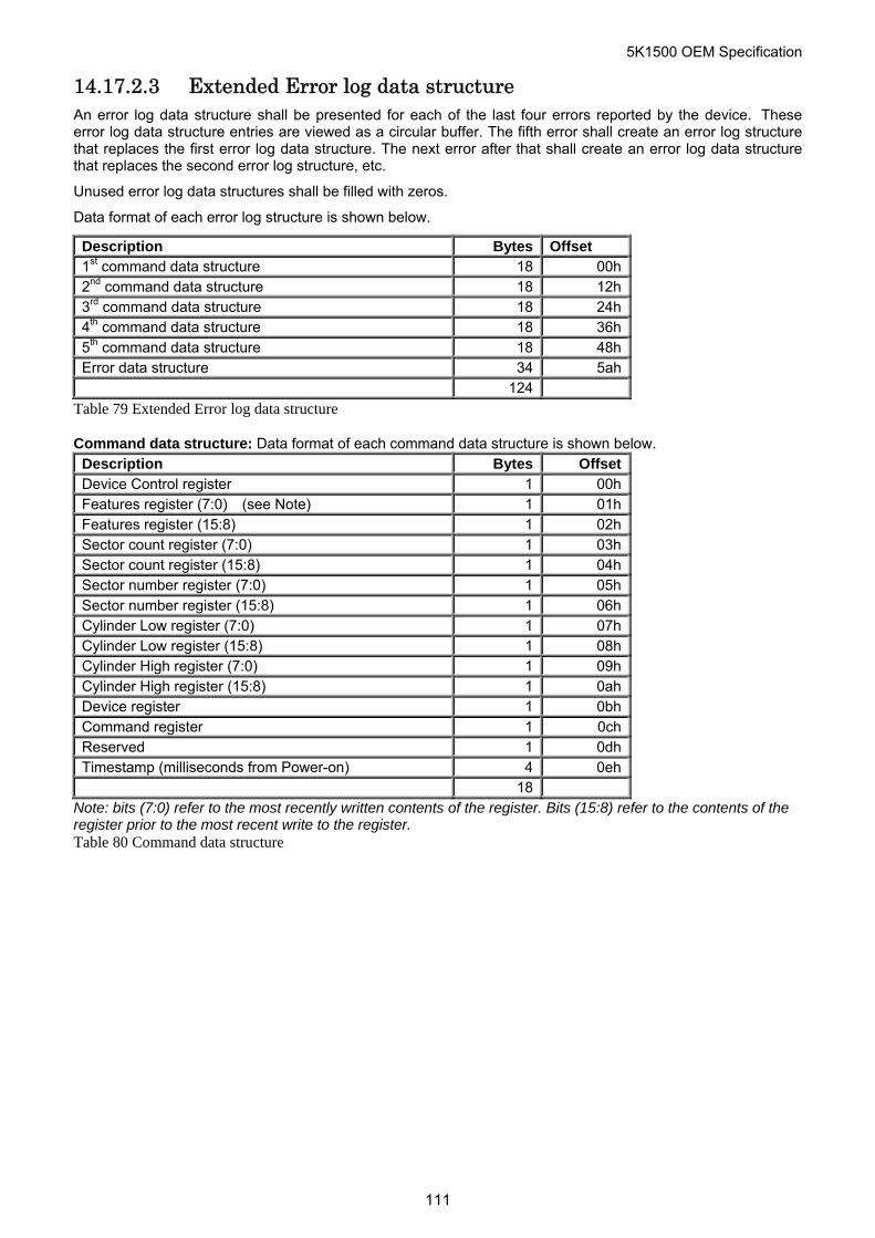
5K1500 OEM Specification
14.17.2.3 Extended Error log data structure An error log data structure shall be presented for each of the last four errors reported by the device. These error log data structure entries are viewed as a circular buffer. The fifth error shall create an error log structure that replaces the first error log data structure. The next error after that shall create an error log data structure that replaces the second error log structure, etc.
Unused error log data structures shall be filled with zeros.
Data format of each error log structure is shown below.
Description Bytes Offset 1st command data structure 18 00h 2nd command data structure 18 12h 3rd command data structure 18 24h 4th command data structure 18 36h 5th command data structure 18 48h Error data structure 34 5ah 124
Table 79 Extended Error log data structure
Command data structure: Data format of each command data structure is shown below. Description Bytes Offset Device Control register 1 00h Features register (7:0) (see Note) 1 01h Features register (15:8) 1 02h Sector count register (7:0) 1 03h Sector count register (15:8) 1 04h Sector number register (7:0) 1 05h Sector number register (15:8) 1 06h Cylinder Low register (7:0) 1 07h Cylinder Low register (15:8) 1 08h Cylinder High register (7:0) 1 09h Cylinder High register (15:8) 1 0ah Device register 1 0bh Command register 1 0ch Reserved 1 0dh Timestamp (milliseconds from Power-on) 4 0eh 18
Note: bits (7:0) refer to the most recently written contents of the register. Bits (15:8) refer to the contents of the register prior to the most recent write to the register. Table 80 Command data structure
111
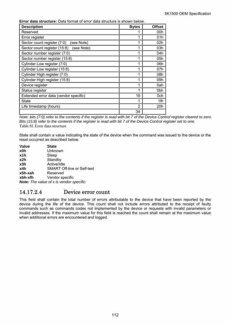
5K1500 OEM Specification
Error data structure: Data format of error data structure is shown below. Description Bytes Offset Reserved 1 00h Error register 1 01h Sector count register (7:0) (see Note) 1 02h Sector count register (15:8) (see Note) 1 03h Sector number register (7:0) 1 04h Sector number register (15:8) 1 05h Cylinder Low register (7:0) 1 06h Cylinder Low register (15:8) 1 07h Cylinder High register (7:0) 1 08h Cylinder High register (15:8) 1 09h Device register 1 0ah Status register 1 0bh Extended error data (vendor specific) 19 0ch State 1 1fh Life timestamp (hours) 2 20h 34
Note: bits (7:0) refer to the contents if the register is read with bit 7 of the Device Control register cleared to zero. Bits (15:8) refer to the contents if the register is read with bit 7 of the Device Control register set to one. Table 81 Error data structure
State shall contain a value indicating the state of the device when the command was issued to the device or the reset occurred as described below.
Value State x0h Unknown x1h Sleep x2h Standby x3h Active/Idle x4h SMART Off-line or Self-test x5h-xah Reserved xbh-xfh Vendor specific Note: The value of x is vendor specific.
14.17.2.4 Device error count This field shall contain the total number of errors attributable to the device that have been reported by the device during the life of the device. This count shall not include errors attributed to the receipt of faulty commands such as commands codes not implemented by the device or requests with invalid parameters or invalid addresses. If the maximum value for this field is reached the count shall remain at the maximum value when additional errors are encountered and logged.
112
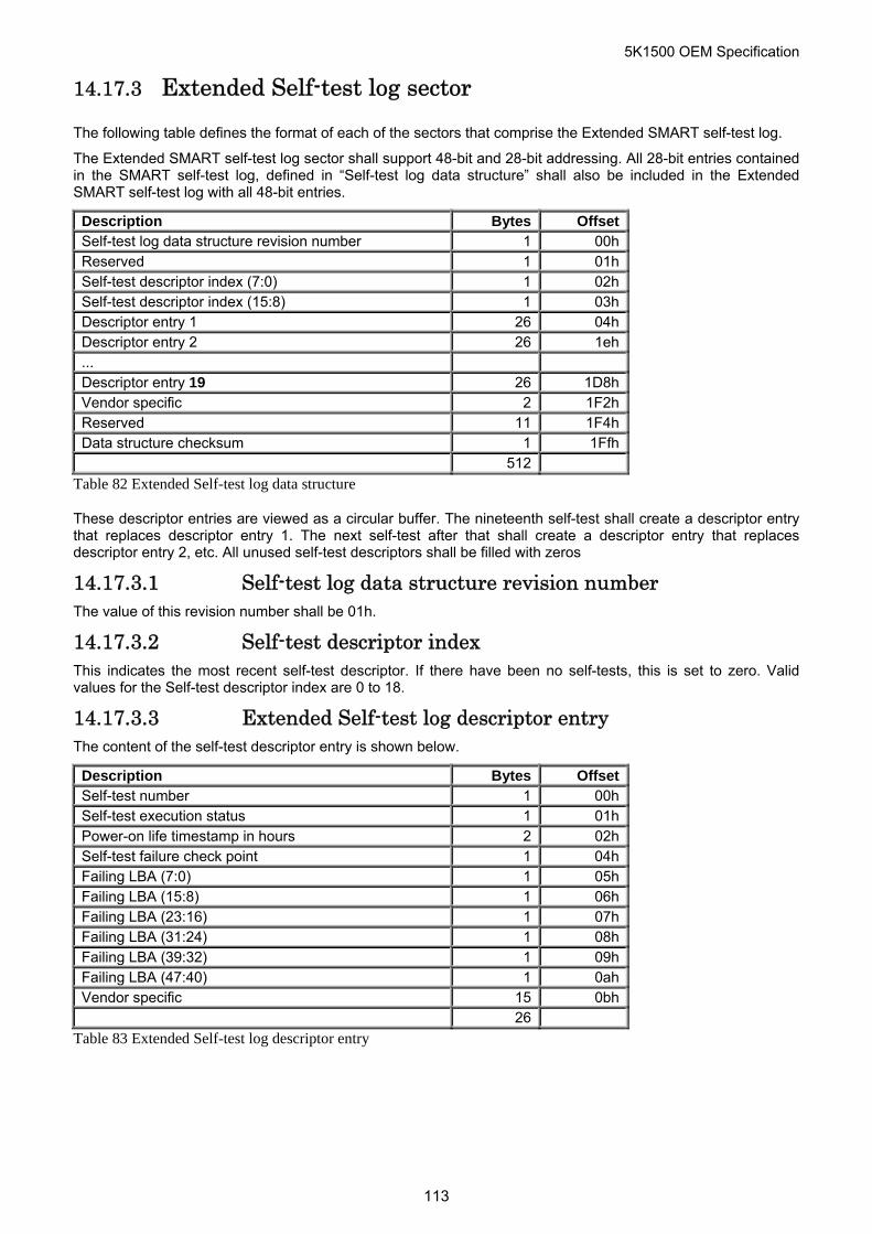
5K1500 OEM Specification
14.17.3 Extended Self-test log sector
The following table defines the format of each of the sectors that comprise the Extended SMART self-test log.
The Extended SMART self-test log sector shall support 48-bit and 28-bit addressing. All 28-bit entries contained in the SMART self-test log, defined in “Self-test log data structure” shall also be included in the Extended SMART self-test log with all 48-bit entries.
Description Bytes Offset Self-test log data structure revision number 1 00h Reserved 1 01h Self-test descriptor index (7:0) 1 02h Self-test descriptor index (15:8) 1 03h Descriptor entry 1 26 04h Descriptor entry 2 26 1eh ... Descriptor entry 19 26 1D8h Vendor specific 2 1F2h Reserved 11 1F4h Data structure checksum 1 1Ffh 512
Table 82 Extended Self-test log data structure
These descriptor entries are viewed as a circular buffer. The nineteenth self-test shall create a descriptor entry that replaces descriptor entry 1. The next self-test after that shall create a descriptor entry that replaces descriptor entry 2, etc. All unused self-test descriptors shall be filled with zeros
14.17.3.1 Self-test log data structure revision number
r index
or entry
The value of this revision number shall be 01h.
14.17.3.2 Self-test descriptoThis indicates the most recent self-test descriptor. If there have been no self-tests, this is set to zero. Valid values for the Self-test descriptor index are 0 to 18.
14.17.3.3 Extended Self-test log descriptThe content of the self-test descriptor entry is shown below.
Description Bytes Offset Self-test number 1 00h Self-test execution status 1 01h Power-on life timestamp in hours 2 02h Self-test failure check point 1 04h Failing LBA (7:0) 1 05h Failing LBA (15:8) 1 06h Failing LBA (23:16) 1 07h Failing LBA (31:24) 1 08h Failing LBA (39:32) 1 09h Failing LBA (47:40) 1 0ah Vendor specific 15 0bh 26
Table 83 Extended Self-test log descriptor entry
113

5K1500 OEM Specification
14.17.4 Command Error
The following table defines the format of the Command Error data structure.
Byte 7 6 5 4 3 2 1 0 0 NQ Rsv Rsv TAG 1 Reserved 2 Status 3 Error 4 LBA Low 5 LBA Mid 6 LBA High 7 Device 8 LBA Low Previous 9 LBA Mid Previous 10 LBA High Previous 11 Reserved 12 Sector Count 13 Sector Count Previous 14 – 255 Reserved 256 – 510 Vendor Unique 511 Data Structure Checksum
Table 84 Command Error information
The TAG field (Byte 0 bits 4-0) contains the tag number corresponding to a queued command, if the NQ bit is cleared.
The NQ field (Byte 0 bit 7) indicates whether the error condition was a result of a non-queued or not. If it is cleared, the error information corresponds to a queued command specified by the tag number indicated in the TAG field.
The bytes 1 to 13 correspond to the contents of Shadow Register Block when the error was reported.
The Data Structure Checksum (Byte 511) contains the 2’s complement of the sum of the first 511 bytes in the data structure. The sum of all 512 bytes of the data structure will be zero when the checksum is correct.
114
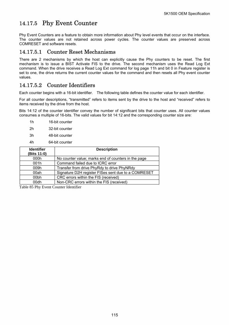
5K1500 OEM Specification
14.17.5 Phy Event Counter
Phy Event Counters are a feature to obtain more information about Phy level events that occur on the interface. The counter values are not retained across power cycles. The counter values are preserved across COMRESET and software resets.
14.17.5.1 Counter Reset Mechanisms There are 2 mechanisms by which the host can explicitly cause the Phy counters to be reset. The first mechanism is to issue a BIST Activate FIS to the drive. The second mechanism uses the Read Log Ext command. When the drive receives a Read Log Ext command for log page 11h and bit 0 in Feature register is set to one, the drive returns the current counter values for the command and then resets all Phy event counter values.
14.17.5.2 Counter Identifiers Each counter begins with a 16-bit identifier. The following table defines the counter value for each identifier.
For all counter descriptions, “transmitted” refers to items sent by the drive to the host and “received” refers to items received by the drive from the host.
Bits 14:12 of the counter identifier convey the number of significant bits that counter uses. All counter values consumes a multiple of 16-bits. The valid values for bit 14:12 and the corresponding counter size are:
1h 16-bit counter
2h 32-bit counter
3h 48-bit counter
4h 64-bit counter
Identifier (Bits 11:0)
Description
000h No counter value; marks end of counters in the page 001h Command failed due to ICRC error 009h Transfer from drive PhyRdy to drive PhyNRdy 00ah Signature D2H register FISes sent due to a COMRESET 00bh CRC errors within the FIS (received) 00dh Non-CRC errors within the FIS (received)
Table 85 Phy Event Counter Identifier
115
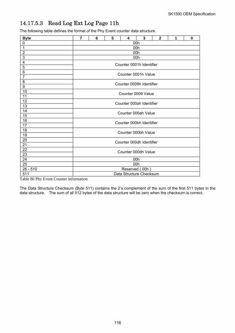
5K1500 OEM Specification
14.17.5.3 Read Log Ext Log Page 11h The following table defines the format of the Phy Event counter data structure.
Byte 7 6 5 4 3 2 1 0 0 00h 1 00h 2 00h 3 00h 4 5
Counter 0001h Identifier
6 7
Counter 0001h Value
8 9
Counter 0009h Identifier
10 11
Counter 0009 Value
12 13
Counter 000ah Identifier
14 15
Counter 000ah Value
16 17
Counter 000bh Identifier
18 19
Counter 000bh Value
20 21
Counter 000dh Identifier
22 23
Counter 000dh Value
24 00h 25 00h 26 - 510 Reserved ( 00h ) 511 Data Structure Checksum
Table 86 Phy Event Counter information
The Data Structure Checksum (Byte 511) contains the 2’s complement of the sum of the first 511 bytes in the data structure. The sum of all 512 bytes of the data structure will be zero when the checksum is correct.
116
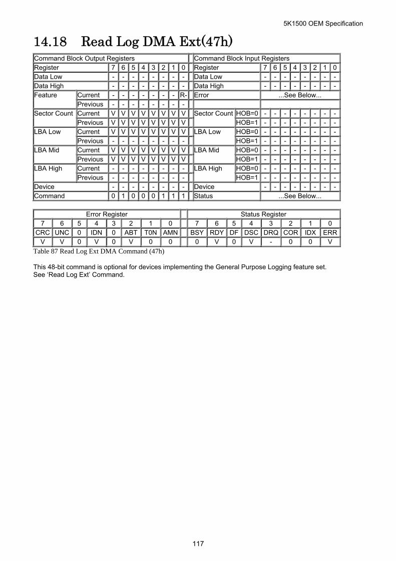
5K1500 OEM Specification
14.18 Read Log DMA Ext(47h) Command Block Output Registers Command Block Input Registers Register 7 6 5 4 3 2 1 0 Register 7 6 5 4 3 2 1 0Data Low - - - - - - - - Data Low - - - - - - - -Data High - - - - - - - - Data High - - - - - - - -
Current - - - - - - - R- Error ...See Below... Feature Previous - - - - - - - - Current V V V V V V V V HOB=0 - - - - - - - -Sector Count Previous V V V V V V V V
Sector CountHOB=1 - - - - - - - -
Current V V V V V V V V HOB=0 - - - - - - - -LBA Low Previous - - - - - - - -
LBA Low HOB=1 - - - - - - - -
Current V V V V V V V V HOB=0 - - - - - - - -LBA Mid Previous V V V V V V V V
LBA Mid HOB=1 - - - - - - - -
Current - - - - - - - - HOB=0 - - - - - - - -LBA High Previous - - - - - - - -
LBA High HOB=1 - - - - - - - -
Device - - - - - - - - Device - - - - - - - -Command 0 1 0 0 0 1 1 1 Status ...See Below...
Error Register Status Register
7 6 5 4 3 2 1 0 7 6 5 4 3 2 1 0 CRC UNC 0 IDN 0 ABT T0N AMN BSY RDY DF DSC DRQ COR IDX ERR
V V 0 V 0 V 0 0 0 V 0 V - 0 0 V
Table 87 Read Log Ext DMA Command (47h)
This 48-bit command is optional for devices implementing the General Purpose Logging feature set. See ‘Read Log Ext’ Command.
117

5K1500 OEM Specification
14.19 Read Multiple (C4h) Command Block Output Registers Command Block Input Registers Register 7 6 5 4 3 2 1 0 Register 7 6 5 4 3 2 1 0Data - - - - - - - - Data - - - - - - - -Feature - - - - - - - - Error ...See Below... Sector Count V V V V V V V V Sector Count V V V V V V V VLBA Low V V V V V V V V LBA Low V V V V V V V VLBA Mid V V V V V V V V LBA Mid V V V V V V V VLBA High V V V V V V V V LBA High V V V V V V V VDevice - L - - H H H H Device - - - - H H H HCommand 1 1 0 0 0 1 0 0 Status ...See Below...
Error Register Status Register
7 6 5 4 3 2 1 0 7 6 5 4 3 2 1 0 CRC UNC 0 IDN 0 ABT T0N AMN BSY RDY DF DSC DRQ COR IDX ERR
0 V 0 V 0 V 0 0 0 V 0 V - 0 0 V
Table 88 Read Multiple Command (C4h)
The Read Multiple command reads one or more sectors of data from disk media, then transfers the data from the device to the host.
The sectors are transferred through the Data Register 16 bits at a time. Command execution is identical to the Read Sectors command except that an interrupt is generated for each block (as defined by the Set Multiple command) instead of for each sector.
Output Parameters To The Device Sector Count The number of continuous sectors to be transferred. If zero is specified, then
256 sectors will be transferred. LBA Low The sector number of the first sector to be transferred. (L=0)
In LBA mode, this register contains LBA bits 0 - 7. (L=1) LBA High/Mid The cylinder number of the first sector to be transferred. (L=0)
In LBA mode, this register contains LBA bits 8 - 15 (Mid), 16 - 23 (High). (L=1) H The head number of the first sector to be transferred. (L=0)
In LBA mode, this register contains LBA bits 24 - 27. (L=1) Input Parameters From The Device Sector Count The number of requested sectors not transferred. This will be zero, unless an
unrecoverable error occurs. LBA Low The sector number of the last transferred sector. (L=0)
In LBA mode, this register contains current LBA bits 0 - 7. (L=1) LBA High/Mid The cylinder number of the last transferred sector. (L=0)
In LBA mode, this register contains current LBA bits 8-15 (Mid), 16-23 (High). (L=1)
H The head number of the last transferred sector. (L=0) LBA mode, this register contains current LBA bits 24 - 27. (L=1)
118
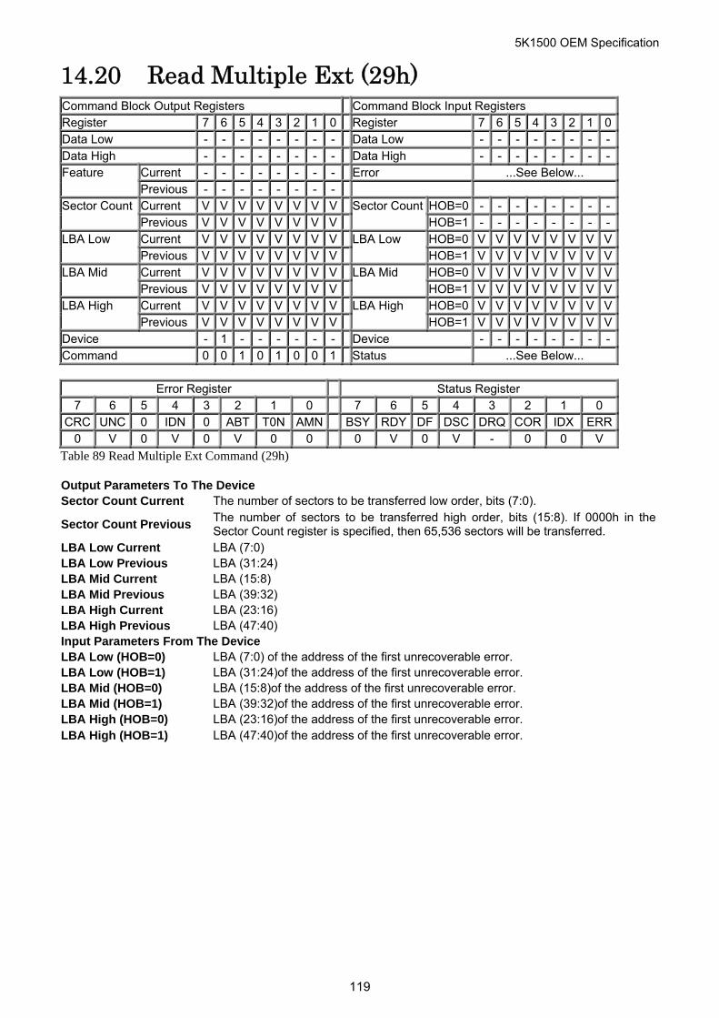
5K1500 OEM Specification
14.20 Read Multiple Ext (29h) Command Block Output Registers Command Block Input Registers Register 7 6 5 4 3 2 1 0 Register 7 6 5 4 3 2 1 0Data Low - - - - - - - - Data Low - - - - - - - -Data High - - - - - - - - Data High - - - - - - - -
Current - - - - - - - - Error ...See Below... Feature Previous - - - - - - - - Current V V V V V V V V HOB=0 - - - - - - - -Sector Count Previous V V V V V V V V
Sector CountHOB=1 - - - - - - - -
Current V V V V V V V V HOB=0 V V V V V V V VLBA Low Previous V V V V V V V V
LBA Low HOB=1 V V V V V V V V
Current V V V V V V V V HOB=0 V V V V V V V VLBA Mid Previous V V V V V V V V
LBA Mid HOB=1 V V V V V V V V
Current V V V V V V V V HOB=0 V V V V V V V VLBA High Previous V V V V V V V V
LBA High HOB=1 V V V V V V V V
Device - 1 - - - - - - Device - - - - - - - -Command 0 0 1 0 1 0 0 1 Status ...See Below...
Error Register Status Register
7 6 5 4 3 2 1 0 7 6 5 4 3 2 1 0 CRC UNC 0 IDN 0 ABT T0N AMN BSY RDY DF DSC DRQ COR IDX ERR
0 V 0 V 0 V 0 0 0 V 0 V - 0 0 V
Table 89 Read Multiple Ext Command (29h)
Output Parameters To The Device Sector Count Current The number of sectors to be transferred low order, bits (7:0).
Sector Count Previous The number of sectors to be transferred high order, bits (15:8). If 0000h in theSector Count register is specified, then 65,536 sectors will be transferred.
LBA Low Current LBA (7:0) LBA Low Previous LBA (31:24) LBA Mid Current LBA (15:8) LBA Mid Previous LBA (39:32) LBA High Current LBA (23:16) LBA High Previous LBA (47:40) Input Parameters From The Device LBA Low (HOB=0) LBA (7:0) of the address of the first unrecoverable error. LBA Low (HOB=1) LBA (31:24)of the address of the first unrecoverable error. LBA Mid (HOB=0) LBA (15:8)of the address of the first unrecoverable error. LBA Mid (HOB=1) LBA (39:32)of the address of the first unrecoverable error. LBA High (HOB=0) LBA (23:16)of the address of the first unrecoverable error. LBA High (HOB=1) LBA (47:40)of the address of the first unrecoverable error.
119
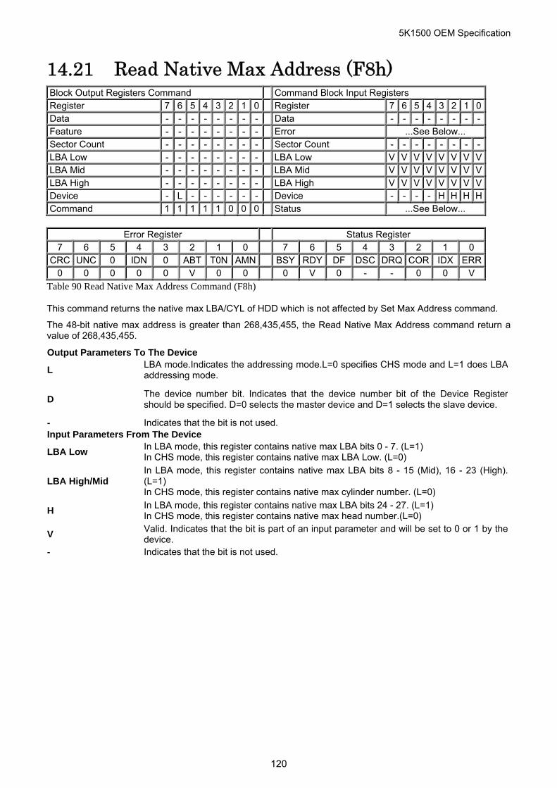
5K1500 OEM Specification
14.21 Read Native Max Address (F8h) Block Output Registers Command Command Block Input Registers Register 7 6 5 4 3 2 1 0 Register 7 6 5 4 3 2 1 0Data - - - - - - - - Data - - - - - - - -Feature - - - - - - - - Error ...See Below... Sector Count - - - - - - - - Sector Count - - - - - - - -LBA Low - - - - - - - - LBA Low V V V V V V V VLBA Mid - - - - - - - - LBA Mid V V V V V V V VLBA High - - - - - - - - LBA High V V V V V V V VDevice - L - - - - - - Device - - - - H H H HCommand 1 1 1 1 1 0 0 0 Status ...See Below...
Error Register Status Register
7 6 5 4 3 2 1 0 7 6 5 4 3 2 1 0 CRC UNC 0 IDN 0 ABT T0N AMN BSY RDY DF DSC DRQ COR IDX ERR
0 0 0 0 0 V 0 0 0 V 0 - - 0 0 V
Table 90 Read Native Max Address Command (F8h)
This command returns the native max LBA/CYL of HDD which is not affected by Set Max Address command.
The 48-bit native max address is greater than 268,435,455, the Read Native Max Address command return a value of 268,435,455.
Output Parameters To The Device
L LBA mode.Indicates the addressing mode.L=0 specifies CHS mode and L=1 does LBAaddressing mode.
D The device number bit. Indicates that the device number bit of the Device Registershould be specified. D=0 selects the master device and D=1 selects the slave device.
- Indicates that the bit is not used. Input Parameters From The Device
LBA Low In LBA mode, this register contains native max LBA bits 0 - 7. (L=1) In CHS mode, this register contains native max LBA Low. (L=0)
LBA High/Mid In LBA mode, this register contains native max LBA bits 8 - 15 (Mid), 16 - 23 (High). (L=1) In CHS mode, this register contains native max cylinder number. (L=0)
H In LBA mode, this register contains native max LBA bits 24 - 27. (L=1) In CHS mode, this register contains native max head number.(L=0)
V Valid. Indicates that the bit is part of an input parameter and will be set to 0 or 1 by thedevice.
- Indicates that the bit is not used.
120
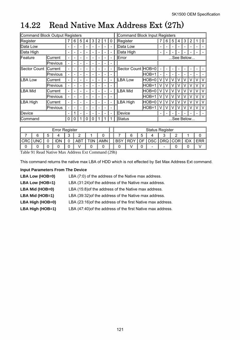
5K1500 OEM Specification
14.22 Read Native Max Address Ext (27h) Command Block Output Registers Command Block Input Registers Register 7 6 5 4 3 2 1 0 Register 7 6 5 4 3 2 1 0Data Low - - - - - - - - Data Low - - - - - - - -Data High - - - - - - - - Data High - - - - - - - -
Current - - - - - - - - Error ...See Below... Feature Previous - - - - - - - - Current - - - - - - - - HOB=0 - - - - - - - -Sector Count Previous - - - - - - - -
Sector CountHOB=1 - - - - - - - -
Current - - - - - - - - HOB=0 V V V V V V V VLBA Low LBA Low Previous - - - - - - - - HOB=1 V V V V V V V VCurrent - - - - - - - - HOB=0 V V V V V V V VLBA Mid Previous - - - - - - - -
LBA Mid HOB=1 V V V V V V V V
Current - - - - - - - - HOB=0 V V V V V V V VLBA High Previous
LBA High - - - - - - - - HOB=1 V V V V V V V V
Device - 1 - - - - - - Device - - - - - - - -Command 0 0 1 0 0 1 1 1 Status ...See Below...
Error Register Status Register
7 6 5 4 3 2 1 0 7 6 5 4 3 2 1 0 CRC UNC 0 IDN 0 ABT T0N AMN BSY RDY DF DSC DRQ COR IDX ERR
0 0 0 0 0 V 0 0 0 V 0 - - 0 0 V
Table 91 Read Native Max Address Ext Command (29h)
This command returns the native max LBA of HDD which is not effected by Set Max Address Ext command.
Input Parameters From The Device
LBA Low (HOB=0) LBA (7:0) of the address of the Native max address.
LBA Low (HOB=1) LBA (31:24)of the address of the Native max address.
LBA Mid (HOB=0) LBA (15:8)of the address of the Native max address.
LBA Mid (HOB=1) LBA (39:32)of the address of the Native max address.
LBA High (HOB=0) LBA (23:16)of the address of the first Native max address.
LBA High (HOB=1) LBA (47:40)of the address of the first Native max address.
121
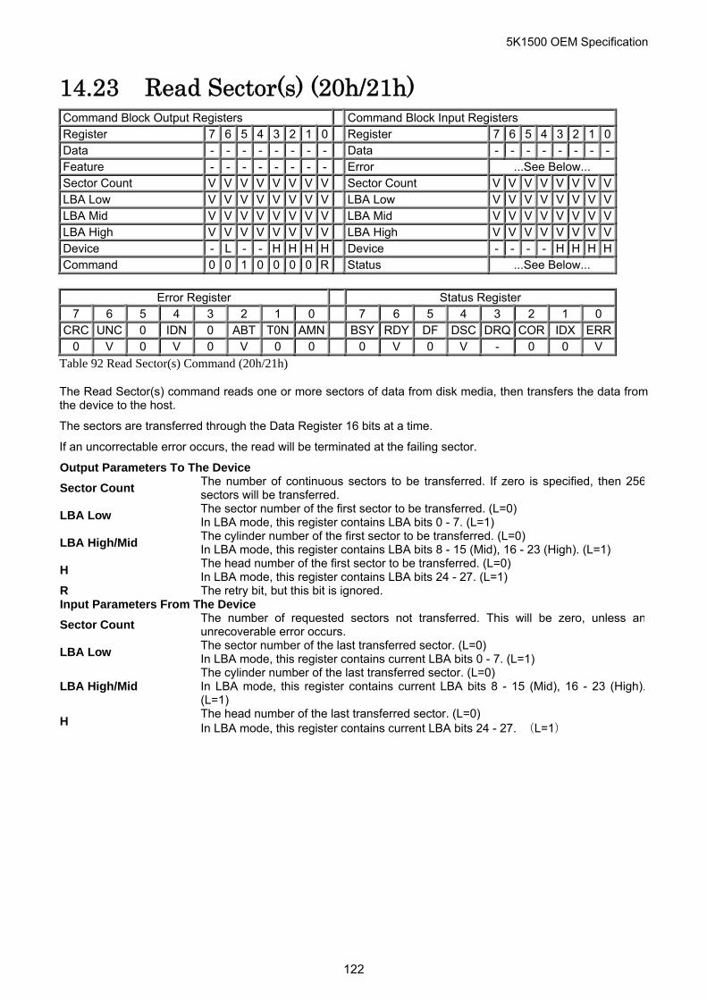
5K1500 OEM Specification
14.23 Read Sector(s) (20h/21h) Command Block Output Registers Command Block Input Registers Register 7 6 5 4 3 2 1 0 Register 7 6 5 4 3 2 1 0Data - - - - - - - - Data - - - - - - - -Feature - - - - - - - - Error ...See Below... Sector Count V V V V V V V V Sector Count V V V V V V V VLBA Low V V V V V V V V LBA Low V V V V V V V VLBA Mid V V V V V V V V LBA Mid V V V V V V V VLBA High V V V V V V V V LBA High V V V V V V V VDevice - L - - H H H H Device - - - - H H H HCommand 0 0 1 0 0 0 0 R Status ...See Below...
Error Register Status Register
7 6 5 4 3 2 1 0 7 6 5 4 3 2 1 0 CRC UNC 0 IDN 0 ABT T0N AMN BSY RDY DF DSC DRQ COR IDX ERR
0 V 0 V 0 V 0 0 0 V 0 V - 0 0 V
Table 92 Read Sector(s) Command (20h/21h)
The Read Sector(s) command reads one or more sectors of data from disk media, then transfers the data from the device to the host.
The sectors are transferred through the Data Register 16 bits at a time.
If an uncorrectable error occurs, the read will be terminated at the failing sector.
Output Parameters To The Device
Sector Count The number of continuous sectors to be transferred. If zero is specified, then 256sectors will be transferred.
LBA Low The sector number of the first sector to be transferred. (L=0) In LBA mode, this register contains LBA bits 0 - 7. (L=1)
LBA High/Mid The cylinder number of the first sector to be transferred. (L=0) In LBA mode, this register contains LBA bits 8 - 15 (Mid), 16 - 23 (High). (L=1)
H The head number of the first sector to be transferred. (L=0) In LBA mode, this register contains LBA bits 24 - 27. (L=1)
R The retry bit, but this bit is ignored. Input Parameters From The Device
Sector Count The number of requested sectors not transferred. This will be zero, unless anunrecoverable error occurs.
LBA Low The sector number of the last transferred sector. (L=0) In LBA mode, this register contains current LBA bits 0 - 7. (L=1)
LBA High/Mid The cylinder number of the last transferred sector. (L=0) In LBA mode, this register contains current LBA bits 8 - 15 (Mid), 16 - 23 (High).(L=1)
H The head number of the last transferred sector. (L=0) In LBA mode, this register contains current LBA bits 24 - 27. (L=1)
122
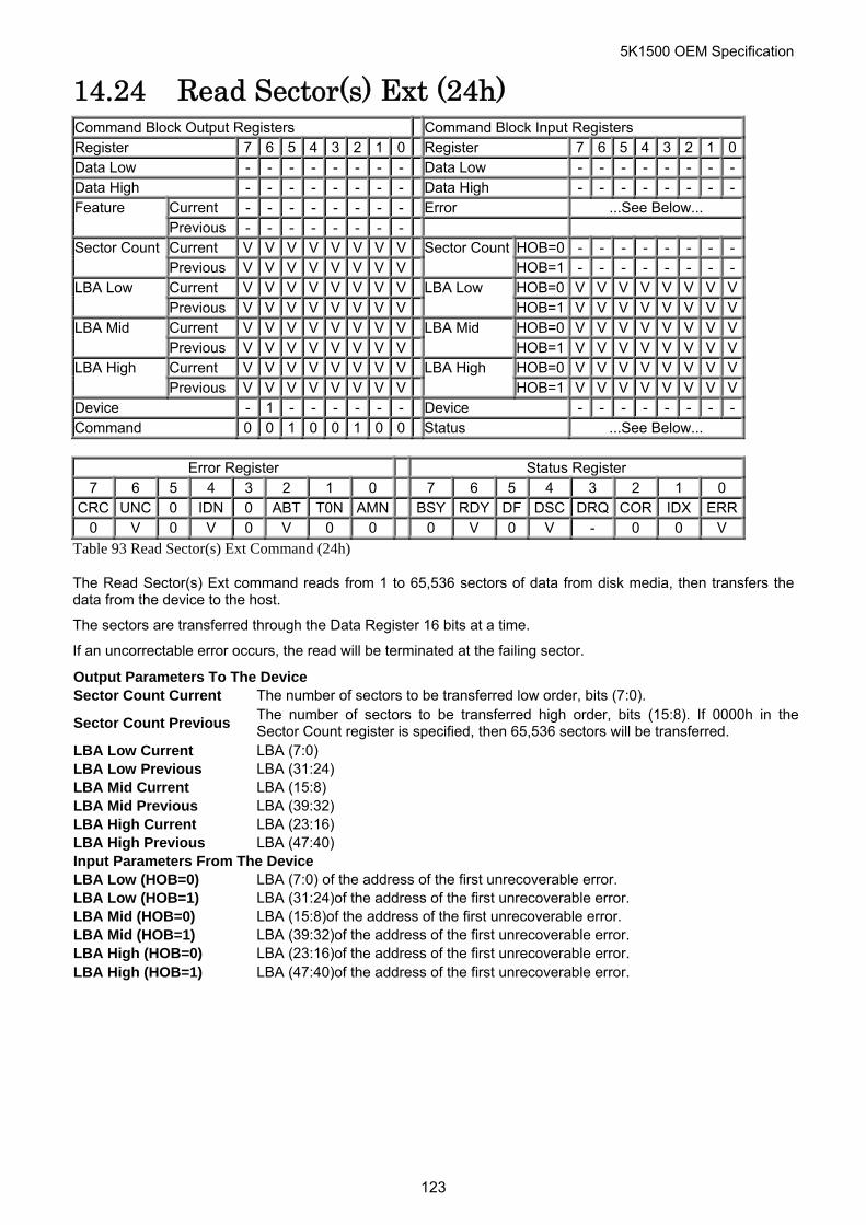
5K1500 OEM Specification
14.24 Read Sector(s) Ext (24h) Command Block Output Registers Command Block Input Registers Register 7 6 5 4 3 2 1 0 Register 7 6 5 4 3 2 1 0Data Low - - - - - - - - Data Low - - - - - - - -Data High - - - - - - - - Data High - - - - - - - -
Current - - - - - - - - Error ...See Below... Feature Previous - - - - - - - - Current V V V V V V V V HOB=0 - - - - - - - -Sector Count Previous V V V V V V V V
Sector CountHOB=1 - - - - - - - -
Current V V V V V V V V HOB=0 V V V V V V V VLBA Low Previous V V V V V V V V
LBA Low HOB=1 V V V V V V V V
Current V V V V V V V V HOB=0 V V V V V V V VLBA Mid Previous V V V V V V V V
LBA Mid HOB=1 V V V V V V V V
Current V V V V V V V V HOB=0 V V V V V V V VLBA High Previous V V V V V V V V
LBA High HOB=1 V V V V V V V V
Device - 1 - - - - - - Device - - - - - - - -Command 0 0 1 0 0 1 0 0 Status ...See Below...
Error Register Status Register
7 6 5 4 3 2 1 0 7 6 5 4 3 2 1 0 CRC UNC 0 IDN 0 ABT T0N AMN BSY RDY DF DSC DRQ COR IDX ERR
0 V 0 V 0 V 0 0 0 V 0 V - 0 0 V
Table 93 Read Sector(s) Ext Command (24h)
The Read Sector(s) Ext command reads from 1 to 65,536 sectors of data from disk media, then transfers the data from the device to the host.
The sectors are transferred through the Data Register 16 bits at a time.
If an uncorrectable error occurs, the read will be terminated at the failing sector.
Output Parameters To The Device Sector Count Current The number of sectors to be transferred low order, bits (7:0).
Sector Count Previous The number of sectors to be transferred high order, bits (15:8). If 0000h in theSector Count register is specified, then 65,536 sectors will be transferred.
LBA Low Current LBA (7:0) LBA Low Previous LBA (31:24) LBA Mid Current LBA (15:8) LBA Mid Previous LBA (39:32) LBA High Current LBA (23:16) LBA High Previous LBA (47:40) Input Parameters From The Device LBA Low (HOB=0) LBA (7:0) of the address of the first unrecoverable error. LBA Low (HOB=1) LBA (31:24)of the address of the first unrecoverable error. LBA Mid (HOB=0) LBA (15:8)of the address of the first unrecoverable error. LBA Mid (HOB=1) LBA (39:32)of the address of the first unrecoverable error. LBA High (HOB=0) LBA (23:16)of the address of the first unrecoverable error. LBA High (HOB=1) LBA (47:40)of the address of the first unrecoverable error.
123
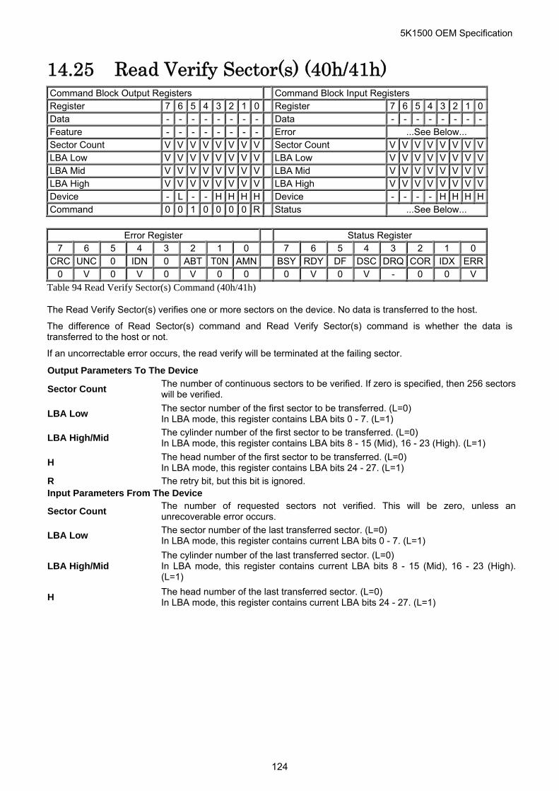
5K1500 OEM Specification
14.25 Read Verify Sector(s) (40h/41h) Command Block Output Registers Command Block Input Registers Register 7 6 5 4 3 2 1 0 Register 7 6 5 4 3 2 1 0Data - - - - - - - - Data - - - - - - - -Feature - - - - - - - - Error ...See Below... Sector Count V V V V V V V V Sector Count V V V V V V V VLBA Low V V V V V V V V LBA Low V V V V V V V VLBA Mid V V V V V V V V LBA Mid V V V V V V V VLBA High V V V V V V V V LBA High V V V V V V V VDevice - L - - H H H H Device - - - - H H H HCommand 0 0 1 0 0 0 0 R Status ...See Below...
Error Register Status Register
7 6 5 4 3 2 1 0 7 6 5 4 3 2 1 0 CRC UNC 0 IDN 0 ABT T0N AMN BSY RDY DF DSC DRQ COR IDX ERR
0 V 0 V 0 V 0 0 0 V 0 V - 0 0 V
Table 94 Read Verify Sector(s) Command (40h/41h)
The Read Verify Sector(s) verifies one or more sectors on the device. No data is transferred to the host.
The difference of Read Sector(s) command and Read Verify Sector(s) command is whether the data is transferred to the host or not.
If an uncorrectable error occurs, the read verify will be terminated at the failing sector.
Output Parameters To The Device
Sector Count The number of continuous sectors to be verified. If zero is specified, then 256 sectors will be verified.
LBA Low The sector number of the first sector to be transferred. (L=0) In LBA mode, this register contains LBA bits 0 - 7. (L=1)
LBA High/Mid The cylinder number of the first sector to be transferred. (L=0) In LBA mode, this register contains LBA bits 8 - 15 (Mid), 16 - 23 (High). (L=1)
H The head number of the first sector to be transferred. (L=0) In LBA mode, this register contains LBA bits 24 - 27. (L=1)
R The retry bit, but this bit is ignored. Input Parameters From The Device
Sector Count The number of requested sectors not verified. This will be zero, unless an unrecoverable error occurs.
LBA Low The sector number of the last transferred sector. (L=0) In LBA mode, this register contains current LBA bits 0 - 7. (L=1)
LBA High/Mid The cylinder number of the last transferred sector. (L=0) In LBA mode, this register contains current LBA bits 8 - 15 (Mid), 16 - 23 (High). (L=1)
H The head number of the last transferred sector. (L=0) In LBA mode, this register contains current LBA bits 24 - 27. (L=1)
124
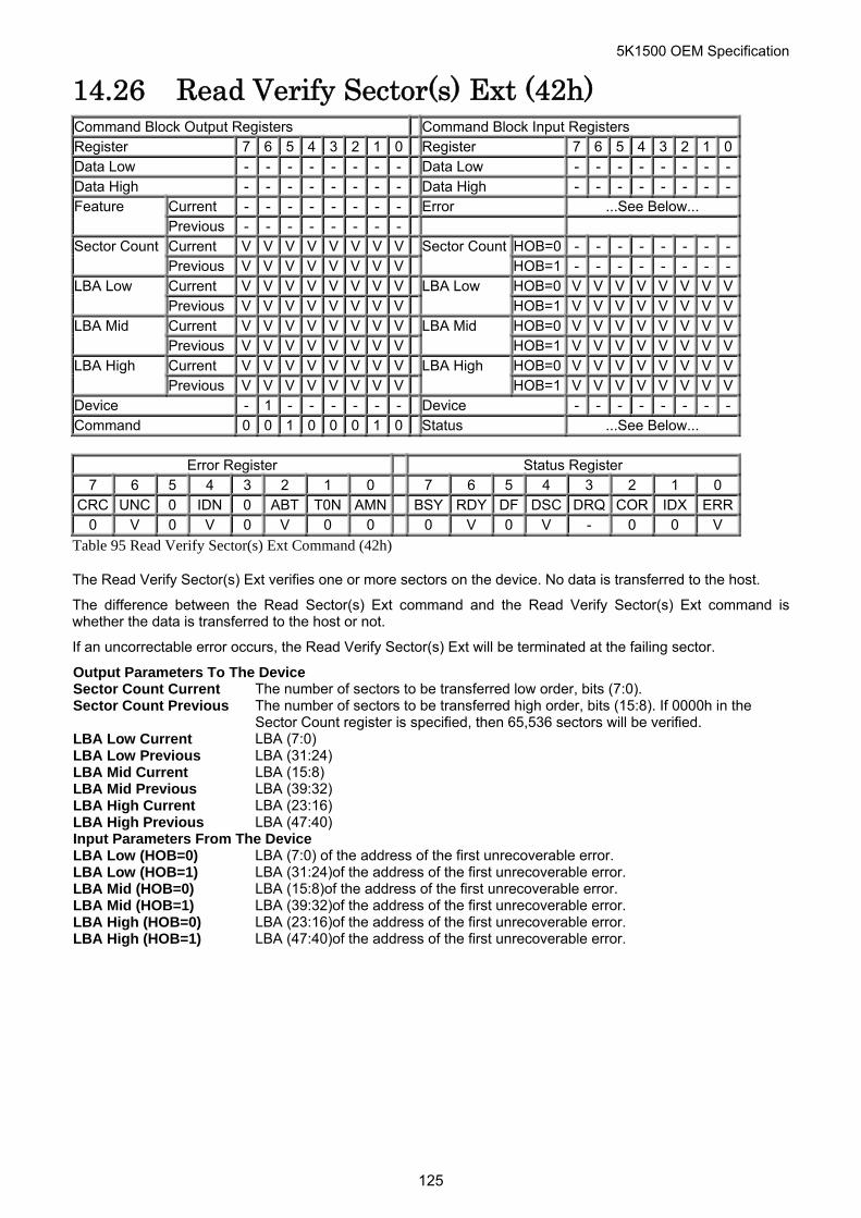
5K1500 OEM Specification
14.26 Read Verify Sector(s) Ext (42h) Command Block Output Registers Command Block Input Registers Register 7 6 5 4 3 2 1 0 Register 7 6 5 4 3 2 1 0Data Low - - - - - - - - Data Low - - - - - - - -Data High - - - - - - - - Data High - - - - - - - -
Current - - - - - - - - Error ...See Below... Feature Previous - - - - - - - - Current V V V V V V V V HOB=0 - - - - - - - -Sector Count Previous V V V V V V V V
Sector CountHOB=1 - - - - - - - -
Current V V V V V V V V HOB=0 V V V V V V V VLBA Low Previous V V V V V V V V
LBA Low HOB=1 V V V V V V V V
Current V V V V V V V V HOB=0 V V V V V V V VLBA Mid Previous V V V V V V V V
LBA Mid HOB=1 V V V V V V V V
Current V V V V V V V V HOB=0 V V V V V V V VLBA High Previous V V V V V V V V
LBA High HOB=1 V V V V V V V V
Device - 1 - - - - - - Device - - - - - - - -Command 0 0 1 0 0 0 1 0 Status ...See Below...
Error Register Status Register
7 6 5 4 3 2 1 0 7 6 5 4 3 2 1 0 CRC UNC 0 IDN 0 ABT T0N AMN BSY RDY DF DSC DRQ COR IDX ERR
0 V 0 V 0 V 0 0 0 V 0 V - 0 0 V
Table 95 Read Verify Sector(s) Ext Command (42h)
The Read Verify Sector(s) Ext verifies one or more sectors on the device. No data is transferred to the host.
The difference between the Read Sector(s) Ext command and the Read Verify Sector(s) Ext command is whether the data is transferred to the host or not.
If an uncorrectable error occurs, the Read Verify Sector(s) Ext will be terminated at the failing sector.
Output Parameters To The Device Sector Count Current The number of sectors to be transferred low order, bits (7:0). Sector Count Previous The number of sectors to be transferred high order, bits (15:8). If 0000h in the
Sector Count register is specified, then 65,536 sectors will be verified. LBA Low Current LBA (7:0) LBA Low Previous LBA (31:24) LBA Mid Current LBA (15:8) LBA Mid Previous LBA (39:32) LBA High Current LBA (23:16) LBA High Previous LBA (47:40) Input Parameters From The Device LBA Low (HOB=0) LBA (7:0) of the address of the first unrecoverable error. LBA Low (HOB=1) LBA (31:24)of the address of the first unrecoverable error. LBA Mid (HOB=0) LBA (15:8)of the address of the first unrecoverable error. LBA Mid (HOB=1) LBA (39:32)of the address of the first unrecoverable error. LBA High (HOB=0) LBA (23:16)of the address of the first unrecoverable error. LBA High (HOB=1) LBA (47:40)of the address of the first unrecoverable error.
125
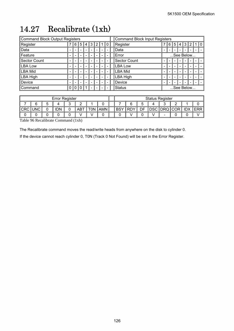
5K1500 OEM Specification
14.27 Recalibrate (1xh) Command Block Output Registers Command Block Input Registers Register 7 6 5 4 3 2 1 0 Register 7 6 5 4 3 2 1 0Data - - - - - - - - Data - - - - - - - -Feature - - - - - - - - Error ...See Below... Sector Count - - - - - - - - Sector Count - - - - - - - -LBA Low - - - - - - - - LBA Low - - - - - - - -LBA Mid - - - - - - - - LBA Mid - - - - - - - -LBA High - - - - - - - - LBA High - - - - - - - -Device - - - - - - - - Device - - - - - - - -Command 0 0 0 1 - - - - Status ...See Below...
Error Register Status Register
7 6 5 4 3 2 1 0 7 6 5 4 3 2 1 0 CRC UNC 0 IDN 0 ABT T0N AMN BSY RDY DF DSC DRQ COR IDX ERR
0 0 0 0 0 V V 0 0 V 0 V - 0 0 V
Table 96 Recalibrate Command (1xh)
The Recalibrate command moves the read/write heads from anywhere on the disk to cylinder 0.
If the device cannot reach cylinder 0, T0N (Track 0 Not Found) will be set in the Error Register.
126
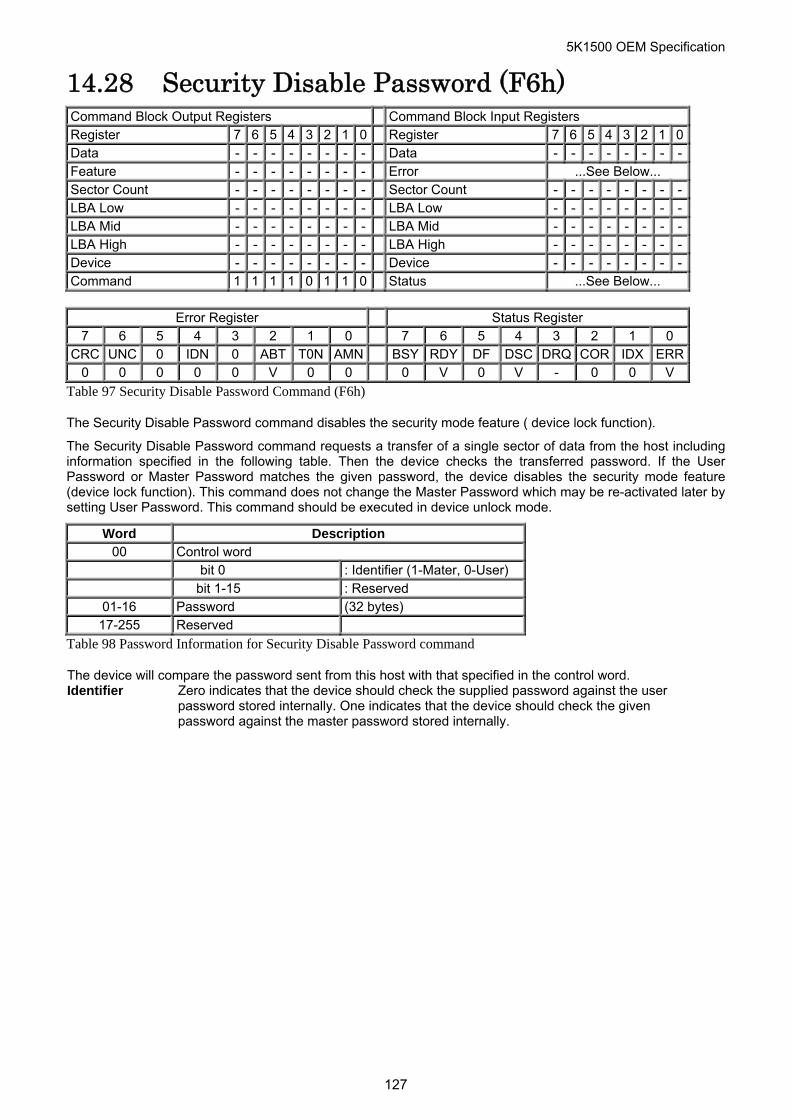
5K1500 OEM Specification
14.28 Security Disable Password (F6h) Command Block Output Registers Command Block Input Registers Register 7 6 5 4 3 2 1 0 Register 7 6 5 4 3 2 1 0Data - - - - - - - - Data - - - - - - - -Feature - - - - - - - - Error ...See Below... Sector Count - - - - - - - - Sector Count - - - - - - - -LBA Low - - - - - - - - LBA Low - - - - - - - -LBA Mid - - - - - - - - LBA Mid - - - - - - - -LBA High - - - - - - - - LBA High - - - - - - - -Device - - - - - - - - Device - - - - - - - -Command 1 1 1 1 0 1 1 0 Status ...See Below...
Error Register Status Register
7 6 5 4 3 2 1 0 7 6 5 4 3 2 1 0 CRC UNC 0 IDN 0 ABT T0N AMN BSY RDY DF DSC DRQ COR IDX ERR
0 0 0 0 0 V 0 0 0 V 0 V - 0 0 V
Table 97 Security Disable Password Command (F6h)
The Security Disable Password command disables the security mode feature ( device lock function).
The Security Disable Password command requests a transfer of a single sector of data from the host including information specified in the following table. Then the device checks the transferred password. If the User Password or Master Password matches the given password, the device disables the security mode feature (device lock function). This command does not change the Master Password which may be re-activated later by setting User Password. This command should be executed in device unlock mode.
Word Description 00 Control word bit 0 : Identifier (1-Mater, 0-User) bit 1-15 : Reserved
01-16 Password (32 bytes) 17-255 Reserved
Table 98 Password Information for Security Disable Password command
The device will compare the password sent from this host with that specified in the control word. Identifier Zero indicates that the device should check the supplied password against the user
password stored internally. One indicates that the device should check the given password against the master password stored internally.
127

5K1500 OEM Specification
14.29 Security Erase Prepare (F3h) Command Block Output Registers Command Block Input Registers Register 7 6 5 4 3 2 1 0 Register 7 6 5 4 3 2 1 0Data - - - - - - - - Data - - - - - - - -Feature - - - - - - - - Error ...See Below... Sector Count - - - - - - - - Sector Count - - - - - - - -LBA Low - - - - - - - - LBA Low - - - - - - - -LBA Mid - - - - - - - - LBA Mid - - - - - - - -LBA High - - - - - - - - LBA High - - - - - - - -Device - - - - - - - - Device - - - - - - - -Command 1 1 1 1 0 0 1 1 Status ...See Below...
Error Register Status Register
7 6 5 4 3 2 1 0 7 6 5 4 3 2 1 0 CRC UNC 0 IDN 0 ABT T0N AMN BSY RDY DF DSC DRQ COR IDX ERR
0 0 0 0 0 V 0 0 0 V 0 V - 0 0 V
Table 99 Security Erase Prepare Command (F3h)
The Security Erase Prepare Command must be issued immediately before the Security Erase Unit Command to enable device erasing and unlocking.
The Security Erase Prepare Command must be issued immediately before the Format Unit Command. This command is to prevent accidental erasure of the device.
This command does not request to transfer data.
128
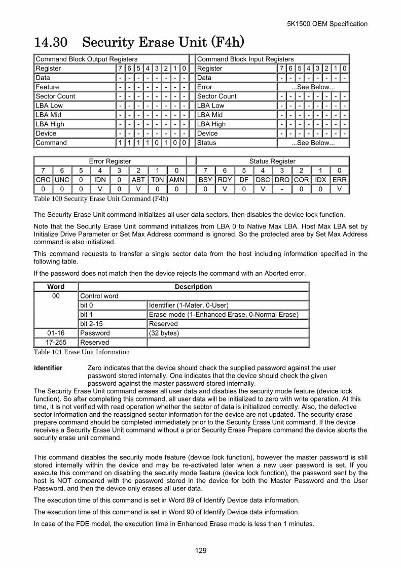
5K1500 OEM Specification
14.30 Security Erase Unit (F4h) Command Block Output Registers Command Block Input Registers Register 7 6 5 4 3 2 1 0 Register 7 6 5 4 3 2 1 0Data - - - - - - - - Data - - - - - - - -Feature - - - - - - - - Error ...See Below... Sector Count - - - - - - - - Sector Count - - - - - - - -LBA Low - - - - - - - - LBA Low - - - - - - - -LBA Mid - - - - - - - - LBA Mid - - - - - - - -LBA High - - - - - - - - LBA High - - - - - - - -Device - - - - - - - - Device - - - - - - - -Command 1 1 1 1 0 1 0 0 Status ...See Below...
Error Register Status Register
7 6 5 4 3 2 1 0 7 6 5 4 3 2 1 0 CRC UNC 0 IDN 0 ABT T0N AMN BSY RDY DF DSC DRQ COR IDX ERR
0 0 0 V 0 V 0 0 0 V 0 V - 0 0 V
Table 100 Security Erase Unit Command (F4h)
The Security Erase Unit command initializes all user data sectors, then disables the device lock function.
Note that the Security Erase Unit command initializes from LBA 0 to Native Max LBA. Host Max LBA set by Initialize Drive Parameter or Set Max Address command is ignored. So the protected area by Set Max Address command is also initialized.
This command requests to transfer a single sector data from the host including information specified in the following table.
If the password does not match then the device rejects the command with an Aborted error.
Word Description Control word bit 0 Identifier (1-Mater, 0-User) bit 1 Erase mode (1-Enhanced Erase, 0-Normal Erase)
00
bit 2-15 Reserved 01-16 Password (32 bytes) 17-255 Reserved
Table 101 Erase Unit Information
Identifier Zero indicates that the device should check the supplied password against the user password stored internally. One indicates that the device should check the given password against the master password stored internally.
The Security Erase Unit command erases all user data and disables the security mode feature (device lock function). So after completing this command, all user data will be initialized to zero with write operation. At this time, it is not verified with read operation whether the sector of data is initialized correctly. Also, the defective sector information and the reassigned sector information for the device are not updated. The security erase prepare command should be completed immediately prior to the Security Erase Unit command. If the device receives a Security Erase Unit command without a prior Security Erase Prepare command the device aborts the security erase unit command.
This command disables the security mode feature (device lock function), however the master password is still stored internally within the device and may be re-activated later when a new user password is set. If you execute this command on disabling the security mode feature (device lock function), the password sent by the host is NOT compared with the password stored in the device for both the Master Password and the User Password, and then the device only erases all user data.
The execution time of this command is set in Word 89 of Identify Device data information.
The execution time of this command is set in Word 90 of Identify Device data information.
In case of the FDE model, the execution time in Enhanced Erase mode is less than 1 minutes.
129
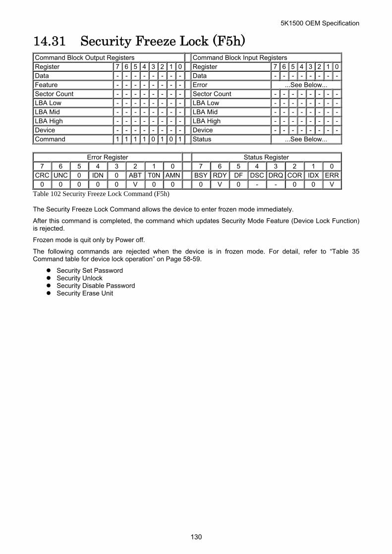
5K1500 OEM Specification
14.31 Security Freeze Lock (F5h) Command Block Output Registers Command Block Input Registers Register 7 6 5 4 3 2 1 0 Register 7 6 5 4 3 2 1 0Data - - - - - - - - Data - - - - - - - -Feature - - - - - - - - Error ...See Below... Sector Count - - - - - - - - Sector Count - - - - - - - -LBA Low - - - - - - - - LBA Low - - - - - - - -LBA Mid - - - - - - - - LBA Mid - - - - - - - -LBA High - - - - - - - - LBA High - - - - - - - -Device - - - - - - - - Device - - - - - - - -Command 1 1 1 1 0 1 0 1 Status ...See Below...
Error Register Status Register
7 6 5 4 3 2 1 0 7 6 5 4 3 2 1 0 CRC UNC 0 IDN 0 ABT T0N AMN BSY RDY DF DSC DRQ COR IDX ERR
0 0 0 0 0 V 0 0 0 V 0 - - 0 0 V
Table 102 Security Freeze Lock Command (F5h)
The Security Freeze Lock Command allows the device to enter frozen mode immediately.
After this command is completed, the command which updates Security Mode Feature (Device Lock Function) is rejected.
Frozen mode is quit only by Power off.
The following commands are rejected when the device is in frozen mode. For detail, refer to “Table 35 Command table for device lock operation” on Page 58-59.
Security Set Password Security Unlock Security Disable Password Security Erase Unit
130
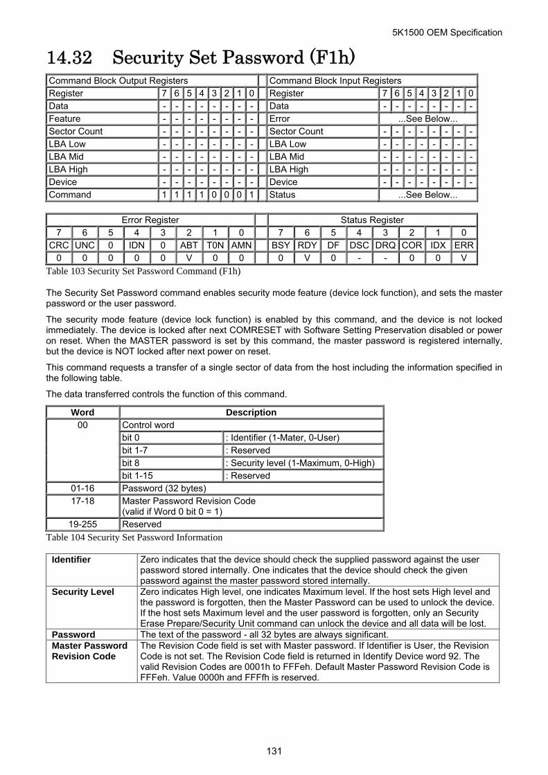
5K1500 OEM Specification
14.32 Security Set Password (F1h) Command Block Output Registers Command Block Input Registers Register 7 6 5 4 3 2 1 0 Register 7 6 5 4 3 2 1 0Data - - - - - - - - Data - - - - - - - -Feature - - - - - - - - Error ...See Below... Sector Count - - - - - - - - Sector Count - - - - - - - -LBA Low - - - - - - - - LBA Low - - - - - - - -LBA Mid - - - - - - - - LBA Mid - - - - - - - -LBA High - - - - - - - - LBA High - - - - - - - -Device - - - - - - - - Device - - - - - - - -Command 1 1 1 1 0 0 0 1 Status ...See Below...
Error Register Status Register
7 6 5 4 3 2 1 0 7 6 5 4 3 2 1 0 CRC UNC 0 IDN 0 ABT T0N AMN BSY RDY DF DSC DRQ COR IDX ERR
0 0 0 0 0 V 0 0 0 V 0 - - 0 0 V
Table 103 Security Set Password Command (F1h)
The Security Set Password command enables security mode feature (device lock function), and sets the master password or the user password.
The security mode feature (device lock function) is enabled by this command, and the device is not locked immediately. The device is locked after next COMRESET with Software Setting Preservation disabled or power on reset. When the MASTER password is set by this command, the master password is registered internally, but the device is NOT locked after next power on reset.
This command requests a transfer of a single sector of data from the host including the information specified in the following table.
The data transferred controls the function of this command.
Word Description Control word bit 0 : Identifier (1-Mater, 0-User) bit 1-7 : Reserved bit 8 : Security level (1-Maximum, 0-High)
00
bit 1-15 : Reserved 01-16 Password (32 bytes) 17-18 Master Password Revision Code
(valid if Word 0 bit 0 = 1) 19-255 Reserved
Table 104 Security Set Password Information
Identifier Zero indicates that the device should check the supplied password against the user password stored internally. One indicates that the device should check the given password against the master password stored internally.
Security Level Zero indicates High level, one indicates Maximum level. If the host sets High level and the password is forgotten, then the Master Password can be used to unlock the device. If the host sets Maximum level and the user password is forgotten, only an Security Erase Prepare/Security Unit command can unlock the device and all data will be lost.
Password The text of the password - all 32 bytes are always significant. Master Password Revision Code
The Revision Code field is set with Master password. If Identifier is User, the Revision Code is not set. The Revision Code field is returned in Identify Device word 92. The valid Revision Codes are 0001h to FFFeh. Default Master Password Revision Code is FFFeh. Value 0000h and FFFfh is reserved.
131

5K1500 OEM Specification
The setting of the Identifier and Security level bits interact as follows. Identifier=User / Security level = High The password supplied with the command will be saved as the new user password. The security mode feature (lock function) will be enabled from the next power on. The file may then be unlocked by either the user password or the previously set master password.
Identifier=Master / Security level = High This combination will set a master password but will NOT enable the security mode feature (lock function).
Identifier=User / Security level = Maximum The password supplied with the command will be saved as the new user password. The security mode feature (lock function) will be enabled from the next power on. The file may then be unlocked by only the user password. The master password previously set is still stored in the file but may NOT be used to unlock the device.
Identifier=Master / Security level = Maximum This combination will set a master password but will NOT enable the security mode feature (lock function).
132
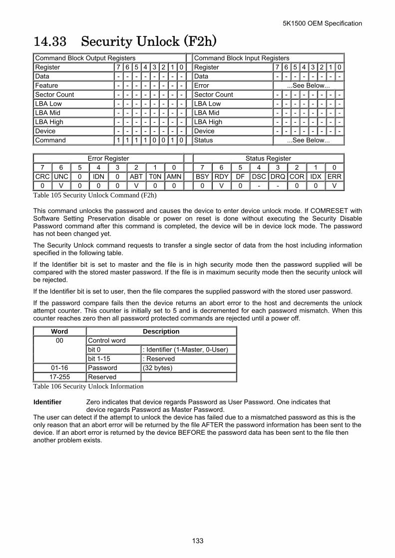
5K1500 OEM Specification
14.33 Security Unlock (F2h) Command Block Output Registers Command Block Input Registers Register 7 6 5 4 3 2 1 0 Register 7 6 5 4 3 2 1 0Data - - - - - - - - Data - - - - - - - -Feature - - - - - - - - Error ...See Below... Sector Count - - - - - - - - Sector Count - - - - - - - -LBA Low - - - - - - - - LBA Low - - - - - - - -LBA Mid - - - - - - - - LBA Mid - - - - - - - -LBA High - - - - - - - - LBA High - - - - - - - -Device - - - - - - - - Device - - - - - - - -Command 1 1 1 1 0 0 1 0 Status ...See Below...
Error Register Status Register
7 6 5 4 3 2 1 0 7 6 5 4 3 2 1 0 CRC UNC 0 IDN 0 ABT T0N AMN BSY RDY DF DSC DRQ COR IDX ERR
0 V 0 0 0 V 0 0 0 V 0 - - 0 0 V
Table 105 Security Unlock Command (F2h)
This command unlocks the password and causes the device to enter device unlock mode. If COMRESET with Software Setting Preservation disable or power on reset is done without executing the Security Disable Password command after this command is completed, the device will be in device lock mode. The password has not been changed yet.
The Security Unlock command requests to transfer a single sector of data from the host including information specified in the following table.
If the Identifier bit is set to master and the file is in high security mode then the password supplied will be compared with the stored master password. If the file is in maximum security mode then the security unlock will be rejected.
If the Identifier bit is set to user, then the file compares the supplied password with the stored user password.
If the password compare fails then the device returns an abort error to the host and decrements the unlock attempt counter. This counter is initially set to 5 and is decremented for each password mismatch. When this counter reaches zero then all password protected commands are rejected until a power off.
Word Description Control word bit 0 : Identifier (1-Master, 0-User)
00 bit 1-15 : Reserved
01-16 Password (32 bytes) 17-255 Reserved
Table 106 Security Unlock Information
Identifier Zero indicates that device regards Password as User Password. One indicates that device regards Password as Master Password.
The user can detect if the attempt to unlock the device has failed due to a mismatched password as this is the only reason that an abort error will be returned by the file AFTER the password information has been sent to the device. If an abort error is returned by the device BEFORE the password data has been sent to the file then another problem exists.
133
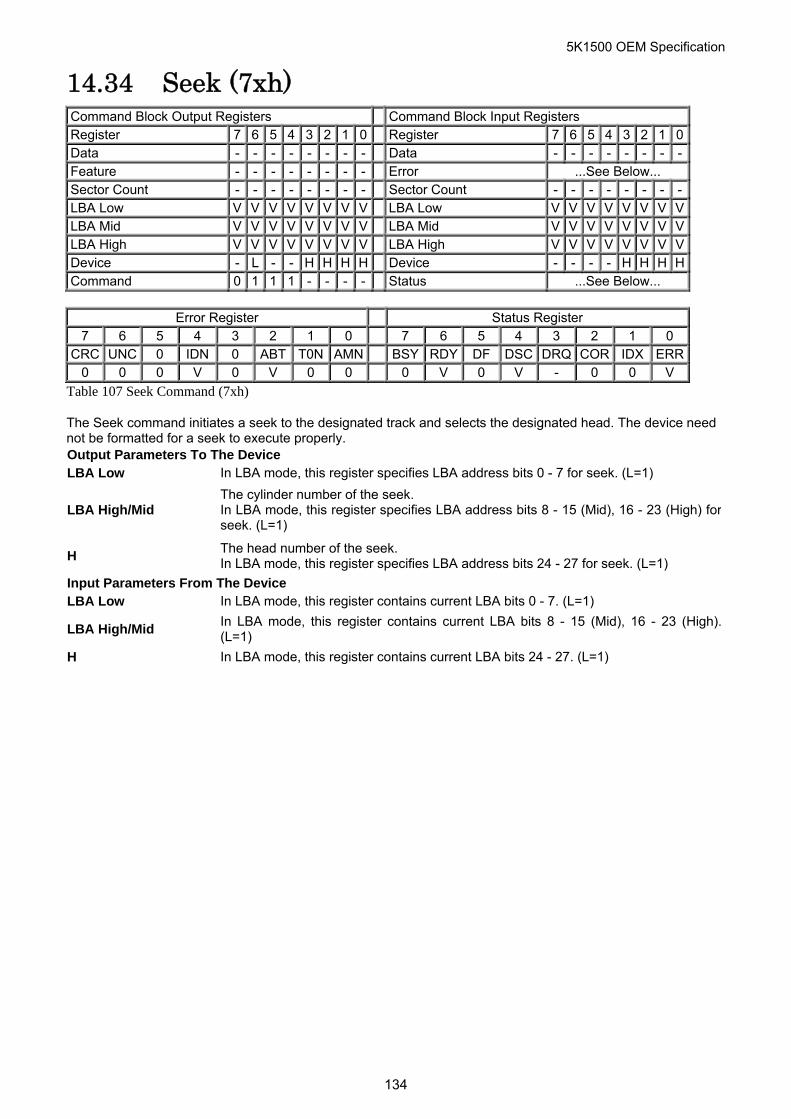
5K1500 OEM Specification
14.34 Seek (7xh) Command Block Output Registers Command Block Input Registers Register 7 6 5 4 3 2 1 0 Register 7 6 5 4 3 2 1 0Data - - - - - - - - Data - - - - - - - -Feature - - - - - - - - Error ...See Below... Sector Count - - - - - - - - Sector Count - - - - - - - -LBA Low V V V V V V V V LBA Low V V V V V V V VLBA Mid V V V V V V V V LBA Mid V V V V V V V VLBA High V V V V V V V V LBA High V V V V V V V VDevice - L - - H H H H Device - - - - H H H HCommand 0 1 1 1 - - - - Status ...See Below...
Error Register Status Register
7 6 5 4 3 2 1 0 7 6 5 4 3 2 1 0 CRC UNC 0 IDN 0 ABT T0N AMN BSY RDY DF DSC DRQ COR IDX ERR
0 0 0 V 0 V 0 0 0 V 0 V - 0 0 V
Table 107 Seek Command (7xh)
The Seek command initiates a seek to the designated track and selects the designated head. The device need not be formatted for a seek to execute properly. Output Parameters To The Device LBA Low In LBA mode, this register specifies LBA address bits 0 - 7 for seek. (L=1)
LBA High/Mid The cylinder number of the seek. In LBA mode, this register specifies LBA address bits 8 - 15 (Mid), 16 - 23 (High) forseek. (L=1)
H The head number of the seek. In LBA mode, this register specifies LBA address bits 24 - 27 for seek. (L=1)
Input Parameters From The Device LBA Low In LBA mode, this register contains current LBA bits 0 - 7. (L=1)
LBA High/Mid In LBA mode, this register contains current LBA bits 8 - 15 (Mid), 16 - 23 (High).(L=1)
H In LBA mode, this register contains current LBA bits 24 - 27. (L=1)
134
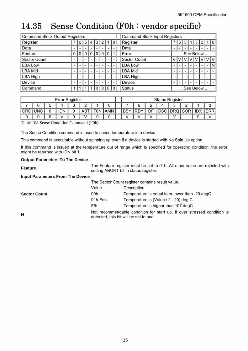
5K1500 OEM Specification
14.35 Sense Condition (F0h : vendor specific) Command Block Output Registers Command Block Input Registers Register 7 6 5 4 3 2 1 0 Register 7 6 5 4 3 2 1 0Data - - - - - - - - Data - - - - - - - -Feature 0 0 0 0 0 0 0 1 Error ...See Below... Sector Count - - - - - - - - Sector Count V V V V V V V VLBA Low - - - - - - - - LBA Low - - - - - - - NLBA Mid - - - - - - - - LBA Mid - - - - - - - -LBA High - - - - - - - - LBA High - - - - - - - -Device - - - - - - - - Device - - - - - - - -Command 1 1 1 1 0 0 0 0 Status ...See Below...
Error Register Status Register
7 6 5 4 3 2 1 0 7 6 5 4 3 2 1 0 CRC UNC 0 IDN 0 ABT T0N AMN BSY RDY DF DSC DRQ COR IDX ERR
0 0 0 V 0 V 0 0 V V V - V - 0 V
Table 108 Sense Condition Command (F0h)
The Sense Condition command is used to sense temperature in a device.
This command is executable without spinning up even if a device is started with No Spin Up option.
If this command is issued at the temperature out of range which is specified for operating condition, the error might be returned with IDN bit 1.
Output Parameters To The Device
Feature The Feature register must be set to 01h. All other value are rejected withsetting ABORT bit in status register.
Input Parameters From The Device The Sector Count register contains result value. Value Description
00h Temperature is equal to or lower than -20 degC
01h-Feh Temperature is (Value / 2 - 20) deg C Sector Count
Ffh Temperature is higher than 107 degC
N Not recommendable condition for start up. If over stressed condition is detected, this bit will be set to one.
135
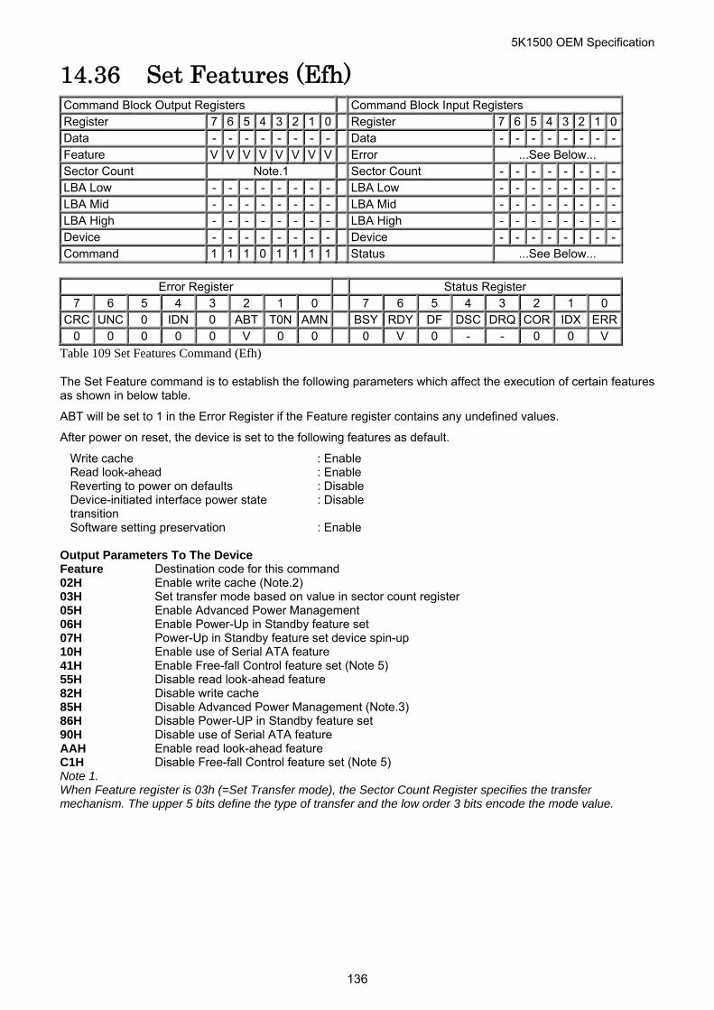
5K1500 OEM Specification
14.36 Set Features (Efh) Command Block Output Registers Command Block Input Registers Register 7 6 5 4 3 2 1 0 Register 7 6 5 4 3 2 1 0Data - - - - - - - - Data - - - - - - - -Feature V V V V V V V V Error ...See Below... Sector Count Note.1 Sector Count - - - - - - - -LBA Low - - - - - - - - LBA Low - - - - - - - -LBA Mid - - - - - - - - LBA Mid - - - - - - - -LBA High - - - - - - - - LBA High - - - - - - - -Device - - - - - - - - Device - - - - - - - -Command 1 1 1 0 1 1 1 1 Status ...See Below...
Error Register Status Register
7 6 5 4 3 2 1 0 7 6 5 4 3 2 1 0 CRC UNC 0 IDN 0 ABT T0N AMN BSY RDY DF DSC DRQ COR IDX ERR
0 0 0 0 0 V 0 0 0 V 0 - - 0 0 V
Table 109 Set Features Command (Efh)
The Set Feature command is to establish the following parameters which affect the execution of certain features as shown in below table.
ABT will be set to 1 in the Error Register if the Feature register contains any undefined values.
After power on reset, the device is set to the following features as default.
Write cache : Enable Read look-ahead : Enable Reverting to power on defaults : Disable Device-initiated interface power state transition
: Disable
Software setting preservation : Enable
Output Parameters To The Device Feature Destination code for this command 02H Enable write cache (Note.2) 03H Set transfer mode based on value in sector count register 05H Enable Advanced Power Management 06H Enable Power-Up in Standby feature set 07H Power-Up in Standby feature set device spin-up 10H Enable use of Serial ATA feature 41H Enable Free-fall Control feature set (Note 5) 55H Disable read look-ahead feature 82H Disable write cache 85H Disable Advanced Power Management (Note.3) 86H Disable Power-UP in Standby feature set 90H Disable use of Serial ATA feature AAH Enable read look-ahead feature C1H Disable Free-fall Control feature set (Note 5) Note 1. When Feature register is 03h (=Set Transfer mode), the Sector Count Register specifies the transfer mechanism. The upper 5 bits define the type of transfer and the low order 3 bits encode the mode value.
136
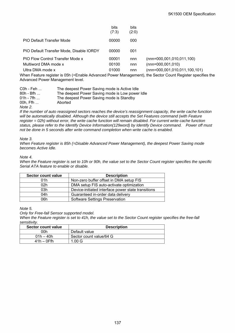
5K1500 OEM Specification
bits (7:3)
bits (2:0)
PIO Default Transfer Mode 00000 000
PIO Default Transfer Mode, Disable IORDY 00000 001
PIO Flow Control Transfer Mode x 00001 nnn (nnn=000,001,010,011,100) Multiword DMA mode x 00100 nnn (nnn=000,001,010)
Ultra DMA mode x 01000 nnn (nnn=000,001,010,011,100,101) When Feature register is 05h (=Enable Advanced Power Management), the Sector Count Register specifies the Advanced Power Management level. C0h - Feh ... The deepest Power Saving mode is Active Idle 80h - Bfh ... The deepest Power Saving mode is Low power Idle 01h - 7fh ... The deepest Power Saving mode is Standby 00h, Ffh ... Aborted Note 2. If the number of auto reassigned sectors reaches the device’s reassignment capacity, the write cache function will be automatically disabled. Although the device still accepts the Set Features command (with Feature register = 02h) without error, the write cache function will remain disabled. For current write cache function status, please refer to the Identify Device Information(129word) by Identify Device command. Power off must not be done in 5 seconds after write command completion when write cache is enabled. Note 3. When Feature register is 85h (=Disable Advanced Power Management), the deepest Power Saving mode becomes Active Idle. Note 4. When the Feature register is set to 10h or 90h, the value set to the Sector Count register specifies the specific Serial ATA feature to enable or disable.
Sector count value Description 01h Non-zero buffer offset in DMA setup FIS 02h DMA setup FIS auto-activate optimization 03h Device-initiated interface power state transitions 04h Guaranteed in-order data delivery 06h Software Settings Preservation
Note 5. Only for Free-fall Sensor supported model. When the Feature register is set to 41h, the value set to the Sector Count register specifies the free-fall sensitivity.
Sector count value Description 00h Default value
01h – 40h Sector count value/64 G 41h – 0Ffh 1.00 G
137
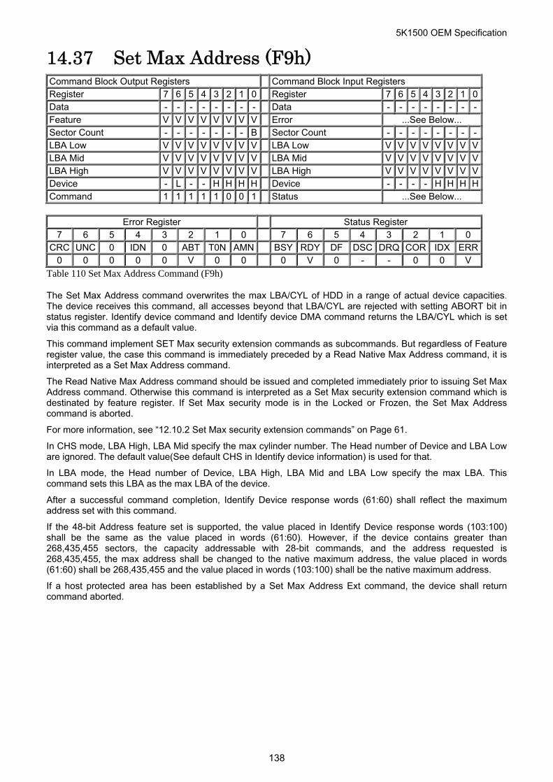
5K1500 OEM Specification
14.37 Set Max Address (F9h) Command Block Output Registers Command Block Input Registers Register 7 6 5 4 3 2 1 0 Register 7 6 5 4 3 2 1 0Data - - - - - - - - Data - - - - - - - -Feature V V V V V V V V Error ...See Below... Sector Count - - - - - - - B Sector Count - - - - - - - -LBA Low V V V V V V V V LBA Low V V V V V V V VLBA Mid V V V V V V V V LBA Mid V V V V V V V VLBA High V V V V V V V V LBA High V V V V V V V VDevice - L - - H H H H Device - - - - H H H HCommand 1 1 1 1 1 0 0 1 Status ...See Below...
Error Register Status Register
7 6 5 4 3 2 1 0 7 6 5 4 3 2 1 0 CRC UNC 0 IDN 0 ABT T0N AMN BSY RDY DF DSC DRQ COR IDX ERR
0 0 0 0 0 V 0 0 0 V 0 - - 0 0 V
Table 110 Set Max Address Command (F9h)
The Set Max Address command overwrites the max LBA/CYL of HDD in a range of actual device capacities. The device receives this command, all accesses beyond that LBA/CYL are rejected with setting ABORT bit in status register. Identify device command and Identify device DMA command returns the LBA/CYL which is set via this command as a default value.
This command implement SET Max security extension commands as subcommands. But regardless of Feature register value, the case this command is immediately preceded by a Read Native Max Address command, it is interpreted as a Set Max Address command.
The Read Native Max Address command should be issued and completed immediately prior to issuing Set Max Address command. Otherwise this command is interpreted as a Set Max security extension command which is destinated by feature register. If Set Max security mode is in the Locked or Frozen, the Set Max Address command is aborted.
For more information, see “12.10.2 Set Max security extension commands” on Page 61.
In CHS mode, LBA High, LBA Mid specify the max cylinder number. The Head number of Device and LBA Low are ignored. The default value(See default CHS in Identify device information) is used for that.
In LBA mode, the Head number of Device, LBA High, LBA Mid and LBA Low specify the max LBA. This command sets this LBA as the max LBA of the device.
After a successful command completion, Identify Device response words (61:60) shall reflect the maximum address set with this command.
If the 48-bit Address feature set is supported, the value placed in Identify Device response words (103:100) shall be the same as the value placed in words (61:60). However, if the device contains greater than 268,435,455 sectors, the capacity addressable with 28-bit commands, and the address requested is 268,435,455, the max address shall be changed to the native maximum address, the value placed in words (61:60) shall be 268,435,455 and the value placed in words (103:100) shall be the native maximum address.
If a host protected area has been established by a Set Max Address Ext command, the device shall return command aborted.
138
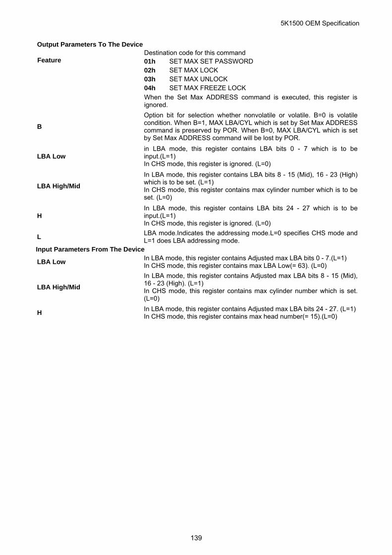
5K1500 OEM Specification
Output Parameters To The Device
Destination code for this command 01h SET MAX SET PASSWORD 02h SET MAX LOCK 03h SET MAX UNLOCK 04h SET MAX FREEZE LOCK
Feature When the Set Max ADDRESS command is executed, this register is
ignored.
B
Option bit for selection whether nonvolatile or volatile. B=0 is volatilecondition. When B=1, MAX LBA/CYL which is set by Set Max ADDRESScommand is preserved by POR. When B=0, MAX LBA/CYL which is setby Set Max ADDRESS command will be lost by POR.
LBA Low in LBA mode, this register contains LBA bits 0 - 7 which is to be input.(L=1) In CHS mode, this register is ignored. (L=0)
LBA High/Mid
In LBA mode, this register contains LBA bits 8 - 15 (Mid), 16 - 23 (High) which is to be set. (L=1) In CHS mode, this register contains max cylinder number which is to beset. (L=0)
H In LBA mode, this register contains LBA bits 24 - 27 which is to be input.(L=1) In CHS mode, this register is ignored. (L=0)
L LBA mode.Indicates the addressing mode.L=0 specifies CHS mode andL=1 does LBA addressing mode.
Input Parameters From The Device
LBA Low In LBA mode, this register contains Adjusted max LBA bits 0 - 7.(L=1) In CHS mode, this register contains max LBA Low(= 63). (L=0)
LBA High/Mid
In LBA mode, this register contains Adjusted max LBA bits 8 - 15 (Mid), 16 - 23 (High). (L=1) In CHS mode, this register contains max cylinder number which is set.(L=0)
H In LBA mode, this register contains Adjusted max LBA bits 24 - 27. (L=1)In CHS mode, this register contains max head number(= 15).(L=0)
139
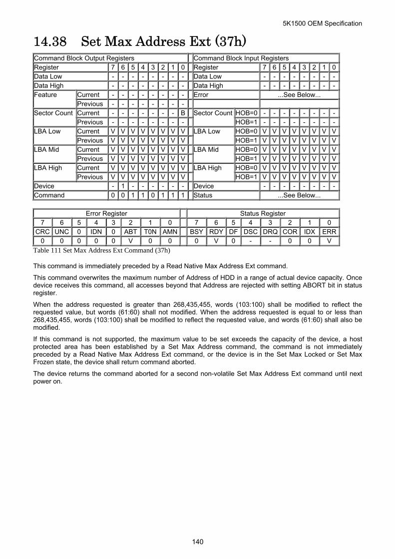
5K1500 OEM Specification
14.38 Set Max Address Ext (37h) Command Block Output Registers Command Block Input Registers Register 7 6 5 4 3 2 1 0 Register 7 6 5 4 3 2 1 0Data Low - - - - - - - - Data Low - - - - - - - -Data High - - - - - - - - Data High - - - - - - - -
Current - - - - - - - - Error ...See Below... Feature Previous - - - - - - - - Current - - - - - - - B HOB=0 - - - - - - - -Sector Count Previous - - - - - - - -
Sector CountHOB=1 - - - - - - - -
Current V V V V V V V V HOB=0 V V V V V V V VLBA Low Previous V V V V V V V V
LBA Low HOB=1 V V V V V V V V
Current V V V V V V V V HOB=0 V V V V V V V VLBA Mid Previous V V V V V V V V
LBA Mid HOB=1 V V V V V V V V
Current V V V V V V V V HOB=0 V V V V V V V VLBA High Previous V V V V V V V V
LBA High HOB=1 V V V V V V V V
Device - 1 - - - - - - Device - - - - - - - -Command 0 0 1 1 0 1 1 1 Status ...See Below...
Error Register Status Register
7 6 5 4 3 2 1 0 7 6 5 4 3 2 1 0 CRC UNC 0 IDN 0 ABT T0N AMN BSY RDY DF DSC DRQ COR IDX ERR
0 0 0 0 0 V 0 0 0 V 0 - - 0 0 V
Table 111 Set Max Address Ext Command (37h)
This command is immediately preceded by a Read Native Max Address Ext command.
This command overwrites the maximum number of Address of HDD in a range of actual device capacity. Once device receives this command, all accesses beyond that Address are rejected with setting ABORT bit in status register.
When the address requested is greater than 268,435,455, words (103:100) shall be modified to reflect the requested value, but words (61:60) shall not modified. When the address requested is equal to or less than 268,435,455, words (103:100) shall be modified to reflect the requested value, and words (61:60) shall also be modified.
If this command is not supported, the maximum value to be set exceeds the capacity of the device, a host protected area has been established by a Set Max Address command, the command is not immediately preceded by a Read Native Max Address Ext command, or the device is in the Set Max Locked or Set Max Frozen state, the device shall return command aborted.
The device returns the command aborted for a second non-volatile Set Max Address Ext command until next power on.
140
5K1500 OEM Specification
Output Parameters To The Device B Option bit for selection whether nonvolatile or volatile. B=0 is volatile
condition. When B=1, Max Address which is set by Set Max Address Ext command is preserved by POR. When B=0, Max Address which is set by Set Max Address Ext command will be lost by POR.
LBA Low Current Set Max LBA (7:0). LBA Low Previous Set Max LBA (31:24). LBA Mid Current Set Max LBA (15:8). LBA Mid Previous Set Max LBA (39:32). LBA High Current Set Max LBA (23:16). LBA High Previous Set Max LBA (47:40). Input Parameters From The Device LBA Low (HOB=0) Set Max LBA (7:0). LBA Low (HOB=1) Set Max LBA (31:24). LBA Mid (HOB=0) Set Max LBA (15:8). LBA Mid (HOB=1) Set Max LBA (39:32). LBA High (HOB=0) Set Max LBA (23:16). LBA High (HOB=1) Set Max LBA (47:40).
141
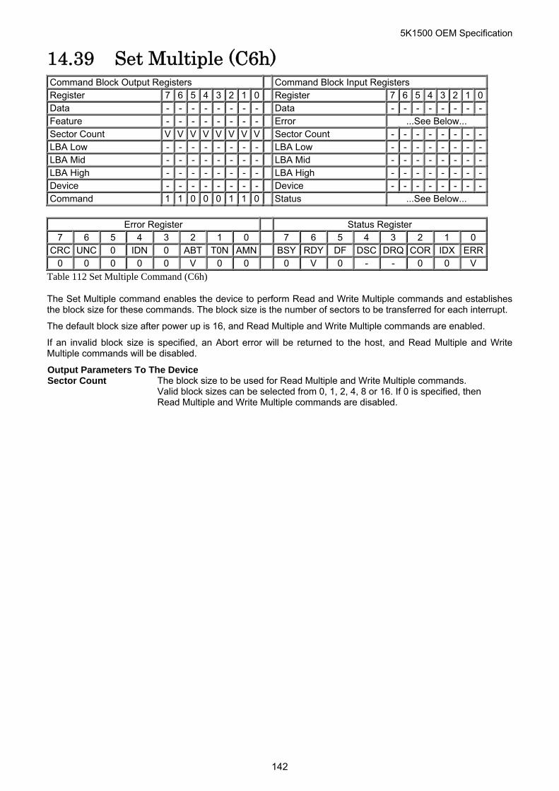
5K1500 OEM Specification
14.39 Set Multiple (C6h) Command Block Output Registers Command Block Input Registers Register 7 6 5 4 3 2 1 0 Register 7 6 5 4 3 2 1 0Data - - - - - - - - Data - - - - - - - -Feature - - - - - - - - Error ...See Below... Sector Count V V V V V V V V Sector Count - - - - - - - -LBA Low - - - - - - - - LBA Low - - - - - - - -LBA Mid - - - - - - - - LBA Mid - - - - - - - -LBA High - - - - - - - - LBA High - - - - - - - -Device - - - - - - - - Device - - - - - - - -Command 1 1 0 0 0 1 1 0 Status ...See Below...
Error Register Status Register
7 6 5 4 3 2 1 0 7 6 5 4 3 2 1 0 CRC UNC 0 IDN 0 ABT T0N AMN BSY RDY DF DSC DRQ COR IDX ERR
0 0 0 0 0 V 0 0 0 V 0 - - 0 0 V
Table 112 Set Multiple Command (C6h)
The Set Multiple command enables the device to perform Read and Write Multiple commands and establishes the block size for these commands. The block size is the number of sectors to be transferred for each interrupt.
The default block size after power up is 16, and Read Multiple and Write Multiple commands are enabled.
If an invalid block size is specified, an Abort error will be returned to the host, and Read Multiple and Write Multiple commands will be disabled.
Output Parameters To The Device Sector Count The block size to be used for Read Multiple and Write Multiple commands.
Valid block sizes can be selected from 0, 1, 2, 4, 8 or 16. If 0 is specified, then Read Multiple and Write Multiple commands are disabled.
142
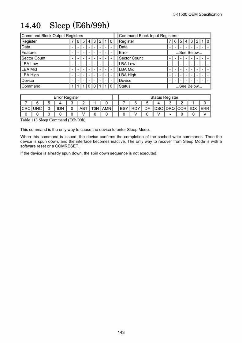
5K1500 OEM Specification
14.40 Sleep (E6h/99h) Command Block Output Registers Command Block Input Registers Register 7 6 5 4 3 2 1 0 Register 7 6 5 4 3 2 1 0Data - - - - - - - - Data - - - - - - - -Feature - - - - - - - - Error ...See Below... Sector Count - - - - - - - - Sector Count - - - - - - - -LBA Low - - - - - - - - LBA Low - - - - - - - -LBA Mid - - - - - - - - LBA Mid - - - - - - - -LBA High - - - - - - - - LBA High - - - - - - - -Device - - - - - - - - Device - - - - - - - -Command 1 1 1 0 0 1 1 0 Status ...See Below...
Error Register Status Register
7 6 5 4 3 2 1 0 7 6 5 4 3 2 1 0 CRC UNC 0 IDN 0 ABT T0N AMN BSY RDY DF DSC DRQ COR IDX ERR
0 0 0 0 0 V 0 0 0 V 0 V - 0 0 V
Table 113 Sleep Command (E6h/99h)
This command is the only way to cause the device to enter Sleep Mode.
When this command is issued, the device confirms the completion of the cached write commands. Then the device is spun down, and the interface becomes inactive. The only way to recover from Sleep Mode is with a software reset or a COMRESET.
If the device is already spun down, the spin down sequence is not executed.
143
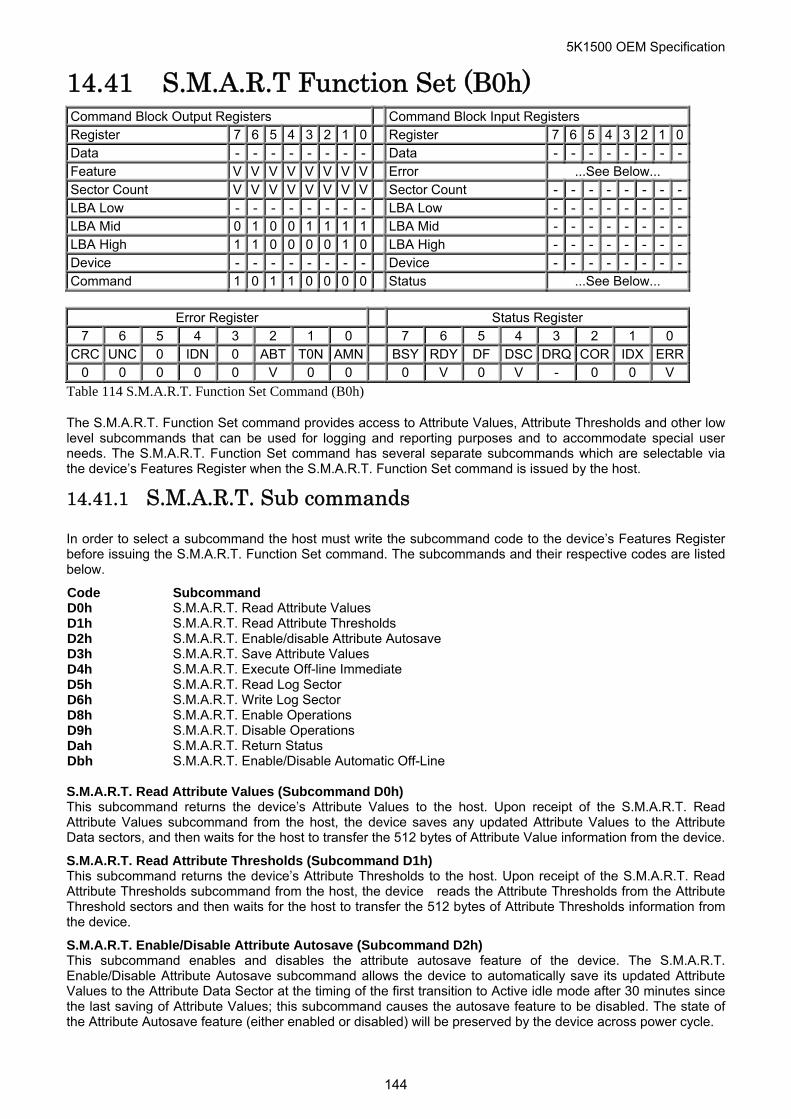
5K1500 OEM Specification
14.41 S.M.A.R.T Function Set (B0h) Command Block Output Registers Command Block Input Registers Register 7 6 5 4 3 2 1 0 Register 7 6 5 4 3 2 1 0Data - - - - - - - - Data - - - - - - - -Feature V V V V V V V V Error ...See Below... Sector Count V V V V V V V V Sector Count - - - - - - - -LBA Low - - - - - - - - LBA Low - - - - - - - -LBA Mid 0 1 0 0 1 1 1 1 LBA Mid - - - - - - - -LBA High 1 1 0 0 0 0 1 0 LBA High - - - - - - - -Device - - - - - - - - Device - - - - - - - -Command 1 0 1 1 0 0 0 0 Status ...See Below...
Error Register Status Register
7 6 5 4 3 2 1 0 7 6 5 4 3 2 1 0 CRC UNC 0 IDN 0 ABT T0N AMN BSY RDY DF DSC DRQ COR IDX ERR
0 0 0 0 0 V 0 0 0 V 0 V - 0 0 V
Table 114 S.M.A.R.T. Function Set Command (B0h)
The S.M.A.R.T. Function Set command provides access to Attribute Values, Attribute Thresholds and other low level subcommands that can be used for logging and reporting purposes and to accommodate special user needs. The S.M.A.R.T. Function Set command has several separate subcommands which are selectable via the device’s Features Register when the S.M.A.R.T. Function Set command is issued by the host.
14.41.1 S.M.A.R.T. Sub commands
In order to select a subcommand the host must write the subcommand code to the device’s Features Register before issuing the S.M.A.R.T. Function Set command. The subcommands and their respective codes are listed below.
Code Subcommand D0h S.M.A.R.T. Read Attribute Values D1h S.M.A.R.T. Read Attribute Thresholds D2h S.M.A.R.T. Enable/disable Attribute Autosave D3h S.M.A.R.T. Save Attribute Values D4h S.M.A.R.T. Execute Off-line Immediate D5h S.M.A.R.T. Read Log Sector D6h S.M.A.R.T. Write Log Sector D8h S.M.A.R.T. Enable Operations D9h S.M.A.R.T. Disable Operations Dah S.M.A.R.T. Return Status Dbh S.M.A.R.T. Enable/Disable Automatic Off-Line S.M.A.R.T. Read Attribute Values (Subcommand D0h) This subcommand returns the device’s Attribute Values to the host. Upon receipt of the S.M.A.R.T. Read Attribute Values subcommand from the host, the device saves any updated Attribute Values to the Attribute Data sectors, and then waits for the host to transfer the 512 bytes of Attribute Value information from the device.
S.M.A.R.T. Read Attribute Thresholds (Subcommand D1h) This subcommand returns the device’s Attribute Thresholds to the host. Upon receipt of the S.M.A.R.T. Read Attribute Thresholds subcommand from the host, the device reads the Attribute Thresholds from the Attribute Threshold sectors and then waits for the host to transfer the 512 bytes of Attribute Thresholds information from the device.
S.M.A.R.T. Enable/Disable Attribute Autosave (Subcommand D2h) This subcommand enables and disables the attribute autosave feature of the device. The S.M.A.R.T. Enable/Disable Attribute Autosave subcommand allows the device to automatically save its updated Attribute Values to the Attribute Data Sector at the timing of the first transition to Active idle mode after 30 minutes since the last saving of Attribute Values; this subcommand causes the autosave feature to be disabled. The state of the Attribute Autosave feature (either enabled or disabled) will be preserved by the device across power cycle.
144
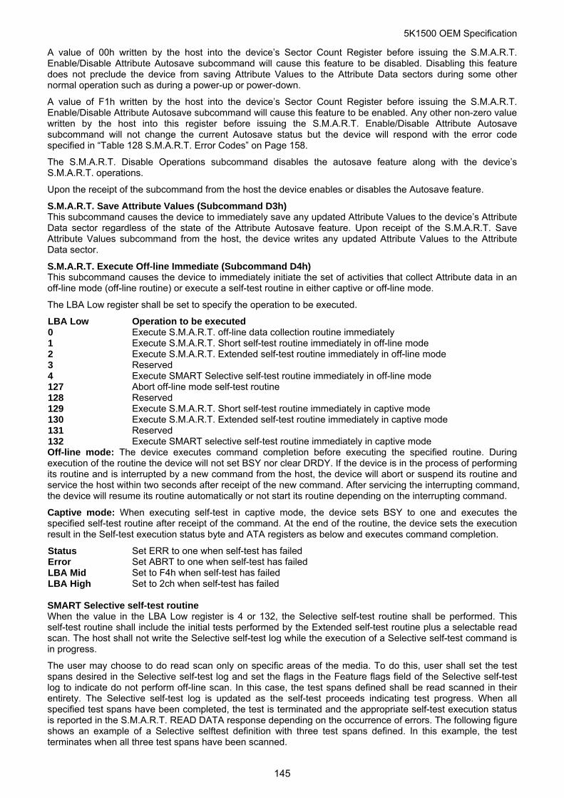
5K1500 OEM Specification
A value of 00h written by the host into the device’s Sector Count Register before issuing the S.M.A.R.T. Enable/Disable Attribute Autosave subcommand will cause this feature to be disabled. Disabling this feature does not preclude the device from saving Attribute Values to the Attribute Data sectors during some other normal operation such as during a power-up or power-down.
A value of F1h written by the host into the device’s Sector Count Register before issuing the S.M.A.R.T. Enable/Disable Attribute Autosave subcommand will cause this feature to be enabled. Any other non-zero value written by the host into this register before issuing the S.M.A.R.T. Enable/Disable Attribute Autosave subcommand will not change the current Autosave status but the device will respond with the error code specified in “Table 128 S.M.A.R.T. Error Codes” on Page 158.
The S.M.A.R.T. Disable Operations subcommand disables the autosave feature along with the device’s S.M.A.R.T. operations.
Upon the receipt of the subcommand from the host the device enables or disables the Autosave feature.
S.M.A.R.T. Save Attribute Values (Subcommand D3h) This subcommand causes the device to immediately save any updated Attribute Values to the device’s Attribute Data sector regardless of the state of the Attribute Autosave feature. Upon receipt of the S.M.A.R.T. Save Attribute Values subcommand from the host, the device writes any updated Attribute Values to the Attribute Data sector.
S.M.A.R.T. Execute Off-line Immediate (Subcommand D4h) This subcommand causes the device to immediately initiate the set of activities that collect Attribute data in an off-line mode (off-line routine) or execute a self-test routine in either captive or off-line mode.
The LBA Low register shall be set to specify the operation to be executed.
LBA Low Operation to be executed 0 Execute S.M.A.R.T. off-line data collection routine immediately 1 Execute S.M.A.R.T. Short self-test routine immediately in off-line mode 2 Execute S.M.A.R.T. Extended self-test routine immediately in off-line mode 3 Reserved 4 Execute SMART Selective self-test routine immediately in off-line mode 127 Abort off-line mode self-test routine 128 Reserved 129 Execute S.M.A.R.T. Short self-test routine immediately in captive mode 130 Execute S.M.A.R.T. Extended self-test routine immediately in captive mode 131 Reserved 132 Execute SMART selective self-test routine immediately in captive mode Off-line mode: The device executes command completion before executing the specified routine. During execution of the routine the device will not set BSY nor clear DRDY. If the device is in the process of performing its routine and is interrupted by a new command from the host, the device will abort or suspend its routine and service the host within two seconds after receipt of the new command. After servicing the interrupting command, the device will resume its routine automatically or not start its routine depending on the interrupting command.
Captive mode: When executing self-test in captive mode, the device sets BSY to one and executes the specified self-test routine after receipt of the command. At the end of the routine, the device sets the execution result in the Self-test execution status byte and ATA registers as below and executes command completion.
Status Set ERR to one when self-test has failed Error Set ABRT to one when self-test has failed LBA Mid Set to F4h when self-test has failed LBA High Set to 2ch when self-test has failed SMART Selective self-test routine When the value in the LBA Low register is 4 or 132, the Selective self-test routine shall be performed. This self-test routine shall include the initial tests performed by the Extended self-test routine plus a selectable read scan. The host shall not write the Selective self-test log while the execution of a Selective self-test command is in progress.
The user may choose to do read scan only on specific areas of the media. To do this, user shall set the test spans desired in the Selective self-test log and set the flags in the Feature flags field of the Selective self-test log to indicate do not perform off-line scan. In this case, the test spans defined shall be read scanned in their entirety. The Selective self-test log is updated as the self-test proceeds indicating test progress. When all specified test spans have been completed, the test is terminated and the appropriate self-test execution status is reported in the S.M.A.R.T. READ DATA response depending on the occurrence of errors. The following figure shows an example of a Selective selftest definition with three test spans defined. In this example, the test terminates when all three test spans have been scanned.
145
5K1500 OEM Specification
Figure 9 Selective self-test test span example
After the scan of the selected spans described above, a user may wish to have the rest of media read scanned as an off-line scan. In this case, the user shall set the flag to enable off-line scan in addition to the other settings. If an error occurs during the scanning of the test spans, the error is reported in the self-test execution status in the S.M.A.R.T. READ DATA response and the off-line scan is not executed. When the test spans defined have been scanned, the device shall then set the offline scan pending and active flags in the Selective self-test log to one, the span under test to a value greater than five, the self-test execution status in the S.M.A.R.T. READ DATA response to 00h, set a value of 03h in the off-line data collection status in the S.M.A.R.T. READ DATA response and shall proceed to do an off-line read scan through all areas not included in the test spans. This off-line read scan shall completed as rapidly as possible, no pauses between block reads, and any errors encountered shall not be reported to the host. Instead error locations may be logged for future reallocation. If the device is powered-down before the off-line scan is completed, the off-line scan shall resume when the device is again powered up. From power-up, the resumption of the scan shall be delayed the time indicated in the Selective self-test pending time field in the Selective self-test log. During this delay time the pending flag shall be set to one and the active flag shall be set to zero in the Selective self-test log. Once the time expires, the active flag shall be set to one, and the off-line scan shall resume. When the entire media has been scanned, the off-line scan shall terminate, both the pending and active flags shall be cleared to zero, and the off-line data collection status in the S.M.A.R.T. READ DATA response shall be set to 02h indicating completion.
During execution of the Selective self-test, the self-test executions time byte in the Device S.M.A.R.T. Data Structure may be updated but the accuracy may not be exact because of the nature of the test span segments. For this reason, the time to complete off-line testing and the self-test polling times are not valid. Progress through the test spans is indicated in the selective self-test log.
A COMRESET or software reset shall abort the Selective self-test except when the pending bit is set to one in the Selective self-test log (see 14.41.7 Selective self-test log data structure). The receipt of a S.M.A.R.T. EXECUTE OFF-LINE IMMEDIATE command with 0fh, Abort off-line test routine, in the LBA Low register shall abort Selective self-test regardless of where the device is in the execution of the command. If a second self-test is issued while a selective self-test is in progress, the selective self-test is aborted and the newly requested self-test is executed.
146
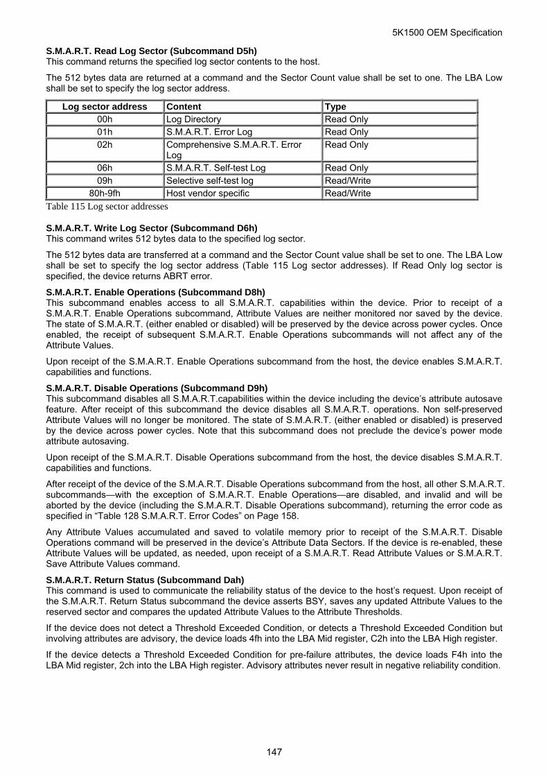
5K1500 OEM Specification
S.M.A.R.T. Read Log Sector (Subcommand D5h) This command returns the specified log sector contents to the host.
The 512 bytes data are returned at a command and the Sector Count value shall be set to one. The LBA Low shall be set to specify the log sector address.
Log sector address Content Type 00h Log Directory Read Only 01h S.M.A.R.T. Error Log Read Only 02h Comprehensive S.M.A.R.T. Error
Log Read Only
06h S.M.A.R.T. Self-test Log Read Only 09h Selective self-test log Read/Write
80h-9fh Host vendor specific Read/Write
Table 115 Log sector addresses
S.M.A.R.T. Write Log Sector (Subcommand D6h) This command writes 512 bytes data to the specified log sector.
The 512 bytes data are transferred at a command and the Sector Count value shall be set to one. The LBA Low shall be set to specify the log sector address (Table 115 Log sector addresses). If Read Only log sector is specified, the device returns ABRT error.
S.M.A.R.T. Enable Operations (Subcommand D8h) This subcommand enables access to all S.M.A.R.T. capabilities within the device. Prior to receipt of a S.M.A.R.T. Enable Operations subcommand, Attribute Values are neither monitored nor saved by the device. The state of S.M.A.R.T. (either enabled or disabled) will be preserved by the device across power cycles. Once enabled, the receipt of subsequent S.M.A.R.T. Enable Operations subcommands will not affect any of the Attribute Values.
Upon receipt of the S.M.A.R.T. Enable Operations subcommand from the host, the device enables S.M.A.R.T. capabilities and functions.
S.M.A.R.T. Disable Operations (Subcommand D9h) This subcommand disables all S.M.A.R.T.capabilities within the device including the device’s attribute autosave feature. After receipt of this subcommand the device disables all S.M.A.R.T. operations. Non self-preserved Attribute Values will no longer be monitored. The state of S.M.A.R.T. (either enabled or disabled) is preserved by the device across power cycles. Note that this subcommand does not preclude the device’s power mode attribute autosaving.
Upon receipt of the S.M.A.R.T. Disable Operations subcommand from the host, the device disables S.M.A.R.T. capabilities and functions.
After receipt of the device of the S.M.A.R.T. Disable Operations subcommand from the host, all other S.M.A.R.T. subcommands—with the exception of S.M.A.R.T. Enable Operations—are disabled, and invalid and will be aborted by the device (including the S.M.A.R.T. Disable Operations subcommand), returning the error code as specified in “Table 128 S.M.A.R.T. Error Codes” on Page 158.
Any Attribute Values accumulated and saved to volatile memory prior to receipt of the S.M.A.R.T. Disable Operations command will be preserved in the device’s Attribute Data Sectors. If the device is re-enabled, these Attribute Values will be updated, as needed, upon receipt of a S.M.A.R.T. Read Attribute Values or S.M.A.R.T. Save Attribute Values command.
S.M.A.R.T. Return Status (Subcommand Dah) This command is used to communicate the reliability status of the device to the host’s request. Upon receipt of the S.M.A.R.T. Return Status subcommand the device asserts BSY, saves any updated Attribute Values to the reserved sector and compares the updated Attribute Values to the Attribute Thresholds.
If the device does not detect a Threshold Exceeded Condition, or detects a Threshold Exceeded Condition but involving attributes are advisory, the device loads 4fh into the LBA Mid register, C2h into the LBA High register.
If the device detects a Threshold Exceeded Condition for pre-failure attributes, the device loads F4h into the LBA Mid register, 2ch into the LBA High register. Advisory attributes never result in negative reliability condition.
147
5K1500 OEM Specification
S.M.A.R.T. Enable/Disable Automatic Off-Line (Subcommand Dbh) This subcommand enables and disables the optional feature that cause the device to perform the set of off-line data collection activities that automatically collect attribute data in an off-line mode and then save this data to the device’s non-volatile memory. This subcommand may either cause the device to automatically initiate or resume performance of its off-line data collection activities or cause the automatic off-line data collection feature to be disabled. This subcommand also enables and disables the off-line read scanning feature that cause the device to perform the entire read scanning with defect reallocation as the part of the off-line data collection activities.
The Sector Count register shall be set to specify the feature to be enabled or disabled.
Sector Count Feature Description 00h Disable Automatic Off-line 01h Disable Off-line Read Scanning F8h Enable Automatic Off-line F9h Enable Off-line Read Scanning
A value of zero written by the host into the device’s Sector Count register before issuing this subcommand shall cause the automatic off-line data collection feature to be disabled. Disabling this feature does not preclude the device from saving attribute values to non-volatile memory during some other normal operation such as during a power-on or power-off sequence or during an error recovery sequence.
A value of one written by the host into the device’s Sector Count register before issuing this subcommand shall cause the off-line read scanning feature to be disabled. The Device does not perform the off-line read scanning at the off-line data collection activities which is initiated by the S.M.A.R.T. Execute Off-line Immediate (Subcommand D4h) or automatically if the off-line read scanning feature is disabled.
A value of F8h written by the host into the device’s Sector Count register before issuing this subcommand shall cause the automatic Off-line data collection feature to be enabled.
A value of F9 written by the host into the device’s Sector Count register before issuing this subcommand shall cause the off-line read scanning feature to be enabled. The Device perform the off-line read scanning at the off-line data collection activities which is initiated by the S.M.A.R.T. Execute Off-line Immediate(Subcommand D4h) even if the automatic off-line feature is disabled.
Any other non-zero value written by the host into this register before issuing this subcommand is vender specific and will not change the current Automatic Off-Line Data Collection and Off-line Read Scanning status, but device may respond with the error code specified in “Table 128 S.M.A.R.T. Error Codes” on Page 158.
148
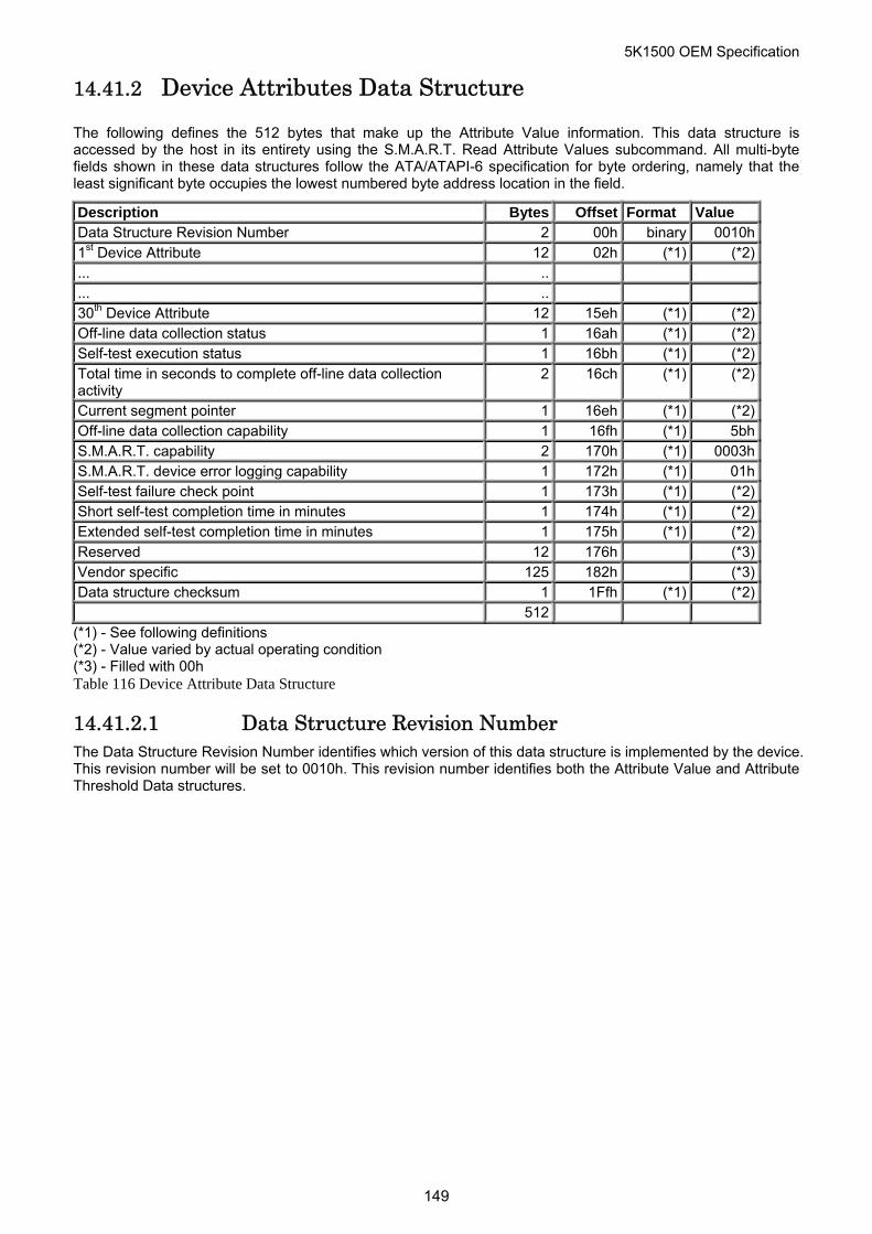
5K1500 OEM Specification
14.41.2 Device Attributes Data Structure
The following defines the 512 bytes that make up the Attribute Value information. This data structure is accessed by the host in its entirety using the S.M.A.R.T. Read Attribute Values subcommand. All multi-byte fields shown in these data structures follow the ATA/ATAPI-6 specification for byte ordering, namely that the least significant byte occupies the lowest numbered byte address location in the field.
Description Bytes Offset Format Value Data Structure Revision Number 2 00h binary 0010h1st Device Attribute 12 02h (*1) (*2)... .. ... .. 30th Device Attribute 12 15eh (*1) (*2)Off-line data collection status 1 16ah (*1) (*2)Self-test execution status 1 16bh (*1) (*2)Total time in seconds to complete off-line data collection activity
2 16ch (*1) (*2)
Current segment pointer 1 16eh (*1) (*2)Off-line data collection capability 1 16fh (*1) 5bhS.M.A.R.T. capability 2 170h (*1) 0003hS.M.A.R.T. device error logging capability 1 172h (*1) 01hSelf-test failure check point 1 173h (*1) (*2)Short self-test completion time in minutes 1 174h (*1) (*2)Extended self-test completion time in minutes 1 175h (*1) (*2)Reserved 12 176h (*3)Vendor specific 125 182h (*3)Data structure checksum 1 1Ffh (*1) (*2) 512
(*1) - See following definitions (*2) - Value varied by actual operating condition (*3) - Filled with 00h Table 116 Device Attribute Data Structure
14.41.2.1 Data Structure Revision Number The Data Structure Revision Number identifies which version of this data structure is implemented by the device. This revision number will be set to 0010h. This revision number identifies both the Attribute Value and Attribute Threshold Data structures.
149
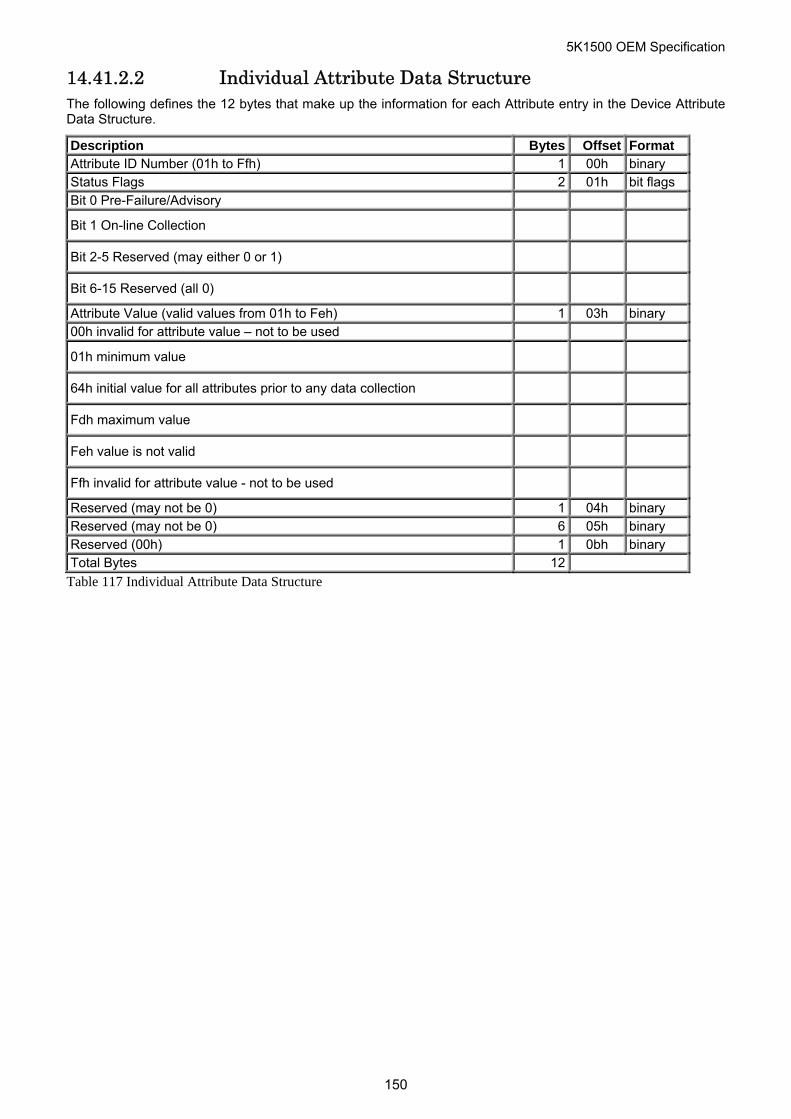
5K1500 OEM Specification
14.41.2.2 Individual Attribute Data Structure The following defines the 12 bytes that make up the information for each Attribute entry in the Device Attribute Data Structure.
Description Bytes Offset Format Attribute ID Number (01h to Ffh) 1 00h binary Status Flags 2 01h bit flags Bit 0 Pre-Failure/Advisory
Bit 1 On-line Collection
Bit 2-5 Reserved (may either 0 or 1)
Bit 6-15 Reserved (all 0)
Attribute Value (valid values from 01h to Feh) 1 03h binary 00h invalid for attribute value – not to be used
01h minimum value
64h initial value for all attributes prior to any data collection
Fdh maximum value
Feh value is not valid
Ffh invalid for attribute value - not to be used
Reserved (may not be 0) 1 04h binary Reserved (may not be 0) 6 05h binary Reserved (00h) 1 0bh binary Total Bytes 12
Table 117 Individual Attribute Data Structure
150
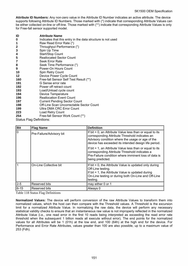
5K1500 OEM Specification
Attribute ID Numbers: Any non-zero value in the Attribute ID Number indicates an active attribute. The device supports following Attribute ID Numbers. Those marked with (*) indicate that corresponding Attribute Values can be either collected on-line or off-line. Those marked with (**) indicate that corresponding Attribute Values is only for Free-fall sensor supported model.
ID Attribute Name 0 Indicates that this entry in the data structure is not used 1 Raw Read Error Rate (*) 2 Throughput Performance (*) 3 Spin Up Time 4 Start/Stop Count 5 Reallocated Sector Count 7 Seek Error Rate 8 Seek Time Performance (*) 9 Power-On Hours Count 10 Spin Retry Count 12 Device Power Cycle Count 160 Free-fall Sensor Self Test Result (**) 191 G Sense error rate 192 Power off retract count 193 Load/Unload cycle count 194 Device Temperature 196 Reallocation Event Count 197 Current Pending Sector Count 198 Off-Line Scan Uncorrectable Sector Count 199 Ultra DMA CRC Error Count 223 Load Retry Count 254 Free-fall Sensor Work Count (**) Status Flag Definitions:
Bit Flag Name Definition 0 Pre-Failure/Advisory bit If bit = 0, an Attribute Value less than or equal to its
corresponding Attribute Threshold indicates an Advisory condition where the usage or age of the device has exceeded its intended design life period.
If bit = 1, an Attribute Value less than or equal to its corresponding Attribute Threshold indicates a Pre-Failure condition where imminent loss of data is being predicted.
1 On-Line Collective bit If bit = 0, the Attribute Value is updated only during Off-Line testing. If bit = 1, the Attribute Value is updated during On-Line testing or during both On-Line and Off-Line testing.
2-5 Reserved bits may either 0 or 1 6-15 Reserved bits Always 0
Table 118 Status Flag Definitions
Normalized Values: The device will perform conversion of the raw Attribute Values to transform them into normalized values, which the host can then compare with the Threshold values. A Threshold is the excursion limit for a normalized Attribute Value. In normalizing the raw data, the device will perform any necessary statistical validity checks to ensure that an instantaneous raw value is not improperly reflected in the normalized Attribute Value (i.e., one read error in the first 10 reads being interpreted as exceeding the read error rate threshold when the subsequent 1 billion reads all execute without error). The end points for the normalized values for all Attributes will be 1 (01h) at the low end, and 100 (64h) at the high end for the device. For Performance and Error Rate Attributes, values greater than 100 are also possible, up to a maximum value of 253 (Fdh).
151
5K1500 OEM Specification
14.41.2.3 Off-Line Data Collection Status The value of this byte defines the current status of the off-line activities of the device. Bit 7 indicates Automatic Off-Line Data Collection Status.
Bit 7 Automatic Off-Line Data Collection Status 0 Automatic Off-Line Data Collection is disabled. 1 Automatic Off-Line Data Collection is enabled. Bits 0 thru 6 represents a hexadecimal status value reported by the device.
Value Definition 0 Off-line data collection never started 2 All segments completed without errors. In this case, current segment pointer equals to total
segments required. 4 Off-line data collection suspended by interrupting command 5 Off-line data collecting aborted by interrupting command 6 Off-line data collection aborted with fatal error
14.41.2.4 Self-test execution status Bit Definition 0-3 Percent Self-test remaining
An approximation of the percent of the self-test routine remaining until completion in ten percent increments. Valid values are 0 through 9.
4-7 Current Self-test execution status 0 The self-test routine completed without error or has never been run 1 The self-test routine aborted by the host 2 The self-test routine interrupted by the host with a hard or soft reset 3 The device was unable to complete the self-test routine due to a fatal error or unknown
test error 4 The self-test routine completed with unknown element failure 5 The self-test routine completed with electrical element failure 6 The self-test routine completed with servo element failure 7 The self-test routine completed with read element failure 15 The self-test routine in progress
14.41.2.5 Total Time in Seconds to Complete Off-line Data Collection Activity
This field tells the host how many seconds the device requires to complete the off-line data collection activity.
s an off-line data collection activity. Because the number of segments is 1, 01h is always returned in this field.
14.41.2.6 Current Segment Pointer This byte is a counter indicating the next segment to execute a
152
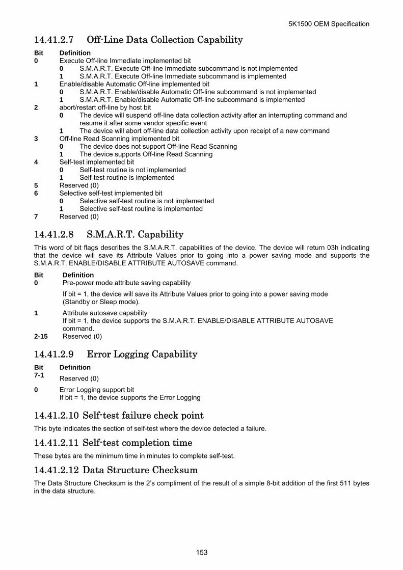
5K1500 OEM Specification
14.41.2.7 Off-Line Data Collection Capability Bit Definition 0 Execute Off-line Immediate implemented bit 0 S.M.A.R.T. Execute Off-line Immediate subcommand is not implemented 1 S.M.A.R.T. Execute Off-line Immediate subcommand is implemented 1 Enable/disable Automatic Off-line implemented bit 0 S.M.A.R.T. Enable/disable Automatic Off-line subcommand is not implemented 1 S.M.A.R.T. Enable/disable Automatic Off-line subcommand is implemented 2 abort/restart off-line by host bit 0 The device will suspend off-line data collection activity after an interrupting command and
resume it after some vendor specific event 1 The device will abort off-line data collection activity upon receipt of a new command 3 Off-line Read Scanning implemented bit 0 The device does not support Off-line Read Scanning 1 The device supports Off-line Read Scanning 4 Self-test implemented bit 0 Self-test routine is not implemented 1 Self-test routine is implemented 5 Reserved (0) 6 Selective self-test implemented bit 0 Selective self-test routine is not implemented 1 Selective self-test routine is implemented 7 Reserved (0)
14.41.2.8 S.M.A.R.T. Capability This word of bit flags describes the S.M.A.R.T. capabilities of the device. The device will return 03h indicating that the device will save its Attribute Values prior to going into a power saving mode and supports the S.M.A.R.T. ENABLE/DISABLE ATTRIBUTE AUTOSAVE command.
Bit Definition 0 Pre-power mode attribute saving capability
If bit = 1, the device will save its Attribute Values prior to going into a power saving mode (Standby or Sleep mode).
1 Attribute autosave capability If bit = 1, the device supports the S.M.A.R.T. ENABLE/DISABLE ATTRIBUTE AUTOSAVE command.
2-15 Reserved (0)
14.41.2.9 Error Logging Capability Bit Definition 7-1 Reserved (0)
0 Error Logging support bit If bit = 1, the device supports the Error Logging
14.41.2.10 Self-test failure check point
This byte indicates the section of self-test where the device detected a failure.
14.41.2.11 Self-test completion time These bytes are the minimum time in minutes to complete self-test.
14.41.2.12 Data Structure Checksum The Data Structure Checksum is the 2’s compliment of the result of a simple 8-bit addition of the first 511 bytes in the data structure.
153
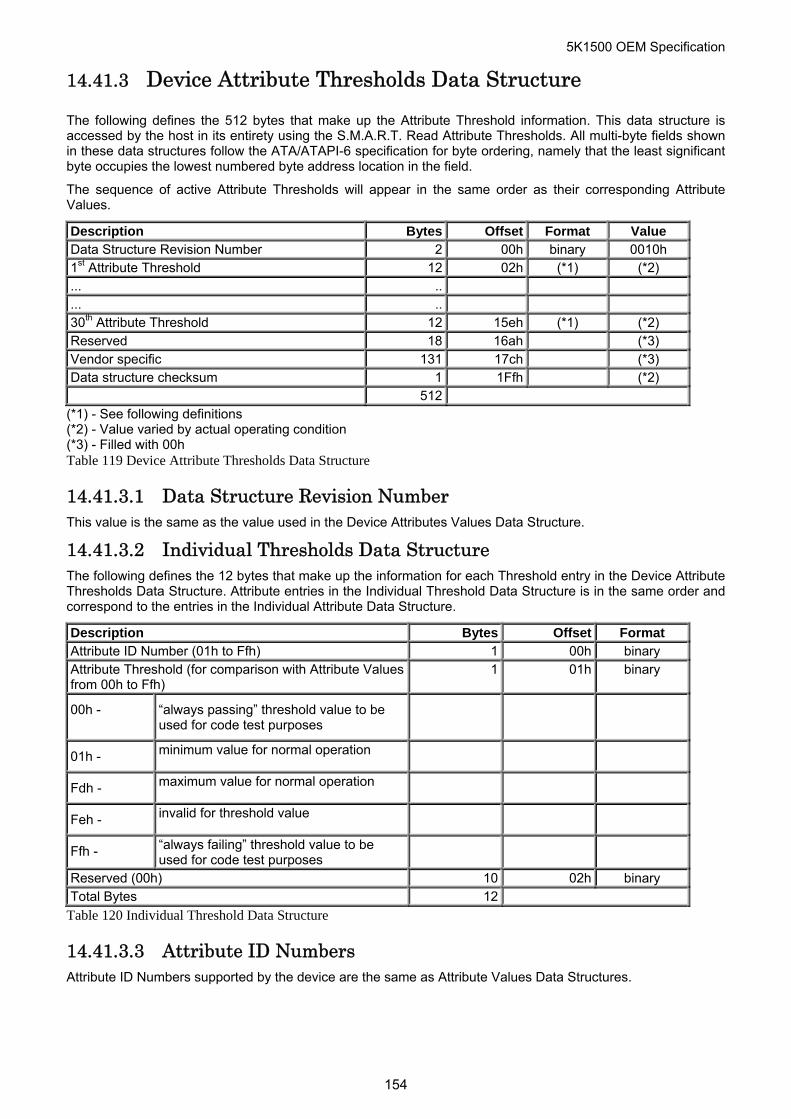
5K1500 OEM Specification
14.41.3 Device Attribute Thresholds Data Structure
The following defines the 512 bytes that make up the Attribute Threshold information. This data structure is accessed by the host in its entirety using the S.M.A.R.T. Read Attribute Thresholds. All multi-byte fields shown in these data structures follow the ATA/ATAPI-6 specification for byte ordering, namely that the least significant byte occupies the lowest numbered byte address location in the field.
The sequence of active Attribute Thresholds will appear in the same order as their corresponding Attribute Values.
Description Bytes Offset Format Value Data Structure Revision Number 2 00h binary 0010h 1st Attribute Threshold 12 02h (*1) (*2) ... .. ... .. 30th Attribute Threshold 12 15eh (*1) (*2) Reserved 18 16ah (*3) Vendor specific 131 17ch (*3) Data structure checksum 1 1Ffh (*2) 512
(*1) - See following definitions (*2) - Value varied by actual operating condition (*3) - Filled with 00h Table 119 Device Attribute Thresholds Data Structure
14.41.3.1 Data Structure Revision Number This value is the same as the value used in the Device Attributes Values Data Structure.
14.41.3.2 Individual Thresholds Data Structure The following defines the 12 bytes that make up the information for each Threshold entry in the Device Attribute Thresholds Data Structure. Attribute entries in the Individual Threshold Data Structure is in the same order and correspond to the entries in the Individual Attribute Data Structure.
Description Bytes Offset Format Attribute ID Number (01h to Ffh) 1 00h binary Attribute Threshold (for comparison with Attribute Values from 00h to Ffh)
1 01h binary
00h - “always passing” threshold value to be used for code test purposes
01h - minimum value for normal operation
Fdh - maximum value for normal operation
Feh - invalid for threshold value
Ffh - “always failing” threshold value to be used for code test purposes
Reserved (00h) 10 02h binary Total Bytes 12
Table 120 Individual Threshold Data Structure
14.41.3.3 Attribute ID Numbers Attribute ID Numbers supported by the device are the same as Attribute Values Data Structures.
154
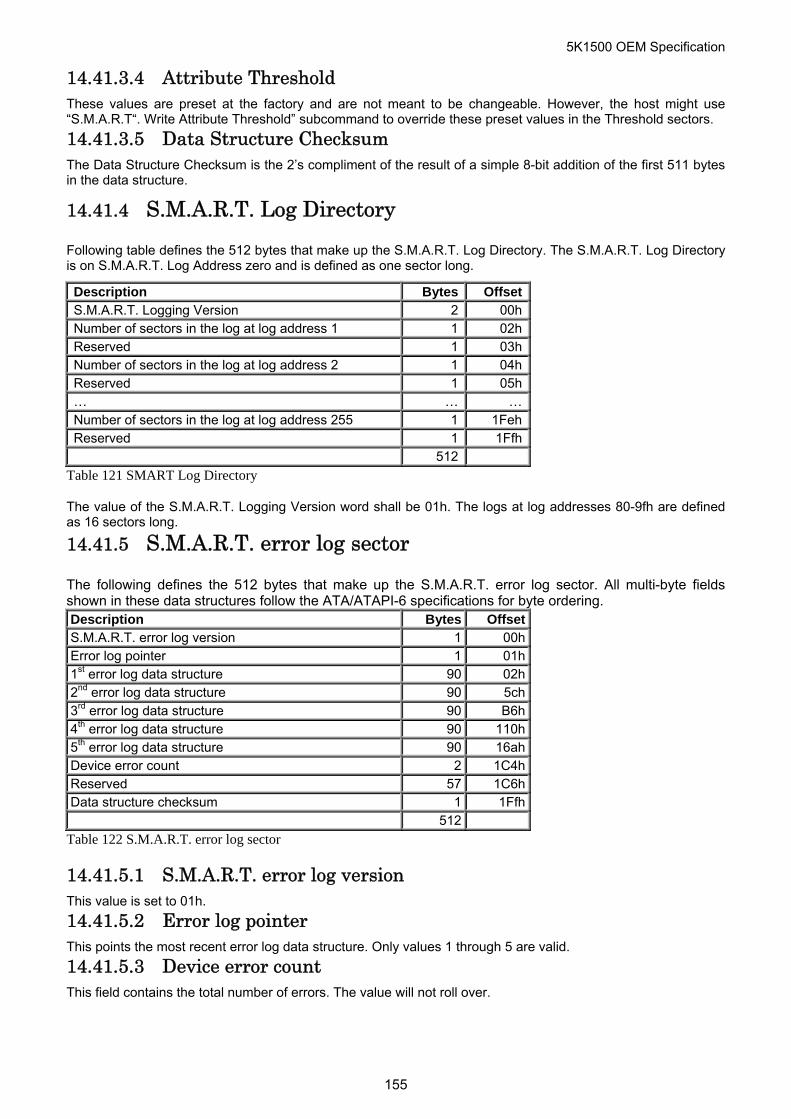
5K1500 OEM Specification
14.41.3.4 Attribute Threshold These values are preset at the factory and are not meant to be changeable. However, the host might use “S.M.A.R.T“. Write Attribute Threshold” subcommand to override these preset values in the Threshold sectors.
14.41.3.5 Data Structure Checksum The Data Structure Checksum is the 2’s compliment of the result of a simple 8-bit addition of the first 511 bytes in the data structure.
14.41.4 S.M.A.R.T. Log Directory
Following table defines the 512 bytes that make up the S.M.A.R.T. Log Directory. The S.M.A.R.T. Log Directory is on S.M.A.R.T. Log Address zero and is defined as one sector long.
Description Bytes OffsetS.M.A.R.T. Logging Version 2 00hNumber of sectors in the log at log address 1 1 02hReserved 1 03hNumber of sectors in the log at log address 2 1 04hReserved 1 05h… … …Number of sectors in the log at log address 255 1 1FehReserved 1 1Ffh 512
Table 121 SMART Log Directory
The value of the S.M.A.R.T. Logging Version word shall be 01h. The logs at log addresses 80-9fh are defined as 16 sectors long.
14.41.5 S.M.A.R.T. error log sector
The following defines the 512 bytes that make up the S.M.A.R.T. error log sector. All multi-byte fields shown in these data structures follow the ATA/ATAPI-6 specifications for byte ordering. Description Bytes OffsetS.M.A.R.T. error log version 1 00hError log pointer 1 01h1st error log data structure 90 02h2nd error log data structure 90 5ch3rd error log data structure 90 B6h4th error log data structure 90 110h5th error log data structure 90 16ahDevice error count 2 1C4hReserved 57 1C6hData structure checksum 1 1Ffh 512
Table 122 S.M.A.R.T. error log sector
14.41.5.1 S.M.A.R.T. error log version This value is set to 01h.
14.41.5.2 Error log pointer This points the most recent error log data structure. Only values 1 through 5 are valid.
14.41.5.3 Device error count This field contains the total number of errors. The value will not roll over.
155
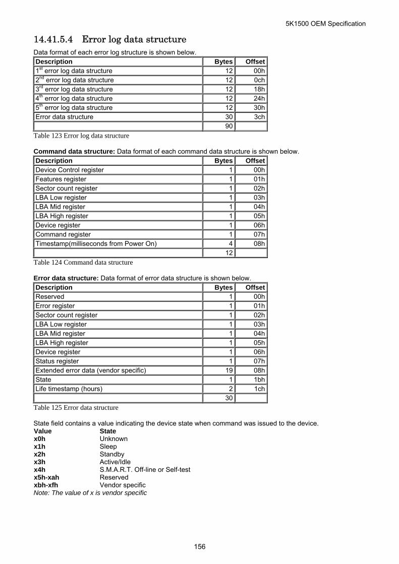
5K1500 OEM Specification
14.41.5.4 Error log data structure Data format of each error log structure is shown below. Description Bytes Offset1st error log data structure 12 00h2nd error log data structure 12 0ch3rd error log data structure 12 18h4th error log data structure 12 24h5th error log data structure 12 30hError data structure 30 3ch 90
Table 123 Error log data structure
Command data structure: Data format of each command data structure is shown below. Description Bytes OffsetDevice Control register 1 00hFeatures register 1 01hSector count register 1 02hLBA Low register 1 03hLBA Mid register 1 04hLBA High register 1 05hDevice register 1 06hCommand register 1 07hTimestamp(milliseconds from Power On) 4 08h 12
Table 124 Command data structure
Error data structure: Data format of error data structure is shown below. Description Bytes OffsetReserved 1 00hError register 1 01hSector count register 1 02hLBA Low register 1 03hLBA Mid register 1 04hLBA High register 1 05hDevice register 1 06hStatus register 1 07hExtended error data (vendor specific) 19 08hState 1 1bhLife timestamp (hours) 2 1ch 30
Table 125 Error data structure
State field contains a value indicating the device state when command was issued to the device. Value State x0h Unknown x1h Sleep x2h Standby x3h Active/Idle x4h S.M.A.R.T. Off-line or Self-test x5h-xah Reserved xbh-xfh Vendor specific Note: The value of x is vendor specific
156
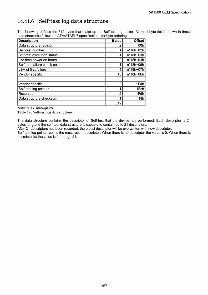
5K1500 OEM Specification
14.41.6 Self-test log data structure
The following defines the 512 bytes that make up the Self-test log sector. All multi-byte fields shown in these data structures follow the ATA/ATAPI-7 specifications for byte ordering. Description Bytes OffsetData structure revision 2 00hSelf-test number 1 n*18h+02hSelf-test execution status 1 n*18h+03hLife time power on hours 2 n*18h+04hSelf-test failure check point 1 n*18h+06hLBA of first failure 4 n*18h+07hVendor specific 15 n*18h+0bh... Vendor specific 2 1FahSelf-test log pointer 1 1FchReserved 2 1FdhData structure checksum 1 1Ffh 512
Note: n is 0 through 20 Table 126 Self-test log data structure
The data structure contains the descriptor of Self-test that the device has performed. Each descriptor is 24 bytes long and the self-test data structure is capable to contain up to 21 descriptors. After 21 descriptors has been recorded, the oldest descriptor will be overwritten with new descriptor. Self-test log pointer points the most recent descriptor. When there is no descriptor the value is 0. When there is descriptor(s) the value is 1 through 21.
157
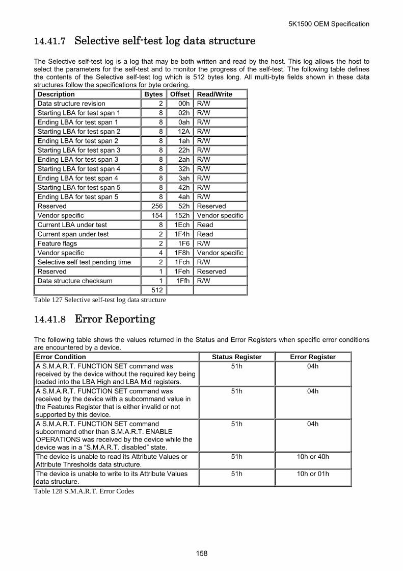
5K1500 OEM Specification
14.41.7 Selective self-test log data structure
The Selective self-test log is a log that may be both written and read by the host. This log allows the host to select the parameters for the self-test and to monitor the progress of the self-test. The following table defines the contents of the Selective self-test log which is 512 bytes long. All multi-byte fields shown in these data structures follow the specifications for byte ordering. Description Bytes Offset Read/Write Data structure revision 2 00h R/W Starting LBA for test span 1 8 02h R/W Ending LBA for test span 1 8 0ah R/W Starting LBA for test span 2 8 12A R/W Ending LBA for test span 2 8 1ah R/W Starting LBA for test span 3 8 22h R/W Ending LBA for test span 3 8 2ah R/W Starting LBA for test span 4 8 32h R/W Ending LBA for test span 4 8 3ah R/W Starting LBA for test span 5 8 42h R/W Ending LBA for test span 5 8 4ah R/W Reserved 256 52h Reserved Vendor specific 154 152h Vendor specificCurrent LBA under test 8 1Ech Read Current span under test 2 1F4h Read Feature flags 2 1F6 R/W Vendor specific 4 1F8h Vendor specificSelective self test pending time 2 1Fch R/W Reserved 1 1Feh Reserved Data structure checksum 1 1Ffh R/W 512
Table 127 Selective self-test log data structure
14.41.8 Error Reporting
The following table shows the values returned in the Status and Error Registers when specific error conditions are encountered by a device. Error Condition Status Register Error Register A S.M.A.R.T. FUNCTION SET command was received by the device without the required key being loaded into the LBA High and LBA Mid registers.
51h 04h
A S.M.A.R.T. FUNCTION SET command was received by the device with a subcommand value in the Features Register that is either invalid or not supported by this device.
51h 04h
A S.M.A.R.T. FUNCTION SET command subcommand other than S.M.A.R.T. ENABLE OPERATIONS was received by the device while the device was in a “S.M.A.R.T. disabled” state.
51h 04h
The device is unable to read its Attribute Values or Attribute Thresholds data structure.
51h 10h or 40h
The device is unable to write to its Attribute Values data structure.
51h 10h or 01h
Table 128 S.M.A.R.T. Error Codes
158
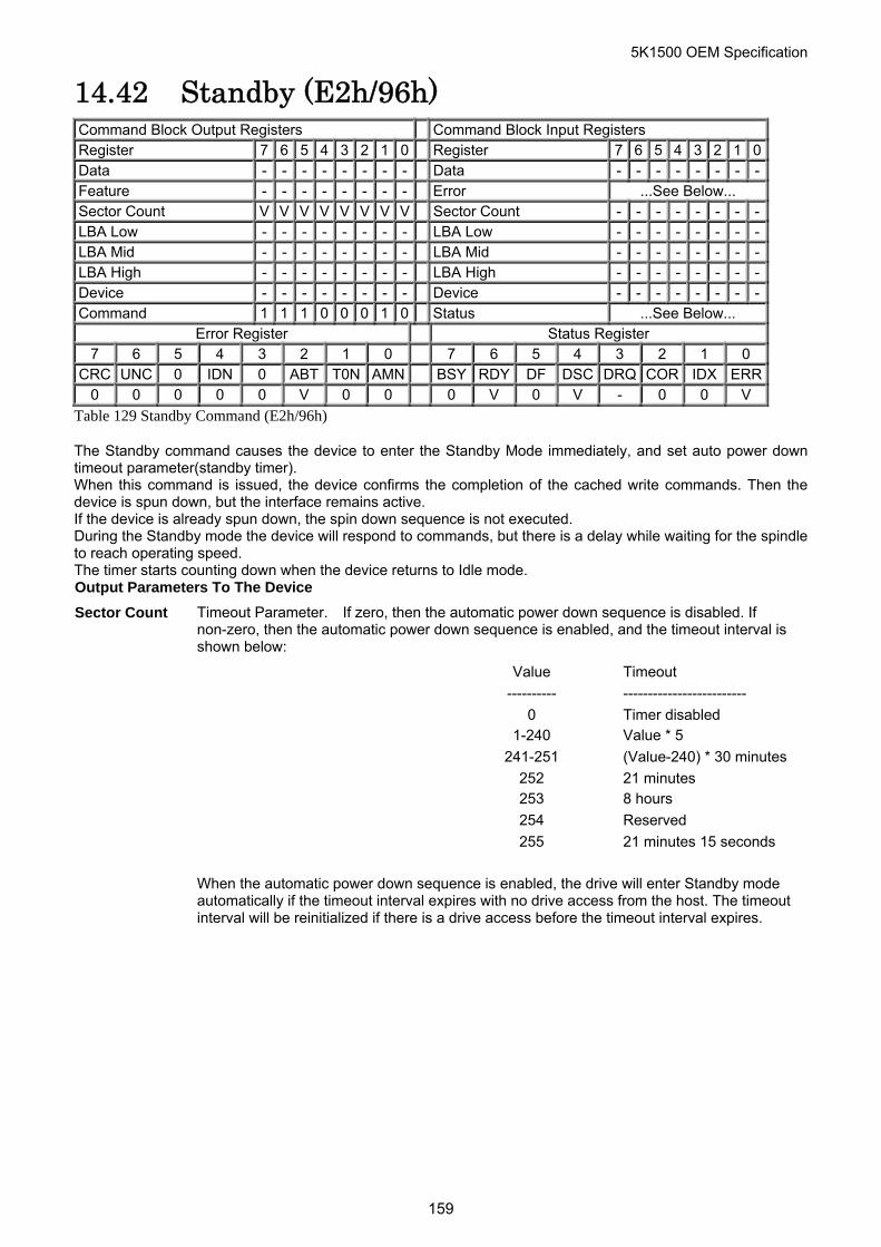
5K1500 OEM Specification
14.42 Standby (E2h/96h) Command Block Output Registers Command Block Input Registers Register 7 6 5 4 3 2 1 0 Register 7 6 5 4 3 2 1 0Data - - - - - - - - Data - - - - - - - -Feature - - - - - - - - Error ...See Below... Sector Count V V V V V V V V Sector Count - - - - - - - -LBA Low - - - - - - - - LBA Low - - - - - - - -LBA Mid - - - - - - - - LBA Mid - - - - - - - -LBA High - - - - - - - - LBA High - - - - - - - -Device - - - - - - - - Device - - - - - - - -Command 1 1 1 0 0 0 1 0 Status ...See Below...
Error Register Status Register 7 6 5 4 3 2 1 0 7 6 5 4 3 2 1 0
CRC UNC 0 IDN 0 ABT T0N AMN BSY RDY DF DSC DRQ COR IDX ERR0 0 0 0 0 V 0 0 0 V 0 V - 0 0 V
Table 129 Standby Command (E2h/96h)
The Standby command causes the device to enter the Standby Mode immediately, and set auto power down timeout parameter(standby timer). When this command is issued, the device confirms the completion of the cached write commands. Then the device is spun down, but the interface remains active. If the device is already spun down, the spin down sequence is not executed. During the Standby mode the device will respond to commands, but there is a delay while waiting for the spindle to reach operating speed. The timer starts counting down when the device returns to Idle mode. Output Parameters To The Device
Sector Count Timeout Parameter. If zero, then the automatic power down sequence is disabled. If non-zero, then the automatic power down sequence is enabled, and the timeout interval is shown below:
Value Timeout
---------- -------------------------
0 Timer disabled
1-240 Value * 5
241-251 (Value-240) * 30 minutes
252 21 minutes
253 8 hours
254 Reserved
255 21 minutes 15 seconds
When the automatic power down sequence is enabled, the drive will enter Standby mode
automatically if the timeout interval expires with no drive access from the host. The timeout interval will be reinitialized if there is a drive access before the timeout interval expires.
159
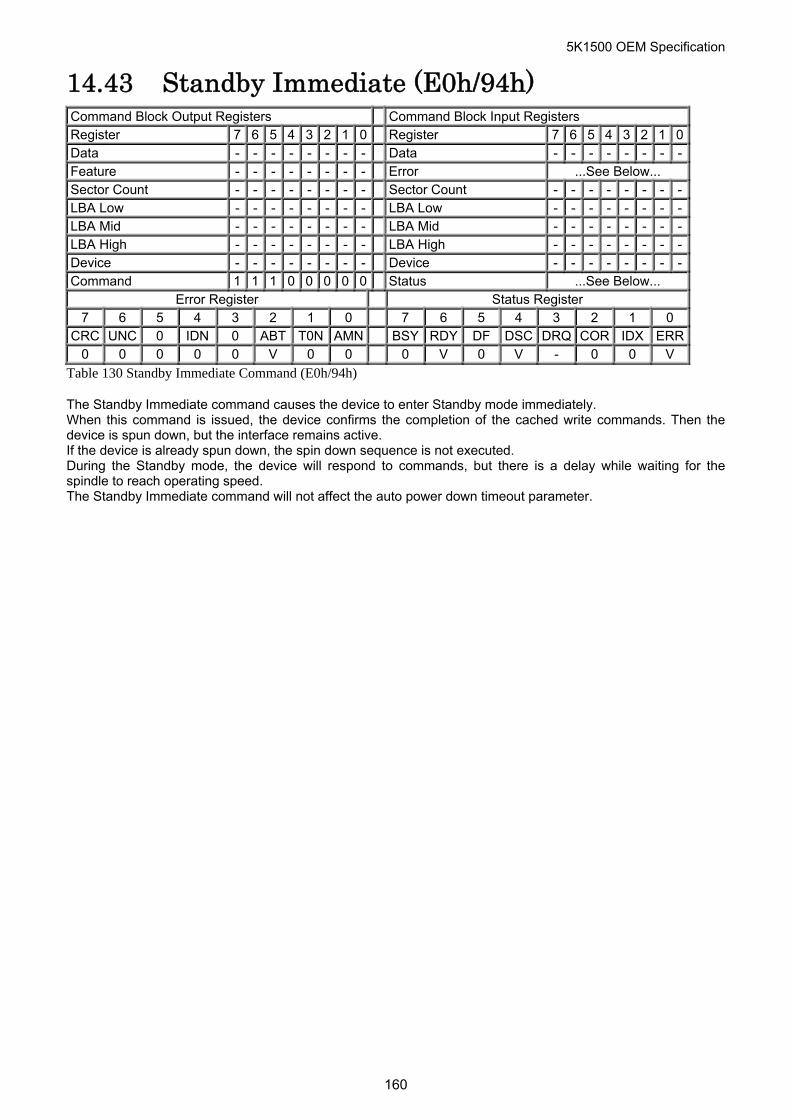
5K1500 OEM Specification
14.43 Standby Immediate (E0h/94h) Command Block Output Registers Command Block Input Registers Register 7 6 5 4 3 2 1 0 Register 7 6 5 4 3 2 1 0Data - - - - - - - - Data - - - - - - - -Feature - - - - - - - - Error ...See Below... Sector Count - - - - - - - - Sector Count - - - - - - - -LBA Low - - - - - - - - LBA Low - - - - - - - -LBA Mid - - - - - - - - LBA Mid - - - - - - - -LBA High - - - - - - - - LBA High - - - - - - - -Device - - - - - - - - Device - - - - - - - -Command 1 1 1 0 0 0 0 0 Status ...See Below...
Error Register Status Register 7 6 5 4 3 2 1 0 7 6 5 4 3 2 1 0
CRC UNC 0 IDN 0 ABT T0N AMN BSY RDY DF DSC DRQ COR IDX ERR0 0 0 0 0 V 0 0 0 V 0 V - 0 0 V
Table 130 Standby Immediate Command (E0h/94h)
The Standby Immediate command causes the device to enter Standby mode immediately. When this command is issued, the device confirms the completion of the cached write commands. Then the device is spun down, but the interface remains active. If the device is already spun down, the spin down sequence is not executed. During the Standby mode, the device will respond to commands, but there is a delay while waiting for the spindle to reach operating speed. The Standby Immediate command will not affect the auto power down timeout parameter.
160
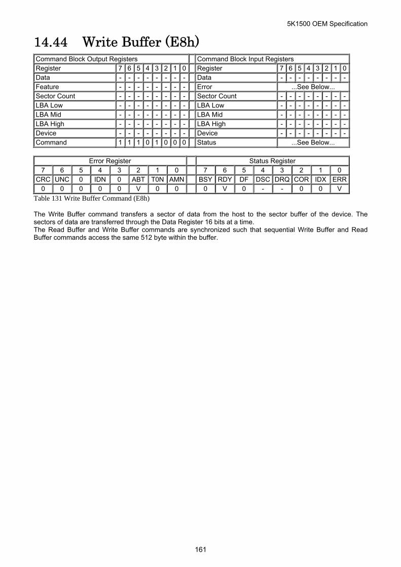
5K1500 OEM Specification
14.44 Write Buffer (E8h) Command Block Output Registers Command Block Input Registers Register 7 6 5 4 3 2 1 0 Register 7 6 5 4 3 2 1 0Data - - - - - - - - Data - - - - - - - -Feature - - - - - - - - Error ...See Below... Sector Count - - - - - - - - Sector Count - - - - - - - -LBA Low - - - - - - - - LBA Low - - - - - - - -LBA Mid - - - - - - - - LBA Mid - - - - - - - -LBA High - - - - - - - - LBA High - - - - - - - -Device - - - - - - - - Device - - - - - - - -Command 1 1 1 0 1 0 0 0 Status ...See Below...
Error Register Status Register
7 6 5 4 3 2 1 0 7 6 5 4 3 2 1 0 CRC UNC 0 IDN 0 ABT T0N AMN BSY RDY DF DSC DRQ COR IDX ERR
0 0 0 0 0 V 0 0 0 V 0 - - 0 0 V
Table 131 Write Buffer Command (E8h)
The Write Buffer command transfers a sector of data from the host to the sector buffer of the device. The sectors of data are transferred through the Data Register 16 bits at a time. The Read Buffer and Write Buffer commands are synchronized such that sequential Write Buffer and Read Buffer commands access the same 512 byte within the buffer.
161
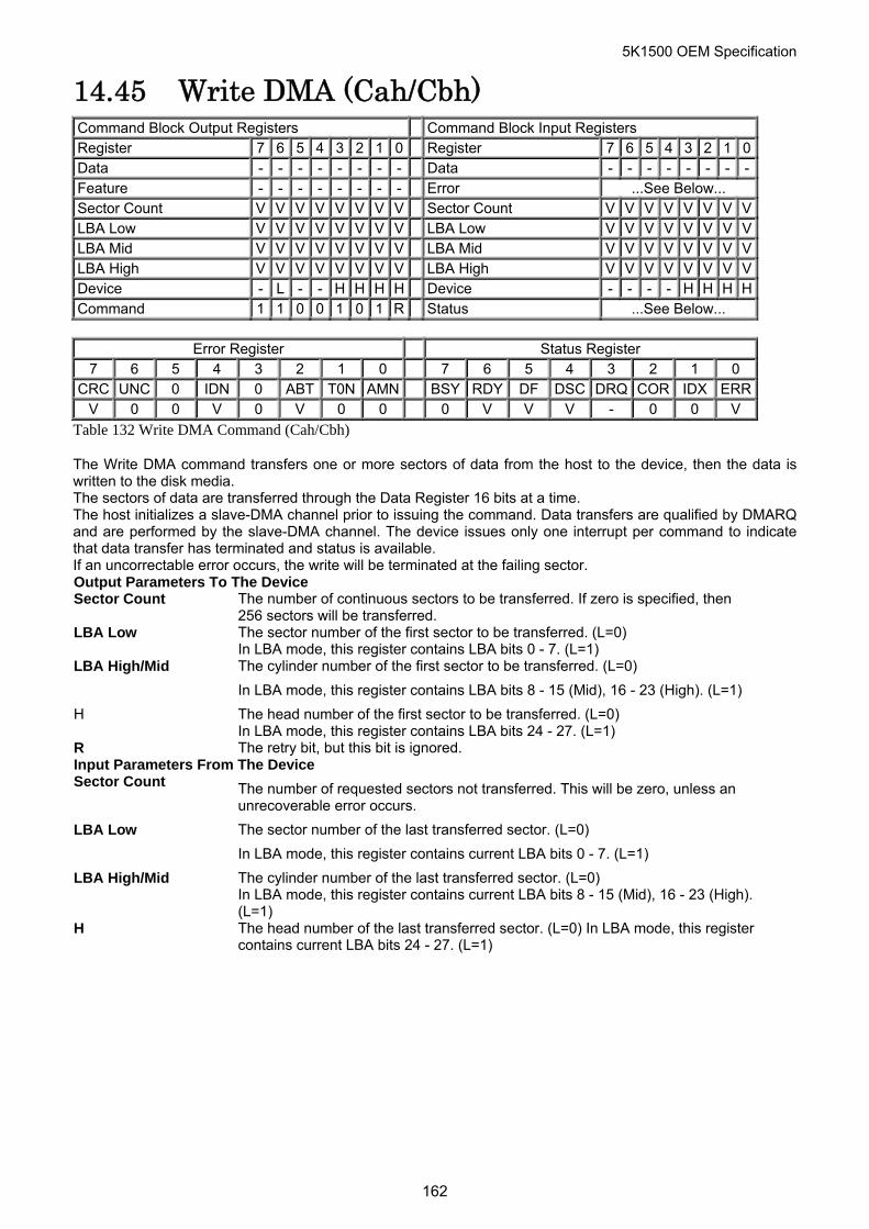
5K1500 OEM Specification
14.45 Write DMA (Cah/Cbh) Command Block Output Registers Command Block Input Registers Register 7 6 5 4 3 2 1 0 Register 7 6 5 4 3 2 1 0Data - - - - - - - - Data - - - - - - - -Feature - - - - - - - - Error ...See Below... Sector Count V V V V V V V V Sector Count V V V V V V V VLBA Low V V V V V V V V LBA Low V V V V V V V VLBA Mid V V V V V V V V LBA Mid V V V V V V V VLBA High V V V V V V V V LBA High V V V V V V V VDevice - L - - H H H H Device - - - - H H H HCommand 1 1 0 0 1 0 1 R Status ...See Below...
Error Register Status Register
7 6 5 4 3 2 1 0 7 6 5 4 3 2 1 0 CRC UNC 0 IDN 0 ABT T0N AMN BSY RDY DF DSC DRQ COR IDX ERR
V 0 0 V 0 V 0 0 0 V V V - 0 0 V
Table 132 Write DMA Command (Cah/Cbh)
The Write DMA command transfers one or more sectors of data from the host to the device, then the data is written to the disk media. The sectors of data are transferred through the Data Register 16 bits at a time. The host initializes a slave-DMA channel prior to issuing the command. Data transfers are qualified by DMARQ and are performed by the slave-DMA channel. The device issues only one interrupt per command to indicate that data transfer has terminated and status is available. If an uncorrectable error occurs, the write will be terminated at the failing sector. Output Parameters To The Device Sector Count The number of continuous sectors to be transferred. If zero is specified, then
256 sectors will be transferred. LBA Low The sector number of the first sector to be transferred. (L=0)
In LBA mode, this register contains LBA bits 0 - 7. (L=1) LBA High/Mid The cylinder number of the first sector to be transferred. (L=0)
In LBA mode, this register contains LBA bits 8 - 15 (Mid), 16 - 23 (High). (L=1)
H The head number of the first sector to be transferred. (L=0) In LBA mode, this register contains LBA bits 24 - 27. (L=1)
R The retry bit, but this bit is ignored. Input Parameters From The Device Sector Count The number of requested sectors not transferred. This will be zero, unless an
unrecoverable error occurs.
LBA Low The sector number of the last transferred sector. (L=0)
In LBA mode, this register contains current LBA bits 0 - 7. (L=1)
LBA High/Mid The cylinder number of the last transferred sector. (L=0) In LBA mode, this register contains current LBA bits 8 - 15 (Mid), 16 - 23 (High). (L=1)
H The head number of the last transferred sector. (L=0) In LBA mode, this register contains current LBA bits 24 - 27. (L=1)
162
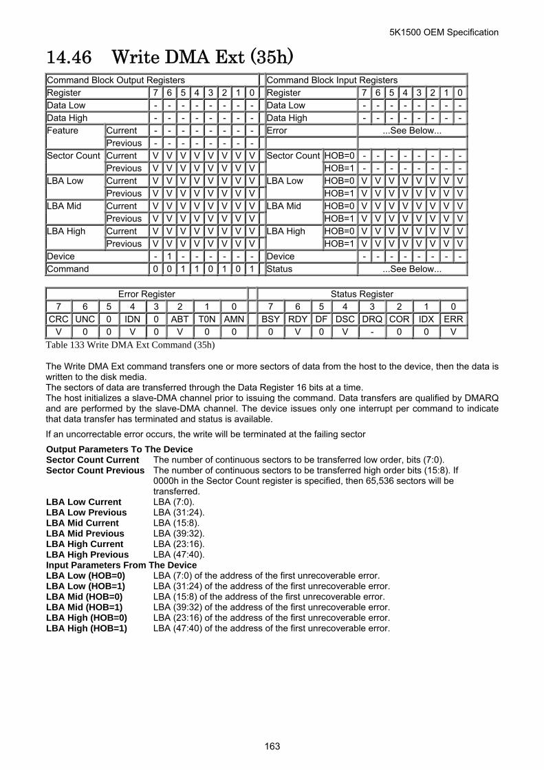
5K1500 OEM Specification
14.46 Write DMA Ext (35h) Command Block Output Registers Command Block Input Registers Register 7 6 5 4 3 2 1 0 Register 7 6 5 4 3 2 1 0Data Low - - - - - - - - Data Low - - - - - - - -Data High - - - - - - - - Data High - - - - - - - -
Current - - - - - - - - Error ...See Below... Feature Previous - - - - - - - - Current V V V V V V V V HOB=0 - - - - - - - -Sector Count Previous V V V V V V V V
Sector CountHOB=1 - - - - - - - -
Current V V V V V V V V HOB=0 V V V V V V V VLBA Low Previous V V V V V V V V
LBA Low HOB=1 V V V V V V V V
Current V V V V V V V V HOB=0 V V V V V V V VLBA Mid Previous V V V V V V V V
LBA Mid HOB=1 V V V V V V V V
Current V V V V V V V V HOB=0 V V V V V V V VLBA High Previous V V V V V V V V
LBA High HOB=1 V V V V V V V V
Device - 1 - - - - - - Device - - - - - - - -Command 0 0 1 1 0 1 0 1 Status ...See Below...
Error Register Status Register
7 6 5 4 3 2 1 0 7 6 5 4 3 2 1 0 CRC UNC 0 IDN 0 ABT T0N AMN BSY RDY DF DSC DRQ COR IDX ERR
V 0 0 V 0 V 0 0 0 V 0 V - 0 0 V
Table 133 Write DMA Ext Command (35h)
The Write DMA Ext command transfers one or more sectors of data from the host to the device, then the data is written to the disk media. The sectors of data are transferred through the Data Register 16 bits at a time. The host initializes a slave-DMA channel prior to issuing the command. Data transfers are qualified by DMARQ and are performed by the slave-DMA channel. The device issues only one interrupt per command to indicate that data transfer has terminated and status is available.
If an uncorrectable error occurs, the write will be terminated at the failing sector
Output Parameters To The Device Sector Count Current The number of continuous sectors to be transferred low order, bits (7:0). Sector Count Previous The number of continuous sectors to be transferred high order bits (15:8). If
0000h in the Sector Count register is specified, then 65,536 sectors will be transferred.
LBA Low Current LBA (7:0). LBA Low Previous LBA (31:24). LBA Mid Current LBA (15:8). LBA Mid Previous LBA (39:32). LBA High Current LBA (23:16). LBA High Previous LBA (47:40). Input Parameters From The Device LBA Low (HOB=0) LBA (7:0) of the address of the first unrecoverable error. LBA Low (HOB=1) LBA (31:24) of the address of the first unrecoverable error. LBA Mid (HOB=0) LBA (15:8) of the address of the first unrecoverable error. LBA Mid (HOB=1) LBA (39:32) of the address of the first unrecoverable error. LBA High (HOB=0) LBA (23:16) of the address of the first unrecoverable error. LBA High (HOB=1) LBA (47:40) of the address of the first unrecoverable error.
163
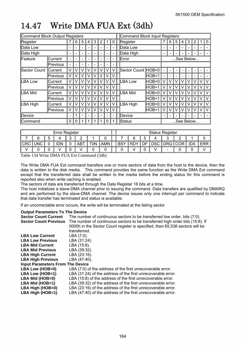
5K1500 OEM Specification
14.47 Write DMA FUA Ext (3dh) Command Block Output Registers Command Block Input Registers Register 7 6 5 4 3 2 1 0 Register 7 6 5 4 3 2 1 0Data Low - - - - - - - - Data Low - - - - - - - -Data High - - - - - - - - Data High - - - - - - - -
Current - - - - - - - - Error ...See Below... Feature Previous - - - - - - - - Current V V V V V V V V HOB=0 - - - - - - - -Sector Count Previous V V V V V V V V
Sector CountHOB=1 - - - - - - - -
Current V V V V V V V V HOB=0 V V V V V V V VLBA Low Previous V V V V V V V V
LBA Low HOB=1 V V V V V V V V
Current V V V V V V V V HOB=0 V V V V V V V VLBA Mid Previous V V V V V V V V
LBA Mid HOB=1 V V V V V V V V
Current V V V V V V V V HOB=0 V V V V V V V VLBA High Previous V V V V V V V V
LBA High HOB=1 V V V V V V V V
Device - 1 - - - - - - Device - - - - - - - -Command 0 0 1 1 1 1 0 1 Status ...See Below...
Error Register Status Register
7 6 5 4 3 2 1 0 7 6 5 4 3 2 1 0 CRC UNC 0 IDN 0 ABT T0N AMN BSY RDY DF DSC DRQ COR IDX ERR
V 0 0 V 0 V 0 0 0 V 0 V - 0 0 V
Table 134 Write DMA FUA Ext Command (3dh)
The Write DMA FUA Ext command transfers one or more sectors of data from the host to the device, then the data is written to the disk media. This command provides the same function as the Write DMA Ext command except that the transferred data shall be written to the media before the ending status for this command is reported also when write caching is enabled. The sectors of data are transferred through the Data Register 16 bits at a time. The host initializes a slave-DMA channel prior to issuing the command. Data transfers are qualified by DMARQ and are performed by the slave-DMA channel. The device issues only one interrupt per command to indicate that data transfer has terminated and status is available.
If an uncorrectable error occurs, the write will be terminated at the failing sector
Output Parameters To The Device Sector Count Current The number of continuous sectors to be transferred low order, bits (7:0). Sector Count Previous The number of continuous sectors to be transferred high order bits (15:8). If
0000h in the Sector Count register is specified, then 65,536 sectors will be transferred.
LBA Low Current LBA (7:0). LBA Low Previous LBA (31:24). LBA Mid Current LBA (15:8). LBA Mid Previous LBA (39:32). LBA High Current LBA (23:16). LBA High Previous LBA (47:40). Input Parameters From The Device LBA Low (HOB=0) LBA (7:0) of the address of the first unrecoverable error. LBA Low (HOB=1) LBA (31:24) of the address of the first unrecoverable error. LBA Mid (HOB=0) LBA (15:8) of the address of the first unrecoverable error. LBA Mid (HOB=1) LBA (39:32) of the address of the first unrecoverable error. LBA High (HOB=0) LBA (23:16) of the address of the first unrecoverable error. LBA High (HOB=1) LBA (47:40) of the address of the first unrecoverable error.
164
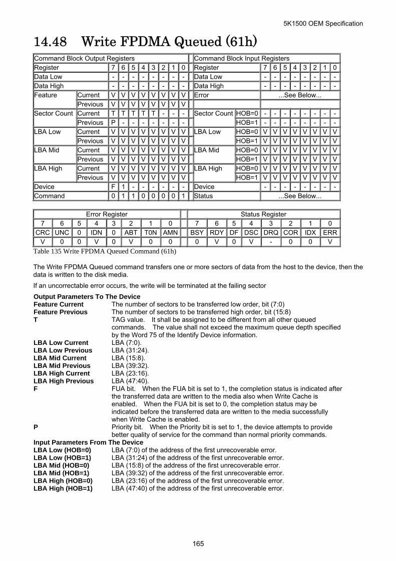
5K1500 OEM Specification
14.48 Write FPDMA Queued (61h) Command Block Output Registers Command Block Input Registers Register 7 6 5 4 3 2 1 0 Register 7 6 5 4 3 2 1 0Data Low - - - - - - - - Data Low - - - - - - - -Data High - - - - - - - - Data High - - - - - - - -
Current V V V V V V V V Error ...See Below... Feature Previous V V V V V V V V Current T T T T T - - - HOB=0 - - - - - - - -Sector Count Previous P - - - - - - -
Sector CountHOB=1 - - - - - - - -
Current V V V V V V V V HOB=0 V V V V V V V VLBA Low Previous V V V V V V V V
LBA Low HOB=1 V V V V V V V V
Current V V V V V V V V HOB=0 V V V V V V V VLBA Mid Previous V V V V V V V V
LBA Mid HOB=1 V V V V V V V V
Current V V V V V V V V HOB=0 V V V V V V V VLBA High Previous V V V V V V V V
LBA High HOB=1 V V V V V V V V
Device F 1 - - - - - - Device - - - - - - - -Command 0 1 1 0 0 0 0 1 Status ...See Below...
Error Register Status Register
7 6 5 4 3 2 1 0 7 6 5 4 3 2 1 0 CRC UNC 0 IDN 0 ABT T0N AMN BSY RDY DF DSC DRQ COR IDX ERR
V 0 0 V 0 V 0 0 0 V 0 V - 0 0 V
Table 135 Write FPDMA Queued Command (61h)
The Write FPDMA Queued command transfers one or more sectors of data from the host to the device, then the data is written to the disk media.
If an uncorrectable error occurs, the write will be terminated at the failing sector
Output Parameters To The Device Feature Current The number of sectors to be transferred low order, bit (7:0) Feature Previous The number of sectors to be transferred high order, bit (15:8) T TAG value. It shall be assigned to be different from all other queued
commands. The value shall not exceed the maximum queue depth specified by the Word 75 of the Identify Device information.
LBA Low Current LBA (7:0). LBA Low Previous LBA (31:24). LBA Mid Current LBA (15:8). LBA Mid Previous LBA (39:32). LBA High Current LBA (23:16). LBA High Previous LBA (47:40). F FUA bit. When the FUA bit is set to 1, the completion status is indicated after
the transferred data are written to the media also when Write Cache is enabled. When the FUA bit is set to 0, the completion status may be indicated before the transferred data are written to the media successfully when Write Cache is enabled.
P Priority bit. When the Priority bit is set to 1, the device attempts to provide better quality of service for the command than normal priority commands.
Input Parameters From The Device LBA Low (HOB=0) LBA (7:0) of the address of the first unrecoverable error. LBA Low (HOB=1) LBA (31:24) of the address of the first unrecoverable error. LBA Mid (HOB=0) LBA (15:8) of the address of the first unrecoverable error. LBA Mid (HOB=1) LBA (39:32) of the address of the first unrecoverable error. LBA High (HOB=0) LBA (23:16) of the address of the first unrecoverable error. LBA High (HOB=1) LBA (47:40) of the address of the first unrecoverable error.
165
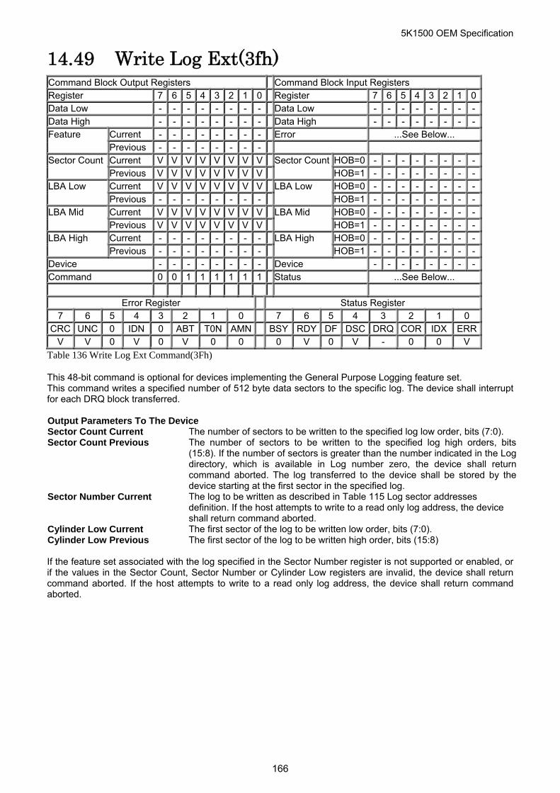
5K1500 OEM Specification
14.49 Write Log Ext(3fh) Command Block Output Registers Command Block Input Registers Register 7 6 5 4 3 2 1 0 Register 7 6 5 4 3 2 1 0Data Low - - - - - - - - Data Low - - - - - - - -Data High - - - - - - - - Data High - - - - - - - -
Current - - - - - - - - Error ...See Below... Feature Previous - - - - - - - - Current V V V V V V V V HOB=0 - - - - - - - -Sector Count Previous V V V V V V V V
Sector CountHOB=1 - - - - - - - -
Current V V V V V V V V HOB=0 - - - - - - - -LBA Low Previous - - - - - - - -
LBA Low HOB=1 - - - - - - - -
Current V V V V V V V V HOB=0 - - - - - - - -LBA Mid Previous V V V V V V V V
LBA Mid HOB=1 - - - - - - - -
Current - - - - - - - - HOB=0 - - - - - - - -LBA High Previous - - - - - - - -
LBA High HOB=1 - - - - - - - -
Device - - - - - - - - Device - - - - - - - -Command 0 0 1 1 1 1 1 1 Status ...See Below...
Error Register Status Register 7 6 5 4 3 2 1 0 7 6 5 4 3 2 1 0
CRC UNC 0 IDN 0 ABT T0N AMN BSY RDY DF DSC DRQ COR IDX ERRV V 0 V 0 V 0 0 0 V 0 V - 0 0 V
Table 136 Write Log Ext Command(3Fh)
This 48-bit command is optional for devices implementing the General Purpose Logging feature set. This command writes a specified number of 512 byte data sectors to the specific log. The device shall interrupt for each DRQ block transferred. Output Parameters To The Device Sector Count Current The number of sectors to be written to the specified log low order, bits (7:0). Sector Count Previous The number of sectors to be written to the specified log high orders, bits
(15:8). If the number of sectors is greater than the number indicated in the Logdirectory, which is available in Log number zero, the device shall return command aborted. The log transferred to the device shall be stored by thedevice starting at the first sector in the specified log.
Sector Number Current The log to be written as described in Table 115 Log sector addresses definition. If the host attempts to write to a read only log address, the device shall return command aborted.
Cylinder Low Current The first sector of the log to be written low order, bits (7:0). Cylinder Low Previous The first sector of the log to be written high order, bits (15:8)
If the feature set associated with the log specified in the Sector Number register is not supported or enabled, or if the values in the Sector Count, Sector Number or Cylinder Low registers are invalid, the device shall return command aborted. If the host attempts to write to a read only log address, the device shall return command aborted.
166
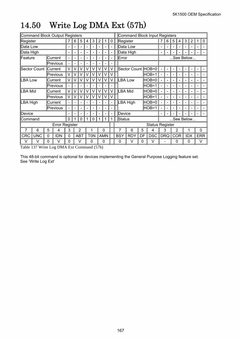
5K1500 OEM Specification
14.50 Write Log DMA Ext (57h) Command Block Output Registers Command Block Input Registers Register 7 6 5 4 3 2 1 0 Register 7 6 5 4 3 2 1 0Data Low - - - - - - - - Data Low - - - - - - - -Data High - - - - - - - - Data High - - - - - - - -
Current - - - - - - - - Error ...See Below... Feature Previous - - - - - - - - Current V V V V V V V V HOB=0 - - - - - - - -Sector Count Previous V V V V V V V V
Sector CountHOB=1 - - - - - - - -
Current V V V V V V V V HOB=0 - - - - - - - -LBA Low Previous - - - - - - - -
LBA Low HOB=1 - - - - - - - -
Current V V V V V V V V HOB=0 - - - - - - - -LBA Mid Previous V V V V V V V V
LBA Mid HOB=1 - - - - - - - -
Current - - - - - - - - HOB=0 - - - - - - - -LBA High Previous - - - - - - - -
LBA High HOB=1 - - - - - - - -
Device - - - - - - - - Device - - - - - - - -Command 0 1 0 1 0 1 1 1 Status ...See Below...
Error Register Status Register 7 6 5 4 3 2 1 0 7 6 5 4 3 2 1 0
CRC UNC 0 IDN 0 ABT T0N AMN BSY RDY DF DSC DRQ COR IDX ERRV V 0 V 0 V 0 0 0 V 0 V - 0 0 V
Table 137 Write Log DMA Ext Command (57h)
This 48-bit command is optional for devices implementing the General Purpose Logging feature set. See ‘Write Log Ext’
167
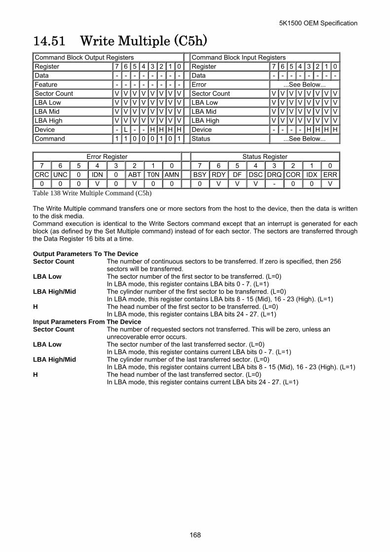
5K1500 OEM Specification
14.51 Write Multiple (C5h) Command Block Output Registers Command Block Input Registers Register 7 6 5 4 3 2 1 0 Register 7 6 5 4 3 2 1 0Data - - - - - - - - Data - - - - - - - -Feature - - - - - - - - Error ...See Below... Sector Count V V V V V V V V Sector Count V V V V V V V VLBA Low V V V V V V V V LBA Low V V V V V V V VLBA Mid V V V V V V V V LBA Mid V V V V V V V VLBA High V V V V V V V V LBA High V V V V V V V VDevice - L - - H H H H Device - - - - H H H HCommand 1 1 0 0 0 1 0 1 Status ...See Below...
Error Register Status Register
7 6 5 4 3 2 1 0 7 6 5 4 3 2 1 0 CRC UNC 0 IDN 0 ABT T0N AMN BSY RDY DF DSC DRQ COR IDX ERR
0 0 0 V 0 V 0 0 0 V V V - 0 0 V
Table 138 Write Multiple Command (C5h)
The Write Multiple command transfers one or more sectors from the host to the device, then the data is written to the disk media. Command execution is identical to the Write Sectors command except that an interrupt is generated for each block (as defined by the Set Multiple command) instead of for each sector. The sectors are transferred through the Data Register 16 bits at a time. Output Parameters To The Device Sector Count The number of continuous sectors to be transferred. If zero is specified, then 256
sectors will be transferred. LBA Low The sector number of the first sector to be transferred. (L=0)
In LBA mode, this register contains LBA bits 0 - 7. (L=1) LBA High/Mid The cylinder number of the first sector to be transferred. (L=0)
In LBA mode, this register contains LBA bits 8 - 15 (Mid), 16 - 23 (High). (L=1) H The head number of the first sector to be transferred. (L=0)
In LBA mode, this register contains LBA bits 24 - 27. (L=1) Input Parameters From The Device Sector Count The number of requested sectors not transferred. This will be zero, unless an
unrecoverable error occurs. LBA Low The sector number of the last transferred sector. (L=0)
In LBA mode, this register contains current LBA bits 0 - 7. (L=1) LBA High/Mid The cylinder number of the last transferred sector. (L=0)
In LBA mode, this register contains current LBA bits 8 - 15 (Mid), 16 - 23 (High). (L=1)H The head number of the last transferred sector. (L=0)
In LBA mode, this register contains current LBA bits 24 - 27. (L=1)
168
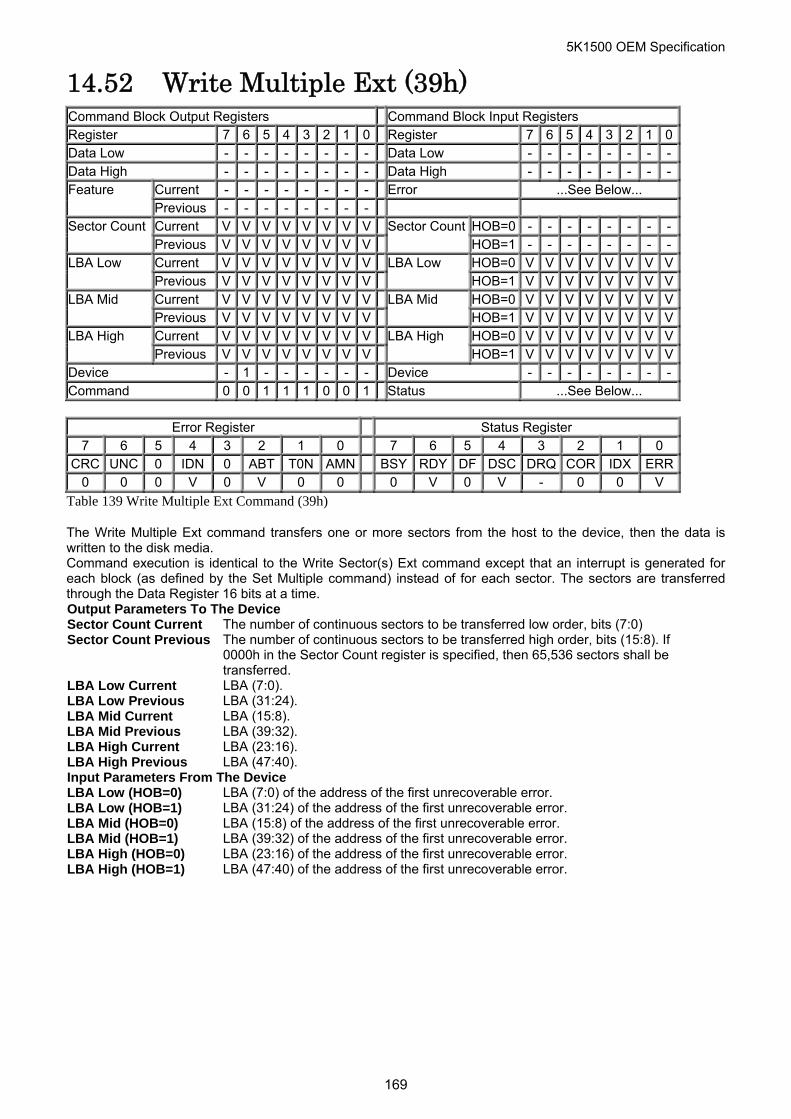
5K1500 OEM Specification
14.52 Write Multiple Ext (39h) Command Block Output Registers Command Block Input Registers Register 7 6 5 4 3 2 1 0 Register 7 6 5 4 3 2 1 0Data Low - - - - - - - - Data Low - - - - - - - -Data High - - - - - - - - Data High - - - - - - - -
Current - - - - - - - - Error ...See Below... Feature Previous - - - - - - - - Current V V V V V V V V HOB=0 - - - - - - - -Sector Count Previous V V V V V V V V
Sector CountHOB=1 - - - - - - - -
Current V V V V V V V V HOB=0 V V V V V V V VLBA Low Previous V V V V V V V V
LBA Low HOB=1 V V V V V V V V
Current V V V V V V V V HOB=0 V V V V V V V VLBA Mid Previous V V V V V V V V
LBA Mid HOB=1 V V V V V V V V
Current V V V V V V V V HOB=0 V V V V V V V VLBA High Previous V V V V V V V V
LBA High HOB=1 V V V V V V V V
Device - 1 - - - - - - Device - - - - - - - -Command 0 0 1 1 1 0 0 1 Status ...See Below...
Error Register Status Register
7 6 5 4 3 2 1 0 7 6 5 4 3 2 1 0 CRC UNC 0 IDN 0 ABT T0N AMN BSY RDY DF DSC DRQ COR IDX ERR
0 0 0 V 0 V 0 0 0 V 0 V - 0 0 V
Table 139 Write Multiple Ext Command (39h)
The Write Multiple Ext command transfers one or more sectors from the host to the device, then the data is written to the disk media. Command execution is identical to the Write Sector(s) Ext command except that an interrupt is generated for each block (as defined by the Set Multiple command) instead of for each sector. The sectors are transferred through the Data Register 16 bits at a time. Output Parameters To The Device Sector Count Current The number of continuous sectors to be transferred low order, bits (7:0) Sector Count Previous The number of continuous sectors to be transferred high order, bits (15:8). If
0000h in the Sector Count register is specified, then 65,536 sectors shall be transferred.
LBA Low Current LBA (7:0). LBA Low Previous LBA (31:24). LBA Mid Current LBA (15:8). LBA Mid Previous LBA (39:32). LBA High Current LBA (23:16). LBA High Previous LBA (47:40). Input Parameters From The Device LBA Low (HOB=0) LBA (7:0) of the address of the first unrecoverable error. LBA Low (HOB=1) LBA (31:24) of the address of the first unrecoverable error. LBA Mid (HOB=0) LBA (15:8) of the address of the first unrecoverable error. LBA Mid (HOB=1) LBA (39:32) of the address of the first unrecoverable error. LBA High (HOB=0) LBA (23:16) of the address of the first unrecoverable error. LBA High (HOB=1) LBA (47:40) of the address of the first unrecoverable error.
169
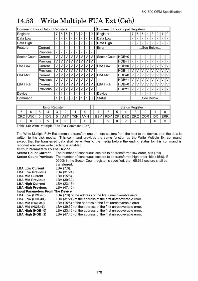
5K1500 OEM Specification
14.53 Write Multiple FUA Ext (Ceh) Command Block Output Registers Command Block Input Registers Register 7 6 5 4 3 2 1 0 Register 7 6 5 4 3 2 1 0Data Low - - - - - - - - Data Low - - - - - - - -Data High - - - - - - - - Data High - - - - - - - -
Current - - - - - - - - Error ...See Below... Feature Previous - - - - - - - - Current V V V V V V V V HOB=0 - - - - - - - -Sector Count Previous V V V V V V V V
Sector CountHOB=1 - - - - - - - -
Current V V V V V V V V HOB=0 V V V V V V V VLBA Low Previous V V V V V V V V
LBA Low HOB=1 V V V V V V V V
Current V V V V V V V V HOB=0 V V V V V V V VLBA Mid Previous V V V V V V V V
LBA Mid HOB=1 V V V V V V V V
Current V V V V V V V V HOB=0 V V V V V V V VLBA High Previous V V V V V V V V
LBA High HOB=1 V V V V V V V V
Device - 1 - - - - - - Device - - - - - - - -Command 1 1 0 0 1 1 1 0 Status ...See Below...
Error Register Status Register
7 6 5 4 3 2 1 0 7 6 5 4 3 2 1 0 CRC UNC 0 IDN 0 ABT T0N AMN BSY RDY DF DSC DRQ COR IDX ERR
0 0 0 V 0 V 0 0 0 V 0 V - 0 0 V
Table 140 Write Multiple FUA Ext Command (Ceh)
The Write Multiple FUA Ext command transfers one or more sectors from the host to the device, then the data is written to the disk media. This command provides the same function as the Write Multiple Ext command except that the transferred data shall be written to the media before the ending status for this command is reported also when write caching is enabled. Output Parameters To The Device Sector Count Current The number of continuous sectors to be transferred low order, bits (7:0) Sector Count Previous The number of continuous sectors to be transferred high order, bits (15:8). If
0000h in the Sector Count register is specified, then 65,536 sectors shall be transferred.
LBA Low Current LBA (7:0). LBA Low Previous LBA (31:24). LBA Mid Current LBA (15:8). LBA Mid Previous LBA (39:32). LBA High Current LBA (23:16). LBA High Previous LBA (47:40). Input Parameters From The Device LBA Low (HOB=0) LBA (7:0) of the address of the first unrecoverable error. LBA Low (HOB=1) LBA (31:24) of the address of the first unrecoverable error. LBA Mid (HOB=0) LBA (15:8) of the address of the first unrecoverable error. LBA Mid (HOB=1) LBA (39:32) of the address of the first unrecoverable error. LBA High (HOB=0) LBA (23:16) of the address of the first unrecoverable error. LBA High (HOB=1) LBA (47:40) of the address of the first unrecoverable error.
170
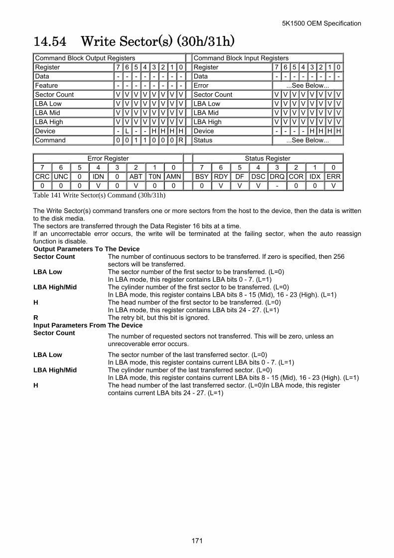
5K1500 OEM Specification
14.54 Write Sector(s) (30h/31h) Command Block Output Registers Command Block Input Registers Register 7 6 5 4 3 2 1 0 Register 7 6 5 4 3 2 1 0Data - - - - - - - - Data - - - - - - - -Feature - - - - - - - - Error ...See Below... Sector Count V V V V V V V V Sector Count V V V V V V V VLBA Low V V V V V V V V LBA Low V V V V V V V VLBA Mid V V V V V V V V LBA Mid V V V V V V V VLBA High V V V V V V V V LBA High V V V V V V V VDevice - L - - H H H H Device - - - - H H H HCommand 0 0 1 1 0 0 0 R Status ...See Below...
Error Register Status Register
7 6 5 4 3 2 1 0 7 6 5 4 3 2 1 0 CRC UNC 0 IDN 0 ABT T0N AMN BSY RDY DF DSC DRQ COR IDX ERR
0 0 0 V 0 V 0 0 0 V V V - 0 0 V
Table 141 Write Sector(s) Command (30h/31h)
The Write Sector(s) command transfers one or more sectors from the host to the device, then the data is written to the disk media. The sectors are transferred through the Data Register 16 bits at a time. If an uncorrectable error occurs, the write will be terminated at the failing sector, when the auto reassign function is disable. Output Parameters To The Device Sector Count The number of continuous sectors to be transferred. If zero is specified, then 256
sectors will be transferred. LBA Low The sector number of the first sector to be transferred. (L=0)
In LBA mode, this register contains LBA bits 0 - 7. (L=1) LBA High/Mid The cylinder number of the first sector to be transferred. (L=0)
In LBA mode, this register contains LBA bits 8 - 15 (Mid), 16 - 23 (High). (L=1) H The head number of the first sector to be transferred. (L=0)
In LBA mode, this register contains LBA bits 24 - 27. (L=1) R The retry bit, but this bit is ignored. Input Parameters From The Device Sector Count The number of requested sectors not transferred. This will be zero, unless an
unrecoverable error occurs.
LBA Low The sector number of the last transferred sector. (L=0) In LBA mode, this register contains current LBA bits 0 - 7. (L=1)
LBA High/Mid The cylinder number of the last transferred sector. (L=0) In LBA mode, this register contains current LBA bits 8 - 15 (Mid), 16 - 23 (High). (L=1)
H The head number of the last transferred sector. (L=0)In LBA mode, this register contains current LBA bits 24 - 27. (L=1)
171
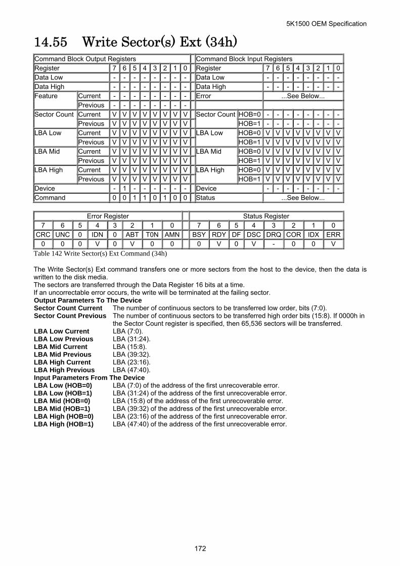
5K1500 OEM Specification
14.55 Write Sector(s) Ext (34h) Command Block Output Registers Command Block Input Registers Register 7 6 5 4 3 2 1 0 Register 7 6 5 4 3 2 1 0Data Low - - - - - - - - Data Low - - - - - - - -Data High - - - - - - - - Data High - - - - - - - -
Current - - - - - - - - Error ...See Below... Feature Previous - - - - - - - - Current V V V V V V V V HOB=0 - - - - - - - -Sector Count Previous V V V V V V V V
Sector CountHOB=1 - - - - - - - -
Current V V V V V V V V HOB=0 V V V V V V V VLBA Low Previous V V V V V V V V
LBA Low HOB=1 V V V V V V V V
Current V V V V V V V V HOB=0 V V V V V V V VLBA Mid Previous V V V V V V V V
LBA Mid HOB=1 V V V V V V V V
Current V V V V V V V V HOB=0 V V V V V V V VLBA High Previous V V V V V V V V
LBA High HOB=1 V V V V V V V V
Device - 1 - - - - - - Device - - - - - - - -Command 0 0 1 1 0 1 0 0 Status ...See Below...
Error Register Status Register 7 6 5 4 3 2 1 0 7 6 5 4 3 2 1 0
CRC UNC 0 IDN 0 ABT T0N AMN BSY RDY DF DSC DRQ COR IDX ERR0 0 0 V 0 V 0 0 0 V 0 V - 0 0 V
Table 142 Write Sector(s) Ext Command (34h)
The Write Sector(s) Ext command transfers one or more sectors from the host to the device, then the data is written to the disk media. The sectors are transferred through the Data Register 16 bits at a time. If an uncorrectable error occurs, the write will be terminated at the failing sector. Output Parameters To The Device Sector Count Current The number of continuous sectors to be transferred low order, bits (7:0). Sector Count Previous The number of continuous sectors to be transferred high order bits (15:8). If 0000h in
the Sector Count register is specified, then 65,536 sectors will be transferred. LBA Low Current LBA (7:0). LBA Low Previous LBA (31:24). LBA Mid Current LBA (15:8). LBA Mid Previous LBA (39:32). LBA High Current LBA (23:16). LBA High Previous LBA (47:40). Input Parameters From The Device LBA Low (HOB=0) LBA (7:0) of the address of the first unrecoverable error. LBA Low (HOB=1) LBA (31:24) of the address of the first unrecoverable error. LBA Mid (HOB=0) LBA (15:8) of the address of the first unrecoverable error. LBA Mid (HOB=1) LBA (39:32) of the address of the first unrecoverable error. LBA High (HOB=0) LBA (23:16) of the address of the first unrecoverable error. LBA High (HOB=1) LBA (47:40) of the address of the first unrecoverable error.
172
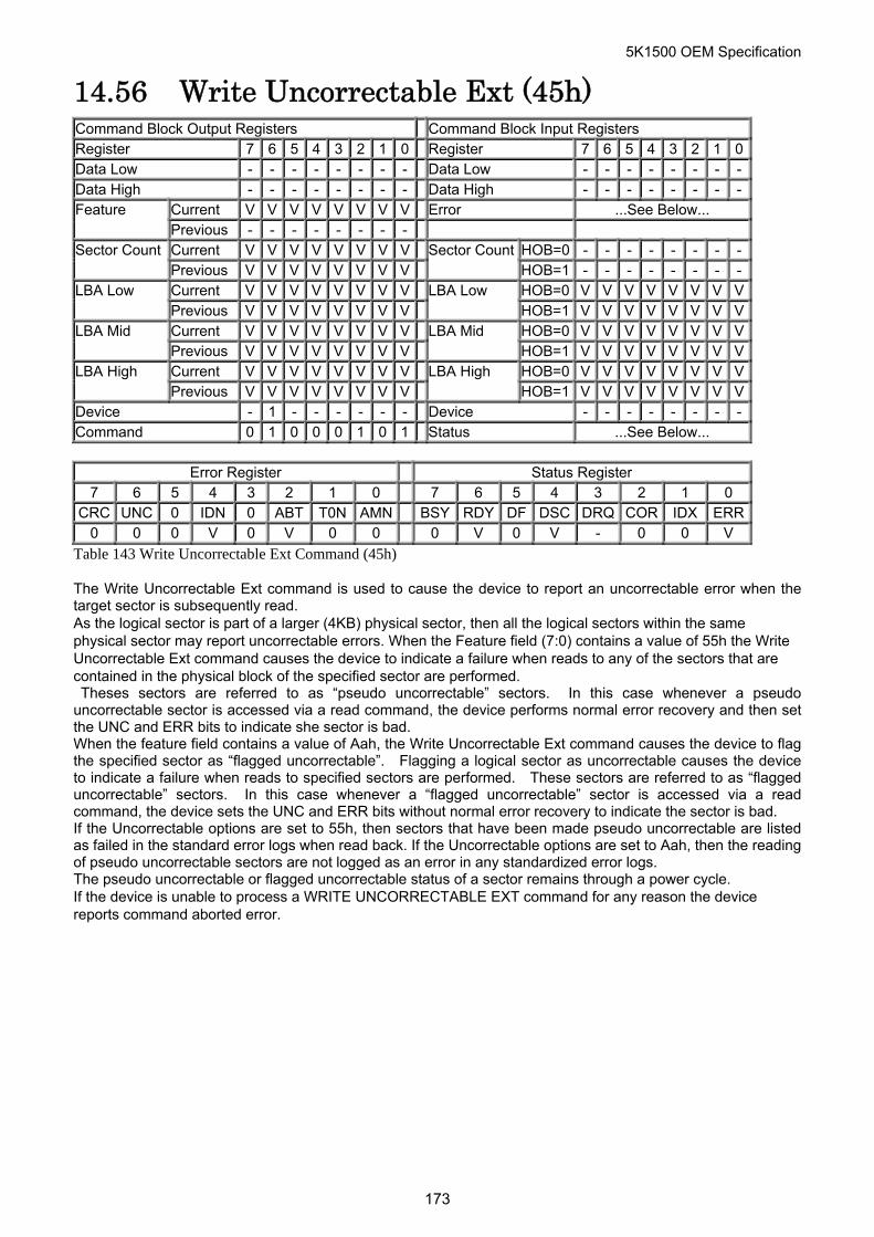
5K1500 OEM Specification
14.56 Write Uncorrectable Ext (45h) Command Block Output Registers Command Block Input Registers Register 7 6 5 4 3 2 1 0 Register 7 6 5 4 3 2 1 0Data Low - - - - - - - - Data Low - - - - - - - -Data High - - - - - - - - Data High - - - - - - - -
Current V V V V V V V V Error ...See Below... Feature Previous - - - - - - - - Current V V V V V V V V HOB=0 - - - - - - - -Sector Count Previous V V V V V V V V
Sector CountHOB=1 - - - - - - - -
Current V V V V V V V V HOB=0 V V V V V V V VLBA Low Previous V V V V V V V V
LBA Low HOB=1 V V V V V V V V
Current V V V V V V V V HOB=0 V V V V V V V VLBA Mid Previous V V V V V V V V
LBA Mid HOB=1 V V V V V V V V
Current V V V V V V V V HOB=0 V V V V V V V VLBA High Previous V V V V V V V V
LBA High HOB=1 V V V V V V V V
Device - 1 - - - - - - Device - - - - - - - -Command 0 1 0 0 0 1 0 1 Status ...See Below...
Error Register Status Register
7 6 5 4 3 2 1 0 7 6 5 4 3 2 1 0 CRC UNC 0 IDN 0 ABT T0N AMN BSY RDY DF DSC DRQ COR IDX ERR
0 0 0 V 0 V 0 0 0 V 0 V - 0 0 V
Table 143 Write Uncorrectable Ext Command (45h)
The Write Uncorrectable Ext command is used to cause the device to report an uncorrectable error when the target sector is subsequently read. As the logical sector is part of a larger (4KB) physical sector, then all the logical sectors within the same physical sector may report uncorrectable errors. When the Feature field (7:0) contains a value of 55h the Write Uncorrectable Ext command causes the device to indicate a failure when reads to any of the sectors that are contained in the physical block of the specified sector are performed. Theses sectors are referred to as “pseudo uncorrectable” sectors. In this case whenever a pseudo uncorrectable sector is accessed via a read command, the device performs normal error recovery and then set the UNC and ERR bits to indicate she sector is bad. When the feature field contains a value of Aah, the Write Uncorrectable Ext command causes the device to flag the specified sector as “flagged uncorrectable”. Flagging a logical sector as uncorrectable causes the device to indicate a failure when reads to specified sectors are performed. These sectors are referred to as “flagged uncorrectable” sectors. In this case whenever a “flagged uncorrectable” sector is accessed via a read command, the device sets the UNC and ERR bits without normal error recovery to indicate the sector is bad. If the Uncorrectable options are set to 55h, then sectors that have been made pseudo uncorrectable are listed as failed in the standard error logs when read back. If the Uncorrectable options are set to Aah, then the reading of pseudo uncorrectable sectors are not logged as an error in any standardized error logs. The pseudo uncorrectable or flagged uncorrectable status of a sector remains through a power cycle. If the device is unable to process a WRITE UNCORRECTABLE EXT command for any reason the device reports command aborted error.
173
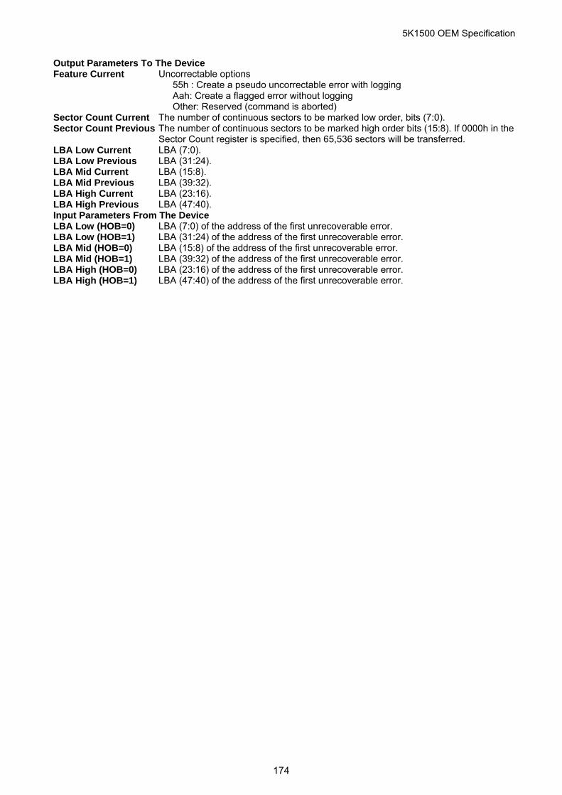
5K1500 OEM Specification
Output Parameters To The Device Feature Current Uncorrectable options
55h : Create a pseudo uncorrectable error with logging Aah: Create a flagged error without logging Other: Reserved (command is aborted)
Sector Count Current The number of continuous sectors to be marked low order, bits (7:0). Sector Count Previous The number of continuous sectors to be marked high order bits (15:8). If 0000h in the
Sector Count register is specified, then 65,536 sectors will be transferred. LBA Low Current LBA (7:0). LBA Low Previous LBA (31:24). LBA Mid Current LBA (15:8). LBA Mid Previous LBA (39:32). LBA High Current LBA (23:16). LBA High Previous LBA (47:40). Input Parameters From The Device LBA Low (HOB=0) LBA (7:0) of the address of the first unrecoverable error. LBA Low (HOB=1) LBA (31:24) of the address of the first unrecoverable error. LBA Mid (HOB=0) LBA (15:8) of the address of the first unrecoverable error. LBA Mid (HOB=1) LBA (39:32) of the address of the first unrecoverable error. LBA High (HOB=0) LBA (23:16) of the address of the first unrecoverable error. LBA High (HOB=1) LBA (47:40) of the address of the first unrecoverable error.
174
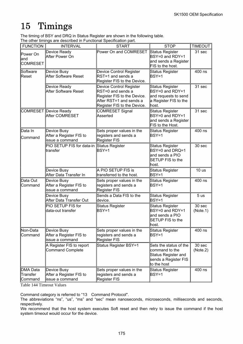
5K1500 OEM Specification
15 Timings The timing of BSY and DRQ in Status Register are shown in the following table. The other timings are described in Functional Specification part. FUNCTION INTERVAL START STOP TIMEOUT
Power On and COMRESET
Device Ready After Power On
Power On and COMRESET Status Register BSY=0 and RDY=1 and sends a Register FIS to the host.
31 sec
Device Busy After Software Reset
Device Control Register RST=1 and sends a Register FIS to the Device.
Status Register BSY=1
400 ns Software Reset
Device Ready After Software Reset
Device Control Register RST=0 and sends a Register FIS to the Device. After RST=1 and sends a Register FIS to the Device.
Status Register BSY=0 and RDY=1 and requests to send a Register FIS to the host.
31 sec
COMRESET Device Ready After COMRESET
COMRESET Signal Asserted
Status Register BSY=0 and RDY=1 and sends a Register FIS to the Host.
31 sec
Device Busy After a Register FIS to issue a command
Sets proper values in the registers and sends a Register FIS
Status Register BSY=1
400 ns
PIO SETUP FIS for data-in transfer
Status Register BSY=1
Status Register BSY=0 and DRQ=1 and sends a PIO SETUP FIS to the host.
30 sec
Data In
Command
Device Busy After Data Transfer In
A PIO SETUP FIS is transferred to the host.
Status Register BSY=1
10 us
Device Busy After a Register FIS to issue a command
Sets proper values in the registers and sends a Register FIS
Status Register BSY=1
400 ns
Device Busy After Data Transfer Out
Sends a Data FIS to the device.
Status Register BSY=1
5 us
Data Out Command
PIO SETUP FIS for data-out transfer
Status Register BSY=1
Status Register BSY=0 and RDY=1 and sends a PIO SETUP FIS to the host.
30 sec (Note.1)
Device Busy After a Register FIS to issue a command
Sets proper values in the registers and sends a Register FIS
Status Register BSY=1
400 ns Non-Data Command
A Register FIS to report Command Complete
Status Register BSY=1 Sets the status of the command to the Status Register and sends a Register FIS to the host
30 sec (Note.2)
DMA Data Transfer Command
Device Busy After a Register FIS to issue a command
Sets proper values in the registers and sends a Register FIS
Status Register BSY=1
400 ns
Table 144 Timeout Values
Command category is referred to “13 Command Protocol". The abbreviations “ns”, “us”, “ms” and “sec” mean nanoseconds, microseconds, milliseconds and seconds, respectively. We recommend that the host system executes Soft reset and then retry to issue the command if the host system timeout would occur for the device.
175
5K1500 OEM Specification
176
(Note.1) For SECURITY ERASE UNIT command, the execution time is referred to “14.30
Security Erase Unit (F4h)” on Page 129. (Note.2) FORMAT UNIT command, the execution time is referred to “14.8 Format Unit (F7h:
Vendor Specific)” on Page 89.