Embed Size (px)
Citation preview

User Guide4U60 Storage Enclosure G460-J-12February 20171ET0171Revision 1.7Long Live Data ™ | www.hgst.com
Notice
CopyrightThe following paragraph does not apply to the United Kingdom or any country where such provisionsare inconsistent with local law: HGST a Western Digital company PROVIDES THIS PUBLICATION "ASIS" WITHOUT WARRANTY OF ANY KIND, EITHER EXPRESS OR IMPLIED, INCLUDING, BUT NOTLIMITED TO, THE IMPLIED WARRANTIES OF MERCHANTABILITY OR FITNESS FOR A PARTICULARPURPOSE. Some states do not allow disclaimer or express or implied warranties in certain transactions,therefore, this statement may not apply to you.
This publication could include technical inaccuracies or typographical errors. Changes are periodically madeto the information herein; these changes will be incorporated in new editions of the publication. HGST maymake improvements or changes in any products or programs described in this publication at any time.
It is possible that this publication may contain reference to, or information about, HGST products (machinesand programs), programming, or services that are not announced in your country. Such references or informationmust not be construed to mean that HGST intends to announce such HGST products, programming, orservices in your country.
Technical information about this product is available by contacting your local HGST representative or on theInternet at: support.hgst.com
HGST may have patents or pending patent applications covering subject matter in this document. The furnishingof this document does not give you any license to these patents.
© 2017 HGST, Inc. All rights reserved.
HGST, a Western Digital company3403 Yerba Buena RoadSan Jose, CA 95135Produced in the United States
Long Live Data™ is a trademark of HGST, Inc. and its affiliates in the United States and/or other countries.
HGST trademarks are authorized for use in countries and jurisdictions in which HGST has the right to use,market and advertise the brands.
Amazon S3, Amazon Simple Storage Services, and Amazon AWS S3 are trademarks of Amazon.com, Inc.or its affiliates in the United States and/or other countries.
Other product names are trademarks or registered trademarks of their respective owners.
One MB is equal to one million bytes, one GB is equal to one billion bytes, one TB equals 1,000GB (one trillionbytes) and one PB equals 1,000TB when referring to storage capacity. Usable capacity will vary from the rawcapacity due to object storage methodologies and other factors.
References in this publication to HGST products, programs or services do not imply that HGST intends tomake these available in all countries in which HGST operates.
Product information is provided for information purposes only and does not constitute a warranty.
Information is true as of the date of publication and is subject to change. Actual results may vary. This publicationis for general guidance only. Photographs may show design models.
ii
Copyright
User Guide

Contents
Revision History..............................................................................................6
Chapter 1 Document Summary.................................................................71.1 Introduction........................................................................................7
1.2 Specification Summary......................................................................8
Chapter 2 For More Information..............................................................102.1 Points of Contact..............................................................................10
Chapter 3 Disclaimers..............................................................................113.1 Regulatory Statement......................................................................11
3.1.1 Restricted Access Location..........................................................11
3.1.2 Safety Compliance.......................................................................11
3.1.3 Electromagnetic Compatibility Agency Requirements..................12
Chapter 4 Safety.......................................................................................134.1 Optimizing Location..........................................................................13
4.2 Safety Warnings and Cautions.........................................................13
4.3 Electrostatic Discharge....................................................................13
4.4 Rackmountable Systems.................................................................14
4.5 Power Connections..........................................................................14
4.6 Power Cords.....................................................................................14
4.7 Safety and Service...........................................................................15
Chapter 5 Regulatory Statements...........................................................165.1 FCC Class A Notice.........................................................................16
5.2 FCC Verification Statement (USA)...................................................16
5.3 ICES-003 Class A Notice—Avis NMB-003, Classe A......................16
iii
Contents
User Guide

5.4 CE Notices (European Union), Class A ITE.....................................17
5.5 Europe (CE Declaration of Conformity)............................................17
5.6 Taiwan Warning Label Statement, Class A ITE...............................17
5.7 KCC Notice (Republic of Korea Only), Class A ITE.........................17
Chapter 6 Technical Specifications........................................................186.1 Rack Requirements..........................................................................18
6.2 Alternating Current Input..................................................................18
6.3 Host Connectivity.............................................................................19
6.4 Airflow Consideration.......................................................................206.4.1 Cooling the Enclosure..................................................................20
6.5 Grounding the Enclosure.................................................................206.5.1 Electrostatic Discharge.................................................................20
Chapter 7 SCSI Enclosure Services.......................................................217.1 SCSI Enclosure Services.................................................................21
Chapter 8 Enclosure Capacity................................................................228.1 Qualified Storage.............................................................................22
8.2 Enclosure Capacity..........................................................................23
8.3 Partial Population.............................................................................24
8.4 Drive On/Off Power Control..............................................................28
Chapter 9 Host and Enclosure Interconnect..........................................299.1 4U60 Storage Enclosure Interconnect.............................................29
Chapter 10 Customer Replaceable Units...............................................3210.1 Power Supply Unit..........................................................................32
10.2 Enclosure Storage Module.............................................................32
10.3 Hard Disk Drive..............................................................................33
iv
Contents
User Guide

10.3.1 Drive Carrier...............................................................................34
10.3.2 Drive Blank.................................................................................35
10.4 Cable Management Assembly.......................................................36
10.5 Power Cords...................................................................................37
10.6 HD Mini-SAS Cables......................................................................37
10.7 Expansion Cables..........................................................................37
10.8 Chassis..........................................................................................38
10.9 Rail Kit............................................................................................38
Chapter 11 Operating the 4U60 Storage Enclosure..............................3911.1 Before You Begin............................................................................39
11.2 Power On/Off..................................................................................39
11.3 Verifying the Drives........................................................................39
Chapter 12 Component and Visual Indicator Identification.................4012.1 Visual Indicator Identification.........................................................40
12.2 SCSI Enclosure Services Page 02.................................................41
v
Contents
User Guide

Revision History
CommentRevisionDate
Initial versionRevision 1.0October 2015
Updates to contentRevision 1.1December 2015
Addition of 4TB and 6TB asqualified hard disk drives
Revision 1.2December 2015
Revision 1.3February 2016 • Updates to content• Edits to content• Initial version of the
Firmware ReleaseNotes
Revision 1.4May 2016 • Added 8TB SATA and10TB SAS drives
• Edits to content
Revision 1.5August 2016 • Updated Linux upgradeinstructions
• Added Windowsupgrade instructions
• Removed 2.1.0information
• Updated documentdesign
Revision 1.6September 2016 • Updated firmwareupgrade information forESMs
• Removed 4.2.1information
Revision 1.7February 2017 • Added theInteroperability Notessection in the ReleaseNotes
• Added the SerialConsole Upgradesection in the ReleaseNotes
• Updated the SSD drivecapacity section
Note: Revision histories in the documentation set for the 4U60 Storage Enclosure refer to the docsetas a whole, not just this document.
6
Revision History
User Guide

Chapter
11 Document Summary
The following document provides information of the agency, compliance, and certifications for countries thatallow the use and operation of the 4U60 Storage Enclosure.
1.1 IntroductionThe 4U60 Storage Enclosure is a 4U, high-density drive enclosure. The enclosure is designed to house upto a full configuration of 60 drives and to maximize the performance of these drives under all operatingconditions. For a list of compatible drives consult the HGST 4U60 Hardware User Guide.
The system contains the following high level features:
Table 1: High Level Features Specifications
Number ofComponent
DetailsHardware
14U rack-mounted storage enclosure with sliderail and cable management assembly
4U60 Storage Enclosure
Up to 22U half-width SAS Expander Canister–JBODapplication (12G version)
ESM
1Drive Board • Connects the power supplies (withintegrated fans) via powerinterface board, drives, and ESM.
• Fully compliant with SAS 3.0specification for operation up to12Gbps.
60 qualifieddrives
Full Configuration: 60 drives containedwithin top accessible chassis.
3.5-inch HDD or 2.5-inch SSD
• Hot swappable• Two status LEDs per drive slot,
Activity and Fault• Ejector handle allows for easy
installation and removal of HDDsand SSDs
• With carrier
2Power Supply Unit (PSU) • 2U half-width dual 1+1 redundant,1650W AC power supplies
• 200 ~ 240 VAC (1650W) input,47Hz – 63Hz
• +12V and +5V outputs with +5Vstandby power
• 2 integrated fans powered byredundant power rail
• Compliant with 80 Plus efficiencyGold level
7
1 Document Summary
User Guide 1.1 Introduction

Number ofComponent
DetailsHardware
• +/- 5% Voltage margin control on5V and 12V rails
• Trouble history implementation• 5v and 12v DC output at 1650W
4 (2 in eachPSU)
Fans • N+1 redundant cooling• any one fan can fail and the
system will continue to operate
1.2 Specification SummaryThe following table is a summary of specs relevant and represent a fully configured enclosure:
Table 2: Specification Summary
OperatingNon-operatingCondition (Fully Configured)
5°C to 35°C-30°C to 60°CTemperature
20°C per hour5°C per hourTemperature Gradient
1°C per 125m above 950m1°C per 300m above 3000mTemperature De-rating
8% to 80% non-condensing8% to 80% non-condensingRelative Humidity
30% per hour maximum30% per hour maximumRelative Humidity Gradient
-300m to 3,048m984 ft. to 10,000 ft.
-300m to 12,000m-984 ft. to 39,370 ft.
Altitude
3.5g 6ms Pulse vertical shock8g 6ms TrapezoidalShock
Random 0.25 Grms, 5-10Hz0.05 g sine wave sweep,10-300Hz
Random 0.6 Grms 10-300HzVibration
Typical: 1.0 KVAN/APower Requirements
Max: 1.8 KVA
Maximum Enclosure Weight (full configuration—HDD): 207.6lbs./93.71 kg
Minimum Enclosure Weight (without drives): 99.6 lbs./45 kg
Weight
Dimensions (Enclosure): 174.8mm x 424mm x 871.2mm/6.88in. x16.69in. x 34.3in.
System Dimensions
Dimensions (with CMAs): 174.8mm x 424mm x 1100mm/6.88in. x16.69in. x 43.3in.
8
1 Document Summary
User Guide 1.2 Specification Summary

OperatingNon-operatingCondition (Fully Configured)
1100mm x 424mm x 174.8mm/43.3in. x 16.69in. x 6.88in.Required Rack OpeningDimensions
Note: The depth of 1100mm is required for the CMA to fit andfunction properly.
4URack Units (U)
9
1 Document Summary
User Guide 1.2 Specification Summary

Chapter
22 For More Information
The following chapter identifies the contact information for support on the 4U60 Storage Enclosure.
2.1 Points of ContactFor further assistance with an HGST product, contact HGST Data Center Solutions support. Please be preparedto provide the following information: Serial Number (S/N), product name, model number, and a brief descriptionof the issue.
Email:[email protected]
Website:www.hgst.com/4U60
Customer Technical Support and Downloads:support.hgst.com/4U60
For technical user documentation, from the bottom of the Customer Technical Support and Downloadspage, select the Resources tab.
10
2 For More Information
User Guide 2.1 Points of Contact

Chapter
33 Disclaimers
The following chapter describes the Regulatory Statement of Compliance, Safety Compliance, andElectromagnetic Compatibility Agency Requirements for the 4U60 Storage Enclosure.
3.1 Regulatory Statement
Product Name: 4U60 Storage EnclosureRegulatory Model: G460-J-12Electromagnetic Compatibility Emissions: Class A
This product has been tested and evaluated as Information Technology Equipment (ITE) at accreditedthird-party laboratories for all safety, emissions and immunity testing required for the countries and regionswhere the product is marketed and sold. The product has been verified as compliant with the latest applicablestandards, regulations and directives for those regions/countries. The suitability of this product for other productcategories other than ITE, may require further evaluation.
The product is labeled with a unique regulatory model and regulatory type that is printed on the label andaffixed to every unit. The label will provide traceability to the regulatory approvals listed in this document. Thedocument applies to any product that bears the regulatory model and type names including marketing namesother than those listed in this document.
3.1.1 Restricted Access Location
The HGST 4U60 Storage Enclosure is intended for installation in a server room or computer room where atleast one of the following conditions apply:
• access can only be gained by service persons or by users who have been instructed about the restrictionsapplied to the location and about any precautions that shall be taken and/or
• access is through the use of a tool or lock and key, or other means of security, and is controlled by theauthority responsible for the location.
3.1.2 Safety Compliance
The following table outlines how the 4U60 Storage Enclosure is designed to pass the product safetyrequirements:
Table 3: Product Safety Compliance
StatusStandardAuthority or MarkCountry/Region
CompleteAS/NZS 60950.1CB report, CB certificateAustralia/New Zealand
CompleteIEC 60950-1INMETROBrazil
CompleteCSA C22.22 No.60950-1-07
NRTLCanada/North America
CompleteTR CU 004/2011EACCustoms Union/Russia,Kazakhstan, Belarus,Armenia
CompleteEN 60950-1CEEuropean Union
11
3 Disclaimers
User Guide 3.1 Regulatory Statement

StatusStandardAuthority or MarkCountry/Region
CompleteIS 13252 (Part 1):2010BISIndia
CompleteIEC60950, CB report andCertificate to include all
International
country nationaldeviations
CompleteIEC 60950-1SIIIsrael
CompleteNOM-019-SCFI-1998NYCE or NOMMexico
CompleteSM SR EN60950-1INSMMoldova
CompleteSRPS EN60950:2010KVALITETSerbia
CompleteSANS IEC 60950-1NRCSSouth Africa
CompleteCNS14336BSMITaiwan
Complete4467-1:2005UKrTEST or equivalentUkraine
CompleteUL 60950-1NRTLUnited States/NorthAmerica
3.1.3 Electromagnetic Compatibility Agency Requirements
The following table outlines how the 4U60 Storage Enclosure is being designed to comply with theElectromagnetic Compatibility agency requirements:
Table 4: Product Electromagnetic Compatibility/Immunity Compliance
StatusStandardAuthority or MarkCountry/Region
CompleteAS/NZS CISPR22RCMAustralia/New Zealand
CompleteICES-003Industry CanadaCanada/North America
CompleteTR CU 020/2011EACCustoms Union/Russia,Kazakhstan, Belarus,Armenia
CompleteEN55022, EN55024including EN61000-3-2,EN61000-3-3
CEEuropean Union
CompleteCISPR22, CISPR24International
CompleteV-3:2014CompliantJapan
CompleteKN22, KN24MSIPKorea
CompleteCNS13438BSMITaiwan
Complete4467-1:2005UKrTEST or equivalentUkraine
CompleteFCC Part 15FCCUnited States/NorthAmerica
12
3 Disclaimers
User Guide 3.1 Regulatory Statement

Chapter
44 Safety
The following chapter provides safety and regulatory information for the 4U60 Storage Enclosure.
4.1 Optimizing LocationFailure to recognize the importance of optimally locating your product and failure to protect against electrostaticdischarge (ESD) when handling your product can result in lowered system performance or system failure.
Do not position the unit in an environment that has extreme high temperatures or extreme low temperatures.Be aware of the proximity of the unit to heaters, radiators, and air conditioners.
Position the unit so that there is adequate space around it for proper cooling and ventilation. Consult theproduct documentation for spacing information.
Keep the unit away from direct strong magnetic fields, excessive dust, and electronic/electrical equipmentthat generate electrical noise.
4.2 Safety Warnings and CautionsTo avoid personal injury or property damage, before you begin installing the product, read, observe, andadhere to all of the following safety instructions and information. The following safety symbols may be usedthroughout the documentation and may be marked on the product and/or the product packaging.
CAUTION Indicates the presence of a hazard that may cause minor personal injury or property damageif the CAUTION is ignored.
WARNING Indicates the presence of a hazard that may result in serious personal injury if the WARNINGis ignored.
Indicates potential hazard if indicated information is ignored.
Indicates shock hazards that result in serious injury or death if safety instructions are not followed.
Indicates do not touch fan blades, may result in injury.
Indicates disconnect all power sources before servicing.
4.3 Electrostatic Discharge
CAUTION
Electrostatic discharge can harm delicate components inside HGST products.
13
4 Safety
User Guide 4.1 Optimizing Location

Electrostatic discharge (ESD) is a discharge of stored static electricity that can damage equipment and impairelectrical circuitry. It occurs when electronic components are improperly handled and can result in completeor intermittent failures.
Wear an ESD wrist strap for installation, service and maintenance to prevent damage to components in theproduct. Ensure the antistatic wrist strap is attached to a chassis ground (any unpainted metal surface). Ifpossible, keep one hand on the frame when you install or remove an ESD-sensitive part.
Before moving ESD-sensitive parts place them in ESD static-protective bags until you are ready to install thepart.
4.4 Rackmountable SystemsCAUTION
Always install rack rails and storage enclosure according to 4U60 Storage Enclosure productdocumentation. Follow all cautions, warnings, labels, and instructions provided within the rackmountinstructions.
Reliable earthing of rack-mounted equipment should be maintained.
If installed in a closed or multi-unit rack assembly, the operating ambient temperature of the rack environmentmay be greater than room ambient. Therefore, consideration should be given to installing the equipment inan environment compatible with the maximum ambient temperature (Tma) specified by the manufacturer.
Observe the maximum rated ambient temperature, which is specified in the product documentation.
For safe operation of the equipment, installation of the equipment in a rack should be such that theamount of air flow is not impeded so that the safe operation of the equipment is not compromised.
4.5 Power ConnectionsBe aware of the ampere limit on any power supply or extension cables being used. The total ampere ratingbeing pulled on a circuit by all devices combined should not exceed 80% of the maximum limit for the circuit.
CAUTION The power outlet must be easily accessible close to the unit.
Always use properly grounded, unmodified electrical outlets and cables. Ensure all outlets andcables are rated to supply the proper voltage and current.
This unit has more than one power supply connection; both power cords must be removed from thepower supplies to completely remove power from the unit. There is no switch or other disconnect device.
4.6 Power Cords
Use only tested and approved power cords to connect to properly grounded power outlets or insulatedsockets of the rack's internal power supply.
If an AC power cord was not provided with your product, purchase one that is approved for use in your countryor region.
14
4 Safety
User Guide 4.4 Rackmountable Systems

CAUTION To avoid electrical shock or fire, check the power cord(s) that will be used with the product asfollows:
• The power cord must have an electrical rating that is greater than that of the electrical current rating markedon the product.
• Do not attempt to modify or use the AC power cord(s) if they are not the exact type required to fit into thegrounded electrical outlets.
• The power supply cord(s) must be plugged into socket-outlet(s) that is /are provided with a suitable earthground.
• The power supply cord(s) is / are the main disconnect device to AC power. The socket outlet(s) must benear the equipment and readily accessible for disconnection.
4.7 Safety and Service
All maintenance and service actions appropriate to the end-users are described in the productdocumentation. All other servicing should be referred to a HGST-authorized service technician.
To avoid shock hazard, turn off power to the unit by unplugging both power cords beforeservicing the unit. Use extreme caution around the chassis because potentially harmful voltages are present.
When replacing a hot-plug power supply, unplug the power cord to the power supply being replacedbefore removing it from the 4U60 Storage Enclosure.
The power supply in this product contains no user-serviceable parts. Do not open the power supply.Hazardous voltage, current and energy levels are present inside the power supply. Return to manufacturerfor servicing.
Use caution when accessing part of the product that are labeled as potential shockhazards, hazardous access to moving parts such as fan blades or caution labels.
15
4 Safety
User Guide 4.7 Safety and Service

Chapter
55 Regulatory Statements
The following chapter provides regulatory statements for the 4U60 Storage Enclosure.
HGST Storage Enclosures are marked to indicate compliance to various country and regional standards.
Note: Potential equipment damage: Operation of this equipment with cables that are not properlyshielded and not correctly grounded may cause interference to other electronic equipment and resultin violation of Class A legal requirements. Changes or modifications to this equipment that are notexpressly approved in advance by HGST will void the warranty. In addition, changes or modificationsto this equipment might cause it to create harmful interference.
5.1 FCC Class A NoticeThis device complies with Part 15 of the FCC Rules. Operation is subject to the following two conditions:
1. This device may not cause harmful interference.2. This device must accept any interference received, including interference that may cause undesired
operation.
Note: This equipment has been tested and found to comply with the limits for a Class A digital device,pursuant to Part 15 of the FCC Rules. These limits are designed to provide reasonable protectionagainst harmful interference when the equipment is operated in a commercial environment. Thisequipment generates, uses, and can radiate radio frequency energy, and if it is not installed and usedin accordance with the instruction manual, it may cause harmful interference to radio communications.Any modifications made to this device that are not approved by HGST may void the authority grantedto the user by the FCC to operate equipment.
5.2 FCC Verification Statement (USA)This device complies with Part 15 of the FCC Rules. Operation is subject to the following two conditions:
• This device may not cause harmful interference, and• this device must accept any interference received, including interference that may cause undesired operation.
Note: This equipment has been tested and found to comply with the limits for a Class A digital device,pursuant to part 15 of the FCC Rules. These limits are designed to provide reasonable protectionagainst harmful interference when the equipment is operated in a commercial environment. Thisequipment generates and can radiate radio frequency energy, and if not installed and used in accordancewith the 4U60 Storage Enclosure User Guide, it may cause harmful interference to radio communications.
5.3 ICES-003 Class A Notice—Avis NMB-003, Classe AThis Class A digital apparatus complies with Canadian ICES-003. Cet appareil numerique de la classe A estconforme à la norme NMB-003 du Canada.
16
5 Regulatory Statements
User Guide 5.1 FCC Class A Notice
5.4 CE Notices (European Union), Class A ITEMarking by the symbol indicates compliance of this system to the applicable Council Directives of the EuropeanUnion, including the Electromagnetic Compatibility Directive (2004/108/EC) and the Low Voltage Directive(2006/95/EC). A “Declaration of Conformity” in accordance with the applicable directives has been made andis on file at HGST Europe.
5.5 Europe (CE Declaration of Conformity)This digital apparatus does not exceed the Class A limits for radio noise emissions from digital apparatus setout in the interference-causing equipment standard entitled “Digital Apparatus,” ICES-003 of the CanadianDepartment of Communications.
Cet appareil numérique respecte les limites bruits radioélectriques applicables aux appareils numériques deClasse A prescrites dans la norme sur le matériel brouilleur: “Appareils Numériques”, NMB-003 édictée parle Ministre Canadian des Communications.
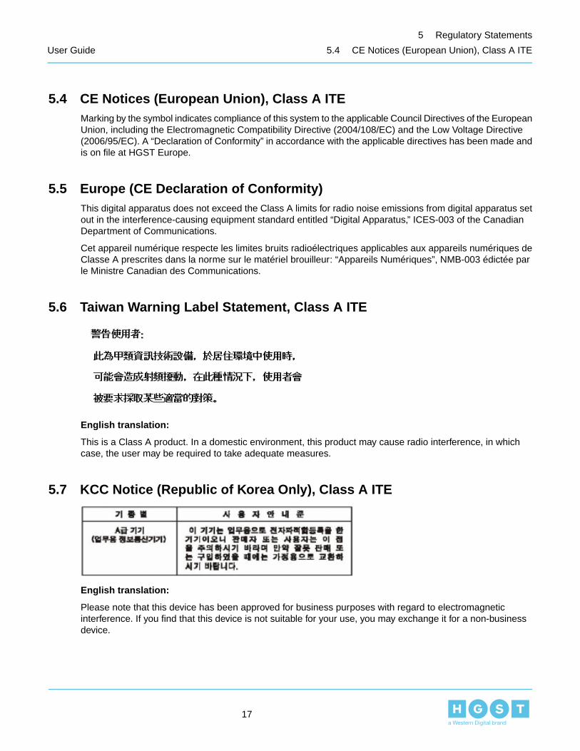
5.6 Taiwan Warning Label Statement, Class A ITE
English translation:
This is a Class A product. In a domestic environment, this product may cause radio interference, in whichcase, the user may be required to take adequate measures.
5.7 KCC Notice (Republic of Korea Only), Class A ITE
English translation:
Please note that this device has been approved for business purposes with regard to electromagneticinterference. If you find that this device is not suitable for your use, you may exchange it for a non-businessdevice.
17
5 Regulatory Statements
User Guide 5.4 CE Notices (European Union), Class A ITE
Chapter
66 Technical Specifications
The following chapter describes the technical specifications related to the 4U60 Storage Enclosure and thelocation in which it is to be installed.
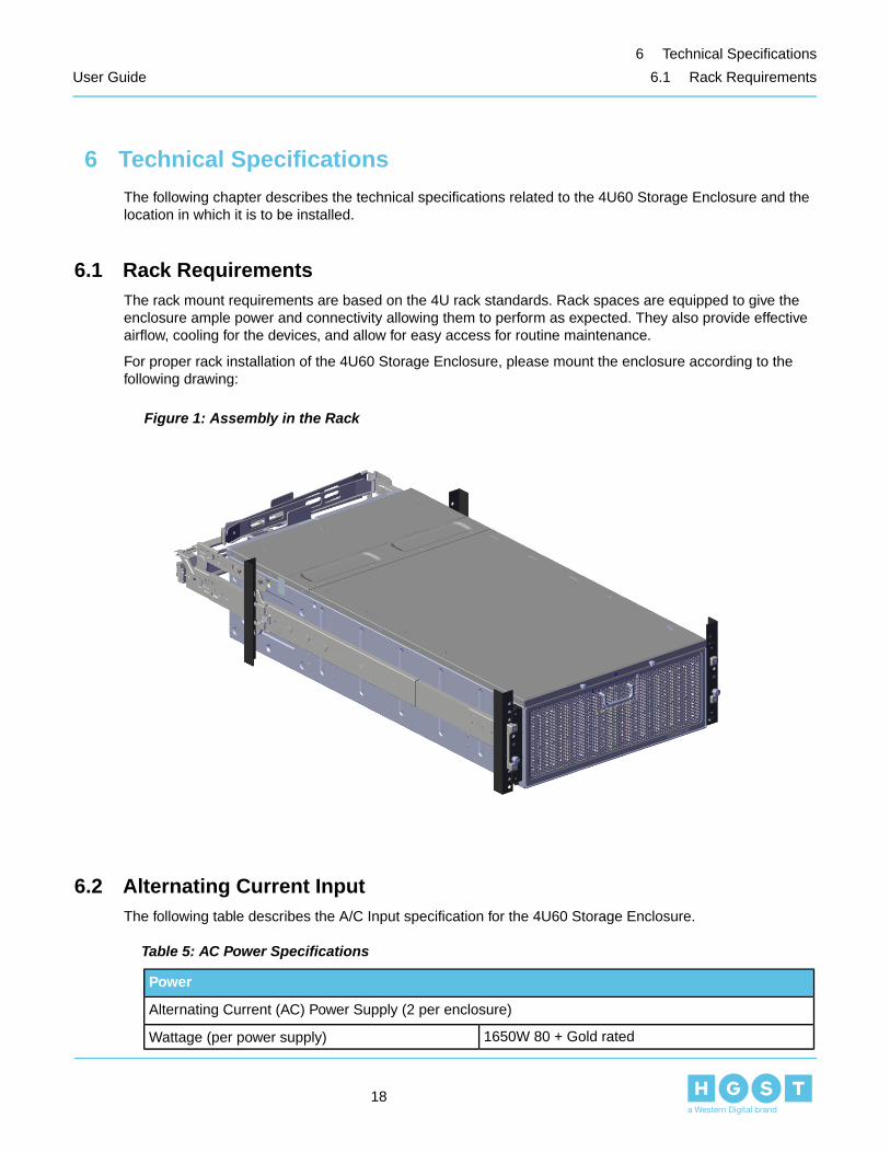
6.1 Rack RequirementsThe rack mount requirements are based on the 4U rack standards. Rack spaces are equipped to give theenclosure ample power and connectivity allowing them to perform as expected. They also provide effectiveairflow, cooling for the devices, and allow for easy access for routine maintenance.
For proper rack installation of the 4U60 Storage Enclosure, please mount the enclosure according to thefollowing drawing:
Figure 1: Assembly in the Rack
6.2 Alternating Current InputThe following table describes the A/C Input specification for the 4U60 Storage Enclosure.
Table 5: AC Power Specifications
Power
Alternating Current (AC) Power Supply (2 per enclosure)
1650W 80 + Gold ratedWattage (per power supply)
18
6 Technical Specifications
User Guide 6.1 Rack Requirements

Power
200–240VAC (1650W max), auto-ranging, 50/60 HzVoltage (per power supply)
After AC power is applied to the power supply, anyinitial inrush current surge or spike of 10 millisecondsor less must not exceed 45 amps peak.
Maximum inrush current (per power supply)
6.3 Host ConnectivityConnect the 4U60 Storage Enclosure to the host, using high quality miniSAS HD cables.
The following table displays the list of power cables approved by HGST:
Table 6: Approved Power Cables
LengthDimension (overmold)Part NumberType
1.5 metersC13 to C14BC314-BC313-1.5M-ULBIZlink Technology Inc.
1.5 metersC13 to C14R0893-C0011-01Celestica San Jose
1.5 metersC13 to C140096-0011Well Shin TechnologyCO LTD
The following table displays the list of SAS cables approved by HGST:
Table 7: Approved SAS Cables
QuantityLengthPartNumber
Type
22 metersSAS2-44361-2Elpeus HD Mini-SAS (SFF-8644) to QSFP+(SFF-8436)
22 meters1000833201Molex HD Mini-SAS (SFF-8644) to QSFP+(SFF-8436)
23 metersSAS2-44361-2Elpeus HD Mini-SAS (SFF-8644) to QSFP+(SFF-8436)
The following table displays the list of Expansion cables approved by HGST:
Table 8: Expansion Cables
QuantityLengthPartNumber
Type
22 metersCB22322-2Elpeus QSFP+(SFF-8436) to QSFP+ (SFF-8436)
22 meters1110402205Molex QSFP+(SFF-8436) to QSFP+ (SFF-8436)
23 MetersCB22322-2Elpeus QSFP+(SFF-8436) to QSFP+ (SFF-8436)
19
6 Technical Specifications
User Guide 6.3 Host Connectivity

6.4 Airflow ConsiderationThe user needs to ensure both the front and rear of the 4U60 Storage Enclosure stay clear of any materialsthat may block or disrupt the airflow in any way. Disrupting the airflow can cause the enclosure to run the fansat an excessive RPM.
The following rack airflow principles should be considered for best results:
• Controlled air conditioners that are located in the facility where the enclosure will be installed.• The airflow in and out of the equipment must not be restricted.
6.4.1 Cooling the Enclosure
The 4U60 Storage Enclosure has an advanced thermal algorithm that monitors all of the temperature sensorsin the system. The enclosure makes adjustments to the fan speeds based upon the thermal sensors. The fanalgorithm takes into account for the temperature sensor warning and critical threshold limits set by SES. Ifany temperature sensor gets to the warning limit, the fans speeds will increase to cool the component. If theenclosure encounters low temperatures, the system will reduce fan speed in an attempt to conserve powerand not over-cool the enclosure.
This algorithm is agnostic to effects of altitude and humidity. The algorithm simply works based on temperatureswithin the system with emphasis on reducing power consumption.
6.5 Grounding the EnclosureThe enclosure is designed to ground all components to the chassis base with the use of a properly groundedreceptacle. Ensure that there is sufficient electrical and mechanical connection from the chassis base to therack rails, and that the rack itself is tied to earth ground.
The unit must be grounded in accordance with all local/regional and national electrical codes.
6.5.1 Electrostatic Discharge
The enclosure is designed to dissipate all electrostatic discharges to the chassis base. Ensure that there issufficient electrical and mechanical connection from the chassis base to the rack rails, and that the rack itselfis tied to earth ground. It is recommend that suitable ESD precautions be observed during installation andservice operations
20
6 Technical Specifications
User Guide 6.4 Airflow Consideration

Chapter
77 SCSI Enclosure Services
The following chapter describes the overall functionality of SES within the 4U60 Storage Enclosure.
7.1 SCSI Enclosure ServicesThe 4U60 Storage Enclosure provides enclosure management capabilities in-band through the MiniSAS HDports using the SCSI Enclosure Services 3 (SES-3). The management functions are performed with SCSIcommands, which are targeted at the Input/Ouput controller’s embedded SCSI Enclosure Processor (SEP)device. The 4U60 Storage Enclosure SES command set allows management clients to observe and controlthe functionality of the enclosure itself, as well as various management entities associated with the enclosure,including the embedded controller, disk drives, power supplies, fans, and connectors.
21
7 SCSI Enclosure Services
User Guide 7.1 SCSI Enclosure Services

Chapter
88 Enclosure Capacity
The following chapter describes defines the capacity of the enclosure and the qualified hard drives for the4U60 Storage Enclosure.
8.1 Qualified StorageThe SEP examines the Inquiry data of all attached drives to determine if they are a supported type. If anunsupported device is attached to the 4U60 Storage Enclosure, it will not be available to access.
The enclosure uses the following qualified hard disk drives (HDDs):
Table 9: Qualified Hard Disk Drives
ModelForm FactorFormatFamilyCapacity
HUS726040AL52143.5in.SAS 512e SEUltrastar 7K60004TB
HUS726040AL52103.5in.SAS 512e ISEUltrastar 7K60004TB
HUS726040AL42143.5in.SAS 4Kn SEUltrastar 7K60004TB
HUS726040AL42103.5in.SAS 4Kn ISEUltrastar 7K60004TB
HUS726040AL52113.5in.SAS 512e TCGUltrastar 7K60004TB
HUS726060AL52143.5in.SAS 512e SEUltrastar 7K60006TB
HUS726060AL52103.5in.SAS 512e ISEUltrastar 7K60006TB
HUS726060AL42143.5in.SAS 4Kn SEUltrastar 7K60006TB
HUS726060AL42103.5in.SAS 4Kn ISEUltrastar 7K60006TB
HUS726060AL52113.5in.SAS 512e TCGUltrastar 7K60006TB
HUH728080AL52043.5in.SAS 512e SEUltrastar He88TB
HUH728080AL42043.5in.SAS 4Kn SEUltrastar He88TB
HUH728080AL52003.5in.SAS 512e ISEUltrastar He88TB
HUH728080AL42003.5in.SAS 4Kn ISEUltrastar He88TB
HUH728080AL52013.5in.SAS 4Kn TCGUltrastar He88TB
HUH728080ALE6003.5in.SATA 512e ISEUltrastar He88TB
HUH728080ALE6043.5in.SATA 512e SEUltrastar He88TB
HUH728080ALE6013.5in.SATA 512e BDEUltrastar He88TB
HUH728080ALN6003.5in.SATA 4Kn ISEUltrastar He88TB
HUH728080ALN6043.5in.SATA 4Kn SEUltrastar He88TB
HUH728080ALN6013.5in.SATA 4Kn BDEUltrastar He88TB
HUH721010AL52003.5in.SAS 512e ISEUltrastar He1010TB
22
8 Enclosure Capacity
User Guide 8.1 Qualified Storage

ModelForm FactorFormatFamilyCapacity
HUH721010AL52013.5in.SAS 512e TCGUltrastar He1010TB
HUH721010AL52043.5in.SAS 512e SEUltrastar He1010TB
HUH721010AL42003.5in.SAS 4Kn ISEUltrastar He1010TB
HUH721010AL42013.5in.SAS 4Kn TCGUltrastar He1010TB
HUH721010AL42043.5in.SAS 4Kn SEUltrastar He1010TB
HUH721010ALE6003.5in.SATA 512e ISEUltrastar He1010TB
HUH721010ALE6043.5in.SATA 512e SEUltrastar He1010TB
HUH721010ALE6013.5in.SATA 512e SED(BDE + TCG)
Ultrastar He1010TB
The enclosure uses the following qualified solid state drives (SSDs):
Table 10: Qualified Solid State Disk Drives
ModelForm FactorFormatFamilyCapacity
SDLTODKM-400G-5CA12.5in.SAS ISESanDisk LightningAscend Gen. II
400GB
SDLF1DAM-800G-1HA12.5in.SATA SESanDiskCloudSpeed UltraGen. II
800GB
8.2 Enclosure CapacityThe following section lists the capacity options per enclosure. The HDD options for capacity consider 4TB,6TB, 8TB, and 10TB, with up to 60 HDDs per enclosure. The SSD options for capacity consider 200GB and400GB, with up to 12 SSDs per enclosure.
Table 11: Enclosure Capacity
FamilyCapacity per Hard DiskDrive
Max Drives PerEnclosure
Raw capacity perEnclosure
Ultrastar 7K60004TB (SAS)60240TB
Ultrastar 7K60006TB (SAS)60360TB
Ultrastar He88TB (SAS and SATA)60480TB
Ultrastar He1010TB (SAS)60600TB
Ultrastar He1010TB (SATA)60600TB
Ultrastar SSD800MH.B200GB (SAS)122.4TB
Ultrastar SSD1600MR400GB (SAS)124.8TB
23
8 Enclosure Capacity
User Guide 8.2 Enclosure Capacity

8.3 Partial PopulationThe 4U60 Storage Enclosure allows for partial population of the enclosure.
SSD Partial Population Rules
The following population rules for SSDs must be followed for a partially populated enclosure to functionproperly:
• The minimum amount of drives required for the enclosure to function properly is two SSDs.• Each increase in drive must be done in increments of two.• Each row that is partially populated with drives (HDD and/or SSD) must have the population of that row
completed with blanks.• A combination of HDDs and SSDs are allowed, but the rule of increasing capacity must be done by two
when SSDs are involved.• The remainder of the enclosure, preceding a populated row may remain empty.• When SSDs are involved, the population of drive slots must be done in the order and positions
displayed below.• Repeat the configuration for each following row.
24
8 Enclosure Capacity
User Guide 8.3 Partial Population

The following diagrams display the partially populated configurations for the first row of drives:
Figure 2: Partially Populated Configurations
25
8 Enclosure Capacity
User Guide 8.3 Partial Population

00 01 02 03 04 05 06 07 08 09 10 11
12 13 14 15 16 17 18 19 20 21 22 23
24 25 26 27 28 29 30 31 32 33 34 35
48 49 50 51 52 55 56 57 58 59
DRIVE LOCATION
53 5454
36 37 38 39 40 41 42 43 44 45 46 47
00 01 02 03 04 05 06 07 08 09 10 11
12 13 14 15 16 17 18 19 20 21 22 23
24 26 27 28 29 30 31 32 33 34 35
48 49 50 51 56 57 58 59
POWER SUPPLY
53 5454
37 38 39 40 41 42 43 44 45 46 47
52
25
36
00 01 02 03 04 05 06 07 08 09 10 11
12 13 14 15 16 17 18 19 20 21 22 23
24 26 27 28 29 30 31 32 33 34 35
53 5454
25
51504948 56 57 58 59
37 38 39 40 41 42 43 44 45 46 4736
Power Supply Power Supply
52 55
00 01 02 03 04 05 06 07 08 09 10 11
12 13 14 15 16 17 18 19 20 21 22 23
24 26 27 28 29 30 31 32 33 34 35
48 49 50 51 56 57 58 59
POWER SUPPLY
53 5454
37 38 39 40 41 42 43 44 45 46 47
5552
25
36
00 01 02 03 04 05 06 07 08 09 10 11
12 13 14 15 16 17 18 19 20 21 22 23
24 26 27 28 29 30 31 32 33 34 35
53 5454 5552
25
51504948 56 57 58 59
37 38 39 40 41 42 43 44 45 46 4736
Power Supply Power Supply
00 01 02 03 04 05 06 07 08 09 10 11
12 13 14 15 16 17 18 19 20 21 22 23
24 26 27 28 29 30 31 32 33 34 35
53 5454 5552
25
504948 57 58 59
37 38 39 40 41 42 43 44 45 46 4736
Power Supply Power Supply
51 56
Populated with a Drive
Populated with a Blank
Unpopulated Drive Slot
26
8 Enclosure Capacity
User Guide 8.3 Partial Population

00 01 02 03 04 05 06 07 08 09 10 11
12 13 14 15 16 17 18 19 20 21 22 23
24 26 27 28 29 30 31 32 33 34 35
53 5454 5552
25
4948 58 59
37 38 39 40 41 42 43 44 45 46 4736
Power Supply Power Supply
51 5650 57
00 01 02 03 04 05 06 07 08 09 10 11
12 13 14 15 16 17 18 19 20 21 22 23
24 26 27 28 29 30 31 32 33 34 35
53 5454 5552
25
48 59
37 38 39 40 41 42 43 44 45 46 4736
Power Supply Power Supply
51 5650 57 5849
00 01 02 03 04 05 06 07 08 09 10 11
12 13 14 15 16 17 18 19 20 21 22 23
24 26 27 28 29 30 31 32 33 34 35
53 5454 5552
25
37 38 39 40 41 42 43 44 45 46 4736
Power Supply Power Supply
51 5650 57 5849 5948
Populated with a Drive
Populated with a Blank
Unpopulated Drive Slot
HDD Partial Population Rules
27
8 Enclosure Capacity
User Guide 8.3 Partial Population

The following population rules for HDDs must be followed for a partially populated enclosure to functionproperly:
• The minimum amount of drives required for the enclosure to function properly is one HDD.• Each row that is partially populated with drives must have the population of that row completed with blanks.
Note: The position of the HDD does not matter as long as the remaining slots in that row have beenpopulated with blanks.
• The remainder of the enclosure, preceding a populated row may remain empty.• Repeat the configuration for each following row.
8.4 Drive On/Off Power ControlThe 4U60 Storage Enclosure supports individual drive power control utilizing the T10 Pin 3 Power Disable.
The following requirements must be met in order for the power control feature to function properly:
• HDD must support T10 Pin 3 Power Disable• 4U60 Storage Enclosure drive board model number must be R0814-G0004-03 (old) and R0814-G0004-04
(new)• Firmware Version: 4.2.5
28
8 Enclosure Capacity
User Guide 8.4 Drive On/Off Power Control

Chapter
99 Host and Enclosure Interconnect
The following section describes the interconnect from the hosts to an enclosure or enclosures.
9.1 4U60 Storage Enclosure InterconnectThe following rules for interconnecting or daisy chaining 4U60 Storage Enclosures must be followed for a thefor proper functionality:
• The maximum amount of 4U60 Storage Enclosures that can be connected together is four.• The hosts must connect to the IN port on their respective sides.
29
9 Host and Enclosure Interconnect
User Guide 9.1 4U60 Storage Enclosure Interconnect

The following figure displays the proper connection for interconnecting multiple enclosures:
Figure 3: Daisy Chain
30
9 Host and Enclosure Interconnect
User Guide 9.1 4U60 Storage Enclosure Interconnect

31
9 Host and Enclosure Interconnect
User Guide 9.1 4U60 Storage Enclosure Interconnect

Chapter
1010 Customer Replaceable Units
The following chapter describes the Customer Replaceable Units for the 4U60 Storage Enclosure.
Note: Refer to the Customer Replaceable Unit Guide for detailed instructions on how to replace customerreplaceable units.
10.1 Power Supply UnitThe 4U60 Storage Enclosure contains two redundant power supply units (PSU).
Note: The PSU is a hot swappablecomponent.
Figure 4: Power Supply Unit
10.2 Enclosure Storage ModuleThe 4U60 Storage Enclosure contains two Enclosure Storage Modules (ESM) as a standard for SAS driveconfigurations. The 4U60 Storage Enclosure contains one ESM for SATA drive configurations. The singleESM configuration replaces one of the ESMs with a blank to ensure proper airflow within the enclosure.
32
10 Customer Replaceable Units
User Guide 10.1 Power Supply Unit

Note: The ESM is a hot swappablecomponent.
Figure 5: Enclosure Storage Module
10.3 Hard Disk DriveThe full configuration of the 4U60 Storage Enclosure contains 60 qualified drives. If the enclosure is partiallypopulated, any row that contains drives must be completed with drive slot blanks. Drive slot blanks look likea plastic version of a real drive and help keep proper airflow throughout the enclosure.
33
10 Customer Replaceable Units
User Guide 10.3 Hard Disk Drive

Note: The HDDs are hot swappablecomponents.
Figure 6: Hard Disk Drive
For a list of qualified hard drives, see Qualified Storage on page 22.
10.3.1 Drive Carrier
The 4U60 Storage Enclosure contains 60 drive carriers.
34
10 Customer Replaceable Units
User Guide 10.3 Hard Disk Drive

Note: The drive carriers are hot swappablecomponents.
Figure 7: Drive Carrier
10.3.2 Drive Blank
The 4U60 Storage Enclosure is designed to accept drive blanks to complete the population of drive rows andmaintain proper airflow within the enclosure.
35
10 Customer Replaceable Units
User Guide 10.3 Hard Disk Drive

Note: The drive blanks are hot swappablecomponents.
Figure 8: Drive Blank
10.4 Cable Management AssemblyThe 4U60 Storage Enclosure contains a cable management assembly (CMA) that includes an upper andlower arm.
36
10 Customer Replaceable Units
User Guide 10.4 Cable Management Assembly

Note: The CMA is designed to cable the enclosure to meet the needs of your specificconfiguration.
Figure 9: Cable Management Assembly
10.5 Power CordsThe 4U60 Storage Enclosure contains a power cord for each of the two PSUs.
Note: It is highly recommended that you use the power cords that have been approved for this particularenclosure. For a list of approved power cords, see: Host Connectivity on page 19.
10.6 HD Mini-SAS CablesThe 4U60 Storage Enclosure contains an HD Mini-SAS cable for each of the two ESMs.
Note: It is highly recommended that you use the HD Mini-SAS cables that have been approved for thisparticular enclosure. For a list of approved HD Mini-SAS cables, see: Host Connectivity on page 19.
10.7 Expansion CablesThe 4U60 Storage Enclosure has the option to utilize expansion cables to allow for the connection of up tofour enclosures.
Note: It is highly recommended that you use the Expansion cables that have been approved for thisparticular enclosure. For a list of approved expansion cables, see: Host Connectivity on page 19.
37
10 Customer Replaceable Units
User Guide 10.5 Power Cords

The OUT expansion port may be utilized for a additional bandwidth in the event that the 4U60 StorageEnclosures are not being connected to each other.
10.8 ChassisThe 4U60 Storage Enclosure chassis houses the all of the components that allow for the enclosure to function.During the chassis replacement, it is highly recommended that you remove and store the functioningcomponents in a safe place.
Figure 10: Chassis
10.9 Rail KitThe 4U60 Storage Enclosure is installed into the rack using a rail kit. The rail kit is designed to clip into therack before attaching it with screws. This allows for ease of installation and adjustment. The chassis and allother component will need to be removed in order to replace the component.
Figure 11: Rail Kit
38
10 Customer Replaceable Units
User Guide 10.8 Chassis

Chapter
1111 Operating the 4U60 Storage Enclosure
The following chapter describes the operation of the 4U60 Storage Enclosure.
11.1 Before You BeginEnsure that you have all of proper cabling to connect to the enclosure. The enclosure is designed to be installedinto a rack, not assembled on a bench top. Connect all of the cables, and turn on and boot the host or controlnode server. Connect the power to the 4U60 Storage Enclosure; it will come on and boot without any interactionfrom the user.
11.2 Power On/OffThe 4U60 Storage Enclosure does not have an external power switch, the enclosure is powered on by pluggingpower cords into the power supplies. Once powered on, the enclosure automatically powers up all drives.
11.3 Verifying the DrivesTo verify the drives, do the following:
1. Using SG Utilities, type the following command Sg_scan –a -s -v.A list of device SCSI results appear.
2. Press Enter.
39
11 Operating the 4U60 Storage Enclosure
User Guide 11.1 Before You Begin

Chapter
1212 Component and Visual Indicator Identification
The following chapter describes the component and visual indicator identification.
12.1 Visual Indicator IdentificationThe 4U60 Storage Enclosure contains the following LEDs:
Table 12: 4U60 Storage Enclosure LED Descriptions
LED ActionLED Name
ESM
Power • Green: ESM powered on.• Off: ESM powered off.
Fault • Red: ESM has one or more faults.• Off: ESM has no faults.
Locate • Blinking Amber: ESM is being identified.• Off: ESM is not being identified.
SAS Link Up • Green: SAS link has an activeconnection.
• Off: SAS link does not have an activeconnection.
Enclosure
Locate • Blinking Amber: Enclosure is beingidentified.
• Off: Enclosure is not being identified.
Power • Green: Enclosure is powered on.• Off: Enclosure is powered off.
Ready • Green: Enclosure is ready.• Off: Enclosure is not ready.
PSU
Fault • Red: PSU has one or more faults.• Blinking Red: PSU is being identified.• Off: PSU has no faults.
Ready • Green: PSU is powered on.• Off: PSU is powered off.
ACIN • Green: AC input OK.• Off: No AC input.
40
12 Component and Visual Indicator Identification
User Guide 12.1 Visual Indicator Identification
LED ActionLED Name
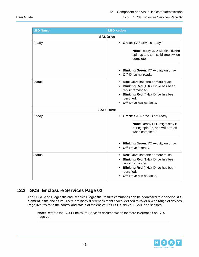
SAS Drive
Ready • Green: SAS drive is ready
Note: Ready LED will blink duringspin-up and turn solid green whencomplete.
• Blinking Green: I/O Activity on drive.• Off: Drive not ready.
Status • Red: Drive has one or more faults.• Blinking Red (1Hz): Drive has been
rebuilt/remapped.• Blinking Red (4Hz): Drive has been
identified.• Off: Drive has no faults.
SATA Drive
Ready • Green: SATA drive is not ready.
Note: Ready LED might stay litduring spin-up, and will turn offwhen complete.
• Blinking Green: I/O Activity on drive.• Off: Drive is ready.
Status • Red: Drive has one or more faults.• Blinking Red (1Hz): Drive has been
rebuilt/remapped.• Blinking Red (4Hz): Drive has been
identified.• Off: Drive has no faults.
12.2 SCSI Enclosure Services Page 02The SCSI Send Diagnostic and Receive Diagnostic Results commands can be addressed to a specific SESelement in the enclosure. There are many different element codes, defined to cover a wide range of devices.Page 02h refers to the control and status of the enclosures PSUs, drives, ESMs, and sensors.
Note: Refer to the SCSI Enclosure Services documentation for more information on SESPage 02.
41
12 Component and Visual Indicator Identification
User Guide 12.2 SCSI Enclosure Services Page 02

Index
A
AC 18input 18airflow 20consideration 20
B
before you begin 39
C
CE 17notice 17
european union 17class a ITE 17
chassis 38CMA 36component 40
visual indicator 40identification 40
control 28cooling 20enclosure 20copyright ii
D
disclaimer 11document 7summary 7drive 28, 34–35carrier 34–35
E
electromagnetic 12compatibility 12agency 12requirements 12
electrostatic 13, 20discharge 13, 20enclosure 22–23, 29capacity 22–23connection 29
ESM 32expansion 37cable 37
F
FCC 16class a 16notice 16verification 16
statement 16USA 16
field 32replaceable 32unit 32
for more information 10
G
grounding 20enclosure 20
H
hd 37mini-sas 37cable 37
HDD 33host 19, 29connectivity 19
enclosure 29interconnect 29
I
ICES-003 16–17Canada 17
class a 16notice 16
Avis NMB-003 16classe a 16
introduction 7
42
Index
User Guide

K
KCC 17notice 17
republic of Korea 17class a ITE 17
L
location 13optimizing 13
N
notice ii
O
on/off 28operating 39enclosure 39optimizing 13location 13optimizing location 13
P
points of contact 10power 14, 28, 37, 39connection 14cord 14, 37
on 39off 39
PSU 32
Q
qualified 22storage 22
R
rack 18requirements 18
rackmount 14system 14rail kit 38regulatory 11, 16
statement 11, 16compliance 11
restricted 11access 11location 11
revision history 6
S
safety 11, 13, 15compliance 11service 15
warning 13caution 13
SES 21, 41page 02 41specification 8summary 8ssd 24
partial 24population 24
T
Taiwan 17warning label 17
statement 17class a ITE 17
technical 18specification 18
V
verifying 39drives 39visual indicator 40identification 40
43
Index
User Guide