Embed Size (px)
Citation preview

• • o
• • D
SPENT FUEL REPROCESSING
PLANT
WASTE EVAPORATOR
i
WASTE STORAGE TANK
WASTE~T SOLIDIFICATION
Q U
UNDERGROUND DISPOSAL
T E C H N I C A L R E P O R T S S E R I E S No 191
Handling and Storage of High-Level Radioactive
Liquid Wastes Requiring Cooling
íS?í INTERNATIONAL A T O M I C ENERGY A G E N C Y , V I E N N A , 1979 ¿y


HANDLING AND STORAGE OF HIGH-LEVEL RADIOACTIVE
LIQUID WASTES REQUIRING COOLING

The following States are Members of the Internat ional Atomic Energy Agency:
AFGHANISTAN ALBANIA ALGERIA A R G E N T I N A AUSTRALIA AUSTRIA BANGLADESH BELGIUM BOLIVIA BRAZIL BULGARIA BURMA BYELORUSSIAN SOVIET
SOCIALIST REPUBLIC CANADA CHILE COLOMBIA COSTA RICA CUBA CYPRUS
CZECHOSLOVAKIA DEMOCRATIC KAMPUCHEA DEMOCRATIC PEOPLE'S
REPUBLIC O F K O R E A DENMARK DOMINICAN REPUBLIC ECUADOR EGYPT EL SALVADOR ETHIOPIA F I N L A N D F R A N C E GABON GERMAN DEMOCRATIC REPUBLIC GERMANY, F E D E R A L REPUBLIC O F GHANA G R E E C E GUATEMALA HAITI
HOLY SEE HUNGARY ICELAND INDIA INDONESIA IRÁN IRAQ IRELAND ISRAEL ITALY IVORY COAST JAMAICA JAPAN J O R D A N KENYA KOREA, REPUBLIC O F KUWAIT LEBANON LIBERIA LIBYAN ARAB JAMAHIRIYA LIECHTENSTEIN LUXEMBOURG MADAGASCAR MALAYSIA MALI MAURITIUS MEXICO MONACO MONGOLIA MOROCCO N E T H E R L A N D S NEW ZEALAND NICARAGUA NIGER NIGERIA NORWAY PAKISTAN PANAMA PARAGUAY PERU
PHILIPPINES POLAND P O R T U G A L Q A T A R ROMANIA SMJDI ARABIA SENEGAL SIERRA LEONE S I N G A P O R E SOUTH AFRICA SPAIN SRI LANKA SUDAN SWEDEN SWITZERLAND SYRIAN ARAB REPUBLIC T H A I L A N D TUNISIA T U R K E Y UGANDA UKRAINIAN SOVIET SOCIALIST
REPUBLIC UNION O F SOVIET SOCIALIST
REPUBLICS UNITED ARAB EMIRATES UNITED KINGDOM O F G R E A T
BRITAIN AND N O R T H E R N I R E L A N D
UNITED REPUBLIC O F CAMEROON
UNITED REPUBLIC O F T A N Z A N I A
UNITED STATES O F AMERICA URUGUAY VENEZUELA VIET NAM YUGOSLAVIA Z A I R E ZAMBIA
The Agency's S ta tu te was approved on 23 October 1956 by the Conference on the S t a tu t e of the IAEA held at United Nations Headquarters , New York ; it entered in to force on 29 July 1957. The Headquar ters of the Agency are s i tuated in Vienna. Its principal objective is " to accelerate and enlarge the con t r ibu t ion of atomic energy to peace, health and prosperi ty throughout the world".
( ç ) IAEA, 1979
Permission to reproduce or translate the informat ion conta ined in this publicat ion may be obta ined by writing t o the In ternat ional Atomic Energy Agency, Kärn tner Ring 11, P.O. Box 590, A-1011 Vienna, Austria.
Printed by the IAEA in Austria March 1979

TECHNICAL REPORTS SERIES No. 191
HANDLING AND STORAGE OF HIGH-LEVEL RADIOACTIVE
LIQUID WASTES REQUIRING COOLING
INTERNATIONAL ATOMIC ENERGY AGENCY VIENNA, 1979

HANDLING AND STORAGE OF HIGH-LEVEL RADIOACTIVE LIQUID WASTES REQUIRING COOLING
IAEA, VIENNA, 1979 STI/DOC/10/191
ISBN 9 2 - 0 - 1 2 5 4 7 9 - 2

FOREWORD
The high-level fission-product solutions resulting from the reprocessing of irradiated nuclear fuels are at present being concentrated by evaporation and stored in stainless-steel tanks. Increasing effort is being devoted to developing techniques for converting these wastes into solids, but it will still be necessary for the present practice of liquid storage to continue for some time.
To profit by the experience gained over the past twenty-five years with liquid storage, the Secretariat of the International Atomic Energy Agency decided that the current status of the technology should be reviewed. A Consultants' Meeting was held in October 1977 to prepare a draft document. After being consolidated and edited by J.R. Grover of the Division of Nuclear Safety and Environmental Protection, the manuscript was reviewed and revised at an Advisory Group Meeting held at Cadarache, France, from 6 to 10 March 1978.
It is hoped that the report will be of value not only to the organizations already engaged in these techniques but also to those that will enter the field later or who wish to extend their existing facilities.
The IAEA gratefully acknowledges that the preparation of this report was partially funded by the United Nations Environment Programme (UNEP) under its Project No.0102-74-002 with the IAEA.


CONTENTS
1. INTRODUCTION 1
2. THE NATURE OF RADIOACTIVE LIQUID WASTES 3
3. CONSIDERATIONS FOR THE DESIGN OF WASTE HANDLING FACILITIES 6
3.1. Safety 6 3.2. Processing requirements 7
3.2.1. Evaporation 3.2.2. Storage tanks
3.3. Concentration factor: crystallization and precipitation 8 3.4. Tank size 11 3.5. Cooling requirements 11 3.6. Corrosion considerations 12 3.7. Agitation 13 3.8. Liquid transfer 16 3.9. Sampling 16 3.10. Leak detection 16
3.11. Maintenance 17
4. DESIGN AND CONSTRUCTION OF EVAPORATION SYSTEMS ... 18
4.1. Typical designs 19 4.1.1. Evaporators at Windscale and Dounreay, UK 4.1.2. Evaporators at La Hague and Marcoule, France 4.1.3. Waste concentration system at Barnwell, USA 4.1.4. Evaporators at Eurochemic, Mol, Belgium 4.1.5. Evaporator at Tokai, Japan 4.1.6. Evaporators in India 4.1.7. Evaporators in the USSR 4.1.8. Specialized evaporation systems
4.2. Construction 35 4.3. Inspection and testing 35
5. DESIGN AND CONSTRUCTION OF STORAGE TANKS AND ASSOCIATED EQUIPMENT 36
5.1. Design 36 5.1.1. Tanks 5.1.2. Cells 5.1.3. Cooling system 5.1.4. Instrumentation 5.1.5. Transfers 5.1.6. Ventilation
5.2. Typical designs 39 5.2.1. Early storage tanks at Windscale and Dounreay, UK 5.2.2. Present storage tanks at Windscale, UK 5.2.3. Storage tanks at Marcoule and La Hague, France 5.2.4. Storage tanks at Barnwell, USA 5.2.5. Storage tanks at the Idaho Chemical Processing
Plant, USA 5.2.6. Storage tanks at the Exxon Plant, USA 5.2.7. Storage tanks at Eurochemic, Mol, Belgium 5.2.8. Storage tanks at Karlsruhe, Fed. Rep. Germany 5.2.9. Storage tanks at Tokai, Japan 5.2.10. Storage tanks in the USSR 5.2.11. Storage tanks at the Eurex plant, Italy
5.3. Construction 57 5.4. Inspection, testing and commissioning 58
6. DESIGN OF ACCESSORIES FOR EVAPORATORS AND STORAGE TANKS 60
6.1. Transfer and feed systems 60 6.1 .1. Pipes and connections 6.1. .2. Valves 6.1 .3. Mechanical pumps 6.1 .4. Ejectors 6.1 .5. Air lifts 6.1 .6. Fluidic pump 6.1 .7. Constant volume feeder 6.1 .8. Feed distributors
6.2. Off-gas cleaning systems 68 6.2.1. Condensers 6.2.2. Scrubbers 6.2.3. Electrostatic precipitators

6.2.4. Iodine adsorbers 6.2.5. Filters 6.2.6. Off-gas treatment systems for waste evaporation 6.2.7. Off-gas treatment systems for waste storage tanks
6.3. Instrumentation 74 6.3.1. Level measurement 6.3.2. Density measurement 6.3.3. Temperature measurement 6.3.4. Acidity measurement 6.3.5. Pressure measurement 6.3.6. Flow measurement 6.3.7. Hydrogen measurement
6.4. Samplers 76
6.5. Leak detection 77
7. OPERATING EXPERIENCE 78
7.1. Evaporators 78 7.1.1. Operation control 7.1.2. Feed control 7.1.3. Transfer operations 7.1.4. Construction materials
7.2. Storage tanks 80 7.2.1. Cooling system 7.2.2. Corrosion data/sludge formation 7.2.3. Sparging and pulsing 7.2.4. Sampling 7.2.5. Transfer operations
8. SHIELDING 85
9. SAFETY 86
9.1. Safety during normal operation 86 9.2. Safety in abnormal situations 87 9.3. Methods of prevention of potential risks 88
9.3.1. Built-in safety 9.3.2. Operating safety
9.4. Control of safety 90 9.4.1. Process instrumentation 9.4.2. Radiological instrumentation 9.4.3. Personnel exposure

10. ENVIRONMENTAL PROTECTION 91
10.1. Environmental factors 91 10.1.1. Soil studies 10.1.2. Hydrology 10.1.3. Groundwater 10.1.4. Geology
10.2. Environmental monitoring 93
11. CONCLUSIONS 95
APPENDIX I: SPECIALIZED EVAPORATION SYSTEMS 97
1. Vacuum evaporator-crystallizer 97 2. Bent-tube evaporator 99 3. Wiped-film evaporators 103
3.1. Vertical wiped-film evaporators 3.2. Horizontal wiped-film evaporators
APPENDIX II: UKAEA STANDARDS SPECIFICATIONS 104
APPENDIX III: BARNWELL (USA) SPECIFICATIONS 105
APPENDIX IV: SPECIFICATIONS OF MATERIALS USED FOR FABRICATION OF EVAPORATORS AND STORAGE TANKS 107
Definition of terms used in the report 109 References 111 List of participants 113

1. INTRODUCTION
Since the earliest days of nuclear energy, radioactive waste management has been under continuous development as an important part of the nuclear cycle. Over the past ten years it has been a subject of increasing concern, both to the public and to those engaged in the industry, particularly with regard to the release of radioactive materials to the environment and possible risks of contamination. During the next few decades there will be a significant increase in nuclear generating capacity. For countries planning reprocessing plants for the efficient use of nuclear fuel, overcoming the problem of containment and management of high-level liquid radioactive wastes will therefore be a major task [1],
In 1972, the IAEA published a technical report [2] summarizing present knowledge of the design of storage tanks for low- and intermediate-level liquid radioactive wastes. That report was intended for waste management specialists in those developing countries which do not have the advantage of a well developed engineering and technical background. The report did not, however, deal with the problems of management of the high-level liquid wastes which have a high specific activity and require cooling during storage.
The high-level liquid wastes arise from the reprocessing of irradiated nuclear fuels, which are dissolved in aqueous acid solution, and ¡the plutonium and unburned uranium removed in the chemical separation plant. The remaining solution, containing more than 99% of the dissolved fission products, together with impurities from cladding materials, corrosion products, traces of unseparated. plutonium and uranium and most of the transuranic elements, constitutes the high-level waste.
At present, these liquid wastes are usually concentrated by evaporation and stored as an aqueous nitric acid solution in high-integrity stainless-steel tanks. (Past practice of neutralizing the waste and storing it in mild steel tanks has been discontinued, except in some government plants in the United States of America.)
There is now world-wide agreement that, for the long term, these liquid wastes should' be converted to solid form and much work is in progress to develop techniques for the solidification of these wastes [3—5].
Liquid storage can be considered as an interim step between reprocessing and solidification, but the time scale and duration of liquid storage is dependent upon many factors. The irradiated fuel can be reprocessed as early as possible after discharge from the reactor if it is essential to recycle the plutonium and uranium; the cooling period is normally governed by the decay of 131I (90 days). Alternatively, reprocessing of the fuel can be delayed for some years. This would enable many of the short-half-life fission products to decay and the specific activity would be lower, reducing the problems of reprocessing. The
1

eventual solidification of the liquid waste is appreciably easier if the fission products have been cooled as long as possible. An increased length of storage, however, implies larger storage volumes and correspondingly larger capital and operating costs. The length of liquid storage periods will generally be determined by these factors and by national policies regarding the solidification and disposal of the waste.
Other options are also possible during liquid storage. It may be commercially advantageous to extract certain fission products. As part of an alternative long-term waste management option, separation of the actinides from the waste is being studied. These alternatives mean that the liquid storage period could be as short as a few months if reprocessing is delayed and solidification carried out as soon as possible after reprocessing. At the other end of the time scale, it could be for many years. In the United States of America, regulations have placed a limit of five years for liquid storage.
Experience with the evaporation and storage of high-level acidic wastes has been good. These operations will usually contribute only a small percentage to the overall cost of reprocessing, which in turn contributes only a small percentage to the cost of electricity. However, the operations must not introduce any additional complications that might be disadvantageous to future treatment and/or solidification processes.
This report considers the design requirements for such facilities and the operational experience gained during more than twenty years, describes the systems currently in use, together with essential accessories such as the transfer and off-gas cleaning systems, and examines the safety and environmental factors. It does not include economic factors since these depend very much on world inflation, fluctuations in raw material costs, and variations in construction costs in different countries.
íS?í

2. THE NATURE OF RADIOACTIVE LIQUID WASTES
Many different types of nuclear power reactors are now in operation or under construction. The majority are of the LWR type (PWR and BWR) but there are also a number of gas-cooled (Magnox, AGR, etc.), heavy-water (Candu and SGHWR) and fast-breeder reactors, together with a variety of materials-testing and research reactors. Metallic and oxide fuels are used for most of the power reactors but, in addition, a number of alloy fuels are used in special reactors such as:
Uranium/zirconium alloy Uranium/molybdenum alloy Plutonium or enriched uranium/aluminium alloy
After irradiation, the majority of these fuels are dissolved in aqueous acid solution and the uranium and plutonium removed in the chemical separation plant. The aqueous raffinate from this separation constitutes the high-level waste solution.
The composition depends upon:
(a) The operating parameters of the separation process: Acidity Volume of solution per unit weight of fuel processed Additives from chemical reprocessing Organic impurities from the solvents Use of soluble poisons, such as gadolinium
(b) Alloying elements present in the original fuel (c) Corrosion products from the equipment in the reprocessing plant (d) Method of removing the cladding (i.e. chemical or mechanical)
Table I summarizes details of the wide range of reactors, types of fuel and characteristics of the waste solution from the reprocessing plant which is to be concentrated in the evaporator. The table also lists the characteristics of the concentrate which is transferred to the storage tanks. For more detailed information on the chemical composition of the many waste solutions, see Refs [3, 4, 6, 7],
íS?í
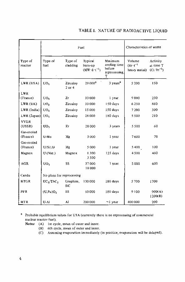
TABLE I. NATURE OF RADIOACTIVE LIQUID
Fuel Characteristics of waste
Type of reactor
Type of fuel
Type of cladding
Typical burn-up (MW-d-t"1)
Minimum cooling time before reprocessing, T
Volume ( l tr -r 1
heavy metal)
Activity at time T (Ci - l tr 1 )
LWR (USA) uo2 Zircaloy 2 or 4
29 000a 3 years3 5 200 150
LWR (France) uo2 Zr 33 000 1 year 9 800 230
LWR (UK) uo2 Zircaloy 33 000 150 days 6 250 860
LWR (India) U 0 2 Zircaloy 15 000 150 days 7 200 300
LWR (Japan) U 0 2 Zircaloy 28 000 180 days 5 500 210
W E R (USSR) uo2 Zr 28 000 3 years 5 500 60
Gas-cooled (France) U-Mo Mg 3 000 1 year 7 600 70
Gas-cooled (France) U/Si/Al Mg 5 000 1 year 5 400 100
Magnox U (Nat.) Magnox 1 300 3 500
125 days 4 500 460
AGR U 0 2 SS 37 000 18 000
1 year 5 000 600
Candu No plans for reprocessing
HTGR UC2/ThC2 Graphite, SiC
100 000 180 days 5 700 1700
PFR (U,Pu)0 2 SS 60 000 180 days 9 100 900(A) 1200(B)
MTR U-Al Al 200 000 year 400 000 200
Probable equilibrium values for USA (currently there is no reprocessing of commercial nuclear reactor fuel). Notes: (A) 1st cycle, mean of outer and inner.
(B) 6th cycle, mean of outer and inner. (C) Assuming evaporation immediately (in practice, evaporation will be delayed).
íS?í
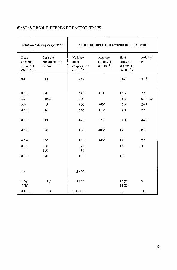
WASTES FROM DIFFERENT REACTOR TYPES
solution entering evaporator Initial characteristics of concentrate to be stored
Heat Possible Volume Activity Heat Acidity content concentration after at time T content N at time T factor evaporation (Ci - l t r 1 ) at time T (W-ltr - 1) ( l t r - r 1 ) (W- l t r 1 )
0.6 14 380 8.3 4 - 7
0.93 20 540 4100 18.5 2.5
3.2 16.5 400 5.3 0 . 5 - 1 . 0
9.0 9 800 3000 0.9 2 - 3
0.59 16 350 3100 9.3 2.5
0.27 13 420 730 3.3 4 - 6
0.24 70 110 4800 17 0.8
0.34 50 100 5400 18 2.5
0.25 50 90 12 3 100 45
0.33 20 100 16
7.5 3 600
4 (A) 2.5 3 600 10(C) 3 5(B) 12(C)
0.8 1.3 300 000 1 - 1
íS?í
3. CONSIDERATIONS FOR THE DESIGN OF WASTE HANDLING FACILITIES
In Section 2 the waste solutions arising from reprocessing different types of fuels were surveyed. In general, they are dilute nitric acid solutions (4— 10m3-1_1). They contain a wide variety of dissolved salts and there is a significant heat release from the fission products (0.2—7 W ltr-1). The prime requirement is to store them safely until further treatment, such as solidification, is adopted. At present, for many countriesthis could imply storage for at least ten to twenty years. When solidification processes come into routine operation, the liquid storage may be reduced to a limited buffer period. The management of these wastes must be integrated with the operation of the reprocessing facility and cannot be on a short-term basis. It must be anticipated, analysed and planned many years in advance.
While safety is the overriding requirement, many factors have to be considered in deciding a storage philosophy. Most high-level waste solutions arising from the reprocessing plant can be concentrated to some extent. The higher the concentration factor, the greater the specific heat release and cooling problems and the greater the chance of precipitation of solids and the resultant handling problems, but the volumes to be stored will be smaller and tank costs may be lower. Each of these factors is analysed in turn.
It is generally agreed that high-level liquid waste will be solidified at some time in the future. It is best to do nothing to the waste that will make solidifica-tion more difficult, such as neutralization with sodium hydroxide.
3.1. SAFETY
Before examining the many technical considerations for the evaporation and tank storage systems, it is important to establish basic safety requirements.
The facilities must be able to handle multi-megacuries daily and they must be designed and operated to the highest standards of integrity and containment. The system must be such that significant quantities of activity cannot escape from the shielded complex either in normal operation or as a result of any conceivable malfunction.
The plant must be reliable and have a negligible leak rate. Any leaks that develop due to corrosion must be detectable and contained by a secondary vessel. Equipment must be available to transfer liquor from a leaking tank rapidly and reliably to a spare storage tank. Airborne effluents from both the evaporator and storage tanks must be treated to prevent the escape of significant quantities of activity, even under conditions of maloperation.
íS?í

All the plants and ancillary equipment must be instrumented to provide adequate process information and to ensure that all effluent streams are con-tinuously monitored. Should excess activity be detected, automatic shut-off or diversion of the stream to a holding tank or bypass system must take place.
At all stages of the operation, the fission-product decay heat must be removed by cooling water or air and all cooling facilities should be duplicated in case of failure of part or all of the normal system. The cooling system must be designed to operate in the presence of solids. The source of cooling water must be guaranteed or an alternative source be available if required in an emergency. Critical equipment and transfer lines should also be duplicated.
No component should be present which will react vigorously (or in an uncontrolled manner) with the nitric acid or nitrates present in the system (such as solvents). Any hydrogen formed by radiolysis must be safely diluted and vented from the system, and any radiolytic chemical changes in the system should be monitored and controlled to maintain the liquor composition within the design limits. This applies particularly to the acidity.
Finally, the bulk liquor storage units and the associated biological shielding must be proof against any anticipated natural events (storm, flood, earthquake) and against the external impact from an aeroplane crash.
3.2. PROCESSING REQUIREMENTS
3.2.1. Evaporation
The fission-product solution coming from the first cycle of the separation plant is usually so dilute that it is not economic to put it directly in the storage tanks. In the Purex cycle, when the only salting agent is nitric acid, it is possible to concentrate the solution from 10-fold to 50-fold and this is normally done in a conventional evaporator. The evaporator must be equipped with both a heat source for evaporation and facilities for cooling to remove decay heat in the event of maloperation. The prime operating problems will be: control of acidity as the solution is being concentrated; control of temperature to minimize corrosion; and the final concentration, particularly if solids are precipitated as the concentration increases. It must be possible at all times for the contents of the evaporator to be transferred to a holding tank, usually one of the high-level liquid waste storage tanks.
The evaporator must be equipped with suitable disentrainment devices: a condenser and off-gas treatment system to ensure that the discharges to atmosphere are at a satisfactory low level. The condensate must be collected in a suitable tank and monitored to ensure that the activity is acceptably low. As an alternative, the condensate can become part of the feed for a low-activity
íS?í
waste concentrator. The overheads can provide part of the feed to the acid fractionator and the bottoms can bè recycled to the high-level evaporators. In cases where the technology of fuel reprocessing does not include the separation of tritium, the evaporation of highly active solutions will result in the predominant part of the tritium being found in the condensate, the handling of which should take this into account. Detailed designs of the different types of evaporator currently in use are described in Section 4.
3.2.2. Storage tanks
The concentration factor achieved in the evaporator is usually limited in order to ensure safe and easy transfer of the liquor to the storage tanks and avoid any risk due to deposition of solids in the transfer system. However, it is becoming common practice to allow further evaporation to occur in the storage tanks, particularly as the fission products decay and the heat load in the tank reduces. The tanks will require a complex arrangement of cooling coils, and in some cases an outer cooling jacket is also provided. The tanks must also be equipped with some form of agitation system to prevent any precipitates from settling, particularly on the base or on cooling surfaces, and there must be provision for transferring the contents to a stand-by tank in the unlikely event of a leak. The bottom of the tank should be kept free of obstructions, such as supports, in order to eliminate places where solids might accumulate. The tank will be surrounded by an outer container which must be large enough to hold the entire contents of the storage tank. This outer container must also be equipped with means of transferring the contents to a stand-by tank. Exxon, USA, is proposing a system in which the high-level liquid waste will be stored in tanks without cooling coils so that the liquid will be self-boiling. Heat removal will be by vaporization and condensation.
Like the evaporator, the tank must have a comprehensive off-gas treatment system. Although the condensation load will be considerably lower, the tanks are normally vented by a flow of air; the agitation is often also done by air pulsation and this air requires treatment in the off-gas system.
3.3. CONCENTRATION FACTOR: CRYSTALLIZATION AND PRECIPITATION
The Purex flowsheet is generally operated to avoid the addition of unnecessary chemicals to the main high-level waste stream apart from the fission products and a significant quantity of iron arising from plant corrosion. This allows the largest practical concentration factor to be achieved before either crystallization (usually iron nitrate) or precipitation (usually due to the presence
íS?í
500
400
£ 300 z o I-< OC
200
O O
100
1 2 3 4 5 6 7 8 9 10 11 12
HNO3 CONCENTRATION (N)
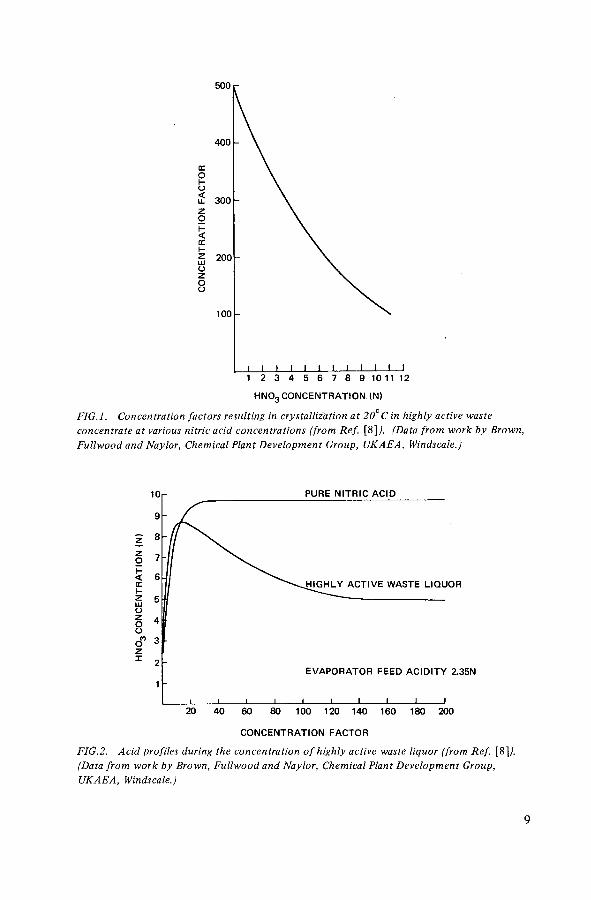
FIG.l. Concentration factors resulting in crystallization at 20°C in highly active waste
concentrate at various nitric acid concentrations (from Ref. [ 8 ] / (Data from work by Brown,
Fullwood and Naylor, Chemical Plant Development Group, UKAEA, Windscale.)
PURE NITRIC ACID
IGHLY ACTIVE WASTE LIQUOR
EVAPORATOR FEED ACID ITY 2.35N
120 140 160 180 200
CONCENTRATION FACTOR
FlG.2. Acid profiles during the concentration of highly active waste liquor (from Ref. [ 8 ]¿
(Data from work by Brown, Fullwood and Naylor, Chemical Plant Development Group,
UKAEA, Windscale.)
9

of phosphoric acid, molybdenum or zirconium) of the concentrate becomes a problem. The crystallization point is affected by the nitric acid concentration, higher concentration factors being possible at lower acidities. The presence of phosphoric acid and fission products has only a minor effect on the crystallization point, but results in the deposition of finely divided precipitates at fairly low concentration factors. In particular, a precipitate with the approximate composition ZrMo2 has been observed to form on the heating and concentration of solutions containing these fission-product elements. The general effect of acidity on the concentration factor which can be achieved before crystallization starts to occur is shown in Fig.l, which is taken from work carried out at Windscale, UK [8],
The acidity in the evaporator depends upon the mode of operation. The system adopted at Windscale is semicontinuous; the waste liquor being continuously fed over some months with a constant level in the evaporator and no take-off of concentrate. During this time the acidity follows the curve shown in Fig.2 [8], rising in the early stages to 8—9N and eventually falling and levelling out to about 5N in nitric acid. The high initial acidity does not result in any increased danger of crystals being formed since, when the acidity is at its highest, the concentration factor and therefore salt concentration is low. The acidity can be reduced below 5N by feeding water at the closing stages when the desired concentration factor has been reached.
The alternative method of reducing acidity is the use of formaldehyde, formic acid or sugar. This practice has not been adopted at Windscale because it was found that the solids that were precipitated were more dense and therefore more difficult to move in the plant; also, formaldehyde does not react smoothly at the temperature of operation (60°C) desired for corrosion reasons.
The method of destroying nitric acid with formaldehyde has been used in France [9] since the beginning of reprocessing and has proved quite safe. It is intended to keep acidity at the lowest practical level in the concentrates in order to minimize corrosion, and the level of 2.5N nitric acid is easily reached. Thus it has not been necessary to use highly corrosion-resistant materials, and stainless steel is used throughout the plant.
The precipitation of solids during concentration is very dependent on local plant conditions. Problems associated with the presence of these solids are the possibility of pipelines being blocked in the plant and the enhanced corrosion that can occur when solids accumulate on equipment surfaces. (This is examined in Section 3.6.) It is usually considered preferable to limit the concentration factor in the evaporator to ensure successful handling and transfer of the liquor to the storage tanks and to obtain a further factor of 2- to 4-fold reduction in volume by slow evaporation in the storage tanks.
Another criterion in determining the maximum concentration factor is to ensure that at all stages the fission-product decay heat can be adequately removed and temperatures controlled.
íS?í
In the case of the very large tanks, it is necessary during the early stages of filling to dilute the waste to cover sufficient cooling coils to control the temperature. As the tank is filled the excess liquid is removed as condensate.
3.4. TANK SIZE
The size of tank for storing high-level liquid wastes depends on the rate of arisings of waste (i.e. reprocessing throughput) and the actual volume to be stored, together with detailed knowledge of the cost of tanks of different sizes, all ancillary services and economic factors such as interest rates, construction times, etc. In assessing the overall economics of various systems it must be remembered that at least one spare tank, and often more, must be available in case of leakage or failure of a tank. The capacity of the spare tank(s) must be adequate to accept the entire contents of any of the tanks in use. Current practice is about one spare for every eight tanks in use. In the section on waste management in the IAEA Study Report on Regional Nuclear Fuel Cycle Centres [10], it was suggested that two spare tanks should be kept available from the first eight tanks constructed. Since tank construction times are at least three years, if only one spare tank is available and it has to be used, three years could elapse before another spare could be made available.
At present, tank sizes in use range from 50 m3 to 1200 m3 capacity. Larger tanks will have a lower cost per unit volume so it would seem desirable to use the largest practical tank size. However, the size chosen must obviously bear some relation to the rate of arising of liquor concentrate, and it is undesirable to commit a large capital sum on a storage scheme based on current technical knowledge, particularly with the prospect of solidification of all high-level wastes by the end of the century. Size can be optimized on the basis of through-put of the facility and economic factors associated with construction and operation. A major factor in such an optimization is the cost of the cooling coils, which is discussed in Section 3.5. A detailed analysis of this problem was presented by Clelland [8], but is not reproduced here as the costs are now out of date.
In the United States of America [11] there are many carbon steel tanks at older reprocessing sites for handling neutralized wastes with capacities of nearly 3800 m3, but since it is now universally agreed that high-level wastes should eventually be solidified, neutralization of wastes is no longer considered desirable at new reprocessing plants.
3.5. COOLING REQUIREMENTS
The provision of cooling in the tanks is subject to variation for the same overall heat load depending upon the following factors:
íS?í

Temperature of the liquor in storage; Average temperature of the external source of cooling water; Overall heat-transfer coefficient; Pipe diameter used for the coils; If more than one storage tank is available, whether the tanks are filled
in series or in parallel.
In addition to coils inside the tank, some tanks are equipped with an outer cooling jacket which can have two other uses: acting as a further line of containment if the main tank leaks and helping to keep the bottom of the tank cool and prevent increased corrosion if solids settle on the tank bottom.
The cooling coils are arranged in a number of parallel circuits, usually with some spare cooling capacity in case of failure of one circuit. They are generally fabricated from piping 5 - 1 0 cm ( 2 - 4 in) in diameter and the complete system is usually very complex.
The Exxon plant proposed for construction near Oak Ridge, USA, will use self-boiling and condensation for cooling, so no coils are used.
In all cases it is important that reliable and redundant sources of cooling water be available. Cooling ponds, cooling towers, wells, rivers and oceans are all potential sources of cooling water, and most sites have a combination of two or more. In the case of a large lake or ocean, one source with multiple transfer lines may be sufficient. At the NFS plant in the United States of America and in France, air-cooled finned heat exchangers provide back-up cooling.
All installations use closed-loop cooling water systems between the tanks and the external cooling-water source. Thus radioactive materials which might be released from a leaking cooling coil would not be transferred to the external cooling water.
3.6. CORROSION CONSIDERATIONS
The study of the corrosion of possible construction materials for the evaporators, storage tanks and all ancillary equipment is of paramount importance in ensuring reliability of the equipment. The main factors in the study of corrosion are temperature, acidity, irradiation of the fuel from which the waste solutions are derived, and the evaporation factor applied to the waste liquors. The material chosen is usually stainless steel, although titanium has been used for evaporators; minor components are sometimes fabricated from other materials, e.g. tantalum mist eliminators in evaporators.
For the storage tanks, which are normally stainless steel, 60—65°C is considered a safe upper temperature limit for corrosion, and this should result in very long life. Current operating temperatures are 50°C or lower. It is not
íS?í

usually practical to keep temperatures of the evaporators as low as 65°C, hence the use of materials such as titanium. An alternative is to operate the evaporator at reduced pressure (e.g. 70 mmHg pressure), when the surface temperature of the heating surfaces will normally be kept as low as 90°C and metal thicknesses must be increased to provide an adequate corrosion allowance for the design life of the equipment. If sulphate and iron are both excluded from the process chemicals used during reprocessing, the corrosion rate for titanium evaporators is very low at the temperatures necessary. For operation at near atmospheric pressures, these units are therefore not usually operated at pressures less than a few centimetres of water vacuum.
Waste tanks should be designed so that corrosion specimens can be installed and removed. Means of carrying out in-service inspection and surveillance of the tank surface by ultrasonics or remote-visual techniques should be available wherever practical. Since the coils are thinner than the outside tank wall, any uniform corrosion should first result in leaks in the coils rather than in the tank walls. If solids are allowed to remain in contact with the tank surface for an extended period, localized heating and corrosion rates much higher than anticipated can occur.
3.7. AGITATION
When the high-level waste solutions are concentrated, both crystallization and precipitation occur, and it is not economic to store the solutions in a dilute form to avoid such effects. Many studies have been carried out to determine the characteristics of the solids and it is now standard practice to provide agitation to maintain these solids in suspension.
In the evaporator, special devices are not required since the boiling liquid is usually sufficient to maintain all solids in suspension. However, three types of agitation system have been widely adopted for use in storage tanks: air spargers, air-lift circulators and ballast tanks (the latter are also referred to as ballast tubes, pulsators and jet sparge units). The object of these systems is to keep particulate matter in suspension and minimize the formation of sludge layers. All these agitators are air-operated and they are mounted inside the tank, supported from the top. The main difference between the systems is that the air spargers and air-lift circulators intimately mix air and solution inside the tank and they provide means for in-tank concentration, while the ballast tanks always maintain an interface between the air and solution inside the ballast tank and hence little evaporation occurs.
Air spargers consist of horizontal pipes positioned near the bottom of the tank with a series of holes that allow air to be dispersed through the tank.
íS?í

FIG.3. Principle of the air-lift circulator (from Ref. [15]J.
The basic principle of an air-lift circulator is shown in Fig.3. A number of such units are usually placed inside the tank and the heights usually vary to allow for the different levels during tank filling.
The ballast tanks are of two types, shown in Fig.4, although the operating mode is similar. In each case, they have a nozzle at the lower end and a compressed-air connection at the top. In operation, the liquor contained in the ballast tank is rapidly expelled through the nozzle by the air pressure, and the jet will sweep the bottom of the tank, removing any solids that have settled. The ballast tank is then allowed to refill with liquid, and the cycle can be repeated. Such units are normally only operated once per hour and sometimes even less frequently. Once the solids have been dispersed by the ballast tanks, the air-lift circulators will maintain this dispersion for some considerable time.
íS?í

( a )
FIG.4. (a) Central ballast tank, (b) Peripheral ballast tank. (From Ref. [\S].)
íS?í

With fast reactor wastes, owing to the higher concentration of «-emitters, it is necessary to keep agitation at a minimum to prevent excessive radiolysis.
3.8. LIQUID TRANSFER
The waste-liquor handling facility must include provision for transfer of the dilute feed from the reprocessing plant to the evaporator, removal of the liquor after concentration, and transfer to any one of a number of storage tanks. The transfer system must allow for the later addition of further tanks within the system. In all these transfers, the precipitated solids must be kept in suspension and temperatures controlled at acceptable levels. All conceivable maloperations must be examined and provision installed to correct the situation safely. All storage tanks must be equipped with means of completely emptying the contents into another tank. Also, the space between the tank and the outer enclosure must be equipped with provision for cleaning and transfer of liquor in case of contamination from a leak. Liquid transfer is usually by steam- or air-operated ejectors or air lifts. Pumps have been used for transfer of liquid wastes in plants equipped to replace the pumps remotely. All critical transfers should have duplicate transfer lines and transfer devices. It is desirable that the duplicate transfer devices should not be of an identical type.
3.9. SAMPLING
As a specific part of the liquid transfer system, provision must be made for sampling at all stages, and this should include both suspended solids and supernatant solutions. All sample lines must be designed to avoid blockage. To obtain representative samples, thorough mixing of the liquor to be sampled is essential and care should be taken in the siting of the sample probes, multiple positions being ideal to enable a number of samples to be obtained from different locations. The construction materials of the sampling system should be carefully chosen to ensure that they do not react chemically with the constituents of the sample.
3.10. LEAK DETECTION
In the event of the failure of a tank or any other piece of equipment holding high-level wastes, it is essential to be able to detect the leak promptly in order to take immediate corrective measures. All heating and cooling coils and services must be continuously monitored. Closed-loop cooling and steam
íS?í

systems are helpful in containing the radionuclides in case of a leak in cooling or heating coils or jackets. The vaults which contain storage tanks or waste-processing equipment should be equipped with sumps and level detection instrumentation to detect leaks. The vault ventilation air should also be monitored for radionuclides in order to detect small leaks that will solidify before they reach a sump where they could be detected by the in-cell instrumentation.
As a final back-up measure, bore holes should be placed round the facility and ground-water samples checked. At Hanford, USA, it has been proposed to install a grid of piping in the ground beneath the tank through which radiation detection instruments can be pulled in order to detect migration from the tank.
3.11. MAINTENANCE
A facility handling megacurie quantities of high-level liquid wastes must be constructed and operated behind heavy shielding (see Section 8). However, an important decision must be taken at the design stage on the philosophy to be adopted for maintenance. There are two basic options:
(a) Design of the plant assuming no remote maintenance. In this case, the equipment must be as simple as possible, usually with key items duplicated and anything that may require attention located in a separately shielded area specially designed for remote (or possibly direct) maintenance. This philosophy is generally adopted in the United Kingdom and France.
(b) Design and installation of the plant with provision for remote main-tenance. In this case, the design includes increased space, viewing windows, remote-handling equipment and special equipment to assist routine main-tenance or replacement of all likely items of plant. This is the normal design philosophy in the United States of America.
íS?í

4. DESIGN AND CONSTRUCTION OF EVAPORATION SYSTEMS
The basic object of the evaporators is to concentrate the waste solutions prior to transfer to the storage tanks. The design philosophy adopted has varied significantly between countries [12]. The choices are:
Batch versus continuous operation; Straight concentration of solutions versus decomposition of excess nitric
acid to bring down acidity and minimize corrosion; Remote maintenance versus no-maintenance and duplication.
In the United States of America, the most recently installed evaporators are operated for continuous direct concentration and are of the external calandria type. They are designed for remote maintenance and replacement and can achieve concentration factors of 10-20 with an acidity 4 - 6 N in the final solution.
In the United Kingdom, the evaporators operate on batches with direct concentration. They can reach concentration factors of 50-100, the final solution having an acidity around 5N. As a no-maintenance philosophy has been adopted, a simple type of jacketed kettle evaporator is used. It is considered that the decontamination of such highly active plant is an expensive and lengthy process and that a general direct maintenance system is impracticable. Instead, it was decided to provide simple equipment of high reliability that should require no maintenance. The highly active section of the plant is duplicated to provide a stand-by unit; this procedure is preferred to the expense and additional complica-tions associated with remote maintenance techniques.
Evaporation is carried out under reduced pressure and this has the advantages of:
(a) Reducing the boiling point of the liquid and therefore limiting corrosion to some degree.
(b) Maintaining a temperature well below what would represent a hazard should tributyl phosphate (TBP) inadvertently be admitted to the system. TBP in an organic solvent is universally used in reprocessing plants as an extradant for uranium and plutonium; when heated in a nitrate system, it reacts exothermically to yield flammable organic vapours. This reaction has been well characterized and does not proceed rapidly at temperatures below 130—135°C.
In France, the primary concern has been to minimize corrosion in those parts of the plant where highly active solutions are being handled. While they
íS?í

are being concentrated, wastes are therefore treated with formaldehyde in order to destroy nitric acid. Under these conditions, evaporation is conducted as a batch process to obtain the maximum concentration depending upon the thermal content of the solutions (i.e. concentration factors of 20—70) while keeping nitric acid concentrations around 2.5N. The jacketed kettle evaporator is used and a no-maintenance philosophy has been adopted, which implies duplication.
It is common practice in reprocessing plants to recycle and re-use nitric acid that has been recovered from the condensate from the evaporators, which avoids having to deal with it as an effluent.
4.1. TYPICAL DESIGNS
4.1.1. Evaporators at Windscale and Dounreay, UK
These are simple jacketed kettle evaporators consisting of a lower evaporation section and an upper column welded together to function as a single unit [8, 13, 14].
In the Dounreay unit, the evaporation section is a vertical cylindrical double dished-end vessel 1.22 m (4 ft) in diameter and 2.13 m (7 ft) high, fabricated from 25.4 mm (1 in) thick 18/13/1 stainless-steel plate. This thickness is reduced to 9.5 mm (0.375 in), 1.83 m (6 ft) from the base. The column, which is 0.46 m (1 ft 6 in) in diameter, 3.2 m (10 ft 6 in) high, and mounted directly on top of the main vessel, has a wall thickness of 9.5 mm (0.375 in).
The evaporation vessel has an outer steam jacket, fabricated from 9.5 mm (0.375 in) 18/8/1 stainless steel, which extends 0.69 m (2 ft 3 in) up the side of the vessel. The annular space is 76 mm (3 in) at the bottom and 48 mm (1.875 in) between the upright walls. The general arrangement is shown in Fig. 5.
The Windscale evaporator is larger, with a liquor capacity of 14 m3 and an equal volume of free space to allow for foaming and for reduction of droplet entrainment. The evaporator section is 3.05 m (10 ft) in diameter and 4.9 m (16 ft) high, with a disentrainment section 2 m (6.5 ft) in diameter and 2.9 m (9.5 ft) high. The bottom is fabricated from 18/13/1 stainless-steel plate 32 mm (1.25 in) thick and the sides 28.6 mm (1.125 in) thick. This evaporator is equipped with an outer jacket and four indépendant coils which can be used for either heating or cooling. The general arrangement is shown in Fig. 6. The operating pressure is 50 -70 mmHg, which is maintained by two-stage steam ejectors connected to the evaporator condenser. Steam at 1.7 kg-cm-2 is used and the boil-up rate by operating the jacket and coils is about 50 m3 • d"1, which is low enough for a simple packed column to be adequate for disentrainment to ensure low carry-over of activity to the distillate. Provision is made for cooling through the same jacket and coils at the end of each batch operation before transfer to storage. A simplified flow diagram of the evaporator and ancillary plant is shown in Fig. 7.
íS?í

FIG.5. General arrangement of eva-porator at Dounreay, UK (sectional elevation). Measure-ments are given in feet and inches, e.g. 8'—2"; see text for main measurements in metric units.
íS?í

FIG. 6. General arrangement of evaporator at Windscale, UK. Measurements are given in feet and inches; see text for main measurements in metric units.

FIRST-STAGE SURGE VESSEL EJECTOR CONDENSER
FIG. 7. Simplified flow diagram of the highly active evaporation plantat Windscale, UK (from Ref. [8]A


NJ
FIG.9. Simplified flowsheet of evaporation plant, La Hague, France.
4.1.2. Evaporators at La Hague and Marcoule, France
Similar designs of evaporators have been installed at both French sites; Fig. 8 presents a general layout of the unit used at La Hague for the concentration of fission-product solutions prior to storage. The unit includes the following equipment:
Feeding unit for buffer storage of the solution coming from the extraction plant; traces of solvent which could have been left in the solutions can be decanted at this stage.
Evaporation unit where the waste solutions are concentrated, with the addition of formaldehyde to destroy nitric acid.
Absorption unit to recombine and absorb nitrous fumes produced in the nitric acid destruction step.
Supply unit for heating and cooling fluids.
The evaporator itself is of the kettle type, made from stainless steel (Z 2 CNS 18-14) 12 mm thick. The bottom part is surrounded by an external jacket where superheated water for heating or cold water for cooling can be circulated. The evaporator has a capacity of about 6 m3. A scrubbing column on top of the kettle separates droplets of solution from the vapour.
Vapour from the evaporator passes through a condenser and the distillates are cooled, while the outgoing gases pass to the absorption unit which consists of a scrubbing column where the gases to be recombined are scrubbed with distillate and some oxygen is injected (see Fig. 9).
The evaporation unit is fed from the intermediate storage tanks through a constant-flow feed distributor which regulates and controls the flow of solution to be concentrated. Operation of the evaporator is checked by measurements of level, density, temperature, pressure, flow and radioactivity. Four sampling points are provided in the evaporator and others are placed on the intermediate storage tanks and the absorption column.
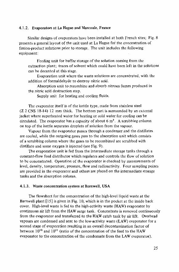
4.1.3. Waste concentration system at Barnwell, USA
The flowsheet for the concentration of the high-level liquid waste at the Barnwell plant [ 15 ] is given in Fig. 10, which is in the pocket at the inside back cover. High-level waste is fed to the high-activity waste (HAW) evaporator by continuous air lift from the HAW surge tank. Concentrate is removed continuously from the evaporator and transferred to the HAW catch tank by air lift. Overhead vapours are condensed and sent to the low-activity waste (LAW) evaporator for a second stage of evaporation resulting in an overall decontamination factor of between 1010 and 1011 (ratio of the concentration of the feed to the HAW evaporator to the concentration of the condensate from the LAW evaporator).
íS?í

FIG.11. High-level liquid waste concentrator (from Ref. [15]) . Measurements in feet and inches.
A portion of the condensed overhead is used as reflux to the single bubble tray in the top of the evaporator. A 2—6 l trh - 1 flow of 0.27M sugar is added to the HAW evaporator feed to suppress ruthenium volatility. The concentrate to the HAW catch tank is blended with water to reduce the acidity of the concentrate from approximately 8N to 4N and to increase the liquid volume. The expanded liquid volume improves heat transfer by increasing the vessel surface contact in relation to the heat generation rate. (Adequate heat transfer is an important parameter in the design and operation of these tanks.) The cooling system removes the fission-product decay heat and reduces the temperature of the contents to below 60°C (to permit jet transfer within the 16-hour catch and sample cycle). HAW concentrate is transferred by ejector from the HAW sample tank to the HAW storage tanks. If sampling indicates that the fissile content is above 1 % of the accountability input, the sample tank contents may be recycled to the sump collection tank for reprocessing.
íS?í

The evaporator vessel is constructed of titanium, with an external titanium thermosyphon reboiler supplied with 1.76 kgf-cm"2 (25 lbf'in"2 (g)) steam (see Fig. 11). No acceleration of corrosion is expected because of the titanium/stainless-steel interfaces. Entrainment is reduced by limiting vapour speed to 0.3 ms" 1
(1 f t s - 1 ) in the reboiler tubes, the reboiler vapour return line and the disengaging head, and by the combined use of a wet bubble tray and a wire mesh pad in the upper section of the evaporator. The vapour speed in the disengaging section of the evaporator is less than 0.127 m • s - 1 (25 ft • min-1 ). The evaporator provides a decontamination factor of between 1 X 10s and 1 X 10⁶. The waste solution is concentrated to 0.568 m3 (150 US gal)/tU (based on a fuel burnup of 35 000 MW • d/tU) from a feed concentration of approximately 5.680 m3
(1500 US gal)/tU. The evaporator vessel is jacketed and cooled by water from the closed-loop cooling system to provide removal of fission-product decay heat. The evaporator reboiler may be operated on either closed-loop cooling water or 1.76 kgf-cm"2 (25 lbf'in"2 (g)) steam. The evaporator and reboiler can be removed and replaced by remote-maintenance equipment. The reboiler tube bundle can be removed and replaced separately. All piping, including instrument lines, is equipped with connectors of the special design developed at Hanford, which allows in-cell cranes to replace the equipment remotely.
Skin thermocouples are used to obtain the temperatures of the recirculating liquid and the vapour above it. Bubble-type instrument probes are installed to determine the liquid level and the density of the liquid in the evaporator. The pressure instruments also activate alarms and shut down the evaporator by turning off the steam and starting the cooling water if normal operating parameters are exceeded. In addition to the bubble caps and wire mesh, the vessel has an internal steam ejector for recirculating the liquid within the vessel during cleanout or decontaminating operations.
A spray ring is provided above the bubble cap to allow water or chemicals to be added to the vessel to improve the decontamination factor of the condensate during operation or to enhance decontamination of equipment.
4.1.4. Evaporators at Eurochemic, Mol, Belgium
Two evaporators have been used at Eurochemic for concentration of fission-product solutions. They both consist of three sections (joined by truncated cones (see Fig. 12)):
A cylindrical boiler 2.1 m in diameter and 1.65 m high; A cylindrical chamber for foam breaking and vapour separation 2.5 m in
diameter and 1.55 m high; A scrubber column 1.2 m in diameter and 3.16 m high.
íS?í
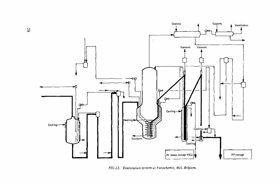
FIG.12. Evaporation system at Eurochemic, Mol, Belgium.
The boiler of one evaporator is equipped with five coils for heating or cooling, while the heating for the other evaporator is provided by four jackets round the boiler. For both boilers, the steam temperature is kept below 135°C and the pressure inside each boiler is 0.4 atm. Steam can be injected into the bottom of the evaporators through a pipe, which can also be used for compressed air to agitate the solutions.
The evaporators are fed at constant flow by means of two-stage air lifts. Concentration is batchwise, the length of cycle depending upon the type of fuel treated. The concentrates are cooled in the evaporators by means of cold water before withdrawal and transfer to the storage tanks.
The scrubber columns contain eight bubble cap plates. Vapour is scrubbed by refluxing distillate or by liquid fed from outside.
4.1.5. Evaporator at Tokai, Japan
The flow diagram of the highly active liquid waste (HALW) concentration unit at the Tokai plant is given in Fig. 13. HALW in the Tokai plant [16] comprises the aqueous effluent (raffinate) from the co-decontamination process, the effluent from the solvent regeneration process and the concentrates from the acid recovery system.
HALW is fed to the evaporator where both concentration and nitric acid decomposition by reaction with formaldehyde take place simultaneously. Concentrated and de-acidified HALW is transferred to the storage tanks at the rate of about 0.35 m 3 -d _ 1 with a specific activity of 107 Crm~3. The stored HALW will be reconcentrated after an interval of two years' cooling.
Most of the solutions are fed by submerged air lifts, ensuring a constant feed flow-rate. The formaldehyde is also fed at a constant rate.
The vapour from the evaporator flows into a horizontal condenser. The non-condensable gases (mainly nitrous fumes and carbon dioxide) flow to an absorber in which the nitrous fumes are oxidized into nitric acid by the air and scrubbed with distillate. The recovered nitric acid flows into a buffer tank and is pumped to the acid recovery unit. Operation of the evaporator is checked by the measure-ment of level, density, temperature, pressure, acidity, concentration of the salts, flow and radioactivity. The temperature is kept below 135°C by restricting the temperature of the heating steam. If the pressure in the evaporator increases to a certain level, it activates a protection device which shuts down the evaporator by stopping the feed and the heating steam and by starting the cooling water.
The evaporator consists of a vertical cylindrical shell with a flat bottom slightly inclined to permit emptying as thoroughly as possible. It is heated externally through the shell, through the bottom by welded half-pipes, and internally by three coils. The heating fluid is steam at 135°C. The evaporator has a capacity of about 3 m3 and is made of stainless steel (Uranus 65)
íS?í

lb> o
CONCENTRATE
STORAGE VESSELS
FIG.13. Flow diagram of HALW treatment system at Tokai, Japan (from Ref. [16];.

12 mm thick. A decontamination column is welded on the top of the evaporator. It is fitted with five bubble cap trays. Furthermore, a cyclone is installed in the lower part of the column.
4.1.6. Evaporators in India
The evaporators used are of the natural circulation type. The general arrangement of the evaporator, indicating relevant details, is shown in Fig. 14. The evaporator consists of a reboiler section, a tank for vapour liquid disengagement and a disentrainment tower.
The construction material of all sections of the evaporator is stainless-steel ASTM type 304L. The reboiler is provided with tube bundles as well as a jacket which can be used for heating or cooling. The heat-transfer area provided is 6.36 m2 in the tube bundle and 0.76 m2 in the jacket. The reboiler section is 1.4 m high. The tank is 1.2 m in diameter and 1.35 m high, and is constructed of 10-mm-thick plates. The disentrainment tower is 0.3 m in diameter, 0.75 m high and provides for a three-stage disentrainment.
Steam at 3.0 kgf-cm""2 pressure is used and the maximum boil-up rate is about 0.6 m3 "h"1. The feed liquor is fed into the bottom of the reboiler and joins the concentrate recycled from the downcomer. Part of the concentrates is continuously removed from the bottom, cooled and routed to an interim storage tank. The overhead vapours from the tank are condensed and partially recycled to the evaporator to control acidity.
Other relevant details are shown in Fig. 14. The decontamination factor of the equipment (ratio of activity of the feed to the activity of the condensate) is about 1 0 4 - 1 0 s .
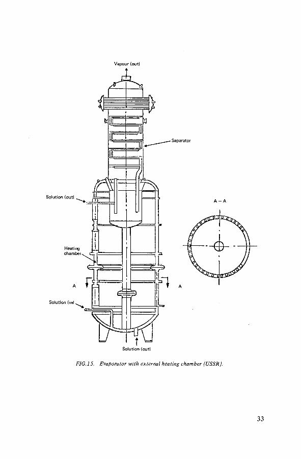
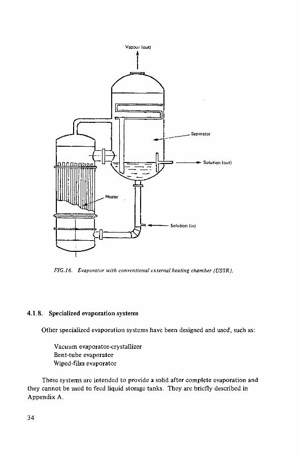
4.1.7. Evaporators in the USSR
For concentrating high-level waste solution, two types of evaporators are used[17]. The first has an external annular heating chamber (see Fig. 15) in which the tubes to the heating chamber are welded to the outside of the evaporator, thus making it unnecessary to dismantle the whole device for maintenance of the heating chamber. The evaporator can process up to 50 m3 in 24 hours. The second type of evaporator has an external thermosyphon reboiler and can process over 50 m3 in 24 hours (see Fig. 16). In both cases a thirteen-fold concentration is obtained and the nitric acid is recycled.
íS?í

OJ to
Feed line
Tube bundle
Jacket
Reboiler shell
Remotely operable nuts Disentrainment
tower
Decontamination spray nozzle
Steam jet
EQUIPMENT Fluid handled:
Volume:
Capacity:
Tank — highly radioactive liquid waste solution of nitrates of various radioisotopes in nitric acid (4 M) Jacket and tube — steam Tower — radioactive off-gas Maximum operating — 600 Itr Normal operating — 150 Itr Tube bundle - 400 Itr-h -1
Jacket - 60 ltr-h"1
DESIGN DATA
Construction: Fusion welded, inert-gas shielded arc welding of radiographic quality
Code: ASM E Section V I I I , Div. 1
Construction material: SS type 304L
Operating
Temperature Pressure
Tank and tower Tube bundle 100 C 0.7 kgf-cm 2 (a)
DESIGN Temperature Pressure Heat transfer area Disentrainment factor
150 C Full vacuum
150 C 3.5 kgf-cm"2 (g)
175 C 5.5 kgf-cm"2 (g) 6.36 m 2
K ^ - I O 5
Jacket
125°C 1.0 kgf-cm"2 (g)
150 C 2.0 kgf -cm 2 (g) 0.76 m 2
AUXIL IARY EQUIPMENT
Jet pumps: 'Capacity — 25 Itr-min"1
Motivating fluid — steam at 5—6 kgf-cm"2 (g) Construction — all welded
Air sparger: Capacity — 100 standard Itr-min"1
Decontamination spray nozzle: Capacity — 25 Itr-m"1
FIG.14. Thermosyphon evaporator (India).
Vapour (out)
FIG.15. Evaporator with external heating chamber (USSR).
33
Vapour (out)
FIG.16. Evaporator with conventional external heating chamber (USSR).
4.1.8. Specialized evaporation systems
Other specialized evaporation systems have been designed and used, such as:
Vacuum evaporator-crystallizer Bent-tube evaporator Wiped-film evaporator
These systems are intended to provide a solid after complete evaporation and they cannot be used to feed liquid storage tanks. They are briefly described in Appendix A.
3 4

4.2. CONSTRUCTION (see also Section 5.3)
The evaporators are made from stainless steel or titanium and every care is taken during construction to prevent leaks and inhibit corrosion. Therefore, in kettle evaporators there are no connections to the bottom of the evaporators or below the liquid level and, as far as possible, supports along the walls are avoided. However, thermosyphon evaporators have feed lines in the bottom but these evaporators are often replaceable by remote methods.
The number of welds is limited by the use of steel sheets of the maximum size compatible with the design. Construction in a workshop with subsequent transport and installation on site is the preferred method wherever possible. The most widely used fabrication technique is butt welding using specially developed specifications for manufacture and testing as described in Section 5.3 and Appendices B and C.
4.3. INSPECTION AND TESTING
Comprehensive and stringent inspection and testing procedures are applied to all stages of supply and manufacture and are generally as described in Section 5.4 for the storage tanks.
íS?í

5. DESIGN AND CONSTRUCTION OF STORAGE TANKS AND ASSOCIATED EQUIPMENT
The basic requirements for a storage tank system have been outlined in Section 3. Tanks currently in use or projected for the future range in size from 50 m3 up to 1200 m3 , generally depending on the reprocessing plant throughput, which in turn depends on the nuclear power generation and the types of reactor employed. In some cases the tank size is dictated by the necessity to limit the tank height to suit the liquor transfer ejector systems. Spare capacity (empty tanks) is always provided to receive the contents of a full tank in case of emergency (see Section 3.4).
The general design of storage tanks is similar for all countries storing highly active liquid wastes. As reprocessing throughputs have increased, tank sizes have increased and improvements have been introduced which include cooling jackets on the main tank body, increased cooling-water circuits with duplication, and more sophisticated instrumentation. The basic design principles common to all tanks are highlighted below, and examples of typical installations are described.
5.1. DESIGN
5.1.1. Tanks
The tanks are usually manufactured from stainless steel with a low carbon content (such as type 304L or 18/13/1). The tanks that cool acidic wastes by condensation of the vapour from self-boiling liquid wastes are constructed of titanium. Tanks are of cylindrical construction and they can be positioned with the axis horizontal or vertical, the latter being more common in the later designs and larger sizes. All internal services, such as cooling coils, agitation devices and instruments, enter from the top of the tank and are suspended so that nothing touches the bottom of the tank. This is to minimize the chance of suspended solids settling on the bottom in crevices, which could lead to increased localized corrosion.
The tanks are located, either singly or in groups, in heavily shielded cells and are placed on suitable supports to allow access to the underside base of the tank.
5.1.2. Cells
All high-level waste storage tanks must be located in thick-walled concrete cells which are normally excavated at least partially, if not wholly, below ground
36

level. This provides on all sides protection to personnel from radiation as well as safety from external mishaps, such as aircraft crashes (see Section 9). The floor and walls of the cell will be lined with stainless steel to a height sufficient to contain the entire contents of a tank in the unlikely event of a leak. A gradual slope in the cell floor will lead to a sump, and cell wash-down pipework will also be included for decontamination. The design of the tank support structure and the enclosing cell should take into account the possible increase in the ground-water level. The entire system may be buoyant when the tank is empty and the ground-water level high. Special drainage and construction may therefore be required, and details vary with site and facility design.
5.1.3. Cooling system
This comprises a series of separate internal cooling coils with sufficient heat removal capacity to cope with the maximum thermal output envisaged for the tank liquor contents. Spare cooling coils will be provided. The cooling-water supply system is duplicated and incorporates a stand-by source of electrical power for the circulating pumps.
5.1.4. Instrumentation
Level indication is included in the tank and cell sump. The temperature of the tank contents is monitored at different levels in the tank and round the base; access is provided through the top of the tank for introducing corrosion specimens. Gas sparging or pulsing of the tank's contents is a common feature, and lines are included to purge hydrogen from the space above the liquor in the tank.
Replication of 'alarm' instrumentation is generally practised and includes, among others:
(a) High- and low-level alarms for the tank's contents; (b) Indication of activity in the cooling-water stream leaving the tank; (c) Sump probe alarms; (d) Monitoring of the ventilation extract system gas flow; (e) High temperature.
Automatic operation to stop the cooling-water supply is normally included in the event of the alarms operating in (a) and (b) above.
5.1.5. Transfers
Transfer of the contents of one tank to another or to a future extension of the facility, and emptying the cell sump, is carried out by ejectors, vacuum lifts,
37
U ) oo
COOLING COILS
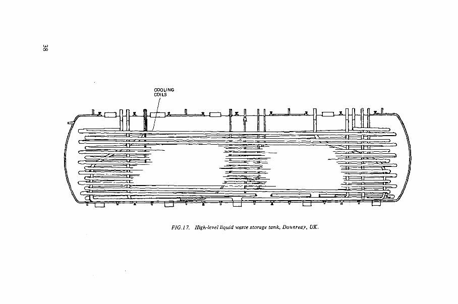
FIG J 7. High-level liquid waste storage tank, Dounreay, UK.
air lifts, vacuum-assisted air lifts or fluidic pumps. The transfer operations are duplicated, preferably by a combination of any two of the methods mentioned.
5.1.6. Ventilation
The extract system from the storage facility is directed to a ventilation stack. It is usual for the gas stream to include high-efficiency filters, disentrainment columns and/or electrostatic precipitators (see Section 6.2).
5.2. TYPICAL DESIGNS
5.2.1. Early storage tanks at Windscale and Dounreay, UK
The wastes from the first separation plant at Windscale were stored in eight tanks of 70 m3 capacity. These were of the horizontal cylindrical type, 3.05 m (10 ft) in diameter and 9.14 m (30 ft) long, and fitted with 100 mm (4 in) dia-meter cooling coils. Four of the tanks had cooling capacity for 0.176 MW and four for 0.41 MW each. These tanks were not fitted with water jackets or agita-tion facilities. The waste solution stored in them was from low-burnup Magnox fuel and little precipitation or crystallization occurred at the concentration factor of 150 chosen for the tanks.
A similar design of horizontal cylindrical tank has been used at Dounreay (see Fig. 17) for the wastes from fuel reprocessing from the Dounreay Fast Reactor (DFR) and from the Materials Testing Reactor (MTR). Twelve tanks are in use, the last four being increased to 80 m3 capacity by extending the length to 12.2 m (40 ft). The general layout of the cell for these four new tanks is illustrated in Fig. 18. The cooling coils are constructed from 76 mm (3 in) diameter pipe and there are five horizontal circuits.
5.2.2. Present storage tanks at Windscale, UK
A new tank design was adopted in the early 1960s [8,13,14] of larger size and with increased cooling capacity and means of agitation. It has a capacity of 150 m3 and is an upright cylinder, 6.1 m (20 ft) in diameter and 6.1 m (20 ft) high, with flat bottom and top. It is fabricated from 18/13/1 stainless-steel plate and has a multipass cooling-water jacket of 18/8/1 stainless steel which covers the bottom of the tank and the lower 0.9 m (3 ft) section of the sides. In later designs this jacket has been extended to the full height of the tank. The general arrangement is shown in Fig. 19.
39

o
1 STORAGE TANK 80 m3 U Oft ( 2 BATCH TRANSFER VESSEL U 0«) 3 INLET D1VERT0R t BREAK POT CELL 5 BREAK POT (2 oft) 6 RECYCLE /DISCHARGE DIVERTÛR ? SAMPLE GLOVEBOX B SAMPLE BULGE 9 C.W. MONITORS
10 RESTRICTED ACCESS CORRIDOR 11 HIGH-ACTIVE DUCT 12 EXISTING PLANT
FIG. 1$. High-level liquid waste storage cell extension, Dounreay, UK.

FIG. 19. Sectional elevation of high-level liquid waste storage tank, Windscale, UK; general arrangement for Tanks 9, 10 and 11.
Modification for later tanks: Tank 12: jacket height increased to 18 ft. Tanks 13-1 7: Modified base supports structure. Tank 18 onwards: Reverse flow diode emptying system being evaluated.
The cooling-water coils consist of 1219 m (4000 ft) of 100 mm (4 in) nominal bore 18/13/1 stainless-steel pipe in the form of hairpin pancake coils. The coils are arranged in seven independent circuits in parallel and the total cooling capacity from both the coils and jacket is 2 MW. The complete coil assembly, together with four air-lift circulators, is hung from a portal framework which is mounted externally to the tank and stands on the tank base slab.
The tank is also equipped with seven jet-sparge units; six are mounted on the inside wall of the tank, equispaced around the periphery, and the seventh is in the centre. These units ensure dispersal of all solids in the tank and, together with the air-lift circulators, ensure complete homogeneity.
41

t o Cooling water out let
FIG.20. Simplified flow diagram of new storage tank and associated equipment, Windscale, UK (from Ref. [13]A
The walls of the concrete cell in which the tank is located are lined with 18/8/1 stainless-steel sheet up to a level which would contain the complete contents of the tank. The tanks are fitted with thermocouples, four force-lift ejectors for liquor transfer to other tanks, and pneumatic depth-measuring (which also measures liquor density). The space between tank and liner is also equipped with ejectors, to transfer any liquor to another tank, and with monitoring devices to give immediate warning if any activity escapes from the tank. A simplified flow diagram of the new storage tank and associated equipment is shown in Fig. 20.
5.2.3. Storage tanks at Marcoule and La Hague, France
The storage tanks installed at the two reprocessing sites in France [9] have capacities from 50 m3 to 120 m3 . They are all vertical cylindrical tanks, the later tanks having ¿orne improvements on the early ones installed at Marcoule nearly twenty years ago.
A typical storage facility built at La Hague has four stainless-steel tanks, each with a capacity of 120 m3 ; they are arranged in two heavy concrete cells, each having two tanks. Another current arrangement is to have four tanks in the same cell with two receiving pans, each capable of receiving the contents of one tank. Solutions to be stored are first received in a 10 m3 delay tank from which they can be sent through an ejector to a rotating feed distributor to flow by gravity to the selected storage tank. (See Fig.21 for the general layout of a tank and ancillaries.)
Ancillary equipment in the storage facility provides for:
Cooling-water circulation in coils inside each tank, to keep the temperature down to 60°C; Agitation of the tank's contents to prevent deposition of suspended solids; Sweeping air above the liquid surface inside the tank to eliminate radiolytic hydrogen; Cleaning off-gases.
The tanks are 6.8 m in diameter and 4.8 m high. They are made from stainless-steel Z 2CND 17-12, with walls 10 mm thick. Each tank sits on a ring in the concrete cell over a receiving pan covering the bottom of the cell and the walls up to a height sufficient to collect the full contents of the tank if necessary. Cooling is provided at the lowest point to keep the temperature of the liquid below 60°C, so as to be able to use an ejector for emptying.
The cooling capacity of each tank is 2.32 MW (2 X 10⁶ kcal • h"1). Cooling is provided by cold water circulating inside ten coils arranged in two independent groups of five, with the possibility of isolating any one in case of a leak.
43

Shielded Fans filters Heater AIR AGITATION COOLING COOLING WATER
General services
Concentrate from vitrification plant
Vitr i f ication plant
C « = ^ ? a en r e
Sunken lining
FIG.21. Fission-product storage tank, La Hague, France.

PROCESS PIPING
FIG.22. High-level liquid waste storage tank, Barnwell, USA.
Agitation in each tank is provided by a central air puiser that forces liquid along the bottom of the tank. The air from the pulser also carries away radio-lytic hydrogen, extra air being added for sweeping out gases. Off-gases are cleaned by being passed through a scrubbing column and a high-efficiency filter. The transfer of solution from one storage tank to the next or to a relay tank is made with vapour ejectors, of which there are four in each tank. Samples can be withdrawn at four different heights in each tank by using an air lift which circulates the solution in a sampling loop (see Section 6.4). Control instrumentation on each tank includes:
Density measurement at different levels by air bubbling; Level measurement by air bubbling; Pressure measurement; Temperature measurement at four places inside the tank and four places
along the bottom.
5.2.4. Storage tanks at Barnwell, USA
The waste storage tank [15] is a vertical right cylinder 16.46 m (54 ft) in diameter and 6.10 m (20 ft) high, constructed from type 304L stainless steel (see F ig.22). The net capacity of the tank is 1135 m3 (300 000 US gal) with 10%
45

C = C E N T R A L B A L L A S T T A N K S ITW = INSIDE OF T A N K W A L L
P = P E R I P H E R A L B A L L A S T T A N K S OH = 6X6- in O U T L E T H E A D E R S
FIG.23. Arrangement of cooling coils, air-lift circulators and ballast tanks in a Barnwell, USA, storage tank (from Ref. [IS]).
4 6

freeboard. The tank is equipped with 48 horizontal cooling coils, 18 peripheral ballast steam ejectors for removing liquid from the tank (part are submerged when the tank is partially filled) a pressure/vacuum relief system, multiple external skin thermocouples, and ten instrument dip tubes (see Fig.23). Some of the thermocouples are installed on the tank exterior sidewalls, spaced to monitor vertical temperature gradients in the tank contents. Most of the thermo-couples are on the exterior of the tank bottom to detect the build-up of heat-generating solids, if it should occur. The dip tubes for the measurement of liquid levels vary in length to cover the expected ranges in liquid level with an acceptable accuracy. The tank internals are supported from the top to allow free circula-tion of fluid from the ballast tanks. Except for the dip tubes, there is no equip-ment less than 76.2 mm (3 in) from the tank bottom. Thus, build-up of solids is minimized. The tank is supported off the vault floor by strips of stainless steel 12.7 mm (0.5 in) thick and 25.4 mm (1 in) wide to facilitate drainage in the unlikely event of a leak. 25.4 mm ( 1 in) diameter drainage holes are provided in the horizontal reinforcing bands on the outside wall of the tank.
The thickness of the tank base and walls up to 2.44 m (8 ft) is 12.7 mm (0.5 in) but is reduced to 11.1 mm (0.437 in) above 2.44 m (8 ft). The corrosion allowance for the tank is 3.175 mm (125 mil), except for surfaces wetted on both sides, which have a 6.35 mm (250 mil) corrosion allowance. The expected corrosion rate is less than 0.008 mm (0.3 mil)/a. The tank is designed for a liquor density of 1.35 and is equipped with a pressure vacuum relief system to ensure that the range of operating pressure does not exceed a pressure of 76 mm (3 in) water or a vacuum of 254 mm ( 10 in) water. Outside this range, a water seal is disturbed and permits communication with the vault.
The cooling system is designed to remove 10.84 MW of decay heat. The cooling coils are divided into six separate parallel banks. They are constructed from 50.8 mm (2 in) diameter schedule-80 stainless-steel pipe and have a total length of 10 826 m (35 520 ft). Coils from different banks are alternated vertically throughout the tank so that each bank can cover the whole height of the tank. Any bank can be isolated from the others if a leak should develop. The coils are part of a closed cooling-water loop which includes multiple plate and frame heat exchangers and multiple centrifugal pumps. Two spare exchangers and pumps are installed to ensure a spare, even if one unit is down for maintenance. There are three sources of cooling water. Normal operation is through a closed-loop cooling tower. Wells provide a back-up, with one normal and two spares installed to ensure availability of well water. This equipment can operate on electrical power from the utility or from either of the emergency diesel-driven electrical generators. If all of these should fail, there are two diesel-driven centrifugal pumps which can circulate cooling water from a conditioning pond directly into the tank cooling coils.
47
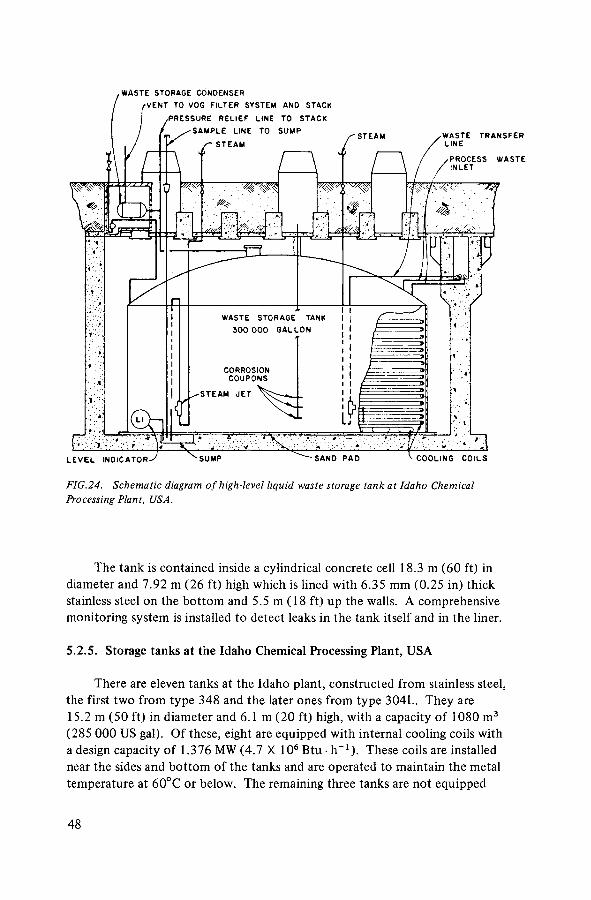
WASTE STORAGE CONDENSER
FIG.24. Schematic diagram of high-level liquid waste storage tank at Idaho Chemical Processing Plant, USA.
The tank is contained inside a cylindrical concrete cell 18.3 m (60 ft) in diameter and 7.92 m (26 ft) high which is lined with 6.35 mm (0.25 in) thick stainless steel on the bottom and 5.5 m (18 ft) up the walls. A comprehensive monitoring system is installed to detect leaks in the tank itself and in the liner.
5.2.5. Storage tanks at the Idaho Chemical Processing Plant, USA
There are eleven tanks at the Idaho plant, constructed from stainless steel, the first two from type 348 and the later ones from type 304L. They are 15.2 m (50 ft) in diameter and 6.1 m (20 ft) high, with a capacity of 1080 m3
(285 000 US gal). Of these, eight are equipped with internal cooling coils with a design capacity of 1.376 MW (4.7 X 10⁶ Btu • h - 1 ) . These coils are installed near the sides and bottom of the tanks and are operated to maintain the metal temperature at 60°C or below. The remaining three tanks are not equipped
48

with cooling coils and are used for low-activity wastes. The tanks are installed underground in unlined concrete vaults. Off-gases from the tanks pass through condensers and filters before they discharge to the atmosphere through a stack. A general layout of one of the tanks is shown in Fig.24. The waste solutions arising from the wide variety of fuels reprocessed in the Idaho plant are now converted to a calcine in the waste calcining facility [18]. The tanks can be considered as buffer rather than long-term storage tanks, although the same degree of integrity is required.
5.2.6. Storage tanks at the Exxon Plant, USA
The proposed Exxon reprocessing plant near Oak Ridge, Tennessee, pro-vides only for short-term storage of high-level liquid wastes. The Preliminary Safety Analysis Report indicates that there will be three vertical right cylinder tanks 4.6 m (15 ft) in diameter and 2.1 m (7 ft) high, each with a nominal capacity of 37.9 m3 (10000 US gal) (Fig.25). The tanks are to be constructed of titanium and will be installed in a remotely maintained processing cell.
The waste solutions are permitted to self-boil to remove the heat of radio-active decay. Vapours are routed to a primary condenser; the condensate is routinely returned to the tank of origin, although an alternative routing to a condensate catch tank would permit self-concentration if desired. The condenser is designed to remove 2.93 MW (107 Btu • h_ 1 ). A redundant condenser will ensure that cooling can be maintained at all times. Sugar can be added to any tank to suppress ruthenium volatilization if needed.
Solution is transferred from the tanks either by pump (equipped with cooled inlet) or water jet.
5.2.7. Storage tanks at Eurochemic, Mol, Belgium
Because the characteristics of the two types of waste arising from the Eurochemic reprocessing plant are very different, two different designs of tank have been installed. The waste solution from LWR fuel reprocessing is stored in two 40-m3 double-wall tanks. The primary storage tank is supported in the middle, inside a secondary containment tank. The overall dimensions are: storage tank, 10.7 m long and 2.4 m in diameter; containment tank, 10.83 m long and 2.6 m in diameter. The axis of the tanks is horizontal (see Fig.26). A head room of 40 cm is left above the maximum liquid level when the tank is considered full.
The tanks are constructed from type 304L stainless steel. The inner tank has a wall thickness of 13 mm, which includes a 3 mm corrosion allowance. A corresponding allowance is also.provided for the cooling coils. Because of the different expansions of the two tanks, all pipes are introduced in the middle
49

N O Z Z L E S C H E D U L E :
1. Air sparger
2. Liquid inlet
3. REA intet
4. REW inlet
5. Condensate inlet
6. Vapour outlet
7. Agitator flange
8. Overflow outlet
9. Jet outlet
10. Pump outlet
11. Jet water outlet
12. Chemical addition inlet
13. Cooling-water inlet
14. Cooling-water outlet
15. Weight factor density and pressure instruments 16.
Temperature instruments
17. Corrosion probe
18. Corrosion test coupons
E L E V A T I O N
FIG.25. High-level liquid waste storage tank at Exxon plant, USA.
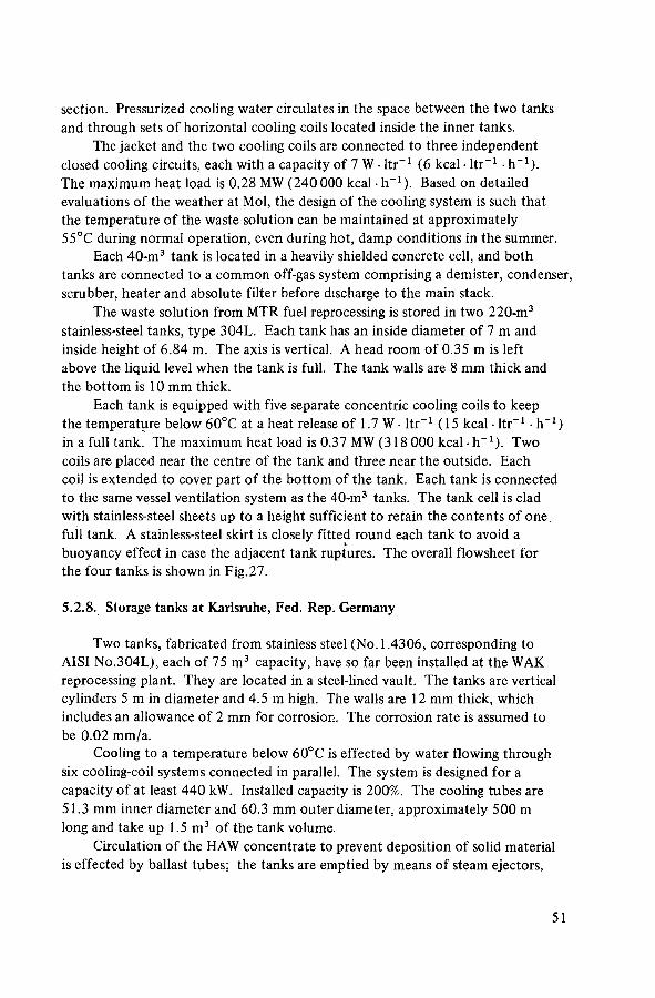
section. Pressurized cooling water circulates in the space between the two tanks and through sets of horizontal cooling coils located inside the inner tanks.
The jacket and the two cooling coils are connected to three independent closed cooling circuits, each with a capacity of 7 W • ltr"1 (6 kcal • ltr"1 • h"1). The maximum heat load is 0.28 MW (240 000 kcal h"1). Based on detailed evaluations of the weather at Mol, the design of the cooling system is such that the temperature of the waste solution can be maintained at approximately 55°C during normal operation, even during hot, damp conditions in the summer.
Each 40-m3 tank is located in a heavily shielded concrete cell, and both tanks are connected to a common off-gas system comprising a demister, condenser, scrubber, heater and absolute filter before discharge to the main stack.
The waste solution from MTR fuel reprocessing is stored in two 220-m3
stainless-steel tanks, type 304L. Each tank has an inside diameter of 7 m and inside height of 6.84 m. The axis is vertical. A head room of 0.35 m is left above the liquid level when the tank is full. The tank walls are 8 mm thick and the bottom is 10 mm thick.
Each tank is equipped with five separate concentric cooling coils to keep the temperature below 60°C at a heat release of 1.7 W • ltr"1 (15 kcal • ltr"1 • h"1) in a full tank. The maximum heat load is 0.37 MW (318 000 kcal - h"1). Two coils are placed near the centre of the tank and three near the outside. Each coil is extended to cover part of the bottom of the tank. Each tank is connected to the same vessel ventilation system as the 40-m3 tanks. The tank cell is clad with stainless-steel sheets up to a height sufficient to retain the contents of one full tank. A stainless-steel skirt is closely fitted round each tank to avoid a buoyancy effect in case the adjacent tank ruptures. The overall flowsheet for the four tanks is shown in Fig.27.
5.2.8. Storage tanks at Karlsruhe, Fed. Rep. Germany
Two tanks, fabricated from stainless steel (No. 1.4306, corresponding to AISI No.304L), each of 75 m3 capacity, have so far been installed at the WAK reprocessing plant. They are located in a steel-lined vault. The tanks are vertical cylinders 5 m in diameter and 4.5 m high. The walls are 12 mm thick, which includes an allowance of 2 mm for corrosion. The corrosion rate is assumed to be 0.02 mm/a.
Cooling to a temperature below 60°C is effected by water flowing through six cooling-coil systems connected in parallel. The system is designed for a capacity of at least 440 kW. Installed capacity is 200%. The cooling tubes are 51.3 mm inner diameter and 60.3 mm outer diameter, approximately 500 m long and take up 1.5 m3 of the tank volume.
Circulation of the HAW concentrate to prevent deposition of solid material is effected by ballast tubes; the tanks are emptied by means of steam ejectors,
51

FIG.26. High-level liquid waste storage tank (LEU) at Eurochemic, Mol, Belgium (in mm).

and samples are taken with air lifts. A forced air circulation system helps to prevent the accumulation of radiolytically generated hydrogen. Exhaust air is fed to the stack through condensers and filters. For monitoring purposes a check is kept on the composition and temperature of the HAW concentrate, the liquid level in the tank and in the catch tray, and on the temperature and quantity of the primary and secondary circuit cooling water.
5.2.9. Storage tanks at Tokai, Japan
The HALW storage facility [16] consists of four storage tanks, three for normal use and one spare, together with other ancillary equipment. The storage capacity will be sufficient for five years.
Each tank is 6 m in diameter and 4.5 m high, with a capacity of 90 m3 , and is fabricated from stainless steel (SUS 316L; C < 0.02). The tanks are installed in two cells. The tanks are equipped with a number of cooling coils, fed from a closed-loop cooling system, to keep the contents below 65°C. A central air pulsator of 0.9 m3 volume is installed to prevent solids from settling on the bottom of the tank. The general arrangement is shown in Fig.28.
The solution to be stored is diverted by one of two rotatable distributors, the other being a spare. After about two years, when a storage tank is full, the solution is recycled to an evaporator to reduce the volume from about 0.35 m3 • d"1 to 0.18 m3 • d _ 1 . It is first transferred to a 1-m3 buffer vessel by steam jet, which is also used to transfer the contents into a spare tank if a tank is damaged. Transfer from the buffer vessel is by an air lift.
The off-gas from the tanks consists of air used for agitation and air used to dilute the hydrogen, which is fed into the tank via a circular perforated pipe fitted in the upper region of the tank. The off-gas passes through condensers, a scrubbing column, a cooler-heater and then a high-efficiency filter. The instrumentation in each tank consists of:
Density measurement at four different levels; Liquid level measurement using two different dip-tube devices; Pressure measurement, with an alarm for over-pressure; Temperature measurement at different levels and on the tank bottom to
check that there is no precipitation (an alarm is activated above 65°C).
5.2.10. Storage tanks in the USSR
High-level liquid waste is transferred after evaporation to a storage facility comprising a group of stainless-steel tanks with a total capacity of 7500 m3 , individual tanks ranging in size up to 1200 m3 [19, 20], The tanks are in the form of vertical cylinders, located in concrete canyons with an external tank
53
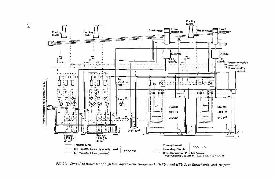
From extension
extens. interconnection manifolds 2-year cooling
circuit
40 m ' 40 m' Transfer Lines
Int. Transfer Lines (by gravity f low)
Int. Transfer Lines (pressure)
COOLING Primary Circuit
Secondary Circuit Cross Connection Possible Between 1-year Cooling Circuits of Tanks HEU 1 & HEU 2
FIG.27. Simplified flowsheet of high-level liquid waste storage tanks (HEU 1 and HEU 2) at Eurochemic, Mol, Belgium.

¡Steam (in)
^D i s t r i bu to r v X
/ •-• ' ; • i"-.. ."•>'.
y - A i r purge (in) ^ H A L W concentrate (in)
t To spare Pulse air
y -S team (in) / HALW concentrate
i * — r p o u t , i
» r » Cooling water (nutl
_ r
, Valve
/ f N Level '—' warning indicator •
1 * . . ' " _ - • f ' 6000 mm 0 X 4500 mm high
• \ - . Capacity 90 m 3
\ V
FIG.28. Sketch of high-level liquid waste storage tank at Tokai, Japan (from Ref. [16]).
(or liner) in case of leakage. The tanks are linked by a pipe system to enable solution to be transferred from one tank to another. The general layout is shown in Fig.29. A tank-life of 2 5 - 3 0 years is assumed, and new tanks are constructed to transfer the liquor from old tanks as well as for fresh arisings.
The tanks are equipped with cooling coils to maintain the temperature of the solution below 50°C to minimize corrosion of the tank and evaporation of the solution. The tanks are designed for remote control of operations such as transfer of solutions, mixing and cooling. Conditions in the tanks (e.g. temperature, pressure, acidity and level) are also regulated by remote control. The design pro-vides for purging the gas space above the liquid to prevent the formation of explosive mixtures of air and hydrogen or dangerous increases in gas pressure. The vented gases from the tanks pass to a purification system before discharge.
55
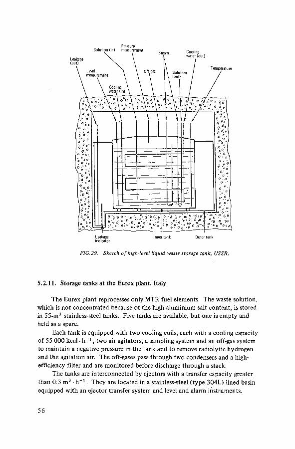
Pressure
ind ica tor
FIG. 29. Sketch of high-level liquid waste storage tank, USSR.
5.2.11. Storage tanks at the Eurex plant, Italy
The Eurex plant reprocesses only MTR fuel elements. The waste solution, which is not concentrated because of the high aluminium salt content, is stored in 55-m3 stainless-steel tanks. Five tanks are available, but one is empty and held as a spare.
Each tank is equipped with two cooling coils, each with a cooling capacity of 55 000 kcal • h - 1 , two air agitators, a sampling system and an off-gas system to maintain a negative pressure in the tank and to remove radiolytic hydrogen and the agitation air. The off-gases pass through two condensers and a high-efficiency filter and are monitored before discharge through a stack.
The tanks are interconnected by ejectors with a transfer capacity greater than 0.3 m3 • h - 1 . They are located in a stainless-steel (type 304L) lined basin equipped with an ejector transfer system and level and alarm instruments.
5 6

5.3. CONSTRUCTION
The integrity of the constructed vessels is ensured by a series of inspection and testing methods which are in turn documented and verified by a compre-hensive quality-assurance programme. This programme is varied, depending upon the effect unanticipated failure of the equipment might have upon either the public or the environment. Thus the stainless steels used in the fabrication of the high-level liquid waste storage tanks are accompanied by certification papers that document the material history as well as the results of any qualifying tests, such as corrosion tests, which were specified as required for each lot of metal during all stages of its fabrication. Furthermore, during fabrication of the tank, each weld is identified; all non-destructive tests such as dye penetrant, radiographic and/or ultrasonic tests of the weld, and the identity of the welder, are documented. Documentation for the welder includes a record of his training, results of his qualifying tests and other pertinent information such as a record of the rejection rate on welds fabricated by this welder. Conversely, non-critical installations such as steam lines used to heat the building that houses the secondary heat exchangers for cooling the waste tanks would normally be fabricated from the 'off-the-shelf pipe and pipe fitting, without additional quality-assurance documentation other than that normally provided by manu-facturers of these items. Equipment such as the high-level waste evaporator may require less quality-assurance documentation and testing if the design basis is for the evaporator to be replaceable if it is to remain operable throughout the plant lifetime. Repairs or alterations to equipment require quality-control tests and quality-assurance documentation equivalent to that required in its fabrication.
A particular feature of the design of recently constructed tanks is the absence of equipment or supports on the tank bottom or against the sidewalls, as well as the absence of penetrations through any wall except the top. For example, in the new Windscale tanks, the cooling coils and air-lift circulators are assembled separately with the top of the tank, which is attached to a portal framework. The complete unit is lowered into the tank and the framework rests on a specially prepared slab outside the tank to support the weight of the assemblies. In the Barnwell tanks the coils, ballast tanks, circulating jets and tank roof are supported by the reinforced tank sidewalls.
Smaller tanks up to 4 m in diameter, which can be readily transported to the site, are shop-fabricated. Larger tanks are usually field-fabricated on site, in place or near to their final location. Tanks are formed by welding stainless-steel plates that have been preformed to shape. Two or more plates are joined to make a ring. Rings are welded together, with longitudinal welds staggered. Horizontal tanks are fabricated with dished-end caps. Caps are fabricated by pressing triangular pieces of plate to shape and welding the pieces together.
57

Tops for vertical tanks are also fabricated from shaped plate. The top curvature is much less than that of the caps and therefore less preforming is required. With jacketed tanks, all welds on the primary tank are radiographed before the outer jacket is constructed. The integrity of the welds on the jacket is tested with dye penetrant.
Horizontal tanks are supported by saddles or beams which may be welded to the tank. Vertical tank bottoms are usually supported by beams or plates so that the stainless-steel liner beneath the tank can be flushed with water. Care should be taken in the design of support welds and joints to prevent excessive corrosion.
The need for concern regarding the effects of ground water was discussed in Section 5.1.2.
Appendix B lists UKAEA standard specification,and Appendix C lists waste storage tank construction specifications for Barnwell (USA).
5.4. INSPECTION, TESTING AND COMMISSIONING
The integrity of the constructed vessel is ensured by a comprehensive inspection procedure to the stringent standards as described in Appendices B and C. Inspection and testing of the completed vessels have become more stringent over the years. In early years, inspection included such tests as dye-penetrant crack detection and radiography of all welds followed by a water-pressure test of the complete vessel and system. In more recent years, the UKAEA has introduced ultrasonic testing of materials and, where possible, gas or vacuum leak tests on completed vessels. In the USA, ultrasonic testing has also been introduced where possible on materials and vessels. Gas or vacuum leak tests are also included where possible on complete vessels.
While it is not possible to pressure-test the outer cell cladding or to radio-graph the welds, all welds are inspected for leaks by the vacuum-box or dye-penetrant techniques.
All project work on the site is under the responsibility of a resident engineer who hands over the installed plant on completion to the operational staff. The latter will have had close contact with the resident engineer during the installation stage. The resident engineer should check:
Supply for each component; Procedures and qualifications of construction and welding personnel; Cleanliness of facilities and hardware; That the specifications for preparation and shaping of pieces to be
assembled are adhered to; Quality of welds (by radiography of all welds);
58

Accuracy of size; Finishing procedures; and Final testing (pressure and leak tests).
These checks are made at all times during construction and assembly, both in the outside workshops and on the installation site. Standard specifications are normally laid down, typical ones for the UKAEA are included in Appendix B and these apply to both evaporation and storage-tank facilities.
Final confidence that the new plant functions as designed is obtained during commissioning. Staff who are to operate the plant begin by checking that all pipe-runs, connections and plant are suitable for the specified task. This process begins with visual inspections and proceeds through testing, first with water, then nitric acid and simulated waste liquids. Volumes and transfer rates are calibrated. Operating conditions are verified and optimized.
Preliminary operating procedures are prepared prior to commissioning. These are verified and modified as necessary during commissioning and they form the basis for initial operation with radioactive materials and subsequent routine operation.
59

6. DESIGN OF ACCESSORIES FOR EVAPORATORS AND STORAGE TANKS
The safe and reliable handling, treatment and storage of high-level liquid wastes require detailed attention to all the accessories associated with both the evaporators and storage tanks. The two most important groups of ancillary items are involved with either transfer operations or with off-gas cleaning. To assist the smooth and safe operation of the equipment and processes, routine sampling, leak detection and instrumentation are also important and are studied in detail in this section.
6.1. TRANSFER AND FEED SYSTEMS
These constitute one of the most important operational aspects of the high-level waste system. Many megacuries are involved daily and it is imperative that this liquor should be handled and transferred safely without any leakage or spillage.
The main design criteria for the installation of equipment required to initiate the movement of highly active liquor are:
(a) It is desirable to have no moving parts. (b) Equipment must be installed behind shielding and be remotely operated. (c) There should be no requirement for maintenance; if this cannot be
avoided, it should be as low as possible, with access kept to the minimum by installing the equipment in a shielded bulge adjacent to the main plant.
(d) Transfer operations should be replicated, preferably using different systems.
6.1.1. Pipes and connections
Stainless steel is used almost exclusively for all pipes and connections, the latter usually being welded and radiographed. The layout of piping requires careful planning. Horizontal sections should be avoided, particularly if there is a risk of solids settling. Provision must be made for routine flushing of pipes after the transfer of liquor containing suspended solids as well as for the removal of any sediment if a transfer operation is suspended or as a result of any maloperation. Duplicate transfer lines should be installed for all the major transfer operations. Temperature control of transfer pipelines is very important, particularly for the transfer from the evaporator to the storage tank. A sudden drop in temperature could lead to excessive crystallization and blockage and a rise in temperature could lead to vapour locks during the transfer. Due attention
60

1. Vent i la t ion air in 5. Support saddle
2 . Vent i la t ion air out 6. Steel pipe
3. Containment pipe 7. Support plate
4. Transfer pipe
FIG. 30. Waste transfer lines, Eurochemic, Mol, Belgium.
should be paid to the siting of pipes externally to the main process areas (e.g. from one building to another), to allow for exceptional weather conditions such as severe frost or a prolonged period of hot weather. While the pipes will be contained within shielded tunnels, they must be adequately heated and/or cooled and the conditions monitored before the actual transfer takes place. All such transfer tunnels must be provided with containment for any possible leakage together with means of flushing, decontamination and replacement.
The containment of a transfer pipe within a second concentric pipe is a useful safeguard against leaks, provided that the outer pipe drains to an appropriate point and that provision is made for detecting and reclaiming any leak from the primary containment.
Figure 30 illustrates the cross-section through the waste transfer lines installed at Mol and it shows some of the above features. Heating or cooling is possible either by water or by air. Air is forced through the top pipe and returns through the outer steel pipe. When water cooling is required, cold water is circulated through the concentric pipes of the first and second containment.
6.1.2. Valves
These should be avoided on all the pipelines carrying high-level liquid wastes and on the immediate service lines associated with transfers. If there is a specific
61
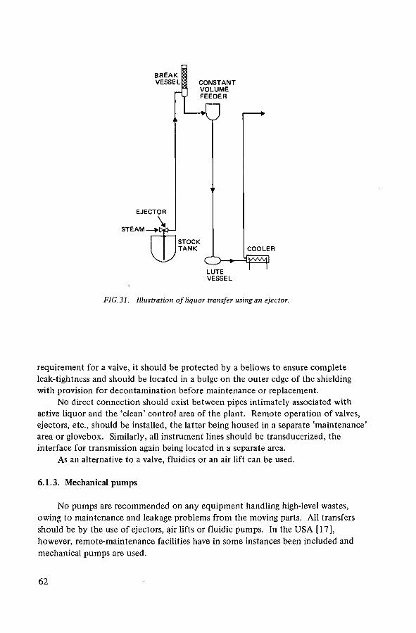
FIG.31. Illustration of liquor transfer using an ejector.
requirement for a valve, it should be protected by a bellows to ensure complete leak-tightness and should be located in a bulge on the outer edge of the shielding with provision for decontamination before maintenance or replacement.
No direct connection should exist between pipes intimately associated with active liquor and the 'clean' control area of the plant. Remote operation of valves, ejectors, etc., should be installed, the latter being housed in a separate 'maintenance' area or glovebox. Similarly, all instrument lines should be transducerized, the interface for transmission again being located in a separate area.
As an alternative to a valve, fluidics or an air lift can be used.
6.1.3. Mechanical pumps
No pumps are recommended on any equipment handling high-level wastes, owing to maintenance and leakage problems from the moving parts. All transfers should be by the use of ejectors, air lifts or fluidic pumps. In the USA [17], however, remote-maintenance facilities have in some instances been included and mechanical pumps are used.
6 2
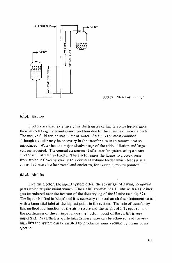
A I R SUPPLY-
V E N T
£ O z w O oc UJ S £0
VENT
< I -O I -
FIG.32. Sketch of an air lift.
6.1.4. Ejectors
Ejectors are used extensively for the transfer of highly active liquids since there is no leakage or maintenance problem due to the absence of moving parts. The motive fluid can be steam, air or water. Steam is the most common, although a cooler may be necessary in the transfer circuit to remove heat so introduced. Water has the major disadvantage of the added dilution and large volume required. The general arrangement of a transfer system using a steam ejector is illustrated in Fig.31. The ejector raises the liquor to a break vessel from which it flows by gravity to a constant volume feeder which feeds it at a controlled rate via a lute vessel and cooler to, for example, the evaporator.
6.1.5. Airlifts
Like the ejector, the air-lift system offers the advantage of having no moving parts which require maintenance. The air lift consists of a U-tube with air (or inert gas) introduced near the bottom of the delivery leg of the U-tube (see Fig. 3 2). The liquor is lifted in 'slugs' and it is necessary to instal an air disentrainment vessel with a tangential inlet at the highest point in the system. The rate of transfer by this method is a function of the air pressure and the height of lift required, and the positioning of the air input above the bottom point of the air lift is very important. Nevertheless, quite high delivery rates can be achieved, and for very high lifts the system can be assisted by producing some vacuum by means of an ejector.
6 3

FIG.33. Principle of the fluidic pump.

Air-lift systems are often used in highly active sampling systems, where small-volume transfers are required and where it is desirable to have little change to the concentration of the solution. It is worth noting that in environments where there is a possibility of sludge or precipitate formation, air-lift samplers should be operated continuously to prevent blockage at the bottom of the air-lift tube.
6.1.6. Fluidic pump
The fluidic pump (see Fig. 33) is based upon the use of a reverse flow diverter, which consists of two conical diffusers separated by a small interaction region forming a three-ported device. The interaction region becomes the pumping system inlet port and is connected to the storage vessel. The two conical diffuser outlet ports are connected to two gas pistons which are connected to an air controller. Connected across the reverse flow diverter is a two-input flow junction, the outlet of which constitutes the pump discharge line. The flow junction is a symmetrical 'Y' junction, specially designed for high efficiency. When flow enters either of the inlets, all of this flow passes to the outlet port. The junction acts as a rectifying element, converting the reciprocating action between the two gas pistons into a unidirectional flow into the discharge line.
In operation, liquor from the storage vessel initially charges the two gas pistons due to the hydrostatic head of the liquor in the vessel. Air pressure from the controller is applied to one gas piston while the other one is vented. Liquor is driven out of the gas piston into the junction of the reverse flow diverter inlet and the flow junction inlet. The liquor flow divides proportionally, one part flowing through the reverse flow diverter entraining liquor from the storage vessel to recharge the other gas piston, the other part flowing through the flow junction into the discharge line. When the gas piston is empty, the controller switches, venting the empty gas piston and pressurizing the charged gas piston. This oscillating drive and vent cycle results in a continuous flow of liquor being transferred from the storage vessel into the discharge line.
6.1.7. Constant volume feeder
This is the device most commonly used to transfer liquor at a specific flow-rate. It consists of a small vessel with a rotating device which has a number of cups of known volume (see Fig.34). As the unit rotates, the cups fill with liquor and are then emptied on further rotation. The flow-rate can be adjusted by the number and size of the cups and the speed of rotation. The motive unit is located in a bulge at the side of the process cell for easy access, but the actual constant volume feeder requires minimal maintenance. It is also possible, by regulating the hydro-static head over the opening, to use a feeding vessel from which a constant flow is obtained through a calibrated opening.
65

(Ts Os
FIG.34. Principle of the constant volume feeder.

FIG. 35. Flow diverter, Barnwell, USA.
6.1.8. Feed distributors
It is normal practice in a highly active liquor transfer system to install diverters for directing liquor to its prescribed source. They are used extensively and have proved to be reliable, requiring little maintenance. The design of the chemical plant should include these in preference to valves whenever possible. In the storage tank and evaporator facility they are used to receive the liquor from the reprocess-ing plant and to direct this liquor to one of many storage tanks or to the evaporator feed holding tank. The concentrate discharged from the evaporator is also directed to one of the storage tanks via a diverter. The diverter, which is vented, receives the input feed through the top, and by means of the rotating outlet the liquor is
67

routed to the selected outlet pipe, the solution flowing by gravity. Typical diverters installed in the nuclear industry range from a two-way diverter up to a twelve-outlet unit. A typical design of feed distributor or diverter, installed at the Barnwell plant, USA, is shown in Fig.35 [15].
6.2. OFF-GAS CLEANING SYSTEMS
Systems for cleaning the off-gases from waste-treatment and storage tanks vary greatly. All modern systems have condensers and some method for particulate removal, usually a filter. At some sites, gas-cleaning equipment is shared with the plutonium and uranium recovery plant, in which case an emergency system must be provided for the storage tanks. In any case, redundant gas-cleaning equipment must be available, for, when high-level liquid waste is in a storage tank, the gas-cleaning system must operate. Scrubbers, cyclones, electrostatic precipitators and iodine adsorbers may be added to improve the clean-up. Off-gas systems fall into the following categories:
(a) The condensation and off-gas system from the evaporator where the condensation load is high (there are very few non-condensables);
(b) The off-gas system on the tanks which has to remove small amounts of carryover (entrainment) from the air introduced into the tanks (the condensation load is low but the gas flow, which is mainly air, is large);
(c) A system that is adequate for any emergency situation.
The basic equipment required is in most cases similar and of conventional design. Some actual systems are described (Sections 6.2.6 and 6.2.7) to explain the general arrangement.
6.2.1. Condensers
All waste treatment systems require condensers. The condensate is sub-sequently treated as low-level waste solution. Often it is subjected to a second evaporation, with the bottoms or concentrate being recycled to the high-level waste evaporator; the distillate serves as part of the feed to the acid fractionator. Usually, the storage tanks have their own condenser; the condensate can either be returned to the storage tank or routed to the low-level waste treatment system. It is desirable to be able to regulate the concentration of the solution in storage. In very large tanks equipped with cooling coils, the initial transfers must be diluted to cover a sufficient number of cooling coils to control the temperature. Subse-quently this excess liquid must be removed; diversion of the tank condensate to waste treatment provides a means for removing this excess.
68

The condensers are usually single pass with welded tube sheets. Condensers can be either vertical or horizontal; if horizontal, sufficient slope must be provided for the condensate to drain free.
6.2.2. Scrubbers »
Scrubbers are often installed in the high-level evaporator off-gas line to remove entrained liquid.
In the case of the evaporator at Windscale, which is operated at 50-70 mmHg pressure, the condenser units on the two-stage steam ejectors act as further scrubbers for entrained activity. The remaining gases pass through a Peabody scrubber, which also serves the whole vessel vent system of the plant, before passing to the stack.
The Peabody scrubber, illustrated in Fig.36, consists of three impingement plates, spray headers and a water eliminator, arranged in a tall cylindrical vessel. Water for scrubbing and cooling the air is supplied to the top impingement plate, flows across it and across the successive plates by means of a system of down pipes and water seals, eventually falling to the base of the scrubber and passing through the water outlet. Each impingement plate consists of a perforated plate with individual baffles placed over and at a short distance from each hole. Although the baffles are submerged, water will not flow down through the holes in the perforated plate while there is a sufficient upward flow of air.
Contaminated air enters the base of the scrubber where water from the sprays saturates it and removes the larger solid particles. The air then rises through the impingement plates and at each stage is divided into many small jets which, in overcoming the tendency of the water to flow down through the perforations, tear away water droplets from the periphery of the hole. Impingement occurs between the solid particles and these droplets, and each air jet itself impinges upon a baffle. The velocity of impact drives the solid particles into the scrubbing water and breaks the air jets into innumerable bubbles which pass up through the water layer maintained on each impingement plate. The trapped solids are carried away by the water which flows counter-current to the gas stream. At each impingement plate, therefore, there is positive contact between the air and the scrubbing water.
The water eliminator at the top of the vessel consists of a series of overlapping vanes which remove any entrained moisture from the cleaned air before it leaves the scrubber. A stainless-steel centrifugal fan is fitted which extracts air at the rate of 2.6 m3' s"1 (5500 ft3' min -1) against a resistance of 1.27 m (50 in) water gauge.
In the Barnwell plant, USA, the evaporator overheads are combined with the dissolver off-gases and they pass through two mercury nitrate scrubbers which remove entrained liquid and iodine.
69

Air out le t
Water efrminator
Seal pot
Impingement baff le plate
Plate stage
Water inlet for sprays
Manhole for inspection
SYMBOLS
Air f l ow Water f l ow
Water inlet
A i r inlet
Water drain
FIG.36. Sectional elevation through Peabody scrubber, UK.
7 0

In France, the evaporation unit is connected to a scrubber where gases'are washed; this scrubber also acts as a recombination unit for nitrous fumes by the injection of oxygen. Storage tanks are connected to a gas-cleaning unit with a scrubber.
6.2.3. Electrostatic precipitators
These are only used in the United Kingdom. The precipitator consists of six cylindrical tubular receiving electrodes mounted vertically between two header vessels (see Fig.37). Inside each tube is suspended a central cruciform discharge electrode with serrated edges. The exhaust air enters the bottom of the lower header vessel and meets a diffuser which ensures equal distribution of the air through the six tubes. The cleaned air leaves the prcipitator through a duct in the side of the upper vessel. Spray pipes are fitted in the two header vessels for washing or decontamination. The electrode feeder passes through a central tube in the top of the upper header vessel and warm air is passed down this tube to avoid condensation and possible build-up of hydrogen or spread of contamination. The electrical supply is located above the shielding. Two precipitators are installed in parallel.
6.2.4. Iodine adsorbers
Concern in the USA about the discharge of 129I has required the addition of iodine removal equipment in off-gas systems. In the latest plant, iodine adsorbers are provided for this clean-up in both the waste evaporator and waste storage tank off-gas systems.
6.2.5. Filters
Usually the final off-gas treatment is one or more stages of filtration. High efficiency (HEPA) filters, packed beds and sand filters are those most often used. HEPA filters used for off-gases from waste systems are pleated fibreglass cloth, usually with a stainless-steel frame. These then fit into filter frames which are attached to the off-gas transfer lines. These filters will not tolerate large quantities of moisture, and therefore the system design should eliminate the bulk of the liquid entrained in the off-gas. Care must be taken to ensure that the filter fits snugly in the filter frame so that part of the gas does not bypass the filter.
A packed-bed filter consists of a bed of fibreglass or other inert media through which the gas must pass. The efficiency of this type of filter depends on the packing density, thickness of bed, mean diameter of the fibre, and the face velocity of the gas.
71

VIA S E A L V E S S E L
FIG.37. Section through electrostatic precipitator, UK.
7 2

Sand filters are beds of sand through which the gas is passed. The efficiency of this type of filter is dependent upon the bed thickness, the size of the sand particles, and the face velocity of the gas.
All filters require in-place samplers, to enable the efficiency of the filter to be determined. Use of 0.3-mm particles of dioctylphthalate (DOP) is one of the methods used in testing filter efficiency and for the correct installation of the filter in the frame.
Packed-bed and sand filters have the disadvantage of acting as accumulators of large quantities of radionuclides which must be properly disposed of when the filter is decommissioned. HEPA filters are replaced routinely and thus add to the routine radioactive solid waste that must be handled and disposed of.
6.2.6. Off-gas treatment systems for waste evaporation
The process off-gas treatment flowsheet for the high-level liquid waste concentration system at Barnwell, USA, including that for the evaporator, is shown in Fig. 38 (see pocket at inside back cover). The non-condensables from the high-level liquid waste concentration systems are combined with those from the dissolver off-gas, and the combined stream passes through the No. 1 iodine scrubber, which contains a recirculating mercury nitrate solution. The gas then passes to an N0 2 scrubber to remove nitrogen oxides. It is then combined with the off-gas from other vessels, passed through another mercury nitrate scrubber, a heater, a HEPA filter, a silver zeolite adsorber, two more stages of HEPA filtration, blowers and into a stack for discharge to the atmosphere. A sampler on the stack and corresponding analytical results provide records of discharges of radioactive material.
The simplified flowsheets of the evaporation systems at Windscale, UK [8, 13], and Tokai, Japan [16], are shown in Figs 7 and 13, respectively, and the French plant is illustrated in Fig. 8.
6.2.7. Off-gas treatment systems for waste storage tanks
The arrangement of the off-gas treatment system for a storage tank is shown in Fig. 19 for the new tanks at Windscale, UK [8, 13], The gaseous effluent from the tank is fed to two electrostatic precipitators, connected in parallel. One unit is on stand-by and is sealed from the air flow by a hydraulic seal pot. In the event of failure of the operating unit, the air supply to the tank is automatically shut off until manual changeover to the other precipitator has taken place. The power supply to the precipitators is covered by a diesel electric generator set. The air from the electrostatic precipitator is then fed to a packed scrubber through which cooled water is circulated. This,scrubber performs the dual purpose of additional decontamination while cooling the air to condense out any nitric acid vapour and thus
73

prevent condensation in the ventilation system. The condensed liquor passes to monitoring tanks for further effluent treatment. This unit is shielded in case of increased carry-over of activity, and the scrubber liquor can be diverted to standby tanks if necessary.
The off-gas system for the high-level liquid waste storage tanks at Barnwell, USA, shown in Fig.39 (see pocket at inside back cover) collects the off-gases from all the tanks,and channels them through a condenser and a knockout pot to remove condensables. Condensates pass through a diverter either to the waste tanks or to low-level liquid waste treatment. The system has a relief valve which protects the tanks and system against high pressure or vacuum. Non-condensables are normally added to the plant off-gases where the dissolver and process off-gases are combined. Thus it is treated by an iodine scrubber, iodine adsorber and three stages of HEPA filtration. Emergency off-gas treatment is also provided, to be used when the plant off-gas treatment system is shut down. This provides for an iodine adsorber and a HEPA filter. Discharge of normal and.emergency off-gas systems is through the plant discharge stack.
6.3. INSTRUMENTATION
Reliable instrumentation is an essential feature in the safe operation of all facilities handling and storing high-level wastes. All important instruments should be replicated, often with measurement by different techniques. Alarms and warnings should be provided to signal any abnormal situation and, if necessary, corrective action should be automatically activated. Instrumentation should also be installed to monitor the abnormal situation if it arises; for example, level instruments in the vault outside the storage tanks in case it fills with liquid. It may be useful to be able to observe the outside of the tank by television or other remote-viewing equipment. A brief description of the more important types of instrument follows.
6.3.1. Level measurement
A purge dip-tube system is commonly used for the measurement of level, particularly in waste storage tanks. A number of purge tubes are installed through the top of the tank, with the open ends of the tubes at different levels below the liquid. Those at the lowest level should be 50-100 mm from the bottom, the space being adequate to avoid any interference from sludge in the bottom. The installation should be such as to allow easy removal for inspection, cleaning or replacement. Air is passed at sufficient pressure to overcome the hydrostatic liquid head so that a steady stream of bubbles issues from the end of the dip-tube. A second air line terminates at the top of the tank. The difference in back pressure
74

between the two air purges is proportional to the depth of liquid above the tip of the purge tube. The accuracy is improved by having the probes at different levels.
Level indicators based on electrical contact through conductivity of solution between two electrodes are more likely to be faulty for boiling liquids and should preferably be avoided on evaporators.
A liquid level measurement device has been developed at the Idaho Chemical Processing Plant based on the electrical resonant properties of a coaxial chamber. The chamber selected consists of a stainless-steel pipe; the outer conductor is about 100 mm outer diameter, and the inner conductor about 25 mm outer diameter. A standard deviation of 0.02 mm testing measurement was determined during testing of this instrument. Instrument sensitivity is great enough to measure ripples from pneumatic probes 0.01 mm high.
Level measurement by ultrasonic techniques is also used.
6.3.2. Density measurement
The purge dip-tube system is also used for density measurement, but in this case two dip-tubes are used with the open ends at a known, fixed, vertical distance apart. The difference in hydrostatic head at the tube openings is proportional to the density of the liquid since the vertical distance is constant. A number of these probes are installed to indicate density at different levels. Other methods are also at the development stage.
6.3.3. Temperature measurement
The sensing element is normally a thermocouple, which is located in a suitable 'well' or pocket for protection. All important thermocouples used for operation and control should be duplicated and located at strategic positions to obtain the required temperature distribution pattern and, where possible, for ease of replace-ment. It is important to know the temperatures at different locations in the storage tanks, especially near the bottom, to detect possible hot spots due to sludge formation.
6.3.4. Acidity measurement
Measurement of acidity in the storage tanks is very important because cor-rosion will largely depend on the acidity of the solutions. Remote pH measurement, however, would be impracticable under existing conditions and is not very reliable. For these reasons acidity is measured on samples which can be taken at sampling stations located wherever necessary.
75

6.3.5. Pressure measurement
Conventional remote-transmitting pressure- and vacuum-measuring instruments can be used provided care is taken in siting them and they are protected from condensation or blocking of the lines. It should be possible to change the sensing element remotely if required.
6.3.6. Flow measurement
The flow of high-level activity liquids is very difficult to measure, particularly if there are suspended solids. Transfers may be made by constant volume feeders or a two-stage air lift system in which the flow-rate is controlled. Some direct flow-measurement techniques have been developed based on the ultrasonic or Doppler effect. Conventional techniques can be used for flow measurement on non-radioactive auxiliaries.
6.3.7. Hydrogen measurement
Determination of the hydrogen concentration in the space above the liquid in the storage tanks is essential. At present, the determinations are not very accurate, but methods are under development in several countries.
6.4. SAMPLERS
Complete control of the process cannot be obtained solely from in-line instrumentation, and some important information can be obtained only by taking samples of the solutions. This is the case, for example, for acidity, uranium and plutonium content, concentration of major fission products, etc.
Fairly standard procedures have been developed for routine sampling of highly active liquids. They are all based on the use of a loop that circulates the liquid so as to get a representative sample by avoiding the presence of stagnant liquid which could cross-contaminate a new sample. Circulation is often obtained by raising the liquid, by means of air lifts, into a sampling station from which the liquid will flow back by gravity to the vessel (see Fig.40). All materials used must withstand corrosion from the liquor environment to avoid any contamination of samples. The sampling station is normally installed in a small shielded cell adjacent to the main operating cells it will control and it is equipped with a viewing window and such equipment as is necessary to handle samples.
Samples are normally collected in a penicillin-type vial with a rubber stopper. In some cases the vial itself is part of the circulating loop. In others, the solution is transferred from the sampling pot by being sucked through hypodermic needles into pre-evacuated vials.
76

V A C U U M
FIG.40. System for sampling from fission-product tanks.
6.5. LEAK DETECTION
Leakage must be detected as soon as possible, especially when it occurs on one of the highly active circuits or tanks. It is most likely to be very small and great attention should be paid by the operators to early warning signs.
Leakage from a tank can be detected very early because of the contamination of the air inside the cell surrounding the tank, and this can be detected by in-line monitors or a rise in the level of the activity at the filters. At a later stage, liquid will flow to the receiving-pans under the tanks and a leak can be detected through electrical conductivity probes installed in the receiving pit. The installation of remote-visual techniques may assist in locating the position of a leak.
Radiation monitoring is difficult to use close to pieces of equipment con-taining large activities; it can, however, detect the appearance of radioactivity on process fluids that should normally be non-radioactive, such as heating or cooling water. This is true when pressure in the circuit does not prevent entry of contamination. When the circuit is pressurized, the leak can be detected through the increase of volume in the tank by using a sensitive level probe.
77

7. OPERATING EXPERIENCE
Highly active liquid raffinates from reprocessing irradiated fuel elements have been stored in stainless-steel storage tanks since 1953. (Experience in the USA with storing neutralized wastes in mild steel tanks dates from 1944.) Most of these solutions have also been subjected to evaporation to make the most efficient use of the storage capacity available. From 1953 to the present, this part of the nuclear fuel cycle, i.e. the evaporation and storage of highly active raffinates in liquid form, has been relatively trouble-free. The stainless-steel or titanium evaporators and stainless-steel storage tanks have proved reliable and safe, and typical design examples are described in Sections 4 and 5.
Much of this success has been the result of extensive laboratory-scale development work on the problems of concentrating high-level wastes, the effect of the acidity, temperature and concentration factor on the onset of crystallization and precipitation, and detailed studies of the corrosion of candidate construction materials in the environments likely to be found in both the evaporators and the storage tanks. The success of the various agitation devices is also the result of full-scale mock-up trials of the systems currently in use.
Sound operating practices are important for the safe and reliable operation of the facilities (see Section 9.3.2). Operating procedures must be reviewed periodically and improved whenever possible in the light of experience.
Operating experience arising from the evaporators and storage tanks are summarized as follows.
7.1. EVAPORATORS
7.1.1. Operation control
Both continuous and batch operation have been used for evaporators. French and United Kingdom experience is mainly with batch operation, although the Windscale evaporator is operated with continuous feed and batch discharge, whilst United States experience has been with continuous operation.
The evaporation rate is controlled by two means: the input liquor feed rate and the steam flow to the evaporator jacket or coils. It is essential to monitor and control both systems. Steam pressure and steam flow indication are normal requisites for good plant operation.
Evaporation is often carried out at reduced pressure to reduce the boiling point of the liquid and therefore limit corrosion to some degree. As mentioned in Section 4, this also safeguards against the reaction of tributyl phosphate and nitric acid.
78

The partial vacuum in the evaporator is normally obtained by a steam ejector which discharges into a water-filled seal pot. To maintain the vacuum on the evaporator it is necessary to ensure that the seal pot is sealed, and this is achieved by continuously adding water to the pot, which has a top overflow line to carry away the slightly warm water. This operation has proved successful and easy to operate.
In France, formaldehyde is added to destroy nitric acid and reduce the acidity, thus helping to limit corrosion. When an organic reagent, such as formaldehyde, is being used to destroy excess nitric acid, the reaction conditions must be adjusted so that the reduction will be kept under control and proceed smoothly. The initiation phase of the reaction is the one that requires greatest attention, and the addition of the formaldehyde must be adjusted to prevent the accumulation of unreacted reagent. Once the initiation phase has passed, the reaction is easy to control.
The off-gas system, comprising disentrainment, condensation, scrubbing, etc., associated with the operation of the evaporators has raised no problems, and decontamination factors of 106 are typical. Since the fuel is cooled for at least 90 days after removal from the reactor, there is no problem with 1311. The only other main volatile species is Ru04 , but the ruthenium usually tends to remain complexed with the nitric acid, unless subjected to excessively elevated temperature.
There is concern regarding the build-up of 129I in the environment. Because of its extremely long half-life ( 1.7 X 10⁷ years), its potential hazard is thought to be greater than its low reactivity might imply. Iodine clean-up equipment is therefore now required for off-gases which could contain 129I.
7.1.2. Feed control
The dilute liquor from the reprocessing plant is transferred to an evaporator feed vessel equipped with cooling coils. It is then often lifted to a constant volume feeder (see Section 6.1.7) which transfers the liquor at the required rate to the evaporator. A two-stage air lift can also be used for feed control. Operational experience with these devices has demonstrated their reliability over the years, from the point of view of both feed control and maintenance.
Although physical separation of the organic phase from the nitric acid aqueous phase is carried out in the reprocessing plant, in the United Kingdom the aqueous feed is passed through a steam strip column as a final solvent clean-up before entering the evaporator. In the USA and France, steam stripping is not adopted; these countries rely on good separation of the organic phase at source.
7.1.3. Transfer operations
The many possible devices for transfer of high-level liquids have been described in Section 6.1.
79

The most common methods of transfer, and those in which vast experience has been obtained, is the use of ejectors (steam, water or air operated) or air-lift systems. A vacuum-assisted transfer using an ejector can give rise to an air slug and therefore mist entrainment at the end of a batch transfer operation from one vessel to another. Wherever possible, a direct force-lift ejector transfer is preferable, with the ejector immersed in the liquor. The air-lift system requires a disentrainment vessel at its highest point and must be continuously operated to prevent blockage due to settling of fines at the air-lift foot position, i.e. the lowest point.
Main transfer operations should be at least duplicated and preferably be of dissimilar type.
7.1.4. Construction materials
Extensive corrosion studies have been carried out with simulated high-level liquid wastes to measure corrosion rates and determine the effect of operating variables such as temperature, acidity and solution composition and concentration, although the results of many studies have not been published. Stainless steel is widely used in most countries, but if the liquors contain sulphate or iron, titanium if often preferred. Titanium is very sensitive to fluoride corrosion and therefore titanium must not be used in solutions that contain any fluoride. Nitric acid solutions containing fluoride may arise from the reprocessing of some fast-reactor fuels and these present special corrosion difficulties. When using stainless steel with such solutions, the addition of aluminium to complex fluoride and the restriction of temperature to minimize corrosion have been practised.
Great care is taken in the design and operation of the evaporators to minimize corrosion and no instances have been reported of unanticipated corrosion problems in stainless-steel systems.
7.2. STORAGE TANKS
The storage of high-level liquid wastes in stainless-steel tanks has been practised for 25 years and the record during this period has been extremely good, with no incident of a leaking tank being recorded.
The most important consideration in the storage of high-level liquid wastes is to ensure that containment is not breached and that the following operating parameters are maintained at predetermined values to ensure that failure is unlikely:
(a) The acidity must be maintained at a level that produces minimum sludge formation and also limits the corrosion of the stainless steel;
(b) The temperature of the liquor in storage must be held below 60°—65°C (in many cases, temperatures are below 50°C);
80

(c) Any solids formed by precipitation or crystallization must be kept in suspension and prevented from settling on heat-transfer surfaces and on the tank bottom;
(d) All instruments measuring temperature, level, alarms on cooling-water circuits, etc., must be continuously monitored and regularly maintained.
7.2.1. Cooling system
Correct functioning of the cooling system is an essential feature of the operation and control of each storage tank. The contents of a tank can involve many megacuries of ^-activity and the initial fission-product decay heat will be equivalent to several megawatts. When a new tank is being brought into use after commissioning, it is usually partially filled with water or dilute nitric acid to ensure that enough of the heat-transfer surface is covered with liquid to remove the decay heat as the waste solution is fed into the tank. Once the normal operating level has been reached, in-tank evaporation is encouraged in order to remove some of the excess liquid, and the volume available is filled with fresh waste solution. Careful monitoring of the rate of addition of fresh waste is essential, together with the temperature and the heat removal through the cooling system. At no time must too much fresh liquor be added to exceed the cooling capacity of the tank. The operation of the cooling system, involving each cooling coil circuit as well as the outer jacket (if installed),must be monitored to ensure that design heat-transfer coefficients are being maintained; one of the early effects of excessive sludge formation in the tanks is a decrease in the heat-transfer coefficient.
The cooling systems are normally operated on a closed-cycle basis, with recirculation by pumps through secondary heat exchangers or, possibly, cooling towers. Make-up water is added to the system when necessary. It is important to ensure that the duplicate pumps are always operable and that the stand-by emergency power supply is available. The cooling system must be continuously monitored for 7-activity and, for reliability, should include two monitors in series. In addition, a high-level alarm should be installed. In the unlikely event of an alarm, the water supply to the circuit in question must be automatically shut off; normally, sufficient hold-up capacity would be available in the pipeline behind the shielding to compensate for the alarm-to-shut-off time-lag response. No difficulties have been experienced in operating the cooling systems, and there have been no recorded instances of significant environmental releases due to failures of cooling systems in stainless-steel storage tanks.
7.2.2. Corrosion data/sludge formation
One of the important sides of the routine surveillance of filled storage tanks is to monitor for corrosion. Since the sludges which are normal to the operation
81

of most tanks can settle and give rise to high localized temperatures, which will then enhance corrosion in the area, identification of the formation of sludges is also important. One such routine method is checking the heat-transfer coefficients of the cooling circuits, as discussed in Section 7.2.1. Other methods used are:
(a) Temperature recording: Direct thermocouple temperature recording is installed at different locations and levels in the tanks. While temperatures should be kept below 60°-65°C by means of the cooling system in order to minimize corrosion, any differences in temperature profile, particularly from top to bottom, will indicate sludge formation at the bottom of the tank.
(b) Cooling-water jacket: This is primarily to keep the temperature of the outer wall of the tank below 60°-65°C, particularly if sludge collects in certain areas of the tank bottom away from the agitation devices and the temperature recording points. The jacket is also a further containment device before the cell liner.
(c) Specimen samples: Samples of the material from which the tank was constructed are introduced directly into the tank at various depths in the liquor. These specimens should include welds typical of the main tank body. The specimen samples are removed at intervals for examination, and the design of the storage-tank facility should in'clude a shielded cell to carry out the necessary examination.
(d) Liquor sampling: Analysis of samples taken from the tank at various locations will give guidance for operational control of the acidity and thereby provide a means of controlling the type of precipitate which may be produced, depending on the acidity.
(e) High-level alarm: This should be located somewhat above the normal operating level to give warning of any unexpected volume increase, which may originate from a leaking cooling coil as well as from an erroneous transfer to the tank concerned. This alarm will alert the operation staff who will be able to take the necessary action. Very often the alarm will activate an automatic device, allowing remedial actions similar to those discussed in Section 7.2.1.
7.2.3. Sparging and pulsing
The devices required to recirculate the contents of the tank have been described in Sections 3 and 5. The ballast tanks are operated in turn in the storage tank so that the bottom is scoured by a jet of liquor every few minutes. The air lifts provide further means of agitation and recirculation, but, most important,
82
they assist the rate of evaporation. The alternative method of obtaining evaporation is to pass hot air over the surface of the tank and thus avoid passing air through the liquor.
With the new storage tank at Windscale, UK, it was observed that as the specific activity of the liquor increased, there was a disproportionate increase in the rate of loss of nitric acid by radiolysis when the air-lift circulators were in use. At specific activities above about 6 Witr - 1 , the acid reduction stage of the evaporator cycle could be omitted and the acidity of the concentrate controlled at the optimum 1 —2N by suitable division of the in-tank evaporation load between the air-lift circulators (with simultaneous evaporation and radiolytic nitric acid loss) and surface evaporation (during which radiolysis is negligible). However, there is an adverse consequence of omitting the acid reduction step in the evaporator because the concentrate fed to the tank will contain mono- and di-butyl phosphates that have not degraded to inorganic phosphates. These result in foam formation in the tanks if air agitation is used. By suitable modification of the operating procedure in the evaporator and by avoiding the use of the air-lift circulators for a period immediately after the addition of a fresh batch to the tank, this effect has been eliminated.
Radiolysis in highly active waste solutions will cause some hydrogen produc-tion. Sparging by air tends to increase this effect by altering the equilibrium reached in static solutions. The air sparging sweeps the hydrogen in a diluted form into the off-gas system, and a separate air purge of the off-gas may be added for further dilution of the hydrogen. Sparging with an inert gas, such as nitrogen, may afford some additional safety. However, all forms of sparging tend to entrain droplets of waste solution, and this increases the load on the off-gas treatment system. As a final precaution, the determination of hydrogen in the gas space above the liquor in the storage tank is advocated (see Section 6.3.7).
It has been calculated for the Barnwell, USA, storage tanks that if, during a failure of the air purge, the tank temperature is allowed to rise to 85°C, which takes about three hours when the tank is loaded to its design heat-removal capacity, the vapour pressure of water is sufficient to maintain the atmosphere over the liquor surface above the flammable hydrogen limit, assuming maximum radiolytic decay and hydrogen generation.
Owing to the large size of storage tanks now used, simple air sparging through perforated pipes has not proved as efficient as air pulsing or mechanical lifting and recycling the liquor contents, and the latter methods are preferred.
7.2.4. Sampling
The highly active liquid in the storage tanks has a density of about 1.3 g-cm - 3 , and, since the tanks are usually located below ground level, it is normal to lift the liquor to a higher position in order to take a sample from an intermediate pot,
83
using a hypodermic needle. The design of sampling systems is described in Section 6.4. The lift can be carried out by many devices. However, steam- or water-operated ejectors will dilute the sample, and air-operated ejectors tend to form aerosol mists. The preferred method is to use an air lift, vacuum-assisted if necessary, and this allows remote operation and requires minimal maintenance. The direct hypodermic needle sampling also involves minimal maintenance and is accepted world-wide as a good operational standard procedure. Such sampling of highly active liquors has proved very successful, but it will not necessarily give any indication of sludge formation.
7.2.5. Transfer operations
The same methods can be used as for the operation of the evaporators (see Section 7.1.3).
84
8. SHIELDING
All facilities handling high-level radioactive solutions require extensive shielding to reduce the radiation levels to acceptable levels. The storage tanks are often sited partially or completely below ground so that the earth provides some of the shielding. However, to protect the tanks from environmental or other damage (flood, earthquake, aircraft crash, etc.) they must be contained within heavy reinforced concrete structures that provide both radiation shielding and physical protection (see also Section 9.2). Thickness of shielding generally ranges from 1.5 m to 2.4 m.
The design of shielding is based on standard methods which are described in the literature [22, 23], and the shielding thicknesses will depend on the 7-flux and energies concerned, with allowance for self-shielding.
Each evaporator and tank or group of tanks will normally be located in its own shielded enclosure or cell with the ancillary equipment in a separate area where the radiation levels may be several orders of magnitude lower and where limited access for maintenance may be possible. All liquor transfer devices, sampling stations, etc., would be located in shielded bulges on the outside of the main shielding. Such practices are now standard for all plants handling high levels of activity. Overall plant layouts and shielding depend on whether a no-maintenance or a remote maintenance philosophy is adopted (see Section 3.11). In the latter case, the design may be more complex owing to the additional remote-handling equipment and viewing windows required. Attention must be paid to the detailed shielding design if much operator time is required at the working face to ensure that personnel exposures do not exceed acceptable levels.
85

9. SAFETY
Safety is a prime requirement in dealing with the very large quantities of radioactive materials that are involved when the highly active effluents from a reprocessing plant are to be concentrated and stored as liquids. Enough experience has been accumulated in several plants throughout the world to ensure that a very high level of safety can be achieved, and present practices have been described in preceding sections. The present section is not a full safety analysis but is intended to recall the guidelines to be kept in mind when designing and operating a high-level liquid waste treatment plant.
Safety concerns are of two main types:
Safety during normal operations; and Consideration of abnormal situations that may cause release of radio-active species into the environment.
9.1. SAFETY DURING NORMAL OPERATION
Irradiation of personnel is of very great concern owing to the presence of large amounts of 7-emitters in the solutions. It will depend upon the nature of the fuel, the burnup and the cooling time before reprocessing, but activities are always very large.
Shielding against radiation is provided by installing items of equipment in concrete cells. It is essential to place in separate cells those items of equipment where access may be required for maintenance, so as to reduce the exposure of personnel to a minimum. Any piece of equipment that will not by itself be a source of radiation should be installed outside the cells if possible; if it may become radioactive under unlikely circumstances then it must be shielded.
Contamination is also a very important potential danger, mostly through the presence of long-lived a- and 0-emitters. Contamination is contained by building several successive confinement areas separated by barriers. The vessel itself is the first area, and a dynamic confinement barrier can be added by keeping the vessel under negative pressure wherever possible. The concrete cell, with its stainless-steel lining, is a second confinement area, and sometimes the building may be a third.
As a protection against both irradiation and contamination, vessels containing radioactive solutions must have under them a receiving pan that will hold any leakage and from which leakage can be transferred to appropriate receivers. The concrete cells housing the storage tanks will be lined with stainless steel to such a height that it will form an inner tank able to collect at least the volume of the largest tank in the cell.
86

Radiolysis of the solutions gives rise to hydrogen evolution which in turn presents a potential risk of explosion in enclosed spaces in contact with air. This may be prevented by dilution by sweeping air over the liquor surface, as indicated in Section 7.2.3. Radiolysis may also destroy nitric acid and increase the pH of the solution, leading in some cases to precipitation of solutes. This can be detected through regular sampling and analysis and counteracted by the addition of nitric acid. Radiolysis will frequently accelerate chemical reactions, and this effect should be anticipated.
Self-heating of the solutions is induced by radioactive decay and if not controlled could present a hazard, especially if the solutions come to boiling temperature. (The Exxon, USA, tanks are designed for self-boiling.)
The main function of the cooling equipment is to prevent continued boiling of the solutions under their own thermal power. As this could give rise to serious problems, the equipment must be made safer by replicating both the cooling systems and the supply of cooling water.
Corrosion will be kept within acceptable limits if materials of the appropriate characteristics and thicknesses are used. Evaporators and storage tanks are the pieces of equipment most sensitive to corrosion, and in the case of storage tanks they must be able to withstand corrosion for long periods until their contents can be transferred to a solidification plant. Corrosion can be minimized if solutions are kept at sufficiently low temperatures (50—65°C), and this is achieved through cooling systems, both with coils inside the tanks and jackets on the outside.
The quality of construction must be of the highest, with control of stainless-steel grades and radiography of all welds. It is advisable to reduce to a minimum sharp bends or angles on surfaces and pipes, as well as on pipes passing through walls; this is especially true for the bottom of the evaporators and tanks, as these areas could be submitted to heat and enhanced corrosion if precipitates, which should be suspended in the liquid, deposit there.
As a general protective measure, it is also common practice to have spare tanks available at all times for the transfer of solution from a faulty tank.
Sedimentation may cause hot spots and increased corrosion, as discussed in Section 7.2.2. This can be minimized by sparging and by the control of acidity.
9.2. SAFETY IN ABNORMAL SITUATIONS
Criticality is a very limited risk, as the uranium and plutonium have been separated earlier in the process and it can be eliminated if the fissile-material content is checked prior to concentration.
Equipment failure may lead to the loss of essential items such as cooling equipment, air sparging, off-gas cleaning, etc. This possibility should be foreseen in the design and back-up equipment. Alarm systems should be provided.
87
The loss of cooling is the greatest concern of this type, and requires special attention in design and operation. Provision must be made for replicated cooling systems of extremely high reliability with diversity and adequate built-in stand-by facilities. More details are given in Section 7.2.1.
Corrosion can be accelerated by local heating, addition of improper chemicals, or construction errors, as well as other causes, and this can result in unexpected leaks. The design of equipment should provide for detection of leaks and their containment, as previously described.
Although the probabilities of external incidents are very small, such events as an earthquake or an aircraft crash must be taken into consideration and their consequences evaluated. The critical parts of the facility will be constructed to withstand these events as anticipated for the particular site. Consideration of aircraft crashes should include damage from both impact and fire.
When the evaporation process includes the use of an organic reagent (e.g. formaldehyde) for the destruction of the nitric acid, there is a risk of a violent reaction that could lead to dispersion of active materials. Methods of preventing this are discussed in Section 7.1.1. The reaction of tributyl phosphate with nitric acid is also potentially a safety concern, as discussed in Sections 4 and 7.1.1.
Although there is a limited potential risk of fire, the consequences may be so severe that extreme care must be taken for its prevention. Preventive measures include minimizing the use of combustible materials and provision of early detection equipment and extinguishers.
Operating errors can lead to abnormal situations as described above. The minimization of errors by means of automation and procedural control is discussed in detail in Section 9.3.
9.3. METHODS OF PREVENTION OF POTENTIAL RISKS
An ideal situation from the point of view of safety would be one where the flowsheet is such that risks are virtually eliminated. This is not possible because of the very nature of the risks described above. However, it is important when choosing the processes to balance the potential risks and to select solutions that minimize the probabilities of accidents, especially those which could occur in the long term.
When inherent safety can be built into the process through construction, flowsheet and/or automation, it is advisable to do so.
88

9.3.1. Built-in safety
9.3.1.1. Design and construction
The design of the facilities and the quality control of construction are essential features to eliminate the risks of irradiation and contamination. This point was elaborated in the preceding parts of Section 9 and in several other sections.
Design should provide for emergency situations. This could be achieved by redundancy of critical equipment, keeping in mind that an excess of redundancy could make the operations too complex. The storage tanks must also be protected against elevated or abnormally reduced pressures.
An emergency source of power must be available at all times to provide electricity, water, steam and air if the main supplies are deficient. It is advisable to relay all information that is important for safety to an outside building in the plant area so that it would still be available if that part of the plant should be evacuated.
9.3.1.2. Process procedures
Once the equipment has been designed and built with the above safety objectives in mind, it is also essential to analyse and select procedures which are inherently as safe as possible. The following criteria may be followed:
Choose the simplest procedure that is suitable; Identify the critical steps where complete control of the operations is
necessary, such as start-up of a new batch, initiation of formaldehyde reaction with nitric acid, etc.;
Define the controls that are necessary both in-line and from samples; Try to keep the number of transfers and sampling operations to a minimum; Use a working temperature as low as practicable.
9.3.1.3. Automation
Safety may be greatly increased by using automatic devices so that, whenever possible, it is not necessary to rely on operator intervention. The simplest type of automation is the alarm that will signal a defect in operation. Such alarms are installed on level, density, pressure, temperature and activity measurements and in other ways. It is also possible to identify sequences of events that would create a potential hazard and to interlock controls in such a way as to prevent these situations from occurring. Finally, the use of data processors can give the operators a quicker and better knowledge of essential process information.
89

9.3.2. Operating safety
In addition to a maximum of built-in safety features, the overall safety of the operations will rely on good use of the equipment by competent and well-trained operators. Complete standard procedures must be established which fully describe all steps of the operations. These procedures must cover what has to be done in normal operations and establish what must be done in abnormal situations and at which level of responsibility. Qualification of operating personnel is very important; this may be achieved through the initial selection of operators and their subsequent training so that they have complete knowledge of the equip-ment, the procedures and the way to use them.
9.4. CONTROL OF SAFETY
9.4.1. Process instrumentation
Process instrumentation is installed to indicate that the operating parameters are correct, and its proper function is of the utmost importance for the safety of the plant. When choosing a type of instrumentation, reliability must often be preferred to accuracy or precision if the latter is not absolutely necessary.
9.4.2. Radiological instrumentation
This is used as a control of the radiation levels to which workers can be exposed at given locations in the plant. It can also be used for monitoring circuits and checking the level of activity, as is the case, for example, when the occurrence of radioactivity in an auxiliary circuit will indicate a leakage from an active solution.
9.4.3. Personnel exposure
Control of personnel exposure is the ultimate and most direct check for the safety of the operators, and exposures should normally be well under the accepted limits.
9 0

10. ENVIRONMENTAL PROTECTION
Contamination of the environment due to the release of activity can lead to serious consequences. The criteria for selecting sites for high-level liquid waste storage will initially be similar to those for the reprocessing plant. It is probable that, in most countries, the high-level liquid waste will be solidified within a few years of reprocessing. However, if a solidification process is not available, the liquid could remain in storage for long periods, even after the reprocessing plant operations have ceased, in which case additional environmental factors may have to be considered.
Site selection studies must include evaluations of the ecology, geology, topo-graphy, hydrology, seismology, meteorology and the properties of the local soil if we are to be certain that the environment can tolerate the strains that will be placed upon it by the plant. Equally important, the plant structures and equipment must be able to withstand natural hazards such as hurricanes, tornadoes, earthquakes, floods, that can be expected at a given site. These studies determine the stresses which the design must withstand. It is imperative that high-level liquid wastes be confined within the process equipment and the storage tanks, so the design of such equipment and tanks for these wastes must resist these stresses. Obviously, sites which have a high probability of serious earthquakes or massive flooding should be avoided.
Most of these environmental factors apply equally to the process plant and the waste systems. However, there are some unique factors to be considered with regard to liquid waste and the soil properties, hydrology and geology. These are considered below.
10.1. ENVIRONMENTAL FACTORS
10.1.1. Soil studies
Although a design objective is to isolate the liquid waste from the environment, it is prudent to evaluate probable migration routes and the rate of migration if radioactive liquid should be released from confinement. Representative samples of the soils in the area should be tested for permeability and ion-exchange properties so that the migration rate of specific radionuclides can be determined. If the surrounding soils are porous, then naturally occurring clays such as bentonite, montmorillonite, clinoptilolite may be placed between the structure and the soil to form an effective barrier against migration. Bentonite is available in large sheets nearly 2 cm thick, and one layer can form an effective barrier if the edges between sheets are overlapped or suitably bonded.
91
10.1.2. Hydrology
Hydrological evaluations will reveal the location of aquifers and the movement of underground water. These studies, when combined with the soil studies, will make it possible to predict the pattern of migration of radionuclides. The studies will require extensive drilling of test wells in the area, many of which will be retained as part of the operational hydrological monitoring programme. In decommissioning test wells, care must be taken to make certain that an abandoned well does not form a connection between aquifers which were previously isolated from each other. Such a reconnection could alter the hydrology and the water table and change previous evaluations. Generally preferred practice is to install liquid-waste storage tanks above the upper water table. This not only prevents direct leakage into the aquifer but also prevents seepage of water from the aquifer into the structure.
The hydrology of the site can be a very critical matter if wells are the source of water for cooling the waste tanks. The aquifers must be able to provide the required quantity of water under all conditions. Early in the evaluation, pump-down tests should be run to determine the effect on other users of the aquifer. Excessive draw-down indicates that the aquifer may not be a reliable source of water.
One very important part of the hydrological studies is determination of the quality of the water that will be obtained from production wells. Well water can range from highly acidic to highly alkaline and from essentially none to very many dissolved solids. Water quality will dictate the construction materials and the type of water conditioning required.
10.1.3. Ground water
Ground water includes all surface water such as lakes, streams, rain water run-off and swamps. The most likely media for transport of radionuclides into the environment is through run-off of rain water which has contacted mildly contaminated surfaces, and therefore control of run-off requires considerable attention. It is good practice to cover the soil adjacent to the waste-treatment and storage structures with concrete or asphalt to prevent percolation of rain water into the subsurface near these structures. Drainage ways are generally provided to separate the run-off from areas that have a potential for contamination from the run-off from areas that contain no radioactive materials, such as the utilities. It is also good practice to divert potentially contaminated run-off to holding ponds so that samples can be taken and analysed to verify the absence of contamination. Such holding ponds provide for limited hold-up and allow time for treatment if contamination should be discovered.
92

Secondary cooling-water systems for liquid waste storage are usually equipped with a closed-loop cooling tower or spray pond with once-through cooling as a back-up system at some sites. Where water is plentiful, e.g."beside a large river or lake, once-through cooling is used throughout. In either case, the water being discharged must be monitored for radionuclides and non-radioactive chemicals which could harm the lake, stream or ocean into which the water is to be discharged. At most sites, the temperature of the water must approach ambient before it can be discharged. A holding pond, which provides sufficient time for the water to reach equilibrium, is the usual method of meeting these requirements. Routine samples and analysis provide the data for verification that discharges are within permissible limits.
10.1.4. Geology
The geology of the area must be investigated to make certain there is sufficient strength in the soil to support the massive structures associated with liquid waste processing and storage and to predict the magnitude and frequency of seismic disturbances. Variations in foundation designs can accommodate large variations in the underlying media. Thus structures can be constructed on such widely varying media as rock and sand, with equal assurance of safety.
One problem associated with the storage of high-level liquid waste must be considered: heat that is transferred from the storage structure owing to the absorption of 7-radiation by the structure will reduce the moisture content of the soil adjacent to all sides of the structure. In certain soils, this drying process could result in unacceptable differential settlement and thus could result in failure of the structure. Replacement of the soil immediately adjacent to the structure with a sand that is unaffected by changes in moisture will solve this problem.
10.2. ENVIRONMENTAL MONITORING
Effective environmental monitoring requires that a comprehensive assessment of the environment be made prior to construction of the facility. This should include sufficient understanding of the ecology of the area for early warning of adverse effects on the environment to be obtained. For example, the thyroids of animals concentrate iodine, so the release of very small quantities of radioactive iodine can be detected; pine needles and certain willow trees allow early detection of the release of caesium. It is important to identify those plants and animals in the area which can give this early warning, and they should be selected for routine monitoring.
Non-condensable off-gases from waste treatment and storage are usually combined with those from the uranium and plutonium recovery processes and are
93

discharged from an elevated stack. Stack height is based on the meteorology and topography of the site.
It is often convenient to calculate the concentration at site boundary using the following factors: stack height, distance to the site boundary, volume of gas (air) being discharged, average meteorological condition, wind direction (x, y and z components), temperature, etc., to obtain an average dispersion X/Q (s'rrT3) for the site boundary. This value when multiplied by the quantity of a radionuclide being released continuously per second gives a calculated concentration of that nuclide at the site boundary.
At a site with no predominantly prevailing winds, an average X/Q dispersion of about 2 X 1CT8 s-m"3 at 2.5 km from the discharge point will be obtained from a 100-m stack. A stack height is generally selected to give X/Q within an order of magnitude of this value. Stacks are equipped with monitors to measure particulates and iodine, as well as other materials generated in the recovery process. In addition, samples of selected plants, animals and fish are obtained routinely to detect any breakdown of confinement of radionuclides. Fall-out collectors are scattered throughout the areas. These collectors are counted routinely to back up the results of the stack monitors.
Water samples from monitoring wells, conditioning ponds, rain-water run-off collection ponds, rivers or lakes nearby are analysed routinely.
9 4

11. CONCLUSIONS
This report has surveyed the status of the technology for evaporation and tank storage of the high-level liquid wastes arising from reprocessing irradiated nuclear fuel that require cooling, certainly for the early periods of storage.
Twenty-five years have elapsed since the first stainless-steel storage tanks came into operation, and during this period experience has been good. The technology exists for the design, construction and operation of solidification processes which have reached the pilot and demonstration stage, but are not yet in routine operation. It will therefore be necessary for the current practice of liquid storage to continue for some time, and past experience gives confidence in the acceptability of this decision. No incidents or leaks have been reported when using the technology described in this report, and it is clear that the design of the systems has many in-built safeguards to ensure guaranteed containment until solidification becomes widely practised.
95

VAPOUR HEADER
DISENTRAINER PADS
PRIMARY CONDENSER
COOLING »WATER
STEAM FEED FROM UNDERGROUND
STORAGE TANK TO FILTERED VESSEL VENT SYSTEM
' i
SLURRY PRODUCT TO UNDERGROUND STORAGE TANK
EMERGENCY SLURRY DUMP TO EMERGENCY RECEIVER TANK
JET VACUUM SYSTEM
TO SURFACE POND
CONDENSATE COLLECTION
TANK
I T PROCESS R E S I N - 1 CONDENSATE B E D L TO TRENCH
ION EXCHANGE COLUMN
FIG.41. Vacuum evaporator-crystallizer (from Ref. [24]).

Appendix I SPECIALIZED EVAPORATION SYSTEMS
While this report is primarily concerned with the evaporation and storage of high-level liquid wastes, it would not be complete without mention of various specialized evaporators that have been used to concentrate high-level liquid wastes to free-flowing slurries which either solidify on cooling or are used as concentrated feed for some of the solidification processes being developed. In the United States of America, a vacuum evaporator-crystallizer has been used at Hanford, and a bent-tube evaporator is currently used at Savannah River to concentrate these wastes for storage as soluble, retrievable salt cakes. However, wiped-film evaporators are being considered as possible replacements and they have also been used to provide a concentrated feed to various solidification processes currently being developed as part of Battelle's Waste Fixation Programme.
1. VACUUM EVAPORATOR-CRYSTALLIZER
Over 75 000 m3 (20 million US gal) of HALW from which the heat-producing radionuclides 90Sr and 137Cs were separated have been concentrated using a forced-circulation evaporator shown in Fig.41 [24], During operation, the 91 m3
(24 000 US gal) of slurry in the evaporator are circulated at 0.88 m3 • s_1 ( 14 000 US gal per minute) through a 0.7 m (28 in) diameter recirculation loop by an in-line pump. Process heat for the evaporation is supplied by steam in the shell side of the reboiler and the evaporator is maintained at operating temperature and pressure of about 60°C (140°F) and 0.056 kgf-cm"2 (0.8 lbf-in - 2 (a)) respectively. The liquid level is controlled by the removal rate of the slurry.
Radioactive feed, a combination of dilute waste liquor and recycled con-centrated liquor, enters the circulating slurry stream between the pump and the reboiler at 6 .3-7.6 Itr-s"1 (100-120 US gal per minute). The slurry passes through the reboiler, and 2.5-3.15 ltr• s"1 (40—50 US gal per minute) of water are evaporated at the liquid surface in the evaporator. The vapour passes through two wire-mesh disentrainment pads to the primary condenser. A two-stage steam jet ejector system maintains the vacuum in the unit.
The evaporated and condensed water is routed through an ion-exchange column into underground cribs, while the slurry, which contains up to 30 vol% crystalline solids, returns to the underground storage tanks. After a suitable settling period in the tanks, the concentrated liquor is pumped from them. First, the free liquor at the top of the tank is removed by floating suction pumps, and this is followed by additional liquor recovery by pumps embedded deep in the salt cake. Thé damp salt cake is considerably less mobile than the original liquid waste.
97
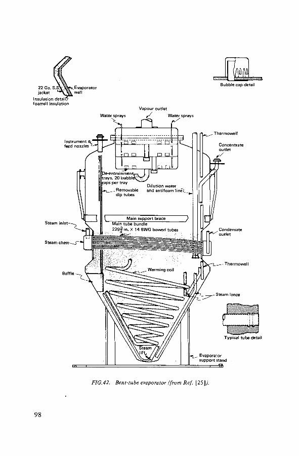
22 Ga. S.S jacket
Insulation detail} foamsil insulation
Evaporator wall
Bubble cap detail
Water sprays
Thermowell
Steam inlet
Steam ches t^J~* j
Baffle
Evaporator support stand
fi>
FIG.42. Bent-tube evaporator (from Ref. [25]).
98

TABLE II. COMPOSITION OF WASTE SOLUTIONS
Solution molarity Decladding waste Purex waste HM process waste
NaAIOî 2.3 0.55 0.84
N a N 0 3 1.4 3.4 4.6
NaNOj 0.64 - 2.2
NaOH 2.3 0.30 0.5
Na2 S 0 4 - 0.08 0.11
Na 2 CQ 3 - 0.35 -
The unit was designed for a decontamination factor of 106, based on the radionuclides in the slurry and radionuclides in the condensate, but values have averaged nearer 108.
2. BENT-TUBE EVAPORATOR
The detail of this unit is shown in Fig.42 [25]. It has been used to concentrate three basic types of waste, as given in Table II.
The decladding waste is ideal for concentration. The aqueous solution contains no solid phase at its boiling point and a large difference exists between the boiling point of the solution and the temperature at which a solid phase is precipitated. When this solution is concentrated by a factor of 3.4 the hot concentrate is fluid, and a solid phase appears only when the solution is cooled 60 degC below its boiling point. The concentrated waste solidifies completely when cooled to room temperature.
The Purex waste is more difficult to concentrate. When concentrated by more than a factor of 2.5 the solution contains a solid phase at the boiling point. The solid phase is initially a sandy white precipitate of sodium carbonate and sulphate; sodium nitrate is also crystallized as the solution is concentrated further or is cooled. When concentrated by more than a factor of about 3, the solution contains a large amount of solid phase at the boiling point. However, the con-centrate does not solidify completely while cooling to 23°C; about one-third remains liquid. Although further concentration can produce a material that will solidify completely on cooling, the amount of solids present near the boiling point is too high to be handled in the bent-tube evaporator without causing plugging. A four-stage flowsheet is used for the concentration and
99
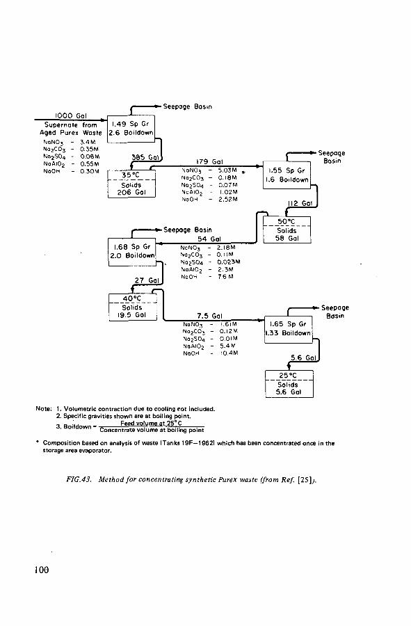
Note: 1. Volumetric contraction due to cooling not included. 2. Specific gravities shown are at boiling point.
Feed volume at 25°C 3. Boildown 1 Concentrate volume at boiling point
Composition based on analysis of waste (Tanks 19F—1962) which has been concentrated once in the storage area evaporator.
FIG.43. Method for concentrating synthetic Purex waste (from Ref. [25]).
100

Steam
Support Bearing
Support Beorina
Vapour
Product
Thermowells
Product
FIG.44. Preliminary designs of prototype vertical wiped-film evaporators, Savannah River, USA. (a) Artisan Industries; (b) Votator Div. of Chemetron Corp. (From Ref. [25].;
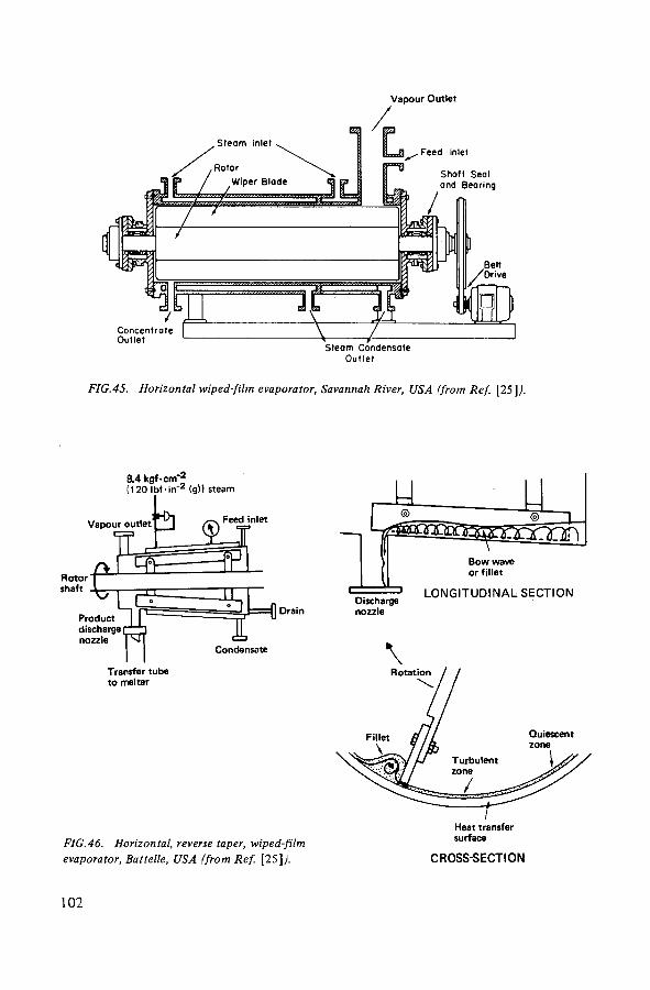
Vapour Outlet
Out l e t
FIG.45. Horizontal wiped-film evaporator, Savannah River, USA (from Ref. [25]).
8.4 kgf-cm-;* (120 Ib f - i r f 2 (g)) steam
Vapour outlet' ' . Feed inlet
J i = Q Drain
Condensate
FIG.46. Horizontal, reverse taper, wiped-film evaporator, Battelle, USA (from Ref. [25]/
Discharge nozzle
L O N G I T U D I N A L SECTION
CROSS-SECTION
102
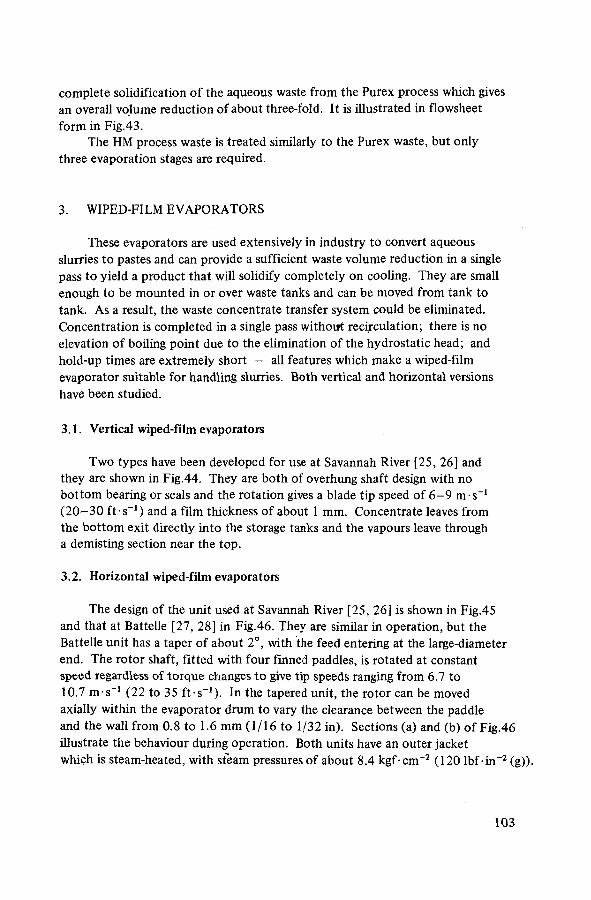
complete solidification of the aqueous waste from the Purex process which gives an overall volume reduction of about three-fold. It is illustrated in flowsheet form in Fig.43.
The HM process waste is treated similarly to the Purex waste, but only three evaporation stages are required.
3. WIPED-FILM EVAPORATORS
These evaporators are used extensively in industry to convert aqueous slurries to pastes and can provide a sufficient waste volume reduction in a single pass to yield a product that will solidify completely on cooling. They are small enough to be mounted in or over waste tanks and can be moved from tank to tank. As a result, the waste concentrate transfer system could be eliminated. Concentration is completed in a single pass without recirculation; there is no elevation of boiling point due to the elimination of the hydrostatic head; and hold-up times are extremely short — all features which make a wiped-film evaporator suitable for handling slurries. Both vertical and horizontal versions have been studied.
3.1. Vertical wiped-film evaporators
Two types have been developed for use at Savannah River [25, 26] and they are shown in Fig.44. They are both of overhung shaft design with no bottom bearing or seals and the rotation gives a blade tip speed of 6 - 9 m-s - 1
(20 -30 ft s - 1 ) and a film thickness of about 1 mm. Concentrate leaves from the bottom exit directly into the storage tanks and the vapours leave through a demisting section near the top.
3.2. Horizontal wiped-film evaporators
The design of the unit used at Savannah River [25, 26] is shown in Fig.45 and that at Battelle [27, 28] in Fig.46. They are similar in operation, but the Battelle unit has a taper of about 2°, with the feed entering at the large-diameter end. The rotor shaft, fitted with four finned paddles, is rotated at constant speed regardless of torque changes to give tip speeds ranging from 6.7 to 10.7 m-s 1 (22 to 35 ft• s~1 ). In the tapered unit, the rotor can be moved axially within the evaporator drum to vary the clearance between the paddle and the wall from 0.8 to 1.6 mm (1/16 to 1/32 in). Sections (a) and (b) of Fig.46 illustrate the behaviour during operation. Both units have an outer jacket which is steam-heated, with steam pressures of about 8.4 kgf-cm"2 (120 lbf-in - 2 (g)).
103
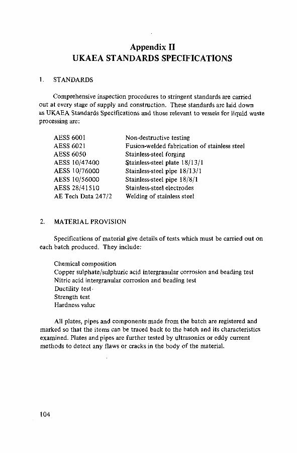
Appendix II UKAEA STANDARDS SPECIFICATIONS
1. STANDARDS
Comprehensive inspection procedures to stringent standards are carried out at every stage of supply and construction. These standards are laid down as UKAEA Standards Specifications and those relevant to vessels for liquid waste processing are:
AESS 6001 AESS 6021 AESS 6050 AESS 10/47400 AESS 10/76000 AESS 10/56000 AESS 28/41510 AE Tech Data 247/2
Non-destructive testing Fusion-welded fabrication of stainless steel Stainless-steel forging Stainless-steel plate 18/13/1 Stainless-steel pipe 18/13/1 Stainless-steel pipe 18/8/1 Stainless-steel electrodes Welding of stainless steel
2. MATERIAL PROVISION
Specifications of material give details of tests which must be carried out on each batch produced. They include:
Chemical composition Copper sulphate/sulphuric acid intergranular corrosion and beading test Nitric acid intergranular corrosion and beading test Ductility test-Strength test Hardness value
All plates, pipes and components made from the batch are registered and marked so that the items can be traced back to the batch and its characteristics examined. Plates and pipes are further tested by ultrasonics or eddy current methods to detect any flaws or cracks in the body of the material.
104

Appendix III BARNWELL (USA) SPECIFICATIONS
1. WASTE STORAGE TANKS CONSTRUCTION SPECIFICATIONS
In general, according to ASME Code, Section III, Division 1, Subsection NC, Class 2, except for tank roof, bottom and bottom knuckle, which cannot be designed in accordance with the Code and therefore shall be designed in accordance with methods of analysis mutually agreed upon by the Engineer and the Contractor:
The design basis shall be in accordance with Section III, Division 1, Sub-section NC, Class 2, for Class 2 components except for the external elements and internal bracings which shall be designed in accordance with the AISC Manual of Steel Construction, 7th Edition (1970) with Supplements 1 and 2.
The tank materials shall be in accordance with ASME Code, Section II, Part A or identical ASTM Specifications noted in the applicable ASME Specification.
The welding material shall be in accordance with ASME Code, Section II, Part C or identical AWS Specifications noted in the applicable ASME Specifications.
Chemical analysis and delta ferrite determination of welding materials per ASME Code, Section III, Division 1, Subsection NC.
Non-destructive Examination per ASME Code, Section V, as noted: Radiographic Examination per Article 2 Ultrasonic Examination per Article 5 Liquid Penetrant Examination per Article 6 Visual Examination per Article 9 Leak Testing per Article 10
Welding Qualifications per ASME Code, Section IX. Quality Assurance/Quality Control Systems per ASME Code, Section III,
Subsection NA. For Detecting Susceptibility to Intergranular Attack in Stainless Steels,
ASTM-A262.
2 MATERIAL SPECIFICATIONS
Stainless Steel, type 304L per ASME Code, Section II, Part A, or identical ASTM Specifications noted in the applicable ASME Specification.
Plate to SA240, Tp 304L Shapes to SA479, Tp 304L Seamless Pipe to S A312, Tp 304L Seamless Fittings to SA403, WP 304L
105

Titanium Alloys per ASME Code, Section II, Part B. Plate to SB265 Seamless Pipe to SB337 Bars to SB348 Seamless Fittings to SB363
ASME Code - ASME Boiler and Pressure Vessel Code, Latest Edition with Addenda.
AISC - American Institute of Steel Construction, Inc.
AWS — American Welding Society, Latest Edition with Addenda.
ASTM — American Society for Testing and Materials, Latest Edition.
106

Appendix IV SPECIFICATIONS OF MATERIALS USED FOR
FABRICATION OF EVAPORATORS AND STORAGE TANKS
1. UKAEA GRADE 18/13/1 STAINLESS STEEL - AESS (NF) 10/4740
Cr Ni C Nb Si Mn S P W Cu Mo Ti
Min % 17.5 12.0 - >10xc - 1.0 - - - - - -
Max % 19.5 14.0 0.1 1.3 0.8 1.5 0.04 0.04 0.3 0.3 0.2 0.05
2. FRENCH MATERIALS
C Si Mn Cr Ni S P Mo
Z2 CND 1 7 - 1 2 < 0 . 0 3 0 < 1 < 2 1 6 - 18 1 0 - 14 < 0 . 0 3 0 < 0.045 2 - 3
Z2 CNS 1 8 - 1 4 < 0 . 0 2 0 3 - 4 . 5 < 2 1 6 - 19 1 2 - 14 < 0 . 0 3 0 < 0 . 0 4 0
3. USSR MATERIAL
CT Ni Mn S P C Ti
Min % 17.5 9.5 0.1 - - 0.03 0.6
Max % 18.0 10.0 0.3 0.05 0.05 0.1 1.1
4. AISI TYPE 304L
Cr 18.5; Ni 9.5%; Max C 0.03%.
5. W-No. 1.4306 corresponds to DIN X2 Cr Ni 189 (FRG) Z3CN 18-10 (France) AISI-304L (USA) X 3 C N 1 9 11 (Italy)
107

Chemical composition: Max C 0.03%; Cr 18.5%; Ni 10.5%. The material 1.4306 from which the WAK (Karlsruhe) tanks are made has the following composition:
C 0.02%; Cr 18.5%; Ni 11.0%; Si 0.43%; Mn. 0.74%; Mo 0.07%
6. URANUS 65
Cr 25%; Ni 20%; Fe 54%; Mn + Si 0.8%.
108
DEFINITION OF TERMS USED IN THE REPORT
Ballast tank
(Also called jet sparge unit, ballast tube, jet ballast tank, pulsator.) An agitation device used inside a storage tank to keep particulate matter in suspension and minimize settling on the bottom of the tank. (See Section 3.7 for description and Fig.4 for illustration.)
Burnup
The energy obtained per unit mass of fuel, expressed generally as MW-d-t"1.
Cell liner
(Also called vault liner, catch tray, pan.) All vessels, such as storage tanks, to contain highly active liquids are located in concrete cells, the inside walls of which are lined with stainless steel which is welded to the same standards of leaktightness as the tanks themselves. This lining forms a container or catch tray and is of sufficient volume to hold the entire contents of the vessel in case of a leak.
Concentration factor
The ratio of the volume of dilute feed entering the evaporator to the volume of concentrated solution leaving the evaporator (generally transferred to the storage tank). When applied to the storage tanks, it is the ratio of the volume of solution entering the tank to the final volume in the tank after in-tank evaporation.
Diverter
A device used to direct liquor to the required place in the plant. For example, to direct the concentrate from an evaporator to any one of a group of storage tanks, a diverter is used. (See Section 6.1.8 for a description and Fig. 35 for an illustration.)
Duplication
The provision of two pieces of equipment (not necessarily identical) to perform the same operation. Generally one is in use and the other is always available as a spare.
Dye-penetrant technique
A test to detect surface flaws on weld metal in which a dye is used which penetrates into the surface defects, making them visible.
109

HEPA filter
A high-efficiency particulate filter, usually made front pleated paper, to remove fine suspended particles from a gas stream.
Leakage
This term includes the liquor leaking out of or into a vessel containing radio-active liquor. It can include water leaking from a cooling coil (situated inside a vessel) into the radioactive liquor as well as radioactive liquor leaking into the secondary containment, such as the cell liner, or into an outer secondary jacket.
Pulsing
The forcing of liquid by air pressure out of the jet at the bottom of a ballast tank to keep particulate matter in suspension. The air pressure is then reduced and the ballast tank refills with solution for the cycle to be repeated (see ballast tank).
Replication
The provision of at least two, generally more, pieces of equipment, preferably of different type, to perform the same operation. Sometimes necessary for important transfer operations or measurements.
Sparging
The bubbling of air (or inert gas) through a solution to keep any particulate matter in suspension and prevent settling.
Thermosyphon evaporator
An evaporator equipped with an external reboiler in which the liquor is heated. This results in a natural recirculation of liquor in a closed loop between the evaporator vessel and the reboiler by a thermosyphon action (for an illustration see Fig.6).
Vacuum-box technique
A leak-rate test in which a box is welded round the weld to be tested and a vacuum is applied to the box to exert a pressure on the weld area.
110

REFERENCES
[ 1 ] INTERNATIONAL ATOMIC ENERGY AGENCY, Management of Radioactive Wastes f rom the Nuclear Fuel Cycle (Proc. Symp. Vienna, 1976), IAEA, Vienna (1976).
[2] INTERNATIONAL ATOMIC ENERGY AGENCY, Storage Tanks for Liquid Radioactive Wastes: Their Design and Use, Technical Reports Series No. 135, IAEA, Vienna (1972).
[3] INTERNATIONAL ATOMIC ENERGY AGENCY, Tefchniques for the Solidification of High-Level Wastes, Technical Reports Series No. 176, IAEA, Vienna (1977).
[4] INTERNATIONAL ATOMIC ENERGY AGENCY, Characteristics of Solidified High-Level Waste Products, Technical Reports Series No. 187, IAEA, Vienna (1979).
[5] USERDA, Alternatives for Managing Wastes from Reactors and Post-Fission Operations in the LWR Fuel Cycle, Rep. ERDA 7 6 - 4 3 , 5 Volumes (1976).
[6] KOLYCHEV, B.S., "Reprocessing and burial of radioactive wastes formed in the regeneration of spent fue l " (in Russian), Proc. Ist CMEA Symp. Research on Reprocessing of Spent Fuel, Marianské LáznS, 1971, Vol. 1, p. 44.
[7] FOMIN, V.V., et al., Basic problems of regeneration of spent fuel rods f rom nuclear power stations (in Russian), At. Ehnerg. 43 (1977) 481.
[8] CLELLAND, D.W., "Concentration and storage of highly-active wastes f rom the first stages of the United Kingdom civil nuclear power programme", Treatment and Storage of High-Level Radioactive Wastes (Proc. Symp. Vienna, 1962), IAEA, Vienna (1963) 63.
[9] REDON, A., MAMELLE, J., CHAMBON, M., GIRAUD, B., "Gestion des déchets radioactifs de haute activité (produits de fission)", Nuclear Power and its Fuel Cycle (Proc. Int. Conf. Salzburg, 1977) 4, IAEA, Vienna (1977) 143.
[10] INTERNATIONAL ATOMIC ENERGY AGENCY, Regional Nuclear Fuel Cycle Centres (Rep. of IAEA Study Project) 2, IAEA, Vienna (1977), Section 13, Waste Management.
[11] LENNEMANN, W.L., "Management of radioactive aqueous wastes f rom US Atomic Energy Commission's fuel reprocessing operations, experience and planning", Management of Radioactive Wastes f rom Fuel Reprocessing (Proc. Symp. Paris, 1972), OECD/NEA, Paris (1973) 357.
[12] MENDE, H., Development and current technical status of decontamination evaporators, Kerntechnik 1 6 ( 1 9 7 4 ) 4 .
[13] WARNER, B.F., et al., "Operational experience in the evaporation and storage of highly-active fission-product wastes at Windscale", Management of Radioactive Wastes from Fuel Reprocessing (Proc. Symp. Paris. 1972), OECD/NEA, Paris (1973) 339.
[14] CLELLAND, D.W., "High level radioactive waste management in the United Kingdom", ibid., 233.
[15] LEGLER, B.M., BRAY, G.R., "Concentration and storage of high-level liquid waste at Allied-General Nuclear Services", Radioactive Wastes from the Nuclear Fuel Cycle, AIChE Symp. Series, No. 154, Vol. 72 (1976) 102.
[16] NAKAJIMA, K., "Management of fuel reprocessing wastes in Japan" , Management of Radioactive Wastes from Fuel Reprocessing (Proc. Symp. Paris, 1972), OECD/NEA, Paris (1973) 299.
[17] KONDRAT'EV, A.N., KHODOS, M.A., KHONIKEVICH, A.A., "Choice of special equipment for reprocessing of WWR reactor fuel rods using extraction technology" (in Russian), Proc. 1st CMEA Symp. Research on Reprocessing of Spent Fuel, Marianské Lázn?, 1971, Vol. l , p . 172.
[18] LAKEY, L.T., WHEELER, B.R., "Solidification of high-level radioactive wastes at the Idaho Chemical Processing Plant", Management of Radioactive Wastes from Fuel Reprocessing (Proc. Symp. Paris, 1972), OECD/NEA, Paris (1973) 731.
I l l

[19] SPITZYN, V.l., et al., "Technical and economic aspects of handling intermediate- and high-activity liquid wastes", ibid., 259.
[20] Atomic Science and Technology in the USSR (in Russian), Atomizdat, Moscow (1977) 159.
[21] GOODLETT, C.B., Transfer of Radioactive Slurries, USAEC Rep. DP-1136 (1968). [22] INTERNATIONAL ATOMIC ENERGY AGENCY, Reactor Shielding, Technical
Reports Series No. 34, IAEA, .Vienna (1964). [23] (ROCKWELL, T., III, Ed.), Reactor Shielding Design Manual, McGraw-Hill, New York
(1956). [24] PETRIE, J.C., et al., Vacuum evaporator-crystallizer handles radioactive waste, Chem.
Eng. Prog. (April 1976) 65. [25] GOODLETT, C.B., "Concentration of aqueous radioactive waste with wiped-film
evaporators", Radioactive Wastes f rom the Nuclear Fuel Cycle, AIChE Symp. Series, No. 154, Vol. 7 2 ( 1 9 7 6 ) 111; also USDOE Rep. DP-MS-75-17 (1975).
[26] GOODLETT, C.B., Concentration of aqueous radioactive waste, Chem. Eng. Prog. (April 1976) 63.
[27] DIERKS, R.D., BONNER, W.F., "The performance of a wiped-film evaporator with simulated high-level waste slurries", Radioactive Wastes f rom the Nuclear Fuel Cycle, AIChE Symp. Series, No. 154, Vol. 72 (1976) 123.
[28] DIERKS, R.D., BONNER, W.F., Wiped-film evaporator for high level wastes, Chem. Eng. Prog. (April 1976) 61.
112

LIST OF PARTICIPANTS
Advisory Group on the Safe Handling and Storage of High-Level Liquid Radioactive Wastes Requiring Cooling
CZECHOSLOVAKIA
Malasek, E. Czechoslovak Atomic Energy Commission, Slezská 9, Prague 2
FRANCE
Fisher, C.* Division de la chimie, Centre d'études nucléaires de Fontenay-aux-Roses, BP N° 6, F-92260 Fontenay-aux-Roses
GERMANY, FEDERAL REPUBLIC OF
Pollanz, H. Deutsche Ges. zur Wiederaufarbeitung von Kernbrennstoffen (DWK),
Büntweg 2, D-3000 Hanover 71
INDIA
Sunder Rajan, N.S. High Level Waste Management Section, Bhabha Atomic Research Centre, Bombay
JAPAN
Kusano, T. Processing Division, Tokai Works, Power Reactor and Nuclear Fuel Development Corp., Tokai-mura, Naka-gun, Ibaraki-ken 3 1 9 - 1 1
SWEDEN
Hultgren, A. (Chairman) AB Atomenergi, Studsvik, S-61101 Nyköping
* Consultant; assisted the Secretariat in preparing the draft of this document for review by the Advisory Group.
113

UNION OF SOVIET SOCIALIST REPUBLICS
Agienkov, A.T. State Committee on the Utilization of Atomic Energy, Staromonetnyj 26, Moscow
UNITED KINGDOM
Bailey, G.* UK Atomic Energy Authori ty, Dounreay Nuclear Power Development Establishment, Thurso, Caithness, Scotland
UNITED STATES OF AMERICA
Ayers, A.* Allied-General Nuclear Services, P.O. Box 847, Barnwell, South Carolina 29812
ORGANIZATIONS
COMMISSION OF THE EUROPEAN COMMUNITIES (CEC)
Dutailly, L. Health and Safety Directorate, Jean Monnet Building, Plateau Kirchberg, Luxembourg
EUROCHEMIC
Demonie, M. Eurochemic, B-2400 Mol, Belgium
INTERNATIONAL ATOMIC ENERGY AGENCY (IAEA)
Grover, J.R. Division of Nuclear Safety and (Scientific Secretary) Environmental Protection,
IAEA, P.O. Box 590, A-1011 Vienna, Austria
* Consultant ; assisted the Secretariat in preparing the draft of this document for review by the Advisory Group.
114

OBSERVERS
FRANCE
Cantel, J. Compagnie générale des matières nucléaires (Cogéma),
Route Nationale 186, F-92357 Le Plessis-Robinson
UNION OF SOVIET SOCIALIST REPUBLICS
Romanovskij, V.N. State Committee on the Utilization of Atomic Energy,
Staromonetnyj 26, Moscow
UNITED KINGDOM
Wood, A.G. British Nuclear Fuels Ltd.,
Risley, Warrington, Cheshire WA 3 6AT
UNITED STATES OF AMERICA
Hyder, M.Lee E.I. Dupont de Nemours & Co.,
Savannah River Laboratory,
Aiken, South Carolina 29801
115

HOW TO ORDER IAEA PUBLICATIONS An exclusive sales agent for IAEA publications, to whom all orders
and inquiries should be addressed, has been appointed in the following country:
UNITED STATES OF AMERICA UNIPUB, 345 Park Avenue South, New York, N.Y. 10010
In the following countries IAEA publications may be purchased from the sales agents or booksellers listed or through your major local booksellers. Payment can be made in local currency or with UNESCO coupons.
ARGENTINA
AUSTRALIA BELGIUM
C.S.S.R.
FRANCE
HUNGARY INDIA
ISRAEL ITALY
JAPAN NETHERLANDS
PAKISTAN POLAND
ROMANIA SOUTH AFRICA
SPAIN
SWEDEN
UNITED KINGDOM U.S.S.R.
YUGOSLAVIA
Comisión Nacional de Energfa Atómica, Avenida del Libertador 8250, Buenos Aires Hunter Publications, 58 A GlppsStreet, Colllngwood, Victoria 3066 Setvice du Courrier de l'UNESCO, 112, Rue du Trône, B-1050 Brussels S.N.T.L., Spálená 51, CS-113 02 Prague 1 Alfa, Publishers, Hurbanovo námestie 6, CS-893 31 Bratislava Office International de Documentation et Librairie, 48, rue Gay-Lussac, F-75240 Paris Cedex 05 Kultura, Bookimport, P.O. Box 149, H-1389 Budapest Oxford Book and Stationery Co., 17, Park Street, Calcutta, 700016 Oxford Book and Stationery Co., Scindia House, New Delhi-110001 Heiliger and Co., 3, Nathan Strauss Str., Jerusalem Librería Scientif ica, Dot t . Lucio de Biasio "aeiou". Via Meravigli 16,1-20123 Milan Maruzen Company, Ltd., P.O. Box 5050, 100-31 Tokyo International Martlnus Nljhoff B.V., Lange Voorhout 9-11, P.O. Box 269, The Hague Mirza Book Agency, 65, Shahrah Quaid-e-Azam, P.O. Box 729, Lahore-3 Ars Polona-Ruch, Céntrala Handlu Zagranicznego, Krakowskie Przedmiescie 7, Warsaw llexim, P.O. Box 136-137, Bucarest Van Schaik's Bookstore (Pty) Ltd., P.O. Box 724, Pretoria 0001 Universitas Books (Pty) Ltd., P.O. Box 1557, Pretoria 0001 Diaz de Santos, Lagasca 95, Madrid-6 Diaz de Santos, Balmes417, Barcelona-6 AB C.E. Fritzes Kungl. Hovbokhandel, Fredsgatan 2, P.O. Box 16358 S-103 27 Stockholm Her Majesty's Stationery Office, P.O. Box 569, London SE1 9NH Mezhdunarodnaya Kniga, Smolenskaya-Sennaya 32-34, Moscow G-200 Jugoslovenska Knjiga, Terazije 27, POB 36, YU-11001 Belgrade
Orders from countries where sales agents have not yet been appointed and requests for information should be addressed directly to:
§ ^ Division of Publications § f International Atomic Energy Agency ° ^ ^ Kärntner Ring 11, P.O.Box 590, A-1011 Vienna, Austria 0>

HIGH LEVEL LIOUIO WASTE STORAGE TANK
HIGH LEVEL LIQUID WASTE NO. 2 STORAGE TANK
ROTARY DIVERTER
HLL/ ILL WASTE STORAGE TANK
ROTARY OIVERTER
INTER« LEVEL LIQUID WASTE STORAGE
TANK
HIGH LEVEL LIQUID WASTE TANK HIGH LEVEL LIQUID WASTE HIGH LEVEL LIQUID HIGH LEVEL LIQUID WASTE WASTE OFF-GAS OFF-GAS OFF-GAS SUPERHEATER WASTE OFF-GAS OFF-GAS FILTER
CONDENSER K.O POT IODINE ABSORBER
25SZZ>
TO GENERAL PURPOSE CONC. FEED TANK
g S t
GENERAL SYMBOLS/ABBREVIATIONS
— IN-LINE MIXER
INSTRUMENT SYMBOLS/ABBREVIATIONS
# ft H — INSTRUMENT CONTROL AIR ELECTRICAL SIGNAL
CWS — COOLING WATER SUPPLY CWR — COOLING WATER RETURN NC — NORMALLY CLOSED STM — STEAM COND — CONDENSATE
ORGANIC STREAM AQUEOUS STREAM
X X X AIR SPARGER AIR LIFT HEAD POT
' (UNLESS OTHERWISE NOTED)
- Ä - I -FO
• A I R | |
CONTROL VALVE FO= FAIL OPEN FC : FAIL CLOSED FL : FAIL LOCKED Fl = FAIL INDETERMINATE
A/S
(psv!
SOLENOID
ROTAMETER
RESTRICTION ORIFICE
O - LOCAL MOUNTED
Q — PANEL MOUNTED
AIR LIFT
i - SAFETY RELIEF VALVE
INSTRUMENT ABBREVIATIONS ARE IN GENERAL AGREEMENT WITH ISA STANDARDS.
FIG.39. Waste tank off-gas treatment, Barnwell, USA.

OlSSOLVER OFF-GAS CONOENSER
OlSSOLVER Of"F-GAS K . O. POT
NO. I KXHNE SCRUBBER
DISSOLVER OFF-GAS VACUUM BREAKER
NO 2 ABSORBER NO. 2 IODINE SCRUBBER
O F F - G A S HEATER (STM)
O F F - G A S HEATER (BACK-UP ELECT)
O F F - G A S BLOWER K.O. POT
STACK
FROM DISSOlVERS
INSTRUMENT SYMBOLS/ABBREVIATIONS
0 H / / — INSTRUMENT CONTROL AIR — ELECTRICAL SIGNAL
1 t — CONTROL VALVE F 0 F0= FAIL OPEN
FC = FAIL CLOSED FL : FAIL LOCKED Fl : FAIL INDETERMINATE
H I H É b « - SOLENOID
ROTAMETER
COND. — CONDENSATE
INSTRUMENT ABBREVIATIONS ARE IN GENERAL AGREEMENT WITH ISA STANDARDS.
& Í
O e
- SAFETY RELIEF VALVE
— RESTRICTION ORIFICE
— LOCAL MOUNTED
— PANEL MOUNTED
FIG.38. Process off-gas treatment, Barnwell, USA.

TO LAW CONC. FEED TANK
GENERAL SYMBOLS/ABBREVIATIONS
ORGANIC STREAM AQUEOUS STREAM
X X X AIR SPARGER AIR L IFT HEAD POT (UNLESS OTHERWISE NOTED)
AIR u — AIR LIFT
• — IN LINE MIXER
CWS — COOLING WATER SUPPLY CWR — COOLING WATER RETURN NC — NORMALLY CLOSED STM — STEAM COND — CONDENSATE
INSTRUMENT SYMBOLS/ABBREVIATIONS
ff f f f f — INSTRUMENT CONTROL AIR ELECTRICAL SIGNAL
I I — CONTROL VALVE FO
K 3
FO - FAIL OPEN FC - FAIL CUDSED FL = FAIL LOCKED Fl = FAIL INDETERMINATE
- SOLENOID A/S
> — — i - ROTAMETER
— i — SAFETY RELIEF VALVE
<§H r
O e — RESTRICTION ORIFICE
— LOCAL MOUNTED
— PANEL MOUNTED
INSTRUMENT ABBREVIATIONS ARE IN GENERAL AGREEMENT WITH ISA STANDARDS.
TO SUMP COLLECTION TANK
< 4 : :
< 5 TO HLLW DIVERTER
HAW CONCENTRATOR HAW CONCENTRATOR H WW CATCH TANK HWW SAMPLE TANK RE BOILER CONDENSER
FIG. 10. High-level liquid waste concentration flowsheet, Barnwell, USA.

I N T E R N A T I O N A L SUBJECT GROUP: 11 A T O M I C ENERGY A G E N C Y Nuclear Safety and Environmental Protection/Waste Management V I E N N A , 1979 PRICE: US $14.00