Embed Size (px)
Citation preview

HAM RADIO WORKS
www.hrw.3dn.ru
APCO25/DMR/NXDN/YAESU SYSTEM FUSION
Stand alone
Digital Voice Receiver
ADCR25_PRO2
Manual ver 3.4 * the real receiver view can be different from the shown at the ad picture

1. Description and technical characteristics
ADCR25_PRO2 is fully stand alone digital voice receiver from antenna to audio path. To receive digital voice only antenna, USB power and headphones needed. Its windows compatible control software can work on any PC with installed Windows XP, 7, 8 and higher. In stand alone mode it can decode digital voice, do P25 trunk tracking and memory scanning. You can use your ADCR25_PRO2 in your vehicle for P25 trunk tracking, memory scan or conventional voice channel listening: simple plug the USB power via standard cell phone charger.
No special requirements to PC resources because software performs control
functions only. Any cheap and simple NetBook with free USB port will work with!
Due to on-board digital voice decoder the best digital audio quality provided compared to the PC software DV decoders. All critical algorithms are performed by special Digital Signal Processor with very fast memory access and ultra fast cache.
Electrical specifications:
DC power voltage from 3.5 to 5.5VDC; DC Current consumption 150mA max;
Receiver specification:
Sensitivity better than -116dBm; Adjacent channel rejection -60dB; Blocking performance -90dB; Frequency band: VHF version: 140-160 MHz and 164-190MHz UHF version: 410-480MHz 800M version: 820-960MHz
I/O connections:
Mini USB port for power and control; SMA female antenna connector; 3.5mm audio stereo jack; Dimensions: 65 x 45 mm

2. PC connection and control software running.
Before running control software please install Microsoft .NET version 2.0. If you are running under MS Windows 7 and higher you don’t need this.
Before connecting your ADCR25_PRO2 to PC please install Virtual COM Port VCP driver (comes with ADCR25_PRO2 software archive) from Driver_COMPORT folder (run CP210xVCPInstaller_x86.exe in case of WIN32 or CP210xVCPInstaller_x64.exe otherwise). ADCR25_PRO2 uses SiLabs CP2103 USB to COM converter. For the latest drivers and support please visit website:
http://www.silabs.com/products/mcu/Pages/USBtoUARTBridgeVCPDrivers.aspx
Attention! Install VCP driver BEFORE ADCR25_PRO2 USB connection!
After successful driver installation run control software p25recv-v5.3.exe and connect your
ADCR25_PRO2 to any free USB port.
Your receiver is ready to work after green LINK: <serial ESN> <FW ver.> appears.
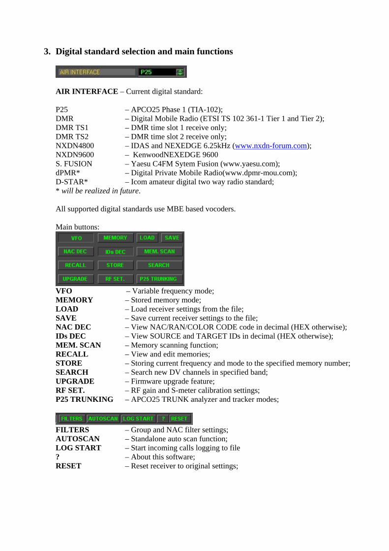
3. Digital standard selection and main functions
AIR INTERFACE – Current digital standard:
P25 – APCO25 Phase 1 (TIA-102); DMR – Digital Mobile Radio (ETSI TS 102 361-1 Tier 1 and Tier 2); DMR TS1 – DMR time slot 1 receive only; DMR TS2 – DMR time slot 2 receive only; NXDN4800 – IDAS and NEXEDGE 6.25kHz (www.nxdn-forum.com); NXDN9600 – KenwoodNEXEDGE 9600 S. FUSION – Yaesu C4FM Sytem Fusion (www.yaesu.com); dPMR* – Digital Private Mobile Radio(www.dpmr-mou.com); D-STAR* – Icom amateur digital two way radio standard; * will be realized in future.
All supported digital standards use MBE based vocoders. Main buttons:
VFO – Variable frequency mode; MEMORY – Stored memory mode; LOAD – Load receiver settings from the file; SAVE – Save current receiver settings to the file; NAC DEC – View NAC/RAN/COLOR CODE code in decimal (HEX otherwise); IDs DEC – View SOURCE and TARGET IDs in decimal (HEX otherwise); MEM. SCAN – Memory scanning function; RECALL – View and edit memories; STORE – Storing current frequency and mode to the specified memory number; SEARCH – Search new DV channels in specified band; UPGRADE – Firmware upgrade feature; RF SET. – RF gain and S-meter calibration settings; P25 TRUNKING – APCO25 TRUNK analyzer and tracker modes;
FILTERS – Group and NAC filter settings; AUTOSCAN – Standalone auto scan function; LOG START – Start incoming calls logging to file ? – About this software; RESET – Reset receiver to original settings;
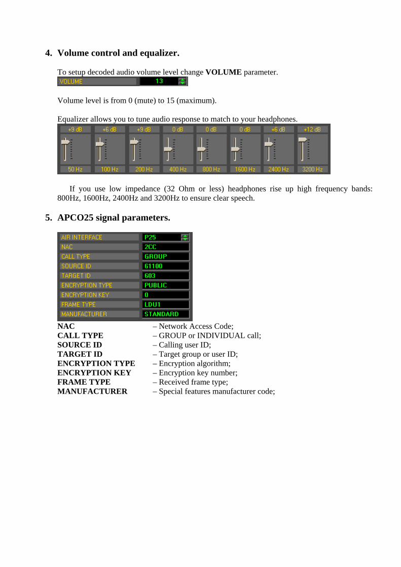
4. Volume control and equalizer.
To setup decoded audio volume level change VOLUME parameter.
Volume level is from 0 (mute) to 15 (maximum). Equalizer allows you to tune audio response to match to your headphones.
If you use low impedance (32 Ohm or less) headphones rise up high frequency bands:
800Hz, 1600Hz, 2400Hz and 3200Hz to ensure clear speech.
5. APCO25 signal parameters.
NAC – Network Access Code; CALL TYPE – GROUP or INDIVIDUAL call; SOURCE ID – Calling user ID; TARGET ID – Target group or user ID; ENCRYPTION TYPE – Encryption algorithm; ENCRYPTION KEY – Encryption key number; FRAME TYPE – Received frame type; MANUFACTURER – Special features manufacturer code;

6. DMR signal parameters.
COLOR CODE – System access code; CALL TYPE – GROUP or INDIVIDUAL call; SOURCE ID – Calling user ID; TARGET ID – Target group or user ID; PRIVACY INDICATOR – Public or encrypted channel; TDMA TIME SLOT – Repeater time slot number; ACCESS TYPE – Repeater input channel state;
7. NXDN4800/NXDN9600 signal parameters.
RAN – Radio Access Number; CALL TYPE – CONFERENCE or INDIVIDUAL call; SOURCE ID – Calling user ID; TARGET ID – Target group or user ID; CIPHER TYPE – Public or scrambled/encrypted channel; KEY ID – Scrambler key id; FRAME TYPE – Received frame type; EMERGENCY – Normal or emergency call;

8. Yaesu C4FM System Fusion signal parameters.
SQUELCH CODE – Code for opening “squelch” (like DCS in analog radio); CALL TYPE – Group or individual call; SOURCE CALLSIGN – Calling radio callsign; TARGET CALLSIGN – Called radio callsign or broadcast “**********”; SQUELCH CODE ENABLED – Calling radio squelch state; DATA TYPE – Type of the used protocol; VOIP PATH – Internet or local call;
9. Conventional digital voice receiving. Enter voice channel or repeater frequency via the keyboard or tune it with mouse wheel.
If received signal power is enough to decode control software will show all decoded signal parameters and pass speech to your headphones.
10. Memory channel storage Press STORE button on the main window.
MEMORY NUMBER – memory channel number; AIR INTERFACE – type of digital standard; FREQUENCY, MHz – frequency; MEMORY SCAN/TRACK LOCK – memory scan or track enable; COMMENTS – channel tag; NAC/CC<x> – channel filter settings; EXCLUDE – channel filter exclude mode; ENABLE – channel filter enable;
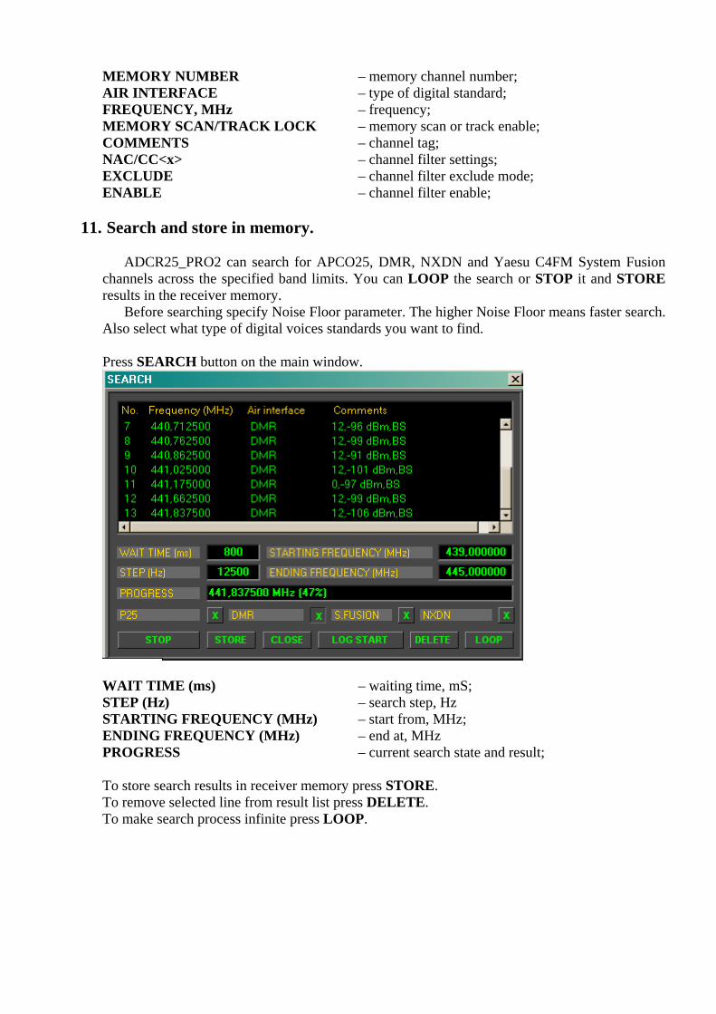
11. Search and store in memory.
ADCR25_PRO2 can search for APCO25, DMR, NXDN and Yaesu C4FM System Fusion
channels across the specified band limits. You can LOOP the search or STOP it and STORE results in the receiver memory.
Before searching specify Noise Floor parameter. The higher Noise Floor means faster search. Also select what type of digital voices standards you want to find.
Press SEARCH button on the main window.
WAIT TIME (ms) – waiting time, mS; STEP (Hz) – search step, Hz STARTING FREQUENCY (MHz) – start from, MHz; ENDING FREQUENCY (MHz) – end at, MHz PROGRESS – current search state and result; To store search results in receiver memory press STORE. To remove selected line from result list press DELETE. To make search process infinite press LOOP.

12. Memory channels scanning.
Press MEM. SCAN.
WAIT TIME (ms) – channel activity wait time, mS; HOLD TIME (ms) – busy channel hold time, mS;
After START pressed receiver successively setting selected memory channels and wait for WAIT TIME on it. Receiver stops on busy channel and plays received speech. After the last voice transmittion is done receiver waits HOLD TIME for any voice activity and then begin to listen next voice channel.
13. Noise Floor setting, S-meter calibration and RF gain set.
Press RF SET.
To calibrate receivers S-meter you need RF signal generator. Tune generator to the receiver frequency and set output level between -80dBm and -110dBm. Changing S-METER OFFSET value achieve equal S-meter reading to your generator. To store new S-meter settings press STORE.
To increase receiver IMD (receiver ability to work in band crowded conditions) you can
change RF GAIN setting. Decrease RF gain to increase receiver IMD. Available values from 0 (maximum sensitivity) to -39dB (maximum IMD).
NOISE FLOOR – this parameter defines noise level above which receiver will search for desired signal type in SEARCH menu.
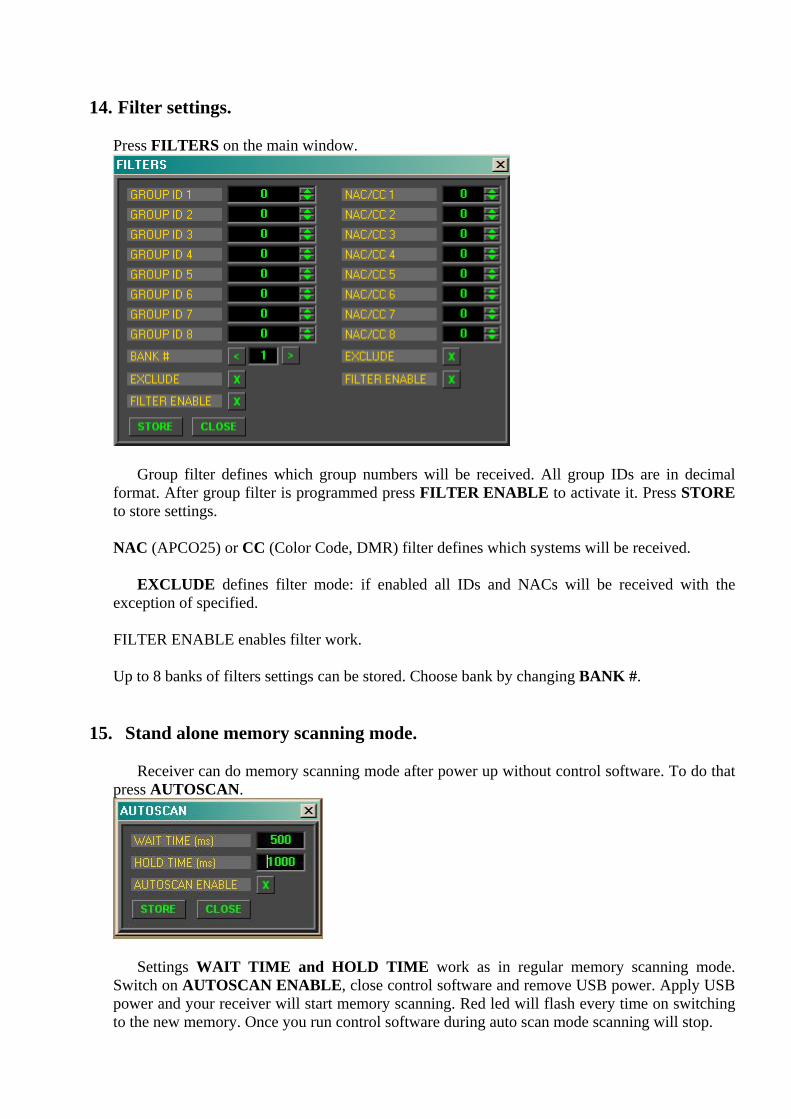
14. Filter settings.
Press FILTERS on the main window.
Group filter defines which group numbers will be received. All group IDs are in decimal format. After group filter is programmed press FILTER ENABLE to activate it. Press STORE to store settings.
NAC (APCO25) or CC (Color Code, DMR) filter defines which systems will be received.
EXCLUDE defines filter mode: if enabled all IDs and NACs will be received with the
exception of specified.
FILTER ENABLE enables filter work.
Up to 8 banks of filters settings can be stored. Choose bank by changing BANK #.
15. Stand alone memory scanning mode.
Receiver can do memory scanning mode after power up without control software. To do that
press AUTOSCAN.
Settings WAIT TIME and HOLD TIME work as in regular memory scanning mode. Switch on AUTOSCAN ENABLE, close control software and remove USB power. Apply USB power and your receiver will start memory scanning. Red led will flash every time on switching to the new memory. Once you run control software during auto scan mode scanning will stop.
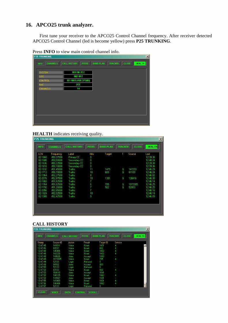
16. APCO25 trunk analyzer.
First tune your receiver to the APCO25 Control Channel frequency. After receiver detected APCO25 Control Channel (led is become yellow) press P25 TRUNKING.
Press INFO to view main control channel info.
HEALTH indicates receiving quality.
CALL HISTORY
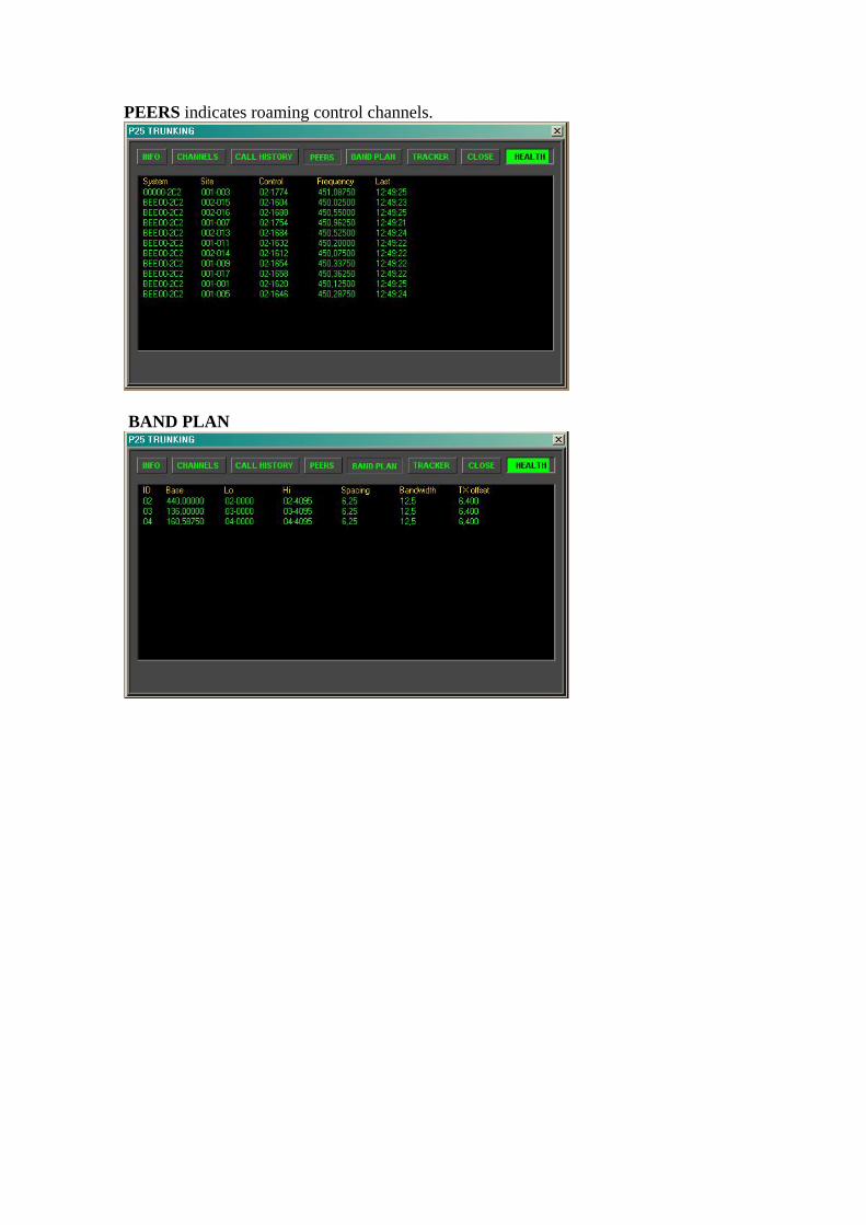
PEERS indicates roaming control channels.
BAND PLAN
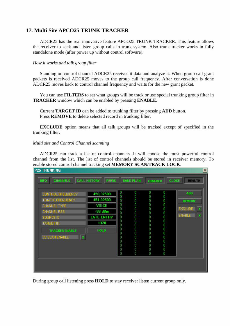
17. Multi Site APCO25 TRUNK TRACKER
ADCR25 has the real innovative feature APCO25 TRUNK TRACKER. This feature allows
the receiver to seek and listen group calls in trunk system. Also trunk tracker works in fully standalone mode (after power up without control software).
How it works and talk group filter
Standing on control channel ADCR25 receives it data and analyze it. When group call grant
packets is received ADCR25 moves to the group call frequency. After conversation is done ADCR25 moves back to control channel frequency and waits for the new grant packet.
You can use FILTERS to set what groups will be track or use special trunking group filter in
TRACKER window which can be enabled by pressing ENABLE.
Current TARGET ID can be added to trunking filter by pressing ADD button. Press REMOVE to delete selected record in trunking filter. EXCLUDE option means that all talk groups will be tracked except of specified in the
trunking filter.
Multi site and Control Channel scanning
ADCR25 can track a list of control channels. It will choose the most powerful control channel from the list. The list of control channels should be stored in receiver memory. To enable stored control channel tracking set MEMORY SCAN/TRACK LOCK.
During group call listening press HOLD to stay receiver listen current group only.

CC SCAN ENABLE – Receiver will scan stored in memory control channels with WAIT time and HOLD time settings from AUTOSCAN menu settings. Run CC SCAN ENABLE before TRACKER ENABLE.
18. ADCR25_PRO2 & UniTrunker (PRO96COM).
ADCR25_PRO2 emulates GRE PSR-600 control protocol and can communicate with
UniTrunker or Pro96COM software.
To download UniTrunker use this shortcut http://www.unitrunker.com/
First determine ADCR25_PRO2 com port number. For that run ADCR25_PRO2 control software and get com port number from the bottom of the main window:
Then close control software and run UniTrunker software
To create new receiver press “+” in the main window. To remove selected receiver press “-” in the main window.
Each receiver connected with UniTrunker can be Signal (to receive control channel data) or
Voice (to receive voice data and playback the audio). Define that in Role field. In the field Type select Inline for both of ADCR25_PRO2 receivers.
ADCR25_PRO2 com port settings for UniTrunker: Baud Rate: 115200 Data bits: 8 Stop bits: 1 Parity: None ADCR25 is in Signal role:
ADCR25 is in Voice role:

Before running the receivers set signal receiver to the control channel frequency:
For that type control channel frequency in Park field and press Skip button.
To run the receiver press Start button.
After that ADCR25_PRO2 automatically recognize control channel and start data transmitting to its com port.
To allow trunk tracking run second ADCR25_PRO2 which is in Voice role and set in the
Options Listen Enabled setting.