Embed Size (px)
Citation preview

----- -- ---- ---- --------- ===:::;::" - --= - ':' = Application Program
1440/1460 Administrative Terminal System
(1440-CX-07X and 1460-CX-OBX)
Programmer's Manual
This system consists of control and functional programs that permit many different textprocessing activities to be carried on simultaneously through different terminals. This reference manual contains a general description of the programs. It also contains information required by a programmer who wishes to add peripheral programs or new functions ·to the system.
H20-0228-0

PREFACE
The material in this manual relates to Version 2 of the IBM 1440/1460 Administrative Terminal System program. It obsoletes and replaces the Preliminary Edition issued with Version 1 of the program.
This publication was prepared for production using the IBM 1440/1460 Administrative Terminal System. Page impressions for photo-offset printing were obtained from a typewriter terminal and reduced 15 percent.
Copies of this and other IBM publications can be obtained through IBM Branch Offices. Address comments concernin9 the contents of this publication to IBM, Technical Publications Department, 112 East Post Road, White Plains, New York 10601.

£ONTENTS.
INTRODUCTION •••••••••••••••••••••••••••••••••••••••••••••••• 1
GENERAL DESCRIP'rION ••••••••••••••••••••••••••••••••••••••••• 2
PROGRAMMING TECHNIQUES •••••••••••••••••••••••••••••••••••••• 5 Dynamic Storage Allocation •••••••••••••••••••••••••••••••••• 5
Dynamic Core Allocation •••••••••••••••••••••••••••••••••• 5 Dynamic Disk Allocation •••••••••••••••••••••••••••••••••• 7 Dynamic Allocation in ATS •••••••••••••••••••••••••••••••• 8
Multiprogramming •••••••••••••••••••••••••••••••••••••••••••• 8 List Processing ••••••••••••••••••••••••••••••••••••••••••••• 9
THE SYSTEM •••••••••••••••••••••••••••••••••••••••••••••••••• 13 The Multiplexor ••••••••••••••••••••••••••••••••••••••••••••• 13
Status Characters •••••••••••••••••••••••••••••••••••••••• 13 Running Address •••••••••••••••••••••••••••••••••••••••••• 14 Interrupt •••••••••••••••••••••••••••••••••••••••••••••••• 15 Early Warning •••••••••••••••••••••••••••••••••••••••••••• 15 The Scan................................................. 17
The Terluinals ••••••••••••••••••••••••••••••••••••••••••••••• 17 Transmission Code •••••••••••••••••••••••••••••••••••••••• 17 Line Control ••••••••••••••••••••••••••••••••••••••••••••• 17 Output Timing Considerations ••••••••••••••••• 0........... 17
The Disk Files •••••••••••••••••••••••••••••••••••••••••••••• 18
STORAGE ALLOCATION •••••••••••••••••••••••••••••••••••••••••• 21 Disk Storage Allocation ••••••••••••••••••••••••••••••••••••• 21 Core Storage Allocation ••••••••••••••••••••••••••••••••••••• 23
SYSTEM TABLES ••••••••••••••••••••••••••••••••••••••••••••••• 27 System Status Table ••••••••••••••••••••••••••••••••••••••••• 27 Program Status Table •••••••••••••••••••••••••••••••••••••••• 29 Character Status Table •••••••••••••••••••••••••••••••••••••• 30 ,1\rm Table ••••••••••••••••••••••• "........................... 31 'rerminal Status Table ••••••••••••••••••••••••••••••••••••••• 32
Inactive Status •••••••••••••• "........................... 32 Active Status •••••••••••••••• CI........................... 32
Multiplexor Status Table •••••••• 0........................... 33 List Entries .0 .................. 0........................... 34
Availability Entry ••••••••••• 0........................... 34 NJB Entry .0 ....•............. 0........................... 35 ARM Entry • 0 •••••••••••••••••• 0 • • • • • • • • • • • • • • • • • • • • • • • • • • • 35 WPA Entry • II •••••••••••••••••• II • • • • • • • • • • • • • • • • • • • • • • • • • • • 36
TEXT S'l'REAM PROCESSING ............................... 0 • • • .. • • • 37 Working Storage ••••••••••••••••••••••••••••••••••• ~......... 37 Core Blocks •• '. • • • • • • • • • • • • • • • • • • • • • • • • • • • • • • • • • • • • • • • • • • • • • • 38
Block in Free storage •••••••••••••••••••••••••••••••••••• 39 Block in Receive Status •••••••••••••••••••••••••••••••••• 39 Block in Transmit Status ••••••••••••••••••••••••••••••••• 41
ATS Text-Handling Conventions ••••••••••••••••••••••••••••••• 43 Receive status ••••••••••••••••••••••••••••••••••••••••••• 43 Transmit St,atus •••••••••••••••••••••••••••••••••••••••••• 43
First Block Area •••••••••••••••••••••••••••••••••••••••••••• 44 Permanent Storage ••••••••••••••••••••••••••••••••••••••••••• 46
Permanent Storage Index •••••••••••••••••••••••••••••••••• 48 Half-Tracks •••••••••••••••••••••••••••••••••••••••••••••• 49 Half-Track Allocation and Deletion ••••••••••••••••••••••• 51
Permanent Storage Tape •••••••••••••••••••••••••••••••••••••• 51
SYS TEM PROGRAMS •••••••••••••••••••••••••••• ~ •••••••••••••••• Items in Lower Core Storage •••••••••••••••• ~ •••••••••••••••• System Messages •••••••••••••••••••••••••••• ' ••••••••••••••••• The Scheduler •••••••••••••••••••••••••••••• t ••••••••••••••••
Input/Output Control (IOCNX) ••••••••••••••• ~ •••••••••••••••• Chain (CHAIX) ••••••••••••••••••••••••••••••••••••••••••••••• Next Disk Block (NDBKX) •••••••••••••••••••• ~ •••••••••••••••• Purge Disk Block (PDBKX) ••••••••••••••••••• ~ •••••••••••••••• Next Core Block (NCBKX) •••••••••••••••••••• ~ •••••••••••••••• Head of Free Storage (HDFSX) ••••••••••••••• ~ •••••••••••••••• Foot of Free Storage (FTFSX) ••••••••••••••• ~ •••••••••••••••• Set New Job (SNJBX) ••••••••••••••••••••••••••••••••••••••••• Same Uni t (SMUNX) •••••••••••••••••••••••••• It ••••••••••••••••
New Unit (NWUNX) ............................................ . Retrieve (RTRVX) ................................ (\ ••••••••••••
MISCELLANEOUS PROGRAMMING NOTES ••••••••••••••••••••••••••••• Source Program Preparations •••••••••••••••••••••••••••••••••
Programming Language ••••••••••••••••••••••••••••••••••••• Source Program Decks ••••••••••••••••••••••••••••••••••••• Job Card ................................................. . Literal Origin (LTORG) Statements •••••••••••••••••••••••• Origin (ORG) Statements •••••••••••••••••••••••••••••••••• COMPOOL (Communication Pool) •••••••••••••••••••••••••••••
Disk Load Program (DSKLD) ••••••••••••••••••••••••••••••••••• Writing Peripheral Programs ••••••••••••••••••••••••••••••••• Writing Application Programs ••••••••••••••••••••••••••••••••
Coding Practices ••••••••••••••••••••••••••••••••••••••••• Locating the Attention Line •••••••••••••••••••••••••••••• Interpreting the Attention Line •••••••••••••••••••••••••• Numeric Character Translation •••••••••••••••••••••••••••• Shift Characters ••••••••••••••••••••••••••••••••••••••••• Overlays ••••••••••••••••••••••••••••••••••••••••••••••••• Special Messages ••••••••••••••••••••••••••••••••••••••••• Output Text Streams •••••••••••••••••••••••••••••••••••••• Priority Interrupt •••••••••••••••••••••••••••••••••••••••
SYSTEM OUTPUT FORMATS ....................................... Permanent Storage Tape •••••••••••••••••••••••••••••••••••••• Card Image Tape ••••••••••••••••••••••••••••••••••••••••••••• Print with Line Numbers Tape •••••••••••••••••••••••••••••••• Upper- and Lowercase Chain Print Tape ••••••••••••••••••••••• Storage Report Tape •••••••••••••••••••••••••••••••••••••••••
APPENDIX A: Sample coding for a SRANB subroutine · ........... APPENDIX B: Sample coding for a RTBLK subroutine · ........... APPENDIX C: Sample coding for a SSPRT subroutine • ••••••••••• APPENDIX D: Sample coding for a routine to read overlays .... APPENDIX E: Sample table for communication between overlays APPENDIX F: Sample coding for a subroutine to chain
Working Storage to another block •••••••••••••••
53 53 53 54 56 57 57 57 58 58 58 59 59 59 59
61 61 61 61 6'2 62 62 63 63 65 67 67 67 72 72 74 74 75 77 77
78 78 79 79 79 82
83 84 85 86 87
88

.... IN_T;.;.,oR-.O ... D_U ... C!.!2~
It is intended that this manual serve as a reference manual for programmers concerned with the Administra'tive Terminal System (ATS). The manual includes a description of the system, beginning with a general discussion of 'techniques involved and developing into a detailed treatment of -the programs and indicators. Material is presented to pE~rmit each reader to investigate the subject as his own interests and requirements demand.
It is assumed that the reader of this manual is familiar with the following IBM publications:
IBM 1440/1460 Administrative Termina~ System, Terminal Operator's Manual'(H'-O-Ol8!r
IBM l14~/t460 Administrative Termina~ System, Console Operator's Manu a H~227)
It is also assumed tha't the reader is familiar with the IBM Systems Reference Library publications describing the various components of IBM 1440 and 1460 Data Processing Systems that may be used in connection with the IBM 1440/1460 Administrative Terminal System. The reader should, in addition, be generally familiar with the IBM Systems Reference Library publications describing the IBM 1401/1440/1460 Autocoder (On Disk) progranuning system.
-1-

GENERAL DESCRIPTION
The IBM 1440/1460 ATS program is concerned with allowing up to 40 remote terminals simultaneous access to a data processing systeim. A wide variety of program-controlled operations are available to each terminal, operating independently.
Keystrokes entered at the terminals are collected by the system as strings of characters called text streams. These text streams are accumulated in core storage in 100-character, dynamically allocated data areas called core blocks. Twenty-five characters of the data area are necessary for control, 75 for text. When 75 characters have accumulated in a core block, the text is written to IBM 1311 Disk Storage using a chaining technique. Thus, the text stream input from each terminal is in the form of a chain of blocks, each link containing up to 75 characters of text. This chain is called Working storage. Working Storage for each terminal is both on the disk and in core storage.
Hardware and formatting requirements make the Working Storage (input) text stream unsuitable for transmission back to the terminal. Whenever a printout is requested from the terminal, a ~ of the original text stream is program-generated. This speci~utput text stream is the logical reverse order from the input text stream. Text streams are illustrated in Figure 1.
Input Stream
Output Stream
Beginning
of Document
End of
Document
Blocks on 0 I sk
01_~-
D1_~-Figure 1. Input and output text streams
-
Blocks In Core
End of
Document
Beginning of
Document
~
Terminal
4 "
~
The input text stream is kept intact until deliberately destroyed as a result of a program request from the terminal operator. In contrast, the output text stream is destroyed as it is used.
Documents in Working Storage may be copied into another area of the disk called Permanent Storage. The terminal operator assigns t~he document a number. This number refers to a specific locat.ion in an index, which, in turn, contains the disk address of the beginning of the document. Permanent Storage is chained in a manner analogous to Working Storage, in blocks of 900 characters.
When accumulating text from the terminals, the system does not ordinarily examine the text stream for content. Thus, to distinguish a pr09ram request from ordinary text, the te~inal is provided with
-2-
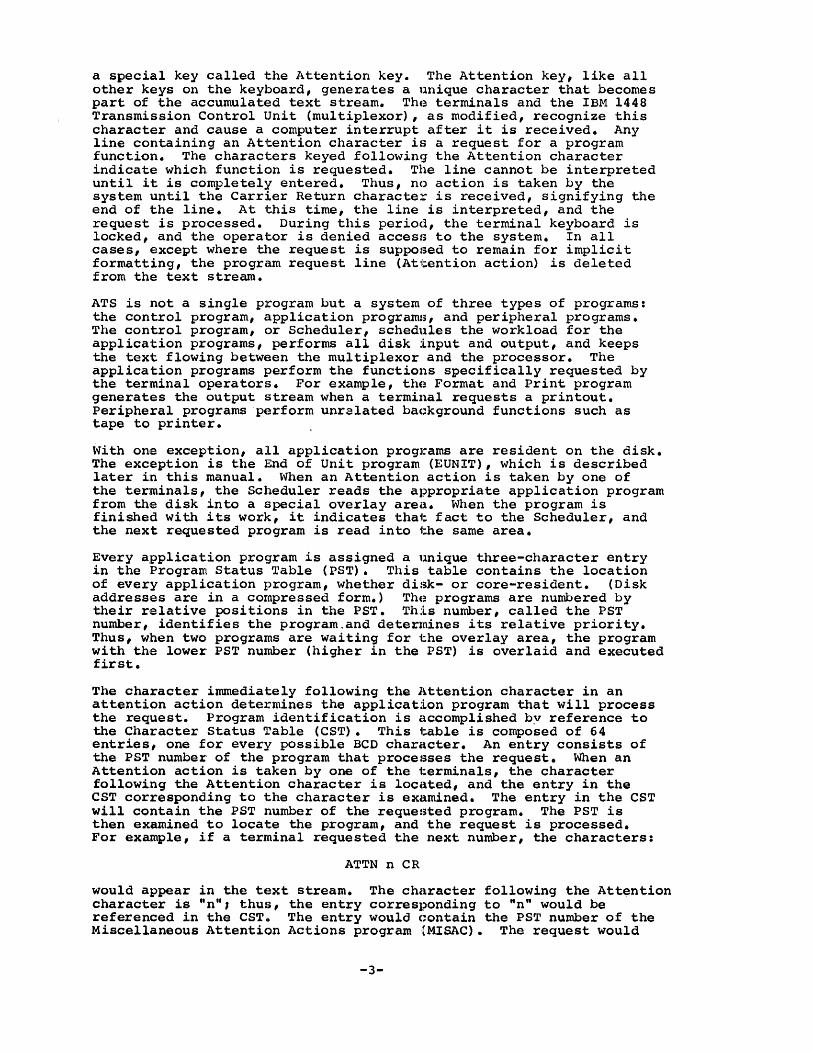
a special key called the Attention key. The Attention key, like all other keys on the keyboard, generates a unique character that becomes part of the accumulated text stream. The terminals and the IBM 1448 Transmission Control Unit (multiplexor), as modified, recognize this character and cause a computer interrupt after it is received. Any line containing an Attention character is a request for a program function. The characters keyed following the Attention character indicate which functic)n is requested. The line cannot be interpreted until it is completely entered. Thus, no action is taken by the system until the Carrier Return character is received, signifying the end of the line. At this time, the line is interpreted, and the request is processed. During this period, the terminal keyboard is locked, and the operator is denied access to the system. In all cases, except where the request is supposed to remain for implicit formatting, the program request line (Attention action) is deleted from the text stream.
ATS is not a single program but a system of three types of programs: the control program, application programs, and peripheral programs. The control program, or Scheduler, schedules the workload for the application programs, performs all disk input and output, and keeps the text flowing betwE~en the multiplexor and the processor. The application programs perform the functions specifically requested by the terminal operators. For example, the Format and Print program generates the output stream when a terminal requests a printout. Peripheral programs perform unralated background functions such as tape to printer.
with one exception, all application programs are resident on the disk. The exc.eption is the End of Unit program (EUNIT), which is described later in this manual. When an Attention action is taken by one of the terminals, the Scheduler reads the appropriate application program from the disk into a special overlay area. When the program is finished with its work, it indicates that fact to the Scheduler, and the next requested program is read into the same area.
Every application program is assigned a unique three-character entry in the Program Status Table (PST). This table contains the location of every application program, whether disk- or core-resident. (Disk addresses are in a compressed form.) ThE;! programs are numbered by their r,elative positions in the PST. This number, called the PST number, identifies the program.and deterxnines its relative priority. Thus, when two programs are waiting for the overlay area, the program with the lower PST number (higher in the PST) is overlaid and executed first.
The character immediately following the Attention character in an attention action determines the application program that will process the request. Program identification is accomplished by reference to the Cha.racter Status Table (CST). This table is composed of 64 entries, one for every possible BCD character. An entry consists of the PST numbex' of the program that processes the request. When an Attention action is taken by o~ of the terminals, the character following the Attention character is located, and the entry in the CST corresponding to t:.he character is examined. The entry in the CST will contain the PST number of the requested program. The PST is then examined to locate the program, and the request is processed. For example, if a terminal requested the next number, the characters:
ATTN n CR
would appear in the text stream. The character following the Att~ntion character is "n", thus, the entry corresponding to "n" would be referenced in the CSTo The entry would contain the PST number of the Miscellaneous Attention Actions program (MISAC). The request would
-3-
then be sorted into the line or queue of programs waiting for the overlay area according to the PST number. t'Jhen the queue was processed to the point of the entry, the position indicated by the PST number would be examined in the PST, and the physical location of the program determined. The program would then be read from the disk and executed.
The CST and PST entries are the communication links to the application programs. When a new application program is added, appropriate entries in these two tables are the only system modifications that are required.
-4-

PROGRAMll1ING TECHNIQUES.
This section contains a general description of some of the programming techniques used in ATS. It must be thoroughly understood before the detailed operation of the system is studied. The ways that these techniques are used in various parts of the ATS program will be covered in the detailed descriptions of these parts in later sections of this manual.
DYNAMIC STORAGE ALLOCATION
Dynamic Core Allocatio,!!
Information is usually stored by means of several contiguous words or blocks having addresses and block lengths -t.hat are known to the progra~ner. Access to a block is then controlled by the known address modified by an index register. An example is shown in Figure 2.
Location 1440 1420 1400 1380 1360 1340 1320 1300
20 Positions
Figure 2. Fixed core blocks
In a fixed table, block entries are numbered from zero to N-I, where N is the total number of blocks. To reference any block, the block number times the length of the block is loaded into an index register. Reference is then made by addressing the desired field in block zero plus the contents of the index. Thus, in the above example, to reference the sixth character in the fifth block, 4 (the block number) times 20 (the length of the field) is loaded into an index register. The number 1305 (the character position in block zero) added to the index will yield character position 1385, or the sixth character in the fifth block.
This organization lends itself well to tables of fixed length that change infrequently. However, when dealing with data of unknown length that must be constantly manipulated, a more flexible technique is desired. Dynamic storage allocation is such a technique.
If a portion of each register or block is allocated to control information, namely, the address of the block following, the scheme would appear as shown in Figure 3.
-5-

Location Pointer Location Pointer
300 400 700 I 800 I
400 500 800 I 900 1
500 600 900 11000 I
600 I 700 I 1000 IBlank I Figure 3, Core blocks chained together with pointers
The address in the block is called a pointer because it "points" to the next register. A pointer that is blank denotes the end of the table. This technique is also called chaining.
It is immediately apparent that these registers may be randomly located tl.lroughout memory. Thus, contiguous registers are not necessary. Also, sorting becomes merely the manipulation of addresses, rather than the movement of entire blocks.
In most systems using dynamic storage, the concept of "free storage" is used. Free storage is a chain of available blocks which are unused at the moment and which may be requested. The technique is de\reloped so that when a program needs an additional block, it "takes" one from free storage, adds it to its chain of blocks, and reunites the free storage chain around the missing element. Actually, "taking" a block from free storage entails only the changing of the pointers. The pointer in the last block of the chain associated with the program is changed to point to the block to be extracted from free storage, while the chaining of the free storage blocks is altered to exclude the "missing" block. An example is shown in Figure 4.
Before "Taking" Block At 1000
Program·s Chain Free Storage Chain
Location Pointer Location Pointer
300 1400 I 700 L..I _80_0--'-___ _
400 [500 I 800 L-I _90_0--'-___ _
500 1600 1 900 11000 1
600 IBlank I 1000 IBlank I After Program "Takes" Block At 1000
Program·s Chain Free Storage Chain
Location Pointer Location Poi nter
300 1400 700 '-1 -80-0~----
400 1500 800 .... 1 _90_0--'-___ _
500 1600 900 1 Blank I
600 11000 I
1000 IBlank 1
Figure 4,Core blocks in two chains
-6-

Conversely, when a program has finished with a block, it is "purged" or "returned" to free storage. Again, the purging of a block entails merely the rechaining of addresses.
Although the examples given above are contiguous, the random nature of this method should be obvious. Also, the program may chain in a block at any point in its Working Storage, not necessarily at the end.
Knowing the address of the first block of a chain enables the program, by following the chaining addresses, to find any particular element in the chain. This search may be facilitated if, in addition to a chaining address pointing to the next block, another address is used to point to the preceding block. Such a scheme is illustrated in Figure 5.
Backward Forward Location Pointer Poi nter
Head of 400 ~nk 500 Chain
500 000 600
600 L100 700
700 COOo 800
Foot of 800 [l00 Blank Chain
Figure 5. Core blocks with two-way chaining
In this scheme, the first address points "backward" in the chain, while the second address points "forward". With this additional address, it is possible, given any block in the chain, to search in either direction. Note that when the end of the chain is reached going either forward or backward, the chaining address is blank.
Using this met,hod of t:wo-way chaining, it is desirable to know the locations of both the beginning and the end of the chain, which are called the head and the foot of the chain, respectively. Pointers to these locations are stored in fields with fixed locations termed the "he,ad pointer" and the "foot pointer".
Dynamic Disk Allocatio21
Although the technique described above refers to allocation in core storage, an analogous procedure makes very effective use of random (disk) storage. When dynamically allocated disk storage is used, the chainin'9 addresses become sector addresses. Here again, two-way chaininlg is desirable to increase the efficiency of a search.
Dynamically allocated disk storage is clearly a superior technique when random-length records must be processed. The storage space used by the lchaining addresses is trivial when compared to the large
-7-
portions of the disk that are unused in a contiguous technique. Also, because each cylinder is fully utilized before going to the ne:x:t and because no reshuffling of records is necessary, the number of disk accesses is greatly reduced, especially the disk "seek". Thus, system efficiency is maximized.
~vi th record elements that exceed one sector in length, the dynamic technique can be implemented by chaining groups of sectors. Thus, with long elements, the use of chained groups of sectors (where the groups of sectors are contiguous) results in optimum use of the disk.
A concept analogous to "free storage" is used with dynamic disk allocation. Instead of a chain of available blocks (sectors), a pool of available sector addresses is kept. These addresses are allocated from one end of the disk (highest addresses, for example) and as more sectors are required, they are added to the pool, moving sequentially across the disk. For example, the pool might begin by including all of the addresses in the highest cylinder of the disk. As these addresses are used up, the addresses in the next cylinder down would be requisitioned.
When a program has finished with a sector, that sector is "purged" or made available for reuse. Again, because a pool of disk addresses, not a chain of free storage, is used, a disk sector is purged by returning the address to the pool. No additional access to the disk is required.
D~namic Allocation in ATS
Several variations of the above-described allocation techniques are used in the ATS. The one-way chaining technique is used to link the elements in the list area, which is described in the section "List Processing". Two-way chaining is used in several variations in the IOO-character core blocks used to receive text before writing it to the disk (described in the section "Core Dlocks"). In both the list area and the core blocks, the concept of free storage is used.
Disk storage is allocated by chained sector~ for the text as it is received and manipulated by the program. A pool of sector addresses is kept as explained above.
In addition to the chained sector storage, called Working Storage, text to be stored permanently is written in chained groups of ten sectors. A similar, but slightly modified, technique of the address pool is used here.
MULTIPROGRAMMING
Multiprogramming is the apparent simultaneous operation of two or more programs. Multiprogramming is not to be confused with multiprocessing, which is the execution of two or "more programs that are independently and simultaneously executing instructions. An example of multiprocessing is the simultaneous operation of the Central Processing Unit (CPU) and a data channel in the IBM System/360. Multiprogramming is the apsarent simultaneous operation of" two or more programs in a single PU.
-8-
\fuen time is not a prime factor, a program can afford to wait for input/~:>utput operations to be completed.. However, in a real-time situation in which the program must be able to react to external conditions within a specified amount of time, processing time must be conserved.
The "seek" instruction in direct access storage is a very timeconsuming input/output operation. This is so because it involves the mechanical motion of the access arm. Because seek instruction may be given, and processing may occur at the same time that the arm is in motion, it does not seriously delay the program. Moreover, an inquiry may be made to see if the arm has reached its destination. If it has not, more processing may be done.
Multiprogramming is a technique used to take advantage of the processing time while the arm is seeking. In its implementation, two or more programs are in core at the same time, each with its separate function to perform. When traffic with the disk is required by one of the programs, it branches to an executive routine conveying the address of the sector(s) that it needs. The executive routine proceeds to give tile disk seek and then branches to another program in core. The second prograJn works until it has completed its task or until such time as it neE~ds access to the disk file. If disk access is required, the second progr~m branches to the executive routine with an appropriate callin~T sequence giving the address of the sector(s) required. This second request is placed in a queue behind the first request.
The logic in the Scheduler is that waiting input/output operations that have been completed are processed before any new programs are allowed to operate. Thus, in the above example, after the second program requested a disk access, the Scheduler would first check to see if the input/output of the first program was completed. If so, it woul.d branch to the first program. If not, it could branch to a third programtl The actual disk read or write operation is performed wheneve.r control is given to the Scheduler by an interrupt (see the section "The Multiplexor") •
In a multiprogrammed system, from the individual program viewpoint, input/output is instantaneous. It requests I/O and, by the time it execute:s the next ins'truction, the opera'tion is completed. Thus, several programs are all operating, from their individual viewpoints, at the same time.
LIST PR.OCESSING
In a multiprogrammed system with a conceivably long queue of waiting input/output requests, some manageable technique must be devised to keep track of the I/O demands. Moreover, if the system is running in real time, it must react to external conditions arising on a random basis -- conceivably, several arising simultaneously. Thus, demands on the system must also be arranged in a queue.
One solution to these problems is the concept of a list. A list is a group of 'registers, containing control information, placed in a string or queue so thclt they may be processed sequentially.
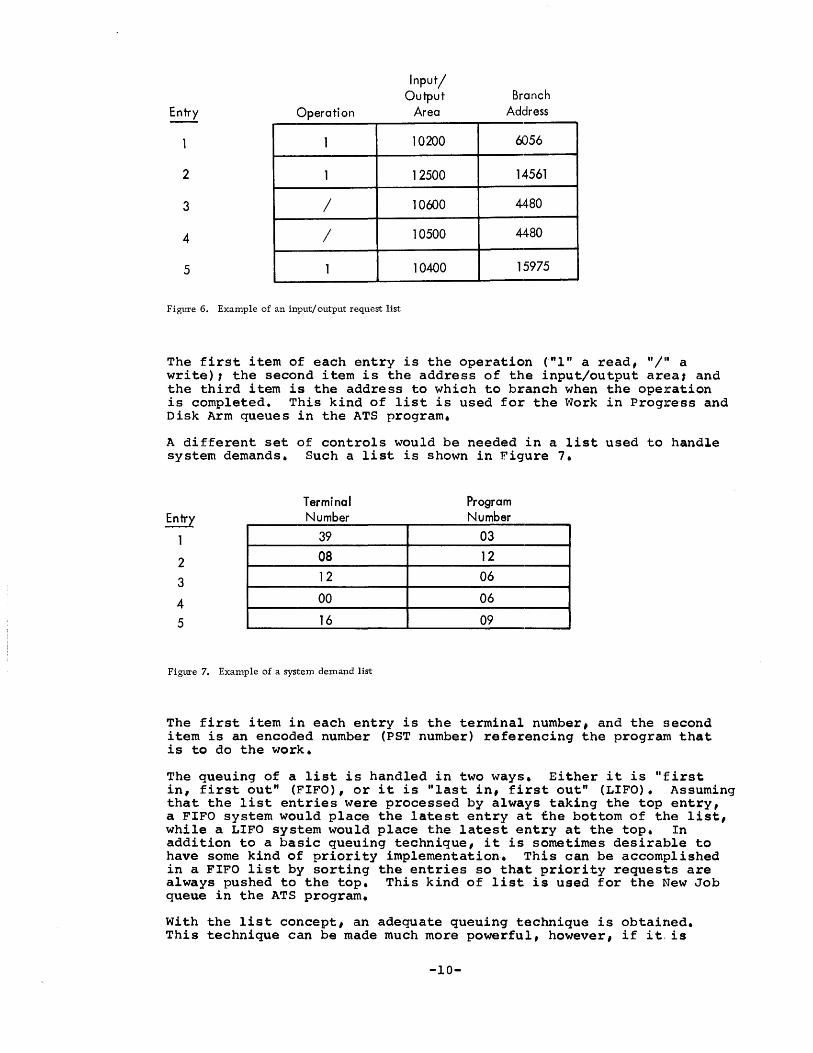
The control information in a list queuing input/output requests, for example, might include the type of operation (that is, read or write) , the area in which the operation is to be made, and the address to branch ,to when the operation is complete.. Such a list is shown in Figure 6.
-9-
Operation
1
2 1
3 /
4 /
5 1
Figure 6. Example of an input/output request list
Input/ Output
Area
10200
12500
10{JJ0
10500
10400
Branch Address
(JJ56
14561
4480
4480
15975
The first item of each entry is the operation t"l" a read, "I" a write), the second item is the address of the input/output ar~:!a: and the third item is the address to which to branch when the operation is completed. This kind of list is used for the t'lork in Progress and Disk Arm queues in the ATS program.
A different set of controls would be needed in a list used to handle system demands. Such a list is shown in Figure 7.
Entry
1
2
3
4
5
Terminal Number
39 08 12
00
16
Figure 7. Example of a system demand list
Program Number
03 12 06
06
09
The first item in each entry is the terminal number, and the second item is an encoded number (PST number) referencing the program that is to do the work.
The queuing of a list is handled in two ways. Either it is "first in, first out" (FIFO), or it is "last in, first out" (LIFO). Assuming that the list entries were processed by always taking the top entry, a FIFO system would place the latest entry at the bottom of the list, while a LIFO system would place the latest entry at the top. In addition to a basic queuing technique, it is sometimes desirable to have some kind of priority implementation. This can be accomplished in a FIFO list by sorting the entries so that priority requests are always pushed to the top. This kind of list is used for the New Job queue in the ATS program.
with the list concept, an adequate queuing technique is obtained. This technique can be made much more powerful, however, if it. is
-10-

implemented with the dynamic storage concept. Thus, the list entries can be located at random, connected only by chaining addresses. Figure 8 contains an example of a dynamic list.
Entry Chaining Location r I I Address
Entry" Chaining Location I I I Address
300~ 330 GI 16 1250 320
340 G I 217 375 310
350 ~ I 876 I 195 340
Figure 8. Example of a dynamic list:
The last item in each entry is a chaining address (pointer). This particular list begins in location 300 and ends in location 310. Note that the blank chaining address denotes the end of the list.
The immediate advantage of a dynamic list is that the addition of new entries and the task of priority sorting become simply the manipulation of chaining addresses, eliminating the necessity of complete record moves. Also, the program required to manipulate a dynamic list is extremely short.
In a real-time system, there are a number of operations that must be queued. For example, there might be five disk drives attached to the system. If so, it is apparent that I/O requests can be more efficiently handled if they are queued up for the respective arms where access is required. In this case, five queues, or one for each arm, would be desirable. In addition, a separate queue of completed I/O requests would be needed. As explained previously, a queue is necessary to process outside demands on the system. The handling of seven separate lists is considerably alleviated if the free storaqe concept is considered. If a chain of Available list entries is used, there is no reas,on why all seven lists cannot be in the same "list area". To implement this condition, eiqht "pointer reqisters" must be allocated in fixed positions. Each of these pointers points to the top entry in its own dynamic list chain. The Available Pointer, for example, points to the tcp entry in the free storage list. Each of the five Arm Pointers points t() the top entries in its respective list. The Work in Progress Pointer points to the tC)P entry in the completed I/O list and the New Job Pointer points to the top entry in the list of new demands on the system.
In the implementation described above, as in most dynamic storaqe allocation schemes, a pointer that" is blClnk denotes the end of a chain. When a new list entry is needed, say for the New Job list, it is u:nchained from the Available list and rechained in its proper priority order in the New Job list. Thus, the addition and priority sort of a list entry can be done in one operation. When the entry has served its purpose, it is purged, or returned, to the Available list.
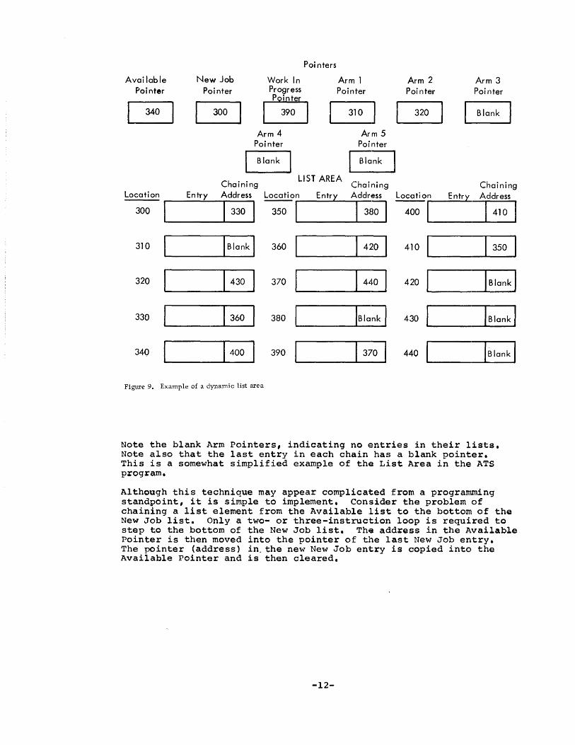
An example of a dynamic list area at anyone instant is shown in Figure 9.
-11-
Poi nters
Available New Job Work In Arm 1 Arm 2 Arm 3 Pointer Poi nter Progress Pointer Poi nter Poi nter
[;J 340 0 390 G 320 L Blank
Arm 4 Arm 5 Pointer Pointer
Blank Blank
Chaining LIST AREA
Chaining Chaining Location Entry Address Location Entry Address Locati on Entry Address
1330
1
---1
380 I 1
410 1
300 350 400
310 IBlank 1 360 420 410 B 320 430 370 440 420 IBlank I 330 360 380 IBlank 1 430 IBlank 1
340 1
400 390 370 440 CB Figure 9. Example of a dynamic list area
Note the blank Arm Pointers, indicating no entries in their lists. Note also that the last entry in each chain has a blank pointer. This is a somewhat simplified example of the List Area in the: ATS program.
Although this technique may appear complicated from a prograrrmdng standpoint, it is simple to implement. Consider the problem of chaining a list element from the Available list to the bottom of the New Job list. Only a two- or three-instruction loop is required to step ~o the bottom of the New Job list. The address in the Available Pointer is then moved into the pointer of the last New Job entry. The pointer (address) in. the new New Job entry is copied into the Available Pointer and is then cleared.
-12-
THE SY2!E:!
This section discusses some programming aspects of the systems that use the ATS program. Except where the operation of specially modified equipment is described, the IBM Systems Reference Library publications describing the equipment should also be consulted.
THE MULTIPLEXOR
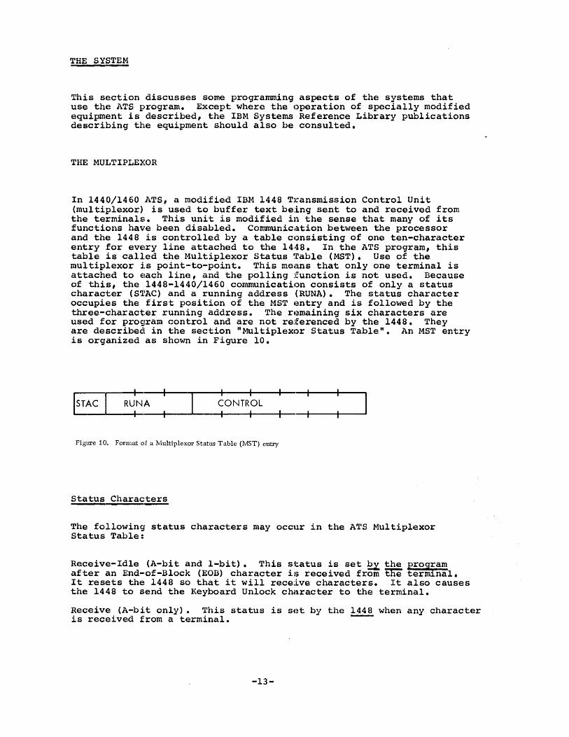
In 1440/1460 ATS, a modified IBM 1448 Transmission Control Unit (multiplexor) is used to buffer text being sent to and received from the terminals. This unit is modified in the sense that many of its functions have been disabled. Communication between the processor and the 1448 is controlled by a table consisting of one ten-character entry for every line attached to the 1448. In the ATS program, this table is called the ~1ultiplexor Status Table (MST). Use of the mul tiplexor i.s point-·to-point. This means that only one terminal is attached to each line, and the polling function is not used. Because of this, the 1448-1440/1460 communication consists of only a status character (S'l'AC) and a running address (RUNA). The status character occupies the first position of the MST entry and is followed by the three-character running address. The remaining six characters are used for program control and are not referenced by the 1448. They are described in the section "Multiplexor Status Table". An MST entry is organized as ShO~l in Figure 10.
ISTAC : : : Figure 10. Format of a Multiplexor Status Table (MST) entry
Status Characters
The following status characters may occur in the ATS Multiplexor Status Table:
Receive-Idle (A-bit and l-bit). This status is set ~ the program after an End-of-Block (EOB) character is received from the terminal. It resets the 1448 so that it will receive characters. It also causes the 1448 to send the Keyboard Unlock character to the terminal.
Receive (A-bit only).. This status is set by the!.!!! when any character is received from a terminal.
-13-
Receive End of Block (A-bit and wordmark). A special End-of-Block (EOB) character is transmitted to the 1448 by the terminal immedi,ately following the Attention or Carrier Return characters. The EOB character never reaches core, however. Instead, the wordmark bit is set in the status character for that line ~ ~ 1448.
Receive End of Storage (A-bit and 8-bit). This status is set ~ the 1448 whenever it attempts to store characters over a groupmarklwordmark. -Receive Check (A-bit and 2-bit). If an invalid character is received, or if the two-character buffer storage overflows, this status is set ~ ~ ll!!. Transmit (B-bit <;>nly). This status is set ~ ~ program to trans:mit text to the term1nals.
Transmit End of Block (B-bit andwordmark). This status is set ~ the 1448 when it recognizes a record mark in an output area, ind1cating tfie ~of the storage area. A wordmark is set in the status character for the appropriate line.
Control (4-bit only). This status can be set ~ the program after an EOB condition to hold the terminal in a stable waiting condition while it is processing for that line.
The status character appears as follows:
~ Status-Function
B Transmit
A Receive
8 End of Storage
4 Control
2 Check
1 Idle
WM End of Block
Whenever an EOB bit is turned on for any line, the EOB indicator is also set. Thus, the program can inquire with a branch on indicator instruction if there is an EOB for any line. If not, an unnecessary search through the Multiplexor Status Table for wordmarks can be avoided.
The processor is allowed to change a status character only afLer ian EOB character is received. Any attempt to change a status charac·t:.er from Receive or Transmit to any other value before an EOB characber is received will halt the system. The processor is permitted to iSe~ the status character to Control after an EOB is detected. It is then permissible for the processor to later change Control to either Receive-Idle or Transmit.
Running Address
The processor sets the running address to the core address where the 1448 is to deposit characters received or get characters for transmission. Once it is set, the 1448 will increment the running
-14-
address each time it deposits or transmits a character. Between scans, the running address will always point to one character beyond where t:he last operation occurred. Although the running address will not stE~P past a groupmark/wordmark when receiving text, a character will nE!Ver be stored in place of a groupmark/wordmark. Whenever a charact~er might be stored in place of a groupmark/wordmark in the ReceivE! status, the End-of-Storage bit is set in the status character and all subsequent characters received are lost. This loss can be prevented if the Early Warning feature (see below) is used. Encoun1:.ering a groupmark (with or without wordmark) in the Transmit status will cause the system to Check Reset.
The running address, unlike the status character, may be reset at any time by the Scheduler or by an application program. A word of caution is neCE!SSary here. The 1448 Transmission Control unit will not step the running address a.cross a 4000-character boundary. Since such a boundary occurs in the half-track area (the 8K boundary, see the section "Core Allocation"), this fact should be well noted.
Inter~
The 1448 will set a request interrupt condition in the processor whenever it receives the EOB character from any terminal. An interrupt is also requested when the 1448 buffers are full in Receive status, or empt.y in T:ransmi t status. An interrupt cannot occur when a program is executing'instructions that are less than five characters in length. The rationale for this is that the program might be chaining, and an interrupt would surely bring disaster. When an instruction greater than four characters is read into the A* and B* registers, the instruction counter is immediately changed, effecting a branch to position 181 (182 in some systems).
The processing of an interrupt is done by the Scheduler. Other programmers need not be concerned about the interrupt as their program will be compl,etely unaware of it. Contr:ol is returned to the inter~lpted instruction with index registers, overflow indicator, and high-lc)w-equal indicators restored.
It is possible to disable and enable the interrupts. All of the system subroutines (available for use by any program) disable the interrupts to prevent entries from more than one program at the same time. Interrupts are enabled when contx"ol is returned to the program calling them. When changing the status character for a terminal, it is imperative that application programs set the running address before the st,atus character is changed.
Early Trlarninq
One of the most important features of the 1448 Transmission Control Unit is the Early Warning Indicator. If a character being received from the terminal is stored in place of a groupmark (without a wordmark), the Early Warning Indicator goes on. In the ATS program, charac'ters are received and transmitted from lOO-character, dynamically alloca'ted core blocks. When receiving from the terminal, the block is allowed to fill up, and then it is written to the 1311 Disk Storage. The Early Warning Indicator eliminates the wait that a terminal would experience when a new block is assignede When the Early Warning Indicator goes on after a 1448 scan, the Scheduler locates the terminal requiring service, starts the characters flowing into a new block and
-15-

IBM 1440/1460 Administrative Terminal System Terminal Code Translation
Terminal To Processor Processor To Terminal
Keyed
1 2 3 4 5 6 7 8 9 o A B C D E F G H I J K L M N o P Q R S T U V W X Y Z
/ I
Received T ransm i tted
1 2 3 8 4 6 5 7
9 P , X V U C A Z o + W Y J S Q D F N R @ T L $ / I o K G E M H
B
TERMI NAL SHIFT CHARACTERS
(Where Different)
Downshift
1 2 3 4 5 6 7 8 9 o
/
Upshift
:f: @ # $ % ¢
& *
?
FUNCTIONAL CODES
Name Graphic Bits
Upshift GR (001110) Downshift LS (111110) Tab *L (111101) Return *R (101101) Attention WS (011101) Backspace . , (101110) Space (000000) Dummy ( (011100)
Program-Generated Codes
* Record Mark RM (0110 10) ** Groupmark GM (111111)
* A RM in the input stream indicates a stop code; in the output stream it stops transmission to the 1448.
** A GM in the input stream indicates the end of val id text in that block.
Note: In ATS text stream there is a wordmark over the initial downshift of each unit and over every Carrier Return entered in the automatic mode.
1 2 3 4 5 6 7 8 9 o A B C D E F G H I J K L M N o P Q R S T U V W X Y Z
, + @
/ $
Figure 11. Translation table for ATS terminal transmissions
-16-
Printed
1 2 3 5 7 6 8 4 o Z G
F P
Q
/ y M
V I
R I A o S N U E D K C L H
B J T X W 9 I

queues the old block in the appropriate Arm list, to be written to disk storage.
The SC'll!,
The 1448 scan instruction is given by the Scheduler. When this instruction is ,executed, the 1448 empties its buffers if receiving text, fetches two characters if transmitting, sets the status character for eac:h term.inal, and turns the EOB and Early Warning Indicators on if appropriate. The Scheduler must then react to any EOB or Early Warning Indicator set~ by the 1448.
THE TERMINALS
Transmission Code
Terminals for the 1440/1460 ATS have a typewriter mechanism similar to that of the IBM SELECTRIC t.ft) typewriter. The 6-bit codes generated by depressing the various let1:er and function keys (Shifts, Tabs, Backspaces, and Carrier Returns) on the terminal keyboard do not correspond to the 6-bit BCD codes normally used in IBM 1440/1460 Data Processing Systems. This means that ATS programs that are concerned with the content of the text stream generated by the terminal must identify these codes. Also, when data is transmitted to standard input/output units, it must be translated to standard BCD codes to get satisfactory results. However, all text stream data is stored within ATS in the terminal code. A two-way translation table is given in Figure 11.
Line Control
Line control codes used to convey control information between the multiplexor and the terminals are generated and removed automatically by the system. When the Attention or Carrier Return keys are depressed the apl)ropria'te character codes are transmi tted, followed by line codes in character time. The terminal keyboard is locked. The terminal keyboard will remain locked until the multiplexor is set to Receive-Idle status for the terminal. This causes a Restore character to be transmi,tted to the terminal (by the 1448), which unlocks the termincll keyboard.
Output Timing Considerations
Since 1~he fixed time-out feature of the 1448 is not used in ATS, there is no interlock when functional control characters are transmitted to the terminals. Because of this, text sent immediately behind a Tab, IJld~x,.or Carrier Return character will print while the SELECTRIC print t~lement is in motion. To avoid this problem, a series of dununy characters (Upshifts or Downshifts, as appropriate) are put ~nto the output stream following Tab, Carrier Return, or Index characters.
-17-

The number of these dummy characters is calculated so that the print element comes to rest just before the next printing character is transmitted. The Attention character (word separator) will inde~( the platen if transmitted to the terminal. An Index character (Attention character) requires one dummy character. The formula for computing the number of dummy characters required for Tabs and Carrier Returns is the number 0 f character positions to travel divided by ten, p:Lus two, thus:
Number of Dummy Characters = Number of Character Positions + 2 16
THE DISK FILES
Disk operations inATS are performed by the Scheduler and an I/O control program (IOCNX) with the help of a subroutine (SEEKS). These operations are made by requesting the system to perform them and are never attempted by application programs directly.
To obtain disk input/output, an application program must first set up the disk corttrol field. This is a ten-character field immediately preceding the area where the operation takes place. The first character of the field is an asterisk (a right parenthesis or lozenge for 1301 addresses), as the alternate code feature is not used in the system. The next six positions are occupied by the sector address. This address is the actual address of the sector to be read or written. The next three positions are the sector count or the number of contiguous sectors that are to be read or written, beginning with the sector in the sector address portion of the field. A disk control field is shown in Figure 12.
Alternate Code
* or ):(
Sector Address
00'1999
Sector Count
001
Figure 12. Example of a disk control field
Area to be Read or Written
An IBM 1316 Disk Pack used on the IBM 1311 Disk Storage Drive has ten r~cording surfaces. Each recording surface is composed of 100 concentric rings or tracks. These tracks are divided into 20 addressable sectors of ~O characters each (all disk operations in the system are in the Load Mode). There are ten access heads, vertically aligned, that move in unison on an arm. These heads read or write information on the tracks. Since the concentric tracks are also aligned vertically, when the arm is in position on any track, all of the tracks in vertical alignment (a "cylinder") are available. The 1311 can theoretically handle up to 200 contiguous sectors in a cylinder with one disk operation. Although the 1311 will switch automatically from track to track within a cylinder, it is important to note that automatic switching from cylinder to cylinder is impossible. Attempting this will cause a disk error condition.
-18-
Starting from the bottom of the outermost cylinder, the sectors are addressed beginning with 0 and ending wi.th 199 at the top of the cylind4er. The second cylinder is addressed from 200 to 399, and so on. Thus, the low address in each cylinder is addressed as an even mUltiple of 200.
The addresses in a multiple drive system continue in sequence from drive "to drive. Thus, the highest sector address on drive 0 is 19999, and drive 1 commences with address 20000. The programmer need only be concerned with the address, however, as the hardware knows which drive to reference by any sector address.
A g;roupmark/wordmark in the area receivi.ng or writing the information ends the operation. This groupmark/wordmark should coincide exa.ctly with the end of the area as established by the sector count. In ATS, this is taken care of automatically by the Scheduler. However, application p,rograms should never have groupmark/wordmarks within the area where the operation is to take place or else an error condition known as "wro:ng length record" will occur.
In ATS " all possible disk errors are checked. These errors are: wrong length record, address compare, access inoperable, and parity. If any error should arise, seven additional attempts are made to perform the operation. If it is still unsuccessful, the Scheduler sets an indicator that an application program can test when control is returned to it.
-19-
CYLINDER o
o [FBK AREA
200 1 I ATTEN
230 I MISAC
100 199 FRPRT
320 399 COINS
2 [00 480 iOO 510 599
799 3 PERMANENT STORAGE BIT MAP
800 840 870 900 ISKNTP I DELET
940 960 999 920 4 I SECRD I SPRNT IREDTP IWRTTP , RPOR'ii
1000 1090 1120 1140 1160 1175 1l9i 5 I KLCUT I CRDSL I PERPT I ARCRT MPLppiAvai1ab1el
1399 6 Available
7 r400 Available
1500 1550 1580 1599 , ATSDD , ATSTR I SSDD l
8 1670 ,1685 1700
I DSKDM DSKMN [SCHED
1899 9 CORED-ATSDD WORK AREA
2000 2199 10 PERMANENT STORAGE INDEX
11 PERMANENT STORAGE INDEX
2500 2599 12 PERMANENT STORAGE INDEX 5-DIGIT INDEX EXTENSION
13 (1311 Permanent Storage may begin at 2500)
6800 34 END OF 5-DIGIT INDEX EXTENSION
Variable variable ...... 1 _----'1=3~1;;;..;;1;;........;...P....;;;.E=R=MAN==E.;;..;.N..;;;;.T_S;;;..T;;;..O;;;;..;RA~G=E~_ ... ! ___ W.;.;.O.;;;...RK;....;;;..;.;I=N~G;;;.....,.;;;S;;..;;T;;..;;O=R=A;;..;;G=E _____ ,I
Variablel HIGHEST WORKING STORAGE CYLINDER ] up to 499
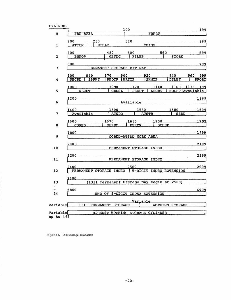
Figure 13. Disk storage allocation
-20-

STORAGl~ ALLOCATION
DISK S~rORAGE ALLOCATION
In ATS, all disk operations are performed in the sector format and the LOcld Mode (with wordmarks). A disk pack has 20 sectors per track and 10 tracks per cylinder, or 200 sectors per cylinder. Since there are 100 cylinders per pack, there are 20,000 sectors per pack to be allocated. The minimum configuration for ATS is one disk drive (two are recommended), yielding a minimum capacity of 20,000 sectors. The first :~o cylinders or 4,000 sectors are allocated to programs and control information. All other sectors are used for storing text. Figure 13 contains a layout of disk storage.
Significant disk areas ares
Ij, Firs't Block Area (sectors 0 through 39). The first 40 sectors are allocated-to contror-information, one sector for each terminal. These sectors hold the tab stop settings, control information for correc1:ions and insertions, control information for text formatting, and the pointer to the first block (disk) in a terminal chain. This pointel: is te:rmed the ANXB (Address of the Next Block), and it occupies the last five positions of each block. Here again, a pointer that is blal~ indicates that there are no sectors chained for a terminal.
20 ~tional :£erminal ~ (sectors 40 through 79).
341 Peripheral Eevice Control (sectors 80 through 99).
441 AfPlication Programs (sectors 100 through 599 and 800 through 1119). Tfil.s clrea contal.ns the main system application programs. An appliccltion program consists of a basic routine plus overlays if needed 41 The basic routine is 20 sectors long, while an overlay is 10 sect:ors. As many overlays as are necessary may be appended to an application program.
5. Bit ~fP (sectors 600 through 799). The bit map is a map of all of the1na~ -tracks allocated for permanent storage and indicates which half-tracks are available.
6. Scheduler, s,stem Subroutines, EUNIT and HSKPG (sectors 1700 thro~MnT. - hl.s lOO-sector sectl.on l.s-re'ad l.nto core in one operation by the bootstrap routine to initialize or restart the system. Sectors 1794 through 1799 of this section contain the ATS COMPOOL (see the section "COMPOOL").
7. Permanent Storage Index (sectors 2000 through 2500 if fourdigit document numbers are used, or 2000 through 6999 if the fivedigit document number option is used). The Permanent Storage Index holds the pointers for each dynamically allocated chain of Permclnent Storage. Each entry in the index is associated with a number assigned to a document by a terminal. These numbers are between 1 and 9999, for thEI four-,ligit option or between 1 and 99999 for the five-digit option.. The sector corresponding to document zero is used to contain the poj.nter for the next half-track available (NHTA).
8. Peripheral Overlay LibrClr~ and User-Written Application Programs ( sectors 1120 through 159 ) :-i?,arts of €fil.s area may be used by perl.pheral programs that may be supplied with future versions of the system. Modifica'tion of the locations of programs stored in this area is discu~)sed in 'the section "Writing Peripheral Programs".
-21-

Location
0 Card Unit and Printer Buffers 333
Scheduler
System Subrouti nes
System Messages
EUNIT
5900
Overlay Area (Application Programs)
7700
Ha I f-Track Area
8600
System Tables
9600 List Area
10000
Dynamically Allocated
100-Character Core Blocks
Variable
Peripheral Overlay Area
16000
Figure 14. Core storage allocation
-22-

9 41 Permanent StoraAe (both upper and lower bounds are determined by the user). If an IB 1301 Disk Storage is installed, all Permanent Storage is on the 1301. Permanent Storage consists of dynamically chained groups of ten contiguous sectors (half-tracks). Messages transmitted between terminals are handled similar to Permanent Storage and also occupy this area.
10. Working Storage (from address determined by user downward) • Working Storage consIsts of single sectors dynamically allocated as explained in the section "Dynamic Disk Location".
CORE STORAGE ALLOCATION
The core storage requirements for l440/l460 ATS are 16,000 positions. A clearer understanding of the organization of the system can be gained by understanding the physical allocation of core storage, which is shown in Figure 14.
Core storage may be divided into eight areas:
1.. Card Buffers, 0 through 332. This area is used for peripheral and main system card ·operations.
2" Main System Programs and EUNIT, 333 through 5899. The Scheduler~the major program-rn the system. Its function is to control the flow of text to and from the terminals, give the reads or writes queued up for the disk file, and schedule work among the various functional (application) programs.
In addition to the Scheduler, the input/output control program (IOCNX) is also in this area. IOCNX is responsible for queuing input/output requests. Al:so in this area are the system subroutines that may be used by application programs. Among the more important subroutines are the following:
Set New Job (SNJBX) is responsible for the queue of new jobs for application programs.
Nt~w Core Block (NCBKX), Head of Free Storage (HDFSX), and Foot of Free Storage (FTFSX) are responsible for the maintenance of the free storage chain of 100-character core blocks.
Nf~xt Disk Block (NDBKX) and Purge Disk Block (PDBKX) are responsible for the pool of availablle disk sector addresses used for Working Storage.
Also in this area, in addition to the main system programs, is a small appliccltion p:rogram called End of Unit (EUNIT), which deletes nonprinting characters preceding the Carrier Return Character at the end of a unit. EUNIT is the only application program that is resident in corE3 while the system is operating.
3.. Overla¥ Area (application programs), 5900 through 7699. All of the app11cat1on-programs, with the exception of EUNIT described above, are re.sident on the disk file. These programs process specific requests from the terminals. When a request is made, SNJBX places a program request in the New Job queue, and when convenient for the system, the appropriate program is read into the Overlay Area and given (:ontrol. The application programs in the system are:
A1:tentio:n (ATTEN) handles the erasing and deleting functions in the system. ATTEN also serves as a preprocessor to other
-23-

application programs and processes system errors or transmission errors.
Bulk Move and Erase (BUKOP) processes the moving and deletion of text in Working Storage.
Correct;ons and Insertions (COINS) processes the calling out of lines and units for correction, and the insertion of lines or units into previously keyed text.
Card to SELECTRIC (CRDSL) creates documents in ATS format from card or unblocked tape input.
Delete (DELET) updates the bit map to indicate available halftracks released by deleted documents.
Files Preprocessor (FILEP) does the initial processing of requests pertaining to Permanent Storage: Store, Get, Delete, Transmit, Message, and Permanent Storage Tape.
Format and Print (FRPRT) generates a formatted text stream for transmission to the terminals.
Get Document (GETDC) retrieves documents from Permanent Storage.
Housekeeping (HSKPG) is the exception that does not respond to requests f~om the terminals. It prepares core storage and initializes the cycling of the system when the system is loaded. It also restarts the system in a system failure situation. Unlike all other overlay programs, HSKPG is not initialized through the New Job queue. Instead, a bootstrap routine is used that brings both the main system routines and HSKPG into core from the disk file and gives control to HSKPG.
Calculate (KLCUT) is an algebraic interpreter that provides arithmetic functions and formula solutions.
Miscellaneous Attention Actions (MISAC) is responsible for setting the terminals to active status, mode setting (that is, Automatic or Uncontrolled Modes), returning the terminal to inactive status, and processing the "next number" request and format control requests (that is, ATTN! and + actions). In addition, MISAC is a preprocessor for FRPRT.
Permanent Storage Print (PERPT) prints a listing of the contents of Permanent Storage on the online printer.
Read Tape (REDTP) reads documents from the Permanent Storage Tape into Permanent Storage on disk.
SELECTRIC to Card (SECRD) translates text entered in card format from terminal code to BCD and produces punched cards, magnetic tape, or online pri'nter output.
Scan Tape (SKNTP) searches the Permanent Storage Tape for a document if a read is requested, or to the end of the file if a write is requested.
Special Print (SPRNT) prints formatted output on the uppercase and lowercase chain printer, if present, or writes it on tape in print image format.
store (STORE) stores documents in Permanent Storage.
-24-

Stc)rage Report (RPORT) prints a list,ing of the contents of Permanent Storage on a terminal.
Write Tape (WRTPP) writes documents from Permanent Storage on disk to the Permanent Storage Tape.
In addi1:ion to these application programs, special purpose application programs may be added to the system.
4. Half-~['rack Area, 7700 through 8599. This area is named for the ten-·sector" elementSor half-tracks that Permanent Storage programs manipulclte in this area. In addition to this use of the area, most applicat:ion programs use it to hold their own respective overlays. Some programs have as many as six overlays. Core restrictions force this second-level overlay technique.
5. System Tables, 8600 through 9599. This area contains fixed tables and ~nd~rcators and is divided into six sections. They are:
a. System Status Table. This is a.general area that contains fixed registers and indicators. "Miscellaneous" would be an appropriate synonym for the table. Among the more important itelms in 1:his area are the pointers to the queues in the list area, and the free storage chain of core blocks. It is described in more detail in the section "System Status Table".
b. Program Status Table (PST). This is a table of the location of every application program. It is described in more det.ail in the sec,tion "Program Status Table".
c. Character Status Table (CST). This table is used in conjunction with ·the Program Status Table to identify the program needed from characters keyed from the terminals. It is described in more detail in the section "Character Status Table".
d. Arm Table (ARM). This table contains five entries, one for each possible disk drive connected to the system. The ARM entries contain the status of the drive and the pointer to the top I/O request for that arm in the list area. It is described in more detai.i in the section "Arm Table".
e. Terminal status Table (TST). This table contains one entry for each possible terminal in the system. Each entry consists of a four-character "Input Buffer" that is used to receive characters when the terminal is in the inactive status. The mode request that initializes the terminal is sensed in this buffer. When the terminal is active, the input buffer is used to keep the line count. It is described in more detail in the section "Terminal Status Table".
f. Multiplexor Status Table (MST). This table is required for communication with the 1448 Transmission Control Unit. There is ,an entry in the table for each line attached to the system. Each entry contains the status for that line (Receive, Transmit, or ~Control) and the address where characters are to be transmitted or :received. In addition, there are a number of control indicators used for various purposes. It is described in more detail in the section' "Multiplexor Status Table".
6. List Area, 9600 through 9999. This area contains the dYnamic list ent:ries tFia-r-make up the New Job, Work in Progress, Arm, and J~vailable queues. Application programs process their text by reading it into "the core blocks and manipulating it there. The number of blocks needed is determined by the number of terminals.
-25-
7. Block Area, 10000 through XXXXX (15899 maximum). ~~his area is compose~ ot t~OO-character, dynamically allocated core blocks used to buffer text between the terminals and the disk filesn Application programs process their text by reading it into the core blocks and manipulating it there. The number of blocks needed is determined by the number of terminals.
8. Peripheral Overlay Area. When all possible core blocks are not require& for terminals, thejhighest positions in core may be used as an overlay area for programs doing peripheral operations. These peripheral operations can include card to tape, tape to printer, or even small unit record type programs that involve some computing between card reading and printing. Card punching introduces system delays and is not recommended while terminals are in operation.
-26-
SYSTEM ,]~ABLES
This section describes, in detail, the contents of tables in the Compool or cownon parameter area in the ATS program. The Autocoder labels of the :Eields described are given in capital letters.
SYSTEM STATUS ~rABLE
The System Status Table is not really a table in the strict sense of the word, but a collection of indicators and registers grouped together for convenience. They are:
LPSA (five positions). Lowest Permanent Storage Address is the disk address specified by the user of the lower boundary of Permanent Storage (low-order zero is understood).
NHTP (five positions). Next Half-Track Possibly is the disk address (low-order zero understood) of the next half-track to be tested for availability in the bit map. It is used to eliminate redundant searches when storing a document.
HPSA (five positions). Highest Permanent Storage Address is the disk address specified by the user of the upper boundary of Permanent Storage (low-order zero understood).
NWSA (five positions). Next Working Storage Sector Address is the disk address (high-order zero understood) of the next sector to be used for Working Storage. At the start of a run it is set equal HWSA. It is documented by NDBKX to i-n.crease the pool of Working Storage Addresses.
LWSA (five positions). Lowest Working Storage Sector Allowed is the uSE~r-specified lower bound of Working Storage (high-order zero understood) •
HWSA (five positions). Highest Working Storage Sector Allowed is the user-specified upper bound of Working Storage (high-order zero understood) •
NTRN (five positions, equated to HWSA). Next Tape Record contains thE~ tape document number of the next document to be written to the archive tape.
OTRM (tE~n positions, wordmark bit). Output Terminal is a table of peripheral output devices attached to a system.
TAPE (t;E~n positions, equated to OTRM, character bits only). TAPE is a t.able of mounted archive tape reels. Each character position represent~3 tape drive numbers zero to nine. When an archive tape is mounted, the alphabetic reel designator (in SELECTRIC code) is placed in the character position corresponding to the drive number.
TTOO (one position, character bits only). This character, 1301 indicator, contains the number of 1301 modulea available. If no 1301 is attached the position is blank.
-27-
FDDN (one position, wordmark bit, equated to TTOO). Five-digiit Document Numbers indicate whether the five-digit option is allowed. (Wordmark indicates five-digit numbers.)
WRUT (one position). Write unit contains the number of the tape drive on which the archive tapes are written.
MACH (one position). MACH describes the computer on which the system is operating. A 6 indicates the 1460, a 4 the 1440. A wordmark indicates the translate instruction is installed on the machine: no wordmark indicates the translate instruction is not installed. The system will adjust its instructions automatically to conform to the appropriate system configuration.
ATLI (two positions). Number of Attached Lines contains the number of lines attached to the 1448 for purposes of setting the groupmark/wordmark in the Multiplexor Status Table.
NAVB (two positions). Number of Available Blocks is the count of core blocks in free storage at anyone time.
ADPR (three positions). This field contains the address of the first character of the peripheral program. It is set by MISAC 1Nhen a new peripheral program is called in by terminal O.
DATE (six positions). This field is set by the HSKPG program w.ith the date entered by the computer operator at the 1447 Console. It is used by STORE to date documents when they are entered into Permanent Storage.
SCLK (two positions). Simulated Clock is used by the Schedule:r to keep track of the amount of time available for disk operations. It is set to 99 (100 milliseconds) each time the Scheduler is entered, and is decremented an appropriate amount for eve.ry function that is performed. It is checked just before disk operations are attempted. Forty milliseconds are allowed for each disk operation, making two operations possible if no other work was done.
MODE (one position). A wordmark on the MODE switch indicates 'that the Scheduler is operating; no wordmark indicates that an application program is operating. This indicator is used by some of the system subroutines and IOCNX to perform certain operations that are done only for the Scheduler. In addi,tion, some of the subroutines will trick other subroutines into thinking they are working for Scheduler to get additional operations performed. The 1- and 2-bits of MODE are used as request bits for servicing the peripheral program: a l-bit means branch to the address in ADPR after every 1448 scan; a 2-bit means branch whenever lOOms of available computer time exists.
OVBZ (one position). A wordmark in the Overlay Busy indicator is set by the Scheduler whenever a program is in, or is in the p:rocess of being read into, the overlay area. With the switch on, the Scheduler will not attempt to read in another program until the current one is finished with its work. The Scheduler turns the switch off when an application program returns control, indicating that its work is done.
-28-

PROV (three positions). Program in Overlay is set to the Program Status Table Location (PST number) for the program currently operating in the overlay area (see the section "Program Status Table"). The rationale for this indicator is that two requests might appear in t:he NJB list for the same program, making a selcond reading of the program unnecessary. The Scheduler checks the PROV indicator for every NJB ent:ry that it processes.
HDCC (five positions). Head of Clear Chain is the disk address (highorder zero understood) of the top sector of a chain of sectors to be purged. It is set to blanks if no sectors are to be purged.
HDPT (three positions). The Head Pointer points to the top entry of the free storage chain of core blocks.
FTPT (three positions). The Foot Pointer points to the foot of the free storage chain of core blocks.
NDPT (three positions). The Next Disk Pointer points to the top currently available entry in the pool of sector addresses used for Working Storage on disk.
NBDA (one position). Number of Blocks of Disk Addresses is the number of core blocks being used to hold the pool of Working Storage disk addresses.
NJPT (three positions). The New Job Pointer points to the top entry in the New Job list.
WPPT (three positions). The Work in Progress Pointer points to the top entry of completed disk input/output list.
AVPT (three positions). The Available Pointer points to the top available (free storage) entry in the list area.
The above indicat.ors should not ordinarily be read or changed by an applica.tion program. Control should be given instead to the particular subrout,ine that is responsible for the indicator, such as SNJBX for the New Job queue.
PROGRAM STATUS TABLE
The Program Status Table (PST) is a contiguous list of every application program that can be operated through the New Job queue. The elements of this table are three characters long. If the program is resident in core:, such as EUNIT, the three charac'ters contain the core address of the first instruction. However, as is usually the case, if the program is resident on the disk pack, the three characters reference the disk addrE~ss with one low-order and ,two high-order zeros understood. Since the overlay area holds 20 sectors, the sector count is understood to be 20 regardless of program length. If a program exceeds 20 sectors, it must read in its own lO-sector overlays into the half-track area.
Two indicators are used in the PST. A w,ordmark in the high-order position indicates that the entry is a core address and the program is resident in core. No wordmark indicates a disk address. This indicat:or is called Program Location. Another indicator is Program Busy (BUSY). Obviously, it is possible for two requests for the same program to be in the New Job queue at the same time. In such a situation, unless precautions were taken, a program could be processing two requests at once. To prevent this from occurring, the BUSY-bit
-29-
(wordmark in the tens position of the entry) is turned on when4aver a program is operating. Other requests for the program wait in the queue until it is available.
In the Autocoder language, an example of an entry for a core program would appear as follows:
PEUNIT EQU 0 DCW +EUNIT
The label for the entry is prefaced by a P (meaning PST position for EUNIT) to avoid presenting label ambiguity to the assembler. Equating PEUNIT to zero is in reality equating the label to the high-order position of the DCW statement following (assuming the table beqan at zero). Since each entry is three characters long, it will havE~ its high-order position in increments of three from the beginning of the table. Thus PEUNIT is the first entry in the table, as the first entry is equated to zero. +EUNIT means the high-order address of the field with that label, in this case an instruction. The DCW s1:atement contains the core address in this case.
A disk program entry would appear like this:
PATTEN EQU 3 DC @020@
Note: In this example, the entry is a DC statement that is assembled as-a three-character field without a wordmark. The @ signs preceding and following the 020 indicate a literal. Attention is the sec:ond entry in the table and is, therefore, equated to three. In this case, the DC statement implies a disk address.
The order of the entries specifies program priority. Thus, PATTEN equated to three has a higher priority than PMISAC, which is equated to six.
The number that the PST label is equated to is used in conjunct:ion with the Character Status Table (see below) to identify a program with keyed terminal characters. Note the ease with which a program can be added to the system. An entry is made in the PST; another is made in the Character Status Table; the program is read onto the disk1 and a new function is added to the system.
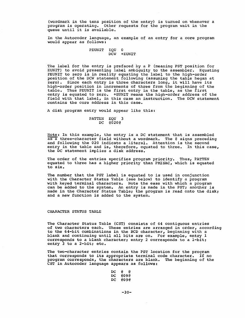
CHARACTER STATUS TABLE
The Character Status Table (CST) consists of 64 contiguous entries of two characters each. These entries are arranged .in order, according to the 64-bit combinations in the BCD character, beginning with a blank and continuing until all bits are on. For example, entry I corresponds to a blank character1 entry 2 corresponds to a I-bit; entry 3 to a 2-bit; etc.
The two-character entries contain the PST location for the pro9ram that corresponds to its appropriate terminal code character. If no program corresponds, the characters are blank. The beginning elf the CST in Autocoder language appears as follows:
DC @ @ DC @09@ DC @09@
-30-

One of the responsibilities of the Attention program (ATTEN) is to interpret AttE~ntion actions. This interpretation is accomplished first by identifying the bit code in the character following an Attention character and then by finding the CST entry that corresponds to that character. If the entry is blank, the Attention action is illegal.. OthE~rwise, a New Job entry is set for the program designated by the CST entry.
To ente~r a new program into the system, the PST location must be inserte~d into the CST entry corresponding to the character that will be used to request the function.
ARM TABLE
The AID1 Table consists of five entries of 20 characters each, one for each possible arm (Disk Drive Access Arm) in the system. An ARM entry is shown in Figure 15.
Character 0-2 3 4 5-7 8-9 10-18 19
NEPT NUMT ARMS ARMP ARMF SVAC Spare
Figure 15. ARM Table entry
The fields in an entry are:
NEPT (~t:hree characters, positions 0 through 2). The Next Entry Pointer points to the top entry for the arm corresponding to this table entry (see "List Entries" below).
NUMT (one character, position 3). It is possible, because of a failure of a disk drive or a program specifying an incorrect sector address, for a disk error condition to arise. Should this occur, the Scheduler will reseek and retry the operation seven times. The count of tries is kept in the Number of Tries position of the appropriat~ ARM entry.
ARMS (one character, position 4). The ARM Status character indicates whether the arm is seeking (wordmark) and the type of operation that is 'waiting. A 1 indicates a read waiting1 a 2 indicates a w:rite waiting; and a blank indicates nothing is waiting@
ARMP ('three characters, positions 5 through 7). Since the direct seek feature is used, it is important to know the Arm Position in order to make the necessary computation. The ARMP register holds the hundreds, thousands, and ten thousands position of the current sector address, rounded down to an even cylinder number.
-31-

ARMF (two characters, positions 8 and 9). Arm Failures are used to keep a record of the number of I/O requests that required cit least one reseek. This indicator is a diagnostic indicator. It makes it possible to request maintenance before a drive fails altogether.
SVAC (nine characters, positions 10 through 18). This portion of the ARM entry is called Saved Address. and Count. A disk control field is kept in SVAC so that it may be restored immediately after a disk operation.
SPARE (one character, position 19). This character is reserved for possible expansion of the system.
All 1311 input/output requests are placed in the arm queue determined by the ten-thousands digit of the disk control field1 0 and 1 to arm queue 0, 2 and 3 to arm queue 1, 4 and 5 to arm queue 2, 6 and 7 to arm queue 3, and 8 and 9 to arm queue 4. This scheme is also employed for 1301 input/output requests except that all those which would go to arm queues 0 and 1 are placed in arm queues 3 and 4 respectively. Since most systems utilizing 1301 Disk Storage have two 1311 Disk Storage Drives this scheme places all 1311 input/output requests in arm queues 0 and 1 and all 1301 input/output requests in arm queues 2, 3 and 4.
TERMINAL STATUS TABLE
The Terminal Status Table (TST) consists of one to 40 entries of five characters each, one for every attached terminal in the system. The last character in every entry is a groupmark/wordmark.
Inactive Status
As far as the 1448 and the processor are concerned, a terminal is never offline. The so-called inactive status is an invention that is completely contained in the program. Because of this, the running address for every inactive line must be set. When a terminal is inactive, its running address is set to the first character of its respective TST entry. In this situation, the TST entry is termed the Input Buffer (INBF). As characters are entered into the system, the INBF fills up until the running address is pointing to the groupmark/wordmark. All subsequent characters entered are lost. When the Carrier Return is transmitted from the terminal, the Scheduler resets the running address to the first INBF character again. However, a terminal may request to go online and, because of this, the Scheduler will check the INBF for the exact sequence ATTN a CR or ATTN u CR. If the sequence is sensed, all succeeding text will be entered into a core block, and the terminal will be considered to be active. If not, the running address is reset to the first INBF character for that terminal.
Active Status
A terminal is placed in active status when the initial ATTN a o:r ATTN u action is taken when in the offline status. When a terminal .is active, its TST entry is used to count the number of lines or units
-32-

entered. The ATTN a or u CR is considered the first line, and ~ll subsequent lines or units cause the number in the TST entry (now called LINE) to be incremented. 'l'his number is used with the line count stored in each block to locate specific lines for correction or inser'tion.
NULTIPLEXOR STATUS TABLE
The Multiplexor Status Table (MST) is the communication between the 1448 and the processor. In addition, a number of indicators that are very important to the program occupy this area. The table itself consists of one to 40 entries of ten characters each, or one entry for each line attached to the 1448. A groupmark/wordmark is placed immediately af"cer the entry corresponding to the last attached line. An MST E~ntry is shown in Figure 16.
Character Bit B
A
8
4
2
a 2 3 4
STAC RUNA
Figure 16. Multiplexor Status Table (MST) entry
The fields in an entry are:
5
SVRA
6 7 8 9
AUTO STOP MSGW
TACT ATFL BALL
COIN PACT Spare
STAC (one character, position 0). This character indicates the status for the line (see the section "The Multiplexor" for the possible status characters) •
RUNA (three characters, positions 1 to 3). RUNA points to where the 14,48 may deposit or pick up characters.
SVRA (three characters, positions 4 to 6). SVRA is the mnemonic for Saved Running Address. These positions are used for temporary storage of a running address that will replace the current one. An example would be to save the running address to a core block while the current: running address points to a system message in the message area~
AUTO (B-bit, position 7). If the AUTO-bit is one, the terminal is in the Automatic Mode. Off indicates the Uncontrolled Mode.
TACT (A-bit, position 7). is in active status. active.
This bit indicates whether or not a terminal If the TACT-bit is on, the terminal is
-33-
COIN (numeric, position 7). This indicator gets its name from the COINS (Corrections and Insertions) program, which sets th43 field to I if a correction is in progress, or to a 2 if an insertion is in progress. The FILEP program will set it to 4 if a d.ocument ident is being entered, or to 8 if a document is in the process of being deleted from Permanent Storage. The DUKOP program will set COIN to 3 if a bulk move has been requested, or to 9 in the case of a bulk erase. The value of this indicator is immediately apparent in view of the fact that an application program cannot remain in the overlay area while it is waiting for operator response, as this would cut off all functions to all othe:r terminals.
STOP (D-bit, position 8). This bit is set by certain programs when they have finished generating output. r.!.'he Scheduler, upon sensing the STOP-bit, will reactivate the program in PACT after the Attention character is received.
PACT (numeric, position 8). PACT is the mnemonic for Program Activation Required. PACT is used in conjuncion with STOP to reacti'vate certain programs.
ATFL (A-bit, position 8). The Attention Flag is set by the Scheduler whenever the Attention key is depressed, and indicates that an Attention action is being entered and must be interpreted and processed when the Carrier Return is received.
MSGW (D-bit, position 9). This bit, l-/essage Waiting, is set by the STORE program to indicate that a message has been queued up for that terminal. Application programs, sensing this bit, insert the characters (MSG) in certain system messages transmitted to the terminal.
BALL (A-bit, position 9). This bit indicates the type of SELECTRIC printing element on the terminal. If the bit is on, a manifold or similar printing element is indicated, and the numeric one is used in all system-generated messages sent to the term~nal. If the bit is off, the lowercase L is used for the numeral one.
SPARE (numeric, position 9). These bits are reserved for possible expansion of the system.
LIST ENTRIES
Availability Entry
The list area is organized in the manner described at the end of the section "List Processing". An entry in the free storage chain of list entries contains two fields:
Not Referenced (seven characters, positions 0 through 6). This area conta~ns whatever was entered into it previously. 'l'he entries are never cleared.
Pointer (three characters, positions 7 through 9). This pointer po~nts to the next entry in the queue. A blank pointer indicates the end of the list.
-34-
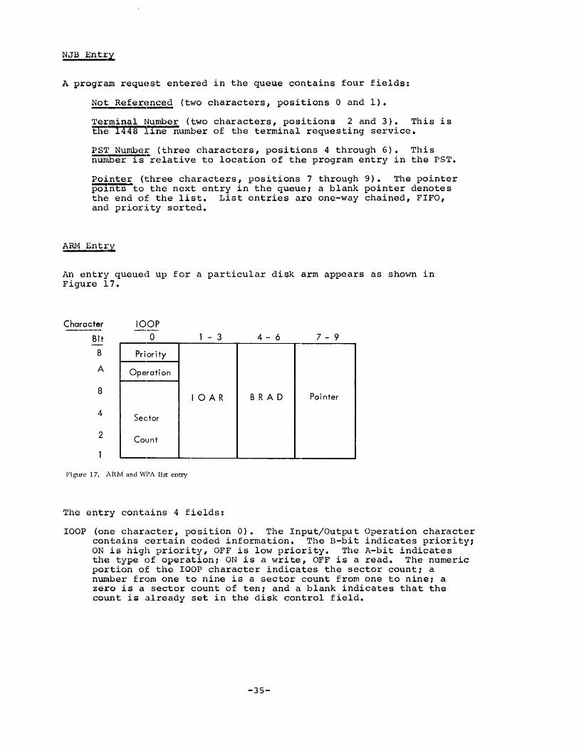
NJB EntI~
A program requE~st entered in the queue contains four fields:
~ Ref~~E~ (two characters, positions 0 and 1).
Te:t'minal Number (two characters, positions 2 and 3). This is thE~ 1448 ll..ne number of the terminal requesting service.
PS'J? Number (three characters, positions 4 through 6). Thi s numilier l..s-relative to location of' the program entry in the PST.
Pointer (three characters, positions 7 through 9). The pointer PQ1~to the next entry in the queue, a blank pointer denotes the end of the list. List entries are one-way chained, FIFO, and priority sorted.
ARM Entr~
An entry queued up for a particular disk arm appears as shown in Figure 17.
Character
Bit
B
A
8
4
2
lOOP
o Priority
Operation
Sec:tor
Count
Figure 17. ARM and WPA list entry
1 - 3
10 AR
The entry contains 4 fields:
4 - 6 7 - 9
BRA D Pointer
lOOP (one character, position 0). The Input/Output Operation character contains certain coded information. The B-bit indicates prioritY1 ON is high priority, OFF is low priority. The A-bit indicates the type of operation; ON is a write, OFF is a read. The numeric portion of the lOOP character indicates the sector count; a n~\ber from one to nine is a sector count from one to nine; a zero is a sector count of ten; and a blank indicates that the count is already set in the disk control field.
-35-

IOAR (three characters, positions 1 through 3). The Input/Output Area is the address of the high-order positions of the disk control field (the asterisk or lozenge) •
BRAD (three characters, positions 4 through 6). This field is the Branch Address where control is to be returned when the input/output operation is complete.
Pointer (three characters, positions 7 through 9). The pointer points to the next entry in the queue, with a blank pointer indicating the end of the chain. ARH entries are FIFO and priority sorted.
WPA Entry
The entries in the queue of completed I/O (Work in Progress) are simply ARM entries rechained in the WPA queue. In other words, ARM and WPA entries have exactly the same information. They are simply queued behind different pointers. WPA entries are FIFO.
-36-
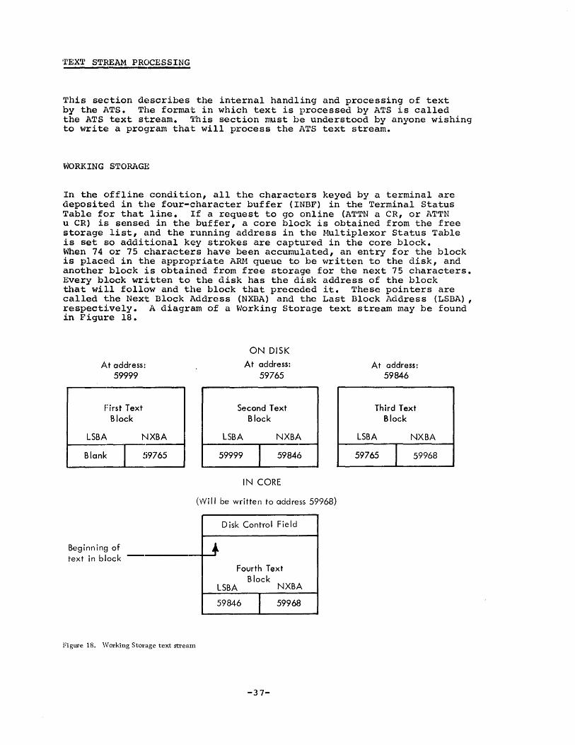
TEXT STREAM PROCESSING
This sec~tion describes the internal handling and processing of text by the A.TS. The format: in which text is processed by ATS is called the ATS text st:ream. This section must be understood by anyone wishing to write: a pr09ram tha't will process the ATS text stream.
WORKING STORAG:8
In the c)ffline condition, all the characters keyed by a terminal are deposited in the four-character buffer (INBF) in the Terminal Status Table for that line. If a request to go online (ATTN a CR, or ATTN u CR) is sensed in the buffer, a core block is obtained from the free storage list, clnd the running address in the Multiplexor Status Table is set so additional key strokes are captured in the core block. When 74 or 75 characters have been accumulated, an entry for the block is placed in the appropriate Aru1 queue to be written to the disk, and another block is obtained from free storage for the next 75 characters. Every bl.ock written to the disk has the disk address of the block that will follow and the block that preceded it. These pointers are called t:he Next Block Address (NXBA) and the Last Block Address (LSBA), respectively. A diagram of a Working Storage text stream may be found in Figure 18.
A.t address: 59999
First Text Block
LSBA. NXBA
I---B-'a-n-k~'9765
Beginnin~~ of text in bllock
Figure 18. Working StoI'age text stream
ON DISK
At address: 59765
Second Text Block
LSBA NXBA
59999 I 59846
IN CORE
(Will be written to address 59968)
Disk Control Field
~ Fourth Text
Block LSBA NXBA
59846 I 59968
-37-
At address: 59846
Third Text Block
LSBA NXBA
59765 I 59968
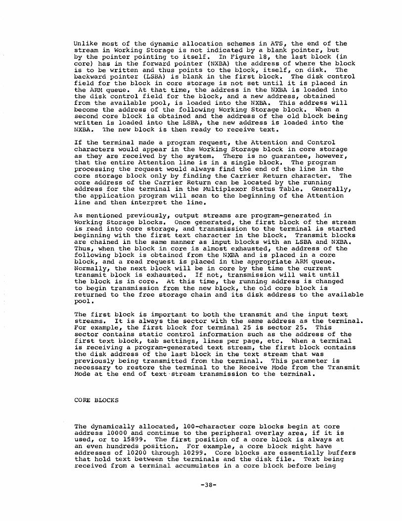
Unlike most of the dynamic allocation schemes in ATS, the end of the stream in Working Storage is not indicated by a blank pointer, but by the pointer pointing to itself. In Figure 18, the last block (in core) has in the forward pointer (NXBA) the address of where thE~ block is to be written and thus points to the block, itself, on disk. The backward pointer (LSBA) is blank in the first block. The disk control field for the block in core storage is not set until it is placed in the ARM queue. At that time, the address in the NXBA is loaded into the disk control field for the block, and a new address, obtained from the available pool, is loaded into the NXBA. This address will become the address of the following Working Storage block. When a second core block is obtained and the address of the old block being written is loaded into the LSBA, the new address is loaded into the NXBA. 'l°he new block is then ready to rece i ve text.
If the terminal made a program request, the Attention and Contr()l characters would appear in the Working Storage block in core storage as they are received by the system. There is no guarantee, however, that the entire Attention line is in a single block. The program processing the request would always find the end of the line in the core storage block only by finding the Carrier Return character$ The core address of the Carrier Return can be located by the running address for the terminal in the Multiplexor Status Table. GeneJ::'ally, the application program will scan to the beginning of the Attention line and then interpret the line.
As mentioned previously, output streams are program-generated in Working Storage blocks. Once generated, the first block of the stream is read into core storage, and transmission to the terminal is started beg~nning with the first text character in the block. Transmit blocks are chained in the same manner as input blocks with an LSBA and NXBA. Thus, when the block in core is almost exhausted, the address of the following block is obtained from the NXBA and is placed in a core block, and a read request is placed in the appropriate Aru-l queuE~. Normally, the next block will be in core by the time the current transmit block is exhausted. If not, transmission will wait until the block is in core. At this time, the running address is changed to begin transmission from the new block, the old core block is returned to the free storage chain and its disk address to the clvailable pool.
The first block is important to both the transmit and the input text streams. It is always the sector with the same address as the 1:.erminal. For example, the first block for terminal 25 is sector 25. This sector contains static control information such as the address of the first text block, tab settings, lines per page, etc. When a terminal is receiving a program-generated text stream, the first block contains the disk address of the last block in the text stream that was previously being transmitted from the terminal. This parameter is necessary to restore the terminal to the Receive Mode from the ~~ransmit Mode at the end of text-stream transmission to the terminal.
CORE BLOCKS
The dynamically allocated, 100-character core blocks begin at core address 10000.and continue to the peripheral overlay area, if it is used, or to 15899. The first position of a core block is always at an even hundreds position. For example, a core block might havE~ addresses of 10200 through 10299. Core blocks are essentially buffers that hold text between the terminals and the disk file. Text bE~ing received from a terminal accumulates in a core block before being
-38-

written to the disk pack. Text being transmitted is read or generated in these blocks.
In addition, application programs work with raw text and generate output streams in these blocks.
Block in Free Storage
All core! blocks are initially located in a free storage chain. Free storage is two--way chained, with the HDPT (Head Pointer) and the FTPT (Foot Pointer) pointing to the ends of the chain (see Figure 19).
A block in freE::! storage contains two control fields:
BKCB (three characters, positions 1 through 3). The Backward Core Block is the backward chaining address in the block and points to\Olard thE::! top of the chain. The first block in the chain contains a blank BKCB.
FWCB (three characters, positions 4 through 6). The Forward Core Blc)ck points toward the bottom of the chain. The last block in thE~ chain contains a blank FWCB.
Block in Receive Status
A core block in Receive status is accumulating text from a terminal. The first ten characters comprise the disk control field; the last ten characters are the disk chaining addresses; and five characters are used for control, leaving 75 characters per block for text (see Figure ~W).
Since a block is written in the Load Mode, the 90 characters following the disk control field are written out. A block in Receive status has several important locations and fields:
Asterisk (one character, position 0). The first character of the disk control field contains an asterisk, since the alternate code is not used.
SADD (six characters, positions 1 through 6). The Sector Address portion of the disk control field contains the full six-character address of the sector to which the block is to be written.
SCNT (three characters, positions 7 through 9). The Sector Count is al'>lays 001 for a core block.
FTXC (one character, position lO). The First Text Character label identifies the address where the text begins in the block.
LTXC (one character, position 84). The Last Text Character label identifies the location of the last valid text character.
Groupmarks (two characters, positions 83 and 84). The groupmarks at LTXC-l and LTXC turn on the Early Warning Indicator when· characters from the -terminal are stored over them.
GroupmaJck/Wordmark (one character, position 85). The groupmark/wordmark will stop the reception of text and turn on the End-of-Storage bit in the status character if the multiplexor attempts to store a (:::haracter over it.
-39-
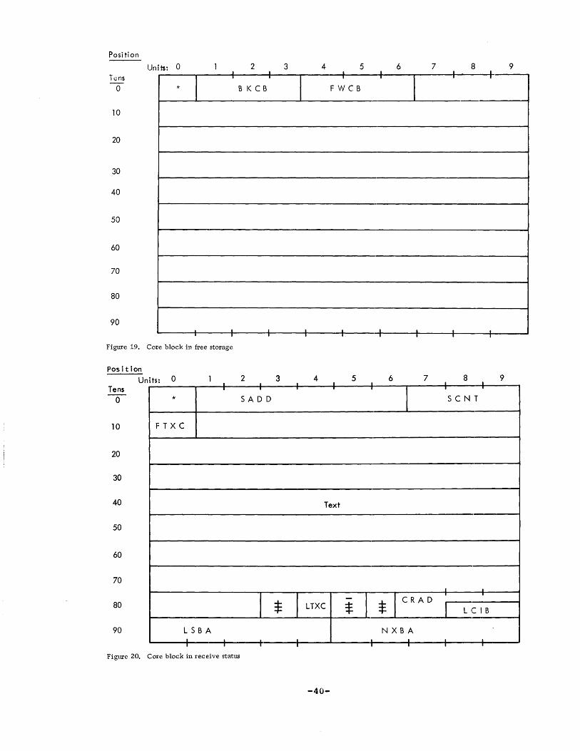
Posi tion
h:ns o
10
20
30
40
50
60
70
80
90
Units: 0 I
I ,
*
I I
Figure 19. Core block in free storage
Position
Tens Units' 0
I . o *
10 F T X C
20
30
40
50
60
70
80
90 LSBA I I I
2 I I
B K C B
I I
2 . SAD D
I . I
Figure 20. Core block in receive status
3
3
*
4 5 6 7 8 9 · I I -+ 1
,
I F weB
. · I I I . I · I
4 5 6 7 8 9 I I I I I
T
I I
seN T
Text
I I
I LTXC - I * I CRAD
. . $ I Lei B
N X B A . . T I I I .-
-40-
Groupmark (one character, position 86). This position can be used as an indicator, but it is currently a spare.
CRAD (one character 9-nd zone-bits of the next two, positions 87 through 89). CRAD contains the Core Address of the core block that preceded the current one. Since the core blocks originate at eVlen hundreds, only the first character and the two following zone-bits are needed. The address references the asterisk (position 0) character. This address is used to locate characters in a previous block. Although the previous block has been written to the pack and has been returned to the free storage chain, there is a possibility that the block has not been reassigned. The Scheduler increases the odds by always releasing a block to the foot of free storage. (Blocks are always assigned from the head.) If the block is still there, a time-consuming disk read can be avoided. This is a tally of the number of lines or units that begin in the block, and it is used with LINE in the TST to locate specific lines for correction or insertion.
LSBA (five characters, positions 90 through 94). The Last Block Address is the backward disk pointer, pointing to the preceding block. The first block on the disk chain has a blank LSBA. (This should not be confused with the "First Block Area" discussed below. )
NXBA (five charapters, positions 95 through 99). The Next Block Address points forward to the succeeding disk block. While in co:re, NXBA is the address of where the core block is to be written when filled. Just before writing, it is changed to point forward (in anticipation) to the next disk block in the chain. The last block of an input: chain has an NXBA equal to its sector address.
Block in Transmit Stat~
A block in Transmit status (see Figure 21) has several important fields and locations:
SADD (six characters, positions 1 through 6). This is the sector address, and it i.s set by the Scheduler prior to reading a block from the pack.
SCNT (three characters, positions 7 through 9). SCNT is the sector count portion of the disk control field and is always 001.
FTXC (one character, position 10). FTXC is the label for the First Text Character.
TREW is composed of a record mark followed by a 1. When the 1448 senses the record mark in its buffers, it sets the EOB (WM) bit for the appropriate line and request.s an interrupt. The Scheduler, upon sensing that. a 1 follows the record mark, will immediately queue up the next block to be read from the pack, setting the SVRA in the MST t.O the core block address for the new block. Application programmers need not be concerned with setting TREW. Th4; Scheduler will set it automatically.
LTXC (one character, position 84). The Last Text Character label identifies the location of the last position that may contain a character for transmission.
-41-
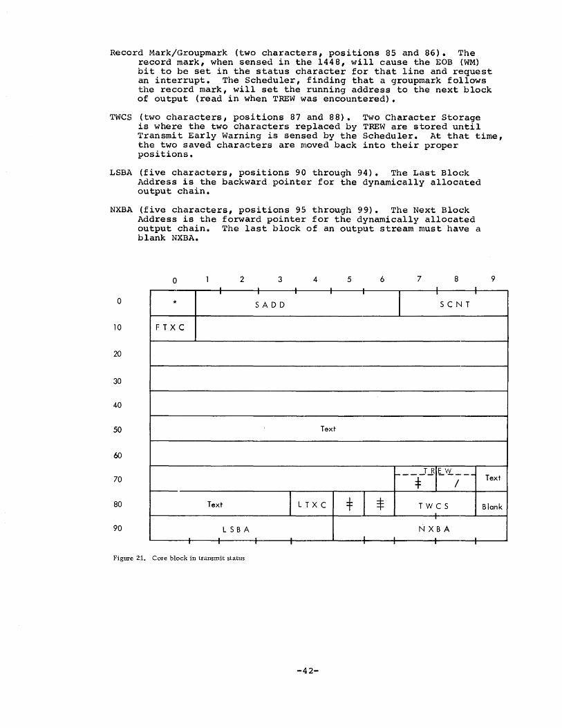
Record Mark/Groupmark (two characters, positions 85 and 86). '1~he record mark, when sensed in the 1448, will cause the EOB (WM) bit to be set in the status character for that line and request an interrupt. The Scheduler, finding that a groupmark follows the record mark, will set the running address to the next block of output (read in when TREW was encountered).
TWCS (two characters, positions 87 and 88). is where the two characters replaced by Transmit Early Warning is sensed by the the two saved characters are moved back positions.
Two Character Storage TREW are stored until Scheduler. At that time, into their proper
LSBA (five characters, positions 90 through 94). The Last Block Address is the backward pointer for the dynamically allocated output chain.
NXBA (five characters, positions 95 through 99). The Next Block Address is the forward pointer for the dynamically allocated output chain. The last block of an output stream must have a blank NXBA.
o 2 3 4 5 6 7 8 . I . . I I
o I I I I -r
1 I I
* SADD seN T
10 F T X C
20
30
40
50 Text
60
70 I-- __ :j:J..BIL'iY.; __
Text I L T XC =F I * TWCS . 80 I
90 LSBA N X B A . .
-- I I I I I I
Figure 21. Core block in transmit status
-42-
9
Text
Blank

ATS TEXT-HANDLING CONVENTIONS
Receive Status
The conventions followed in receiving and storing text are that the text in a block always begins with FTXC and ends with the first groupmark. Th,e latter convention is important to note because it is quite common for text in a block not to extend all the way to LTXC. If corrE~ctions or insertions are made, blocks must be split apart, leaving some partially filled. An application program scanning text should finish the scan of a block with the first groupmark encountered.
Some Attention actions are imbedded within the text stream and serve to control the Format and Print program (FRPRT) when it is generating output. These actions are: ATTN a, ATTN u, ATTN +, ATTN h, ATTN f. The AttE:!ntion character will precede the action indicator and should be checked for by an application program.
In order to start each line with a known condition, a Downshift always is inserted af'ter a Carrier Return. At the beginning of a line or unit, this Downshift character is wordmarked. In the Automatic Mode, all Carrier Re'turns are also wordmarked. As an example, a line in the Unc()ntrolled Mode might appear as follows:
Wordmarks: Characters: ]<> E g$ OR @ZU @OJUK]
Translation: Carrier Return, wordmarked Downshift, Upshift, "N", Downshift, "ow is the time.", Carrier Return. (Characters underlined in the example are shown in quotation marks in the t:ranslation.)
An example in the Automatic Mode would be:
Wordmarks: Characters: ]]<>2<C rQT VQSM@]<R$OSAG VQSM@ NOSAK]]
Translation: Wordmarked Carrier Returns (2), wordmarked Downshift, Upshift, "I", Downshift "f you don't" Wordmarked Carrier Return, Downshift, "swing, don't ring", Wordmarked Carrier Returns (2). (Characters underlined in the example are shown in quotation marks in the translation.)
Note thclt in this example the imbedded Carrier Returns are wordmarked.
Transmit Status
Since a record mark sets the EOB (WM) bit, it is used for Transmit Early Warning, to end a block, and to end system meSsages. The character immed.iately following the record mark tells the Scheduler what needs to be done next.
A 1 following the record mark denotes Transmit Early Warning. The Scheduler will queue the next block of output for a read from the pack and restore the two saved characters.
A 2 following the record mark indicates the end of a system message, a~d the Scheduler moves the saved running address to the running address and sets the status to Receive-Idle.
-43-
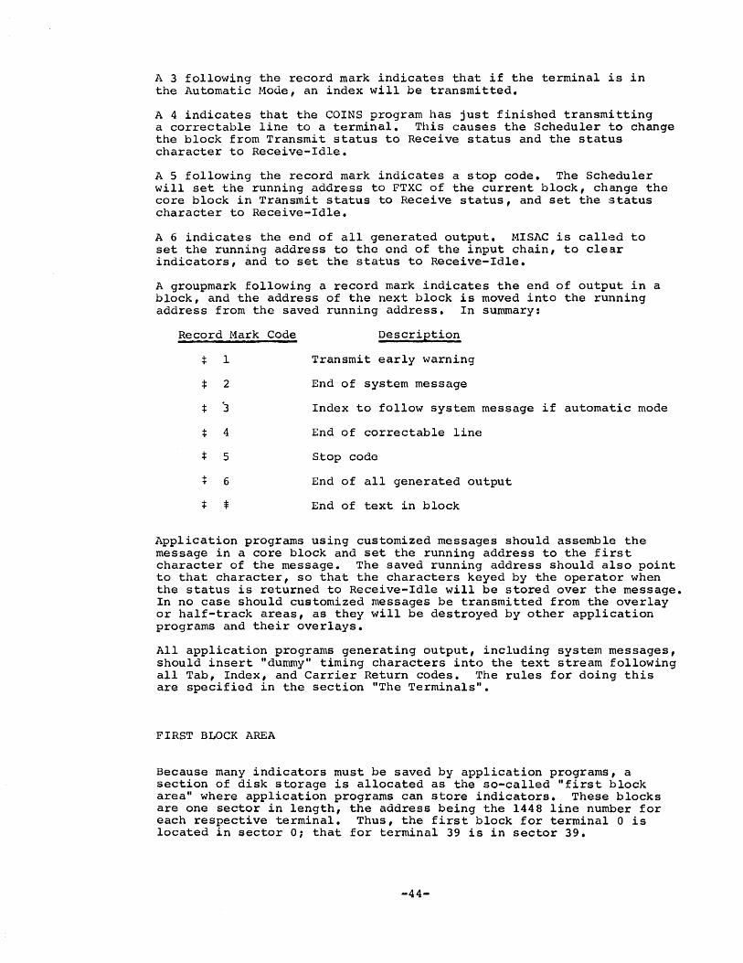
A 3 following the record mark indicates that if the terminal is in the Automatic Mode, an index will be transmitted.
A 4 indicates that the COINS program has just finished transmitting a correctable line to a terminal. This causes the Scheduler to change the block from Transmit status to Receive status and the status character to Receive-Idle.
A 5 following the record mark indicates a stop code. The Scheduler will set the running address to FTXC of the current block, change the core block in Transmit status to Receive status, and set the status character to Receive-Idle.
A 6 indicates the end of all generated output. MISAC is called to set the running address to the end of the input chain, to clear indicators, and to set the status to Receive-Idle.
A groupmark following a record mark indicates the end of output in a block, and the address of the next block is moved into the running address from the saved running address. In summary:
Record Mark
* I
* 2
* '3
* 4
* 5
:j: 6
* =I:
Code Description
Transmit early warning
End of system message
Index to follow system message if automatic mode
End of correctable line
8.top code
End of all generated output
End of text in block
Application programs using customized messages should assemble the message in a core block and set the running address to the first character of the message. The saved running address should also point to that character, so that the characters keyed by the operator when the status is returned to Receive-Idle will be stored over the message. In no case should customized messages be transmitted from the overlay or half-track areas, as they will be destroyed by other application programs and their overlays.
All application programs generating output, including system messages, should insert "dummy" timing characters into the text stream following all Tab, Index, and Carrier Return codes. The rules for doing this are specified in the section "The Terminals".
FIRST BLOCK AREA
Because many indicators must be saved by application programs, a section of disk storage is allocated as the so-called "first block area" where application programs can store indicators. These blocks are one sector in length, the address being the 1448 line number for each respective terminal. Thus, the first block for terminal 0 is located in sector 01 that for terminal 39 is in sector 39.
-44-

Five fields in the first block are important to most application programs:
TABS (20 characters, positions 0 through 19). The first 20 characters of the first block contain the Tab Setting for the terminal. These characters may be thought of, and are used as, a 6 x 20 binary matrix. Each bit is in one-to-one correspondence to the first 120 positions on the typewriter carriage. A bit in any position indicates that a tab stop is set in the corresponding position on the typewriter.
The matrix is actually divided in half, the first 10 character positions corresponding to the first 60 tab settings, and the latter the next 60 settings. Beginning with the I-bit in character position 0, successive tab settings are indicated across the 1-rc)w to position 9, then jump back to the 2-bit in position o. The 2-ro'fI continues the same as the I-row, and successive tab settings continue from the 2-row in character position 9 to the 4-bit in character position O. This procedure continues until the B-bit is reached in character position 9. From there, successive tab settings are found beginning with the l-~it in character position 10 and continuing across the I-row to character position 19 and so on. These settings can be diagrammed as fc)llows:
~ Characters 0-9
B 50---------59 A 40---------49 8 30---------39 4 20---------29 2 10---------19 1 0--------- 9
Characters 10-19
110---------119 100---------109 90--------- 99 80--------- 89 70--------- 79 60--------- 69
The setting of the tab stops in TABS is accomplished by MISAC when it interprets the appropriate attention action.
LLDA (five chiaracters, positions 69 through 73). Any program generating multiple block output sets the Last Line Disk Address to the disk address (with high-order zero understood) of the end of the input chain. After such a program writes out the last input block, it sets LLDA to the value of that block's SADD. After the output has been transmitted, the MISAC program will be read in. MISAC will perform housekeeping on the indicators, read in the block referenced by LLDA, set the running address so that the Attention action that initiated the output generating program will be stored over by the next characters entered by the operator, and set the status to Receive-Idle. Thus, everything is set so that keystrokes may again be received from the terminal.
LLRF (four characters, positions 74 through 77). The Last Line RE~ferenced is the line number last requested by the terminal and is set by the COINS program.
LLRL (seven characters, positions 78 through 84). The Last Line RE~ferenced Location is the disk and character- address of the s1:.art of the last line that the COINS program located for corrections or insertions.
LI~RL consists of a disk address (five characters) with one highorder zero understood, and the relative character address within the block. Because core blocks originate at even hundreds, the character addresses will always be the same from block to block. (Character addresses are the two low-order positions of a core block address.) Thus, with the disk address, a block may be
-45-
read into core in any core block and the precise line that was last referenced may be located. LLRL could be diagrammed as follows:
27 29753
The number 29753 in the above example implies the disk control field:
*029753001
This is the sector address of the last referenced block.
The number 27 in the example is the numeric portion of the two low-order characters of a core address. It can be used with thp high-order character and two low-order zones of the core block address into which the disk block is read. For example:
Zone: B B Numeric: 2bb + b27 = K2P
Translation: 102bb + 27 = 10227
This shows how the address 10227, or position 27 in the block that begins at address 10200, could be constructed.
ANXB (five characters, positions 85 through 89). The Address of the Next Block field is the disk address (with high-order zero understood) of the first block of the terminal's chain. This address is initially set by MISAC when the terminal first requests the A or U Mode.
The importance of the tab rack setting is immediately apparent. For example, a program that is formatting text for output must know how many characters a tab will cross to avoid exceeding a specified line width. Dummy characters following the tab are computed according to the number of character positions the print element must move. In addi tion, some applications attach special meaning to tab stops 4' An example of the latter case would be entering text in the form of card images where the tab key is analogous to the skip key on a keypunch.
LLRF, LLRL, and ANXB are specially useful to a program that must: search through a terminal's text stream for a particular line or unit. Since the end of the stream has a known location (the running address), there are three known points in the chain: the beginning (ANXB), the last line referenced (LLRF, LLRL), and the end (running address). Thus, a search can begin at whichever point is closest to the de!sired line by following the chaining addresses forward or backward.
All of the indicators in the first block have special meaning tel the standard system application programs. Although these indicators, may be used by any application program, they should not be altered by these programs, except if the greatest care is that no undesired sideeffects will occur.
WARNING: If an application program alters the text stream in such a way as to make LLRL invalid, LLRF and LLRL m:lst be set to all bl.anks.
PERMANENT STORAGE
Permanent Storage is composed of dynamically allocated blocks of 900 characters (ten sectors) each. These blocks are termed half-tracks since each occupies one-half of an IBM 1316 Disk Pack track. The beginning of every chain is to be found in the Permanent Storage
-46-

index, located on 1311 disk storage, drive zero. This index consists of Head Pointers to the first half-track of each document.
Entries in the index are not allocated sequentially as documents are stored. Instead, each entry corresponds to a unique document number. This number is converted into the disk address and character address of the index entry for that document. For example, document 25 is converted into sector address 02000, character address 20 (within the sector). This specific location on the disk will be examined each time referenCEl to document 25 is made.
Normally, 1311. disk addresses must be expressed in a minimum of five digits. However, the disk addresses of half-tracks will always contain a low-order zero. ATS takes advantage of this fact and stores the addresses of half-tracks as four-digit numbers, with a low-order zero underst.ood. ,]~he entries in the index are therefore four characters each.
If 1301 Disk Storage is used, all Permanent Storage resides on the 1301. The Permanent Storage index accommodates four-digit addresses with a low-order zero understood. In order to obtain the high-order digit required for the 1301 the zone bits over the two high-order positions are encoded. In this case the index entry has the following format:
B-bit B B
A-bit A A
Numeric N N N N
The numerics plus an understood low-order zero comprise the five loworder digits. The high-order digit is encoded as follows:
!ligh-ord.=£,
B = 8 B 2
A = 4 A 1
The hi<;rhest possible address would appear as follows:
B-bit B
A-bit A
Numeric 9 9 9 9 = 999990
The encoding of the high-order digit always appears in a 1301 system. If the address contains a leading zero then the B-bits in the two high-order characters are on, indicating an 8+2 or zero (Modulo 10). Encoding never appears in a 1311 system~
The first sector of t.he first half-track of every document contains control infoJ:'mation pertaining to the document. For example, it contains the identification and lockword for the document.
No document (or message) stored in Permanent Storage may be longer than 99 half-tracks. This is the equivalent of about 90,000 characters of text. This arbitrary restriction has been added to ATS to help prevent the occurrence of excessively long documents. It should also be noted,that Working Storage cannot contain a document with more than 9,999 units.
-47-
Permanent Storage Index
The Index Block Address (INBA) for any document is always the base address of the index plus the increment appropriate to the d9cument number. This increment is found as follows:
1. Multiply the document number by 4.
2. Take the document number and change its low-order digi t: to zero.
3. Add the numbers found in steps 1 and 2 together.
For example, to find the increment for document 25:
1. 4*25=100
2. 25 is changed to 20
3. INBA increment=100+20=120.
The INBA is always a seven-digit number. The first five digits cI::>ntain the sector address of the entry. The last two digits contain the relative character address within the sector. The INBA for any document is always the base address of the inde~ plus an increment as described above. The base address is sector address 02000, character address 00. This address would appear in seven-digit form as follows:
0200000
The INBA is obtained for any document by adding the appropriate increment. For example, for document 25, the increment is 120. Thus, the INBA for document 25 is:
0200000 + 120
0200120
or sector address 2001, character address 20.
An index entry is composed of a four-digit disk address, with a loworder zero understood, of the first half-track of the document. The INBA for that document will point to the high-order position of the index entry.
For example, document 25 will be considered again. In sector 02001, positions 20 to 23, the number 5176 might be found. This would mean that the first sector of the first half-track of document 25 is sector 51760.
An index entry that contains a document pointer w~ll always have a wordmark at the high-order or INBA position. An unused entry will always be blank and mayor may not have a wordmark in the high-order position.
CAUTION: The first character in any sector is always position o. Character positions are numbered from 0 to 89.
The number conversion technique used by ATS leaves blanks in charclcter positions 40 to 49. By convention, these entries are used to hold messages for the terminals and output devices. Character positions 40 to 43 of the first 100 sectors are thus reserved for terminals 0 through 99. Terminals 40 to 95 are unassigned. Terminals ~6 to 99 have the following meaning:
-48-

~arminal
96 97 98 99
Device
Upper- and lowercase chain 80-80 tape output Printout with line numbers Punched card output
The INBA for any message queue may be found by adding the terminal number to the disk address portion and forcing the character address to 40. For example, consider terminal 98:
0200000 + 98 020§800
Base disk address Terminal number Sector in index
Therefore INBA = 0209840. The end of the message chain for a terminal may be found by the pointer in positions 44 to 47. This will be the disk address of the last half-track of the last message.
Index E:!ntries corresponding to even hundreds document numbers are not currently used in the system, since such a request is similar to a request for a storage report of the documents in that 100-number band.
Half-Tracks -----Half-tracks in Permanent Storage are one-way chained. The last four characters of each half-track contain the address, with a low-order zero understood, of the next half-track ~n the chain. Instead of a backward chaining address, each half-track contains the INBA belonging to the document. Every half-track of a document should contain the same INBA. Any document deviating from this convention has been mischained and is detected by an offline diagnostic program.
It is possible that more than one message is queued for a terminal or output device. However, all of the messages must be in a single chain behind the appropriate pointer in the index. In order to distin<guish where one message ends and the next begins, a single character in position 888 of the half-track (position 78 of the last sector) is reserved for a Text Continuation Indicator (TXCI). If TXCI contains a groupmark, the next half-track in the chain is part of the message. If it is blank, the ne>~t half-track is the s tart of the ne.xt message. Because it is desirable to use the same code for both messages and documents, the TXCI convention is used in all halftracks whether messages or documents. Also, in both cases, a blank forward pointer indicates the end of the chain.
Text in Perma.nent Storage is in the same format as it was in Working Storage. Each unit begins with a wordmarked Downshift, and Carrier Return characters in the Automatic Mode are wordmarked.
The first sector of a document or message contains control information pertaining to the document. This is as follows:
Posi~ions
0-49
Field or Label
IDENT
Meaning
contains the identification keyed by the operator if it is a document, or the tab rack setting from the first block (FBK) if a message.
-49-

50-53
54
55-59
60-61
62-63
64-69
70-71
72-73
74
75
76-79
80-84
85-89
Not Used
REEL
Tape No.
DCOT
Not Used
DC DC
DCQH
Not Used
DCMD
Not Used
DCUN
DCLW
Not Used
Blanks
contains the reel identified (single alphabetic character) if the document was retrieved from the Permanent Storage Tape. Otherw'ise, it is blank.
Contains the tape document number if the document was retrieved from the Permanent Storage Tape. Otherwise it is blank.
Number of the terminal that created the document.
Blanks
Date document was created in the form MHDDYY.
The number of half-tracks used to store this document. This number ca:&l range from 1 to 99.
Blanks
Mode of last unit of document. B-bit = Automatic Mode. No B-bit = Uncontrolled Mode.
Blank
Number of units in the document.
Lockword (if any). Since the space (blank) is a valid character in a lockword, this field is set to delta characters (card code: 11-7-8) if no lockword exists, as the delta cannot be keyed from the terminal.
Blanks
The last sector of every half-track contains chaining information as follows:
Positions
0-77
78
79-85
86-89
Field or Label
Text
TXCI
INBA
NXHT
Meaning
Contains a groupmark if the next half-t:rack is part of the same document. Otherwise it is blank.
Contains the disk and character addresses of the entry for the document in the index.
Contains the disk address, with a low-o.rder zero understood, of the next half-track in the chain. In 1301 disk storage the NXHT will use the zone bits on the hundreds and thousands position. A NXHT of blank si'9nifies the end of the chain.
-50-
The control fields, (except TXCI) in all half-tracks have a wordmark in the high-order position.
Half-Track Allocation and Deletion
ATS uses a "circulating file" concept. The heart of this approach is the bit map, which is a map of every half-track available for PermanE~nt Sto:rage, one bit per half-track. If a half-track is in use, the bit corresponding to it will be on. Conversely, if a halftrack is available, the bit will be off. The storing of a document involvE~s the search of the bit map for available half-tracks. This search is serial, beginning with the last bit checked. Eventually, the end of the map is searched, at which time the search continues at the beginning. The circulation through the bit map is what gives the circulating file its name. The deletion of a document involves turning off the bits, corresponding to the constituent half-tracks.
Each 1301 module requires 40 sectors of disk storage for the bit map. This will accommodate a five-module 1301 system on one cylinder (1311 storage). In a 1311 system only the first 20 sectors are used. The remainder of the cylinder may be used at the user's discretion. Six bits of every character position in the bit map correspond to six half-traGks. The first character corresponds to the first six halftracks. The second corresponds to the next six half-tracks, and so on. The allocation within a character is as follows:
.B Half-track 5 ,A Half-track 4 S Not Used 4 Half-track 3 2 Half-track 2 I Half-track 1 WM Half-track 0
The S-bit is not used to avoid the generation of a groupmark/wordmark.
PERMANENT STORAGE TAPE
Many installations find it desirable to keep seldom referenced documents on Permanent Storage tape and thus free the disk space for more active documents. Documents on tape are numbered by the Reel Identification character plus their relative position on the tape. Unlike those in the Permanent Storage on disk, these documents are numbered by the system, not by the operator.
The Permanent Storage tape consists of 900-character (half-track image) records in the Load Mode (even parity) followed by a single tapemark. There is no header label.
The body of the tape is composed of Permanent Storage half-tracks in SELECTRIC code copied from the disk (with the exc"eption of the chaining addresses, which are blank), and all Attention characters (0-5-S) are changed to segment marks (O-7-S).
The previous section mentioned that the first half-track of every document contains control information pertaining to that document. When a document is first stored in disk Permanent Storage, the reel and tape number fields are blank. At the time the document is written to tape, the appropriate reel and document numbers are loaded into
-5]-
their respective fields (reel character in position 55 and docum.ent number in positions 56-59). The tape is then written. These fields have no meaning for a document stored only on the diskl hence they are usually blank on the disk. They appear in disk Permanent Storage only when a document has been retrieved from tape.
The tapemark signifies the end of the tape. There are no tapemarks between documents. When the system scans the tape, the beginning of a document is sensed by testing for a wordmark and no zone bits in position 60 of each record. Position 60 is the high-order digit of a field containing the two-character number of the terminal that stored the document. This field is in the first half-track of every document on the tape. It is possible, however, to encounter a wordmark in position 60 in a record that is not the first record of the document. The text stream contains wordmarked Downshifts at the beginning of every unit and, if the text is in the Automatic Mode, wordmarks on the Carrier Returns as well. It will be noted, however, that the terminal number will never contain a zone bit, but both Downshifts (BA 842) and Carrier Returns (B 841) will contain a zone bit. Thus, if a wordmark is encountered at position 60, and if the character contains no zone bits, the record is the beginning of a document. If the character contains zone bits, it is not the beginning of a document.
-52-
SYSTEM PROGRAMS ----------------
ITEMS IN LOWER CORE STORAGE
The branch addresses of the various system subroutines begin at position 336 and continue to position 597. They are located here so that the address will not change on each reassembly of the Scheduler. In thifl area, 160 positions (401 through 480 and 501 through 580) are reserved to accept binary images from cards during peripheral cardto-tape operations.
The standard ATS system messages are stored commencing at position 609 and continuing through position 999. These are also located here to avoid their changing with each reassembly of the system.
Posi ticm 181 (or 182 in some systems) is the interrupt entry to the Scheduler. The main body of the Scheduler begins at position 1000. It is followed by IOCNX and the other system subroutines extendipg to position 5890.
SYSTEM MESSAG]~S
All 21 standard ATS system messages are resident in core with a fixed locatic)n for E;ach. Any program may use these messages and, in fact, all terminals may receive the same message at the same time. However, no pro~Jram may alter these messages in any manner. Custom-made messagE!S are transmitted from a core block. Following the ATS texthandling convE;ntions, all system messages end with a record mark 2 or record mark 3 sequence. The 21 messages are:
Syst4;m Message A - Underscore - backspace sequence
System Message B - END YOUR UNIT
System Message C - ILLEGAL ACTION
System Message D - UNACCEPTABLE NUMBER
Syst4;m Message E - IDENT PLEASE:
Syst4;m Message F - AUTOMATIC HODE
Syst4~m Message G - UNCONTROLLED MODE
Syst49m Message H - HEADING MODE
Syst4~m Message I - FOOTING MODE
Syst4~m Message J - ***LINE CANCELED
System Message K - SIGNAL WHEN READY
System Message L - itA It MODE REQUIRED
-53-

System Message M - "U" MODE REQUIRED
System Message N - CLEARED
System Message P - NONE
System Message Q - TRANSMITTED
System Message R - END OF STORAGE
System Message S - Single index used with automatic mode
System Message T - GO ON-LINE
System Message U - XX USERS
System Message V - READY TAPE
THE SCHEDULER
The Scheduler is a special purpose monitor designed especially for ATS. It handles the servicing of the 1448 multiplexor, 1311 and 1301 disk input/output, and work scheduling among the various application programs on a multiprogrammed basis.
There are four entry points to the Scheduler. One of these is termed SCHAX (Scheduler entry A). It is the point at which a 1448 interrupt gives control to the Scheduler. The Scheduler saves the status (that is, return address, index registers, high-low-equal compare latches, and the overflow indicator) and goes to SCHBX (Scheduler entry B).
SCHBX is the point where the multiplexor scan is executed. After the scan, the Scheduler processes any Early Warning or EOB conditions that have occurred. If the I-bit of MODE is on after these tasks, the Scheduler will branch to the address contained in ADPR. Following the peripheral program operation, disk input/output is accomplished by examining the respective ARM queues, top entries first. The Scheduler will attempt as many disk operations as possible (a maximum of two), depending on the time available. The priority of operations is: (l) write Check, (2) Write, and (3) Read. However, if therE::! is time for both a Read and a Write operation, and one of each is waiting, the Read will be performed first. This is because once a Write operation has been performed, no further disk operation may be attempted until the corresponding Write Check is done upon the next Scheduler entry.
The SCLK (Simulated Clock in the System Status Table) is used by the Scheduler to schedule time for each operation, At the SCHBX entry to the Scheduler, the clock is set to 99 (100 milliseconds) and is subsequently decremented the maximum amount of time that may be used on anyone operation. If Early Warning must be processed, SCLK is decremented by 28 milliseconds. Fifteen milliseconds are allocated for EOB processing. Usually, 15 milliseconds suffice for a peripheral operation. It takes a maximum of 40 milliseconds to perform a Read or Write operation on the disk files. If SCLK is greater than 80 when the disk code is entered, two operations will be performed. If it is less than 80, only one will be performed. In any case, OnE! disk operation can be performed with each pass through the Scheduler. Since there is a maximum of 120 milliseconds between scans of the multiplexor, an application program is guaranteed at least 20 milliseconds of processing time between interrupts.
-54-
After completing disk input/output, the Scheduler will restore the saved program status, if it was entered at SCHAX. Otherwise, it. will go to the FINIX (Program Finished entry).
Since t~he syst.em operates in real time, it must have a basic program cycle c)r loop in which to operate when it is not giving control to appliCc;Ltion programs. SCHBX is the "top" of the main Scheduler loop, FINIX is the "bottom".
FINIX is the third entry into the Scheduler. Not only does the SCHBX entry fall through to here, as explained above, but all application programs bran(~h to FINIX after they have finished their processing. The exit parameter for an application program following a branch to FINIX is a DCW statement containing the address constant of the start of the routine. Thus, the exit of COINS to the Scheduler looks like this:
B FINIX DCW +COINS
where the label COINS appears on the first instruction of the program.
The FINIX portion of the Scheduler is responsible for the scheduling of work among the various application programs. Its rule is that Work in Progress (WPA entries) must be serviced before any New Jobs (NJB entries) are attempted. Thus, the WPA queue is examined first, and control is given to the program corresponding to the top entry. If the WPA pointer is blank (no entries), the New Job queue is examined. Beginning with the top entry in the queue, the Scheduler checks to see if the program is busy (has lost control because it has requested disk I/O but still has processing to do). If the program is not busy, the entry is checked to see if the overlay area is required, and if so, if the overlay area is in use. If a.n entry cannot be serviced immediately, it is left in the queue, and the next entry is checked. When an entry is found that can be processed and that needs the overlay area, the Program in Overlay (PROV) indicator is checked to see if the program is already in it. (The program would be there if it were the last prog.ram in use in the overlay area.) If it is, the program is givE~n immediate control; if not, a high-priority read request is given for the program. In either case, the BUSY (Program Busy), OVBZ (Overlay Busy), and PROV indicators are all set. If the program is resident in core, like EUNIT, only the BUSY indicator is set.
The fOllrth entry to t.he Scheduler is SCHCX. It must be used by application programs whenever they must have 100 milliseconds of unencumbered computer time. This is required for reading cards or writing long tape records. All that is required is to branch to SCI~X before giving the input/output instruction. The Scheduler will return when 100 milliseconds of time are available. No registers are preserved.
If the:re are no entries in either the WPA or NJB queues, or if no NJB entry lean be serviced, SCLK is checked. If it is not 99, control passes to SCHBX. If it is 99, control passes ·to the next instruction in an ,application program if it previously entered the Scheduler at SCHCX. If that test fails, control passes to the address in ADPR if the 2-bit of MODE is on. The return branch from the peripheral area encounters a branch to SCHBX, which repeats the c;:ycle.
-55-

INPUT/OUTPUT CONTROL (IOCNX)
IOCNX is the program entered by any program, including the Scheduler, when disk input/output is required. It is the responsibility of IOCNX to place disk I/O requests in the proper ARM queue. Following the queuing of the request, IOCNX branches to the SEEKS subroutine. SEEKS will compute and give the direct seek if the arm is not busy. Control is then returned to IOCNX. \Vhen it finishes processing the reqllest, IOCNX will return immediately to the next instruction if it was entered from the Scheduler. It will branch to FINIX if it was entered from an application program.
To request input/output from or to the disk, a program must hav4~ a branch to IOCNX followed by a calling sequence. The calling sequence, which makes up part of the information in the ARM entry, is as follows:
ONE TWO THREE
B DCW DCW DCW
IOCNX #1 #1 #3
CONDITION COMMUNICATION lOOP IOAR
ONE is the condition communication field. When control is returned to the program, this indicator will be blank if input/output was successful. It contains a one if a disk E~rror condition was encountered.
TWO is the lOOP. Its configuration is precisely the same etS the lOOP field in the ARM and WPA entries. The B-bit indicates priority: ON is high priority, OFF is low priority. The Jl~-bit signifies the type of operation: ON is a write, OFF is a read. The numeric portion signifies the sector count: blank means that the count is already set in the disk control field; a number from one to nine indicates a sector count from one to nine; and a zero indicates a count of ten.
THREE is the high-order address of the disk control field vlhere the operation will take place. Since an asterisk or a lozenge is always the first character of the disk control field, the IOAR field will always contain the address of this character.
Something must now be said about wordmarks in the disk control fie19. The SEEKS subroutine clears the wordmark in the high-order position of the sector count and forces a wordmark into one position less than the high-order position of the sector address. A wordmark in the first or second position of the disk control field will be ignored. However, since the disk control field is saved and restored, any other wordmarks will cause unpredictable and erroneous results.
The ATS program will halt if an input/output opera~ion is not successful. Since the 1311 and the 1031 disk files are very reliable, any error condition is almost.always a programming error. Most programs are unable to continue processing anyway if they cannot complete a disk operation successfully.
It is important to note that no indicators or index registers arle saved by IOCNX. If it is important for an application program to have the system status saved, provision must be made for doing this in the application program itself.
-56-

CHAIN (CHAIX)
The CHAIX subroutine is used principally by the Scheduler, but can alqo be used by application programs. Its purpose is to queue up a full blc)ck that is in the Receive Status for a write to the disk pack and to assign a new block for the terminal. The running address is set to E'TXC in the new block. Return is immediate, and index registers land 3 are preserved.
The entl:y sequE!nCe is a branch to CHAIX, wi th index register 1 equal to ten t:imes the terminal number (this is used to reference the appropriate entry in the MST), and index register 2 equal to any address within the full block. When control is returned, index register 2 and the terminal's running address will have the address of FTXC in the new block.
It should be emphasized that this subroutine is to be used for blocks in the Receive status only. The new block is completely set up for the proc:rram including LSBA, NXBA, and groupmarks.
NEXT DISK BLOCK (NDBKX)
The NDBKX subroutine is responsible for the maintenance of the pool of available sector addresses. It will assign new sectors from the highest sector address in the system downward as they are needed.
All pro(Jrams have free access to NDBKX. The entry sequence is a branch to NDBKX, with index register 3 equal to the low-order position where the disk address is to go. For example, if the block being worked \t\rith is addressed by index register 2 and a new sector address is to bEl loaded into the NXBA of that block, the sequence would appear as follc.ws:
SBR X3,NXBA+X2
B NDBKX
Return is immediate, and all index registers are preserved. However, it is possible that there are no available sector addresses (if all of disk storage is completely used up). If NDBKX provides a sector, return ~7ill be four position beyond the branch to NDBKX. If NDBKX is not successful, return will be to the instruction immediately following the branch to NDBKX. It is an ATS practice that no halts are permitted due to absence of disk blocks. If this condition should occur, t:he application program should cease processing and type the END OF STORAGE message.
PURGE DISK BLOCK (PDBKX)
PDBKX is the subroutine that is responsible for purging of disk addressels that are no longer in use. PDBKX fills core blocks (to a maximum of three) with the sector addresses as they are purged. When three cctre blo(:ks have been filled, one is written to disk storage. These addresses of purged sectors are all allocated by NDBKX before fresh addresses are generated.
-57-

The entry sequence is a branch to PDBKX, with index register 3 pointing to the low-order core address of a five-character sector address to be purged. For example, if index register 2 contains the addr4;ass of the core block whose SADD field is the sector address to be purged, the sequence would appear as follows:
SBR X3,SADD+X2 B. PDBKX
Return is immediate, and all index registers are preserved.
NEXT CORE BLOCK (NCBKX)
The NCBKX subroutine supplies the requesting program with the location of the block at·the head of free storage. The block is also cleared at this time. Return is immediate, with index register 3 equal to the address of the asterisk in the new block. Index registers I and 2 are preserved. A program need only branch to NCBKX; no entry parameters are required. If an error condition arose because ·there were no available blocks, NCBKX would halt the system.
HEAD OF FREE STORAGE (HDFSX)
Core blocks containing text that clearly will not be needed again are always released to the top of the free storage chain. The HDFSX subroutine is responsible for this release.
To release a block to the head of free storage, a branch to HDFSX is executed, with index register 3 containing the address of any position within the block to be purged. Return is immediate, with index register 3 containing the address of the first (asterisk) position within the purged block. Index registers I and 2 are preserved.
FOOT OF FREE STORAGE (FTFSX)
If it is possible that text in a block might be referenced again, it is good practice to release the block to the foot of the free storage chain. Since NCBKX always assigns blocks from the head of frele storage, releasing to the foot of the chain increases the likelihood that if the text is needed again it will still be available in the free storage chain.
FTFSX is the subroutine that is responsible for releasing blocks to the foot of the free storage chain. The entry sequence is a branch to FTFSX, with index register 3 containing the address of any position within the block to be released. Return is immediate, with index register 3 set to the first (asterisk) position of the released block. Index registers I and 2 are preserved.
-58-
SET NEW JOB (SNJBX)
The SNJBX subroutine enters program requests into the New Job queue in the list area. It also sorts the new entry according to priority based on the relative PST location of the requested program. In the case whE~re two or more requests are for the same program, the requests are handled first in, first out (FIFO).
To set a New Job entry, a branch to SNJBX is executed with index registel: 1 set~qual to ten times the terminal number, and index registel: 2 containing the PST number of the desired program. Return is immediate, with index register 1 preserved. Index registers 2 and 3 are not preserved.
SAME UNIT (SMUNX)
SMUNX is the subroutine responsible for placing the Downshift in text being rE~ceived in the Automatic Mode, following a Carrier Return in the middle of a unit. It is an ATS text-handling convention that Carrier Returns imbedded in a unit are always followed by a Downshift so that each line entered begins in a known condition. SMUNX performs this function. If the Downshift will exceed LTXC in the core block, SMUNX will set up the next block via CHAIX. Before returning to the calling program, SMUNX sets the line status to Receive-Idle.
The entry sequence is a branch to SMUNX, with index register 1 set equal to ten times the terminal number, and the running address equal to that of the last entered character, plus 1. Return is immediate, with index register 1 preserved. Index registers 2 and 3 are not preservE~d.
NEW UNI'l~ (NWUNX)
The NWUNX subroutine sets the wordmarked Downshift character required in the first position of any new line (in the Uncontrolled Mode) or unit (in the Automatic Mode). If the wordmarked Downshift will exceed LTXC in the block, a new block is set up via CHAIX. Before returning to the calling program NWUNX sets the line status to Receive-Idle. The entry sequence is a branch to NWUNX, with index register 1 set equal to ten times the terminal numbe-r, and the running address equal to that of the last entered character, plus 1. Return is immediate, with index register 1 preserved. Index registers 2 and 3 are not preservE!d.
RETRIEVE: (R'I'RVX)
If text in a block that has been released is discovered to be needed by a prclgram, a disk operation can be avoided if the text is still
-59-
intact in the block in free storage. The RTRVX subroutine attempts to retrieve the immediately preceding block from free storage. This is accomplished by finding the previous block via the CRAD register in the current block (see the section "Core Blocks"). The check made to see if the previous block still contains the desired text is whether its NXBA equals the current block's SADD. If so, the block is unchained from free storage, SADD and SCNT are set and core block position 96 is set to blank. If the block's NXBA is not equal, the current block's SADD core block position 96 is set to 1 and a new core block will be set up, including its SADD, so that the desired block may be read from the disk pack.
The entry sequence is a branch to RTRVX, with index register 3 containing any address in the current block. If RTRVX is successful, core position 96 will be set to blank and index register 2 will contain the address of the LTXC position in the retrieved block. If it is not successful, core position 96 is set to 1, and index register 2 will be set to the address of the first (asterisk) position in a new block ready to receive the block to be read from disk storage. In either case, return is immediate, and index register 1 is preserved.
-60-

MISCELLANEOUS PROGRAMMING NOTES
SOURCE PROGRAM PREPARATIONS
~oqralnming L~nquage
All ATS programs are written in the language of, and must be assembled by, th43 IBM 1401/1440/1460 Autocoder (on disk), program number 1401-AU-OOS.
Source Program Decks
A modular approach has been used throughout ATS. All application programs are assembled and handled as individual entities. A diagram of a source program deck appears in Figure 22. Comments on various parts of the deck appear below.
END Card
Compool
JOB Card
Figure 22. Source program decks ready to assemble
-61-
Job Card
The last five characters in the Job card will be punched into every card of the object deck. To aid in the separation of the decks, it is advisable to begin each overlay with a Job card with the fi"echaracter mnemonic of the overlay punched in the last five columns.
Literal Origin (LTORG) Statements
An application program with multiple overlays must keep the li1t.erals used in a segment, within that section of code. Ordinarily, literals are assigned addresses at the end of the program. In the case of a program with two overlays, for example, the literals would normally be placed after the code in the second overlay. Literals used in the main program would then be accessible only when the last overljay was in core. Literals used in the first overlay would never be in core. To solve this problem, a LTORG statement must be inserted between each program segment, main program or overlay. This forces th~e literals used in a segment to be located at the end of the segment.
Origin (ORG)Statements
Each application program segment must begin with an ORG statement to locate the segment appropriately in core. The main program selgment will be located in the OVerlay Area and the overlay segments (customarily) in the Half-Track Area. In the latter case, mul,tiple overlays can begin at the same location with no confusion to 'the assembler. In addition, the disk control field used to write the segment to the disk must be located immediately preceding the first instruction of the section. The ATS DSKLD (Disk Load) program (see below) uses this field to write the segment t:o disk storage. 'The first card of every segment (besides the Job card and comment cards) must be an origin statement. The second card must be the disk control field. For example, for a main program segment, the initial cards would be as follows:
JOB PROGMB (Application Program Name)
*Any number of comment cards
ORG QVAREA-lO MAIN SEG IN OVLAY AREA
DCW @*OOl200020@ DISK CTL FIELD
PROGMB PRIO 1st Instruction
-62-

The sec:tor count for the main program segment is always 20 sectors. The sector address is the location of the program decided upon by examining the Disk Map (see "Disk Storage Allocation"). In the above example it is sector 1200. Program overlays are read by the main program segment and thus are under control of the application program. They may be located anywhere within the OVerlay or Half-Track Areas, may be of any length (the sector count may vary) within those areas and may be located anywhere on the disk. The most convenient method of defining overlays is to locate them at the beginning of the HalfTrack l\rea and make them ten sectors long. If the overlays are located sequent:ially on the disk immediately following the main segment, then the inc=remental disk addressing scheme mentioned in the section "Program Overlays" may be used. If the customary approach is followed, the be9inning of an overlay would be as follows:
LTORG *Previous Segment
EX DSKLD Previous Segment
ORG HFTRAR-IO
DC~v @*001220010@ DISK CTL FIELD
JOB Program Name--OVerlay Number
*Any number of comment cards
PVIO Overlay Program
The disk address is the ten sectors immediately following the main progranl. The use of the Execute (EX) statement will be explained in the sec:tion "Disk Load Program", below.
~OMPOO~ (Communication Pool)
To avoid label ambiguities, a special deck has been set up. This deck contains the addresses of all the system tables, indicators, system messagE~s, and system subroutines. It is assembled with every program in thE~ system. The COMPOOL deck is always placed before the program to be assembled.
DISK LOAD PROGRAM (DSKLD)
DSKLD is an ATS utility program provided with the system. Its function is to ~7rite ATS and user-written application programs to the disk. An Exec:ute statement is the last card of every program segment except the last segmE~nt. This macro executes the disk-write portion of the DSKLD program~ The End card executes the disk-write portion of DSKLD on the last program segment. The label on the Execute and End statememts is DSKLD, which is identified in the COMPOOL. As mentioned in the section "Origin Statements", the disk control field used by DSKLD is assembled with the program. The DSKLD program origins at core location 15600. If a program to be written to the disk is not going t:o be a~3sembled with the COMPOOL the DSKLD label must be identified in the program. This might be accomplished by an Equate statement:
DSKLD EQU 15600
-63-
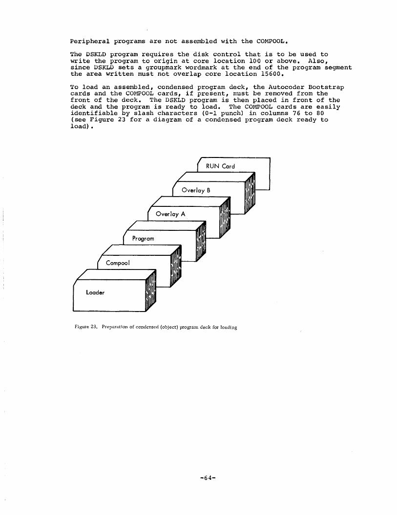
Peripheral programs are not assembled with the COMPOOL.
The DSKLD program requires the disk control that is to be used to write the program to origin at core location 100 or above. Also, since DSKLD sets a groupmark wordmark at the end of the program segment the area written must not overlap core location 15600.
To load an assembled, condensed program deck, the Autocoder Bootstrap cards and the COMPOOL cards, if present, must be removed from the front of the deck. The DSKLD program is then placed in front of the deck and the program is ready to load. The COMPOOL cards are easily identifiable by slash characters (0-1 punch) in columns 76 to 80 (see Figure 23 for a diagram of a condensed program deck ready to load) •
RUN Card
loader
Figure 23. Preparation of condensed (object) program deck for loading
-64-

WRITING PERIPHERAL PROGRAMS
Peripheral programs are called from the disk into core storage by a specific request from the console operator through terminal O. Communication to peripheral programs is through sense switches, as they have no communication with any terminal.
A peripheral program operates as part of the Scheduler. Thus; it may get control whenever the Scheduler is entered because of a 1448 interrupt or application program disk activity.
The ATS program is very time-sensitive. If the multiplexor needs service within 50 milliseconds and a peripheral program reads a card (requiring 75 milliseconds), characters in the 1448 buffer will be lost. Also, if the peripheral program uses all the time between multiplexor scans, there will be no time available for the application programs, and terminal requests will be processed too slowly.
Two tYPE~S of entries are provided for peripheral programs, depending on the 1time requirements of the program. One entry will give control to the peripheral program at every multiplexor scan. This entry is used by programs that require 50 milliseconds or less. An example of this type of peripheral program would be a tape-to-printer program that reclds tape records (preferably blocked) and writes single lines to the printer. This timing is why the Print Storage feature is required for all online printer operations. The second peripheral program entry gives control to the program whenever 100 milliseconds are available. A program reading cards for acard-to-tape operation is an e~cample of a peripheral program requiring the second type of entry.
A peripheral program is given control as soon as it is read from the disk. The console operator, however, will usually call the program into core befo:ce setting the sense swi tch communications. Thus, the program may find the sense switches set, in the process of being set, or not set at all. The peripheral program should check the sense switches on every entry, and, if they are incorrect or inconsistent, it should immediately return control to the Scheduler. Sense switches may be used to indicate to the program if output devices are ready. One sense switch may be used as an actuator, such that the program will take no action until it is set ON.
For ex~\ple, in a tape-to-printer operation, the operator will call the program into core, ready the required devices, and then set the sense switches~ Sense switches are also used to express variable conditions. For example, a switch may be set to indicate whether a tape is in even or odd parity. The sense switches available to peripheral programs are D, E, F, and G. Switches A, B, and Care reserved for the main system. ATS is operated with the I/O Check Stop Switch OFF. Card reader and printer errors will not cause the processor to halt, but will set an error latch that may be tested by various branch-·on-indicator instructions. The program should make every possible test to be certain that a peripheral device is ready before using it. It is quite possible for a peripheral program to be entel:ed often enough to exceed printer speed. Thus, the Printer Busy indicator should always be checked. If an error or busy condition is detected, return to the Scheduler should be immediate.
The return from a peripheral program to the Scheduler is to the instruct~ion following the branch to the p(eripheral program. -Because this address may change with different assemblies of the system, the peripheral program must save the return address with a Store B Register instruct:ion. This sequence might appear as follows:
-65-

CARTA SBR CA50+3 SAVE RETURN ADDRESS
Body of Program
CA50 B o RETURN TO SCHEDULER
Disk Dump (DSKDM) is a peripheral program provided as a standard feature with every ATS (see IBM l440~1460 Administrative Terminal System, Console Operator's Manual (H 6-6227), for a program description and operat~ng ~nstructions). In addition to the dump function, DSKDM contains a table with the identification and parameters for every peripheral program in the system. The MISAC program reads this table into the peripheral overlay area whenever the console operator requests a peripheral program. The table is checked to see if the program exists, where it is located on the disk, and what its communication parameters are. The peripheral program is then read into the proper area of core and communication with the Scheduler set. The peripheral program then gets control on the next mUltiplexor scan. Entries'in the peripheral table should be made in the DSKDM symbolic progralm, and that program should then be reassembled. The point for including these entries is marked clearly in the program listing.
A peripheral program table entry in DSKDM consists of five fields for every program. The first is the five-letter name of the program in SELECTRIC code. This entry is checked by MISAC to identify the program by comparing it with the console operator's request. The second field is the disk address of the program. This is a four-position literal, with a high-order zero understood. The third field is the number of sectors required by the program. This is a two-position literal. The fourth field is the core address of the beginning of the program. This address constant determines both where the program will be read into core and where the Scheduler will branch. The program must begin with the first instruction at this address. The final field is the type of Scheduler entry required by the peripheral program. This is a one-position literal. It is set to 1 if entry is desired on every scan, or 2 if entry is to be made only when 100 milliseconds are available, or 3 if entry is to be made in both instances. The source program for an entry in the table for a program called Model Pe:ripheral Program (MDLPP) might appear as follows:
DCW @JUYDD@
DCW @2035@
DCW @l5@
DCW +PERIPH
DCW @2@
DCW @:t: @
Name of program in SELECTRIC code
Disk address of program, high-order zero understood
Number of sectors used by the program
Core address of beginning of program
Scheduler entry type -- to be entered when 100 ms are available
A record mark follows the last entry signifying the end of the table
The fifth parameter is set in the MODE indicator in the System Status Table and is checked by the Scheduler before control is given to the peripheral program. Peripheral programs are loaded to the disk using the DSKLD program like application programs.
It should be noted that any peripheral program will degrade system response. Whether or not this degradation is tolerable can be learned
-66-
only by experience. Tape blocking is usually a critical factor in this rHgard. If possible, tape-to-printer operations should always use blocked tape. Blocked tape will eliminate time-consuming tape operations on every entry of the program.
WRITING APPLICATION PROGRAMS
Coding Practi~
The fil:st instruction of an application program is always labeled with the five·-character mnemonic of the name of the routine. This instruction will always be an unconditional branch to the start of the program. Following this branch, three DeW statements appear. For example, -the ATTEN program begins:
ATTEN B ATll DCW @OO@
ATIO DCW #2 DCW #3
The first DCW is used to designate the modification level of the prog~am. The second will receive the number of the terminal requesting serV~CE!. The third is used by the Scheduler for temporary storage and sl10uld never be used by the program.
The terminal number (which will be located at ATIO in the above example) is multiplied by ten and is then used to reference the proper entry in the MST. (There are ten characters per entry in the table.)
This tE~rminal number is usually used in index register 1. The instructions to load the index register are:
MLC @O@,Xl MLC ATIO
Reference to the running address, for example, is then:
MLC RUNA+Xl,TEMP
It will be found that coding can be reduced by letting index register 1 equal ten times the terminal number and index register 3 equal the address of the first position of the core block being worked with. Since this is the scheme used by the system subroutines, following the same convEantion will save the code necessary to set subroutine paramet:ers. Input/output with the disk file must be accomplished through IOCNX.. It is well to remember that index registers are not saved by IOCNX. 'They must be saved before giving control to that subrou't::ine if they are important to a program. The overlays of a program must be read in by the program itself, as the Scheduler will read only 20 sectors into the overlay area.
Locat!£lg the Attention Line
When an application program is read into core and executed, the only parameter conveyed from the Scheduler is the terminal number. This number will b,a located in the seventh and eighth positions of the program as described above. The program must determine what is requested by scanning the Attention line. The Attention line is found
-67-
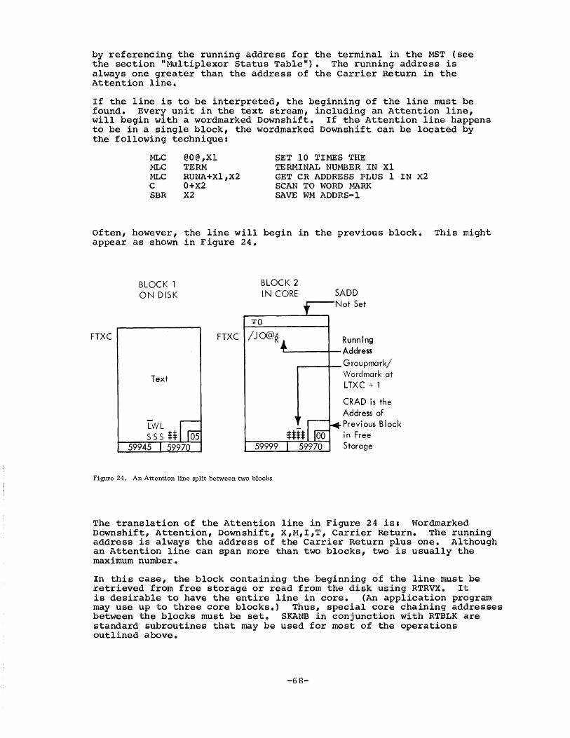
by referencing the running address for the terminal in the MST (se1e the section "Multiplexor Status Table"). The running address is always one greater than the address of the Carrier Return in the Attention line.
If the line is to be interpreted, the beginning of the line must be found. Every unit in the text stream, including an Attention line, will begin with a wordmarked Downshift. If the Attention line happens to be in a single block, the wordmarked Downshift can be located by the following technique:
f.'ILC f.'ILC MLC C SBR
@O@,Xl TERM RUNA+Xl,X2 0+X2 X2
SET 10 TIMES THE TERMINAL NUMBER IN Xl GET CR ADDRESS PLUS 1 IN X2 SCAN TO WORD MARK SAVE WM ADDRS-l
Often, however, the line will begin in the previous block. This might appear as shown in Figure 24.
FTXC
BLOCK 1 ON DISK
Text
BLOCK 2 IN CORE SADD
....... --Not Set
FTXC /JOOR
59999
Running L..----I--Address
~_--I_ Groupmark/ Wordmark at LTXC + 1
CRAD is the Address of Previ ous Block in Free Storage
Figure 24. An Attention line split between two blocks
The translation of the Attention line in Figure 24 is: Wordmarked Downshift, Attention, Downshift, X,M,I,T, Carrier Return. The running address is always the address of the Carrier Return plus one. Although an Attention line can span more than two blocks, two is usually the maximum number.
In this case, the block containing the beginning of the line must be retrieved from free storage or read from the disk using RTRVX. It. is desirable to have the entire line in core. (An application program may use up to three core blocks.) Thus, special core chaining addresses between the blocks must be set. SKANB in conjunction with RTBLK are standard subroutines that may be used for most of the operations outlined above.
-68-
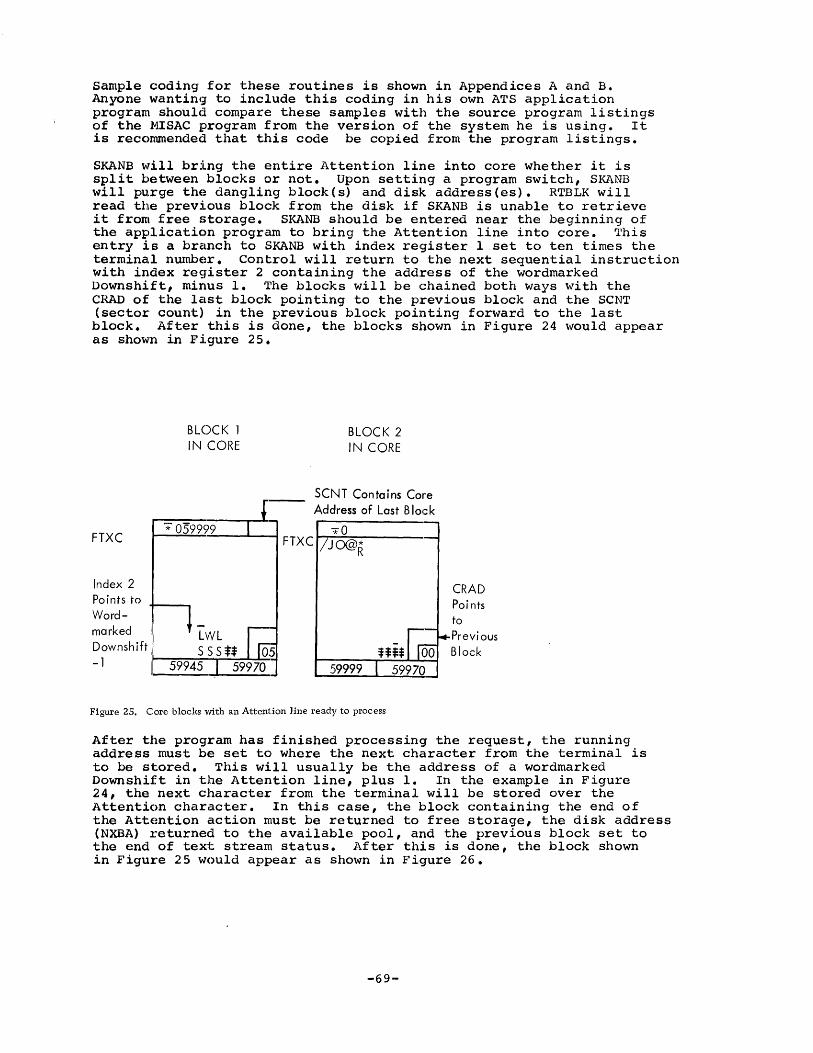
Sample coding for these routines is shown in Appendices A and B. Anyone wanting to include this coding in his own ATS application program should compare these samples with the source program listings of the MISAC program from the version of the system he is using. It is reccmunended that this code be copied from the program listings.
SKANB ~Till bring the entire Attention line into core whether it is split between blocks or not. Upon setting a program switch, SKANB will purge thE~ dangling block (s) and disk address (es) • RTBLK will read the previous block from the disk if SKANB is unable to retrieve it front free storage. SKANB should be entered near the beginning of the application program to bring the Attention line into core. This entry is a branch to SKANB with index register 1 set to ten times the termina.l number. Con'trol will return to the next sequential instruction with index register 2 containing the address of the wordmarked Downshift, minus 1. The blocks will be chained both ways with the CRAD of the l~Lst block pointing to the previous block and the SCNT (sector count) in the previous block pointing forward to the last block. After this is done, the blocks shown in Figure 24 would appear as shown in Figure 25.
FTXC
Index 2 Po ints to Wordmarked Downshift -1
BLOCK 1 IN CORE
-.;; 059999
BLOCK 2 IN CORE
SCNT Contains Core Address of Last Block
*0 FTXC /JO@R
59999
Figure 25. Core blocks with an Attention line ready to process
CRAD Poi nts to Previous Block
After the program has finished processing the request, the running address must be set to where the next character from the terminal is to be s1~ored. This will usually be the address of a wordmarked Downshift in the Attention line, plus 1. In the example in Figure 24, the next character from the terminal will be stored over the Attention character. In this case, the block containing the end of the AttE~ntion action must be returned to free storage, the disk address (NXBA) returned to the available pool, and the previous block set to the end of text stream status. After this is done, the block shown in Figure 25 would appear as shown in Figure 26.
-69-

New Running Address
FTXC
Groupmark/ Wordmark at LTXC + 1
Text Stream Ended
BLOCK 1 IN CORE
* 059999001
Text
With NXBA Equal SADD
BLOCK 2 TO FREE STORAGE
*0
FTXC /JO@R
Disk Address to Available Pool
Figure 26. Core blocks after processing an Attention line
The SKANB subroutine may be used to accomplish this by setting wordmarks on the program switches at SK16+4 and SK17+4. The~e switches are of the form:
SK16 BIN SK17,{ BRANCH TO PURGE CORE BLOCKS
This instruction normally appears only in Field Engineering diagnostic programs. It is a branch on parity error if the Check Stop Switch is OFF. Since ATS always runs with the Check Stop Switch ON, the instruction is normally a NOP. If a wordmark is set on the D character, the instruction becomes an unconditional branch. To purge the dangling block, this entry sequence should be used:
MLC @O@,Xl MLC TERM SW SK16+4,SK17+4 B SKANB
SET TEN TIMES TERMINAL NUMBER TO Xl SET SWITCHES FOR PURGE PURGE DANGLING BLOCKS
Return is to the next sequential instruction with the dangling block and disk address purged. The NXBA of the previous block points to itself, thus ending the text stream. Index register 2 contains the address of the wordmarked Downshift, minus 1. The wordmark on 1:he groupmark at LTXC+l is not set, however, and must be set by the main program.
WARNING: The line must have beep brought into core previously by a branch to SKANB without these switches set before attempting to purge dangling blocks by a second entry to SKANB with the switches set.
In some applications, it is desirable to keep the Attention line in the text stream. In these cases, the previous core blocks must be returned to the free storage chain. The contents of the blocks are also safely on the disk. The next characters keyed by the terminal
-70-

will enter the block following the last line. The application program is responsible for setting the status for the new line. Thus, a wordmal~ked Downshift is inserted following the Carrier Return character. 'l'he LCIB field in the last block and the Line field in the TST must be incremented by one. If the text is in the Automatic Mode, the Carrier Return on the Attention line must be wordmarked. Examples of this type of Attention line are the requests for the Automatic and Uncontrolled Modes. This type of Attention line may also be split between two blocks. This might appear as shown in Figure 27.
BLOCK 1 BLOCK 2 ON DISK IN CORE at 59999 SADD *0
PR t Not Set FTXC FTXC
Running Text Address
59999
FigUl'e 27. A request for Automatic Mode split between two blocks
BLOCK 1 IN CORE TO FREE STORAGE
r=~----------~ *0
59945 I 59970
*0
BLOCK 2 IN CORE
SADD Not Set
--------f- Runni ng Address
59999
FigUl'e 28. Core bloeks after processing a retained Attention line
-71-
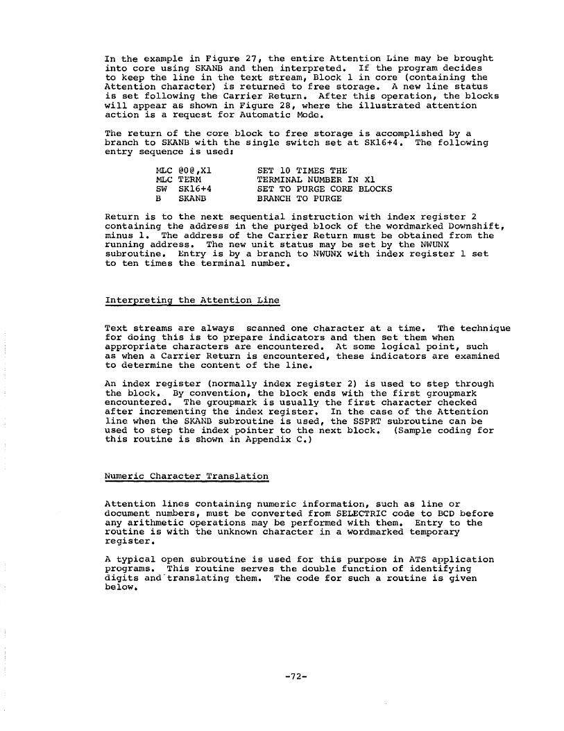
In the example in Figure 27, the entire Attention Line may be brought into core using SKANB and then interpreted. If the program decides to keep the line in the text stream, Block 1 in core (containing the Attention character) is returned to free storage. A new line status is set following the Carrier Return. After this operation, the blocks will appear as shown in Figure 28, where the illustrated attention action is a request for Automatic Mode.
The return of the core block to free storage is accomplished by a branch to SKANB with the single switch set at SKl6+4. The following entry sequence is used:
MLC @O@,Xl MLC TERM SW SK16+4 B SKANB
SET 10 TIMES THE TERMINAL NUMBER IN Xl SET TO PURGE CORE BLOCKS BRANCH TO PURGE
Return is to the next sequential instruction with index registel~ 2 containing the address in the purged block of the wordmarked Downshift, minus 1. The address of the Carrier Return must be obtained from the running address. The new unit status may be set by the NWUNX subroutine. Entry is by a branch to NWUNX with index register ]. set to ten times the terminal number.
Interpreting the Attention Line
Text streams are always scanned one character at a time. The 1:echnique for doing this is to prepare indicators and then set them when appropriate characters are encountered. At some logical point, such as when a Carrier Return is encountered, these indicators are examined to determine the content of the line.
An index register (normally index register 2) is used to step through the block. By convention, the block ends with the first groupmark encountered. The groupmark is usually the first character checked after incrementing the index register. In the case of the Attention line when the SKANB subroutine is used, the SSPRT subroutine can be used to step the index pointer to the next block. (Sample coding for this routine is shown in Appendix C.)
Numeric Character Translation
Attention lines containing numeric information, such as line or document numbers, must be converted from SELECTRIC code to BCD before any arithmetic operations may be performed with them. Entry to the routine is with the unknown character in a wordmarked tempora~ register.
A typical open subroutine is used for this purpose in ATS application programs. This routine serves the double function of identifying digits and'translating them. The code for such a routine is given below.
-72-

*LITERALS REQUIRED FOR OPERATION
TEMP BFER
TRAN TRTB RAWD
* MP19
MP20
*
MP30 MP3l MP32 MP33
DCW =1 EQU *+1 DCW =5 DCW -MP20+7 DCW @Y9=7564832l@ DCW =3 --_ ...... _----
BEGIN TRANSLATE ROUTINE SBR X3,BFER
-----------MLC TEMP ,MP20+7 BCE MP30,TRTB,* BCE BCE BCE BCE BCE BCE BeE BCE BCE BCE
HOLDS UNKNOWN CHARACTER HOLDS TRANSLATED CHARACTERS
'l'RANSLATE AD CON TRANSLATE LITERAL DATA AREA FOR TRANSLATION
SET POINTER TO BFER START
MOVE CHAR 'fO BCE D CHAR BRANCH IF A .l BRANCH IF A 2 BRANCH IF A 3 BRANCH IF A 4 BRANCH IF A 5 BRANCH IF A 6 BRANCH IF A 7 BRANCH IF A 8 BRANCH IF A 9 BRANCH IF A 0 BRANCH IF AN L
(FELL THROUGH, NOT A DIGIT)
SBR MA MN SBR B
RAWD TRAN,RAWD RAWD,0+X3 X3,1+X3 MPIO
SAVE BCE ADDR+l SUBTRACT BASIC ADDRESS GET TRANSLATION TO BFER INCREMENT POINTER BRANCH TO MAIN LINE
*
*
*
The Store B Register instruction will store the three-position number or address in the B Address Register into the three-position field addressed by the A field of the instruction. The machine reads the entire instruction before executing it. Thus, in the case of the SBR at MP19 in the coding above, the B Address Register will be set by the B field of the instruction itself. After execution of this instruction, index register 3 will contain the machine address of BFER, the high-order address of a five-character field. The machine performs indexing before execution. This is used to advantage in the SBR instruction at MP33 in the coding above. In this case, the contents of index register 3, incremented by 1, will be stored back into index register 3.. When the processor executes a branch instruction, the address of the next sequential instruction is forced into the B Address Register. A four-character SBR instruction, such as the one at MP30 in the coding above, will save this address in the location indicated by the A field of the instruction.
The TRTB (Translate Table) literal contains all the numeric codes generated by the terminals in ascending order from right to left. The TRAN address constant is assembled as the l6,000's complement of the address of the D character at MP20. RAWD is the work area where the translation is performed.
The Branch Character Equal instructions, beginning with MP20, step through the Translate Table. Full chained BCE instructions leave the A Address Register unaltered but decrement the B Address Register. Thus, the branch address remains MP30, but the TRIB literal is stepped through. The D character is unaffected by this operation. If any BCE causes a branch, the address of the next sequential instruction
-73-
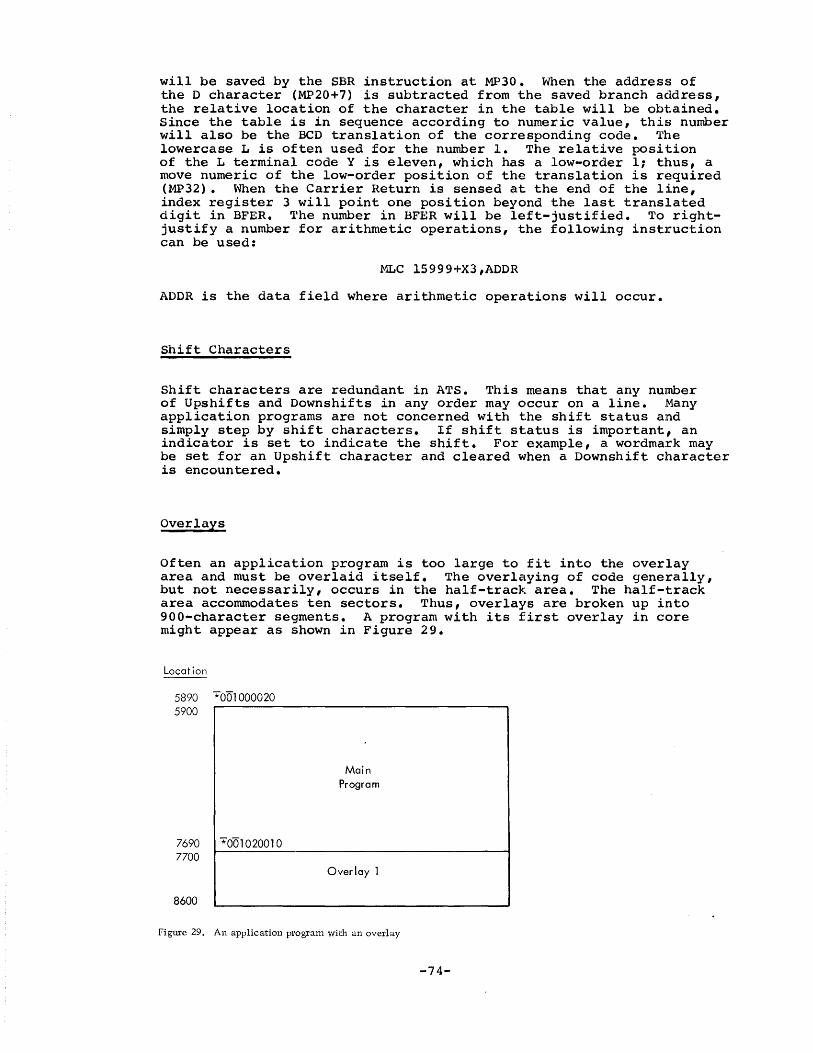
will be saved by the SBR instruction at MP30. When the address of the D character (MP20+7) is subtracted from the saved branch address, the relative location of the character in the table will be obt:ained. Since the table is in sequence according to numeric value, this number will also be the BCD translation of the corresponding code. 'l'he lowercase L is often used for the number 1. The relative position of the L terminal code Y is eleven, which has a low-order 1; thus, a move numeric of the low-order position of the translation is required (MP32). When the Carrier Return is sensed at the end of the line, index register 3 will point one position beyond the last translated digit in BFER. The number in BFER will be left-justified. To rightjustify a number for arithmetic operations, the following instruction can be used:
MLC l5999+X3,ADDR
ADDR is the data field where arithmetic operations will occur.
Shift Characters
Shift characters are redundant in ATS. This means that any number of Upshifts and Downshifts in any order may occur on a line. Many application programs are not concerned with the shift status and simply step by shift characters. If shift status is important, an indicator is set to indicate the shift. For example, a wordmark may be set for an Upshift character and cleared when a Downshift character is encountered.
Overlays
Often an application program is too large to fit into the overlay area and must be overlaid itself. The overlaying of code generally, but not necessarily, occurs in the half-track area. The half-track area accommodates ten sectors. Thus, overlays are broken up into 900-character segments. A program with its first overlay in core might appear as shown in Figure 29.
Locat ion
5890 *0'01000020 5900
7690 *0'01020010 7700
8600
Main Program
Overlay 1
Figure 29. An application progTam with an overlay
-74-

The disk addrE~ss of the overlay will always be the address of the main program plus an increment. The disk control field that was used to read the main program in will be in correct form immediately preceding the overlay area at core position 5890. Since an application program is 20 sectors long by definition, the first overlay will be located 20 sectors beyond the disk address of the main program. As overlays are ten sectors long, the second overlay will be ten sectors beyond the first overlay. Thus, if the main program is located at sector address 1000, the first overlay will be at sector address 1020, the sec:ond oVHrlay at address 1030, and so on. It is a good programming practice to c()nstruct disk control fields rather than to use absolute addrese;es. This technique makes it possible to relocate a program on the disk without being forced to alter the code. Sample coding for a subroutine to read overlays is found in Appendix D.
Communication between overlays may be accomplished by branching to a communication table. A sample of such a communication table is found in Appendix Eo
Special. ~ssag~
Special. messages generated by application programs are always transmitted from a core block. Usually these messages will be less than 75 charac:ters long and will fit into a single block. There is no guar'antee that there will be room for the message in the last text block. If there is not room in this block, the last block should be written to the disk and a new block attached to the end of the chain as explained below. ~rhe amount of room remaining in the block can be foun.d by examining the two low-order numeric positions of the address of the wordmarked Downshift of the last line. If the SKANB subroutine is used to purge dangling blocks, the numeric address of the wordmarked Downshift, minus 1, will be found in SK22. The message should begin immediately following the wordmarked Downshift of the last line and end with a record mark followed by a 2 or a 3. The running address and the saved running address for the terminal are set to the address of the beginning of the message, and the line status in the MST is set to Transmit. At this point, the application pr0gram has finished its processing and branches to FINIY., followed by the appropriate exit address constant,. The message will be transmitted to the point of the record mark. The Scheduler, sensing the 2 or 3 following the record mark, will move the saved running address to the runnin9 address and set the status character to ReceiveIdle. The next characte~ keyed from the terminal will be stored over the message.
In the case where there is no room in the last block for the message, there are two methods for adding a new block. One method is to move a group:mark (ending the block) on top of the wordmarked Downshift of the last line, and to clear the wordmarko This will end that block. Since one less line will now occupy the block, the LCIB must be decremented by one. This may be accomplished by a modify address instruction:
MA @I9I@,LCIB+X2
-75-

BLOCK IN CORE AT TIME OF PROGRAM ENTRY
SADD Not Set
"* 0
FTXC
Text Running ,--------t-Address
LWL/* S S S R
59987
BLOCKS AFTER PROGRAM COMPLETE--METHOD 1 On Disk at 59765
$ WL/* SS R
59987
Text
FTXC Running a Saved Running Addresses
nd
LC IB LCIB Eq ual 1 Decremented
BLOCKS AFTER PROGRAM COMPLETE--METHOD 2 On Disk at 59765
Text
FTXC
In Core
-;0
1. Message t 3
S t
$tlrl roT 59765 I 59999
In Core
*0 Message :f:3 j
Running Address and Saved Running Address Equal FTXC
-I-
I ******!*!*!*
**ll****lt**f ros= 59987 I 59999
Figure 30. Methods for adding a block for message transmission
-76-
****1 fOo 59765 I 59999
A new core block is obtained from free storage with NCBKX. THE NXBA of the last block is loaded into the SADD of the last block and the LSBA of the new block. A new disk address must be obtained via NDBKX to go into the NXBA of both blocks. The old block is now ready to be writ,ten to the disk. A wordmarked Downshift is loaded into FTXC' of the new block and the LCIB set to 1. The Early Harning groupmarks must be: set, including a groupmark/wordmark at LTXC+l. Sample coding for a subroutine (from the BLKOP program) that chains Working Storage to anot,her blc)ck may be found in Appendix F.
The sec:ond tec:hnique .is to leave the wordmarked Downshift in the last block. In this case, LCIB is not altered, and the LCIB in the new block is not set to 1. However, from ~TXC+l back to th~ character following the wordmarked Downshift, the ,first block must be set to a contiguous series of groupmarks. These ,two techniques are illustrated in Figure 30.
output Text Streams
Output streams and messages exceeding one block constitute a programgenerated text stream. The procedure for generating an output text stream is to ·write out the last text block, saving the five-character disk address in the LLDA field in the First Block (FBK). The text stream is then generated. The LCIB and CRAD indicators are not important. W()rdmarks may appear anywhere in the text and will not affect transmission. The text in each block, except for the last block, must begin at FTXC and end with a record mark follo~ed by a groupmark. The last block be'gins at FTXC and ends with a record mark followed by a 6. ' After the stream has been generated, the first Transmit block is read into core, the running address set to FTXC, and the status set to Transmit. There must be no other blocks pertaining to the terminal in core except the beginning Transmit block. The application program now exits. The Scheduler keeps 'the text flowing to the terminal until the record mark followed by a 6 is encountered. At this time, the MISAC program is called into core. MISAC obtains the address of the last text block from the LLDA field in the First Block (FBK) and sets the line status for the terminal to Recedve-Idle.
Priority Inte:crupt
Programs with low priority and requiring long periods of processing must bE~ able ·to relinquish the overlay area to programs of higher priority. The procedure for doing this begins by saving important pointers and indicators. This may be done in a core block1 in the first block (FBK); in the TSLS, TSNS, or LLDA fields1 or in a Working Storage block on the disk. If fields in the first block are used, they must be blanked before the final exit from the application program. Wordmarks may not be left in unexpected locations. At the time oj: program exit, only one block pertaining to the terminal may be in c;:ore.
The program relinquishing the overlay area sets a New Job entry for itself via SNJBX. The entry parameters are index register 1 set to ten times the terminal number, and index register 2 set to the PST number of the program. The NJB entry will be sorted into it's priority level in the NJB queue. It is possible that there are already several requests in the NJB queue for the interrupting program. In this case, the entry will be sorted to the top of all entries for the program.
-77-
In cases where it is desirable to circulate through all pending requests for one program, the PROV indicator in the System Status Table should be blanked before branching to SNJBX. The New Job entry will then be sorted to the bottom of the requests for the program. This latter technique will process short requests faster than l()nger requests.
The NJB queue is checked by moving the NJB pointer to an index register and checking the top program in the queue.
CAUTION: The pointer must be checked to see if it is blank. ThE~ coding to accomplish this might be:
*
BCE EX25,NJPT, MCW NJPT,X3 C 6+X3,PSTN
BL EX25
Interrupt Routine
PSTN DCW +PPROGM
BRANCH IF BLANK POINTER GET NJB LOCATION DOES PROGRAM HAVE HIGHER PRIORITY
NO, CONTINUE
PST NUMBER OF PROGRAM
The interrupting program must be able to distinguish between a new task and a partially completed task. To accomplish this, an indicator is set in core. Usually, the PACT indicator (numeric) in the MST is set to 9. -,::ne'n the program is entered, it checks this character. If it is a 9, the program locates the status of a task in progress that it saved and continues processing. The P,ACT entry must be cleared before the final exit of the program. When the status character is set to Control, the MST entry is not altered by the multiplexor or any other program.
SYSTEM OUTPUT FORMATS
Some users of 1440/1460 ATS may wish to use the various possiblE! system outputs as input to further computer processing. This section lists briefly the formats of all magnetic tape records that can be produced by ATS and that may be of interest for further processing.
Permanent Storage Tape
The Permanent Storage Tape consists of Permanent Storage half-track records read from the disk and written to tape in the Load mode with even parity. These records are 900 characters in length with a tapemark following the last record. ~he 900 characters on tape are identical to the 900 characters on disk with one exception: the Attention character (word separator) cannot be saved on tape in the Load mode and in order to preserve this character, it is translated to a segment mark. When ATS reads the tape, all segment marks are converted back to Attention characters.
For a detailed description of the record format, see the "Permanent Storage Tape" section of this manual. The text contained in these records is in Terminal Code with all of the ATS text stream conventions observed.
-78-

Card Image Tape
This tape is produced when a document is transmitted to terminal 97. It consists of 80-character records writ·t.en in the Move mode with even pa.ri ty. Tapemarks are not generated automatically but must. be entered by thel originating terminal. Th.is is accomplished by typing a tapemark using the ATS mUltipunch feature (7 BKSP 8) in column 1 of the appropriate card.
The car'd images are an exact duplicate of the originating terminal's input a.s it appears l2.rinted on the terminal, one line per card. Beginning at the left-hand margin, every character position on the termina.l reprElsents a card column in the final output. Tab stops are set in character positions representing the beginning of data fields. These tab stop settings are associated with a special Heading mode request. (See the section "Keypunching" in IBM 1440/1460 ATS, Terminal o~erato~ ~~ (H20-0l85) for further informat~on.) ---
Print with Line Numbers Tape
This tape is produced when a document is transmitted to terminal 98 and Sense Switch B is ON (up). It consists of l33-character print line image records, with a blank carriage control code in the first position, written in Move mode with even parity. A carriage control code of "1" is used in the first record of each document. A tapemark is written aft.er each document, and two tapemarks after all documents have been written on tape.
The pri.ntout is similar to the ATTN pnO printou":. at the terminal with the following exceptions: All alphabetic characters are uppercase: special characters, such as colons and brackets, do not print, the line or unit number is located at the left-hand margin, all line or unit numbers are printed.
Upper-_and Lowercase Chain Print Tape
This tape is produced when a document is transmitted to terminal 96 and Sense Switch B is ON (up). The tape is written in the Load mode in even parity with a tapemark following the last record. The records may be either 133 or 15 characters long. In either case the first character of the record is a carriage control character:
Control Character - Slank
J K L 1 + A
Meanin2 SIngle-space after printing Immediate one-space skip Immediate two-space skip Immediate three-space skip Page eject Print and suppress space Eject page after printing
The l33-character records contain formatted print images with a carriage control character. The l5-character records contain only the carriage control character. The last record, and only the last record.; of each document will always contain the carriage control charact~er A.
-79-

This printout is formatted according to the last printout requested by the originating terminal. Page width and depth are also the same as the settings for the originating terminal. The Courier typehead is assumed, which means that brackets (not + and 1) are considered the standard characters. (For information on the way of entering characters that do not appear on the Courier 72 typehead, see the section "Upper- and Lowercase Chain Output" in IBM 1440(1460 ATS, Terminal Operator's Manual (H20-0l85).) --- ---
Underscored and other overstruck character positions will be written as multiple records, all except the last of which will have a control character of "+".
Almost all 7-bit (including wordmark) character combinations are different characters on this tape. A complete listing of the characters available follows.
Chain Position
1 2 3 4 5 6 7 8 9
10 11 12 13 14 15 16 17 18 19 20 21 22 23 24 25 26 27 28
29 30
31 32 33 34 35 36 37
1440(1460 ATS SUPPORT OF l20-CHARACTER COURIER PRINT CHAIN (Part 823380)
Chain BCD Load Mode Character Gral2hic ~ Card Code
Numeral One 1 1 1 1 Numeral Two 2 2 2 2 Numeral Three 3 21 3 3 Numeral Four 4 4 4 4 Numeral Five 5 4 1 5 5 Numeral Six 6 42 6 6 Numeral Seven 7 421 7 7 Numeral Eight 8 8 8 8 Numeral Nine 9 8 1 9 9 Numeral Zero 0 8 2 0 0 Equal = 8 21 3-8 Apostrophe 84 4-8 Greater Than > 84 1 1-4-8 ) Less Than < 842 2-4-8 ( Plus + BA 12 + Slash ( A 1 0-1 ( Lowercase s s A 2 0-2 s Lowercase t t A 21 0-3 t Lowercase u u A 4 0-4 u Lowercase v v A 4 1 0-5 v Lowercase w w A 42 0-6 w Lowercase x x A 421 0-7 x Lowercase y y A8 0-8 Y Lowercase z z A8 1 0-9 z Up arrow l' A8 2 0-2-8 @ Comma A8 21 0-3-8 Left Paren. A84 0-4-8 Hinus
(or Hyphen) - B 11 Vertical Line A842 0-6-8 ( Lower Left L
Corner A8421 0-7-8 Lowercase j j B 1 11-1 j Lowercase k k B 2 11-2 k Lowercase 1 1 B 21 11-3 1 Lowercase m m B 4 11-4 m Lowercase n n B 4 1 11-5 n Lowercase 0 0 B 42 11-6 0
Lowercase p p B 421 11-7 P
-80-
Terminal Courier Rel2resenta'tion
BKSP 0
BKSP 0
BKSP 0
BKSP *
BKSP 0
BKSP *
72

Chain Chain BCD Load Mode Terminal Courier 72 Posi tioE, ~~ Gra12hic ~ ~d Code ReJ2resentation
38 Lowercase q q B 8 11-8 q 39 Lowercase r r B 8 1 11-9 r 40 Excl.amation
Point ! B 8 2 11-0 ! 41 Doll.ar Sign $ B 8 21 11-3-8 $ 42 Asterisk * B 84 11-4-8 * 43 Lower Right
Corner .J B 84 1 11-5-8 BKSP * 44 Upper Left
Cc)rner r B 842 11-6-8 BKSP , 45 Upper Right
Corner ., B 8421 11-7-8 BKSP , 46 LOWE~rcase a a BA 1 12-1 a 47 Lowercase b b BA 2 12-2 b 48 LOWE!rCaSe c c BA 21 12-3 c 49 Lowercase d d BA 4 12-4 d 50 Lowercase e e BA 4 1 12-5 e 51 Lowercase f f BA 42 12-6 f 52 Lowercase g g BA 421 12-7 g 53 Lowercase h h BA8 12-8 h 54 Lowercase i i BA8 1 12-9 i 55 Horizontal
Line BA8 2 12-0 - BKSP 0 (or 0 BKSP-) 56 Period BA8 21 12-3-8 57 Right
Parenthesis ) BA84 12-4-8 58 Cro~;sed Lines + BA84 1 12-5-8 + BKSP 0
59 Right Bracklet ] BA842 12-6-8 ] 60 Lef1: Bracket t 8421 7-8 [ 61 SupE~rscript
One w 1 0-5-8/1 1 BKSP * 62 SupE!rscript 2
Two w 2 0-5-8/2 2 BKSP * 63 SupE!rscript 3
Three w 21 0-5-8/3 3 BKSP * 64 SupE!rscript 4
Four w 4 0-5-8/4 4 BKSP * 65 SupE!rscript 5
Five w 4 1 0-5-8/5 5 BKSP * 66 SupE!rscript 6
Six w 42 0-5-8/6 6 BKSP * 67 SupE!rscript 7
SE!Ven w 421 0-5-8/7 7 BKSP * 68 SupE!rscript 8
Eight w 8 0-5-8/8 8 BKSP * 69 SupE!rscript 9
Nine w 8 1 0-5-8/9 9 BKSP * 70 Superscript 0
ZE~ro tJ 8 2 0-5-8/0 0 or 0 BKSP * 71 Number Sign # w 8 21 0-5-8/3-8 # 72 Quotation
Mark " w 84 0-5-8/4-8 " 73 Greater Than ~
or Equal w 84 1 0-5-8/5-8 BKSP = 74 Less Than s:
or Equal w 842 0-5-8/6-8 BKSP = 75 Ampersand & wBA 0-5-8/12 & 76 Backward Slash" w A 1 0-5-8/0-1 / BKSP -77 Uppercase S S w A 2 0-5-8/0-2 S 78 UppE3rcase T T w A 21 0-5-8/0-3 T 79 Uppercase U U w A 4 0-5-8/0-4 U 80 Uppercase V V wA 4 1 0-5-8/0-5 V
-81-

Chain position
81 82 83 84 85 86 87 88 89 90 91 92 93 94 95 96 97 98 99
100 101 102 103 104 105 106 107 108 109 110 111 112 113 114 115 116 117 118 119 120
Character Chain
Graphic BCD Load Mode ~ Card Code
Uppercase W W Uppercase X X Uppercase Y Y Uppercase Z Z Left Arrow ~ Semicolon ; Percent Sign % High Hyphen At Sign @ Logical And A Uppercase J J Uppercase K K Uppercase L L Uppercase M M Uppercase N N Uppercase 0 0 Uppercase P P Uppercase Q Q Uppercase R R Question Mark ? Underscore Subscript One .r Subscript Two 2 Subscript Three 3 Subscript n Uppercase A A Uppercase B B Uppercase C C Uppercase D 0 Uppercase E E Uppercase F F Uppercase G G Uppercase H H Uppercase I I Plus or Minus ± Colon Bullet • Not Equal ~ Right Brace JLeft Brace .(
w A 42 w A 421 w A8 w A8 1 w A8 2 w A8 21 w A84 wB w A842 w A8421 wB 1 wB 2 wB 21 wB 4 wB 4 1 wB 42 wB 421 wB 8 wB 8 1 wB 8 2 wB 8 21 wB 84 wB 84 1 wB 842 wB 8421 wBA 1 wBA 2 wBA 21 wBA 4 wBA 4 1 wBA 42 wBA 421 wBA8 wBA8 1 wBA8 2 wBA8 21 wBA84 wBA84 1 wBA842 w 8421
0-5-8/0-6 0-5-8/0-7 0-5-8/0-8 0-5-8/0-9 0-5-8/0-2-8 0-5-8/0-3-8 0-5-8/0-4-8 0-5-8/11 0-5-8/0-6·-8 0-5-8/0-7-8 0-5-8/11-1 0-5-8/11-2 0-5-8/11-3 0-5-8/11-4 0-5-8/11-5 0-5-8/11-6 0-5-8/11-7 0-5-8/11-8 0-5-8/11-9 0-5-8/11-0 0-5-8/11-3-8 0-5-8/11-4-8 0-5-8/11-5-8 0-5-8/11-6-8 0-5-8/11-'"1-8 0-5-8/12-1 0-5-8/12-2 0-5-8/12-3 0-5-8/12-4 0-5-8/12-5 0-5-8/12-6 0-5-8/12-'"1 0-5-8/12-8 0-5-8/12-9 0-5-8/12-0 0-5-8/12-3-8 0-5-8/12-4-8 0-5-8/12-5-8 0-5-8/12-6-8 0-5-8/7-8
Storage Report Tape
Terminal Courier 72 Representation
W X Y Z @ BKSP -. , % - BKSP * or *BKSP -@ & BKSP , J K L M N o P Q R ?
r BKSP , 2 BKSP 3 BKSP n BKSP , A B C o E F G H I + BKSP = • BKSP 0
/ BKSP = ] BKSP -[ BKSP -
When a Storage Report is requested on tape, it will be written as 133-character print line image records in the Move mode with even parity. The first character will be a control code. This code is the same as the forms control character that would appear for the equivalent function in the D-modifier of the control carriage instruction. For example, the D-modifier for an immediate skip to Channell is the digit 1 and it is this number that would appear in the first position of the record. The normal carriage action is an immediate skip of one line aft"er printing, which is noted by the "/" (slash) character that normally appears in the first position of the record. The print tape is written with the same carriage control functions as would be used if the report appeared on the high-speed printer.
-82-

APPENDIX A: SAMPLE CODING FOF A SKANB SUBROUTINE
0299 ******************************************************************* 0300 * SKANb WIll SEARCH BACK FOR A WM-ED CHAR (STEPPING FROM BlOCK* 0301 * TO BLOCK AS REQUIRED) BEGINNING AT ONE lESS THAN THE TERMIN-* 0302 * Al-S RUNNING ADDRESS. AFTER THE SKANNED-OUT lINE HAS BEEN * 0303 * PROCESSED, THE PROGRAM MAY SET-WM ON SK16+4 (TO PURGE ANY * 0304 * DANGLING CORE BlKS) OR SK16+4 AND SK17+4 (TO PURGE ANY * 0305 * DANGLING DISK BlKS AS WEll AS CORE BLKS). ENTER WITH Xl EQ * 0306 * TO TEN TIMES THE TERMINAL NUMBER. EXIT WITH X2 EQ ONE lESS * 0307 * THAN THE WM-ED CHA~. Xl WIll BE PRESERVED. * 0308 ******************************************************************* 0309 SKANB SBR SK13+3 SAVE RETURN ADDRESS 0310 MCW RUNA+Xl,X2 GET TERMINALS RUNNING ADDRESS 0311 SBR X2,15999+X2 STEP IT TO lAST RECEIVED CHAR 0312 SK11 C 0+X2 SKAN BACK FOR A WM 0313 SBR X2 SAVE 1 lESS THAN WM-ED CHAR 0314 bCE SK14,X2-1,9 BRANCH IF OVERSHOT BLOCK 0315 MN X2,SK22 GET CHARACTER ADDR 0316 MN 0317 C SK21,SK22
SK15 SK16+4,SKI7+4
0318 Bl 0319 CW 0320 SK13
0321 SK14 0322 SK15 0323 0324 SK16 0325 0326 0327 0328 0329 0330 0331 0332 0333 SK17 0334 0~35 0336 0337
0338 0339 0340 SI<19 0341 0342 0343 0344 0345 03/+6 0347 0348 0349 S 1<21 0350 SI<22
KGO • R
SBR X2,1+X2 MN @00@,X2 MN bIN SK17,( MCW X2,X3 B RTRVX BCE SKll,96, B RTBlK MZ X2,CRAD+X3 MZ MCW B SKII BIN SK19, ( BCE SKI3,CRAD-2+X2, MCW CRAD+X2,X3 B HDFSX
Kl S
SBR X2,lTXC+X3 B SKll SBR X3,NXBA+X2 B PDBKX MZ CRAD+X2,X2 MZ MCW MCW SADD+X2·,NXBA+X2 B HDFSX SBR X2,lTXC+X2 b SKll DCW +FTXC-1 DCW =2
IS IT lOWER THAN FTXC-l YES. SKAN OVERSHOT VALID TEXT. CLEAR SWITCHES ENABLE INTERRUPTS AND RETURN
STEP TO ORIGINAL BLOCK CLEAR X2 CHAR ADDR
BRANCH TO PURGE CORE BLOCKS MOVE BlK ADDR TO X3 BRANCH FOR PREVIOUS BlK BRANCH IF BLOCK IN CORE bRANCH TO READ FROM DISK HSKP FORMER CRAD POINTER
BRANCH TO CONTINUE SKAN. BRANCH TO PURGE DISK BLOCKS TOO IF NO CRAD, DO NOT STEP FURTHER GET ADDR OF NXT CORE BlK BACK BRANCH TO PURGE IT DISABLE INTERRUPTS
SET X2 TO lTXC IN PURGED BLOCK BRANCH TO SKAN IT SET X3 TO A(NXBA/THIS BlK) BRANCH TO PURGE DISK AD DR GET ADDR OF NEXT BlK BACK
MOVE SADD OF THAT BlK TO NXBA PURGE CORE BlK SET X2 TO lTXC IN NEW BlK BRANCH TO SKAN IT USED TO DETECT BlK OVERSHOOT TEMP STORAGE FOR CHAR ADDR
-83-
MISAC MISAC MISAC MISAC MISAC MISAC MISAC MISAC MISAC MISAC MISAC MISAC MISAC MISAC MISAC MISAC MISAC MISAC MISAC MISAC MISAC MISAC
MISAC MISAC MISAC MISAC MISAC MISAC MISAC MISAC MISAC MISAC MISAC MISAC MISAC MISAC MISAC MISAC MISAC
MISAC MISAC MISAC MISAC MISAC MISAC' MISAC MISAC MISAC MISAC MISAC MISAC MISAC

APPENDIX B: SAMPLE CODING FOR A RTBLK SUBROUTINE
SBR MCW MCW MZ MZ MCW B DCW DCW DCW MCW SBR SBR SBR SBR I5CE H
RT53+3 X1,RT52+6 X2,RT49 X3,RT51+6
IOCNX =1 @l@ =3 RT49,X2 SCNT+X2,O X3 X2,LTXC+X2 X 1, ° O,RT48,
BRANCH TO READ BLK CONDITION COMMUNICATIUN READ, 1 BLK, LOW PRIORITY ADDRESS OF BLK (IOAR) MOVE BLK ADDR TO X2 SET SCNT TO NEXT BLK FWD IN CORE RESTORE X3 SET X2 TO LTXC IN BLK RESTORE Xl RETURN TO PROGRAM IF I/O OK HALT. CATASTROPHIC ERROR.
-84-
MISAC MISAC 111 I SAC MISAC MISAC MISAC MISAC MISAC MISAC MISAC MISAC MISAC MISAC MISAC MISAC MISAC MISAC MISAC MISAC MISAC MISAC MISAC MISAC
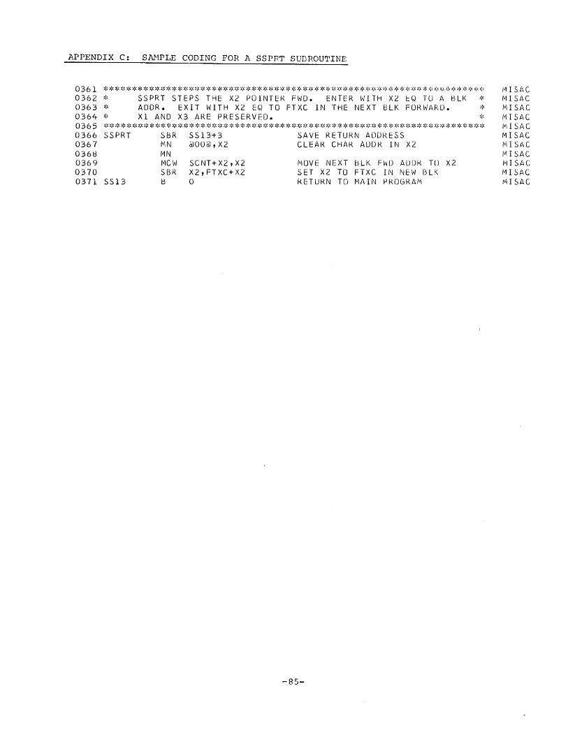
APPENDIX C: SANPLE CODING FOR A SSPRT SUDROUTINE
0361 ******************************************************************* 0362 * SSPRT STEPS THE X2 POINTER FWD. ENTER WITH X2 EO TU A BlK * 0363 * ADDR. EXIT WITH X2 EO TO FTXC IN THE NEXT BlK FORWARD. * 0364 * Xl AND X3 ARE PRESERVED. * 0365 ******************************************************************* 0366 SSPRT SBR SS13+3 SAVE RETURN ADDRESS 0367 MN @00@,X2 CLEAR CHAR ADDR IN X2 0368 MN 0369 MCW SCNT+X2,X2 0370 SBR X2,FTXC+X2 0371 5S13 B 0
MOVE NEXT BlK FWD ADDR TU X2 SET X2 TO FTXC IN NEW BlK RETURN TO MAIN PROGRAM
-85-
jll\!st\C {V1 I SAC MISAC 1"1 I S/'C Ivl I SA C MISAC MISAC MISAC jV1ISAC IV] I SAC 11/1 I SAC

APPENDIX D: SAMPLE CODING FOR A ROUTINE TO READ OVERLAYS
0354 ******************************************************************* 0355 * RFOVY WILL READ THE FIRST OVERLAY. ALL INDEXES ARE * 0356 * PRESERVED * 0357 ******************************************************************* 0358 RFOVY SBR RD20+3 SAVE RETURN ADDRESS . 0359 MCW @2@,RFll MOVE 1ST OVLY INCREMENT TO CHECK 0360 RF08 MCW OVAREA-5,RFI0 MOVE IN BASIC DSK ADDRS FOR CHECK 0361 A RF11,RF10 INCREMENT BASIC ADDRS FOR OVRLY 0362 C HFTRAR-5,RFIO IS OVRLY ALREADY IN 0363 BE RD20 YES, ABORT READ 0364 MCW RF10,HFTRAR-5 NO, SET DISK ADDRESS FOR OVRLY 0365 MCW @!@,RE17 SET lOOP FOR READ, HI PRIORITY 0366 SBR RE18,HFTRAR-10 SET IOAR 0367 B RE12 BRANCH FOR I/O 0368 RF10 DCW =3 CHECK REGISTER FOR OVRLY ADDRS 0369 RF11 DCW =1 INCREMENTAL REGISTER FOR OVRLY 0370 ******************************************************************* 0371 * RSOVY WILL READ THE SECOND OVERLAY. ALL INDEXES ARE * 0372 * PRESERVED * 0373 ******************************************************************* 0374 RSOVY SBR RD20+3 SAVE RETURN ADDRESS 0375 MCW @3@,RF11 MOVE IN 2ND OVRLY INCREMENT 0376 B RF08 BRANCH FOR I/O 0377 ******************************************************************* 0378 * RTHVY WILL READ THE THIRD OVERLY. ALL INDEXES ARE * 0379 * PRESERVED * 0380 ******************************************************************* 0381 RTHVY SBR RD20+3 SAVE RETURN ADDRESS 0382 RF01 MCW @4@,RF11 MOVE IN 3RD OVRLY INCREMENT 0383 B RF08 BRANCH FOR 10
0384 ******************************************************************* 0385 * RFTOVY WILL READ THE FOURTH OVERLAY. ALL INDEXES ARE * 0386 * PRESERVED. * 0387 ******************************************************************* 0388 RFTVY SBR RD20+3 SAVE RETURN ADDRESS 0389 MCW @5@,RF11 MOVE IN 4TH OVRLY INCREMENT 0390 B RF08 BRANCH FOR I/O 0391 ******************************************************************* 0392 * RFFVY WILL READ THE FIFTH OVERLAY. ALL INDEXES ARE * 0393 * PRESERVED 0394 ******************************************************************* 0395 RFFVY SBR RD20+3 SAVE RETURN ADDRESS 0396 MCW @6@,RF11 MOVE IN 5TH OVRLY INCREMENT 0397 B RF08 BRANCH FOR I/O 0398 ******************************************************************* 0399 * RSXVY WILL READ THE SIXTH OVERLAY. ALL INDEXES ARE * 0400 * PRESERVED. * 0401 ******************************************************************* 0402 RSXVY SBR R020+3 SAVE RETURN ADDRESS 0403 RF02 MCW @7@,RFll SET 6TH OVLY INCREMENT 0404 B RF08 BRANCH TO READ IN OVERLAY
-86-
KLCUT KLCUT KLCUT KLCUT KLCUT KLCUT KLCUT KLCUT KLCUT KLCUT KLCUT KLCUT KLCUT KLCUT KLCUT KLCUT KLCUT KLCUT KLCUT KLCUT KLCUT KLCUT KLCUT KLCUT KLCUT KLCUT KLCUT KLCUT KLCUT KLCUT KLCUT KLCUT KLCUT KLCUT KLCUT KLCUT KLCUT KLCUT KLCUT KLCUT KLCUT KLCUT KLCUT KLCUT KLCUT KLCUT KLCUT KLCUT KLCUT KLCUT KLCUT
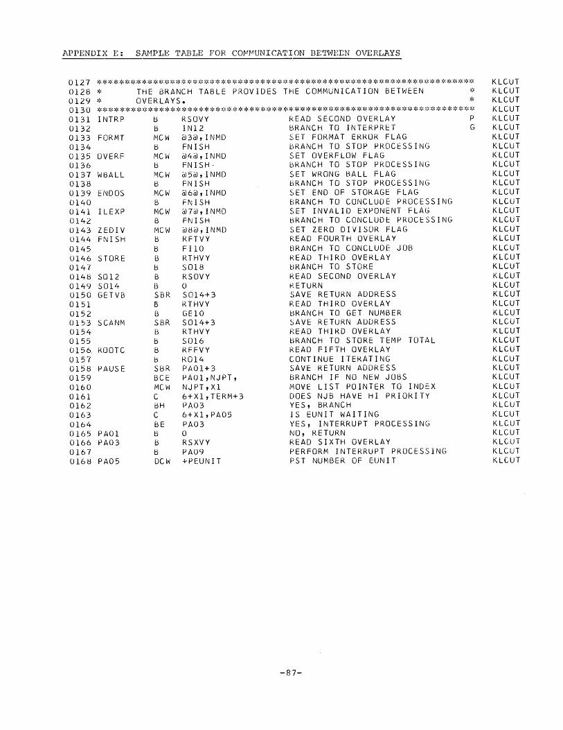
APPENDIX E: SAI'1PLE TABLE FOR cOr.1r~UNICATION BETWEEN OVERLAYS
0127 ******************************************************************* 0128 * THE BRANCH TABLE PROVIDES THE COMMUNICATION BETWEEN * 0129 * OVERLAYS. * 0130 ******************************************************************* 0131 INTRP b RSOVY READ SECOND OVERLAY P 0132 B IN12 BRANCH TO INTERPRET G 0133 FORMT MCW @3@,INMD SET FORMAT ERROR FLAG 0134 B FNISH BRANCH TO STOP PROCtSSING 0135 OVERF MCW @4@,INMD SET OVERFLOW FLAG 0136 b FNISH· BRANCH TO STOP PROCESSING 0137 WBALL MCW @5@,INMD SET WRONG BALL FLAG 0138 B FNISH BRANCH TO STOP PROCESSING 0139 ENDOS MCW @6@,INMD SET END OF STORAGE FLAG 0140 B FNISH BRANCH TO CONCLUDE PROCESSING 0141 ILEXP MCW @7@,INMD SET INVALID EXPONENT FLAG 0142 B FNISH bRANCH TO CONCLUDE PROCE~SING
0143 ZEDIV MCW @8@,INMD SET ZERO DIVISOR FLAG 0144 FNISH b RFTVY READ FOURTH OVERLAY 0145 B FI10 BRANCH TO CONCLUDE JOB 0146 STORE B RTHVY READ THIRD OVERLAY 0147 b 5018 BRANCH TO STORE 0148 S012 B RSOVY READ SECOND OVERLAY 0149 S014 B 0 RETURN 0150 GETVB SBR 5014+3 SAVE RETURN ADDRESS 0151 6 RTHVY READ THIRD OVERLAY 0152 B GEI0 BRANCH TO GET NUMBER 0153 SCANM SBR S014+3 SAVE RETURN ADDRESS 0154 B RTHVY READ THIRD OVERLAY 0155 b S016 BRANCH TO STORE TEMP TOTAL 0156. ROOTC B RFFVY READ FIFTH OVER-LAY 0157 b R014 CONTINUE ITERATING 0158 PAUSE SBR PAOl+3 SAVE RETURN ADDRESS 0159 BCE PA01,NJPT, BRANCH IF NO NEW JOBS 0160 MCW NJPT,Xl MOVE LIST POINTER TO INDEX 0161 C 6+Xl,TERM+3 DOES NJB HAVE HI PRIORITY 0162 bH PA03 YES, BRANCH 0163 C 6+Xl,PA05 IS EUNIT WAITING 0164 BE PA03 YES, INTERRUPT PROCESSING 0165 PAOl BONO, RETURN 0166 PA03 B RSXVY READ SIXTH OVERLAY 0167 b PA09 PERFORM INTERRUPT PROCESSING 0168 PA05 DCW +PEUNIT PST NUMBER OF EUNIT
-87-
KLCUT KLCUT KLCUT KLCUT KLCUT KLCUT KLCUT KLCUT KLCUT KLCUT KLCUT KLCUT KLCUT KLCUT KLCUT KLCUT KLCUT KLCUT KLCUT KLCUT KLCUT KLCUT KLCUT KLCUT KLCUT KLCUT KLCUT KLCUT KLCUT KLCUT KLCUT KLCUT KLCUT KLCUT KLCUT KLCUT KLCUT KLCUT KLCUT KLCUT KLCUT KLCUT

H20-0228-0
APPENDIX F: SAMPLE CODING FOR A SUBROUTINE TO CHAIN WORKING STORAGE TO ANOTHER BLOCK
******************************************************************* 0563 0564 ~:, CHAIN CHAINS WORKING STORAGE TO ANOTHER BLOCK -" ','
0565 0566 0567 0568 0569 0570 0571 0572 0573 0574 0575 0576 0577 0578 0579 0580 0581 0582 0583 0584 0585 0586 0587 0588 0589 0590 0591 0592 0593
******************************************************************* CHAIN
0594 CH20
SBR SBR SBR B S lrJ SBR B B CW MCW !VICW CW MA B B LCA LCA LCA MCW MCi'J MCW fvlCW B MCW LCA MN MN LCA
B
CH20+3 BL50,2+X2 BL49,SYSMSR CNXTO LTXC+1+X2 X3,NXBA+X2 NDBKX BL245 LTXC+1+X2 BL50,X3 GMWM,15999+X3 15999+X3 @I9I@,LCIB+X2 WRBLK NCBKX NXBA+X2,NXBA+X3 SADD+X2 X2 GMWM+l GMWM+l X3,BL50 X2,X3 FTFSX BL50,X2 NXBA+X2,SADD+X2 @01@,LCI13+X2
Q)L@,FTXC+X2 S
o
International Business Machines Corporation
Data Processing Division
112 East Post Road, White Plains, New York 10601
SAVE RETURN ADDRESS SET SVRA FOR END OF STORAGE ASSUME END OF STORAGE MESSAGE CLEAR X2 NUMERICS ASSUME END OF STORAGE SET NDBKX PARAMETER BRANCH FOR A DISK BLOCK NONE, TYPE END OF STORAGE CLEAR GMW/Vl GET WMDWNSHFT ADDRS IN INDEX END CURRENT 13LOCK WITH A GM NO GMWMS ALLOWED DECREMENT LINE COUNT BY 1 WRITE OUT OLD BLOCK GET A NEW CORE BLOCK GIVE BLOCK NEW ADDRESS SET BKWD CHAINING AND CRAD AND EW GMS
SAVE X3 POINTER GIVE OLD BLOCK TO X3 AND PURGE IT GIVE BLOCK ADDRESS TO X2 SET SADD IN NEW BLOCK SET LINE COUNT TO 1 IN BLK
START BLK WITH A WMDWNSHFT
RETURN
BLKOP BLKOP BLKOP BLKOP BLKOP BLKOP BLKOP BLKOP BLKUP BLKOP BLKOP BLKOP BLKOP BLKOP BLKOP BLKOP BLKOP BLKOP BLKOP BLKOP BLKOP BLKOP BLKOP BLKOP BLKOP BLKUP BLKUP BLKOP BLKOP BLKOP BLKOP
BLKOP


![[Pda Engines] Aiaa 2005 0228](https://img.pdfslide.us/doc/110x75/55299e8d4a7959b8158b481c/pda-engines-aiaa-2005-0228.jpg)