Embed Size (px)
Citation preview
1
H
- 2.8” Graphic Screen
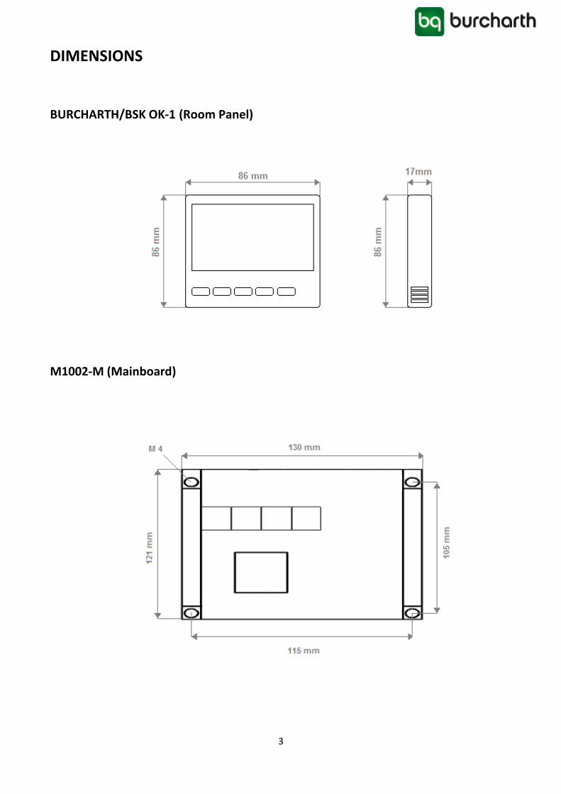
- 2 Part Control Panel (Mainboard + Room Panel)
- Aspirator, Vantilator 3 Level Speed Control
- Automatic/Manuel Mode
- 3 Stage Heater Control
- English/Turkish Language
- Carbon dioxide Control (CO2 Transmitter Input)
- Return Air Temperature Input (NTC 10K)
- BMS Input (Dry Contact)
- Dirty Filter Input
- On/Off Damper Output
- Minimum ve Maximum Set Temperature Limit
- Weekly Program (for BSK OK-1)
X: T > Weekly Program
Mainboard: M1002-M
Warning
Please read the manual and following cautions before you begin installing the device. Responsibility of accidents and damages caused by failure to observe the warnings in the manual belongs to user. Operation on the device cause damage to device and system. In this case damaged device will be out of warranty.
User Manual BURCHARTH/BSK OK-1
2
User Manual BURCHARTH/BSK OK-1 ENG-02/18
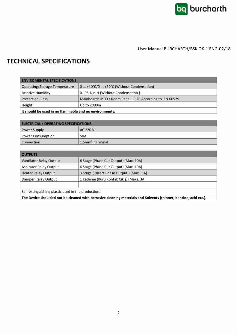
TECHNICAL SPECIFICATIONS
ENVIROMENTAL SPECIFICATIONS
Operating/Storage Temperature 0 ... +40°C/0 ... +50°C (Without Condensation)
Relative Humidity 0…95 % r. H (Without Condensation )
Protection Class Mainboard: IP 00 / Room Panel: IP 20 According to EN 60529
Height Up to 2000m
It should be used in no flammable and no environments.
ELECTRICAL / OPERATING SPECIFICATIONS
Power Supply AC 220 V
Power Consumption 5VA
Connection 1.5mm²' terminal
OUTPUTS
Vantilator Relay Output 6 Stage (Phase Cut Output) (Max. 10A)
Aspirator Relay Output 6 Stage (Phase Cut Output) (Max. 10A)
Heater Relay Output 3 Stage ( Direct Phase Output ) (Max . 3A)
Damper Relay Output 1 Kademe (Kuru Kontak Çıkış) (Maks. 3A)
Self-extinguishing plastic used in the production.
The Device shoulded not be cleaned with corrosive cleaning materials and Solvents (thinner, benzine, acid etc.).

4
Connections
M1002-M control devices are designed for HRV with mono stage fan or EC fan. The device should be used
according to instructions. There is no power on the device when mounting. The device should be protected
from vibration, humidity and pollution. Cross and shield cable should be use for signal and communication
signals.

5
CONNECTION DIAGRAM
The control board should be mounted in the box sunlight and humidity.
6
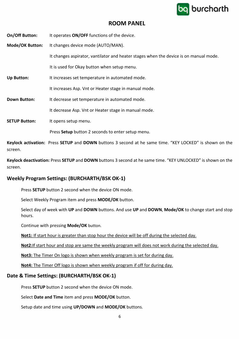
ROOM PANEL
On/Off Button: It operates ON/OFF functions of the device.
Mode/OK Button: It changes device mode (AUTO/MAN).
It changes aspirator, vantilator and heater stages when the device is on manual mode.
It is used for Okay button when setup menu.
Up Button: It increases set temperature in automated mode.
It increases Asp. Vnt or Heater stage in manual mode.
Down Button: It decrease set temperature in automated mode.
It decrease Asp. Vnt or Heater stage in manual mode.
SETUP Button: It opens setup menu.
Press Setup button 2 seconds to enter setup menu.
Keylock activation: Press SETUP and DOWN buttons 3 second at he same time. “KEY LOCKED” is shown on the
screen.
Keylock deactivation: Press SETUP and DOWN buttons 3 second at he same time. “KEY UNLOCKED” is shown on the
screen.
Weekly Program Settings: (BURCHARTH/BSK OK-1)
Press SETUP button 2 second when the device ON mode.
Select Weekly Program item and press MODE/OK button.
Select day of week with UP and DOWN buttons. And use UP and DOWN, Mode/OK to change start and stop hours.
Continue with pressing Mode/OK button.
Not1: If start hour is greater than stop hour the device will be off during the selected day.
Not2:If start hour and stop are same the weekly program will does not work during the selected day.
Not3: The Timer On logo is shown when weekly program is set for during day.
Not4: The Timer Off logo is shown when weekly program if off for during day.
Date & Time Settings: (BURCHARTH/BSK OK-1)
Press SETUP button 2 second when the device ON mode.
Select Date and Time item and press MODE/OK button.
Setup date and time using UP/DOWN and MODE/OK buttons.
7
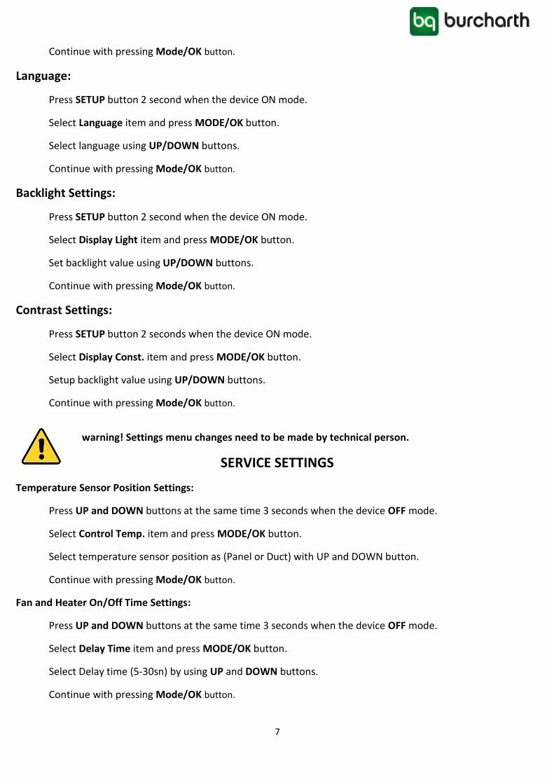
Continue with pressing Mode/OK button.
Language:
Press SETUP button 2 second when the device ON mode.
Select Language item and press MODE/OK button.
Select language using UP/DOWN buttons.
Continue with pressing Mode/OK button.
Backlight Settings:
Press SETUP button 2 second when the device ON mode.
Select Display Light item and press MODE/OK button.
Set backlight value using UP/DOWN buttons.
Continue with pressing Mode/OK button.
Contrast Settings:
Press SETUP button 2 seconds when the device ON mode.
Select Display Const. item and press MODE/OK button.
Setup backlight value using UP/DOWN buttons.
Continue with pressing Mode/OK button.
warning! Settings menu changes need to be made by technical person.
SERVICE SETTINGS
Temperature Sensor Position Settings:
Press UP and DOWN buttons at the same time 3 seconds when the device OFF mode.
Select Control Temp. item and press MODE/OK button.
Select temperature sensor position as (Panel or Duct) with UP and DOWN button.
Continue with pressing Mode/OK button.
Fan and Heater On/Off Time Settings:
Press UP and DOWN buttons at the same time 3 seconds when the device OFF mode.
Select Delay Time item and press MODE/OK button.
Select Delay time (5-30sn) by using UP and DOWN buttons.
Continue with pressing Mode/OK button.
8
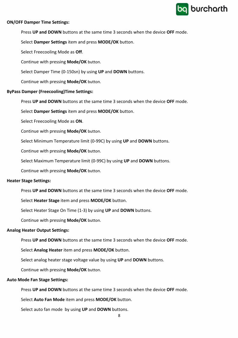
ON/OFF Damper Time Settings:
Press UP and DOWN buttons at the same time 3 seconds when the device OFF mode.
Select Damper Settings item and press MODE/OK button.
Select Freecooling Mode as Off.
Continue with pressing Mode/OK button.
Select Damper Time (0-150sn) by using UP and DOWN buttons.
Continue with pressing Mode/OK button.
ByPass Damper (Freecooling)Time Settings:
Press UP and DOWN buttons at the same time 3 seconds when the device OFF mode.
Select Damper Settings item and press MODE/OK button.
Select Freecooling Mode as ON.
Continue with pressing Mode/OK button.
Select Minimum Temperature limit (0-99C) by using UP and DOWN buttons.
Continue with pressing Mode/OK button.
Select Maximum Temperature limit (0-99C) by using UP and DOWN buttons.
Continue with pressing Mode/OK button.
Heater Stage Settings:
Press UP and DOWN buttons at the same time 3 seconds when the device OFF mode.
Select Heater Stage item and press MODE/OK button.
Select Heater Stage On Time (1-3) by using UP and DOWN buttons.
Continue with pressing Mode/OK button.
Analog Heater Output Settings:
Press UP and DOWN buttons at the same time 3 seconds when the device OFF mode.
Select Analog Heater item and press MODE/OK button.
Select analog heater stage voltage value by using UP and DOWN buttons.
Continue with pressing Mode/OK button.
Auto Mode Fan Stage Settings:
Press UP and DOWN buttons at the same time 3 seconds when the device OFF mode.
Select Auto Fan Mode item and press MODE/OK button.
Select auto fan mode by using UP and DOWN buttons.

9
Continue with pressing Mode/OK button.
Carbon dioxide Settings:
Press UP and DOWN buttons at the same time 3 seconds when the device OFF mode.
Select CO2 Mode item and press MODE/OK button.
Select Carbon dioxide mode (On/Off) by using UP and DOWN buttons.
Continue with pressing Mode/OK button.
Minimum Set Temperature Settings:
Press UP and DOWN buttons at the same time 3 seconds when the device OFF mode.
Select “Set Min.” item and press MODE/OK button.
Select Minimum temperate set limit by using UP and DOWN buttons.
Continue with pressing Mode/OK button.
Maximum Set Temperature Settings:
Press UP and DOWN buttons at the same time 3 seconds when the device OFF mode.
Select “Set Max.” item and press MODE/OK button.
Select Maximum temperate set limit by using UP and DOWN buttons.
Continue with pressing Mode/OK button.
Analog Output Selection Settings:
Press UP and DOWN buttons at the same time 3 seconds when the device OFF mode.
Select “Analog Output” item and press MODE/OK button.
Select Analog Output type by using UP and DOWN buttons.
Continue with pressing Mode/OK button.
Fan Stage Settings:
Press UP and DOWN buttons at the same time 3 seconds when the device OFF mode.
Select “Fan Stage” item and press MODE/OK button.
Select Fan stage(1-6) by using UP and DOWN buttons.
Continue with pressing Mode/OK button.
Fan Level Settings:
Press UP and DOWN buttons at the same time 3 seconds when the device OFF mode.
Select “Fan Level” item and press MODE/OK button.
Select Fan voltage level of aspirator and vantilator by using UP and DOWN buttons.

10
Continue with pressing Mode/OK button.
Room Panel Communication Settings Ayarı:
Press UP and DOWN buttons at the same time 3 seconds when the device OFF mode.
Select “Panel Settings” item and press MODE/OK button.
Select Modbus ID (1-255) by using UP and DOWN buttons.
Continue with pressing Mode/OK button.
Select Modbus Baudrate (1200Bps, 2400 Bps, 4800 Bps, 9600Bps, 19200Bps,38400Bps) by using UP and DOWN buttons.
Continue with pressing Mode/OK button.
Note1: Communication Settings: Data Bits:8, None Parity Stop Bit 1
Modbus RTU Communication Settings:
Press UP and DOWN buttons at the same time 3 seconds when the device OFF mode.
Select “Modbus Settings” item and press MODE/OK button.
Select Modbus ID (1-255) by using UP and DOWN buttons.
Continue with pressing Mode/OK button.
Select Modbus Baudrate (1200Bps, 2400 Bps, 4800 Bps, 9600Bps, 19200Bps,38400Bps) by using UP and DOWN buttons.
Continue with pressing Mode/OK button.
Note1: Communication Settings: Data Bits:8, None Parity Stop Bit 1
Panel Factory Reset:
Press UP and DOWN buttons at the same time 3 seconds when the device OFF mode.
Select “Factory Reset” item and press MODE/OK button.
Select ON Mode on the factory reset menu.
Continue with pressing Mode/OK button.
Room Panel will be return default parameters value.
Room Panel Factory Settings:
Backlight: %50
Contrast: %50
Panel Communication: Modbus ID: 1
Modbus Baudarate: 9600 Bps
11
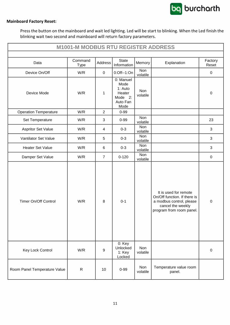
Mainboard Factory Reset:
Press the button on the mainboard and wait led lighting. Led will be start to blinking. When the Led finish the blinking wait two second and mainboard will return factory parameters.
M1001-M MODBUS RTU REGISTER ADDRESS
Data Command
Type Address
State Information
Memory Explanation Factory Reset
Device On/Off W/R 0 0:Off--1:On Non
volatile 0
Device Mode W/R 1
0: Manuel Mode
1: Auto Heater
Mode 2: Auto Fan
Mode
Non volatile
0
Operation Temperature W/R 2 0-99
Set Temperature W/R 3 0-99 Non
volatile 23
Aspritor Set Value W/R 4 0-3 Non
volatile 3
Vantilator Set Value W/R 5 0-3 Non
volatile 3
Heater Set Value W/R 6 0-3 Non
volatile 3
Damper Set Value W/R 7 0-120 Non
volatile 0
Timer On/Off Control W/R 8 0-1
It is used for remote On/Off function. If there is a modbus control, please
cancel the weekly program from room panel.
0
Key Lock Control W/R 9
0: Key Unlocked
1: Key Locked
Non volatile
0
Room Panel Temperature Value R 10 0-99 Non
volatile Temperature value room
panel.
12
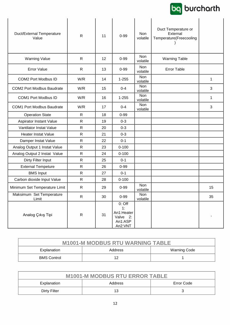
Duct/External Temperature Value
R 11 0-99 Non
volatile
Duct Temperature or External
Temperature(Freecooling)
Warning Value R 12 0-99 Non
volatile Warning Table
Error Value R 13 0-99 Non
volatile Error Table
COM2 Port Modbus ID W/R 14 1-255 Non
volatile 1
COM2 Port Modbus Baudrate W/R 15 0-4 Non
volatile 3
COM1 Port Modbus ID W/R 16 1-255 Non
volatile 1
COM1 Port Modbus Baudrate W/R 17 0-4 Non
volatile 3
Operation State R 18 0-99
Aspirator Instant Value R 19 0-3
Vantilator Instat Value R 20 0-3
Heater Instat Value R 21 0-3
Damper Instat Value R 22 0-1
Analog Output 1 Instat Value R 23 0-100
Analog Output 2 Instat Value R 24 0-100
Dirty Filter Input R 25 0-1
External Tempeture R 26 0-99
BMS Input R 27 0-1
Carbon dioxide Input Value R 28 0-100
Minimum Set Temperature Limit R 29 0-99 Non
volatile 15
Maksimum Set Temperature Limit
R 30 0-99 Non
volatile 35
Analog Çıkış Tipi R 31
0: Off 1:
An1:Heater Valve 2: An1:ASP An2:VNT
,
M1001-M MODBUS RTU WARNING TABLE
Explanation Address Warning Code
BMS Control 12 1
M1001-M MODBUS RTU ERROR TABLE
Explanation Address Error Code
Dirty Filter 13 3