Embed Size (px)
Citation preview

GWPD 14—Measuring continuous water levels by use of a float-activated recorder
VERSION: 2010.1
PURPOSE: To make continuous water-level measurements in a well using a float-activated recorder.
For some hydrogeologic studies, frequent and uninter-rupted water-level measurements may be needed to identify unique properties of the groundwater flow system. In studies in which a more complete picture of water-level fluctuations is needed, automatic float-activated water-level recorders can be installed. Float-activated recorders sense changes in water level by the movement of a weight-balanced float that is low-ered into the well.
Materials and InstrumentsThere are several types of float-activated recording
devices. The float or water-level sensing mechanism has not changed much through time. The recording devices have evolved over time from graphical devices to punch tapes to electronic data loggers.1. Float and non-lead counterweight
2. Small diameter stranded cable or a flat steel tape
3. Graphic recorder, data logger and incremental encoder, integrated data logger/encoder unit, or data collection platform (DCP)
4. Battery, spares, and wiring to connect battery to record-ing device
5. Tools, including digital multimeter, connectors, crimping tool, and contact-burnishing tool
6. Watch
7. A water-level tape (steel or electric) graduated in hun-dredths of feet and other materials necessary for depth-to-water measurement
8. Recorder shelter with lock and key
9. Field notebook
10. Pencil or pen, blue or black ink. Strikethrough, date and initial errors; no erasures
11. Water-level measurement field form
Data Accuracy and Limitations
1. The initial water-level setting for a float-activated recorder should be determined using a graduated steel or electric tape which is commonly accurate to 0.01 foot.
2. Each time a float-activated recorder is serviced, calibra-tion check water-level measurements should be made. Data recorded using this procedure are only as accurate as the calibration measurements.
3. Where depth to water is greater than a few feet below the top of the casing, special care should be taken to mini-mize friction between the float cable and the walls of the well. The float selected should be the largest diameter that can be accommodated by the well casing without excessive friction.
4. Although float-activated recorders can be used success-fully in wells that are 2 inches in diameter, in order to avoid friction between the float cable and the walls of the well, 3-inch diameter wells and larger are preferable.
5. Float-activated recorders cannot be used in flowing wells, angled wells, or wells with very deep water levels.
118 Groundwater Technical Procedures of the U.S. Geological Survey
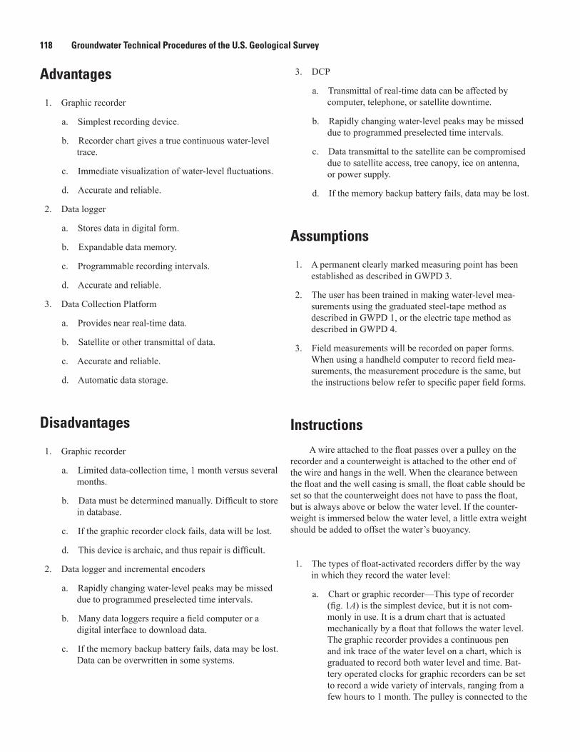
Advantages
1. Graphic recorder
a. Simplest recording device.
b. Recorder chart gives a true continuous water-level trace.
c. Immediate visualization of water-level fluctuations.
d. Accurate and reliable.
2. Data logger
a. Stores data in digital form.
b. Expandable data memory.
c. Programmable recording intervals.
d. Accurate and reliable.
3. Data Collection Platform
a. Provides near real-time data.
b. Satellite or other transmittal of data.
c. Accurate and reliable.
d. Automatic data storage.
Disadvantages
1. Graphic recorder
a. Limited data-collection time, 1 month versus several months.
b. Data must be determined manually. Difficult to store in database.
c. If the graphic recorder clock fails, data will be lost.
d. This device is archaic, and thus repair is difficult.
2. Data logger and incremental encoders
a. Rapidly changing water-level peaks may be missed due to programmed preselected time intervals.
b. Many data loggers require a field computer or a digital interface to download data.
c. If the memory backup battery fails, data may be lost. Data can be overwritten in some systems.
3. DCP
a. Transmittal of real-time data can be affected by computer, telephone, or satellite downtime.
b. Rapidly changing water-level peaks may be missed due to programmed preselected time intervals.
c. Data transmittal to the satellite can be compromised due to satellite access, tree canopy, ice on antenna, or power supply.
d. If the memory backup battery fails, data may be lost.
Assumptions
1. A permanent clearly marked measuring point has been established as described in GWPD 3.
2. The user has been trained in making water-level mea-surements using the graduated steel-tape method as described in GWPD 1, or the electric tape method as described in GWPD 4.
3. Field measurements will be recorded on paper forms. When using a handheld computer to record field mea-surements, the measurement procedure is the same, but the instructions below refer to specific paper field forms.
InstructionsA wire attached to the float passes over a pulley on the
recorder and a counterweight is attached to the other end of the wire and hangs in the well. When the clearance between the float and the well casing is small, the float cable should be set so that the counterweight does not have to pass the float, but is always above or below the water level. If the counter-weight is immersed below the water level, a little extra weight should be added to offset the water’s buoyancy.
1. The types of float-activated recorders differ by the way in which they record the water level:
a. Chart or graphic recorder—This type of recorder (fig. 1A) is the simplest device, but it is not com-monly in use. It is a drum chart that is actuated mechanically by a float that follows the water level. The graphic recorder provides a continuous pen and ink trace of the water level on a chart, which is graduated to record both water level and time. Bat-tery operated clocks for graphic recorders can be set to record a wide variety of intervals, ranging from a few hours to 1 month. The pulley is connected to the

GWPD 14—Measuring continuous water levels by use of a float-activated recorder 119
recorder drum by gears. A wide range of drum gears are available to set up the chart so that its rotation is proportional to the movement of the float. Fig-ure 1 shows a typical setup for a graphic water-level recorder using a guide pulley assembly (fig. 1B) in a small diameter well, as well as a standard position setup (fig. 1C). Data are retrieved by changing the paper chart.
b. Data logger and incremental encoder (fig. 2A)—Because the data logger and the encoder are separate units connected by a communication cable, this combination of instrumentation allows for a vari-ety of types of equipment to be used. Water-level changes sensed by the float are transferred into a digital signal by the incremental encoder. The digital signal from the incremental encoder is stored on the data logger. This instrumentation suite commonly requires a field computer or a digital interface to download the data.
c. Integrated data logger/incremental encoder units (fig. 2B)—This type of recorder combines a data log-ger and an incremental encoder into one unit. This instrumentation package has replaced the automated digital recorder (ADR punch tape) system. This instrument also requires a field computer or a digital interface to download data.
d. Data collection platform (DCP; fig. 2C)—A DCP provides real-time telemeter data using the Geosta-tionary Orbiting Environmental Satellite (GOES) system and can be interfaced with either an incre-mental encoder or integrated data logger/incremental encoder unit. Data are stored on a data logger and are transmitted to the satellite (GOES) on a fixed schedule (commonly 1 to 4-hour intervals) during a specific time “window.” Provided there are no data transmission problems, retrieval of the data is necessary only as a backup. A DCP also may use telephone or other communications technology for data transmission.
2. Select the recording device that best suits the water-level collection needs of the project.
3. Initial installation of the float-activated recorder:
a. Confirm that the well is unobstructed.
b. If the depth of the well is not known, measure the total depth as described in GWPD 11.
c. Install a suitable locking shelter that will protect instruments from weather and vandalism.
d. Establish a measuring point (MP) as described in GWPD 3. Record the MP in the well shelter.
e. Measure the depth to water in the well using either GWPD 1 or GWPD 4 to obtain an accurate water-level measurement with which to calibrate the recorder water level (initial calibration). Record the water-level measurement on the Inspection of Con-tinuous Record Well field form (fig. 3).
f. Orient the wheel containing the float tape or float wire and counterweight over the well opening. The float and counterweight must hang freely within the well casing; lack of freedom for the float and counterweight is one of the most common sources of error. The length of float tape or wire should be determined from the expected range of water-level fluctuation; the float should always rest on the water
Guide pulleyassembly
A
A. Standard float operated graphic water-level recorder (U.S. Bureau of Reclamation, 2001).
B
B. Showing use of a guide pully position counterweight inside a small diameter well
C
C. Standard position setup
Kay will rewrite fig caption with A–C included
CounterweightFloat
Drum
Recorder chart
Pulley
Figure 1. (A) Standard float operated graphic water-level recorder, (B) showing use of a guide pulley assembly to position counterweight inside a small diameter well, and (C) a standard position setup.
Figure 1. A, Standard float-activated graphic water-level recorder (U.S. Bureau of Reclamation, 2001). B, Use of a guide pulley assembly to position counterweight inside a small diameter well. C, Standard position setup.

120 Groundwater Technical Procedures of the U.S. Geological Survey
Figure 2. Photographs of data logger and float installations: (A) data logger and incremental encoder, (B) Integrated data logger/encoder, and (C) data logger, encoder, and satellite-transmission equipment.
A. Data logger and incremental encoder
C. Data logger, encoder, and satellite-transmission equipment B. Integrated data logger/encoder,
Figure 2. A, Data logger and incremental encoder. B, Integrated data logger/encoder. C, Data logger, encoder, and satellite-transmission equipment. Brand names are for illustration purposes only and do not imply endorsement by the U.S. Geological Survey. (Photographs by W.L. Cunningham.)
surface, and the counterweight should always be suspended between the wheel and the water surface. A guide pulley assembly (fig. 1B) may be needed for the counterweight. Orient the wheel appropriately, and secure the wheel device and guide pulley assem-bly to the well shelter to prevent future movement.
g. Balance the float and cable on one side of the pulley against the weight and cable hanging on the opposite side of the pulley. Test the movement of the float wheel by carefully rotating it several inches and releasing it. The tape/recorder should quickly return to the initial value. If it does not return to within 0.01 foot of the initial value, inspect the float tape/wire, float, and counterweight and repair as necessary.

GWPD 14—Measuring continuous water levels by use of a float-activated recorder 121
SITE INFORMATION
SITE ID (C1)
Station name (C12)
airline, analog, calibratedairline,
estimated, pressuregage,
calibratedpress. gage,
geophysi-cal logs,
manometer, non-rec.gage,
reported, steeltape,
electrictape,
calibratedelec. tape
other
METHOD OF WATER-LEVELMEASUREMENT(C239) A B C E G H L M N R S T V Z
other
SITE STATUSFOR WATERLEVEL (C238) dry,
Drecentlyflowing,
Eflowing,
Fnearbyflowing
Gnearbyrecentlyflowing,
Hinjector
site,
Iinjector
sitemonitor,
Jmeasure-
mentdiscon.,
Nplugged,
Mobstruc-
tion,
Opumping,
Precentlypumped,
Rnearby
pumping,
Snearbyrecentlypumped,
Tforeignsub-
stance,
Vwelldes-
troyed,
Wsurfacewater
effects,
X Zstatic
BLANK
MEASURING POINT DATA (for MP Changes)
Time
Hold
Cut
Tape correction
WL below MP
MP correction
WL below LSD
Measured by
Remarks
BEGINNINGDATE(C321)
month day year
M.P. REMARKS (C324)
ENDINGDATE(C322)
M.P. HEIGHT (C323)NOTE: (-) for MP
below land surface
INSPECTION OF CONTINUOUS RECORD WELLSteel Tape or Calibrated Electric Tape Measurement
Final Measurement for GWSI
TIME
(C709)DATE WATER LEVEL MEASURED (C235)
month day year
STATUS
(C238)
METHOD
(C239)
TYPE
(C243)
WATER LEVEL
(C237)
Date of Field VisitMeasurement Tape ID
(GWPD1) (GWPD4)
WATER LEVEL TYPE CODE (C243) L M S
belowland
surface
belowmeas.
pt.
sealevel
Barometric Pressure _________ Air Temperature _________
DATA LOGGER VISIT INFO:
Local time: _________ GMT_________ Data logger time: ______
Sensor readingon arrival: _______ on departure: ________ RESET? Y / N
Datum Correction Needed: ____________________
Retreive data From: ______________ To: _________________
Datafile: __________________________________
Remarks: ______________________________________________
______________________________________________________
______________________________________________________
______________________________________________________
Battery Voltage __________ Replaced? Y / N
Measurement Method: Transducer Float
Checked Float/encoder? Y / N Checked Transducer? Y / N
Figure 3. Example water-level measurement field form for continuous recorders. This form, or an equivalent custom-designed form should be used for continuous recorder inspections and field measurements.
1 2 3
Sensor reading
date/time date/time
Figure 3. Water-level measurement field form for inspection of continuous record wells. This form, or an equivalent custom-designed form, should be used for continuous recorder inspections and field measurements.

122 Groundwater Technical Procedures of the U.S. Geological Survey
h. Confirm that the direction of the wheel movement is properly recorded (on the display, or by the data log-ger). For example, when recording depth to water, if the depth to water reading increases as the float is raised, the float was put on in reverse. Correct this error by reversing the direction of the float tape/wire.
i. Set the data logger to the depth to water measured in (e) above using the datum of choice and set the correct time.
j. Measure again to confirm, reset if necessary.
k. Record the water-level measurement on the Inspec-tion of Continuous Record Well field form (fig. 3).
l. Document the equipment serial numbers or other identifiers in the field notebook or on appropriate field forms.
m. Check the battery voltage. Replace if necessary.
n. Confirm that the data logger is operating prior to departure.
4. Subsequent visits to the float-activated recorder:
a. Retrieve groundwater data by using instrument or data logger software.
b. Inspect the equipment to confirm that installation is operating properly. Document the current water level recorded by the sensor (not the most recent water level recorded by the data logger).
c. Measure the depth to water in the well by using either GWPD 1 or GWPD 4 to obtain an accurate water-level measurement with which to check the recorder water level (calibration measurement)
d. Record the water-level measurement on the Inspec-tion of Continuous Record Well field form (fig. 3).
e. Test the movement of the float wheel by carefully rotating it several inches and releasing it. The tape/recorder should return to the same value. If it does not return to within 0.01 foot of the initial value, then inspect the float tape/wire, float, and counterweight and rebalance as necessary
f. Confirm that the direction of the wheel movement is properly recorded (on the display or by the data logger). If the depth to water reading increases as the float is raised, the float was put on in reverse. Correct this error by reversing the direction of the float tape/wire.
g. If the tape measurement differs from the instanta-neous instrumentation reading by an amount specified in the groundwater quality assurance procedures of the local office, record it on the inspection sheet and reset the instrumentation to reflect the proper depth to water.
h. Check the battery voltage. Replace if necessary.
i. Make sure the data logger is operating prior to depar-ture.
Data RecordingAll data are recorded in the field notebook and on the
appropriate field form.
References
Bureau of Reclamation, 2001, Water measurement manual, A water resources technical publication (2d ed. rev. reprinted): U.S. Department of the Interior, 485 p., accessed Decem-ber 17, 2010, at http://www.usbr.gov/pmts/hydraulics_lab/pubs/wmm/.
Garber, M.S., and Koopman, F.C., 1968, Methods of measur-ing water levels in deep wells: U.S. Geological Survey Techniques of Water-Resources Investigations, book 8, chap. A1, 23 p.
Cunningham, W.L., and Schalk, C.W., comps., 2011a, Ground-water technical procedures of the U.S. Geological Survey, GWPD 1—Measuring water levels by use of a graduated steel tape: U.S. Geological Survey Techniques and Methods 1–A1, 4 p.
Cunningham, W.L., and Schalk, C.W., comps., 2011b, Groundwater technical procedures of the U.S. Geological Survey, GWPD 3—Establishing a permanent measuring point and other reference marks: U.S. Geological Survey Techniques and Methods 1–A1, 13 p.
Cunningham, W.L., and Schalk, C.W., comps., 2011c, Ground-Water technical procedures of the U.S. Geological Survey, GWPD 4—Measuring water levels by use of an electric tape: U.S. Geological Survey Techniques and Methods 1–A1, 6 p.
U.S. Geological Survey, Office of Water Data Coordination, 1977, National handbook of recommended methods for water-data acquisition: Office of Water Data Coordination, Geological Survey, U.S. Department of the Interior, chap. 2, p. 2-12–2-14.