Embed Size (px)
Citation preview

G u i d e f o r C r e w H a b i t a b i l i t y o n W o r k b o a t s
GUIDE FOR
CREW HABITABILITY ON WORKBOATS
FEBRUARY 2012 (Updated September 2014 – see next page)
American Bureau of Shipping Incorporated by Act of Legislature of the State of New York 1862
Copyright 2012 American Bureau of Shipping ABS Plaza 16855 Northchase Drive Houston, TX 77060 USA
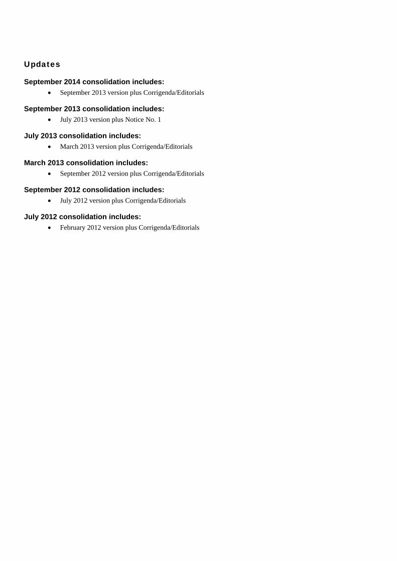
Updates
September 2014 consolidation includes: • September 2013 version plus Corrigenda/Editorials
September 2013 consolidation includes: • July 2013 version plus Notice No. 1
July 2013 consolidation includes: • March 2013 version plus Corrigenda/Editorials
March 2013 consolidation includes: • September 2012 version plus Corrigenda/Editorials
September 2012 consolidation includes: • July 2012 version plus Corrigenda/Editorials
July 2012 consolidation includes: • February 2012 version plus Corrigenda/Editorials
ABS GUIDE FOR CREW HABITABILITY ON WORKBOATS . 2012 iii
F o r e w o r d
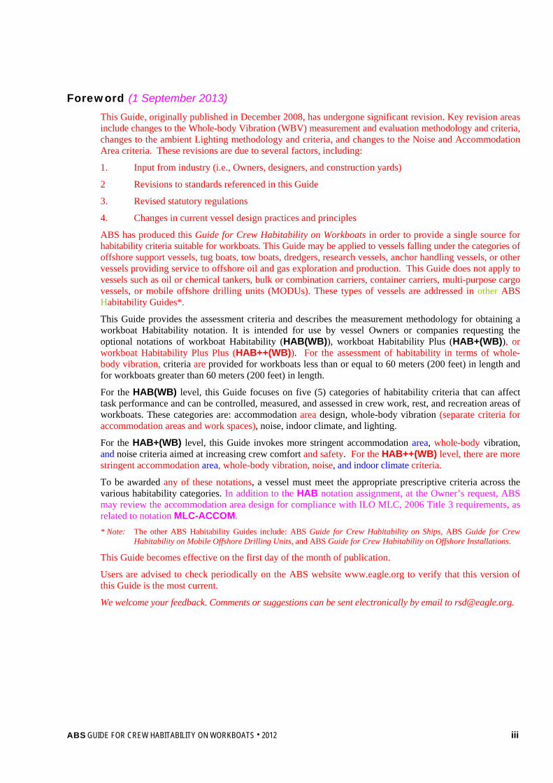
Foreword (1 September 2013) This Guide, originally published in December 2008, has undergone significant revision. Key revision areas include changes to the Whole-body Vibration (WBV) measurement and evaluation methodology and criteria, changes to the ambient Lighting methodology and criteria, and changes to the Noise and Accommodation Area criteria. These revisions are due to several factors, including:
1. Input from industry (i.e., Owners, designers, and construction yards)
2 Revisions to standards referenced in this Guide
3. Revised statutory regulations
4. Changes in current vessel design practices and principles
ABS has produced this Guide for Crew Habitability on Workboats in order to provide a single source for habitability criteria suitable for workboats. This Guide may be applied to vessels falling under the categories of offshore support vessels, tug boats, tow boats, dredgers, research vessels, anchor handling vessels, or other vessels providing service to offshore oil and gas exploration and production. This Guide does not apply to vessels such as oil or chemical tankers, bulk or combination carriers, container carriers, multi-purpose cargo vessels, or mobile offshore drilling units (MODUs). These types of vessels are addressed in other ABS Habitability Guides*.
This Guide provides the assessment criteria and describes the measurement methodology for obtaining a workboat Habitability notation. It is intended for use by vessel Owners or companies requesting the optional notations of workboat Habitability (HAB(WB)), workboat Habitability Plus (HAB+(WB)), or workboat Habitability Plus Plus (HAB++(WB)). For the assessment of habitability in terms of whole-body vibration, criteria are provided for workboats less than or equal to 60 meters (200 feet) in length and for workboats greater than 60 meters (200 feet) in length.
For the HAB(WB) level, this Guide focuses on five (5) categories of habitability criteria that can affect task performance and can be controlled, measured, and assessed in crew work, rest, and recreation areas of workboats. These categories are: accommodation area design, whole-body vibration (separate criteria for accommodation areas and work spaces), noise, indoor climate, and lighting.
For the HAB+(WB) level, this Guide invokes more stringent accommodation area, whole-body vibration, and noise criteria aimed at increasing crew comfort and safety. For the HAB++(WB) level, there are more stringent accommodation area, whole-body vibration, noise, and indoor climate criteria.
To be awarded any of these notations, a vessel must meet the appropriate prescriptive criteria across the various habitability categories. In addition to the HAB notation assignment, at the Owner’s request, ABS may review the accommodation area design for compliance with ILO MLC, 2006 Title 3 requirements, as related to notation MLC-ACCOM. * Note: The other ABS Habitability Guides include: ABS Guide for Crew Habitability on Ships, ABS Guide for Crew
Habitability on Mobile Offshore Drilling Units, and ABS Guide for Crew Habitability on Offshore Installations.
This Guide becomes effective on the first day of the month of publication.
Users are advised to check periodically on the ABS website www.eagle.org to verify that this version of this Guide is the most current.
We welcome your feedback. Comments or suggestions can be sent electronically by email to [email protected].
iv ABS GUIDE FOR CREW HABITABILITY ON WORKBOATS . 2012
T a b l e o f C o n t e n t s
GUIDE FOR
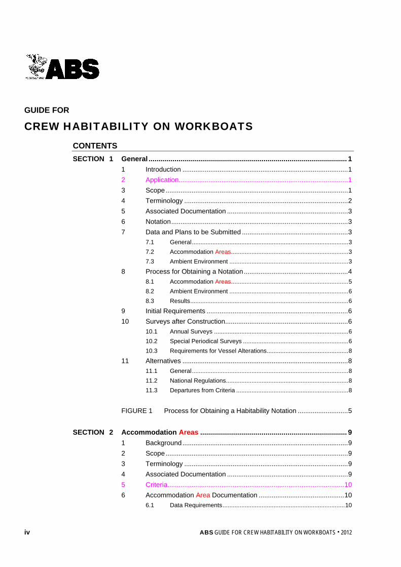
CREW HABITABILITY ON WORKBOATS CONTENTS SECTION 1 General .................................................................................................... 1
1 Introduction ......................................................................................... 1 2 Application ........................................................................................... 1 3 Scope .................................................................................................. 1 4 Terminology ........................................................................................ 2 5 Associated Documentation ................................................................. 3 6 Notation ............................................................................................... 3 7 Data and Plans to be Submitted ......................................................... 3
7.1 General ............................................................................................ 3 7.2 Accommodation Areas ..................................................................... 3 7.3 Ambient Environment ...................................................................... 3
8 Process for Obtaining a Notation ........................................................ 4 8.1 Accommodation Areas ..................................................................... 5 8.2 Ambient Environment ...................................................................... 6 8.3 Results ............................................................................................. 6
9 Initial Requirements ............................................................................ 6 10 Surveys after Construction .................................................................. 6
10.1 Annual Surveys ............................................................................... 6 10.2 Special Periodical Surveys .............................................................. 6 10.3 Requirements for Vessel Alterations ................................................ 8
11 Alternatives ......................................................................................... 8 11.1 General ............................................................................................ 8 11.2 National Regulations ........................................................................ 8 11.3 Departures from Criteria .................................................................. 8
FIGURE 1 Process for Obtaining a Habitability Notation ........................... 5
SECTION 2 Accommodation Areas .......................................................................... 9
1 Background ......................................................................................... 9 2 Scope .................................................................................................. 9 3 Terminology ........................................................................................ 9 4 Associated Documentation ................................................................. 9 5 Criteria ............................................................................................... 10 6 Accommodation Area Documentation .............................................. 10
6.1 Data Requirements ........................................................................ 10
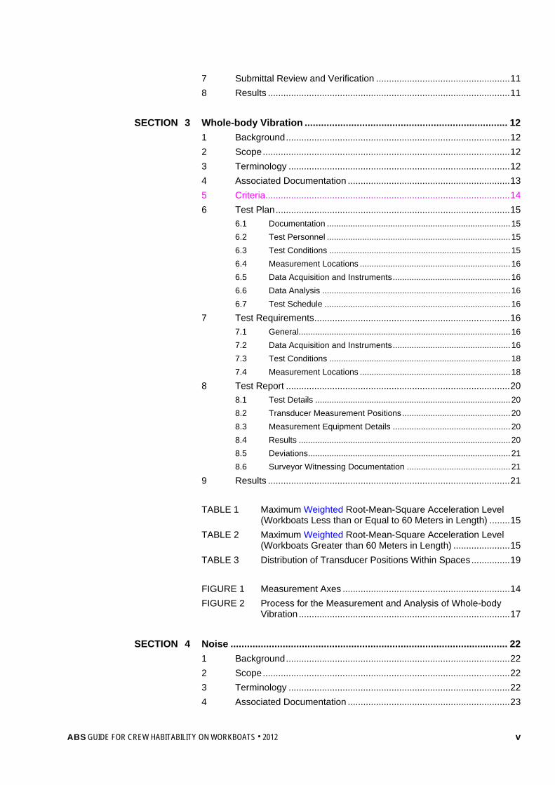
ABS GUIDE FOR CREW HABITABILITY ON WORKBOATS . 2012 v
7 Submittal Review and Verification .................................................... 11 8 Results .............................................................................................. 11
SECTION 3 Whole-body Vibration .......................................................................... 12
1 Background ....................................................................................... 12 2 Scope ................................................................................................ 12 3 Terminology ...................................................................................... 12 4 Associated Documentation ............................................................... 13 5 Criteria ............................................................................................... 14 6 Test Plan ........................................................................................... 15
6.1 Documentation .............................................................................. 15 6.2 Test Personnel .............................................................................. 15 6.3 Test Conditions ............................................................................. 15 6.4 Measurement Locations ................................................................ 16 6.5 Data Acquisition and Instruments .................................................. 16 6.6 Data Analysis ................................................................................ 16 6.7 Test Schedule ............................................................................... 16
7 Test Requirements ............................................................................ 16 7.1 General.......................................................................................... 16 7.2 Data Acquisition and Instruments .................................................. 16 7.3 Test Conditions ............................................................................. 18 7.4 Measurement Locations ................................................................ 18
8 Test Report ....................................................................................... 20 8.1 Test Details ................................................................................... 20 8.2 Transducer Measurement Positions .............................................. 20 8.3 Measurement Equipment Details .................................................. 20 8.4 Results .......................................................................................... 20 8.5 Deviations ...................................................................................... 21 8.6 Surveyor Witnessing Documentation ............................................ 21
9 Results .............................................................................................. 21 TABLE 1 Maximum Weighted Root-Mean-Square Acceleration Level
(Workboats Less than or Equal to 60 Meters in Length) ........ 15 TABLE 2 Maximum Weighted Root-Mean-Square Acceleration Level
(Workboats Greater than 60 Meters in Length) ...................... 15 TABLE 3 Distribution of Transducer Positions Within Spaces ............... 19 FIGURE 1 Measurement Axes ................................................................. 14 FIGURE 2 Process for the Measurement and Analysis of Whole-body
Vibration .................................................................................. 17 SECTION 4 Noise ..................................................................................................... 22
1 Background ....................................................................................... 22 2 Scope ................................................................................................ 22 3 Terminology ...................................................................................... 22 4 Associated Documentation ............................................................... 23
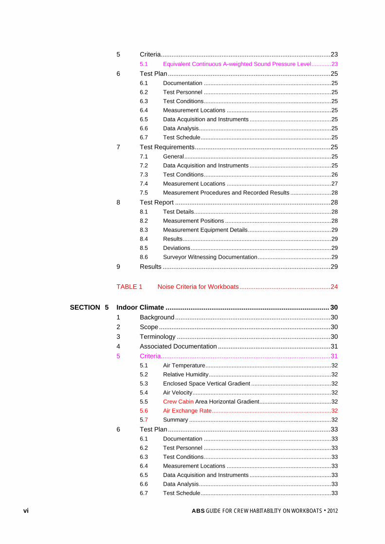
vi ABS GUIDE FOR CREW HABITABILITY ON WORKBOATS . 2012
5 Criteria ............................................................................................... 23 5.1 Equivalent Continuous A-weighted Sound Pressure Level ............ 23
6 Test Plan ........................................................................................... 25 6.1 Documentation .............................................................................. 25 6.2 Test Personnel .............................................................................. 25 6.3 Test Conditions .............................................................................. 25 6.4 Measurement Locations ................................................................ 25 6.5 Data Acquisition and Instruments .................................................. 25 6.6 Data Analysis ................................................................................. 25 6.7 Test Schedule ................................................................................ 25
7 Test Requirements ............................................................................ 25 7.1 General .......................................................................................... 25 7.2 Data Acquisition and Instruments .................................................. 25 7.3 Test Conditions .............................................................................. 26 7.4 Measurement Locations ................................................................ 27 7.5 Measurement Procedures and Recorded Results ......................... 28
8 Test Report ....................................................................................... 28 8.1 Test Details .................................................................................... 28 8.2 Measurement Positions ................................................................. 28 8.3 Measurement Equipment Details ................................................... 29 8.4 Results ........................................................................................... 29 8.5 Deviations ...................................................................................... 29 8.6 Surveyor Witnessing Documentation ............................................. 29
9 Results .............................................................................................. 29 TABLE 1 Noise Criteria for Workboats ................................................... 24
SECTION 5 Indoor Climate ...................................................................................... 30
1 Background ....................................................................................... 30 2 Scope ................................................................................................ 30 3 Terminology ...................................................................................... 30 4 Associated Documentation ............................................................... 31 5 Criteria ............................................................................................... 31
5.1 Air Temperature ............................................................................. 32 5.2 Relative Humidity ........................................................................... 32 5.3 Enclosed Space Vertical Gradient ................................................. 32 5.4 Air Velocity ..................................................................................... 32 5.5 Crew Cabin Area Horizontal Gradient ............................................ 32 5.6 Air Exchange Rate ......................................................................... 32 5.7 Summary ....................................................................................... 32
6 Test Plan ........................................................................................... 33 6.1 Documentation .............................................................................. 33 6.2 Test Personnel .............................................................................. 33 6.3 Test Conditions .............................................................................. 33 6.4 Measurement Locations ................................................................ 33 6.5 Data Acquisition and Instruments .................................................. 33 6.6 Data Analysis ................................................................................. 33 6.7 Test Schedule ................................................................................ 33
ABS GUIDE FOR CREW HABITABILITY ON WORKBOATS . 2012 vii
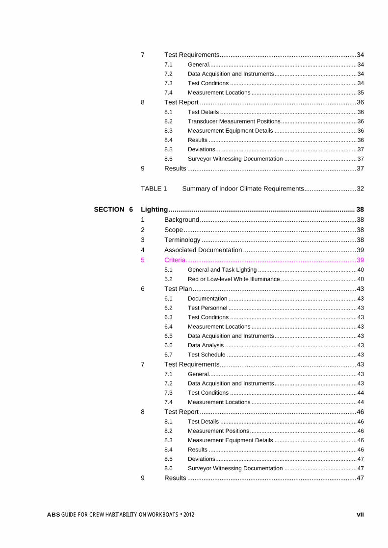
7 Test Requirements ............................................................................ 34 7.1 General.......................................................................................... 34 7.2 Data Acquisition and Instruments .................................................. 34 7.3 Test Conditions ............................................................................. 34 7.4 Measurement Locations ................................................................ 35
8 Test Report ....................................................................................... 36 8.1 Test Details ................................................................................... 36 8.2 Transducer Measurement Positions .............................................. 36 8.3 Measurement Equipment Details .................................................. 36 8.4 Results .......................................................................................... 36 8.5 Deviations ...................................................................................... 37 8.6 Surveyor Witnessing Documentation ............................................ 37
9 Results .............................................................................................. 37 TABLE 1 Summary of Indoor Climate Requirements ............................. 32
SECTION 6 Lighting ................................................................................................. 38
1 Background ....................................................................................... 38 2 Scope ................................................................................................ 38 3 Terminology ...................................................................................... 38 4 Associated Documentation ............................................................... 39 5 Criteria ............................................................................................... 39
5.1 General and Task Lighting ............................................................ 40 5.2 Red or Low-level White Illuminance .............................................. 40
6 Test Plan ........................................................................................... 43 6.1 Documentation .............................................................................. 43 6.2 Test Personnel .............................................................................. 43 6.3 Test Conditions ............................................................................. 43 6.4 Measurement Locations ................................................................ 43 6.5 Data Acquisition and Instruments .................................................. 43 6.6 Data Analysis ................................................................................ 43 6.7 Test Schedule ............................................................................... 43
7 Test Requirements ............................................................................ 43 7.1 General.......................................................................................... 43 7.2 Data Acquisition and Instruments .................................................. 43 7.3 Test Conditions ............................................................................. 44 7.4 Measurement Locations ................................................................ 44
8 Test Report ....................................................................................... 46 8.1 Test Details ................................................................................... 46 8.2 Measurement Positions ................................................................. 46 8.3 Measurement Equipment Details .................................................. 46 8.4 Results .......................................................................................... 46 8.5 Deviations ...................................................................................... 47 8.6 Surveyor Witnessing Documentation ............................................ 47
9 Results .............................................................................................. 47
viii ABS GUIDE FOR CREW HABITABILITY ON WORKBOATS . 2012
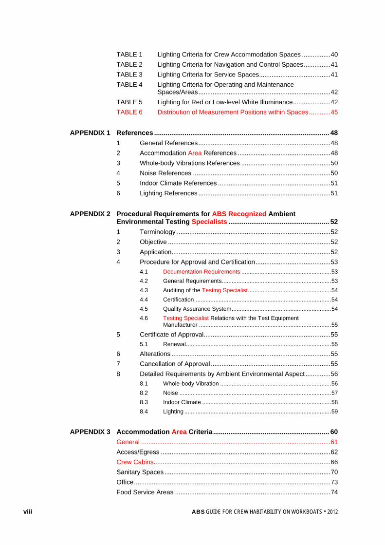
TABLE 1 Lighting Criteria for Crew Accommodation Spaces ................ 40 TABLE 2 Lighting Criteria for Navigation and Control Spaces ............... 41 TABLE 3 Lighting Criteria for Service Spaces ........................................ 41 TABLE 4 Lighting Criteria for Operating and Maintenance
Spaces/Areas .......................................................................... 42 TABLE 5 Lighting for Red or Low-level White Illuminance ..................... 42 TABLE 6 Distribution of Measurement Positions within Spaces ............ 45
APPENDIX 1 References ............................................................................................ 48
1 General References .......................................................................... 48 2 Accommodation Area References .................................................... 48 3 Whole-body Vibrations References .................................................. 50 4 Noise References ............................................................................. 50 5 Indoor Climate References ............................................................... 51 6 Lighting References .......................................................................... 51
APPENDIX 2 Procedural Requirements for ABS Recognized Ambient
Environmental Testing Specialists ..................................................... 52 1 Terminology ...................................................................................... 52 2 Objective ........................................................................................... 52 3 Application ......................................................................................... 52 4 Procedure for Approval and Certification .......................................... 53
4.1 Documentation Requirements ....................................................... 53 4.2 General Requirements ................................................................... 53 4.3 Auditing of the Testing Specialist ................................................... 54 4.4 Certification .................................................................................... 54 4.5 Quality Assurance System ............................................................. 54 4.6 Testing Specialist Relations with the Test Equipment
Manufacturer ................................................................................. 55 5 Certificate of Approval ....................................................................... 55
5.1 Renewal ......................................................................................... 55 6 Alterations ......................................................................................... 55 7 Cancellation of Approval ................................................................... 55 8 Detailed Requirements by Ambient Environmental Aspect .............. 56
8.1 Whole-body Vibration .................................................................... 56 8.2 Noise ............................................................................................. 57 8.3 Indoor Climate ............................................................................... 58 8.4 Lighting .......................................................................................... 59
APPENDIX 3 Accommodation Area Criteria ............................................................. 60
General .......................................................................................................... 61 Access/Egress ............................................................................................... 62 Crew Cabins ................................................................................................... 66 Sanitary Spaces ............................................................................................. 70 Office .............................................................................................................. 73 Food Service Areas ....................................................................................... 74
ABS GUIDE FOR CREW HABITABILITY ON WORKBOATS . 2012 ix
Recreation ...................................................................................................... 77 Laundry .......................................................................................................... 78 Medical ........................................................................................................... 79
APPENDIX 4 Acronyms and Abbreviations ............................................................. 80 APPENDIX 5 Associated Documentation ................................................................. 82

This Page Intentionally Left Blank
ABS GUIDE FOR CREW HABITABILITY ON WORKBOATS . 2012 1
S e c t i o n 1 : G e n e r a l
S E C T I O N 1 General
1 Introduction ABS recognizes the positive impact that suitable habitability criteria and design practices may have on the safety, productivity, morale, and overall well-being of seafarers. The ABS Guide for Crew Habitability on Workboats has been developed with the objective of improving the quality of crew member performance and comfort by improving working and living environments in terms of accommodation area design and ambient environmental qualities. These habitability criteria have been chosen to provide a means to help reduce crew fatigue, improve performance and safety, and to assist with crew recruiting and retention.
2 Application (1 September 2013) This Guide is applicable to new and existing vessels for which an optional workboat Habitability (HAB(WB)), workboat Habitability Plus (HAB+(WB)), or workboat Habitability Plus Plus (HAB++(WB)) notation has been requested. The habitability criteria are a measure of the acceptability of crew accommodation areas and work spaces for living and working. In addition to the HAB notation assignment, at the Owner’s request, ABS may review the accommodation area design for compliance with ILO MLC, 2006 Title 3 requirements, as related to notation MLC-ACCOM.
ABS has produced this Guide for Crew Habitability on Workboats in order to provide a single source for habitability criteria suitable for workboats. This Guide may be applied to vessels falling under the categories of offshore support vessels, tug boats, tow boats, dredgers, research vessels, anchor handling vessels, or other vessels providing service to offshore oil and gas exploration and production. This Guide does not apply to vessels such as oil or chemical tankers, bulk or combination carriers, container carriers, multi-purpose cargo vessels, or mobile offshore drilling units (MODUs). These types of vessels are covered and discussed in other ABS Habitability Guides.
3 Scope This Guide focuses on five (5) habitability aspects of workboat design and layout that can be controlled, measured, and assessed. These five (5) aspects are broken into two (2) categories in this Guide, accommodation areas and the ambient environment.
Accommodation area criteria pertain to dimensional and outfitting aspects of spaces and open deck areas where crew members eat, sleep, recreate, and perform routine daily activities.
The ambient environmental aspects of habitability pertain to the environment that the crew is exposed to during periods of work, leisure, and rest. Specifically, this Guide provides criteria, limits, and measurement methodologies for the following:
i) Whole-body Vibration (separate criteria for accommodation areas and work spaces)
ii) Noise
iii) Indoor Climate
iv) Lighting
The criteria provided in this Guide are based on currently available research data and standards for the purpose of improving crew performance and providing a base level of habitability and elements of safety related to habitability.
While producing this Guide, ABS has taken a practical approach to measurements, test personnel (Testing Specialists), and test equipment.
Section 1 General
2 ABS GUIDE FOR CREW HABITABILITY ON WORKBOATS . 2012
4 Terminology ABS Recognized Ambient Environmental Testing Specialists: Companies providing test or measurement services on behalf of the Owner of a vessel or shipyard for the purposes of meeting any of the ABS Habitability or Passenger Comfort notations.
Accommodation Areas/Accommodation Block: Vessel areas where the primary purpose is to rest and recreate. Accommodation spaces include cabins and staterooms, medical facilities (sick bays), offices, recreation rooms, and manned spaces within the accommodation block such as the bridge or control room. For the purposes of this Guide, accommodation areas also include service spaces such as mess rooms, laundry, and storerooms.
Ambient Environment: Ambient environment refers to the environmental conditions that the crew is exposed to during periods of work, leisure, or rest. Specifically, this Guide provides criteria and limits for whole-body vibration, noise, indoor climate, and lighting.
Associated Documentation: Documents referenced in this Guide that are needed to provide measuring techniques and further guidance.
Crew Member: Any person onboard a vessel, including the Master, who is not a passenger. This term is used interchangeably throughout this document with “seafarer”.
Crew Spaces: All areas on a vessel intended for seafarers only, such as seafarer accommodation spaces and seafarer work spaces. This term is also used interchangeably throughout this document with “seafarer spaces”.
Dynamic Positioning: A system to automatically maintain a workboat’s position and heading by controlling propellers and/or thrusters. Dynamic positioning can maintain a position to a fixed point over the bottom, or in relation to a moving object (such as another vessel). It can also be used to position the vessel at a favorable angle towards wind, waves, and current.
Habitability: The acceptability of the conditions of a vessel in terms of whole-body vibration, noise, indoor climate, and lighting, as well as physical and spatial characteristics, according to prevailing research and standards for human efficiency and comfort.
Manned Space: Any space where a seafarer may be present for twenty (20) minutes or longer at one time during normal, routine daily activities. Such spaces include working or living spaces.
Passenger: A passenger is every person other than the Master and the members of the crew or other persons employed or engaged in any capacity onboard a vessel for the business of that vessel.
Recreation and Public Spaces: Those portions of the accommodation areas that are used for halls, dining rooms, lounges, and similar permanently enclosed spaces.
Seafarer: Any person onboard a vessel, including the Master, who is not a passenger. This term is used interchangeably throughout this document with “crew member”.
Seafarer Spaces: All areas on a vessel intended for seafarers only, such as seafarer accommodation spaces and seafarer work spaces. This term is also used interchangeably throughout this document with “crew spaces”.
Shall: Expresses a provision that is mandatory.
Test Plan: Document containing the requisite information regarding vessel design and layout, test personnel, test conditions, measurement locations, data acquisition, instruments, data analysis, and test schedule necessary for verifying the measurements for the ambient environmental aspects of habitability.
Transit Conditions: Those conditions where the vessel is transitioning (moving) from one location to another.
Workboat: Vessels falling under the categories of offshore support vessels, tug boats, tow boats, dredgers, or research vessels and some special service vessels.
Work Spaces: Areas allocated for work. Categories of work spaces include, but are not limited to: navigation spaces, service spaces (galley, laundry) and machinery spaces.
Section 1 General
ABS GUIDE FOR CREW HABITABILITY ON WORKBOATS . 2012 3
5 Associated Documentation • Appendix 2, “Procedural Requirements for ABS Recognized Ambient Environmental Testing Specialists”
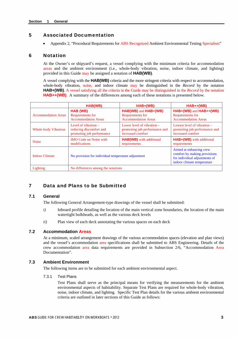
6 Notation At the Owner’s or shipyard’s request, a vessel complying with the minimum criteria for accommodation areas and the ambient environment (i.e., whole-body vibration, noise, indoor climate, and lighting) provided in this Guide may be assigned a notation of HAB(WB). A vessel complying with the HAB(WB) criteria and the more stringent criteria with respect to accommodation, whole-body vibration, noise, and indoor climate may be distinguished in the Record by the notation HAB+(WB). A vessel satisfying all the criteria in the Guide may be distinguished in the Record by the notation HAB++(WB). A summary of the differences among each of these notations is presented below.
HAB(WB) HAB+(WB) HAB++(WB)
Accommodation Areas HAB (WB) Requirements for Accommodation Areas
HAB(WB) and HAB+(WB) Requirements for Accommodation Areas
HAB+(WB) and HAB++(WB) Requirements for Accommodation Areas
Whole-body Vibration Level of vibration – reducing discomfort and promoting job performance
Lower level of vibration – promoting job performance and increased comfort
Lowest level of vibration – promoting job performance and increased comfort
Noise IMO Code on Noise with modifications
HAB(WB) with additional requirements
HAB+(WB) with additional requirements
Indoor Climate No provision for individual temperature adjustment
Aimed at enhancing crew comfort by making provisions for individual adjustments of indoor climate temperature
Lighting No differences among the notations
7 Data and Plans to be Submitted
7.1 General The following General Arrangement-type drawings of the vessel shall be submitted:
i) Inboard profile detailing the location of the main vertical zone boundaries, the location of the main watertight bulkheads, as well as the various deck levels
ii) Plan view of each deck annotating the various spaces on each deck
7.2 Accommodation Areas At a minimum, scaled arrangement drawings of the various accommodation spaces (elevation and plan views) and the vessel’s accommodation area specifications shall be submitted to ABS Engineering. Details of the crew accommodation area data requirements are provided in Subsection 2/6, “Accommodation Area Documentation”.
7.3 Ambient Environment The following items are to be submitted for each ambient environmental aspect.
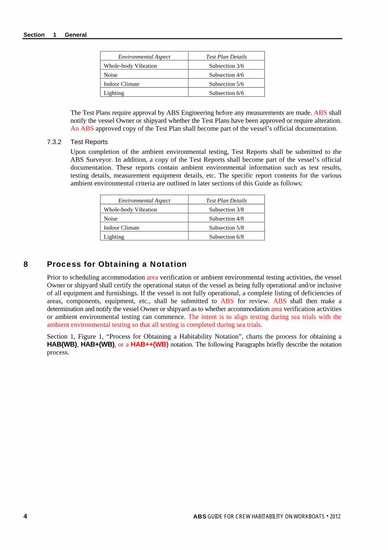
7.3.1 Test Plans Test Plans shall serve as the principal means for verifying the measurements for the ambient environmental aspects of habitability. Separate Test Plans are required for whole-body vibration, noise, indoor climate, and lighting. Specific Test Plan details for the various ambient environmental criteria are outlined in later sections of this Guide as follows:
Section 1 General
4 ABS GUIDE FOR CREW HABITABILITY ON WORKBOATS . 2012
Environmental Aspect Test Plan Details Whole-body Vibration Subsection 3/6 Noise Subsection 4/6 Indoor Climate Subsection 5/6 Lighting Subsection 6/6
The Test Plans require approval by ABS Engineering before any measurements are made. ABS shall notify the vessel Owner or shipyard whether the Test Plans have been approved or require alteration. An ABS approved copy of the Test Plan shall become part of the vessel’s official documentation.
7.3.2 Test Reports Upon completion of the ambient environmental testing, Test Reports shall be submitted to the ABS Surveyor. In addition, a copy of the Test Reports shall become part of the vessel’s official documentation. These reports contain ambient environmental information such as test results, testing details, measurement equipment details, etc. The specific report contents for the various ambient environmental criteria are outlined in later sections of this Guide as follows:
Environmental Aspect Test Plan Details Whole-body Vibration Subsection 3/8 Noise Subsection 4/8 Indoor Climate Subsection 5/8 Lighting Subsection 6/8
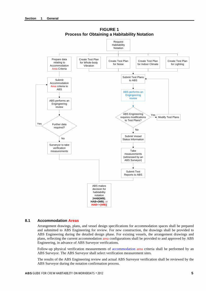
8 Process for Obtaining a Notation Prior to scheduling accommodation area verification or ambient environmental testing activities, the vessel Owner or shipyard shall certify the operational status of the vessel as being fully operational and/or inclusive of all equipment and furnishings. If the vessel is not fully operational, a complete listing of deficiencies of areas, components, equipment, etc., shall be submitted to ABS for review. ABS shall then make a determination and notify the vessel Owner or shipyard as to whether accommodation area verification activities or ambient environmental testing can commence. The intent is to align testing during sea trials with the ambient environmental testing so that all testing is completed during sea trials.
Section 1, Figure 1, “Process for Obtaining a Habitability Notation”, charts the process for obtaining a HAB(WB), HAB+(WB), or a HAB++(WB) notation. The following Paragraphs briefly describe the notation process.
Section 1 General
ABS GUIDE FOR CREW HABITABILITY ON WORKBOATS . 2012 5
FIGURE 1 Process for Obtaining a Habitability Notation
Request Habitability
Notation
Create Test Plan for Indoor Climate
Create Test Plan for Noise
Create Test Plan for Whole-body
Vibration
Create Test Plan for Lighting
Prepare data relating to
Accommodation Area Criteria
Submit Accommodation Area criteria to
ABS
ABS performs an Engingeering
review
Submit Test Plans to ABS
ABS Engineering requires modifications
to Test Plans?Modify Test Plans
Further data required?
Yes
No
Yes
No
Surveryor to take verification
measurements
Submit Vessel Status Information
Take measurements
(witnessed by an ABS Surveyor)
Submit Test Reports to ABS
ABS makes decision for habitability
notation [HAB(WB),
HAB+(WB), or HAB++(WB)]
ABS performs an Engingeering
review
8.1 Accommodation Areas Arrangement drawings, plans, and vessel design specifications for accommodation spaces shall be prepared and submitted to ABS Engineering for review. For new construction, the drawings shall be provided to ABS Engineering during the detailed design phase. For existing vessels, the arrangement drawings and plans, reflecting the current accommodation area configurations shall be provided to and approved by ABS Engineering, in advance of ABS Surveyor verifications.
Follow-up physical verification measurements of accommodation area criteria shall be performed by an ABS Surveyor. The ABS Surveyor shall select verification measurement sites.
The results of the ABS Engineering review and actual ABS Surveyor verification shall be reviewed by the ABS Surveyor during the notation confirmation process.
Section 1 General
6 ABS GUIDE FOR CREW HABITABILITY ON WORKBOATS . 2012
8.2 Ambient Environment Ambient environmental Test Plans for whole-body vibration, noise, indoor climate, and lighting shall be prepared and submitted to ABS Engineering. These Test Plans shall serve as a primary vehicle for verifying the measurement locations and measurement process, as well as specifying the Testing Specialist who will perform the ambient environmental testing.
Testing, inspections, and data collection shall be performed by the Testing Specialist and witnessed by an ABS Surveyor. Test Reports for ambient environmental testing shall be prepared by the Testing Specialist and submitted to the ABS Surveyor for review.
8.3 Results The ABS Engineering accommodation area assessment, ABS Surveyor verification measurements, and ambient environmental Test Reports shall be reviewed by the ABS Surveyor for determination of notation confirmation.
9 Initial Requirements The initial process for obtaining any workboat Habitability notation shall comprise ABS Engineering reviews, ambient environmental testing, and ABS Surveyor verifications. Testing shall be in accordance with the submitted Test Plans reviewed and approved by ABS Engineering in advance of the testing. Testing shall be witnessed by an ABS Surveyor. If the criteria specified in this Guide have been met, then the appropriate notation may be confirmed.
10 Surveys after Construction It is intended that all surveys after construction are to be aligned with Classification Surveys. Harmonization of surveys is to be carried out at the first available opportunity.
10.1 Annual Surveys In order to maintain the HAB(WB), HAB+(WB), or HAB++(WB) notation, an Annual Survey shall be made within three (3) months before or after each annual anniversary date of the crediting of the Initial Survey or the previous Special Periodical Survey. The following information shall be reviewed by the attending ABS Surveyor for issues that could affect the workboat Habitability notation.
i) Collision and grounding reports since previous Initial, Annual or Special Periodical Survey
ii) Fire, repair, and damage reports since previous Initial, Annual or Special Periodical Survey
iii) A list of all structural or mechanical modifications to the vessel since previous Initial, Annual or Special Periodical Survey
iv) Verification that equipment and facilities continue to be fit for purpose and are operating in accordance with accommodation area criteria stated within this Guide
During the attending ABS Surveyor’s review of the submitted information, a determination will be made as to whether changes or alterations have taken place that could affect the workboat Habitability notation. As a result, the vessel may be subject to the review, ambient environmental testing, and inspection requirements of this Guide.
10.2 Special Periodical Surveys In order to maintain the HAB(WB), HAB+(WB), or HAB++(WB) notation, a Special Periodical Survey shall be completed within five (5) years after the date of build or after the crediting date of the previous Special Periodical Survey. A Special Periodical Survey will be credited as of the completion date of the survey but not later than five (5) years from date of build or from the date recorded for the previous Special Periodical Survey. If the Special Periodical Survey is completed within three (3) months prior to the due date, the Special Periodical Survey will be credited to agree with the effective due date. The Special Periodical Survey may be commenced fifteen (15) months prior to the due date and be continued with completion by the due date.
Section 1 General
ABS GUIDE FOR CREW HABITABILITY ON WORKBOATS . 2012 7
10.2.1 Survey Requirements The Survey shall comprise ABS Engineering reviews, ABS Surveyor verifications, and ambient environmental testing. The Survey will cover all five (5) habitability aspects.
The following shall be submitted to ABS three (3) months prior to carrying out the ambient environmental testing:
i) Fire, repair, or damage reports since previous Annual Survey
ii) A list of all structural or mechanical modifications to the vessel since previous Annual Survey
iii) Drawings/arrangements of seafarer spaces, HVAC, electrical, etc., affected by alterations
iv) Copy of approved Initial Test Plans and Test Reports
v) Test Plans and Test Reports resulting from Annual Surveys
vi) Previous Special Periodical Survey Test Plans and Reports, if applicable
vii) Proposed Special Periodical Survey Test Plans for the current survey
The Special Periodical Survey data submittal serves three purposes. The first is to perform an ABS Engineering review of seafarer spaces against any alterations to the vessel since the Initial Survey, with measurements verified by an ABS Surveyor. The second purpose is to provide a history of ambient environmental testing, as well as the Special Periodical Survey ambient environmental Test Plans for review and approval. The third is to allow scheduling of measurement verifications and ambient environmental testing.
A Special Periodical Survey Test Plan for each ambient environmental aspect of Habitability shall be submitted in accordance with the criteria stated below. The approved Initial Test Plans should be used as a basis for creating the Special Periodical Survey Test Plans.
For creation of the Special Periodical Survey Test Plans, Subsection 6, “Test Plan”, and Subsection 7, “Test Requirements”, of this Guide specify the requirements for each ambient environmental aspect (i.e., 3/6, 3/7, 4/6, 4/7, etc.). For specifying measurement locations for the Special Periodical Survey Test Plans, the following changes to 7.4.1, “Selection of Spaces where Measurements are to be Conducted”, of each ambient environmental aspect of Habitability shall be followed:
i) Measurements shall be taken in all areas affected by vessel alterations. Measurements are limited to the ambient environmental aspect affected by the alteration. For example, structural changes require both whole-body vibration and noise measurements. Structural changes do not necessarily require indoor climate or lighting measurements. Changes to luminaires require lighting measurements but not whole-body vibration, noise, or indoor climate measurements.
ii) For all ambient environmental aspects, measurements shall be taken in all worst case or problem area locations based on the requirements set forth in 7.4.1, “Selection of Spaces where Measurements are to be Conducted”, of the appropriate Section of this Guide. [For example, worst case for whole-body vibration is described in 3/7.4.1i)].
iii) For all ambient environmental aspects, measurements shall be taken in twenty-five (25) percent of crew cabins and staterooms identified in the initial Test Plans. The cabin locations must be representative of locations port, starboard, fore, amidships, and aft. Any worst case locations can be considered part of the representative sample for crew cabins and staterooms, if applicable.
iv) For all ambient environmental aspects, measurements shall be taken where a single instance of one (1) type of a manned space exists within the vessel (e.g., bridge, radio room, officer’s mess, gymnasium, library, etc.). The worst case locations can be considered part of the single instance representative sample, if applicable.
v) Where multiple instances of the same type space exist, a representative sample of at least twenty-five (25) percent of each type shall be selected for measurement for all ambient environmental aspects. The worst case locations are to be considered part of the representative sample, if applicable.
Section 1 General
8 ABS GUIDE FOR CREW HABITABILITY ON WORKBOATS . 2012
For all ambient environmental conditions, visual/walk-through inspections shall be conducted in accordance with 7.4.2 of the appropriate Section of this Guide.
10.3 Requirements for Vessel Alterations No alterations which affect or may affect the workboat Habitability notation awarded, including alterations to the structure, machinery, electrical systems, piping, furnishings or lighting systems, are to be made to the vessel unless plans of the proposed alterations are submitted to and approved by ABS before the work of alteration is commenced. If ABS determines that the alteration will affect the workboat Habitability notation, the altered vessel may be subject to the review, verification, and ambient environmental testing requirements of this Guide.
11 Alternatives
11.1 General ABS will consider alternative arrangements, criteria and procedures, which can be shown to meet the criteria directly cited or referred to in this Guide. The demonstration of an alternative’s acceptability can be made through either the presentation of satisfactory service experience or systematic analysis based on valid engineering principles.
11.2 National Regulations ABS will consider for its acceptance alternative arrangements and details which can be shown to comply with standards recognized in the country (flag State) in which the vessel is registered or built, provided they are deemed not less effective.
11.3 Departures from Criteria The criteria contained in this Guide are envisioned to apply to vessels that are engaged in the usual trades and services expected of such vessels, within the scope of the following:
• ABS Rules for Building and Classing Steel Vessels
• ABS Rules for Building and Classing Steel Vessels Under 90 meters in Length (Part 5)
• ABS Rules for Building and Classing Steel Vessels for Service on Rivers and Intracoastal Waterways.
• ABS Rules for Materials and Welding
• ABS Rules for Building and Classing Offshore Support Vessels
It is recognized that unusual or unforeseen conditions may lead to a case where one or more of the parameters of interest in granting a notation may temporarily fall outside the range of acceptability.
When a departure from criteria is identified, during either the notation’s initial issuance or reconfirmation process, it shall be reviewed by ABS in consultation with the Owner. When the design of the accommodation areas or ambient environmental test results contain departures from the stated criteria, these will be subject to special consideration upon the receipt of details about the departure. Depending on the degree and consequences of the departure, the shipyard or Owner may be required to provide an assessment and remediation plan to obtain or maintain the notation. Failure to complete the agreed remediation by the due date will lead to withdrawal of the notation.
ABS GUIDE FOR CREW HABITABILITY ON WORKBOATS . 2012 9
S e c t i o n 2 : A c c o m m o d a t i o n A r e a s
S E C T I O N 2 Accommodation Areas
1 Background To promote maritime safety, efficiency, and habitability, it is important that seafarers maintain appropriate levels of mental and physical fitness while onboard vessels. To help accomplish this, seafarers should be provided with suitable accommodation areas. Appropriate accommodation area design helps promote reliable performance by reducing the potential for fatigue and human error. Appropriate accommodation areas may also enhance morale, recruiting, retention, comfort, and overall quality of life at sea.
Conversely, inappropriate accommodation areas can adversely impact a seafarer’s ability to reliably perform assigned duties, fully relax, sleep, and recover from mentally and physically demanding work activities. This in turn can impact their ability to carry out duties on succeeding watches with the required diligence, accuracy, and attention to safety procedures. Providing an onboard environment that increases seafarer alertness and well-being should be of concern to vessel Owners.
2 Scope This Section and Appendix 3, “Accommodation Area Criteria”, provide the measurement criteria for accommodation spaces. In particular, Appendix 3 encompasses criteria for access and egress, as well as Crew Cabins, sanitary spaces, offices, food services, recreation areas, laundry, and medical spaces. The criteria were selected to help increase crew member safety, productivity, quality of work, retention, and morale. Note: The criteria for access/egress are applicable only to the crew accommodation block, and do not include crew member
work spaces outside of the accommodation block.
Compliance with this Section and Appendix 3 “Accommodation Area Criteria” is a prerequisite for the workboat Habitability (HAB(WB)), workboat Habitability Plus (HAB+(WB)), or workboat Habitability Plus Plus (HAB++(WB)) notation confirmation.
3 Terminology Accommodation Areas/Accommodation Block: Vessel areas where the primary purpose is to rest and recreate. Accommodation spaces include cabins and staterooms, medical facilities (sick bays), offices, recreation rooms, and manned spaces within the accommodation block such as the bridge or control room. For the purposes of this Guide, accommodation areas also include service spaces such as mess rooms, laundry, and storerooms.
4 Associated Documentation • Appendix 3, “Accommodation Area Criteria”
• International Labor Organization (ILO) Conventions 92 and 133 and the ILO MLC, Title 3, 2006
Section 2 Accommodation Areas
10 ABS GUIDE FOR CREW HABITABILITY ON WORKBOATS . 2012
5 Criteria (1 September 2013) The accommodation area criteria are contained in Appendix 3, “Accommodation Area Criteria”. The ILO MLC, 2006 quantitative accommodation area requirements have been included in this Guide and are denoted by a “#” symbol in the tables of Appendix 3 “Accommodation Area Criteria”.
Please note that flag States may have different accommodation area requirements from those presented in this Guide. If the flag State’s requirements are more stringent, they take precedence. If this Guide’s criteria are more stringent, this Guide takes precedence.
The HAB+(WB) and HAB++(WB) notations have more stringent criteria than the HAB(WB) notation with the objective of providing enhanced living and working conditions to improve seafarer safety and comfort. This includes enhanced criteria for work space design, crew cabins, and recreation/leisure areas.
The HAB+(WB) notation requires meeting the accommodation area criteria of HAB(WB) and HAB+(WB). To achieve a HAB++(WB) notation requires meeting the criteria for both HAB(WB) and HAB+(WB), as well as the HAB++(WB) requirements. For example, Criteria #14 below provides three degrees for angles of inclination for stairways, one for HAB(WB), HAB+(WB), and HAB++(WB). If seeking a HAB++(WB) notation, the 40 degrees criteria would need to be fulfilled. By fulfilling the criteria for the HAB++(WB) requirements, the criteria for HAB+(WB) and HAB(WB) are met.
Requirement # = Related ILO MLC 2006, Title 3 Requirement
Meets HAB(WB)
Requirements
Meets HAB+(WB) Requirements
Meets HAB++(WB) Requirements
14 Accommodation area stairways have a maximum angle of inclination from the horizontal of:
• 50 degrees • 45 degrees • 40 degrees
6 Accommodation Area Documentation As stated in 1/7.2, “Accommodation Areas”, accommodation area documentation shall be prepared and submitted to ABS Engineering for review. Confirmatory verification measurements shall be performed by an ABS Surveyor. The following data shall be submitted to ABS Engineering:
6.1 Data Requirements The submitted data shall serve as a means for verifying that the vessel meets the Accommodation Area criteria specified in Appendix 3, “Accommodation Area Criteria”.
6.1.1 New Construction For new construction, scaled arrangement drawings of the accommodation spaces (elevation and plan views), details of the accommodation area outfitting and vessel’s design specification in relation to the accommodation spaces shall be submitted to ABS Engineering.
6.1.2 Existing Vessels For existing vessels, appropriate arrangement drawings and plans reflecting the current accommodation area configurations shall be provided to ABS Engineering along with any current vessel accommodation area design specifications.
Section 2 Accommodation Areas
ABS GUIDE FOR CREW HABITABILITY ON WORKBOATS . 2012 11
7 Submittal Review and Verification Arrangement drawings, plans, and vessel specifications for the accommodation areas shall be prepared and submitted for review by ABS Engineering. For new construction, the drawings shall be provided to ABS Engineering during the detailed design phase. For existing vessels, the arrangement drawings and plans reflecting the current accommodation area configurations shall be provided to ABS Engineering in advance of onboard ABS Surveyor verifications.
ABS Engineering shall review the submitted accommodation area documentation. ABS Engineering shall report any deviation from criteria to the Owner/shipyard for resolution and shall also identify any criteria that the ABS Surveyors must field verify.
The ABS Surveyor shall verify that the submitted drawings match the constructed vessel. The ABS Surveyor shall also verify any criteria that are outstanding from the ABS Engineering review and document deviations from criteria.
8 Results The results of the ABS Engineering review and the ABS Surveyor verification shall be reviewed by the ABS Surveyor against the appropriate HAB(WB), HAB+(WB), or HAB++(WB) criteria for notation confirmation.
12 ABS GUIDE FOR CREW HABITABILITY ON WORKBOATS . 2012
S e c t i o n 3 : W h o l e - b o d y V i b r a t i o n
S E C T I O N 3 Whole-body Vibration
1 Background Working and/or living onboard vessels imposes a series of generally low-frequency mechanical vibrations, as well as single-impulse shock loads, on the human body.
Low-frequency vibrations are also imposed by vessel motions, which are produced by the various sea states in conjunction with vessel speed. These motions can result in motion sickness, body instability, fatigue, and increased health risk aggravated by shock loads induced by vessel slamming. Vessel slamming may be caused by dynamic impact loads being exerted on the vessel’s bottom or bow flare due to vessel size, speed, and wave conditions.
Higher-frequency vibration influencing comfort is often associated with rotating machinery. The imposition of higher frequency vibrations (about 1 to 80 Hz) induces corresponding motions and forces within the human body, creating discomfort and possibly resulting in degraded performance and health (Griffin, 1990).
2 Scope This Section provides the criteria and methods for assessing whole-body vibration relating to habitability onboard vessels. The criteria were selected to limit potential vibration-related interference with work tasks and to improve crew comfort.
Consideration of the vibration loads imposed on the body is restricted to motions transmitted from surrounding structures to the entire human body through the feet of a standing person in the frequency range 1 to 80 Hertz (Hz). Motions transmitted to the body of a seated or recumbent person have been omitted from this Guide. Due to the provision of resilient or non-rigid surfaces on seats and beds, these surfaces will generally attenuate the transfer of vibration to levels that are lower than those experienced when standing. The motions transmitted through the feet are expected to be the highest vibration levels to which crew will be exposed.
Whole-body vibration limits defined in this Section are based on currently available standards. Compliance with this Section is a prerequisite for the workboat Habitability (HAB(WB)), workboat Habitability Plus (HAB+(WB)), or workboat Habitability Plus Plus (HAB++(WB)) notation confirmation.
3 Terminology Acceleration: The rate of change of velocity over time (i.e., meters-per-second squared, m/s2).
Dynamic Positioning: A system to automatically maintain a workboat’s position and heading by controlling propellers and/or thrusters. Dynamic positioning can maintain a position to a fixed point over the bottom, or in relation to a moving object (such as another vessel). It can also be used to position the vessel at a favorable angle towards wind, waves, and current.
Frequency: The number of complete cycles of a periodic process occurring per unit time. Frequency is expressed in Hertz (Hz) which corresponds to the number of cycles observed-per-second.
Frequency Weighting: A transfer function used to modify a signal according to a required dependence on vibration frequency.
• In human response to vibration, various frequency weightings have been defined in order to reflect known or hypothesized relationships between vibration frequency and human response.
• The frequency weighting used to evaluate whole-body vibration in this Guide is Wm (whole-body) for all three axes (x, y, and z), in accordance with ISO 6954.
Section 3 Whole-body Vibration
ABS GUIDE FOR CREW HABITABILITY ON WORKBOATS . 2012 13
Manned Space: Any space where a seafarer may be present for twenty (20) minutes or longer at one time during normal, routine daily activities. Such spaces would include working or living spaces.
Multi-Axis Acceleration Value: The Multi-Axis Acceleration Value is calculated from the root-sums-of-squares of the weighted RMS acceleration values in each axis (axw, ayw and azw) at the measurement point using the following expression:
aw = 222zwywxw aaa ++
where axw, ayw and azw are the weighted RMS acceleration values measured in the x-, y- and z-axes, respectively.
Multi-Axis Vibration: Mechanical vibration or shock acting in more than one (1) direction simultaneously.
Reference Calibration: Calibration of a measuring instrument conducted by an accredited Testing and Calibration Laboratory with traceability to a national or international standard.
Transit Conditions: Those conditions where the vessel is transitioning (moving) from one location to another.
Vibration: The variation with time of the magnitude of a quantity which is descriptive of the motion or position of a mechanical system, when the magnitude is alternately greater and smaller than some average value.
Weighted Root-Mean-Square Acceleration Value (aw): The weighted root-mean-square (RMS) acceleration, aw, in meters-per-second squared, is defined by the expression:
aw = dttaT
T
w )(1
0
2∫
where aw(t) is the weighted acceleration as a function of time in meters-per-second squared (m/s2) and t is the duration of the measurement in seconds.
Whole-body Vibration: Mechanical vibration (or shock) transmitted to the human body as a whole. Whole-body vibration is often due to the vibration of a surface supporting the body.
4 Associated Documentation The following documents provide details about Test Plan preparation, test measurement procedures and/or test reporting:
• ISO 6954:2000, Mechanical Vibration and Shock – Guidelines for the Measurement, Reporting and Evaluation of Vibration with Regard to Habitability on Passenger and Merchant Ships.
• ISO 2631-2:2003, Mechanical Vibration and Shock – Evaluation of Human Exposure to Whole Body Vibration – Part 2, Vibration in Buildings.
• ISO 8041:2005, Human response to vibration – Measuring instrumentation.
• ISO 5348:1998, Mechanical vibration and shock – Mechanical mounting of accelerometers.
• WMO:1995, Sea State Code.
Further guidance can be found in:
• ISO 2923: 1996, Acoustics – Measurement of noise onboard vessels.
• ISO 20283-2:2008, Mechanical Vibration – Measurement of Vibration on Ships – Part 2: Measurement of Structural Vibration.
Section 3 Whole-body Vibration
14 ABS GUIDE FOR CREW HABITABILITY ON WORKBOATS . 2012
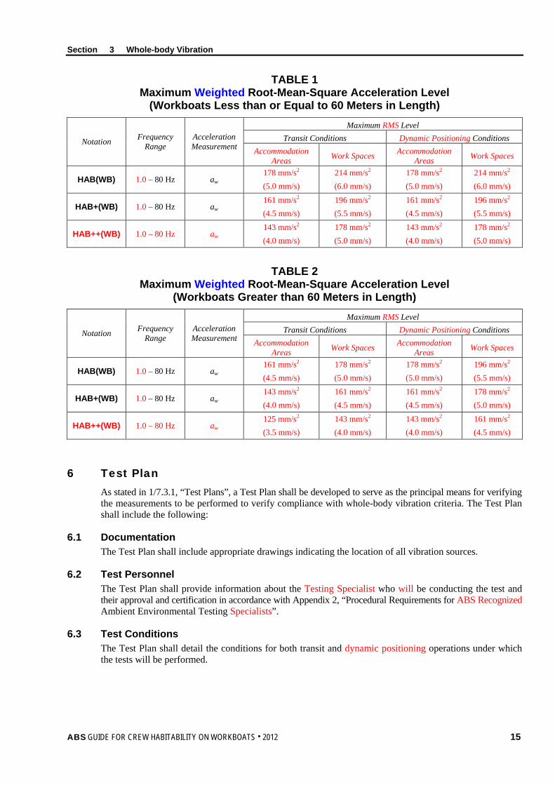
5 Criteria (1 September 2013) The whole-body vibration criteria for the workboat Habitability notations (HAB(WB), HAB+(WB), or HAB++(WB)) are provided in Section 3, Table 1, “Maximum Weighted Root-Mean-Square Acceleration Level (Workboats Less than or Equal to 60 Meters in Length)” and Section 3, Table 2, “Maximum Weighted Root-Mean-Square Acceleration Level (Workboats Greater Than 60 Meters in Length)”. Maximum whole-body vibration levels are provided for transit and dynamic positioning conditions. The severity of the vibration shall be indicated by the weighted root-mean-square acceleration value (aw) as defined in ISO 8041.
Whole-body vibration measurements shall only be taken in manned spaces. A space is considered “manned” if it is occupied by a crew member for twenty (20) minutes or longer at a time for normal, routine daily activities. Specific locations are referred to in 3/7.4, “Measurement Locations”.
The maximum vibration levels for accommodation areas and work spaces in Section 3, Table 1, “Maximum Weighted Root-Mean-Square Acceleration Level (Workboats Less than or Equal to 60 Meters in Length)” and Section 3, Table 2, “Maximum Weighted Root-Mean-Square Acceleration Level (Workboats Greater Than 60 Meters in Length)” shall not be exceeded under normal operating conditions, either in transit or dynamic positioning. The HAB(WB) notation’s maximum vibration level is primarily aimed at reducing discomfort and interference with task performance. The more stringent maximum level for the HAB+(WB) and HAB++(WB) notations are aimed at improving performance and comfort. In this instance, “comfort” means the ability of the crew to use a space for its intended purpose with minimal interference or annoyance from whole-body vibration.
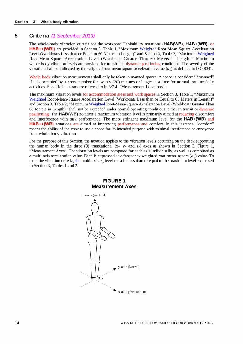
For the purpose of this Section, the notation applies to the vibration levels occurring on the deck supporting the human body in the three (3) translational (x-, y- and z-) axes as shown in Section 3, Figure 1, “Measurement Axes”. The vibration levels are computed for each axis individually, as well as combined as a multi-axis acceleration value. Each is expressed as a frequency weighted root-mean-square (aw) value. To meet the vibration criteria, the multi-axis aw level must be less than or equal to the maximum level expressed in Section 3, Tables 1 and 2.
FIGURE 1 Measurement Axes
z-axis (vertical)
y-axis (lateral)
x-axis (fore and aft)
Section 3 Whole-body Vibration
ABS GUIDE FOR CREW HABITABILITY ON WORKBOATS . 2012 15
TABLE 1 Maximum Weighted Root-Mean-Square Acceleration Level
(Workboats Less than or Equal to 60 Meters in Length)
Notation Frequency Range
Acceleration Measurement
Maximum RMS Level Transit Conditions Dynamic Positioning Conditions
Accommodation Areas Work Spaces Accommodation
Areas Work Spaces
HAB(WB) 1.0 – 80 Hz aw 178 mm/s2 (5.0 mm/s)
214 mm/s2 (6.0 mm/s)
178 mm/s2 (5.0 mm/s)
214 mm/s2 (6.0 mm/s)
HAB+(WB) 1.0 – 80 Hz aw 161 mm/s2 (4.5 mm/s)
196 mm/s2 (5.5 mm/s)
161 mm/s2 (4.5 mm/s)
196 mm/s2 (5.5 mm/s)
HAB++(WB) 1.0 – 80 Hz aw 143 mm/s2 (4.0 mm/s)
178 mm/s2 (5.0 mm/s)
143 mm/s2 (4.0 mm/s)
178 mm/s2 (5.0 mm/s)
TABLE 2 Maximum Weighted Root-Mean-Square Acceleration Level
(Workboats Greater than 60 Meters in Length)
Notation Frequency Range
Acceleration Measurement
Maximum RMS Level Transit Conditions Dynamic Positioning Conditions
Accommodation Areas Work Spaces Accommodation
Areas Work Spaces
HAB(WB) 1.0 – 80 Hz aw 161 mm/s2 (4.5 mm/s)
178 mm/s2 (5.0 mm/s)
178 mm/s2 (5.0 mm/s)
196 mm/s2 (5.5 mm/s)
HAB+(WB) 1.0 – 80 Hz aw 143 mm/s2 (4.0 mm/s)
161 mm/s2 (4.5 mm/s)
161 mm/s2 (4.5 mm/s)
178 mm/s2 (5.0 mm/s)
HAB++(WB) 1.0 – 80 Hz aw 125 mm/s2 (3.5 mm/s)
143 mm/s2 (4.0 mm/s)
143 mm/s2 (4.0 mm/s)
161 mm/s2 (4.5 mm/s)
6 Test Plan As stated in 1/7.3.1, “Test Plans”, a Test Plan shall be developed to serve as the principal means for verifying the measurements to be performed to verify compliance with whole-body vibration criteria. The Test Plan shall include the following:
6.1 Documentation The Test Plan shall include appropriate drawings indicating the location of all vibration sources.
6.2 Test Personnel The Test Plan shall provide information about the Testing Specialist who will be conducting the test and their approval and certification in accordance with Appendix 2, “Procedural Requirements for ABS Recognized Ambient Environmental Testing Specialists”.
6.3 Test Conditions The Test Plan shall detail the conditions for both transit and dynamic positioning operations under which the tests will be performed.
Section 3 Whole-body Vibration
16 ABS GUIDE FOR CREW HABITABILITY ON WORKBOATS . 2012
6.4 Measurement Locations The Test Plan shall document, in detail, on appropriate drawings, all spaces where measurements will be taken. In addition, transducer measurement positions shall be indicated. Details on selecting measurement locations and determining transducer measurement positions are provided in 3/7.4, “Measurement Locations”.
6.5 Data Acquisition and Instruments The Test Plan shall provide information regarding the methods and instrumentation to be used for measurement and data collection. Instrumentation specification details shall include type of instruments to be used, accuracy, calibration, sensitivity, conformance with ISO 8041, and frequency range. More details on data acquisition and instruments are provided in 3/7.2, “Data Acquisition and Instruments”.
6.6 Data Analysis The Test Plan shall provide information regarding the methods, software, and instrumentation to be used for data analysis.
6.7 Test Schedule The Test Plan shall provide information regarding the proposed test schedule.
7 Test Requirements
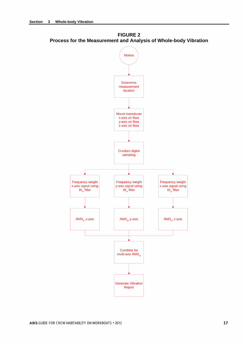
7.1 General Whole-body vibration measurements shall be in accordance with the procedures described in ISO 6954. When the procedures described in this Guide deviate from any requirements or procedures mentioned in ISO 6954, the more stringent requirement shall take precedence.
The relationship between the various factors to be considered when taking whole-body vibration measurements and computing results is illustrated in Section 3, Figure 2, “Process for the Measurement and Analysis of Whole-body Vibration”.
7.2 Data Acquisition and Instruments For the HAB(WB), HAB+(WB), or HAB++(WB) notation, a sample of data shall be recorded for each whole-body vibration measurement position. Each whole-body vibration measurement sample shall be at least sixty (60) seconds in duration. For each location measured, a data sample shall be taken during transit conditions and dynamic positioning conditions, in accordance with the requirements of 3/7.3, “Test Conditions”.
The above measurement samples shall all be taken using the appropriate Type 1 instrumentation (ISO 8041), then frequency weighted and analyzed in accordance with ISO 6954. It is desirable to employ equipment that records and stores acceleration time histories.
Section 3 Whole-body Vibration
ABS GUIDE FOR CREW HABITABILITY ON WORKBOATS . 2012 17
FIGURE 2 Process for the Measurement and Analysis of Whole-body Vibration
Determinemeasurement
location
Motion
Mount transducerx-axis on floory-axis on floorz-axis on floor
Conduct digitalsampling
Frequency weighty-axis signal using
Wm filter
Frequency weightx-axis signal using
Wm filter
Frequency weightz-axis signal using
Wm filter
RMSw y-axisRMSw x-axis RMSw z-axis
Combine formulti-axis RMSw
Generate VibrationReport
Section 3 Whole-body Vibration
18 ABS GUIDE FOR CREW HABITABILITY ON WORKBOATS . 2012
7.3 Test Conditions The test conditions required for the whole-body vibration measurements shall be in accordance with each of the following Subparagraphs.
7.3.1 Power Output i) Transit: The propulsion machinery shall run at contractual service conditions.
ii) Dynamic Positioning: Devices such as azimuth or tunnel thrusters automatic or manual shall run at contractual service conditions.
7.3.2 Equipment Operation As appropriate for the mode of operation (transit or dynamic positioning), all machinery essential for vessel operation shall operate under normal conditions throughout the measurement period. Heating, Ventilation, and Air Conditioning (HVAC) systems are to be running as for normal seagoing conditions during the whole-body vibration measurements.
7.3.3 Course and Water Depth Whole-body vibration measurements are to be taken with the vessel in a depth of water not less than five (5) times the draft of the vessel. For vessels that do not operate in water depths of five (5) times draft, measurements shall be taken under normal operating and transit conditions. The vessel shall maintain a single heading and a constant speed during the test. Measurements during dynamic positioning shall be taken while the vessel is maintaining a position relative to another vessel or fixed point (e.g., offshore installation).
7.3.4 Rudder Conditions During transit measurements, rudder action shall be minimized. During dynamic positioning, measurements shall be taken while the vessel is maintaining a position relative to another vessel or fixed point (e.g., offshore installation).
7.3.5 Sea Conditions Measurements are to be taken under conditions of Sea State 3 or less, as defined by the World Meteorological Organization (WMO) (1995) Sea State Code.
7.3.6 Loading Conditions The loading condition of the workboat shall be as close as possible to normal operating conditions.
7.3.7 Test Interference During the whole-body vibration measurements, vibration arising from every kind of unnecessary human activity shall be avoided. For this reason, only the personnel needed for the normal operation of the equipment in the space and those carrying out the measurements shall be present in the space being tested.
7.4 Measurement Locations 7.4.1 Selection of Spaces where Measurements are to be Conducted
The aim when selecting vibration measurement locations shall be to obtain a representative sample of data that reflects the actual conditions in manned spaces. For practical reasons, it is important to select the locations such that an appropriate amount of sample data can be collected during the testing phase. The measurement locations shall be selected in accordance with the following criteria:
i) Select potential worst case locations based on their proximity to vibration emitting sources such as propulsion or other rotating machinery or where vibration is likely to be transmitted to manned spaces, accommodation areas and recreation areas via the vessel’s structure. Measurements shall be taken in all identified worst case locations (e.g., cabin adjacent to a machinery space).
ii) Where a single instance of one (1) type of manned space exists within the vessel (e.g., bridge, mess room, gymnasium, library, etc.), that location shall be selected for measurement.
Section 3 Whole-body Vibration
ABS GUIDE FOR CREW HABITABILITY ON WORKBOATS . 2012 19
iii) Select a representative sample of crew cabins and staterooms throughout the vessel. For vessels with less than 20 cabins, fifty (50) percent of cabins on each deck shall be selected. For vessels with greater than 20 cabins, thirty (30) percent of cabins on each deck shall be selected. These measurement locations must be selected at locations port, starboard, fore, amidships and aft. The worst case locations can be considered part of the representative sample for crew cabins and staterooms, if applicable.
iv) Where multiple instances of the same type accommodation space exist that are not crew cabins, a representative sample of at least fifty (50) percent of each type shall be selected for measurement. The worst case locations are to be considered part of the representative sample, if applicable.
7.4.2 Walkthrough Verification Inspection Locations All normally manned spaces shall be subject to a walkthrough inspection by the ABS Surveyor. The number and locations of the walkthrough inspections will be determined by the ABS Surveyor. The purpose of the walkthrough verification is to subjectively assess the vibration qualities. At the discretion of the ABS Surveyor, additional measurements may be required.
7.4.3 Transducer Measurement Positions Vibration transducers (accelerometers) shall be located and attached properly to the floor surface to measure the vibration at the interface between the standing crew member and the source of vibration. The mounting of accelerometers shall comply with ISO 5384. When the vibration enters the human body from a non-rigid or resilient material (e.g., floor covering), secure the transducers with a suitably formed mount that does not alter the pressure distribution on the surface of the floor covering.
In cabins or staterooms, the vibration transducers shall be placed on the deck in the center of the space. (Note: This location may not provide the maximum vibration levels for this particular space. The objective is to minimize the number of measurements yet still obtain a fair and representative sample of the exposure conditions of the person occupying the cabin or stateroom).
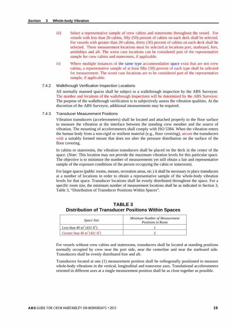
For larger spaces (public rooms, messes, recreation areas, etc.) it shall be necessary to place transducers at a number of locations in order to obtain a representative sample of the whole-body vibration levels for that space. Transducer locations shall be evenly distributed throughout the space. For a specific room size, the minimum number of measurement locations shall be as indicated in Section 3, Table 3, “Distribution of Transducer Positions Within Spaces”.
TABLE 3 Distribution of Transducer Positions Within Spaces
Space Size Minimum Number of Measurement Positions in Room
Less than 40 m2 (431 ft2) 1 Greater than 40 m2 (431 ft2) 2
For vessels without crew cabins and staterooms, transducers shall be located at standing positions normally occupied by crew near the port side, near the centerline and near the starboard side. Transducers shall be evenly distributed fore and aft.
Transducers located at one (1) measurement position shall be orthogonally positioned to measure whole-body vibrations in the vertical, longitudinal and transverse axes. Translational accelerometers oriented in different axes at a single measurement position shall be as close together as possible.
Section 3 Whole-body Vibration
20 ABS GUIDE FOR CREW HABITABILITY ON WORKBOATS . 2012
8 Test Report As stated in 1/7.3.2, “Test Reports”, a Test Report shall be submitted to the ABS Surveyor to determine whether the vibration levels meet the whole-body vibration criteria and whether this part of the notation requirement has been met. The details listed in the following paragraphs shall be provided in the Whole-body Vibration Test Report.
8.1 Test Details The following details shall be recorded for each period of testing:
i) Loading (mean draft and trim)
ii) Number of crew and other persons onboard during tests
iii) Bridge confirmation that operating conditions complied with contractual service conditions
iv) What class of Dynamic Positioning (e.g., DP-0, DP-1, etc.)
v) Vessel course and speed, as well as latitude and longitude coordinates of tests
vi) Average water depth under keel
vii) Weather conditions and meteorological data (i.e., wind speed and direction, ambient outdoor air temperature, outdoor humidity, barometric pressure) at the onset of every data collection period and at intervals of every four (4) hours (if needed) during any data collection period. Weather conditions shall also be reported at the end of each data collection period.
viii) Sea state
ix) Direction of swell relative to vessel heading
x) Any indications of abnormal activity during the test that might skew results
xi) Vessel equipment operated during the test
8.2 Transducer Measurement Positions Actual transducer positions within the measured spaces (for both transit and dynamically positioned operations) shall be indicated on appropriate drawings.
8.3 Measurement Equipment Details Details of measurement and analysis equipment (e.g., manufacturer, type and serial number, accuracy and resolution), including frequency analysis parameters (e.g., resolution, averaging time, and filtering), shall be provided.
Copies of the relevant instrumentation reference calibration certificates, together with the results of field setup and calibration checks before and after the field tests, shall be provided.
8.4 Results The following results, per sample period and measurement axis, as appropriate for notation, shall be provided in table format (for both transit and dynamic positioning operations):
i) Measurement position (i.e., space and location within space)
ii) Measurement period if different from requirements
iii) Sample number
iv) Multi-Axis weighted RMS values
v) Equipment operating in proximity to the measurement position
Section 3 Whole-body Vibration
ABS GUIDE FOR CREW HABITABILITY ON WORKBOATS . 2012 21
For all the remaining spaces that were checked through walkthrough verification inspection and spot check measurements, the following information shall be provided:
i) Name and number of spaces
ii) Walkthrough inspection observations
iii) Measurement results, if necessary
8.5 Deviations All deviations from the approved Test Plan shall be reported.
8.6 Surveyor Witnessing Documentation The equipment calibration and data collection process of vibration tests conducted at sea shall be witnessed by an ABS Surveyor. The ABS Surveyor shall provide documentation stating whether all steps of the vibration testing were completed to their satisfaction. A copy of the witnessing document shall be given to the person conducting the onboard testing for insertion into the final Whole-body Vibration Test Report. The original shall be retained for ABS’ files.
9 Results The Whole-body Vibration Test Report shall be reviewed by the ABS Surveyor against the appropriate HAB(WB), HAB+(WB), or HAB++(WB) criteria for notation confirmation.
22 ABS GUIDE FOR CREW HABITABILITY ON WORKBOATS . 2012
S e c t i o n 4 : N o i s e
S E C T I O N 4 Noise
1 Background A large amount of research has been performed on the effects of noise on humans. Established or commonly used criteria exist for the effects of noise on speech communication, hearing loss, sleep, concentration, and “annoyance”. These have provided a basis for the criteria in this Guide.
A detailed discussion of the effects of noise on human performance, health, and comfort is found in Kryter (1994) The Handbook of Hearing and the Effects of Noise: Physiology, Psychology and Public Health.
2 Scope In this Section, noise criteria have been selected to improve crew performance and to facilitate communication and sleep in appropriate vessel spaces. An additional goal is to enhance crew safety and comfort. In this instance, “comfort” means the ability of the crew to use a space for its intended purpose with minimal interference or annoyance from noise.
The noise criteria presented in this Section are lower than the levels commonly associated with hearing loss. Further guidance with respect to hearing conservation is provided in the IMO Resolution A.468(XII) (1981) Code on Noise Levels On-board Ships and should be followed for noise levels and exposure duration, particularly for areas with noise levels in excess of 85 dB(A).
This Section applies to manned spaces and other areas occupied by seafarers for twenty (20) minutes or longer at any one time during normal, routine daily activities. Examples of such spaces include cabins, staterooms, work spaces (duty stations), mess areas, and recreation spaces, both inside and in other vessel locations outside the accommodation block.
Compliance with this Section is a prerequisite for the workboat Habitability (HAB(WB)), workboat Habitability Plus (HAB+(WB)), or workboat Habitability Plus Plus (HAB++(WB)) notation confirmation.
3 Terminology A-weighted Sound Pressure Level: The magnitude of a sound, expressed in decibels (i.e., 20 micropascals); the various frequency components are adjusted according to the A-weighted values given in IEC 61672-1 (2004) in order to account for the frequency response characteristics of the human ear. The symbol is LA; the unit is dB(A). The measurement LAeq is an equivalent continuous A-weighted sound pressure level, measured over a period of time.
Calibration Checks: Field calibration of a measuring instrument conducted before and after a field test, using a reference calibrated signal or through zero calibration.
Dynamic Positioning: A system to automatically maintain a workboat’s position and heading by controlling propellers and/or thrusters. Dynamic positioning can maintain a position to a fixed point over the bottom, or in relation to a moving object (such as another vessel). It can also be used to position the vessel at a favorable angle towards wind, waves, and current.
Equivalent Continuous A-weighted Sound Pressure Level: The A-weighted sound pressure level of a notional steady sound, over a certain time interval, which would have the same acoustic energy as the variable-loudness real sound under consideration, over that same time interval. The symbol is LAeq; the unit is dB(A).
Reference Calibration: Calibration of measuring instrument, conducted by an accredited Testing and Calibration Laboratory, with traceability to a national or international standard.
Transit Conditions: Those conditions where the vessel is transitioning (moving) from one location to another.
Section 4 Noise
ABS GUIDE FOR CREW HABITABILITY ON WORKBOATS . 2012 23
4 Associated Documentation The following documents provide details about Test Plan preparation, test measurement procedures and/or test reporting:
• ISO 2923:1996, Acoustics – Measurement of noise onboard vessels
• IEC 61672-1:2004, Electroacoustics – Sound Level Meters – Part 1: Specifications IEC 61672-1 (2004)
• IMO Resolution A.468(XII):1981, Code on noise levels onboard ships.
• WMO:1995, Sea State Code.
5 Criteria
5.1 Equivalent Continuous A-weighted Sound Pressure Level (1 September 2013) The noise criteria for the workboat Habitability notations (HAB(WB), HAB+(WB), and HAB++(WB)) are provided in Section 4, Table 1, “Noise Criteria for Workboats”.
Noise levels shall be determined for the test conditions specified in 4/7.3, “Test Conditions” and shall not exceed the maximum acceptable LAeq levels indicated in Section 4, Table 1, “Noise Criteria for Workboats”, for each type of space or area. The maximum acceptable noise levels given in Section 4, Table 1, “Noise Criteria for Workboats” are LAeq values, determined as appropriate to the character of the noise (see 4/7.5, “Measurement Procedures and Recorded Results”). These limit values are for transit and dynamic positioning operations and do not include any in-port activities.
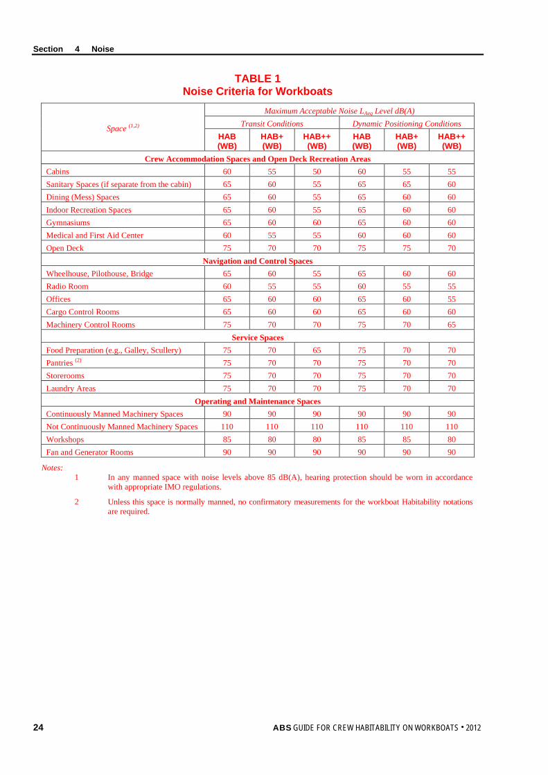
Section 4 Noise
24 ABS GUIDE FOR CREW HABITABILITY ON WORKBOATS . 2012
TABLE 1 Noise Criteria for Workboats
Space (1,2)
Maximum Acceptable Noise LAeq Level dB(A) Transit Conditions Dynamic Positioning Conditions
HAB (WB)
HAB+ (WB)
HAB++ (WB)
HAB (WB)
HAB+ (WB)
HAB++ (WB)
Crew Accommodation Spaces and Open Deck Recreation Areas Cabins 60 55 50 60 55 55 Sanitary Spaces (if separate from the cabin) 65 60 55 65 65 60 Dining (Mess) Spaces 65 60 55 65 60 60 Indoor Recreation Spaces 65 60 55 65 60 60 Gymnasiums 65 60 60 65 60 60 Medical and First Aid Center 60 55 55 60 60 60 Open Deck 75 70 70 75 75 70
Navigation and Control Spaces Wheelhouse, Pilothouse, Bridge 65 60 55 65 60 60 Radio Room 60 55 55 60 55 55 Offices 65 60 60 65 60 55 Cargo Control Rooms 65 60 60 65 60 60 Machinery Control Rooms 75 70 70 75 70 65
Service Spaces Food Preparation (e.g., Galley, Scullery) 75 70 65 75 70 70 Pantries (2) 75 70 70 75 70 70 Storerooms 75 70 70 75 70 70 Laundry Areas 75 70 70 75 70 70
Operating and Maintenance Spaces Continuously Manned Machinery Spaces 90 90 90 90 90 90 Not Continuously Manned Machinery Spaces 110 110 110 110 110 110 Workshops 85 80 80 85 85 80 Fan and Generator Rooms 90 90 90 90 90 90
Notes: 1 In any manned space with noise levels above 85 dB(A), hearing protection should be worn in accordance
with appropriate IMO regulations.
2 Unless this space is normally manned, no confirmatory measurements for the workboat Habitability notations are required.
Section 4 Noise
ABS GUIDE FOR CREW HABITABILITY ON WORKBOATS . 2012 25
6 Test Plan As stated in 1/7.3.1, “Test Plans”, a Test Plan shall be developed to serve as the principal means for verifying the measurements to be performed to demonstrate or confirm compliance with noise criteria. The Test Plan shall include the following:
6.1 Documentation The Test Plan shall include appropriate design information including noise specifications for the vessel. It shall also include layout drawings indicating the locations of all noise sources and noise generating equipment. The information shall be of such detail to enable an ABS Surveyor to verify compliance with the criteria set in this Guide.
The Test Plan shall be submitted to ABS Engineering for review and approval.
6.2 Test Personnel The Test Plan shall provide information about the Testing Specialist who will be conducting the test and their approval and certification in accordance with Appendix 2, “Procedural Requirements for ABS Recognized Ambient Environmental Testing Specialists”.
6.3 Test Conditions Measurements are to be taken under conditions of Sea State 3 or less, as defined by the World Meteorological Organization (WMO) (1995) Sea State Code.
6.4 Measurement Locations The Test Plan shall document, in detail, on appropriate drawings, all spaces or areas where measurements will be taken for both transit and dynamic positioning operations. In addition, measurement positions shall be indicated on the drawings. Details on selecting measurement locations are provided in 4/7.4, “Measurement Locations”.
6.5 Data Acquisition and Instruments The Test Plan shall provide information regarding the methods and instrumentation to be used for measurement and data collection. Instrumentation specification details shall include type of instruments to be used, accuracy, calibration, and sensitivity. More details on data acquisition and instruments are provided in 4/7.2, “Data Acquisition and Instruments”.
6.6 Data Analysis The Test Plan shall provide information regarding the methods, software, and instrumentation to be used for data analysis.
6.7 Test Schedule The Test Plan shall provide information regarding the proposed test schedule.
7 Test Requirements
7.1 General In general, the noise measurements shall be carried out in accordance with the requirements of IMO Resolution A.468(XII) Code on Noise Levels On-board Ships. However, where the IMO requirements differ from those in this Guide, the more stringent requirement shall take precedence.
7.2 Data Acquisition and Instruments The integrating-averaging sound level meter shall meet the requirements for a Type 1 instrument specified in IEC 61672-1.
For each location sampled, a measurement shall be taken for transit and dynamic positioning operations in accordance with the requirements in 4/7.3, “Test Conditions”. It is recommended that dynamic positioning measurements be noted as to whether positioning was maintained dynamically or manually.
Section 4 Noise
26 ABS GUIDE FOR CREW HABITABILITY ON WORKBOATS . 2012
7.3 Test Conditions The test conditions required for the noise measurements shall be in accordance with each of the following Subparagraphs, based on ISO 2923.
7.3.1 Power Output i) Transit: The propulsion machinery shall run at contractual service conditions.
ii) Dynamic Positioning: Devices such as azimuth or tunnel thrusters automatic or manual shall run at contractual service conditions.
7.3.2 Equipment Operation As appropriate for the mode of operation (transit or dynamic positioning), all machinery essential for vessel operation shall operate under normal conditions throughout the measurement period. Heating, Ventilation, and Air Conditioning (HVAC) systems are to be running as for normal seagoing conditions during the noise measurements.
For the galley/scullery, all equipment that runs for twenty (20) minutes or more (e.g., ventilation hoods) should be running during the noise measurements. Equipment that is used only intermittently (e.g., blender/mixer/meat cutter) need not be running during the noise measurements. Note the equipment that is running in the Noise Test Report.
7.3.3 Course and Water Depth For transit mode of operations, noise measurements are to be taken with the vessel in a depth of water not less than five (5) times the draft of the vessel. For vessels that do not operate in water depths of five (5) times draft, measurements shall be taken under normal operating and transit conditions. The course of the vessel shall be as straight as possible and at a constant speed.
7.3.4 Rudder Conditions During transit measurements, rudder action shall be minimized. During dynamic positioning, measurements shall be taken while the vessel is maintaining a position relative to another vessel or fixed point (e.g., offshore installation).
7.3.5 Sea Conditions Measurements are to be taken under conditions of Sea State 3 or less, as defined by the World Meteorological Organization (WMO) (1995) Sea State Code.
7.3.6 Loading Conditions The loading condition of the workboat shall be as close as possible to normal operating conditions.
7.3.7 Test Interference During the noise measurements, noise arising from every kind of unnecessary human activity shall be avoided. For this reason, only the personnel needed for the normal operation of the equipment in the space and those carrying out the measurements shall be present in the space being tested.
Doors and windows shall be closed, except where they are normally left open (such as the door on the lee side of the navigation bridge, which may normally be open). Any open doors or windows shall be noted in the Noise Test Report. Spaces shall be furnished with all usual equipment and furnishings normally found in the space. Equipment shall be configured to operate in its normal operating mode.
Section 4 Noise
ABS GUIDE FOR CREW HABITABILITY ON WORKBOATS . 2012 27
7.4 Measurement Locations 7.4.1 Selection of Spaces where Measurements are to be Conducted
The aim when selecting noise measurement locations shall be to obtain a representative sample of data that reflects the actual conditions in manned spaces. For practical reasons, it is important to select the locations such that an appropriate amount of sample data can be collected during the testing phase. The measurement locations shall be selected in accordance with the following criteria:
i) Select potential worst case locations based on their proximity to noise emitting sources such as propulsion or other rotating machinery or where noise is likely to be transmitted to manned spaces, accommodation areas and recreation areas via the vessel’s structure. Measurements shall be taken in all identified worst case locations (e.g., cabin adjacent to a machinery space).
ii) Where a single instance of one (1) type of manned space exists within the vessel (e.g., bridge, mess room, gymnasium, library, etc.), that location shall be selected for measurement.
iii) Select a representative sample of crew cabins and staterooms throughout the vessel. For vessels with less than 20 cabins, fifty (50) percent of cabins on each deck shall be selected. For vessels with greater than 20 cabins, thirty (30) percent of cabins on each deck shall be selected. These measurement locations must be selected at locations port, starboard, fore, amidships and aft. The worst case locations can be considered part as the representative sample for crew cabins and staterooms, if applicable.
iv) Where multiple instances of the same type accommodation space exist that are not crew cabins, a representative sample of at least fifty (50) percent of each type shall be selected for measurement. The worst case locations are to be considered part of the representative sample, if applicable.
7.4.2 Walkthrough Verification Inspection Locations All normally manned spaces shall be subject to a walkthrough inspection by the ABS Surveyor. The number and locations of the walkthrough inspections will be determined by the ABS Surveyor. The purpose of the walkthrough verification is to subjectively assess the noise qualities. At the discretion of the ABS Surveyor, additional measurements may be required.
7.4.3 Measurement Positions The measurement positions described below are taken or adapted from ISO 2923 and IMO Resolution A.468(XII).
Measure at positions where persons will be seated or standing. The microphone shall be at a height of approximately 1200 mm (47 in.) from the deck to represent seated persons and approximately 1600 mm (63 in.) from the deck to represent standing persons, as appropriate for the measurement position.
In crew accommodation spaces, measure in the middle of the space.
For all measurements, the microphone shall not be closer than 500 mm (20 in.) from the boundary surface (e.g., bulkhead) of a space. The measurement time shall be at least fifteen (15) seconds and shall be long enough to enable the measurement of the equivalent continuous A-weighted sound pressure level for any specified time interval within the stated limits of overall measurement uncertainty.
If practicable, do not measure closer than 1000 mm (39.5 in.) from operating machinery, air inlets, or from decks, bulkheads or other large surfaces. Where this is not possible, measure midway between the machinery and an adjacent reflecting surface.
Section 4 Noise
28 ABS GUIDE FOR CREW HABITABILITY ON WORKBOATS . 2012
7.5 Measurement Procedures and Recorded Results 7.5.1 Persons Present During Measurements
When Testing Specialist personnel are conducting noise level measurements in any space, only crew members necessary for the operation of that space should be present.
7.5.2 Sampling Duration Equivalent continuous A-weighted sound pressure levels (LAeq) shall be reported for each measurement location. The LAeq sampling duration shall be sufficient to achieve a stable reading. Sampling time shall be fifteen (15) seconds or longer.
7.5.3 Cyclic Noise If the noise within a space is cyclic, the LAeq sampling duration shall be sufficient to capture an integer number of complete cycles. If a long-duration sample is judged impractical, an LAeq value shall be determined and reported for the high-noise portion of the cycle.
7.5.4 Intermittent Noise If the noise within a space is present intermittently, an LAeq value shall be determined and reported for a period of high-level noise.
7.5.5 HVAC Related Noise If HVAC system-related noise is a large contributor to the noise level in the space, a noise measurement shall be made approximately 300 mm (12 in.) from the vent, measured in line with the direction of airflow, and recorded in the Noise Test Report.
8 Test Report As stated in 1/7.3.2, “Test Reports”, a Test Report shall be submitted to the ABS Surveyor to determine whether the noise levels are at or below the limits and whether this part of the notation requirement has been met. The details listed in the following paragraphs shall be provided in the Noise Test Report.
8.1 Test Details The following details shall be provided for each period of testing:
i) Loading (mean draft and trim)
ii) Number of crew and number of other persons onboard during testing
iii) Bridge confirmation that operating conditions complied with contractual service conditions
iv) Vessel course and speed
v) Average water depth under keel
vi) Weather conditions and meteorological data (i.e., wind speed and direction, ambient outdoor air temperature, outdoor humidity, barometric pressure) at the onset of every data collection period and at intervals of every four (4) hours (if needed) during any data collection period. Weather conditions shall also be reported at the end of each data collection period.
vii) Sea state
viii) Any indications of abnormal activity during the test that might skew results
ix) Vessel’s equipment operated during the test
8.2 Measurement Positions For transit and dynamic positioning measurements, actual measurement location positions shall be indicated on appropriate drawings.
Section 4 Noise
ABS GUIDE FOR CREW HABITABILITY ON WORKBOATS . 2012 29
8.3 Measurement Equipment Details Details of measurement and analysis equipment (e.g., manufacturer, type and serial number, accuracy, sampling frequency and resolution) shall be provided.
Copies shall be provided of the relevant instrumentation reference calibration certificates, together with the results of field setup and calibration checks, before and after the field tests.
8.4 Results The following results, per measurement location and sample period as appropriate for notation, shall be provided in table format (for transit and dynamic positioning measurements):
i) Measurement position (i.e., space and location within space)
ii) Measurement conditions (transit or dynamic positioning, power output and pitch angles, sea states)
iii) Number of people present in the space at time of measurement
iv) Measurement period
v) Time at start and finish of measurement
vi) Equivalent continuous A-weighted sound pressure level (LAeq)
vii) Note any open doors and windows
viii) Note equipment operating in proximity to the measurement position
ix) Note observed direct sources of noise (such as ventilation devices) and any measurement data collected
For all the remaining spaces that were checked through walkthrough verification inspection and spot check measurements, the following information shall be provided:
i) Name and number of space
ii) Walkthrough inspection observations
iii) Measurement results if necessary
8.5 Deviations All deviations from the approved Test Plan shall be reported.
8.6 Surveyor Witnessing Documentation The equipment calibration and data collection process of the noise level tests shall be witnessed by an ABS Surveyor. The ABS Surveyor shall provide documentation stating whether all steps of the noise level testing were completed to their satisfaction. A copy of the witnessing document shall be given to the person conducting the testing, for insertion into the final Noise Test Report. The original shall be retained for ABS’ files.
9 Results The Noise Test Report and test results shall be reviewed by the ABS Surveyor against the noise criteria for notation confirmation.
30 ABS GUIDE FOR CREW HABITABILITY ON WORKBOATS . 2012
S e c t i o n 5 : I n d o o r C l i m a t e
S E C T I O N 5 Indoor Climate
1 Background Thermal comfort is defined in ISO 7730 as “…that condition of mind which expresses satisfaction with the thermal environment”. The sensation of thermal comfort is therefore largely subjective and will vary from person to person. Due to differences in metabolism and expectations, there are distinct individual differences among people’s perception of comfort as a function of temperature, humidity, and other atmospheric characteristics. Acclimatization, habits, and expectations influence perceived comfort. These individual differences make it difficult to specify a single thermal environment that will be satisfactory to everyone. A thermal environment is therefore typically defined to be acceptable to at least eighty (80) percent of the occupants of an interior space.
Individually, the perception of thermal comfort is largely determined by the interaction of thermal environmental factors such as air temperature, air velocity, relative humidity, and factors related to activity and clothing.
The thermal control or Heating, Ventilation, and Air Conditioning (HVAC) systems on a vessel should be designed to effectively control the indoor thermal environmental parameters to within acceptable limits to facilitate the thermal comfort of the occupants.
2 Scope This Section provides the assessment criteria, verification, and measurement methodology for indoor climate relating to habitability on workboats. The criteria are based on currently available standards and were selected to provide an index of crew thermal comfort.
The thermal environmental variables covered by this Guide include the ambient qualities of air temperature, air velocity, and relative humidity. Vertical thermal gradient is used to indicate uncomfortable temperature differentials between a person’s head and feet. The crew cabin area horizontal gradient temperature differential between the temperature of inside bulkhead surfaces adjacent to crew cabins and the average air temperature within the space serves as an indication of potential thermal comfort or discomfort.
The thermal environmental criteria provided in this Guide are for persons wearing typical indoor clothing occupied with light, primarily sedentary activity and resulting in a thermal environment acceptable to at least eighty (80) percent of the occupants.
This Section applies to enclosed manned spaces occupied by crew members for twenty (20) minutes or longer at any one time for normal, routine daily activities. Examples of seafarer spaces include crew accommodation areas, bridge, engine control room, and indoor work spaces.
Compliance with this Section is a prerequisite for the workboat Habitability (HAB(WB)), workboat Habitability Plus (HAB+(WB)), or workboat Habitability Plus Plus (HAB++(WB)) notation confirmation.
3 Terminology Air Temperature: The temperature of the air surrounding a person, measured with a standard thermometer.
Air Velocity or Movement: The rate of displacement of ambient air in a specific direction in meters-per-second (m/s) or feet-per-second (ft/s).
Comfort Zone: That range of environmental conditions in which at least eighty (80) percent of crew members experience thermal comfort.
Section 5 Indoor Climate
ABS GUIDE FOR CREW HABITABILITY ON WORKBOATS . 2012 31
Horizontal Gradient: The difference between the inside surface temperatures of the bulkheads bounding the berth and the average air temperature within the cabin. This is used as an indication of potential thermal discomfort due to radiant thermal sources within the cabin.
HVAC Zone: A space or group of spaces that is (are) independently controlled for temperature, humidity, and air distribution. A zone usually comprises common duct work fed from an air handler.
Reference Calibration: Calibration of a measuring instrument, conducted by an accredited Testing and Calibration Laboratory, with traceability to a national or international standard.
Relative Humidity (RH): The ratio of the amount of vapor contained in the air (absolute humidity) to the maximum amount of vapor the air can hold at a given temperature before precipitation (condensation) occurs.
Thermal Comfort: Subjective index of “that condition of mind which expresses satisfaction with the thermal environment”.
Ventilation: Ventilation is the process of supplying air to, and removing air from, any space by natural or mechanical means. From the standpoint of comfort and health, ventilation issues involve both quantity and quality.
Vertical Gradient: The vertical air temperature difference within an enclosed space. The vertical gradient is used as an indication of potential local discomfort at the head and feet.
4 Associated Documentation The following documents provide details about Test Plan preparation, test measurement procedures and/or test reporting:
• ANSI/ASHRAE 55a, (2010). Thermal environmental conditions for human occupancy
• ANSI/ASHRAE (15) (2010). Practices for Measuring, Testing, Adjusting, and Balancing Shipboard HVAC&R Systems
• ISO 7726 (E), (1998), Ergonomics of the thermal environment – Instruments for measuring physical quantities
• NEBB, (2005). Procedural standards for testing, adjusting, balancing of environmental Systems.
5 Criteria (1 September 2013) The indoor climate criteria for the workboat Habitability notations (HAB(WB), HAB+(WB), and HAB++(WB)) are provided in Section 5, Table 1, “Summary of Indoor Climate Requirements”.
Indoor climate measurements shall be taken only in indoor manned spaces. Specific measurement locations are discussed in 5/7.4, “Measurement Locations”.
The thermal environmental comfort ranges and conditions shall be achievable, under the test conditions specified in 5/7.3, “Test Conditions”, for normal operating conditions, in all manned spaces.
The HAB(WB) and HAB+(WB) notations criteria provide for a preset return air temperature range maintained by a temperature controller for each zone and are primarily aimed at HVAC systems that do not make provision for individual adjustment to suit personal preferences and activities within a specific space. The HAB++(WB) notation is aimed at enhancing crew comfort by making provisions for the crew to adjust indoor climate conditions, with regard to air temperature to suit personal needs within a particular space.
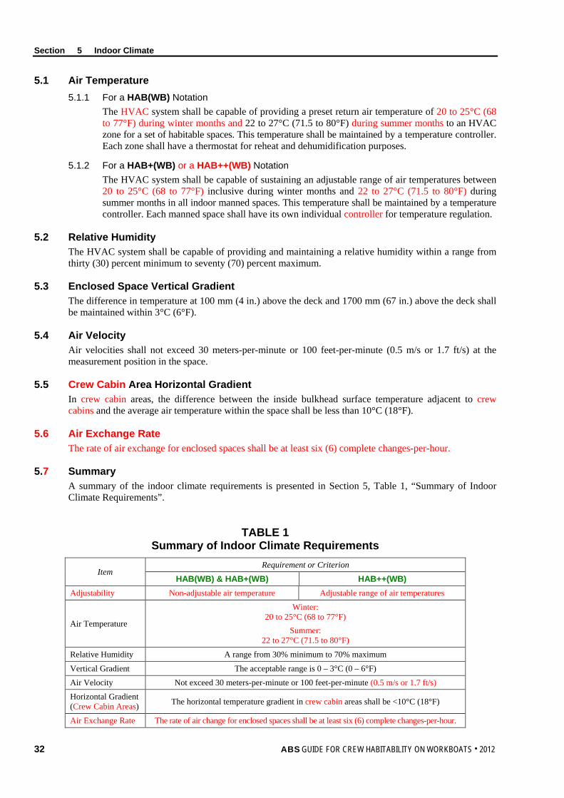
Section 5 Indoor Climate
32 ABS GUIDE FOR CREW HABITABILITY ON WORKBOATS . 2012
5.1 Air Temperature 5.1.1 For a HAB(WB) Notation
The HVAC system shall be capable of providing a preset return air temperature of 20 to 25°C (68 to 77°F) during winter months and 22 to 27°C (71.5 to 80°F) during summer months to an HVAC zone for a set of habitable spaces. This temperature shall be maintained by a temperature controller. Each zone shall have a thermostat for reheat and dehumidification purposes.
5.1.2 For a HAB+(WB) or a HAB++(WB) Notation The HVAC system shall be capable of sustaining an adjustable range of air temperatures between 20 to 25°C (68 to 77°F) inclusive during winter months and 22 to 27°C (71.5 to 80°F) during summer months in all indoor manned spaces. This temperature shall be maintained by a temperature controller. Each manned space shall have its own individual controller for temperature regulation.
5.2 Relative Humidity The HVAC system shall be capable of providing and maintaining a relative humidity within a range from thirty (30) percent minimum to seventy (70) percent maximum.
5.3 Enclosed Space Vertical Gradient The difference in temperature at 100 mm (4 in.) above the deck and 1700 mm (67 in.) above the deck shall be maintained within 3°C (6°F).
5.4 Air Velocity Air velocities shall not exceed 30 meters-per-minute or 100 feet-per-minute (0.5 m/s or 1.7 ft/s) at the measurement position in the space.
5.5 Crew Cabin Area Horizontal Gradient In crew cabin areas, the difference between the inside bulkhead surface temperature adjacent to crew cabins and the average air temperature within the space shall be less than 10°C (18°F).
5.6 Air Exchange Rate The rate of air exchange for enclosed spaces shall be at least six (6) complete changes-per-hour.
5.7 Summary A summary of the indoor climate requirements is presented in Section 5, Table 1, “Summary of Indoor Climate Requirements”.
TABLE 1 Summary of Indoor Climate Requirements
Item Requirement or Criterion
HAB(WB) & HAB+(WB) HAB++(WB) Adjustability Non-adjustable air temperature Adjustable range of air temperatures
Air Temperature
Winter: 20 to 25°C (68 to 77°F)
Summer: 22 to 27°C (71.5 to 80°F)
Relative Humidity A range from 30% minimum to 70% maximum
Vertical Gradient The acceptable range is 0 – 3°C (0 – 6°F)
Air Velocity Not exceed 30 meters-per-minute or 100 feet-per-minute (0.5 m/s or 1.7 ft/s) Horizontal Gradient (Crew Cabin Areas) The horizontal temperature gradient in crew cabin areas shall be <10°C (18°F)
Air Exchange Rate The rate of air change for enclosed spaces shall be at least six (6) complete changes-per-hour.
Section 5 Indoor Climate
ABS GUIDE FOR CREW HABITABILITY ON WORKBOATS . 2012 33
6 Test Plan As stated in 1/7.3.1, “Test Plans”, a Test Plan shall be developed to serve as the principal means for submitting design details of the HVAC system for review by ABS Engineering and for verifying the measurements to be performed to verify compliance with indoor climate criteria.
6.1 Documentation The Test Plan shall identify spaces where measurements shall be taken and include the following documentation and data to enable ABS Engineering to verify compliance to the indoor climate criteria set in this Guide:
i) Appropriate vessel and HVAC system design specifications
ii) Schematics/layout drawings of the HVAC system
iii) General arrangement drawings of the vessel
A report of the total system Testing, Adjusting, and Balancing (TAB) shall be provided to ABS Engineering. The total system TAB shall be conducted in accordance with the National Environmental Balancing Bureau (NEBB) standard “NEBB Procedural Standards for Testing, Adjusting, Balancing of Environmental Systems” or other similar certification standards.
6.2 Test Personnel The Test Plan shall provide information about the Testing Specialist who will be conducting the test and their approval and certification in accordance with Appendix 2, “Procedural Requirements for ABS Recognized Ambient Environmental Testing Specialists”.
6.3 Test Conditions The Test Plan shall detail the conditions under which the tests will be performed. Details about test conditions are given in 5/7.3, “Test Conditions”.
6.4 Measurement Locations The Test Plan shall document, in detail, on appropriate drawings, all spaces or areas where measurements will be taken. Details on selecting measurement locations and determining transducer positions are provided in 5/7.4, “Measurement Locations”.
6.5 Data Acquisition and Instruments The Test Plan shall provide information regarding the methods and instrumentation to be used for measurement and data collection. Instrumentation specification details shall include type of instruments to be used, accuracy, response time, calibration and sensitivity. More details on data acquisition and instruments are provided in 5/7.2, “Data Acquisition and Instruments”.
6.6 Data Analysis The Test Plan shall provide information regarding the methods, software, and instrumentation to be used for data analysis.
6.7 Test Schedule The Test Plan shall provide information regarding the proposed test schedule.
Section 5 Indoor Climate
34 ABS GUIDE FOR CREW HABITABILITY ON WORKBOATS . 2012
7 Test Requirements
7.1 General Indoor climate measurements shall be in accordance with the requirements of ANSI/ASHRAE 55a and ANSI/ASHRAE 15. When the procedures described in this Guide deviate from those in ANSI/ASHRAE 55a and ANSI/ASHRAE 15, the more stringent requirement shall take precedence.
7.2 Data Acquisition and Instruments The thermal measurement instrumentation shall meet or exceed the minimum characteristics of instruments for measuring physical quantities characterizing an environment specified in ISO 7726.
The following quantities shall be measured in each of the spaces or zones identified in the Test Plan and the results noted in the Indoor Climate Test Report:
i) Air temperature
ii) Relative humidity
iii) Air velocity
iv) Vertical gradient
v) Horizontal gradient (in crew cabin spaces only)
The air temperature and humidity measurements shall be made at least every five (5) minutes for a minimum period of one (1) hour. The minimum, maximum, and average values for the 1-hour period shall be reported for each space measured. For the HAB+(WB) and HAB++(WB) notations, the temperature control for a specific space shall be set to the lower requirement level of 20°C (68°F) for the first half-hour and to 27°C (80°F) for the second half-hour of measurement. Note: Data loggers are a type of device that can be left unattended to capture data. These type devices have been proven
effective in gathering temperature and humidity values.
The measuring period for determining the average air velocity at any location shall be three (3) minutes.
Surface temperatures for all wall surfaces that are adjacent to crew cabins shall be measured for determining the horizontal gradient in crew cabin spaces.
7.3 Test Conditions In order to determine the effectiveness of the HVAC system at providing the environmental conditions specified in this Guide, measurements shall be made under the following conditions:
7.3.1 Testing Testing of identified spaces can be performed in port and at sea, provided the provisions of the required test conditions stated here are in compliance at the time the measurements are made and recorded. In the case where some testing is performed in port, confirmatory testing shall be performed while in dynamic positioning operations with all normally functioning operations. This testing will consist of a sample of manned spaces on the weather boundary and will be selected by the ABS Surveyor.
7.3.2 Equipment Operation The HVAC system shall be operating in the normal operation or mode.
7.3.3 Doors and Windows The space doors and windows shall be closed during the evaluation period, except for routine entry and exit. Any open doors or windows should be noted in the Indoor Climate Test Report.
7.3.4 Equipment and Furnishings Spaces shall be furnished with all usual equipment and furnishings normally found in the space. Equipment shall be configured to operate in its normal operating mode.
Section 5 Indoor Climate
ABS GUIDE FOR CREW HABITABILITY ON WORKBOATS . 2012 35
7.3.5 Weather and Climatic Conditions When thermal conditions in the manned space have a high sensitivity to time of day and weather conditions (e.g., spaces adjacent to exterior bulkheads), the measurement should be made such that the high and low extremes of the thermal parameters are determined (e.g., measurements could therefore be taken during the day and night in the same space). If possible, measurements should be taken with little or no cloud cover.
7.3.6 Test Interference During the indoor climate measurements, any activity that might affect the indoor climatic variables in the space shall be avoided. For this reason, only the personnel needed for the normal operation of the equipment in the space and those carrying out the measurements shall be present in the space being tested.
Doors and windows shall be closed, except where they are normally left open (such as the door on the lee side of the navigation bridge, which may normally be open). Any open doors or windows shall be noted in the Indoor Climate Test Report.
7.4 Measurement Locations 7.4.1 Selection of Spaces where Measurements are to be Conducted
The aim when selecting indoor climate measurement locations shall be to obtain a representative sample of data that reflects the actual conditions in manned spaces. For practical reasons, it is important to select the locations such that an appropriate amount of sample data can be collected during the testing phase. The measurement locations shall be selected in accordance with the following criteria:
i) Select potential problem areas where the influence of internal conditions or factors may adversely impact the quality of the indoor climate in manned spaces, accommodation areas and recreation areas. Internal conditions include space proximity to equipment that radiates or absorbs heat (e.g., engine exhaust trunks, freezer spaces, galley, scullery, etc.) and surfaces with thermal differentials in excess of 10°C (18°F) from the ambient temperature in the space. Living and working areas at the ends of HVAC ductwork or piping runs (for heating or cooling) shall be selected as potential problem locations. Measurements shall be taken in all identified potential problem areas.
ii) Select potential problem areas where the influence of external ambient environmental conditions (e.g., sun, wind, precipitation, etc.) may adversely impact the quality of the indoor climate. These areas include manned spaces, accommodation areas and recreation areas which may be outboard or adjacent to the vessel’s hull. Measurements shall be taken in all identified problem areas.
iii) Where a single instance of one (1) type of space exists within the vessel (e.g., bridge, mess room, gymnasium, library, etc.), the location shall be selected for measurement.
iv) Where multiple instances of one (1) type of space exist (e.g., cabins/staterooms, or recreation areas), a representative sample of at least twenty-five (25) percent of each type (e.g., one-man room, two-man room, etc.) shall be selected for measurement. The worst case locations are to be considered part of the representative sample, if applicable.
All of these measurement locations must be selected at locations port, starboard, fore, amidships and aft. The worst case locations can be considered part of the representative sample for crew cabins and staterooms, if applicable.
7.4.2 Walkthrough Verification Inspection Locations All normally manned spaces shall be subject to a walkthrough inspection by the ABS Surveyor. The number and locations of the walkthrough inspections will be determined by the ABS Surveyor. The purpose of the walkthrough verification is to subjectively assess the indoor climate qualities. At the discretion of the ABS Surveyor, additional measurements may be required.
Section 5 Indoor Climate
36 ABS GUIDE FOR CREW HABITABILITY ON WORKBOATS . 2012
7.4.3 Transducer Measurement Positions For each space identified in the Test Plan, the transducer locations shall be standardized as follows:
i) Air temperature and relative humidity measuring instrumentation shall be set up approximately in the middle of the space to measure general space temperature and humidity levels. Air temperature shall be simultaneously measured at approximately 100 mm (4 in.), 1100 mm (43 in.) and 1700 mm (67 in.) above the deck. Relative humidity shall be measured at a height of approximately 1700 mm (67 in.) above the deck.
ii) Air velocity shall be measured at approximately 100 mm (4 in.), 1100 mm (43 in.) and 1700 mm (67 in.) above the deck in manned spaces, as applicable (to assure air velocity is not excessive). This measurement should be taken in the center of the space. Air velocity only needs to be measured once per testing location.
iii) For crew cabin spaces, inside wall surface temperatures shall be captured at approximately 300 mm (12 in.) above the mattress.
8 Test Report As stated in 1/7.3.2, “Test Reports”, a Test Report shall be submitted to the ABS Surveyor to determine whether the indoor climate levels meet the criteria and whether this part of the notation requirement has been met. The details listed in the following Paragraphs shall be provided in the Indoor Climate Test Report.
8.1 Test Details The following details shall be provided for each period of testing:
i) Vessel latitude and longitude coordinates during testing
ii) Weather conditions and meteorological data (i.e., wind speed and direction, ambient outdoor air temperature, outdoor humidity, barometric pressure) at the onset of every data collection period and at intervals of every four (4) hours (if needed) during any data collection period. Weather conditions shall also be reported at the end of each data collection period.
iii) Any indications of abnormal activities or conditions during the test that might skew results
8.2 Transducer Measurement Positions Actual measurement locations and transducer positions shall be indicated on appropriate drawings.
8.3 Measurement Equipment Details Details of measuring and analysis equipment (e.g., manufacturer, type and serial number, accuracy, sampling frequency and resolution) shall be provided.
Copies of the relevant instrumentation reference calibration certificates, together with the results of field setup and calibration checks before and after the field tests, shall be provided.
8.4 Results The following results, per measurement location and sample period as appropriate for notation, shall be provided in table format:
i) Measurement position
ii) Number of people present in the space at time of measurement
iii) Measurement period
iv) Time at start and end of measurement
v) Air temperature (minimum, maximum, and average) at 100 mm (4 in.) above deck
vi) Air temperature (minimum, maximum, and average) at 1100 mm (43 in.) above deck
vii) Air temperature (minimum, maximum, and average) at 1700 mm (67 in.) above deck
Section 5 Indoor Climate
ABS GUIDE FOR CREW HABITABILITY ON WORKBOATS . 2012 37
viii) Relative humidity (minimum, maximum, and average) at 1700 mm (67 in.) above deck
ix) Air velocity at 100, 1100, and 1700 mm (4, 43, and 67 in.) above deck at measurement positions
x) Vertical gradient (Average air temperature at 1700 mm (67 in.) minus average air temperature at 100 mm (4 in.) above deck)
xi) Horizontal gradient (Side wall surface temperature in crew cabin spaces minus average air temperature at 1100 mm (43 in.) above deck crew cabin areas)
xii) Wind speed and direction, ambient outdoor air temperature, outdoor humidity, and barometric pressure corresponding to indoor measurement periods
For all the remaining spaces that were checked through walkthrough verification inspection and spot check measurements, the following information shall be provided:
i) Name and number of space
ii) Walkthrough inspection observations
iii) Measurement results if necessary
8.5 Deviations All deviations from the approved Test Plan shall be reported.
8.6 Surveyor Witnessing Documentation The equipment calibration and data collection process of the indoor climate tests shall be witnessed by an ABS Surveyor. The ABS Surveyor shall provide documentation stating whether all steps of the indoor climate testing were completed to their satisfaction. A copy of the witnessing document shall be given to the person conducting the testing for insertion into the final Indoor Climate Test Report. The original shall be retained for ABS’ files.
9 Results The Indoor Climate Test Report and test results shall be reviewed by the ABS Surveyor against the appropriate HAB(WB), HAB+(WB), and HAB++(WB) criteria for notation confirmation.
38 ABS GUIDE FOR CREW HABITABILITY ON WORKBOATS . 2012
S e c t i o n 6 : L i g h t i n g
S E C T I O N 6 Lighting
1 Background The lighting of seafarer spaces should facilitate visual task performance and facilitate movement in the space and aid in the creation of an appropriate visual environment. Lighting design involves integrating these aspects to provide adequate illumination for the safety and well-being of the crew as well as for the various tasks performed onboard vessels.
The selection of appropriate illuminance levels for specific tasks and seafarer spaces is an important consideration in the design of lighting systems. There is a difference of opinion as to what levels of light may be considered best for visual tasks. Since illuminance recommendations are generally consensus values, for any task, a range of illuminances may apply.
Since visual tasks performed within habitable spaces onboard a vessel are generally similar to tasks encountered ashore, requirements for illuminance on vessels generally correspond to those tasks performed in living, working, and recreation areas on shore.
Visual tasks encountered on vessels vary and lighting provided can influence ability to see and perform those tasks. Some vision and lighting considerations include task duration, visual fatigue, task criticality, veiling reflections, shadows, and abilities of the observer. The presence of glare is a concern and is often difficult to identify, measure, and assess. Glare is often transient (based on factors such as the direction of the sun to illuminated components or from the placement of lighting fixtures) and therefore difficult to anticipate. As part of lighting data collection, glare shall be subjectively evaluated jointly by the Testing Specialist and the attending Surveyor witnessing the collection of lighting data. These assessments shall be made as part of the activities discussed in 6/7.4.2, “Walkthrough Verification Inspection Locations”.
Measurement of ambient lighting need only be performed once, under condition of transit, during dynamic positioning, or at pier side when all external light sources can be blocked out.
2 Scope This Section provides criteria for assessing the illuminance levels of general lighting and task lighting on vessels. The main objective of the assessment is to determine whether the various lighting systems comply with minimum standards to accommodate crew visual task performance and facilitate crew movements and well-being and safety onboard vessels.
Lighting criteria are based on currently available objective standards and research data. Compliance with this Section is a prerequisite for the workboat Habitability (HAB(WB)), workboat Habitability Plus (HAB+(WB)), or workboat Habitability Plus Plus (HAB++(WB)) notation confirmation.
3 Terminology Disability Glare: Glare which reduces the ability to perform a visual task.
Discomfort Glare: Glare which produces viewer discomfort, but which does not significantly interfere with visual task performance or visibility.
General Lighting: Lighting designed to provide a substantially uniform level of illuminance throughout an area, exclusive of any provision for special, localized tasks. Such lighting should be provided by fixed luminaires.
Glare: The discomfort or impairment of vision experienced when parts of the visual field are excessively bright in relation to the general surroundings.
Section 6 Lighting
ABS GUIDE FOR CREW HABITABILITY ON WORKBOATS . 2012 39
Illuminance: The luminous flux density at a surface (or the amount of light falling on an object or surface), i.e., the luminous flux incident-per-unit area. Illuminance is measured in units of Lux (lm/m2) or foot-candles (fc; lm/ft2). One foot-candle equals 10.76 Lux.
Lumen: The International System of Units (SI) of luminous flux, used in describing a quantity of light emitted by a source or received by a surface.
Luminaire: A complete lighting unit consisting of a lamp(s) together with the parts designed to distribute the light, to position and protect the lamp, and to connect the lamp to the power supply.
Luminance: The photometric brightness of an illuminated surface (or the amount of light emitted or reflected from the surface). The SI unit of luminance is candela-per-square meter (cd/m2).
Luminous Flux: The light emitted by a source, or received by a surface and indicates the intensity of a source. Flux is expressed in lumens.
Lux: a unit of illumination, equivalent to 0.0929 foot-candle and equal to the illumination produced by luminous flux of one lumen falling perpendicularly on a surface one meter square. Also called meter-candle Red or Low-level White Illuminance: Lighting provided to accommodate efficient dark adaptation in areas where seeing tasks are performed during nighttime operations and in areas where people need to move from a lit interior into a dark environment and maintain good vision.
Reference Calibration: Calibration of a measuring instrument, conducted by an accredited Testing and Calibration Laboratory, with traceability to a national or international standard.
Task Lighting: Lighting provided to meet the illuminance requirements of a specific task. Task lighting refers to the total illuminance requirement that may be obtained by supplementary lighting provided in addition to the general illuminance. Such lighting may be provided by fixed luminaires, or via floor lamps or table lamps.
Task Plane: The horizontal, vertical, or inclined plane in which the visual task lies. If no information is available, the task plane may be considered to be the horizontal and at 750 mm (29.5 in.) above the deck for seated tasks and 1000 mm (39.5 in.) for standing tasks.
4 Associated Documentation The following documents provide details about Test Plan preparation, test measurement procedures and/or test reporting:
• IESNA RP-12-97, Recommended Practice for Marine Lighting
• ISO 8995:2000 (CIES 008/E), Lighting of indoor work places
5 Criteria (1 September 2013) The lighting criteria for the workboat Habitability notations are provided in:
• Section 6, Table 1, “Lighting Criteria for Crew Accommodation Spaces”
• Section 6, Table 2, “Lighting Criteria for Navigation and Control Spaces”
• Section 6, Table 3, “Lighting Criteria for Service Spaces”
• Section 6, Table 4, “Lighting Criteria for Operating and Maintenance Spaces/Areas”
• Section 6, Table 5, “Lighting Criteria for Red or Low-level White Illuminance”
For lighting, the criteria for HAB(WB), HAB+(WB), and HAB++(WB) are the same. In this Section, general lighting and task lighting requirements are provided for crew tasks and spaces normally encountered on vessels. The lighting levels provided in the tables are for new lamps. Emergency lighting is covered in SOLAS and IMO Resolutions and was not considered in the selection of the lighting levels provided in this Guide.
The criteria in this Section are applicable to the entire vessel, not just manned spaces.
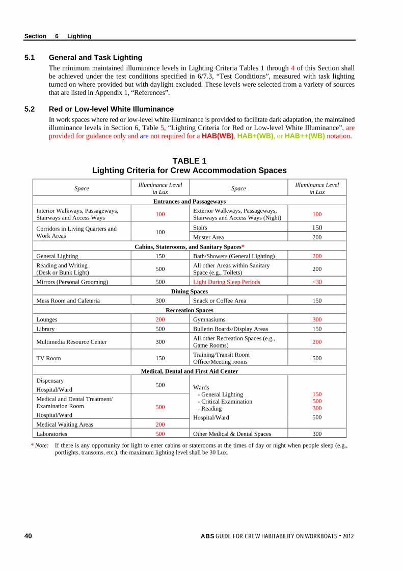
Section 6 Lighting
40 ABS GUIDE FOR CREW HABITABILITY ON WORKBOATS . 2012
5.1 General and Task Lighting The minimum maintained illuminance levels in Lighting Criteria Tables 1 through 4 of this Section shall be achieved under the test conditions specified in 6/7.3, “Test Conditions”, measured with task lighting turned on where provided but with daylight excluded. These levels were selected from a variety of sources that are listed in Appendix 1, “References”.
5.2 Red or Low-level White Illuminance In work spaces where red or low-level white illuminance is provided to facilitate dark adaptation, the maintained illuminance levels in Section 6, Table 5, “Lighting Criteria for Red or Low-level White Illuminance”, are provided for guidance only and are not required for a HAB(WB), HAB+(WB), or HAB++(WB) notation.
TABLE 1 Lighting Criteria for Crew Accommodation Spaces
Space Illuminance Level in Lux Space Illuminance Level
in Lux Entrances and Passageways
Interior Walkways, Passageways, Stairways and Access Ways 100 Exterior Walkways, Passageways,
Stairways and Access Ways (Night) 100
Corridors in Living Quarters and Work Areas 100
Stairs 150 Muster Area 200
Cabins, Staterooms, and Sanitary Spaces* General Lighting 150 Bath/Showers (General Lighting) 200 Reading and Writing (Desk or Bunk Light) 500 All other Areas within Sanitary
Space (e.g., Toilets) 200
Mirrors (Personal Grooming) 500 Light During Sleep Periods <30 Dining Spaces
Mess Room and Cafeteria 300 Snack or Coffee Area 150 Recreation Spaces
Lounges 200 Gymnasiums 300 Library 500 Bulletin Boards/Display Areas 150
Multimedia Resource Center 300 All other Recreation Spaces (e.g., Game Rooms) 200
TV Room 150 Training/Transit Room Office/Meeting rooms 500
Medical, Dental and First Aid Center Dispensary Hospital/Ward
500 Wards - General Lighting - Critical Examination - Reading Hospital/Ward
150 500 300 500
Medical and Dental Treatment/ Examination Room Hospital/Ward
500
Medical Waiting Areas 200 Laboratories 500 Other Medical & Dental Spaces 300
* Note: If there is any opportunity for light to enter cabins or staterooms at the times of day or night when people sleep (e.g., portlights, transoms, etc.), the maximum lighting level shall be 30 Lux.
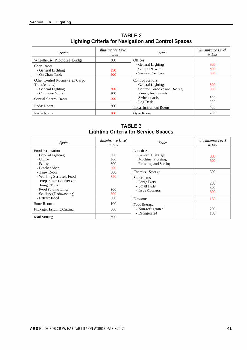
Section 6 Lighting
ABS GUIDE FOR CREW HABITABILITY ON WORKBOATS . 2012 41
TABLE 2 Lighting Criteria for Navigation and Control Spaces
Space Illuminance Level in Lux Space Illuminance Level
in Lux Wheelhouse, Pilothouse, Bridge 300 Offices
- General Lighting - Computer Work - Service Counters
300 300 300
Chart Room - General Lighting - On Chart Table
150 500
Other Control Rooms (e.g., Cargo Transfer, etc.) - General Lighting - Computer Work Central Control Room
300 300 500
Control Stations - General Lighting - Control Consoles and Boards, Panels, Instruments - Switchboards - Log Desk Local Instrument Room
300 300
500 500 400 Radar Room 200
Radio Room 300 Gyro Room 200
TABLE 3 Lighting Criteria for Service Spaces
Space Illuminance Level in Lux Space Illuminance Level
in Lux Food Preparation - General Lighting - Galley - Pantry - Butcher Shop - Thaw Room - Working Surfaces, Food Preparation Counter and Range Tops - Food Serving Lines - Scullery (Dishwashing) - Extract Hood Store Rooms Package Handling/Cutting
500 500 300 500 300 750
300 300 500 100 300
Laundries - General Lighting - Machine, Pressing, Finishing and Sorting
300 300
Chemical Storage 300 Storerooms - Large Parts - Small Parts - Issue Counters
200 300 300
Elevators 150 Food Storage - Non-refrigerated - Refrigerated
200 100
Mail Sorting 500
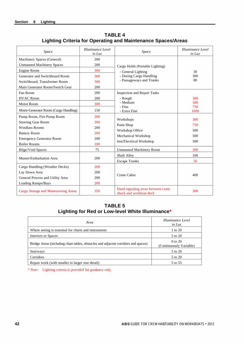
Section 6 Lighting
42 ABS GUIDE FOR CREW HABITABILITY ON WORKBOATS . 2012
TABLE 4 Lighting Criteria for Operating and Maintenance Spaces/Areas
Space Illuminance Level in Lux Space Illuminance Level
in Lux Machinery Spaces (General) Unmanned Machinery Spaces
200 200 Cargo Holds (Portable Lighting)
- General Lighting - During Cargo Handling - Passageways and Trunks
30
300 80
Engine Room 300 Generator and Switchboard Room Switchboard, Transformer Room Main Generator Room/Switch Gear
300 500 200
Fan Room HVAC Room
200 200
Inspection and Repair Tasks - Rough - Medium - Fine - Extra Fine
300 500 750 1000
Motor Room 300
Motor-Generator Room (Cargo Handling) 150
Pump Room, Fire Pump Room Steering Gear Room Windlass Rooms Battery Room Emergency Generator Room Boiler Rooms
200 200 200 200 200 100
Workshops Paint Shop Workshop Office Mechanical Workshop Inst/Electrical Workshop
300 750 500 500 500
Bilge/Void Spaces 75 Unmanned Machinery Room 200
Muster/Embarkation Area 200 Shaft Alley 100 Escape Trunks 50
Cargo Handling (Weather Decks) Lay Down Area General Process and Utility Area Loading Ramps/Bays
200 200 200 200
Crane Cabin 400
Cargo Storage and Maneuvering Areas 350 Hand signaling areas between crane shack and workboat deck 300
TABLE 5 Lighting for Red or Low-level White Illuminance*
Area Illuminance Level in Lux
Where seeing is essential for charts and instruments 1 to 20 Interiors or Spaces 5 to 20
Bridge Areas (including chart tables, obstacles and adjacent corridors and spaces) 0 to 20 (Continuously Variable)
Stairways 5 to 20 Corridors 5 to 20 Repair work (with smaller to larger size detail) 5 to 55
* Note: Lighting criteria is provided for guidance only.
Section 6 Lighting
ABS GUIDE FOR CREW HABITABILITY ON WORKBOATS . 2012 43
6 Test Plan As stated in 1/7.3.1, “Test Plans”, a Test Plan shall be developed to serve as the principal means for submitting design details of the lighting system for review by ABS Engineering and for verifying the measurements to be performed to verify compliance with lighting criteria. The Test Plan shall include the following:
6.1 Documentation The Test Plan shall include appropriate design information and layout drawings showing the hull outline, bulkheads, access routes, location of luminaires, outlines of major furniture and equipment, and the space name and number. The drawings shall be to a scale and sized to permit the scaling of survey points (required by 6/7.4, “Measurement Locations”) and lighting equipment and the recording of luminance and other relevant data.
6.2 Test Personnel The Test Plan shall provide information about the Testing Specialist who will be conducting the test and their approval and certification in accordance with Appendix 2, “Procedural Requirements for ABS Recognized Ambient Environmental Testing Specialists”.
6.3 Test Conditions The Test Plan shall detail the conditions under which the tests will be performed. Details about test conditions are given in 6/7.3, “Test Conditions”.
6.4 Measurement Locations The Test Plan shall document, in detail, on appropriate drawings, all spaces or areas where measurements will be taken. In addition, measurement positions within these areas shall be indicated. Details on selecting measurement locations are provided in 6/7.4, “Measurement Locations”.
6.5 Data Acquisition and Instruments The Test Plan shall provide information regarding the methods and instrumentation to be used for measurement and data collection. Instrumentation specification details shall include type of instruments to be used, accuracy, calibration, and sensitivity. More details on data acquisition and instruments are provided in 6/7.2, “Data Acquisition and Instruments”.
6.6 Data Analysis The Test Plan shall provide information regarding the methods used for data analysis.
6.7 Test Schedule The Test Plan shall provide information regarding the proposed test schedule.
7 Test Requirements
7.1 General Illuminance measurements shall be carried out as described below.
7.2 Data Acquisition and Instruments The illuminance meter (light meter) should meet the requirements specified in Section B.5 of IESNA RP-12-97. This defines the instrumentation requirements for measuring white light.
Instruments used to measure red illuminance should meet the requirements specified in Section B.8.4 of IESNA RP-12-97. Note: The measurement of red and/or low level white illuminance is not required for workboat Habitability notation
Section 6 Lighting
44 ABS GUIDE FOR CREW HABITABILITY ON WORKBOATS . 2012
7.3 Test Conditions The test conditions required for Lighting measurements shall be in accordance with the following Subparagraphs:
7.3.1 Location Lighting measurements may be taken in port, at sea, or both, since the measurements are not dependent on vessel operation.
7.3.2 Spaces with Windows/Portlights In spaces with windows or portlights where the minimum lighting level should be provided by artificial light sources only, lighting measurements shall be taken after dark, or during the day provided all natural lighting is blocked out.
7.3.3 Spaces without Windows/Portlights Interior spaces with no windows or portlights can be measured during daylight hours.
7.3.4 Stray Light Stray light (e.g., deck lighting and moonlight) shall be capable of being masked out as far as practicable. Where it is not possible, measurements of stray light, at appropriate positions, with all lighting turned off, shall be obtained. These readings shall then be deducted from readings taken at the same positions, with the lighting turned on, to determine the illuminance from the lighting.
7.3.5 Light for Sleep Lighting measurements shall be taken in cabins and staterooms with all cabin and stateroom lights turned off and curtains, shutters, etc., closed.
7.3.6 Test Interference During the lighting measurements, shadows on the light meter caused by any kind of human activity shall be avoided. For this reason, only the personnel needed for the normal operation of the equipment in the space and those carrying out the measurements shall be present in the space being tested.
Doors and windows shall be closed, except where they are normally left open (such as the door on the lee side of the navigation bridge, which may normally be open). Any open doors or windows shall be noted in the Lighting Test Report. Spaces shall be furnished with all usual equipment and furnishings normally found in the space.
7.3.7 External (Deck) Lighting External areas (cargo handling, cargo lay down areas, and external operating consoles) shall be tested on dark evenings without contribution of light to the deck and cargo handling areas from shore lights. Light measurements taken for these locations shall result from lighting systems aboard (excepting star and moon light contributions).
7.4 Measurement Locations 7.4.1 Selection of Spaces where Measurements are to be Conducted
The aim when selecting lighting measurement locations shall be to obtain a representative sample of data that represents the actual conditions in the manned crew spaces listed in the Lighting Criteria Tables 1 to 4 of this Section. For practical reasons, it is important to select the locations such that an appropriate amount of sample data can be collected during the testing phase. The measurement locations shall be selected in accordance with the following criteria:
i) Select problem areas based on the potential for excessive external illumination (daylight) into the space (e.g., bridge). Measurements shall be taken in all identified problem areas.
ii) Select potential problem areas based on the positioning of luminaires in the space as indicated on the drawings (e.g., uneven spacing of luminaires resulting in non-uniform illuminance levels and dimly lit areas). Measurements shall be taken in all problem areas.
iii) Where a single instance of one (1) type of space exists within the vessel (e.g., bridge, mess room, gymnasium, library, etc.), the location shall be selected for measurement.
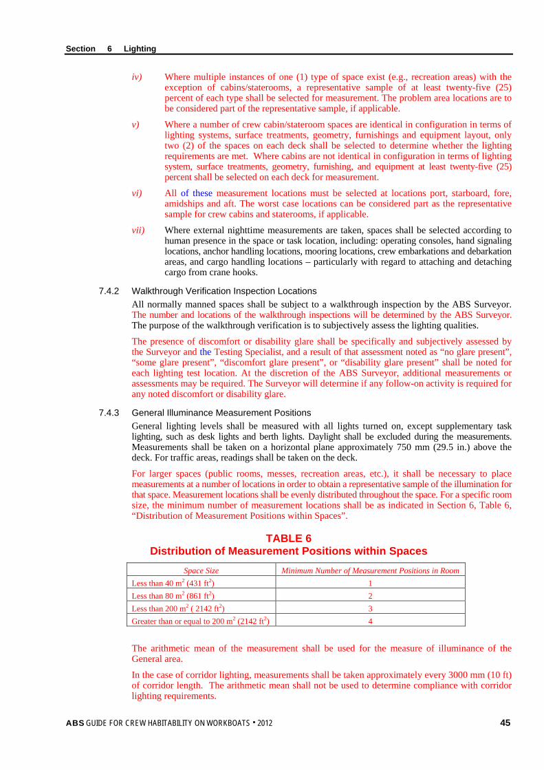
Section 6 Lighting
ABS GUIDE FOR CREW HABITABILITY ON WORKBOATS . 2012 45
iv) Where multiple instances of one (1) type of space exist (e.g., recreation areas) with the exception of cabins/staterooms, a representative sample of at least twenty-five (25) percent of each type shall be selected for measurement. The problem area locations are to be considered part of the representative sample, if applicable.
v) Where a number of crew cabin/stateroom spaces are identical in configuration in terms of lighting systems, surface treatments, geometry, furnishings and equipment layout, only two (2) of the spaces on each deck shall be selected to determine whether the lighting requirements are met. Where cabins are not identical in configuration in terms of lighting system, surface treatments, geometry, furnishing, and equipment at least twenty-five (25) percent shall be selected on each deck for measurement.
vi) All of these measurement locations must be selected at locations port, starboard, fore, amidships and aft. The worst case locations can be considered part as the representative sample for crew cabins and staterooms, if applicable.
vii) Where external nighttime measurements are taken, spaces shall be selected according to human presence in the space or task location, including: operating consoles, hand signaling locations, anchor handling locations, mooring locations, crew embarkations and debarkation areas, and cargo handling locations – particularly with regard to attaching and detaching cargo from crane hooks.
7.4.2 Walkthrough Verification Inspection Locations All normally manned spaces shall be subject to a walkthrough inspection by the ABS Surveyor. The number and locations of the walkthrough inspections will be determined by the ABS Surveyor. The purpose of the walkthrough verification is to subjectively assess the lighting qualities.
The presence of discomfort or disability glare shall be specifically and subjectively assessed by the Surveyor and the Testing Specialist, and a result of that assessment noted as “no glare present”, “some glare present”, “discomfort glare present”, or “disability glare present” shall be noted for each lighting test location. At the discretion of the ABS Surveyor, additional measurements or assessments may be required. The Surveyor will determine if any follow-on activity is required for any noted discomfort or disability glare.
7.4.3 General Illuminance Measurement Positions General lighting levels shall be measured with all lights turned on, except supplementary task lighting, such as desk lights and berth lights. Daylight shall be excluded during the measurements. Measurements shall be taken on a horizontal plane approximately 750 mm (29.5 in.) above the deck. For traffic areas, readings shall be taken on the deck.
For larger spaces (public rooms, messes, recreation areas, etc.), it shall be necessary to place measurements at a number of locations in order to obtain a representative sample of the illumination for that space. Measurement locations shall be evenly distributed throughout the space. For a specific room size, the minimum number of measurement locations shall be as indicated in Section 6, Table 6, “Distribution of Measurement Positions within Spaces”.
TABLE 6 Distribution of Measurement Positions within Spaces
Space Size Minimum Number of Measurement Positions in Room Less than 40 m2 (431 ft2) 1 Less than 80 m2 (861 ft2) 2 Less than 200 m2 ( 2142 ft2) 3 Greater than or equal to 200 m2 (2142 ft2) 4
The arithmetic mean of the measurement shall be used for the measure of illuminance of the General area.
In the case of corridor lighting, measurements shall be taken approximately every 3000 mm (10 ft) of corridor length. The arithmetic mean shall not be used to determine compliance with corridor lighting requirements.
Section 6 Lighting
46 ABS GUIDE FOR CREW HABITABILITY ON WORKBOATS . 2012
7.4.4 Task Lighting Measurement Positions For task area lighting (such as consoles, control stations, workbenches, computer workstations, desktops and meeting tables, medical stations, galley areas, and maintenance workstations), a representative set of readings shall be taken over the task surface with the worker in the normal working position. Task lighting shall be measured with both general and supplementary task lighting turned on. Daylight shall be excluded during the measurements.
Measurements of task lighting shall be made on the surface or in the plane of the task (horizontal, vertical or at an angle). For small task surfaces, smaller than 0.5 m2 (5 ft2), a single measurement shall be taken at the center of the task surface. For larger task surfaces (0.5 m2 (5 ft2) or larger), the illuminance shall be measured by dividing the task surface into a grid no larger than 0.5 m2 (5 ft2) and averaging the measurements taken at the grid intersections.
Measurements for mirrors shall be taken approximately 400 mm (16 in.) away from the surface of the mirror. For berths and bunks, measurements shall be taken at a point approximately 300 mm (12 in.) above the top of the mattress and 600 mm (24 in.) from the head of the bed.
7.4.5 Red and Low-level White Illuminance Guidance for the measurement of red and low-level white is provided in B.8.4 in IESNA RP-12-97. These measurements are not required for the Habitability notation.
8 Test Report As stated in 1/7.3.2, “Test Reports”, a Test Report shall be submitted to the ABS Surveyor to determine whether the lighting levels meet the minimum requirements and whether this part of the notation requirement has been met. The details listed in the following paragraphs shall be provided in the Lighting Test Report.
8.1 Test Details The following details shall be provided for each period of testing:
i) Time of day
ii) External lighting conditions (e.g., Were measurements taken in port or at sea? Were measurements taken during daylight hours or after dark?)
8.2 Measurement Positions Actual measurement locations shall be indicated on appropriate drawings.
8.3 Measurement Equipment Details Details of measuring equipment (e.g., manufacturer, type and serial number, accuracy and resolution) shall be provided.
Copies of the relevant instrumentation reference calibration certificates, together with the results of field setup and calibration checks before and after the field tests, shall be provided.
8.4 Results The following results, per space, shall be provided in table format:
i) Name and number of space
ii) Task areas (if any) in space
iii) Average lighting level for general lighting
iv) Average lighting level for task lighting on each task surface or plane in space
v) Corridor lighting measurements
vi) Lighting level in cabins/staterooms with lights turned off and curtains, shutters, deadlights, etc., closed
vii) Presence of glare at specific workstations within the space and any follow-up activity requirements
Section 6 Lighting
ABS GUIDE FOR CREW HABITABILITY ON WORKBOATS . 2012 47
For all the remaining spaces that were checked through walkthrough verification inspection and spot check measurements, the following information shall be provided:
i) Name and number of space
ii) Walkthrough inspection observations
iii) Measurement results if necessary
8.5 Deviations All deviations from the approved Test Plan shall be reported.
8.6 Surveyor Witnessing Documentation An ABS Surveyor shall witness the equipment calibration and data collection process of the lighting tests. The ABS Surveyor shall provide documentation stating whether all steps of the lighting testing were completed to their satisfaction. A copy of the witnessing document shall be given to the person conducting the testing for insertion into the final Lighting Test Report. The original shall be retained for ABS’ files.
9 Results The Lighting Test Report and test results shall be reviewed by the ABS Surveyor against the lighting criteria for notation confirmation.
48 ABS GUIDE FOR CREW HABITABILITY ON WORKBOATS . 2012
A p p e n d i x 1 : R e f e r e n c e s
A P P E N D I X 1 References
1 General References 1 American Bureau of Shipping. Guide for Crew Habitability on Ships. Houston, TX.
2 American Bureau of Shipping. Rules for Materials and Welding: Aluminum and Fiber Reinforced Plastics. Houston, TX.
3 American Bureau of Shipping. Rules for Building and Classing Steel Vessels. Houston, TX.
4 American Bureau of Shipping. Rules for Building and Classing Steel Vessels for Service on Rivers and Intracoastal Waterways. Houston, TX.
5 American Bureau of Shipping. Rules for Building and Classing Steel Vessels Under 90 Meters (295 Feet) in Length. Houston, TX.
2 Accommodation Area References 1 American Society for Testing and Materials. (2006). Standard practice for human engineering design
for marine systems, equipment and facilities (ASTM F 1166). West Conshohocken, PA.
2 International Labor Office. (1949). Accommodation of Crews Convention (Revised) (Convention C92). Geneva.
3 International Labor Office. (1970). Accommodation of Crews (Supplementary Provisions Convention (Convention C133). Geneva.
4 International Labor Office. (1998). Maritime labor conventions and recommendations (4th ed.). Geneva.
5 International Labor Organization. Maritime Labour Convention, 2006. Geneva.
6 International Maritime Organization. (1997). International Convention of the Safety of Life at Sea: Means of escape (Chapter II-2, Regulation 28). London.
7 International Organization of Masters, Mates, & Pilots. Contract requirements for both existing and new ship construction. Linthicum Heights, MD.
8 National Fire Protection Association (NFPA). (1997). Life safety code 101. Quincy, MA.
9 Norwegian Oil Industry Association and The Federation of Norwegian Engineering Industries (NORSOK). (1996). Common requirements, architectural components & equipment (C-CR-002). Oslo.
10 Panero, J., and Zelnik, M. (1979). Human dimension & interior space: A source book of design reference standards. New York: Whitney Library of Design.
11 Sailor’s Union of the Pacific. (1996). Agreement between Sailor’s Union of the Pacific and American President Lines, Ltd. In the Offshore and Intercoastal Trades. San Francisco, CA.
12 Seafarers International Union. Contract requirements for unlicensed seamen. Camp Springs, MD.
13 Tillman, B. and Tillman, P. (2000). Personal Correspondence with ABS.
Appendix 1 References
ABS GUIDE FOR CREW HABITABILITY ON WORKBOATS . 2012 49
14 U.S. Coast Guard, Department of Transportation. (1998). Coast Guard Regulation 32, Subpart 32.40, Accommodations for officers and crew, (Code of Federal Regulations, 46CFR32.40, pp. 398-400). Washington, DC: U.S. Government Printing Office.
15 U.S. Coast Guard, Department of Transportation. (1998). Coast Guard Regulation 92, Subparts 92.10 to 92.25, 92.10-1 to 92.25-90 Construction and arrangement, (Code of Federal Regulations, 46CFR92.10-92.25, pp. 51-56). Washington, DC: U.S. Government Printing Office.
16 U.S. Coast Guard, Department of Transportation. (1998). Coast Guard Regulation 116, Subparts D to I, 116.400-116.970 Construction and arrangement, (Code of Federal Regulations, 46CFR116.400-116.970, pp. 339-357). Washington, DC: U.S. Government Printing Office.
17 U.S. Coast Guard, Department of Transportation. (1998). Coast Guard Regulation 116, Subpart K, 116.1110-116.1160 Construction and arrangement, (Code of Federal Regulations, 46CFR116.1110-116.1160, p.358). Washington, DC: U.S. Government Printing Office.
18 U.S. Coast Guard, Department of Transportation. (1998). Coast Guard Regulation 177, Subpart I, 177.900-177.970 Construction and arrangement, (Code of Federal Regulations, 46CFR177.900-177.970, pp. 214-216). Washington, DC: U.S. Government Printing Office.
19 U.S. Coast Guard, Office of Marine Safety. (1990). Load Line Technical Manual, Report Number USCG-M-1-90. Washington, DC
20 U.S. Department of Defense. (1998). Design criteria standard: Human engineering (MIL-STD-1472F). Washington, DC: U.S. Government Printing Office.
21 U.S. Department of Health and Human Service: Centers for Disease Control and Prevention. (1999). Recommended shipbuilding construction guidelines for cruise vessels destined to call on U.S. Ports. Atlanta, GA.
22 U.S. Department of Health, Education and Welfare: Food & Drug Administration. (1996). Handbook on sanitation of vessel construction: Standards of sanitation and ratproofing for the construction of vessels. Washington, DC.
23 U.S. Department of Labor (2000). Code of Federal Regulation, 29 CFR 1910. 23. Subpart D – Walking-Working Surfaces – Guarding floor and wall openings and holes. Washington, DC.
24 U.S. Department of Labor (2000). Code of Federal Regulation, 29 CFR 1910. 24. Subpart D – Walking-Working Surfaces – Fixed industrial stairs. Washington, DC.
25 U.S. Maritime Administration: National Maritime Resource and Education Center. (1995). Guideline specification for merchant ship construction, prepared by the Office of Ship Design. Washington, DC: U.S. Department of Transport.
26 U.S. Navy. (1994). Shipboard habitability design practices manual (T9640-AA-PRO-010/HAB). Arlington, VA: Naval Sea Systems Command.
27 U.S. Navy. (1995). General specifications for ships of the United States Navy (Section 612 – Liferails and Lifelines). Arlington, VA: Naval Sea Systems Command.
28 U.S. Navy. (1995). General specifications for ships of the United States Navy (Section 622 – Ladders, Handrails, Floor Plates, Staging, Gratings and Service Platforms). Arlington, VA: Naval Sea Systems Command.
29 U.S. Navy. (1995). General specifications for ships of the United States Navy (Section 640 – General Requirements for Habitability Spaces). Arlington, VA: Naval Sea Systems Command.
30 U.S. Navy. (1995). General specifications for ships of the United States Navy (Section 644 – Plumbing Fixtures and Fittings). Arlington, VA: Naval Sea Systems Command.
31 U.S. Navy. (1995). General specifications for ships of the United States Navy (Section 645 – Leisure and Community Facilities). Arlington, VA: Naval Sea Systems Command.
32 U.S. Navy. (1995). General specifications for ships of the United States Navy (Section 652 – Medical and Dental Spaces). Arlington, VA: Naval Sea Systems Command.
Appendix 1 References
50 ABS GUIDE FOR CREW HABITABILITY ON WORKBOATS . 2012
33 U.S. Navy. (1995). General specifications for ships of the United States Navy (Section 655 – Laundry & Dry Cleaning Facilities). Arlington, VA: Naval Sea Systems Command.
34 U.S. Navy. (1995). Shipboard habitability design criteria manual (T9640-AB-DDT- 010/HAB). Arlington, VA: Naval Sea Systems Command.
35 Woodson, W.E., Tillman, B., and Tillman, P. (1992). Human factors design handbook: Information and guidelines for the design of systems, facilities, equipment and products for human use (2nd ed.). New York: McGraw-Hill, Inc.
3 Whole-body Vibrations References 1 Griffin, M. J. (1990). Handbook of human vibration. London: Academic Press.
2 International Organization for Standardization. (2000). Mechanical Vibration and Shock – Guidelines for the Measurement, Reporting and Evaluation of Vibration with Regard to Habitability on Passenger and Merchant Ships. (ISO 6954:2000). Geneva.
3 International Organization for Standardization. (2003). Mechanical Vibration and Shock – Evaluation of Human Exposure to Whole Body Vibration – Part 2, Vibration in Buildings. (ISO 2631-2:2003). Geneva.
4 International Organization for Standardization. (1996). Acoustics – Measurement of noise shipboard vessels (ISO 2923: 1996). Geneva.
5 International Organization for Standardization. (2008) Mechanical Vibration on Ships – Part 2: Measurement of Structural Vibration (ISO 20283-2:2008). Geneva.
6 International Organization for Standardization. (1998). Mechanical mounting of accelerometers for measuring mechanical vibration and shock (ISO 5348: 1998(E)). Geneva.
7 International Organization for Standardization. (2005). Human response to vibration – Measuring instrumentation (ISO 8041: 2005). Geneva.
8 World Meteorological Organization (1995). International Codes Vol I.1 Part A Alphanumeric Codes. Boston, MA: American Meteorological Society.
4 Noise References 1 International Electrotechnical Commission. (2004). Electroacoustics – Sound Level Meters – Part 1:
Specifications (International Standard IEC 61672-1). Geneva: IEC Central Office.
2 International Electrotechnical Commission. (2000). Integrating-averaging sound level meters (International Standard IEC 60804(2000-10)). Geneva: IEC Central Office.
3 International Maritime Organization. (1981). Code on noise levels on-board ships (IMO Resolution A.468(XII)). London.
4 International Organization for Standardization. (1996). Acoustics – Measurement of noise on-board vessels (ISO 2923: 1996). Geneva.
5 Kryter, K.D. (1994). The handbook of hearing and the effects of noise: Physiology, psychology and public health. San Diego: Academic Press.
6 World Meteorological Organization (1995). International Codes Vol I.1 Part A Alphanumeric Codes. Boston, MA: American Meteorological Society.
Appendix 1 References
ABS GUIDE FOR CREW HABITABILITY ON WORKBOATS . 2012 51
5 Indoor Climate References 1 American National Standards Institute. (2010). Thermal environmental conditions for human
occupancy (ANSI/ASHRAE 55a-2010). Atlanta, GA: The American Society of Heating, Refrigerating and Air Conditioning Engineers, Inc.
2 American National Standards Institute. (2010). Practices for Measuring, Testing, Adjusting, and Balancing Shipboard HVAC&R Systems. (ANSI/ASHRAE 15-2010). Atlanta, GA: The American Society of Heating, Refrigerating and Air Conditioning Engineers, Inc.
3 International Organization for Standardization. (1998). Ergonomics of the thermal environment – Instruments for measuring physical quantities (ISO 7726: 1998 (E)). Geneva.
4 National Environmental Balancing Bureau. (2005). NEBB Procedural standards for testing, adjusting, balancing of environmental systems. Gaithersburg, MD.
6 Lighting References 1 Illuminating Engineering Society of North America. (1997). Recommended practice for marine
lighting (IESNA RP-12-97). New York.
2 International Organization for Standardization. (2000). Lighting of Indoor Work Places (ISO 8995:2000). Geneva.
52 ABS GUIDE FOR CREW HABITABILITY ON WORKBOATS . 2012
Appendix 2: Procedural Requirements for ABS Recognized Ambient Environmental Testing Specialists
A P P E N D I X 2 Procedural Requirements for ABS Recognized Ambient Environmental Testing Specialists
1 Terminology ABS Recognized Ambient Environmental Testing Specialists: Companies providing test or measurement services on behalf of the Owner of a vessel or shipyard for the purposes of meeting ABS workboat Habitability (HAB(WB), HAB+(WB), or HAB++(WB)) notation requirements. Approval of the Testing Specialist for workboats may also allow for testing and measurement services for other ABS Habitability, Comfort, and MLC notations:
• HAB, HAB+, HAB++
• HAB(OS), HAB+(OS), HAB++(OS)
• HAB(MODU), HAB+(MODU), HAB++(MODU)
• COMF, COMF+
• COMF(Y), COMFY+(Y)
• MLC-ACCOM, MLC-ACCOM(SPS), MLC-ACCOM(WB) Note that for COMF+ and COMF+(Y), motion sickness testing is required.
Calibration Checks: Field calibration of a measuring instrument, conducted before and after a field test, using a reference calibrated signal or through zero calibration.
Reference Calibration: Calibration of a measuring instrument, conducted by an accredited Testing and Calibration Laboratory, with traceability to a national or international standard.
2 Objective The objective of this procedure is to set basic standards for qualifying and certifying Testing Specialists performing ambient environmental testing and evaluation.
3 Application This procedure applies to the approval of Testing Specialists that provide the following ambient environment test services:
i) Whole-body Vibration measurements and analysis
ii) Noise measurements and analysis
iii) Indoor Climate measurement and analysis
iv) Lighting measurement and analysis
General requirements concerning Testing Specialists are given in A2/4.2, “General Requirements”. Specific requirements for the test services listed above are in Subsection A2/8, “Detailed Requirements by Ambient Environmental Aspect”.
Appendix 2 Procedural Requirements for ABS Recognized Ambient Environmental Testing Specialists
ABS GUIDE FOR CREW HABITABILITY ON WORKBOATS . 2012 53
4 Procedure for Approval and Certification
4.1 Documentation Requirements The following documents are to be submitted to ABS for review:
i) An outline of the company (e.g., organization and management structure) including subsidiaries or subcontractors to be included in the approval/certification
ii) A list of company experience in the specific ambient environmental aspect
iii) A list of test personnel documenting training and experience in conducting tests within the relevant ambient environmental aspect and qualifications according to recognized national, international, or industry standards, as applicable
iv) Description of equipment used for the measurement and analysis of the particular ambient environmental aspect for which approval is sought (e.g., calibration, accuracy, etc.)
The following documents will be reviewed during the initial approval audit (See A2/4.3, “Auditing of the Testing Specialist”):
i) A guide for operators of such equipment
ii) Training programs for test personnel
iii) Draft checklists and data recording sheets for recording results of the services referred to in Subsection A2/3, “Application”
iv) Quality Manual and/or documented procedures covering requirements in A2/4.5, “Quality Assurance System”
v) Evidence of approval/acceptance by certifying bodies, if any
vi) Information about other activities which may present a conflict of interest
vii) Record of customer claims and of corrective actions requested by certification bodies for the past year
viii) Where relevant, list and documentation of licenses granted by equipment’s manufacturer
ix) Example Test Plan(s) for the ambient environmental quality for which approval is requested
x) Example Test Reports.
4.2 General Requirements 4.2.1 Extent of Approval
The Testing Specialist shall demonstrate, as required by A2/4.2.2 “Training of Personnel” through A2/4.2.9, “Reporting”, that they have the competence, quality control, and quality assurance needed to perform the test and analysis services for which approval is sought.
4.2.2 Training of Personnel The Testing Specialist is responsible for the qualification and training of its personnel to a recognized national, international, or industry standard as applicable. Where such standards do not exist, the Testing Specialist is to define standards for the training and qualification of its personnel relevant to the functions each is authorized to perform. The personnel shall also have adequate experience and be familiar with the operation of any necessary equipment.
4.2.3 Supervision The Testing Specialist shall provide supervision for all services provided. The responsible supervisor shall have had a minimum of two (2) years experience in supervising tests in the ambient environmental aspect for which the Testing Specialist is recognized.
4.2.4 Personnel Records The Testing Specialist shall keep records of the recognized test personnel. The records shall contain information about formal education, training, and experience for the ambient environmental test services for which they are recognized.
Appendix 2 Procedural Requirements for ABS Recognized Ambient Environmental Testing Specialists
54 ABS GUIDE FOR CREW HABITABILITY ON WORKBOATS . 2012
4.2.5 Equipment and Facilities The Testing Specialist shall have the necessary equipment and facilities for the ambient environmental aspect to be tested. A record of the equipment used for ambient environmental testing shall be kept. The record shall contain information about maintenance and calibration.
4.2.6 Procedures The Testing Specialist shall have documented work procedures covering all ambient environmental test services supplied.
4.2.7 Subcontractors The Testing Specialist shall give information of agreements and arrangements if any parts of the services provided are subcontracted. Particular emphasis shall be given to quality management by the Testing Specialist in following-up of such subcontracts. Subcontractors providing anything other than subcontracted personnel or equipment shall also meet the requirements of A2/4.2, “General Requirements” and A2/4.5, “Quality Assurance System”.
4.2.8 Verification The Testing Specialist shall verify that the services provided are carried out in accordance with approved procedures.
4.2.9 Reporting The report shall be prepared in a form acceptable to ABS as outlined within this Guide. The report shall include a copy of the Certificate of Approval.
4.3 Auditing of the Testing Specialist Upon reviewing the submitted documents with satisfactory result, the Testing Specialist shall be audited for the initial certification process and then every three (3) years in order to ascertain that the Testing Specialist is duly organized and managed in accordance with the submitted documents and that it is considered capable of conducting the test services for which approval/certification is sought.
4.4 Certification Certification is conditional on a practical demonstration to ABS or its agent of the specific ambient environmental test service performance, as well as a sample of a satisfactory report.
4.5 Quality Assurance System The Testing Specialist shall have a documented system covering at least the following:
i) Operating instructions for the test equipment
ii) Maintenance and reference calibration of equipment
iii) Training programs for test personnel
iv) Supervision and verification to verify compliance with test procedures
v) Recording and reporting of information
vi) Quality management of subsidiaries and subcontractors
vii) Job preparation
viii) Periodic review of test process procedures, complaints, corrective actions, and issuance, maintenance, and control of documents.
A documented Quality Assurance system complying with the applicable ISO 9000 standard or equivalent and including the above items would be considered acceptable.
Appendix 2 Procedural Requirements for ABS Recognized Ambient Environmental Testing Specialists
ABS GUIDE FOR CREW HABITABILITY ON WORKBOATS . 2012 55
4.6 Testing Specialist Relations with the Test Equipment Manufacturer A company which works as a service station and conducts reference calibrations of equipment for a manufacturer (and is a Testing Specialist in this field) shall be assessed by the manufacturer(s) and nominated as their agent. The manufacturer shall verify that appropriate instruction manuals, material, etc., are available for the agent, as well as verifying proper training of the agent’s technicians has occurred. Such Testing Specialists shall be recognized either on a case-by-case basis or as follows:
If a manufacturer of equipment (and the Testing Specialist) applies for inclusion of its nominated agents and/or subsidiaries in the approval, then the manufacturer must have implemented a quality assurance system certified in accordance with the relevant ISO 9000 standard or equivalent. The manufacturer must have effective controls of its agents and/or subsidiaries, and these agents/subsidiaries must have an equally effective quality control system complying with the relevant ISO 9000 or equivalent. Such approvals shall be based upon an evaluation of the quality assurance system implemented by the applicable company ISO 9000 or equivalent. ABS shall follow up the adherence to this quality assurance system by performing audits on such agents or subsidiaries against the relevant ISO 9000 standard or equivalent.
5 Certificate of Approval Upon satisfactory completion of both the audit of the Testing Specialist and practical demonstration, ABS shall issue a Certificate of Approval stating that the Testing Specialist’s test and analysis service operation system has been found to be satisfactory and that the results of test and analysis services performed in accordance with that system may be accepted and utilized by ABS in making decisions affecting optional Habitability/Comfort classification notations. The Certificate shall clearly state the type and scope of services and any limitations or restrictions imposed. The Testing Specialist shall also be included in ABS’ records of recognized Testing Specialists.
Where several ambient environmental aspect measurements are conducted by a given company, each aspect is to be assessed and recognized, except as specified in A2/4.6, “Testing Specialist Relations with the Test Equipment Manufacturer”.
5.1 Renewal The Certificate of Approval is subject to renewal or endorsement at intervals not exceeding three (3) years per Testing Specialist procedure. The renewal or endorsement shall be accomplished by verification through audits to verify that approved conditions are maintained.
6 Alterations When any alteration to the certified test and analysis service operation system of the Testing Specialist is made, ABS is to be immediately notified. Re-audit may be required when deemed necessary by ABS.
7 Cancellation of Approval Approval may be cancelled in the following cases:
i) Where the service was improperly carried out or the results were improperly reported
ii) Where deficiencies are found in the recognized services of the Testing Specialist and appropriate corrective action is not taken
iii) Where the Testing Specialist fails to inform ABS of any alteration, as in Subsection A2/6, “Alterations”
iv) Where a renewal audit, if requested per A2/5.1, “Renewal”, has not been carried out
v) Where willful acts or omissions are ascertained
ABS reserves the right to cancel the approval if any of these cases are met.
A Testing Specialist whose approval was cancelled may apply for re-approval provided the nonconformities, which resulted in cancellation, have been corrected and that ABS is able to confirm that the corrective action has been effectively implemented.
Appendix 2 Procedural Requirements for ABS Recognized Ambient Environmental Testing Specialists
56 ABS GUIDE FOR CREW HABITABILITY ON WORKBOATS . 2012
8 Detailed Requirements by Ambient Environmental Aspect
8.1 Whole-body Vibration 8.1.1 Extent of Engagement
Whole-body vibration measurement Testing Specialists are engaged to conduct vibration measurements and analyses onboard vessels.
8.1.2 Supervisor The supervisor shall:
i) be qualified to Level II according to a recognized national or international Nondestructive Testing (NDT) standard (ANSI/ASNT CP-189, ISO 9712 or EN 473) or
ii) be a Certified Industrial Hygienist (CIH) with experience in this ambient environmental aspect or
iii) have a documented history of at least two (2) years supervising vibration testing onboard marine vessels.
The supervisor shall have sufficient knowledge of vessel structures and equipment, measurement, and analysis of whole-body vibration according to ISO 6954, to verify that test procedures are compliant with the required test conditions.
8.1.3 Test Personnel The test personnel carrying out the measurements shall:
i) be qualified to Level I according to a recognized national or international Nondestructive Testing (NDT) standard (ANSI/ASNT CP-189, ISO 9712 or EN 473) or
ii) have a documented history of experience in performing vibration environmental testing onboard marine vessels.
iii) have adequate knowledge of vessel structures and equipment.
8.1.4 Equipment ABS shall verify that the equipment to be used is in accordance with the applicable measurement standard. It shall be demonstrated to ABS that it is fit for the intended purpose.
8.1.5 Procedures Documented work procedures or test instructions are to contain, at a minimum, information about the following:
i) Test preparation
ii) Selection and identification of measurement locations
iii) Surface preparation
iv) Calibration checks
v) Testing methods
vi) Equipment handling
vii) Report preparation and content
viii) Method for handling previous results if subsequent calibration shows instruments to be out of tolerance.
8.1.6 Reporting The report shall be based on the instructions given in Subsection 3/8, “Test Report”.
Appendix 2 Procedural Requirements for ABS Recognized Ambient Environmental Testing Specialists
ABS GUIDE FOR CREW HABITABILITY ON WORKBOATS . 2012 57
8.2 Noise 8.2.1 Extent of Engagement
Noise measurement Testing Specialists are engaged to conduct noise measurements and analyses onboard vessels.
8.2.2 Supervisor The supervisor shall:
i) be qualified to Level II according to a recognized national or international Nondestructive Testing (NDT) standard (ANSI/ASNT CP-189, ISO 9712 or EN 473) or
ii) be a Certified Industrial Hygienist (CIH) with experience in this ambient environmental aspect or
iii) have a documented history of at least two (2) years supervising noise testing onboard marine vessels.
The supervisor shall have sufficient knowledge of vessel structures, measuring equipment, ISO 2923, IEC 61672-1, and IEC 60804, to verify that test procedures are compliant with the required test conditions.
8.2.3 Test Personnel The test personnel carrying out the measurements shall:
i) be qualified to Level I according to a recognized national or international Nondestructive Testing (NDT) standard (ANSI/ASNT CP-189, ISO 9712 or EN 473) or
ii) have a documented history of experience in performing noise testing onboard marine vessels.
iii) have adequate knowledge of vessel structures and equipment.
8.2.4 Equipment ABS shall verify that the equipment to be used is in accordance with the applicable measurement standard. It shall be demonstrated to ABS that it is fit for the intended purpose.
8.2.5 Procedures Documented work procedures or test instructions are to contain, at a minimum, information about the following:
i) Test preparation
ii) Selection and identification of measurement locations
iii) Surface preparation
iv) Calibration checks
v) Testing methods
vi) Equipment handling
vii) Report preparation and content
viii) Method for handling previous results if subsequent calibration shows instruments to be out of tolerance.
8.2.6 Reporting The report shall be based on the instructions given in Subsection 4/8, “Test Report”.
Appendix 2 Procedural Requirements for ABS Recognized Ambient Environmental Testing Specialists
58 ABS GUIDE FOR CREW HABITABILITY ON WORKBOATS . 2012
8.3 Indoor Climate 8.3.1 Extent of Engagement
Indoor climate measurement Testing Specialists are engaged to conduct indoor climate measurements and analyses onboard vessels.
8.3.2 Supervisor The supervisor shall:
i) be qualified to Level II according to a recognized national or international Nondestructive Testing (NDT) standard (ANSI/ASNT CP-189, ISO 9712 or EN 473) or
ii) be a Certified Industrial Hygienist (CIH) with experience in this ambient environmental aspect or
iii) have a documented history of at least two (2) years supervising ambient environmental testing onboard marine vessels.
The supervisor shall have sufficient knowledge of vessel structures, measuring equipment, ANSI/ASHRAE 15 and 55a as well as ISO 7726, to verify that test procedures are compliant with the required test conditions.
8.3.3 Test Personnel The test personnel carrying out the measurements shall:
i) be qualified to Level I according to a recognized national or international Nondestructive Testing (NDT) standard (ANSI/ASNT CP-189, ISO 9712 or EN 473) or
ii) have a documented history of experience in performing ambient environmental testing onboard marine vessels.
iii) have adequate knowledge of vessel structures and equipment.
8.3.4 Equipment ABS shall verify that the equipment to be used is in accordance with the applicable measurement standard. It shall be demonstrated to ABS that it is fit for the intended purpose.
8.3.5 Procedures Documented work procedures or test instructions are to contain, at a minimum, information about the following:
i) Test preparation
ii) Selection and identification of measurement locations
iii) Surface preparation, if applicable
iv) Testing methods
v) Equipment handling
vi) Report preparation and content
vii) Method for handling previous results if subsequent calibration shows instruments to be out of tolerance
8.3.6 Reporting The report shall be based on the instructions given in Subsection 5/8, “Test Report”.
Appendix 2 Procedural Requirements for ABS Recognized Ambient Environmental Testing Specialists
ABS GUIDE FOR CREW HABITABILITY ON WORKBOATS . 2012 59
8.4 Lighting 8.4.1 Extent of Engagement
Lighting measurement Testing Specialists are engaged to conduct illuminance measurements and analyses onboard vessels.
8.4.2 Supervisor The supervisor shall:
i) be qualified to Level II according to a recognized national or international Nondestructive Testing (NDT) standard (ANSI/ASNT CP-189, ISO 9712 or EN 473) or
ii) be a Certified Industrial Hygienist (CIH) with experience in this ambient environmental aspect or
iii) have a documented history of at least two (2) years supervising ambient environmental testing onboard marine vessels.
The supervisor shall have sufficient knowledge of vessel structures, measuring equipment, and IESNA RP-12, to verify that test procedures are compliant with the required test conditions.
8.4.3 Test Personnel The test personnel carrying out the measurements shall:
i) be qualified to Level I according to a recognized national or international Nondestructive Testing (NDT) standard (ANSI/ASNT CP-189, ISO 9712 or EN 473) or
ii) have a documented history of experience in performing ambient environmental testing onboard marine vessels.
iii) have adequate knowledge of vessel structures and equipment.
8.4.4 Equipment ABS shall verify that the equipment to be used is in accordance with the applicable measurement standard. It shall be demonstrated to ABS that it is fit for the intended purpose.
8.4.5 Procedures Documented work procedures or test instructions are to contain, at a minimum, information about the following:
i) Test preparation
ii) Selection and identification of measurement locations
iii) Surface preparation
iv) Calibration checks
v) Testing methods
vi) Equipment handling
vii) Report preparation and content
viii) Method for handling previous results if subsequent calibration shows instruments to be out of tolerance
8.4.6 Reporting The report shall be based on the instructions given in Subsection 6/8, “Test Report”.
60 ABS GUIDE FOR CREW HABITABILITY ON WORKBOATS . 2012
A p p e n d i x 3 : A c c o m m o d a t i o n A r e a C r i t e r i a
A P P E N D I X 3 Accommodation Area Criteria
(1 September 2013) The accommodation area criteria are contained in Appendix 3, “Accommodation Area Criteria”. The ILO MLC, 2006 quantitative accommodation area requirements have been included in this Guide and are denoted by a “#” symbol in the tables of Appendix 3 “Accommodation Area Criteria”.
To use the tables in Appendix 3, first determine which notation is being requested: HAB(WB), HAB+(WB), or HAB++(WB).
• For a HAB(WB) notation, the unshaded boxes under “Meets HAB(WB) Requirements” must be met.
• For a HAB+(WB) notation, the unshaded boxes under “Meets HAB+(WB) Requirements” need to be met as well as HAB(WB) requirements.
• For a HAB++(WB) notation, the unshaded boxes under “Meets HAB++(WB) Requirements” need to be met as well as HAB(WB) requirements and HAB+(WB) requirements.
For example, Criteria #14 below provides three degrees for angles of inclination for stairways, one for HAB(WB), HAB+(WB), and HAB++(WB). If seeking a HAB++(WB) notation, the 40 degrees criteria would need to be fulfilled. By fulfilling the criteria for the HAB++(WB) requirements, the criteria for HAB+(WB) and HAB(WB) are met.
Requirement # = Related ILO MLC 2006, Title 3 Requirement
Meets HAB(WB)
Requirements
Meets HAB+(WB) Requirements
Meets HAB++(WB) Requirements
14 Accommodation area stairways have a maximum angle of inclination from the horizontal of:
• 50 degrees • 45 degrees • 40 degrees
Appendix 3 Accommodation Area Criteria
ABS GUIDE FOR CREW HABITABILITY ON WORKBOATS . 2012 61
Instructions: For a HAB(WB) notation, the unshaded boxes under “Meets HAB(WB) Requirements” must be met. For a HAB+(WB) notation, the unshaded boxes under “Meets HAB+(WB) Requirements” need to be met as well as HAB(WB) requirements. For a HAB++(WB) notation, the unshaded boxes under “Meets HAB++(WB) Requirements” need to be met as well as HAB(WB) requirements and HAB+(WB) Requirements.
Accommodation Area Criteria General
Requirement # = Related ILO MLC 2006, Title 3 Requirement
Meets HAB(WB)
Requirements
Meets HAB+(WB) Requirements
Meets HAB++(WB) Requirements
# 1 Headroom in all passageways, sleeping rooms, stairs, sanitary spaces, offices, food service areas, and recreational areas is at least 2030 mm (80.0 in.)
2 Non-slip type deck covering is supplied where occasional water, oil or liquid on the floors is expected.
3 Outside corners of bulkheads, doors, etc. are rounded. 4 All edges that crew members may strike are rounded. 5 Drawers and doors are designed: • to prevent opening and closing due to vessel motion • to be operable with one hand # 6 Painted wall surfaces and deck heads are light in color. 7 Interior finish materials and furnishings are designed to ease cleaning
efforts and improve maintenance.
8 For work stations where seafarers will be working while standing for extended periods of time, a kick space of 100 mm (4 in.) high by 100 mm (4 in.) deep shall be provided
9 Toilets are conveniently located to workplace, recreation areas, mess rooms, and shower rooms.
10 A means of escape that is not readily apparent to a person from both the inside and outside of the space is adequately marked.
# 11 Wall surfaces and decks are washable and impervious to damp or moisture absorption.
# 12 For accommodation areas and recreational facilities where the floorings are made of composite materials, the joints with the sides shall be profiled to avoid crevices
# 13 Accommodation areas and recreational and catering facilities shall be located as far as practicable from the engines, steering gear rooms, deck winches, ventilation, heating, and air-conditioning equipment, and other noisy machinery and apparatus.
Appendix 3 Accommodation Area Criteria
62 ABS GUIDE FOR CREW HABITABILITY ON WORKBOATS . 2012
Instructions: For a HAB(WB) notation, the unshaded boxes under “Meets HAB(WB) Requirements” must be met. For a HAB+(WB) notation, the unshaded boxes under “Meets HAB+(WB) Requirements” need to be met as well as HAB(WB) requirements. For a HAB++(WB) notation, the unshaded boxes under “Meets HAB++(WB) Requirements” need to be met as well as HAB(WB) requirements and HAB+(WB) Requirements.
Accommodation Area Criteria Access/Egress
Requirement # = Related ILO MLC 2006, Title 3 Requirement
Meets HAB(WB)
Requirements
Meets HAB+(WB) Requirements
Meets HAB++(WB) Requirements
GENERAL 1 Doors, hatches, or scuttles used as a means of escape are capable of
being operated by one person, from either side, in both light and dark conditions.
2 The method of opening a means of escape is obvious and rapid. 3 Doors in accommodation spaces (with the exception of staterooms),
stairway, stair tower, passageway, or control spaces, open in the direction of escape, where practicable.
4 Deck scuttles that serve as a means of escape are fitted with a quick acting release and a holdback device to hold the scuttle in an open position.
5 High voltage electrical cabinet doors are lockable with keys provided to qualified personnel.
DOOR DIMENSIONS 6 Horizontal doors that are self-closing must close in a time period of
not less than 5 seconds or more than 10 seconds and be capable of closing against a 3.5-degree list.
7 Vertical doors have the following dimensions: • doors (other than emergency egress) used solely by crew members
have a clear opening width of approximately 710 mm (28 in.) or ASTM size 4 doors
• the distance from the deck to the top of the door is at least 1900 mm (75 in.)
• the distance from the deck to the top of the door is at least 1980 mm (78 in.).
RAILINGS 8 Suitable storm rails/handrails are provided in all interior passageways
and at all deckhouse sides where persons onboard might have normal access:
• storm rails/handrails are installed on both sides of passageways that are 1830 mm (72 in.) or more in width
• storm rails/handrails are 865 mm (34 in.) to 965 mm (38 in.) high • the distance between/or behind storm rails/handrails and any
obstruction is 75 mm (3 in.) or greater.
9 Rails are installed parallel to the deck along deck edges and walkways and around open hatches, elevators, antenna platforms and along other boundaries in the following areas:
• wherever there is danger of crew members falling to a lower level of 600 mm (23.5 in.) or more in the vessel
• wherever there is danger of crew members becoming enmeshed with hazardous operating machinery
• around unprotected openings with a coaming height below 760 mm (30 in.)
Note: Temporary rails can be used around unprotected openings into which a person may slip, trip or fall.
Appendix 3 Accommodation Area Criteria
ABS GUIDE FOR CREW HABITABILITY ON WORKBOATS . 2012 63
Accommodation Area Criteria Access/Egress
Requirement # = Related ILO MLC 2006, Title 3 Requirement
Meets HAB(WB)
Requirements
Meets HAB+(WB) Requirements
Meets HAB++(WB) Requirements
10 Deck/guard railings have the following design: • the heights of rails or bulwarks are at least 1000 mm (39.5 in.)
from the deck except where this height would interfere with the normal operation of the vessel, and toeboards which are at least 100 mm (4.0 in) in height and have no more than a 6 mm (0.25 in.) clearance between the bottom edge of the toeboard and the walking surface
• the heights of rails are at least 1070 mm (42 in.) from the deck except where this height would interfere with the normal operation of the vessel and toeboards which are at least 100 mm (4.0 in) in height and have no more than a 6 mm (0.25 in.) clearance between the bottom edge of the toeboard and the walking surface
• vertical stanchions for railings are spaced no more than 1525 mm (60 in.) apart horizontally
• at least every third vertical stanchion is supported by a bracket or stay
• chain or wire rope used as a rail is set such that the sag is not greater than 25 mm (1 in.) at the chain/rope’s centerspan
• maximum lengths of openings protected by wire or chain are 1830 mm (72 in.). A removable stanchion will constitute the start of a new opening.
STAIRS 11 A clear landing at least as wide as the tread width and a minimum of
915 mm (36 in.) long is provided at the top and bottom of each stairway.
12 Any change of direction in a stairway is accomplished by means of an intermediate landing at least as wide as the tread width and a minimum of 915 mm (36 in.) long.
13 An intermediate landing is provided at each deck level serviced by a stair, or a maximum of every 3600 mm (144 in.) of vertical travel for stairs with a vertical rise of 6100 mm (240 in.).
14 Accommodation area stairways have a maximum angle of inclination from the horizontal of:
• 50 degrees • 45 degrees • 40 degrees 15 Stair risers and treads have the following design: • the riser height is no more than 230 mm (9 in.) and the tread depth
is approximately 190 mm (7.5 in.), including a 25 mm (1 in.) tread nosing
• the riser height is no more than 230 mm (9 in.) and the tread depth is approximately 230 mm (9 in.), including a 25 mm (1 in.) tread nosing
• the riser height is no more than 230 mm (9 in.) and the tread depth is approximately 275 mm (10.75 in.), including a 25 mm (1 in.) tread nosing
• stairs in a stairway or stair tower, the depth of the tread and the height of riser are consistent
• the minimum tread width on one-way (one person) stairs is at least 610 mm (24 in.)
• the minimum tread width on two-way (two person) stairs is at least 915 mm (36 in.)
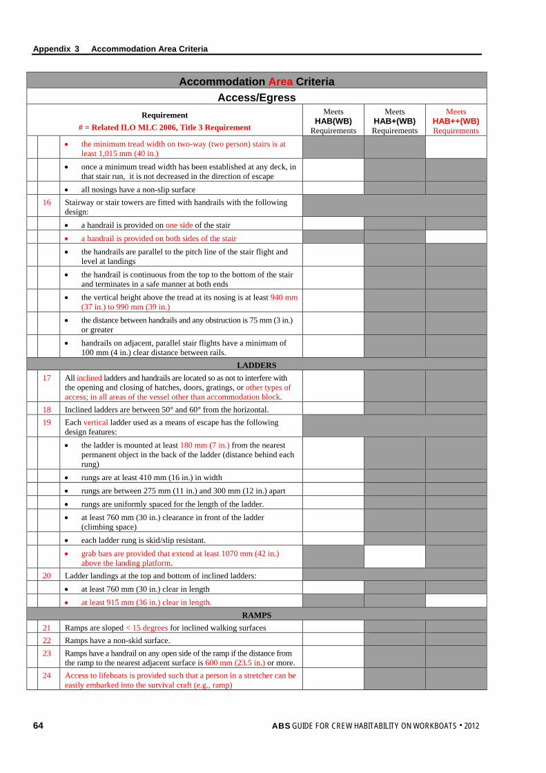
Appendix 3 Accommodation Area Criteria
64 ABS GUIDE FOR CREW HABITABILITY ON WORKBOATS . 2012
Accommodation Area Criteria Access/Egress
Requirement # = Related ILO MLC 2006, Title 3 Requirement
Meets HAB(WB)
Requirements
Meets HAB+(WB) Requirements
Meets HAB++(WB) Requirements
• the minimum tread width on two-way (two person) stairs is at least 1,015 mm (40 in.)
• once a minimum tread width has been established at any deck, in that stair run, it is not decreased in the direction of escape
• all nosings have a non-slip surface 16 Stairway or stair towers are fitted with handrails with the following
design:
• a handrail is provided on one side of the stair • a handrail is provided on both sides of the stair • the handrails are parallel to the pitch line of the stair flight and
level at landings
• the handrail is continuous from the top to the bottom of the stair and terminates in a safe manner at both ends
• the vertical height above the tread at its nosing is at least 940 mm (37 in.) to 990 mm (39 in.)
• the distance between handrails and any obstruction is 75 mm (3 in.) or greater
• handrails on adjacent, parallel stair flights have a minimum of 100 mm (4 in.) clear distance between rails.
LADDERS 17 All inclined ladders and handrails are located so as not to interfere with
the opening and closing of hatches, doors, gratings, or other types of access; in all areas of the vessel other than accommodation block.
18 Inclined ladders are between 50° and 60° from the horizontal. 19 Each vertical ladder used as a means of escape has the following
design features:
• the ladder is mounted at least 180 mm (7 in.) from the nearest permanent object in the back of the ladder (distance behind each rung)
• rungs are at least 410 mm (16 in.) in width • rungs are between 275 mm (11 in.) and 300 mm (12 in.) apart • rungs are uniformly spaced for the length of the ladder. • at least 760 mm (30 in.) clearance in front of the ladder
(climbing space)
• each ladder rung is skid/slip resistant. • grab bars are provided that extend at least 1070 mm (42 in.)
above the landing platform.
20 Ladder landings at the top and bottom of inclined ladders: • at least 760 mm (30 in.) clear in length • at least 915 mm (36 in.) clear in length.
RAMPS 21 Ramps are sloped < 15 degrees for inclined walking surfaces 22 Ramps have a non-skid surface. 23 Ramps have a handrail on any open side of the ramp if the distance from
the ramp to the nearest adjacent surface is 600 mm (23.5 in.) or more.
24 Access to lifeboats is provided such that a person in a stretcher can be easily embarked into the survival craft (e.g., ramp)
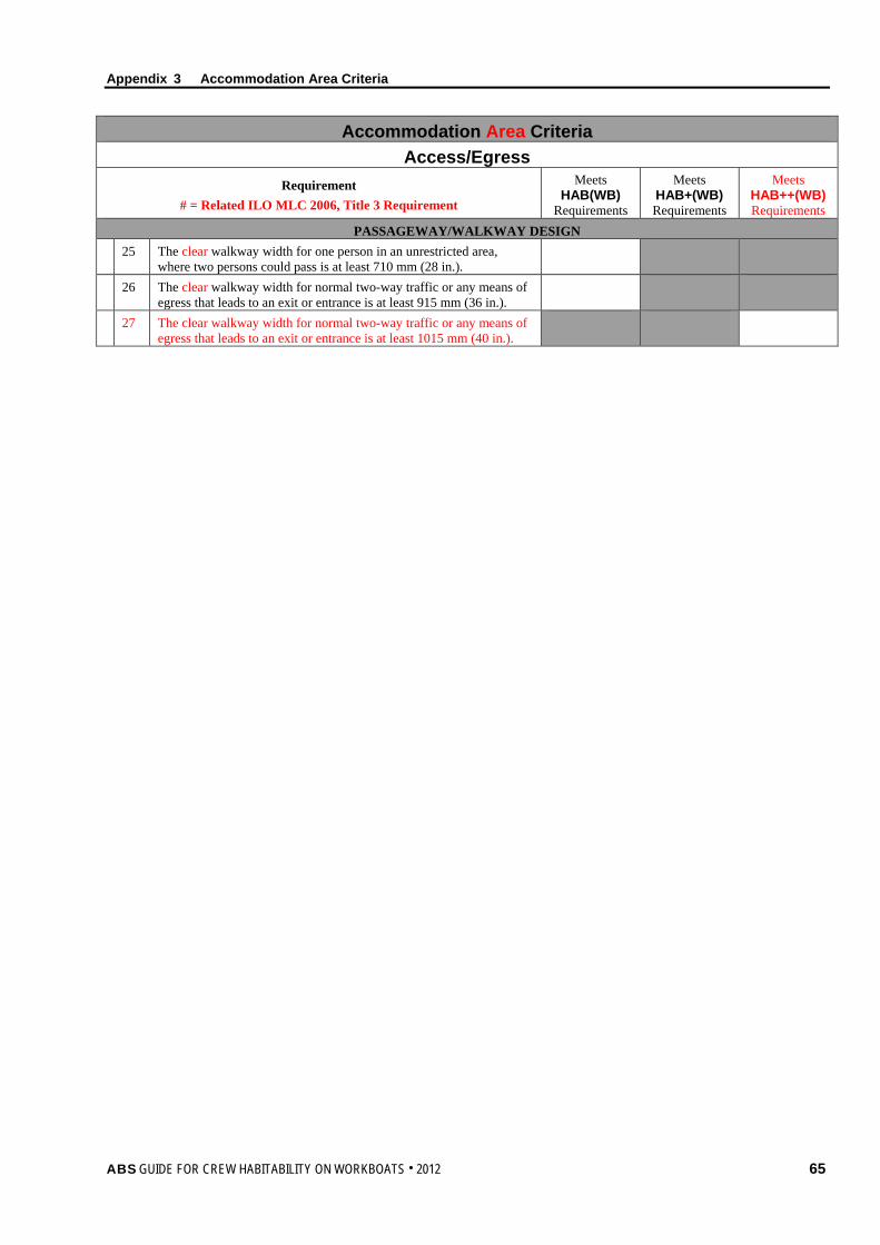
Appendix 3 Accommodation Area Criteria
ABS GUIDE FOR CREW HABITABILITY ON WORKBOATS . 2012 65
Accommodation Area Criteria Access/Egress
Requirement # = Related ILO MLC 2006, Title 3 Requirement
Meets HAB(WB)
Requirements
Meets HAB+(WB) Requirements
Meets HAB++(WB) Requirements
PASSAGEWAY/WALKWAY DESIGN 25 The clear walkway width for one person in an unrestricted area,
where two persons could pass is at least 710 mm (28 in.).
26 The clear walkway width for normal two-way traffic or any means of egress that leads to an exit or entrance is at least 915 mm (36 in.).
27 The clear walkway width for normal two-way traffic or any means of egress that leads to an exit or entrance is at least 1015 mm (40 in.).
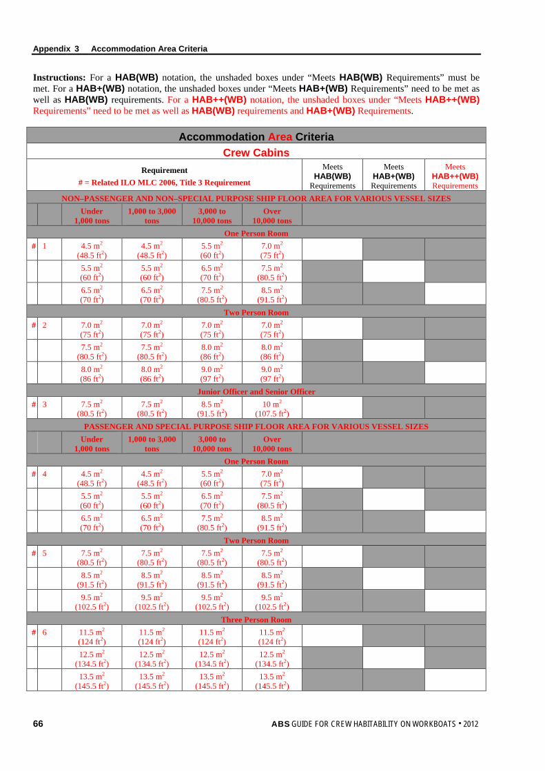
Appendix 3 Accommodation Area Criteria
66 ABS GUIDE FOR CREW HABITABILITY ON WORKBOATS . 2012
Instructions: For a HAB(WB) notation, the unshaded boxes under “Meets HAB(WB) Requirements” must be met. For a HAB+(WB) notation, the unshaded boxes under “Meets HAB+(WB) Requirements” need to be met as well as HAB(WB) requirements. For a HAB++(WB) notation, the unshaded boxes under “Meets HAB++(WB) Requirements” need to be met as well as HAB(WB) requirements and HAB+(WB) Requirements.
Accommodation Area Criteria Crew Cabins
Requirement # = Related ILO MLC 2006, Title 3 Requirement
Meets HAB(WB)
Requirements
Meets HAB+(WB) Requirements
Meets HAB++(WB) Requirements
NON–PASSENGER AND NON–SPECIAL PURPOSE SHIP FLOOR AREA FOR VARIOUS VESSEL SIZES
Under 1,000 tons
1,000 to 3,000 tons
3,000 to 10,000 tons
Over 10,000 tons
One Person Room # 1 4.5 m2
(48.5 ft2) 4.5 m2
(48.5 ft2) 5.5 m2 (60 ft2)
7.0 m2 (75 ft2)
5.5 m2 (60 ft2)
5.5 m2 (60 ft2)
6.5 m2 (70 ft2)
7.5 m2 (80.5 ft2)
6.5 m2 (70 ft2)
6.5 m2 (70 ft2)
7.5 m2 (80.5 ft2)
8.5 m2 (91.5 ft2)
Two Person Room # 2 7.0 m2
(75 ft2) 7.0 m2 (75 ft2)
7.0 m2 (75 ft2)
7.0 m2 (75 ft2)
7.5 m2 (80.5 ft2)
7.5 m2 (80.5 ft2)
8.0 m2 (86 ft2)
8.0 m2 (86 ft2)
8.0 m2 (86 ft2)
8.0 m2 (86 ft2)
9.0 m2 (97 ft2)
9.0 m2 (97 ft2)
Junior Officer and Senior Officer # 3 7.5 m2
(80.5 ft2) 7.5 m2
(80.5 ft2) 8.5 m2
(91.5 ft2) 10 m2
(107.5 ft2)
PASSENGER AND SPECIAL PURPOSE SHIP FLOOR AREA FOR VARIOUS VESSEL SIZES
Under 1,000 tons
1,000 to 3,000 tons
3,000 to 10,000 tons
Over 10,000 tons
One Person Room # 4 4.5 m2
(48.5 ft2) 4.5 m2
(48.5 ft2) 5.5 m2 (60 ft2)
7.0 m2 (75 ft2)
5.5 m2 (60 ft2)
5.5 m2 (60 ft2)
6.5 m2 (70 ft2)
7.5 m2 (80.5 ft2)
6.5 m2 (70 ft2)
6.5 m2 (70 ft2)
7.5 m2 (80.5 ft2)
8.5 m2 (91.5 ft2)
Two Person Room # 5 7.5 m2
(80.5 ft2) 7.5 m2
(80.5 ft2) 7.5 m2
(80.5 ft2) 7.5 m2
(80.5 ft2)
8.5 m2 (91.5 ft2)
8.5 m2 (91.5 ft2)
8.5 m2 (91.5 ft2)
8.5 m2 (91.5 ft2)
9.5 m2 (102.5 ft2)
9.5 m2 (102.5 ft2)
9.5 m2 (102.5 ft2)
9.5 m2 (102.5 ft2)
Three Person Room # 6 11.5 m2
(124 ft2) 11.5 m2 (124 ft2)
11.5 m2 (124 ft2)
11.5 m2 (124 ft2)
12.5 m2 (134.5 ft2)
12.5 m2 (134.5 ft2)
12.5 m2 (134.5 ft2)
12.5 m2 (134.5 ft2)
13.5 m2 (145.5 ft2)
13.5 m2 (145.5 ft2)
13.5 m2 (145.5 ft2)
13.5 m2 (145.5 ft2)
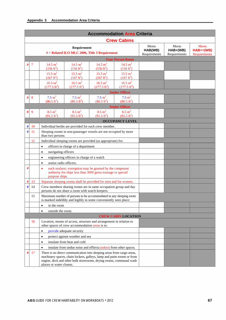
Appendix 3 Accommodation Area Criteria
ABS GUIDE FOR CREW HABITABILITY ON WORKBOATS . 2012 67
Accommodation Area Criteria Crew Cabins
Requirement # = Related ILO MLC 2006, Title 3 Requirement
Meets HAB(WB)
Requirements
Meets HAB+(WB) Requirements
Meets HAB++(WB) Requirements
Four Person Room # 7 14.5 m2
(156 ft2) 14.5 m2 (156 ft2)
14.5 m2 (156 ft2)
14.5 m2 (156 ft2)
15.5 m2 (167 ft2)
15.5 m2 (167 ft2)
15.5 m2 (167 ft2)
15.5 m2 (167 ft2)
16.5 m2 (177.5 ft2)
16.5 m2 (177.5 ft2)
16.5 m2 (177.5 ft2)
16.5 m2 (177.5 ft2)
Junior Officer # 8 7.5 m2
(80.5 ft2) 7.5 m2
(80.5 ft2) 7.5 m2
(80.5 ft2) 7.5 m2
(80.5 ft2)
Senior Officer # 9 8.5 m2
(91.5 ft2) 8.5 m2
(91.5 ft2) 8.5 m2
(91.5 ft2) 8.5 m2
(91.5 ft2)
OCCUPANCY LEVEL # 10 Individual berths are provided for each crew member. # 11 Sleeping rooms in non-passenger vessels are not occupied by more
than two persons
12 Individual sleeping rooms are provided (as appropriate) for: • officers in charge of a department • navigating officers • engineering officers in charge of a watch • senior radio officers. # • each seafarer, exemption may be granted by the competent
authority for ships less than 3000 gross tonnage or special purpose ships
# 13 Separate sleeping rooms shall be provided for men and for women. # 14 Crew members sharing rooms are in same occupation group and day
persons do not share a room with watch-keepers.
15 Maximum number of persons to be accommodated in any sleeping room is marked indelibly and legibly in some conveniently seen place:
• in the room • outside the room.
CREW CABIN LOCATION 16 Location, means of access, structure and arrangement in relation to
other spaces of crew accommodation areas is to:
• provide adequate security • protect against weather and sea • insulate from heat and cold • insulate from undue noise and effluvia (odors) from other spaces. # 17 There is no direct communication into sleeping areas from cargo areas,
machinery spaces, chain lockers, galleys, lamp and paint rooms or from engine, deck and other bulk storerooms, drying rooms, communal wash places or water closets.
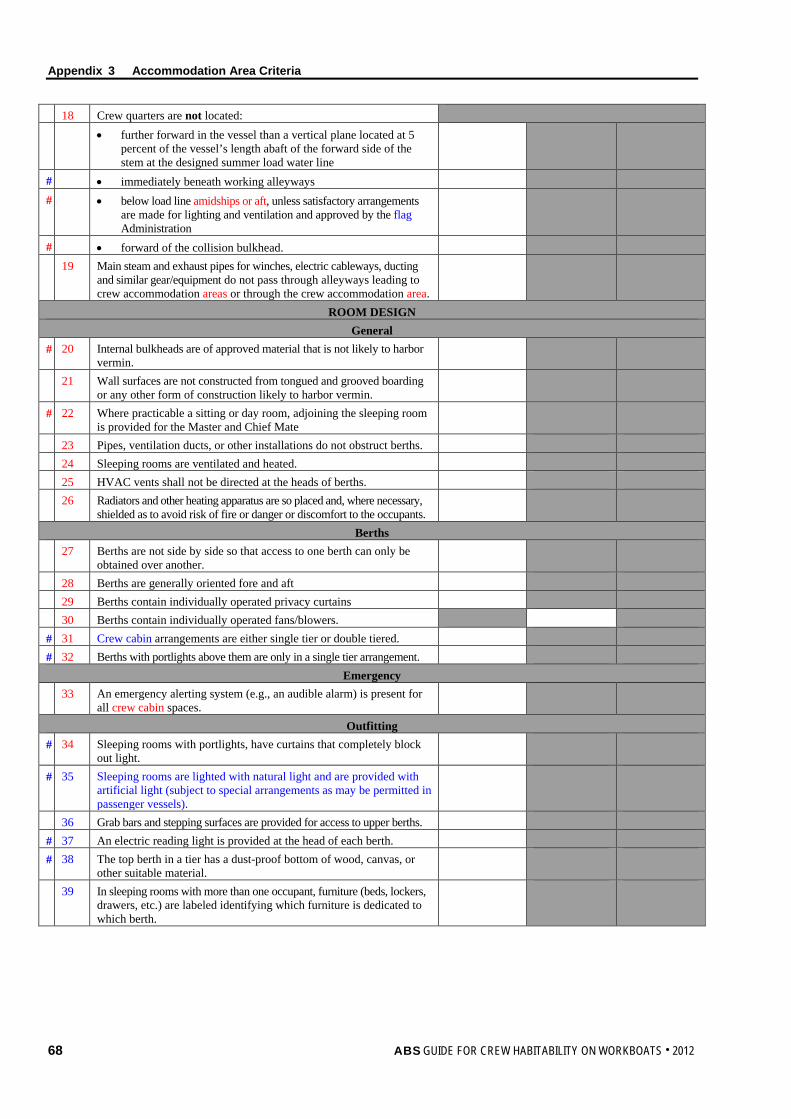
Appendix 3 Accommodation Area Criteria
68 ABS GUIDE FOR CREW HABITABILITY ON WORKBOATS . 2012
18 Crew quarters are not located: • further forward in the vessel than a vertical plane located at 5
percent of the vessel’s length abaft of the forward side of the stem at the designed summer load water line
# • immediately beneath working alleyways # • below load line amidships or aft, unless satisfactory arrangements
are made for lighting and ventilation and approved by the flag Administration
# • forward of the collision bulkhead. 19 Main steam and exhaust pipes for winches, electric cableways, ducting
and similar gear/equipment do not pass through alleyways leading to crew accommodation areas or through the crew accommodation area.
ROOM DESIGN General
# 20 Internal bulkheads are of approved material that is not likely to harbor vermin.
21 Wall surfaces are not constructed from tongued and grooved boarding or any other form of construction likely to harbor vermin.
# 22 Where practicable a sitting or day room, adjoining the sleeping room is provided for the Master and Chief Mate
23 Pipes, ventilation ducts, or other installations do not obstruct berths. 24 Sleeping rooms are ventilated and heated. 25 HVAC vents shall not be directed at the heads of berths. 26 Radiators and other heating apparatus are so placed and, where necessary,
shielded as to avoid risk of fire or danger or discomfort to the occupants.
Berths 27 Berths are not side by side so that access to one berth can only be
obtained over another.
28 Berths are generally oriented fore and aft 29 Berths contain individually operated privacy curtains 30 Berths contain individually operated fans/blowers. # 31 Crew cabin arrangements are either single tier or double tiered. # 32 Berths with portlights above them are only in a single tier arrangement.
Emergency 33 An emergency alerting system (e.g., an audible alarm) is present for
all crew cabin spaces.
Outfitting # 34 Sleeping rooms with portlights, have curtains that completely block
out light.
# 35 Sleeping rooms are lighted with natural light and are provided with artificial light (subject to special arrangements as may be permitted in passenger vessels).
36 Grab bars and stepping surfaces are provided for access to upper berths. # 37 An electric reading light is provided at the head of each berth. # 38 The top berth in a tier has a dust-proof bottom of wood, canvas, or
other suitable material.
39 In sleeping rooms with more than one occupant, furniture (beds, lockers, drawers, etc.) are labeled identifying which furniture is dedicated to which berth.
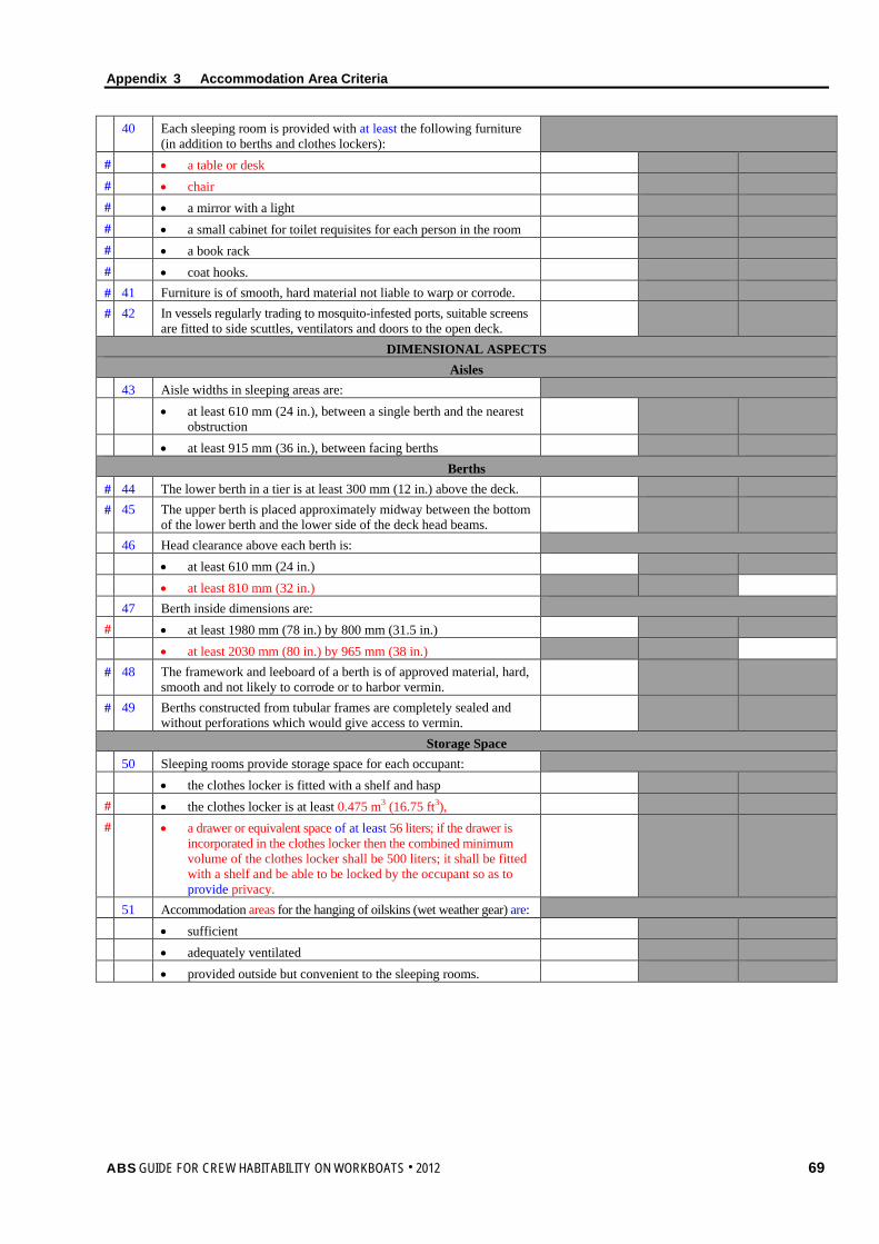
Appendix 3 Accommodation Area Criteria
ABS GUIDE FOR CREW HABITABILITY ON WORKBOATS . 2012 69
40 Each sleeping room is provided with at least the following furniture (in addition to berths and clothes lockers):
# • a table or desk # • chair # • a mirror with a light # • a small cabinet for toilet requisites for each person in the room # • a book rack # • coat hooks. # 41 Furniture is of smooth, hard material not liable to warp or corrode. # 42 In vessels regularly trading to mosquito-infested ports, suitable screens
are fitted to side scuttles, ventilators and doors to the open deck.
DIMENSIONAL ASPECTS Aisles
43 Aisle widths in sleeping areas are: • at least 610 mm (24 in.), between a single berth and the nearest
obstruction
• at least 915 mm (36 in.), between facing berths Berths
# 44 The lower berth in a tier is at least 300 mm (12 in.) above the deck. # 45 The upper berth is placed approximately midway between the bottom
of the lower berth and the lower side of the deck head beams.
46 Head clearance above each berth is: • at least 610 mm (24 in.) • at least 810 mm (32 in.) 47 Berth inside dimensions are: # • at least 1980 mm (78 in.) by 800 mm (31.5 in.) • at least 2030 mm (80 in.) by 965 mm (38 in.) # 48 The framework and leeboard of a berth is of approved material, hard,
smooth and not likely to corrode or to harbor vermin.
# 49 Berths constructed from tubular frames are completely sealed and without perforations which would give access to vermin.
Storage Space 50 Sleeping rooms provide storage space for each occupant: • the clothes locker is fitted with a shelf and hasp # • the clothes locker is at least 0.475 m3 (16.75 ft3), # • a drawer or equivalent space of at least 56 liters; if the drawer is
incorporated in the clothes locker then the combined minimum volume of the clothes locker shall be 500 liters; it shall be fitted with a shelf and be able to be locked by the occupant so as to provide privacy.
51 Accommodation areas for the hanging of oilskins (wet weather gear) are: • sufficient • adequately ventilated • provided outside but convenient to the sleeping rooms.
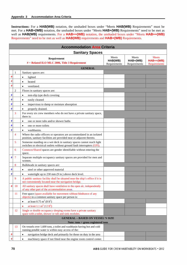
Appendix 3 Accommodation Area Criteria
70 ABS GUIDE FOR CREW HABITABILITY ON WORKBOATS . 2012
Instructions: For a HAB(WB) notation, the unshaded boxes under “Meets HAB(WB) Requirements” must be met. For a HAB+(WB) notation, the unshaded boxes under “Meets HAB+(WB) Requirements” need to be met as well as HAB(WB) requirements. For a HAB++(WB) notation, the unshaded boxes under “Meets HAB++(WB) Requirements” need to be met as well as HAB(WB) requirements and HAB+(WB) Requirements.
Accommodation Area Criteria Sanitary Spaces
Requirement # = Related ILO MLC 2006, Title 3 Requirement
Meets HAB(WB)
Requirements
Meets HAB+(WB) Requirements
Meets HAB++(WB) Requirements
GENERAL 1 Sanitary spaces are: # • lighted # • heated # • ventilated. 2 Floors in sanitary spaces are: # • non-slip type deck covering # • easily cleaned # • impervious to damp or moisture absorption # • properly drained. 3 For every six crew members who do not have a private sanitary space,
there is:
# • one or more tubs and/or shower baths # • one or more toilets # • washbasins. 4 Where the radio officers or operators are accommodated in an isolated
position, sanitary facilities are provided near or adjacent thereto.
5 Someone standing on a wet deck in sanitary spaces cannot reach light switches or electrical outlets without ground fault interrupters (GFI).
6 Common/Shared spaces are gender identifiable without entering the space.
# 7 Separate multiple occupancy sanitary spaces are provided for men and women.
8 Bulkheads in sanitary spaces are: # • steel or other approved material # • watertight up to 230 mm (9 in.) above deck level. 9 A public sanitary facility shall be situated near the ship’s office if it is
not conveniently located near the navigation bridge.
# 10 All sanitary spaces shall have ventilation to the open air, independently of any other part of the accommodation areas.
11 Free space (space available for movement without hindrance of any objects) in a common sanitary space per person is:
• at least 0.75 m2 (8 ft2) • at least 1.1 m2 (12 ft2) 12 Single or double occupancy sleeping rooms have a private sanitary
space with a toilet, shower or tub and sink modules.
GENERAL – BASED ON VESSEL’S SIZE Note: tons = gross registered tons
13 On vessels over 1,600 tons, a toilet and washbasin having hot and cold running potable water is within easy access of the:
# • navigation bridge deck and primarily for those on duty in the area # • machinery space if not fitted near the engine room control center.
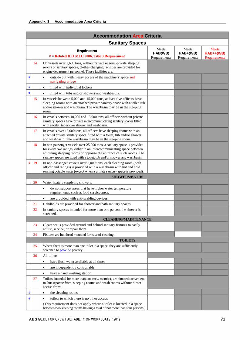
Appendix 3 Accommodation Area Criteria
ABS GUIDE FOR CREW HABITABILITY ON WORKBOATS . 2012 71
Accommodation Area Criteria Sanitary Spaces
Requirement # = Related ILO MLC 2006, Title 3 Requirement
Meets HAB(WB)
Requirements
Meets HAB+(WB) Requirements
Meets HAB++(WB) Requirements
14 On vessels over 1,600 tons, without private or semi-private sleeping rooms or sanitary spaces, clothes changing facilities are provided for engine department personnel. These facilities are:
# • outside but within easy access of the machinery space and navigating bridge
# • fitted with individual lockers # • fitted with tubs and/or showers and washbasins. 15 In vessels between 5,000 and 15,000 tons, at least five officers have
sleeping rooms with an attached private sanitary space with a toilet, tub and/or shower and washbasin. The washbasin may be in the sleeping room.
16 In vessels between 10,000 and 15,000 tons, all officers without private sanitary spaces have private intercommunicating sanitary spaces fitted with a toilet, tub and/or shower and washbasin.
17 In vessels over 15,000 tons, all officers have sleeping rooms with an attached private sanitary space fitted with a toilet, tub and/or shower and washbasin. The washbasin may be in the sleeping room.
18 In non-passenger vessels over 25,000 tons, a sanitary space is provided for every two ratings, either in an intercommunicating space between adjoining sleeping rooms or opposite the entrance of such rooms. The sanitary spaces are fitted with a toilet, tub and/or shower and washbasin.
# 19 In non-passenger vessels over 5,000 tons, each sleeping room (both officer and ratings) is provided with a washbasin with hot and cold running potable water (except when a private sanitary space is provided).
SHOWERS/BATHS 20 Water heaters supplying showers: • do not support areas that have higher water temperature
requirements, such as food service areas
• are provided with anti-scalding devices. 21 Handholds are provided for shower and bath sanitary spaces. 22 In sanitary spaces intended for more than one person, the shower is
screened.
CLEANING/MAINTENANCE 23 Clearance is provided around and behind sanitary fixtures to easily
adjust, service, or repair them
24 Fixtures are bulkhead mounted for ease of cleaning. TOILETS
25 Where there is more than one toilet in a space, they are sufficiently screened to provide privacy.
26 All toilets: • have flush water available at all times • are independently controllable • have a hand washing station. 27 Toilets, intended for more than one crew member, are situated convenient
to, but separate from, sleeping rooms and wash rooms without direct access from:
# • the sleeping rooms # • toilets to which there is no other access.
(This requirement does not apply where a toilet is located in a space between two sleeping rooms having a total of not more than four persons.)
Appendix 3 Accommodation Area Criteria
72 ABS GUIDE FOR CREW HABITABILITY ON WORKBOATS . 2012
Accommodation Area Criteria Sanitary Spaces
Requirement # = Related ILO MLC 2006, Title 3 Requirement
Meets HAB(WB)
Requirements
Meets HAB+(WB) Requirements
Meets HAB++(WB) Requirements
# 28 All toilets have ventilation to the open air, independent of any other part of the space.
29 All toilet spaces shall be ventilated sufficiently to be reasonably free of disagreeable odors and condensation.
30 The following minimum number of separate toilets are provided: • 3 in vessels under 800 tons • 4 in vessels 800 tons or over but under 3,000 tons • 6 in vessels 3,000 tons or over.
WASHBASINS 31 Water heaters supplying washbasins:
• do not support areas that have higher water temperature requirements
• are provided with anti-scalding devices. 32 The following at a minimum are provided for each washbasin: • a mirror with light • toiletry shelf • electrical outlets that crew members have ready access to are
equipped with ground fault interrupters (GFI)
33 Facilities to dry hands are provided at all washbasins. 34 Washbasins are: • constructed of approved material • smooth surfaced • not liable to crack, flake or corrode.
URINALS 35 Urinals have privacy partitions between units and at the end of rows if
not provided by sanitary space structures.
36 The dimension between the centerline of two urinals side-by-side is 690 mm (27 in.) or greater.
37 The dimension between the centerline of a urinal and bulkhead next to the urinal is 380 mm (15 in.) or greater.
38 The height of the front edge of a urinal is between 455 mm (18 in.) and 605 mm (24 in.) above the deck surface
Appendix 3 Accommodation Area Criteria
ABS GUIDE FOR CREW HABITABILITY ON WORKBOATS . 2012 73
Instructions: For a HAB(WB) notation, the unshaded boxes under “Meets HAB(WB) Requirements” must be met. For a HAB+(WB) notation, the unshaded boxes under “Meets HAB+(WB) Requirements” need to be met as well as HAB(WB) requirements. For a HAB++(WB) notation, the unshaded boxes under “Meets HAB++(WB) Requirements” need to be met as well as HAB(WB) requirements and HAB+(WB) Requirements.
Accommodation Area Criteria Office
Requirement # = Related ILO MLC 2006, Title 3 Requirement
Meets HAB(WB)
Requirements
Meets HAB+(WB) Requirements
Meets HAB++(WB) Requirements
GENERAL 1 In vessels of over 3000 tons: # • One room is provided and equipped for use as an office for the
deck department
# • One room is provided and equipped for use as an office for the engine department.
OUTFITTING 2 The vessel’s office has a toilet and washbasin in close proximity.
Appendix 3 Accommodation Area Criteria
74 ABS GUIDE FOR CREW HABITABILITY ON WORKBOATS . 2012
Instructions: For a HAB(WB) notation, the unshaded boxes under “Meets HAB(WB) Requirements” must be met. For a HAB+(WB) notation, the unshaded boxes under “Meets HAB+(WB) Requirements” need to be met as well as HAB(WB) requirements. For a HAB++(WB) notation, the unshaded boxes under “Meets HAB++(WB) Requirements” need to be met as well as HAB(WB) requirements and HAB+(WB) Requirements.
Accommodation Area Criteria Food Service Areas
Requirement # = Related ILO MLC 2006, Title 3 Requirement
Meets HAB(WB)
Requirements
Meets HAB+(WB) Requirements
Meets HAB++(WB) Requirements
GENERAL 1 Access is provided to all areas requiring cleaning, painting, or treating
with pesticide/insecticide.
2 There are no crevices or inaccessible voids, which might harbor vermin, cooking or food waste, or other extraneous matter.
3 Places where food is prepared, served or stored are not used as sleeping areas.
4 Deck drains are provided in all food service areas subject to flood type cleaning or where normal operations release or discharge water or other liquid onto the deck.
5 Deck drains for food service areas are provided in number and location so that complete drainage is possible under normal conditions of list and trim.
6 Distributive systems such as piping, wiring and HVAC ducts are minimized in food service areas.
7 Where distributive systems are located in food service areas, they are installed as close as practicable to the overhead in order to provide maximum headroom.
8 Flow of food through vessel: • is arranged in logical sequence that minimizes cross-traffic or
backtracking
• allows for adequate separation of clean and soiled operations. FOOD SERVICE DOORS
9 Toilet room doors opening directly into food preparation or serving areas are self-closing and tight.
FOOD SERVICE PASSAGEWAYS 10 The passage width between storage shelves is at least 710 mm (28 in.).
MESS ROOM General
11 Mess rooms are: # • located apart from sleeping rooms • adequately ventilated • adequately insulated to prevent condensation or overheating # • located as near to the galley as is practicable except where the
mess room is equipped with a steam table.
# 12 Mess rooms have tables and seats sufficient for the number of persons likely to use them at any one time.
13 Mess lines and mess rooms are protected from weather, objectionable sights (such as garbage disposal areas) and objectionable odors (such as from engines, holds, toilets, fire room, etc.).
# 14 Lighting in mess rooms is provided by means of natural light and artificial light (subject to special arrangements as may be permitted in passenger vessels).
Appendix 3 Accommodation Area Criteria
ABS GUIDE FOR CREW HABITABILITY ON WORKBOATS . 2012 75
Accommodation Area Criteria Food Service Areas
Requirement # = Related ILO MLC 2006, Title 3 Requirement
Meets HAB(WB)
Requirements
Meets HAB+(WB) Requirements
Meets HAB++(WB) Requirements
15 The following is available for crew use at all times: # • refrigerator # • facilities for hot beverages # • facilities for cool water. 16 In vessels less than 1,000 tons, two sufficient separate mess room
accommodation areas are provided for:
# • master and officers # • petty officers and other ratings Note: Please refer to flag State requirements for applicability of
separate mess rooms.
17 In vessels greater than 1,000 tons, three sufficient separate mess room accommodation areas are provided for:
• master and officers • engine department petty officers and other ratings • deck department petty officers and other ratings Note: Please refer to flag State requirements for applicability of
separate mess rooms.
18 The tops of tables and seating are capable of being easily cleaned. # 19 Where available pantries are not accessible to mess rooms, adequate
lockers for mess utensils and proper facilities for washing utensils are provided.
Outfitting 20 A transparent sanitation shield is installed to completely shield the entire
length of the food serving lines if provided with a tray slide or rail.
21 Tray slides (or rails) if provided are placed along food and beverage serving lines.
22 Adequate lockers for mess utensils are provided. MESS ROOM DIMENSIONAL ASPECTS
23 Table space for each diner is: • at least 610 mm (24 in.) wide by 380 mm (15 in.) deep • at least 740 mm (29 in.) wide by 430 mm (17 in.) deep 24 Distance between tables with back to back seating is: • at least 1195 mm (47 in.) • at least 1525 mm (60 in.) 25 Deck area requirements for planned seating capacity are: # • at least 1.5 m2 (16.2 ft2) per person • at least 1.7 m2 (18.4 ft2) per person • at least 1.9 m2 (20.5 ft2) per person
GALLEY/SCULLERY General
26 Ice making facilities for at least 0.57 kg (1.25 pounds) of ice per person per day are provided.
27 Toilet and washbasin facilities are of suitable design and provide hand washing stations so that no crew member must walk more than 7.5 m (25 ft) to a station. Slop sinks and scullery sinks are not satisfactory hand washing stations.
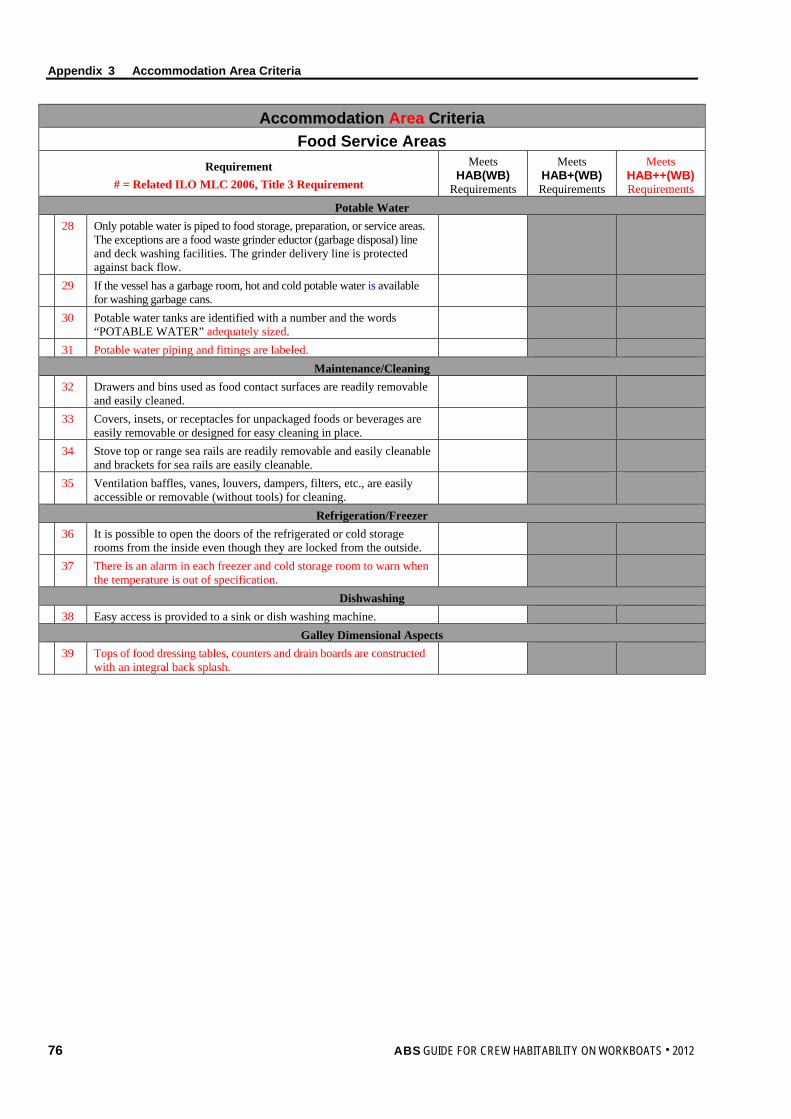
Appendix 3 Accommodation Area Criteria
76 ABS GUIDE FOR CREW HABITABILITY ON WORKBOATS . 2012
Accommodation Area Criteria Food Service Areas
Requirement # = Related ILO MLC 2006, Title 3 Requirement
Meets HAB(WB)
Requirements
Meets HAB+(WB) Requirements
Meets HAB++(WB) Requirements
Potable Water 28 Only potable water is piped to food storage, preparation, or service areas.
The exceptions are a food waste grinder eductor (garbage disposal) line and deck washing facilities. The grinder delivery line is protected against back flow.
29 If the vessel has a garbage room, hot and cold potable water is available for washing garbage cans.
30 Potable water tanks are identified with a number and the words “POTABLE WATER” adequately sized.
31 Potable water piping and fittings are labeled. Maintenance/Cleaning
32 Drawers and bins used as food contact surfaces are readily removable and easily cleaned.
33 Covers, insets, or receptacles for unpackaged foods or beverages are easily removable or designed for easy cleaning in place.
34 Stove top or range sea rails are readily removable and easily cleanable and brackets for sea rails are easily cleanable.
35 Ventilation baffles, vanes, louvers, dampers, filters, etc., are easily accessible or removable (without tools) for cleaning.
Refrigeration/Freezer 36 It is possible to open the doors of the refrigerated or cold storage
rooms from the inside even though they are locked from the outside.
37 There is an alarm in each freezer and cold storage room to warn when the temperature is out of specification.
Dishwashing 38 Easy access is provided to a sink or dish washing machine.
Galley Dimensional Aspects 39 Tops of food dressing tables, counters and drain boards are constructed
with an integral back splash.
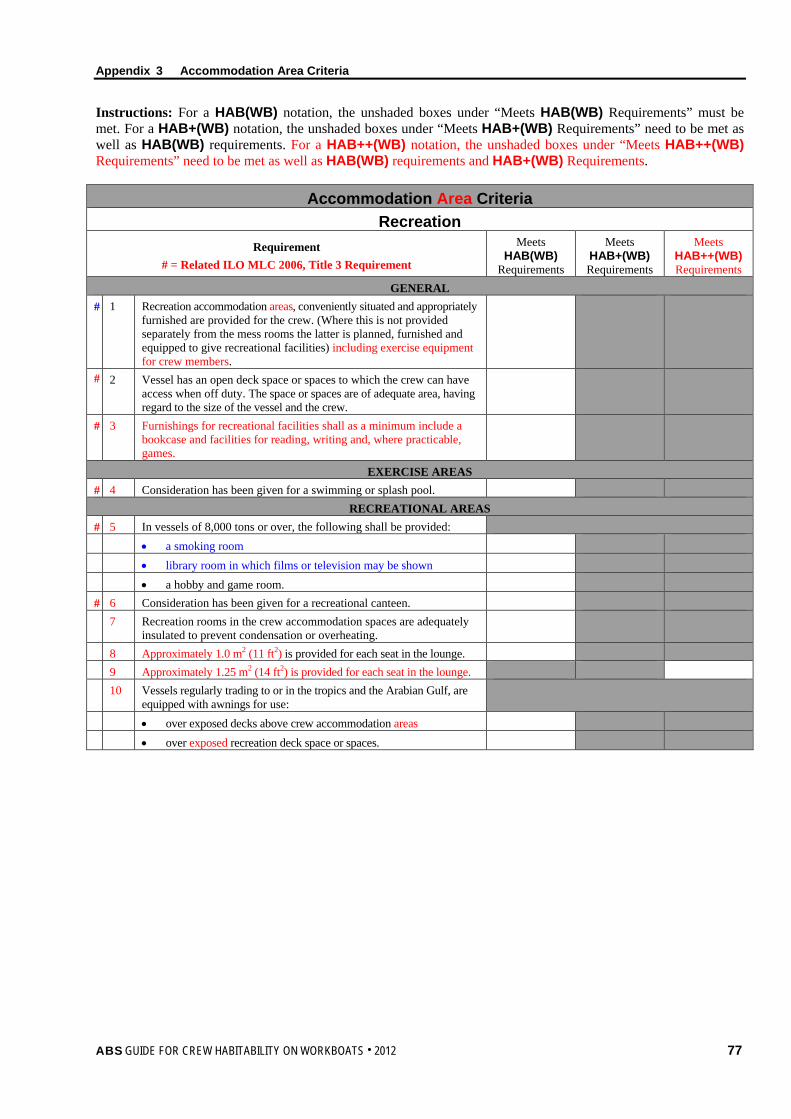
Appendix 3 Accommodation Area Criteria
ABS GUIDE FOR CREW HABITABILITY ON WORKBOATS . 2012 77
Instructions: For a HAB(WB) notation, the unshaded boxes under “Meets HAB(WB) Requirements” must be met. For a HAB+(WB) notation, the unshaded boxes under “Meets HAB+(WB) Requirements” need to be met as well as HAB(WB) requirements. For a HAB++(WB) notation, the unshaded boxes under “Meets HAB++(WB) Requirements” need to be met as well as HAB(WB) requirements and HAB+(WB) Requirements.
Accommodation Area Criteria Recreation
Requirement # = Related ILO MLC 2006, Title 3 Requirement
Meets HAB(WB)
Requirements
Meets HAB+(WB) Requirements
Meets HAB++(WB) Requirements
GENERAL # 1 Recreation accommodation areas, conveniently situated and appropriately
furnished are provided for the crew. (Where this is not provided separately from the mess rooms the latter is planned, furnished and equipped to give recreational facilities) including exercise equipment for crew members.
# 2 Vessel has an open deck space or spaces to which the crew can have access when off duty. The space or spaces are of adequate area, having regard to the size of the vessel and the crew.
# 3 Furnishings for recreational facilities shall as a minimum include a bookcase and facilities for reading, writing and, where practicable, games.
EXERCISE AREAS # 4 Consideration has been given for a swimming or splash pool.
RECREATIONAL AREAS # 5 In vessels of 8,000 tons or over, the following shall be provided: • a smoking room • library room in which films or television may be shown • a hobby and game room. # 6 Consideration has been given for a recreational canteen. 7 Recreation rooms in the crew accommodation spaces are adequately
insulated to prevent condensation or overheating.
8 Approximately 1.0 m2 (11 ft2) is provided for each seat in the lounge. 9 Approximately 1.25 m2 (14 ft2) is provided for each seat in the lounge. 10 Vessels regularly trading to or in the tropics and the Arabian Gulf, are
equipped with awnings for use:
• over exposed decks above crew accommodation areas • over exposed recreation deck space or spaces.
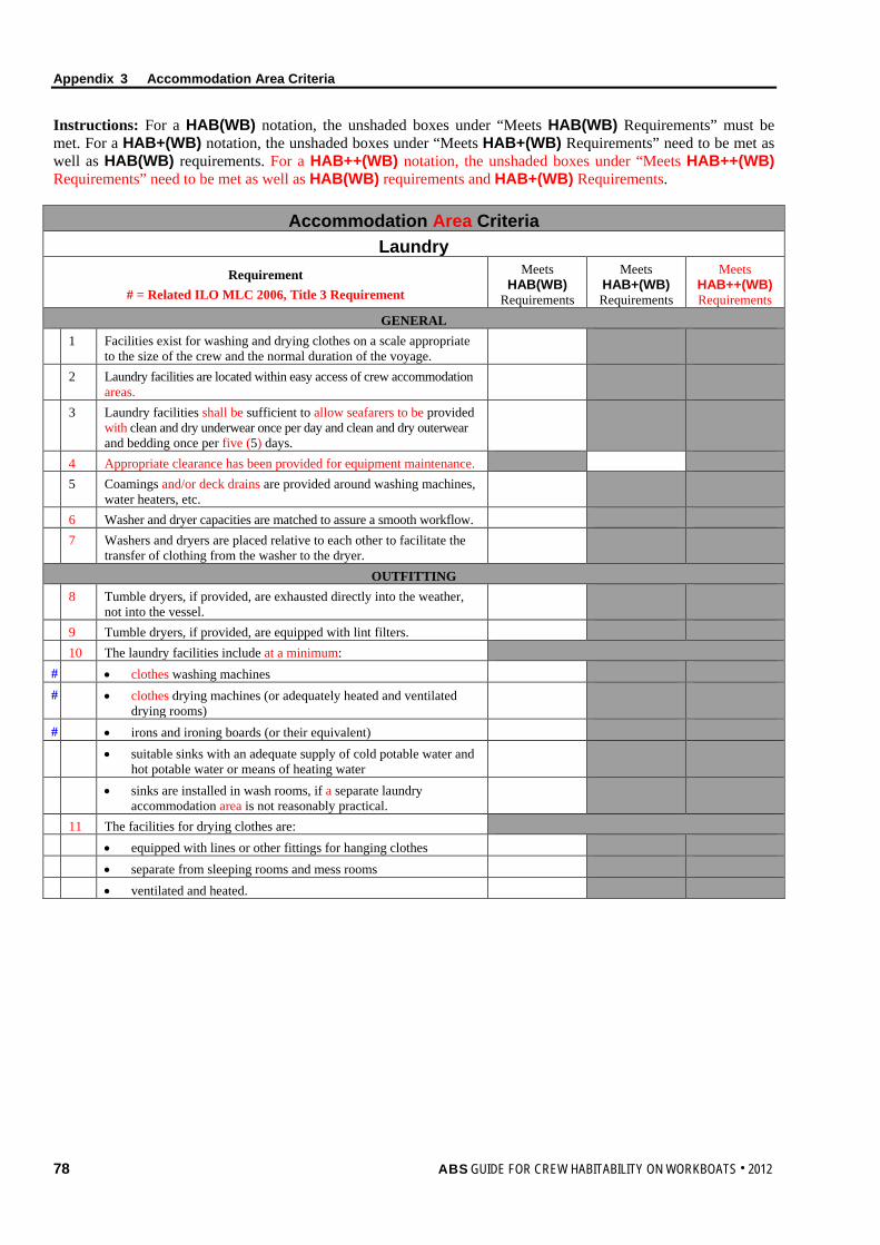
Appendix 3 Accommodation Area Criteria
78 ABS GUIDE FOR CREW HABITABILITY ON WORKBOATS . 2012
Instructions: For a HAB(WB) notation, the unshaded boxes under “Meets HAB(WB) Requirements” must be met. For a HAB+(WB) notation, the unshaded boxes under “Meets HAB+(WB) Requirements” need to be met as well as HAB(WB) requirements. For a HAB++(WB) notation, the unshaded boxes under “Meets HAB++(WB) Requirements” need to be met as well as HAB(WB) requirements and HAB+(WB) Requirements.
Accommodation Area Criteria Laundry
Requirement # = Related ILO MLC 2006, Title 3 Requirement
Meets HAB(WB)
Requirements
Meets HAB+(WB) Requirements
Meets HAB++(WB) Requirements
GENERAL 1 Facilities exist for washing and drying clothes on a scale appropriate
to the size of the crew and the normal duration of the voyage.
2 Laundry facilities are located within easy access of crew accommodation areas.
3 Laundry facilities shall be sufficient to allow seafarers to be provided with clean and dry underwear once per day and clean and dry outerwear and bedding once per five (5) days.
4 Appropriate clearance has been provided for equipment maintenance. 5 Coamings and/or deck drains are provided around washing machines,
water heaters, etc.
6 Washer and dryer capacities are matched to assure a smooth workflow. 7 Washers and dryers are placed relative to each other to facilitate the
transfer of clothing from the washer to the dryer.
OUTFITTING 8 Tumble dryers, if provided, are exhausted directly into the weather,
not into the vessel.
9 Tumble dryers, if provided, are equipped with lint filters. 10 The laundry facilities include at a minimum: # • clothes washing machines # • clothes drying machines (or adequately heated and ventilated
drying rooms)
# • irons and ironing boards (or their equivalent) • suitable sinks with an adequate supply of cold potable water and
hot potable water or means of heating water
• sinks are installed in wash rooms, if a separate laundry accommodation area is not reasonably practical.
11 The facilities for drying clothes are: • equipped with lines or other fittings for hanging clothes • separate from sleeping rooms and mess rooms • ventilated and heated.
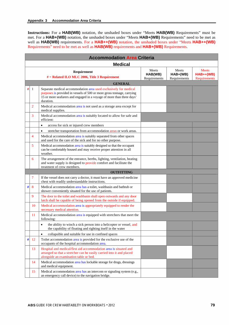
Appendix 3 Accommodation Area Criteria
ABS GUIDE FOR CREW HABITABILITY ON WORKBOATS . 2012 79
Instructions: For a HAB(WB) notation, the unshaded boxes under “Meets HAB(WB) Requirements” must be met. For a HAB+(WB) notation, the unshaded boxes under “Meets HAB+(WB) Requirements” need to be met as well as HAB(WB) requirements. For a HAB++(WB) notation, the unshaded boxes under “Meets HAB++(WB) Requirements” need to be met as well as HAB(WB) requirements and HAB+(WB) Requirements.
Accommodation Area Criteria Medical
Requirement # = Related ILO MLC 2006, Title 3 Requirement
Meets HAB(WB)
Requirements
Meets HAB+(WB) Requirements
Meets HAB++(WB) Requirements
GENERAL # 1 Separate medical accommodation area used exclusively for medical
purposes is provided in vessels of 500 or more gross tonnage, carrying 15 or more seafarers and engaged in a voyage of more than three days’ duration.
2 Medical accommodation area is not used as a storage area except for medical supplies.
3 Medical accommodation area is suitably located to allow for safe and efficient:
• access for sick or injured crew members • stretcher transportation from accommodation areas or work areas. 4 Medical accommodation area is suitably separated from other spaces
and used for the care of the sick and for no other purpose.
5 Medical accommodation area is suitably designed so that the occupant can be comfortably housed and may receive proper attention in all weather.
6 The arrangement of the entrance, berths, lighting, ventilation, heating and water supply is designed to provide comfort and facilitate the treatment of crew members.
OUTFITTING 7 If the vessel does not carry a doctor, it must have an approved medicine
chest with readily understandable instructions.
# 8 Medical accommodation area has a toilet, washbasin and bathtub or shower conveniently situated for the use of patients.
9 The door to the toilet and washbasin shall open outwards and any door latch shall be capable of being opened from the outside if equipped.
10 Medical accommodation area is appropriately equipped to render the necessary medical attention.
11 Medical accommodation area is equipped with stretchers that meet the following:
• the ability to winch a sick person into a helicopter or vessel, and the capability of floating and righting itself in the water
• collapsible and suitable for use in confined spaces # 12 Toilet accommodation area is provided for the exclusive use of the
occupants of the hospital accommodation area.
13 Hospital and medical/first aid accommodation area is situated and arranged so that a stretcher can be easily carried into it and placed alongside an examination table or bed.
14 Medical accommodation area has lockable storage for drugs, dressings and medical equipment.
15 Medical accommodation area has an intercom or signaling system (e.g., an emergency call device) to the navigation bridge.
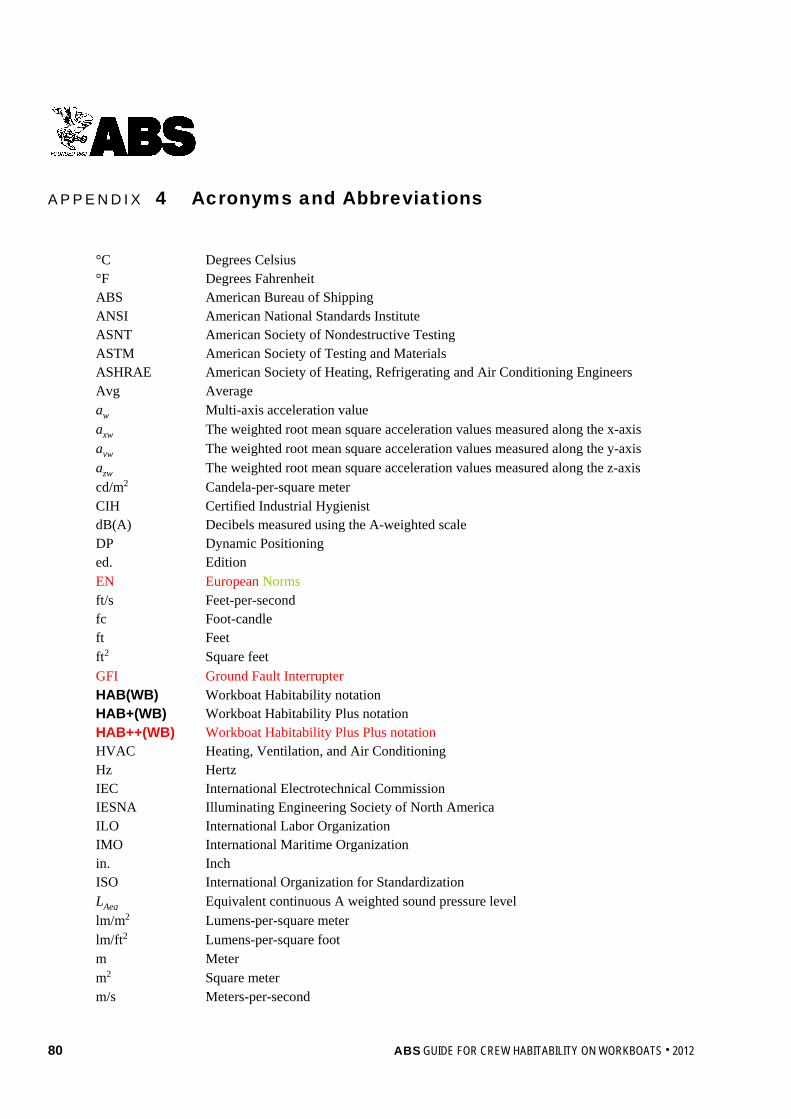
80 ABS GUIDE FOR CREW HABITABILITY ON WORKBOATS . 2012
A p p e n d i x 4 : A c r o n y m s a n d A b b r e v i a t i o n s
A P P E N D I X 4 Acronyms and Abbreviations
°C Degrees Celsius °F Degrees Fahrenheit ABS American Bureau of Shipping ANSI American National Standards Institute ASNT American Society of Nondestructive Testing ASTM American Society of Testing and Materials ASHRAE American Society of Heating, Refrigerating and Air Conditioning Engineers Avg Average aw Multi-axis acceleration value axw The weighted root mean square acceleration values measured along the x-axis ayw The weighted root mean square acceleration values measured along the y-axis azw The weighted root mean square acceleration values measured along the z-axis cd/m2 Candela-per-square meter CIH Certified Industrial Hygienist dB(A) Decibels measured using the A-weighted scale DP Dynamic Positioning ed. Edition EN European Norms ft/s Feet-per-second fc Foot-candle ft Feet ft2 Square feet GFI Ground Fault Interrupter HAB(WB) Workboat Habitability notation HAB+(WB) Workboat Habitability Plus notation HAB++(WB) Workboat Habitability Plus Plus notation HVAC Heating, Ventilation, and Air Conditioning Hz Hertz IEC International Electrotechnical Commission IESNA Illuminating Engineering Society of North America ILO International Labor Organization IMO International Maritime Organization in. Inch ISO International Organization for Standardization LAeq Equivalent continuous A weighted sound pressure level lm/m2 Lumens-per-square meter lm/ft2 Lumens-per-square foot m Meter m2 Square meter m/s Meters-per-second
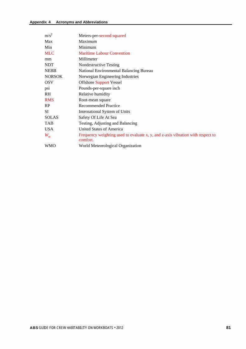
Appendix 4 Acronyms and Abbreviations
ABS GUIDE FOR CREW HABITABILITY ON WORKBOATS . 2012 81
m/s2 Meters-per-second squared Max Maximum Min Minimum MLC Maritime Labour Convention mm Millimeter NDT Nondestructive Testing NEBB National Environmental Balancing Bureau NORSOK Norwegian Engineering Industries OSV Offshore Support Vessel psi Pounds-per-square inch RH Relative humidity RMS Root-mean square RP Recommended Practice SI International System of Units SOLAS Safety Of Life At Sea TAB Testing, Adjusting and Balancing USA United States of America Wm Frequency weighting used to evaluate x, y, and z-axis vibration with respect to
comfort. WMO World Meteorological Organization
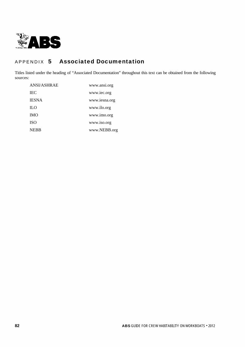
82 ABS GUIDE FOR CREW HABITABILITY ON WORKBOATS . 2012
A p p e n d i x 5 : A s s o c i a t e d D o c u m e n t a t i o n
A P P E N D I X 5 Associated Documentation
Titles listed under the heading of “Associated Documentation” throughout this text can be obtained from the following sources:
ANSI/ASHRAE www.ansi.org
IEC www.iec.org
IESNA www.iesna.org
ILO www.ilo.org
IMO www.imo.org
ISO www.iso.org
NEBB www.NEBB.org