Embed Size (px)
Citation preview

August 2018
Guidance Notefor the Classification, Safe Design,Construction and Operation of Tugs
1
Contents
Chapter 1 – Background information ........................................................................................................................... 2 Section 1 - Introduction ................................................................................................................................................ 2
1.1 Background ................................................................................................................................................... 2 1.2 Scope ............................................................................................................................................................ 2 1.3 Definitions ..................................................................................................................................................... 3 1.4 General Guidance ......................................................................................................................................... 5 1.5 Escorting dynamics ....................................................................................................................................... 6
Section 2 - Operations and arrangements .................................................................................................................... 7 2.1 Typical tug operational profiles ................................................................................................................... 7 2.2 Typical tug arrangements ............................................................................................................................. 7
Chapter 2 – Classification ............................................................................................................................................. 9 Section 1 - Notations .................................................................................................................................................... 9
1.1 Type and Service Restriction Notations ........................................................................................................ 9 Section 2 - Classification Guidance ............................................................................................................................. 11
2.1 Hull .............................................................................................................................................................. 11 2.2 Towing arrangements for Tugs ................................................................................................................... 12 2.3 Towing arrangements for Escort Tugs ........................................................................................................ 21 2.4 Fendering .................................................................................................................................................... 27 2.5 Escort operation performance numeral and trials ..................................................................................... 28 2.6 Anchoring Equipment ................................................................................................................................. 28 2.7 Machinery and Electrotechnical systems ................................................................................................... 30 2.8 Fire protection, detection and extinction ................................................................................................... 30
Chapter 3 – Statutory ................................................................................................................................................. 31 Section 1 - Scope......................................................................................................................................................... 31
1.1 Statute and this Guidance note .................................................................................................................. 31 Section 2 - Stability ..................................................................................................................................................... 32
2.1 Scope of application ................................................................................................................................... 32 2.2 Openings ..................................................................................................................................................... 32 2.3 Intact stability ............................................................................................................................................. 33
Section 3 - Safety Equipment ..................................................................................................................................... 41 3.1 Fire safety for tugs of less than 500 GT ...................................................................................................... 41 3.2 Life-saving appliances for tugs of less than 500 GT .................................................................................... 52 3.3 Radio installation for tugs of less than 300 GT ........................................................................................... 53
Lloyd’s Register and variants of it are trading names of Lloyd’s Register Group Limited, its subsidiaries and affiliates. For further details please see http://www.lr.org/entities Lloyd's Register Group Limited, its subsidiaries and affiliates and their respective officers, employees or agents are, individually and collectively, referred to in this clause as ‘Lloyd's Register’. Lloyd's Register assumes no responsibility and shall not be liable to any person for any loss, damage or expense caused by reliance on the information or advice in this document or howsoever provided, unless that person has signed a contract with the relevant Lloyd's Register entity for the provision of this information or advice and in that case any responsibility or liability is exclusively on the terms and conditions set out in that contract.
2
Chapter 1 – Background information
Section 1- Introduction
1.1 Background 1.1.1 This guidance note has been produced to provide guidance on the Classification of tugs with Lloyd’s Register, including information on tug types, operational restrictions, notations and design calculations. In addition, for tugs with a (freeboard) length LLL ( as defined in the International Convention on Load Lines (ICLL)) of not more than 100 m, this note goes beyond the limited scope of Class Rules to provide guidance on best practice and general statutory requirements.
1.2 Scope 1.2.1 The content of this guidance note relating to Classification aspects is relevant to all tugs eligible for Classification to which one or more of the Type Notations specified in Ch 2, 1.1 Type and Service Restriction Notations intended to be are assigned. 1.2.2 The content of this guidance note relating to statutory aspects is relevant to tugs having a (freeboard) length LLL, as defined in the International Convention on Load Lines (ICLL), of not more than 100 m. 1.2.3 Classification of tugs requires that the vessel complies with the Rules and Regulations of Lloyds Register. The relevant requirements are made up of the general requirements for all vessels in the Rue and Regulations for the Classification of Ships (The Ship Rules) and any relevant specific requirements. For all tugs the Classification requirements may include;
• Pt 1, Ch 2, 2 Character of classification and class notations, 2.1.6 • Pt 1, Ch2, 3 Surveys – General, 3.2.6 • Pt 3, Ch 1, 7 Equipment Number, 7.1.5 • Pt 3, Ch 8, 5.5 Special requirements for tugs and offshore supply ships • Pt 3, Ch 13, 7 Equipment • Pt 4, Ch 3 Tugs
The above list of applicable requirements is not exhaustive and may vary from vessel to vessel based on the operational profile, the tug type, equipment, fit out etc. 1.2.4 All vessels are subject to the requirements set out by their relevant Flag Administration(s). Typically, such statutory requirements go beyond the scope of class. This Guidance note sets out some general guidelines in these areas however in all cases the requirements of the relevant flag Administration(s) are to be applied. 1.2.5 There should be no instances where this guidance conflicts with the requirements of the Flag Administration, however if an instance is identified for a vessel that is to be Classed the conflict should be highlighted to Lloyd’s Register at the earliest opportunity to ensure that the conflict is rectified as soon as possible to allow Classing and Flagging of the vessel. 1.2.6 The Rules and these guidance notes assume that no escort operations will be conducted at speeds greater than 10 kn, however for vessels designed to conduct escort at speeds greater than this application of the Rules and these guidance will be specially considered.
1.2.7 The sizing of the prime mover and the propulsion chain to develop sufficient thrust for the vessel to perform her predicted duties is beyond the scope of Classification.

3
1.3 Definitions 1.3.1 Design bollard pull The design bollard pull TBP, in kN, is the maximum sustained towline force a tug is capable of generating at zero forward speed, to be initially specified by the designer and to be verified by a full scale test, generally referred to as bollard pull test.
Where TBP is not available, the following default values may be used as an estimate for a preliminary design review:
- TBP = 0,204NPS for conventional tugs with propellers fitted with nozzles; - TBP = 0,176NPS for tractor tugs and ASD tugs with steerable propellers fitted with nozzles.
where: N : number of propellers; PS : maximum continuous power per propeller shaft, in kW.
1.3.2 Escort forces and speed The steady towline force during escorting, Ft in kN, is the towline force associated with the (quasi-static) equilibrium in indirect towing mode, excluding short time-duration dynamic effects, for a given loading condition and escort speed V, see Figure 1.3.1 Typical escort configuration. The steady towline force is applied by the tug on the stern of the escorted ship.
Figure 1.3.1: Typical escort configuration

4
Additionally, the steady towline force Ft can be decomposed into a steering force Fs and a braking force Fb :
- The steering force Fs, in kN, is the transverse component of the steady towline force Ft with respect to the escorted ship;
- The braking force Fb, in kN, is the longitudinal component of the steady towline force Ft with respect to the escorted ship.
For the purpose of this guidance note the following rated values of the above defined escort forces are defined as:
- The rated steady towline force Ft,R, in kN, is the highest anticipated steady towline force Ft, as obtained from the evaluation of the escort forces for a particular loading condition and escort speed, taking into account the applicable stability and strength criteria in this guidance note;
- The rated steering force Fs,R, in kN, is the highest anticipated steering force Fs, as obtained from the evaluation of the escort forces for a particular loading condition and escort speed, taking into account the applicable stability and strength criteria in this guidance note;
- The rated maximum braking force Fb,R, in kN, is the highest anticipated braking force Fb, as obtained from the evaluation of the escort forces for a particular loading condition and escort speed, taking into account the applicable stability and strength criteria in this guidance note.
And the associated maximums are,
- The design maximum steady towline force Ft,MAX, in kN, is the highest rated steady towline force Ft,R over the
applicable range of loading conditions and escort speeds; - The design maximum steering force Fs,MAX, in kN, is the highest rated steering force Fs,R over the applicable range
of loading conditions and escort speeds; - The design maximum braking force Fb,MAX, in kN, is the highest rated braking force Fb,R over the applicable range
of loading conditions and escort speeds. - The maximum escort speed VMAX, in kn, is the highest escort speed V for which the escort tug is considered to
perform escort operations. For the purpose of this guidance note the following relevant angles are defined as:
- The towline angle α, in deg, is the angle between the towline and the centreline of the escorted ship and; - The drift angle β, in deg, is the angle between the centreline of the tug and the centreline of the escorted ship
(also referred to as yaw angle). 1.3.3 Reference towline force The reference (quasi-static) towline force T, in kN, is considered to represent:
- the design bollard pull TBP for type notations tug, see Ch 1, 1.3 Definitions 1.3.1; - the maximum steady towline force Ft,MAX for type notation escort tug, see Ch 1, 1.3 Definitions 1.3.2.
1.3.4 Design load The design load (DL), in kN, is the force taken into consideration for the strength assessment and testing of the towing equipment and the associated supporting structures, and for the purposes of design appraisal it is taken as not less than:
DL = DAFT
where DAF: dynamic amplification factor
The dynamic amplification factor takes into consideration dynamic effects. Reference values for the dynamic amplification factor are given in:
• For type notation tug: Ch 2, 2.2 Towing arrangements for Tugs 2.2.3 • For type notation escort tug: Ch 2, 2.3 Towing arrangements for Escort Tugs 2.3.5.

5
1.3.5 Winch brake holding load The winch brake holding load (BHL), in kN, is the maximum towline force the towing winch can withstand without slipping of the (activated) brake, considering the towline at the first inner layer.
The BHL is a reference value for strength assessment and testing of towing winches and associated towing fittings (e.g. fairlead, staple, gob-eye) as well as their supporting structures.
1.3.6 Towline breaking strength The towline breaking strength, in kN, is the tension required to cause failure of the towline (parting of the towline).
1.4 General Guidance 1.4.1 All bollard pull tests should be performed in accordance with a recognised Standard, such as the ‘Lloyd’s Register Bollard Pull certification procedures guidance information’, and witnessed by a Lloyd’s Register Surveyor.
1.4.2 For tugs capable of towing over the stern (ahead towing) as well as over the bow (astern towing), the bollard pull test should be performed for both scenarios.
1.4.3 If the measured bollard pull for any vessel is higher than the design bollard pull (TBP) by 1 per cent or more then aspects of the design appraisal of the vessel may need to be redone reflecting this new bollard pull. The extent of reappraisal is at the discretion of Lloyds Register.
1.4.4 Angles α and β and maximum escort speed VMAX (see Figure 1.3.1 Typical escort configuration) should be defined by the designer prior to commencement of design appraisal. 1.4.5 The matrix of rated steady towline forces Ft,R, steering forces Fs,R and braking forces Fb,R should be specified by the designer for design appraisal and are latterly verified by Lloyd’s Register on the basis of the results of:
full scale trials, or model testing, or a computer simulation program accepted by Lloyd’s Register.
1.4.6 All full scale trials conducted to verify the above matrix of forces, should be performed in accordance with a procedure agreed with Lloyd’s Register prior to commencement of the trials. Further guidance on such trials is contained in Ch 3, 2.3 Intact stability 2.3.6.
1.4.7 All Model testing, where applicable, should be performed in accordance with a procedure agreed with Lloyd’s Register before commencement of the tests. The testing should comply with the relevant aspects of Ch 3, 2.3 Intact stability 2.3.6.
1.4.8 Special attention should be paid to scale effects when processing any model scale measurement results to create predictions at full scale.
1.4.9 Computer simulation programs for predicting escort performance should comply with the relevant aspects of Ch 3, 2.3 Intact stability 2.3.5.
1.4.10 Lloyd’s Register will accept escort performance predictions from computer simulation programs in lieu of full scale trials where the predictions are carried out in accordance with Lloyd’s Register’s ShipRight Procedure titled Guidelines for CFD Escort Tug Performance as detailed in Pt 4, Ch 3, 9.4 Computational Fluid Dynamics Predicted Performance of the Ship Rules
1.4.11 In order to maintain the Classification of any tug, the vessel will be subject to an ongoing periodical survey regime to ensure that the vessel and the equipment relevant for Classification remain in a worthy condition. Details of the through life survey requirements can be found in Part 1 of the Ship Rules.
1.4.12 For high powered escort tugs (with a free running speed of more than 15 kn) Lloyd’s Register will specially consider the application of the Rules and these Guidance notes to the vessel assuming an escort speed of 12 kn.
1.4.13 Propulsion engines and propulsion train should develop sufficient thrust for manoeuvring the tug quickly for any drift angle, and in the case of loss of propulsion, the heeling moment due to the remaining forces should lead to a safe equilibrium position of the tug with reduced heeling angle.

6
1.5 Escorting dynamics 1.5.1 For the purpose of this guidance note, escorting is considered to include active (emergency) steering, braking and otherwise controlling of the escorted ship by the tug operating in indirect towing mode, whereby the ahead speed of the escorted ship is within a typical speed range of 6 to 10 kn. 1.5.2 In indirect towing mode the towline force is the resultant of the (quasi-static) equilibrium condition reached between the forces and moments arising from the hydrodynamic lift and drag forces acting on the hull and appendices of the tug advancing through the water at a drift angle relative to the water flow, the thrust vector and the towline force (In direct towing mode the thrust is directly applied to generate the towline force, hydrodynamic lift and drag forces play no significant role).
Escort tugs may work in different indirect towing modes, depending on the required action towards the escorted ship (e.g. steering, braking). The main indirect towing modes relevant for escort tugs are schematically shown in Figure 1.5.1 Schematic overview of indirect towing modes (escort tug). Where reference is made to ‘indirect steering’ the objective is to maximise the steering force in indirect towing mode. Where reference is made to ‘indirect braking’ the objective is to maximise the braking force in indirect towing mode. In (basic) indirect mode the towline force is generated primarily by the hydrodynamic forces acting on the hull and skeg, with the thrust used solely to maintain the desired drift angle (also referred to as yaw angle). In powered indirect mode (indirect steering) the transverse component of thrust is used to maintain the desired drift angle, while a significant longitudinal component of thrust is applied in forward direction of the tug. Compared to the (basic) indirect mode, the tug is operating more sideways of the escorted ship with a relatively large towline angle, generating a higher steering force. In combination mode (indirect braking) the same principle as for the indirect steering mode is applied, except that the longitudinal component of thrust is applied in aftward rather than forward direction. Compared to the (basic) indirect mode, the tug is operating more behind the escorted ship with a relatively small towline angle, generating a higher braking force. For indirect towing modes it is generally recognised that it is beneficial to design the tug to generate high (indirect) towline forces with minimal propulsion thrust, while respecting the limits imposed by stability and strength considerations (towing equipment, general hull structure).
Figure 1.5.1 Schematic overview of indirect towing modes (escort tug)
7
Section 2- Operations and arrangements
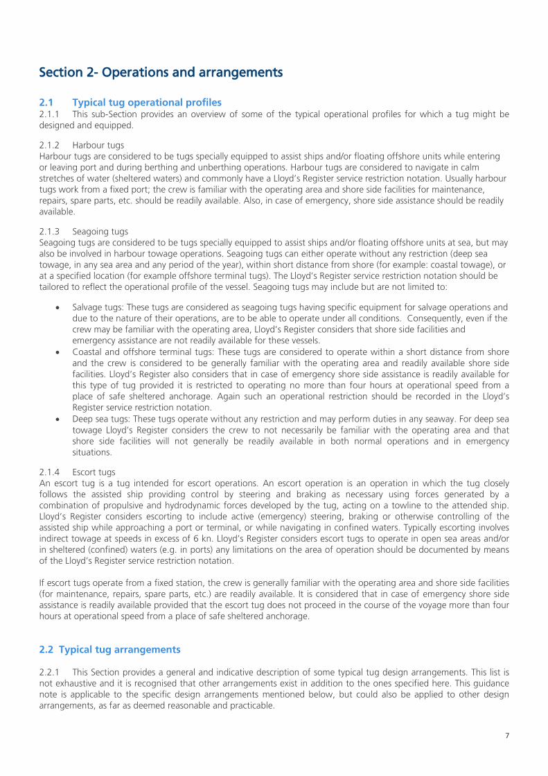
2.1 Typical tug operational profiles 2.1.1 This sub-Section provides an overview of some of the typical operational profiles for which a tug might be designed and equipped.
2.1.2 Harbour tugs Harbour tugs are considered to be tugs specially equipped to assist ships and/or floating offshore units while entering or leaving port and during berthing and unberthing operations. Harbour tugs are considered to navigate in calm stretches of water (sheltered waters) and commonly have a Lloyd’s Register service restriction notation. Usually harbour tugs work from a fixed port; the crew is familiar with the operating area and shore side facilities for maintenance, repairs, spare parts, etc. should be readily available. Also, in case of emergency, shore side assistance should be readily available.
2.1.3 Seagoing tugs Seagoing tugs are considered to be tugs specially equipped to assist ships and/or floating offshore units at sea, but may also be involved in harbour towage operations. Seagoing tugs can either operate without any restriction (deep sea towage, in any sea area and any period of the year), within short distance from shore (for example: coastal towage), or at a specified location (for example offshore terminal tugs). The Lloyd’s Register service restriction notation should be tailored to reflect the operational profile of the vessel. Seagoing tugs may include but are not limited to:
• Salvage tugs: These tugs are considered as seagoing tugs having specific equipment for salvage operations and due to the nature of their operations, are to be able to operate under all conditions. Consequently, even if the crew may be familiar with the operating area, Lloyd’s Register considers that shore side facilities and emergency assistance are not readily available for these vessels.
• Coastal and offshore terminal tugs: These tugs are considered to operate within a short distance from shore and the crew is considered to be generally familiar with the operating area and readily available shore side facilities. Lloyd’s Register also considers that in case of emergency shore side assistance is readily available for this type of tug provided it is restricted to operating no more than four hours at operational speed from a place of safe sheltered anchorage. Again such an operational restriction should be recorded in the Lloyd’s Register service restriction notation.
• Deep sea tugs: These tugs operate without any restriction and may perform duties in any seaway. For deep sea towage Lloyd’s Register considers the crew to not necessarily be familiar with the operating area and that shore side facilities will not generally be readily available in both normal operations and in emergency situations.
2.1.4 Escort tugs An escort tug is a tug intended for escort operations. An escort operation is an operation in which the tug closely follows the assisted ship providing control by steering and braking as necessary using forces generated by a combination of propulsive and hydrodynamic forces developed by the tug, acting on a towline to the attended ship. Lloyd’s Register considers escorting to include active (emergency) steering, braking or otherwise controlling of the assisted ship while approaching a port or terminal, or while navigating in confined waters. Typically escorting involves indirect towage at speeds in excess of 6 kn. Lloyd’s Register considers escort tugs to operate in open sea areas and/or in sheltered (confined) waters (e.g. in ports) any limitations on the area of operation should be documented by means of the Lloyd’s Register service restriction notation. If escort tugs operate from a fixed station, the crew is generally familiar with the operating area and shore side facilities (for maintenance, repairs, spare parts, etc.) are readily available. It is considered that in case of emergency shore side assistance is readily available provided that the escort tug does not proceed in the course of the voyage more than four hours at operational speed from a place of safe sheltered anchorage.
2.2 Typical tug arrangements 2.2.1 This Section provides a general and indicative description of some typical tug design arrangements. This list is not exhaustive and it is recognised that other arrangements exist in addition to the ones specified here. This guidance note is applicable to the specific design arrangements mentioned below, but could also be applied to other design arrangements, as far as deemed reasonable and practicable.
8
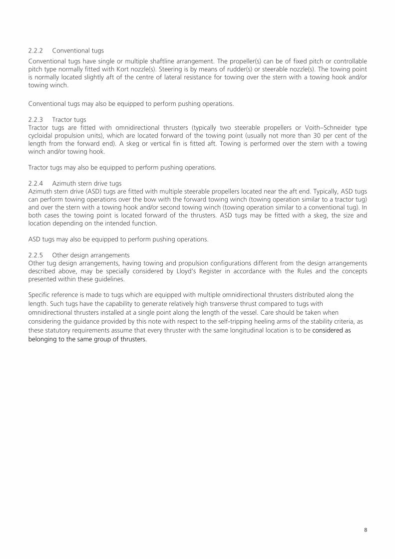
2.2.2 Conventional tugs
Conventional tugs have single or multiple shaftline arrangement. The propeller(s) can be of fixed pitch or controllable pitch type normally fitted with Kort nozzle(s). Steering is by means of rudder(s) or steerable nozzle(s). The towing point is normally located slightly aft of the centre of lateral resistance for towing over the stern with a towing hook and/or towing winch.
Conventional tugs may also be equipped to perform pushing operations. 2.2.3 Tractor tugs Tractor tugs are fitted with omnidirectional thrusters (typically two steerable propellers or Voith–Schneider type cycloidal propulsion units), which are located forward of the towing point (usually not more than 30 per cent of the length from the forward end). A skeg or vertical fin is fitted aft. Towing is performed over the stern with a towing winch and/or towing hook. Tractor tugs may also be equipped to perform pushing operations. 2.2.4 Azimuth stern drive tugs Azimuth stern drive (ASD) tugs are fitted with multiple steerable propellers located near the aft end. Typically, ASD tugs can perform towing operations over the bow with the forward towing winch (towing operation similar to a tractor tug) and over the stern with a towing hook and/or second towing winch (towing operation similar to a conventional tug). In both cases the towing point is located forward of the thrusters. ASD tugs may be fitted with a skeg, the size and location depending on the intended function. ASD tugs may also be equipped to perform pushing operations. 2.2.5 Other design arrangements Other tug design arrangements, having towing and propulsion configurations different from the design arrangements described above, may be specially considered by Lloyd’s Register in accordance with the Rules and the concepts presented within these guidelines. Specific reference is made to tugs which are equipped with multiple omnidirectional thrusters distributed along the length. Such tugs have the capability to generate relatively high transverse thrust compared to tugs with omnidirectional thrusters installed at a single point along the length of the vessel. Care should be taken when considering the guidance provided by this note with respect to the self-tripping heeling arms of the stability criteria, as these statutory requirements assume that every thruster with the same longitudinal location is to be considered as belonging to the same group of thrusters.

9
Chapter 2 – Classification
Section 1 – Notations
1.1 Type and Service Restriction Notations 1.1.1 As with all vessels that are to enter into Class, the governing requirements for the tugs are partially dictated by the notations that are to be associated with the vessel. Notations may describe the type of vessel, its operational profiles, functions and fit out. From a Classification perspective, this guidance note focuses on the Type Notations and the Service Restriction Notations for tugs. Full listings of these can be found in Pt 1, Ch 2, 2 Character of classification and class notations, 2.1.6 and Pt 1, Ch 2, 2 Character of classification and class notations, 2.1.11 of the Ship Rules respectively. 1.1.2 Lloyd’s Register offers a number of different Type Notations for tugs which may follow the typical arrangements listed previously, these are:
• Tug • AHTS (Anchor Handler Tug Supply) • Offshore tug • Escort tug
For Classification, a vessel assigned any of the above Type Notations should comply with the requirements listed in Pt 4, Ch 3 Tugs and Pt 3, Ch 8, 5.5 Special requirements for tugs and offshore supply ships of the Ship Rules, the general design and construction requirements of the Ship Rules, the general Rule requirements for the propulsion and engineering systems of the Ship Rules as well as all Statutory/Flag Administration requirements as applicable.
1.1.3 Additional design requirements for Classification are dependent on the Type notation:
• AHTS are considered to be sea-going vessels specially designed and constructed to support the operations of offshore installations, including the carriage of specialised stores and cargoes to such facilities. This notation is assigned to vessels designed for anchor handling, towing and supply of specialised stores and cargo to offshore installations.
Vessels with this notation are additionally required to comply with Pt 4, Ch 4, 1 General to Pt 4, Ch 4, 8 Transport and handling of limited amounts of hazardous and noxious liquid substances in bulk of the Ship Rules.
Vessels with this notation are a subset of the Type Notation Tug, as such the requirements in the Rules and the guidance within this note applicable to tugs, unless specifically excluded, are also applicable to vessels with the AHTS Notation.
• Offshore Tugs are considered to be sea-going vessels specially designed and constructed to support the operations of offshore installations through tug operations.
Vessels with this notation are additionally required to comply with Pt 4, Ch 4, 1 General to Pt 4, Ch 4, 8 Transport and handling of limited amounts of hazardous and noxious liquid substances in bulk of the Ship Rules.
Vessels with this notation are a subset of the Type Notation Tug, as such the requirements in the Rules and the guidance within this note applicable to tugs, unless specifically excluded, are also applicable to vessels with the Offshore Tug Notation.
• Escort Tugs are those tugs which are designed be used in escort operations as detailed in Ch 1, 1.2 Typical tug operational profiles 2.1.4
Vessels with this notation are additionally required to comply with Pt 4, Ch 3, 9 Escort operation, performance numeral and trials of the Ship Rules.
Additional reference is made to Pt 1, Ch 2, 2 Character of classification and class notations, 2.3.21 to Pt 1, Ch 2, 2 Character of classification and class notations, 2.3.23 of the Ship Rules

10
1.1.4 Service Restriction Notations indicate that a ship has been classed conditional to operation only in specific areas which have been agreed by the Classification Committee. If a vessel has no Service Restriction Notation, at design appraisal it is considered to be an unrestricted seagoing vessel according to the 100 character notation. In the case of many tugs e.g. Harbour tugs, designing to unrestricted seagoing service may be too onerous, therefore a ‘Service Restriction Notation’ can be used to reflect a more appropriate operational profile of the vessel. Typical Service Restriction Notations for tugs might be one of the following:
Type of Service Restriction Notations
Typical Text for Service Restriction Notations
Tug specific explanation
Protected waters service Protected waters service at “geographical location”
For vessels limited to conducting operations in non-exposed waters, where the environmental impact on the service is negligible. In general, sheltered water may be considered as waters adjacent to sand banks, reefs, breakwaters or other coastal features, and in sheltered water between islands.
Specified route service For service at the Port of “name of port”
For vessels operating within a specific port and within the defined navigational boundaries of that port.
Specified Coastal Service “Country- Specific” Coastal Service
For vessels operating within specified maritime coastal waters in accordance with the requirements of the relevant National Administration and/or at a defined distance offshore where it may seek refuge within two hours of sailing at normal service speed.
Specified operating area service
For service within “X”nm “name of geographical point”
Or
For service within “defined geographical area”
For vessels operating within a specified area.
Note that this is not an exhaustive list of Service restriction notations and others may be available or agreed by the classification committee. Further information on Service Restriction Notations can be found in Pt 1, Ch 2, 2 Character of classification and class notations, 2.3.1, 2.3.4 and, 2.3.6 to 2.3.10 of the Ship Rules. This guidance note makes use of ‘Protected waters service’ Service restriction notation and restriction notations which limit the operational range to refuge of the vessel to within 5 nm or 4 hours at standard operational speed. For example ‘For service within 5 nm of Shoreham Port’ or ‘For service within 48 nm of Eemshaven’ (the second notation represents 4 hours traveling at operational speed of 12 kts)
11
Section 2 – Classification Guidance
2.1 Hull 2.1.1 The Hull design and construction requirements for tugs are all contained within the Ship Rules and both vessels with the Type notation Tug or Escort Tug are to comply with the Rules and regulations of this Ruleset to be eligible for classification with Lloyds Register. In addition to the Ship structures (general) requirements for all vessels of the Ship Rules (all contained within Pt 3), there are is also a specific ship structures section of the Rules dedicated to tug structures. This section is Pt 4, Ch 3 Tugs and it contains the following sections: Section 1 General Section 2 Longitudinal strength Section 3 Floors in Single bottoms Section 4 Panting and strengthening of bottom forward Section 5 Machinery casings Section 6 Freeing arrangements Section 7 Towing arrangements Section 8 Fenders Section 9 Escort operation, performance numeral and trials The content of each of these sections is generally self-explanatory with content referring out to other sections of the Ship Rules to be complied with and/or listing additional requirements or exceptions. Of particular interest in the above is Sections 7 and 8 (additionally section 9 for Escort Tugs), these are discussed in the following sub-Sections.

12
2.2 Towing arrangements for Tugs 2.2.1 The Rule requirements relating to the towing equipment and their foundations are contained within Pt 4, Ch3 Section 7 of The Ship Rules. In addition, materials used in towing equipment should comply with the applicable class requirements for materials. Class certificates are generally required for the materials used for winch drums, drum shafts, winch brake components, winch supporting frames, towing hooks and towline guiding fittings installed upon classed vessels.
2.2.2 Documents to be submitted
In order for the plan appraisal of the towing equipment and the associated foundations to be undertaken, the following documents should be submitted for appraisal (assuming no Type Approval is in place): - Drawings of towing winches, including winch drums, main shaft, load carrying non-rotating structures (support
frame), winch brakes. Gear and clutch information is also to be submitted for information; - Hydraulic, electrical and control system diagrams of the towing winch, as applicable (note that this may be used
for information as required); - Drawings of towing hook and towline guiding fittings; - Drawings of foundations and under deck supporting structures (clearly showing reinforcements) of towing
equipment including scantlings and attachment methods as appropriate.
In addition to the above and to further facilitate the plan appraisal the follow may be supplied to Lloyd’s Register for
information:
- Towing arrangement plan, showing the location and general layout of the towing equipment, the range of anticipated lines of action of the towlines with the associated maximum steady towline forces (also known as the quasi-static towline force) and the corresponding points of application of the towline forces on the towing equipment;
- Arrangement drawings of towing winches, towing hooks and towline guiding fittings (fairleads, staples, gob-eyes, towing pins, stern roller, etc.);
- Design information of towing winches, including maximum rated line pull, winch brake holding force, rendering load and specification of emergency quick-release arrangements;
- Design calculations of towing winches, including winch drums, main shaft, load carrying non-rotating structures (support frame) and braking capacity;
- Design load of towing hook and towline guiding fittings; - Design calculations of the towline guiding fittings and the supporting structures of towing equipment, including
detailed analysis reports in case three-dimensional finite element models have been used.
Additionally, where deemed necessary by Lloyd’s Register, buckling and/or fatigue analysis, performed in accordance with a standard or code of practice recognised by Lloyd’s Register, may be required to be submitted for information.

13
2.2.3 Consideration of the design load One of the critical factors in the design appraisal of the towing equipment and its foundation is the design load (DL) that should be considered for the strength assessment of the towing equipment and the associated supporting structures. This is outlined in the Rules and also given in Table 2.2.1 Design loads: tug of this guidance for easy reference.
Table 2.2.1 Design loads: tug
The DL (in the Rules and in the table) take into consideration the assumed dynamic effects through the application of the dynamic amplification factor (DAF) which is clearly designated in square brackets in Table 2.2.1 Design loads: tug (see also Ch 1, 1.3 Definitions 1.3.4).
2.2.4 Design requirements for towing winches The Rules require that the scantlings for towing winches (including winch drums, drum shafts, brakes, support frames and connections to the hull structure) are to be determined by direct calculations using the Design Loads (outlined in Table 2.2.1 Design loads: tug)
The calculations should demonstrate that the towing winches (in particular the components which are exposed to the tension in the towline, such as the winch drums, drum shafts, brakes, support frame and connection to the hull structure) are able to: - sustain the DL, without permanent deformation, and; - sustain the BHL, (as defined in Ch 1, 1.3 Definitions 1.3.5), without exceeding an equivalent stress level (based on
von Mises criterion) of 0,80σy; - sustain the loads for the RP condition, as foreseen by the designer, without exceeding an equivalent stress level
(based on the von Mises criterion) of 0,40σy. where
σy: Minimum specified yield stress of material, in N/mm2; RP: Is the Rated Pull i.e. the winch maximum hauling in load at the first inner layer.
In each calculation case the most unfavourable anticipated position of the towline should be considered.
tug with service restriction notation protected waters e.g. a harbour tug
General case
Bollard pull, TBP [kN]
Design load, DL [kN]
Bollard pull, TBP [kN]
Design load, DL [kN]
T ≤ 200 [2]T T ≤ 400 [2,5]T
200 < T < 800 [(2600 − T)/1200]T 400 < T < 1000 [(3400 − T)/1200)]T
T ≥ 800 [1,5]T T ≥ 1000 [2]T
14
2.2.5 Additional design guidance for towing winches
In addition to the Rule requirements outlined in Ch2, 2.2 Towing arrangements for Tugs 2.2.4, the following design guidelines should be followed.
Towing winches should generally be arranged in such a position (noting the position of guiding fittings and towline path) as to minimise heeling moment due to the towline force.
The winch brake should normally act directly on the drum and should be operable (either manually or otherwise) in case of failure of the primary power supply system.
The towline attachment to the winch drum should be provided by means of a weak link or equivalent.
Towing winches should be provided with an emergency release system as described in Ch 2, 2.2 Towing arrangements for Tugs 2.2.10.
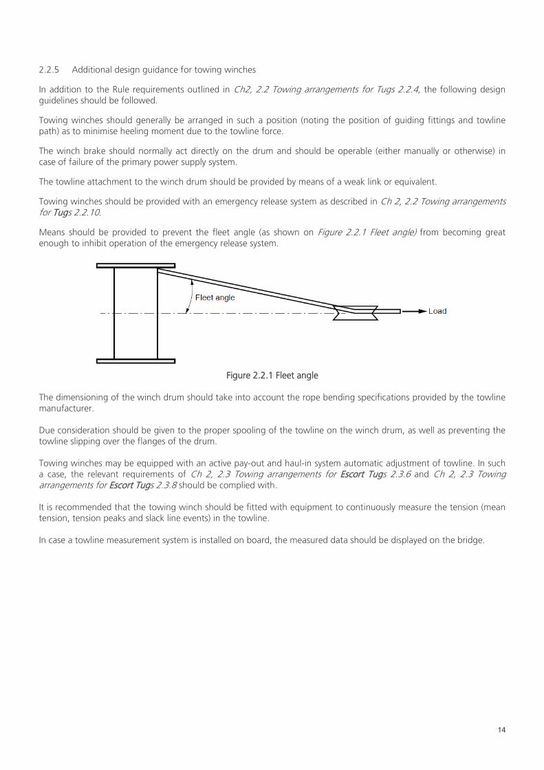
Means should be provided to prevent the fleet angle (as shown on Figure 2.2.1 Fleet angle) from becoming great enough to inhibit operation of the emergency release system.
Figure 2.2.1 Fleet angle
The dimensioning of the winch drum should take into account the rope bending specifications provided by the towline manufacturer. Due consideration should be given to the proper spooling of the towline on the winch drum, as well as preventing the towline slipping over the flanges of the drum. Towing winches may be equipped with an active pay-out and haul-in system automatic adjustment of towline. In such a case, the relevant requirements of Ch 2, 2.3 Towing arrangements for Escort Tugs 2.3.6 and Ch 2, 2.3 Towing arrangements for Escort Tugs 2.3.8 should be complied with. It is recommended that the towing winch should be fitted with equipment to continuously measure the tension (mean tension, tension peaks and slack line events) in the towline. In case a towline measurement system is installed on board, the measured data should be displayed on the bridge.
15
2.2.6 Guidelines on testing of towing winches The following guidelines outline the appropriate testing regimes for towing winches installed on board tugs.
Towing winches, including the associated emergency quick-release devices should be load tested at the DL, as defined in Ch 2, 2.2 Towing arrangements for Tugs 2.2.3, or the BHL, as defined in Ch 1, 1.3 Definitions 1.3.5, whichever is the greatest. Generally, load testing should be conducted at a specialised facility equipped to generate the required line tension (e.g. maker’s premises) and witnessed by Lloyd’s Register. In case a towing winch is of conventional, proven design, for which load testing has been previously performed in a manner deemed acceptable by Lloyd’s Register (evidence and results of load testing should be supplied), it may be sufficient to perform on board function testing in accordance with the guidelines specified below. The proper functioning of the towing equipment should be verified by on board testing witnessed by Lloyd’s Register. Function testing should be performed both for normal operating conditions in accordance with the towing arrangement plan (see Ch 2, 2.2 Towing arrangements for Tugs 2.2.2) and for emergency conditions (emergency quick-release, failure of main power supply). The safe operation of the towing winch from all control stations should be demonstrated. Towing winches should be function tested on board. The correct functioning of the winch brake, the load carrying winch components and the associated supporting structure should be demonstrated at a towline force equal to the bollard pull, as defined in Ch 1, 1.3 Definitions 1.3.1. The emergency quick-release should be function tested under normal power supply conditions with a towline force corresponding to the minimum thrust (engine(s) clutched in and running at idle speed), as well as in a dead-ship condition (without strain in the towline). Winch operating modes which should be function tested include hauling in and paying out of the towline, as well as braking. Hydraulic and electrical systems should be function tested on board in accordance with Lloyd’s Register’s requirements for machinery and electrical systems. Operational tests should be performed by the crew in order to ensure the satisfactory operation of the towing equipment, in particular the emergency quick-release systems, as requested by the operating manual. Records of operational tests are should be kept on board and made available to Lloyd’s Register upon request.

16
2.2.7 Design requirements for towline guiding fittings The Rules mandate that the towline guiding fittings, such as fairleads, staples, gob-eyes, towing pins, stern rollers and equivalent components which guide the towline, are able to sustain the force exerted by the towline loaded under a tension equal to the DL, in the most unfavourable anticipated position of the towline without exceeding the following stress level criteria: - Normal stress σ ≤ 0,75σref; - Shear stress σ ≤ 0.47σref; - Equivalent stress σe ≤ 0,85σref,
where
σref: Reference stress of the material, in N/mm2, normally to be taken as �235𝑘�, but may be taken as σy for fittings
not made of welded construction; k: Material factor, defined as function of the minimum guaranteed yield stress σy,
see Table 2.2.2 Material factor k.
σy (N/mm2) k 235 1 315 0,78 355 0,72 390 0,68 Table 2.2.2: Material factor k
In addition, towline guiding fittings used for guiding the towline when towing on a towing winch must be able to sustain the force exerted by the towline loaded under a tension equal to the BHL of the associated winch in the most unfavourable anticipated position of the towline without exceeding the above-mentioned stress level criteria. Finally, where a towline guiding fitting (e.g. fairlead or guide pin) has been designed for a specific Safe Working Load (SWL), defined as the maximum static working load, the fitting should be able to sustain a force equal to 2 times the SWL without exceeding the above-mentioned stress level criteria. 2.2.8 Additional design guidance for towline guiding fittings In addition to the Rule requirements outlined in Ch2, 2.2 Towing arrangements for Tugs 2.2.7, the following design guidelines should be followed. When considering the above design checks for the strength of towline guiding fittings, at the discretion Lloyd’s Register, where the yielding check of the towline guiding fittings is carried out by means of a three-dimensional finite element model, an increase of the permissible stress levels given above by 10 per cent (compared to a beam model) will be specially considered. Sizing and radiusing of towline guiding fittings should be appropriate to prevent fretting or abrasion of any towlines. All towline guiding fittings should be regularly checked and maintained to ensure their condition does not affect smooth carriage of the towline. The placement of towline guiding fittings should be such that they do not cause undue friction or bending beyond the specified limits of the towline manufacture. Adequate towline guiding fittings should be supplied and arranged to effectively lead and restrain the towline within the designed limits of its sweep.
Towing guiding fittings should generally be arranged in such a position (noting the position of towing equipment and towline path) as to minimise heeling moment due to the towline force.

17
2.2.9 Design requirements for towing hooks The classification Rules require that towing hooks and their load carrying attachments (connecting the towing hook to the hull structure) must be able to sustain the DL without exceeding an equivalent stress level (based on von Mises criterion) of 0.80σy. The supporting calculations to demonstrate this are to be provided to Lloyds Register and must consider the DL being applied in the most unfavourable anticipated position for the structure. 2.2.10 Additional design guidance for towing hooks In addition to the mandatory Rule requirements the following additional guidance should be complied with.
Towing hooks should be provided with an emergency quick-release device operable from a position on the bridge with full view and control of the towing operation, as well as at a location near the hook where the device can be safely operated. Identical means of control for the emergency quick-release devices should be provided at each control station and are to be protected against unintentional use.
The force necessary to open the hook under load should not be greater than 150 N.
The applicable procedures for the emergency quick-release device should be communicated to the crew and vital information should be displayed next to the control desk or another appropriate location.
Towing hooks should generally be arranged in such a position (noting the position of towline guiding fittings and towline path) as to minimise heeling moment due to the towline force
2.2.11 Guidelines on testing of towing hooks The following guidelines outline the appropriate testing regimes for towing hooks installed on board tugs Towing hooks, including the associated emergency quick-release devices, should be load tested to the DL, as defined in Ch 2, 2.2 Towing arrangements for Tugs 2.2.3, at a specialised facility equipped to generate the required line tension (e.g. maker’s premises) and witnessed by Lloyd’s Register. In case a towing hook is of conventional, proven design, for which load testing has been previously performed in a manner deemed acceptable by Lloyd’s Register, (evidence and results of load testing should be supplied), it may be sufficient to perform on board function testing in accordance with the guidelines specified below. The proper functioning of the towing equipment should be verified by on board testing witnessed by Lloyd’s Register. Function testing should be performed both for normal operating conditions in accordance with the towing arrangement plan (see Ch 2, 2.2 Towing arrangements for Tugs 2.2.2) and for emergency conditions (emergency quick-release, failure of main power supply). The safe operation of the towing hook from all control stations should be demonstrated. Towing hooks should be function tested on board. The correct functioning of the hook and the associated supporting structure should be demonstrated at a towline force equal to the bollard pull, as defined in Ch 1, 1.3 Definitions 1.3.1. The emergency quick-release should be function tested under normal power supply conditions with a towline force corresponding to the minimum thrust (engine(s) clutched in and running at idle speed), as well as in a dead-ship condition (without strain in the towline). Operational tests should be performed by the crew in order to ensure the satisfactory operation of the towing equipment, in particular the emergency quick-release systems, as requested by the operating manual. Records of operational tests are should be kept on board and made available to Lloyd’s Register upon request.

18
2.2.12 Design requirements for towing equipment supporting structures The Classification Rules require that the supporting structures of towing equipment should be able to sustain the load exerted on the supporting structure under the action of the towline loaded under a tension equal to the DL in the most unfavourable anticipated position of the towline, without exceeding the stress level criteria:
- Normal stress σ ≤ 0,75σref; - Shear stress σ ≤ 0.47σref; - Equivalent stress σe ≤ 0,85σref,
where
σref: Reference stress of the material, in N/mm2, normally to be taken as �235𝑘�, but may be taken as σy for fittings
not made of welded construction; k: Material factor, defined as function of the minimum guaranteed yield stress σy,
see Table 2.2.2 Material factor k. In addition, the supporting structures of towing equipment engaged for escort operations or when towing on a towing winch must be able to sustain the load exerted on the supporting structure under the action of the towline loaded under a tension equal to the BHL of the associated winch, as specified in Ch 1, 1.3 Definitions 1.3.5, in the most unfavourable anticipated position of the towline without exceeding the stress level criteria specified above.
Also, where a towline guiding fitting has been designed for a specific SWL, defined as the maximum static working load, the associated supporting structure should be able to sustain a force equal to 2 times the SWL without exceeding the stress level criteria specified above.
2.2.13 Additional design guidelines for towing equipment supporting structure In case the yielding check of the towing equipment supporting structures is carried out by means of a three-dimensional finite element model, increase of the permissible stress levels given above by 10 per cent (compared to a beam model) will be specially considered by Lloyd’s Register.
Care should be taken that if towing equipment supporting structure is also exposed to other loads (e.g. weather deck loadings ) in combination with the with loads from towing, then these additional loads should be superimposed into the strength assessment in order to produce the most conservative case for analysis.
2.2.14 Additional design guidelines for winch emergency release systems The emergency release system should be operable under all normal and reasonably foreseeable abnormal conditions (these may include, but are not limited to, the following: vessel electrical failure, extreme list/trim angles, load applied at the limits of operating load, fleet angle, variable load (for example due to heavy weather), etc.). Emergency release systems should allow the winch drum to rotate and allow the towline to pay out in a controlled manner. An alternative source of energy should also be provided such that normal operation of the emergency release system can be sustained under dead-ship conditions for at least three complete emergency release system operations of the most demanding winch connected to it. Where the winch design is such that the brake is applied by spring tension and released using hydraulic or pneumatic power, sufficient power should be provided to operate the emergency release system, in a dead-ship situation, for a minimum of five minutes. This may be reduced to the time required for the full length of the towline to feed off the winch drum at the minimum load as specified below if this is less than five minutes, noting that after the emergency release system has been activated it is considered good practice for the brake to first completely open and then automatically tighten slightly to ensure a controlled release of the towline. The emergency release system should function as quickly as reasonably practicable and within a maximum of three seconds after activation.
19
Arrangements should ensure that when emergency release system is activated, there is sufficient resistance to rotation to avoid uncontrolled unwinding of the towline from the drum. The towline load required to rotate the winch drum should be no greater than: • the lesser of five tonnes or five per cent of the maximum BHL of the associated winch when two layers of towline are
on the drum, or • 15 per cent of the BHL of the associated winch where it is demonstrated that the resistance to rotation does not
exceed 25 per cent of the force that will result in listing sufficiently to immerse of the lowest unprotected opening. The emergency release system should be capable of operating at 100 per cent of the BHL of the associated winch. Emergency release operation should be possible from the bridge and from the winch control station on deck. The winch control station on deck should also be in a safe location. The emergency release control should be located in close proximity to the emergency stop button for winch operations and both should be clearly identifiable, clearly visible, and easily accessible and positioned to allow safe operability. The emergency release function should take priority over any emergency stop function. Activation of the winch emergency stop from any location should also not inhibit operation of the emergency release system from any location. Emergency release system control buttons are should be of the 'lock-in' type or require positive action to cancel. Controls for emergency use should be protected against accidental use. The following emergency release system alarms and indications should be provided on the bridge: • Low fluid pressure in the control system • Low accumulator/air pressure • Low battery voltage (separate alarm and indication not required where electrical power is supplied from the tug's
emergency batteries). Wherever practicable, control of the emergency release system should be provided by a hard-wired system, fully independent of programmable electronic systems. Programmable electronic systems that operate or may affect the control of emergency release systems should generally be considered as safety critical/ essential systems. The emergency release system reset function should be always available from the bridge regardless of the activation location and without manual intervention on the working deck.
2.2.15 Guidelines on testing of winch emergency release systems For each emergency release system or type thereof, should be verified either at the manufacturer's works or as part of the commissioning of the towing winch when it is installed on board. Where verification solely through testing is impractical (e.g. due to health and safety), testing may be combined with inspection, analysis or demonstration will be considered by Lloyd’s Register on a case-by-case basis. The performance capabilities of the emergency release system should be documented and made available on board the ship on which the winch has been installed. The full functionality of the emergency release system should be tested as part of the shipboard commissioning trials to the satisfaction of the Surveyor. Testing may be conducted either during a Bollard Pull test or by applying the towline load against a strong point on the deck of the tug that is certified to the appropriate load. For novel designs the emergency release systems should also be load tested with the towline at an upward angle of 45 degrees with the horizontal plane at a towline force of not less than 50 per cent of the design bollard pull.
20
2.2.16 Design requirements for towlines The design requirements for towlines are contained within Table 13.7.1 Equipment requirements in Pt 3, Ch 13, 7 Equipment of the Ship Rules.
2.2.17 Additional design guidelines for towlines In addition to the Classification Rule requirements the following design guidelines should be followed
The breaking strength of towlines should be in accordance with appropriate industry standards for marine operations, but not less than the appropriate DL.
In addition, the breaking strength of towlines used on a towing winch should not be less than the BHL of the associated winch (see Ch 1, 1.3 Definitions 1.3.5). The towline should be protected from being damaged by chafing and abrasion. To this end cargo rails, bulwarks, and other elements, supporting the towline should be sufficiently rounded with consideration to the bend radius limit of the towline in order to ensure that that the towline breaking strength is maintained.
The total length of the towline applied on a towing winch is to be such that under normal operation at least half a layer remains on the drum. In no case should less than three turns remain on the drum during normal operation.
21
2.3 Towing arrangements for Escort Tugs 2.3.1 The Rule requirements relating to the towing equipment and their foundations are contained within Pt 4, Ch3 Section 7 of The Ship Rules. 2.3.2 Materials used in towing equipment should comply with the applicable class requirements for materials. Class certificates are generally required for the materials used for winch drums, drum shafts, winch brake components, winch supporting frames, towing hooks and towline guiding fittings installed upon classed vessels 2.3.3 The guidelines outlined in Ch 2, 2.2 Towing arrangements for Tugs are also applicable to Escort tugs in relation to normal towing services i.e. towing and pushing operations other than escorting as defined in Ch 1, 2.1 Typical tug operational profiles 2.1.4.
2.3.4 Documents to be submitted In order for the plan appraisal of the towing equipment and the associated foundations to be undertaken, the following documents should be submitted for appraisal (Assuming no Type Approval is in place): - Drawings of towing winches, including winch drums, main shaft, load carrying non-rotating structures (support
frame), winch brakes. Gear and clutch information is also to be submitted for information; - Hydraulic, electrical and control system diagrams of the towing winch, as applicable (note that this may be used
for information as required); - Drawings of the towline guiding fittings used for escorting; - Drawings of foundations and under deck supporting structures (clearly showing reinforcements) of towing
equipment including scantlings and attachment methods as appropriate. In addition to the above and to further facilitate the plan appraisal the follow may be supplied to Lloyd’s Register for
information:
- Escort towing arrangement plan, showing the location and general layout of the towing equipment used for escorting, the range of anticipated lines of action of the towlines with the associated maximum steady towline forces (also known as the quasi-static towline force) and the corresponding points of application of the towline forces on the towing equipment;
- Summary tables of maximum steering force Fs, in kN, and maximum braking force Fb, in kN, for the intended range of speeds VY, in kn, (In case the final values are not yet available, estimated values may be submitted as preliminary information for the purposes of an initial design review. Where a discrepancy between the final values and the preliminary values exists, the drawings may need to be re-reviewed against the final values);
- Arrangement drawings of the escort winch and towline guiding fittings used for escorting (fairlead, staple etc); - Design information of escort winch, including maximum rated line pull, winch brake holding force, rendering and
recovering loads and specification of emergency quick-release arrangement - Design calculations of escort winch, including winch drums, main shaft, load carrying non-rotating structures
(support frame) and braking capacity; - Design load of towline guiding fittings used for escorting; - Design calculations of the towline guiding fittings and the supporting structures of towing equipment used for
escorting, including detailed analysis reports in case three-dimensional finite element models have been used.
Additionally, where deemed necessary by Lloyd’s Register, buckling and/or fatigue analysis, performed in accordance with a standard or code of practice recognised by Lloyd’s Register, may be required to be submitted for information.
In case the final values are not yet available, estimated values may be submitted as preliminary information for the purposes of an initial design review. In case the discrepancy between the final values and the preliminary values, the drawings may need to be re-reviewed against the final values.

22
2.3.5 Consideration of the design load One of the critical factors in the design appraisal of the towing equipment used for escort and its foundations is the design load (DL) that should be considered for the strength assessment. This is outlined in the Rules and also given in Table 2.3.1 Design loads: escort tug of this guidance for easy reference
Maximum steady towline force Ft,MAX [kN] Design ,load, DL [kN]
General Protected waters
T ≤ 500 [3]T [2,4]T
500 < T < 1000 [(2000 − T)/500]T [(2000 − T)/625]T
T ≥ 1000 [2]T [1,6]T
Table 2.3.1 Design loads: escort tug The DL (in the Rules and in the table) take into consideration the assumed dynamic effects through the application of the dynamic amplification factor (DAF) which is clearly designated in square brackets in Table 2.4.3 Design loads: escort tug (see also Ch 1, 1.3 Definitions 1.3.4).
2.3.6 Design requirements for escort winches The Rules require that the scantlings for escort winches (including winch drums, drum shafts, brakes, support frames and connections to the hull structure) are to be determined by direct calculations using the Design Loads (outlined in Table 2.3.1Design loads: escort tug) The calculations should demonstrate that the escort winches (in particular the components which are exposed to the tension in the towline, such as the winch drums, drum shafts, brakes, support frame and connection to the hull structure) are able to: - sustain the DL, without permanent deformation, and; - sustain the BHL, (as defined in Ch 1, 1.3 Definitions 1.3.5), without exceeding an equivalent stress level (based on
von Mises criterion) of 0,80σy; - sustain the loads for the RP condition, as foreseen by the designer, without exceeding an equivalent stress level
(based on the von Mises criterion) of 0,40σy.
where σy : Minimum specified yield stress of material, in N/mm2; RP: Is the Rated Pull i.e. the winch maximum hauling in load at the first inner layer.
In each calculation case the most unfavourable anticipated position of the towline should be considered.
2.3.7 Additional design guidance for escort winches In addition to the Rule requirements outlined in Ch2, 2.3. Towing arrangements for Escort Tugs 2.3.6, the following design guidelines should be followed.
Winches should be provided with an emergency quick-release device operable from a position on the bridge with full view and control of the towing operation. Means of control for the emergency quick-release device should be protected against unintentional use
Escort winches should generally be arranged in such a position (noting the position of towline guiding fittings and towline path) as to minimise heeling moment due to the towline force.
The winch brake should normally act directly on the drum and should be operable (either manually or otherwise) in case of failure of the primary power supply system.
The dimensioning of the winch drum should take into account the rope bending specifications provided by the towline manufacturer. Due consideration should be given to preventing the towline slipping over the flanges of the drum. Escort winches intended to be used in conditions where dynamic oscillations of the towline are likely to occur, such as in open sea areas or other areas exposed to waves, should be equipped with an active pay-out and haul-in system. This system should automatically and reliably pay-out the towline in a controlled manner when the towline force exceeds a

23
pre-set (adjustable) level equal to 110 per cent of the rated towline force Ft,R ,and as the towline force is reduced, actively haul-in the towline to prevent slack-line events thereby maintaining a pre-set or adjustable towline force consistent with the rated towline force. Pay-out and haul-in speeds and pull capability should be chosen taking into account the anticipated escort services and the dynamic characteristics of the escort tug. Escort operations in conditions where dynamic oscillations of the towline are likely to occur should not be based on the use of the brakes of the winch drum. Escort operations performed by escort tugs with the service restriction notation protected waters and any escort operation in calm water conditions, such as in ports and sheltered waters, may be based on the use of the brakes of the winch drum. As a minimum, the winch brake holding load (BHL) should be equal to or greater than two times the maximum steady towline force Ft,MAX. Escort winches should be fitted with equipment to continuously measure the tension in the towline. The measured data should be displayed in the wheelhouse next to the control desk or another appropriate location. The escort towing system should be designed so as to enable the proper spooling of the towline when hauling in. Generally this can be achieved by a suitable design of the fairlead or staple guiding the towline between the escort winch and the assisted ship. Where a spooling device is fitted, it should be designed for the same design load and stress criteria as the towline guiding fittings, see Ch 2, 2.2 Towing arrangements for Tugs 2.2.7. 2.3.8 Guidelines on testing of escort winches The following guidelines outline the appropriate testing regimes for escort winches installed on board escort tugs Escort winches, including the associated emergency quick-release device should generally be load tested to the DL, as defined in Ch 2, 2.3 Towing arrangements for Escort Tugs 2.3.5, or the BHL, as defined in Ch 1, 1.3 Definitions 1.3.5, whichever is the greatest. Generally, load testing should be conducted at a specialised facility equipped to generate the required line tension (e.g. maker’s premises) and witnessed by Lloyd’s Register. In case an escort winch is of conventional, proven design, for which load testing has been previously performed in a manner deemed acceptable by Lloyd’s Register (evidence and results of load testing should be supplied), it may be sufficient to perform on board function testing in accordance with the requirements specified below. The proper functioning of the towing equipment used for escort services should be verified by on board testing witnessed by Lloyd’s Register. Function testing should be performed both for normal operating conditions in accordance with the escort towing arrangement plan, see Ch 2, 2.3 Towing arrangements for Escort Tugs 2.3.4, and for in emergency conditions (emergency quick-release, failure of main power supply). The safe operation of the escort winch from all control stations should be demonstrated. Escort winches should be function tested on board. The correct functioning of the winch brake, the load carrying winch components and the associated supporting structure should be demonstrated at a towline force equal to the bollard pull, as defined in Ch 1, 1.3 Definitions 1.3.1. The emergency quick-release should be function tested under normal power supply conditions with a towline force corresponding to the minimum thrust (engine(s) clutched in and running at idle speed), as well as in a dead-ship condition (without strain in the towline). Winch operating modes which should be function tested include hauling in and paying out of the towline, braking and the active pay-out and haul-in system when fitted.
Hydraulic and electrical systems should be function tested on board in accordance with Lloyd’s Register’s requirements for machinery and electrical systems.
Operational tests should be performed by the crew in order to ensure the satisfactory operation of the towing equipment used for escort services, in particular the emergency quick-release systems, as requested by the operating manual.

24
Records of operational tests should be kept on board and made available to Lloyd’s Register upon request.
2.3.9 Design requirements for towline guiding fittings The Rules mandate that the towline guiding fittings used for escort services, such as fairleads, staples, and equivalent components which guide the towline, are able to sustain the force exerted by the towline loaded under a tension equal to the DL, in the most unfavourable anticipated position of the towline without exceeding the following stress level criteria: - Normal stress σ ≤ 0,75σref; - Shear stress σ ≤ 0.47σref; - Equivalent stress σe ≤ 0,85σref,
where
σref : Reference stress of the material, in N/mm2, normally to be taken as �235𝑘�, but may be taken as σy for fittings
not made of welded construction; k : Material factor, defined as function of the minimum guaranteed yield stress σy,
see Table 2.3.2 Material factor k.
σy (N/mm2) k 235 1 315 0,78 355 0,72 390 0,68
Table 2.3.2 Material factor k
In addition, towline guiding fittings should be able to sustain the force exerted by the towline loaded under a tension equal to the BHL of the associated winch in the most unfavourable anticipated position of the towline without exceeding the above-mentioned stress level criteria Finally, where a towline guiding fitting has been designed for a specific Safe Working Load (SWL), defined as the maximum static working load, the fitting should be able to sustain a force equal to 2 times the SWL without exceeding the above-mentioned stress level criteria.
2.3.10 Additional design guidance for towline guiding fittings In addition to the Rule requirements out lined in Ch2, 2.3 Towing arrangements for Escort Tugs 2.3.7, the following design guidelines should be followed. When considering the aforementioned design checks for the strength of towline guiding fittings, at the discretion Lloyd’s Register, where the yielding check of the towline guiding fittings is carried out by means of a three-dimensional finite element model, an increase of the permissible stress levels given above by 10 per cent (compared to a beam model) will be specially considered. Sizing and radiusing of towline guiding fittings should be appropriate to prevent fretting or abrasion of any towlines. All towline guiding fittings should be regularly checked and maintained to ensure their condition does not affect smooth carriage of the towline The placement of towline guiding fittings should be such that they do not cause undue friction or bending beyond the specified limits of the towline manufacture. Adequate towline guiding fittings should be supplied and arranged to effectively lead and restrain the towline within the designed limits of its sweep 2.3.11 Design requirements for towing equipment supporting structures
25
The Classification Rules require that the supporting structures of towing equipment should be able to sustain the load exerted on the supporting structure under the action of the towline loaded under a tension equal to the DL in the most unfavourable anticipated position of the towline, without exceeding the stress level criteria:
- Normal stress σ ≤ 0,75σref; - Shear stress σ ≤ 0.47σref; - Equivalent stress σe ≤ 0,85σref,
where
σref : Reference stress of the material, in N/mm2, normally to be taken as �235𝑘�, but may be taken as σy for fittings
not made of welded construction; k : Material factor, defined as function of the minimum guaranteed yield stress σy,
see Table 2.3.2 Material factor k. In addition, the supporting structures of towing equipment engaged for escort operations must be able to sustain the load exerted on the supporting structure under the action of the towline loaded under a tension equal to the BHL of the associated winch, as specified in Ch 1, 1.3 Definitions 1.3.5, in the most unfavourable anticipated position of the towline without exceeding the stress level criteria specified above.
Also, where a towline guiding fitting has been designed for a specific SWL, defined as the maximum static working load, the associated supporting structure should be able to sustain a force equal to 2 times the SWL without exceeding the stress level criteria specified above.
2.3.12 Additional design guidelines for towing equipment supporting structure In case the yielding check of the towing equipment supporting structures is carried out by means of a three-dimensional finite element model, increase of the permissible stress levels given above by 10 per cent (compared to a beam model) will be specially considered by Lloyd’s Register.
Care should be taken that if towing equipment supporting structure is also exposed to other loads (e.g. weather deck loadings ) in combination with the with loads from towing, then these additional loads should be superimposed into the strength assessment in order to produce the most conservative case for analysis.
2.3.13 Additional design guidelines for winch emergency quick-release systems The emergency quick-release device should be capable of releasing the towline under the maximum anticipated load regardless of the angle of the towline and the tug’s trim and heel. This device should be operable from a position on the bridge with full view and control of the towing operation. The emergency quick- release system should be operable under all normal and reasonably foreseeable abnormal conditions (these may include, but are not limited to, the following: vessel electrical failure, extreme list/trim angles, load applied at the limits of operating load, high fleet angle, variable load (for example due to heavy weather), etc.). Means of control for the emergency quick-release device should be protected against unintentional use. The time delay between the initiation and actual start of the emergency quick-release (pay-out of the towline) should be as short as reasonably practicable. The speed of paying out should be such that the tension in the towline is reduced as fast as reasonably possible, taking into consideration that paying out should be in a controlled manner. To that end effective means to prevent spinning (free, uncontrolled rotation) of the winch drum should to be provided as spinning of the winch drum could cause the towline to get stuck and disable the release function of the winch. After a quick-release event the winch brakes should be able to operate normally (automatically), while the winch motor should be engaged manually (not automatically). The applicable procedures for the emergency quick-release device, including time delays and release speed, should be communicated to the crew and such vital information should be displayed next to the control desk or another appropriate location.

26
2.3.14 Guidelines on testing of winch emergency release systems For each emergency release system or type thereof, should be verified either at the manufacturer's works or as part of the commissioning of the escort winch when it is installed on board. Where verification solely through testing is impractical (e.g. due to health and safety), testing may be combined with inspection, analysis or demonstration will be considered by Lloyd’s Register on a case-by-case basis. The performance capabilities of the emergency release system should be documented and made available on board the ship on which the winch has been installed. The full functionality of the emergency release system should be tested as part of the shipboard commissioning trials to the satisfaction of the Surveyor. Testing may be conducted either during a Bollard Pull test or by applying the towline load against a strong point on the deck of the tug that is certified to the appropriate load. For novel designs the emergency release systems should also be load tested with the towline at an upward angle of 45 degrees with the horizontal plane at a towline force of not less than 50 per cent of the design bollard pull. 2.3.15 Design requirements for towlines The design requirements for towlines are contained within Table 13.7.1 Equipment requirements in Pt 3, Ch 13, 7 Equipment and Pt 4, Ch 3, 9 Escort operation, performance numeral and trials 9.2.1 of the Ship Rules. 2.3.16 Additional design guidelines for towlines In addition to the Classification Rule requirements the following design guidelines should be followed
The breaking strength of towlines should be in accordance with appropriate industry standards for marine operations, but not less than the appropriate DL.
In addition, the breaking strength for towlines used for escort services on an escort winch should not be less than the BHL of the associated winch (see Ch 1, 1.3 Definitions 1.3.5) The towline should be protected from being damaged by chafing and abrasion. To this end cargo rails, bulwarks, and other elements, supporting the towline should be sufficiently rounded with consideration to the bend radius limit of the towline in order to ensure that that the towline breaking strength is maintained. It is recommended that the total length of the towline applied on a towing winch is to be such that under normal operation at least half a layer remains on the drum. In no case should less than three turns remain on the drum during normal operation. 2.3.17 Additional recommended equipment for Escort tugs Escort tugs should be equipped with a calibrated heeling angle measurement system (inclinometer). The measured heeling angle should be displayed in the wheelhouse next to the control desk or another appropriate location where the readout is prominent.
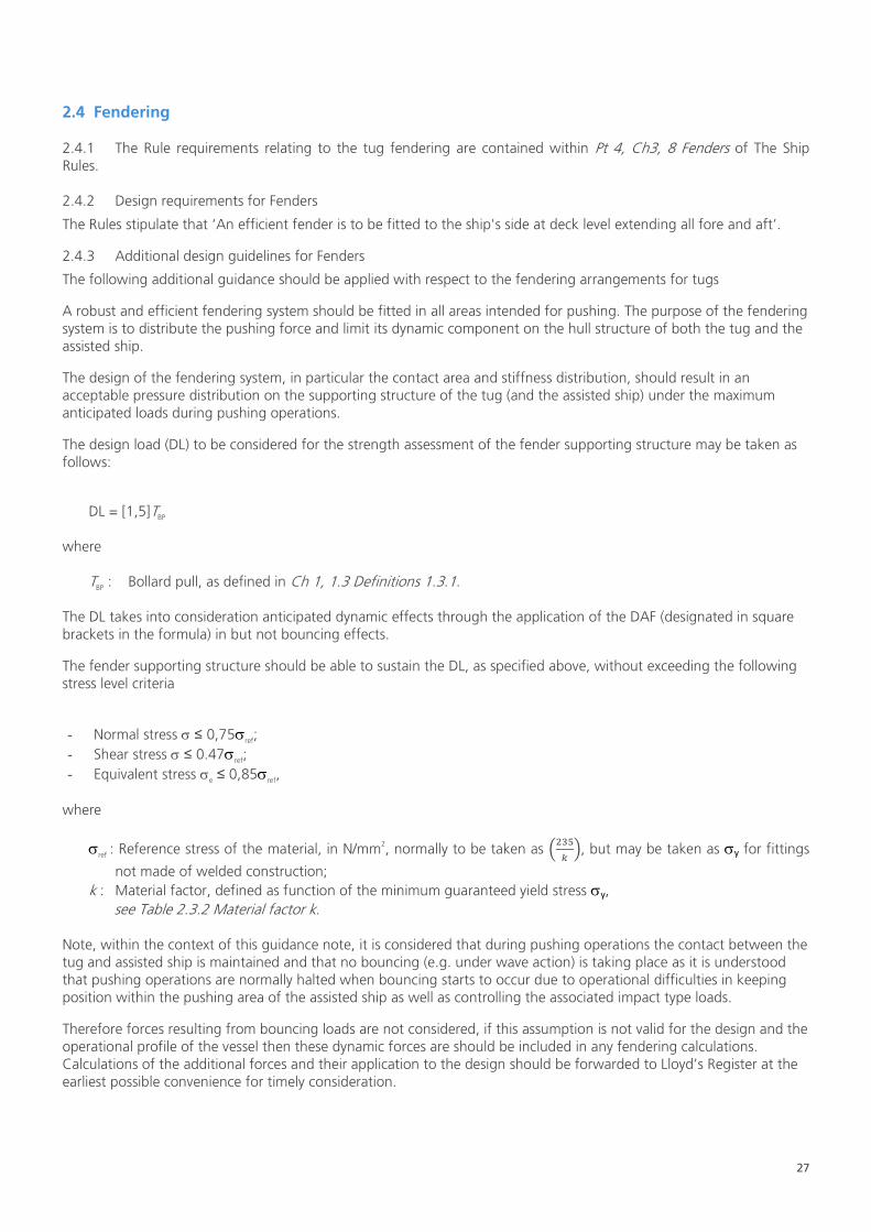
27
2.4 Fendering 2.4.1 The Rule requirements relating to the tug fendering are contained within Pt 4, Ch3, 8 Fenders of The Ship Rules. 2.4.2 Design requirements for Fenders
The Rules stipulate that ‘An efficient fender is to be fitted to the ship's side at deck level extending all fore and aft’.
2.4.3 Additional design guidelines for Fenders
The following additional guidance should be applied with respect to the fendering arrangements for tugs
A robust and efficient fendering system should be fitted in all areas intended for pushing. The purpose of the fendering system is to distribute the pushing force and limit its dynamic component on the hull structure of both the tug and the assisted ship.
The design of the fendering system, in particular the contact area and stiffness distribution, should result in an acceptable pressure distribution on the supporting structure of the tug (and the assisted ship) under the maximum anticipated loads during pushing operations.
The design load (DL) to be considered for the strength assessment of the fender supporting structure may be taken as follows:
DL = [1,5]TBP
where
TBP : Bollard pull, as defined in Ch 1, 1.3 Definitions 1.3.1. The DL takes into consideration anticipated dynamic effects through the application of the DAF (designated in square brackets in the formula) in but not bouncing effects.
The fender supporting structure should be able to sustain the DL, as specified above, without exceeding the following stress level criteria
- Normal stress σ ≤ 0,75σref; - Shear stress σ ≤ 0.47σref; - Equivalent stress σe ≤ 0,85σref,
where
σref : Reference stress of the material, in N/mm2, normally to be taken as �235𝑘�, but may be taken as σy for fittings
not made of welded construction; k : Material factor, defined as function of the minimum guaranteed yield stress σy,
see Table 2.3.2 Material factor k. Note, within the context of this guidance note, it is considered that during pushing operations the contact between the tug and assisted ship is maintained and that no bouncing (e.g. under wave action) is taking place as it is understood that pushing operations are normally halted when bouncing starts to occur due to operational difficulties in keeping position within the pushing area of the assisted ship as well as controlling the associated impact type loads.
Therefore forces resulting from bouncing loads are not considered, if this assumption is not valid for the design and the operational profile of the vessel then these dynamic forces are should be included in any fendering calculations. Calculations of the additional forces and their application to the design should be forwarded to Lloyd’s Register at the earliest possible convenience for timely consideration.
28
2.5 Escort operation performance numeral and trials 2.5.1 For Escort tugs, Lloyd’s Register offers the specific notations EPN (F,B,V,C) and CFD EPN (F,B,V) to denote the escort performance numeral of the vessel. In the case of EPN the escort performance numeral is obtained by full scale testing and for CFD EPN it is obtained through CFD. The EPN is made up of a series of values, i.e. (F,B,V,C). These are defined as: F: Maximum steering force, in tonnes. B: Maximum braking force, in tonnes. V: Speed, in knots, at which F and B are determined.
C: Time, in seconds, required for the escort tug in manoeuvring from maintained oblique position of the tug giving it a maximum steering force on one side of the assisted vessel to a mirror position on the other side.
Where escort performance numerals are predicted using computational fluid dynamics, the escort performance numeral ‘C’ is omitted
2.5.2 Rules references and guidance
The EPN notation is described in Pt 1, Ch 2, 2.3 Class notations (hull) 2.3.21 of the Ship Rules. The EPN trial requirements are detailed in Pt 4, Ch 3, 9.3 Performance numeral and trials of the Ship Rules. The CFD EPN requirements are detailed in Pt 4, Ch 3, 9.4 Computational Fluid Dynamics Predicted Performance of the Ship Rules. Further details on the suitable calculation of EPN through CFD are detailed in the Lloyd’s Register ShipRight Procedure titled Guidelines for CFD Escort Tug Performance.
2.6 Anchoring Equipment 2.6.1 Design requirements for Anchoring Equipment
The Classification requirements for anchoring equipment are governed by the equipment number for the vessel. For tugs this is calculated in as detailed in Pt 3, Ch 1, 7.1 Calculation of Equipment Number 7.1.5 of the Ship Rules Having calculated the vessels equipment number and in order to be entitle the vessel to the figure 1 in its character of classification, equipment is to be provided in accordance with the requirements of Table 13.7.1 Equipment in Pt 3, Ch 13, 7 Equipment of the Ship Rules. The requirements of the table vary depending on any service restrictions associated with the vessel. Attention is also drawn to Pt 3, Ch 13, 7 Equipment 7.1.2 of the Ship Rules which permits equipment differing from that listed if it is considered suitable go the particular service on which the ship is engaged. Anchors are to be of an approved design and the mass and number of anchors, length of wire rope or chain are to be in compliance with the requirements outlined in the aforementioned table. The Classification requirements for anchors, high holding power anchors and chain cables are found in following areas of the Rules for Ships respectively;
• Pt 3, Ch 13, 7.2 Anchors • Pt 3, Ch 13, 7.3 High holding power anchors • Pt 3, Ch 13, 7.4 Chain cables

29
2.6.2 Additional design guidelines for anchors The design of all anchor heads should be such so as to minimise stress concentrations, and in particular, the radii on all parts of cast anchor heads should be as large as possible, especially where there is considerable change of section. Anchors which must be specially laid the right way up, or which require the fluke angle or profile to be adjusted for varying types of sea bed, will not generally be considered for normal ship use. The number of anchors and chain cables which should be carried should generally be in line with the aforementioned Table 13.7.1 Equipment in Pt 3, Ch 13, 7 Equipment of the Ship Rules. However for vessels with the type notation tug which are limited to operations within protected waters or extended protected waters Lloyd’s Register will specially consider a reducing the required number of required anchors and chain cables to 1. Lloyds Register may further specially consider a reduction of the number of anchors and chain cables as depicted in Table 2.3.3 Reduced number of anchors and chain cables based on redundancy principles. Basis of this consideration will be the service and operational restrictions of the vessel and the levels of redundancy on board, for example:
- The tug is equipped with at least twin propulsion, of which each main engine can maintain sufficient propulsion
power to safely return to berth. For this purpose, the main engines should be able to run self-supporting, i.e. independent of generator sets intended for auxiliary power, unless these are able to run parallel and, in case of black-out, have automatic starting and connecting to switchboard within 45 seconds;
- A single failure, except fire, should not cause total propulsion failure; - A fixed fire-fighting installation is provided.
Type notation Service restriction notation Nr tug Protected waters/Extended protected waters 0
Tug Specified coastal service, or Specified operating or service areas
1
Tug (unrestricted) 2 escort tug Any 1 escort tug (unrestricted) 2
Table 2.3.3 Reduced number of anchors and chain cables based on redundancy principles
Lloyd’s register will specially consider the case where a spare anchor is supplied as an alternative to a second bower anchor. In such cases special provisions, such as a crane and suitable storage space for the spare anchor, should be present on board. For tugs with a service restriction notation denoting that they are restricted to operations within protected waters or extended protected waters, effectively operating in a fixed and limited area, Lloyd’s Register will specially consider the case that the spare anchor is stored ashore.

30
2.7 Machinery and Electrotechnical systems 2.7.1 All mechanical and Electrotechnical systems are to be in compliance with the relevant requirements within the Rules.
Which Rules are applicable to the vessel is dependent on the mechanical and electrical outfit of the vessel.
2.8 Fire protection, detection and extinction 2.8.1 The requirements for Fire protection, detection and extinction are contained within Pt 6, Ch 4 Fire Protection, Detection and Extinction Requirements of the Ship Rules.
2.8.2 Both the Class Rules and statute stipulate that tugs of 500 gross tons or more, on international voyages, where provision is made within International Conventions, are to be provided with the fire safety measures required by the International Convention for the Safety of Life at Sea, 1974, as amended. In addition, the Class Rules stipulate that tugs of 500 gross tons or more employed on national voyages are to comply with the fire safety measures prescribed and approved by the Government of the Flag State. 2.8.3 For tugs of less than 500 gross tons The Ship Rules also contain relevant requirements in Pt 6, Ch 4, 2 Fire Protection, Detection and Extinction. The content of this section is within the spirit of the International Convention and Protocol requirements for ships of Convention size. However it is to be noted that the content of this section are “intended to apply to new and, as far as reasonable and practicable, or as found necessary by the relevant Administration, to existing cargo ships of less than 500 GT.”. As such, consideration will be given to the acceptance of fire safety measures prescribed and approved by the Government of the Flag State instead. Ch 3, 4.1Fire safety for tugs of less than 500 GT of this document includes Lloyd’s Register supported fire protection, detection and extinction minimum standard guidance.

31
Chapter 3 – Statutory
Section 1 – Scope
1.1 Statute and this Guidance note 1.1.1 This chapter has been included in this guidance note in order to provide guidance on the statutory aspects related to the design, outfit and operation of tugs. 1.1.2 Despite the content of this chapter, in all cases the Flag Administration statutory requirements are to be met. In cases where there is an incompatibility between the content of this chapter and the Flag Administration requirements or where Lloyds’ Register is not authorised by a particular Flag Administration, the requirements and guidance of the Flag Administration take precedent over any statutory guidance presented in this document. 1.1.3 In the absence of Flag Administration requirements the Administration may choose to use the content of this chapter, in part or in full, as the basis for a set of requirements which are to be met before the vessel is registered with the Administration. In such a case early discussion with the flag is highly recommended.
32
Section 2 - Stability
2.1 Scope of application In general, tugs having a Load Line length LLL equal to or greater than 24 m may be assigned class only after it has been demonstrated that their intact stability is adequate. Adequate intact stability means compliance with standards laid down by the relevant Administration. The content of this Section may also be applied to tugs with a Load Line length LLL of less than 24 m in length as desired.
2.2 Openings 2.2.1 General Openings in the hull, superstructures or deckhouses which cannot be closed weathertight should be considered as unprotected openings and, consequently, as down-flooding points for the purpose of stability calculations (the lower edge of such openings should to be taken into account). 2.2.2 Ventilation openings of machinery space and emergency generator room It is recognised that for tugs, due to their size and arrangement, compliance with the requirements of ICLL Reg. 17(3) for ventilators necessary to continuously supply the machinery space and the emergency generator room may not be practicable. Lesser heights of the coamings of these particular openings may be accepted by the administration if the openings: - are positioned as close to the centreline and as high above the deck as practicable in order to maximise the down-
flooding angle and to minimise exposure to green water; - are provided with weathertight closing appliances in combination with suitable arrangements, such as separators
fitted with drains; - are equipped with efficient protective louvers and mist eliminators; - have a coaming height of not less than 900 mm above the deck; - are considered as unprotected openings and, consequently, as down-flooding points for the purpose of stability
calculations.
33
2.3 Intact stability 2.3.1 Loading conditions The following standard loading conditions should be included in the stability booklet: - lightship condition; - tug in lightest anticipated loading condition, with full stores and fuel; - same condition as above, but with 10 per cent stores, provisions and consumables; - tug in the departure condition at the waterline corresponding to the maximum draught, with full stores,
provisions and consumables; - same condition as above, but with 10 per cent stores, provisions and consumables.
For the lightship condition, not being an operational loading condition, the administration may accept that part of the mentioned criteria is not fulfilled. In case a tug is fitted with water ballast tanks the lightest anticipated loading condition may be a ballast condition (in particular for larger tugs). When a tropical freeboard is to be assigned to the tug, the corresponding loading conditions should also be included. For the loading condition corresponding to the maximum draught, when necessary, deck cargo may be applied to arrive at the required draught. Attention should be paid to the associated wind profile for verification of the severe wind and rolling criterion, refer to part A, 2.3 of the International Code on Intact Stability, 2008. Additional loading conditions that should be included in the stability booklet: - tug in the worst anticipated operating conditions for towing, covering the relevant range of draughts, for type
notation tug; - tug in the worst anticipated operating conditions for escorting, covering the relevant range of draughts, for type
notation escort tug. Further loading conditions may be included when deemed necessary or useful by the administration. 2.3.2 Stability criteria The intact stability of tugs should comply with the provisions given in part A, 2.2 and 2.3 of the International Code on Intact Stability, 2008, except that the alternative criteria given in part B, 2.4.5, which apply to offshore supply vessels, may be used for tugs of similar design and characteristics. With reference to Part B, 5.1.4 of the International Code on Intact Stability, 2008, tugs should possess an adequate reserve of stability to withstand the anticipated heeling moment arising from the towline. It is considered that this requirement is complied with in case a tug meets the additional stability criteria as specified in Ch 3, 2.3 Intact stability 2.3.3 and/or Ch 3, 2.3 Intact stability 2.3.4, as applicable. 2.3.3 Additional stability criteria for type notation tug All the loading conditions reported in the trim and stability booklet which are intended for towing operations should also be checked in order to investigate the tug’s capability to withstand the effect of the transverse heeling moment induced by the combined action of the towline force and the thrust vector (self-tripping), and induced by the hydrodynamic resistance of the hull (tow-tripping). The stability calculations should to be performed on the basis of the design bollard pull, as defined in Ch 1, 1.3 Definitions 1.3.1. For tugs capable of towing over the stern as well as over the bow, this check should be performed for both towing situations, duly taking into account the location of the associated towing points. If different values of the ahead and astern design bollard pull are available, it may be acceptable to consider the ahead bollard pull for towing over the stern and the astern bollard pull for towing over the bow. The values of the ahead and astern design bollard pull, as applicable, should be specified by the designer in the stability booklet. In addition, an arrangement drawing with the location of the towing point(s) and propulsion unit(s) should be included in the stability booklet. In this drawing the longitudinal and vertical distance, in m, from each of the towing points to the relevant centrelines of the propulsion unit(s) and the baseline, respectively, should be clearly specified.

34
Preliminary stability calculations on the basis of estimated bollard pull values may be submitted for (preliminary) examination. If after completion of the bollard pull test the measured bollard pull values exceed the estimated values, the stability calculations should be updated for the measured bollard pull values. It is recommended to include a reasonable margin in the estimated values (on the basis of design experience). A tug may be considered as having sufficient stability to withstand the self-tripping heeling moment if the following condition is satisfied with (see Figure 2.3.1 Heeling and righting arm curves):
A ≥ B where
A : Area, in m rad, contained between the righting arm and the heeling arm curves, measured from the heeling angle θC to the heeling angle θD;
B : Area, in m rad, contained between the heeling arm and the righting arm curves, measured from zero heel (θ = 0) to the heeling angle θC;
θC : Heeling angle of equilibrium, corresponding to the first intersection between heeling and righting arm curves;
θD : Heeling angle, to be taken as the lesser of: - heeling angle corresponding to the second intersection between heeling and righting arms heeling and
righting arm curves; - angle of down-flooding.
Figure 2.3.1: Heeling and righting arm curves
The self-tripping heeling arm curve should be calculated as follows:
bH = ΣbHi
where bHi : Heeling arm induced by one thruster or group of thrusters i, in m, calculated as follows:
∆−
=81.9
)sincos( iiBPiHi
θθ rhcTb
TBPi : Amount of thrust, in kN, generated by one thruster or group of thrusters i. The sum of all the individual thrusts is to be equal to the design bollard pull, as defined in Ch 1, 1.3 Definitions 1.3.1;
hi : Vertical distance, in m, between the towing point (fairlead, staple, towing hook or equivalent fitting) and the horizontal centreline of the propulsion unit or group of units i, as relevant for the considered towing situation;
r : Transverse distance, in m, between the centreline and the towing point (fairlead, staple, towing hook or equivalent fitting), to be taken equal to zero when the towing point is fixed at the vessel’s centreline;
ci : Coefficient to be taken equal to: - ci = 0,50 for tugs with non-azimuth propulsion unit or group of units (conventional tug, see Ch 1, 2.2
Typical tug arrangements 2.2.2); - ci = 1/(1 + di/LLL ) for a single azimuthing thruster

35
- ci = 0,90/(1 + di/LLL) for tugs with a group of two azimuthing thrusters (tractor tug and ASD tug, see Ch 1, 2.2 Typical tug arrangements 2.2.3 and Ch 1, 2.2 Typical tug arrangements 2.2.4, respectively, as well as similar tug designs), as relevant for the considered towing situation, but is in no case to be taken as less than:
- 0,70 for ASD tugs towing over the stern and tractor tugs towing over the bow - 0,50 for ASD tugs towing over the bow and tractor tugs towing over the stern, respectively;
∆ : Loading condition displacement, in t; ϴ : Angle of heel, in deg; di : Longitudinal distance, in m, between the towing point (fairlead, staple, towing hook or equivalent fitting)
and the vertical centreline of the propulsion unit or group of units i, as relevant for the considered towing situation;
LLL : Load Line length, in m. A tug may be considered as having sufficient stability to withstand the tow-tripping heeling moment if the first intersection between the righting arm curve and the tow-tripping heeling arm curve occurs at an angle of heel less than the angle of down-flooding. The tow-tripping heeling arm curve is to be calculated as follows:
∆+−
=62.19
)sincos( 3p2
21 TCrhAVCCbH
θθγ
where C1 : Lateral traction coefficient, taken equal to:
−= 1.08.2
pp
s1 L
LC
without being taken lower than 0,1 and greater than 1; Ls : Longitudinal distance, in m, from the aft perpendicular to the towing point; Lpp : Length between perpendiculars, in m; C2 : Angle of heel correction for C1, taken equal to:
+
θθ
= 5.03 d
2C
without being taken lower than 1;
ϴd : Angle to deck edge, in deg, taken equal to:
=θ
Bfa 2tand ;
f : Freeboard amidships, in m; γ : Specific water density, in t/m3, to be taken equal to 1,025; V : Lateral velocity, in m/s, to be taken equal to 2,57 (5 kn); Ap : Lateral projected area, in m2, of the underwater hull; C3 : Distance from the centre of Ap to the waterline as a fraction of the draught related to the heeling angle, taken
equal to:
3.026.0d
3 +
θθ
=C
without being taken lower than 0,5 and greater than 0,83; T : Loading condition draught, in m.
36
2.3.4 Additional stability criteria for type notation escort tug All the loading conditions reported in the trim and stability booklet which are intended for escorting operations should also be checked in order to investigate the tug’s capability to withstand the effect of the transverse heeling moment induced by the combined action of the following forces: - hydrodynamic forces acting on the hull and appendices; - thrust forces; - steady towline force.
The stability calculations should to be performed on the basis of the highest anticipated heeling moment for the considered loading condition, which should to be obtained from the results of full scale tests, model tests, or, alternatively; the results of an accepted computer simulation program (refer to Ch 3, 2.3 Intact stability 2.3.5).
For each relevant loading condition the evaluation of the highest anticipated heeling moment should be performed for the applicable range of speeds and towline angles, as defined in the escort towing arrangement plan (see Ch 2, 2.3 Towing arrangements for Escort Tugs 2.3.4). As a minimum, the conditions corresponding to the design maximum steering force Fs,MAX, and design maximum braking force Fb,MAX, as defined in Ch 1, 1.3 Definitions 1.3.2, should be included in the evaluation.
The highest anticipated heeling moment should be assumed constant for the purpose of the stability calculations.
The value of the highest anticipated heeling moment should be specified by the designer in the stability calculations. In addition, an arrangement drawing with the location of the towing points and propulsion units should be included in the stability booklet. In this drawing the longitudinal and vertical distance, in m, from the towing point to the relevant centrelines of the propulsion units and the baseline, respectively, should be clearly specified. Preliminary stability calculations on the basis of estimated highest heeling moment and associated heeling arm values may be submitted for (preliminary) examination. If after verification of the heeling arm values on the basis of the results of escort performance trials, model tests or an accepted computer simulation program (refer to Ch 3, 2.3 Intact stability 2.3.5) the final values exceed the estimated values, the stability calculations should be updated for the final heeling moment and heeling arm values. It is recommended to include a reasonable margin in the estimated values (on the basis of design experience). An escort tug may be considered as having sufficient stability to withstand the heeling moment arising from the towline, if the three following conditions are satisfied with:
A ≥ 1,25B C ≥ 1,40D θC ≤ 15 deg
where
A : Righting arm curve area, in m rad, measured from the heeling angle θC to a heeling angle of 20 deg (see Figure 2.3.2 Definition of areas A and B);
B : Heeling arm curve area, in m rad, measured from the heeling angle θC to a heeling angle 20 deg (see Figure 2.3.2 Definition of areas A and B);
C : Righting arm curve area, in m rad, measured from the zero heel (θ = 0) to the heeling angle θD (see Figure 2.3.3 Definition of areas C and D);
D : Heeling arm curve area, in m rad, measured from zero heel (θ = 0) to the heeling angle θD (see Figure 2.3.3 Definition of areas C and D);
θC : Heeling angle of equilibrium corresponding to the first intersection between heeling arm and righting arm curve, to be obtained when the highest anticipated heeling moment resulting from the steady towline force Ft
as defined in Ch 1, 1.3 Definitions 1.3.2, is applied to the escort tug; θD : Heeling angle, to be taken as the lesser of:
- the angle of down-flooding; - 40 deg; - the heeling angle corresponding to the second intersection between heeling and righting arms heeling
and righting arm curves.
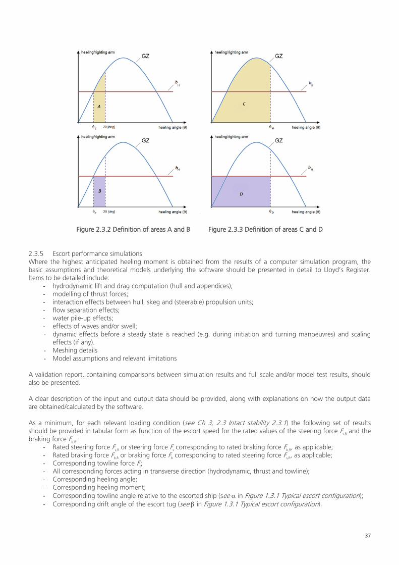
37
Figure 2.3.2 Definition of areas A and B Figure 2.3.3 Definition of areas C and D
2.3.5 Escort performance simulations Where the highest anticipated heeling moment is obtained from the results of a computer simulation program, the basic assumptions and theoretical models underlying the software should be presented in detail to Lloyd’s Register. Items to be detailed include:
- hydrodynamic lift and drag computation (hull and appendices); - modelling of thrust forces; - interaction effects between hull, skeg and (steerable) propulsion units; - flow separation effects; - water pile-up effects; - effects of waves and/or swell; - dynamic effects before a steady state is reached (e.g. during initiation and turning manoeuvres) and scaling
effects (if any). - Meshing details - Model assumptions and relevant limitations
A validation report, containing comparisons between simulation results and full scale and/or model test results, should also be presented. A clear description of the input and output data should be provided, along with explanations on how the output data are obtained/calculated by the software. As a minimum, for each relevant loading condition (see Ch 3, 2.3 Intact stability 2.3.1) the following set of results should be provided in tabular form as function of the escort speed for the rated values of the steering force Fs,R and the braking force Fb,R:
- Rated steering force Fs,R or steering force Fs corresponding to rated braking force Fb,R, as applicable; - Rated braking force Fb,R or braking force Fb corresponding to rated steering force Fs,R, as applicable; - Corresponding towline force Ft; - All corresponding forces acting in transverse direction (hydrodynamic, thrust and towline); - Corresponding heeling angle; - Corresponding heeling moment; - Corresponding towline angle relative to the escorted ship (see α in Figure 1.3.1 Typical escort configuration); - Corresponding drift angle of the escort tug (see β in Figure 1.3.1 Typical escort configuration).
38
Note that the highest anticipated values of the steering force, braking force, towline force and heeling moment do not normally all occur in the same condition (defined by the position of escort tug relative to the escorted ship and the drift angle), although more than one parameter may have its highest value in a particular condition. Hence it is suggested to consider at least two conditions: one for the highest anticipated steering force and one for the highest anticipated braking force. In case the highest anticipated heeling moment and/or towline force do not occur in either one of these two conditions, the relevant conditions should be added. It is recommended that the results of the escort performance simulations are presented in the form of diagrams showing the envelope of the (steady state) combinations of steering and braking forces obtained from the simulations. Such diagrams should cover the applicable escort speed range, with a recommended step of 2 knots. 2.3.6 Escort performance trials Escort performance trials at full scale or model scale may be carried out in order to obtain the characteristics of escort tugs. The trials should cover the applicable range of loading conditions and escort speeds. The following documents should be submitted for information prior to testing:
- Relevant loading conditions, defined by draught (or displacement) and trim, for which the tug is designed to perform escort services;
- Applicable range of test speeds of the escorted ship: the speed is defined as the relative speed with respect to the sea, taking into account current effects;
Main propulsion characteristics, in particular power and maximum orientation angle of the rudder(s) (propellers);
- Preliminary calculation of the rated steering force Fs,R, rated braking force Fb,R and rated steady towline force Ft,R as defined in Ch 1, 1.3 Definitions 1.3.2, as well as the corresponding heeling moments and heeling angles, for the range of test speeds;
- Calculation of the route deviation of the escorted ship (for testing purposes the escorted ship is to be selected so that the route deviation induced by the tug is kept reasonably small;
- Preliminary stability calculations for the above-mentioned conditions; - Escort towing arrangement plan, including the load cell and specification of the components; - Documentation relevant to the Bollard Pull test, see Ch 1, 1.3 Definitions 1.3.1.
Prior to commencing the escort performance trials the following data should be recorded:
- Wind speed and direction; - Sea state, including significant wave height and peak period; - Current speed and direction; - Water depth; - Loading condition of the escort tug: draught (or displacement) and trim; - Loading condition of the escorted ship.
Testing should be performed over the applicable range of towline angles as defined in the escort towing arrangement plan. The length of the towline and the angle of the towline with the horizontal plane should represent a typical operating condition. As a minimum, the following data should be collected during testing for post-processing and analysis:
- Towline force (tension) Ft; - Towline angle α, as defined in Figure 1.3.1 Typical escort configuration; - Drift angle β, as defined in Figure 1.3.1 Typical escort configuration; - Heeling angle of the escort tug; - Towline length and angle of towline with the horizontal plane;
39
It is also recommended to that the following data is measured: - Power setting and orientation angle of rudder(s) (propellers) of the escort tug; - Time needed to swing the tug from the equilibrium position to its mirror position.
For each combination of loading condition and test speed: - The rated steering force Fs,R and rated braking force Fb,R should be calculated on the basis of the corresponding
measured steady towline force Ft and the associated measured towline angle, drift angle and the angle between the towline and the horizontal plane;
- The maximum heeling arm should be calculated on the basis of the corresponding measured steady towline force Ft, as defined in Ch 1, 1.3 Definitions 1.3.2, the associated measured heeling angle and the GZ curve applicable to the loading condition considered (The GZ curve should be based on the escort tug in upright position before commencing the escort operation).
As a minimum, for each tested loading condition the following set of results should be provided in tabular form as a function of the escort speed for the rated values of the steering force Fs,R and the braking force Fb,R:
- Rated steering force Fs,R or steering force Fs corresponding to rated braking force Fb,R, as applicable; - Rated braking force Fb,R or braking force Fb corresponding to rated steering force Fs,R, as applicable; - Corresponding towline force Ft,R; - Corresponding heeling angle; - Corresponding heeling moment; - Corresponding towline angle relative to the escorted ship (see α in Figure 1.3.1 Typical escort configuration); - Corresponding drift angle of the escort tug (see β in Figure 1.3.1 Typical escort configuration).
The highest anticipated values of the steering force, braking force, towline force and heeling moment do not normally all occur in the same condition (defined by the position of escort tug relative to the escorted ship and the drift angle), although more than one parameter may have its highest value in a particular condition. Hence it is suggested to consider at least two conditions: one for the highest anticipated steering force and one for the highest anticipated braking force. In case the highest anticipated heeling moment and/or towline force do not occur in either one of these two conditions, the relevant conditions should be added. For model testing, due consideration should be given to scale effects for establishing the escort tug characteristics at full scale from the model test results. 2.3.7 Operating information for type notation escort tug Additional operating information should be provided in the stability booklet in relation to the design limitations related to the assignment of the type notation escort tug, in line with Pt B, Ch 3.8 of the International Code on Intact Stability, 2008. As a minimum, the following information should be included: - Design service restriction notation and environmental conditions for performing escort operations; - The maximum escort speed VMAX (see Ch 1, 1.3 Definitions 1.3.2); - A table with permissible values of heeling angle and steady towline force as function of loading condition and
escort speed (based on the rated steering and braking forces as obtained from Ch 3, 2.3 Intact stability 2.3.5 or Ch 3, 2.3 Intact stability 2.3.6, as applicable);
- Instructions to the master regarding the handling of the escort tug and the associated towing equipment, demonstrating the implementation of effective means to limiting the steady towline force and heeling angle within the permissible limits and the use of the emergency quick-release device. In this context “Effective means” might include, but is not limited to, adjustable audible or visible alarms, providing a warning to the master when the heeling angle and/or steady towline force exceeds the permissible value(s) applicable to the relevant loading condition and escort speed.
The table with permissible values of heeling angle and steady towline force as function of loading condition and escort speed should be displayed in the wheelhouse next to the control desk or another appropriate location.

40
2.3.8 Icing considerations For tugs operating in areas where ice accretion is expected due consideration should be given to the stability affecting effect of added weight due to ice accretion. To this end, relevant loading conditions, including ice accretion should be included in the stability booklet, together with detailed calculations of the expected ice accretion a required by Pt B, Ch 6 of the International Code on Intact Stability, 2008. 2.3.9 Elements reducing stability Provisions should be made for a safe margin of stability at all stages of the voyage, due regard being given to additions of weight, such as those due to absorption of water and icing and to losses of weight such as those due to consumption of fuel and stores. 2.3.10 Alterations Where any alterations are made to a tug or its towing equipment so as to materially affect the stability information supplied to the master, amended stability information should be provided. During the lifetime of the vessel, it is recommended that periodical lightweight surveys are undertaken to verify any changes in lightship displacement and longitudinal centre of gravity. In the case that case significant deviations are found in comparison with the approved stability information, it may be necessary to (re-)incline the tug and/ or reassess the strength and stability of the vessel.

41
Section 3 - Safety Equipment
3.1 Fire safety for tugs of less than 500 GT
The guidance in this Chapter has the following fire safety objectives: - Prevent the occurrence of fire and explosion; - Reduce the risk to life caused by fire; - Reduce the risk of damage caused by fire to the tug and the environment; - Contain, control and suppress fire and explosion in the compartment of origin; and - Provide adequate and readily accessible means of escape for crew.
For easy reference, a summary of the guideline requirements for tug fire safety is included as Table 3.1.4: Fire safety Guidance. 3.1.1 Fire pumps and fire main systems This guidance aims to ensure that any fire is effectively suppressed and swiftly extinguished in the space of origin. For this purpose, the following functional requirements should be met: - Fixed fire-extinguishing systems should be installed, as applicable, having due regard to the fire growth potential
of the protected spaces; and - Fire-extinguishing appliances should be readily available.
(a) Capacity The total capacity of the main fire pump(s) should not be less than:
2)170.2))((145.0( 21++= DBLQ , but need not exceed 25 m3/hour,
where
B : Greatest moulded breadth of tug, in m D : Moulded depth to bulkhead deck, in m L : Freeboard Length, in m Q : Total capacity, in m3/hour
(b) Fire pumps Generally one main power pump and one portable fire pump should be provided as specified below.
- Sanitary, ballast, bilge or general service pumps may be accepted as fire pumps, provided that they are not normally used for pumping oil, and that, if they are subject to occasional duty for the transfer or pumping of fuel oil, suitable changeover arrangements are fitted.
- A power pump is a fixed pump driven by a power source other than by hand. An independently driven power pump is independent from the main engine(s).
- Provisions should be made for clearing sea inlet gratings of fire pump sea inlet valves. Special attention should be paid to ice clearing arrangements for tugs intended for navigation in ice (e.g. air blowing, heating).
- Relief valves should be provided in conjunction with any fire pump if the pump is capable of developing a pressure exceeding the design pressure of the water service pipes, hydrants and hoses. These valves should be so placed and adjusted as to prevent excessive pressure in any part of the fire main system.
- Where a centrifugal pump is provided in order to comply with this sub-Section, a non-return valve should be fitted in the pipe connecting the pump to the fire main.

42
(c) Portable fire pumps
- Portable fire pumps should comply with the following: (i) The pump should be self-priming. (ii) The total suction head and the net positive suction head of the pump should be determined taking
account of actual operation, i.e. pump location when used. The net positive suction head of the pump should be realised at the deck where the pump is fitted (in practical cases on tugs this is typically the main deck).
(iii) The portable fire pump, when fitted with its length of discharge hose and nozzle, should be capable of maintaining a pressure sufficient to produce a jet throw of at least 12 m, or that required to enable a jet of water to be directed on any part of the engine room or the exterior boundary of the engine room and casing, whichever is the greater.
(iv) Except for electric pumps, the pump set should have its own fuel tank of sufficient capacity to operate the pump for three hours. For electric pumps, their batteries should have sufficient capacity for three hours.
(v) Except for electric pumps, details of the fuel type and storage location should be carefully considered. If the fuel type has a flashpoint below 60°C, further consideration to the fire safety aspects should be given.
(vi) The pump set should be stored in a secure, safe and enclosed space, accessible from open deck and clear of the Category ‘A’ machinery space.
(vii) The pump set should be easily moved and operated by two persons and be readily available for immediate use.
(viii) Arrangements should be provided to secure the pump at its anticipated operating position(s). (ix) The overboard suction hose should be non-collapsible and of sufficient length, to ensure suction under
all operating conditions. A suitable strainer should be fitted at the inlet end of the hose. (x) Any diesel-driven power source for the pump should be capable of being readily started in its cold
condition by hand (manual) cranking. If this is impracticable, consideration should be given to the provision and maintenance of heating arrangements, so that readily starting can be ensured.
- Alternatively to the guidance in Ch 3, 3.1 Fire safety 3.1.1 (c) (i) .to Ch 3, 3.1 Fire safety 3.1.1 (c) (x), a fixed fire pump may be fitted, which should comply with the following:
(xi) The pump, its source of power and sea connection should be located in accessible positions, outside the compartment housing the main fire pump.
(xii) The sea valve should be capable of being operated from a position near the pump. (xiii) The room where the fire pump prime mover is located should be illuminated from the emergency source
of electrical power, and should be well ventilated. (xiv) Pumps required to supply water for a fixed fire-extinguishing system in the space where the main fire
pump is situated, should be capable of simultaneously supplying water to this system and the fire main at the required rates.
(xv) The pump may also be used for other suitable purposes, subject to the approval in each case. (xvi) Pressure and quantity of water delivered by the pump should be sufficient to produce a jet of water, at
any nozzle, of not less than 12 m in length. For tugs of less than 150 GT, the jet of water may be specially considered.
- For tugs of less than 150 GT fitted with an approved fixed fire-fighting system in the engine room, portable pumps may be omitted.
- Means to illuminate the stowage area of the portable pump and its necessary areas of operation should be provided from the emergency source of electrical power.
(d) Fire main
- The diameter of the fire main should be based on the required capacity of the fixed main fire pump(s) and the diameter of the water service pipes should be sufficient to ensure an adequate supply of water for the operation of at least one fire hose.
- The wash deck line may be used as a fire main provided that the requirements of this sub-Section are satisfied. - All exposed water pipes for fire-extinguishing should be provided with drain valves for use in frosty weather.
The valves should be located where they will not be damaged by tug operations.

43
(e) Pressure in the fire main
- When the main fire pump is delivering the quantity of water required by Ch 3, 3.1 Fire safety 3.1.1 (a), or the fire pump described in Ch 3, 3.1 Fire safety 3.1.1 (c) (xi) to Ch 3, 3.1 Fire safety 3.1.1 (c) (xvi), through the fire main, fire hoses and nozzles, the pressure maintained at any hydrant should be sufficient to produce a jet throw at any nozzle of not less than 12 m in length. (For tugs of less than 150 GT, the jet of water may be specially considered).
(f) Fire hydrants
For tugs of less than 150 GT the number and position of the hydrants should be such that at least one jet of water may reach any part normally accessible to the crew, while the tug is being navigated and any part of any deck space when empty. Furthermore, such hydrants should be positioned near the accesses to the protected spaces. At least one hydrant should be provided in each Category ‘A’ machinery space.
- For tug equal to or greater than 150 GT the number and position of hydrants should be such that at least two jets of water not emanating from the same hydrant, one of which should be from a single length of hose, may reach any part of the tug normally accessible to the crew while the tug is being navigated and any part of any cargo spaces when empty. Furthermore, such hydrants should be positioned near the accesses to the protected spaces. Other Requirements specified by the Administration will additionally be considered.
(g) Pipes and hydrants
- Materials readily rendered ineffective by heat should not be used for fire mains. Where steel pipes are used, they should be galvanised internally and externally. Cast iron pipes are generally not acceptable. The pipes and hydrants should be so placed that the fire-hoses may be easily coupled to them. The arrangement of pipes and hydrants should be such as to avoid the possibility of freezing. In tugs where deck cargo may be carried, the positions of the hydrants should be such that they are always readily accessible and the pipes should be arranged, as far as practicable, to avoid risk of damage by such cargo. There should be complete interchange ability of hose couplings and nozzles.
- A valve should be fitted at each fire hydrant so that any fire-hose may be removed while the fire pump is at work.
- Where a fixed fire pump is fitted outside the engine room, in accordance with Ch 3, 3.1 Fire safety 3.1.1 (c) (xi) to Ch 3, 3.1 Fire safety 3.1.1 (c) (xvi); an isolating valve should be fitted in the fire main so that all the hydrants in the tug, except those in the Category ‘A’ machinery space, can be supplied with water. The isolating valve should be located in an easily accessible and tenable position outside the Category ‘A’ machinery space. And the fire main should not re-enter the machinery space downstream of the isolating valve.
(h) Fire-hoses
- Fire-hoses should be of approved non-perishable material. The hoses should be sufficient in length to project a jet of water to any of the spaces in which they may be required to be used. Their length, in general, should not exceed 18 m. Each hose should be provided with a nozzle and the necessary couplings. Fire-hoses, together with any necessary fittings and tools, should be kept ready for use in conspicuous positions near the water service hydrants or connections.
- One hose should be provided for each hydrant. In addition one spare hose should be provided on board.
(i) Nozzles
- For the purpose of this Chapter, standard nozzle sizes are 12 mm, 16 mm or 19 mm, or as near thereto as possible, so as to make full use of the maximum discharge capacity of the fire pump(s).
- For accommodation and service spaces, the nozzle size need not exceed 12 mm. - The size of nozzles used in conjunction with a portable fire pump need not exceed 12 mm. - All nozzles should be of an approved dual purpose type (i.e. spray/jet type) incorporating a shut-off.
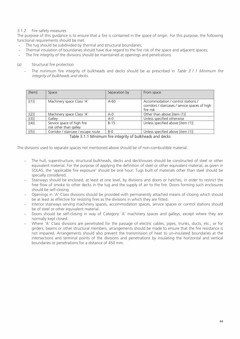
44
3.1.2 Fire safety measures The purpose of this guidance is to ensure that a fire is contained in the space of origin. For this purpose, the following functional requirements should be met: - The tug should be subdivided by thermal and structural boundaries; - Thermal insulation of boundaries should have due regard to the fire risk of the space and adjacent spaces; - The fire integrity of the divisions should be maintained at openings and penetrations.
(a) Structural fire protection
- The minimum fire integrity of bulkheads and decks should be as prescribed in Table 3.1.1 Minimum fire integrity of bulkheads and decks.
[Item] Space Separation by From space
[(1)] Machinery space Class ‘A’ A-60 Accommodation / control stations / corridors / staircases / service spaces of high fire risk
[(2)] Machinery space Class ‘A’ A-0 Other than above [item (1)] [(3)] Galley A-0 Unless specified otherwise [(4)] Service space of high fire
risk other than galley B-15
Unless specified above [item (1)]
[(5)] Corridor / staircase / escape route B-0 Unless specified above [item (1)] Table 3.1.1 Minimum fire integrity of bulkheads and decks
The divisions used to separate spaces not mentioned above should be of non-combustible material.
- The hull, superstructure, structural bulkheads, decks and deckhouses should be constructed of steel or other equivalent material. For the purpose of applying the definition of steel or other equivalent material, as given in SOLAS, the ‘applicable fire exposure’ should be one hour. Tugs built of materials other than steel should be specially considered.
- Stairways should be enclosed, at least at one level, by divisions and doors or hatches, in order to restrict the free flow of smoke to other decks in the tug and the supply of air to the fire. Doors forming such enclosures should be self-closing.
- Openings in ‘A’ Class divisions should be provided with permanently attached means of closing which should be at least as effective for resisting fires as the divisions in which they are fitted.
- Interior stairways serving machinery spaces, accommodation spaces, service spaces or control stations should be of steel or other equivalent material.
- Doors should be self-closing in way of Category ‘A’ machinery spaces and galleys, except where they are normally kept closed.
- Where ‘A’ Class divisions are penetrated for the passage of electric cables, pipes, trunks, ducts, etc., or for girders, beams or other structural members, arrangements should be made to ensure that the fire resistance is not impaired. Arrangements should also prevent the transmission of heat to un-insulated boundaries at the intersections and terminal points of the divisions and penetrations by insulating the horizontal and vertical boundaries or penetrations for a distance of 450 mm.
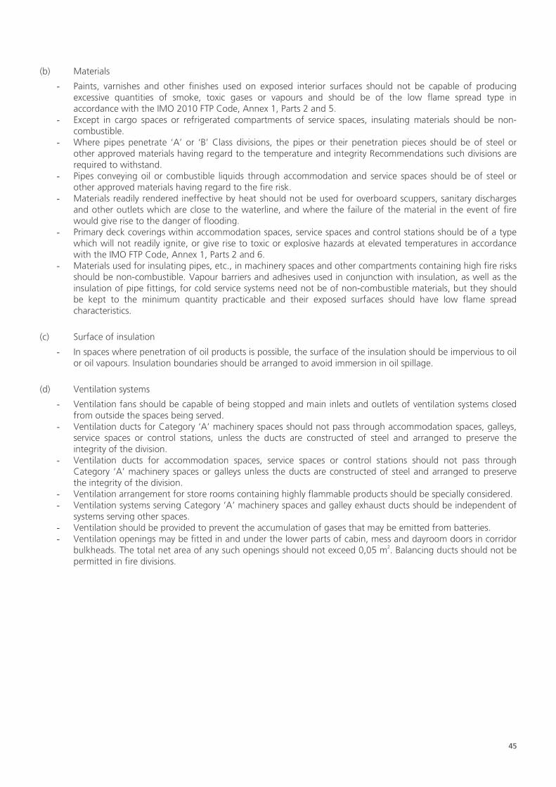
45
(b) Materials
- Paints, varnishes and other finishes used on exposed interior surfaces should not be capable of producing excessive quantities of smoke, toxic gases or vapours and should be of the low flame spread type in accordance with the IMO 2010 FTP Code, Annex 1, Parts 2 and 5.
- Except in cargo spaces or refrigerated compartments of service spaces, insulating materials should be non-combustible.
- Where pipes penetrate ‘A’ or ‘B’ Class divisions, the pipes or their penetration pieces should be of steel or other approved materials having regard to the temperature and integrity Recommendations such divisions are required to withstand.
- Pipes conveying oil or combustible liquids through accommodation and service spaces should be of steel or other approved materials having regard to the fire risk.
- Materials readily rendered ineffective by heat should not be used for overboard scuppers, sanitary discharges and other outlets which are close to the waterline, and where the failure of the material in the event of fire would give rise to the danger of flooding.
- Primary deck coverings within accommodation spaces, service spaces and control stations should be of a type which will not readily ignite, or give rise to toxic or explosive hazards at elevated temperatures in accordance with the IMO FTP Code, Annex 1, Parts 2 and 6.
- Materials used for insulating pipes, etc., in machinery spaces and other compartments containing high fire risks should be non-combustible. Vapour barriers and adhesives used in conjunction with insulation, as well as the insulation of pipe fittings, for cold service systems need not be of non-combustible materials, but they should be kept to the minimum quantity practicable and their exposed surfaces should have low flame spread characteristics.
(c) Surface of insulation
- In spaces where penetration of oil products is possible, the surface of the insulation should be impervious to oil or oil vapours. Insulation boundaries should be arranged to avoid immersion in oil spillage.
(d) Ventilation systems
- Ventilation fans should be capable of being stopped and main inlets and outlets of ventilation systems closed from outside the spaces being served.
- Ventilation ducts for Category ‘A’ machinery spaces should not pass through accommodation spaces, galleys, service spaces or control stations, unless the ducts are constructed of steel and arranged to preserve the integrity of the division.
- Ventilation ducts for accommodation spaces, service spaces or control stations should not pass through Category ‘A’ machinery spaces or galleys unless the ducts are constructed of steel and arranged to preserve the integrity of the division.
- Ventilation arrangement for store rooms containing highly flammable products should be specially considered. - Ventilation systems serving Category ‘A’ machinery spaces and galley exhaust ducts should be independent of
systems serving other spaces. - Ventilation should be provided to prevent the accumulation of gases that may be emitted from batteries. - Ventilation openings may be fitted in and under the lower parts of cabin, mess and dayroom doors in corridor
bulkheads. The total net area of any such openings should not exceed 0,05 m2. Balancing ducts should not be permitted in fire divisions.
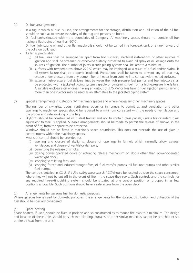
46
(e) Oil fuel arrangements
- In a tug in which oil fuel is used, the arrangements for the storage, distribution and utilisation of the oil fuel should be such as to ensure the safety of the tug and persons on board.
- Oil fuel tanks situated within the boundaries of Category ‘A’ machinery spaces should not contain oil fuel having a flashpoint of less than 60°C.
- Oil fuel, lubricating oil and other flammable oils should not be carried in a forepeak tank or a tank forward of the collision bulkhead.
- As far as practicable: (i) oil fuel lines shall be arranged far apart from hot surfaces, electrical installations or other sources of
ignition and shall be screened or otherwise suitably protected to avoid oil spray or oil leakage onto the sources of ignition. The number of joints in such piping systems shall be kept to a minimum.
(ii) surfaces with temperatures above 220°C which may be impinged as a result of a fuel and/or hydraulic oil system failure shall be properly insulated. Precautions shall be taken to prevent any oil that may escape under pressure from any pump, filter or heater from coming into contact with heated surfaces.
(iii) external high-pressure fuel delivery lines between the high pressure fuel pumps and fuel injectors shall be protected with a jacketed piping system capable of containing fuel from a high-pressure line failure. A suitable enclosure on engines having an output of 375 kW or less having fuel injection pumps serving more than one injector may be used as an alternative to the jacketed piping system.
(f) Special arrangements in Category ‘A’ machinery spaces and where necessary other machinery spaces
- The number of skylights, doors, ventilators, openings in funnels to permit exhaust ventilation and other openings to machinery spaces should be reduced to a minimum consistent with the needs of ventilation and the proper and safe working of the tug.
- Skylights should be constructed with steel frames and not to contain glass panels, unless fire-retardant glass equivalent to steel is applied. Suitable arrangements should be made to permit the release of smoke, in the event of fire, from the space to be protected.
- Windows should not be fitted in machinery space boundaries. This does not preclude the use of glass in control rooms within the machinery spaces.
- Means of control should be provided for: (i) opening and closure of skylights, closure of openings in funnels which normally allow exhaust
ventilation, and closure of ventilator dampers; (ii) permitting the release of smoke; (iii) closing power-operated doors or actuating release mechanism on doors other than power-operated
watertight doors; (iv) stopping ventilating fans; and (v) stopping forced and induced draught fans, oil fuel transfer pumps, oil fuel unit pumps and other similar
fuel pumps. - The controls detailed in Ch 3, 3.1 Fire safety measures 3.1.2(f) should be located outside the space concerned,
where they will not be cut off in the event of fire in the space they serve. Such controls and the controls for any required fire-extinguishing system should be situated at one control position or grouped in as few positions as possible. Such positions should have a safe access from the open deck.
(g) Arrangements for gaseous fuel for domestic purposes Where gaseous fuel is used for domestic purposes, the arrangements for the storage, distribution and utilisation of the fuel should be specially considered. (h) Space heating Space heaters, if used, should be fixed in position and so constructed as to reduce fire risks to a minimum. The design and location of these units should be such that clothing, curtains or other similar materials cannot be scorched or set on fire by heat from the unit.
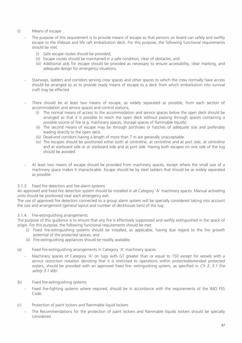
47
(i) Means of escape
- The purpose of this requirement is to provide means of escape so that persons on board can safely and swiftly escape to the lifeboat and life raft embarkation deck. For this purpose, the following functional requirements should be met:
(i) Safe escape routes should be provided; (ii) Escape routes should be maintained in a safe condition, clear of obstacles; and (iii) Additional aids for escape should be provided as necessary to ensure accessibility, clear marking, and
adequate design for emergency situations.
- Stairways, ladders and corridors serving crew spaces and other spaces to which the crew normally have access should be arranged so as to provide ready means of escape to a deck from which embarkation into survival craft may be effected.
- There should be at least two means of escape, as widely separated as possible, from each section of accommodation and service spaces and control stations,
(i) The normal means of access to the accommodation and service spaces below the open deck should be arranged so that it is possible to reach the open deck without passing through spaces containing a possible source of fire (e.g. machinery spaces, storage spaces of flammable liquids).
(ii) The second means of escape may be through portholes or hatches of adequate size and preferably leading directly to the open deck.
(iii) Dead-end corridors having a length of more than 7 m are generally unacceptable. (iv) The escapes should be positioned either both at centreline, at centreline and at port side, at centreline
and at starboard side or at starboard side and at port side. Having both escapes on one side of the tug should be avoided.
- At least two means of escape should be provided from machinery spaces, except where the small size of a machinery space makes it impracticable. Escape should be by steel ladders that should be as widely separated as possible.
3.1.3 Fixed fire detection and fire-alarm systems An approved and fixed fire detection system should be installed in all Category ‘A’ machinery spaces. Manual activating units should be positioned near each emergency exit. The use of approved fire detectors connected to a group alarm system will be specially considered taking into account the size and arrangement (general layout and number of deckhouse tiers) of the tug. 3.1.4 Fire-extinguishing arrangements The purpose of this guidance is to ensure that any fire is effectively suppressed and swiftly extinguished in the space of origin. For this purpose, the following functional requirements should be met:
(i) Fixed fire-extinguishing systems should be installed, as applicable, having due regard to the fire growth potential of the protected spaces; and
(ii) Fire-extinguishing appliances should be readily available. (a) Fixed fire-extinguishing arrangements in Category ‘A’ machinery spaces
- Machinery spaces of Category ‘A’ on tugs with GT greater than or equal to 150 except for vessels with a service restriction notation denoting that it is restricted to operations within protected/extended protected waters, should be provided with an approved fixed fire- extinguishing system, as specified in Ch 3, 3.1 Fire safety 3.1.4(b)
(b) Fixed fire-extinguishing systems
- Fixed fire-fighting systems where required, should be in accordance with the requirements of the IMO FSS Code.
(c) Protection of paint lockers and flammable liquid lockers
- The Recommendations for the protection of paint lockers and flammable liquids lockers should be specially considered.

48
(d) Other fixed fire-extinguishing systems (not covered by this Chapter)
- If such a system is installed, it should be of an approved type.
(e) Portable fire-extinguishers
- The number of portable fire-extinguishers that should be carried on board are detailed in Table 3.1.2 Portable fire-extinguishers
Accommodation and service spaces - Tugs greater than or equal to 150 GT - Tugs of less than 150 GT
≥ 3 ≥ 1
Boiler rooms etc. ≥ 2 Machinery spaces (one extinguisher per every 375 kW of internal combustion engine power)
≥ 2, ≤ 6
Table 3.1.2: Portable fire-extinguishers
- All fire-extinguishers should be of approved types and designs. - The extinguishing media employed should be suitable for extinguishing fires in the compartments in which
they are intended to be used. - The extinguishers required for use in the machinery spaces of tugs using oil as fuel should be of a type
discharging foam, carbon dioxide gas, dry powder or other approved media suitable for extinguishing oil fires. - The capacity of required portable fluid extinguishers should not exceed more than 13,5 litres but not less than
9 litres. Other extinguishers should be at least as portable as the 13,5 litre fluid extinguishers, and should have a fire-extinguishing capability at least equivalent to a 9 litre fluid extinguisher.
- The following capacities may be taken as equivalents:
(i) 9 litre fluid extinguisher (water or foam); (ii) 5 kg dry powder; (iii) 5 kg carbon dioxide.
- A spare charge should be provided for each required portable fire-extinguisher that can be readily recharged on board. If this cannot be done, duplicate extinguishers should be provided.
- The extinguishers should be stowed in readily accessible positions and should be spread as widely as possible and not be grouped.
- One of the portable fire-extinguishers intended for use in any space should be stowed near the entrance to that space.
- Accommodation spaces, service spaces and control stations should be provided with a sufficient number of portable fire-extinguishers to ensure that at least one extinguisher will be readily available for use in every compartment of the crew spaces. In any case, their number should be not less than three, except where this is impractical for very small tugs, in which case one extinguisher should be available at each deck having accommodation or service spaces, or control stations.
- Portable fire-extinguishers using C02 are not to be used in accommodation spaces.

49
3.1.5 Fire-fighting equipment Fire-fighting equipment should be available as detailed below: (a) Fire-fighter’s outfit (which includes an axe)
- For all vessels of 150 GT or greater at least two fire-fighter’s outfits complying with the Requirements of the IMO FSS Code, should be provided on board.
- For vessels of less than 150 GT at least one fire-fighter’s outfit complying with the Requirements of the IMO FSS Code, should be provided on board. Except for vessels of less than 150 GT with a service restriction notation denoting that it is restricted to operations within protected/ extended protected waters, where no fire-fighter’s outfit is required, however a Firefighters axe should still be carried.
(b) Fire control plans
- In all tugs, general arrangement plans should be permanently exhibited for the guidance of the tug's officers, using graphical symbols that are in accordance with IMO Resolution A.952(23), which show clearly for each deck the control stations, the various fire sections enclosed by steel or ‘A’ Class divisions, together with particulars of:
- The fire detection and fire-alarm systems; - Fixed fire-fighting system; - The fire-extinguishing appliances; - The means of access to different compartments, decks, etc.; - The position of the fireman's outfits; - The ventilating system, including particulars of the fan control positions, the position of dampers and
identification numbers of the ventilating fans serving each section; and - The location and arrangement of the emergency stop for the oil fuel unit pumps and for closing the
valves on the pipes from oil fuel tanks.
- Alternatively, the details may be set out in a booklet, a copy of which should be supplied to each officer, with one copy at all times available on board in an accessible position.
- The plans and booklets should be kept up to date, any alterations being recorded thereon as soon as practicable. Description in such plans and booklets should be in the official language of the Flag State and in the language as shown in Table 3.1.3 Language in fire control plan. In addition, instructions concerning the maintenance and operation of all the equipment and installations on board for the fighting and containment of fire should be kept under one cover, readily available in an accessible position.
Notations Language
tug, escort tug English tug, escort tug with a service restriction notation
Official language(s) of the Administration(s) concerned with the tug’s service, or language(s) recognised by such Administration(s). However, description in such plans and booklets for tugs engaged in domestic service only may be in the official language of the Flag State only.
Table 3.1.3 Language in fire control plan
- In general, on all vessels greater than or equal to 150 GT, a duplicate set of fire-control plans or a booklet containing such plans should be permanently stored in a prominently marked weather tight enclosure outside the deckhouse for the assistance of shore-side fire-fighting personnel.
- For vessels with a service restriction notation denoting that it is restricted to operations within protected/extended protected waters the duplicate set of the fire-control plan may be stored at a shore side facility.

50
3.1.6 Alternative design and arrangements for fire safety The purpose of this guidance is to provide a methodology for alternative design and arrangements for fire safety. (a) General
- Fire safety design and arrangements that deviate from Ch 3, 3.1 Fire safety 3.1.1 to Ch 3, 3.1 Fire safety 3.1.6, should meet the following fire safety objectives and the functional Recommendations.
- When fire safety design or arrangements deviate from the requirements of this Chapter, engineering analysis, evaluation and approval of the alternative design and arrangements should be carried out in accordance with this part of the guidance. Reference can be made to MSC/Circ.1002 ‘Guidelines on alternative design and arrangements for fire safety’.
(b) Engineering analysis
- The engineering analysis should be prepared and submitted, based on the guidelines developed by the International Maritime Organization (IMO) and should include, as a minimum, the following elements:
(i) determination of the tug type and space(s) concerned; (ii) identification of recommendation(s) with which the tug or the space(s) will not comply; (iii) identification of the fire and explosion hazards of the tug or the space(s) concerned:
- identification of the possible ignition sources; - identification of the fire growth potential of each space concerned; - identification of the smoke and toxic effluent generation potential for each space concerned; - identification of the potential for the spread of fire, smoke or of toxic effluents from the space(s)
concerned to other spaces;
(iv) determination of the required fire safety performance criteria for the tug or the space(s) concerned:
- performance criteria should be based on the fire safety objectives and on the functional Recommendations of this Chapter;
- performance criteria should provide a degree of safety not less than that achieved the Recommendation in Ch 3, 3.1 Fire safety 3.1.1 to Ch 3, 3.1 Fire safety 3.1.6; and
- performance criteria should be quantifiable and measurable;
(v) detailed description of the alternative design and arrangements, including a list of the assumptions used in the design and any proposed operational restrictions or conditions; and
(vi) technical justification demonstrating that the alternative design and arrangements meet the required fire safety performance criteria.
(c) Evaluation of the alternative design and arrangements
- The engineering analysis required in Ch 3, 3.1 Fire safety 3.1.6 (b) should be appraised by the relevant body (e.g. Class) taking into account the guidelines developed by the IMO.
- A copy of the documentation, as appraised, indicating that the alternative design and arrangements comply with this regulation should be carried on board the tug.
(d) Re-evaluation due to change of conditions
- If the assumptions or operational restrictions that were stipulated in the alternative design and arrangements are changed, the engineering analysis should be carried out considering the updated condition and should be submitted for evaluation.
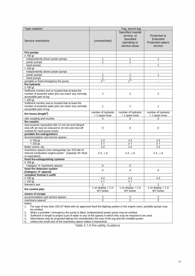
51
Type notation Tug, escort tug
Service restrictions (unrestricted)
Specified coastal service, or Specified
operating or service areas
Protected or Extended
Protected waters service
Fire pumps ≥ 150 gt
independently driven power pumps 1 1 1 power pumps 1 1 - hand pumps - - 1
< 150 gt independently driven power pumps - - - power pumps 1 1 1 hand pumps 1 1 -
portable or fixed emergency fire pump 11,2 11,2 - fire hydrants ≥ 150 gt Sufficient number and so located that at least the number of powerful water jets can reach any normally accessible part of tug
2 2 2
< 150 gt Sufficient number and so located that at least the number of powerful water jets can reach any normally accessible part of tug
1 1 1
fire hoses (length3) number of hydrants + 1 spare hose
number of hydrants + 1 spare hose
number of hydrants + 1 spare hose
with coupling and nozzles X X X fire nozzles dual purpose (spray/jet) with 12 mm jet and integral shut-off; jet may be reduced to 10 mm and shut-off omitted for hand pump hoses
X X X
portable fire-extinguishers Accommodation and service spaces
≥ 150 gt ≥ 3 ≥ 3 ≥ 3 < 150 gt ≥ 1 ≥ 1 ≥ 1
Boiler rooms, etc. ≥ 2 ≥ 2 ≥ 2 machinery spaces (one extinguisher per 375 kW of internal combustion engine power4 (capacity 45 l fluid or equivalent)
≥ 2 , ≤ 6 ≥ 2 , ≤ 6 ≥ 2 , ≤ 6
fixed fire-extinguishing systems ≥ 150 gt
Category ‘A’ machinery spaces X X - fixed fire detection system (Category ‘A’ spaces) X X X
complete fireman’s outfit ≥ 150 gt ≥ 2 ≥ 2 ≥ 2 < 150 gt ≥ 1 ≥ 1 - fireman’s axe 1 1 1
fire control plan 1 on display + 1 in WT locker
1 on display + 1 in WT locker
1 on display + 1 in WT locker
means of escape accommodation and service spaces 2 2 2 machinery spaces5 2 2 2 Notes: 1. For tugs of less than 150 GT fitted with an approved fixed fire-fighting system in the engine room, portable pumps may
be omitted. 2. When a portable / emergency fire pump is fitted, (independent) power pump may be omitted. 3. Sufficient in length to project a jet of water to any of the spaces in which they may be required to be used. 4. Alternatives may be proposed taking into consideration the size of the tug and the installed power. 5. Unless the small size of the machinery space makes it impractical.
Table 3.1.4 Fire safety Guidance
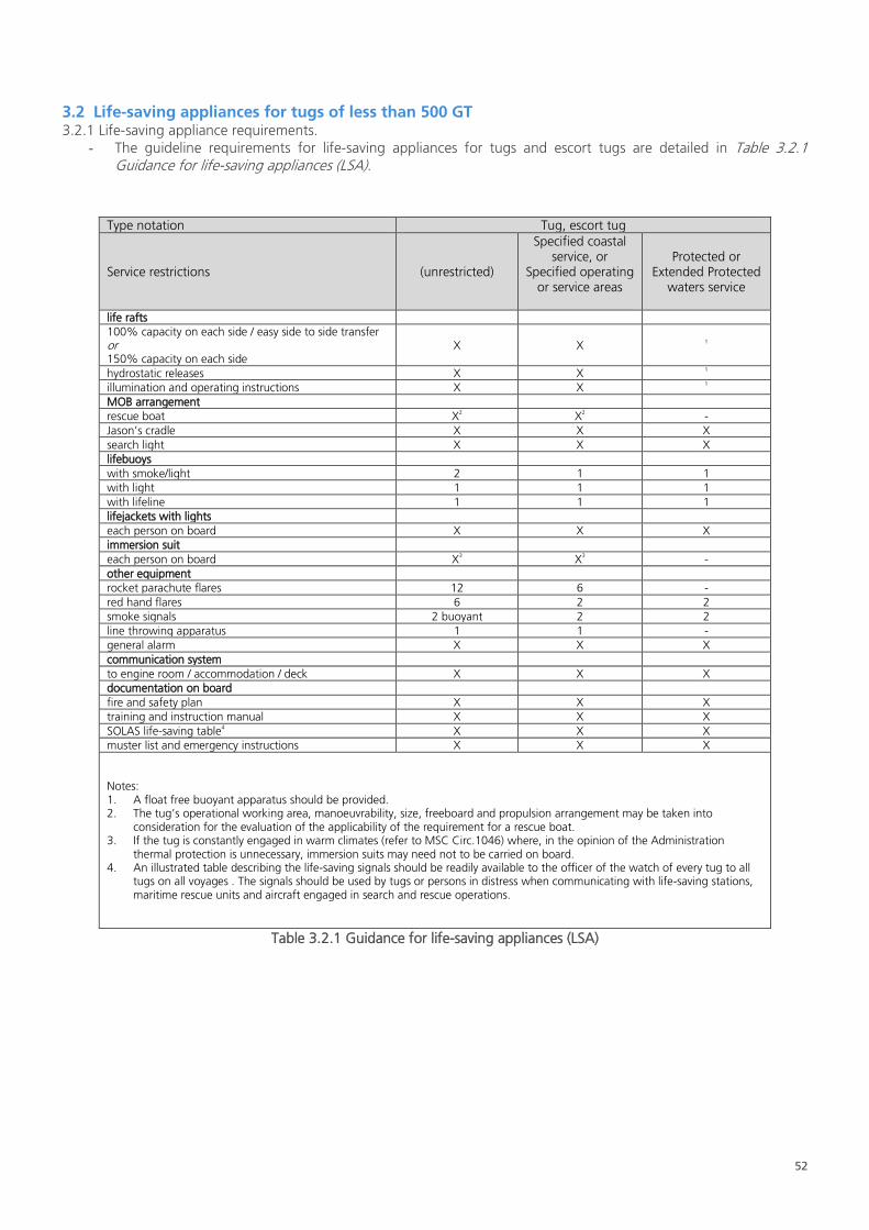
52
3.2 Life-saving appliances for tugs of less than 500 GT 3.2.1 Life-saving appliance requirements.
- The guideline requirements for life-saving appliances for tugs and escort tugs are detailed in Table 3.2.1 Guidance for life-saving appliances (LSA).
Type notation Tug, escort tug
Service restrictions (unrestricted)
Specified coastal service, or
Specified operating or service areas
Protected or Extended Protected
waters service
life rafts 100% capacity on each side / easy side to side transfer or 150% capacity on each side
X X 1
hydrostatic releases X X 1 illumination and operating instructions X X 1 MOB arrangement rescue boat X2 X2 - Jason’s cradle X X X search light X X X lifebuoys with smoke/light 2 1 1 with light 1 1 1 with lifeline 1 1 1 lifejackets with lights each person on board X X X immersion suit each person on board X3 X3 - other equipment rocket parachute flares 12 6 - red hand flares 6 2 2 smoke signals 2 buoyant 2 2 line throwing apparatus 1 1 - general alarm X X X communication system to engine room / accommodation / deck X X X documentation on board fire and safety plan X X X training and instruction manual X X X SOLAS life-saving table4 X X X muster list and emergency instructions X X X
Notes: 1. A float free buoyant apparatus should be provided. 2. The tug’s operational working area, manoeuvrability, size, freeboard and propulsion arrangement may be taken into
consideration for the evaluation of the applicability of the requirement for a rescue boat. 3. If the tug is constantly engaged in warm climates (refer to MSC Circ.1046) where, in the opinion of the Administration
thermal protection is unnecessary, immersion suits may need not to be carried on board. 4. An illustrated table describing the life-saving signals should be readily available to the officer of the watch of every tug to all
tugs on all voyages . The signals should be used by tugs or persons in distress when communicating with life-saving stations, maritime rescue units and aircraft engaged in search and rescue operations.
Table 3.2.1 Guidance for life-saving appliances (LSA)

53
3.3 Radio installation for tugs of less than 300 GT 3.3.1 Radio installation Guidelines.
- The guidelines for Radio installations for tugs and escort tugs are detailed in Table 3.3.1 Guidance for radio installation.
Type notation Tug, escort tug
Service restrictions (unrestricted)
Specified coastal service, or Specified operating or service
areas
Protected or Extended
Protected waters service
general guidance
≥ 300 gt
SOLAS (A1+A2+A3+A4, as applicable) X X X
< 300 gt
no duplication of equipment required X X X
specific guidance
VHF / DSC 1 1 1
SART1
1 1 1
EPIRB / satellite 1 1 (A2+A3) -
EPIRB / VHF - 1 (A1) -
NAVTEX 1 1 -
MF / DSC 1 -2 -
INMARSAT C 1 -2 -
GMDSS porto 1 1 1
electrical power supply dedicated radio
battery emergency battery emergency battery
Notes:
1. SART may not be required if the 406 MHZ EPIRB provided has a 121.5 MHz frequency transmitting capability and is of the
non-float free type for placing in a life raft.
2. MF / DSC or INMARSAT C depending on region.
Table 3.3.1 Guidance for radio installation

54
3.4 Navigation equipment for tugs of less than 500 GT
3.4.1 Navigation equipment requirements. - The guideline requirements for navigation equipment for tugs and escort tugs are detailed in Table 3.4.1
Guidance for navigation equipment.
Type notation Tug, escort tug
Service restrictions (unrestricted)
Specified coastal service, or Specified operating or service
areas
Protected or Extended
Protected waters service
general requirements
SOLAS Ch V should to be taken into account for all tugs
on all voyages
the administration should determine to what extent the
provisions of SOLAS Ch V do not apply to the following
tugs:
- tugs below 150 GT on any voyage
- tugs below 150 GT not engaged on international
voyages1
X X X
specific requirements
radar 1 1 -
magnetic compass 12 12 1
gyro compass 12 12 -
GPS compass 12 12 -
GPS 2 1 1
AIS 1 1 1
nautical charts / ECDIS 1 1 1
daylight signalling lamp 1 1 1
echo sounding 1 1 1
IAMSAR 1 1 1
code of signals 1 1 1
Notes:
1. International voyage: voyage from a country to which the SOLAS Convention applies to a port outside such country, or
conversely.
2. Optional 2 out of 3
Table 3.4.1 Guidance for navigation equipment

© Lloyd’s Register Group Limited 2018 Published by Lloyd’s Register Group Limited
Registered office (Reg. no. 08126909) 71 Fenchurch Street, London, EC3M 4BS
United Kingdom