Embed Size (px)
Citation preview
Atlantic RBCAGuidance for Soil Vapour and Indoor Air
Monitoring Assessments:Overview
December 7th, 2006Moncton, New Brunswick
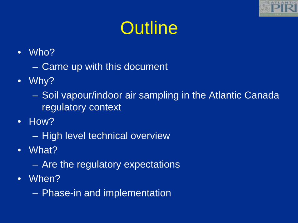
Outline• Who?
– Came up with this document• Why?
– Soil vapour/indoor air sampling in the Atlantic Canada regulatory context
• How?– High level technical overview
• What?– Are the regulatory expectations
• When?– Phase-in and implementation

Who?
PIRI Task Group Participants
• Co-ordinator– PIRI committee representative
• Participants– Technical expertise from across Canada– Local knowledge from Atlantic consultants
• Reviewed by PIRI Committee

Why?
Atlantic RBCA History
• 1999 – Atlantic RBCA software V.1
• 2003 – Atlantic RBCA software V.2– Harmonizes with Canada-Wide Standard for
Petroleum Hydrocarbons in Soil released in December 2000.
– New Atlantic PIRI User Guidance– New Tier I Lookup Tables
Atlantic Provincial Uniformity• Atlantic PIRI process provided:
• Uniformity of remedial criteria (level playing field)• Shared technical resources• Common site assessment protocol• Common laboratory methods• Common human health risk assessment method• Common computer model tool• Common screening for ecological receptors
• Now a common guideline for direct assessment of the indoor air pathway
Atlantic RBCA Tiered Approach
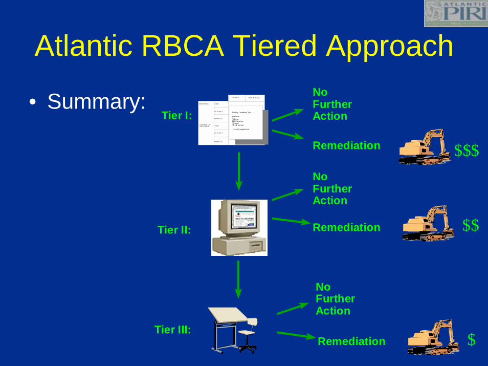
• Summary:Tier I:
Tier II:
RESIDENTIA L SAND
CLAY /SILT
BEDRO CK
COMM ERCIAL/IND USTRIAL SAND
CLAY /SILT
BEDRO CK
Lookup “numbers” f or....
BenzeneTol ueneEt hyl benzeneXylenesTP H F ract ion
....would appear here.
POTABLE NON -PO TA BLE
NoFurtherAction
Remediation $$$NoFurtherAction
Remediation $$
Tier III:Remediation $
NoFurtherAction

Atlantic Regulatory ProcessesNotification
Emergency Response
Tier I
Tier II
Tier III
Corrective Action
Monitoring
Site Closure
Site Assessment
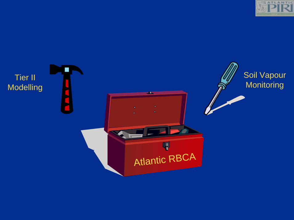
Atlantic RBCA
Soil VapourMonitoring
Tier IIModelling

How?Soil Vapour
Sampling
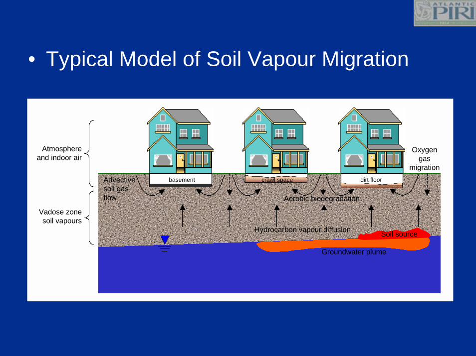
• Typical Model of Soil Vapour Migration
basement crawl space dirt floor
Hydrocarbon vapour diffusion
Groundwater plume
Soil source
Advectivesoil gasflow
Atmosphereand indoor air
Vadose zonesoil vapours
Oxygengas
migration
Aerobic biodegradation
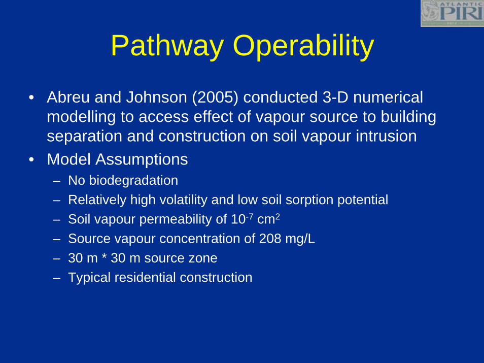
Pathway Operability• Abreu and Johnson (2005) conducted 3-D numerical
modelling to access effect of vapour source to building separation and construction on soil vapour intrusion
• Model Assumptions– No biodegradation– Relatively high volatility and low soil sorption potential– Soil vapour permeability of 10-7 cm2
– Source vapour concentration of 208 mg/L– 30 m * 30 m source zone– Typical residential construction
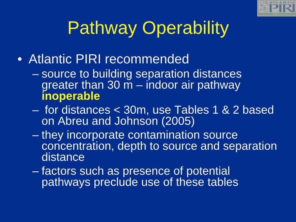
Pathway Operability• Atlantic PIRI recommended
– source to building separation distances greater than 30 m – indoor air pathway inoperable
– for distances < 30m, use Tables 1 & 2 based on Abreu and Johnson (2005)
– they incorporate contamination source concentration, depth to source and separation distance
– factors such as presence of potential pathways preclude use of these tables
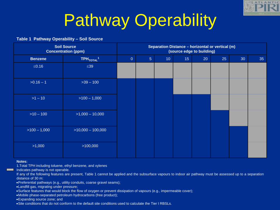
Pathway Operability
Notes:1.Total TPH including toluene, ethyl benzene, and xylenesIndicates pathway is not operable.If any of the following features are present, Table 1 cannot be applied and the subsurface vapours to indoor air pathway must be assessed up to a separation distance of 30 m:•Preferential pathways (e.g., utility conduits, coarse gravel seams);•Landfill gas, migrating under pressure;•Surface features that would block the flow of oxygen or prevent dissipation of vapours (e.g., impermeable cover); •Mobile phase-separated petroleum hydrocarbons (free product);•Expanding source zone; and•Site conditions that do not conform to the default site conditions used to calculate the Tier I RBSLs.
>100,000>1,000
>10,000 – 100,000>100 – 1,000
>1,000 – 10,000>10 – 100
>100 – 1,000>1 – 10
>39 – 100>0.16 – 1
≤39≤0.16
35302520151050TPHTOTAL1Benzene
Separation Distance – horizontal or vertical (m)(source edge to building)
Soil SourceConcentration (ppm)
Table 1 Pathway Operability – Soil Source
Site Characterization
• Atlantic PIRI “Minimum Site Assessment Requirements”
• Adequate site characterization and delineation of impacts to Tier I RBSLs, regardless of property lines, is a fundamental requirement of the PIRI process and is the basis for sound decision making on contaminated site management. Any approach using soil vapour or indoor air sampling should not reduce or eliminate this basic requirement.
Site Characterization
•Size, location, and type.•A description of construction features including age, basement or slab on grade, foundation cracks, sumps.•A description of heating systems (e.g., forced air furnaces, baseboard heaters).•A description of mechanical systems (e.g., HVAC) and appliances.
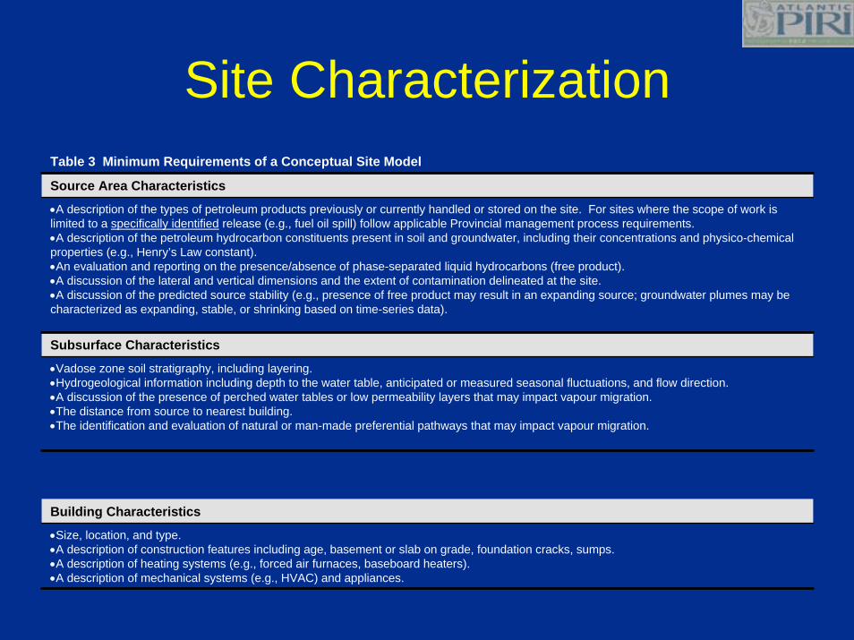
Building Characteristics
•Vadose zone soil stratigraphy, including layering.•Hydrogeological information including depth to the water table, anticipated or measured seasonal fluctuations, and flow direction.•A discussion of the presence of perched water tables or low permeability layers that may impact vapour migration.•The distance from source to nearest building.•The identification and evaluation of natural or man-made preferential pathways that may impact vapour migration.
Subsurface Characteristics
•A description of the types of petroleum products previously or currently handled or stored on the site. For sites where the scope of work is limited to a specifically identified release (e.g., fuel oil spill) follow applicable Provincial management process requirements.•A description of the petroleum hydrocarbon constituents present in soil and groundwater, including their concentrations and physico-chemical properties (e.g., Henry’s Law constant).•An evaluation and reporting on the presence/absence of phase-separated liquid hydrocarbons (free product).•A discussion of the lateral and vertical dimensions and the extent of contamination delineated at the site.•A discussion of the predicted source stability (e.g., presence of free product may result in an expanding source; groundwater plumes may be characterized as expanding, stable, or shrinking based on time-series data).
Source Area Characteristics
Table 3 Minimum Requirements of a Conceptual Site Model
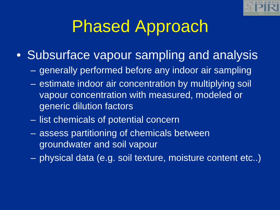
Phased Approach• Subsurface vapour sampling and analysis
– generally performed before any indoor air sampling– estimate indoor air concentration by multiplying soil
vapour concentration with measured, modeled or generic dilution factors
– list chemicals of potential concern– assess partitioning of chemicals between
groundwater and soil vapour– physical data (e.g. soil texture, moisture content etc..)

Phased Approach• Sub-Slab Monitoring
– Design Considerations• Sub-slab soil gas sampling relatively simple• Accomplished with an electric hammer-drill,
avoiding the need for a more-costly drilling rig– Drawbacks
• Need access agreement with building owner• Intrusive, disruptive or unpleasant for property
owners– U.S.EPA(2004) recommends 3 samples for a
building the size of a typical domestic residence
Phased Approach
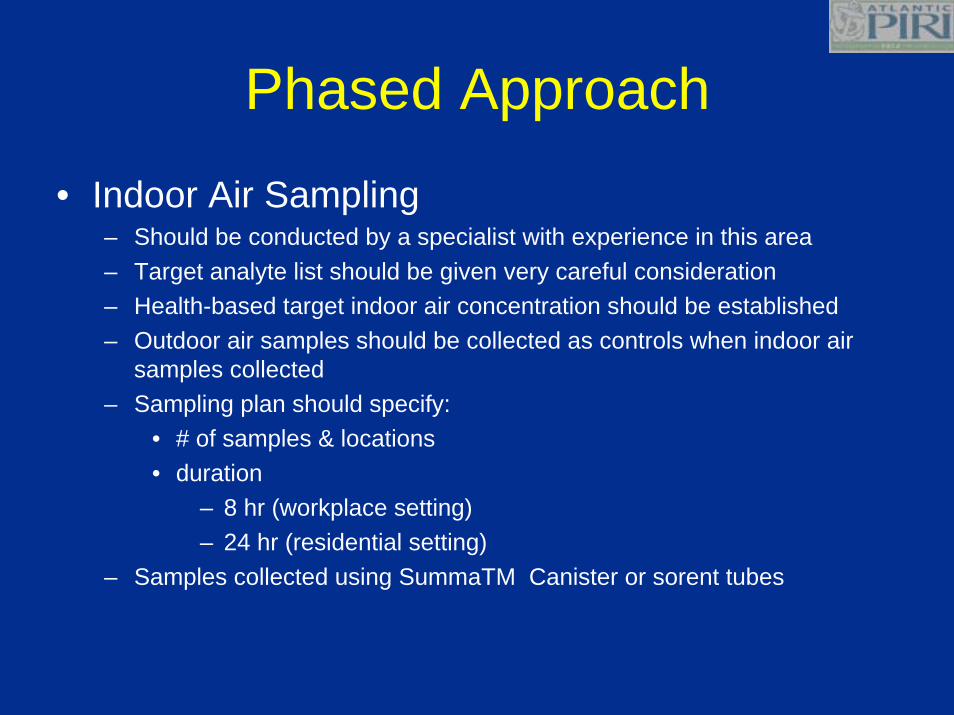
• Indoor Air Sampling– Should be conducted by a specialist with experience in this area– Target analyte list should be given very careful consideration– Health-based target indoor air concentration should be established– Outdoor air samples should be collected as controls when indoor air
samples collected– Sampling plan should specify:
• # of samples & locations• duration
– 8 hr (workplace setting)– 24 hr (residential setting)
– Samples collected using SummaTM Canister or sorent tubes

Pathway potentially operable?- Tables 1 and 2
Tier I/II assessment- Tier I/II applicable?
- Concentrations < RBSLs/SSTLs?
Measure source vapour concentrations- Concentrations < RfCs, RSCs?
Dilution factors applicable?
Predict indoor air concentrations- Concentrations > RfCs, RSCs?
Closure monitoring
Incompletepathway
Applydilution factor
of 100*
Further assesssubsurface vapour
concentrations closerto building
Measure sub-slabor indoor air concentrations
- refer to Figure 3
Y
Y
Y
N
N
Y
N
N
Y
Y
N
Contamination or water table<1m below foundation?
Y
N
Figure 2 Soil Vapour Sampling Approach
Emergency action required?
Adequate site characterization?- Tier I delineation
Implementmitigative action
Y
N
N
Site closure
Y
* Refer to Section 6.2 for rationalefor dilution factor.
RfC - Reference ConcentrationRSC - Risk Specific Concentration
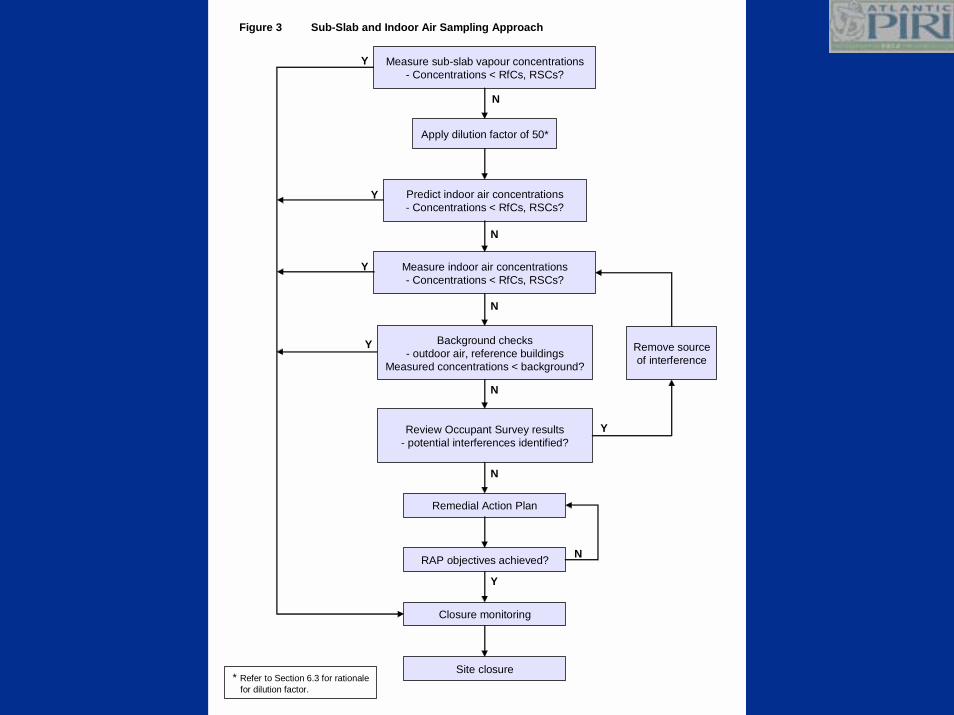
Predict indoor air concentrations- Concentrations < RfCs, RSCs?
Closure monitoring
Remove sourceof interference
Background checks- outdoor air, reference buildings
Measured concentrations < background?
Y
Y
Y
Y
Y
N
N
Measure indoor air concentrations- Concentrations < RfCs, RSCs?
Review Occupant Survey results- potential interferences identified?
Remedial Action Plan
RAP objectives achieved?
N
N
N
Figure 3 Sub-Slab and Indoor Air Sampling Approach
Measure sub-slab vapour concentrations- Concentrations < RfCs, RSCs?
Apply dilution factor of 50*
Y
N
Site closure* Refer to Section 6.3 for rationale
for dilution factor.
Specific Technical Issues
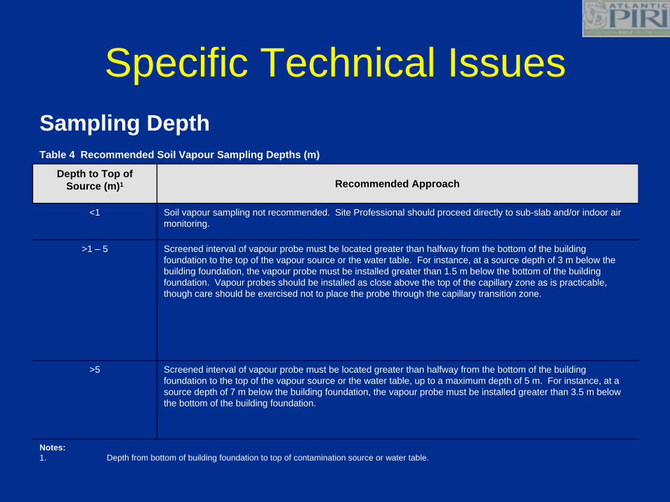
Notes:1. Depth from bottom of building foundation to top of contamination source or water table.
Screened interval of vapour probe must be located greater than halfway from the bottom of the building foundation to the top of the vapour source or the water table, up to a maximum depth of 5 m. For instance, at a source depth of 7 m below the building foundation, the vapour probe must be installed greater than 3.5 m below the bottom of the building foundation.
>5
Screened interval of vapour probe must be located greater than halfway from the bottom of the building foundation to the top of the vapour source or the water table. For instance, at a source depth of 3 m below the building foundation, the vapour probe must be installed greater than 1.5 m below the bottom of the building foundation. Vapour probes should be installed as close above the top of the capillary zone as is practicable, though care should be exercised not to place the probe through the capillary transition zone.
>1 – 5
Soil vapour sampling not recommended. Site Professional should proceed directly to sub-slab and/or indoor air monitoring.
<1
Recommended ApproachDepth to Top of
Source (m)1
Sampling DepthTable 4 Recommended Soil Vapour Sampling Depths (m)
Specific Technical Issues
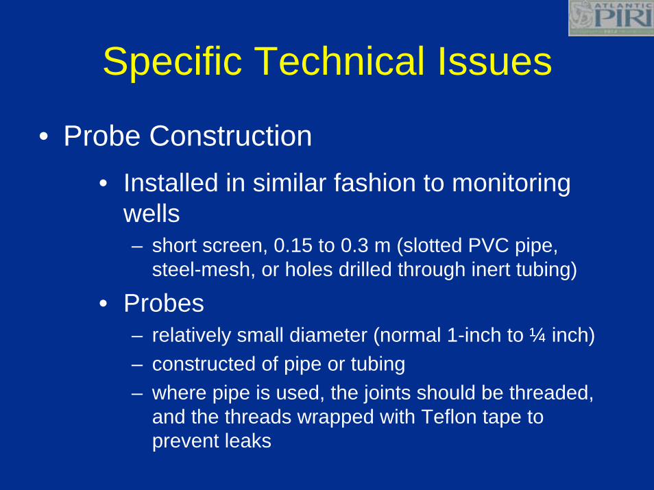
• Probe Construction• Installed in similar fashion to monitoring
wells– short screen, 0.15 to 0.3 m (slotted PVC pipe,
steel-mesh, or holes drilled through inert tubing)
• Probes– relatively small diameter (normal 1-inch to ¼ inch)– constructed of pipe or tubing– where pipe is used, the joints should be threaded,
and the threads wrapped with Teflon tape to prevent leaks

Specific Technical Issues
• Probe Construction• Coarse sand or fine gravel placed
surrounding screened portion of probe and bentonite seal constructed above screened portion of probe
• Remainder of borehole annulus filled with a slurry powdered bentonite and water
• Top soil gas probe with air-tight valve and protective casing

Specific Technical Issues
• Purging• Recommended Purging Procedure:
– Calculate dead volume based on the inner volume of the probe and sample tubing
– Purge probe using a flow rate maintaining a vacuum less than 10” H20
– Purge between 3 to 5 casing plus sample tubing volumes
• Smaller sample volumes provide better resolution, but more spatial variability
• Larger sample volumes provide more integrated average concentration
Specific Technical Issues
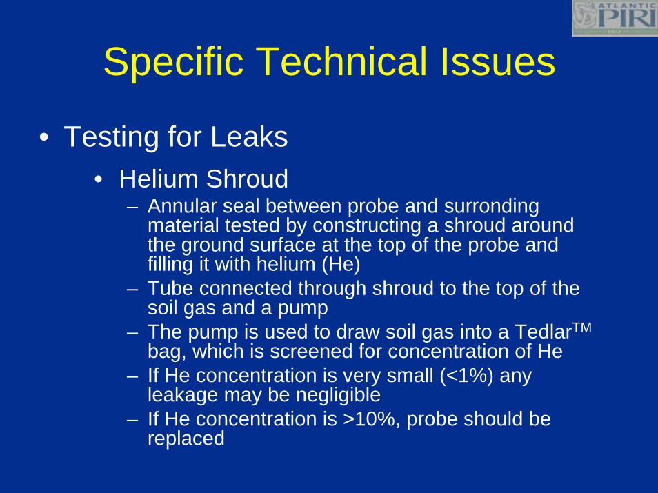
• Testing for Leaks• Helium Shroud
– Annular seal between probe and surrondingmaterial tested by constructing a shroud around the ground surface at the top of the probe and filling it with helium (He)
– Tube connected through shroud to the top of the soil gas and a pump
– The pump is used to draw soil gas into a TedlarTM
bag, which is screened for concentration of He– If He concentration is very small (<1%) any
leakage may be negligible– If He concentration is >10%, probe should be
replaced

Specific Technical Issues
• Helium Shroud
Reference: http://www.health.state.ny.us/nysdoh/gas/svi_guidance/training/docs/svi_investigation.pdf
Specific Technical Issues
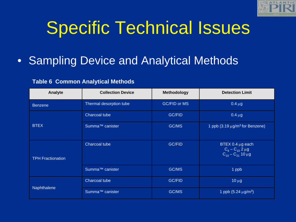
• Sampling Device and Analytical Methods
1 ppb (5.24 µg/m3)GC/MSSumma™ canister
10 µgGC/FIDCharcoal tube
Naphthalene
1 ppbGC/MSSumma™ canister
BTEX 0.4 µg eachC6 – C10 2 µg
C10 – C21 10 µg
GC/FIDCharcoal tube
TPH Fractionation
1 ppb (3.19 µg/m3 for Benzene)GC/MSSumma™ canister
0.4 µgGC/FIDCharcoal tube
BTEX
0.4 µgGC/FID or MSThermal desorption tubeBenzene
Detection LimitMethodologyCollection DeviceAnalyte
Table 6 Common Analytical Methods
Interpretation
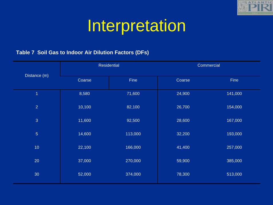
513,00078,300374,00052,00030
385,00059,900270,00037,00020
257,00041,400166,00022,10010
193,00032,200113,00014,6005
167,00028,60092,50011,6003
154,00026,70082,10010,1002
141,00024,90071,6008,5801
FineCoarseFineCoarse
CommercialResidential
Distance (m)
Table 7 Soil Gas to Indoor Air Dilution Factors (DFs)
Interpretation• Alternative Dilution Factor (DF) required
for non-default site conditions• DF for soil vapours to indoor air range
from 100 to 10,000• 100 recommended as conservative value
for soil vapours (collected from >1m below building foundations) to indoor air
• DF of 50 is recommended for sub-slab vapours (<1m below building foundations) to indoor air
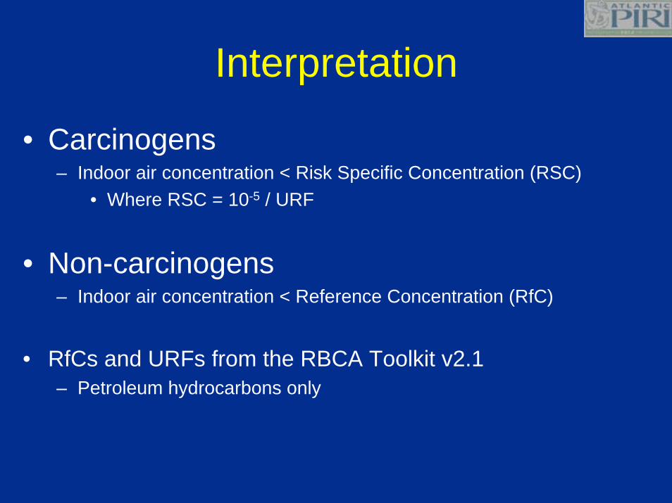
Interpretation
• Carcinogens– Indoor air concentration < Risk Specific Concentration (RSC)
• Where RSC = 10-5 / URF
• Non-carcinogens– Indoor air concentration < Reference Concentration (RfC)
• RfCs and URFs from the RBCA Toolkit v2.1– Petroleum hydrocarbons only

What?
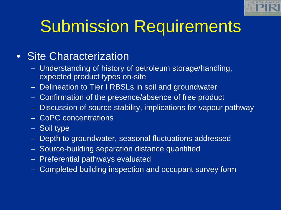
Submission Requirements• Site Characterization
– Understanding of history of petroleum storage/handling, expected product types on-site
– Delineation to Tier I RBSLs in soil and groundwater– Confirmation of the presence/absence of free product– Discussion of source stability, implications for vapour pathway– CoPC concentrations– Soil type– Depth to groundwater, seasonal fluctuations addressed– Source-building separation distance quantified– Preferential pathways evaluated– Completed building inspection and occupant survey form
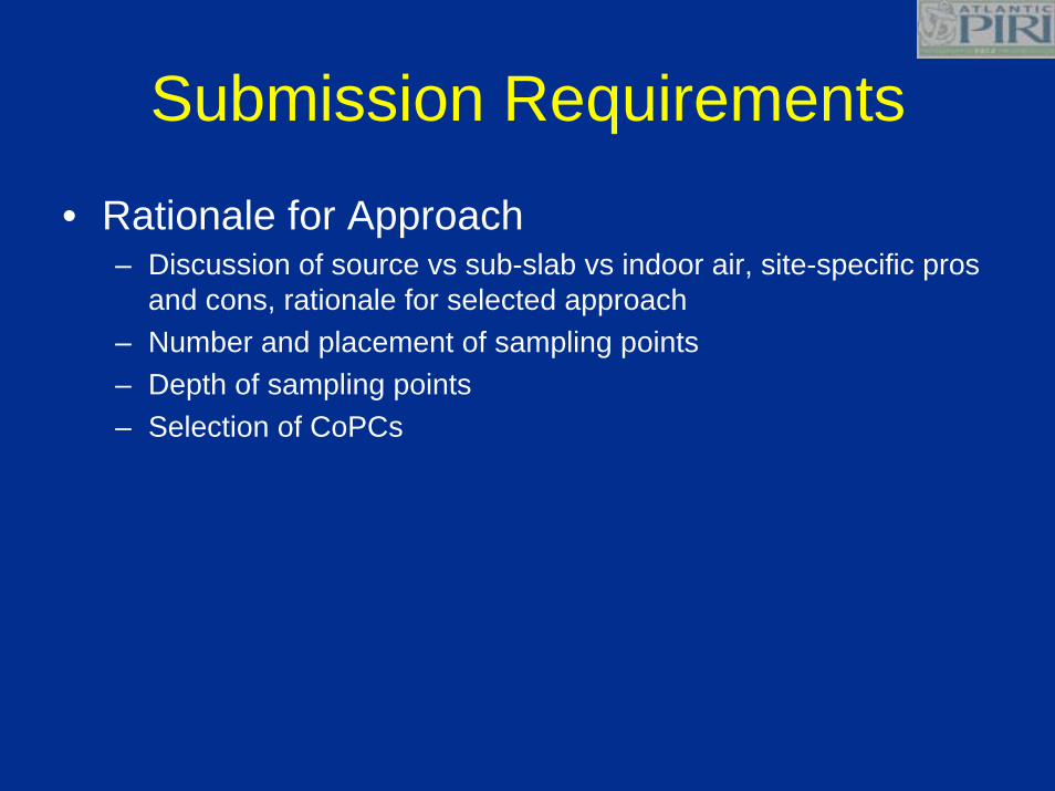
Submission Requirements
• Rationale for Approach– Discussion of source vs sub-slab vs indoor air, site-specific pros
and cons, rationale for selected approach– Number and placement of sampling points– Depth of sampling points– Selection of CoPCs
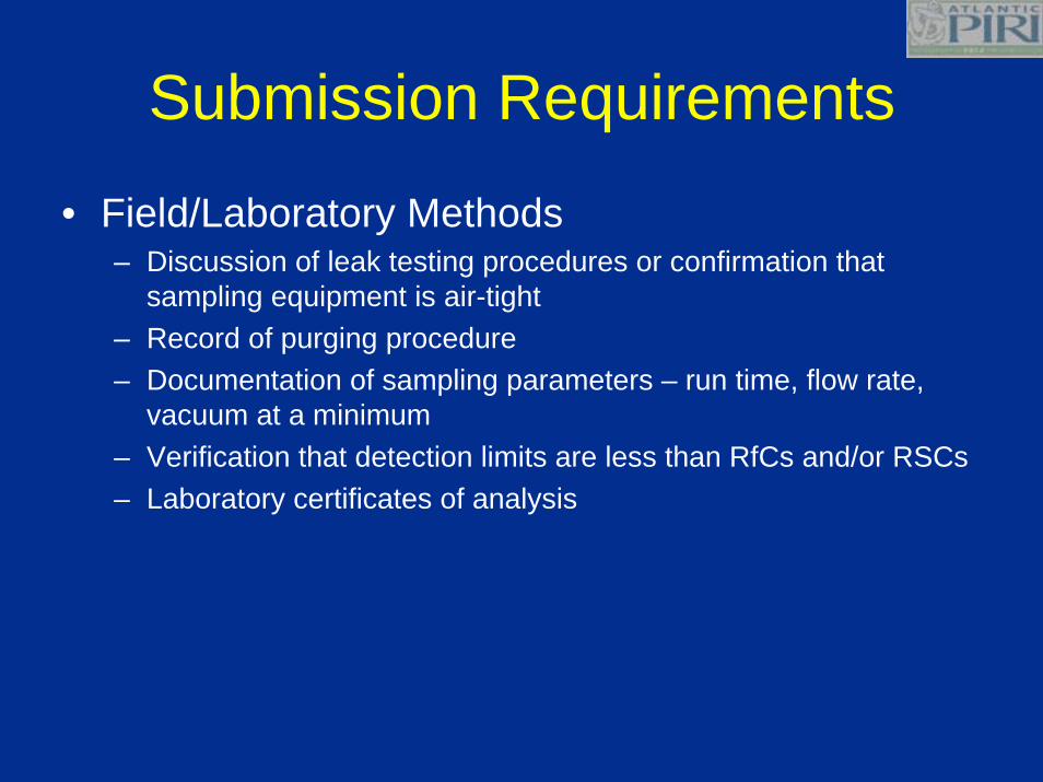
Submission Requirements
• Field/Laboratory Methods– Discussion of leak testing procedures or confirmation that
sampling equipment is air-tight– Record of purging procedure– Documentation of sampling parameters – run time, flow rate,
vacuum at a minimum– Verification that detection limits are less than RfCs and/or RSCs– Laboratory certificates of analysis
Submission Requirements
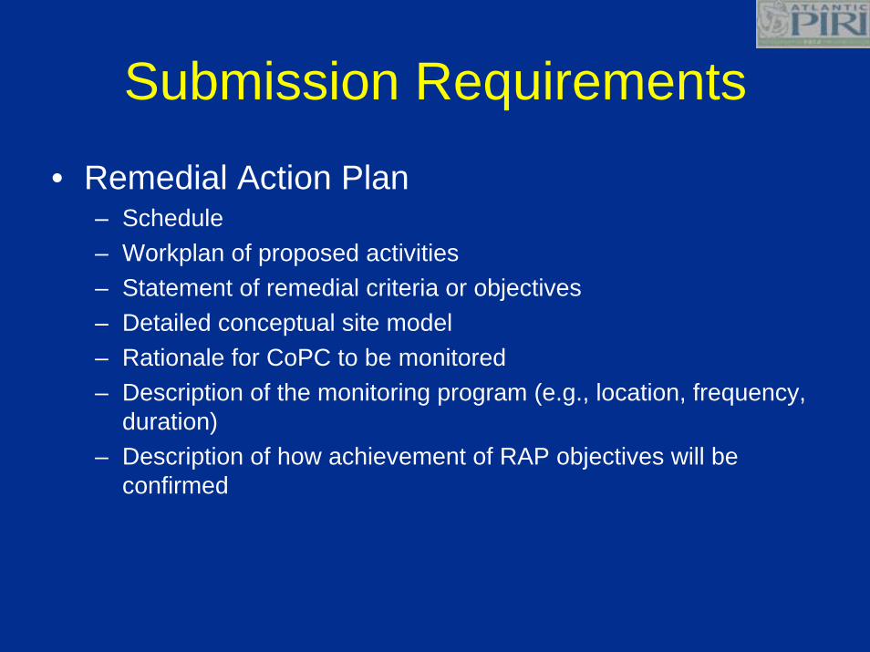
• Remedial Action Plan– Schedule– Workplan of proposed activities– Statement of remedial criteria or objectives– Detailed conceptual site model– Rationale for CoPC to be monitored– Description of the monitoring program (e.g., location, frequency,
duration)– Description of how achievement of RAP objectives will be
confirmed
Submission Requirements
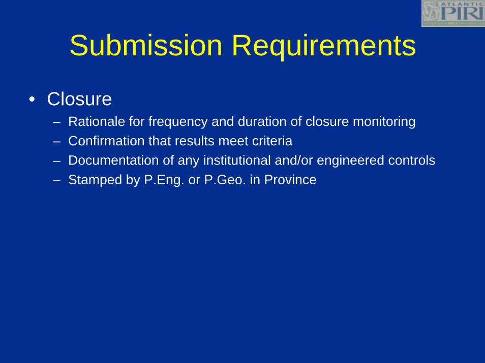
• Closure– Rationale for frequency and duration of closure monitoring– Confirmation that results meet criteria– Documentation of any institutional and/or engineered controls– Stamped by P.Eng. or P.Geo. in Province

When?
Transition Period
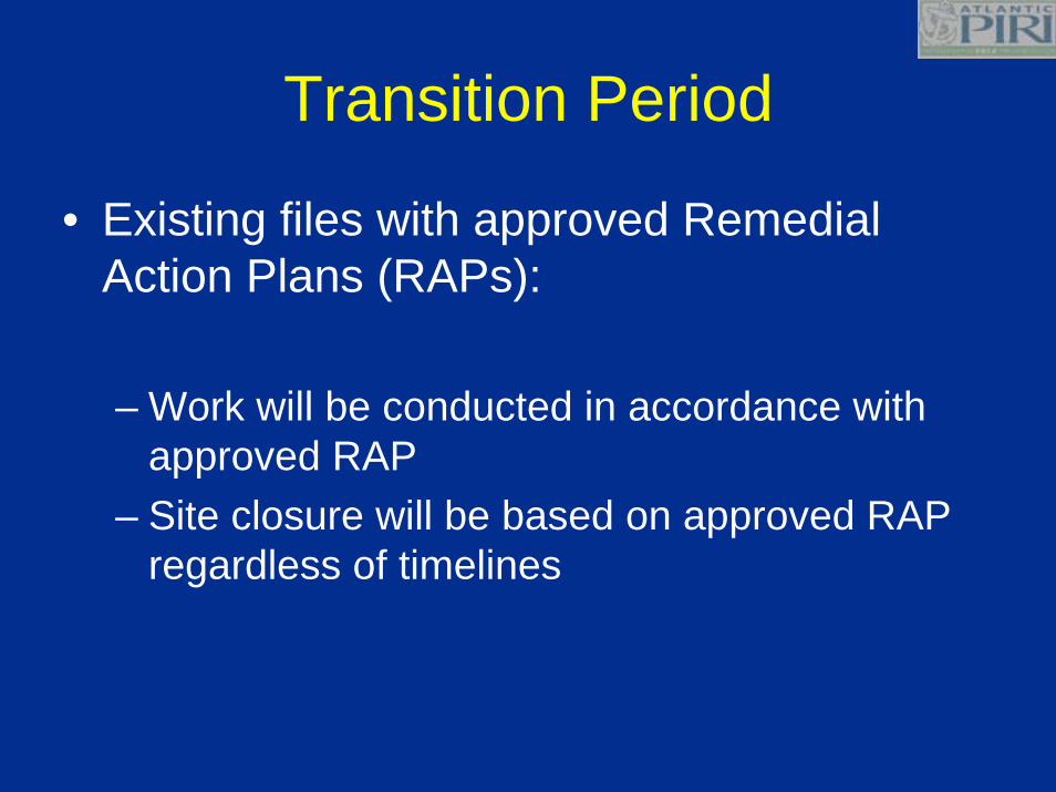
• Existing files with approved Remedial Action Plans (RAPs):
– Work will be conducted in accordance with approved RAP
– Site closure will be based on approved RAP regardless of timelines
Transition Period
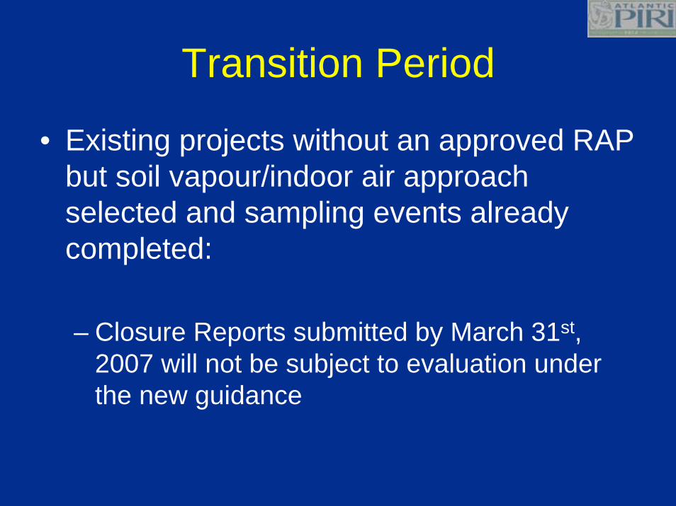
• Existing projects without an approved RAP but soil vapour/indoor air approach selected and sampling events already completed:
– Closure Reports submitted by March 31st, 2007 will not be subject to evaluation under the new guidance

Transition Period
• Sites at the site characterization phase or remedial planning stage, no sampling events conducted:
– Subject to new guidance
Resources• American Petroleum Institute (API), 2005.
– Collecting and Interpreting Soil Gas Samples from the Vadose Zone: A Practical Strategy for Assessing the Subsurface Vapour-to-Indoor-Air Migration Pathway at Petroleum Hydrocarbon Sites. Publication No. 4741.
• Golder Associates, 2004.– Soil Vapour Intrusion Guidance for Health Canada Screening Level
Risk Assessment (SLRA). Prepared for Health Canada. Final Draft,November, 2004.
• United States Environmental Protection Agency (US EPA), 2002.– OSWER Draft Guidance for Evaluating the Vapor Intrusion to Indoor
Air Pathway From Groundwater and Soils (Subsurface Vapour Intrusion Guidance). http://www.epa.gov/epaoswer/hazwaste/ca/eis/vapor.htm