Embed Size (px)
Citation preview
GUIDANCE DOCUMENT FOR THE DESIGN OF RAPID INFILTRATION BASINS
Technical Publication WTS-3A
Nevada Division of Environmental Protection Bureau of Water Pollution Control
Technical Services Branch
Revised 2017
P a g e 2 | 13
Purpose and Scope of this Document The purpose of this guidance document is to assist the Nevada Division of Environmental Protection’s (NDEP) Bureau of Water Pollution Control (BWPC) and consulting technical staff (engineers, soil scientists, and geologists) in the design, permitting and operation of Rapid Infiltration Basins (RIBs) that discharge treated effluent into the subsurface. This document presents discussions on the various technical requirements, and provides an overview of what is required to obtain a BWPC permit to construct RIBs.
Acknowledgments BWPC would like to acknowledge the use of the guidance concerning RIBS from the Minnesota Pollution Control Agency in developing this document.
Rapid Infiltration Basins
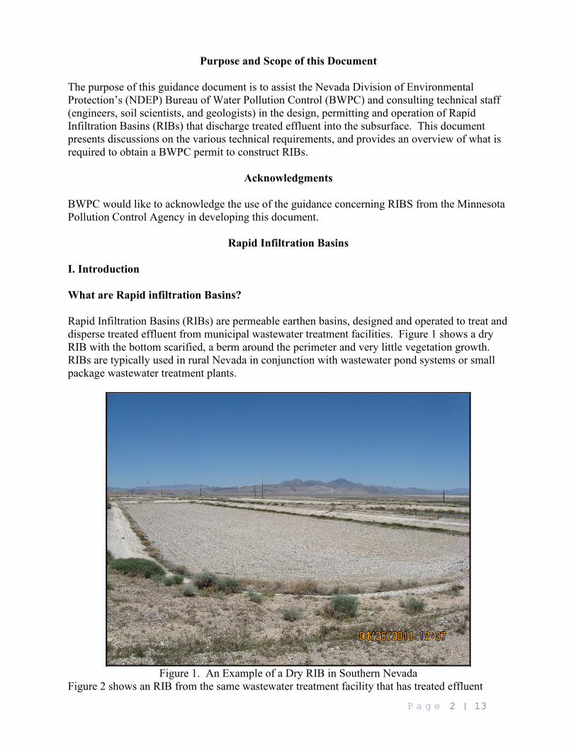
I. Introduction What are Rapid infiltration Basins? Rapid Infiltration Basins (RIBs) are permeable earthen basins, designed and operated to treat and disperse treated effluent from municipal wastewater treatment facilities. Figure 1 shows a dry RIB with the bottom scarified, a berm around the perimeter and very little vegetation growth. RIBs are typically used in rural Nevada in conjunction with wastewater pond systems or small package wastewater treatment plants.
Figure 1. An Example of a Dry RIB in Southern Nevada Figure 2 shows an RIB from the same wastewater treatment facility that has treated effluent
P a g e 3 | 13
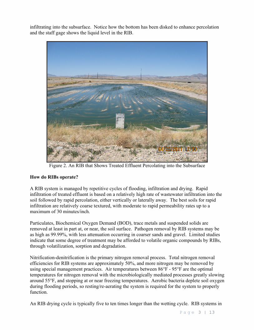
infiltrating into the subsurface. Notice how the bottom has been disked to enhance percolation and the staff gage shows the liquid level in the RIB.
Figure 2. An RIB that Shows Treated Effluent Percolating into the Subsurface
How do RIBs operate? A RIB system is managed by repetitive cycles of flooding, infiltration and drying. Rapid infiltration of treated effluent is based on a relatively high rate of wastewater infiltration into the soil followed by rapid percolation, either vertically or laterally away. The best soils for rapid infiltration are relatively coarse textured, with moderate to rapid permeability rates up to a maximum of 30 minutes/inch. Particulates, Biochemical Oxygen Demand (BOD), trace metals and suspended solids are removed at least in part at, or near, the soil surface. Pathogen removal by RIB systems may be as high as 99.99%, with less attenuation occurring in coarser sands and gravel. Limited studies indicate that some degree of treatment may be afforded to volatile organic compounds by RIBs, through volatilization, sorption and degradation. Nitrification-denitrification is the primary nitrogen removal process. Total nitrogen removal efficiencies for RIB systems are approximately 50%, and more nitrogen may be removed by using special management practices. Air temperatures between 86°F - 95°F are the optimal temperatures for nitrogen removal with the microbiologically mediated processes greatly slowing around 55°F, and stopping at or near freezing temperatures. Aerobic bacteria deplete soil oxygen during flooding periods, so resting/re-aerating the system is required for the system to properly function. An RIB drying cycle is typically five to ten times longer than the wetting cycle. RIB systems in
P a g e 4 | 13
northern Nevada are still able to operate in the winter even though there may be an ice layer on the surface of the RIBs. The nitrogen removal efficiency will be less during these cold months. These criteria need to be considered when proposing RIB hydraulic loading rates. II. Nitrogen Management Although there are several constituents of concern in wastewater, one of the main constituents of concern that influences RIB system design is nitrate-nitrogen. The engineer/consultant must design new RIB systems that provide nitrogen treatment. Nevada’s groundwater discharge permits contain the following language: “If the Total Nitrogen as N level increases in the groundwater to 7.0 mg/L, an alternate method of disposal shall be selected. If the increase is due to irrigation reuse, the Effluent Management Plan (EMP) shall be revised to provide management practices which increase the nitrogen uptake by vegetation and/or adjust other nitrogen sources such as fertilizer application rates. If the Total Nitrogen as N level in the groundwater increases to 9.0 mg/L, construction of an NDEP- approved alternate disposal site shall begin. When these levels are reached, the Permittee shall take all corrective action necessary to ensure that there is no further degradation to groundwater. If the Total Nitrogen as N level increases to 10.0 mg/L, discharge to groundwater must cease.” If the effluent going to the RIBs (verified by on-going effluent monitoring) contains a maximum of 10 mg/L total nitrogen (Total N), there must be a minimum 200-foot separation between the RIBs and the nearest surface water or potable water supply well. If the conditions described above cannot be met then a complete hydrogeologic investigation and groundwater monitoring plan will be required. If the hydrogeologic evaluation demonstrates little potential for ground water impacts (e.g., the RIBs are not located near water supply wells etc.) then a limit of 10 mg/L for Total Nitrogen will be assigned to down-gradient monitoring wells. If the hydrogeologic evaluation determines that the groundwater has the potential for being impacted by the RIBs then a limit of 10 mg/L of Total Nitrogen will be assigned to down-gradient monitoring wells. To reflect ambient conditions where existing groundwater Total N concentrations are already elevated, Total N limits will be set at the mean of a minimum of three up-gradient groundwater samples. Several nitrogen reduction methods may be employed at sites with elevated nitrogen levels to reduce groundwater impacts from RIBs. Nitrogen reduction methods include:
1. Initially locating the system where natural soil and/or ground water conditions promote denitrification (anoxic and reducing conditions with some dissolved organic carbon);
2. The RIBs being located as far up-gradient from surface waters and drinking water wells as possible, with the down-gradient property maintained as green space;
3. The RIBs designed as long as practical and perpendicular to the groundwater contour; 4. Installation of down-gradient recovery wells for non-potable (E.G. irrigation) use; 5. Selecting loading and resting cycles that promote denitrification; and
III. Preliminary RIB Design Suitable Locations
P a g e 5 | 13
By locating an RIB system on a relatively level site with deep, uniform, unsaturated moderately permeable soils, a deep water table, and is adjacent to a ground water discharge area should increase the performance of the system and reduce associated environmental impacts. Areas with steep slopes, shallow water tables, adjacent to wetlands, or are in soils that are too coarse or too fine may make siting RIBs more difficult, or may reduce the performance of the RIB system. Unsuitable Locations Systems that are located within wellhead protection areas, in areas with shallow bedrock, above sole-source aquifers, or on a flood plain are not the most desirable sites for RIB systems. It is recommended that RIBs be located outside of the 1,000-foot Drinking Water Protection Area (DWPA) or a state-endorsed Wellhead Protection Area with a minimum 2-year time of travel, whichever is greater. Topographic Maps A site map of the proposed RIB site shall be submitted to BWPC for its review and approval. The site map must show the surface topography, with two-foot elevation contour intervals, adjacent water courses, and distances to wells within 1 mile from the proposed RIBs. By regulation, RIBs cannot be closer than 200 feet from a public drinking water well (NAC 278.460). Number of RIBs The RIB systems should have a minimum of two (2) basins. The number of basins can vary depending on whether continuous wastewater discharge is required. Individual basin size can range from 0.5-5 acres for small to medium-sized systems, and up to 5-20 acres for larger systems. EPA has guidance on the number of basins needed, based on the projected number and duration of loading and resting cycles. Dimensions To maximize land use, RIBs should be square or rectangular in shape and adjacent to each other. Long, narrow basins with their length perpendicular to groundwater flow direction may reduce groundwater mounding. The engineer or consultant designing the RIB system must evaluate the potential that basins will cause unacceptable mounding in adjacent basins during system design. Freeboard Each RIB needs to have freeboard built into the design to prevent overtopping from waves generated by wind action. For ponds one acre or less, two feet of freeboard is sufficient. Any RIB larger than one acre must have at least three feet of freeboard. Erosion Control RIBs must be protected from erosion both during and after construction to keep fines from
P a g e 6 | 13
washing in and reducing basin infiltration. Monitoring Wells If monitoring wells are required by the discharge permit, there must be one up-gradient and two down-gradient monitoring wells that are part of the RIB system. The down-gradient monitoring wells shall be located in the most probable pathway of the groundwater flow and no further than 250-feet from the edge of the RIBs. The up-gradient monitoring well is used to provide background water quality information and it must be located in the pathway of groundwater flow. Fencing and Signage A six-foot chain-link fence shall be installed around the perimeter of the RIBs with a sign installed at least every 500-feet on, or adjacent to, the fencing. If the length of the fence is less than 500-feet, then a sign is required on each outside corner of the fence. IV. Requirements for Site Suitability, Soils, and Hydrogeologic Site Investigation Prior to submitting the plans to BWPC for the RIB system, the Permittee must undertake a Site Suitability Investigation and a Soils Investigation. Soils are critical for the treatment process. The Soil Investigation Report (SIR) must be prepared by a qualified person. The SIR must address the following items:
1. When designing the RIBs a minimum of five feet of soil must exist between the bottom of the RIBs and the actual ground water mound height (including the capillary fringe);
2. For systems where mounding may be an issue (based on the mounding analyses) piezometers must be installed, and on-going measurements must be made in the piezometers to ensure that at minimum five feet of separation is maintained during operation;
3. If a hydraulic connection of the percolating effluent with waters of the U.S. is identified, BWPC must be notified prior to submittal of the application;
4. The soil must be classified to a depth of 10-feet below the bottom of the RIBs. Evidence demonstrating that excessive mounding will not occur below the RIB shall be shown;
5. Borehole lithology (physical and chemical characteristics) of the vadose zone to a depth of 150-feet or to the top of the groundwater table. The depth to an impermeable layer below the basin bottom of less than 40-feet will not be allowed for an RIB unless a mounding analysis shows this to be acceptable for disposal. (An impermeable layer is defined as strata of 3-inches or greater thickness with a minimum permeability of 0.014 in/hr (1.0 X 10⁻⁵ cm/sec);
6. A summary of the existing groundwater quality, flow gradients, and flux. 7. Infiltration and permeability tests results. The soils shall be tested at the bottom of the
RIB, and five feet below the bottom of the basin. If geologic soils data shows discontinuous layering, then tests shall be performed at multiple sites. The tests shall be conducted in-situ or on undisturbed samples. A flooding basin test or approved equal shall be used for the surface bottom test;
8. If the treated effluent is high in solids, then an appropriate high solids fluid shall be used
P a g e 7 | 13
to conduct these tests. Percolate mounding shall be considered excessive if it remains within 10-feet of the basin bottom during the drying cycle. At a minimum, the basin bottom permeability to a depth of 12-inches cannot be less than 2.0 in/hr (1.4 cm/sec).
V. Determining Hydraulic Loading Rates The sequence for determining annual and individual hydraulic loading rates for RIB systems is as follows:
1. Adequately characterize the site soils; 2. Estimate annual and daily loading rates; and 3. Verify the estimations with empirically-derived (actual) basin-by-basin flooding tests
after the basins are constructed. Hydraulic loading rates are estimated primarily on soil texture, consistence and structure of the most hydraulically limiting soil horizon above the seasonal high water table. A combination of these three soil properties will determine the most limiting soil horizon, and infiltration rates below the system.
Laboratory sieve and permeability measurements, and/or preferably in-situ measurements using a double ring infiltrometer or equivalent method of the most transmissive (i.e. quantity) and the most hydraulically limiting (MHL) horizons especially on less favorable sites should be undertaken for estimating hydraulic loading rates. When working with RIBs the terms vertical hydraulic conductivity (Kv), horizontal hydraulic conductivity (Kh) and saturated hydraulic conductivity (Ksat) are used. Kv is used to estimate the rate of flow of water into and through the soil, in other words a “soil acceptance rate.” Kh is used for mounding analysis. Mounding occurs when infiltrated wastewater (which is moving in a vertical direction) encounters the water table and cannot flow “away” from the application site fast enough. The direction of this saturated flow or subsurface drainage has to be in a lateral direction “away” from the application site. Therefore, some combination of Kv and Kh are used for mounding analysis. The further from the center of the mound, the more the groundwater is controlled by Kh. Ksat is a field-derived Kv. Ksat typically represents the fastest rate that clean water will move through the soil. Treated effluent infiltration rates are usually lower than the Ksat for clean water. Field-scale flooding basin tests (test areas at least 75 ft2 ) should also be considered for design purposes. This is because field-scale flooding measurements are typically more accurate than laboratory-derived permeabilities or double ring infiltrometer measurements for estimating hydraulic acceptance rates and ultimately system performance. The primary purpose of a flooding basin test is to define Kv. Basin flooding tests are conducted by flooding the basin(s) at an estimated rate, to determine a rate such that no standing water is present at the end of the loading period. The EPA has provided guidelines that should be used for conducting flooding basins tests. Depending on suspended and dissolved solids the performance of RIBs may decrease with time. The EPA’s allowable hydraulic loading rate (incorporating a safety factor) is approximately an order of magnitude less than the actual “effective” hydraulic conductivity. To expedite permit issuance, annual basin hydraulic loading limits will be set at ten (10) percent of the measured in-situ infiltration rates. Laboratory and in-situ measurements are only estimates of hydraulic performance. The final annual loading rates will be obtained by taking ten (10)
P a g e 8 | 13
percent of the effective infiltration rate(s) obtained by basin-by-basin flooding tests, conducted after the permit is issued and the RIBs are built. These final loading rates will be included in the revised final Operations and Maintenance (O&M) Manual that must be submitted for BWPC for its review and approval at the completion of the performance certification period (twelve months after initiation of operations). Individual loading cycle application rates (as opposed to annual rates) are usually set at less than 50 percent of the observed infiltration rate to allow for reduced infiltration caused by organic matter and solids in the wastewater. This should also be addressed in the O&M Manual. VI. Groundwater Mounding Accurate soils and hydrogeologic information is needed to estimate the RIB system’s performance. To reduce mounding and to provide maximum treatment, the long axes of the RIBs should be aligned perpendicular to groundwater flow direction. Therefore, the direction of groundwater flow should be determined in the areas proposed for the basins, prior to them being built. Hydraulic acceptance rates are not mounding calculations. Mounding calculations need to be determined based on hydraulic loading rates, aquifer thickness, K and K , and depth to the seasonal high water table to ensure that an adequate aerated treatment zone is maintained. According to EPA, the capillary fringe above groundwater mounds should never be closer than two feet to the bottom of the infiltration basin. This corresponds to a water table depth of about 3 to 7 feet, depending on soil texture. Under certain circumstances such as systems located in coarse soils with a deep water table a more formal mounding analyses may not be necessary. However, the closer the water table is to the base of the RIBs, the more variable the soils, the higher the proposed loading rates and the lower the K , the more important mounding calculations become and corresponding, the more conservative the assumptions used should be when making the calculations. The EPA estimation and the Finnemore and Hantzsche method are acceptable methods for estimating mounding (see bottom of Appendix II). Mounding calculations are estimates. Depending on the potential for mounding estimated from the mounding analyses piezometers will need to be installed between or immediately adjacent to the RIBs. An enforceable part of the discharge permit will state that even with mounding, the groundwater surface as measured in the piezometers will need to be kept 5 feet or lower than the bottom of the RIBs. Therefore the surveyed elevation(s) of the bottom of the RIBs need to be obtained for operational and comparative use later. During construction, marginal overlying soils may be carefully removed from the proposed RIB site(s) to expose less hydraulically restrictive horizons. Unfortunately by doing so, it may bring the base of the RIB closer to the acceptable three feet separation distance of the (mounded) water table. When constructing RIBs the equipment that is used must minimize soil compaction. VII. Operational Criteria Depending on site conditions and effluent strength loading and resting cycles may be selected to either maximize infiltration, or to maximize nitrogen removal. A regular drying period is necessary for system performance. To maximize infiltration the drying periods should be long
P a g e 9 | 13
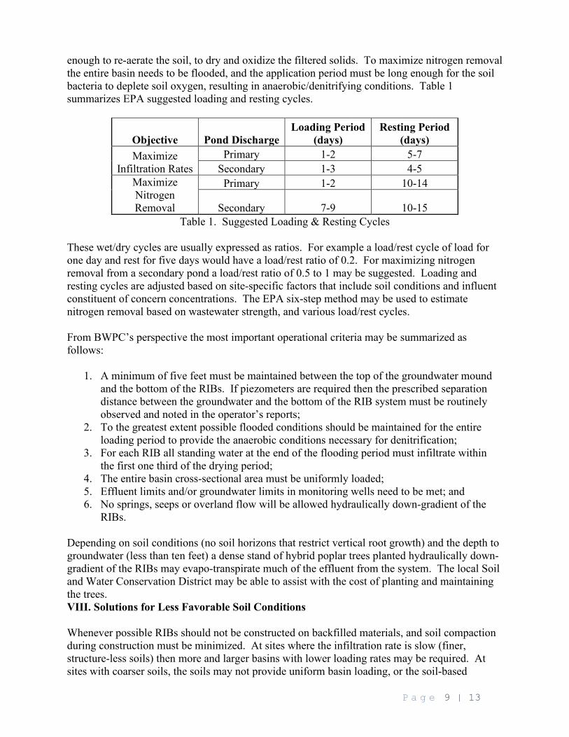
enough to re-aerate the soil, to dry and oxidize the filtered solids. To maximize nitrogen removal the entire basin needs to be flooded, and the application period must be long enough for the soil bacteria to deplete soil oxygen, resulting in anaerobic/denitrifying conditions. Table 1 summarizes EPA suggested loading and resting cycles.
Objective Pond Discharge Loading Period
(days) Resting Period
(days) Maximize
Infiltration Rates Primary 1-2 5-7
Secondary 1-3 4-5 Maximize Nitrogen Removal
Primary 1-2 10-14
Secondary 7-9 10-15 Table 1. Suggested Loading & Resting Cycles
These wet/dry cycles are usually expressed as ratios. For example a load/rest cycle of load for one day and rest for five days would have a load/rest ratio of 0.2. For maximizing nitrogen removal from a secondary pond a load/rest ratio of 0.5 to 1 may be suggested. Loading and resting cycles are adjusted based on site-specific factors that include soil conditions and influent constituent of concern concentrations. The EPA six-step method may be used to estimate nitrogen removal based on wastewater strength, and various load/rest cycles. From BWPC’s perspective the most important operational criteria may be summarized as follows:
1. A minimum of five feet must be maintained between the top of the groundwater mound and the bottom of the RIBs. If piezometers are required then the prescribed separation distance between the groundwater and the bottom of the RIB system must be routinely observed and noted in the operator’s reports;
2. To the greatest extent possible flooded conditions should be maintained for the entire loading period to provide the anaerobic conditions necessary for denitrification;
3. For each RIB all standing water at the end of the flooding period must infiltrate within the first one third of the drying period;
4. The entire basin cross-sectional area must be uniformly loaded; 5. Effluent limits and/or groundwater limits in monitoring wells need to be met; and 6. No springs, seeps or overland flow will be allowed hydraulically down-gradient of the
RIBs. Depending on soil conditions (no soil horizons that restrict vertical root growth) and the depth to groundwater (less than ten feet) a dense stand of hybrid poplar trees planted hydraulically down-gradient of the RIBs may evapo-transpirate much of the effluent from the system. The local Soil and Water Conservation District may be able to assist with the cost of planting and maintaining the trees. VIII. Solutions for Less Favorable Soil Conditions Whenever possible RIBs should not be constructed on backfilled materials, and soil compaction during construction must be minimized. At sites where the infiltration rate is slow (finer, structure-less soils) then more and larger basins with lower loading rates may be required. At sites with coarser soils, the soils may not provide uniform basin loading, or the soil-based
P a g e 10 | 13
treatment (aerobic/anaerobic conditions) necessary to protect groundwater. In EPA’s Process Design Manual, Supplement on Rapid Infiltration and Overland Flow, it states that in all cases it is necessary that uniform wastewater application must take place over the entire basin surface. In more coarse soils, to ensure uniform distribution the distribution system might range from a network of pipes and troughs to sprinklers in the extreme case. At RIB sites where the infiltration rate is too fast, several options may be considered including the following:
• Having smaller basins and multiple inlets; • Carefully removing and stockpiling approximately 12” of the basin soil and then blending
finer textured soils (silt, 5%-10%) into the stockpiled soil, and then placing this reworked soil on top of a geotextile material laid out in the basins;
• Placing a geotextile material that sufficiently slows down infiltration directly on top of the RIBs (possibly using sandbags as anchors), and then placing 12-inches of clean sand on top of the reduced hydraulic conductivity geotextile material;
• Installing a (very) level matrix of troughs made of concrete or pipe cut lengthwise that is installed and kept level so uniform distribution within the RIBs is maintained. A part of the Operations and Maintenance (O&M) Plan will require that the operator must routinely observe drainage, and re-level the drainage channels as necessary;
• Installing a matrix of pressure-distributed distribution lines (i.e. drain tile) with the orifices sized and positioned optimally (sideways or upright) so as to ensure uniform loading and reduced basin scouring;
• Spraying into the basins using a fixed set (overhead or vertical uprights) sprinkler system; or
• Finding a more suitable site, or selecting an alternative treatment technology. It should be noted that these are only some examples of possible solutions that may or may not work at a particular site. Other solutions may be possible, and calculations and bench and/or field testing of the selected design should be considered to ensure system viability, uniform distribution of the effluent, and optimally so that the predicted dosing periods would be long enough to induce anaerobic conditions for at least some portion of the load/rest cycle. IX. Engineering Design Report Submittal Requirements The purpose of the Engineering Design Report is to ensure that the system will meet or exceed BWPC and accepted engineering standards for design, construction, operation, and maintenance. The requirements for the Engineering Design Report are found in WTS-3 Guidance Document for the Permit Application. With the Engineering Design Report, a detailed draft O&M Manual needs to be submitted with the package. The O&M Manual must include the following: System maintenance (basin maintenance performed when the basins are dry); proposed system yearly loading rate; Specify the number and duration of individual loading and resting cycles; Specify the order in which the RIBs will be loaded;
P a g e 11 | 13
Describe how uniform distribution of the effluent over the entire basin floors will be undertaken and documented for each event; and
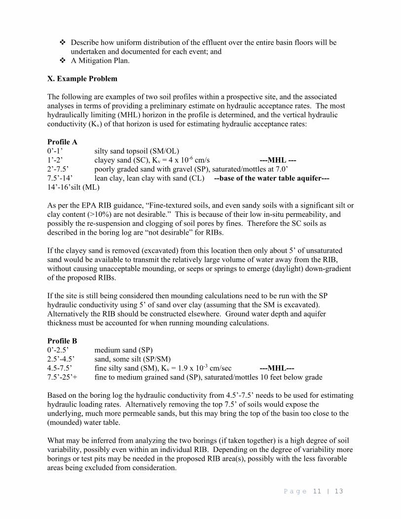
A Mitigation Plan. X. Example Problem The following are examples of two soil profiles within a prospective site, and the associated analyses in terms of providing a preliminary estimate on hydraulic acceptance rates. The most hydraulically limiting (MHL) horizon in the profile is determined, and the vertical hydraulic conductivity (Kv) of that horizon is used for estimating hydraulic acceptance rates: Profile A 0’-1’ silty sand topsoil (SM/OL) 1’-2’ clayey sand (SC), Kv = 4 x 10⁻⁶ cm/s ---MHL --- 2’-7.5’ poorly graded sand with gravel (SP), saturated/mottles at 7.0’ 7.5’-14’ lean clay, lean clay with sand (CL) --base of the water table aquifer--- 14’-16’silt (ML) As per the EPA RIB guidance, “Fine-textured soils, and even sandy soils with a significant silt or clay content (>10%) are not desirable.” This is because of their low in-situ permeability, and possibly the re-suspension and clogging of soil pores by fines. Therefore the SC soils as described in the boring log are “not desirable” for RIBs. If the clayey sand is removed (excavated) from this location then only about 5’ of unsaturated sand would be available to transmit the relatively large volume of water away from the RIB, without causing unacceptable mounding, or seeps or springs to emerge (daylight) down-gradient of the proposed RIBs. If the site is still being considered then mounding calculations need to be run with the SP hydraulic conductivity using 5’ of sand over clay (assuming that the SM is excavated). Alternatively the RIB should be constructed elsewhere. Ground water depth and aquifer thickness must be accounted for when running mounding calculations. Profile B 0’-2.5’ medium sand (SP) 2.5’-4.5’ sand, some silt (SP/SM) 4.5-7.5’ fine silty sand (SM), Kv = 1.9 x 10⁻³ cm/sec ---MHL--- 7.5’-25’+ fine to medium grained sand (SP), saturated/mottles 10 feet below grade Based on the boring log the hydraulic conductivity from 4.5’-7.5’ needs to be used for estimating hydraulic loading rates. Alternatively removing the top 7.5’ of soils would expose the underlying, much more permeable sands, but this may bring the top of the basin too close to the (mounded) water table. What may be inferred from analyzing the two borings (if taken together) is a high degree of soil variability, possibly even within an individual RIB. Depending on the degree of variability more borings or test pits may be needed in the proposed RIB area(s), possibly with the less favorable areas being excluded from consideration.
P a g e 12 | 13
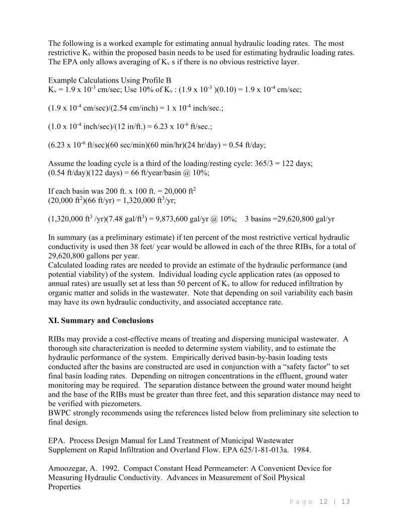
The following is a worked example for estimating annual hydraulic loading rates. The most restrictive Kv within the proposed basin needs to be used for estimating hydraulic loading rates. The EPA only allows averaging of Kv s if there is no obvious restrictive layer. Example Calculations Using Profile B Kv = 1.9 x 10⁻³ cm/sec; Use 10% of Kv : (1.9 x 10⁻³ )(0.10) = 1.9 x 10⁻⁴ cm/sec; (1.9 x 10⁻⁴ cm/sec)/(2.54 cm/inch) = 1 x 10⁻⁴ inch/sec.; (1.0 x 10⁻⁴ inch/sec)/(12 in/ft.) = 6.23 x 10⁻⁶ ft/sec.; (6.23 x 10⁻⁶ ft/sec)(60 sec/min)(60 min/hr)(24 hr/day) = 0.54 ft/day; Assume the loading cycle is a third of the loading/resting cycle: 365/3 = 122 days; (0.54 ft/day)(122 days) = 66 ft/year/basin @ 10%; If each basin was 200 ft. x 100 ft. = 20,000 ft2
(20,000 ft2)(66 ft/yr) = 1,320,000 ft3/yr; (1,320,000 ft3 /yr)(7.48 gal/ft3) = 9,873,600 gal/yr @ 10%; 3 basins =29,620,800 gal/yr In summary (as a preliminary estimate) if ten percent of the most restrictive vertical hydraulic conductivity is used then 38 feet/ year would be allowed in each of the three RIBs, for a total of 29,620,800 gallons per year. Calculated loading rates are needed to provide an estimate of the hydraulic performance (and potential viability) of the system. Individual loading cycle application rates (as opposed to annual rates) are usually set at less than 50 percent of Kv to allow for reduced infiltration by organic matter and solids in the wastewater. Note that depending on soil variability each basin may have its own hydraulic conductivity, and associated acceptance rate. XI. Summary and Conclusions RIBs may provide a cost-effective means of treating and dispersing municipal wastewater. A thorough site characterization is needed to determine system viability, and to estimate the hydraulic performance of the system. Empirically derived basin-by-basin loading tests conducted after the basins are constructed are used in conjunction with a “safety factor” to set final basin loading rates. Depending on nitrogen concentrations in the effluent, ground water monitoring may be required. The separation distance between the ground water mound height and the base of the RIBs must be greater than three feet, and this separation distance may need to be verified with piezometers. BWPC strongly recommends using the references listed below from preliminary site selection to final design. EPA. Process Design Manual for Land Treatment of Municipal Wastewater Supplement on Rapid Infiltration and Overland Flow. EPA 625/1-81-013a. 1984. Amoozegar, A. 1992. Compact Constant Head Permeameter: A Convenient Device for Measuring Hydraulic Conductivity. Advances in Measurement of Soil Physical Properties

P a g e 13 | 13
Finnemore, E.J and N. N. Hantzsche. June 1983. Ground-Water Mounding Due to OnSite Sewage Disposal. Journal of Irrigation Drainage Engineering. Vol. 109, No. 2.