Embed Size (px)
DESCRIPTION
Guide for applying isam methid
Citation preview
0 Guidance Document for Integrated Safety Assessment Methodology
Guidance Document for Integrated Safety Assessment Methodology (ISAM) (GDI)
European Commission Joint Research Centre report prepared for GIF Risk
and Safety Working Group
Version 1.0 Approved on 12 May 2014
GIF/RSW G/2014/001
1 Guidance Document for Integrated Safety Assessment Methodology
Table of Contents
1. Preamble ..................................................................................................................... 2
1.1 Recall about the ISAM methodology .................................................................. 2 1.2 Terms of reference for this Guidance Document ............................................. 3 1.3 Methods & Process ............................................................................................... 3 1.4 ................................................................................. 3
2. Introduction ............................................................................................................... 4 3. Guidance to use ISAM to address the safety related concerns ............................. 5
3.1 ............................................. 5 3.1.1 Safety assessment and safety analysis following the IAEA ...................... 5 3.1.2 The flowchart for the design and the assessment .................................... 5 3.1.3 The risk Informed approach for an improved implementation of
Defence-in-Depth principle .......................................................................... 7 3.2 The ISAM methodology ....................................................................................... 9 3.3 Safety assessment and verification: the role of ISAM.....................................11
3.3.1 Crosscutting relationships between the flowchart for the design and the assessment and the different tools of ISAM .......................................11
3.3.2 Role and position of the ISAM tools within the flowchart for the design and the assessment ......................................................................................12
3.3.3 Use of the ISAM tools within flowchart for the design and the assessment ....................................................................................................16
3.3.4 Use of the ISAM tools with the Risk Informed Approach ........................16 3.3.5 Consistency and adequateness of the ISAM tools within the flowchart
as selected by SARGEN IV ............................................................................17 3.3.6 Consistency and adequateness of the ISAM tools with international
safety assessment requirements ................................................................18 4. Practical examples for the ISAM implementation ............................................... 19
4.1 Inputs and Outputs from each ISAM tool .........................................................19 4.1.1 Inputs and Outputs from QSR .....................................................................19 4.1.2 Inputs and Outputs from PIRT ....................................................................19 4.1.3 Inputs and Outputs from OPT .....................................................................20 4.1.4 Inputs and Outputs from DPA .....................................................................21 4.1.5 Inputs and Outputs from PSA .....................................................................21
4.2 Examples of application for the different tools ...............................................23 4.2.1 The case of the Stratified Redan (Internal vessel for a Sodium Fast
Reactor) ..........................................................................................................23 4.2.2 The case of the Japan Sodium Fast Reactor (JSFR) ....................................27 4.2.3 Summary of the ISAM Tools concatenation ..............................................33
5. Conclusions .............................................................................................................. 34 6. References ................................................................................................................ 36 Appendix 1. The glossary of the flowchart (cf. Fig.2) ............................................... 38 Appendix 2. Safety design principles ........................................................................ 42
Appendix 3. Safety requirements .............................................................................. 45 Appendix 4. Example of application of the flowchart (cf. Fig.2) for the Selection and design of the reactivity control system ....................................... 46
........................................ 47 ............ 48 ........... 51
Appendix 8. The Objective Provision Tree: Application to the JSFR concept ........ 56

2 Guidance Document for Integrated Safety Assessment Methodology
1. Preamble
1.1 Recall about the ISAM methodology
A key objective Working Group charter is the development and the qualification of an integrated methodology that can be used to evaluate and document the safety of Gen IV nuclear systems.
A first RSWG report issued in 2008 presented the Basis for the Safety Approach for Design & Assessment of Generation IV Nuclear Systems (Ref. 1).
Coherently with its mandate, RSWG prepared and delivered in 2011 a second document (Ref.2) that describes the Integrated Safety Assessment Methodology (ISAM), for use throughout the Gen IV technology development cycle.
As indicated within the Ref. 2, it is envisioned that the ISAM will be used in three principal ways:
with insights derived from the ISAM serving to influence the course of the design evolution. In this application of the methodology, the ISAM is used to develop a more detailed understanding of safety related design vulnerabilities, and resulting contributions to risk. Based on this detailed understanding of safety vulnerabilities, new safety provisions or design improvements can be identified, developed, and implemented relatively early.
Selected elements of the methodology will be applied at various points throughout the design evolution to yield an objective understanding of risk contributors, safety margins, effectiveness of safety-related design provisions, sources and impacts of uncertainties, and other safety-related issues that are important to decision makers.
The ISAM can be applied in the late stages of design maturity to measure the level of safety and risk associated with a given design relative to safety objectives or licensing criteria. In this way, the ISAM will allow evaluation of a particular Gen IV concept or
post facto application of the ISAM will be especially useful for decision makers and regulators who require objective measures of safety for licensing purposes, or to support certain late-stage design selection decisions.
The methodology is NOT intended to dictate design requirements, to dictate compliance with quantitative safety goals, or to constrain designers in any other way. The sole intent is to provide a useful methodology that contributes to the attainment of Generation IV safety objectives, that yields useful insights into the nature of safety and risk of Generation IV systems, and that permits meaningful evaluations of Generation IV concepts with respect to safety
Coherently with the objectives discussed within the Ref. 1, the methodology is intended to support the achievement of a safety that is built-in added on
The methodology has been presented to the different Gen IV System Steering Committees during a specific workshop organized in April 2010 in JRC/Petten. Following the workshop and the release of the Ref. 2, comments and suggestions were collected.
Among these comments and suggestions there are the explicit need for having a more detailed description/justification about the "integration" of the different ISAM tools, as well as the request for further practical guidelines for its application.
3 Guidance Document for Integrated Safety Assessment Methodology
1.2 Terms of reference for this Guidance Document
To answer the comments and suggestions, as part of facilitating the use of the methodology, the RSWG identified the need to develop a supporting Guidance Document for ISAM (GDI) to provide the users with further help for the ISAM implementation.
This document has been prepared according to the following objectives:
1) To provide a step-by-step description on how to apply ISAM:
a) to identify the inputs and outputs of the different tools; b) to explain the flow from one step to another; c) to elaborate a flow chart in support.
2) To illustrate a pilot application of ISAM to a specific system or part of system as an example.
The GDI has been prepared taking into consideration the experience gained with application of ISAM to several innovative design solutions (Ref. 3).
1.3 Methods & Process
The following topics are expected to be addressed by the GDI document:
The proof of consistency/adequacy between on one side the ISAM tools and structure and, on the other side, the current requirements and recommendations applicable to future nuclear systems;
A summary of ISAM describing, for the different tools,
– the inputs and outputs; – their mutual dependencies.
The precise definition of the possible role and contribution of each ISAM tool versus the different plant design status (pre-conceptual, conceptual, final; i.e. the step-by-step application of ISAM). It is proposed that either the single case of a given design status (e.g. conceptual design) is considered with the application of the five tools or several distinctive combinations of some of the five tools are analysed.
The EU/JRC accepted to organize and finance the task for the preparation of the GDI first draft, which was then reviewed and adopted by GIF RSWG members.
1.4 /Deliverables
Coherently with the objectives recalled within the §1.2, the following outputs/outcomes are expected from this GDI:
Potential ISAM users shall achieve an improved understanding of the proposed methodology.
All parties (RSWG/ISAM users) shall develop a level of confidence and understanding of the methodology through the development of the pilot application.
The GDI could be put in annex to the methodology document or its insights could
serve as basis for the review of the document itself. It is the latter approach that is
adopted within the document.
4 Guidance Document for Integrated Safety Assessment Methodology
2. Introduction
Among the comments and suggestions collected from the possible users of the Integrated Safety Assessment Methodology (ISAM) there are the explicit need for having a more detailed description/justification about the "integration" of the different ISAM tools, as well as the request for further practical guidelines on its application.
The Guidance Document for ISAM (GDI) is prepared to answer these comments and suggestions and to provide the users with further help for the ISAM implementation.
Within the context of this document the notion of integration should be interpreted both:
1) regarding the general context which characterize the activities of design and assessment for innovative nuclear systems and
2) the proof of complementarity and completeness of the whole set of tools to meet the searched objectives as they are presented within the section §1.1 above:
– The ISAM is intended for use throughout the concept development and design phases with insights derived from the ISAM serving to influence the course of the design evolution.
– to yield an objective understanding of risk contributors, safety margins, effectiveness of safety-related design provisions, etc.
– The ISAM can be applied in the late stages of design maturity to measure the level of safety and risk associated with a given design relative to safety objectives or licensing criteria.
Concerning the first bullet the objective is to check the consistency and the adequateness of ISAM to address the safety related concerns raised by the design and the assessment of innovative systems (i.e. the safety related
/ )1. Such consistency and adequateness shall be verified using, as terms of comparison and as far as feasible, indications coming from institutions and agencies which are recognized as references for the safety concerns: the International Atomic Energy Agency (IAEA), the Western European
, National Regulators, International programs (MDEP, GIF, INPRO), etc.
The second bullet addresses the need for practical examples where inputs and outputs of each tool are clearly identified as well as the mutual interactions among the tools. On this theme one must be aware that a full scope example would be relatively heavy to do and so, within the GDI only punctual examples, i.e. focusing on a given provision or a whole nuclear system, are developed and presented.
Following this logic, the document content is divided into two parts. The first one focuses on the demonstration of the consistency and the adequateness of ISAM for the / , and the second one provides a set of examples which will help the designers to develop their own applications.
1 It is worth noting that the compliance with this objective do not impair the possibility for the
methodology to be used/applied to assess the safety level of designs already defined/available, i.e. for plants already in operation or under construction.
5 Guidance Document for Integrated Safety Assessment Methodology
3. Guidance to use ISAM to address the safety related concerns
3.1
3.1.1 Safety assessment and safety analysis following the IAEA
According to the definition of IAEA (Ref. 4), the safety assessment is the systematic process that is carried out throughout the design process to ensure that all the relevant safety requirements are met by the proposed (or actual) design of the plant. This would include also the requirements set by the operating organization and the regulators. Safety assessment includes, but is not limited to, the formal safety analysis .
Still following the IAEA: The design and the safety assessment are part of the same iterative process conducted by the plant designer which continues until a design solution meets all the requirements for management of safety, the principal technical requirements, the plant design and plant system design requirements (cf. for example Ref. 5) and that a comprehensive safety analysis has been carried out
Regarding safety analysis, IAEA (Ref. 5 Requirement 42) A safety analysis of the design for the nuclear power plant shall be conducted in which methods of both deterministic analysis and probabilistic analysis shall be applied
the design basis for items important to safety and their links to initiating events and event sequences shall be confirmed.
It shall be demonstrated that the nuclear power plant as designed is capable of meeting acceptable limits for accident conditions.
The safety analysis shall provide assurance that defence in depth has been implemented provide assurance that uncertainties have been given adequate consideration
According to these indications the safety assessment is first of all the qualitative check that the system and its safety architecture are compatible with the principles, the requirements and the guidelines formulated by agencies and organizations responsible for verifying the safety of the installations.
The safety analysis, which is integral part of this assessment, verifies the conformity with the quantitative safety objectives including the uncertainties; this conformity guarantees the protection which is requested for the operators, the public and the environment.
3.1.2 The flowchart for the design and the assessment
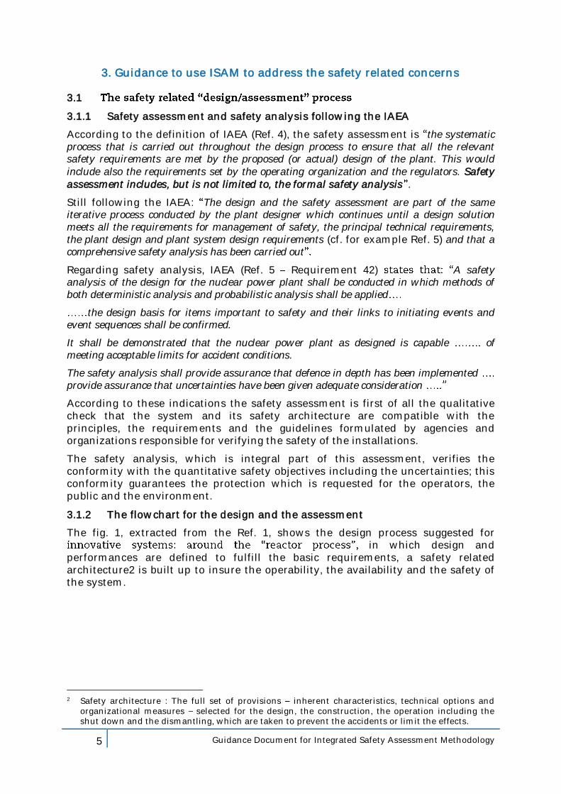
The fig. 1, extracted from the Ref. 1, shows the design process suggested for in which design and
performances are defined to fulfill the basic requirements, a safety related architecture2 is built up to insure the operability, the availability and the safety of the system.
2 Safety architecture : The full set of provisions inherent characteristics, technical options and
organizational measures selected for the design, the construction, the operation including the shut down and the dismantling, which are taken to prevent the accidents or limit the effects.
6 Guidance Document for Integrated Safety Assessment Methodology
Figure 1: Iterative process for the construction of the safety architecture
The design process, as shown in Fig. 1, is obviously part of a wider context into which the designer has to integrate the principles, the recommendations and the other guidelines which come from the regulator(s); in this context the designer develops his safety approach, that is: defines the strategy, chooses safety goals and objectives as well as the safety options which form the base of the architecture which is organized to guarantee the safety of the installation. Once this approach is defined and the situations which have to be considered for the design basis identified, the construction of the safety architecture can begin with the selection and the sizing of provisions to be implemented.
The overall process is first the object of a self assessment by the designer to ensure that safety objectives are met. Once this step achieved, it is the entire process, including the results of this assessment, which is submitted for discussion/endorsement to the regulator3.
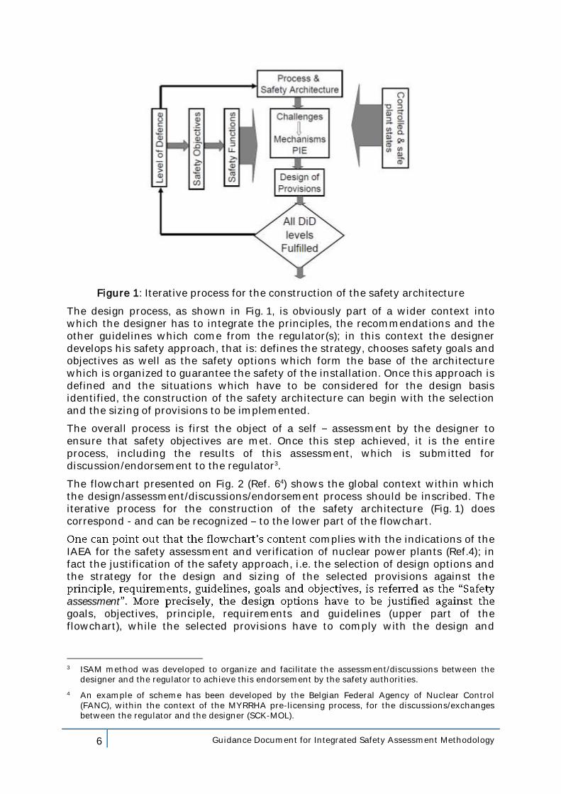
The flowchart presented on Fig. 2 (Ref. 64) shows the global context within which the design/assessment/discussions/endorsement process should be inscribed. The iterative process for the construction of the safety architecture (Fig. 1) does correspond - and can be recognized to the lower part of the flowchart.
omplies with the indications of the IAEA for the safety assessment and verification of nuclear power plants (Ref.4); in fact the justification of the safety approach, i.e. the selection of design options and the strategy for the design and sizing of the selected provisions against the
assessmentgoals, objectives, principle, requirements and guidelines (upper part of the flowchart), while the selected provisions have to comply with the design and
3 ISAM method was developed to organize and facilitate the assessment/discussions between the
designer and the regulator to achieve this endorsement by the safety authorities.
4 An example of scheme has been developed by the Belgian Federal Agency of Nuclear Control (FANC), within the context of the MYRRHA pre-licensing process, for the discussions/exchanges between the regulator and the designer (SCK-MOL).
7 Guidance Document for Integrated Safety Assessment Methodology
operational safety specifications established for them (i.e. through the safety analysis; bottom part of the flowchart).
Figure 2: Flowchart for the design/assessment/discussions/endorsement process; scheme for the design and the implementation of the safety architecture
guideline to check the consistency and the adequateness of ISAM to address the safety related concerns raised by the design and the assessment of innovative systems.
To avoid, or at least reduce, the risk of ambiguity in the interpretation of the flowchart, the meaning of terms used within the figure 2 is detailed within the Appendix 1 (coupled with Appendix 2 & 3).
As a matter of example, the Appendix 4 (cf. Fig. 2bis) shows an example of flow chart content for the selection and the design of provisions related to the reactivity control.
3.1.3 The risk Informed approach for an improved implementation of Defence-in-Depth principle
As outlined by the Ref. 1, the final acceptability of a concept should remain based on the degree of meeting the Defence-in-Depth (DiD) principles. The strategy of DiD (i.e. the adoption of adequate safety architectures) ensures that the fundamental safety functions are reliably achieved and with sufficient margins to compensate for equipment failure, human errors and hazards, including the uncertainty associated with estimating such events. This can be done through homogeneous coverage of the risk domain from frequent abnormal events to very low frequency high consequence accidents including events with large uncertainty even very low
uch as extreme external hazards that the designer will be asked to consider in case-by-case manner.
8 Guidance Document for Integrated Safety Assessment Methodology
This coverage is attained by using the best data from experience feedback (when available) for improving the quality of data and analyses, and developing a systematic methodology to identify and manage the risks. Moreover, this methodology has so to merge Defence-in-Depth and probabilistic insights generating a Risk Informed approach.
risk insights are considered together with other factors to establish requirements that better focus the attention on design and operational issues commensurate with their importance to health and safety
Such a philosophy enhances the traditional approach by:
(a) allowing explicit consideration of a broader set of potential challenges to safety,
(b) providing a logical means for prioritizing these challenges based on risk significance, operating experience, and/or engineering judgment,
(c) facilitating consideration of a broader set of resources to defend against these challenges,
(d) explicitly identifying and quantifying sources of uncertainty in the analysis, and
(e) leading to better decision-making by providing a means to test the sensitivity of the results to key assumptions.
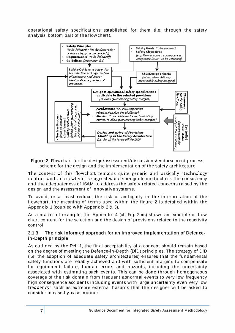
The Fig. 3 (Ref. 1) summarizes the logic suggested by the Ref. 1:
Safety Goals & Objectives
Fundamental Safety Functions
Defence in Depth levels :1st – Prevention2nd- Surveillance and control3rd – Accident management4th – Control of Severe Conditions and Mitigation5th – Mitigation of radiological Consequences
Risk Informedtechnical & operational
safety requirementsapplicable to the design
Probabilisticsuccess criteria
Deterministicsuccess criteria
Figure 3: Defence in depth and Risk-Informed Safety Philosophy
The deterministic and probabilistic considerations, including success criteria, are therefore integrated into the comprehensive implementation of defence in depth.
Such success criteria are essential to correctly design the provisions that implement the levels of the DiD; the performances of these provisions have to be defined in terms of physical performances and required reliability; finally the provisions have to be if needed/justified safety classified. The final goal of this process is the optimization of the whole safety related architecture in terms of performances, reliability and costs.
9 Guidance Document for Integrated Safety Assessment Methodology
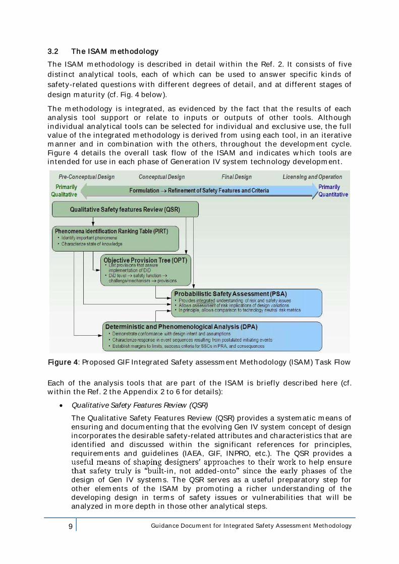
3.2 The ISAM methodology
The ISAM methodology is described in detail within the Ref. 2. It consists of five
distinct analytical tools, each of which can be used to answer specific kinds of
safety-related questions with different degrees of detail, and at different stages of
design maturity (cf. Fig. 4 below).
The methodology is integrated, as evidenced by the fact that the results of each analysis tool support or relate to inputs or outputs of other tools. Although individual analytical tools can be selected for individual and exclusive use, the full value of the integrated methodology is derived from using each tool, in an iterative manner and in combination with the others, throughout the development cycle. Figure 4 details the overall task flow of the ISAM and indicates which tools are intended for use in each phase of Generation IV system technology development.
Figure 4: Proposed GIF Integrated Safety assessment Methodology (ISAM) Task Flow
Each of the analysis tools that are part of the ISAM is briefly described here (cf. within the Ref. 2 the Appendix 2 to 6 for details):
Qualitative Safety Features Review (QSR)
The Qualitative Safety Features Review (QSR) provides a systematic means of ensuring and documenting that the evolving Gen IV system concept of design incorporates the desirable safety-related attributes and characteristics that are identified and discussed within the significant references for principles, requirements and guidelines (IAEA, GIF, INPRO, etc.). The QSR provides a
to help ensure -in, not added-
design of Gen IV systems. The QSR serves as a useful preparatory step for other elements of the ISAM by promoting a richer understanding of the developing design in terms of safety issues or vulnerabilities that will be analyzed in more depth in those other analytical steps.
10 Guidance Document for Integrated Safety Assessment Methodology
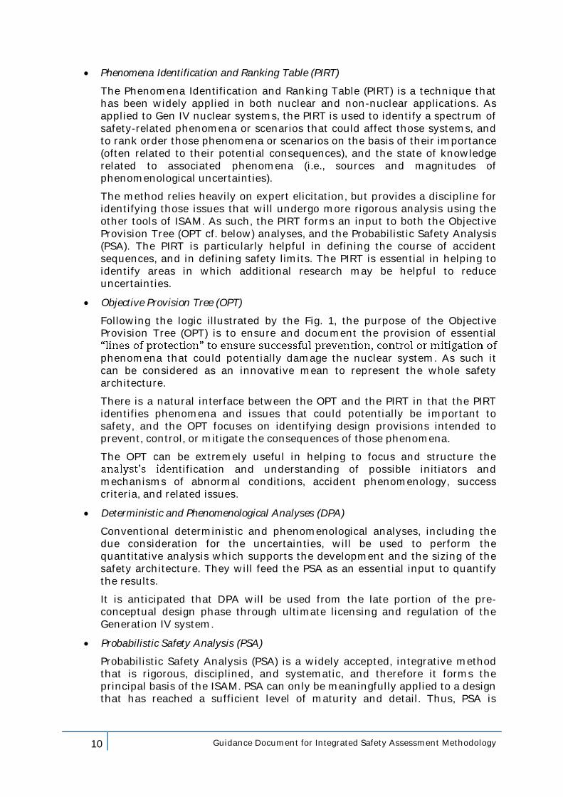
Phenomena Identification and Ranking Table (PIRT)
The Phenomena Identification and Ranking Table (PIRT) is a technique that has been widely applied in both nuclear and non-nuclear applications. As applied to Gen IV nuclear systems, the PIRT is used to identify a spectrum of safety-related phenomena or scenarios that could affect those systems, and to rank order those phenomena or scenarios on the basis of their importance (often related to their potential consequences), and the state of knowledge related to associated phenomena (i.e., sources and magnitudes of phenomenological uncertainties).
The method relies heavily on expert elicitation, but provides a discipline for identifying those issues that will undergo more rigorous analysis using the other tools of ISAM. As such, the PIRT forms an input to both the Objective Provision Tree (OPT cf. below) analyses, and the Probabilistic Safety Analysis (PSA). The PIRT is particularly helpful in defining the course of accident sequences, and in defining safety limits. The PIRT is essential in helping to identify areas in which additional research may be helpful to reduce uncertainties.
Objective Provision Tree (OPT)
Following the logic illustrated by the Fig. 1, the purpose of the Objective Provision Tree (OPT) is to ensure and document the provision of essential
phenomena that could potentially damage the nuclear system. As such it can be considered as an innovative mean to represent the whole safety architecture.
There is a natural interface between the OPT and the PIRT in that the PIRT identifies phenomena and issues that could potentially be important to safety, and the OPT focuses on identifying design provisions intended to prevent, control, or mitigate the consequences of those phenomena.
The OPT can be extremely useful in helping to focus and structure the tification and understanding of possible initiators and
mechanisms of abnormal conditions, accident phenomenology, success criteria, and related issues.
Deterministic and Phenomenological Analyses (DPA)
Conventional deterministic and phenomenological analyses, including the due consideration for the uncertainties, will be used to perform the quantitative analysis which supports the development and the sizing of the safety architecture. They will feed the PSA as an essential input to quantify the results.
It is anticipated that DPA will be used from the late portion of the pre-conceptual design phase through ultimate licensing and regulation of the Generation IV system.
Probabilistic Safety Analysis (PSA)
Probabilistic Safety Analysis (PSA) is a widely accepted, integrative method that is rigorous, disciplined, and systematic, and therefore it forms the principal basis of the ISAM. PSA can only be meaningfully applied to a design that has reached a sufficient level of maturity and detail. Thus, PSA is
11 Guidance Document for Integrated Safety Assessment Methodology
performed and iterated beginning in the late pre-conceptual design phase, and continuing until the final design stages.
the RSWG advocates the idea of applying PSA at the earliest practical point in the design process, and continuing to use it as a key decision tool throughout the life of the plant or system.
Although the other elements of the ISAM have significant value as stand-alone analysis methods, their value is enhanced by the fact that they serve as useful tools in helping to prepare for and to shape the PSA once the design has matured to a point where the PSA can be successfully applied.
3.3 Safety assessment and verification: the role of ISAM
3.3.1 Crosscutting relationships between the flowchart for the design and the assessment and the different tools of ISAM
Once goals, objectives, principles, requirements, guidelines and safety options have been selected, the full process (iterative as needed) for the design and the assessment of the retained safety architecture (including the safety analysis) can be summarized as follows:
1. Looking for compliance/consistency of the design options with the principles, requirements and guidelines,
2. Identification, prioritization and correction (if feasible) of discrepancies between design options with the principles, requirements and guidelines,
3. Identification of challenges to the safety functions,
4. Identification of mechanisms (initiating events) and selection of significant (envelope) plants conditions to be considered for the design basis,
5. Identification and selection of needed provisions,
6. Design and sizing of the provisions,
7. Analysis of the response to transients (safety analysis),
8. Final assessment5 for a safety architecture that should be (Ref. 1 §III.5.1):
– Exhaustive, – Progressive, – Tolerant, – Forgiving, – Balanced.
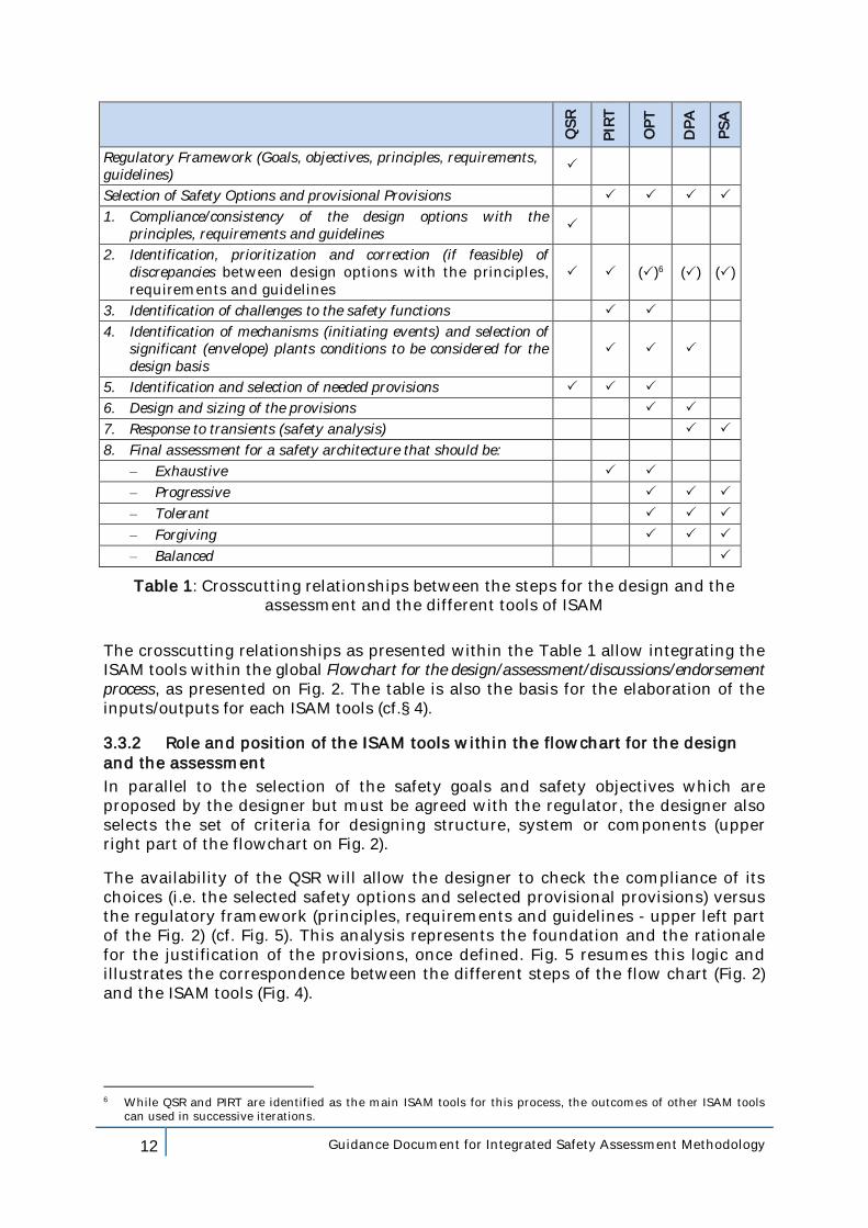
The following table 1 resumes the crosscutting relationships between, on one side, the items above and, on the other side, the different tools of ISAM and demonstrates the integrated character of the ISAM tools versus the safety assessment objective.
5 The whole process is itself an assessment of the safety architecture characteristics. The distinction here is made
between the design and sizing of the architecture and its assessment of exhaustiveness, progression, tolerance, forgivingness and balance.
12 Guidance Document for Integrated Safety Assessment Methodology
QS
R
PIR
T
OP
T
DP
A
PS
A
Regulatory Framework (Goals, objectives, principles, requirements, guidelines)
Selection of Safety Options and provisional Provisions
1. Compliance/consistency of the design options with the principles, requirements and guidelines
2. Identification, prioritization and correction (if feasible) of discrepancies between design options with the principles, requirements and guidelines
()6 () ()
3. Identification of challenges to the safety functions
4. Identification of mechanisms (initiating events) and selection of significant (envelope) plants conditions to be considered for the design basis
5. Identification and selection of needed provisions
6. Design and sizing of the provisions
7. Response to transients (safety analysis)
8. Final assessment for a safety architecture that should be:
– Exhaustive
– Progressive
– Tolerant
– Forgiving
– Balanced
Table 1: Crosscutting relationships between the steps for the design and the assessment and the different tools of ISAM
The crosscutting relationships as presented within the Table 1 allow integrating the ISAM tools within the global Flowchart for the design/assessment/discussions/endorsement process, as presented on Fig. 2. The table is also the basis for the elaboration of the inputs/outputs for each ISAM tools (cf.§ 4).
3.3.2 Role and position of the ISAM tools within the flowchart for the design and the assessment
In parallel to the selection of the safety goals and safety objectives which are proposed by the designer but must be agreed with the regulator, the designer also selects the set of criteria for designing structure, system or components (upper right part of the flowchart on Fig. 2).
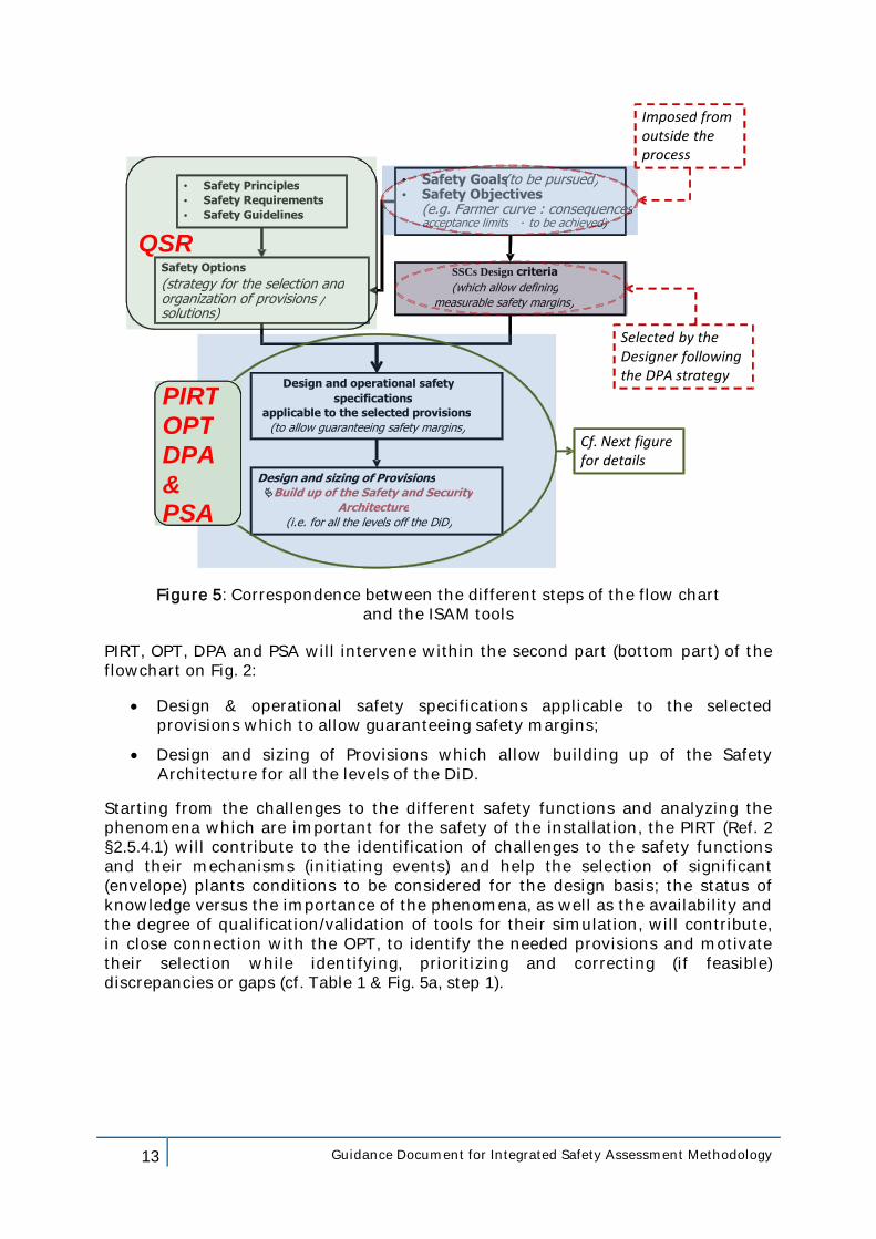
The availability of the QSR will allow the designer to check the compliance of its choices (i.e. the selected safety options and selected provisional provisions) versus the regulatory framework (principles, requirements and guidelines - upper left part of the Fig. 2) (cf. Fig. 5). This analysis represents the foundation and the rationale for the justification of the provisions, once defined. Fig. 5 resumes this logic and illustrates the correspondence between the different steps of the flow chart (Fig. 2) and the ISAM tools (Fig. 4).
6 While QSR and PIRT are identified as the main ISAM tools for this process, the outcomes of other ISAM tools
can used in successive iterations.
13 Guidance Document for Integrated Safety Assessment Methodology
• Safety Goals (to be pursued) • Safety Objectives
(e.g. Farmer curve : consequences acceptance limits - to be achieved)
SSCs Design criteria (which allow defining
measurable safety margins)
Design and operational safety specifications
applicable to the selected provisions (to allow guaranteeing safety margins)
Safety Options (strategy for the selection and organization of provisions / solutions)
Design and sizing of Provisions Build up of the Safety and Security
Architecture (i.e. for all the levels off the DiD)
• Safety Principles • Safety Requirements • Safety Guidelines
QSR
Cf. Next figure for details
Imposed from outside the process
Selected by the Designer following the DPA strategy
PIRT OPT DPA & PSA
Figure 5: Correspondence between the different steps of the flow chart and the ISAM tools
PIRT, OPT, DPA and PSA will intervene within the second part (bottom part) of the flowchart on Fig. 2:
Design & operational safety specifications applicable to the selected provisions which to allow guaranteeing safety margins;
Design and sizing of Provisions which allow building up of the Safety Architecture for all the levels of the DiD.
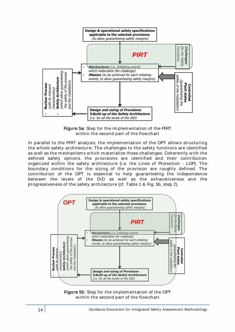
Starting from the challenges to the different safety functions and analyzing the phenomena which are important for the safety of the installation, the PIRT (Ref. 2 §2.5.4.1) will contribute to the identification of challenges to the safety functions and their mechanisms (initiating events) and help the selection of significant (envelope) plants conditions to be considered for the design basis; the status of knowledge versus the importance of the phenomena, as well as the availability and the degree of qualification/validation of tools for their simulation, will contribute, in close connection with the OPT, to identify the needed provisions and motivate their selection while identifying, prioritizing and correcting (if feasible) discrepancies or gaps (cf. Table 1 & Fig. 5a, step 1).
14 Guidance Document for Integrated Safety Assessment Methodology
Design & operational safety specificationsapplicable to the selected provisions
(to allow guaranteeing safety margins)
Design and sizing of ProvisionsBuild up of the Safety Architecture(i.e. for all the levels of the DiD)
•N
ucle
ar
Pro
ce
ss
(with its
inhere
nt
chara
cterist
ics)
•S
afe
ty A
rch
ite
ctu
re(w
hic
h a
llow
guara
nte
ein
gth
e s
afe
ty o
f th
e p
roce
ss
and t
he inst
alla
tion)
Co
ntro
lled
Pla
nt s
tate
s(g
uara
nte
ein
g th
e
safe
ty of th
e in
stalla
tion)
• Mechanisms (i.e. Initiating events which materialize the challenge)
• Mission (to be achieved for each initiatingevents, to allow guaranteeing safety margins)
Ch
alle
ng
es
(to th
e S
afe
ty Functio
ns)
PIRT
Figure 5a: Step for the implementation of the PIRT within the second part of the flowchart
In parallel to the PIRT analysis, the implementation of the OPT allows structuring the whole safety architecture. The challenges to the safety functions are identified as well as the mechanisms which materialize these challenges. Coherently with the defined safety options, the provisions are identified and their contribution organized within the safety architecture (i.e. the Lines of Protection - LOP). The boundary conditions for the sizing of the provision are roughly defined. The contribution of the OPT is essential to help guaranteeing the independence between the levels of the DiD as well as the exhaustiveness and the progressiveness of the safety architecture (cf. Table 1 & Fig. 5b, step 2).
Design & operational safety specificationsapplicable to the selected provisions
(to allow guaranteeing safety margins)
Design and sizing of ProvisionsBuild up of the Safety Architecture(i.e. for all the levels of the DiD)
•N
ucle
ar
Pro
ce
ss
(with its
inhere
nt
chara
cterist
ics)
•S
afe
ty A
rch
ite
ctu
re(w
hic
h a
llow
guara
nte
ein
gth
e s
afe
ty o
f th
e p
roce
ss
and t
he inst
alla
tion)
Co
ntro
lled
Pla
nt s
tate
s(g
uara
nte
ein
g th
e
safe
ty of th
e in
stalla
tion)
• Mechanisms (i.e. Initiating events which materialize the challenge)
• Mission (to be achieved for each initiatingevents, to allow guaranteeing safety margins)
Ch
alle
ng
es
(to th
e S
afe
ty Functio
ns)
OPT
PIRT
Figure 5b: Step for the implementation of the OPT within the second part of the flowchart
15 Guidance Document for Integrated Safety Assessment Methodology
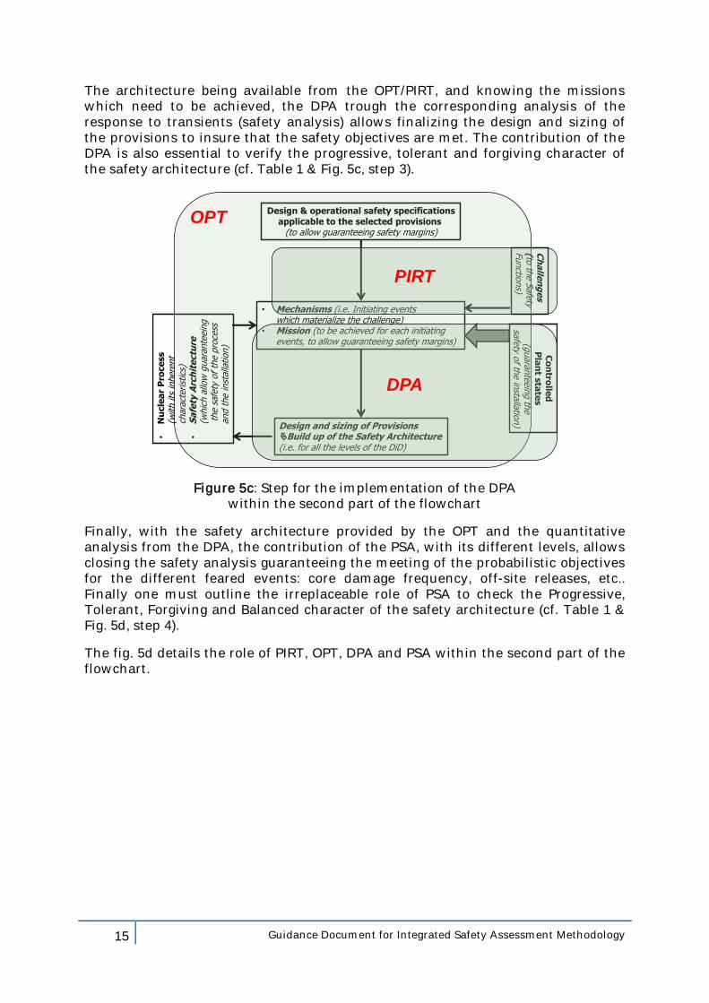
The architecture being available from the OPT/PIRT, and knowing the missions which need to be achieved, the DPA trough the corresponding analysis of the response to transients (safety analysis) allows finalizing the design and sizing of the provisions to insure that the safety objectives are met. The contribution of the DPA is also essential to verify the progressive, tolerant and forgiving character of the safety architecture (cf. Table 1 & Fig. 5c, step 3).
Design & operational safety specificationsapplicable to the selected provisions
(to allow guaranteeing safety margins)
Design and sizing of ProvisionsBuild up of the Safety Architecture(i.e. for all the levels of the DiD)
•N
ucle
ar
Pro
ce
ss
(with its
inhere
nt
chara
cterist
ics)
•S
afe
ty A
rch
ite
ctu
re(w
hic
h a
llow
guara
nte
ein
gth
e s
afe
ty o
f th
e p
roce
ss
and t
he inst
alla
tion)
Co
ntro
lled
Pla
nt s
tate
s(g
uara
nte
ein
g th
e
safe
ty of th
e in
stalla
tion)
• Mechanisms (i.e. Initiating events which materialize the challenge)
• Mission (to be achieved for each initiatingevents, to allow guaranteeing safety margins)
Ch
alle
ng
es
(to th
e S
afe
ty Functio
ns)
OPT
PIRT
DPA
Figure 5c: Step for the implementation of the DPA within the second part of the flowchart
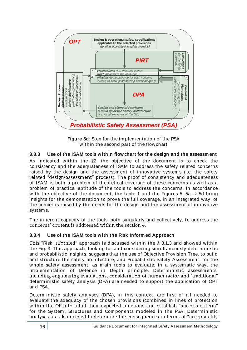
Finally, with the safety architecture provided by the OPT and the quantitative analysis from the DPA, the contribution of the PSA, with its different levels, allows closing the safety analysis guaranteeing the meeting of the probabilistic objectives for the different feared events: core damage frequency, off-site releases, etc.. Finally one must outline the irreplaceable role of PSA to check the Progressive, Tolerant, Forgiving and Balanced character of the safety architecture (cf. Table 1 & Fig. 5d, step 4).
The fig. 5d details the role of PIRT, OPT, DPA and PSA within the second part of the flowchart.
16 Guidance Document for Integrated Safety Assessment Methodology
Design & operational safety specificationsapplicable to the selected provisions
(to allow guaranteeing safety margins)
Design and sizing of ProvisionsBuild up of the Safety Architecture(i.e. for all the levels of the DiD)
•N
ucle
ar
Pro
ce
ss
(with its
inhere
nt
char
acte
rist
ics)
•S
afe
ty A
rch
ite
ctu
re(w
hic
h a
llow
guar
ante
ein
gth
e s
afety
of
the p
roce
ss
and t
he inst
alla
tion)
Co
ntro
lled
Pla
nt s
tate
s(g
uaran
teein
g th
e
safety o
f the in
stallation)
• Mechanisms (i.e. Initiating events which materialize the challenge)
• Mission (to be achieved for each initiatingevents, to allow guaranteeing safety margins)
Ch
alle
ng
es
(to th
e S
afety
Functio
ns)
Probabilistic Safety Assessment (PSA)
OPT
PIRT
DPA
Figure 5d: Step for the implementation of the PSA within the second part of the flowchart
3.3.3 Use of the ISAM tools within flowchart for the design and the assessment
As indicated within the §2, the objective of the document is to check the consistency and the adequateness of ISAM to address the safety related concerns raised by the design and the assessment of innovative systems (i.e. the safety
/ ). The proof of consistency and adequateness of ISAM is both a problem of theoretical coverage of these concerns as well as a problem of practical aptitude of the tools to address the concerns. In accordance with the objective of the document, the table 1 and the Figures 5, 5a 5d bring insights for the demonstration to prove the full coverage, in an integrated way, of the concerns raised by the needs for the design and the assessment of innovative systems.
The inherent capacity of the tools, both singularly and collectively, to address the
3.3.4 Use of the ISAM tools with the Risk Informed Approach
Risk I approach is discussed within the § 3.1.3 and showed within the Fig. 3. This approach, looking for and considering simultaneously deterministic and probabilistic insights, suggests that the use of Objective Provision Tree, to build and structure the safety architecture, and Probabilistic Safety Assessment, for the whole safety assessment, as main tools to evaluate, in a systematic way, the implementation of Defence in Depth principle. Deterministic assessments,
deterministic safety analysis (DPA) are needed to support the application of OPT and PSA.
Deterministic safety analyses (DPA), in this context, are first of all needed to evaluate the adequacy of the chosen provisions (combined in lines of protection withfor the System, Structures and Components modeled in the PSA. Deterministic
17 Guidance Document for Integrated Safety Assessment Methodology
R&D efforts, also driven by PIRT exercises, shall be conducted to support deterministic model validations as well as accident sequence outcomes assessment.
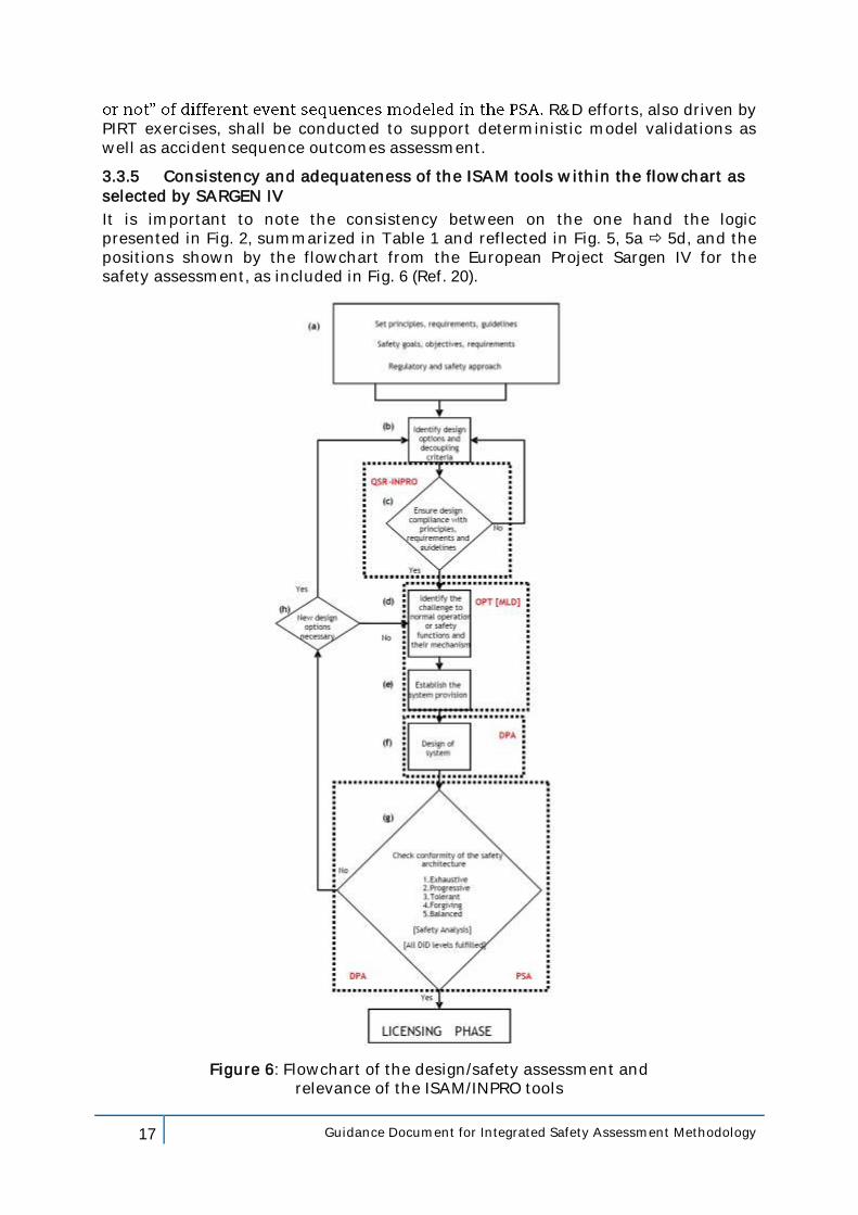
3.3.5 Consistency and adequateness of the ISAM tools within the flowchart as selected by SARGEN IV
It is important to note the consistency between on the one hand the logic presented in Fig. 2, summarized in Table 1 and reflected in Fig. 5, 5a 5d, and the positions shown by the flowchart from the European Project Sargen IV for the safety assessment, as included in Fig. 6 (Ref. 20).
Figure 6: Flowchart of the design/safety assessment and
relevance of the ISAM/INPRO tools
18 Guidance Document for Integrated Safety Assessment Methodology
The two phases of the safety assessment are clearly identified:
verification of the compliance of the system with the principles, the requirements, the guidelines defined by the regulator as well as with the safety goals and objectives developed by the designer and
verification of the conformity of the safety architecture of the system with the quantitative safety objectives, translated into physical parameters or
These phases are decomposed into basic steps that compose the overall assessment process whose iterative character is evident for both phases.
For each step the main reference tools ascribed to fulfill the tasks are highlighted.
In this respect the flowchart associates the different steps with the relevant ISAM tools showing the integrated nature of ISAM with respect to the safety assessment process.
3.3.6 Consistency and adequateness of the ISAM tools with international safety assessment requirements
The adequacy of ISAM tools to ensure the comprehensive safety evaluation of GEN IV reactor systems that would allow to demonstrate their compliance with current high level safety requirements was done with respect to the activity of the International Atomic Energy Agency (IAEA), National Regulators, International programs (GIF, INPRO), WENRA (Ref. 7-17).
Some details on the above mentioned analyses could be found in Ref. 18 and Ref. 19, where the appropriateness of QSR grid content was verified with, on one hand, the content of the INPRO methodology (Ref.18) and, on the other hand, with the contents of IAEA SSR-2/1 (Ref. 19).
Concerning the crosscut comparison with the INPRO Basic principles/ User requirements (Ref. 18), the analysis shows that improvements were required for the RSWG QSR. Similarly need for improvements are identified for the INPRO methodology. The set of RSWG/QSR recommendation has been corrected within the current version to integrate the inputs from the analysis.
The comparison between the ISAM/QSR and the IAEA SSR-2/1 (Ref. 19) proves the relevance and the pertinence of the ISAM/QSR and its recommendations. Following the comparison few corrections are suggested and need to be introduced within the QSR table in order to achieve the full consistency and to attain a set of recommendations which will be applicable to the design or the assessment of the provisions of the safety architecture of innovative nuclear system.
The analysis of these specific issues has to be done with, in the background, the recommendations which are available and applicable to the future reactors. These indications include, among others, those by WENRA (Ref. 8) which are actually under publication.
Two notions/tools appear to be perfectly consistent with the requirements proposed by WENRA (Ref. 31 §03.1): the "Line of Protection LOP", which extends
is intended as a tool for the organization of the safety architecture.
While in general good consistency was found, it is evident that for each of the GEN IV systems specific safety assessments will need to be performed to demonstrate compliance with international safety requirements.
19 Guidance Document for Integrated Safety Assessment Methodology
4. Practical examples for the ISAM implementation
4.1 Inputs and Outputs from each ISAM tool
N.B.: Details concerning each of the ISAM tools are provided within the Ref.2 (Appendix 2 to 6)
4.1.1 Inputs and Outputs from QSR
The QSR provides the designer with a check list summarizing the good practices and recommendations which can be useful to verify that the design details are coherent with the recommendations which are available from different sources, and applicable to the future nuclear systems.
The tool can be applied to a system as a whole or to a given provision, implemented to achieve a well-defined mission. Moreover the tool can be applied
to check the consistency of the system/provisions characteristics versus the good practices and recommendations;
to compare two or more solutions in order to show advantages and or disadvantages of one solution versus the other.
The inputs for the QSR are basically the utmost knowledge available of the system/provision and its behaviour.
Following the use made by the designer, the expected outputs are:
The compliance or not vis à vis the good practices and recommendations in order to identify the strong characteristics as well as the possible weakness, knowing that the latter can mask showstoppers or simply issues that should be solved to improve the performances/compliance of the solution under examination.
The advantages and or disadvantages of one solution versus the other.
Knowledge of the strengths and weaknesses of the solution, as well as the advantages or disadvantages of a solution versus another possible solution, allow the designer to identify and motivate the subsequent steps and efforts to achieve an optimized solution or, if justified, to motivate the abandonment of the solution under examination.
4.1.2 Inputs and Outputs from PIRT
The PIRT is a proven formalized subjective decision-making tool, which is exhaustive, defendable, and auditable; it provides the designer with a consistent view about what is needed to achieve, for a given design, a robust safety demonstration.
The technique helps to systematically identify system/provision vulnerabilities and generates a ranked table which helps identifying contributions to safety and risk.
for a given phenomenon, which, compared with the significance of the phenomenon, helps detecting the gaps in knowledge areas requiring additional research and data collection.
For the system/provision under examination, the PIRT is applied within the context of a given scenario/condition which follows a given initiating event; in this context it will identify, recognize, and qualify the relative importance of all relevant
20 Guidance Document for Integrated Safety Assessment Methodology
phenomena, versus selected Figure of Merit (FoM)7, with the associated rationales. This step is an essential complementary contribution to the OPT/PSA for the selection, versus a given challenge to a safety function, of initiating events which are significant from safety/risk point of view.
The advantage of the process is that it can be applied to conceptual designs as well as more mature designs. Information can be obtained on analytical tools used to simulate accident scenarios as well as on the behaviour of the process during accident scenarios.
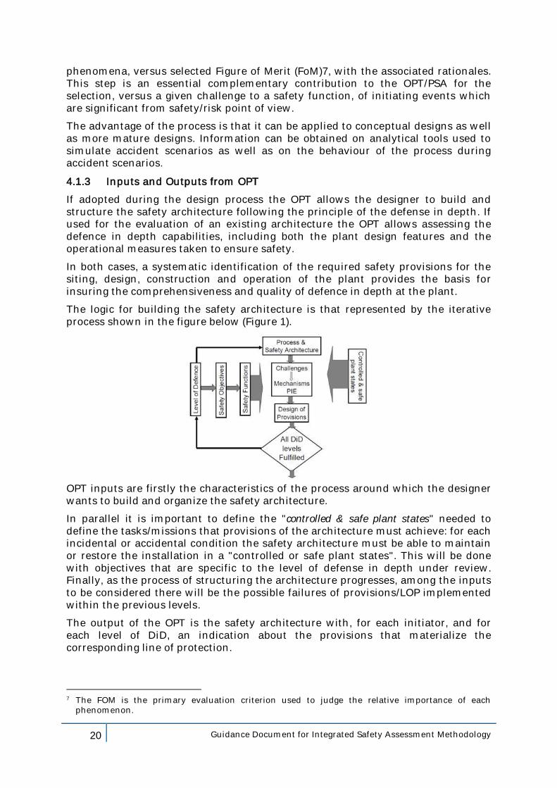
4.1.3 Inputs and Outputs from OPT
If adopted during the design process the OPT allows the designer to build and structure the safety architecture following the principle of the defense in depth. If used for the evaluation of an existing architecture the OPT allows assessing the defence in depth capabilities, including both the plant design features and the operational measures taken to ensure safety.
In both cases, a systematic identification of the required safety provisions for the siting, design, construction and operation of the plant provides the basis for insuring the comprehensiveness and quality of defence in depth at the plant.
The logic for building the safety architecture is that represented by the iterative process shown in the figure below (Figure 1).
OPT inputs are firstly the characteristics of the process around which the designer wants to build and organize the safety architecture.
In parallel it is important to define the "controlled & safe plant states" needed to define the tasks/missions that provisions of the architecture must achieve: for each incidental or accidental condition the safety architecture must be able to maintain or restore the installation in a "controlled or safe plant states". This will be done with objectives that are specific to the level of defense in depth under review. Finally, as the process of structuring the architecture progresses, among the inputs to be considered there will be the possible failures of provisions/LOP implemented within the previous levels.
The output of the OPT is the safety architecture with, for each initiator, and for each level of DiD, an indication about the provisions that materialize the corresponding line of protection.
7 The FOM is the primary evaluation criterion used to judge the relative importance of each
phenomenon.
21 Guidance Document for Integrated Safety Assessment Methodology
At this stage, the detailed design of the single provisions is not necessarily finalized because it is the role of the detailed DPA calculations to confirm the sizing of the provisions singularly and of the architecture as a whole.
4.1.4 Inputs and Outputs from DPA
As indicated above, conventional deterministic and phenomenological analyses (DPA), including the due consideration for the uncertainties, are used to perform the quantitative analysis which supports the development and the sizing of the safety architecture. All the design plant conditions both those of the Design Basis as well as those of the Design Extension Conditions are analyzed with rules which are specific to each family of conditions. DPA are used from the late portion of the pre-conceptual design phase through ultimate licensing and regulation of the Generation IV system.
Key inputs for the studies are, on one side, the safety architecture as provided, for example by the OPT - which covers all the involved provisions and their interaction and, on the other side, the physical performances of each provision. For each provision, the physical performances are the result of a specific work made by the designer as a complement of the definition of the safety architecture.
The ultimate goal being the verification that safety objectives are met, the results of the DPA (outputs) are on one hand the confirmation of the relevance of the implemented architecture as well as that of the connections between the provisions and, on the other hand, the acceptability of the design and sizing of these provisions. The possible non-compliance with the safety objectives leads the designer to be back to the input data of the studies, whether the architecture, the connections between the provisions or the provisions characteristics themselves.
4.1.5 Inputs and Outputs from PSA
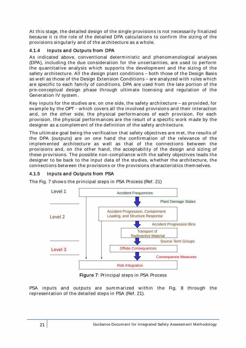
The Fig. 7 shows the principal steps in PSA Process (Ref. 21)
Accident Frequencies
Plant Damage States
Accident Progression Bins
Source Term Groups
Consequence Measures
Accident Progression, Containment
Loading, and Structure Response
Transport of
Radioactive Material
Offsite Consequences
Risk Integration
Level 1
Level 2
Level 3
Figure 7: Principal steps in PSA Process
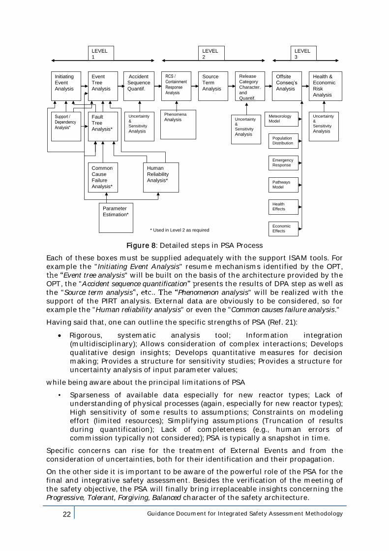
PSA inputs and outputs are summarized within the Fig. 8 through the representation of the detailed steps in PSA (Ref. 21).
22 Guidance Document for Integrated Safety Assessment Methodology
Event
Tree
Analysis
RCS /
Containment
Response
Analysis
Initiating
Event
Analysis
Accident
Sequence
Quantif.
Fault
Tree
Analysis*
Phenomena
AnalysisSupport /
Dependency
Analysis*
Uncertainty
&
Sensitivity
Analysis
Source
Term
Analysis
Release
Category
Character.
and
Quantif.
Offsite
Conseq’s
Analysis
Health &
Economic
Risk
Analysis
Common
Cause
Failure
Analysis*
Human
Reliability
Analysis*
Parameter
Estimation*
Uncertainty
&
Sensitivity
Analysis
Uncertainty
&
Sensitivity
Analysis
Meteorology
Model
Population
Distribution
Emergency
Response
Pathways
Model
Health
Effects
Economic
Effects
LEVEL
1
LEVEL
2
LEVEL
3
* Used in Level 2 as required
Figure 8: Detailed steps in PSA Process
Each of these boxes must be supplied adequately with the support ISAM tools. For example the "Initiating Event Analysis" resume mechanisms identified by the OPT,
Event tree analysis" will be built on the basis of the architecture provided by the OPT, the "Accident sequence quantification resents the results of DPA step as well as the "Source term analysis Phenomenon analysis" will be realized with the support of the PIRT analysis. External data are obviously to be considered, so for example the "Human reliability analysis" or even the "Common causes failure analysis."
Having said that, one can outline the specific strengths of PSA (Ref. 21):
Rigorous, systematic analysis tool; Information integration (multidisciplinary); Allows consideration of complex interactions; Develops qualitative design insights; Develops quantitative measures for decision making; Provides a structure for sensitivity studies; Provides a structure for uncertainty analysis of input parameter values;
while being aware about the principal limitations of PSA
• Sparseness of available data especially for new reactor types; Lack of understanding of physical processes (again, especially for new reactor types); High sensitivity of some results to assumptions; Constraints on modeling effort (limited resources); Simplifying assumptions (Truncation of results during quantification); Lack of completeness (e.g., human errors of commission typically not considered); PSA is typically a snapshot in time.
Specific concerns can rise for the treatment of External Events and from the consideration of uncertainties, both for their identification and their propagation.
On the other side it is important to be aware of the powerful role of the PSA for the final and integrative safety assessment. Besides the verification of the meeting of the safety objective, the PSA will finally bring irreplaceable insights concerning the Progressive, Tolerant, Forgiving, Balanced character of the safety architecture.
23 Guidance Document for Integrated Safety Assessment Methodology
4.2 Examples of application for the different tools
4.2.1 The case of the Stratified Redan (Internal vessel for a Sodium Fast Reactor)
4.2.1.1 Example of application for the QSR
The Ref.23 presents a first application of the ISAM/QSR on an innovative concept which was under design and assessment at the CEA/DEN/DER: the so called
(cf. Ref. 22 and Appendix 5 for a short description of the concept).
The concept of Stratified Redan for the reactor internals is compared with the conventional EFR solution to identify the favourable as well as the unfavourable characteristics of this innovative solution.
The exercise shows that the tool is capable to help the designer to qualitatively assess the design options identifying strong characteristics or safety vulnerabilities.
This is obviously one step of an iterative process where the designer is invited to
improvements or alternative solutions.
The Appendix 6 is an excerpt of the ISAM/QSR application including some key conclusions (in red) from the Ref. 23 to give an idea of the nature of the insights which can be provided by the analysis.
4.2.1.2 Example of application for the PIRT
Within the Ref.24, as a matter of example, the PIRT is implemented for the Stratified REDAN for three plant conditions:
the nominal operational conditions;
one transient configuration: the abrupt rundown for the pumps which are located on the primary heat exchanger;
earthquake.
Within the Ref.25 the PIRT is implemented, still for the Stratified REDAN concept, for the transition forced natural convectiondown) to achieve a status where the decay heat is fully be removed in natural convention.
The Appendix 7 is an excerpt of the ISAM/PIRT analysis including the identification of the figures of merit (FOM) and some conclusions from the Ref. 25 to give an idea of the nature of the insights which can be provided by the analysis.
4.2.1.3 Example of application for the OPT
4.2.1.3.1 OPT Generalities
At least two examples of application of the OPT method are available in the open literature. The first in order of time is the IAEA Tecdoc 1366 (Ref. 26) which deals with the safety architecture of the Modular High Temperature Gas Reactor (MHTGR).
The second is presented within the IAEA SR 46 (Ref. 27). In this reference, a test application of the screening method has been performed by the IAEA in collaboration with the staff of the Bohunice plant8 within the framework of the preparation of the safety upgrading program for the V-2 plants.
8 The Bohunice V-2 plant consists of two units equipped with WWER 440/V213 reactors.
24 Guidance Document for Integrated Safety Assessment Methodology
The objective of the Ref. 26 was to propose a technical basis and methodology, based on principles of defence in depth, for conducting design safety assessments and, in the long term, generating design safety requirements for innovative reactors.
The MHTGR was used as an example to illustrate this process. The document provides an overview of the safety related features of current MHTGR technology, examines how the defence in depth principle can be implemented/adopted by the MHTGR design, and how MHTGR designs could satisfy the three fundamental safety objectives: 1) general nuclear safety; 2) radiation protection; 3) technical safety. The application to MHTGRs, although very preliminary, proved that the method is viable and useful.
The Ref. 26 recognizes that the top-down approach, as discussed within the report, is applicable to any kind of reactor, however, how defence in depth is implemented and the implications on safety requirements remain concept specific.
The Ref. 27 recognizes that the screening approach, which uses objective trees, offers a user friendly tool for determining the strengths and weaknesses of defence in depth at a specific plant. The top down approach has been used for the development of objective trees, i.e. from the objectives of each level of defence down to the challenges and mechanisms, and finally to the provisions. A demonstration of defence in depth in a comprehensive and systematic way may provide reassurance for the plant operators that their safety strategy is sound and well balanced among the levels of defence. From a regulatory point of view, identification of deficiencies of defence in depth might be a valuable complement to traditional regulatory approaches.
A third comprehensive example of OPT application has been elaborated by the JAEA on the JSFR concept. A set of twelve trees, for the different safety functions and for the different levels of the DiD, has been provided within the framework of the GIF RSWG activities. The set is presented within the Appendix 8.
A comprehensive OPT for a nonspecific pool type SFR is not available within the literature.
Nevertheless, in terms of generic approach, one can consider that the example provided for the JSFR within the Appendix 7 of the Ref. 2 can be used as a basis for the analysis.
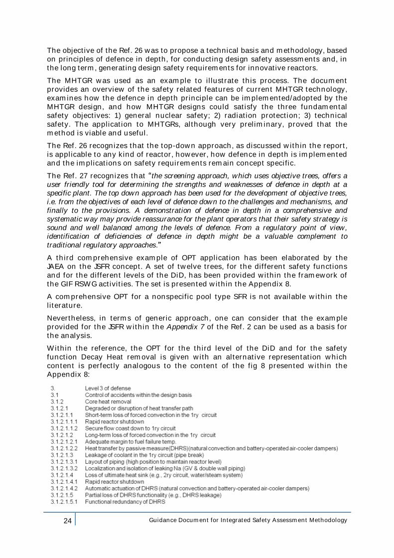
Within the reference, the OPT for the third level of the DiD and for the safety function Decay Heat removal is given with an alternative representation which content is perfectly analogous to the content of the fig 8 presented within the Appendix 8:
25 Guidance Document for Integrated Safety Assessment Methodology
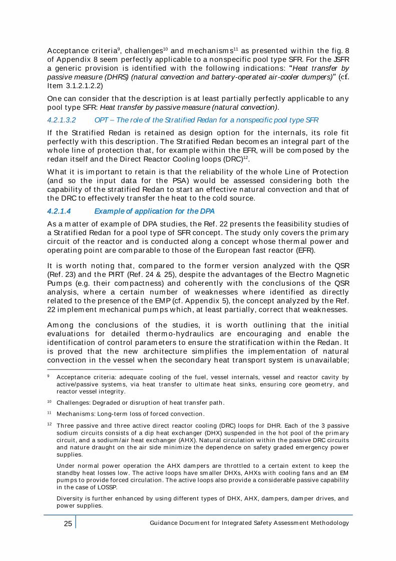
Acceptance criteria9, challenges10 and mechanisms11 as presented within the fig. 8 of Appendix 8 seem perfectly applicable to a nonspecific pool type SFR. For the JSFR a generic provision is identified with the following indications: Heat transfer by passive measure (DHRS) (natural convection and battery-operated air-cooler dumpers)Item 3.1.2.1.2.2)
One can consider that the description is at least partially perfectly applicable to any pool type SFR: Heat transfer by passive measure (natural convection).
4.2.1.3.2 OPT The role of the Stratified Redan for a nonspecific pool type SFR
If the Stratified Redan is retained as design option for the internals, its role fit perfectly with this description. The Stratified Redan becomes an integral part of the whole line of protection that, for example within the EFR, will be composed by the redan itself and the Direct Reactor Cooling loops (DRC)12.
What it is important to retain is that the reliability of the whole Line of Protection (and so the input data for the PSA) would be assessed considering both the capability of the stratified Redan to start an effective natural convection and that of the DRC to effectively transfer the heat to the cold source.
4.2.1.4 Example of application for the DPA
As a matter of example of DPA studies, the Ref. 22 presents the feasibility studies of a Stratified Redan for a pool type of SFR concept. The study only covers the primary circuit of the reactor and is conducted along a concept whose thermal power and operating point are comparable to those of the European fast reactor (EFR).
It is worth noting that, compared to the former version analyzed with the QSR (Ref. 23) and the PIRT (Ref. 24 & 25), despite the advantages of the Electro Magnetic Pumps (e.g. their compactness) and coherently with the conclusions of the QSR analysis, where a certain number of weaknesses where identified as directly related to the presence of the EMP (cf. Appendix 5), the concept analyzed by the Ref. 22 implement mechanical pumps which, at least partially, correct that weaknesses.
Among the conclusions of the studies, it is worth outlining that the initial evaluations for detailed thermo-hydraulics are encouraging and enable the identification of control parameters to ensure the stratification within the Redan. It is proved that the new architecture simplifies the implementation of natural convection in the vessel when the secondary heat transport system is unavailable; 9 Acceptance criteria: adequate cooling of the fuel, vessel internals, vessel and reactor cavity by
active/passive systems, via heat transfer to ultimate heat sinks, ensuring core geometry, and reactor vessel integrity.
10 Challenges: Degraded or disruption of heat transfer path.
11 Mechanisms: Long-term loss of forced convection.
12 Three passive and three active direct reactor cooling (DRC) loops for DHR. Each of the 3 passive sodium circuits consists of a dip heat exchanger (DHX) suspended in the hot pool of the primary circuit, and a sodium/air heat exchanger (AHX). Natural circulation within the passive DRC circuits and nature draught on the air side minimize the dependence on safety graded emergency power supplies.
Under normal power operation the AHX dampers are throttled to a certain extent to keep the standby heat losses low. The active loops have smaller DHXs, AHXs with cooling fans and an EM pumps to provide forced circulation. The active loops also provide a considerable passive capability in the case of LOSSP.
Diversity is further enhanced by using different types of DHX, AHX, dampers, damper drives, and power supplies.
26 Guidance Document for Integrated Safety Assessment Methodology
it is expected that the compactness of the concept will allow to a more reliable (cf. § 4.2.1.3 where the whole DHR LOP reliability is discussed) and cheaper design.
If the new concept with mechanical pumps is retained for future SFR that is not the case for the ASTRID prototype - the QSR analysis should be re-done.
At the same time, independently of the concept, the conclusions of the PIRT, especially concerning the sensitivity to the earthquake conditions, or that to vibrations (also pointed out by the QSR analysis), and the possible lacks in terms of knowledge needed to bring a robust safety demonstration, remains open and applicable.
4.2.1.5 Example of application for the PSA
No examples are available of a PSA applied to an architecture with the Stratified Redan.
4.2.1.6 Concatenation of the ISAM tools for the Stratified Redan
The interaction/concatenation between ISAM tools (Inputs - Outputs) is obviously not linear but iterative.
For example, if one considers the logic which is behind the proposal for the Stratified Redan, the following steps can be identified:
Building the OPT the designer identifies, for the third level of defense in depth, to cope with initiators/mechanisms such as "loss of sources", a passive mode for the evacuation of the residual heat (e.g. Fig. 8 of the Appendix 8); among the relevant provisions there will be for example exchangers in the hot collector (Decay heat removal (DHR) systems) with a natural convection into the primary circuit. The latter (the natural convection) is, in fact, a provision which is an intrinsic part of the line protection (LOP) which correspond to this DiD level for the DHR.
The Stratified Redan is a solution for the internals which allows for natural convection within the primary circuit and, as such, it is an integral part of LOP under consideration as identified by the OPT.
The QSR analysis of this solution highlights advantages and disadvantages, e.g. compared to the EFR type solution. In the exercise carried out in Ref. 23, one note the sensitivity to vibrations that the designer must take into account to ensure an acceptable concept behavior.
Moreover, the PIRT analysis (see Ref. 24 & 25) highlights gaps in terms of computational tools for earthquake behavior.
The DPA analysis performed in Ref. 22 show the theoretical capacity of Stratified Redan, concerning its physical performance potential, to achieve the requested missions. This analysis implicitly assumes that the problems of vibration and gaps in terms of response analysis to the earthquake are resolved.
The final analysis with the PSA considers the architecture defined by the OPT and must take into account the reliability of the entire line of protection, including that of the Stratified Redan to establish and maintain the natural convection.
Efforts motivated by QSR analysis vis-à-vis the vibration resistance, and those motivated by the PIRT for the development of appropriate tools for the analysis of

27 Guidance Document for Integrated Safety Assessment Methodology
earthquake response will ensure the required reliability and therefore the robustness of the demonstration made by the PSA.
4.2.2 The case of the Japan Sodium Fast Reactor (JSFR)
(The sections that follow include the full text of original Appendix 7 of Ref. 2 for the latter .)
4.2.2.1 The JSFR plant and its design specifications
JSFR is a loop-type sodium-cooled fast reactor: i.e., primary pumps and intermediate heat exchangers (IHX) constituting two loops of PHTS are installed outside the reactor vessel as illustrated in Fig. 9. The major design specifications are shown in Table 2. The thermal energy generated at the rated power of 3570MW heats up the primary coolant to 550 ºC at the reactor vessel outlet, then it is transferred to the secondary coolant with being heated to 520 ºC at the two IHXs. The main steam with temperature of 497 ºC and pressure of 19.2 MPa is generated at the two steam generators, and it rotates the turbine generator to produce the electric power output of 1500MW.
Power output 1500MWe/3570MWt
Number of loops in PHTS 2
Primary coolant temperature 550ºC/395ºC
Primary coolant mass flow rate 1.8 ×10⁴ kg/s
Secondary coolant temperature 520ºC/335ºC
Main steam temperature and pressure 497ºC/19.2MPa
Table 2: Major design specifications of JSFR [Ref. 28]
Steam
Generator
Reactor
Vessel
Secondary
Pump
IHX
Primary Pump
Figure 9: Schematic view of JSFR NSSS [Ref. 28]
28 Guidance Document for Integrated Safety Assessment Methodology
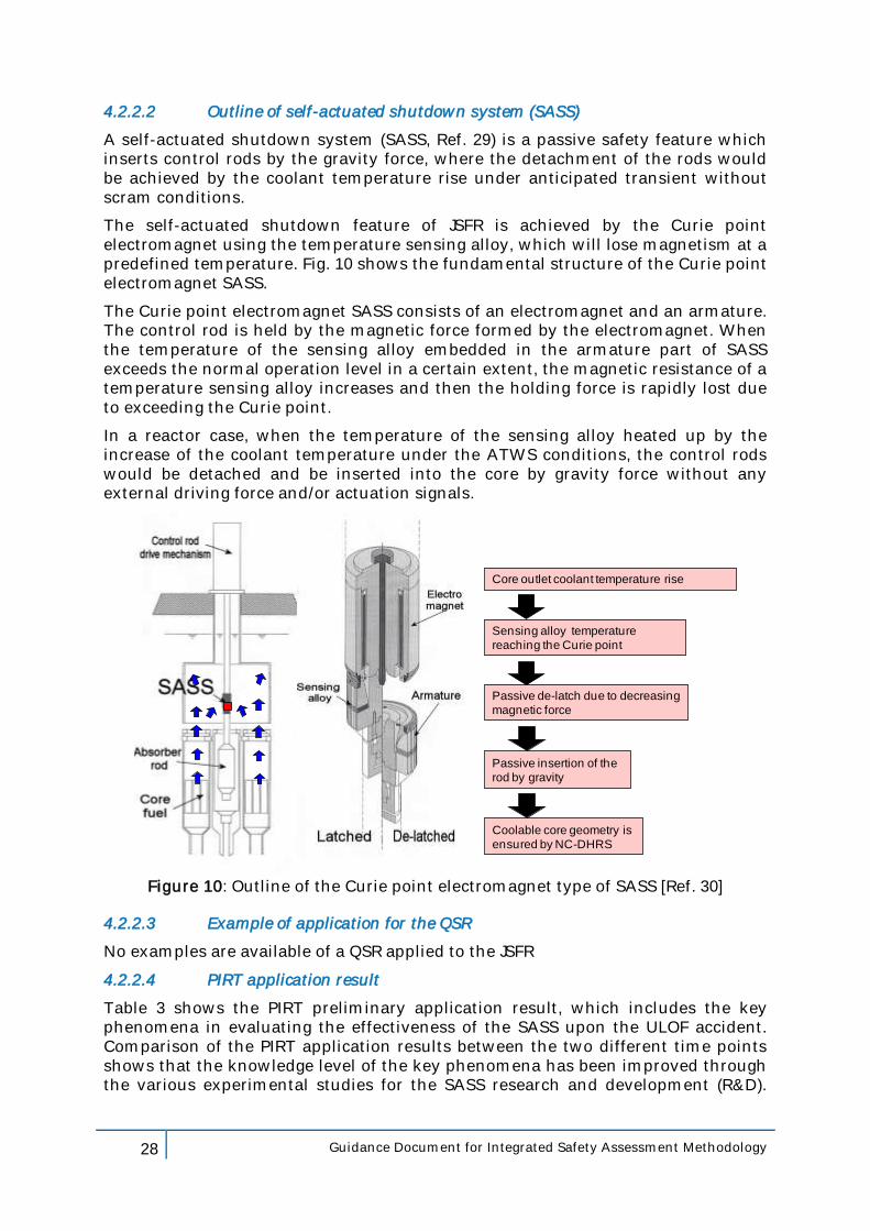
4.2.2.2 Outline of self-actuated shutdown system (SASS)
A self-actuated shutdown system (SASS, Ref. 29) is a passive safety feature which inserts control rods by the gravity force, where the detachment of the rods would be achieved by the coolant temperature rise under anticipated transient without scram conditions.
The self-actuated shutdown feature of JSFR is achieved by the Curie point electromagnet using the temperature sensing alloy, which will lose magnetism at a predefined temperature. Fig. 10 shows the fundamental structure of the Curie point electromagnet SASS.
The Curie point electromagnet SASS consists of an electromagnet and an armature. The control rod is held by the magnetic force formed by the electromagnet. When the temperature of the sensing alloy embedded in the armature part of SASS exceeds the normal operation level in a certain extent, the magnetic resistance of a temperature sensing alloy increases and then the holding force is rapidly lost due to exceeding the Curie point.
In a reactor case, when the temperature of the sensing alloy heated up by the increase of the coolant temperature under the ATWS conditions, the control rods would be detached and be inserted into the core by gravity force without any external driving force and/or actuation signals.
Core outlet coolant temperature rise
Sensing alloy temperature
reaching the Curie point
Passive de-latch due to decreasing
magnetic force
Passive insertion of the
rod by gravity
Coolable core geometry is
ensured by NC-DHRS
Figure 10: Outline of the Curie point electromagnet type of SASS [Ref. 30]
4.2.2.3 Example of application for the QSR
No examples are available of a QSR applied to the JSFR
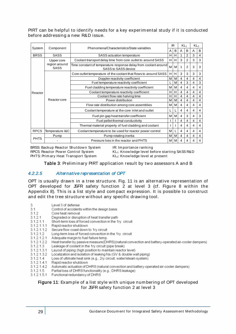
4.2.2.4 PIRT application result
Table 3 shows the PIRT preliminary application result, which includes the key phenomena in evaluating the effectiveness of the SASS upon the ULOF accident. Comparison of the PIRT application results between the two different time points shows that the knowledge level of the key phenomena has been improved through the various experimental studies for the SASS research and development (R&D).
29 Guidance Document for Integrated Safety Assessment Methodology
PIRT can be helpful to identify needs for a key experimental study if it is conducted before addressing a new R&D issue.
System Component Phenomena/Characteristics/State variablesIR KL1 KL2
A B A B A B
BRSS SASS SASS actuation temperature H H 1 2 3 4
Reactor
Upper core
region around
SASS
Coolant transport delay time from core outlet to around SASS H H 3 2 3 3
Time constant of temperature response delay from coolant around
SASS to SASS deviceM M 1 2 3 3
Reactor core
Core outlet temperature of the coolant that flows to around SASS H H 3 3 3 3
Doppler reactivity coefficient M M 4 4 4 4
Fuel temperature reactivity coefficient L M 4 3 4 3
Fuel cladding temperature reactivity coefficient M M 4 4 4 4
Coolant temperature reactivity coefficient H H 4 4 4 4
Coolant flow rate halving time H H 4 4 4 4
Power distribution M M 4 4 4 4
Flow rate distribution among core assemblies M M 4 4 4 4
Coolant temperature at the core inlet and outlet L L 4 4 4 4
Fuel pin gap heat transfer coefficient M M 4 3 4 3
Fuel pellet thermal conductivity I I 4 4 4 4
Thermal material property of fuel cladding and coolant I I 4 4 4 4
RPCS Temperature I&C Coolant temperature to be used for reactor power control M L 4 4 4 4
PHTSPump Pump rotating inertia M M 4 4 4 4
- Pressure loss in the reactor and PHTS M M 4 4 4 4
BRSS: Backup Reactor Shutdown System IR: Importance ranking RPCS: Reactor Power Control System KL1: Knowledge level before starting SASS R&D PHTS: Primary Heat Transport System KL2: Knowledge level at present
Table 3: Preliminary PIRT application result by two assessors A and B
4.2.2.5 Alternative representation of OPT
OPT is usually drawn in a tree structure. Fig. 11 is an alternative representation of OPT developed for JSFR safety function 2 at level 3 (cf. Figure 8 within the Appendix 8). This is a list style and compact expression. It is possible to construct and edit the tree structure without any specific drawing tool.
Figure 11: Example of a list style with unique numbering of OPT developed for JSFR safety function 2 at level 3
30 Guidance Document for Integrated Safety Assessment Methodology
4.2.2.6 Details of the application of DPA and PSA to DHRS of JSFR
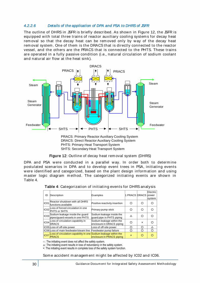
The outline of DHRS in JSFR is briefly described. As shown in Figure 12, the JSFR is equipped with total three trains of reactor auxiliary cooling systems for decay heat removal so that the decay heat can be removed only by way of the decay heat removal system. One of them is the DRACS that is directly connected to the reactor vessel, and the others are the PRACS that is connected to the PHTS. These trains are operated in a fully passive condition (i.e., natural circulation of sodium coolant and natural air flow at the heat sink).
PRACS: Primary Reactor Auxiliary Cooling System
DRACS: Direct Reactor Auxiliary Cooling System
PHTS: Primary Heat Transport System
SHTS: Secondary Heat Transport System
PRACS
Steam
Generator
DRACS
Steam
Feedwater
PRACS
Steam
Steam
Generator
Feedwater
PHTSSHTS SHTS
Figure 12: Outline of decay heat removal system (DHRS)
DPA and PSA were conducted in a parallel way. In order both to determine postulated scenarios in DPA and to develop event trees in PSA, initiating events were identified and categorized, based on the plant design information and using master logic diagram method. The categorized initiating events are shown in Table 4.
Table 4: Categorization of initiating events for DHRS analysis
ID Description Examples 1 PRACS DRACS
Electric
power
system
IC01Reactor shutdown with all DHRS
functions availablePositive reactivity insertion ○ ○ ○
IC02Loss of forced circulation in one
PHTS or SHTSPrimary pump stick ○ ○ ○
IC03Sodium leakage inside the guard
pipes/guard vessels in one PHTS
Sodium leakage inside the
guard pipe in PHTS piping△ ○ ○
IC04Loss of circulation capability in
DRACS
Sodium leakage within the
enclosure in DRACS piping○ × ○
IC05 Loss of off-site power Loss of off-site power ○ ○ △
IC06 Loss of main feedwater/steam line Feedwater pump failure ○ ○ ○
IC07Loss of circulation capability in one
PRACS
Sodium leakage within the
enclosure in PRACS piping× ○ ○
○: The initiating event does not affect the safety system. △: The initiating event results in loss of redundancy in the safety system. ×: The initiating event results in complete loss of the safety system function.
Some accident management might be affected by IC02 and IC06.
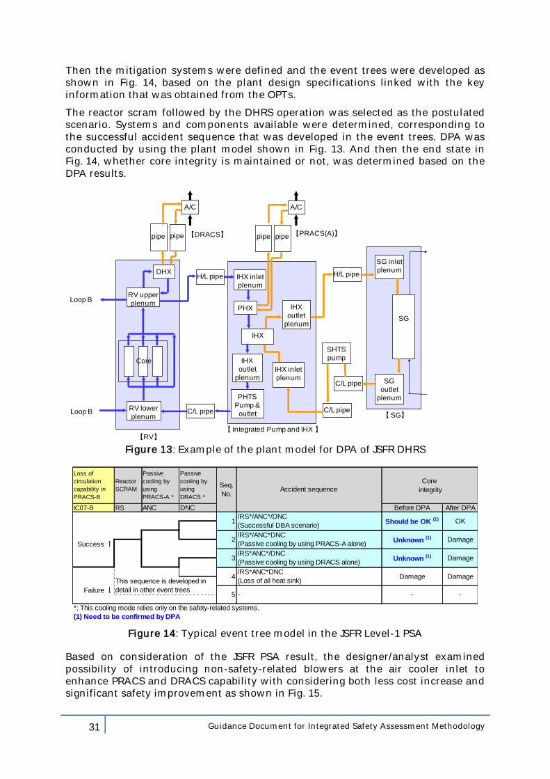
31 Guidance Document for Integrated Safety Assessment Methodology
Then the mitigation systems were defined and the event trees were developed as shown in Fig. 14, based on the plant design specifications linked with the key information that was obtained from the OPTs.
The reactor scram followed by the DHRS operation was selected as the postulated scenario. Systems and components available were determined, corresponding to the successful accident sequence that was developed in the event trees. DPA was conducted by using the plant model shown in Fig. 13. And then the end state in Fig. 14, whether core integrity is maintained or not, was determined based on the DPA results.
pipe
DHX
RV upper
plenum
H/L pipe IHX inlet
plenum
IHX
PHTS
Pump &
outlet
IHX
outlet
plenumIHX inlet
plenum
C/L pipeRV lower
plenum
Core
IHX
outlet
plenum
C/L pipe
C/L pipe
H/L pipe
SG
PHX
SG inlet
plenum
SG
outlet
plenum
A/C
【RV】
【DRACS】 【PRACS(A)】
A/C
Loop B
【SG】
SHTS
pump
【 Integrated Pump and IHX 】
Loop B
pipe pipe pipe
Figure 13: Example of the plant model for DPA of JSFR DHRS
Loss of
circulation
capability in
PRACS-B
Reactor
SCRAM
Passive
cooling by
using
PRACS-A *
Passive
cooling by
using
DRACS *
IC07-B RS ANC DNC Before DPA After DPA
Success ↑
Failure ↓
OK
Damage
Damage
Damage
-
Core
integritySeq.
No.Accident sequence
1/RS*/ANC*/DNC
(Successful DBA scenario)Should be OK (1)
/RS*/ANC*DNC
(Passive cooling by using PRACS-A alone)Unknown (1)
3/RS*ANC*/DNC
(Passive cooling by using DRACS alone)Unknown (1)
(1) Need to be confirmed by DPA
*; This cooling mode relies only on the safety-related systems.
2
This sequence is developed in
detail in other event trees5 - -
4/RS*ANC*DNC
(Loss of all heat sink)Damage
Figure 14: Typical event tree model in the JSFR Level-1 PSA
Based on consideration of the JSFR PSA result, the designer/analyst examined possibility of introducing non-safety-related blowers at the air cooler inlet to enhance PRACS and DRACS capability with considering both less cost increase and significant safety improvement as shown in Fig. 15.
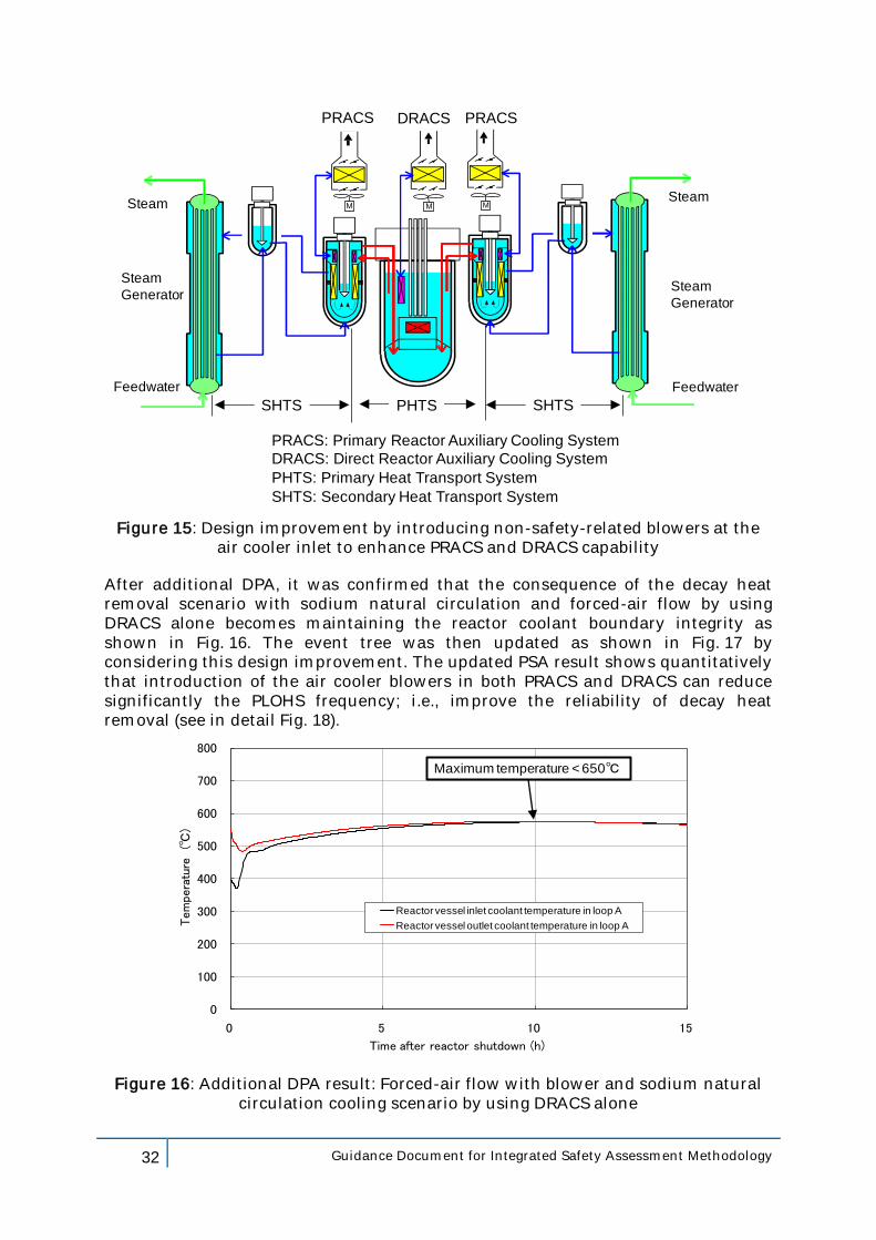
32 Guidance Document for Integrated Safety Assessment Methodology
PRACS: Primary Reactor Auxiliary Cooling System
DRACS: Direct Reactor Auxiliary Cooling System
PHTS: Primary Heat Transport System
SHTS: Secondary Heat Transport System
PRACS
Steam
Generator
DRACS
Steam
Feedwater
PRACS
Steam
Steam
Generator
Feedwater
PHTSSHTS SHTS
M M M
Figure 15: Design improvement by introducing non-safety-related blowers at the air cooler inlet to enhance PRACS and DRACS capability
After additional DPA, it was confirmed that the consequence of the decay heat removal scenario with sodium natural circulation and forced-air flow by using DRACS alone becomes maintaining the reactor coolant boundary integrity as shown in Fig. 16. The event tree was then updated as shown in Fig. 17 by considering this design improvement. The updated PSA result shows quantitatively that introduction of the air cooler blowers in both PRACS and DRACS can reduce significantly the PLOHS frequency; i.e., improve the reliability of decay heat removal (see in detail Fig. 18).
0
100
200
300
400
500
600
700
800
0 5 10 15
Tem
pera
ture
(℃)
Time after reactor shutdown (h)
Reactor vessel inlet coolant temperature in loop A
Reactor vessel outlet coolant temperature in loop A
Maximum temperature < 650℃
Figure 16: Additional DPA result: Forced-air flow with blower and sodium natural circulation cooling scenario by using DRACS alone
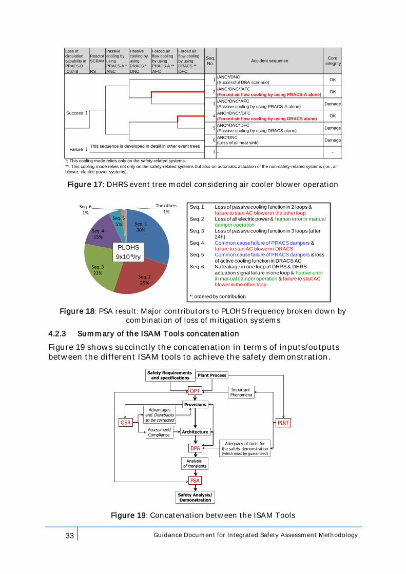
33 Guidance Document for Integrated Safety Assessment Methodology
Loss of
circulation
capability in
PRACS-B
Reactor
SCRAM
Passive
cooling by
using
PRACS-A *
Passive
cooling by
using
DRACS *
Forced air
flow cooling
by using
PRACS-A **
Forced air
flow cooling
by using
DRACS **
IC07-B RS ANC DNC AFC DFC
Success ↑
Failure ↓
*; This cooling mode relies only on the safety-related systems.
**; This cooling mode relies not only on the safety-related systems but also on automatic actuation of the non-safety-related systems (i.e., air
blower, electric power systems).
This sequence is developed in detail in other event trees
6ANC*DNC
(Loss of all heat sink)Damage
7 - -
4ANC*/DNC*/DFC
(Forced air flow cooling by using DRACS alone)OK
5ANC*/DNC*DFC
(Passive cooling by using DRACS alone)Damage
2/ANC*DNC*/AFC
(Forced air flow cooling by using PRACS-A alone)OK
3/ANC*DNC*AFC
(Passive cooling by using PRACS-A alone)Damage
Seq.
No.Accident sequence
Core
integrity
1/ANC*/DNC
(Successful DBA scenario)OK
Figure 17: DHRS event tree model considering air cooler blower operation
Seq. 130%
Seq. 225%
Seq. 323%
Seq. 415%
Seq. 55%
Seq. 61%
The others1%
PLOHS
9x10⁻⁹/ry
Seq. 1 Loss of passive cooling function in 2 loops &
failure to start AC blower in the other loopSeq. 2 Loss of all electric power & human error in manual
damper operation
Seq. 3 Loss of passive cooling function in 3 loops (after 24h)
Seq. 4 Common cause failure of PRACS dampers & failure to start AC blower in DRACS
Seq. 5 Common cause failure of PRACS dampers & loss
of active cooling function in DRACS ACSeq. 6 Na leakage in one loop of DHRS & DHRS
actuation signal failure in one loop & human error in manual damper operation & failure to start AC blower in the other loop
*; ordered by contribution
Figure 18: PSA result: Major contributors to PLOHS frequency broken down by combination of loss of mitigation systems
4.2.3 Summary of the ISAM Tools concatenation
Figure 19 shows succinctly the concatenation in terms of inputs/outputs between the different ISAM tools to achieve the safety demonstration.
Important Phenomena
Provisions
Architecture
Adequacy of tools forthe safety demonstration(which must be guaranteed)
Safety Analysis/Demonstration
Assessment/Compliance
QSR PIRT
OPT
DPA
PSA
Safety Requirementsand specifications
Advantagesand Drawbacksto be corrected
Analysisof transients
Plant Process
Figure 19: Concatenation between the ISAM Tools
34 Guidance Document for Integrated Safety Assessment Methodology
5. Conclusions
A key objective oWorking Group charter is the development and the qualification of an integrated methodology that can be used to evaluate and document the safety of Gen IV nuclear systems.
Coherently with its mandate, RSWG prepared and delivered in 2011 a document that describes the Integrated Safety Assessment Methodology (ISAM), for use throughout the Gen IV technology development cycle.
The methodology has been presented to the different Gen IV System Steering Committees during a specific workshop organized in April 2010 in JRC/Petten. Following the workshop comments and suggestions were collected.
Among these comments and suggestions there are the explicit need for having a more detailed description/justification about the "integration" of the different ISAM tools, as well as the request for further practical guidelines for its application.
To answer this request as part of facilitating the use of the methodology, the RSWG identified the need to develop a supporting Guidance Document for ISAM (GDI) to provide the users with further help for the ISAM implementation.
This DGI was developed to meet the following objectives:
1) To provide a step-by-step description on how to apply ISAM:
a) to identify the inputs and outputs of the different tools; b) to explain the flow from one step to another; c) to elaborate a flow chart in support.
2) To illustrate a pilot application of ISAM to a specific system or part of system as an example.
The following topics were addressed by the GDI document:
• The proof of consistency/adequacy between on one side the ISAM tools and structure and, on the other side, the current requirements and recommendations applicable to future nuclear systems;
• A summary of ISAM describing, for the different tools:
– the inputs and outputs; – their mutual dependencies.
• The precise definition of the possible role and contribution of each ISAM tool versus the different plant design status (pre-conceptual, conceptual, final; i.e. the step-by-step application of ISAM). It is proposed that either the single case of a given design status (e.g. conceptual design) is considered with the application of the five tools or several distinctive combinations of some of the five tools are analysed.
In this paper the different ISAM tools are discussed singularly and globally to outline their respective role within the context of the whole design and assessment process. Flowchart for their concatenation is provided.
Specific studies were performed in parallel (on QSR, the OPT/LOP, the whole ISAM), to reinforce the relevance of both singular tools and methodology as a whole, vis-à-vis of available and applicable recommendations for future reactors.

35 Guidance Document for Integrated Safety Assessment Methodology
Examples of applications are presented; they treat both the case of completely innovative concepts that are proposed for integration into future concepts (e.g. the stratified Redan for future pool type SFR, analyzed with the QSR, the PIRT, the OPT and the DPA) or systems already integrated into projects fourth generation (JSFR with overall OPT, the JSFR Self Actuated Shut Down Systems (SSAS) with the PIRT, the Decay Heat Removal Systems JSFR (DHRS) with the DPA and the PSA).
All these examples should convince the designers about the relevance and usefulness of the ISAM method and its tools to help make up the design and the assessment of systems or components, as well as overall architectures, for fourth generation systems.
36 Guidance Document for Integrated Safety Assessment Methodology
6. References
1) GIF/RSWG/2007/002 Basis for the Safety Approach for Design & Assessment of Generation IV Nuclear Systems; Revision 1 (November 24, 2008).
2) GIF/RSWG/2010/002/Rev.1 An Integrated Safety Assessment Methodology (ISAM)for Generation IV Nuclear Systems (June 2011).
3) G. L. Fiorini, A guidance document for Integrated Safety Assessment Methodology for use throughout the Gen IV technology development cycle, Service Contract N° JRC.BXL.C1 82040, Brussels (2010).
4) IAEA, Safety Assessment and Verification for Nuclear Power Plants; Safety Guide No. NS-G-1.2 ; Vienna (2001).
5) IAEA, Safety of Nuclear Power Plants: Design ; Specific Safety Requirements No. SSR-2.1 ; Vienna (2012).
6) G. L. Fiorini; N. Hakimi; B. Tombuyses; C. Dams, A. Wertelaers, M. Schrauben, R. Dresselaers: The Design Options and Provision File and the role of the defence in depth within the pre-licensing of the MYRRHA project. International Conference on Topical Issues in Nuclear Installation Safety: Defence in Depth Advances and Challenges for Nuclear Installation Safety; IAEA Headquarters, Vienna, Austria (21 24 October 2013).
7) IAEA, Fundamental Safety Principles Series No. SF-1 (2006).
8) Safety of new NPP designs Study by WENRA Reactor Harmonization Working Group; October 2012 Draft N°9.
9) WENRA Statement on Safety Objectives for New Nuclear Plants (November 2010).
10) IAEA The safety of Nuclear Installation Safety series N°110.
11) IAEA-TECDOC-682, Objectives for the development of advanced nuclear plants.
12) IAEA-TECDOC-626, Safety related terms for advanced nuclear plants.
13) IAEA-TECDOC-1624, Passive Safety Systems and Natural Circulation in Water Cooled Nuclear Power Plants (November 2009).
14) IAEA Safety Glossary, Terminology Used in Nuclear Safety and Radiation Protection, 2007 Edition.
15) IAEA-NS-R4 Safety of Research Reactors (2005).
16) WENRA Reactor Safety Reference Levels (January 2008).
17) International Project on Innovative Nuclear Reactors and Fuel Cycles (INPRO): Guidance for the Application of an Assessment Methodology for Innovative Nuclear Energy Systems INPRO Manual Overview of the Methodology IAEA-TECDOC-1575 Rev. 1 (November 2008).
18) G. L. Fiorini: Analysis of the INPRO methodology concerning the safety assessment. Critical comparison with the status of the RSWG requirements and tool (QSR) Crosscut and direct comparison; RSWG QSR/INPRO (08/10/09).
19) G. L. Fiorini: Analysis of the IAEA NSSR-2/1document concerning the Safety of Nuclear Power Plants: Design. Critical comparison with the status of the
37 Guidance Document for Integrated Safety Assessment Methodology
RSWG-Qualitative Safety Review (QSR) set of criteria Crosscut and direct comparison; RSWG QSR/NSSR 2-1 (08/10/2012).
20) L. Ammirabile, European project SARGEN_IV: safety approach and assessment of GEN IV reactors, 3rd Joint GIF-IAEA Workshop on Safety Design Criteria for Sodium-Cooled Fast Reactors, Vienna (Feb 2013).
21) Tim Leahy Probabilistic Safety Assessment (PSA) as an Element of the Gen IV ISAM RSWG/SSC Workshop, 12-13 April 2010, Petten, the Netherlands.
22) Guy-Marie Gautier & Al: SFR innovative design: the Stratified Redan Concept; CEA, DEN, DER, CEN Cadarache Proceedings of ICAPP 2011 Nice, France, May 2-5, 2011 Paper 11165.
23) G. L. Fiorini: Applicability of the RSWG/ISAM to an SFR Innovative Concept: the Stratified REDAN Qualitative Safety Review (ISAM/QSR); CEA/DEN/CAD/DER/SESI/DIR/NT DO 8 13/12/10 Indice 0.
24) G. L. Fiorini: Applicability of the RSWG/ISAM to an SFR Innovative Concept: the Stratified REDAN Phenomena Identification Ranking Table (ISAM/PIRT); 1a Three case studies CEA/DEN/CAD/DER/SESI/DIR/NT DO 09; 13/12/10 Indice 0.
25) G. L. Fiorini: Applicability of the RSWG/ISAM to an SFR Innovative Concept: the Stratified REDAN Phenomena Identification Ranking Table (ISAM/PIRT); 1b One case study CEA/DEN/CAD/DER/SESI/DIR/NT DO 10; 13/12/10 Indice 0.
26) Considerations in the development of safety requirements for innovative reactors: Application to modular high temperature gas cooled reactors; IAEA Tecdoc 1366 (August 2003).
27) Assessment of Defence in Depth for Nuclear Power Plants; IAEA Safety Report Series No. 46, (February 2005).
28) -Type Fast Reactor in
(June 8-12, 2008).
29) -Type Fast Reactor in Japan (5): Adoption of Self-
(June 8-12, 2008).
30) -Cooled Fast Reactor Concept and -186 (2007).
31) WENRA Safety of New NPP designs (2013).
38 Guidance Document for Integrated Safety Assessment Methodology
Appendix 1. The glossary of the flowchart (cf. Fig.2)
N.B. Terms are presented in alphabetical order
Challenges
generalized mechanisms, processes or circumstances (conditions) that may impact the intended performance of safety functions; a set of which mechanisms have consequences which are similar in nature .
Controlled state
Cf. Ref. 5 Plant state, following an anticipated operational occurrence or accident conditions, in which the fundamental safety functions can be ensured and which can be maintained for a time sufficient to implement provisions to reach a safe sta
SSCs Design Criteria
SSCs design criteria (or decoupling criteria) are physical parameters (e.g. number of clad failures) which make the link between the safety objectives, which are formulated in quite generic manner (e.g. health consequences corresponding releases), and quantitative and measurable objectives or acceptance criteria (e.g. maximum clad temperature) which are usable by the designer to check the acceptability of the design. Moreover, through the assessment process, they allow defining measurable safety margins.
Design and Operational Safety Specifications
Two types of specifications can be considered under this term.
y the need to execute the tasks requested to ensure the achievement of safety functions and the compliance with safety objectives. These design specifications are essential for the design and sizing of the provisions of the safety architecture; these design specifications relate to both physical performances and reliability requested in cases of solicitation.
with specific rules for operation as well as for In Service Inspection and Repair and maintenance, and that ensure that the plant is kept its design domain.
Mechanism
Specific reasons, processes or situations whose consequences might create challenges to the performance of safety functions . Versus the safety functions, the mechanism(s) materialize the challenge.
Mission
The safety mission is the set of actions achieved by the safety architecture and its provisions (including procedures) to bring the plant into a controlled state.
39 Guidance Document for Integrated Safety Assessment Methodology
Provisions
integral part of the safety architecture.
Prevention, control and mitigation of incident and accidents are managed by technical provisions and/or organizational measures (i.e. the safety architecture, the security architecture). Technical safety provisions include: structures (buildings, concrete shell, skates earthquake, etc.), active and/or passive systems (cooling, control/surveillance, detection, alarm, etc..), components (pumps, pools, valves, etc.) which can be grouped under the term "systems, structures and
characteristics such as the counter reactions, the thermal inertia, etc.
The operational provisions include: operating rules; technical specifications; in-service inspection; normal, incident and accident procedures; the organization of crisis intervention.
As indicated above all these provisions have to be designed and set up within the safety architecture.
Safety Architecture
The notion of "Final design" (cf. Fig. 4)
to carry out the missions of the installation (e.g. energy production).
The safety architecture shall allow getting close to the safety goals, ensuring that
accidental. Within the context of this document the notion of safety architecture should be considered generic; in practice it is characterized by all the "technical provisions" (including inherent physical characteristics) and organizational measures for the design, the construction, the operation, the shutdown and the decommissioning of a facility, taken to prevent abnormal or degraded situations or limit their effects.
Following this definition, any "technical or organizational provision" involved in the realization of the safety is an integral part of this architecture. So this notion of "safety architecture" aims at:
• assisting in the identification of all the provisions that contribute to make (i.e. the plant into a controlled state) and
therefore to control the risk;
• facilitating the design and sizing of the provisions by including in their specifications both functional goals, objectives and reliability constraints generated by any other provisions of the environment, in which they are required to achieve their mission.
Safety Goals
The safety goals for the GEN IV systems are defined by the Technology Roadmap (Ref. 8) and the designer should use these goals to define Safety Objectives and to justify the priority given to certain subjects of R & D that support the design.
Indeed, the goals are defined (cf. Ref.1):nuclear energy systems both for the reactors and the fuel cycle installations and it will serve to motivate and guide the R&D on Generation IV systems as collaborative efforts get
40 Guidance Document for Integrated Safety Assessment Methodology
Safety Guidelines
The setting of the design is also accompanied by the choice by the designer of guidelines that underlines the design process. Among the nuclear safety standards, the IAEA safety guides shall be considered as the first options when compared to alternative guidance documents (e.g. Ref. 4); they provide recommendations and guidance on how to comply with the IAEA safety requirements, indicating an international consensus on the measures recommended. In that context, general and specific IAEA safety guides standards shall be considered by the designer as the first option when compared to alternative guidance, taking into account the specificity of installation under consideration.
Other complementary guidelines can be selected if they reflect best practices used by the nuclear technology and/or are supported by a significant feedback experience.
Safety Objectives
Starting from the "Goals", and the minimum safety objectives (e.g. WENRA, Ref. 9),
translation of the goals into the objectives adopted for the design, starts from the Fundamental Safety Objective indicated by the IAEA, as well as by the two corollary objectives concerning Radiation Protection Objective and Technical Safety Objective (Ref. 10).
In general the safety objectives are defined in a relative manner comparing to what is achieved, for example, by the installations in operation. Other complementary objectives can be defined by the designer if considered necessary13, both to inform the design and/or to make the safety approach more explicit/efficient.
For the purpose of the design, it is necessary to break down the qualitative safety objectives into quantitative safety objectives and technical criteria (decoupling criteria) so that the designer can verify that they are achieved. For that it is important to quantify these criteria for example by indicating a specific link with the basic safety functions (reactivity control, energy removal, confinement) and/or, if necessary, with sub-functions.
Moreover considering the installation conditions (normal, incidental, accidental) specific targets should be defined for each these conditions, for example for the different levels of the defense in depth (e.g. using a Farmer curve).
Safety Options
The selection of provisions to build the safety architecture is not necessarily a unique process: several design solutions are often available, all of which are formally able to achieve the safety objectives.
In these conditions, other criteria may be considered by the designer to select the right provisions such as the economy, ease of operation or maintenance, availability or absence of a significant feedback experience, etc.. One can note that these criteria should not necessarily be the same for the entire installation, each provision or group of provisions may justify the selection of specific safety options.
Thus the simultaneous consideration, on one side, of the safety objectives and principles and guidelines and, on the other hand, of these other additional criteria, lead to the definition of "safety options" for the selection and the detailed
13 For example to improve the robustness of the demonstration.
41 Guidance Document for Integrated Safety Assessment Methodology
organization of provisions that build up the safety architecture. For example, the selection between active or passive operation, static and dynamic behaviour of a barrier, the degree of easiness and ability to repair or replace a defective component, are all design safety option that the designer should define before selecting and sizing the provision(s) which will realize the safety function.
Once more it is worth noting that the design safety option is not the implemented solution itself but the way (i.e. the design strategy) to perform the mission required to meet the objective(s) of the safety function(s); it affects the search, the selection and the sizing of the provision(s) that materialize the implemented solution and achieve the requested mission.
The justification that these options allow getting close to the safety goals and meeting the safety objectives shall be presented. The available design basis documentation and knowledge, the R&D topics which are under assessment as well as the open safety issues, should also be addressed to justify the selected safety options.
Safety Principles
The setting of objectives for the design is accompanied by the choice by the designer, of principles that underlines the design process. Ten fundamental and mandatory safety principles are defined within the Ref.7. Other complementary principles (see Appendix 2) can be selected by the designer to provide the needed inputs to define the safety options, e.g.:
1. Performing the safety functions incorporating into the design an appropriate combination of inherent safety features, safety systems and engineered safety features active and passive
2. Defense in depth for accident prevention, control and mitigation
3. Risk-Informed Design, Simulation and Prototyping
4. Etc.
Safety Requirements
Safety requirements define the elements necessary to ensure nuclear safety (e.g. Ref. 5 and Appendix 3); they are applicable to the safety functions and to the associated provisions: structures, systems and components, as well as to procedures important to the safety of the installation.
Safety requirements address design and operation of the installation and are needed to define safety options.
42 Guidance Document for Integrated Safety Assessment Methodology
Appendix 2. Safety design principles
The fundamental principles presented within the Ref. 7; they address the following themes:
Principle 1: Responsibility for safety
Principle 2: Role of government
Principle 3: Leadership and management for safety
Principle 4: Justification of facilities and activities
Principle 5: Optimization of protection
Principle 6: Limitation of risks to individuals
Principle 7: Protection of present and future generations
Principle 8: Prevention of accidents
Principle 9: Emergency preparedness and response
Principle 10: Protective actions to reduce existing or unregulated radiation risks
Beside these principles a non-exhaustive list of specific safety principles felt to be particularly relevant for design are presented next.
1) Taking advantage of inherent safety characteristics, utilizing passive safety systems
Inherent safety characteristics: Referring to Ref. 11, an inherent safety characteristic provides assurance of the elimination of a potential internal hazard to the safety of the nuclear plant. Hence, the plant design should seek to take maximum, feasible advantage of inherent safety characteristics through selection of materials, their quantity, their physical properties and their configuration in the plant design, to the extent that these characteristics have been proven to provide enhanced safety. Providing, for example, negative reactivity insertion to assure shutdown, through adequate core negative reactivity effect, appears to be a function amenable to the use of inherent safety characteristic.
Passive safety system: Throughout the IAEA publications, different definitions of passive systems can be found. Referring to Ref. 12 a passive safety system provides a safety related function without reliance on operator action and on external mechanical and/or electrical power, signals or applied forces. A passive safety system, when initiated, relies instead on natural forces such as natural convection, heat conduction and heat radiation, on inherent safety characteristics and on internally stored energy. Referring to appendix A of Ref. 12 and Ref. 13, there exist different levels of passiveness for the design of safety systems depending on the startup mechanism of the system and/or the physical processes involved in its operation (e.g. inherent safety by negative reactivity feedback from the transient is an example of the highest level of passiveness)14. More simply, referring to the IAEA safety glossary (Ref. 14), a passive component is a component whose functioning does not depend on an external input such as actuation, mechanical movement or supply of power. Regardless of the definition adopted for passive systems or their classification, the reliability of any passive system, active system or combined passive/active system should be evaluated. Efforts should be made to utilize reliable passive safety systems in the plant, especially for accidental conditions. Providing, for example, adequate rate and magnitude of negative reactivity insertion to assure
14 In practice this classification is no longer used.
43 Guidance Document for Integrated Safety Assessment Methodology
shutdown and providing adequate thermal inertia and/or the possibility for natural convection to limit temperatures of the fuel, components, systems and structures appear to be functions amenable to the use of passive systems.
2) Performing the safety functions
Referring to Ref. 15, the three basic safety functions essentially, controlling the core reactivity, cooling in particular the reactor core and the spent fuel, and confining radioactive material shall be met by incorporating into the design an appropriate combination of inherent safety features, safety systems and engineered safety features active and passive, the objective being to be successful in efficiency, reliability15 and availability.
3) Defense in depth for accident prevention, control and mitigation
Defense in depth is the primary means to address the fundamental safety principles 5 to 9 (Optimization of protection; Limitation of risks to individuals; Protection of present and future generations; Prevention of accidents; & Emergency preparedness and response) (cf. Ref. 7), i.e. the primary means of preventing, controlling and mitigating the consequences of accidents. Defense in depth is implemented primarily through the combination of a number of consecutive and independent levels of protection that would have to fail before harmful effects could be caused to people or to the environment. If one level of protection or barrier were to fail, the subsequent level or barrier would be available. When properly implemented, defense in depth ensures that no single technical, human or organizational failure could lead to harmful effects, and that the combinations of failures that could give rise to significant harmful effects are of very low probability. The effectiveness of the independency between the different levels16 of defense is a necessary element of defense in depth.
As far as the design is concerned, defense in depth is provided by an appropriate combination of:
The incorporation of good design and engineering features which provide safety margins, diversity and redundancy, mainly by the use of:
– Design, technology and materials of high quality and reliability;
– Control, limiting and protection systems and surveillance features;
– An appropriate combination of inherent and engineered safety features (active and/or passive).
An effective management system with a strong management commitment to safety and a strong safety culture for all the actors throughout the whole life of the installation (design, construction, operation and dismantling).
An adequate site selection to minimize the risk for external hazards
As stated in Ref.1, the emphasis should be on prevention backed up by mitigation, meaning that th will result in further improvements in reactor safety rather than on achieving a significant reduction in a selected fundamental risk metric. For example, it may be more desirable to effectively eliminate
15 The correct assessment of efficiency and reliability of implemented measures is a key issue to
justify the selection of design options and corresponding provisions. This applies to all sort of provisions, namely the inherent characteristics, as well as to active or passive engineered systems.
16 The failure of a given level of the DiD, i.e. the failure of the corresponding provisions, does not affect the efficiency and the reliability of the following level.
44 Guidance Document for Integrated Safety Assessment Methodology
accident sequences that might have the potential for offsite releases of radionuclides than it is to make substantial improvements in containment performance
4) Risk-Informed Design, Simulation and Prototyping
Risk-Informed17 Design, Simulation, Prototyping are principles more and more referred to and taken on board as principles in the design the reactors of the future (Ref.1).
17 Risk Informed design, i.e.: deterministic approach complemented by probabilistic methods.
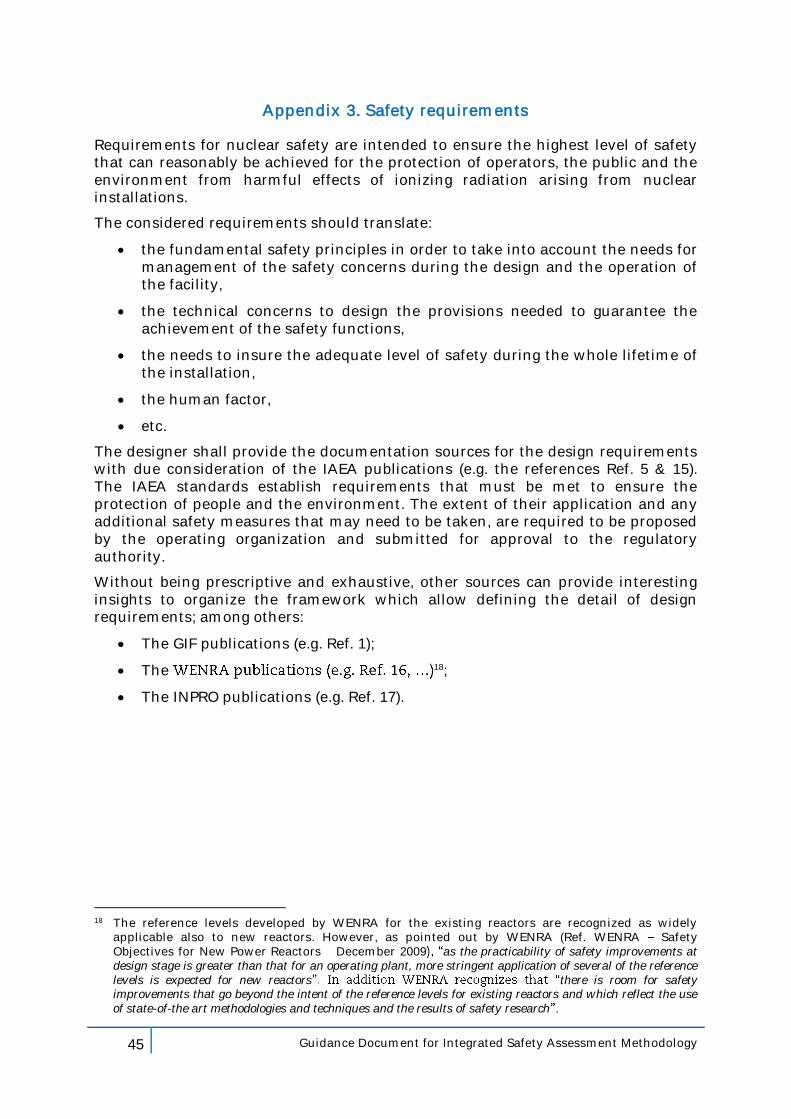
45 Guidance Document for Integrated Safety Assessment Methodology
Appendix 3. Safety requirements
Requirements for nuclear safety are intended to ensure the highest level of safety that can reasonably be achieved for the protection of operators, the public and the environment from harmful effects of ionizing radiation arising from nuclear installations.
The considered requirements should translate:
the fundamental safety principles in order to take into account the needs for management of the safety concerns during the design and the operation of the facility,
the technical concerns to design the provisions needed to guarantee the achievement of the safety functions,
the needs to insure the adequate level of safety during the whole lifetime of the installation,
the human factor,
etc.
The designer shall provide the documentation sources for the design requirements with due consideration of the IAEA publications (e.g. the references Ref. 5 & 15). The IAEA standards establish requirements that must be met to ensure the protection of people and the environment. The extent of their application and any additional safety measures that may need to be taken, are required to be proposed by the operating organization and submitted for approval to the regulatory authority.
Without being prescriptive and exhaustive, other sources can provide interesting insights to organize the framework which allow defining the detail of design requirements; among others:
The GIF publications (e.g. Ref. 1);
The 18;
The INPRO publications (e.g. Ref. 17).
18 The reference levels developed by WENRA for the existing reactors are recognized as widely
applicable also to new reactors. However, as pointed out by WENRA (Ref. WENRA Safety Objectives for New Power Reactors December 2009 as the practicability of safety improvements at design stage is greater than that for an operating plant, more stringent application of several of the reference levels is expected for new reactors there is room for safety improvements that go beyond the intent of the reference levels for existing reactors and which reflect the use of state-of-the art methodologies and techniques and the results of safety research .
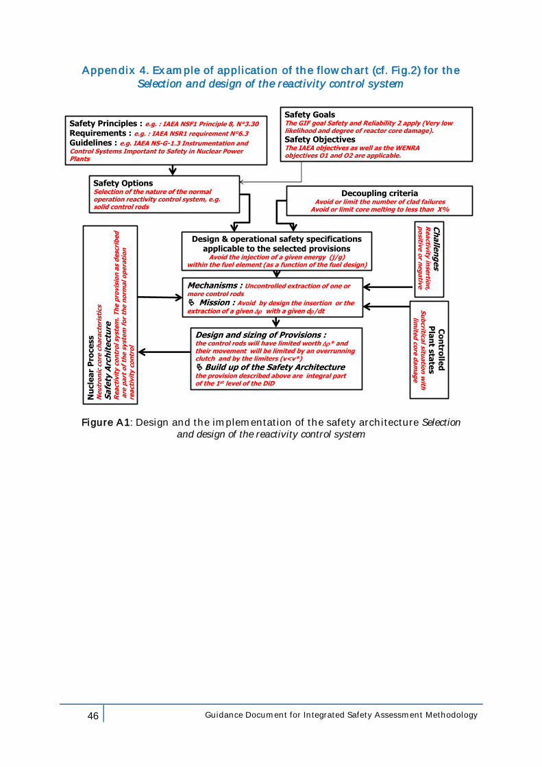
46 Guidance Document for Integrated Safety Assessment Methodology
Appendix 4. Example of application of the flowchart (cf. Fig.2) for the Selection and design of the reactivity control system
Safety Goals The GIF goal Safety and Reliability 2 apply (Very low likelihood and degree of reactor core damage).
Safety Objectives The IAEA objectives as well as the WENRA objectives O1 and O2 are applicable.
Design & operational safety specificationsapplicable to the selected provisions
Avoid the injection of a given energy (j/g)within the fuel element (as a function of the fuel design)
Safety Options Selection of the nature of the normal operation reactivity control system, e.g. solid control rods
Design and sizing of Provisions : the control rods will have limited worth * and their movement will be limited by an overrunning clutch and by the limiters (v<v*)
Build up of the Safety Architecturethe provision described above are integral part of the 1st level of the DiD
Safety Principles : e.g. : IAEA NSF1 Principle 8, N°3.30
Requirements : e.g. : IAEA NSR1 requirement N°6.3
Guidelines : e.g. IAEA NS-G-1.3 Instrumentation and Control Systems Important to Safety in Nuclear Power Plants
Decoupling criteriaAvoid or limit the number of clad failures
Avoid or limit core melting to less than X%
Nu
cle
ar
Pro
ce
ss
Ne
utr
on
icco
re c
ha
racte
rist
ics
Sa
fety
Arc
hit
ectu
reR
ea
cti
vit
y c
on
tro
l sy
ste
m.
Th
e p
rovis
ion
as
de
scri
be
da
re p
art
of
the
syst
em
fo
r th
e n
orm
al o
pe
rati
on
re
acti
vit
y c
on
tro
l
Co
ntro
lled
Pla
nt s
tate
sS
ub
critic
al situ
atio
n w
ith
limite
d c
ore
da
ma
ge
Mechanisms : Uncontrolled extraction of one or more control rods
Mission : Avoid by design the insertion or the extraction of a given with a given d/dt
Ch
alle
ng
es
Re
activ
ityin
sertio
n,
po
sitive
or n
eg
ativ
e
Figure A1: Design and the implementation of the safety architecture Selection and design of the reactivity control system
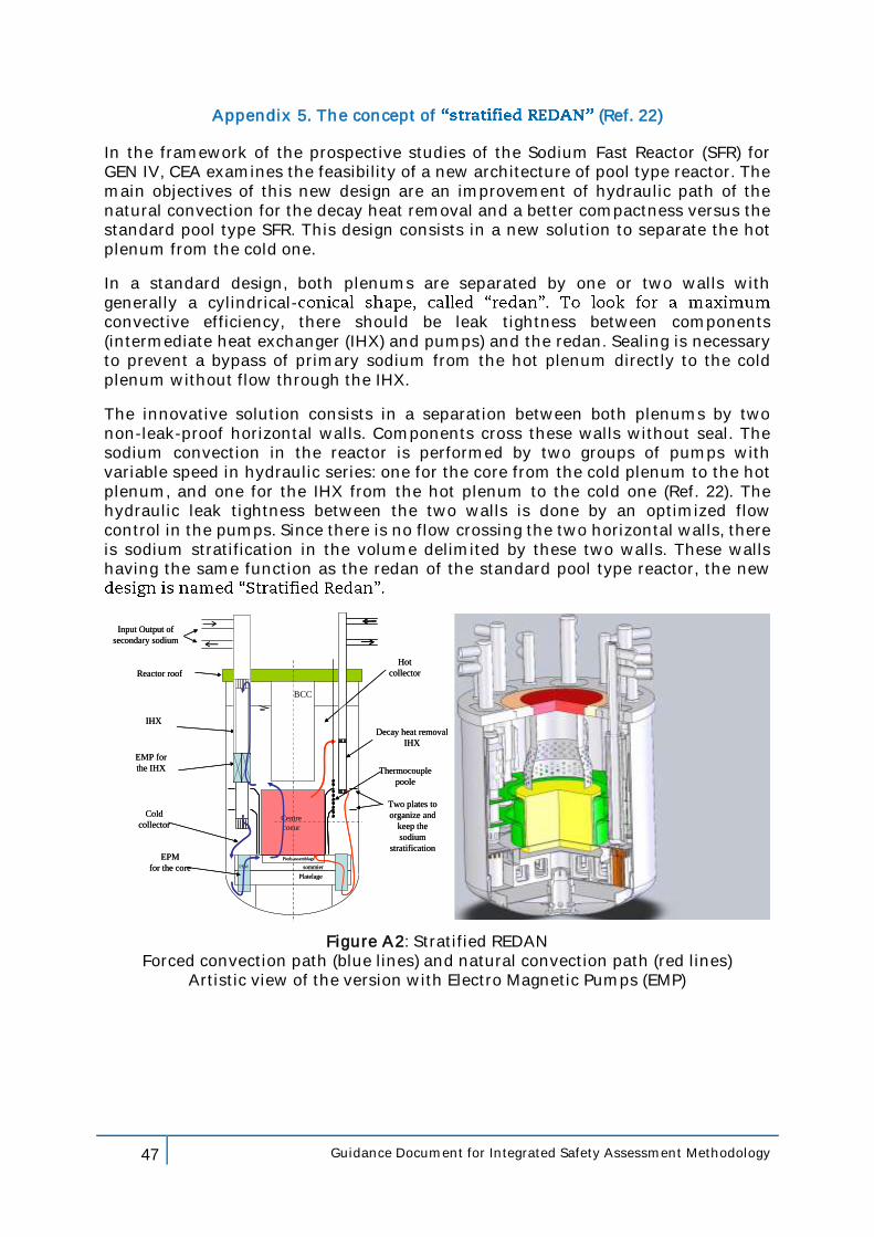
47 Guidance Document for Integrated Safety Assessment Methodology
Appendix 5. The concept of (Ref. 22)
In the framework of the prospective studies of the Sodium Fast Reactor (SFR) for GEN IV, CEA examines the feasibility of a new architecture of pool type reactor. The main objectives of this new design are an improvement of hydraulic path of the natural convection for the decay heat removal and a better compactness versus the standard pool type SFR. This design consists in a new solution to separate the hot plenum from the cold one.
In a standard design, both plenums are separated by one or two walls with generally a cylindrical-convective efficiency, there should be leak tightness between components (intermediate heat exchanger (IHX) and pumps) and the redan. Sealing is necessary to prevent a bypass of primary sodium from the hot plenum directly to the cold plenum without flow through the IHX.
The innovative solution consists in a separation between both plenums by two non-leak-proof horizontal walls. Components cross these walls without seal. The sodium convection in the reactor is performed by two groups of pumps with variable speed in hydraulic series: one for the core from the cold plenum to the hot plenum, and one for the IHX from the hot plenum to the cold one (Ref. 22). The hydraulic leak tightness between the two walls is done by an optimized flow control in the pumps. Since there is no flow crossing the two horizontal walls, there is sodium stratification in the volume delimited by these two walls. These walls having the same function as the redan of the standard pool type reactor, the new
Pieds assemblage
Centre
coeur
sommier
Platelage
PEM
IHX
EMP for
the IHX
EPM
for the core
Two plates to
organize and
keep the
sodium
stratification
Decay heat removal
IHX
BCC
Hot
collector
Cold
collector
Input Output of
secondary sodium
Reactor roof
Thermocouple
poole
Pieds assemblage
Centre
coeur
sommier
Platelage
PEM
IHX
EMP for
the IHX
EPM
for the core
Two plates to
organize and
keep the
sodium
stratification
Decay heat removal
IHX
BCC
Hot
collector
Cold
collector
Input Output of
secondary sodium
Reactor roof
Thermocouple
poole
Figure A2: Stratified REDAN Forced convection path (blue lines) and natural convection path (red lines)
Artistic view of the version with Electro Magnetic Pumps (EMP)
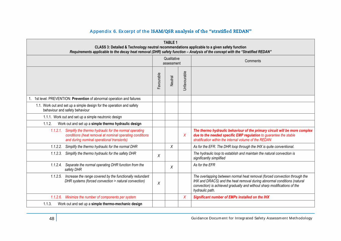
48 Guidance Document for Integrated Safety Assessment Methodology
Appendix 6. Excerpt of the
TABLE 1 CLASS 3: Detailed & Technology neutral recommendations applicable to a given safety function
Requirements applicable to the decay heat removal (DHR) safety function – Analysis of the concept with the “Stratified REDAN”
Qualitative
assessment Comments
Fav
oura
ble
Neu
tral
Unf
avou
rabl
e
1. 1st level: PREVENTION: Prevention of abnormal operation and failures
1.1. Work out and set up a simple design for the operation and safety behaviour and safety behaviour
1.1.1. Work out and set up a simple neutronic design
1.1.2. Work out and set up a simple thermo hydraulic design
1.1.2.1. Simplify the thermo hydraulic for the normal operating conditions (heat removal at nominal operating conditions and during nominal operational transients)
X The thermo hydraulic behaviour of the primary circuit will be more complex due to the needed specific EMP regulation to guarantee the stable stratification within the internal volume of the REDAN
1.1.2.2. Simplify the thermo hydraulic for the normal DHR X As for the EFR. The DHR loop through the IHX is quite conventional.
1.1.2.3. Simplify the thermo hydraulic for the safety DHR X
The hydraulic loop to establish and maintain the natural convection is significantly simplified
1.1.2.4. Separate the normal operating DHR function from the safety DHR
X As for the EFR
1.1.2.5. Increase the range covered by the functionally redundant DHR systems (forced convection > natural convection)
X
The overlapping between normal heat removal (forced convection through the IHX and DRACS) and the heat removal during abnormal conditions (natural convection) is achieved gradually and without sharp modifications of the hydraulic path.
1.1.2.6. Minimize the number of components per system X Significant number of EMPs installed on the IHX
1.1.3. Work out and set up a simple thermo-mechanic design
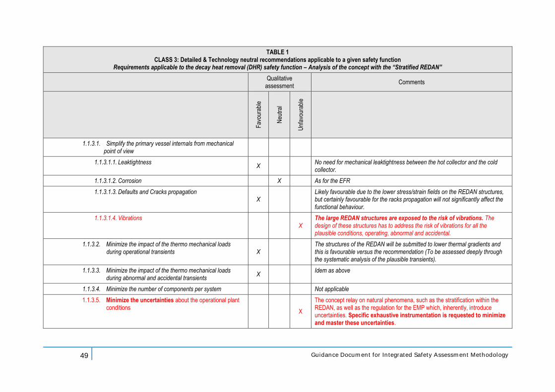
49 Guidance Document for Integrated Safety Assessment Methodology
TABLE 1 CLASS 3: Detailed & Technology neutral recommendations applicable to a given safety function
Requirements applicable to the decay heat removal (DHR) safety function – Analysis of the concept with the “Stratified REDAN”
Qualitative
assessment Comments
Fav
oura
ble
Neu
tral
Unf
avou
rabl
e
1.1.3.1. Simplify the primary vessel internals from mechanical point of view
1.1.3.1.1. Leaktightness X
No need for mechanical leaktightness between the hot collector and the cold collector.
1.1.3.1.2. Corrosion X As for the EFR
1.1.3.1.3. Defaults and Cracks propagation X
Likely favourable due to the lower stress/strain fields on the REDAN structures, but certainly favourable for the racks propagation will not significantly affect the functional behaviour.
1.1.3.1.4. Vibrations X
The large REDAN structures are exposed to the risk of vibrations. The design of these structures has to address the risk of vibrations for all the plausible conditions, operating, abnormal and accidental.
1.1.3.2. Minimize the impact of the thermo mechanical loads during operational transients X
The structures of the REDAN will be submitted to lower thermal gradients and this is favourable versus the recommendation (To be assessed deeply through the systematic analysis of the plausible transients).
1.1.3.3. Minimize the impact of the thermo mechanical loads during abnormal and accidental transients
X Idem as above
1.1.3.4. Minimize the number of components per system Not applicable
1.1.3.5. Minimize the uncertainties about the operational plant conditions
X
The concept relay on natural phenomena, such as the stratification within the REDAN, as well as the regulation for the EMP which, inherently, introduce uncertainties. Specific exhaustive instrumentation is requested to minimize and master these uncertainties.
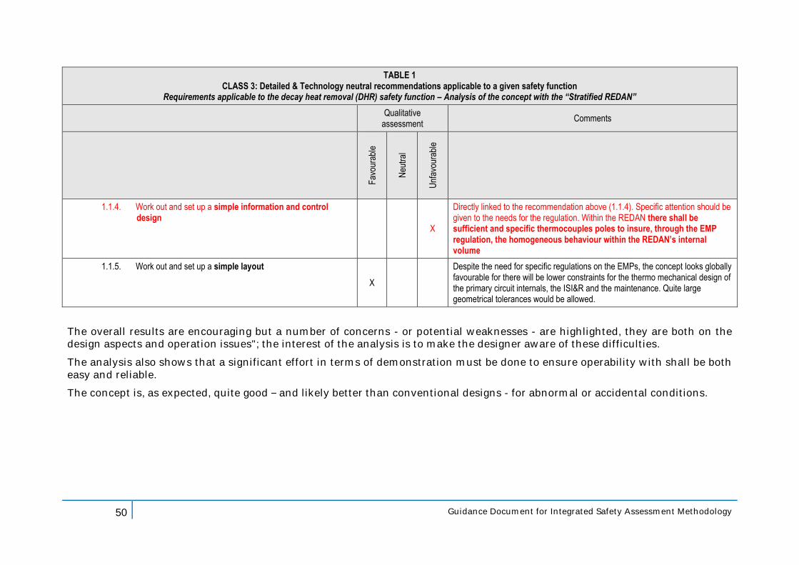
50 Guidance Document for Integrated Safety Assessment Methodology
TABLE 1 CLASS 3: Detailed & Technology neutral recommendations applicable to a given safety function
Requirements applicable to the decay heat removal (DHR) safety function – Analysis of the concept with the “Stratified REDAN”
Qualitative
assessment Comments
Fav
oura
ble
Neu
tral
Unf
avou
rabl
e
1.1.4. Work out and set up a simple information and control design
X
Directly linked to the recommendation above (1.1.4). Specific attention should be given to the needs for the regulation. Within the REDAN there shall be sufficient and specific thermocouples poles to insure, through the EMP regulation, the homogeneous behaviour within the REDAN’s internal volume
1.1.5. Work out and set up a simple layout
X
Despite the need for specific regulations on the EMPs, the concept looks globally favourable for there will be lower constraints for the thermo mechanical design of the primary circuit internals, the ISI&R and the maintenance. Quite large geometrical tolerances would be allowed.
The overall results are encouraging but a number of concerns - or potential weaknesses - are highlighted, they are both on the design aspects and operation issues"; the interest of the analysis is to make the designer aware of these difficulties.
The analysis also shows that a significant effort in terms of demonstration must be done to ensure operability with shall be both easy and reliable.
The concept is, as expected, quite good and likely better than conventional designs - for abnormal or accidental conditions.
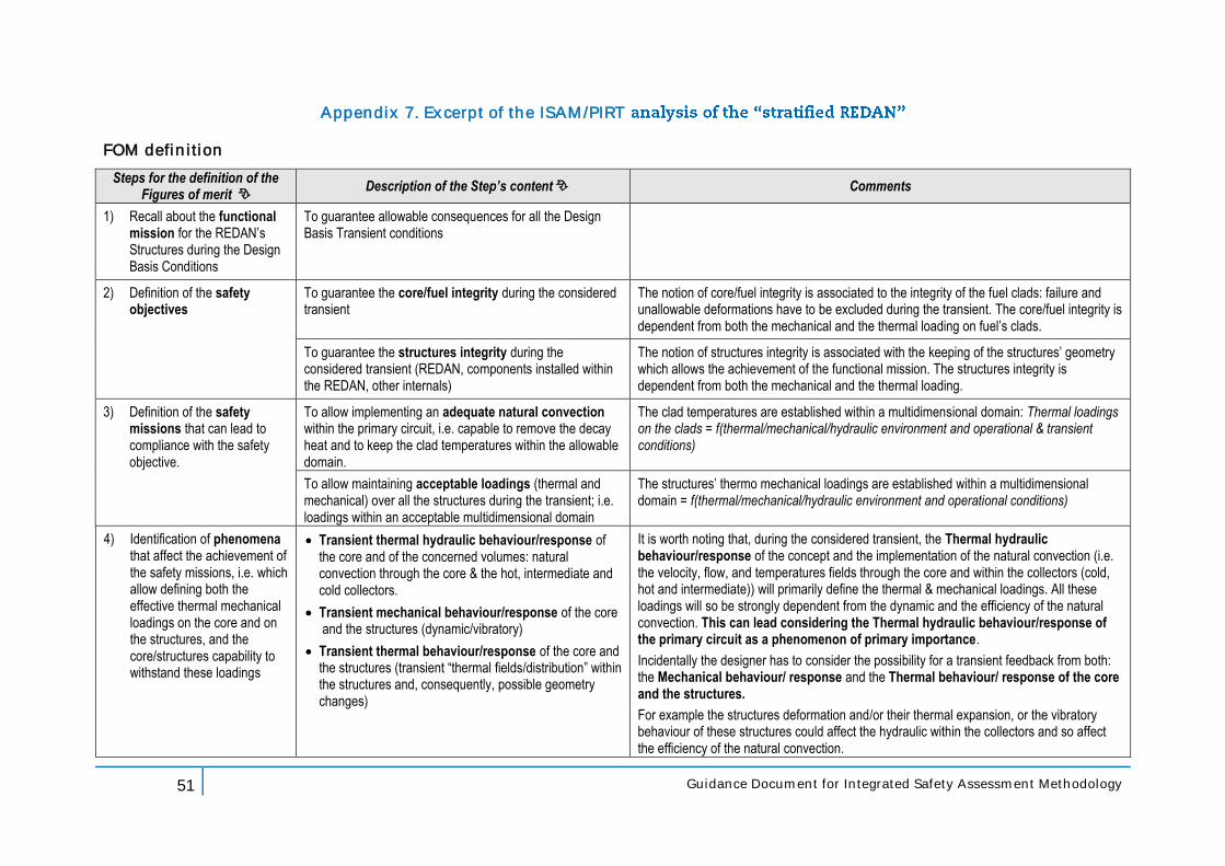
51 Guidance Document for Integrated Safety Assessment Methodology
Appendix 7. Excerpt of the ISAM/PIRT
FOM definition
Steps for the definition of the Figures of merit
Description of the Step’s content Comments
1) Recall about the functional mission for the REDAN’s Structures during the Design Basis Conditions
To guarantee allowable consequences for all the Design Basis Transient conditions
2) Definition of the safety objectives
To guarantee the core/fuel integrity during the considered transient
The notion of core/fuel integrity is associated to the integrity of the fuel clads: failure and unallowable deformations have to be excluded during the transient. The core/fuel integrity is dependent from both the mechanical and the thermal loading on fuel’s clads.
To guarantee the structures integrity during the considered transient (REDAN, components installed within the REDAN, other internals)
The notion of structures integrity is associated with the keeping of the structures’ geometry which allows the achievement of the functional mission. The structures integrity is dependent from both the mechanical and the thermal loading.
3) Definition of the safety missions that can lead to compliance with the safety objective.
To allow implementing an adequate natural convection within the primary circuit, i.e. capable to remove the decay heat and to keep the clad temperatures within the allowable domain.
The clad temperatures are established within a multidimensional domain: Thermal loadings on the clads = f(thermal/mechanical/hydraulic environment and operational & transient conditions)
To allow maintaining acceptable loadings (thermal and mechanical) over all the structures during the transient; i.e. loadings within an acceptable multidimensional domain
The structures’ thermo mechanical loadings are established within a multidimensional domain = f(thermal/mechanical/hydraulic environment and operational conditions)
4) Identification of phenomena that affect the achievement of the safety missions, i.e. which allow defining both the effective thermal mechanical loadings on the core and on the structures, and the core/structures capability to withstand these loadings
Transient thermal hydraulic behaviour/response of the core and of the concerned volumes: natural convection through the core & the hot, intermediate and cold collectors.
Transient mechanical behaviour/response of the core and the structures (dynamic/vibratory)
Transient thermal behaviour/response of the core and the structures (transient “thermal fields/distribution” within the structures and, consequently, possible geometry changes)
It is worth noting that, during the considered transient, the Thermal hydraulic behaviour/response of the concept and the implementation of the natural convection (i.e. the velocity, flow, and temperatures fields through the core and within the collectors (cold, hot and intermediate)) will primarily define the thermal & mechanical loadings. All these loadings will so be strongly dependent from the dynamic and the efficiency of the natural convection. This can lead considering the Thermal hydraulic behaviour/response of the primary circuit as a phenomenon of primary importance.
Incidentally the designer has to consider the possibility for a transient feedback from both: the Mechanical behaviour/ response and the Thermal behaviour/ response of the core and the structures.
For example the structures deformation and/or their thermal expansion, or the vibratory behaviour of these structures could affect the hydraulic within the collectors and so affect the efficiency of the natural convection.
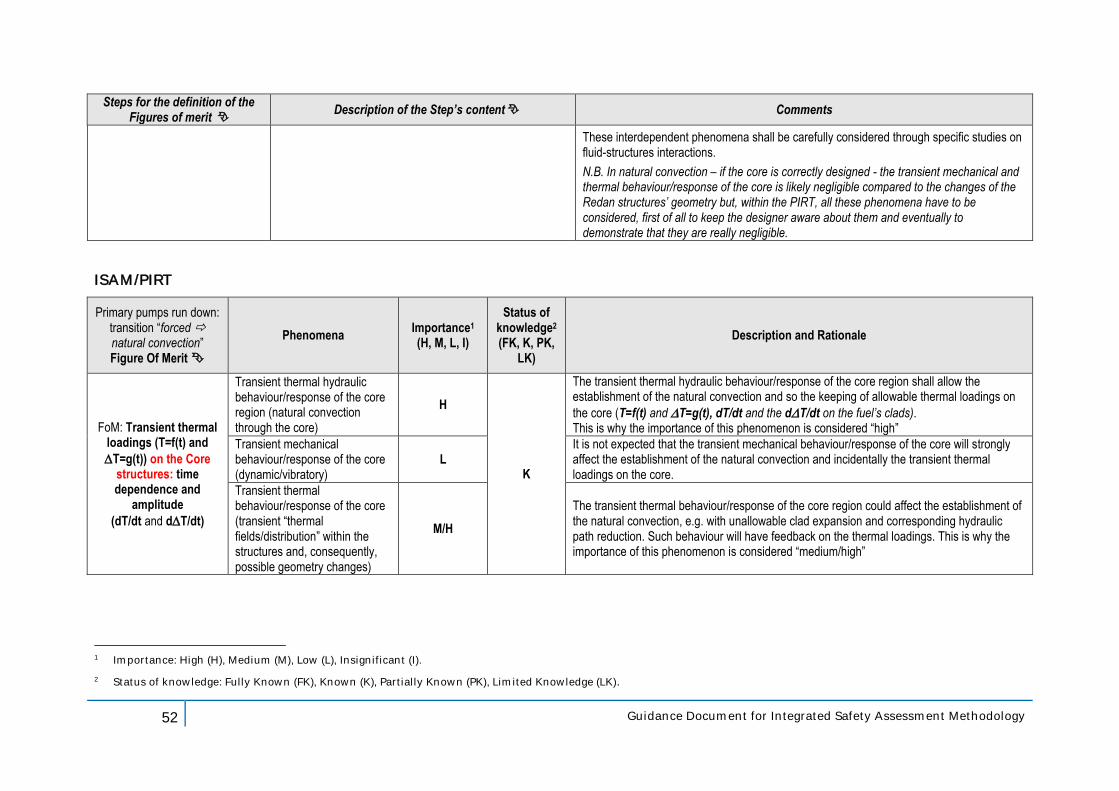
52 Guidance Document for Integrated Safety Assessment Methodology
Steps for the definition of the Figures of merit
Description of the Step’s content Comments
These interdependent phenomena shall be carefully considered through specific studies on fluid-structures interactions.
N.B. In natural convection – if the core is correctly designed - the transient mechanical and thermal behaviour/response of the core is likely negligible compared to the changes of the Redan structures’ geometry but, within the PIRT, all these phenomena have to be considered, first of all to keep the designer aware about them and eventually to demonstrate that they are really negligible.
ISAM/PIRT
Primary pumps run down: transition “forced natural convection” Figure Of Merit
Phenomena Importance1 (H, M, L, I)
Status of knowledge2 (FK, K, PK,
LK)
Description and Rationale
FoM: Transient thermal loadings (T=f(t) and
T=g(t)) on the Core structures: time dependence and
amplitude
(dT/dt and dT/dt)
Transient thermal hydraulic behaviour/response of the core region (natural convection through the core)
H
K
The transient thermal hydraulic behaviour/response of the core region shall allow the establishment of the natural convection and so the keeping of allowable thermal loadings on
the core (T=f(t) and T=g(t), dT/dt and the dT/dt on the fuel’s clads). This is why the importance of this phenomenon is considered “high”
Transient mechanical behaviour/response of the core (dynamic/vibratory)
L It is not expected that the transient mechanical behaviour/response of the core will strongly affect the establishment of the natural convection and incidentally the transient thermal loadings on the core.
Transient thermal behaviour/response of the core (transient “thermal fields/distribution” within the structures and, consequently, possible geometry changes)
M/H
The transient thermal behaviour/response of the core region could affect the establishment of the natural convection, e.g. with unallowable clad expansion and corresponding hydraulic path reduction. Such behaviour will have feedback on the thermal loadings. This is why the importance of this phenomenon is considered “medium/high”
1 Importance: High (H), Medium (M), Low (L), Insignificant (I).
2 Status of knowledge: Fully Known (FK), Known (K), Partially Known (PK), Limited Knowledge (LK).
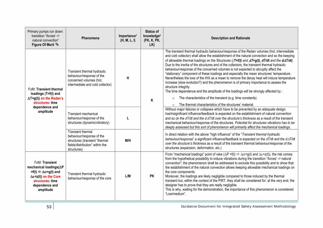
53 Guidance Document for Integrated Safety Assessment Methodology
Primary pumps run down: transition “forced natural convection” Figure Of Merit
Phenomena Importance1 (H, M, L, I)
Status of knowledge2 (FK, K, PK,
LK)
Description and Rationale
FoM: Transient thermal loadings (T=f(t) and
T=g(t)) on the Redan’s structures: time dependence and
amplitude
Transient thermal hydraulic behaviour/response of the concerned volumes (hot, intermediate and cold collector)
H
K
The transient thermal hydraulic behaviour/response of the Redan volumes (hot, intermediate and cold collector) shall allow the establishment of the natural convection and so the keeping
of allowable thermal loadings on the Structures ((T=f(t) and T=g(t), dT/dt and the dT/dt). Due to the inertia of the structures and of the collectors, the transient thermal hydraulic behaviour/response of the concerned volumes is not expected to abruptly affect the “stationary” component of these loadings and especially the mean structures’ temperature. Nevertheless the loss of the IHX as a mean to remove the decay heat will induce temperature increase (slow evolution?) and the phenomenon is of primary importance to assess the structure integrity. The time dependence and the amplitude of the loadings will be strongly affected by :
o The characteristics of the transient (e.g. time constants)
o The thermal characteristics of the structures’ material.
Transient mechanical behaviour/response of the structures (dynamic/vibratory)
L
Without major failures or collapses which have to be prevented by an adequate design, low/insignificant influence/feedback is expected on the establishment of natural convention
and so on the dT/dt and the dT/dt over the structure’s thickness as a result of the transient mechanical behaviour/response of the structures. Potential for structures vibrations has to be deeply assessed but this sort of phenomenon will primarily affect the mechanical loadings.
Transient thermal behaviour/response of the structures (transient “thermal fields/distribution” within the structures)
M/H
In direct relation with the above “high influence” of the “Transient thermal hydraulic
behaviour/response” a significant influence/feedback is expected on the dT/dt and the dT/dt over the structure’s thickness as a result of the transient thermal behaviour/response of the structures (expansion, deformation, etc.)
FoM: Transient
mechanical loadings(P
=f(t) =g(t) and
=z(t)) on the Core structures: time dependence and
amplitude
Transient thermal hydraulic behaviour/response of the core
L/M PK
From “mechanical loadings” point of view (P =f(t) =g(t) and =z(t)), the risk comes from the hypothetical possibility to induce vibrations during the transition “forced natural convection”; the phenomenon shall be addressed to exclude this possibility and to show that the establishment of the natural convection allows keeping allowable mechanical loadings on the core components. Moreover, the loadings are likely negligible compared to those induced by the thermal transient but, within the context of the PIRT, they shall be considered for, at the very end, the designer has to prove that they are really negligible. This is why, waiting for the demonstration, the importance of this phenomenon is considered “Low/medium”.
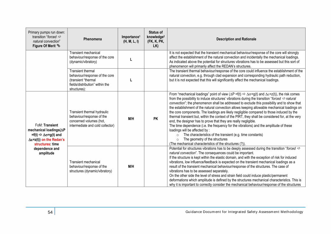
54 Guidance Document for Integrated Safety Assessment Methodology
Primary pumps run down: transition “forced natural convection” Figure Of Merit
Phenomena Importance1 (H, M, L, I)
Status of knowledge2 (FK, K, PK,
LK)
Description and Rationale
Transient mechanical behaviour/response of the core (dynamic/vibratory)
L
It is not expected that the transient mechanical behaviour/response of the core will strongly affect the establishment of the natural convection and incidentally the mechanical loadings. As indicated above the potential for structures vibrations has to be assessed but this sort of phenomenon will primarily affect the REDAN’s structures.
Transient thermal behaviour/response of the core (transient “thermal fields/distribution” within the structures):
L
The transient thermal behaviour/response of the core could influence the establishment of the natural convection, e.g. through clad expansion and corresponding hydraulic path reduction, but it is not expected that this will significantly affect the mechanical loadings.
FoM: Transient
mechanical loadings(P
=f(t) =g(t) and
=z(t)) on the Redan’s structures: time dependence and
amplitude
Transient thermal hydraulic behaviour/response of the concerned volumes (hot, intermediate and cold collector)
M/H PK
From “mechanical loadings” point of view (P =f(t) =g(t) and =z(t)), the risk comes from the possibility to induce structures’ vibrations during the transition “forced natural convection”; the phenomenon shall be addressed to exclude this possibility and to show that the establishment of the natural convection allows keeping allowable mechanical loadings on the core components. The loadings are likely negligible compared to those induced by the thermal transient but, within the context of the PIRT, they shall be considered for, at the very end, the designer has to prove that they are really negligible. The time dependence (i.e. the frequency for the vibrations) and the amplitude of these loadings will be affected by :
o The characteristics of the transient (e.g. time constants) o The geometry of the structures
(The mechanical characteristics of the structures (?)).
Transient mechanical behaviour/response of the structures (dynamic/vibratory)
M/H
Potential for structures vibrations has to be deeply assessed during the transition “forced natural convection”. The consequences could be important. If the structure is kept within the elastic domain, and with the exception of risk for induced vibrations, low influence/feedback is expected on the transient mechanical loadings as a result of the transient mechanical behaviour/response of the structures. The case of vibrations has to be assessed separately. On the other side the level of stress and strain field could induce plastic/permanent deformations which amplitude is defined by the structures mechanical characteristics. This is why it is important to correctly consider the mechanical behaviour/response of the structures
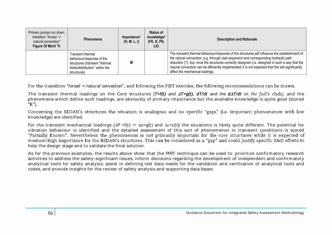
55 Guidance Document for Integrated Safety Assessment Methodology
Primary pumps run down: transition “forced natural convection” Figure Of Merit
Phenomena Importance1 (H, M, L, I)
Status of knowledge2 (FK, K, PK,
LK)
Description and Rationale
Transient thermal behaviour/response of the structures (transient “thermal fields/distribution” within the structures)
M
The transient thermal behaviour/response of the structures will influence the establishment of the natural convection, e.g. through clad expansion and corresponding hydraulic path reduction (?), but, once the structures correctly designed (i.e. designed in such a way that the natural convection can be efficiently implemented) it is not expected that this will significantly affect the mechanical loadings.
forced natural convection
The transient thermal loadings on the Core structures (T=f(t) and T=g(t), dT/dt and the dT/dt , and the phenomena which define such loadings, are obviously of primary importance but the available knowledge is quite good (scored
knowledge) are identified.
For the transient mechanical loadings (P =f(t) =g(t) and =z(t)) the situations is likely quite different. The potential for vibration behaviour is identified and the detailed assessment of this sort of phenomenon in transient conditions is scored
medium/help the design stage and to validate the final solution.
As for the previous examples, the results above show that the PIRT technique can be used to: prioritize confirmatory research activities to address the safety-significant issues; inform decisions regarding the development of independent and confirmatory analytical tools for safety analysis; assist in defining test data needs for the validation and verification of analytical tools and codes, and provide insights for the review of safety analysis and supporting data bases.
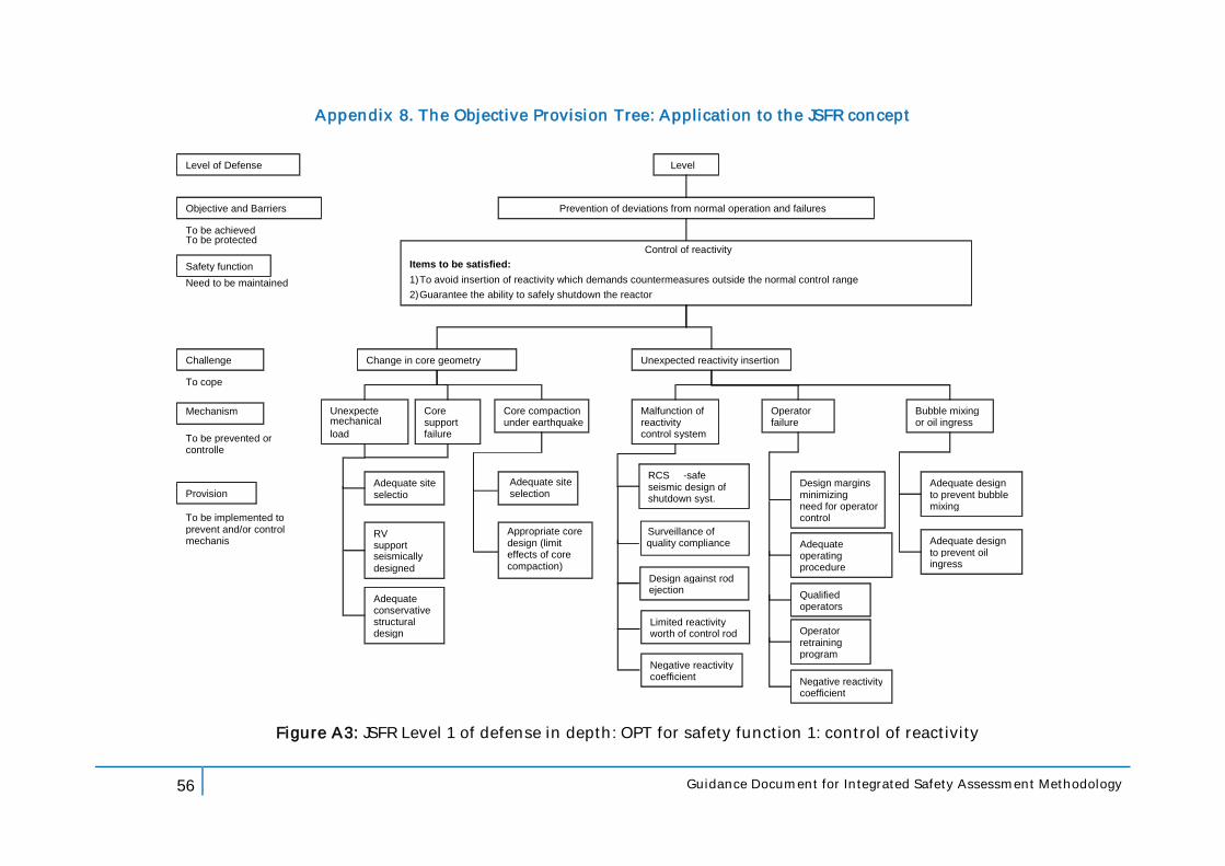
56 Guidance Document for Integrated Safety Assessment Methodology
Appendix 8. The Objective Provision Tree: Application to the JSFR concept
Level of Defense
Objective and Barriers
Safety function
Challenge
Mechanism
Provisions
To be achieved To be protected
Need to be maintained
To cope with
To be prevented or controlled
To be implemented to prevent and/or control mechanism
Level 1
Prevention of deviations from normal operation and failures
Control of reactivity Items to be satisfied: 1) To avoid insertion of reactivity which demands countermeasures outside the normal control range 2) Guarantee the ability to safely shutdown the reactor
Change in core geometry Unexpected reactivity insertion
Unexpected mechanical loads
Core support failure
Core compaction under earthquake
Malfunction of reactivity control system
Operator failure
Adequate site selection
RV and supports seismically designed
Adequate and conservative structural design
Appropriate core design (limit effects of core compaction)
RCS fail
- safe and seismic design of
shutdown syst.
Surveillance of quality compliance
Design against rod ejection
Limited reactivity worth of control rod
Negative reactivity coefficient
Design margins minimizing the need for operator control
Adequate operating procedure
Qualified operators
Operator retraining program
Negative reactivity coefficient
Figure A3: JSFR Level 1 of defense in depth: OPT for safety function 1: control of reactivity
Bubble mixing or oil ingress
Adequate design to prevent bubble mixing
Adequate design to prevent oil ingress
Adequate site selection
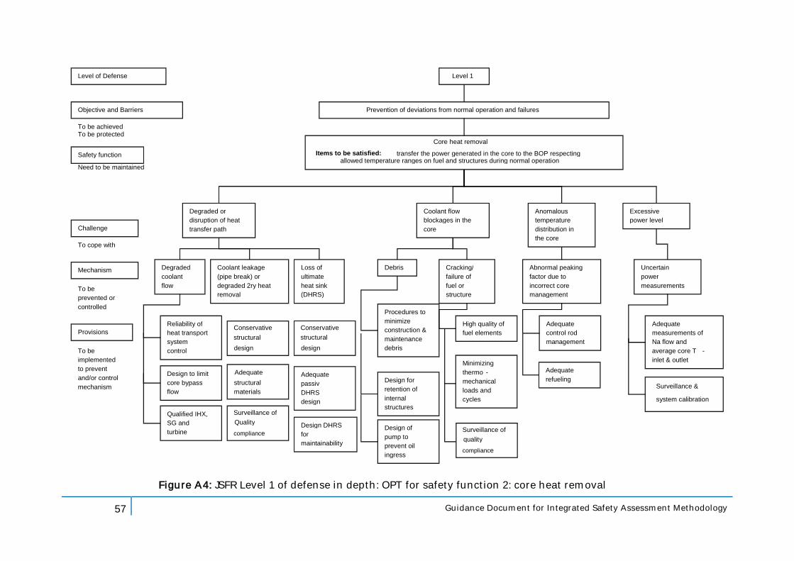
57 Guidance Document for Integrated Safety Assessment Methodology
Level of Defense
Objective and Barriers
Safety function
Challenge
Mechanism
Provisions
To be achieved To be protected
Need to be maintained
To cope with
To be prevented or controlled
To be implemented to prevent and/or control mechanism
Level 1
Prevention of deviations from normal operation and failures
Core heat removal Items to be satisfied: transfer the power generated in the core to the BOP respecting
allowed temperature ranges on fuel and structures during normal operation
Degraded or disruption of heat transfer path
Coolant flow blockages in the core
Degraded coolant flow
Coolant leakage (pipe break) or degraded 2ry heat removal
Loss of ultimate heat sink (DHRS)
Debris Abnormal peaking factor due to incorrect core management
Reliability of heat transport system control
Design to limit core bypass flow
Qualified IHX, SG and turbine
Adequate passive DHRS T/H design
Procedures to minimize construction & maintenance debris
Design for retention of internal structures
Design of pump to prevent oil ingress
Adequate control rod management
Figure A4: JSFR Level 1 of defense in depth: OPT for safety function 2: core heat removal
Uncertain power measurements
Adequate measurements of Na flow and average core T - inlet & outlet
Surveillance &
system calibration
Anomalous temperature distribution in the core
Excessive power level
Cracking/ failure of fuel or structure
Design DHRS for maintainability
High quality of fuel elements
Minimizing thermo - mechanical loads and cycles
Adequate refueling
Conservative structural design
Adequate structural materials
Surveillance of Quality compliance
Conservative structural design
Surveillance of quality compliance
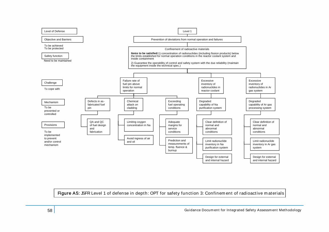
58 Guidance Document for Integrated Safety Assessment Methodology
Level of Defense
Objective and Barriers
Safety function
Challenge
Mechanism
Provisions
To be achieved To be protected
Need to be maintained
To cope with
To be prevented or controlled
To be implemented to prevent and/or control mechanism
Level 1
Prevention of deviations from normal operation and failures
Confinement of radioactive materials Items to be satisfied: 1) concentration of radionuclides (including fission products) below the limits established for normal operation conditions in the reactor coolant system and inside containment 2) Guarantee the operability of control and safety system with the due reliability (maintain the equipment inside the technical spec.)
Failure rate of fuel pin above limits for normal operation
Defects in as - fabricated fuel pin
Exceeding fuel operating conditions
Degraded capability of Na purification system
QA and QC of fuel design and fabrication
Adequate margins for service conditions
Prediction and measurements of temp. fluence & burnup
Clear definition of normal and abnormal conditions
Figure A5: JSFR Level 1 of defense in depth: OPT for safety function 3: Confinement of radioactive materials
Excessive inventory of radionuclides in reactor coolant
Chemical attack on cladding
Limiting oxygen concentration in Na
Avoid ingress of air and oil Limit radionuclide
inventory in Na purification system
Design for external and internal hazard
Degraded capability of Ar gas processing system
Clear definition of normal and abnormal conditions
Excessive inventory of radionuclides in Ar gas system
Limit radionuclide inventory in Ar gas system
Design for external and internal hazard
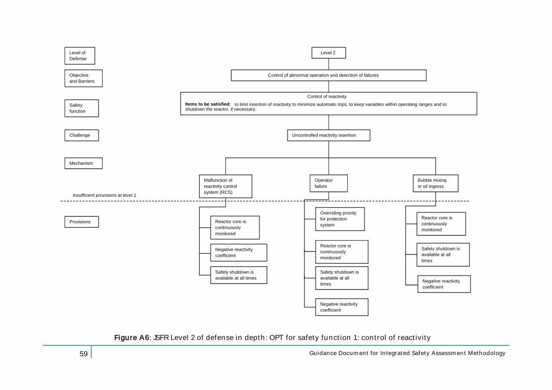
59 Guidance Document for Integrated Safety Assessment Methodology
Level of Defense
Objective and Barriers
Safety function
Challenge
Mechanism
Provisions
Level 2
Control of abnormal operation and detection of failures
Control of reactivity Items to be satisfied: to limit insertion of reactivity to minimize automatic trips, to keep variables within operating ranges and to shutdown the reactor, if necessary.
Uncontrolled reactivity insertion
Malfunction of reactivity control system (RCS)
Operator failure
Reactor core is continuously monitored
Negative reactivity coefficient
Safety shutdown is available at all times
Overriding priority for protection system
Reactor core is continuously monitored
Safety shutdown is available at all times
Negative reactivity coefficient
Figure A6: JSFR Level 2 of defense in depth: OPT for safety function 1: control of reactivity
Bubble mixing or oil ingress
Reactor core is continuously monitored
Insufficient provisions at level 1
Safety shutdown is available at all times
Negative reactivity coefficient
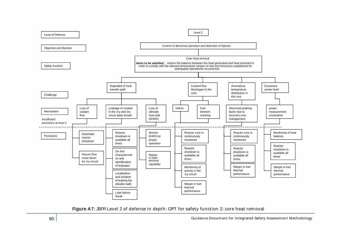
60 Guidance Document for Integrated Safety Assessment Methodology
Level of Defense
Objective and Barriers
Safety function
Challenge
Mechanism
Provisions
Level 2
Control of abnormal operation and detection of failures
Core heat removal Items to be satisfied: restore the balance between the heat generated and heat removed in
order to comply with the allowed temperature ranges on fuel and structures established for anticipated operational occurrences
Degraded of heat transfer path
Coolant flow blockages in the core
Loss of coolant flow
Leakage of coolant in the 1ry and 2ry circuit (pipe break)
Loss of ultimate heat sink (DHRS)
Debris Abnormal peaking factor due to incorrect core management
Automatic reactor shutdown
Secure flow coast down for 1ry circuit
Monitor DHRS for proper operation
Reactor core is continuously monitored
Reactor shutdown is available all times
Monitoring of activity in the 1ry circuit
Figure A7: JSFR Level 2 of defense in depth: OPT for safety function 2: core heat removal
power measurement uncertainty
Monitoring of heat balance
Anomalous temperature distribution in the core
Excessive power level
Fuel element cracking
Reactor shutdown is available all times
On - line characterizati on and identification of leakages
Localization and isolation of leaking Na (double wall)
Insufficient provisions at level 1
Leak before break
Margin in fuel thermal performance
Reactor core is continuously monitored
Reactor shutdown is available all times
Margin in fuel thermal performance
Margin in heat removal capability
Reactor shutdown is available all times
Margin in fuel thermal performance
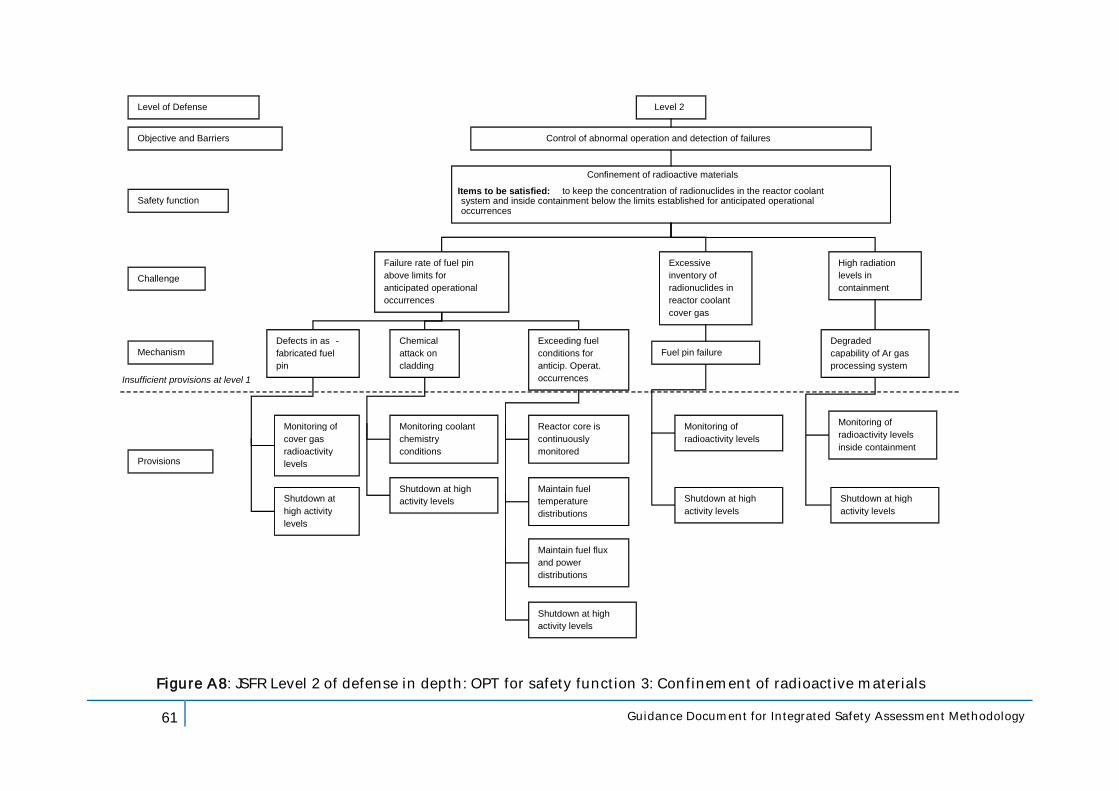
61 Guidance Document for Integrated Safety Assessment Methodology
Level of Defense
Objective and Barriers
Safety function
Challenge
Mechanism
Provisions
Level 2
Control of abnormal operation and detection of failures
Confinement of radioactive materials Items to be satisfied: to keep the concentration of radionuclides in the reactor coolant system and inside containment below the limits established for anticipated operational occurrences
Failure rate of fuel pin above limits for anticipated operational occurrences
Defects in as - fabricated fuel pin
Exceeding fuel conditions for anticip. Operat. occurrences
Fuel pin failure
Monitoring of cover gas radioactivity levels
Reactor core is continuously monitored
Maintain fuel temperature distributions
Monitoring of radioactivity levels
Figure A8: JSFR Level 2 of defense in depth: OPT for safety function 3: Confinement of radioactive materials
Excessive inventory of radionuclides in reactor coolant cover gas
Chemical attack on cladding
Monitoring coolant chemistry conditions
Shutdown at high activity levels Shutdown at high
activity levels
Insufficient provisions at level 1
Shutdown at high activity levels
Maintain fuel flux and power distributions
Shutdown at high activity levels
High radiation levels in containment
Degraded capability of Ar gas processing system
Monitoring of radioactivity levels inside containment
Shutdown at high activity levels
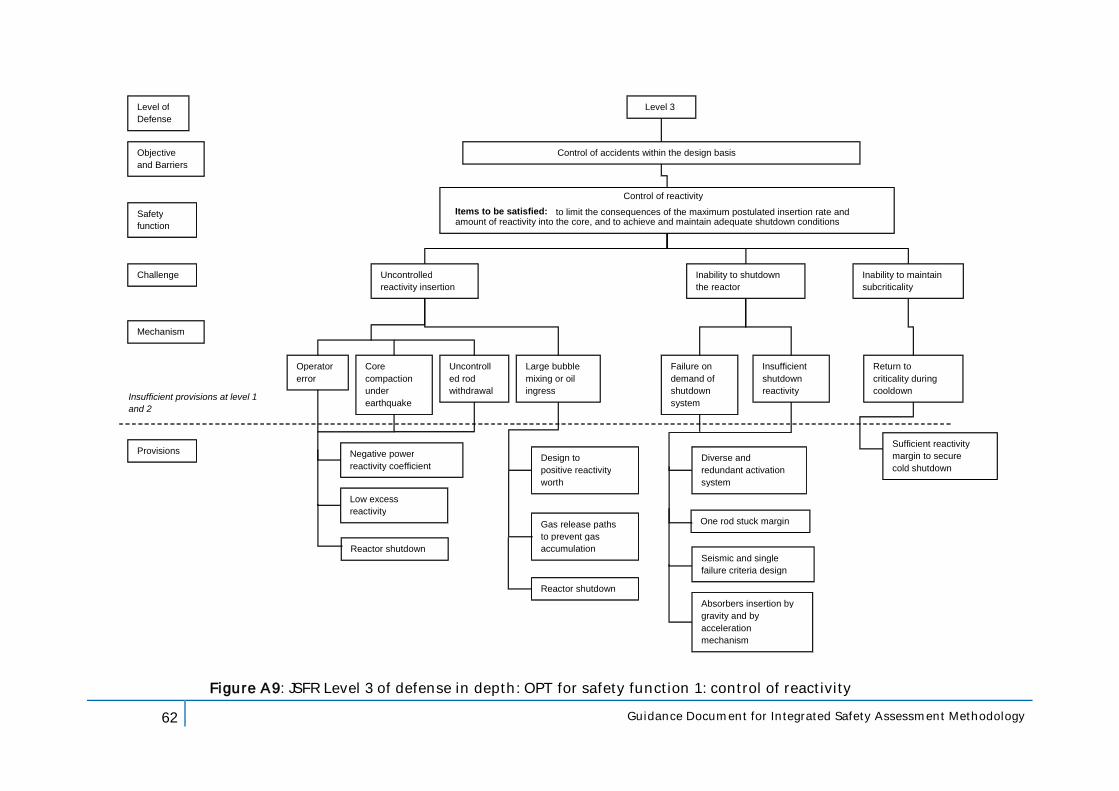
62 Guidance Document for Integrated Safety Assessment Methodology
Level of Defense
Objective and Barriers
Safety function
Challenge
Mechanism
Provisions
Level 3
Control of accidents within the design basis
Control of reactivity Items to be satisfied: to limit the consequences of the maximum postulated insertion rate and amount of reactivity into the core, and to achieve and maintain adequate shutdown conditions
Uncontrolled reactivity insertion
Uncontroll ed rod withdrawal
Insufficient shutdown reactivity
Diverse and redundant activation system
Seismic and single failure criteria design
Absorbers insertion by gravity and by acceleration mechanism
Figure A9: JSFR Level 3 of defense in depth: OPT for safety function 1: control of reactivity
Return to criticality during cooldown
Sufficient reactivity margin to secure cold shutdown
Insufficient provisions at level 1 and 2
Operator error
Core compaction under earthquake
Negative power reactivity coefficient
One rod stuck margin
Low excess reactivity
Inability to shutdown the reactor
Failure on demand of shutdown system
Inability to maintain subcriticality
Large bubble mixing or oil ingress
Design to limit positive reactivity worth
Gas release paths to prevent gas accumulation
Reactor shutdown
Reactor shutdown
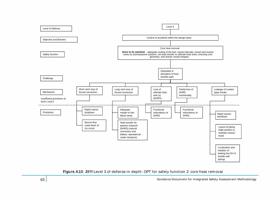
63 Guidance Document for Integrated Safety Assessment Methodology
Level of Defense
Objective and Barriers
Safety function
Challenge
Mechanism
Provisions
Level 3
Control of accidents within the design basis
Core heat removal Items to be satisfied: adequate cooling of the fuel, vessel internals, vessel and reactor cavity by active/passive systems, via heat transfer to ultimate heat sinks, ensuring core
geometry, and reactor vessel integrity
Degraded or disruption of heat transfer path
Long - term loss of forced convection
Loss of ultimate heat sink (s) (DHRS)
Partial loss of DHRS functionality
Leakage of coolant (pipe break)
Functional redundancy of DHRS
Functional redundancy of DHRS
Figure A10: JSFR Level 3 of defense in depth: OPT for safety function 2: core heat removal
Adequate margin to fuel failure temp.
Heat transfer by passive measure (DHRS) (natural convection and battery - operated air - cooler dumpers)
Insufficient provisions at level 1 and 2
Layout of piping (high position to maintain reactor level)
Localization and isolation of leaking Na (GV & double wall piping)
Short - term loss of forced convection
Rapid reactor shutdown
Secure flow coast down of 1ry circuit
Rapid reactor shutdown
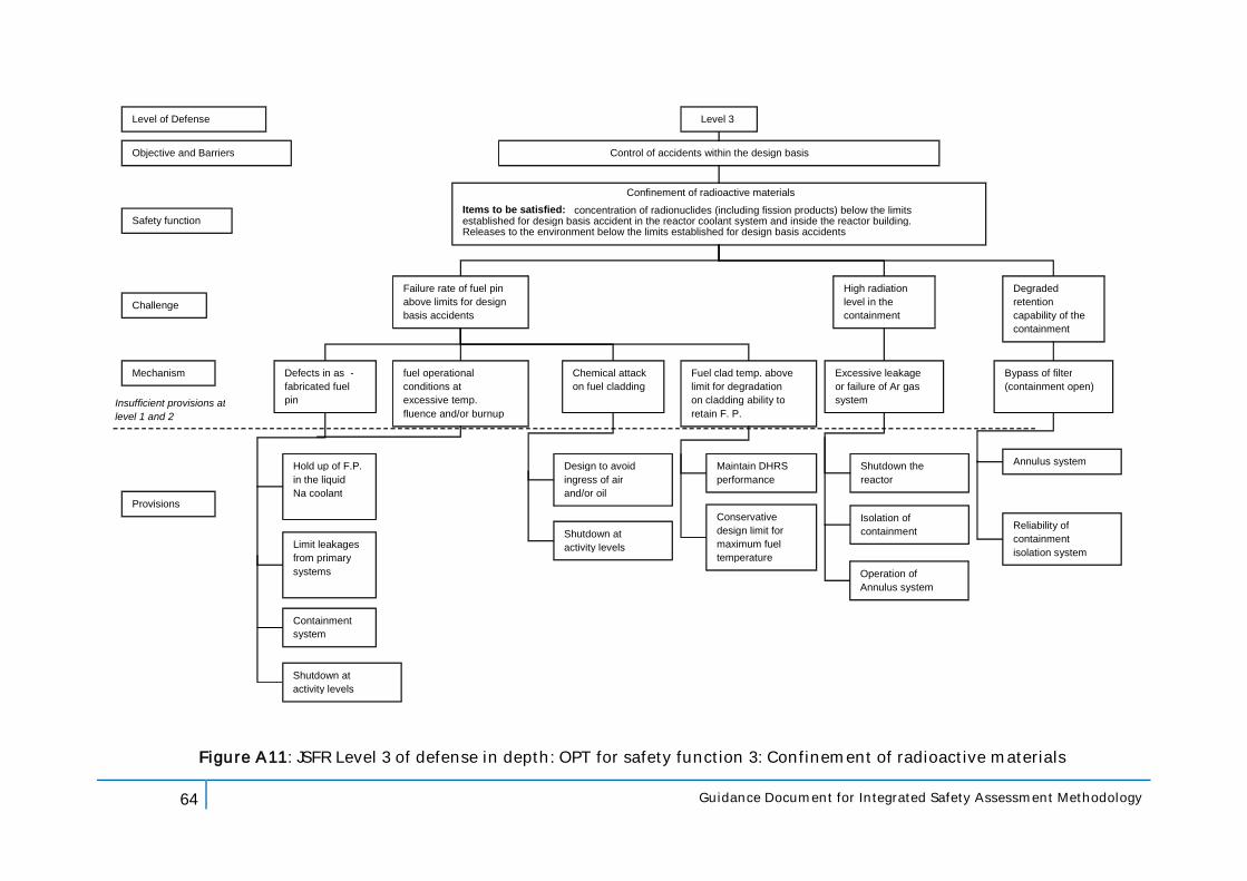
64 Guidance Document for Integrated Safety Assessment Methodology
Level of Defense
Objective and Barriers
Safety function
Challenge
Mechanism
Provisions
Level 3
Control of accidents within the design basis
Confinement of radioactive materials Items to be satisfied: concentration of radionuclides (including fission products) below the limits established for design basis accident in the reactor coolant system and inside the reactor building. Releases to the environment below the limits established for design basis accidents
Failure rate of fuel pin above limits for design basis accidents
Defects in as - fabricated fuel pin
Fuel clad temp. above limit for degradation on cladding ability to retain F. P.
Excessive leakage or failure of Ar gas system
Hold up of F.P. in the liquid Na coolant
Maintain DHRS performance
Conservative design limit for maximum fuel temperature
Shutdown the reactor
Figure A11: JSFR Level 3 of defense in depth: OPT for safety function 3: Confinement of radioactive materials
High radiation level in the containment
fuel operational conditions at excessive temp. fluence and/or burnup
Isolation of containment
Insufficient provisions at level 1 and 2
Limit leakages from primary systems
Degraded retention capability of the containment
Bypass of filter (containment open)
Annulus system
Containment system
Chemical attack on fuel cladding
Design to avoid ingress of air and/or oil
Shutdown at high activity levels
Reliability of containment isolation system
Operation of Annulus system
Shutdown at high activity levels
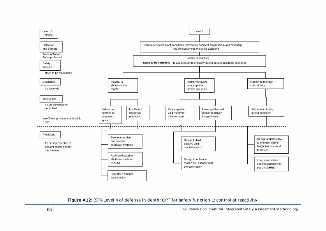
65 Guidance Document for Integrated Safety Assessment Methodology
Level of Defense
Objective and Barriers
Safety function
Challenge
Mechanism
Provisions
Level 4
Control of severe plant conditions, preventing accident progression, and mitigating the consequences of severe accidents
Control of reactivity Items to be satisfied: to avoid return to criticality during severe accidents scenarios
Insufficient shutdown reactivity
Additional passive shutdown system (SASS)
Figure A12: JSFR Level 4 of defense in depth: OPT for safety function 1: control of reactivity
Return to criticality during cooldown
Design of debris tray to maintain debris height below critical thickness
Insufficient provisions at level 1, 2 and 3
Inability to shutdown the reactor
Failure on demand of shutdown system
Inability to maintain subcriticality
Operator’s manual scram action
Unacceptable fuel motion reactivity insertion rate
Design to limit positive void reactivity worth
Inability to avoid unacceptable power excursion
Unacceptable void reactivity insertion rate
Design to enhance molten fuel escape from the core region
To be achieved To be protected
Need to be maintained
To cope with
To be prevented or controlled
To be implemented to prevent and/or control mechanism
Long - term debris cooling capability by passive DHRS
Two independent and diverse shutdown systems
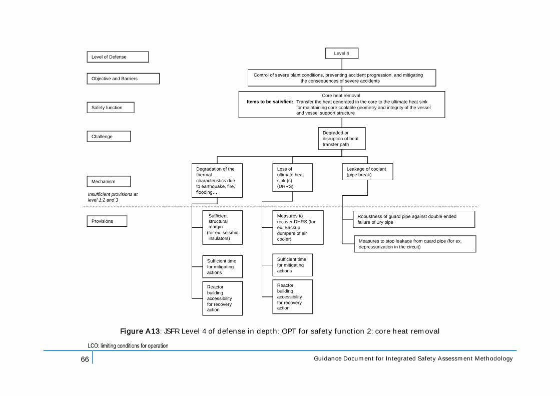
66 Guidance Document for Integrated Safety Assessment Methodology
Level of Defense
Objective and Barriers
Safety function
Challenge
Mechanism
Provisions
Level 4
Control of severe plant conditions, preventing accident progression, and mitigating the consequences of severe accidents
Core heat removal Items to be satisfied: Transfer the heat generated in the core to the ultimate heat sink
for maintaining core coolable geometry and integrity of the vessel and vessel support structure
Degraded or disruption of heat transfer path
Degradation of the thermal characteristics due to earthquake, fire, flooding…
Loss of ultimate heat sink (s) (DHRS)
Leakage of coolant (pipe break)
Measures to recover DHRS (for ex. Backup dumpers of air cooler)
Figure A13: JSFR Level 4 of defense in depth: OPT for safety function 2: core heat removal
Sufficient structural margin
(for ex. seismic insulators)
Insufficient provisions at level 1,2 and 3
LCO: limiting conditions for operation
Robustness of guard pipe against double ended failure of 1ry pipe
Reactor building accessibility for recovery action
Sufficient time for mitigating actions
Reactor building accessibility for recovery action
Sufficient time for mitigating actions
Measures to stop leakage from guard pipe (for ex. depressurization in the circuit)
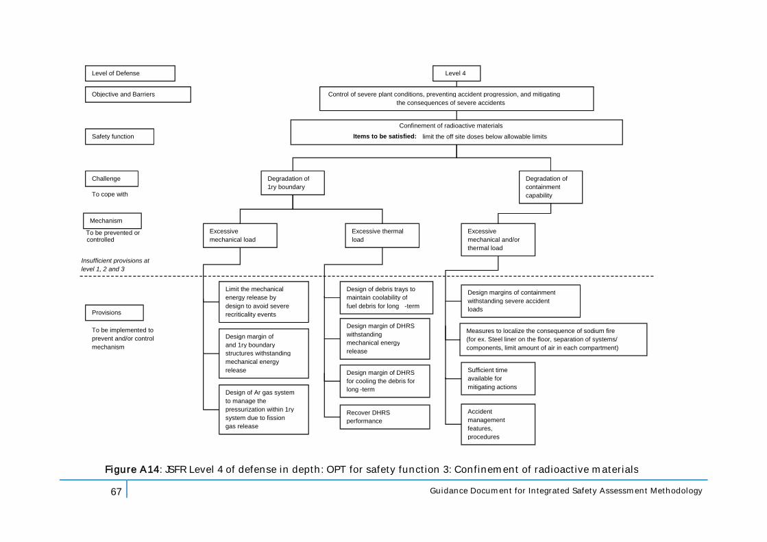
67 Guidance Document for Integrated Safety Assessment Methodology
Level of Defense
Objective and Barriers
Safety function
Challenge
Mechanism
Provisions
Level 4
Control of severe plant conditions, preventing accident progression, and mitigating the consequences of severe accidents
Confinement of radioactive materials Items to be satisfied: limit the off site doses below allowable limits
Excessive mechanical load
Limit the mechanical energy release by design to avoid severe recriticality events
Figure A14: JSFR Level 4 of defense in depth: OPT for safety function 3: Confinement of radioactive materials
Degradation of 1ry boundary
Design margin of RV and 1ry boundary structures withstanding mechanical energy release
Insufficient provisions at level 1, 2 and 3
Degradation of containment capability
Excessive mechanical and/or thermal load
Design margins of containment withstanding severe accident loads
To be prevented or controlled
To cope with
To be implemented to prevent and/or control mechanism
Excessive thermal load
Design of Ar gas system to manage the pressurization within 1ry system due to fission gas release
Design of debris trays to maintain coolability of fuel debris for long - term
Design margin of DHRS for cooling the debris for long - term
Recover DHRS performance
Design margin of DHRS withstanding mechanical energy release
Sufficient time available for mitigating actions
Accident management features, procedures
Measures to localize the consequence of sodium fire (for ex. Steel liner on the floor, separation of systems/ components, limit amount of air in each compartment)