Embed Size (px)
Citation preview

www.unipowerco.comNORTH AMERICA CALL: +1-954-346-2442 • EUROPE CALL: +44 (0)1903 768200
KEY FEATURES
>92.5% Efficiency Rectifiers
100A / 2.7kW Load Capacity
Remote Monitoring & Control
Field Replaceable Controller
Ethernet Comm. with SNMPv3
3 LED Alarm/Status Indicators
Up to 10 Form-C Relay Alarms
Up to 6 Load Breakers
2 Battery Breakers
LCD Display/Touchpad
Easy Installation
GUARDIAN ACCESS 2U24MODEL GDN.S.24.M28
2U Integrated DC Power System+24VDC | 100A | 2.7kW
DESCRIPTION
Guardian Access 2U24 is a 2RU high 19” rack-mounted, integrated DC power system providing an output of +24VDC. These systems can accomodate up to 3 Guardian FMP20.24G high efficiency hot-swap rectifiers. A total load current of 100A / 2.7kW is available with battery charge current up to 65A in addition. The rectifiers are internally fan cooled with speed control which is a function of load and temperature, keeping acoustic noise to a minimum.
The DC output circuits can provide up to 6 loads which utilize circuit breakers rated from 4A to 150A. 2 additional 80A, 100A or 125A breakers provide battery protection. A programmable 125A low voltage battery disconnect (LVD) is standard while a partial load disconnect (PLD), also rated at 125A and programmable, can provide non-critical load shedding when operating on batteries.
The ACC Extended remote access controller monitors system parameters, controls rectifier output, and provides alarms for system failures. The Controller Module is also pluggable for easy field replacement in case of failure. There are 2 LED alarm indicators which indicate failures, (RED) Alarm and (YELLOW) Message. A third green LED indicates the controller is working properly. As standard four form-C relay outputs provide the alarms for remote use. An additional 6 can be included as an option. Two digital inputs and outputs are also provided as well as a microSD card slot that accepts an up to 4GB card which is sufficient for more than 20 years data logging.
The system can be programmed by means of a remote PC web page display. Communication is by Ethernet LAN with SNMPv3 including alarm trapping. It also has provision for temperature compensated charging of an external battery using a supplied TC probe. An LCD Display/Touchpad is included for local metering, status, and setup.
The Guardian Access 2U is compatible with UNIPOWER’s free PowCom™ software which offers local and remote management through an advanced Windows GUI.
SAFETY COMPLIANCE
UL60950-1 2nd Ed.CSA22.2 No. 60950-1 2nd Ed.EN60950-1 2nd Ed.
TWO-YEAR WARRANTY
18 36 54 72 90 108 126 144 165
EFFICIENCY (230VAC)
Rectifier Current [load + charge]
Effi
cie
ncy
[%]
Max
. Lo
ad C
urr
ent
30% 70%
55
60
65
70
75
80
85
90
95
LVD2006/95/ECEMC2004/108/ECROHS2011/65/EU
UNIPOWER NORTH AMERICA • 3900 Coral Ridge Drive, Coral Springs, Florida 33065, USA • Tel: +1-954-346-2442 • Fax: +1-954-340-7901 • [email protected] EUROPE • Parkland Business Centre, Chartwell Road, Lancing, BN15 8UE, ENGLAND • Tel: +44(0)1903 768200 • [email protected]
Guardian Access 2U24 (GDN.S.24.M28) - 2
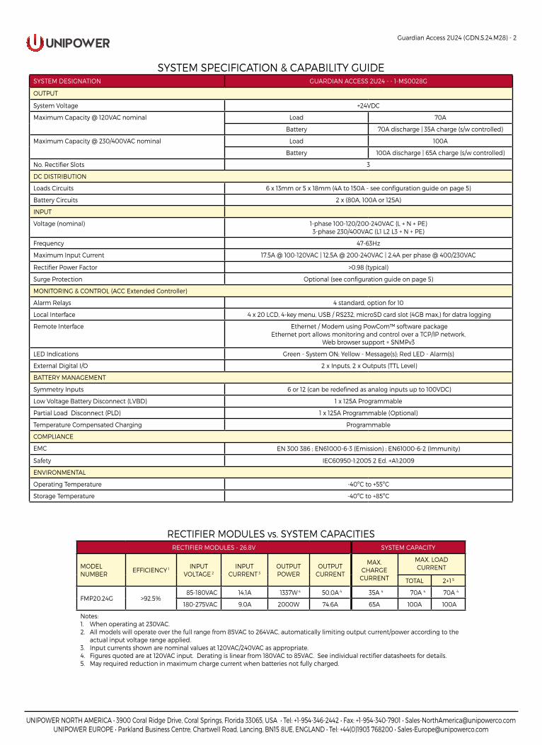
RECTIFIER MODULES vs. SYSTEM CAPACITIESRECTIFIER MODULES - 26.8V SYSTEM CAPACITY
MODELNUMBER
EFFICIENCY 1 INPUT VOLTAGE 2
INPUT CURRENT 3
OUTPUT POWER
OUTPUT CURRENT
MAX.CHARGE
CURRENT
MAX. LOADCURRENT
TOTAL 2+1 5
FMP20.24G >92.5%85-180VAC 14.1A 1337W 4 50.0A 4 35A 4 70A 4 70A 4
65A 100A 100A180-275VAC 9.0A 2000W 74.6A
Notes:1. When operating at 230VAC.2. All models will operate over the full range from 85VAC to 264VAC, automatically limiting output current/power according to the
actual input voltage range applied.3. Input currents shown are nominal values at 120VAC/240VAC as appropriate.4. Figures quoted are at 120VAC input. Derating is linear from 180VAC to 85VAC. See individual rectifier datasheets for details.5. May required reduction in maximum charge current when batteries not fully charged.
SYSTEM SPECIFICATION & CAPABILITY GUIDESYSTEM DESIGNATION GUARDIAN ACCESS 2U24 - - 1-MS0028G
OUTPUT
System Voltage +24VDC
Maximum Capacity @ 120VAC nominal Load 70A
Battery 70A discharge | 35A charge (s/w controlled)
Maximum Capacity @ 230/400VAC nominal Load 100A
Battery 100A discharge | 65A charge (s/w controlled)
No. Rectifier Slots 3
DC DISTRIBUTION
Loads Circuits 6 x 13mm or 5 x 18mm (4A to 150A - see configuration guide on page 5)
Battery Circuits 2 x (80A, 100A or 125A)
INPUT
Voltage (nominal) 1-phase 100-120/200-240VAC (L + N + PE)3-phase 230/400VAC (L1 L2 L3 + N + PE)
Frequency 47-63Hz
Maximum Input Current 17.5A @ 100-120VAC | 12.5A @ 200-240VAC | 2.4A per phase @ 400/230VAC
Rectifier Power Factor >0.98 (typical)
Surge Protection Optional (see configuration guide on page 5)
MONITORING & CONTROL (ACC Extended Controller)
Alarm Relays 4 standard, option for 10
Local Interface 4 x 20 LCD, 4-key menu, USB / RS232, microSD card slot (4GB max,) for datra logging
Remote Interface Ethernet / Modem using PowCom™ software packageEthernet port allows monitoring and control over a TCP/IP network.
Web browser support + SNMPv3
LED Indications Green - System ON; Yellow - Message(s); Red LED - Alarm(s)
External Digital I/O 2 x Inputs, 2 x Outputs (TTL Level)
BATTERY MANAGEMENT
Symmetry Inputs 6 or 12 (can be redefined as analog inputs up to 100VDC)
Low Voltage Battery Disconnect (LVBD) 1 x 125A Programmable
Partial Load Disconnect (PLD) 1 x 125A Programmable (Optional)
Temperature Compensated Charging Programmable
COMPLIANCE
EMC EN 300 386 ; EN61000-6-3 (Emission) ; EN61000-6-2 (Immunity)
Safety IEC60950-1:2005 2 Ed. +A1:2009
ENVIRONMENTAL
Operating Temperature -40ºC to +55ºC
Storage Temperature -40ºC to +85ºC
UNIPOWER NORTH AMERICA • 3900 Coral Ridge Drive, Coral Springs, Florida 33065, USA • Tel: +1-954-346-2442 • Fax: +1-954-340-7901 • [email protected] EUROPE • Parkland Business Centre, Chartwell Road, Lancing, BN15 8UE, ENGLAND • Tel: +44(0)1903 768200 • [email protected]
Guardian Access 2U24 (GDN.S.24.M28) - 3
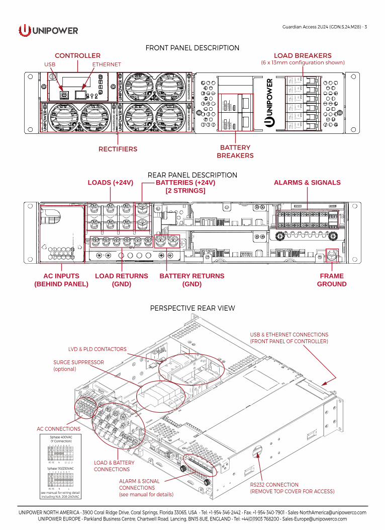
PERSPECTIVE REAR VIEW
FRONT PANEL DESCRIPTION
CB1
CB1
CB1
CB1
CB1
CB1
16ATR
IP
CU
RVE U
2
QY-1(13)-D
80V 10 KA 10
16ATR
IP
CU
RVE U
2
QY-1(13)-D
80V 10 KA 10
16ATR
IP
CU
RVE U
2
QY-1(13)-D
80V 10 KA 10
16ATR
IP
CU
RVE U
2
QY-1(13)-D
80V 10 KA 10
16ATR
IP
CU
RVE U
2
QY-1(13)-D
80V 10 KA 10
16ATR
IP
CU
RVE U
2
QY-1(13)-D
80V 10 KA 10
MER
LIN
GER
IN
mul
ti9C
120N
D10
0A41
5V~
1000
0
MER
LIN
GER
IN
mul
ti9C
120N
D10
0A41
5V~
1000
0
GU
AR
DIA
N 4
8
GU
AR
DIA
N 4
8G
UA
RD
IAN
48
RECTIFIERS BATTERYBREAKERS
CONTROLLER LOAD BREAKERS(6 x 13mm configuration shown)USB ETHERNET
LOAD RETURNS(GND)
BATTERY RETURNS(GND)
LOADS (+24V) ALARMS & SIGNALSBATTERIES (+24V)[2 STRINGS]
AC INPUTS(BEHIND PANEL)
FRAMEGROUND
REAR PANEL DESCRIPTION
RS232 CONNECTION(REMOVE TOP COVER FOR ACCESS)
LVD & PLD CONTACTORS
AC CONNECTIONS
ALARM & SIGNALCONNECTIONS(see manual for details)
USB & ETHERNET CONNECTIONS(FRONT PANEL OF CONTROLLER)
LOAD & BATTERYCONNECTIONS
SURGE SUPPRESSOR(optional)
1 2 3 4 5 6 7
N LPE
1
PE
1phase 110/230VAC
1 2 3 4 5 6 7
N L1L2L3PE
1
PE
3phase 400VAC(Y Connection)
see manual for wiring detailincluding N.A. 208-240VAC
UNIPOWER NORTH AMERICA • 3900 Coral Ridge Drive, Coral Springs, Florida 33065, USA • Tel: +1-954-346-2442 • Fax: +1-954-340-7901 • [email protected] EUROPE • Parkland Business Centre, Chartwell Road, Lancing, BN15 8UE, ENGLAND • Tel: +44(0)1903 768200 • [email protected]
Guardian Access 2U24 (GDN.S.24.M28) - 4
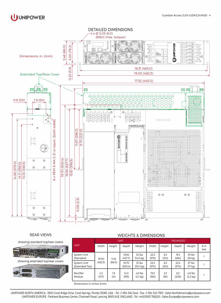
WEIGHTS & DIMENSIONS
UNIT
UNIT PACKAGED
Width Height Depth Weight Width Height Depth Weight # in box
System Unit (Standard) 19.00
(482.5)3.46
(88.0)
16.84(427.7)
32 lbs(14.5 kg)
22.5(570)
8.3(210)
19.3(490)
35 lbs(16 kg)
1
System Unit (Extended Top)
19.70(500.4)
33 lbs(15.0 kg)
22.5(570)
8.3(210)
22.5(570)
37 lbs(17 kg)
1
Rectifier Module
4.2(107)
1.6(41)
14.0(355)
4.6 lbs (2.1 kg)
15.5(394)
2.3(58)
8.2(208)
4.8 lbs(2.2 kg)
1
Dimensions in inches (mm)
0.0
9 (2
.5)
1.9 (50)
AC
-DC
Converter
FMPe30.48G
GU
AR
DIA
N 4
8
GU
AR
DIA
N 4
8G
UA
RD
IAN
48 C
B1C
B1C
B1C
B1C
B1C
B1
16ATR
IP
CU
RVE U
2
QY-1(13)-D
80V 10 KA 10
16ATR
IP
CU
RVE U
2
QY-1(13)-D
80V 10 KA 10
16ATR
IP
CU
RVE U
2
QY-1(13)-D
80V 10 KA 10
16ATR
IP
CU
RVE U
2
QY-1(13)-D
80V 10 KA 10
16ATR
IP
CU
RVE U
2
QY-1(13)-D
80V 10 KA 10
16ATR
IP
CU
RVE U
2
QY-1(13)-D
80V 10 KA 10
MER
LIN
GER
IN
mul
ti9C
120N
D10
0A41
5V~
1000
0
MER
LIN
GER
IN
mul
ti9C
120N
D10
0A41
5V~
1000
0
4 x Ø 0.25 (6.3) [6Nm max. torque]
3.0
0 (7
6.2
)
3.46
(88
.0)
0.2
3 (5
.9) 18.31 (465.0)
19.00 (482.5)
0.8 (20)
8 x
PE
M S
-M4-
2 Z
I or
equ
iv. [
bo
th s
ides
]
13.3
3 (3
38.5
)14
.11 (3
58.5
)14
.90
(378
.5)
17.52 (445.0)
19.7
0 (5
00
.4)
16.8
4 (4
27.7
)15
.61
(39
6.5
)
Dimensions: in. (mm)
Extended Top/Rear Cover11
.67
(29
6.3
)8
.70
(221
.0)
DETAILED DIMENSIONS
REAR VIEWS
showing standard top/rear covers
showing extended top/rear covers
UNIPOWER NORTH AMERICA • 3900 Coral Ridge Drive, Coral Springs, Florida 33065, USA • Tel: +1-954-346-2442 • Fax: +1-954-340-7901 • [email protected] EUROPE • Parkland Business Centre, Chartwell Road, Lancing, BN15 8UE, ENGLAND • Tel: +44(0)1903 768200 • [email protected]
gua
rdia
n_ac
cess
_2u2
4-d
s-re
vB-0
416.
ind
d
© 2016 UNIPOWER LLCThis document is believed to be correct at time of publication and UNIPOWER LLC accepts no responsibility for consequences from printing errors or inaccuracies. All specifications subject to change without notice.
Guardian Access 2U24 (GDN.S.24.M28) - 5
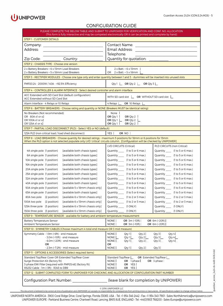
CONFIGURATION GUIDEPLEASE COMPLETE THE BELOW TABLE AND SUBMIT TO UNIPOWER FOR VERIFICATION AND CONF. NO. ALLOCATION
(This form is fully interactive and may be competed electronically OR it can be printed and complete by hand)
STEP 1 - CUSTOMER DETAILS
Company: _______________________________Address: _______________________________ _______________________________Zip Code: _________ Country: ____________
Contact Name: ________________________________Email Address: ________________________________ Telephone: ________________________________Quantity for quotation: __________
STEP 2 - CHASSIS TYPE - Choose one version
2 x Battery Breakers + 6 x 13mm Load Breakers2 x Battery Breakers + 5 x 18mm Load Breakers
2 x Batt. + 6 x 13mmOR 2 x Batt. + 5 x 18mm
STEP 3 - RECTIFIER MODULES - Choose one type only and enter quantity between 1 and 3 - dummies will be inserted into unused slots
FMP20.24 - 2000W / 40A - >92.5% Efficiency Qty 1 OR Qty 2 OR Qty 3
STEP 4 - CONTROLLER & ALARM INTERFACE - Select desired controller and alarm interface
ACC Extended with SD Card Slot (default configuration)ACC Extended without SD Card Slot
WITH SD card slot OR WITHOUT SD card slot
Alarm Interface - 4 Relays or 10 Relays 4 Relays OR 10 Relays
STEP 6 - BATTERY BREAKERS - Choose rating and quantity or NONE (Breakers MUST be identical rating)
No Breakers (Not recommended)OR 80A x1 or x2OR 100A x1 or x2OR 125A x1 or x2
NoneOR Qty 1 OR Qty 2OR Qty 1 OR Qty 2OR Qty 1 OR Qty 2
STEP 7 - PARTIAL LOAD DISCONNECT (PLD) - Select YES or NO (default)
125A PLD (non-critical load / load shed disconnect) YES OR NO
STEP 8 - LOAD BREAKERS - Choose quantity for desired ratings - maximum 5 positions for 18mm or 6 positions for 13mmWhen the PLD option is not selected populate only LVD ‘critical’ circuits column. [Configuration will be checked by UNIPOWER]
4A single pole (1 position) [available both chassis types]
6A single pole (1 position) [available both chassis types]
10A single pole (1 position) [available both chassis types]
16A single pole (1 position) [available both chassis types]
20A single pole (1 position) [available both chassis types]
25A single pole (1 position) [available both chassis types]
32A single pole (1 position) [available both chassis types]
40A single pole (1 position) [available both chassis types]
50A single pole (1 position) [available 5 x 18mm chassis only]
63A single pole (1 position) [available both chassis types]
80A two pole (2 position) [available 6 x 13mm chassis only]
100A two pole (2 position) [available 6 x 13mm chassis only]
125A three pole (3 position) [available 6 x 13mm chassis only]
150A three pole (3 position) [available 6 x 13mm chassis only]
LVD CIRCUITS (Critical)
Quantity ____ (1 to 5 or 6 max.)
Quantity ____ (1 to 5 or 6 max.)
Quantity ____ (1 to 5 or 6 max.)
Quantity ____ (1 to 5 or 6 max.)
Quantity ____ (1 to 5 or 6 max.)
Quantity ____ (1 to 5 or 6 max.)
Quantity ____ (1 to 5 or 6 max.)
Quantity ____ (1 to 5 or 6 max.)
Quantity ____ (1 to 5 or 6 max.)
Quantity ____ (1 to 5 or 6 max.)
Quantity ____ (1 to 2 or 3 max.)
Quantity ____ (1 to 2 or 3 max.)
Quantity ____ (1 ONLY)
Quantity ____ (1 ONLY)
PLD CIRCUITS (non Critical)
Quantity ____ (1 to 5 or 6 max.)
Quantity ____ (1 to 5 or 6 max.)
Quantity ____ (1 to 5 or 6 max.)
Quantity ____ (1 to 5 or 6 max.)
Quantity ____ (1 to 5 or 6 max.)
Quantity ____ (1 to 5 or 6 max.)
Quantity ____ (1 to 5 or 6 max.)
Quantity ____ (1 to 5 or 6 max.)
Quantity ____ (1 to 5 or 6 max.)
Quantity ____ (1 to 5 or 6 max.)
Quantity ____ (1 to 2 or 3 max.)
Quantity ____ (1 to 2 or 3 max.)
Quantity ____ (1 ONLY)
Quantity ____ (1 ONLY)
STEP 9 - TEMPERATURE SENSOR - available for battery and ambient temperature measurement
Battery Temperature SensorAmbient Temperature Sensor
NONE OR 3m (~10ft) OR 6m (~20ft)NONE OR 3m (~10ft) OR 6m (~20ft)
STEP 10 - SYMMETRY CABLES (Choose maximum 4 total end measure OR 3 mid measure)
Symmetry Cable - 1.9m (~6ft) - end measure - 3.0m (~10ft) - end measure - 6.0m (~20ft) - end measure OR - 2.3m (~7.2ft) - mid measure
NONE Qty 1 Qty 2 Qty 3 Qty 4NONE Qty 1 Qty 2 Qty 3 Qty 4NONE Qty 1 Qty 2 Qty 3 Qty 4ORNONE Qty 1 Qty 2 Qty 3
STEP 11 - OPTIONS & ACCESSORIES (Select required items)
Standard Top/Rear Cover OR Extended Top/Rear CoverSurge Protection Kit (factory fit)3-phase EMI Filter [required with FMP25.48] (factory fit)RS232 Cable - 1m (~3ft) - RJ45 to DB9
Standard Top/Rear OR Extended Top/RearNONE OR 1-phase OR 3-phaseNONE OR YESNONE OR YES
STEP 12 - SUBMIT COMPLETED FORM TO UNIPOWER FOR CHECKING AND ALLOCATION OF CONFIGURATION PART NUMBER
Configuration Part Number: __________________ (leave blank for completion by UNIPOWER)