Embed Size (px)
Citation preview

APRIL 2016TECHNICAL BROCHURE
gtekplasterboard.com.au WET AREASOLUTIONS
GTEKTM WET AREA GTEKTM FIRE & WET AREA

CONTENTS
GTEKTM WET AREAPAGE__04. Product Information PAGE__04. Early Fire Indices PAGE__04. Fire Resistance PAGE__04. Dimensional Stability PAGE__04. Thermal Insulation PAGE__04. Handling and Storage PAGE__04. Sheet Sizes and WeightPAGE__05. InstallationPAGE__06. Tiled WallsPAGE__06. Pre-formed Shower Base and External Shower trayPAGE__07. PenetrationsPAGE__07. Insitu Shower Tray PAGE__08. Shower over Bath PAGE__09. Structural MovementsPAGE__09. Control JointsPAGE__10. Corner JointingPAGE__10. JointingPAGE__16. Australian Standards - Wet AreasPAGE__18. Exterior CeilingsPAGE__19. External Considerations
GTEKTM FIRE & WET AREAPAGE__21. Product Information PAGE__21. Fire Resistance PAGE__21. Dimensional Stability PAGE__21. Thermal Properties PAGE__21. Installation PAGE__21. Sheet Size and Weight
PAGE__05. GECA PAGE__08. Warranty
GTEKTM WET AREA
TECHNOLOGY
SUSTAINABILITY
AUSTRALIAN MADE
SERVICE
QUALITY
SYSTEMS
WHY GTEKTM?
WITH OUR ALL-AUSTRALIAN GTEK™ RANGE OF INTERIOR LINING PRODUCTS, YOU BENEFIT FROM SUSTAINABLE, QUALITY-TESTED TECHNOLOGY, FULL BGC INTERIOR LINING SYSTEMS COMPATIBILITY AND OUR CLASS-LEADING SERVICE NETWORK.
TECHNOLOGY / Light, modular GTEKTM technology eases installation for seamless results
SUSTAINABILITY / GECA certified: sustainable manufacture means higher Green Star ratings for your building
AUSTRALIAN MADE / All-Australian: closest available links between local manufacture and supply
SERVICE / Vast distribution network assures best-in-class service delivery
QUALITY / Independent testing accords with Australia’s toughest build-quality accreditations
SYSTEMS / Full compatibility with extensive BGC interior lining systems range

GTEKTM WET AREA PAGE __ 03. gtekplasterboard.com.au
GTEKTM Wet Area has a low absorption core that eliminates the probability of water wicking, therefore preventing possible damage to the supporting structure and wall finishes.What’s good about GTEK™ Wet Area:
Specifically designed for wet areas Has a low absorption core Light blue face for ease of identification Quick and simple to install Can be used for exterior ceilings
GTEKTM Wet Area has been designed and developed for wet area walls in residential and commercial buildings. Suitable for bathrooms, laundries,toilets, cleaning room areas and exterior ceilings such as alfresco areas.
GTEKTM WET AREA
BGC-2014GECA 04-2011 v2
Panel Boards
GTEKTM WET AREA PAGE __ 04. gtekplasterboard.com.au
DIMENSIONAL STABILITY
THERMAL PROPERTIES
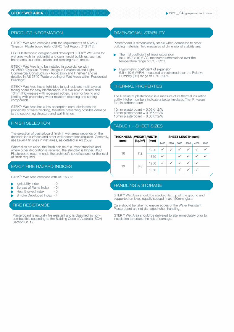
TABLE 1 – SHEET SIZES
HANDLING & STORAGE
The R value of plasterboard is a measure of its thermal insulation ability. Higher numbers indicate a better insulator. The ‘R’ values for plasterboard are:
10mm plasterboard = 0.05Km2/W13mm plasterboard = 0.05Km2/W16mm plasterboard = 0.06Km2/W
GTEKTM Wet Area should be stacked flat, up off the ground and supported on level, equally spaced (max 450mm) gluts.
Care should be taken to ensure edges of the Water Resistant Plasterboard are not damaged when handling.
GTEKTM Wet Area should be delivered to site immediately prior to installation to reduce the risk of damage.
PRODUCT INFORMATION
FINISH SELECTION
EARLY FIRE HAZARD INDICES
FIRE RESISTANCE
GTEKTM Wet Area complies with the requirements of AS2588 ‘Gypsum Plasterboard’(refer CSIRO Test Report DTS 713).
BGC Plasterboard designed and developed GTEKTM Wet Area for wet area walls in residential and commercial buildings, such as bathrooms, laundries, toilets and cleaning room areas.
GTEKTM Wet Area is to be installed in accordance with AS 2589 “Gypsum Plaster Linings in Residential and Light Commercial Construction - Application and Finishes” and as detailed in AS 3740 “Waterproofing of Wet Areas within Residential Buildings”.
GTEKTM Wet Area has a light-blue fungal resistant multi-layered facing board for easy identification. It is available in 10mm and 13mm thicknesses with recessed edges, ready for taping and jointing with proprietary water resistant stopping and setting compounds.
GTEKTM Wet Area has a low absorption core, eliminates the probability of water wicking, therefore preventing possible damage to the supporting structure and wall finishes.
The selection of plasterboard finish in wet areas depends on the desired tiled surfaces and other wall decorations required. Generally, use Level 4 finishes in wet areas, as detailed in AS 2589.
Where tiles are used, the finish can be of a lower standard and where other decoration is required, the standard is higher. BGC Plasterboard recommends the architect’s specifications for the level of finish required.
GTEKTM Wet Area complies with AS 1530.3
Ignitability Index - 0 Spread of Flame Index - 0 Heat Evolved Index - 0 Smoke Developed Index - 4
Plasterboard is naturally fire resistant and is classified as non-combustible according to the Building Code of Australia (BCA) Section C1.12.
Plasterboard is dimensionally stable when compared to other building materials. Two measures of dimensional stability are:
Thermal coefficient of linear expansion (a) = 16.7 x 10⁻⁶ /˚C, measured unrestrained over the temperature range of 3˚C - 32˚C
Hygrometric coefficient of expansion 6.5 x 10⁻⁶ /%RH, measured unrestrained over the Relative Humidity (RH) range of 10% - 90%
THICKNESS (mm)
WEIGHT (kg/m2)
WIDTH (mm)
SHEET LENGTH (mm)
1200
1350
1200
1350
2400
ü
ü
ü
2700
ü
ü
3000
ü
ü
ü
ü
3600
ü
ü
ü
ü
4200
ü
ü
ü
ü
4800
ü
ü10
13
7.2
8.8
GTEKTM WET AREA PAGE __ 05. gtekplasterboard.com.au
INSTALLATION
FRAMING
FIXING
TABLE 3 - NON-TILED AREA FIXING
TABLE 2-MINIMUM SCREW FASTENER LENGTH AND TYPE
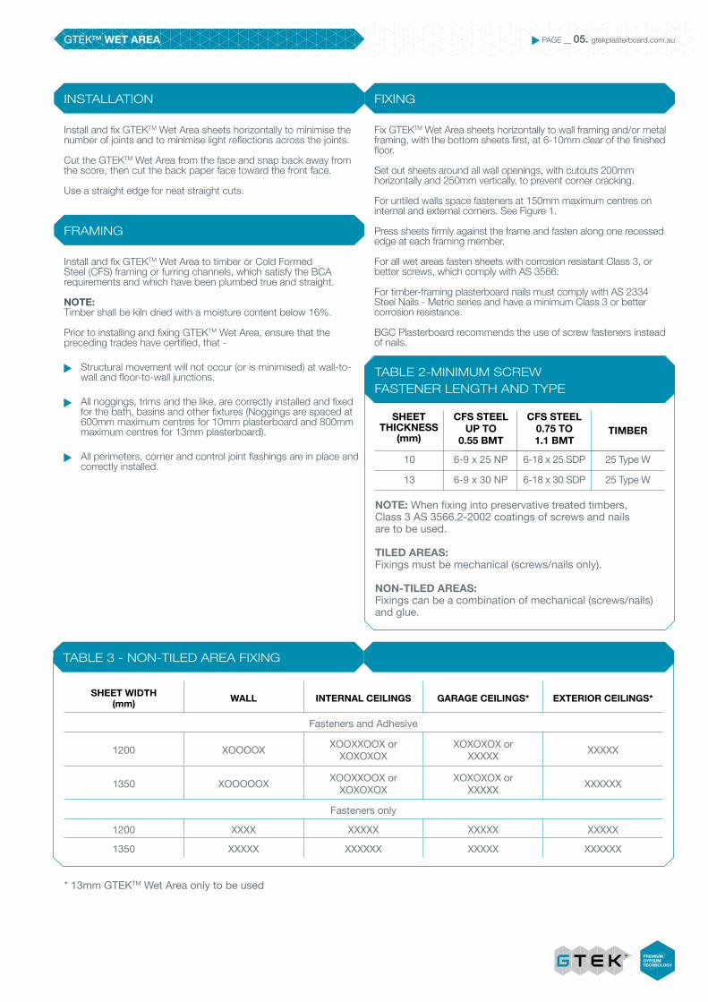
Install and fix GTEKTM Wet Area sheets horizontally to minimise the number of joints and to minimise light reflections across the joints.
Cut the GTEKTM Wet Area from the face and snap back away from the score, then cut the back paper face toward the front face.
Use a straight edge for neat straight cuts.
Install and fix GTEKTM Wet Area to timber or Cold Formed Steel (CFS) framing or furring channels, which satisfy the BCA requirements and which have been plumbed true and straight.
NOTE: Timber shall be kiln dried with a moisture content below 16%.
Prior to installing and fixing GTEKTM Wet Area, ensure that the preceding trades have certified, that -
Structural movement will not occur (or is minimised) at wall-to-wall and floor-to-wall junctions.
All noggings, trims and the like, are correctly installed and fixed for the bath, basins and other fixtures (Noggings are spaced at 600mm maximum centres for 10mm plasterboard and 800mm maximum centres for 13mm plasterboard).
All perimeters, corner and control joint flashings are in place and correctly installed.
Fix GTEKTM Wet Area sheets horizontally to wall framing and/or metal framing, with the bottom sheets first, at 6-10mm clear of the finished floor.
Set out sheets around all wall openings, with cutouts 200mm horizontally and 250mm vertically, to prevent corner cracking.
For untiled walls space fasteners at 150mm maximum centres on internal and external corners. See Figure 1.
Press sheets firmly against the frame and fasten along one recessed edge at each framing member.
For all wet areas fasten sheets with corrosion resistant Class 3, or better screws, which comply with AS 3566:
For timber-framing plasterboard nails must comply with AS 2334 Steel Nails - Metric series and have a minimum Class 3 or better corrosion resistance.
BGC Plasterboard recommends the use of screw fasteners instead of nails.
NOTE: When fixing into preservative treated timbers,Class 3 AS 3566.2-2002 coatings of screws and nailsare to be used.
TILED AREAS: Fixings must be mechanical (screws/nails only).
NON-TILED AREAS: Fixings can be a combination of mechanical (screws/nails) and glue.
SHEET THICKNESS
(mm)
CFS STEELUP TO
0.55 BMT
CFS STEEL0.75 TO 1.1 BMT
TIMBER
10
13
6-9 x 25 NP
6-9 x 30 NP
6-18 x 25 SDP
6-18 x 30 SDP
25 Type W
25 Type W
SHEET WIDTH (mm) WALL INTERNAL CEILINGS GARAGE CEILINGS* EXTERIOR CEILINGS*
Fasteners and Adhesive
1200 XOOOOX XOOXXOOX or XOXOXOX
XOXOXOX or XXXXX XXXXX
1350 XOOOOOX XOOXXOOX or XOXOXOX
XOXOXOX or XXXXX XXXXXX
Fasteners only
1200 XXXX XXXXX XXXXX XXXXX
1350 XXXXX XXXXXX XXXXX XXXXXX
* 13mm GTEKTM Wet Area only to be used

GTEKTM WET AREA PAGE __ 06. gtekplasterboard.com.au
TILED WALLS
PRE-FORMED SHOWER BASE AND EXTERNAL SHOWER TRAY
Position fasteners between 10mm and 16mm from the edge of the sheets at the correct spacing to carry the loads of the tiles.
For walls with tiles 6.5mm thick or 12.5 kg/m2 or less, space fasteners at 200mm maximum centres on the intermediate studs and at 150mm on internal and external corners, butt joints and around openings.
Where tiles are greater than 6.5mm thick and/or up to 32 kg/m2, space all fasteners at 100mm maximum centres in the centre of sheets, on internal and external corners, butt joints and around openings.
BGC Plasterboard recommends waterproof membrane be used in wet areas 150mm around bath and 150mm above vanity as shown in figures 13, 14 and 15.
Tile adhesive should be compatible with the waterproofingmembrane.
Preliminary work and detail fixing out is similar for external shower trays and preformed shower bases, as shown in Figure 2.
Install and fix perimeter-flashing angles, at the wall/ floorjunction and pre-formed shower bases or external showertrays, prior to fixing GTEKTM Wet Area.
Cut and install PVC corner angle, down inside the pre-formedshower base; Figure 9 and fasten to framing at 600mm centres, in a staggered pattern.
Seal the lower edge of GTEKTM Wet Area sheets, whethercut or not, with a proprietary wet-area acrylic sealant or silicone to prevent potential moisture wicking.
Install and fix sheets to the wall framing 6mm clear of the shower tray up-stand; See Figure 2 and of the mortar bed in the external shower tray.
Caulk the bottom edge of the sheets and the shower base or the mortar bed and around plumbing fixtures with a flexible sealant. See Figures 2 & 3.
TABLE 4 – FASTENER SPACING IN TILED AREAS
WALL TILE WEIGHT (INCL. TILE ADHESIVE)
MAX. FASTENER SPACING
Intermediate Studs
200mm
100mm
Sheet Ends
150mm
100mm
No greater than 12kg/m²
Greater than 12kg/m² up to 32kg/m²
Timber or steel wall frame (typical)
GTEKTM Wet Area
FIGURE 1 – SHEET SET OUT UNTILED AREAS
Refer to Table 3
Refer to Table 3
Set sheet 10mm clear of floor
Secure sheet edges at each stud
FIGURE 2 – PRE-FORMED SHOWER BASE
GTEKTM Wet Area
Ceramic Wall Tiles
Timber Framing
Nogging set 25mm above shower base for fixing lower edge of the GTEKTM Wet Area
Notch framing to accommodate shower base
Flexible Sealant
Gap 6mm
Pre-formed Shower Base

GTEKTM WET AREA PAGE __ 07. gtekplasterboard.com.au
INSITU SHOWER TRAY
Install and fix perimeter-flashing angles, at the wall/floorjunction.
Cut and install PVC corner angle and fasten to framing at 600mm centres, in a staggered pattern.
Seal the lower edge of water resistant plasterboard sheets, whether cut or not, with a proprietary wet-area acrylic sealant to prevent potential moisture wicking.
Install and fix sheets to the wall framing, as outlined previously, 6mm clear off the floor.
Form a bond-breaker with closed-cell foam backing rod and masking tape at the bottom edge of the plasterboard at wall/floor junction, as shown in Figure 4.
Caulk around plumbing penetrations.
Apply a proprietary liquid membrane material to the face of the plasterboard and floor to form an insitu internal shower tray.
Follow the membrane manufacturer’s instructions.
Apply the membrane to the entire shower area to a minimum height of 1800mm from the finished floor surface. The liquid membrane is to extend 75mm minimum each side of the corner to a minimum of 50mm above shower rose.
Note: Use only insitu membrane materials appraised and approved by recognised authorities.
FIGURE 4 – INSITU SHOWER BASEWall framing
Corner flashing
GTEKTM Wet Area
Liquid Membrane
Wall tiling to builder’s specification
Mortar bed
BGC Compressed Flooring or DurafloorTM
Bond breaker
Masking tape (includes bond breaker tape in position)
Flexible sealantPerimeter flashing
Paper tape using GTEKTM Water Resistant Taping Cement or BGC Exterior and Wet Area Base Coat
PENETRATIONS
GTEKTM Wet Area must be cut out to leave a 6mm gap all round the fixture. This gap must be filled with a mould resistant flexible sealant.
BGC recommends using a hole saw to make a neat cut out for fittings such as taps, shower roses etc. Do not use a hammer.
Additional framing must be installed as required to properly support all fixtures.
FIGURE 3 – SEALING PENETRATIONS
Timber Framing
GTEKTM Wet Area
Ceramic Tiles
Install nogging as necessary to support fittings
Silicone Sealant (6mm gap all round)
To form neat holes for penetrations in GTEKTM Wet Area a hole saw is recommended

GTEKTM WET AREA PAGE __ 08. gtekplasterboard.com.au
SHOWER OVER BATH
Preliminary work and fixing out detail is similar for pre-formed shower bases and in part the insitu tray details, see Figure 5.
Cut and install PVC corner angle, down inside the bath up-stand flange and fasten to framing at 600mm centres, in a staggerd pattern, see Figure 6.
Seal the lower edge of water resistant plasterboard sheets, whether cut or not, with a proprietary wet-area acrylic sealant, to prevent potential moisture wicking.
Install and fix sheets to the wall framing, as outlined previously 6mm clear off the bath up-stand.
Caulk the bottom edge of the sheets and the bath edge around plumbing fixtures with a mould resistant flexible sealant.
Apply a proprietary branded liquid membrane 150mm above the bath edge and wall surround, to a minimum height of 1800mm to the entire area above the finished floor level and 75mm each side of the corner to a minimum of 50mm above shower rose, see Figure 5 & 6.
FIGURE 6 – BATH WITHOUT SHOWERCorner blocking
GTEKTM Wet Area
Wall tiling to builder’s specification
Bath
Additional timber traming required
Notch framing to accommodate bath rim
Flexible sealant required
Flexible sealant required
Corner flashing required to bath base
FIGURE 5 – SHOWER OVER BATH
GTEKTM Wet Area
Flexible sealant along bath/shower joint
Waterproofing 1800mm above base of bath and 50mm above shower rose
Seal tap set penetrations using mould resistant flexible sealant

GTEKTM WET AREA PAGE __ 09. gtekplasterboard.com.au
STRUCTURAL MOVEMENTS
Buildings and their component parts move over time due to various factors which may lead to building and or system failures if design, materials and/or installation are not satisfactory.
To minimise the risk of system failure take care when designing, detailing, installing and finishing all aspects of wet areas.
The design of wet areas must take into account any relative movements in the building structure and components, due to loading and temperature and humidity variations and the like. See Figure 7.
FIGURE 7 – STRUCTURAL MOVEMENTSWall Framing
Corner Flashing
GTEKTM Wall
Liquid Membrane
Bond Breaker
Flashing
Masking Tape
Mortar Bed
BGC Compressed Flooring or DurafloorTM
CONTROL JOINTS
CORNER JOINTING
In long runs of wall, control joints should be set at 7.2 metres maximum in non-tiled areas, and at 4.2 metres maximum, in tiled areas or at construction joints, whichever is the lesser. Control joints must allow for the differential expansion and contraction between the structure, wall lining and tiles. Control joints must be constructed with double studs, with a gap to suit the control joint type. Refer Figure 8.
Corners are set and finished with paper tapes in wet areas for internal corners, or external beads for external corners.
However, in wet area construction, corners above pre-formed shower bases, insitu trays and shower over bath situations require special attention to detail, as noted.
FIGURE 8 – CONTROL JOINTS
Additional studwork
GTEKTM Wet Area
Rondo P35 Control joint or MBS P45 Jointing kit installed to manufacturer’s recommendation
Flush finish with bedding cement – Keep joint clean of flushing material
15mm gap
Wall framing – lightweight steel or timber (typical)

GTEKTM WET AREA PAGE __ 10. gtekplasterboard.com.au
VERTICAL CORNER FLASHING
In tiled walls, vertical corner flashings finish inside pre-fabricated shower tray/base, insitu-laid trays or the like. Refer Figure 9.
NOTE: GTEKTM Water Resistant Taping Cement to be used under tiled areas only.
BGC Exterior and Wet Area Base Coat may be used in tiled and untiled areas.
GTEKTM Base Coat may be used in tiled and untiled areas.
BGC Exterior and Wet Area Top Coat to be used in untiled areas only.
FIGURE 9 – VERTICAL CORNER FLASHING
GTEKTM Wet Area
Perimeter angle flashing
Hob is formed inside shower tray
Floor tiles to builder’s specification
Pre-fabricated shower tray
Mould resistant flexible sealant
Rondo P40 vertical corner angle flashing (40x40 nominal or PVC 50x50)
Liquid Membrane
FIGURE 9a – CONTROL JOINTS
Shower screen
Tiled hob
25mm minimum
Floor tiling to builder’s specification
Prefabricated shower tray
Mortar bed
Concrete slab

GTEKTM WET AREA PAGE __ 11. gtekplasterboard.com.au
JOINTING TABLE 5 – TILED AREAS
TABLE 7 – NON-TILED AREAS – FINISH COAT
TABLE 6 – TILED AREAS – NON-WET AREAS
FIRSTCOAT
FIRSTCOAT
FIRSTCOAT
GTEKTM Water Resistant Taping
Cement or BGC Exterior and
Wet Area Base Coat or GTEKTM
Base Coat.
BGC Exterior and Wet Area Base Coat or GTEKTM
Base Coat.
GTEKTM
Base Coat.
GTEKTM Water Resistant Taping
Cement or BGC Exterior and
Wet Area Base Coat
or GTEKTM
Base Coat.
BGC Exterior and Wet Area Base Coat or GTEKTM
Base Coat.
GTEKTM
Base Coat.
None Required
GTEKTM
Multupurpose Joint
Compound or GTEKTM
All Purpose Lightweight or GTEKTM
Top Coat
None Required
Perforated Paper Tape
Perforated Paper Tape
Perforated Paper Tape
TAPE
TAPE
TAPE
SECONDCOAT
SECONDCOAT
SECONDCOAT
FINISHCOAT
FINISHCOAT
FINISHCOAT
Wet area plasterboard joints must satisfy the BCA requirements and comply with AS 2589.
All GTEKTM Wet Area joints in wet areas must be set with perforated paper tapes and proprietary branded base and flushing compounds such as GTEKTM Water Resistant Taping Cement, GTEKTM Base Coat, BGC Exterior and Wet Area Base Coat and Top Coat outside tiled areas.
The wet area base-coat system is typically a two-coat system under tiled areas and a three-coat system where tiles are not used. Refer Tables 5, 6 and 7.
All horizontal, vertical and corner joints and fastener points must be stopped and set with the same materials, to ensure water resistance across the wall areas.
The use of correct materials, application and sequencing of taping and jointing is important and any deviation may result in joint failure.
Mixing of different proprietary compounds or application of setting type compounds over acrylic drying compounds may lead to joint failure and will negate any proprietary item warranties.
NOTE: Do not use setting type compounds over water-resistant acrylic drying type compounds.
Do not use self adhesive tapes. Paper Tape only to be used.

GTEKTM WET AREA PAGE __ 12. gtekplasterboard.com.au
FIRST COAT AND TAPE
SECOND COAT
FINISH COAT
SANDING AND FINISHING
Wipe joint recesses with damp cloth to remove dust from plasterboard face.
Fully fill recess evenly with GTEKTM Water Resistant Taping Cement or GTEKTM Base Coat.
Centrally bed the paper tape into bed coat and cover lightly with GTEKTM Water Resistant Taping Cement or BGC Exterior and Wet Area Base Coat and allow to fully dry.
Cover all fastener points with GTEKTM Water Resistant Taping Cement or BGC Exterior and Wet Area Base Coat and allow to fully dry.
Apply the second coat of GTEKTM Water Resistant Taping Cement or BGC Exterior and Wet Area Base Coat 180mm wide and feather out the edges and allow to fully dry.
Apply a second coat to all fastener points, feather out 25mm and allow to fully dry.
The above is applicable for both tiled and non-tiled areas (Level 4 Finish).
First coat and second coat only required for tiles areas.
The finish coat is only required where tiles are not used and another decorative finish is required. Eg Level 4 Finish.
Apply a 280mm wide approximate, thin finish coat, centrally over the second coat.
Dampen the outer edges with a sponge to feather out the edges of the finish coat and allow to dry.
Apply a thin finish coat over all fastener points and feather out 40mm and allow to dry
Allow joint and fastener point coating compounds to dry for 24 hrs before sanding.
For tiled areas lightly sand all joints and fastener points, with 150 grit or with 220 sanding mesh, to remove any high spots.
Wipe off excess dust with a slightly damp cloth prior to the application of tile adhesive, seal coats or decorative finishes.
FIGURE 10 - FIRST COAT (100MM APPROX)
FIGURE 11 – (180MM APPROX)
FIGURE 12 – TOPPING COAT (250MM APPROX)
FIGURE 13 – FINISHING SANDING
1. Fill recess
3. Lightly cover paper tape
2. Install paper tape over joint centre line
Allow 24 hours min drying time then lightly sand joint

GTEKTM WET AREA PAGE __ 13. gtekplasterboard.com.au
AUSTRALIAN STANDARDS WET AREAS
The following tables are the specific requirements for Wet Areas taken from the Australian Standards 3740-2010 and are applicable to areas lined with GTEKTM Wet Area.
“An area within a building supplied with water from a water supply system and includes bathrooms, showers, laundries and sanitary compartments. Excludes kitchens, bar areas, kitchenettes or domestic food and beverage preparation areas”.
The BCA requires that all wet-area design, construction and materials do not create unhealthy, dangerous conditions, or damage to building components, caused by dampness, water overflow, infiltration or penetration.
GTEKTM Wet Area
Flexible sealant along bath/shower joint
Waterproofing 1800mm above base of bath and 50mm above shower rose
Seal tap set penetrations using mould resistant flexible sealanf
FIGURE 14 – WATERPROOFING – SHOWER OVER BATH

GTEKTM WET AREA PAGE __ 14. gtekplasterboard.com.au
TABLE 8 - DESIGN AND INSTALLATION FOR WET AREA WATERPROOFING AS3740-2010
Waterproof*
N/A
N/A
Horizontal surface
Waterproof*Vertical surfaceWater resistant
Horizontal surface
Waterproof*Vertical surfaceWater resistant
Horizontal sur-face Waterproof*Vertical surfaceWater resistant
N/A
Waterproof where through the floor,
otherwise N/A
Vessels or area where the fixture is installed Level of risk
High
Medium
Medium
Low
Low
High
Shower area
Bathrooms
Areas adjacent to baths & spas§ (applies to all rooms in
which a bath or spa is installed)
Walls adjoining other vessels (e.g., sink, basin or laundry tubs)
Laundries & WCs
Bathrooms & laundries requiring a floor waste in accordance with Volume One of the BCA
Floor
Waterproofed & drained
Concrete & compressed fibre cement sheet flooring
Water resistant‡
Timber floors including
particleboard, plywood &
other materialsWaterproof
Concrete & compressed fibre cement sheet flooring
Water resistant‡
Timber floors including
particleboard, plywood &
other materialsWaterproof
N/A
Water resistant‡
Waterproofed and drained
Water proof
N/A
N/A
Water resistant§
Water resistant§
Water resistant
N/A
N/A
Waterproof
Waterproof¥
Waterproof¥
Waterproof
Waterproof
Waterproof
Water resistant¥
Waterproof¥
14
13, 15
13, 15
15
Walls Junctions
Design and installation criteria
Penetrations Figure No.
LEGEND:
N/A Not Applicable
* Including mechanical fixings or fasteners through surface materials
¥ Wall/floor junctions only
‡ Where floor waste is provided the floor shall be graded to the waste
§ If a shower is included in a bath, include the requirements for shower area walls
VESSELS OR AREA WHERE THE FIXTURE IS INSTALLED
LEVEL OF RISK
DESIGN AND INSTALLATION CRITERIA
FLOOR WALLS JUNCTIONS PENETRATIONS FIGURE NO.
15
14, 16
14, 16
16
GTEKTM WET AREA PAGE __ 15. gtekplasterboard.com.au
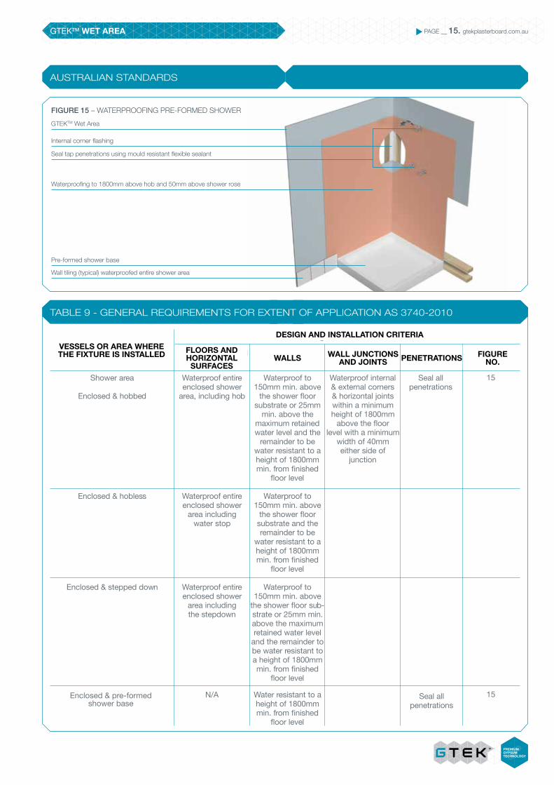
TABLE 9 - GENERAL REQUIREMENTS FOR EXTENT OF APPLICATION AS 3740-2010
AUSTRALIAN STANDARDS
GTEKTM Wet Area
Seal tap penetrations using mould resistant flexible sealant
Internal corner flashing
Waterproofing to 1800mm above hob and 50mm above shower rose
Wall tiling (typical) waterproofed entire shower area
Pre-formed shower base
FIGURE 15 – WATERPROOFING PRE-FORMED SHOWER
Seal all penetrations
Seal all penetrations
Vessels or area where the fixture is installed
Shower area
Enclosed & hobbed
Enclosed & hobless
Enclosed & stepped down
Enclosed & preformed shower base
Floors & horizontal surfaces
Waterproof entire enclosed shower
area, including hob
Waterproof entire enclosed shower
area including water stop
Waterproof entire enclosed shower
area including the stepdown
N/A
Waterproof to 150mm min. above
the shower floor substrate or 25mm
min. above the maximum retained water level and the
remainder to be water resistant to a height of 1800mm min. from finished
floor level
Waterproof to 150mm min. above
the shower floor substrate and the remainder to be
water resistant to a height of 1800mm min. from finished
floor level
Waterproof to 150mm min. above
the shower floor sub-strate or 25mm min. above the maximum retained water level
and the remainder to be water resistant to a height of 1800mm min. from finished
floor level
Water resistant to a height of 1800mm min. from finished
floor level
Waterproof internal & external corners & horizontal joints within a minimum height of 1800mm
above the floor level with a minimum
width of 40mm either side of
junction
14
14
Walls Wall junctions & joints
Design and installation criteria
Penetrations Figure No.VESSELS OR AREA WHERE THE FIXTURE IS INSTALLED
DESIGN AND INSTALLATION CRITERIA
FLOORS AND HORIZONTAL
SURFACESWALLS PENETRATIONS FIGURE
NO.WALL JUNCTIONS
AND JOINTS
15
15Enclosed & pre-formed shower base
GTEKTM WET AREA PAGE __ 16. gtekplasterboard.com.au
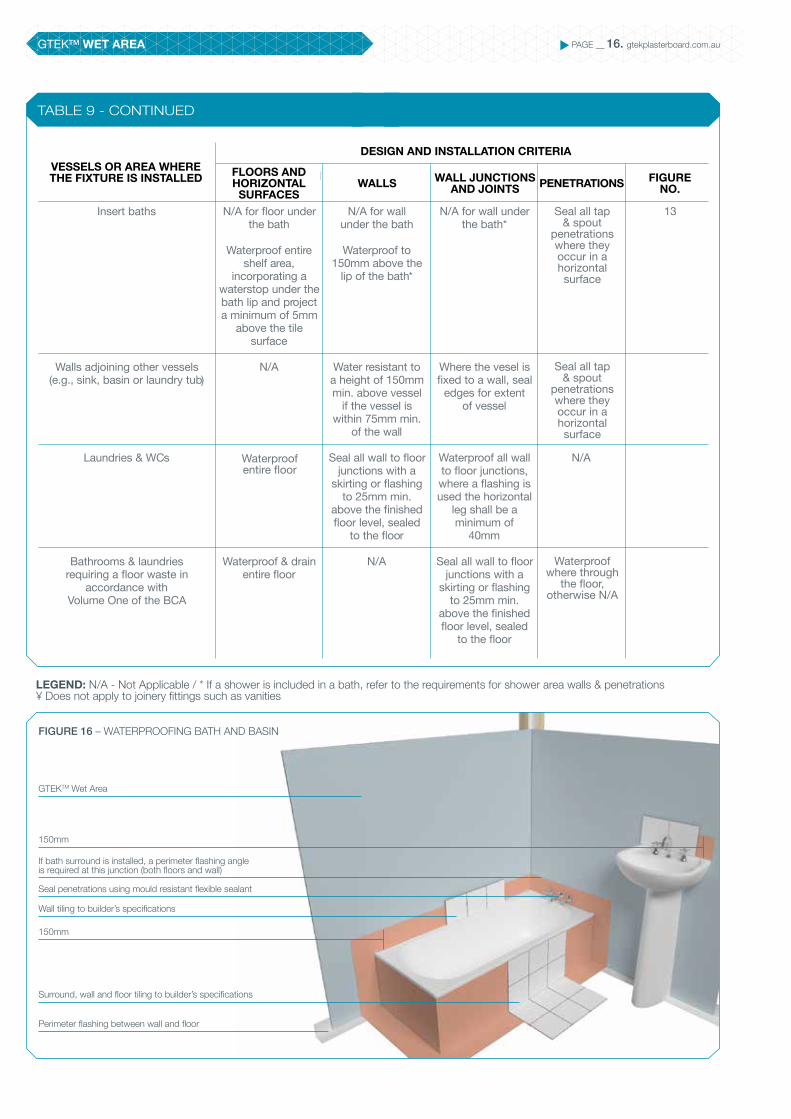
TABLE 9 - CONTINUED
N/A
Vessels or area where the fixture is installed
Insert baths
Walls adjoining other vessels (e.g., sink, basin or laundry tub)
Laundries & WCs
Bathrooms & laundries requiring a floor waste in
accordance with Volume One of the BCA
Floors & horizontal surfaces
N/A for floor under the bath
Waterproof entire shelf area,
incorporating a waterstop under the bath lip and project a minimum of 5mm
above the tile surface
N/A
Waterproof & drain entire floor
N/A for wall under the bath
Waterproof to 150mm above the
lip of the bath*
Water resistant to a height of 150mm min. above vessel
if the vessel is within 75mm min.
of the wall
Seal all wall to floor junctions with a
skirting or flashing to 25mm min.
above the finished floor level, sealed
to the floor
N/A
N/A for wall under the bath*
Where the vesel is fixed to a wall, seal
edges for extent of vessel
Waterproof all wall to floor junctions, where a flashing is used the horizontal
leg shall be a minimum of
40mm
Seal all wall to floor junctions with a
skirting or flashing to 25mm min.
above the finished floor level, sealed
to the floor
13
Walls Wall junctions & joints
Design and installation criteria
Penetrations Figure No.
Seal all tap & spout
penetrations where they occur in a horizontal surface
Seal all tap & spout
penetrations where they occur in a horizontal surface
Waterproof where through
the floor, otherwise N/A
GTEKTM Wet Area
Wall tiling to builder’s specifications
Seal penetrations using mould resistant flexible sealant
If bath surround is installed, a perimeter flashing angle is required at this junction (both floors and wall)
Surround, wall and floor tiling to builder’s specifications
150mm
150mm
Perimeter flashing between wall and floor
FIGURE 16 – WATERPROOFING BATH AND BASIN
Waterproof entire floor
LEGEND: N/A - Not Applicable / * If a shower is included in a bath, refer to the requirements for shower area walls & penetrations ¥ Does not apply to joinery fittings such as vanities
essels or area where the e is installed Floors & horizontal
surfacesWalls Wall junctions
& joints
Design and installation criteria
Penetrations Figure No.VESSELS OR AREA WHERE THE FIXTURE IS INSTALLED
DESIGN AND INSTALLATION CRITERIA
FLOORS AND HORIZONTAL
SURFACESWALLS PENETRATIONS FIGURE
NO.WALL JUNCTIONS
AND JOINTS

GTEKTM WET AREA PAGE __ 17. gtekplasterboard.com.au
TABLE 9 - CONTINUED
BGC Plasterboard wishes to acknowledge and recommend treatment and installation of wet areas as per the Australian Standards
Waterproof internal and external corners and horizontal joints to a minimum height of 1800mm above the floor level with a minimum width
of 40mm either side of junction
Waterproof all wall to floor junctions, where a flashing is used the horizontal leg shall be a mini-mum of of 40mm
Waterproof all wall to floor junctions, where a flashing is used the horizontal
leg shall be a minimum of 40mm
Seal edges for extent of vessel
and junction of bath enclosure with floor. Where the lip of the bath is supported
by a horizontal surface this area
shall be waterproof for showers over bath
and water resist for all other cases
Seal edges for extent of vessel
and junction of bath enclosure with floor. Where the lip of the bath is supported by a horizontal surface
this area shall be waterproof for
showers over bath and water resist for
all other cases
Seal all penetrations
N/A
N/A
Seal all tap and spout penetrations where they occur
in a horizontal surface
Seal all tap and spout penetrations where they occur
in a horizontal surface
Waterproof to 150mm min. above
the shower floor substrate or 25mm
min. above the maximum retained water level and the
remainder to be water resistant to a height of 1800mm min. from finished
floor level
N/A
N/A
Water resistant to a height of 150mm min. above vessel
and exposed surfaces below
vessel lip to floor level*
Water resistant to a height of 150mm min.
above vessel and exposed surfaces below vessel lip to
floor level*
Vessels or area where the fixture is installed
Unenclosed
Areas outside the shower area for concrete and
compressed fibre cement sheet flooring
Areas outside the shower area for timber floors including
particleboard, plywood and other flooring materials
Areas adjacent to baths and spa*¥ for concrete and
compressed fibre cement sheet flooring
Areas adjacent to baths and spas*¥ for timber floors including
particleboard, plywood and other flooring materials
Floors & horizontal surfaces
Waterproof entire shower area
Water resistant to entire floor
Waterproof entire floor
Water resistant to entire floor
Waterproof entire floor
13
13
Walls Wall junctions & joints
Design and installation criteria
Penetrations Figure No.essels or area where the
e is installed Floors & horizontal surfaces
Walls Wall junctions & joints
Design and installation criteria
Penetrations re No.VESSELS OR AREA WHERE THE FIXTURE IS INSTALLED
DESIGN AND INSTALLATION CRITERIA
FLOORS AND HORIZONTAL
SURFACESWALLS PENETRATIONSWALL JUNCTIONS
AND JOINTSFIGURE
NO.
Waterproof entire floor
Areas outside the shower area for timber floors including particleboard, plywood,
compressed flooring and other flooring materials
Areas adjacent to baths and spa*¥ for timber floors including
particleboard, plywood, compressed flooring and other
flooring materials
GTEKTM WET AREA PAGE __ 18. gtekplasterboard.com.au
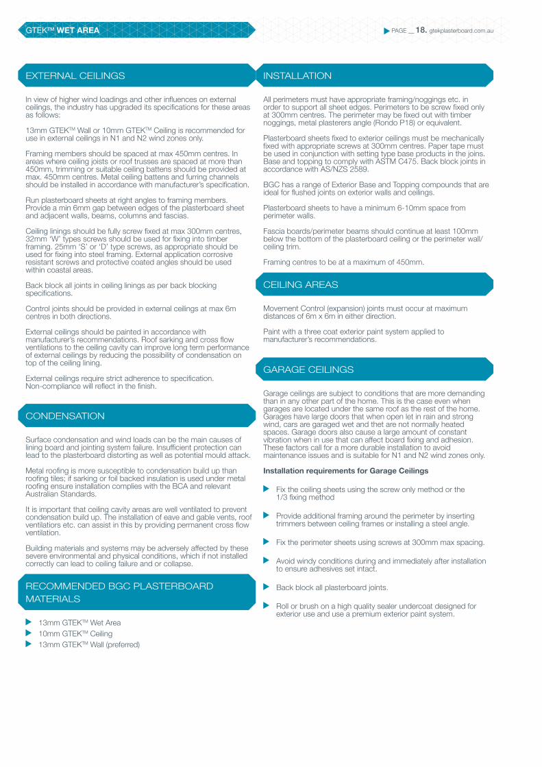
EXTERNAL CEILINGS
CONDENSATION
RECOMMENDED BGC PLASTERBOARD MATERIALS
INSTALLATION
CEILING AREAS
GARAGE CEILINGS
In view of higher wind loadings and other influences on external ceilings, the industry has upgraded its specifications for these areas as follows:
13mm GTEKTM Wall or 10mm GTEKTM Ceiling is recommended for use in external ceilings in N1 and N2 wind zones only.
Framing members should be spaced at max 450mm centres. In areas where ceiling joists or roof trusses are spaced at more than 450mm, trimming or suitable ceiling battens should be provided at max. 450mm centres. Metal ceiling battens and furring channels should be installed in accordance with manufacturer’s specification.
Run plasterboard sheets at right angles to framing members. Provide a min 6mm gap between edges of the plasterboard sheet and adjacent walls, beams, columns and fascias.
Ceiling linings should be fully screw fixed at max 300mm centres, 32mm ‘W’ types screws should be used for fixing into timber framing. 25mm ‘S’ or ‘D’ type screws, as appropriate should be used for fixing into steel framing. External application corrosive resistant screws and protective coated angles should be used within coastal areas.
Back block all joints in ceiling linings as per back blocking specifications.
Control joints should be provided in external ceilings at max 6m centres in both directions.
External ceilings should be painted in accordance with manufacturer’s recommendations. Roof sarking and cross flow ventilations to the ceiling cavity can improve long term performance of external ceilings by reducing the possibility of condensation on top of the ceiling lining.
External ceilings require strict adherence to specification. Non-compliance will reflect in the finish.
Surface condensation and wind loads can be the main causes of lining board and jointing system failure. Insufficient protection can lead to the plasterboard distorting as well as potential mould attack.
Metal roofing is more susceptible to condensation build up than roofing tiles; if sarking or foil backed insulation is used under metal roofing ensure installation complies with the BCA and relevant Australian Standards.
It is important that ceiling cavity areas are well ventilated to prevent condensation build up. The installation of eave and gable vents, roof ventilatiors etc. can assist in this by providing permanent cross flow ventilation.
Building materials and systems may be adversely affected by these severe environmental and physical conditions, which if not installed correctly can lead to ceiling failure and or collapse.
13mm GTEKTM Wet Area 10mm GTEKTM Ceiling 13mm GTEKTM Wall (preferred)
All perimeters must have appropriate framing/noggings etc. in order to support all sheet edges. Perimeters to be screw fixed only at 300mm centres. The perimeter may be fixed out with timber noggings, metal plasterers angle (Rondo P18) or equivalent.
Plasterboard sheets fixed to exterior ceilings must be mechanically fixed with appropriate screws at 300mm centres. Paper tape must be used in conjunction with setting type base products in the joins. Base and topping to comply with ASTM C475. Back block joints in accordance with AS/NZS 2589.
BGC has a range of Exterior Base and Topping compounds that are ideal for flushed joints on exterior walls and ceilings.
Plasterboard sheets to have a minimum 6-10mm space from perimeter walls.
Fascia boards/perimeter beams should continue at least 100mm below the bottom of the plasterboard ceiling or the perimeter wall/ceiling trim.
Framing centres to be at a maximum of 450mm.
Movement Control (expansion) joints must occur at maximum distances of 6m x 6m in either direction.
Paint with a three coat exterior paint system applied to manufacturer’s recommendations.
Garage ceilings are subject to conditions that are more demanding than in any other part of the home. This is the case even when garages are located under the same roof as the rest of the home. Garages have large doors that when open let in rain and strong wind, cars are garaged wet and thet are not normally heated spaces. Garage doors also cause a large amount of constant vibration when in use that can affect board fixing and adhesion. These factors call for a more durable installation to avoid maintenance issues and is suitable for N1 and N2 wind zones only.
Installation requirements for Garage Ceilings
Fix the ceiling sheets using the screw only method or the 1/3 fixing method
Provide additional framing around the perimeter by inserting trimmers between ceiling frames or installing a steel angle.
Fix the perimeter sheets using screws at 300mm max spacing.
Avoid windy conditions during and immediately after installation to ensure adhesives set intact.
Back block all plasterboard joints.
Roll or brush on a high quality sealer undercoat designed for exterior use and use a premium exterior paint system.

GTEKTM WET AREA PAGE __ 19. gtekplasterboard.com.au
CONSIDERATIONS
PAINTING
Before lining the building it is prudent to consider the following design and construction issues:
Consideration must be given to the framing, this may vary throughout Australia especially in high wind and coastal areas.
It is highly recommended to batten out the ceiling with Rondo 16mm metal battens or 16mm Furring Channel or 28mm Furring Channel or equivalent. These are to be fixed on the appropriate direct fix clips.
High-pressure differentials across a wall may cause the wall to bend and move.
Ensure that wall and ceiling areas do not exceed maximum allowable areas, heights or lengths, and provide movement and or relief control joints where necessary.
Decoration is as important as the plasterboard installation and is vital in protecting both plasterboard and the set trowelled areas. The surface of the installed plasterboard ceiling should be decorated with approved 3 coats of exterior grade paint. Please refer to your paint manufacturer for the appropriate grade required.
Roll or brush on high quality sealer undercoat designed for external application. Use only manufacturer’s recommended external paint for this application.
Level 4 should be the minimum level finish for plasterboard. Level 5 is recommended when critical lighting conditions apply.
FIGURE 17 – ALFRESCO COFFER DETAIL
Timber floor framing (typical)
230 x 230mm brick pier (typical)
Bulkhead behindGTEKTM Cove Cornice
BGC DurasheetTM
eaves lining
Screw fixings:
Plasterboard width # of Screws Position of screws.
1200mm 5 Evenly spaced 1 per recess & equally spaced 300mm centres.
1350mm 6 Evenly spaced 1 per recess & equally spaced 270mm centres.
Nail fixings:
Plasterboard width # of Nails Position of nails.
1200mm 7 Evenly spaced 1 per recess & equally spaced 200mm centres.
1350mm 9 Evenly spaced 1 per recess & equally spaced 170mm centres.
TABLE 10 – RECOMMENDED FIXING & SPACING

GTEKTM FIRE AND WET AREA PAGE __ 20. gtekplasterboard.com.au
BGC-2014GECA 04-2011 v2
Panel Boards
GTEK™ Fire & Wet Area is excellent for walls and ceilings and in residential and commercial applications. For more information on FRLs, please refer to the BCA and our Fire & Acoustic Guide.What's good about GTEK™ Fire & Wet Area:
Designed for FRL-specified areas Ideal in partitioning situations Can be used in ceilings if required Quick and easy to install
GTEK™ Fire & Wet Area is designed for use in wet areas governed by fire resistance limitations (FRLs). Use of GTEK™ Fire & Wet Area typically includes partitioning where FRLs are required in relation to wet areas, such as showers or bathrooms
GTEKTM FIRE & WET AREA
GTEKTM FIRE AND WET AREA PAGE __ 21. gtekplasterboard.com.au
PRODUCT INFORMATION
FIRE RESISTANCE
DIMENSIONAL STABILITY
THERMAL PROPERTIES
INSTALLATION
The R value of plasterboard is a measure of its thermal insulation ability. Higher numbers indicate a better insulator. The ‘R’ values for plasterboard are:
10mm plasterboard = 0.05Km2/W13mm plasterboard = 0.05Km2/W16mm plasterboard = 0.06Km2/W
GTEKTM Fire & Wet Area is installed using the same method as standard GTEKTM Wet Area. Please refer to the GTEKTM Wet Area Installations.
Please note GTEKTM Fire & Wet Area is intended to be used in applications where a FRL is required in conjunction with a Wet Area. In this instance please also refer to the GTEKTM Fire and Acoustic Guide.
GTEKTM Fire & Wet Area is purpose designed as a complete plasterboard wall and lining system, which complies with the requirements of the Building Code of Australia (BCA). GTEKTM Fire & Wet Area has been tested by the CSIRO (Manufacturing & Infrastructure Technology) in accordance with AS 2588 Gypsum Plasterboard; see report DTS698, April 2003.
GTEKTM Fire & Wet Area is to be installed as detailed in AS 2589 ‘Gypsum Linings – Application and Finishes’.
Support framing must conform to the BCA and Australian Standards, be plumb, true and level, prior to the application of the plasterboard. Refer to section 4.2.2 AS2589.
GTEKTM Fire & Wet Area may be fixed to timber or CFS (Cold-Formed Steel) light-steel framing or masonry, using plasterboard screws, nails and or adhesive. Only screws or nails must be used for tiled areas and over existing lining or vapour barriers and FRL required areas.
Plasterboard is naturally fire resistant and is classified as non-combustible according to the Building Code of Australia (BCA) Section C1.12.
Plasterboard is dimensionally stable when compared to other building materials. Two measures of dimensional stability are listed below:
Thermal coefficient of linear expansion (a) = 16.7 x 10⁻⁶ /˚C, measured unrestrained over the temperature range of 3˚C - 32˚C
Hygrometric coefficient of expansion 6.5 x 10⁻⁶ /%RH, measured unrestrained over the Relative Humidity (RH) range of 10% - 90%
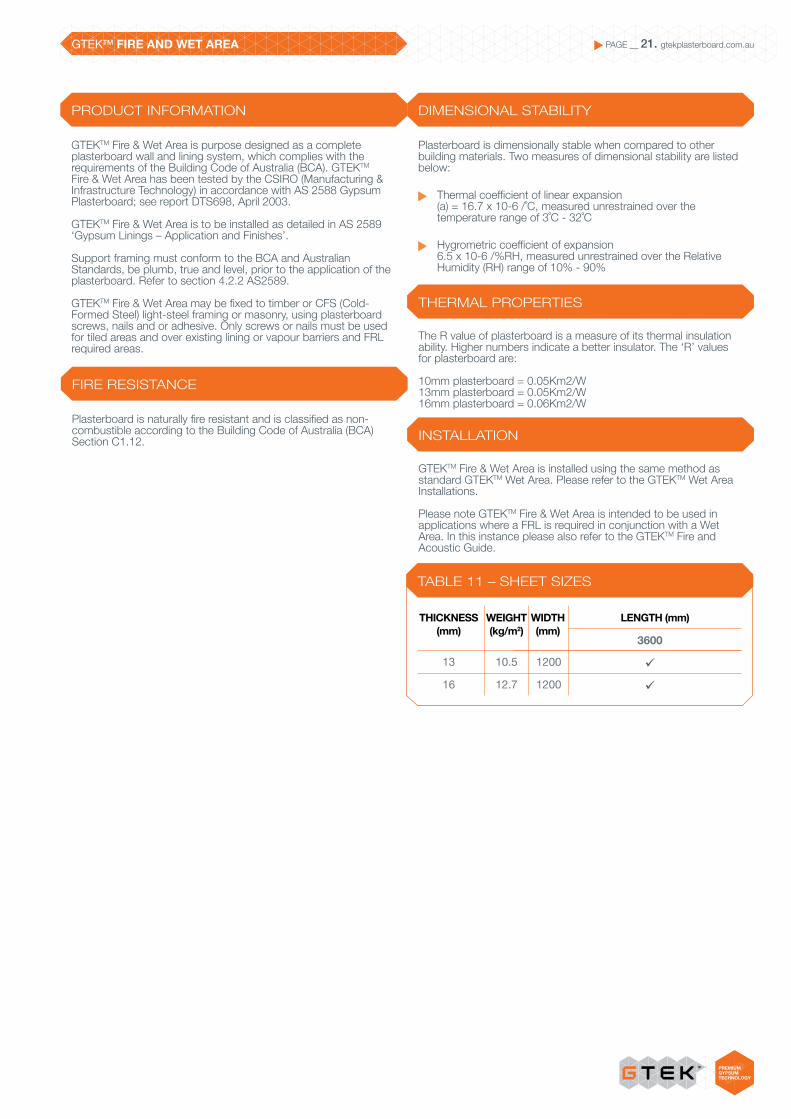
TABLE 11 – SHEET SIZES
THICKNESS (mm)
WEIGHT (kg/m2)
WIDTH (mm)
LENGTH (mm)
1200
1200
10.5
12.7
13
16
3600
ü
ü

GOOD ENVIRONMENTAL CHOICE AUSTRALIA GECA PAGE __ 22. gtekplasterboard.com.au
At BGC we care about the environment and now have a range of GECA Certified Plasterboard Products available. As part of our commitment to sustainability we are offering our Environmentally Certified GTEKTM range at no extra cost to you. So now you save money whilst together we save the environment.
BGC-2014GECA 04-2011 v2
Panel Boards

GOOD ENVIRONMENTAL CHOICE AUSTRALIA GECA PAGE __ 23. gtekplasterboard.com.au
BGC Plasterboard shares the general community concern for the environment and seeks to reduce its environmental footprint in all aspects of its operations. That means you can specify GTEKTM to help create you next green star rated home or project.We use up to 15% recycled gypsum in our boards and we use 100% recycled paper lining front and back.
BGC Plasterboard has set prudent environmental targets for waste minimisation and energy and water use, and is an active participant in environmental reporting through the Energy Efficiency, Waterwise and Emissions reporting programs.
Through strict quality control systems, production waste is minimised and wastage is recycled back into new plasterboard.
Good Environmental Choice Australia is an environmental labelling program which aims to provide consumers with the knowledge that the product they are purchasing has met certain environmental performance standards which have been developed and assessed in line with International labelling standards.
Scientifically recognised benchmarks for environmental performance have been developed against which products and services are assessed and evaluated to determine whether the product or service should be awarded the Good Environmental Choice Label. GECA certification is recognised by the Green Building Council of Australia and may assist in achieving up to 3 Green Star points.
All GTEKTM products have been certified by GECA which means that the products and their manufacturing environment have been evaluated and deemed to comply with the strict guidelines set by GECA.
We’re proud to wear the Good Environmental Choice label, it shows our products and manufacturing environment comply with GECA’s strict guidelines.
Now ‘Building it better with BGC’ also means building a cleaner and more sustainable environment.
Design by The SHAPE Group www.theshapegroup.com.au
CONTACT
TO CONTACT YOUR NEAREST BGC STOCKIST, PLEASE CALL:
ADELAIDETELEPHONE 08 8250 4962BRISBANETELEPHONE 07 3271 1711MELBOURNETELEPHONE 03 9392 9444PERTHTELEPHONE 08 9374 2900SYDNEYTELEPHONE02 9771 9660
NEW ZEALANDTELEPHONE0011 64 9273 1457
TECHNICAL HELP LINE1300 652 242
WARRANTY
We warrant that our products are free from defects caused by faulty manufacture or materials for a period of 15 years from the date of purchase. If you acquire any defective products, we will repair or replace them, supply equivalent replacement products or refund the purchase price within 30 days of receiving a valid claim subject to product inspection and confirmation of the existence of a defect by BGC. We will bear the cost of any such repair, replacement or refund.
This warranty is given by:
BGC PLASTERBOARD PTY LTDGround Floor, 290 Bushmead Rd, Hazelmere, WA 6055 Phone: (08) 9374 2900 Fax: (08) 9374 2901
To claim under this warranty, you must provide proof of purchase as a consumer and make a written claim (including any costs of claiming) to us at the address specified above within 30 days after the defect was reasonably apparent, or if the defect was reasonably apparent prior to installation, the claim must be made prior to installation. You may not claim under this warranty for loss or damage caused by:
faulty or incorrect installation by non-BGC installers (BGC’s installation procedures are at gtekplasterboard.com.au);
failure to comply with the Building Code of Australia or any applicable legislation, regulations approvals and standards;
products not made or supplied by BGC; abnormal use of the product; or normal wear and tear.
The benefits available under this warranty are in addition to other rights and remedies of the consumer under the law. Our goods come with guarantees that cannot be excluded under the Australian Consumer Law. You are entitled to a replacement or refund for a major failure and for compensation for any other reasonably foreseeable loss or damage. You are also entitled to have the goods repaired or replaced if the goods fail to be of acceptable quality and the failure does not amount to a major failure.
GTEK™ Wall is an interior wall lining system where cost effectiveness and economy of effort are crucial.
GTEK™ Curve flexible plasterboard enables the creative execution of curves on interior walls and ceilings.
GTEK™ Ceiling is a 10mm plasterboard sheet designed specifically for ceiling use where joists are at 600mm.
GTEK™ Fire is used in fire-rated systems, consisting of single or multiple layers of board.
GTEK™ Fire & Wet Area is designed for use in wet areas governed by fire resistance limitations (FRLs).
GTEK™ Wet Area is water-resistant plasterboard for walls in such wet areas as bathrooms, laundries, toilets and cleaning rooms.
GTEK™ Sound is high-density plasterboard specifically designed to reduce unwanted noise detectable through walls and ceilings.
GTEK™ Impact is ideal for high-traffic areas where walls are subjected to regular stress.
GTEK™ Total Plus offers market- leading fire, water, sound and impact resistance, together with GECA certification in recognition of high percentages of recycled materials.
GTEK™ Cornice adds exciting finishing touches to interior wall and ceiling joints in new builds and renovations.
GTEKTM PRODUCT RANGE
BGC-2014GECA 04-2011 v2
Panel Boards