Embed Size (px)
Citation preview
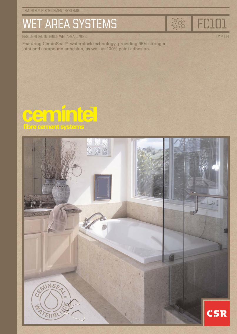
CEMINTEL™ FIBRE CEMENT SYSTEMs
wet area systemsjuly 2009
fc101residential INTERIOR wet area lining
Featuring CeminSeal™ waterblock technology, providing 95% strongerjoint and compound adhesion, as well as 100% paint adhesion.
2
CEMINTEL™ wet area systems
ADVANTAGESCeminSeal™ Wallboard Offers:• Waterblocking technology• 95% stronger joint and compound adhesion• 100% paint adhesion• Simple and quick to install• Fewer call backs, less risk
APPLICATIONSThe systems in this manual are based onAustralian Standard AS3740 ‘Waterproofing ofwet areas within residential buildings’. Thestandard details the design, materials, andinstallation requirements for wet areas withinresidential buildings.
A wet area is defined by the standard as an areawithin a building supplied with water from awater supply system, including bathrooms,showers, laundries and toilets, but excludingkitchens, bars and similar.
Each wet area is classified as having a high,medium or low level of risk. Certain walls andjunctions in each of the levels are required to bewaterproof or water resistant.
Water resistant walls are those areas enclosingand within a shower compartment, and wallsadjacent to fixed vessels such as baths, spasand tubs, i.e. part wall areas within bathrooms,ensuites and laundries.
Waterproof areas are junctions between wallsand between floors and walls in showers andbathrooms, and near baths, spas, sinks etc.
Cemintel™ Wet Area lining Systems offer proven,reliable and cost effective solutions to allresidential wet areas.
WATER RESISTANT AREAS.CeminSeal™ Wallboard is used as a substratefor ceramic tiles, and must be fastened withnails or screws only. CeminSeal™ Wallboardsheets are then jointed with CSR Gyprock™ WetArea Base Coat and tape.
GENERAL WET AREAS.CeminSeal™ Wallboard is installed into theseareas in a similar manner to that used for fixingstandard Gyprock™ plasterboard.
CeminSeal™ Wallboard sheets to be used as asubstrate for tiling, must be fixed with nails orscrews only.
CONTENTSWET AREA LINING SYSTEMS.
Description, Advantages, Applications. 2.Material Properties. 3.Components. 3.Sheet Preparation. 4.Handling, Storage & Safety. 5.Control Joints. 5.Framing. 6.CeminSeal™ Wallboard Installation. 6 – 7.General Wet Area Flashing. 8.Shower Recess Construction. 9 – 11.Bath, Shower Over Bath and Unenclosed Shower Construction. 12 – 13.Caulking & Flashing Details. 14.Jointing Systems & Decoration. 15 – 19.
WET AREA FLOORING SYSTEM.
Description & Advantages. 20.Material Properties. 20.Components. 20.Framing. 21.Sheet Preparation. 21.Installation. 21.Waterproofing. 22 – 23.Tile Laying. 23.Health & Safety. 24.
WET AREA LININGSYSTEMSDESCRIPTION.CeminSeal™ Wallboard features an embeddedmicro waterblock technology that preventswater penetrating into the sheet, repelling waterand providing a more stable sheet.
With CeminSeal™ you will achieve 95%stronger joint and compound adhesion, as wellas 100% paint adhesion.
Ideal for lining areas such as bathrooms,laundries and semi-exposed ceilings, and forconstruction of impact resistant walls.
CeminSeal™Wallboard has a recess on bothlong edges so that sheets may be taped and setwith CSR Gyprock and Cemintel™Jointingmaterials. Once jointed it may be tiled paintedor wall papered as desired.
CeminSeal™ Wallboard means less risk. A costeffective solution, giving you and yourcustomers greater long-term security.

3
CEMINTEL™ wet area systems
Width mm.Length mm.
180024002700300036004200
900
✓
1200✓
✓ ■
✓ ■
✓ ■ ✤
✓
✓
1350
✓
✓
✓
✓
Thickness(6mm RE = ✓) (9mm RE = ■) (12mm RE = ✤)
FASTENERS.To guarantee performance, only approvedfasteners should be used in these systems.
CeminSeal™ Wallboard Nails: Hot-dipgalvanised for softwood and hardwood framing.
• For 6mm sheet – 2.8mm x 30mm.• For 9mm sheet – 2.8mm x 40mm.• For 12mm sheet – 2.8mm x 40mm.
COMPONENTSCEMINSEAL™ WALLBOARD.CeminSeal™ Wallboard is manufactured in thefollowing sizes, with the two long edgesrecessed to allow seamless jointing.
STUD ADHESIVE (FOR NON TILED AREAS ONLY).• Gyprock™ Acrylic Stud Adhesive.
JOINTING MATERIALS.
• CSR Gyprock™ Wet Area Base Coat.
• Gyprock™ Paper Joint Reinforcing Tape.
• Gyprock Easytape™.
• Gyprock™ finishing compounds (non tiled areasonly).
VERTICAL CORNER FLASHING.• External Vertical Flashing Angle:
Cemintel™ PVC angle 50 x 50mm. For usewith external and preformed shower trays.
• Internal Vertical Flashing*: A liquidapplied membrane such as ABA Superflex™ I,with a bond breaker. For use with internalshower trays.
PERIMETER FLASHING.
• Perimeter Flashing Angle: Cemintel™ PVCangle 75 x 50mm.
• Perimeter Flashing for Step-Down Slab*:Such as Sikadur™ Combiflex 150mm.
• Proprietary Insitu Membranes: Such asABA Superflex™ I with bond breaker.
• Adhesive Fulaprene 303*: For fixing angleto slab, timber or fibre cement flooring.
FLEXIBLE SEALANT*.• Fullers Brick & Concrete Sealant: To fibre
cement
NOTE: Only use sealants suitable for cementand concrete substrates.
*Supplied by others.• Gyprock™ Wet Area Acrylic Sealant:Painted and tiled areas.
FIRE RESISTANCE.
Under the Building Code of Australia, C1.1Clause 2.5(e), Cemintel™ Fibre Cement isdeemed to be non-combustible.
The Fire Hazard Properties, when tested inaccordance with AS1530.3 are as follows:
FIRE HAZARD INDICES.
Ignitability 0
Spread of Flame 0
Heat Evolved 0
Smoke Developed 0
MATERIALPROPERTIESCeminSeal™ Wallboard Sheet conforms to therequirements of AS2908.2 : 1992 ‘Cellulose-cement products Part 2: Flat sheets’. Type A,Category 3.
PROPERTIES
Mass 6mm thickness (nominal) 9.7kg/m2
Mass 9mm thickness (nominal) 14.3kg/m2
Mass 12mm thickness (nominal) 18.8kg/m2
Length +0 to -4mm
Width +0 to -3mm
Thickness +0.5 to -0mm
Diagonals Difference (max) 3mm
Screws for fixing CeminSeal™ Wallboardto Steel Framing
• Buildex FibreZIPS™, Class 3 finish, 9-18 x 30mm.
• Buildex FibreZIPS™, Class 3 finish, 9-18 x 20mm.
4
CEMINTEL™ wet area systems
Score along straight edgethen lift sheet upwards to form clean break
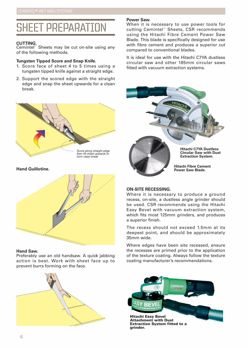
Hand Guillotine.
Hand Saw. Preferably use an old handsaw. A quick jabbingaction is best. Work with sheet face up toprevent burrs forming on the face.
SHEET PREPARATIONCUTTING.Cemintel™ Sheets may be cut on-site using anyof the following methods.
Tungsten Tipped Score and Snap Knife.
1. Score face of sheet 4 to 5 times using atungsten tipped knife against a straight edge.
2. Support the scored edge with the straightedge and snap the sheet upwards for a cleanbreak.
ON-SITE RECESSING.
Where it is necessary to produce a groundrecess, on-site, a dustless angle grinder shouldbe used. CSR recommends using the HitachiEasy Bevel with vacuum extraction system,which fits most 125mm grinders, and producesa superior finish.
The recess should not exceed 1.5mm at itsdeepest point, and should be approximately35mm wide.
Where edges have been site recessed, ensurethe recesses are primed prior to the applicationof the texture coating. Always follow the texturecoating manufacturer’s recommendations.
Power Saw.When it is necessary to use power tools forcutting Cemintel™ Sheets, CSR recommendsusing the Hitachi Fibre Cement Power SawBlade. This blade is specifically designed for usewith fibre cement and produces a superior cutcompared to conventional blades.
It is ideal for use with the Hitachi C7YA dustlesscircular saw and other 185mm circular sawsfitted with vacuum extraction systems.
Hitachi C7YA DustlessCircular Saw with DustExtraction System.
Hitachi Fibre CementPower Saw Blade.
Hitachi Easy BevelAttachment with DustExtraction System fitted to agrinder.
5
CEMINTEL™ wet area systems
HANDLING ANDSTORAGEAll Cemintel™ sheeting must be stacked flat, offthe ground, and supported on a level platform.Care must be taken to avoid damage to edges,ends and surfaces. Material must be kept dry,preferably by being stored inside the building.Where it is necessary to store sheets outside,they must be protected from the weather.Sheets must be dry prior to fixing, jointing andfinishing.
SAFETYWhen cutting or grinding fibre cement sheetsusing power tools, always ensure the work areais well ventilated. An approved dust mask(AS1715 and AS1716) and safety glasses(AS1337) must be worn. CSR recommends thathearing protection be worn where appropriate.
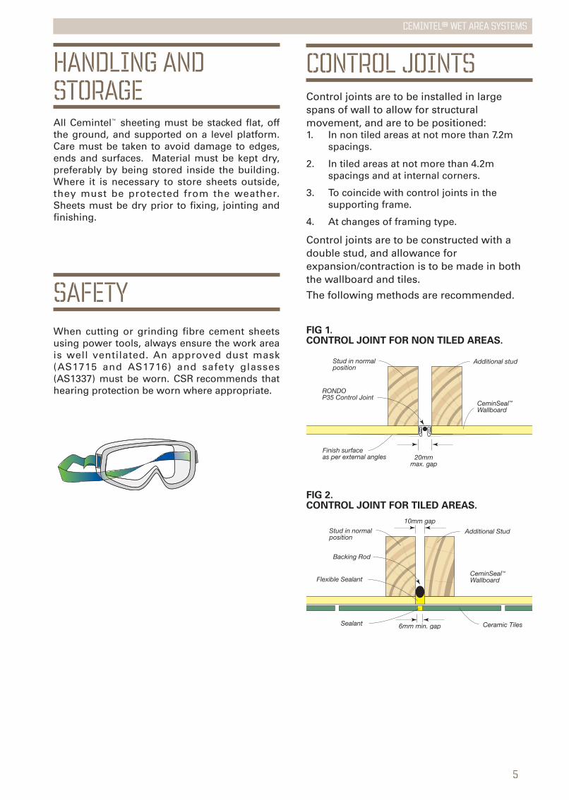
CONTROL JOINTSControl joints are to be installed in largespans of wall to allow for structuralmovement, and are to be positioned:1. In non tiled areas at not more than 7.2m
spacings.
2. In tiled areas at not more than 4.2m spacings and at internal corners.
3. To coincide with control joints in the supporting frame.
4. At changes of framing type.
Control joints are to be constructed with adouble stud, and allowance forexpansion/contraction is to be made in boththe wallboard and tiles.
The following methods are recommended.
CeminSeal™Wallboard
20mmmax. gap
RONDOP35 Control Joint
Stud in normal position
Additional stud
Finish surface as per external angles
CeminSeal™Wallboard
6mm min. gap
10mm gap
Backing Rod
Stud in normal position
Additional Stud
Ceramic Tiles
Flexible Sealant
Sealant
FIG 1. CONTROL JOINT FOR NON TILED AREAS.
FIG 2. CONTROL JOINT FOR TILED AREAS.
6
CEMINTEL™ wet area systems
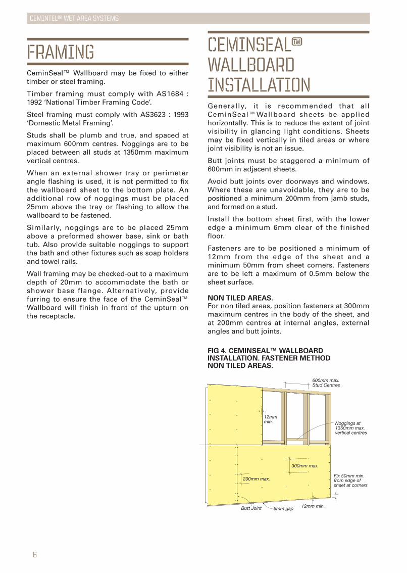
200mm max.
300mm max.
6mm gap 12mm min.
12mm min.
Fix 50mm min. from edge of sheet at corners
600mm max. Stud Centres
Butt Joint
Noggings at 1350mm max. vertical centres
CEMINSEAL™WALLBOARDINSTALLATIONGenerally, it is recommended that allCeminSeal™Wallboard sheets be appliedhorizontally. This is to reduce the extent of jointvisibility in glancing light conditions. Sheetsmay be fixed vertically in tiled areas or wherejoint visibility is not an issue.
Butt joints must be staggered a minimum of600mm in adjacent sheets.
Avoid butt joints over doorways and windows.Where these are unavoidable, they are to bepositioned a minimum 200mm from jamb studs,and formed on a stud.
Install the bottom sheet first, with the loweredge a minimum 6mm clear of the finishedfloor.
Fasteners are to be positioned a minimum of12mm from the edge of the sheet and aminimum 50mm from sheet corners. Fastenersare to be left a maximum of 0.5mm below thesheet surface.
NON TILED AREAS.For non tiled areas, position fasteners at 300mmmaximum centres in the body of the sheet, andat 200mm centres at internal angles, externalangles and butt joints.
FIG 4. CEMINSEAL™ WALLBOARDINSTALLATION. FASTENER METHOD NON TILED AREAS.
FRAMINGCeminSeal™ Wallboard may be fixed to eithertimber or steel framing.
Timber framing must comply with AS1684 :1992 ‘National Timber Framing Code’.
Steel framing must comply with AS3623 : 1993‘Domestic Metal Framing’.
Studs shall be plumb and true, and spaced atmaximum 600mm centres. Noggings are to beplaced between all studs at 1350mm maximumvertical centres.
When an external shower tray or perimeterangle flashing is used, it is not permitted to fixthe wallboard sheet to the bottom plate. Anadditional row of noggings must be placed25mm above the tray or flashing to allow thewallboard to be fastened.
Similarly, noggings are to be placed 25mmabove a preformed shower base, sink or bathtub. Also provide suitable noggings to supportthe bath and other fixtures such as soap holdersand towel rails.
Wall framing may be checked-out to a maximumdepth of 20mm to accommodate the bath orshower base flange. Alternatively, providefurring to ensure the face of the CeminSeal™Wallboard will finish in front of the upturn onthe receptacle.
7
CEMINTEL™ wet area systems
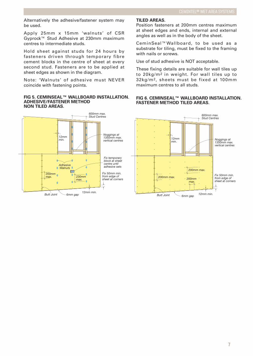
TILED AREAS.Position fasteners at 200mm centres maximumat sheet edges and ends, internal and externalangles as well as in the body of the sheet.
CeminSeal™Wallboard, to be used as asubstrate for tiling, must be fixed to the framingwith nails or screws.
Use of stud adhesive is NOT acceptable.
These fixing details are suitable for wall tiles upto 20kg/m2 in weight. For wall tiles up to32kg/m2, sheets must be fixed at 100mmmaximum centres to all studs.
200mm max. 200mm max.
200mm max.
6mm gap12mm min.
12mm min.
Fix 50mm min. from edge of sheet at corners
600mm max. Stud Centres
Butt Joint
Noggings at 1350mm max. vertical centres
FIG 6. CEMINSEAL™ WALLBOARD INSTALLATION.FASTENER METHOD TILED AREAS.
200mm max. 230mm
max.
6mm gap12mm min.
12mm min.
Fix 50mm min. from edge of sheet at corners
600mm max. Stud Centres
AdhesiveWalnuts
Fix temporary block at sheetcentre untiladhesive sets
Butt Joint
Noggings at 1350mm max. vertical centres
FIG 5. CEMINSEAL™ WALLBOARD INSTALLATION.ADHESIVE/FASTENER METHOD NON TILED AREAS.
Alternatively the adhesive/fastener system maybe used.
Apply 25mm x 15mm ‘walnuts’ of CSRGyprock™ Stud Adhesive at 230mm maximumcentres to intermediate studs.
Hold sheet against studs for 24 hours byfasteners driven through temporary fibrecement blocks in the centre of sheet at everysecond stud. Fasteners are to be applied atsheet edges as shown in the diagram.
Note: ‘Walnuts’ of adhesive must NEVERcoincide with fastening points.
8
CEMINTEL™ wet area systems
CeminSeal™Wallboard
Ceramic Tiles
Approved Flashing
Ceramic Tiles
6mm
Flexible Sealant
Mortar bed
25mmmin.
Stepped concreteslab or hob cast integrally with slab
FIG 8. PERIMETER FLASHING.FOR STEP-DOWN SLAB IN GENERAL WET AREA.
CeminSeal™Wallboard
Ceramic Tiles
Wall Plate
Structural Sheet Flooring
Stud
Flexible Sealant
Nogging for wallboard fixing
Floor Joist
Approved Flashing adhesive fixed to floor only
50mmmin.
75mmmin.
25mm min.
Cemintel™Compressed Sheet flooring
Mortar Bed
FIG 7. PERIMETER FLASHING.PVC ANGLE IN GENERAL WET AREA.
FIG 9. PERIMETER FLASHING. INSITU MEMBRANE IN GENERAL WET AREA.
CeminSeal™Wallboard
Ceramic Tiles
Wall Plate
Structural Sheet Flooring
Masking Tape
Flexible Sealant
Stud
Floor Joist
Membranefinishedminimum25mm above highest point of finishedfloor surface
Minimum 50mm
Foam Plastic Rod used as essential bond breaker
Mortar Bed
Insitu Membrane applied to face of wall lining and floor
Cemintel™ Compressed Sheet flooring
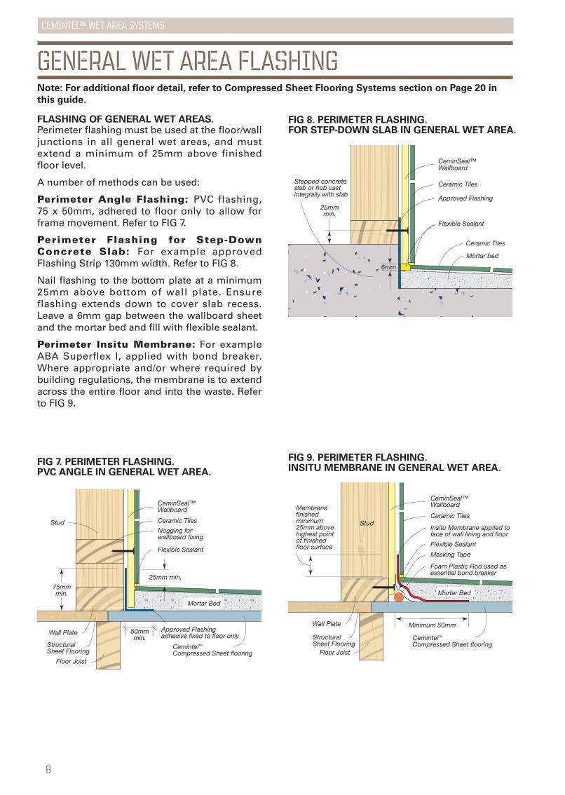
FLASHING OF GENERAL WET AREAS.Perimeter flashing must be used at the floor/walljunctions in all general wet areas, and mustextend a minimum of 25mm above finishedfloor level.
A number of methods can be used:
Perimeter Angle Flashing: PVC flashing,75 x 50mm, adhered to floor only to allow forframe movement. Refer to FIG 7.
Perimeter Flashing for Step-DownConcrete Slab: For example approvedFlashing Strip 130mm width. Refer to FIG 8.
Nail flashing to the bottom plate at a minimum25mm above bottom of wall plate. Ensureflashing extends down to cover slab recess.Leave a 6mm gap between the wallboard sheetand the mortar bed and fill with flexible sealant.
Perimeter Insitu Membrane: For exampleABA Superflex I, applied with bond breaker.Where appropriate and/or where required bybuilding regulations, the membrane is to extendacross the entire floor and into the waste. Referto FIG 9.
GENERAL WET AREA FLASHINGNote: For additional floor detail, refer to Compressed Sheet Flooring Systems section on Page 20 in
this guide.
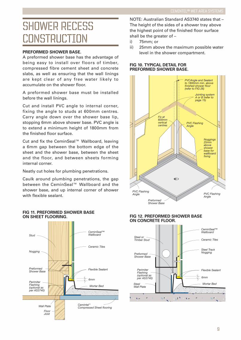
FIG 10. TYPICAL DETAIL FORPREFORMED SHOWER BASE.
FIG 12. PREFORMED SHOWER BASEON CONCRETE FLOOR.
Preformed Shower Base
Noggings 25mm above shower base for wallboard fixing
PVC Flashing Angle PVC Flashing
Angle
PVC Flashing Angle
Fix at 600mm vertical centres
Jointing system A or B (refer to page 15)
PVCAngle and Sealant to 1800mm min. above finished shower floor (refer to FIG 26)
Structural
CeminSeal™Wallboard
Ceramic Tiles
Mortar Bed
6mm
Steel TrackNogging
Flexible Sealant
Steel orTimber Stud
PreformedShower Base
SteelWall Plate
Perimiter Flashing (optional as per AS3740)
NOTE: Australian Standard AS3740 states that –The height of the sides of a shower tray abovethe highest point of the finished floor surfaceshall be the greater of –i) 75mm; orii) 25mm above the maximum possible water
level in the shower compartment.
SHOWER RECESSCONSTRUCTIONPREFORMED SHOWER BASE.
A preformed shower base has the advantage ofbeing easy to install over floors of timber,compressed fibre cement sheet and concreteslabs, as well as ensuring that the wall liningsare kept clear of any free water likely toaccumulate on the shower floor.
A preformed shower base must be installedbefore the wall linings.
Cut and install PVC angle to internal corner,fixing the angle to studs at 600mm centres.Carry angle down over the shower base lip,stopping 6mm above shower base. PVC angle isto extend a minimum height of 1800mm fromthe finished floor surface.
Cut and fix the CeminSeal™ Wallboard, leavinga 6mm gap between the bottom edge of thesheet and the shower base, between the sheetand the floor, and between sheets forminginternal corner.
Neatly cut holes for plumbing penetrations.
Caulk around plumbing penetrations, the gapbetween the CeminSeal™ Wallboard and theshower base, and up internal corner of showerwith flexible sealant.
Perimiter Flashing (optional as per AS3740)
Mortar Bed
6mm
PreformedShower Base
Nogging
StudCeminSeal™Wallboard
Ceramic Tiles
Flexible Sealant
Wall Plate
Floor Joist
Cemintel™Compressed Sheet flooring
FIG 11. PREFORMED SHOWER BASEON SHEET FLOORING.
9
CEMINTEL™ wet area systems
10
CEMINTEL™ wet area systems
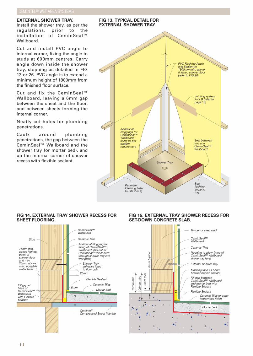
EXTERNAL SHOWER TRAY.Install the shower tray, as per theregulations, prior to theinstallation of CeminSeal™Wallboard.
Cut and install PVC angle tointernal corner, fixing the angle tostuds at 600mm centres. Carryangle down inside the showertray, stopping as detailed in FIG13 or 26. PVC angle is to extend aminimum height of 1800mm fromthe finished floor surface.
Cut and fix the CeminSeal™Wallboard, leaving a 6mm gapbetween the sheet and the floor,and between sheets forming theinternal corner.
Neatly cut holes for plumbingpenetrations.
Caulk around plumbingpenetrations, the gap between theCeminSeal™ Wallboard and theshower tray (or mortar bed), andup the internal corner of showerrecess with flexible sealant.
Cemintel™ Compressed Sheet flooring
CeminSeal™Wallboard
Ceramic Tiles
Ceramic Tiles6mm
Flexible Sealant
Mortar bed
25mm
Stud
75mm min. above highest point of shower floor and min. 25mm above max. possible water level
Shower Tray adhesive fixed to floor only
Additional Nogging for fixing of CeminSeal™ Wallboard. (Do not fix CeminSeal™ Wallboard through shower tray into wall plate)
Fill gap at base of CeminSeal™Wallboard with Flexible Sealant
FIG 14. EXTERNAL TRAY SHOWER RECESS FORSHEET FLOORING.
CeminSeal™Wallboard
Timber or steel stud
Ceramic Tiles
Ceramic Tiles or otherimpervious finish
Mortar bed
6mm
min
.
100m
m m
in.
75m
m m
in.
Masking tape as bond breaker behind sealant
Fill gap between CeminSeal™ Wallboard and mortar bed with Flexible Sealant
External Shower Tray
Nogging to allow fixing of CeminSeal™ Wallboard above tray level
Flexible Sealant
6mm
typ
ical
FIG 15. EXTERNAL TRAY SHOWER RECESS FORSET-DOWN CONCRETE SLAB.
Perimeter Flashing (refer to FIG 7 or 9)
Seal flashing angle to tray
Shower Tray
Additional Noggings for CeminSeal™Wallboard fixing as per system requirement
PVC Flashing Angle and Sealant to 1800mm min. above finished shower floor (refer to FIG 26)
Jointing system A or B (refer to page 15)
Seal betweentray and CeminSeal™Wallboard
FIG 13. TYPICAL DETAIL FOREXTERNAL SHOWER TRAY.
11
CEMINTEL™ wet area systems
15mm min. to finished shower floor level
Timber or Steel stud
CeminSeal™Wallboard
Ceramic Tiles
Masking Tape
Flexible Sealant
Foam Plastic Rodused as essentialbond breaker
Insitu Internal Trayapplied to face of wall lining and floor
50mmmin.
Mortar Bed
75mm min. above highest point of shower floor and min. 25mm above max. possible water level
Perimeter flashing (optional as per AS3740)
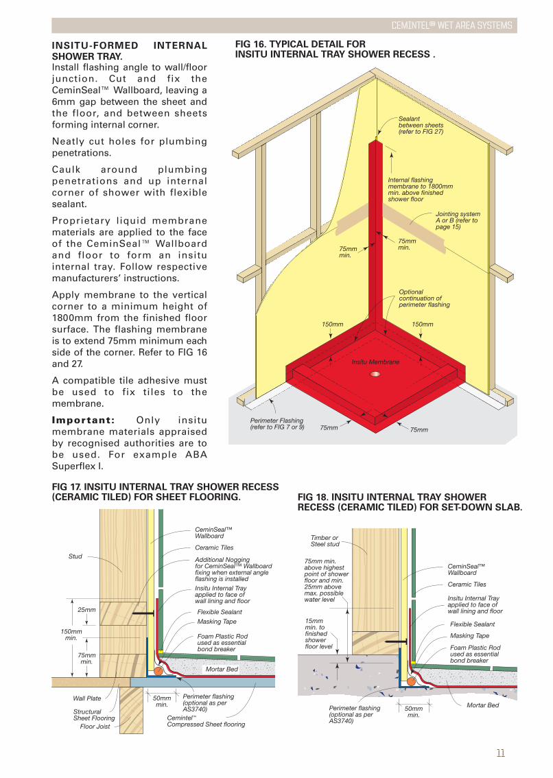
FIG 18. INSITU INTERNAL TRAY SHOWERRECESS (CERAMIC TILED) FOR SET-DOWN SLAB.
Flexible Sealant
Foam Plastic Rodused as essentialbond breaker
CeminSeal™Wallboard
Ceramic Tiles
Masking Tape
Insitu Internal Trayapplied to face of wall lining and floor
Additional Noggingfor CeminSeal™ Wallboardfixing when external angle flashing is installed
Wall Plate
Structural Sheet Flooring
Stud
Floor Joist
75mmmin.
25mm
150mmmin.
Perimeter flashing (optional as per AS3740)
50mmmin.
Cemintel™ Compressed Sheet flooring
Mortar Bed
INSITU-FORMED INTERNALSHOWER TRAY.Install flashing angle to wall/floorjunction. Cut and fix theCeminSeal™ Wallboard, leaving a6mm gap between the sheet andthe floor, and between sheetsforming internal corner.
Neatly cut holes for plumbingpenetrations.
Caulk around plumbingpenetrations and up internalcorner of shower with flexiblesealant.
Proprietary liquid membranematerials are applied to the faceof the CeminSeal™ Wallboardand floor to form an insituinternal tray. Follow respectivemanufacturers’ instructions.
Apply membrane to the verticalcorner to a minimum height of1800mm from the finished floorsurface. The flashing membraneis to extend 75mm minimum eachside of the corner. Refer to FIG 16and 27.
A compatible tile adhesive mustbe used to fix tiles to themembrane.
Important: Only insitumembrane materials appraisedby recognised authorities are tobe used. For example ABASuperflex I.
FIG 17. INSITU INTERNAL TRAY SHOWER RECESS(CERAMIC TILED) FOR SHEET FLOORING.
75mmmin.
75mm
75mmmin.
75mm
150mm 150mm
Perimeter Flashing (refer to FIG 7 or 9)
Internal flashing membrane to 1800mm min. above finished shower floor
Optional continuation of perimeter flashing
Jointing system A or B (refer to page 15)
Sealant between sheets (refer to FIG 27)
Insitu Membrane
FIG 16. TYPICAL DETAIL FORINSITU INTERNAL TRAY SHOWER RECESS .
12
CEMINTEL™ wet area systems
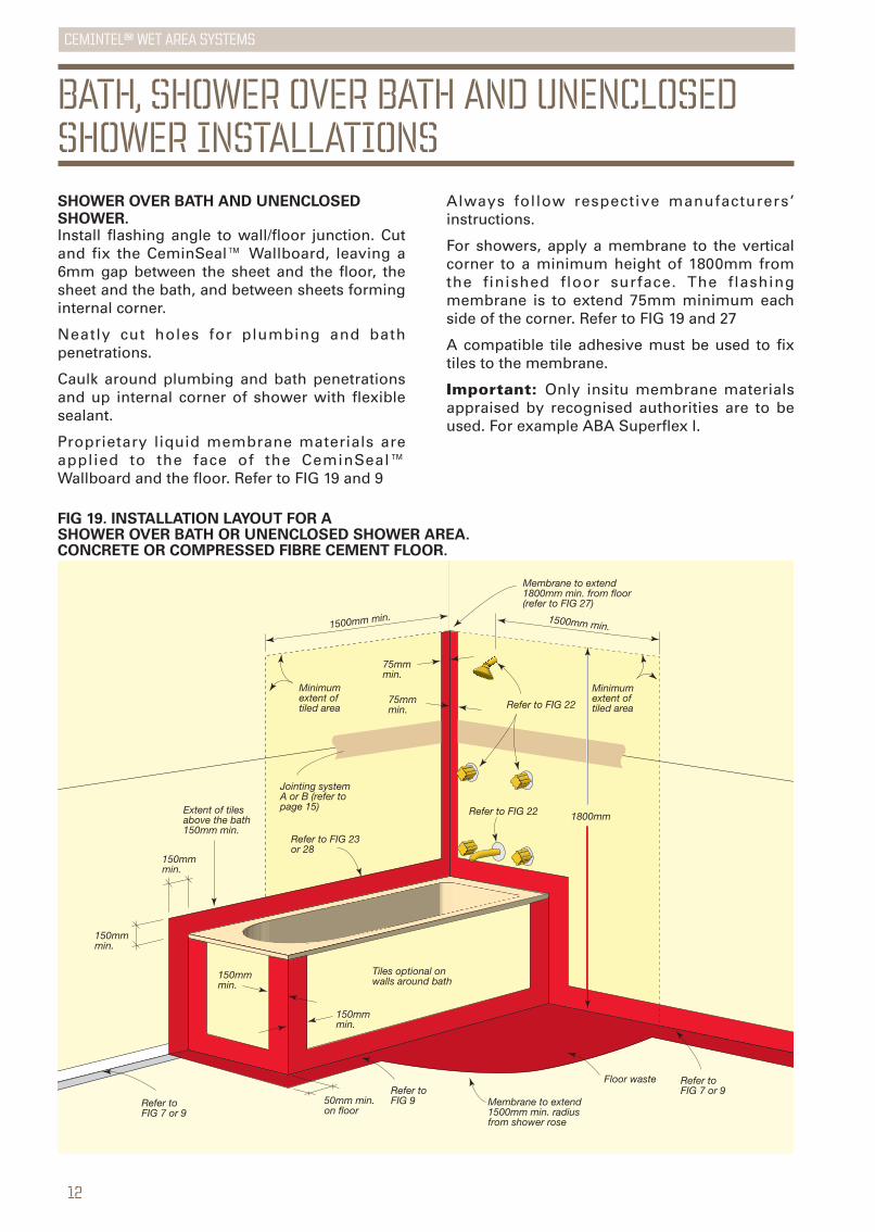
FIG 19. INSTALLATION LAYOUT FOR ASHOWER OVER BATH OR UNENCLOSED SHOWER AREA.CONCRETE OR COMPRESSED FIBRE CEMENT FLOOR.
SHOWER OVER BATH AND UNENCLOSEDSHOWER.Install flashing angle to wall/floor junction. Cutand fix the CeminSeal™ Wallboard, leaving a6mm gap between the sheet and the floor, thesheet and the bath, and between sheets forminginternal corner.
Neatly cut holes for plumbing and bathpenetrations.
Caulk around plumbing and bath penetrationsand up internal corner of shower with flexiblesealant.
Proprietary liquid membrane materials areapplied to the face of the CeminSeal™Wallboard and the floor. Refer to FIG 19 and 9
Always follow respective manufacturers’instructions.
For showers, apply a membrane to the verticalcorner to a minimum height of 1800mm fromthe finished floor surface. The flashingmembrane is to extend 75mm minimum eachside of the corner. Refer to FIG 19 and 27
A compatible tile adhesive must be used to fixtiles to the membrane.
Important: Only insitu membrane materialsappraised by recognised authorities are to beused. For example ABA Superflex I.
BATH, SHOWER OVER BATH AND UNENCLOSEDSHOWER INSTALLATIONS
1500mm min. 1500mm min.
Minimum extent of tiled area
Minimum extent of tiled area
Tiles optional on walls around bath
50mm min. on floor
Membrane to extend 1500mm min. radius from shower rose
Membrane to extend 1800mm min. from floor (refer to FIG 27)
Jointing systemA or B (refer to page 15)
Refer to FIG 23 or 28
Refer to FIG 22
Refer to FIG 22
Refer to FIG 7 or 9
Refer to FIG 7 or 9Refer to
FIG 9
1800mm
75mmmin.
75mmmin.
150mm min.
150mmmin.
150mmmin.
150mmmin.
Extent of tiles above the bath 150mm min.
Floor waste
13
CEMINTEL™ wet area systems
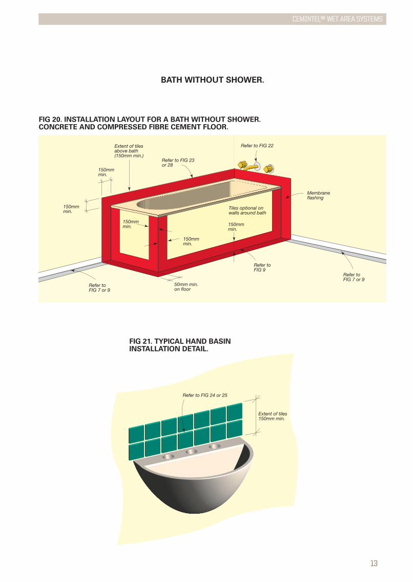
FIG 20. INSTALLATION LAYOUT FOR A BATH WITHOUT SHOWER.CONCRETE AND COMPRESSED FIBRE CEMENT FLOOR.
BATH WITHOUT SHOWER.
Extent of tiles150mm min.
Refer to FIG 24 or 25
FIG 21. TYPICAL HAND BASIN INSTALLATION DETAIL.
Tiles optional on walls around bath
Refer to FIG 23 or 28
Refer to FIG 22
50mm min. on floor
Refer to FIG 7 or 9
Refer to FIG 7 or 9
Refer to FIG 9
Membraneflashing
150mm min.
150mm min.
150mm min.
150mm min.
150mm min.
Extent of tiles above bath (150mm min.)
14
CEMINTEL™ wet area systems
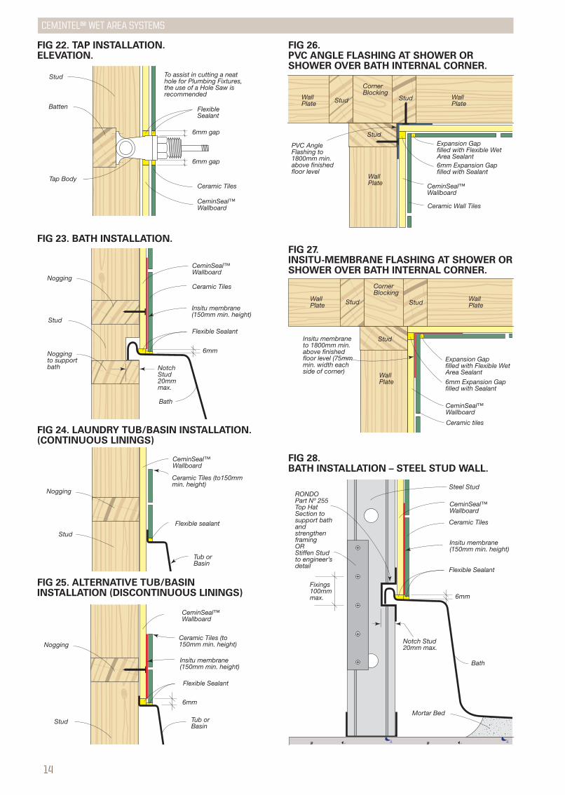
FIG 28. BATH INSTALLATION – STEEL STUD WALL.
Ceramic Tiles
6mm
Flexible Sealant
Steel Stud
Bath
CeminSeal™ Wallboard
RONDOPart Nº 255 Top Hat Section to support bath and strengthen framing OR Stiffen Stud to engineer’s detail
Fixings100mmmax.
Notch Stud20mm max.
Insitu membrane (150mm min. height)
Mortar Bed
CeminSeal™ Wallboard
Ceramic TilesTap Body
Batten
Stud
FlexibleSealant
To assist in cutting a neat hole for Plumbing Fixtures, the use of a Hole Saw is recommended
6mm gap
6mm gap
CeminSeal™Wallboard
Ceramic Tiles
6mm
Nogging
Noggingto supportbath
Flexible Sealant
Stud
Bath
Notch Stud20mm max.
Insitu membrane (150mm min. height)
Ceramic Tiles (to150mm min. height)
Flexible sealant
Nogging
Stud
Tub orBasin
CeminSeal™Wallboard
FIG 22. TAP INSTALLATION.ELEVATION.
FIG 23. BATH INSTALLATION.
FIG 24. LAUNDRY TUB/BASIN INSTALLATION.(CONTINUOUS LININGS)
FIG 25. ALTERNATIVE TUB/BASININSTALLATION (DISCONTINUOUS LININGS)
Ceramic Tiles (to 150mm min. height)
CeminSeal™ Wallboard
Nogging
6mm
Flexible Sealant
Tub orBasin
Stud
Insitu membrane (150mm min. height)
Ceramic Wall Tiles
Stud Stud
Stud
CeminSeal™ Wallboard
Expansion Gapfilled with Flexible Wet Area Sealant6mm Expansion Gapfilled with Sealant
Corner Blocking
WallPlate
WallPlate
WallPlate
PVC Angle Flashing to 1800mm min. above finished floor level
FIG 26. PVC ANGLE FLASHING AT SHOWER OR SHOWER OVER BATH INTERNAL CORNER.
Ceramic tiles
Stud
Stud Stud
CeminSeal™ Wallboard
Expansion Gapfilled with Flexible Wet Area Sealant
6mm Expansion Gapfilled with Sealant
Corner Blocking
WallPlate
WallPlate
WallPlate
Insitu membrane to 1800mm min. above finished floor level (75mm min. width each side of corner)
FIG 27.INSITU-MEMBRANE FLASHING AT SHOWER ORSHOWER OVER BATH INTERNAL CORNER.
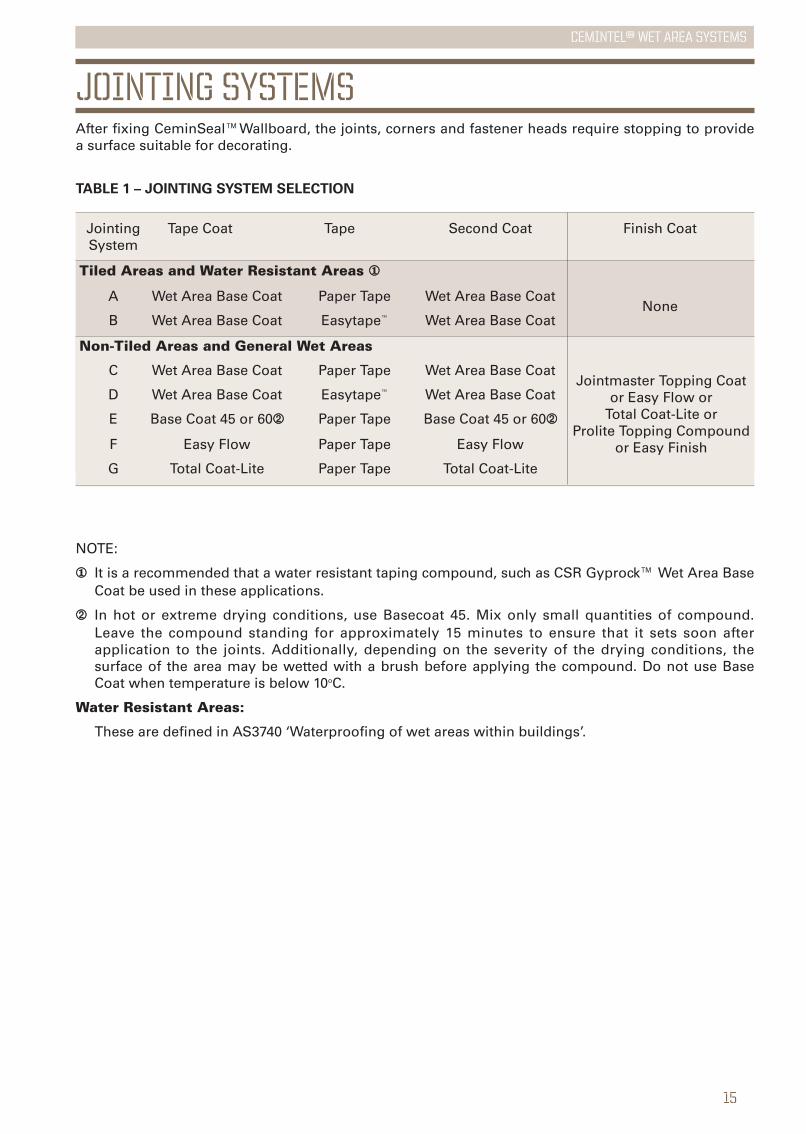
JOINTING SYSTEMSAfter fixing CeminSeal™Wallboard, the joints, corners and fastener heads require stopping to providea surface suitable for decorating.
NOTE:
①① It is a recommended that a water resistant taping compound, such as CSR Gyprock™ Wet Area BaseCoat be used in these applications.
➁➁ In hot or extreme drying conditions, use Basecoat 45. Mix only small quantities of compound.Leave the compound standing for approximately 15 minutes to ensure that it sets soon afterapplication to the joints. Additionally, depending on the severity of the drying conditions, thesurface of the area may be wetted with a brush before applying the compound. Do not use BaseCoat when temperature is below 10oC.
Water Resistant Areas:
These are defined in AS3740 ‘Waterproofing of wet areas within buildings’.
Jointing Tape Coat Tape Second Coat Finish CoatSystem
Tiled Areas and Water Resistant Areas ①①
A Wet Area Base Coat Paper Tape Wet Area Base CoatNone
B Wet Area Base Coat Easytape™ Wet Area Base Coat
Non-Tiled Areas and General Wet Areas
C Wet Area Base Coat Paper Tape Wet Area Base Coat
D Wet Area Base Coat Easytape™ Wet Area Base Coat
E Base Coat 45 or 60➁➁ Paper Tape Base Coat 45 or 60➁➁
F Easy Flow Paper Tape Easy Flow
G Total Coat-Lite Paper Tape Total Coat-Lite
Jointmaster Topping Coator Easy Flow or
Total Coat-Lite orProlite Topping Compound
or Easy Finish
TABLE 1 – JOINTING SYSTEM SELECTION
15
CEMINTEL™ wet area systems

16
CEMINTEL™ wet area systems
JOINTING COMPOUNDS.
GYPROCK jointing compounds are classified aseither setting type, drying type or acrylic dryingtype. All compounds can be applied by hand orwith mechanical jointing tools.
Setting type compounds produce stronger jointsand reduce installation delays and shrinkageassociated with drying-type compounds. Theyare recommended for experienced tradespeople and have a defined setting time e.g. 45or 60 minutes.
Setting type compounds are: BASE COAT 45,BASE COAT 60, BASE COAT 90.
Additional coats may be applied over settingtype compounds once they have gone hard(set), usually 40 minutes to an hour. A dryingtype compound must be used as a finish coatand must be completely dry before sanding.This may take up to 24 hours.
Drying type compounds are: JOINTMASTERTOPPING, TOTAL COAT-LITE, TAPE andTOPPING, EASY FINISH, and PRO-LITETOPPING. These products are premixed andTOTAL COAT-LITE is also available dry.
Acrylic drying type compounds are: WETAREA BASE COAT. This compound, when usedin conjunction with Paper Tape or Easytape™,produces very strong and durable joints. Thesejoints are resistant to a some movement withoutdisplaying cracking.
Drying type compounds will shrink and hardenwith evaporation of their water content. Thejoints must be allowed to set and appearcompletely dry before re-coating or sanding.Actual drying times will be extended in lowtemperature and high humidity conditions. Donot use a setting type compound over adrying type compound.
JOINTING TAPE.
Gyprock™ Perforated Paper Tape has beendeveloped to enable the preparation of strongjoints and should be used on butt and recessjoints as detailed in Tables 1.
Gyprock Easytape™ is ideal for use with WetArea Base Coat, provided it is bedded intothe compound. Sticking Easytape™ to the fibrecement sheet is not recommended, and couldresult in cracking.
17
CEMINTEL™ wet area systems
180m
m27
0mm
Tape Coat
Second Coat
Finish Coat
100mm
RecessedSheetEdge
CeminSeal™Wallboard
Tape bedded in tape coat
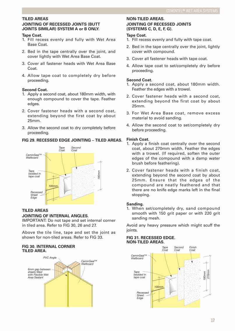
FIG 31. RECESSED EDGE.NON-TILED AREAS.
TILED AREAS
JOINTING OF RECESSED JOINTS (BUTTJOINTS SIMILAR) SYSTEM A or B ONLY.
Tape Coat.1. Fill recess evenly and fully with Wet Area
Base Coat.
2. Bed in the tape centrally over the joint, andcover lightly with Wet Area Base Coat.
3. Cover all fastener heads with Wet Area BaseCoat.
4. Allow tape coat to completely dry beforeproceeding.
Second Coat.1. Apply a second coat, about 180mm width, with
enough compound to cover the tape. Featheredges.
2. Cover fastener heads with a second coat,extending beyond the first coat by about25mm.
3. Allow the second coat to dry completely beforeproceeding.
180m
m
Tape Coat
Second Coat
100mm
CeminSeal™Wallboard
Tape bedded in tape coat
RecessedSheetEdge
FIG 29. RECESSED EDGE JOINTING – TILED AREAS.
NON-TILED AREAS.
JOINTING OF RECESSED JOINTS(SYSTEMS C, D, E, F, G).
Tape Coat.1. Fill recess evenly and fully with tape coat.
2. Bed in the tape centrally over the joint, lightlycover with compound.
3. Cover all fastener heads with tape coat.
4. Allow tape coat to set/completely dry beforeproceeding.
Second Coat.1. Apply a second coat, about 180mm width.
Feather the edges with a trowel.
2. Cover fastener heads with a second coat,extending beyond the first coat by about25mm.
3. For Wet Area Base coat, remove excessmaterial to avoid sanding.
4. Allow the second coat to set/completely drybefore proceeding.
Finish Coat.1. Apply a finish coat centrally over the second
coat, about 270mm width. Feather the edgeswith a trowel. (If required, soften the outeredges of the compound with a damp waterbrush before feathering).
2. Cover fastener heads with a finish coat,extending beyond the second coat by about25mm. Ensure that the edges of thecompound are neatly feathered and thatthere are no knife edge marks left in the finalstopping.
Sanding.1. When set/completely dry, sand compound
smooth with 150 grit paper or with 220 gritsanding mesh.
Avoid any heavy pressure which might scuff thejoints.
TILED AREAS
JOINTING OF INTERNAL ANGLES.IMPORTANT: Do not tape and set internal cornerin tiled area. Refer to FIG 30, 26 and 27.
Above the tile line, tape and set the joint asshown for non-tiled areas. Refer to FIG 33.
PVC Angle
6mm gap betweensheets filled with Flexible Wet Area Sealant
CeminSeal™Wallboard
FIG 30. INTERNAL CORNER TILED AREA.
18
CEMINTEL™ wet area systems
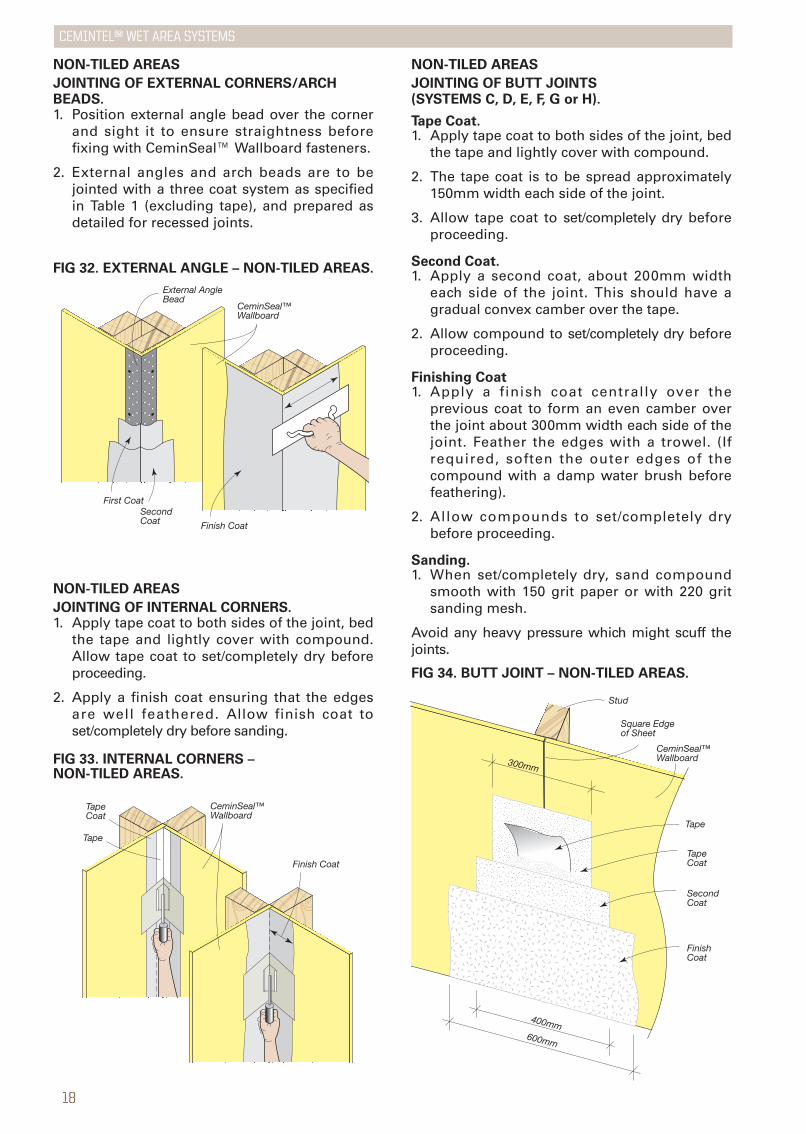
NON-TILED AREAS
JOINTING OF INTERNAL CORNERS.1. Apply tape coat to both sides of the joint, bed
the tape and lightly cover with compound.Allow tape coat to set/completely dry beforeproceeding.
2. Apply a finish coat ensuring that the edgesare well feathered. Allow finish coat toset/completely dry before sanding.
Finish Coat
Tape Coat
Tape
CeminSeal™Wallboard
FIG 33. INTERNAL CORNERS – NON-TILED AREAS.
FIG 32. EXTERNAL ANGLE – NON-TILED AREAS.
CeminSeal™Wallboard
External AngleBead
First CoatSecond Coat Finish Coat
NON-TILED AREAS
JOINTING OF EXTERNAL CORNERS/ARCHBEADS.1. Position external angle bead over the corner
and sight it to ensure straightness beforefixing with CeminSeal™ Wallboard fasteners.
2. External angles and arch beads are to bejointed with a three coat system as specifiedin Table 1 (excluding tape), and prepared asdetailed for recessed joints.
NON-TILED AREAS
JOINTING OF BUTT JOINTS(SYSTEMS C, D, E, F, G or H).
Tape Coat.1. Apply tape coat to both sides of the joint, bed
the tape and lightly cover with compound.
2. The tape coat is to be spread approximately150mm width each side of the joint.
3. Allow tape coat to set/completely dry beforeproceeding.
Second Coat.1. Apply a second coat, about 200mm width
each side of the joint. This should have agradual convex camber over the tape.
2. Allow compound to set/completely dry beforeproceeding.
Finishing Coat 1. Apply a finish coat centrally over the
previous coat to form an even camber overthe joint about 300mm width each side of thejoint. Feather the edges with a trowel. (Ifrequired, soften the outer edges of thecompound with a damp water brush beforefeathering).
2. Allow compounds to set/completely drybefore proceeding.
Sanding.1. When set/completely dry, sand compound
smooth with 150 grit paper or with 220 gritsanding mesh.
Avoid any heavy pressure which might scuff thejoints.
FIG 34. BUTT JOINT – NON-TILED AREAS.
300mm
Tape
Stud
Square Edgeof Sheet
CeminSeal™Wallboard
400mm600mm
Tape Coat
Second Coat
Finish Coat

19
CEMINTEL™ wet area systems
DECORATIONWhere regulations require an impervious finish,such as to the walls adjoining or behind a bath,or for walls of a shower recess, the CeminSeal™Wallboard in those areas must be finished withceramic tiles.
Other areas must be painted or wallpapered.
PAINTING.For best results, the surface of CeminSeal™Wallboard should be primed with a high qualitylatex primer before painting. Paintmanufacturers’ instructions are to be followedin all cases.
WALLPAPERING.For best results, the surface of CeminSeal™Wallboard should be sealed with a pigmented oilbase sealer before applying wallpaper or otherdecorative materials.
TILING.Tiles shall be installed in accordance withAS3958.1. Allowance must be made forexpansion/contraction by leaving a gap betweenadjoining tiles in vertical corners. Fill gap withflexible wet area sealant.
Refer to section on Control Joints for additionalrequirements.
The tiler must ensure that all loose dust andforeign matter are cleaned off the surfaces to betiled.
Ceramic Wall Tiles
Stud Stud
Stud
CeminSeal™ Wallboard
Expansion Gapfilled with Flexible Wet Area Sealant6mm Expansion Gapfilled with Sealant
Corner Blocking
WallPlate
WallPlate
WallPlate
PVC Angle Flashing to 1800mm min. above finished floor level
FIG 35. PROVISION FOR EXPANSION/CONTRACTION AT TILED INTERNAL CORNERS.
Proprietary tile adhesives that meet AS2358 :1990 ‘Adhesives for ceramic wall tiles andmosaics’ are recommended.*
Tiling to be in accordance with the tile adhesivemanufacturer’s instructions. Priming of jointsand/or board may be required. A compatible tileadhesive must be used to fix tiles to proprietarymembranes.
Spread adhesive onto the surface to a depth ofabout 3mm, then ‘rib’ in a horizontal directionwith a notched trowel having approximately4.5mm x 4.5mm notches.
*NOTE: That some adhesives require primingof joints and or sheets.
20
CEMINTEL™ wet area systems
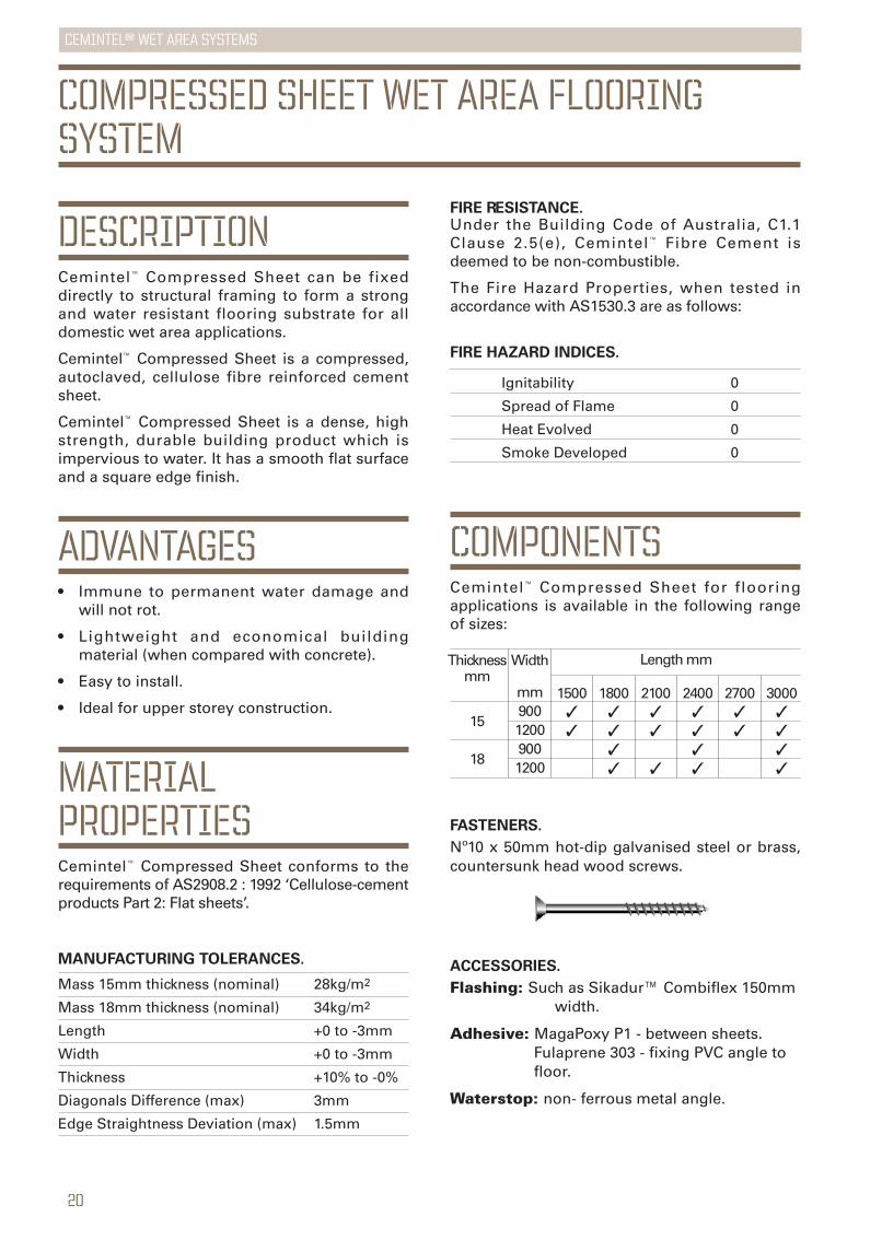
DESCRIPTIONCemintel™ Compressed Sheet can be fixeddirectly to structural framing to form a strongand water resistant flooring substrate for alldomestic wet area applications.
Cemintel™ Compressed Sheet is a compressed,autoclaved, cellulose fibre reinforced cementsheet.
Cemintel™ Compressed Sheet is a dense, highstrength, durable building product which isimpervious to water. It has a smooth flat surfaceand a square edge finish.
ADVANTAGES• Immune to permanent water damage and
will not rot.
• Lightweight and economical buildingmaterial (when compared with concrete).
• Easy to install.
• Ideal for upper storey construction.
MATERIALPROPERTIESCemintel™ Compressed Sheet conforms to therequirements of AS2908.2 : 1992 ‘Cellulose-cementproducts Part 2: Flat sheets’.
Ignitability 0
Spread of Flame 0
Heat Evolved 0
Smoke Developed 0
FIRE HAZARD INDICES.
Thicknessmm
15
18
Width
mm90012009001200
1500✓✓
1800✓✓✓✓
2100✓✓
✓
2400✓✓✓✓
2700✓✓
3000✓✓✓✓
Length mm
COMPONENTSCemintel™ Compressed Sheet for flooringapplications is available in the following rangeof sizes:
FASTENERS.
Nº10 x 50mm hot-dip galvanised steel or brass,countersunk head wood screws.
ACCESSORIES.
Flashing: Such as Sikadur™ Combiflex 150mm width.
Adhesive: MagaPoxy P1 - between sheets.Fulaprene 303 - fixing PVC angle to floor.
Waterstop: non- ferrous metal angle.
Mass 15mm thickness (nominal) 28kg/m2
Mass 18mm thickness (nominal) 34kg/m2
Length +0 to -3mm
Width +0 to -3mm
Thickness +10% to -0%
Diagonals Difference (max) 3mm
Edge Straightness Deviation (max) 1.5mm
MANUFACTURING TOLERANCES.
FIRE RESISTANCE.Under the Building Code of Australia, C1.1Clause 2.5(e), Cemintel™ Fibre Cement isdeemed to be non-combustible.
The Fire Hazard Properties, when tested inaccordance with AS1530.3 are as follows:
COMPRESSED SHEET WET AREA FLOORINGSYSTEM

21
CEMINTEL™ wet area systems
INSTALLATIONFIXING COMPRESSED SHEETS.Sheets may be fixed in place prior to or afterwall framing is installed.
All compressed sheet ends must be supportedby a framing member. Wherever possible plansheet layout to avoid the need to cut sheets.
Sheets must be screw fixed at 450mmmaximum centres along sheet edges and in thebody of the sheet.
Screws must be kept a minimum of 12mm fromthe edge of sheets and 50mm from corners.
Screw holes must be pre-drilled using amasonry bit, allowing 1mm clearance over thediameter of screw.
All sheet joints must be sealed using MegaPoxyP1, a two part water based epoxy adhesive, thatmust be mixed just prior to use. It is importantto ensure sheet edges are clean and free of anydust.
Adhesive must be applied to the edge of thefirst sheet once it is fixed in position. Butteradhesive along sheet edge, then positionsecond sheet.
Ensure sheets are pushed together tightly foradequate adhesion, and the joint is filled.
It is not acceptable to force adhesive into thejoint after both sheets have been fixed in place.
450mmmax
50mmfromcorners
Adhesivealong all joints
Cemintel™ Compressed Sheet
Joist
12mmfrom edges
Adhesive
Joist
Cemintel™Compressed Sheet
FIG 36. SHEET FIXING.
WATERPROOFINGCemintel™ Compressed Sheet may be fixed overtimber or steel joist systems.
Timber framing must comply with AS1684 :1992 ‘National Timber Framing Code’.
Steel framing must comply with AS3623 : 1993‘Domestic Metal Framing’.
For upper storey construction, the use ofdurable seasoned timber or composite steeljoists is recommended to minimise differentialmovement resulting from joist shrinkage.
Joists must have a minimum face width of38mm and should be spaced as follows:
15mm sheet – 450mm maximum centres.
18mm sheet – 600mm maximum centres.
Wherever possible joist and sheet layout shouldbe planned to ensure the long edges ofcompressed sheets are installed across the floorjoists, and to ensure the end of the sheet is fixedon the centre line of the joist.
Sheets that are fixed parallel to the floor joistsmust have both long edges continuouslysupported along the centre line of joists. Sheetends must also be fully supported by framing.
SHEET PREPARATIONWhen cutting or grinding fibre cement sheetsusing power tools, always ensure the work areais well ventilated. An approved dust mask(AS1715 and AS1716) and safety glasses(AS1337) must be worn. CSR recommends thathearing protection be worn where appropriate.
Refer to page 4 and 5 of this guide for detailedinformation
Wall sheeting
Continuous insitu membrane to shower recess floor, over angle and up walls
Shower Screen sealed with flexible sealant at floor and walls
150m
m m
in.
Waterstop fixed to floor
75mm min.
Mortar bed
Cemintel™ Compressed Sheet
22
CEMINTEL™ wet area systems
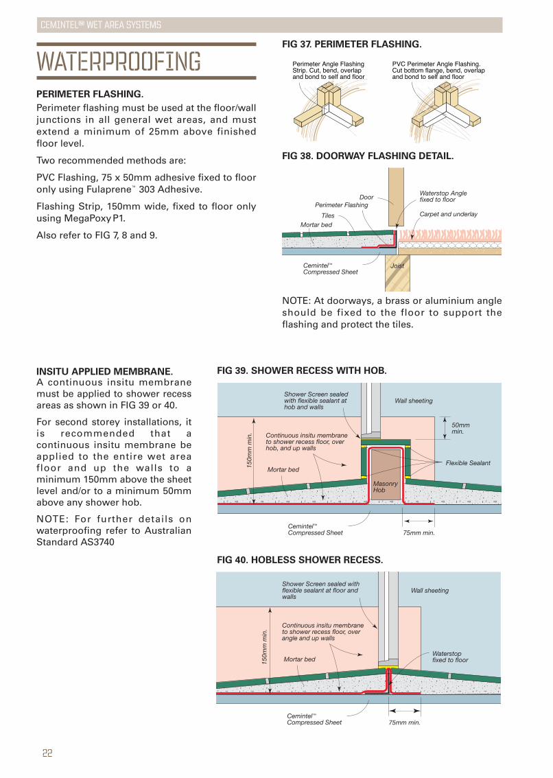
WATERPROOFINGPERIMETER FLASHING.
Perimeter flashing must be used at the floor/walljunctions in all general wet areas, and mustextend a minimum of 25mm above finishedfloor level.
Two recommended methods are:
PVC Flashing, 75 x 50mm adhesive fixed to flooronly using Fulaprene™ 303 Adhesive.
Flashing Strip, 150mm wide, fixed to floor onlyusing MegaPoxyP1.
Also refer to FIG 7, 8 and 9.
FIG 37. PERIMETER FLASHING.
PVC Perimeter Angle Flashing. Cut bottom flange, bend, overlap and bond to self and floor
Perimeter Angle Flashing Strip. Cut, bend, overlap and bond to self and floor
NOTE: At doorways, a brass or aluminium angleshould be fixed to the floor to support theflashing and protect the tiles.
FIG 39. SHOWER RECESS WITH HOB.
Wall sheeting
Continuous insitu membrane to shower recess floor, over hob, and up walls
Shower Screen sealed with flexible sealant at hob and walls
50mmmin.
150m
m m
in.
Masonry Hob
Flexible Sealant
75mm min.
Mortar bed
Cemintel™ Compressed Sheet
FIG 40. HOBLESS SHOWER RECESS.
FIG 38. DOORWAY FLASHING DETAIL.
Joist
Mortar bed
Cemintel™ Compressed Sheet
Waterstop Angle fixed to floor
Carpet and underlay
Door
Tiles
Perimeter Flashing
INSITU APPLIED MEMBRANE.A continuous insitu membranemust be applied to shower recessareas as shown in FIG 39 or 40.
For second storey installations, itis recommended that acontinuous insitu membrane beapplied to the entire wet areafloor and up the walls to aminimum 150mm above the sheetlevel and/or to a minimum 50mmabove any shower hob.
NOTE: For further details onwaterproofing refer to AustralianStandard AS3740
23
CEMINTEL™ wet area systems
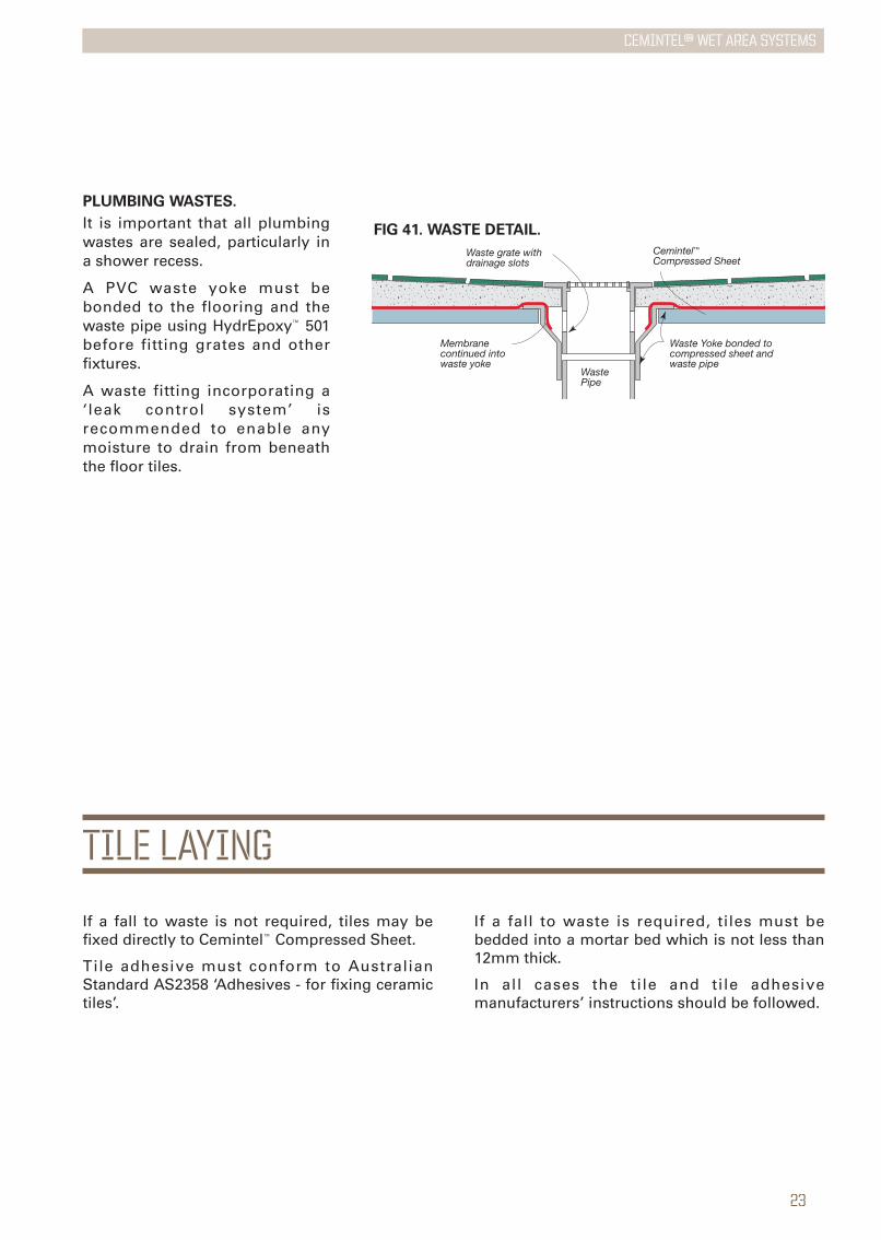
PLUMBING WASTES.
It is important that all plumbingwastes are sealed, particularly ina shower recess.
A PVC waste yoke must bebonded to the flooring and thewaste pipe using HydrEpoxy™ 501before fitting grates and otherfixtures.
A waste fitting incorporating a‘leak control system’ isrecommended to enable anymoisture to drain from beneaththe floor tiles.
If a fall to waste is not required, tiles may befixed directly to Cemintel™ Compressed Sheet.
Tile adhesive must conform to AustralianStandard AS2358 ‘Adhesives - for fixing ceramictiles’.
If a fall to waste is required, tiles must bebedded into a mortar bed which is not less than12mm thick.
In all cases the tile and tile adhesivemanufacturers’ instructions should be followed.
FIG 41. WASTE DETAIL.
WastePipe
Cemintel™ Compressed Sheet
Membrane continued into waste yoke
Waste grate with drainage slots
Waste Yoke bonded to compressed sheet and waste pipe
TILE LAYING
CEMINTEL™ wet area systemsCEMINTEL™ wet area systems
CEMINTEL RESIDENTIAL EXPRESSWALL™
GUARANTEECSR Building Products Limited warrants its FibreCement products to be free of defects in materialsand manufacture. If a CSR product does not meetour standard, we will, at our option, replace orrepair it, supply an equivalent product, or pay fordoing one of these.
This warranty excludes all other warranties andliability for damage or loss in connection withdefects in CSR's product, other than thosecompulsorily imposed by legislation, notably theTrade Practices Act.
HEALTH & SAFETYWARNING: Fibre Cement products containcrystalline silica. Repeated inhalation of fibrecement dust may cause lung scarring (silicosis) orcancer. Do not breathe the dust. When cuttingsheets, use the methods recommended in thisbrochure to minimise dust generation. If powertools are used, wear an approved dust mask(respirator). These precautions are not necessarywhen stacking, unloading or handling fibre cementproducts.
For further information and for a Material SafetyData Sheet, phone 1800 807 668.
©Cemintel™ Fibre Cement Systems, CSR Building Products Limited A.B.N. 55 008 631 356.
CEMINTEL™ FIBRE CEMENT SYSTEMs
wet area systemsjuly 2009
fc101cemintel™ fibre cement systems, csr building products limited, A.B.N 55 008 631 356
CONTACT DETAILS Cemintel™ Fibre Cement Sytems Web Site.
www.cemintel.com.au
Cemintel™ Fibre Cement Sytems Sales Support.
Telephone: 13 17 44. Facsimile: 1800 646 364.
CSR designLINK® Technical Support Service.
Telephone: 1800 621 117.
New South Wales and ACT.
376 Victoria Street, Wetherill Park NSW 2164.
Queensland.
768 Boundary Road, Coopers Plains QLD 4108.
Victoria.
277 Whitehall Street, Yarraville VIC 3013.
South Australia.
Lot 100 Sharp Court, Mawson Lakes SA 5095.
Western Australia.
19 Sheffield Road, Welshpool WA 6106.
Tasmania.
PO Box 61, Glenorchy TAS 7010.
Northern Territory.
Cnr Stuart Hwy & Angliss St, Berrimah NT 0828.
www.cemintel.com.au