Embed Size (px)
Citation preview

Installation and Operation Manual
GTC250A Gas Turbine Control for Generator or Compressor Applications
8262-1031
Manual 26433
DEFINITIONS
This is the safety alert symbol. It is used to alert you to potential personal injury hazards. Obey all safety messages that follow this symbol to avoid possible injury or death.
• DANGER—Indicates a hazardous situation which, if not avoided, will result in death or serious injury.
• WARNING—Indicates a hazardous situation which, if not avoided, could result in death or serious injury.
• CAUTION—Indicates a hazardous situation which, if not avoided, could result in minor or moderate injury.
• NOTICE—Indicates a hazard that could result in property damage only (including damage to the control).
• IMPORTANT—Designates an operating tip or maintenance suggestion.
The engine, turbine, or other type of prime mover should be equipped with an overspeed shutdown device to protect against runaway or damage to the prime mover with possible personal injury, loss of life, or property damage.
The overspeed shutdown device must be totally independent of the prime mover control system. An overtemperature or overpressure shutdown device may also be needed for safety, as appropriate.
Read this entire manual and all other publications pertaining to the work to be performed before installing, operating, or servicing this equipment. Practice all plant and safety instructions and precautions. Failure to follow instructions can cause personal injury and/or property damage.
This publication may have been revised or updated since this copy was produced. To verify that you have the latest revision, be sure to check the Woodward website:
www.woodward.com/pubs/current.pdf The revision level is shown at the bottom of the front cover after the publication number. The latest version of most publications is available at:
www.woodward.com/publications If your publication is not there, please contact your customer service representative to get the latest copy.
Any unauthorized modifications to or use of this equipment outside its specified mechanical, electrical, or other operating limits may cause personal injury and/or property damage, including damage to the equipment. Any such unauthorized modifications: (i) constitute "misuse" and/or "negligence" within the meaning of the product warranty thereby excluding warranty coverage for any resulting damage, and (ii) invalidate product certifications or listings.
To prevent damage to a control system that uses an alternator or battery-charging device, make sure the charging device is turned off before disconnecting the battery from the system.
To prevent damage to electronic components caused by improper handling, read and observe the precautions in Woodward manual 82715, Guide for Handling and Protection of Electronic Controls, Printed Circuit Boards, and Modules.
Woodward Governor Company reserves the right to update any portion of this publication at any time. Information provided by Woodward Governor Company is believed to be correct and reliable. However, no responsibility is assumed by Woodward Governor Company unless otherwise expressly undertaken.
© Woodward 2007 All Rights Reserved
Manual 26433 GTC250A Gas Turbine Control
Woodward i
Contents
ELECTROSTATIC DISCHARGE AWARENESS .................................................. III CHAPTER 1. GENERAL INFORMATION ........................................................... 1 Introduction ............................................................................................................. 1 General Description ................................................................................................ 1 Hardware ................................................................................................................ 1 Software Application Program ................................................................................ 3
CHAPTER 2. DESCRIPTION OF OPERATION ................................................... 5 Introduction ............................................................................................................. 5 Scope ...................................................................................................................... 5 Functional Block Diagram ....................................................................................... 6 Control Loops ......................................................................................................... 6
CHAPTER 3. INSTALLATION........................................................................ 10 Introduction ........................................................................................................... 10 Fuel Control Input/Output Signals ........................................................................ 10 Software Interface Tools Setup ............................................................................ 15 Configure Menu Descriptions ............................................................................... 21
CHAPTER 4. CONFIGURATION AND SERVICE SETUP PROCEDURES .............. 22 Introduction ........................................................................................................... 22 Tunable Upload/Download Function .................................................................... 23 Start Modes .......................................................................................................... 23 Alarm Sequence ................................................................................................... 24 Shutdown Sequence ............................................................................................ 25 Setup of the CDP/Fuel Limiter Curve ................................................................... 25 NOX Water Injection Setup ................................................................................... 25 NOX Steam Injection Setup .................................................................................. 26 Power Augmentation Steam Injection Setup ........................................................ 26
CHAPTER 5. TROUBLESHOOTING ............................................................... 27 Dynamic Response Problems .............................................................................. 27 Accel/Decel Curves Setup .................................................................................... 29 Poor Valve Response ........................................................................................... 31 Common SIO Port Configurations ........................................................................ 32 Serial Null Modem Cable Reference .................................................................... 32
CHAPTER 6. SERVICE OPTIONS ................................................................. 33 Product Service Options ....................................................................................... 33 Woodward Factory Servicing Options .................................................................. 34 Returning Equipment for Repair ........................................................................... 35 Replacement Parts ............................................................................................... 35 Engineering Services ............................................................................................ 36 How to Contact Woodward ................................................................................... 36 Technical Assistance ............................................................................................ 37
APPENDIX A. SYSTEM INPUT/OUTPUT SIGNAL LAYOUT .............................. 38 APPENDIX B. MODBUS LIST FOR 8262-1031 .............................................. 54 APPENDIX C. ALARM LIST ......................................................................... 74
GTC250A Gas Turbine Control Manual 26433
ii Woodward
Contents
APPENDIX D. SHUTDOWN LIST ................................................................... 76 APPENDIX E. CONFIGURATION AND SERVICE TUNABLES WORKSHEET ........ 77 APPENDIX F. PRE-INSTALLATION CONTROL INFORMATION CHECKLIST ........ 93 APPENDIX G. INTERFACING TO DISTRIBUTED IO & LADDER LOGIC (8262-1031 UNIT) ..................................................................................... 94 Adding Ladder Logic Programming into the GTC250A ........................................ 94 Distributed IO Pre-programmed into the GTC250A ............................................. 94
Illustrations and Tables Figure 2-1. GTC250A Functional Block Diagram ................................................... 6 Figure 3-1. AppManager Tool ............................................................................... 16 Figure 3-2. Initial WinPanel screen....................................................................... 18 Figure 3-3. OPC Connection screen .................................................................... 18 Figure 3-4. Initial SOS screen .............................................................................. 18 Figure 3-5. Ethernet Link IP address .................................................................... 19 Figure 3-6. Reading Control Information .............................................................. 19 Figure 5-1. Ratio Decay Cycle .............................................................................. 28 Figure 5-2. Proportional Gain Settings ................................................................. 29 Figure 5-3. Linearized Flow Schedule .................................................................. 30 Table 5-1. Valve Test Data ................................................................................... 31

Manual 26433 GTC250A Gas Turbine Control
Woodward iii
Electrostatic Discharge Awareness All electronic equipment is static-sensitive, some components more than others. To protect these components from static damage, you must take special precautions to minimize or eliminate electrostatic discharges. Follow these precautions when working with or near the control. 1. Before doing maintenance on the electronic control, discharge the static
electricity on your body to ground by touching and holding a grounded metal object (pipes, cabinets, equipment, etc.).
2. Avoid the build-up of static electricity on your body by not wearing clothing
made of synthetic materials. Wear cotton or cotton-blend materials as much as possible because these do not store static electric charges as much as synthetics.
3. Keep plastic, vinyl, and Styrofoam materials (such as plastic or Styrofoam
cups, cup holders, cigarette packages, cellophane wrappers, vinyl books or folders, plastic bottles, and plastic ash trays) away from the control, the modules, and the work area as much as possible.
4. Do not remove the printed circuit board (PCB) from the control cabinet
unless absolutely necessary. If you must remove the PCB from the control cabinet, follow these precautions:
• Do not touch any part of the PCB except the edges. • Do not touch the electrical conductors, the connectors, or the
components with conductive devices or with your hands. • When replacing a PCB, keep the new PCB in the plastic antistatic
protective bag it comes in until you are ready to install it. Immediately after removing the old PCB from the control cabinet, place it in the antistatic protective bag.
To prevent damage to electronic components caused by improper handling, read and observe the precautions in Woodward manual 82715, Guide for Handling and Protection of Electronic Controls, Printed Circuit Boards, and Modules.

GTC250A Gas Turbine Control Manual 26433
iv Woodward
Manual 26433 GTC250A Gas Turbine Control
Woodward 1
Chapter 1. General Information
Introduction This manual describes the GTC250A Digital Control System designed to control two-shaft gas turbines for compressor or generator applications. The manual should be used along with the standard Atlas-II™ hardware manual (26415), and therefore the scope of this document is only to describe details of the GTC250A application software functionality and assist the customer in configuration and start-up of the control. Refer to manual 26415 for information on hardware specifications, mounting information, wiring details, and adding distributed I/O to the system. Scope of Supply Item # Description 8262-1031 GTC250A—Atlas-II (Fuel Control and pre-programmed Profibus
Distributed I/O 1796-1043 CD—System Documentation & Software Tools Optional Add-ons Item # Description 8923-1025 Distributed I/O Kit (optional) 1784-505 Moore Industries AD590 Ambient Temperature Signal Converter 8900-067 Ambient Air Temperature Sensor (AD590) 5441-699 Relay Interface (12) FTM 5417-747 Relay FTM Interface Cable 8200-224 Servo Position Controller (SPC)
General Description The Woodward GTC250A Atlas-II Digital Control System is a configurable control system for gas turbines that produces a fuel demand output to control speed, load, pressure, and temperature. In addition to this, the control allows packager or user programming by use of an auxiliary programming tool. For a given GTC model, the maximum I/O available is fixed and has been pre-programmed into the unit. If additional I/O is required, the customer should inquire about other models of the GTC family.
Hardware The GTC250A Atlas-II Digital Control is designed to be bulkhead mounted in a control panel. The complete unit contains an A5200 CPU module with actuators, 3 Analog Combo modules, Profibus interface module for distributed I/O and a Power Supply board. In addition, the system can include an optional relay Field Termination Module (FTM) and/or optional kits that include Distributed I/O modules and cables. These components are designed for DIN rail mounting in the control cabinet.

GTC250A Gas Turbine Control Manual 26433
2 Woodward
The CPU module controls the system. The I/O modules interface the CPU module to the outside world, permitting it to sense digital and analog inputs and to issue analog and discrete outputs. Optional relays are available for the system to isolate the system's discrete output circuits from the field wiring. Power Requirements The Atlas-II Digital Control System requires an 18-32 Vdc input supply voltage. Physical Description For further details on the physical hardware, refer to the Atlas-II product manual 26415. A5200 CPU Module The A5200CPU runs under a VxWorks® * real time operating system and follows the instructions of the application program, which controls all of the input and output circuits of the GTC250A Atlas-II Control.
*—VxWorks is a trademark of Wind River Systems, Inc. The CPU module has the following Communications Ports: Ethernet 100BT 4-10/100 Base-TX Ethernet ports used for Modbus® * communication and service tools.
*—Modbus is a trademark of Schneider Automation Inc. Serial COM 1 This port is a dedicated operating system debug port and should not be used. Serial COM 2 The COM 2 Serial Port is configured for use as a Modbus interface on this control. If used, a serial isolation adapter must be used. I/O Modules Every I/O module has a FAULT LED that is controlled by the CPU. During every initialization of the system, the CPU turns these LEDs on. The CPU then individually tests each I/O module. If an I/O module fails any test, the FAULT LED remains on. The FAULT LED remaining on after the diagnostics have run may mean that the module has failed a test, or it may mean that the module is not correctly declared in the GAP application. For further details on the specific hardware modules installed in this system refer to the Atlas-II product manual 26415. The I/O signals for GTC systems are divided into two groups, the Atlas-II I/O and the Distributed I/O.
Manual 26433 GTC250A Gas Turbine Control
Woodward 3
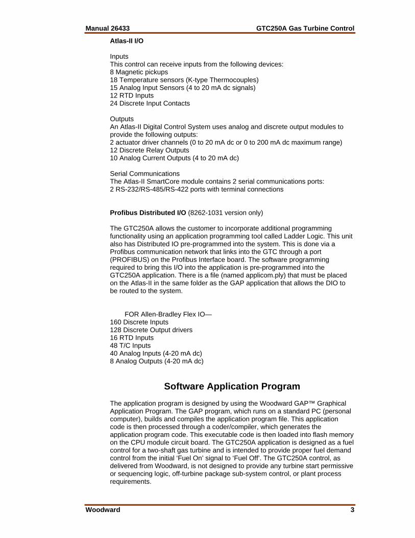
Atlas-II I/O Inputs This control can receive inputs from the following devices: 8 Magnetic pickups 18 Temperature sensors (K-type Thermocouples) 15 Analog Input Sensors (4 to 20 mA dc signals) 12 RTD Inputs 24 Discrete Input Contacts Outputs An Atlas-II Digital Control System uses analog and discrete output modules to provide the following outputs: 2 actuator driver channels (0 to 20 mA dc or 0 to 200 mA dc maximum range) 12 Discrete Relay Outputs 10 Analog Current Outputs (4 to 20 mA dc) Serial Communications The Atlas-II SmartCore module contains 2 serial communications ports: 2 RS-232/RS-485/RS-422 ports with terminal connections Profibus Distributed I/O (8262-1031 version only) The GTC250A allows the customer to incorporate additional programming functionality using an application programming tool called Ladder Logic. This unit also has Distributed IO pre-programmed into the system. This is done via a Profibus communication network that links into the GTC through a port (PROFIBUS) on the Profibus Interface board. The software programming required to bring this I/O into the application is pre-programmed into the GTC250A application. There is a file (named applicom.ply) that must be placed on the Atlas-II in the same folder as the GAP application that allows the DIO to be routed to the system. FOR Allen-Bradley Flex IO— 160 Discrete Inputs 128 Discrete Output drivers 16 RTD Inputs 48 T/C Inputs 40 Analog Inputs (4-20 mA dc) 8 Analog Outputs (4-20 mA dc)
Software Application Program The application program is designed by using the Woodward GAP™ Graphical Application Program. The GAP program, which runs on a standard PC (personal computer), builds and compiles the application program file. This application code is then processed through a coder/compiler, which generates the application program code. This executable code is then loaded into flash memory on the CPU module circuit board. The GTC250A application is designed as a fuel control for a two-shaft gas turbine and is intended to provide proper fuel demand control from the initial ‘Fuel On’ signal to ‘Fuel Off’. The GTC250A control, as delivered from Woodward, is not designed to provide any turbine start permissive or sequencing logic, off-turbine package sub-system control, or plant process requirements.

GTC250A Gas Turbine Control Manual 26433
4 Woodward
One of the special & unique features of GAP is the ability to combine multiple source GAP programs into one compiled/executable program. This allows for separate engineering control of specific areas of programming logic. The GTC family uses a programming architecture that is best represented in the following illustration. Third-Ring (blue) – Ladder Logic Second-Ring (red) - GAP CORE (yellow) - GAP The CORE file GAP program contains the main control loop functions for the control of the turbine fuel-metering valve. The next chapter shows a functional block view of this logic and explains its functions in more detail. This file is designed and engineering controlled by Woodward and is not intended to be changed by the customer. The Second-Ring file GAP program contains all of the control system I/O blocks of the system, interfaces to the CORE and all communications software for the system. This file is initially designed and supplied by Woodward, but in some cases can be modified by the customer for package ancillary devices, sub-systems, interface to other distributed I/O and communications to customer devices. The GTC250A control includes a built-in programming tool named Ladder Logic. This allows packagers or users to construct a custom program “Third-Ring” (if desired) to control such things as turbine sequencing logic or control of ancillary turbine equipment. This program can utilize the additional I/O pre-programmed into the GTC250A. The program is created by a separate software programming tool and is loaded into the control during runtime. It has access to all GAP variables, but can only write into pre-defined memory locations and control a limited amount of the total system I/O.

Manual 26433 GTC250A Gas Turbine Control
Woodward 5
Chapter 2. Description of Operation
Introduction This chapter describes the operation and features included in the GTC250A system for control of a gas turbine driving a generator or a compressor.
Scope The control has been divided into major functions for this description. Many of these functions have sub-functions, and all of these may not be utilized in your specific unit. The major functions of this Atlas-II™ Digital Control System include: • Ambient Temperature Sensing • Speed Sensing • Turbine Inlet Temperature Sensing • Compressor Discharge Pressure (CDP) Sensing • Exhaust Gas Temperature (EGT) Sensing • Analog and Digital Outputs • Speed Reference Logic • Start Ramp and Start Control Logic • Speed Control of Gas Generator Shaft (GG) • Speed/Load Control of Power Turbine Shaft (PT) • CDP Limiting Control • EGT Limiting Control • Megawatt Limiting Control • Acceleration and Deceleration Control • Fuel Transfer Logic • NOX Valve Demand • Power Augmentation Valve Demand • Flameout Detection (both UV detectors and EGT temp sensing)
GTC250A Gas Turbine Control Manual 26433
6 Woodward
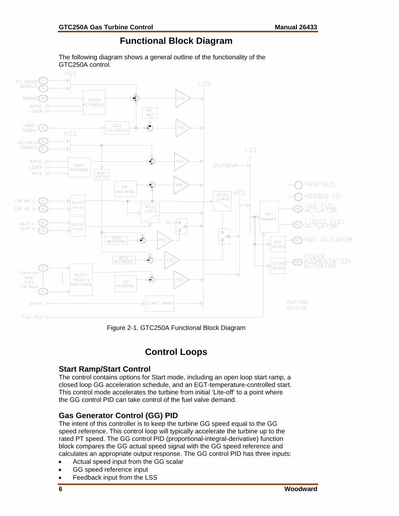
Functional Block Diagram The following diagram shows a general outline of the functionality of the GTC250A control.
Figure 2-1. GTC250A Functional Block Diagram
Control Loops Start Ramp/Start Control The control contains options for Start mode, including an open loop start ramp, a closed loop GG acceleration schedule, and an EGT-temperature-controlled start. This control mode accelerates the turbine from initial ‘Lite-off’ to a point where the GG control PID can take control of the fuel valve demand. Gas Generator Control (GG) PID The intent of this controller is to keep the turbine GG speed equal to the GG speed reference. This control loop will typically accelerate the turbine up to the rated PT speed. The GG control PID (proportional-integral-derivative) function block compares the GG actual speed signal with the GG speed reference and calculates an appropriate output response. The GG control PID has three inputs: • Actual speed input from the GG scalar • GG speed reference input • Feedback input from the LSS
Manual 26433 GTC250A Gas Turbine Control
Woodward 7
Power Turbine Control (PT) PID The intent of this controller is to maintain desired speed of the PT shaft. Under normal operating conditions, the unit will be loaded while in this mode and maintain speed control from zero load to maximum load. The PT control PID compares the PT actual speed signal with the PT speed reference and calculates an appropriate output response. The PT control PID has three inputs: • Actual speed input from the PT scalar • PT speed reference input • Feedback input from the LSS ACCEL Control (Curve Schedule & PID) The accel schedule determines the maximum amount of fuel allowed, during acceleration. This demand is driven by either a configurable curve (based on CDP) or by a PID control on the GG speed derivative. The CDP versus Fuel Demand accel limit curve is a required configuration by the user. It will determine the maximum amount of fuel allowed for the current CDP. The speed derivative accel PID is an option that can also be used. The maximum amount of fuel allowed is determined by a speed vs. speed derivative curve. Both of these control parameters feed into the LSS bus. If the value is the lowest on the LSS, then its schedule controls the LSS. The PID option can be selected during the configuration of the unit. Temperature Limiting Control (EGT) PID The EGT PID block compares the actual EGT signal with the reference EGT signal and generates an appropriate output response signal. The EGT control PID is typically used as a limiter on the high end of the load curve of the turbine. It is also used in the GTC as an option on startup to limit the fuel flow until closed loop speed control can be reached (typically at GG idle). It will limit the fuel demand to the turbine once the EGT temperature reaches the EGT reference setpoint. The EGT Control PID has three inputs: • Calculated average temperature from all validated EGT T/C inputs • EGT temperature reference setpoint • Feedback from the LSS Megawatt Limiting Control (MW_LIM) PID The MW PID block compares the actual MW signal (or calculated MW load based on turbine CDP) with the reference MW signal and generates an appropriate output response signal. The MW control PID is typically used as a limiter on the high end of the load curve of the turbine. It will limit the fuel demand to the turbine once the MW output reaches the MW reference setpoint. The MW Control PID has three inputs: • Actual or calculated MW load input • MW limiter reference setpoint • Feedback from the LSS Pressure Limiting Control (CDP) PID The CDP PID block compares the actual CDP signal with the reference CDP signal and generates an appropriate output response signal. The CDP control PID is typically used as a limiter on the high end of the load curve of the turbine. It will limit the fuel demand to the turbine once the CDP pressure reaches the CDP reference setpoint. The CDP Control PID has three inputs: • Validated CDP from all valid CDP inputs: • CDP reference setpoint • Feedback from the LSS
GTC250A Gas Turbine Control Manual 26433
8 Woodward
Compressor Stall Detection Logic The control includes the option of using Compressor Stall Detection algorithms. The control monitors the CDP signals at a very high-speed data rate and then calculates a derivative of this signal. When this calculation exceeds the OEM defined limits of this turbine parameter, a control shutdown is initiated. LSS Bus The low signal select (LSS) bus selects the lowest of the GG PID, PT PID, EGT PID, CDP PID, MW Limiter, Start Ramp, or the accel schedule signals, and passes it to the HSS bus. Whichever signal is calling for the lowest fuel is the one used for LSS bus output. DECEL Control (Curve Schedule or PID) The decel schedule determines the minimum amount of fuel allowed during deceleration. This demand is determined by a curve that is based on CDP as the forcing function or by a PID control on the GG speed derivative signal. It uses one of these signals to determine the minimum amount of fuel allowed. It then outputs this value to the HSS. If the value is the highest on the HSS, the decel schedule controls the HSS. HSS Bus The HSS bus receives the output of the LSS bus and the decel schedule as input. Whichever of these inputs is higher will be the signal sent to the output of the HSS bus. This output is responsible for setting the turbine fuel valve position to maintain the requested turbine parameter. LSS Bus (LSS_2) A second low signal select (LSS) bus exists downstream of the HSS. This is where the Shutdown command is invoked to chop fuel flow to the turbine. Fuel Demand This block is the true 0–100% fuel demand being commanded from the fuel control. Actuator Driver The actuator driver converts the 0-to-100% software control signal to a proportional actuator drive current signal. This can be configured for a 4–20 mA or 0–200 mA drive signal. An input from the shutdown input can override the control signal and cause the actuator to go to minimum-fuel position or shutdown. The shutdown circuit also has short and open coil fault detection. The actuator translates the signal from the electronic control into mechanical force to position the fuel valve. There are separate actuator drive outputs for gas and liquid fuel. Fuel Transfer Logic The control has the capability to run on gas or liquid fuel and the ability to make on-line fuel transfers between the two fuels. It is important to note that the packager/user will need to gather the necessary fuel property and valve flow schedule information to correctly configure the unit to make smooth on-line fuel transfers.
Manual 26433 GTC250A Gas Turbine Control
Woodward 9
NOX Valve Demand The control has the capability to control the turbine emissions through the modulation of a NOX control valve. This logic provides a 4–20 mA output that is designed to be the demand signal to a driver for positioning of a water or steam injection valve. The logic has configuration choices for the forcing function input to a tunable curve schedule blocks. There are separate schedule curves for gas and liquid fuel as well as ‘ratio multipliers’ and raise and lower ramps to adjust the NOX flow to the desired demand. Power Augmentation Valve Demand The control has the capability to provide the demand signal for a steam injection valve. Some installed turbine designs incorporate an optional power augmentation system. This logic provides a 4–20 mA output that is designed to be the demand signal to a driver for positioning of a steam injection valve for this purpose. There are options for steam flow schedules and a raise & lower ramp to adjust the demand to the desired levels.

GTC250A Gas Turbine Control Manual 26433
10 Woodward
Chapter 3. Installation
Introduction A detailed list of the Atlas-II™ I/O signal layout including channel allocation, wiring terminations, descriptions, and range information is found in Appendix A. This chapter describes details of the signals that the GTC250A is programmed to handle. The control wiring diagrams in Appendix A also identify which signals are required and which are optional.
Fuel Control Input/Output Signals Speed Sensing The function of speed sensing is to monitor turbine speed. The sub-functions are: • Speed Sensors • Speed Derivative • Sensor Fault Detection • Speed Switches Speed Sensors There are four speed sensors in this system, two for GG and two for PT. The digital speed sensor I/O board receives input from the speed sensors on the turbine and converts this speed signal to a usable form for the control. The two speed signals for each shaft are high-signal selected with only the one indicating the higher speed being sent to the control PIDs. Speed Derivative The speed sensor input blocks also generate a derivative of the speed, which gives the control a high frequency calculation of the rate of change in speed over time. This signal is high signal selected, and this value is used to control acceleration and deceleration of the turbine. Sensor Fault Detection Sensor fault detection is done in the application software. On detection of a sensor fault, a signal is generated for activation of associated indicators and alarms. Failure of both signals from the same shaft will cause a shutdown. An alarm also exists for annunciating a speed difference between redundant sensors. Speed Switches In the software there are three speed switches for GG and three speed switches for PT. These speed switches are configurable for any speed and are used to drive relay outputs. These outputs can be used by other systems. There is also an overspeed switch for GG and one for PT. Each of these switches can be configured to activate at any speed. Each switch also initiates a potential shutdown or alarm when activated.
Manual 26433 GTC250A Gas Turbine Control
Woodward 11
Speed Reference The speed reference produces the desired speed-setting signal and sends it to the speed controller. The sub-functions are: • Speed Setting • GG Ambient Bias • Remote Speed Setting Speed Setting The GG and PT speed settings are raised or lowered by closing the associated contact. The rate at which the reference changes can also be selected. Each speed reference has both an upper and a lower limit position. The speed setting at each of these positions is a tunable value. Each speed reference also includes relay options to indicate when that speed reference is at the upper and lower limits. GG Ambient Bias There is an option to bias the GG speed or the GG reference input from an ambient temperature bias block. If the ambient temperature input fails, a fixed value (which is configurable) bias signal is used. Remote Speed Setting The PT speed setting can be controlled by a remote signal. The ENABLE contact enables remote speed setting. When enabled, the speed setting can be changed by varying a remote 4-to-20 mA signal. At this time all PT associated switch contacts (RAISE, LOWER, FAST, and INSTANT) will be disabled. Ambient Temperature Sensor The control is designed to receive an ambient temperature signal via a single 4–20 mA input, a thermocouple input, or via a single or redundant RTD input. It is very common for this ambient temperature to be sensed by an AD590. There is an optional kit item that can be included with the GTC products to convert this signal. The AD590 microamp signal is converted to a milliamp signal through the Moore Industries device. This device has been programmed with a microamp to milliamp/temperature conversion chart that converts the value into a 4–20 mA signal. The ambient temperature sensor signal is converted to a digital signal in the Atlas-II Digital Control System and can be configured to bias any of the following turbine parameters: GG Speed, GG reference, and/or the EGT reference. If the ambient temperature input signal fails, a fixed-value signal (tunable) is used as the bias signal. Exhaust Gas Temperature (EGT) The EGT section of this control includes the following sub-sections: • EGT Sensing • Temperature Reference • Temperature Switch Output Relay Signals
GTC250A Gas Turbine Control Manual 26433
12 Woodward
EGT Sensing Two methods of sensing EGT are available, one 4–20 mA summary EGT input or multiple thermocouples. When the summary method is selected, a single 4–20 mA input senses the EGT. The system feeds the temperature information from this signal to the three temperature switches, the overtemp switch, and the EGT control PID. When the multiple-thermocouple method is used, the EGT is sensed by a number of type K thermocouples (configurable from 1 to 18). Cold Junction compensation is done on the Atlas-II I/O module, but there is an option to bring in a CJ sensor from a remote location, if the appropriate T/C wiring is not run all the way to the Atlas-II. The temp spread monitor block calculates the average reading of the thermocouples. It excludes any that are outside of the allowed spread or those T/C that have failed. The temp spread monitor block and the subtract block calculate the difference between the highest and lowest readings of the thermocouples that are included in the average. The average is sent to the three temperature switches, the overtemp switch, and the EGT control PID. Configurable alarms and shutdowns are available for each T/C, number of failed T/Cs, and excessive spread. Temperature Reference The EGT Reference is set by a tunable variable and can be configured to use an ambient temperature bias. There is an option to use the EGT control for starting the unit. The control has additional temperature setpoints that are used for this option. Temperature Switches In the software there are two temperature switches for the EGT. These temp switches are configurable for any temperature setpoint and are used to drive relay outputs. These outputs can be used by other systems. Flameout Detection Logic (UV) The Flameout section of this control includes the following sub-sections: • UV Detector (discrete inputs) Sensing • EGT Temperature Monitoring • GG Speed Monitoring Ultra-Violet Flame Sensor Detectors If UV detectors are used, the control will monitor these signals to confirm that ignition exists in the combustor. Both single and redundant sensors are supported. Flame is recognized by the control by a True signal on the discrete contacts. EGT Temperature Monitoring The control uses EGT temperature logic to monitor for a ‘Lite-off’ detection in the combustor. This setpoint for this software switch is set at 400 °F (204 °C). If during any valid turbine running sequence the EGT temperature drops below this level, the control will consider this a lost flame condition and initiate a shutdown. The control can be configured to use either one or both of these options. GG Speed Monitoring This method monitors the GG shaft for speed to be greater than a programmed setpoint. Once this speed is reached, the control monitors for the speed to drop 200 rpm below this speed to determine that the unit has flamed out. Compressor Discharge Pressure (CDP) The CDP section of this control includes the following sub-sections: • CDP Sensing • CDP Derivative Calculation
Manual 26433 GTC250A Gas Turbine Control
Woodward 13
CDP Sensing The compressor discharge pressure (CDP) is sensed by a 4-to-20 mA pressure transducer. There are two 4-to-20 mA pressure signals available. The selection of the value that is used is configurable and can be an average, mean, HSS, or LSS. This value is then used by the control for pressure control and fuel schedules. CDP Derivative Calculation The CDP sensor input blocks also generate a derivative of this signal, which gives the control a high frequency calculation of the rate of change of compressor discharge pressure over time. This signal is high signal selected and this value is used in certain turbine operation protection algorithms. Megawatt Sensor (MW) The MW section of this control includes the following sub-section: • MW Sensing MW Sensing The megawatt load (MW) is sensed by a 4-to-20 mA load transducer. There is a 4-to-20 mA MW load sensor input signal available for applications driving generators. This value is then used by the control for load control/droop feedback when running the unit against a utility grid. Discrete Inputs Twenty-four discrete inputs are available as direct inputs into the Atlas-II I/O. These ‘high-speed’ input signals are used to direct the actions and functions of the fuel control. The following 20 are fixed and the other four are configurable. The * on the active state means that this state can be altered in configuration. In the programmable version of the GTC250A, each of these inputs can be configured to be used as shown or reallocated for use in a Ladder Logic program. Active State 1. Shutdown (Fuel Off) * TRUE = No external Shutdowns 2. Start/Run * TRUE = Start / Fuel ON 3. System Reset (ALM & SD) TRUE = Reset Alarm/Shutdown 4. System Acknowledge (ALM & SD) TRUE = Acknowledge Alarm/Shutdown 5. GG Reference Lower TRUE = Lower GG Speed Setpoint 6. GG Reference Raise TRUE = Raises GG Speed Setpoint 7. GG Reference Select Fast Rate TRUE = GG Speed Setpoint Rate = Fast 8. GG Reference Select Instant Rate TRUE = GG Speed Setpoint Rate = Instant 9. PT Reference Lower TRUE = Lower PT Speed Setpoint 10. PT Reference Raise TRUE = Raise PT Speed Setpoint 11. PT Reference Fast Rate TRUE = PT Speed Setpoint Rate = Fast 12. GG Speed and EGT Temp Signals
Failed Override TRUE = Override these sensor failures 13. PT Speed Signal Failed Override TRUE = Override PT sensor failures 14. Fuel Selection/Transfer TRUE = Liquid Fuel (False = Gas Fuel) 15. Enable Remote PT Reference Setpoint TRUE = Actively follow remote setpoint 16. Enable NOX Valve Control TRUE = Turn on NOX valve control 17. Isoch/Droop Select * TRUE = Go to Isoch (GenBrkr Open) 18. Enable Power Augmentation
Valve Control TRUE = Turn on Power Aug. valve control 19. Flame Detector A TRUE = Flame Detected 20. Flame Detector B TRUE = Flame Detected

GTC250A Gas Turbine Control Manual 26433
14 Woodward
Actuator Driver Outputs This system includes two actuator drivers, one for the gaseous-fuel actuator and one for the liquid-fuel actuator. Each of the actuator drivers receives a fuel demand signal and sends a proportional drive current signal to its actuator. Each actuator, in turn, controls the flow of one type of fuel. The outputs are configurable as 4–20 mA or 0–200 mA. These outputs are proportional drivers only—if integrating drivers are required, inquire about the Woodward Servo Position Controller (SPC). Analog Outputs The system includes ten analog outputs. These readout signals are 4–20 mA signals for driving readouts or sending to other plant system controls. Each of these signals is configurable to be driven via the auxiliary program or by the fuel control. Each of these analog outputs can be configured to be driven by one of the functions shown below. These are setup via a tunable ‘menu’ on the GAP Configuration sheets that is most conveniently done in Monitor GAP mode. • PT Actual Speed Readout • PT Reference Speed Readout • Fuel Valve Demand Readout (Total) • Gas Fuel Valve Demand Readout • Liquid Fuel Valve Demand Readout • Exhaust Gas Temperature Readout • GG Reference Speed Readout • GG Actual Speed Readout • Compressor Discharge Pressure Readout • MW Load Readout • NOX Valve Demand • Power Augmentation Valve Demand • Output from Modbus AW • Output from Ladder Logic • Customer Analog Output Relay Driver Outputs Twelve relay driver outputs are available from the Atlas-II I/O. These signals are used to indicate the function or status of the control or turbine. The first three outputs for SHUTDOWN, ALARM and HEALTH relays are fixed outputs. The SHUTDOWN and HEALTH signals (1 & 3) are normally energized to reflect a healthy GTC250A with no shutdowns present. The ALARM signal (2) along with all of the others is normally de-energized, and the control energizes these outputs when the condition shown is reached. The other nine signal outputs are configurable to be driven via the auxiliary program or by the fuel control. The default status for each one is to be driven by the fuel control and those functions are shown below.
Manual 26433 GTC250A Gas Turbine Control
Woodward 15
• SHUTDOWN Summary • ALARM Summary • Summary Horn (Alm or SD) Output • Unit in ISOCH • Unit in Droop • PT Reference at Low Limit • GG Speed Switch 1 • GG Speed Switch 2 • GG Speed Switch 3 • PT Speed Switch 1 • PT Speed Switch 2 • PT Speed Switch 3 • EGT Temperature Switch 1 • EGT Temperature Switch 2 • EGT Temperature Switch 3 • GG Speed in Control • PT Speed in Control • EGT Temp in Control • Start Ramp in Control • MW Load in Control • Running on 100% Gas Fuel • Running on 100% Liquid Fuel • NOX Valve Control Active • Output from Modbus BW • Output from Ladder Logic • Customer Defined
Software Interface Tools Setup Apply Power to the GTC250A At power-up, the GTC250A runs through its boot-up routine and performs a set of initial diagnostics to verify CPU, memory, I/O initialization, and bus health. This boot-up routine takes approximately a minute to execute. During this time, the control’s green run and red status LEDs on the CPU and I/O modules should be on. When boot-up is complete, the application program code begins running, the control outputs will be enabled, and system control will begin—the control’s red status LEDs will turn off and should remain off as long as the control is running. Install Control Assistant Software Both Woodward’s AppManager and Control Assistant configuration and service tool may be downloaded at no cost from the Woodward website (www.woodward.com/ic/software). As an alternative, an Install version of these software tools are included on the System documentation CD that came with the control. Connect PC to GTC250A The connection of a computer is only required for calibration and setup of the GTC250A. The computer and service interface software program are not required or necessary for normal operation of the control. You will need to connect a standard Ethernet cable between the Ethernet port # 1 of the Atlas-II A5200 CPU module on the GTC250A and a user PC per the control wiring diagram (Appendix A - 9971-1270). For information on the cable or communication port settings, see the troubleshooting section of this manual.
GTC250A Gas Turbine Control Manual 26433
16 Woodward
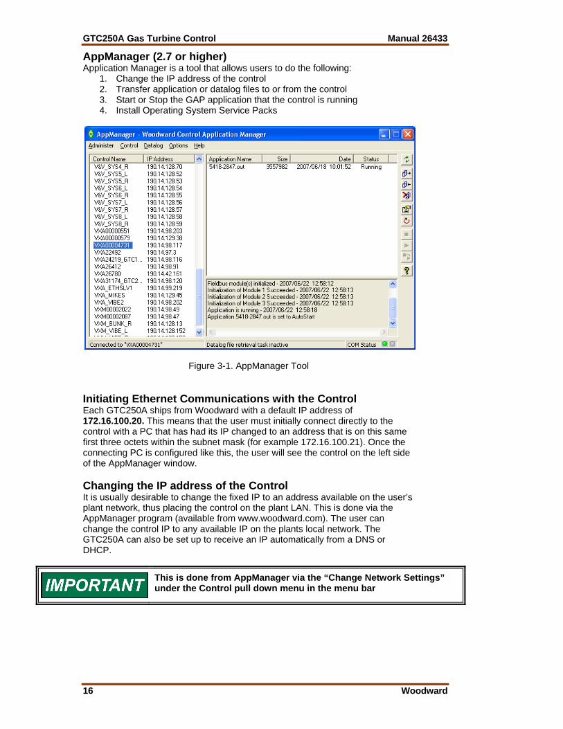
AppManager (2.7 or higher) Application Manager is a tool that allows users to do the following:
1. Change the IP address of the control 2. Transfer application or datalog files to or from the control 3. Start or Stop the GAP application that the control is running 4. Install Operating System Service Packs
Figure 3-1. AppManager Tool Initiating Ethernet Communications with the Control Each GTC250A ships from Woodward with a default IP address of 172.16.100.20. This means that the user must initially connect directly to the control with a PC that has had its IP changed to an address that is on this same first three octets within the subnet mask (for example 172.16.100.21). Once the connecting PC is configured like this, the user will see the control on the left side of the AppManager window. Changing the IP address of the Control It is usually desirable to change the fixed IP to an address available on the user’s plant network, thus placing the control on the plant LAN. This is done via the AppManager program (available from www.woodward.com). The user can change the control IP to any available IP on the plants local network. The GTC250A can also be set up to receive an IP automatically from a DNS or DHCP.
This is done from AppManager via the “Change Network Settings” under the Control pull down menu in the menu bar

Manual 26433 GTC250A Gas Turbine Control
Woodward 17
Control Assistant (3.4 or higher) Control Assistant is the primary service interface tool needed to configure the control, manage tunable values, trend values within the control, and view ‘datalog’ files (which are high speed data files that the control creates upon chosen events). The GTC250A is programmed to interface with this tool via an Ethernet connection from port 1 of the control to a user PC via the Woodward ServLink to OPC Server (SOS) communication utility. SOS is included in the Control Assistant installation and will launch automatically when needed. WinPanel (Tool within Control Assistant) WinPanel is a typical Windows application that provides a powerful and intuitive interface. The menu structures are familiar to Windows users. Variable navigation is provided through the Explorer window similar to the Explorer in Windows. The WinPanel tool within Control Assistant permits you to talk to the GTC250A via the Ethernet port on the CPU. You can use WinPanel to monitor values, read fault messages, or issue instructions to the GTC250A System. The WinPanel tool runs on a laptop or desktop PC and utilizes standard Windows dialog boxes and Explorer windows to allow the user to create ‘Inspector’ files of any fields available in the application software. This tool will allow you to access the service or configuration screens through an automatically created ‘inspector’ file. Software setup for the GTC250A begins with the Software Configuration & Service Tunables Worksheet. When the worksheet is completed, the values are then entered into the GTC250A with the WinPanel tool. This tool can also be used to upload (from the control to a file on the user PC) the tunable settings from the control. This file then can be downloaded (from the user PC to the control) into another control of the same part number and revision number. Keep this tunable file archived, as it will simplify configuration of other spare units and aid technical support in commissioning troubleshooting. An “inspector” provides a window for real-time monitoring and editing of all control Configuration and Service Menu parameters and values. Custom “inspectors” can easily be created and saved. Each window can display up to 28 lines of monitoring and tuning parameters without scrolling. The number with scrolling is unlimited. Two windows can be open simultaneously to display up to 56 parameters without scrolling. Tunable values can be adjusted at the inspector window. Initial GTC250A Communications: Before communications can begin between the WinPanel program and a control, a service interface definition file must be created. Once this network definition file is created and saved, it never has to be recreated, unless a new program is loaded into the control.
GTC250A Gas Turbine Control Manual 26433
18 Woodward
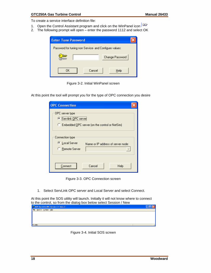
To create a service interface definition file: 1. Open the Control Assistant program and click on the WinPanel icon 2. The following prompt will open – enter the password 1112 and select OK
Figure 3-2. Initial WinPanel screen At this point the tool will prompt you for the type of OPC connection you desire
Figure 3-3. OPC Connection screen
1. Select ServLink OPC server and Local Server and select Connect. At this point the SOS utility will launch. Initially it will not know where to connect to the control, so from the dialog box below select Session / New
Figure 3-4. Initial SOS screen
Manual 26433 GTC250A Gas Turbine Control
Woodward 19
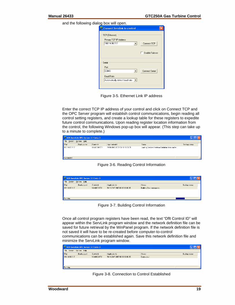
and the following dialog box will open.
Figure 3-5. Ethernet Link IP address Enter the correct TCP IP address of your control and click on Connect TCP and the OPC Server program will establish control communications, begin reading all control setting registers, and create a lookup table for these registers to expedite future control communications. Upon reading register location information from the control, the following Windows pop-up box will appear. (This step can take up to a minute to complete.)
Figure 3-6. Reading Control Information
Figure 3-7. Building Control Information Once all control program registers have been read, the text “Dflt Control ID” will appear within the ServLink program window and the network definition file can be saved for future retrieval by the WinPanel program. If the network definition file is not saved it will have to be re-created before computer-to-control communications can be established again. Save this network definition file and minimize the ServLink program window.
Figure 3-8. Connection to Control Established
GTC250A Gas Turbine Control Manual 26433
20 Woodward
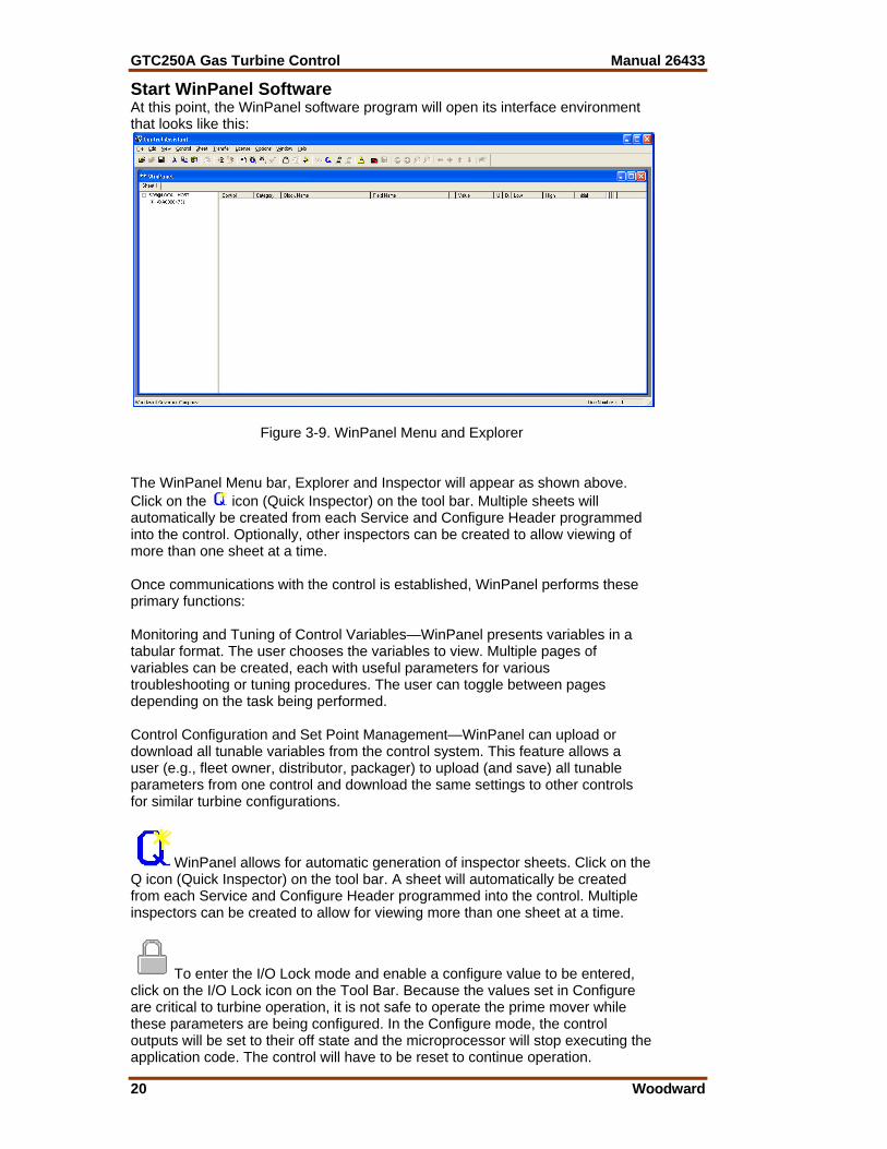
Start WinPanel Software At this point, the WinPanel software program will open its interface environment that looks like this:
Figure 3-9. WinPanel Menu and Explorer The WinPanel Menu bar, Explorer and Inspector will appear as shown above. Click on the icon (Quick Inspector) on the tool bar. Multiple sheets will automatically be created from each Service and Configure Header programmed into the control. Optionally, other inspectors can be created to allow viewing of more than one sheet at a time. Once communications with the control is established, WinPanel performs these primary functions: Monitoring and Tuning of Control Variables—WinPanel presents variables in a tabular format. The user chooses the variables to view. Multiple pages of variables can be created, each with useful parameters for various troubleshooting or tuning procedures. The user can toggle between pages depending on the task being performed. Control Configuration and Set Point Management—WinPanel can upload or download all tunable variables from the control system. This feature allows a user (e.g., fleet owner, distributor, packager) to upload (and save) all tunable parameters from one control and download the same settings to other controls for similar turbine configurations.
WinPanel allows for automatic generation of inspector sheets. Click on the Q icon (Quick Inspector) on the tool bar. A sheet will automatically be created from each Service and Configure Header programmed into the control. Multiple inspectors can be created to allow for viewing more than one sheet at a time.
To enter the I/O Lock mode and enable a configure value to be entered, click on the I/O Lock icon on the Tool Bar. Because the values set in Configure are critical to turbine operation, it is not safe to operate the prime mover while these parameters are being configured. In the Configure mode, the control outputs will be set to their off state and the microprocessor will stop executing the application code. The control will have to be reset to continue operation.

Manual 26433 GTC250A Gas Turbine Control
Woodward 21
The Reset icon allows the microprocessor to store the configure parameters, to return the outputs to their active state, and to resume executing the application software.
When the tuning or setting of parameters is complete, the values must be saved in the control’s non-volatile memory. Go to the Tool Bar and click the PROM icon for Save Values. The values will be saved in non-volatile memory and will be unaffected by loss of power to the control.
To save the configuration to a file in the external computer for backup or download later into another control, select the Save Application Settings icon. All the tunable values presently set in the control will be saved to a file and can be loaded into this control to reprogram it to the saved values or into another control at a later time.
If an application configuration has been previously saved to a *.TC file, the saved set of parameters can be loaded into the control as a group by selecting the Load Application Settings icon.
Configure Menu Descriptions The GTC250A has multiple Configure and Service menus to simplify and protect control settings and their adjustments. All menus appear as pages (or sheets), are arranged alphabetically, and can be located by using the inspector’s arrow buttons located above the pages to scroll to the desired menu. The program’s Configure menu items are protected when the control is in operation and cannot be changed. Before configuration values can be changed, the control must be in its I/O Lock mode. Service menus are not protected and can be modified at any time. To enter the I/O Lock mode and enable configure changes, click on the I/O Lock icon on the Tool Bar. Because the values set in Configure are critical to turbine operation, it is not safe to operate the prime mover while these parameters are being configured. In the I/O Lock mode the control outputs will be set to their off state and the microprocessor will stop executing the application code. Once the configuration changes have been completed, save the values to the control, exit the WWI program, and then Power Cycle the GTC control. This will allow the unit to re-initialize the configured parameters and resume executing the application software.
GTC250A Gas Turbine Control Manual 26433
22 Woodward
Chapter 4. Configuration and Service Setup
Procedures
Introduction This chapter contains information on control configurations, setting adjustments, and the use of Woodward’s WinPanel software tool. Because of the variety of installations, system and component tolerances, the GTC250A must be tuned and configured for each system to obtain optimum performance.
An improperly calibrated control could cause an overspeed or other damage to the prime mover. To prevent possible serious injury from an over speeding prime mover, read this entire procedure before starting the prime mover.
The worksheet in the Appendices of this manual should be used to select the values used in the tunable blocks of the GAP™ program for the GTC250A application. On the lines provided, enter the values used for your control. Once the worksheet is completed, connect the control with the WWII tool as described in the previous section. Click on the Q in the tool bar to execute a routine that will automatically generate an inspector file for all of the configuration and service fields. Using the worksheet, tune each field to the value you require for your application. Use a separate worksheet for each control when more than one control is used at each site. Note that as a user gets more familiar with the system, you can modify/customize your own inspector files to best fit your needs. This should be done at initial installation to establish the correct turbine package configuration details for correct operation of the fuel control. The turbine must be shut down (in a non-running state) during control set-up to tune or adjust any of the parameters on the Configuration sheets. This is not required to adjust or tune any parameters in the Service sheets.
Users that plan to do GAP programming of there own in the Second-Ring (Master) GAP may find that using monitor GAP (with the control or in simulation) is a more convenient way to configure the control. To do this, utilize the CONFIGURE I/O sheets in the GAP and change the default tunables to the desired value for your system.
Manual 26433 GTC250A Gas Turbine Control
Woodward 23
Tunable Upload/Download Function The TUNABLE UPLOAD & DOWNLOAD functionality is used for downloading or uploading tunables into or out of the control. The tunables may be downloaded from the control to a PC anytime, however the turbine must be shutdown while using the TUNABLE UPLOAD FUNCTION mode.
Entering into I/O Lock mode while the turbine is running will cause an automatic shutdown of the turbine with resulting process stoppage. Do not enter the I/O Lock to upload tunables into the control while the turbine is running.
From WW, go to the Explorer Window and ‘right-mouse’ click on the control (top level). A pull-down menu will appear and the App Settings selection will allow you to Save to File or Load from File. • SAVE = Download the tunables in the control to a file on the user PC • LOAD = Upload tunable settings from a user PC into the control Loading tunables into the control will cause the unit to Lock the I/O and shutdown the turbine. A complete list of tunables can be found in Appendix B.
It is highly recommended that the user keep a current tunable list file available at site. This will make the configuration and setup of a spare unit very simple.
Start Modes This control contains options for start control, which is the initial control mode for the fuel. These options are intended to provide a consistent acceleration of the turbine, from turbine ‘lite-off’ up to closed loop GG speed control. Once the fuel control has reached GG control, the start mode demand signal is ramped out of the way (to 100%). The default option is to have the unit transition from Start Ramp to GG Derivative Control (Accel schedule) up to GG Speed control. This allows for the most aggressive ramp-up times of the turbine. For less aggressive ramp-ups, the start ramp rate can be reduced, or the EGT Temp controlled start ramp option can be enabled. Once the Start Ramp Enabled discrete input contact is closed (TRUE), the fuel control will initiate a start. This contact is NOT a latched input, meaning that it must be held TRUE to activate fuel (hold closed versus momentary). If this signal is lost or drops out, the fuel control chops fuel demand to the MIN Fuel Demand position. To achieve successful turbine ‘lite-off’, the unit must have been set up for either a Mechanical Lite-off or an Electrical Lite-off.
For information on setting correct Fuel Flow for lite-off, see the Troubleshooting section.
Mechanical Lite-off = Minimum Valve position mechanically set to yield correct lite-off fuel flow. If this is used configure the MIN_FUEL position to Zero (0.0).
GTC250A Gas Turbine Control Manual 26433
24 Woodward
Electrical Lite-off = Minimum Valve position is set in software (MIN_FUEL) to yield correct valve demand position to yield lite-off fuel flow. If this is used then mechanically the valve should have the min stop set to zero degrees. Start Ramp Control Start The initial increase of fuel valve position is accomplished by a ramp of the Start Ramp from the initial MIN_FUEL position to a point at which a speed loop takes over control of the fuel valve demand. The ramp will increase at the default rate, which is configurable. The start ramp provides a user-defined increase in fuel valve demand and a corresponding acceleration of the turbine until another input of the LSS takes control. If the rate of increase of the ramp becomes too high, the GG Derivative control will take over control of fuel demand. GG Derivative Control Start This is the default start mode programmed for accelerating the turbine from lite-off to speed control. This mode provides a PID control to raise the GG speed at a defined acceleration rate of the GG speed signal. The default rate for this is 50 rpm/s. This control loop steadily increases fuel demand until a point at which a speed loop takes over control. The advantage of this mode is that it is closed loop around a parameter, while the start ramp mode simply opens the fuel valve with no feedback on what is happening. The start ramp default rate (tunable) should be set to be high enough to just stay ahead (greater than) the demand from this PID. The CDP versus Fuel Flow curve limits the Accel PID from over-demanding fuel if the turbine does not accelerate. EGT Temp Ramp Control Start After the initial increase of fuel valve position is accomplished by the start ramp, the EGT PID can be used to bring the unit up to a point at which a speed loop takes over control of the fuel valve demand (usually GG Speed control). The temp ramp contains two user defined setpoints and a ramp rate (in °F/s). The temp ramp starts at the Lower temp setpoint until ‘Lite-off’ is detected. The ramp then ramps up to the High temp setpoint at the user defined rate. This option is useful if a unit is experiencing overtemps during start-ups or the user desires to avoid high temps at sub-idle conditions. If the rate of increase of the ramp becomes too high, the GG Derivative control takes over control of fuel demand.
Alarm Sequence When the fuel control detects an alarm condition, it activates a summary alarm relay output and sends information about the specific cause of the alarm out through the Modbus block. The customer can also go into Service mode and view a numeric alarm value that corresponds to the numbered alarms found in the Appendices of this manual. A reset will clear the alarm if the condition that initiated it no longer exists.

Manual 26433 GTC250A Gas Turbine Control
Woodward 25
Shutdown Sequence When a shutdown occurs, either a fuel control initiated event or the discrete contact shutdown input, all of the actuator signals go to zero and the turbine shuts down. The fuel control will activate a summary shutdown relay output and also send information as to the specific cause of the shutdown out through the Modbus block. The customer can also go into Service mode and view a numeric shutdown value that corresponds to the numbered shutdowns found in the Appendices of this manual. A reset will only clear the shutdown if the condition that initiated it no longer exists AND the GG speed has dropped below the user defined speed setpoint.
Setup of the CDP/Fuel Limiter Curve The GTC250A requires that the user configure a fuel limiter curve based on the compressor discharge pressure of the turbine. The CDP/Fuel Schedule biases on CDP (as the X value) as scaled by the user. The output of the curves block (Y value) limits the LSS bus in scale of 0-100% (that is, if output is 50 for a given input, then fuel flow will not be able to increase above 50%). There are separate curves for gas and liquid fuel—if the turbine is a single fuel, unit then the unused fuel curve should have all Y values set to 100%. To calculate the correct X and Y values for this curve, one of the following methods should be used. • Turbine OEMs typically define a curve of Compressor Discharge Pressure
vs. Fuel (in BTU/hr) in the control or installation manuals for the turbine. The user should get the heating value of the fuel used at their installation site and translate this curve into a CDP vs. Fuel Flow curve. The user should then plot their fuel valve flow output (in pph) versus demanded position (%) and create an appropriate CDP vs Fuel Valve demand curve. Further information of the creation of this curve can be found in the Troubleshooting section.
• The user could record data from their unit while it is currently running and generate a CDP vs Fuel Valve demand curve. The Appendices of this manual contain a sheet to assist in this effort.
NOX Water Injection Setup The control has the capability to control the turbine emissions through the modulation of a NOx control valve. This logic provides a 4–20 mA output that is designed to be the demand signal to a driver for positioning of a water injection valve. The algorithm for calculating the water demand signal is basically a ratio of fuel to water. A tunable curve schedule block that outputs the fuel flow (in pph) based on fuel valve demand position must be set up first. The output of this block yields the calculated fuel flow, and is used to determine the correct water flow demand. The output side (Y-values) of this curve block is all tunable values to be configured by the user. There are separate schedule curves for gas and liquid fuel. There are also ‘ratio multipliers’ and raise and lower inputs to the ramp to adjust the NOx demand from the base ratio schedule.

GTC250A Gas Turbine Control Manual 26433
26 Woodward
NOX Steam Injection Setup The control has the capability to control the turbine emissions through the modulation of a NOx control valve. This logic provides a 4–20 mA output that is designed to be the demand signal to a driver for positioning of a steam injection valve. The logic for calculating the steam demand is driven by the mathematical product of a base steam curve (driven by the fuel flow curve), a gain multiplier for each point on this base curve, and an overall gain multiplier. This value is then low-signal selected (LSS) with a curve driven by a CDP input. The CDP curve is usually used as the upper limiter of steam demand, but can be used as the main schedule driver if desired. This value is used as the demand input into a deadband control block, and a NOx steam flow signal is used as the active feedback signal to the deadband controller. This block then drives a ramp block that ultimately positions the valve demand output. There are also raise and lower inputs to the ramp to adjust the NOx demand from the base ratio schedule. The schedule curves for calculating the gas and liquid fuel flow as a function of fuel valve position are the same curves as the ones set up for the NOx water setup.
Power Augmentation Steam Injection Setup The control has the capability to provide the demand signal for a power augmentation steam injection valve. Some installed turbine designs incorporate an optional system that boosts the overall power output of the gas generator system. This logic provides a 4–20 mA output that is designed to be the demand signal to a driver for positioning of a steam injection valve for this purpose. There are options for steam flow schedules and a raise and lower ramp to adjust the demand to the desired levels. This value is used as the demand input into a deadband control block, and a steam flow signal is used as the active feedback signal to the deadband controller. This block then drives a ramp block that ultimately positions the steam valve demand output.

Manual 26433 GTC250A Gas Turbine Control
Woodward 27
Chapter 5. Troubleshooting
Dynamic Response Problems PID Controller Tuning The majority of problems associated with the control of the turbine can be attributed to poor tuning of the PID control loops. These problems include overspeeding, overtemping, and flaming out as well as many others. For example, if the turbine control is hunting, the loop that is currently controlling the fuel valve is most likely incorrectly tuned and could cause sufficient overshoot to overspeed or overtemp the turbine. Some general tuning guidelines are outlined below.
Tuning of PID loops should only be performed by qualified personnel that have a good understanding how the control should be performing. Improper tuning can result in overspeed or overtemp conditions, which could cause damage to the turbine or possible injury or death to personnel.
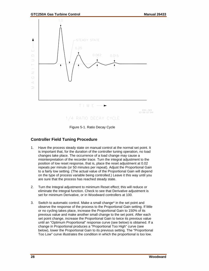
The quality of regulation obtained from an automatic control system depends upon the adjustments that are made to the various controller modes. Best results are obtained when the adjustment (tuning) is done systematically. Prior training and experience in controller tuning are desirable for effective application of this procedure. This procedure will lead to controller settings, which, after a load change, will provide: • Process control without sustained cycling • Process recovery in a minimum time Controller settings derived for given operating conditions are valid over a narrow range of load change. The settings made for one operating set of conditions may result in excessive cycling or highly damped response at some other operating condition. This procedure should be applied under the most difficult operating conditions to assure conservative settings over the normal operating range. There are several methods of controller tuning in use. The following procedure presents one which will be easy to use, and at the same time minimize process upset. This method is one of systematic trial and error. The method given is based upon the 1/4-ratio decay cycle. The peak of each cycle is 1/4 of the preceding one. The objective is to produce a trace as shown in Figure 5-1. It is good practice to keep the average of the set point changes near the normal set point of the process to avoid excessive departure from normal operating level. After each set point change, allow sufficient time to observe the effect of the last adjustment. It is wise to wait until approximately 90% of the change has been completed.
GTC250A Gas Turbine Control Manual 26433
28 Woodward
Figure 5-1. Ratio Decay Cycle Controller Field Tuning Procedure 1. Have the process steady state on manual control at the normal set point. It
is important that, for the duration of the controller tuning operation, no load changes take place. The occurrence of a load change may cause a misinterpretation of the recorder trace. Turn the integral adjustment to the position of low reset response, that is, place the reset adjustment at 0.02 repeats per minute (or 50 minutes per repeat). Adjust the Proportional Gain to a fairly low setting. (The actual value of the Proportional Gain will depend on the type of process variable being controlled.) Leave it this way until you are sure that the process has reached steady state.
2. Turn the Integral adjustment to minimum Reset effect; this will reduce or
eliminate the Integral function. Check to see that Derivative adjustment is set for minimum Derivative, or in Woodward controllers at 100.
3. Switch to automatic control. Make a small change* in the set point and
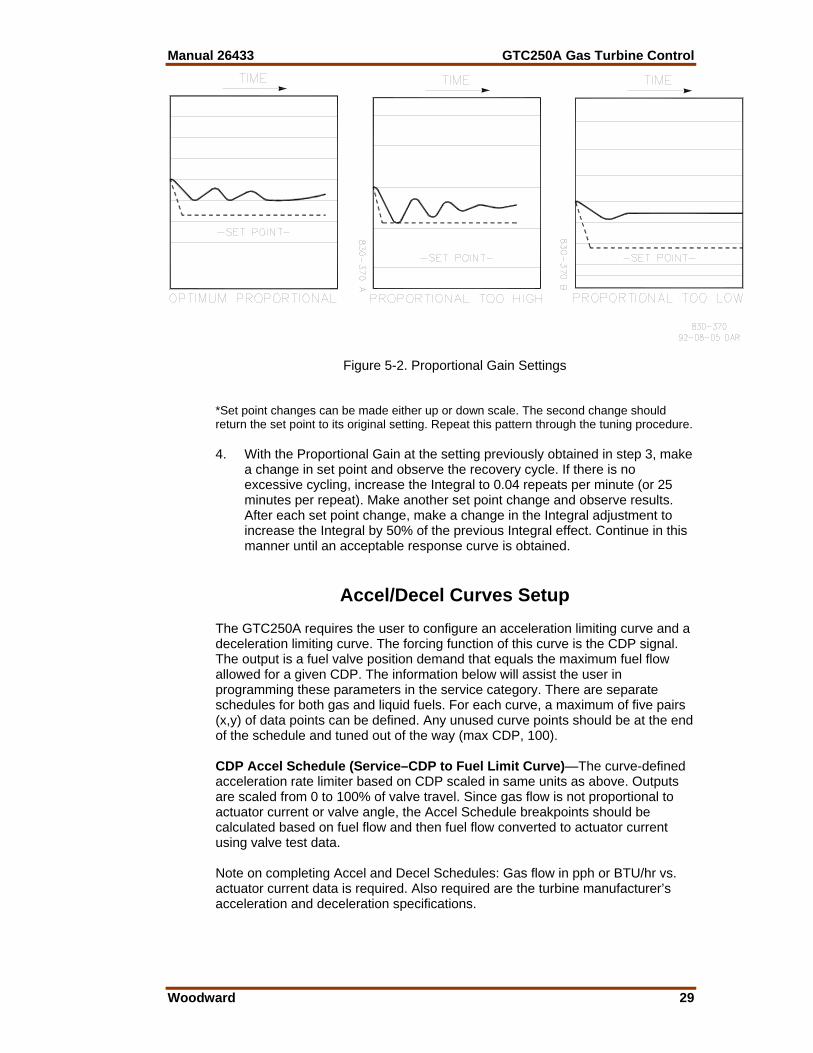
observe the response of the process to the Proportional Gain setting. If little or no cycling takes place, increase the Proportional Gain to 150% of its previous value and make another small change to the set point. After each set point change, increase the Proportional Gain to twice its previous value until an "Optimum Proportional" response curve (see below) is obtained. If a change in Proportional produces a "Proportional Too High" curve (see below), lower the Proportional Gain to its previous setting. The "Proportional Too Low" curve illustrates the condition in which the proportional is too low.
Manual 26433 GTC250A Gas Turbine Control
Woodward 29
Figure 5-2. Proportional Gain Settings
*Set point changes can be made either up or down scale. The second change should return the set point to its original setting. Repeat this pattern through the tuning procedure. 4. With the Proportional Gain at the setting previously obtained in step 3, make
a change in set point and observe the recovery cycle. If there is no excessive cycling, increase the Integral to 0.04 repeats per minute (or 25 minutes per repeat). Make another set point change and observe results. After each set point change, make a change in the Integral adjustment to increase the Integral by 50% of the previous Integral effect. Continue in this manner until an acceptable response curve is obtained.
Accel/Decel Curves Setup The GTC250A requires the user to configure an acceleration limiting curve and a deceleration limiting curve. The forcing function of this curve is the CDP signal. The output is a fuel valve position demand that equals the maximum fuel flow allowed for a given CDP. The information below will assist the user in programming these parameters in the service category. There are separate schedules for both gas and liquid fuels. For each curve, a maximum of five pairs (x,y) of data points can be defined. Any unused curve points should be at the end of the schedule and tuned out of the way (max CDP, 100). CDP Accel Schedule (Service–CDP to Fuel Limit Curve)—The curve-defined acceleration rate limiter based on CDP scaled in same units as above. Outputs are scaled from 0 to 100% of valve travel. Since gas flow is not proportional to actuator current or valve angle, the Accel Schedule breakpoints should be calculated based on fuel flow and then fuel flow converted to actuator current using valve test data. Note on completing Accel and Decel Schedules: Gas flow in pph or BTU/hr vs. actuator current data is required. Also required are the turbine manufacturer’s acceleration and deceleration specifications.
GTC250A Gas Turbine Control Manual 26433
30 Woodward
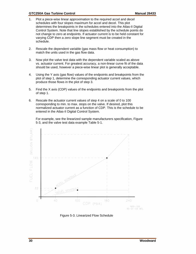
1. Plot a piece-wise linear approximation to the required accel and decel schedules with four slopes maximum for accel and decel. This plot determines the breakpoints in the schedules entered into the Atlas-II Digital Control System. Note that line slopes established by the schedule points do not change to zero at endpoints. If actuator current is to be held constant for varying CDP then a zero slope line segment must be created in the schedule.
2. Rescale the dependent variable (gas mass flow or heat consumption) to
match the units used in the gas flow data. 3. Now plot the valve test data with the dependent variable scaled as above
vs. actuator current. For greatest accuracy, a non-linear curve fit of the data should be used, however a piece-wise linear plot is generally acceptable.
4. Using the Y axis (gas flow) values of the endpoints and breakpoints from the
plot of step 1, determine the corresponding actuator current values, which produce those flows in the plot of step 3.
5. Find the X axis (CDP) values of the endpoints and breakpoints from the plot
of step 1. 6. Rescale the actuator current values of step 4 on a scale of 0 to 100
corresponding to min. to max. stops on the valve. If desired, plot this normalized actuator current as a function of CDP. This is the schedule to be entered in the Atlas-II Digital Control System.
For example, see the linearized sample manufacturers specification, Figure
5-3, and the valve test data example Table 5-1.
Figure 5-3. Linearized Flow Schedule
Manual 26433 GTC250A Gas Turbine Control
Woodward 31
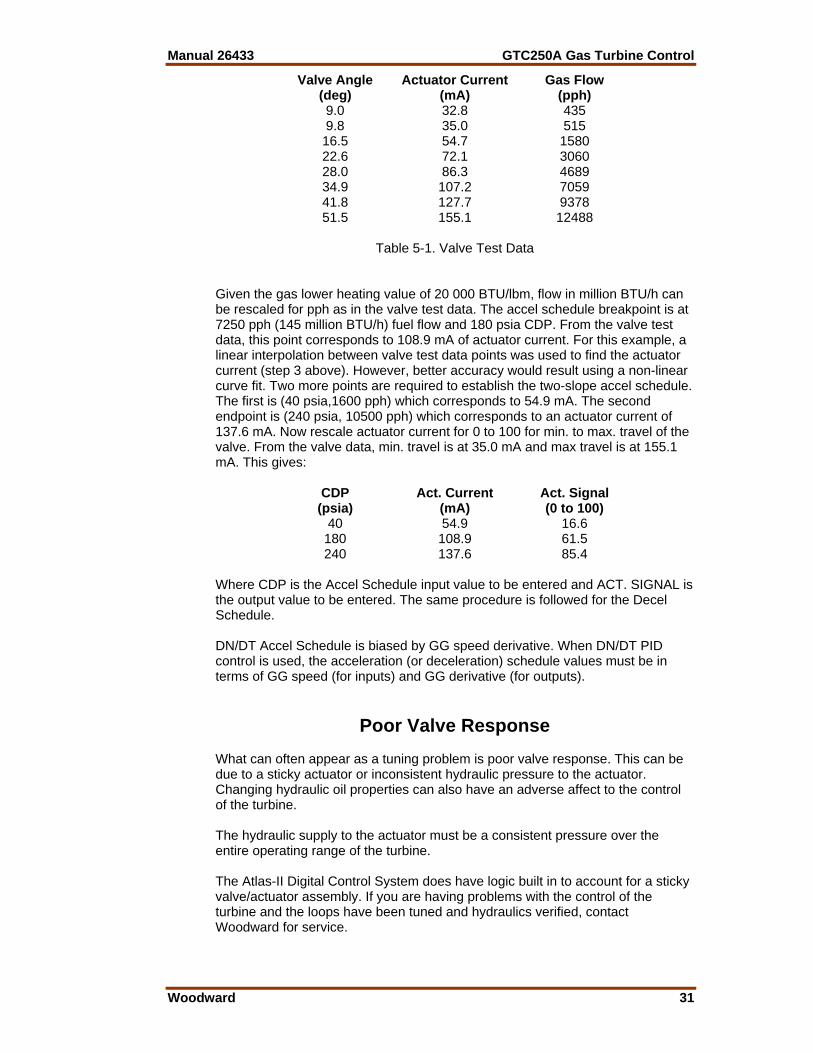
Valve Angle Actuator Current Gas Flow (deg) (mA) (pph) 9.0 32.8 435 9.8 35.0 515 16.5 54.7 1580 22.6 72.1 3060 28.0 86.3 4689 34.9 107.2 7059 41.8 127.7 9378 51.5 155.1 12488
Table 5-1. Valve Test Data Given the gas lower heating value of 20 000 BTU/lbm, flow in million BTU/h can be rescaled for pph as in the valve test data. The accel schedule breakpoint is at 7250 pph (145 million BTU/h) fuel flow and 180 psia CDP. From the valve test data, this point corresponds to 108.9 mA of actuator current. For this example, a linear interpolation between valve test data points was used to find the actuator current (step 3 above). However, better accuracy would result using a non-linear curve fit. Two more points are required to establish the two-slope accel schedule. The first is (40 psia,1600 pph) which corresponds to 54.9 mA. The second endpoint is (240 psia, 10500 pph) which corresponds to an actuator current of 137.6 mA. Now rescale actuator current for 0 to 100 for min. to max. travel of the valve. From the valve data, min. travel is at 35.0 mA and max travel is at 155.1 mA. This gives: CDP Act. Current Act. Signal (psia) (mA) (0 to 100) 40 54.9 16.6 180 108.9 61.5 240 137.6 85.4 Where CDP is the Accel Schedule input value to be entered and ACT. SIGNAL is the output value to be entered. The same procedure is followed for the Decel Schedule. DN/DT Accel Schedule is biased by GG speed derivative. When DN/DT PID control is used, the acceleration (or deceleration) schedule values must be in terms of GG speed (for inputs) and GG derivative (for outputs).
Poor Valve Response What can often appear as a tuning problem is poor valve response. This can be due to a sticky actuator or inconsistent hydraulic pressure to the actuator. Changing hydraulic oil properties can also have an adverse affect to the control of the turbine. The hydraulic supply to the actuator must be a consistent pressure over the entire operating range of the turbine. The Atlas-II Digital Control System does have logic built in to account for a sticky valve/actuator assembly. If you are having problems with the control of the turbine and the loops have been tuned and hydraulics verified, contact Woodward for service.
GTC250A Gas Turbine Control Manual 26433
32 Woodward
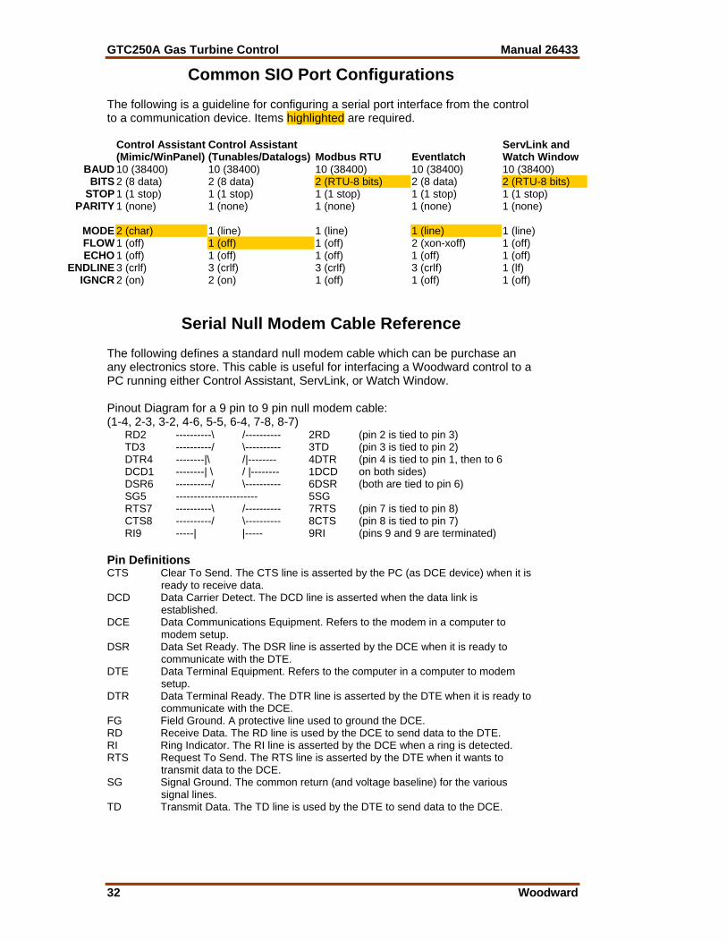
Common SIO Port Configurations The following is a guideline for configuring a serial port interface from the control to a communication device. Items highlighted are required.
Control Assistant (Mimic/WinPanel)
Control Assistant (Tunables/Datalogs) Modbus RTU Eventlatch
ServLink and Watch Window
BAUD 10 (38400) 10 (38400) 10 (38400) 10 (38400) 10 (38400) BITS 2 (8 data) 2 (8 data) 2 (RTU-8 bits) 2 (8 data) 2 (RTU-8 bits)
STOP 1 (1 stop) 1 (1 stop) 1 (1 stop) 1 (1 stop) 1 (1 stop) PARITY 1 (none) 1 (none) 1 (none) 1 (none) 1 (none)
MODE 2 (char) 1 (line) 1 (line) 1 (line) 1 (line) FLOW 1 (off) 1 (off) 1 (off) 2 (xon-xoff) 1 (off) ECHO 1 (off) 1 (off) 1 (off) 1 (off) 1 (off)
ENDLINE 3 (crlf) 3 (crlf) 3 (crlf) 3 (crlf) 1 (lf) IGNCR 2 (on) 2 (on) 1 (off) 1 (off) 1 (off)
Serial Null Modem Cable Reference The following defines a standard null modem cable which can be purchase an any electronics store. This cable is useful for interfacing a Woodward control to a PC running either Control Assistant, ServLink, or Watch Window. Pinout Diagram for a 9 pin to 9 pin null modem cable: (1-4, 2-3, 3-2, 4-6, 5-5, 6-4, 7-8, 8-7)
RD2 ----------\ /---------- 2RD (pin 2 is tied to pin 3) TD3 ----------/ \---------- 3TD (pin 3 is tied to pin 2) DTR4 --------|\ /|-------- 4DTR (pin 4 is tied to pin 1, then to 6 DCD1 --------| \ / |-------- 1DCD on both sides) DSR6 ----------/ \---------- 6DSR (both are tied to pin 6) SG5 ----------------------- 5SG RTS7 ----------\ /---------- 7RTS (pin 7 is tied to pin 8) CTS8 ----------/ \---------- 8CTS (pin 8 is tied to pin 7) RI9 -----| |----- 9RI (pins 9 and 9 are terminated)
Pin Definitions CTS Clear To Send. The CTS line is asserted by the PC (as DCE device) when it is
ready to receive data. DCD Data Carrier Detect. The DCD line is asserted when the data link is
established. DCE Data Communications Equipment. Refers to the modem in a computer to
modem setup. DSR Data Set Ready. The DSR line is asserted by the DCE when it is ready to
communicate with the DTE. DTE Data Terminal Equipment. Refers to the computer in a computer to modem
setup. DTR Data Terminal Ready. The DTR line is asserted by the DTE when it is ready to
communicate with the DCE. FG Field Ground. A protective line used to ground the DCE. RD Receive Data. The RD line is used by the DCE to send data to the DTE. RI Ring Indicator. The RI line is asserted by the DCE when a ring is detected. RTS Request To Send. The RTS line is asserted by the DTE when it wants to
transmit data to the DCE. SG Signal Ground. The common return (and voltage baseline) for the various
signal lines. TD Transmit Data. The TD line is used by the DTE to send data to the DCE.

Manual 26433 GTC250A Gas Turbine Control
Woodward 33
Chapter 6. Service Options
Product Service Options If you are experiencing problems with the installation, or unsatisfactory performance of a Woodward product, the following options are available: • Consult the troubleshooting guide in the manual. • Contact the manufacturer or packager of your system. • Contact the Woodward Full Service Distributor serving your area. • Contact Woodward technical assistance (see “How to Contact Woodward”
later in this chapter) and discuss your problem. In many cases, your problem can be resolved over the phone. If not, you can select which course of action to pursue based on the available services listed in this chapter.
OEM and Packager Support: Many Woodward controls and control devices are installed into the equipment system and programmed by an Original Equipment Manufacturer (OEM) or Equipment Packager at their factory. In some cases, the programming is password-protected by the OEM or packager, and they are the best source for product service and support. Warranty service for Woodward products shipped with an equipment system should also be handled through the OEM or Packager. Please review your equipment system documentation for details. Woodward Business Partner Support: Woodward works with and supports a global network of independent business partners whose mission is to serve the users of Woodward controls, as described here:
• A Full Service Distributor has the primary responsibility for sales, service, system integration solutions, technical desk support, and aftermarket marketing of standard Woodward products within a specific geographic area and market segment.
• An Authorized Independent Service Facility (AISF) provides authorized service that includes repairs, repair parts, and warranty service on Woodward's behalf. Service (not new unit sales) is an AISF's primary mission.
• A Recognized Engine Retrofitter (RER) is an independent company that does retrofits and upgrades on reciprocating gas engines and dual-fuel conversions, and can provide the full line of Woodward systems and components for the retrofits and overhauls, emission compliance upgrades, long term service contracts, emergency repairs, etc.
• A Recognized Turbine Retrofitter (RTR) is an independent company that does both steam and gas turbine control retrofits and upgrades globally, and can provide the full line of Woodward systems and components for the retrofits and overhauls, long term service contracts, emergency repairs, etc.
A current list of Woodward Business Partners is available at www.woodward.com/support.

GTC250A Gas Turbine Control Manual 26433
34 Woodward
Woodward Factory Servicing Options The following factory options for servicing Woodward products are available through your local Full-Service Distributor or the OEM or Packager of the equipment system, based on the standard Woodward Product and Service Warranty (5-01-1205) that is in effect at the time the product is originally shipped from Woodward or a service is performed: • Replacement/Exchange (24-hour service) • Flat Rate Repair • Flat Rate Remanufacture Replacement/Exchange: Replacement/Exchange is a premium program designed for the user who is in need of immediate service. It allows you to request and receive a like-new replacement unit in minimum time (usually within 24 hours of the request), providing a suitable unit is available at the time of the request, thereby minimizing costly downtime. This is a flat-rate program and includes the full standard Woodward product warranty (Woodward Product and Service Warranty 5-01-1205). This option allows you to call your Full-Service Distributor in the event of an unexpected outage, or in advance of a scheduled outage, to request a replacement control unit. If the unit is available at the time of the call, it can usually be shipped out within 24 hours. You replace your field control unit with the like-new replacement and return the field unit to the Full-Service Distributor. Charges for the Replacement/Exchange service are based on a flat rate plus shipping expenses. You are invoiced the flat rate replacement/exchange charge plus a core charge at the time the replacement unit is shipped. If the core (field unit) is returned within 60 days, a credit for the core charge will be issued. Flat Rate Repair: Flat Rate Repair is available for the majority of standard products in the field. This program offers you repair service for your products with the advantage of knowing in advance what the cost will be. All repair work carries the standard Woodward service warranty (Woodward Product and Service Warranty 5-01-1205) on replaced parts and labor. Flat Rate Remanufacture: Flat Rate Remanufacture is very similar to the Flat Rate Repair option with the exception that the unit will be returned to you in “like-new” condition and carry with it the full standard Woodward product warranty (Woodward Product and Service Warranty 5-01-1205). This option is applicable to mechanical products only.

Manual 26433 GTC250A Gas Turbine Control
Woodward 35
Returning Equipment for Repair If a control (or any part of an electronic control) is to be returned for repair, please contact your Full-Service Distributor in advance to obtain Return Authorization and shipping instructions. When shipping the item(s), attach a tag with the following information: • return number; • name and location where the control is installed; • name and phone number of contact person; • complete Woodward part number(s) and serial number(s); • description of the problem; • instructions describing the desired type of repair. Packing a Control Use the following materials when returning a complete control: • protective caps on any connectors; • antistatic protective bags on all electronic modules; • packing materials that will not damage the surface of the unit; • at least 100 mm (4 inches) of tightly packed, industry-approved packing
material; • a packing carton with double walls; • a strong tape around the outside of the carton for increased strength.
To prevent damage to electronic components caused by improper handling, read and observe the precautions in Woodward manual 82715, Guide for Handling and Protection of Electronic Controls, Printed Circuit Boards, and Modules.
Replacement Parts When ordering replacement parts for controls, include the following information: • the part number(s) (XXXX-XXXX) that is on the enclosure nameplate; • the unit serial number, which is also on the nameplate.

GTC250A Gas Turbine Control Manual 26433
36 Woodward
Engineering Services Woodward offers various Engineering Services for our products. For these services, you can contact us by telephone, by email, or through the Woodward website. • Technical Support • Product Training • Field Service Technical Support is available from your equipment system supplier, your local Full-Service Distributor, or from many of Woodward’s worldwide locations, depending upon the product and application. This service can assist you with technical questions or problem solving during the normal business hours of the Woodward location you contact. Emergency assistance is also available during non-business hours by phoning Woodward and stating the urgency of your problem. Product Training is available as standard classes at many of our worldwide locations. We also offer customized classes, which can be tailored to your needs and can be held at one of our locations or at your site. This training, conducted by experienced personnel, will assure that you will be able to maintain system reliability and availability. Field Service engineering on-site support is available, depending on the product and location, from many of our worldwide locations or from one of our Full-Service Distributors. The field engineers are experienced both on Woodward products as well as on much of the non-Woodward equipment with which our products interface. For information on these services, please contact us via telephone, email us, or use our website and reference www.woodward.com/support, and then Customer Support.
How to Contact Woodward For assistance, call one of the following Woodward facilities to obtain the address and phone number of the facility nearest your location where you will be able to get information and service.
Electrical Power Systems Facility --------------- Phone Number Australia ----------- +61 (2) 9758 2322 Brazil ------------- +55 (19) 3708 4800 China ------------ +86 (512) 6762 6727 Germany: Kempen --- +49 (0) 21 52 14 51 Stuttgart ----- +49 (711) 78954-0 India --------------- +91 (129) 4097100 Japan -------------- +81 (43) 213-2191 Korea--------------- +82 (51) 636-7080 Poland -------------- +48 12 618 92 00 United States----- +1 (970) 482-5811
Engine Systems Facility --------------- Phone Number Australia ----------- +61 (2) 9758 2322 Brazil ------------- +55 (19) 3708 4800 China ------------ +86 (512) 6762 6727 Germany: Stuttgart ----- +49 (711) 78954-0 India --------------- +91 (129) 4097100 Japan -------------- +81 (43) 213-2191 Korea--------------- +82 (51) 636-7080 The Netherlands - +31 (23) 5661111 United States----- +1 (970) 482-5811
Turbine Systems Facility --------------- Phone Number Australia ----------- +61 (2) 9758 2322 Brazil ------------- +55 (19) 3708 4800 China ------------ +86 (512) 6762 6727 India --------------- +91 (129) 4097100 Japan -------------- +81 (43) 213-2191 Korea--------------- +82 (51) 636-7080 The Netherlands - +31 (23) 5661111 United States----- +1 (970) 482-5811
You can also contact the Woodward Customer Service Department or consult our worldwide directory on Woodward’s website (www.woodward.com/support) for the name of your nearest Woodward distributor or service facility. For the most current product support and contact information, please refer to the latest version of publication 51337 at www.woodward.com/publications.
Manual 26433 GTC250A Gas Turbine Control
Woodward 37
Technical Assistance If you need to telephone for technical assistance, you will need to provide the following information. Please write it down here before phoning: General Your Name Site Location Phone Number Fax Number Prime Mover Information Engine/Turbine Model Number Manufacturer Number of Cylinders (if applicable) Type of Fuel (gas, gaseous, steam, etc) Rating Application Control/Governor Information Please list all Woodward governors, actuators, and electronic controls in your system: Woodward Part Number and Revision Letter Control Description or Governor Type Serial Number Woodward Part Number and Revision Letter Control Description or Governor Type Serial Number Woodward Part Number and Revision Letter Control Description or Governor Type Serial Number If you have an electronic or programmable control, please have the adjustment setting positions or the menu settings written down and with you at the time of the call.
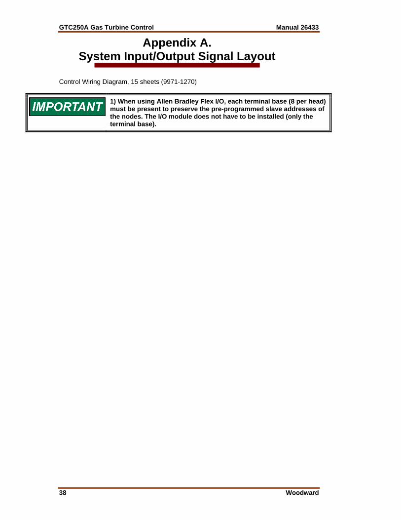
GTC250A Gas Turbine Control Manual 26433
38 Woodward
Appendix A. System Input/Output Signal Layout
Control Wiring Diagram, 15 sheets (9971-1270)
1) When using Allen Bradley Flex I/O, each terminal base (8 per head) must be present to preserve the pre-programmed slave addresses of the nodes. The I/O module does not have to be installed (only the terminal base).
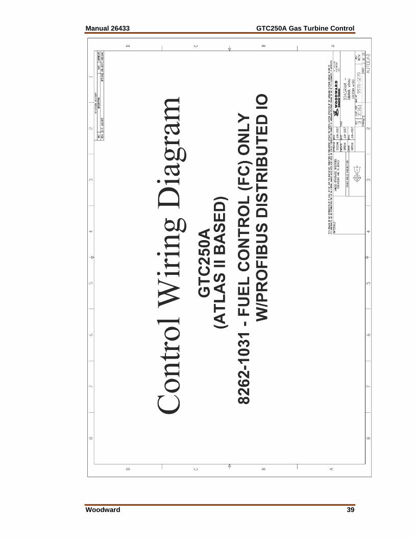
Manual 26433 GTC250A Gas Turbine Control
Woodward 39
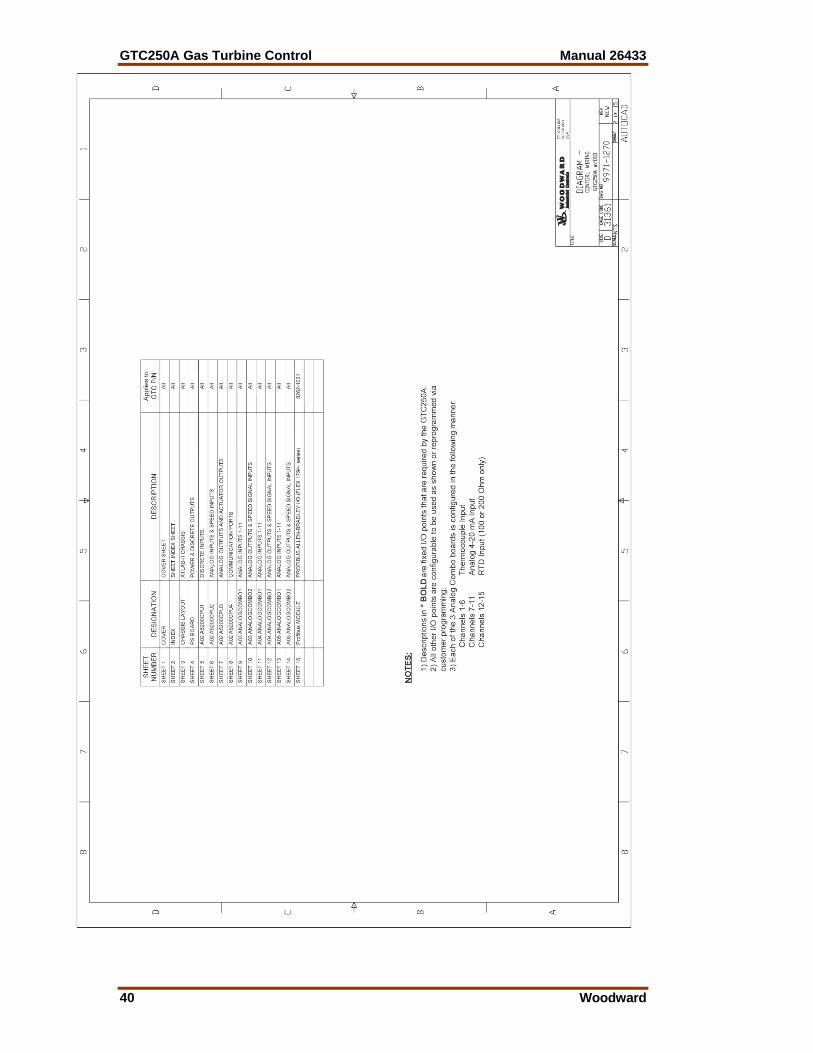
GTC250A Gas Turbine Control Manual 26433
40 Woodward
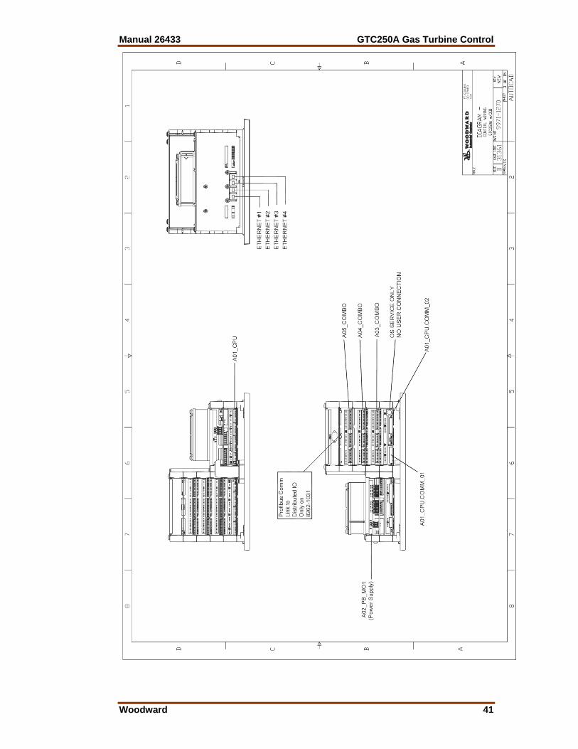
Manual 26433 GTC250A Gas Turbine Control
Woodward 41
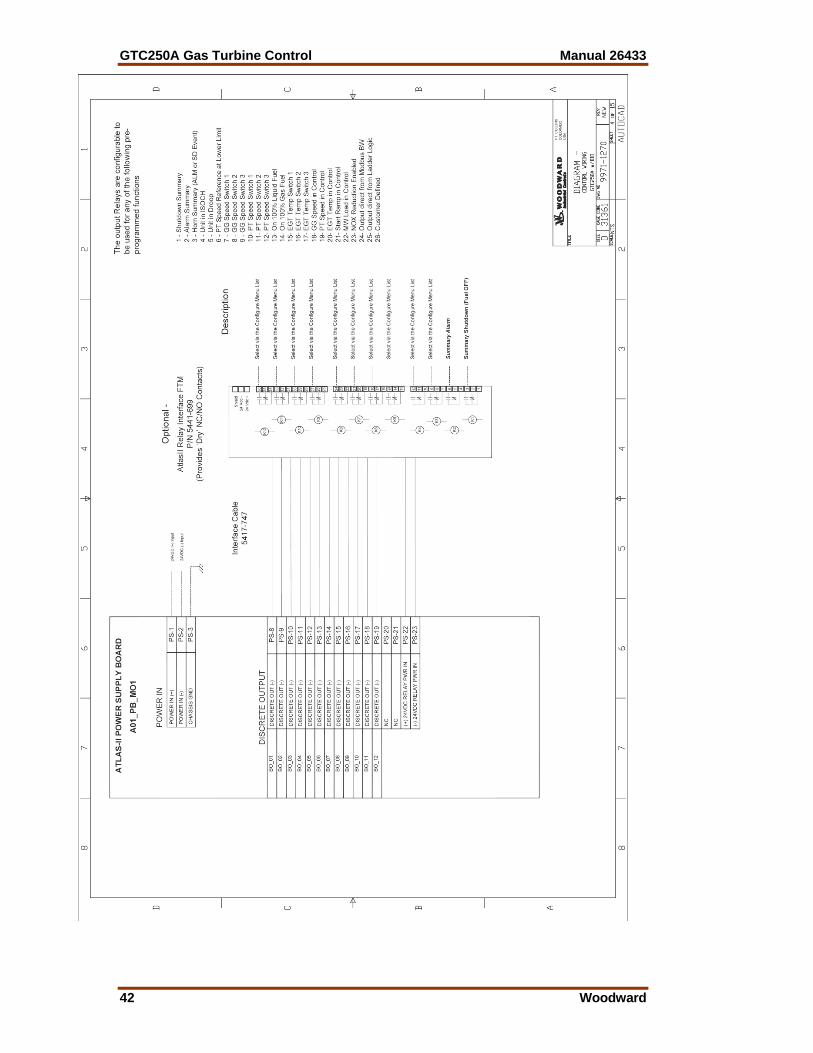
GTC250A Gas Turbine Control Manual 26433
42 Woodward
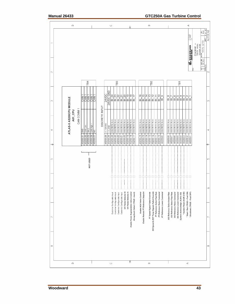
Manual 26433 GTC250A Gas Turbine Control
Woodward 43
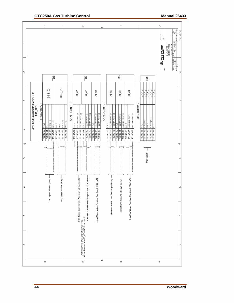
GTC250A Gas Turbine Control Manual 26433
44 Woodward
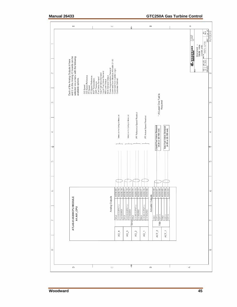
Manual 26433 GTC250A Gas Turbine Control
Woodward 45
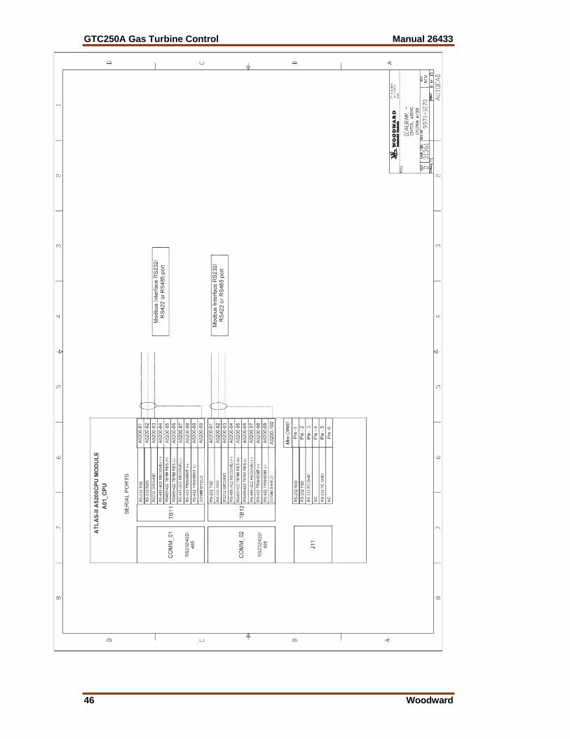
GTC250A Gas Turbine Control Manual 26433
46 Woodward
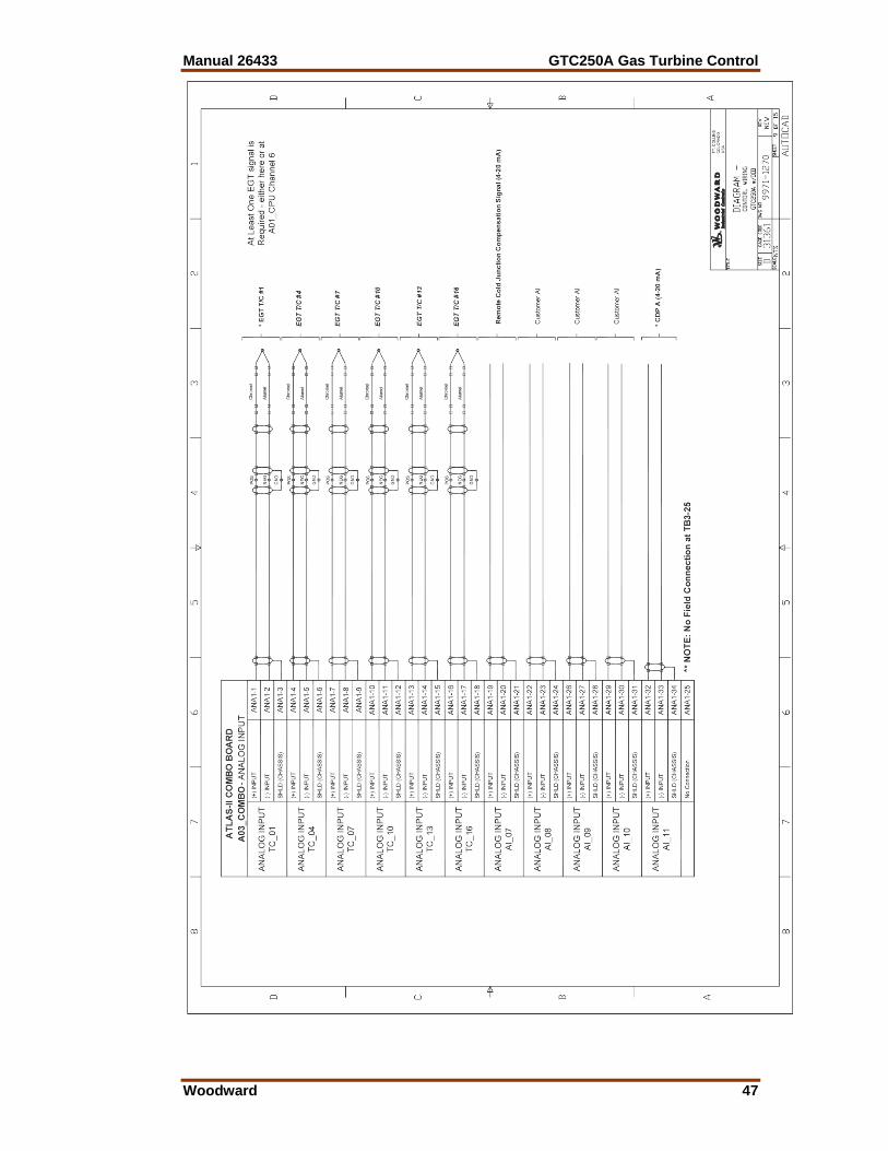
Manual 26433 GTC250A Gas Turbine Control
Woodward 47
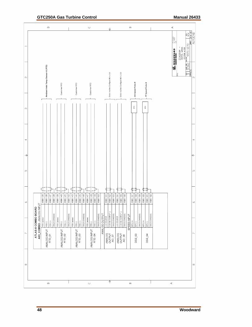
GTC250A Gas Turbine Control Manual 26433
48 Woodward
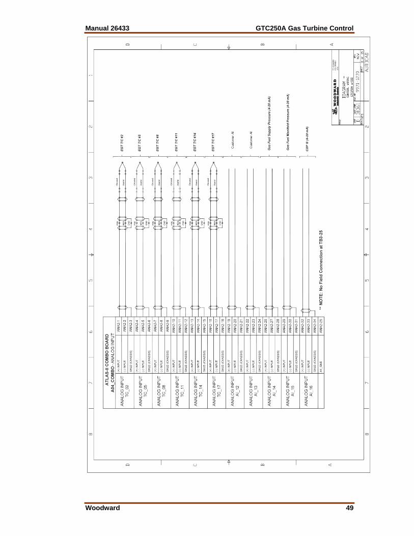
Manual 26433 GTC250A Gas Turbine Control
Woodward 49
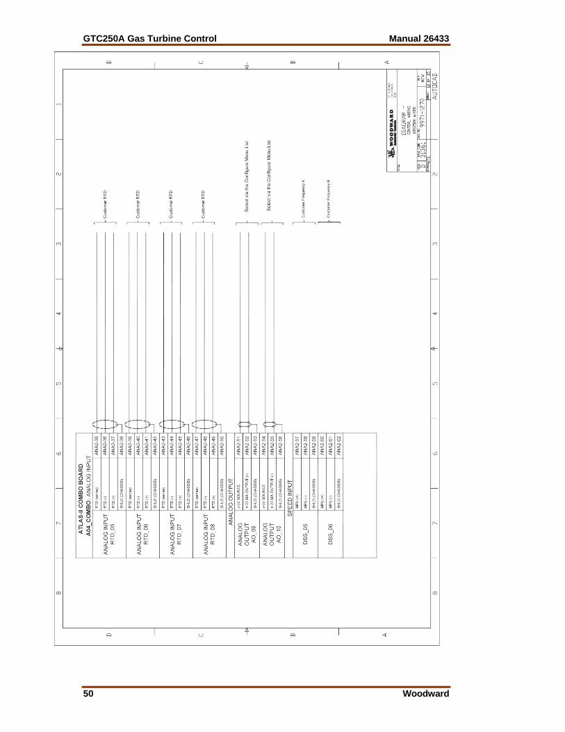
GTC250A Gas Turbine Control Manual 26433
50 Woodward
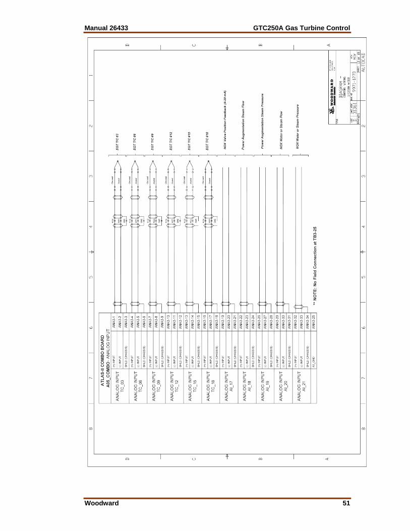
Manual 26433 GTC250A Gas Turbine Control
Woodward 51

GTC250A Gas Turbine Control Manual 26433
52 Woodward
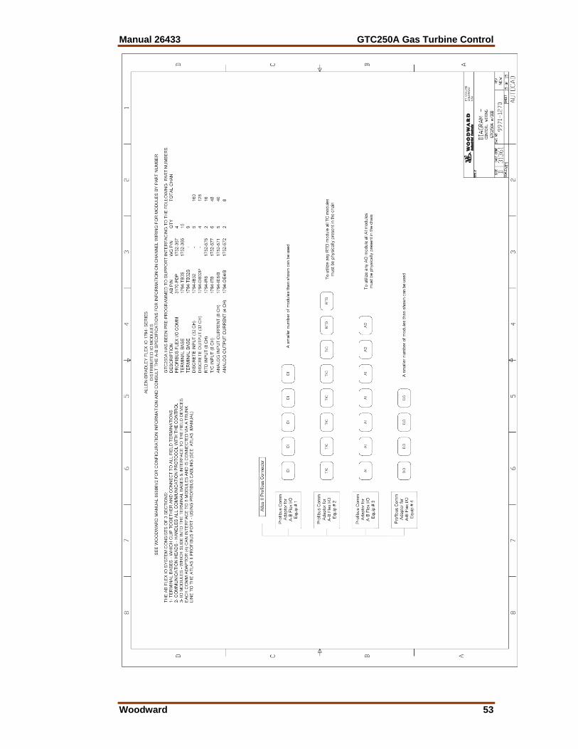
Manual 26433 GTC250A Gas Turbine Control
Woodward 53
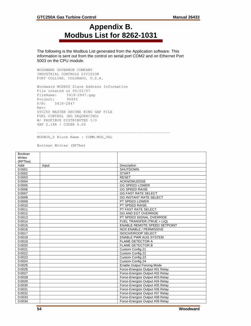
GTC250A Gas Turbine Control Manual 26433
54 Woodward
Appendix B. Modbus List for 8262-1031
The following is the Modbus List generated from the Application software. This information is sent out from the control on serial port COM2 and on Ethernet Port 5003 on the CPU module. WOODWARD GOVERNOR COMPANY INDUSTRIAL CONTROLS DIVISION FORT COLLINS, COLORADO, U.S.A. Woodward MODBUS Slave Address Information File created on 06/22/07 FileName: 5418-2847.gap Project: 90493 P/N: 5418-2847 Rev: GTC250 MASTER SECOND RING GAP FILE FUEL CONTROL (NO SEQUENCING) W/ PROFIBUS DISTRIBUTED I/O GAP 2.18A / CODER 4.04 ------------------------------------------------------------ MODBUS_S Block Name : COMM.MOD_VAL Boolean Writes (RPTbw)
Boolean Writes (RPTbw)
Addr Input Description 0:0001 SHUTDOWN 0:0002 START 0:0003 RESET 0:0004 ACKNOWLEDGE 0:0005 GG SPEED LOWER 0:0006 GG SPEED RAISE 0:0007 GG FAST RATE SELECT 0:0008 GG INSTANT RATE SELECT 0:0009 PT SPEED LOWER 0:0010 PT SPEED RAISE 0:0011 PT FAST RATE SELECT 0:0012 GG AND EGT OVERRIDE 0:0013 PT SPEED SIGNAL OVERRIDE 0:0014 FUEL TRANSFER (TRUE = LIQ) 0:0015 ENABLE REMOTE SPEED SETPOINT 0:0016 NOX ENABLE / PERMISSIVE 0:0017 ISOCH/DROOP SELECT 0:0018 ENABLE PWR AUG SYSTEM 0:0019 FLAME DETECTOR A 0:0020 FLAME DETECTOR B 0:0021 Custom Config 21 0:0022 Custom Config 22 0:0023 Custom Config 23 0:0024 Custom Config 24 0:0025 Enable Output Forcing Mode 0:0026 Force-Energize Output #01 Relay 0:0027 Force-Energize Output #02 Relay 0:0028 Force-Energize Output #03 Relay 0:0029 Force-Energize Output #04 Relay 0:0030 Force-Energize Output #05 Relay 0:0031 Force-Energize Output #06 Relay 0:0032 Force-Energize Output #07 Relay 0:0033 Force-Energize Output #08 Relay 0:0034 Force-Energize Output #09 Relay
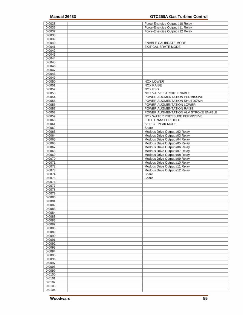
Manual 26433 GTC250A Gas Turbine Control
Woodward 55
0:0035 Force-Energize Output #10 Relay 0:0036 Force-Energize Output #11 Relay 0:0037 Force-Energize Output #12 Relay 0:0038 0:0039 0:0040 ENABLE CALIBRATE MODE 0:0041 EXIT CALIBRATE MODE 0:0042 0:0043 0:0044 0:0045 0:0046 0:0047 0:0048 0:0049 0:0050 NOX LOWER 0:0051 NOX RAISE 0:0052 NOX ESD 0:0053 NOX VALVE STROKE ENABLE 0:0054 POWER AUGMENTATION PERMISSIVE 0:0055 POWER AUGMENTATION SHUTDOWN 0:0056 POWER AUGMENTATION LOWER 0:0057 POWER AUGMENTATION RAISE 0:0058 POWER AUGMENTATION VLV STROKE ENABLE 0:0059 NOX WATER PRESSURE PERMISSIVE 0:0060 FUEL TRANSFER HOLD 0:0061 SELECT PEAK MODE 0:0062 Spare 0:0063 Modbus Drive Output #02 Relay 0:0064 Modbus Drive Output #03 Relay 0:0065 Modbus Drive Output #04 Relay 0:0066 Modbus Drive Output #05 Relay 0:0067 Modbus Drive Output #06 Relay 0:0068 Modbus Drive Output #07 Relay 0:0069 Modbus Drive Output #08 Relay 0:0070 Modbus Drive Output #09 Relay 0:0071 Modbus Drive Output #10 Relay 0:0072 Modbus Drive Output #11 Relay 0:0073 Modbus Drive Output #12 Relay 0:0074 Spare 0:0075 Spare 0:0076 0:0077 0:0078 0:0079 0:0080 0:0081 0:0082 0:0083 0:0084 0:0085 0:0086 0:0087 0:0088 0:0089 0:0090 0:0091 0:0092 0:0093 0:0094 0:0095 0:0096 0:0097 0:0098 0:0099 0:0100 0:0101 0:0102 0:0103 0:0104
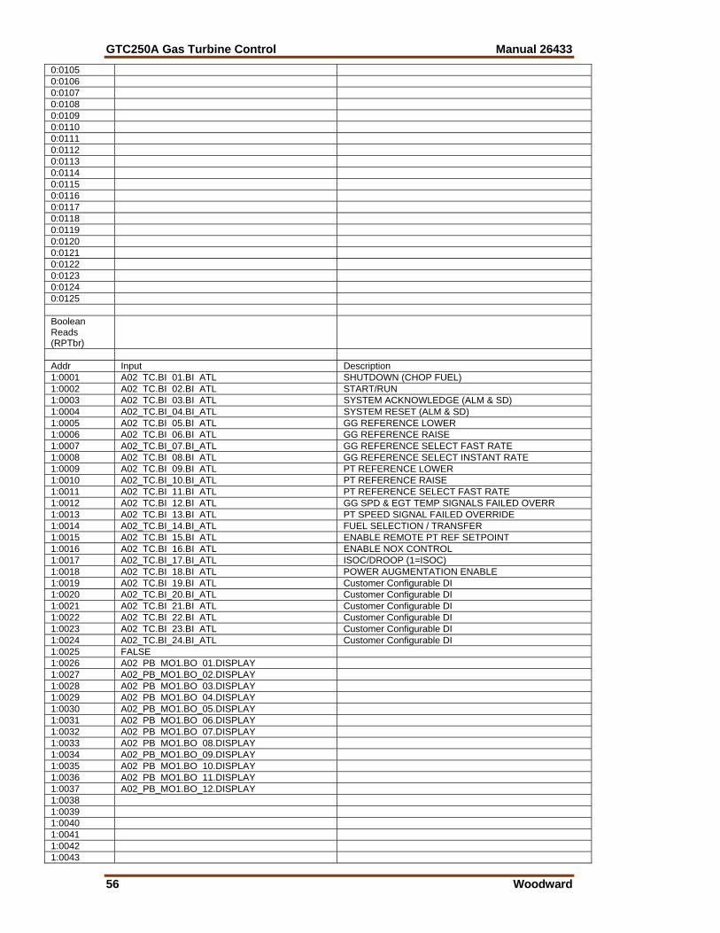
GTC250A Gas Turbine Control Manual 26433
56 Woodward
0:0105 0:0106 0:0107 0:0108 0:0109 0:0110 0:0111 0:0112 0:0113 0:0114 0:0115 0:0116 0:0117 0:0118 0:0119 0:0120 0:0121 0:0122 0:0123 0:0124 0:0125 Boolean Reads (RPTbr)
Addr Input Description 1:0001 A02 TC.BI 01.BI ATL SHUTDOWN (CHOP FUEL) 1:0002 A02 TC.BI 02.BI ATL START/RUN 1:0003 A02 TC.BI 03.BI ATL SYSTEM ACKNOWLEDGE (ALM & SD) 1:0004 A02_TC.BI_04.BI_ATL SYSTEM RESET (ALM & SD) 1:0005 A02 TC.BI 05.BI ATL GG REFERENCE LOWER 1:0006 A02 TC.BI 06.BI ATL GG REFERENCE RAISE 1:0007 A02_TC.BI_07.BI_ATL GG REFERENCE SELECT FAST RATE 1:0008 A02 TC.BI 08.BI ATL GG REFERENCE SELECT INSTANT RATE 1:0009 A02 TC.BI 09.BI ATL PT REFERENCE LOWER 1:0010 A02_TC.BI_10.BI_ATL PT REFERENCE RAISE 1:0011 A02 TC.BI 11.BI ATL PT REFERENCE SELECT FAST RATE 1:0012 A02 TC.BI 12.BI ATL GG SPD & EGT TEMP SIGNALS FAILED OVERR 1:0013 A02 TC.BI 13.BI ATL PT SPEED SIGNAL FAILED OVERRIDE 1:0014 A02_TC.BI_14.BI_ATL FUEL SELECTION / TRANSFER 1:0015 A02 TC.BI 15.BI ATL ENABLE REMOTE PT REF SETPOINT 1:0016 A02 TC.BI 16.BI ATL ENABLE NOX CONTROL 1:0017 A02_TC.BI_17.BI_ATL ISOC/DROOP (1=ISOC) 1:0018 A02 TC.BI 18.BI ATL POWER AUGMENTATION ENABLE 1:0019 A02 TC.BI 19.BI ATL Customer Configurable DI 1:0020 A02_TC.BI_20.BI_ATL Customer Configurable DI 1:0021 A02 TC.BI 21.BI ATL Customer Configurable DI 1:0022 A02 TC.BI 22.BI ATL Customer Configurable DI 1:0023 A02 TC.BI 23.BI ATL Customer Configurable DI 1:0024 A02_TC.BI_24.BI_ATL Customer Configurable DI 1:0025 FALSE 1:0026 A02 PB MO1.BO 01.DISPLAY 1:0027 A02_PB_MO1.BO_02.DISPLAY 1:0028 A02 PB MO1.BO 03.DISPLAY 1:0029 A02 PB MO1.BO 04.DISPLAY 1:0030 A02_PB_MO1.BO_05.DISPLAY 1:0031 A02 PB MO1.BO 06.DISPLAY 1:0032 A02 PB MO1.BO 07.DISPLAY 1:0033 A02 PB MO1.BO 08.DISPLAY 1:0034 A02_PB_MO1.BO_09.DISPLAY 1:0035 A02 PB MO1.BO 10.DISPLAY 1:0036 A02 PB MO1.BO 11.DISPLAY 1:0037 A02_PB_MO1.BO_12.DISPLAY 1:0038 1:0039 1:0040 1:0041 1:0042 1:0043
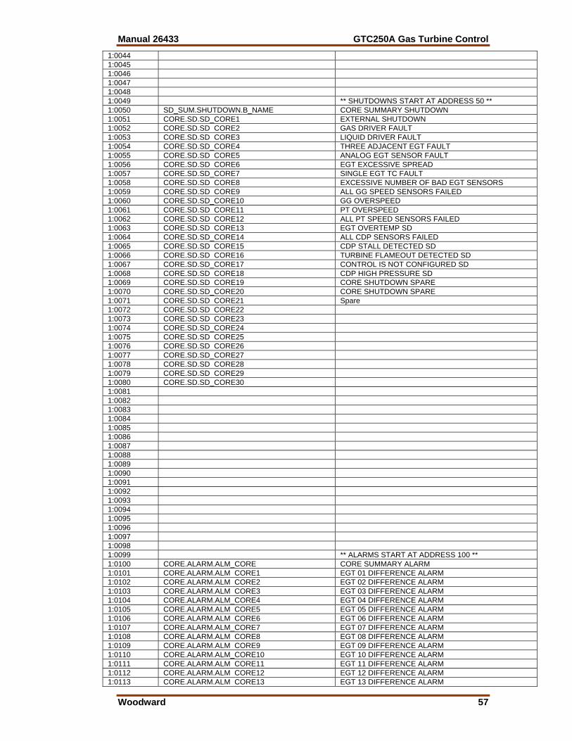
Manual 26433 GTC250A Gas Turbine Control
Woodward 57
1:0044 1:0045 1:0046 1:0047 1:0048 1:0049 ** SHUTDOWNS START AT ADDRESS 50 ** 1:0050 SD_SUM.SHUTDOWN.B_NAME CORE SUMMARY SHUTDOWN 1:0051 CORE.SD.SD_CORE1 EXTERNAL SHUTDOWN 1:0052 CORE.SD.SD CORE2 GAS DRIVER FAULT 1:0053 CORE.SD.SD CORE3 LIQUID DRIVER FAULT 1:0054 CORE.SD.SD_CORE4 THREE ADJACENT EGT FAULT 1:0055 CORE.SD.SD CORE5 ANALOG EGT SENSOR FAULT 1:0056 CORE.SD.SD CORE6 EGT EXCESSIVE SPREAD 1:0057 CORE.SD.SD_CORE7 SINGLE EGT TC FAULT 1:0058 CORE.SD.SD CORE8 EXCESSIVE NUMBER OF BAD EGT SENSORS 1:0059 CORE.SD.SD CORE9 ALL GG SPEED SENSORS FAILED 1:0060 CORE.SD.SD_CORE10 GG OVERSPEED 1:0061 CORE.SD.SD CORE11 PT OVERSPEED 1:0062 CORE.SD.SD CORE12 ALL PT SPEED SENSORS FAILED 1:0063 CORE.SD.SD CORE13 EGT OVERTEMP SD 1:0064 CORE.SD.SD_CORE14 ALL CDP SENSORS FAILED 1:0065 CORE.SD.SD CORE15 CDP STALL DETECTED SD 1:0066 CORE.SD.SD CORE16 TURBINE FLAMEOUT DETECTED SD 1:0067 CORE.SD.SD_CORE17 CONTROL IS NOT CONFIGURED SD 1:0068 CORE.SD.SD CORE18 CDP HIGH PRESSURE SD 1:0069 CORE.SD.SD CORE19 CORE SHUTDOWN SPARE 1:0070 CORE.SD.SD_CORE20 CORE SHUTDOWN SPARE 1:0071 CORE.SD.SD CORE21 Spare 1:0072 CORE.SD.SD CORE22 1:0073 CORE.SD.SD CORE23 1:0074 CORE.SD.SD_CORE24 1:0075 CORE.SD.SD CORE25 1:0076 CORE.SD.SD CORE26 1:0077 CORE.SD.SD_CORE27 1:0078 CORE.SD.SD CORE28 1:0079 CORE.SD.SD CORE29 1:0080 CORE.SD.SD_CORE30 1:0081 1:0082 1:0083 1:0084 1:0085 1:0086 1:0087 1:0088 1:0089 1:0090 1:0091 1:0092 1:0093 1:0094 1:0095 1:0096 1:0097 1:0098 1:0099 ** ALARMS START AT ADDRESS 100 ** 1:0100 CORE.ALARM.ALM_CORE CORE SUMMARY ALARM 1:0101 CORE.ALARM.ALM CORE1 EGT 01 DIFFERENCE ALARM 1:0102 CORE.ALARM.ALM CORE2 EGT 02 DIFFERENCE ALARM 1:0103 CORE.ALARM.ALM CORE3 EGT 03 DIFFERENCE ALARM 1:0104 CORE.ALARM.ALM_CORE4 EGT 04 DIFFERENCE ALARM 1:0105 CORE.ALARM.ALM CORE5 EGT 05 DIFFERENCE ALARM 1:0106 CORE.ALARM.ALM CORE6 EGT 06 DIFFERENCE ALARM 1:0107 CORE.ALARM.ALM_CORE7 EGT 07 DIFFERENCE ALARM 1:0108 CORE.ALARM.ALM CORE8 EGT 08 DIFFERENCE ALARM 1:0109 CORE.ALARM.ALM CORE9 EGT 09 DIFFERENCE ALARM 1:0110 CORE.ALARM.ALM_CORE10 EGT 10 DIFFERENCE ALARM 1:0111 CORE.ALARM.ALM CORE11 EGT 11 DIFFERENCE ALARM 1:0112 CORE.ALARM.ALM CORE12 EGT 12 DIFFERENCE ALARM 1:0113 CORE.ALARM.ALM CORE13 EGT 13 DIFFERENCE ALARM
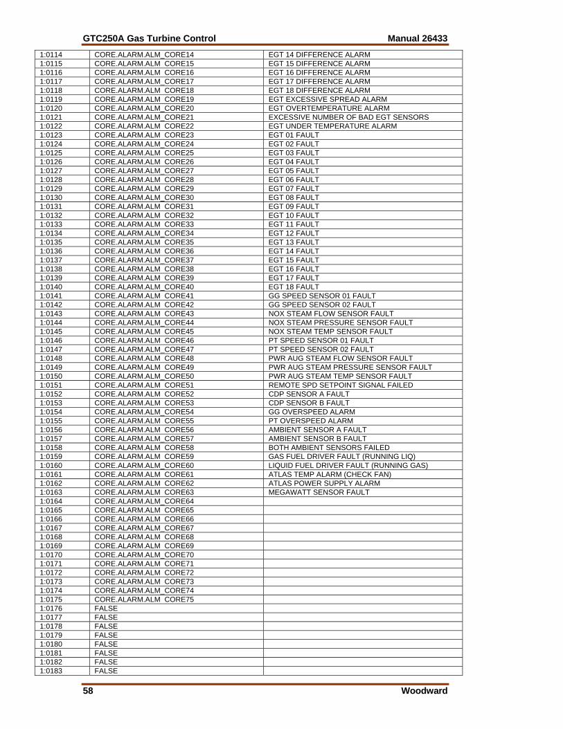
GTC250A Gas Turbine Control Manual 26433
58 Woodward
1:0114 CORE.ALARM.ALM_CORE14 EGT 14 DIFFERENCE ALARM 1:0115 CORE.ALARM.ALM CORE15 EGT 15 DIFFERENCE ALARM 1:0116 CORE.ALARM.ALM CORE16 EGT 16 DIFFERENCE ALARM 1:0117 CORE.ALARM.ALM_CORE17 EGT 17 DIFFERENCE ALARM 1:0118 CORE.ALARM.ALM CORE18 EGT 18 DIFFERENCE ALARM 1:0119 CORE.ALARM.ALM CORE19 EGT EXCESSIVE SPREAD ALARM 1:0120 CORE.ALARM.ALM_CORE20 EGT OVERTEMPERATURE ALARM 1:0121 CORE.ALARM.ALM_CORE21 EXCESSIVE NUMBER OF BAD EGT SENSORS 1:0122 CORE.ALARM.ALM CORE22 EGT UNDER TEMPERATURE ALARM 1:0123 CORE.ALARM.ALM CORE23 EGT 01 FAULT 1:0124 CORE.ALARM.ALM_CORE24 EGT 02 FAULT 1:0125 CORE.ALARM.ALM CORE25 EGT 03 FAULT 1:0126 CORE.ALARM.ALM CORE26 EGT 04 FAULT 1:0127 CORE.ALARM.ALM_CORE27 EGT 05 FAULT 1:0128 CORE.ALARM.ALM CORE28 EGT 06 FAULT 1:0129 CORE.ALARM.ALM CORE29 EGT 07 FAULT 1:0130 CORE.ALARM.ALM_CORE30 EGT 08 FAULT 1:0131 CORE.ALARM.ALM CORE31 EGT 09 FAULT 1:0132 CORE.ALARM.ALM CORE32 EGT 10 FAULT 1:0133 CORE.ALARM.ALM CORE33 EGT 11 FAULT 1:0134 CORE.ALARM.ALM_CORE34 EGT 12 FAULT 1:0135 CORE.ALARM.ALM CORE35 EGT 13 FAULT 1:0136 CORE.ALARM.ALM CORE36 EGT 14 FAULT 1:0137 CORE.ALARM.ALM_CORE37 EGT 15 FAULT 1:0138 CORE.ALARM.ALM CORE38 EGT 16 FAULT 1:0139 CORE.ALARM.ALM CORE39 EGT 17 FAULT 1:0140 CORE.ALARM.ALM_CORE40 EGT 18 FAULT 1:0141 CORE.ALARM.ALM CORE41 GG SPEED SENSOR 01 FAULT 1:0142 CORE.ALARM.ALM CORE42 GG SPEED SENSOR 02 FAULT 1:0143 CORE.ALARM.ALM CORE43 NOX STEAM FLOW SENSOR FAULT 1:0144 CORE.ALARM.ALM_CORE44 NOX STEAM PRESSURE SENSOR FAULT 1:0145 CORE.ALARM.ALM CORE45 NOX STEAM TEMP SENSOR FAULT 1:0146 CORE.ALARM.ALM CORE46 PT SPEED SENSOR 01 FAULT 1:0147 CORE.ALARM.ALM_CORE47 PT SPEED SENSOR 02 FAULT 1:0148 CORE.ALARM.ALM CORE48 PWR AUG STEAM FLOW SENSOR FAULT 1:0149 CORE.ALARM.ALM CORE49 PWR AUG STEAM PRESSURE SENSOR FAULT 1:0150 CORE.ALARM.ALM_CORE50 PWR AUG STEAM TEMP SENSOR FAULT 1:0151 CORE.ALARM.ALM CORE51 REMOTE SPD SETPOINT SIGNAL FAILED 1:0152 CORE.ALARM.ALM CORE52 CDP SENSOR A FAULT 1:0153 CORE.ALARM.ALM CORE53 CDP SENSOR B FAULT 1:0154 CORE.ALARM.ALM_CORE54 GG OVERSPEED ALARM 1:0155 CORE.ALARM.ALM CORE55 PT OVERSPEED ALARM 1:0156 CORE.ALARM.ALM CORE56 AMBIENT SENSOR A FAULT 1:0157 CORE.ALARM.ALM_CORE57 AMBIENT SENSOR B FAULT 1:0158 CORE.ALARM.ALM CORE58 BOTH AMBIENT SENSORS FAILED 1:0159 CORE.ALARM.ALM CORE59 GAS FUEL DRIVER FAULT (RUNNING LIQ) 1:0160 CORE.ALARM.ALM_CORE60 LIQUID FUEL DRIVER FAULT (RUNNING GAS) 1:0161 CORE.ALARM.ALM CORE61 ATLAS TEMP ALARM (CHECK FAN) 1:0162 CORE.ALARM.ALM CORE62 ATLAS POWER SUPPLY ALARM 1:0163 CORE.ALARM.ALM CORE63 MEGAWATT SENSOR FAULT 1:0164 CORE.ALARM.ALM_CORE64 1:0165 CORE.ALARM.ALM CORE65 1:0166 CORE.ALARM.ALM CORE66 1:0167 CORE.ALARM.ALM_CORE67 1:0168 CORE.ALARM.ALM CORE68 1:0169 CORE.ALARM.ALM CORE69 1:0170 CORE.ALARM.ALM_CORE70 1:0171 CORE.ALARM.ALM CORE71 1:0172 CORE.ALARM.ALM CORE72 1:0173 CORE.ALARM.ALM CORE73 1:0174 CORE.ALARM.ALM_CORE74 1:0175 CORE.ALARM.ALM CORE75 1:0176 FALSE 1:0177 FALSE 1:0178 FALSE 1:0179 FALSE 1:0180 FALSE 1:0181 FALSE 1:0182 FALSE 1:0183 FALSE
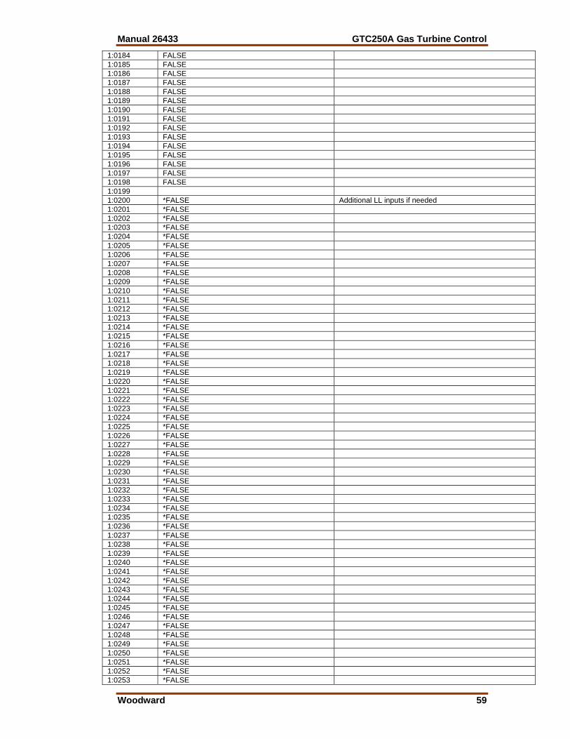
Manual 26433 GTC250A Gas Turbine Control
Woodward 59
1:0184 FALSE 1:0185 FALSE 1:0186 FALSE 1:0187 FALSE 1:0188 FALSE 1:0189 FALSE 1:0190 FALSE 1:0191 FALSE 1:0192 FALSE 1:0193 FALSE 1:0194 FALSE 1:0195 FALSE 1:0196 FALSE 1:0197 FALSE 1:0198 FALSE 1:0199 1:0200 *FALSE Additional LL inputs if needed 1:0201 *FALSE 1:0202 *FALSE 1:0203 *FALSE 1:0204 *FALSE 1:0205 *FALSE 1:0206 *FALSE 1:0207 *FALSE 1:0208 *FALSE 1:0209 *FALSE 1:0210 *FALSE 1:0211 *FALSE 1:0212 *FALSE 1:0213 *FALSE 1:0214 *FALSE 1:0215 *FALSE 1:0216 *FALSE 1:0217 *FALSE 1:0218 *FALSE 1:0219 *FALSE 1:0220 *FALSE 1:0221 *FALSE 1:0222 *FALSE 1:0223 *FALSE 1:0224 *FALSE 1:0225 *FALSE 1:0226 *FALSE 1:0227 *FALSE 1:0228 *FALSE 1:0229 *FALSE 1:0230 *FALSE 1:0231 *FALSE 1:0232 *FALSE 1:0233 *FALSE 1:0234 *FALSE 1:0235 *FALSE 1:0236 *FALSE 1:0237 *FALSE 1:0238 *FALSE 1:0239 *FALSE 1:0240 *FALSE 1:0241 *FALSE 1:0242 *FALSE 1:0243 *FALSE 1:0244 *FALSE 1:0245 *FALSE 1:0246 *FALSE 1:0247 *FALSE 1:0248 *FALSE 1:0249 *FALSE 1:0250 *FALSE 1:0251 *FALSE 1:0252 *FALSE 1:0253 *FALSE
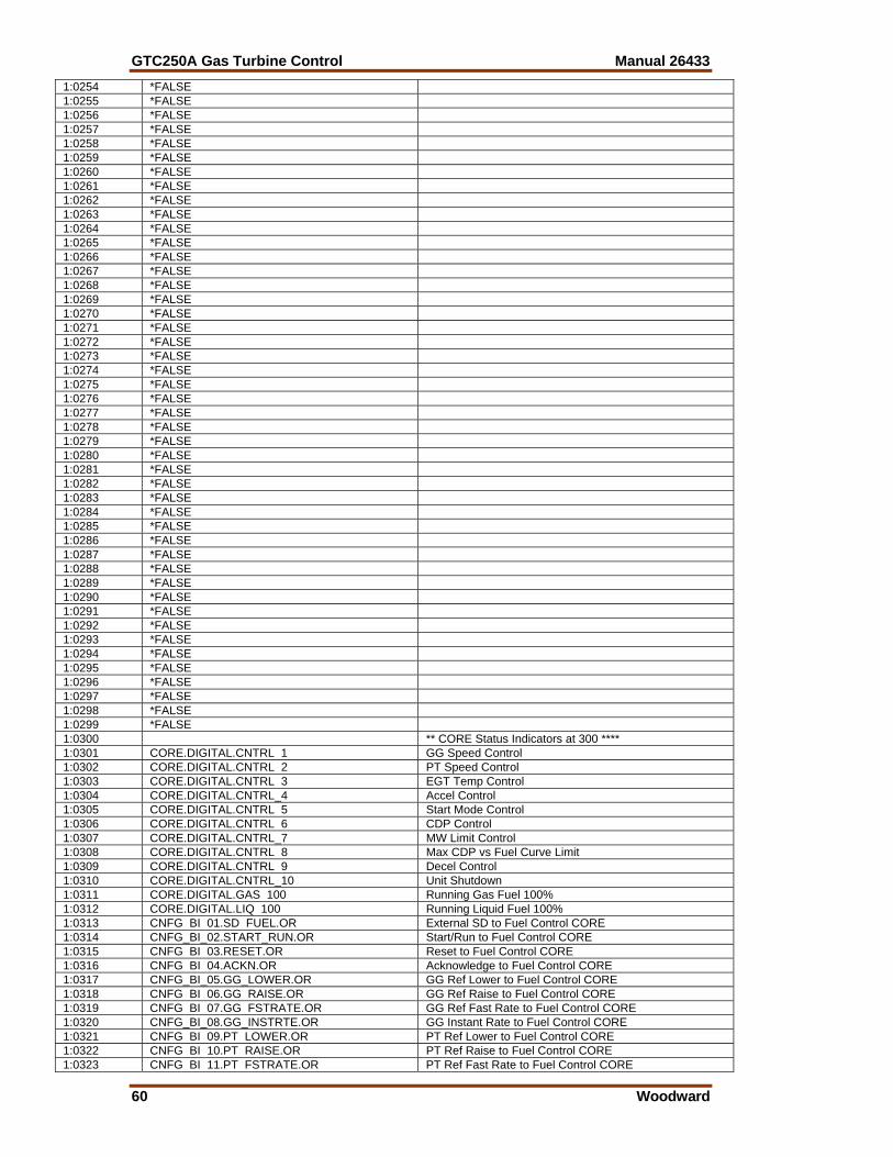
GTC250A Gas Turbine Control Manual 26433
60 Woodward
1:0254 *FALSE 1:0255 *FALSE 1:0256 *FALSE 1:0257 *FALSE 1:0258 *FALSE 1:0259 *FALSE 1:0260 *FALSE 1:0261 *FALSE 1:0262 *FALSE 1:0263 *FALSE 1:0264 *FALSE 1:0265 *FALSE 1:0266 *FALSE 1:0267 *FALSE 1:0268 *FALSE 1:0269 *FALSE 1:0270 *FALSE 1:0271 *FALSE 1:0272 *FALSE 1:0273 *FALSE 1:0274 *FALSE 1:0275 *FALSE 1:0276 *FALSE 1:0277 *FALSE 1:0278 *FALSE 1:0279 *FALSE 1:0280 *FALSE 1:0281 *FALSE 1:0282 *FALSE 1:0283 *FALSE 1:0284 *FALSE 1:0285 *FALSE 1:0286 *FALSE 1:0287 *FALSE 1:0288 *FALSE 1:0289 *FALSE 1:0290 *FALSE 1:0291 *FALSE 1:0292 *FALSE 1:0293 *FALSE 1:0294 *FALSE 1:0295 *FALSE 1:0296 *FALSE 1:0297 *FALSE 1:0298 *FALSE 1:0299 *FALSE 1:0300 ** CORE Status Indicators at 300 **** 1:0301 CORE.DIGITAL.CNTRL 1 GG Speed Control 1:0302 CORE.DIGITAL.CNTRL 2 PT Speed Control 1:0303 CORE.DIGITAL.CNTRL 3 EGT Temp Control 1:0304 CORE.DIGITAL.CNTRL_4 Accel Control 1:0305 CORE.DIGITAL.CNTRL 5 Start Mode Control 1:0306 CORE.DIGITAL.CNTRL 6 CDP Control 1:0307 CORE.DIGITAL.CNTRL_7 MW Limit Control 1:0308 CORE.DIGITAL.CNTRL 8 Max CDP vs Fuel Curve Limit 1:0309 CORE.DIGITAL.CNTRL 9 Decel Control 1:0310 CORE.DIGITAL.CNTRL_10 Unit Shutdown 1:0311 CORE.DIGITAL.GAS 100 Running Gas Fuel 100% 1:0312 CORE.DIGITAL.LIQ 100 Running Liquid Fuel 100% 1:0313 CNFG BI 01.SD FUEL.OR External SD to Fuel Control CORE 1:0314 CNFG_BI_02.START_RUN.OR Start/Run to Fuel Control CORE 1:0315 CNFG BI 03.RESET.OR Reset to Fuel Control CORE 1:0316 CNFG BI 04.ACKN.OR Acknowledge to Fuel Control CORE 1:0317 CNFG_BI_05.GG_LOWER.OR GG Ref Lower to Fuel Control CORE 1:0318 CNFG BI 06.GG RAISE.OR GG Ref Raise to Fuel Control CORE 1:0319 CNFG BI 07.GG FSTRATE.OR GG Ref Fast Rate to Fuel Control CORE 1:0320 CNFG_BI_08.GG_INSTRTE.OR GG Instant Rate to Fuel Control CORE 1:0321 CNFG BI 09.PT LOWER.OR PT Ref Lower to Fuel Control CORE 1:0322 CNFG BI 10.PT RAISE.OR PT Ref Raise to Fuel Control CORE 1:0323 CNFG BI 11.PT FSTRATE.OR PT Ref Fast Rate to Fuel Control CORE
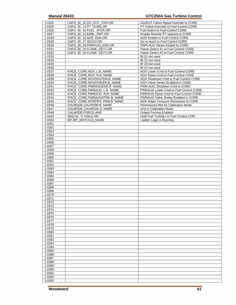
Manual 26433 GTC250A Gas Turbine Control
Woodward 61
1:0324 CNFG_BI_12.GG_EGT_OVR.OR GG/EGT Failed Signal Override to CORE 1:0325 CNFG BI 13.PT OVRD.OR PT Failed Override to Fuel Control CORE 1:0326 CNFG BI 14.FUEL XFER.OR Fuel Select to Fuel Control CORE 1:0327 CNFG_BI_15.ENBL_RMT.OR Enable Remote PT setpoint to CORE 1:0328 CNFG BI 16.NOX ENA.OR NOX Enable to Fuel Control CORE 1:0329 CNFG BI 17.ISOCH.OR Go to Isoch to Fuel Control CORE 1:0330 CNFG_BI_18.PWRAUG_ENA.OR PWR AUG Steam Enable to CORE 1:0331 CNFG_BI_19.FLAME_DET1.OR Flame Detect #1 to Fuel Control CORE 1:0332 CNFG BI 20.FLAME DET2.OR Flame Detect #2 to Fuel Control CORE 1:0333 BI 21 not used 1:0334 BI 22 not used 1:0335 BI 23 not used 1:0336 BI 24 not used 1:0337 IFACE_CORE.NOX_L.B_NAME NOX Lower Cmd to Fuel Control CORE 1:0338 IFACE CORE.NOX R.B NAME NOX Raise Cmd to Fuel Control CORE 1:0339 IFACE CORE.NOXSHUTDN.B NAME NOX Shutdown Cmd to Fuel Control CORE 1:0340 IFACE_CORE.NOXSTRKEN.B_NAME NOX Valve Stroke Enabled to CORE 1:0341 IFACE CORE.PWRAUGESD.B NAME PWR AUG Shutdown Cmd to CORE 1:0342 IFACE CORE.PWRAUG L.B NAME PWRAUG Lower Cmd to Fuel Control CORE 1:0343 IFACE CORE.PWRAUG R.B NAME PWRAUG Raise Cmd to Fuel Control CORE 1:0344 IFACE_CORE.PWRAUGSTRK.B_NAME PWRAUG Valve Stroke Enabled to CORE 1:0345 IFACE CORE.WTRPRS PRM.B NAME NOX Water Pressure Permissive to CORE 1:0346 CALMODE.CALPERM.B NAME Permissives Met for Calibration Mode 1:0347 CALMODE.CALMODE.B_NAME Unit in Calibration Mode 1:0348 CALMODE.FORCE.AND Output Forcing Enabled 1:0349 SEQ.GL X HOLD.OR Hold Fuel Transfer to Fuel Control COR 1:0350 MP.MP_WATCH.B_NAME Ladder Logic is Running 1:0351 1:0352 1:0353 1:0354 1:0355 1:0356 1:0357 1:0358 1:0359 1:0360 1:0361 1:0362 1:0363 1:0364 1:0365 1:0366 1:0367 1:0368 1:0369 1:0370 1:0371 1:0372 1:0373 1:0374 1:0375 1:0376 1:0377 1:0378 1:0379 1:0380 1:0381 1:0382 1:0383 1:0384 1:0385 1:0386 1:0387 1:0388 1:0389 1:0390 1:0391 1:0392 1:0393
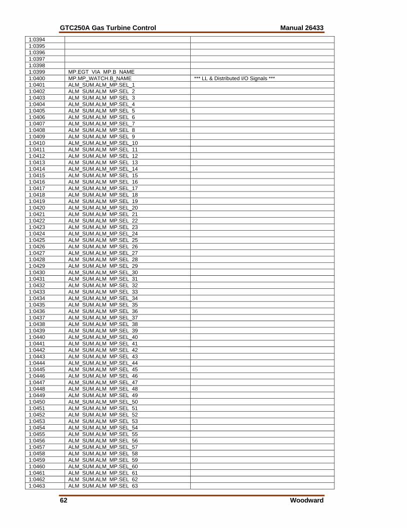
GTC250A Gas Turbine Control Manual 26433
62 Woodward
1:0394 1:0395 1:0396 1:0397 1:0398 1:0399 MP.EGT VIA MP.B NAME 1:0400 MP.MP_WATCH.B_NAME *** LL & Distributed I/O Signals *** 1:0401 ALM_SUM.ALM_MP.SEL_1 1:0402 ALM SUM.ALM MP.SEL 2 1:0403 ALM SUM.ALM MP.SEL 3 1:0404 ALM_SUM.ALM_MP.SEL_4 1:0405 ALM SUM.ALM MP.SEL 5 1:0406 ALM SUM.ALM MP.SEL 6 1:0407 ALM_SUM.ALM_MP.SEL_7 1:0408 ALM SUM.ALM MP.SEL 8 1:0409 ALM SUM.ALM MP.SEL 9 1:0410 ALM_SUM.ALM_MP.SEL_10 1:0411 ALM SUM.ALM MP.SEL 11 1:0412 ALM SUM.ALM MP.SEL 12 1:0413 ALM SUM.ALM MP.SEL 13 1:0414 ALM_SUM.ALM_MP.SEL_14 1:0415 ALM SUM.ALM MP.SEL 15 1:0416 ALM SUM.ALM MP.SEL 16 1:0417 ALM_SUM.ALM_MP.SEL_17 1:0418 ALM SUM.ALM MP.SEL 18 1:0419 ALM SUM.ALM MP.SEL 19 1:0420 ALM_SUM.ALM_MP.SEL_20 1:0421 ALM SUM.ALM MP.SEL 21 1:0422 ALM SUM.ALM MP.SEL 22 1:0423 ALM SUM.ALM MP.SEL 23 1:0424 ALM_SUM.ALM_MP.SEL_24 1:0425 ALM SUM.ALM MP.SEL 25 1:0426 ALM SUM.ALM MP.SEL 26 1:0427 ALM_SUM.ALM_MP.SEL_27 1:0428 ALM SUM.ALM MP.SEL 28 1:0429 ALM SUM.ALM MP.SEL 29 1:0430 ALM_SUM.ALM_MP.SEL_30 1:0431 ALM SUM.ALM MP.SEL 31 1:0432 ALM SUM.ALM MP.SEL 32 1:0433 ALM SUM.ALM MP.SEL 33 1:0434 ALM_SUM.ALM_MP.SEL_34 1:0435 ALM SUM.ALM MP.SEL 35 1:0436 ALM SUM.ALM MP.SEL 36 1:0437 ALM_SUM.ALM_MP.SEL_37 1:0438 ALM SUM.ALM MP.SEL 38 1:0439 ALM SUM.ALM MP.SEL 39 1:0440 ALM_SUM.ALM_MP.SEL_40 1:0441 ALM SUM.ALM MP.SEL 41 1:0442 ALM SUM.ALM MP.SEL 42 1:0443 ALM SUM.ALM MP.SEL 43 1:0444 ALM_SUM.ALM_MP.SEL_44 1:0445 ALM SUM.ALM MP.SEL 45 1:0446 ALM SUM.ALM MP.SEL 46 1:0447 ALM_SUM.ALM_MP.SEL_47 1:0448 ALM SUM.ALM MP.SEL 48 1:0449 ALM SUM.ALM MP.SEL 49 1:0450 ALM_SUM.ALM_MP.SEL_50 1:0451 ALM SUM.ALM MP.SEL 51 1:0452 ALM SUM.ALM MP.SEL 52 1:0453 ALM SUM.ALM MP.SEL 53 1:0454 ALM_SUM.ALM_MP.SEL_54 1:0455 ALM SUM.ALM MP.SEL 55 1:0456 ALM SUM.ALM MP.SEL 56 1:0457 ALM_SUM.ALM_MP.SEL_57 1:0458 ALM SUM.ALM MP.SEL 58 1:0459 ALM SUM.ALM MP.SEL 59 1:0460 ALM_SUM.ALM_MP.SEL_60 1:0461 ALM SUM.ALM MP.SEL 61 1:0462 ALM SUM.ALM MP.SEL 62 1:0463 ALM SUM.ALM MP.SEL 63
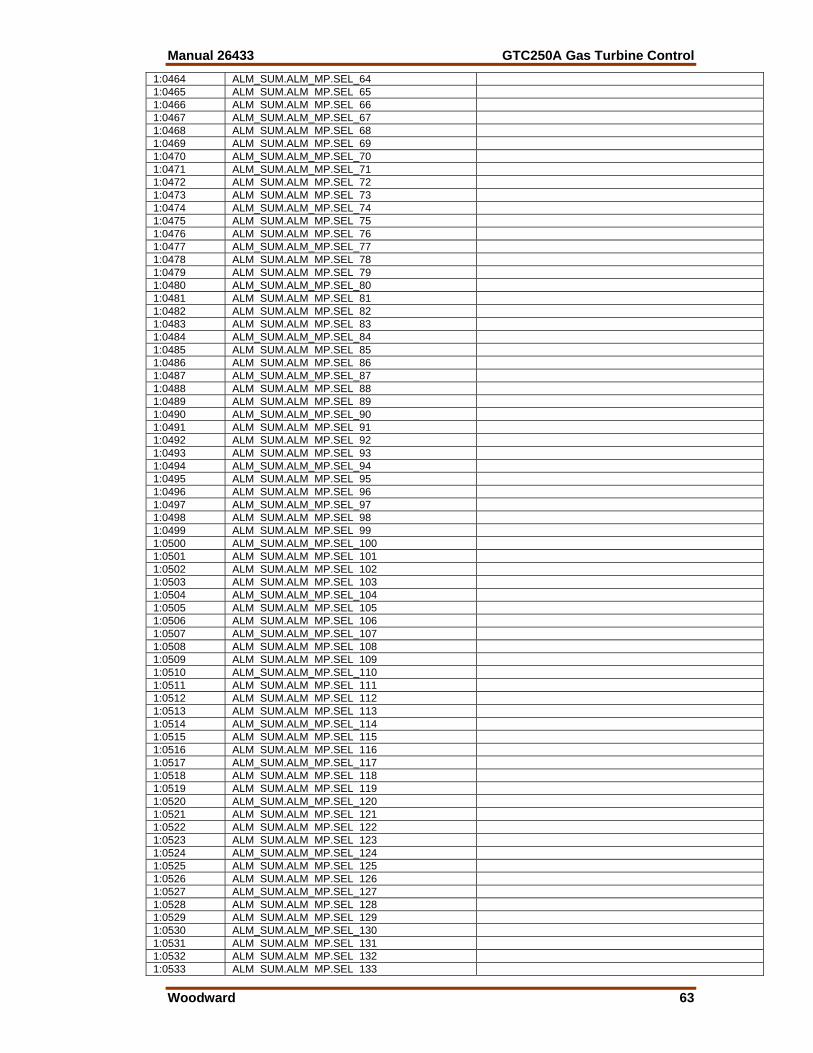
Manual 26433 GTC250A Gas Turbine Control
Woodward 63
1:0464 ALM_SUM.ALM_MP.SEL_64 1:0465 ALM SUM.ALM MP.SEL 65 1:0466 ALM SUM.ALM MP.SEL 66 1:0467 ALM_SUM.ALM_MP.SEL_67 1:0468 ALM SUM.ALM MP.SEL 68 1:0469 ALM SUM.ALM MP.SEL 69 1:0470 ALM_SUM.ALM_MP.SEL_70 1:0471 ALM_SUM.ALM_MP.SEL_71 1:0472 ALM SUM.ALM MP.SEL 72 1:0473 ALM SUM.ALM MP.SEL 73 1:0474 ALM_SUM.ALM_MP.SEL_74 1:0475 ALM SUM.ALM MP.SEL 75 1:0476 ALM SUM.ALM MP.SEL 76 1:0477 ALM_SUM.ALM_MP.SEL_77 1:0478 ALM SUM.ALM MP.SEL 78 1:0479 ALM SUM.ALM MP.SEL 79 1:0480 ALM_SUM.ALM_MP.SEL_80 1:0481 ALM SUM.ALM MP.SEL 81 1:0482 ALM SUM.ALM MP.SEL 82 1:0483 ALM SUM.ALM MP.SEL 83 1:0484 ALM_SUM.ALM_MP.SEL_84 1:0485 ALM SUM.ALM MP.SEL 85 1:0486 ALM SUM.ALM MP.SEL 86 1:0487 ALM_SUM.ALM_MP.SEL_87 1:0488 ALM SUM.ALM MP.SEL 88 1:0489 ALM SUM.ALM MP.SEL 89 1:0490 ALM_SUM.ALM_MP.SEL_90 1:0491 ALM SUM.ALM MP.SEL 91 1:0492 ALM SUM.ALM MP.SEL 92 1:0493 ALM SUM.ALM MP.SEL 93 1:0494 ALM_SUM.ALM_MP.SEL_94 1:0495 ALM SUM.ALM MP.SEL 95 1:0496 ALM SUM.ALM MP.SEL 96 1:0497 ALM_SUM.ALM_MP.SEL_97 1:0498 ALM SUM.ALM MP.SEL 98 1:0499 ALM SUM.ALM MP.SEL 99 1:0500 ALM_SUM.ALM_MP.SEL_100 1:0501 ALM SUM.ALM MP.SEL 101 1:0502 ALM SUM.ALM MP.SEL 102 1:0503 ALM SUM.ALM MP.SEL 103 1:0504 ALM_SUM.ALM_MP.SEL_104 1:0505 ALM SUM.ALM MP.SEL 105 1:0506 ALM SUM.ALM MP.SEL 106 1:0507 ALM_SUM.ALM_MP.SEL_107 1:0508 ALM SUM.ALM MP.SEL 108 1:0509 ALM SUM.ALM MP.SEL 109 1:0510 ALM_SUM.ALM_MP.SEL_110 1:0511 ALM SUM.ALM MP.SEL 111 1:0512 ALM SUM.ALM MP.SEL 112 1:0513 ALM SUM.ALM MP.SEL 113 1:0514 ALM_SUM.ALM_MP.SEL_114 1:0515 ALM SUM.ALM MP.SEL 115 1:0516 ALM SUM.ALM MP.SEL 116 1:0517 ALM_SUM.ALM_MP.SEL_117 1:0518 ALM SUM.ALM MP.SEL 118 1:0519 ALM SUM.ALM MP.SEL 119 1:0520 ALM_SUM.ALM_MP.SEL_120 1:0521 ALM SUM.ALM MP.SEL 121 1:0522 ALM SUM.ALM MP.SEL 122 1:0523 ALM SUM.ALM MP.SEL 123 1:0524 ALM_SUM.ALM_MP.SEL_124 1:0525 ALM SUM.ALM MP.SEL 125 1:0526 ALM SUM.ALM MP.SEL 126 1:0527 ALM_SUM.ALM_MP.SEL_127 1:0528 ALM SUM.ALM MP.SEL 128 1:0529 ALM SUM.ALM MP.SEL 129 1:0530 ALM_SUM.ALM_MP.SEL_130 1:0531 ALM SUM.ALM MP.SEL 131 1:0532 ALM SUM.ALM MP.SEL 132 1:0533 ALM SUM.ALM MP.SEL 133
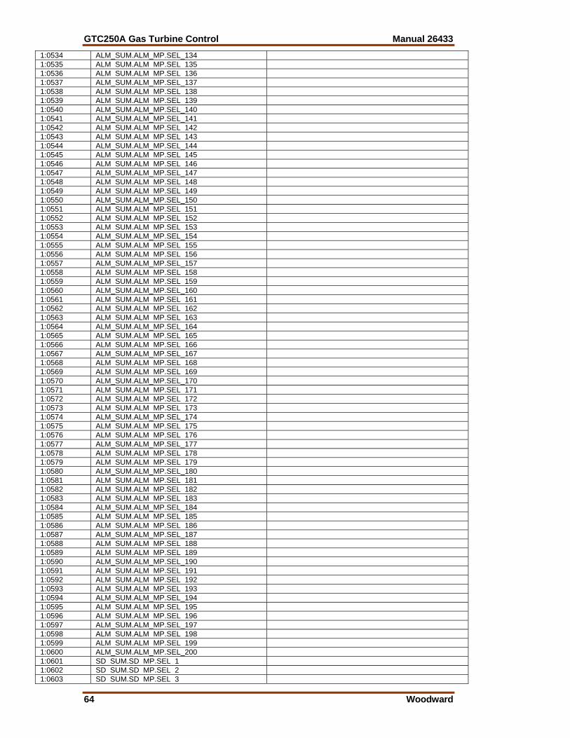
GTC250A Gas Turbine Control Manual 26433
64 Woodward
1:0534 ALM_SUM.ALM_MP.SEL_134 1:0535 ALM SUM.ALM MP.SEL 135 1:0536 ALM SUM.ALM MP.SEL 136 1:0537 ALM_SUM.ALM_MP.SEL_137 1:0538 ALM SUM.ALM MP.SEL 138 1:0539 ALM SUM.ALM MP.SEL 139 1:0540 ALM_SUM.ALM_MP.SEL_140 1:0541 ALM_SUM.ALM_MP.SEL_141 1:0542 ALM SUM.ALM MP.SEL 142 1:0543 ALM SUM.ALM MP.SEL 143 1:0544 ALM_SUM.ALM_MP.SEL_144 1:0545 ALM SUM.ALM MP.SEL 145 1:0546 ALM SUM.ALM MP.SEL 146 1:0547 ALM_SUM.ALM_MP.SEL_147 1:0548 ALM SUM.ALM MP.SEL 148 1:0549 ALM SUM.ALM MP.SEL 149 1:0550 ALM_SUM.ALM_MP.SEL_150 1:0551 ALM SUM.ALM MP.SEL 151 1:0552 ALM SUM.ALM MP.SEL 152 1:0553 ALM SUM.ALM MP.SEL 153 1:0554 ALM_SUM.ALM_MP.SEL_154 1:0555 ALM SUM.ALM MP.SEL 155 1:0556 ALM SUM.ALM MP.SEL 156 1:0557 ALM_SUM.ALM_MP.SEL_157 1:0558 ALM SUM.ALM MP.SEL 158 1:0559 ALM SUM.ALM MP.SEL 159 1:0560 ALM_SUM.ALM_MP.SEL_160 1:0561 ALM SUM.ALM MP.SEL 161 1:0562 ALM SUM.ALM MP.SEL 162 1:0563 ALM SUM.ALM MP.SEL 163 1:0564 ALM_SUM.ALM_MP.SEL_164 1:0565 ALM SUM.ALM MP.SEL 165 1:0566 ALM SUM.ALM MP.SEL 166 1:0567 ALM_SUM.ALM_MP.SEL_167 1:0568 ALM SUM.ALM MP.SEL 168 1:0569 ALM SUM.ALM MP.SEL 169 1:0570 ALM_SUM.ALM_MP.SEL_170 1:0571 ALM SUM.ALM MP.SEL 171 1:0572 ALM SUM.ALM MP.SEL 172 1:0573 ALM SUM.ALM MP.SEL 173 1:0574 ALM_SUM.ALM_MP.SEL_174 1:0575 ALM SUM.ALM MP.SEL 175 1:0576 ALM SUM.ALM MP.SEL 176 1:0577 ALM_SUM.ALM_MP.SEL_177 1:0578 ALM SUM.ALM MP.SEL 178 1:0579 ALM SUM.ALM MP.SEL 179 1:0580 ALM_SUM.ALM_MP.SEL_180 1:0581 ALM SUM.ALM MP.SEL 181 1:0582 ALM SUM.ALM MP.SEL 182 1:0583 ALM SUM.ALM MP.SEL 183 1:0584 ALM_SUM.ALM_MP.SEL_184 1:0585 ALM SUM.ALM MP.SEL 185 1:0586 ALM SUM.ALM MP.SEL 186 1:0587 ALM_SUM.ALM_MP.SEL_187 1:0588 ALM SUM.ALM MP.SEL 188 1:0589 ALM SUM.ALM MP.SEL 189 1:0590 ALM_SUM.ALM_MP.SEL_190 1:0591 ALM SUM.ALM MP.SEL 191 1:0592 ALM SUM.ALM MP.SEL 192 1:0593 ALM SUM.ALM MP.SEL 193 1:0594 ALM_SUM.ALM_MP.SEL_194 1:0595 ALM SUM.ALM MP.SEL 195 1:0596 ALM SUM.ALM MP.SEL 196 1:0597 ALM_SUM.ALM_MP.SEL_197 1:0598 ALM SUM.ALM MP.SEL 198 1:0599 ALM SUM.ALM MP.SEL 199 1:0600 ALM_SUM.ALM_MP.SEL_200 1:0601 SD SUM.SD MP.SEL 1 1:0602 SD SUM.SD MP.SEL 2 1:0603 SD SUM.SD MP.SEL 3
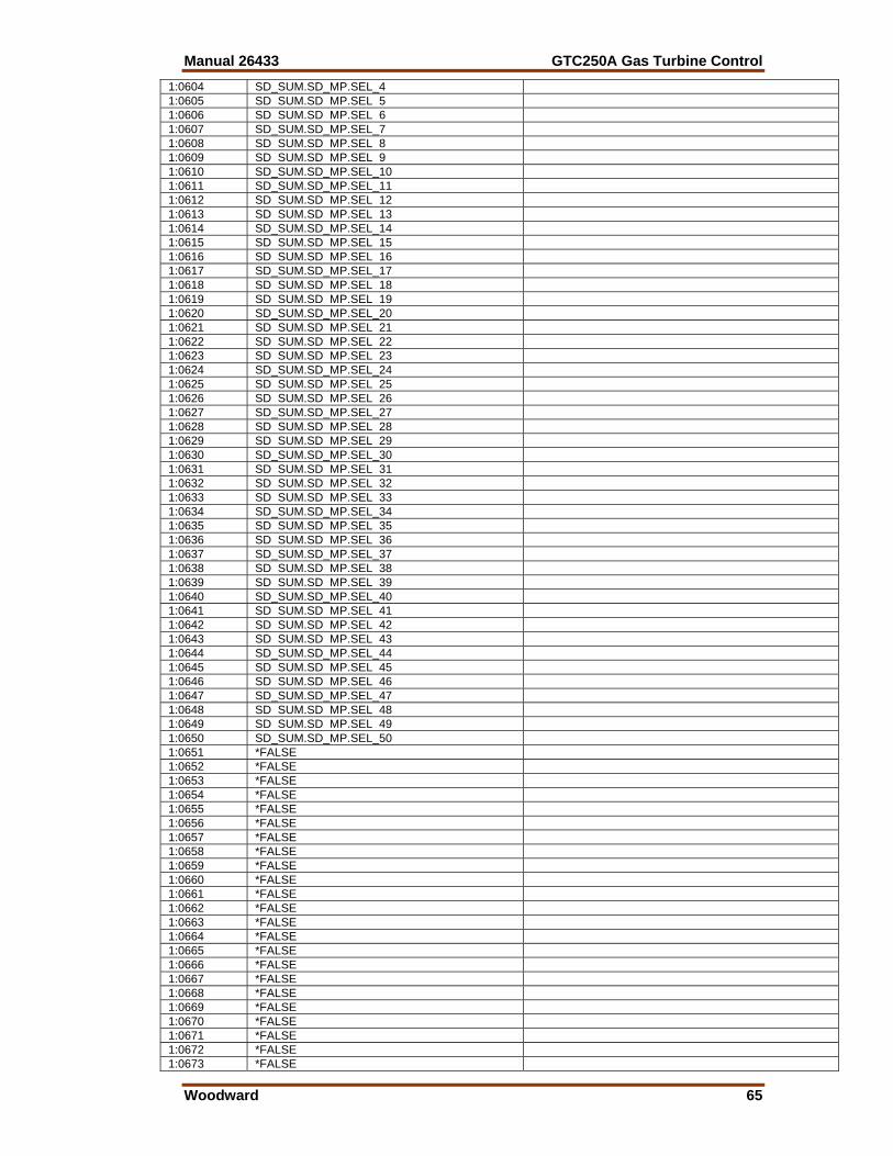
Manual 26433 GTC250A Gas Turbine Control
Woodward 65
1:0604 SD_SUM.SD_MP.SEL_4 1:0605 SD SUM.SD MP.SEL 5 1:0606 SD SUM.SD MP.SEL 6 1:0607 SD_SUM.SD_MP.SEL_7 1:0608 SD SUM.SD MP.SEL 8 1:0609 SD SUM.SD MP.SEL 9 1:0610 SD_SUM.SD_MP.SEL_10 1:0611 SD_SUM.SD_MP.SEL_11 1:0612 SD SUM.SD MP.SEL 12 1:0613 SD SUM.SD MP.SEL 13 1:0614 SD_SUM.SD_MP.SEL_14 1:0615 SD SUM.SD MP.SEL 15 1:0616 SD SUM.SD MP.SEL 16 1:0617 SD_SUM.SD_MP.SEL_17 1:0618 SD SUM.SD MP.SEL 18 1:0619 SD SUM.SD MP.SEL 19 1:0620 SD_SUM.SD_MP.SEL_20 1:0621 SD SUM.SD MP.SEL 21 1:0622 SD SUM.SD MP.SEL 22 1:0623 SD SUM.SD MP.SEL 23 1:0624 SD_SUM.SD_MP.SEL_24 1:0625 SD SUM.SD MP.SEL 25 1:0626 SD SUM.SD MP.SEL 26 1:0627 SD_SUM.SD_MP.SEL_27 1:0628 SD SUM.SD MP.SEL 28 1:0629 SD SUM.SD MP.SEL 29 1:0630 SD_SUM.SD_MP.SEL_30 1:0631 SD SUM.SD MP.SEL 31 1:0632 SD SUM.SD MP.SEL 32 1:0633 SD SUM.SD MP.SEL 33 1:0634 SD_SUM.SD_MP.SEL_34 1:0635 SD SUM.SD MP.SEL 35 1:0636 SD SUM.SD MP.SEL 36 1:0637 SD_SUM.SD_MP.SEL_37 1:0638 SD SUM.SD MP.SEL 38 1:0639 SD SUM.SD MP.SEL 39 1:0640 SD_SUM.SD_MP.SEL_40 1:0641 SD SUM.SD MP.SEL 41 1:0642 SD SUM.SD MP.SEL 42 1:0643 SD SUM.SD MP.SEL 43 1:0644 SD_SUM.SD_MP.SEL_44 1:0645 SD SUM.SD MP.SEL 45 1:0646 SD SUM.SD MP.SEL 46 1:0647 SD_SUM.SD_MP.SEL_47 1:0648 SD SUM.SD MP.SEL 48 1:0649 SD SUM.SD MP.SEL 49 1:0650 SD_SUM.SD_MP.SEL_50 1:0651 *FALSE 1:0652 *FALSE 1:0653 *FALSE 1:0654 *FALSE 1:0655 *FALSE 1:0656 *FALSE 1:0657 *FALSE 1:0658 *FALSE 1:0659 *FALSE 1:0660 *FALSE 1:0661 *FALSE 1:0662 *FALSE 1:0663 *FALSE 1:0664 *FALSE 1:0665 *FALSE 1:0666 *FALSE 1:0667 *FALSE 1:0668 *FALSE 1:0669 *FALSE 1:0670 *FALSE 1:0671 *FALSE 1:0672 *FALSE 1:0673 *FALSE
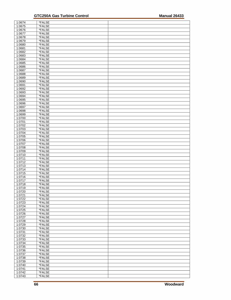
GTC250A Gas Turbine Control Manual 26433
66 Woodward
1:0674 *FALSE 1:0675 *FALSE 1:0676 *FALSE 1:0677 *FALSE 1:0678 *FALSE 1:0679 *FALSE 1:0680 *FALSE 1:0681 *FALSE 1:0682 *FALSE 1:0683 *FALSE 1:0684 *FALSE 1:0685 *FALSE 1:0686 *FALSE 1:0687 *FALSE 1:0688 *FALSE 1:0689 *FALSE 1:0690 *FALSE 1:0691 *FALSE 1:0692 *FALSE 1:0693 *FALSE 1:0694 *FALSE 1:0695 *FALSE 1:0696 *FALSE 1:0697 *FALSE 1:0698 *FALSE 1:0699 *FALSE 1:0700 *FALSE 1:0701 *FALSE 1:0702 *FALSE 1:0703 *FALSE 1:0704 *FALSE 1:0705 *FALSE 1:0706 *FALSE 1:0707 *FALSE 1:0708 *FALSE 1:0709 *FALSE 1:0710 *FALSE 1:0711 *FALSE 1:0712 *FALSE 1:0713 *FALSE 1:0714 *FALSE 1:0715 *FALSE 1:0716 *FALSE 1:0717 *FALSE 1:0718 *FALSE 1:0719 *FALSE 1:0720 *FALSE 1:0721 *FALSE 1:0722 *FALSE 1:0723 *FALSE 1:0724 *FALSE 1:0725 *FALSE 1:0726 *FALSE 1:0727 *FALSE 1:0728 *FALSE 1:0729 *FALSE 1:0730 *FALSE 1:0731 *FALSE 1:0732 *FALSE 1:0733 *FALSE 1:0734 *FALSE 1:0735 *FALSE 1:0736 *FALSE 1:0737 *FALSE 1:0738 *FALSE 1:0739 *FALSE 1:0740 *FALSE 1:0741 *FALSE 1:0742 *FALSE 1:0743 *FALSE
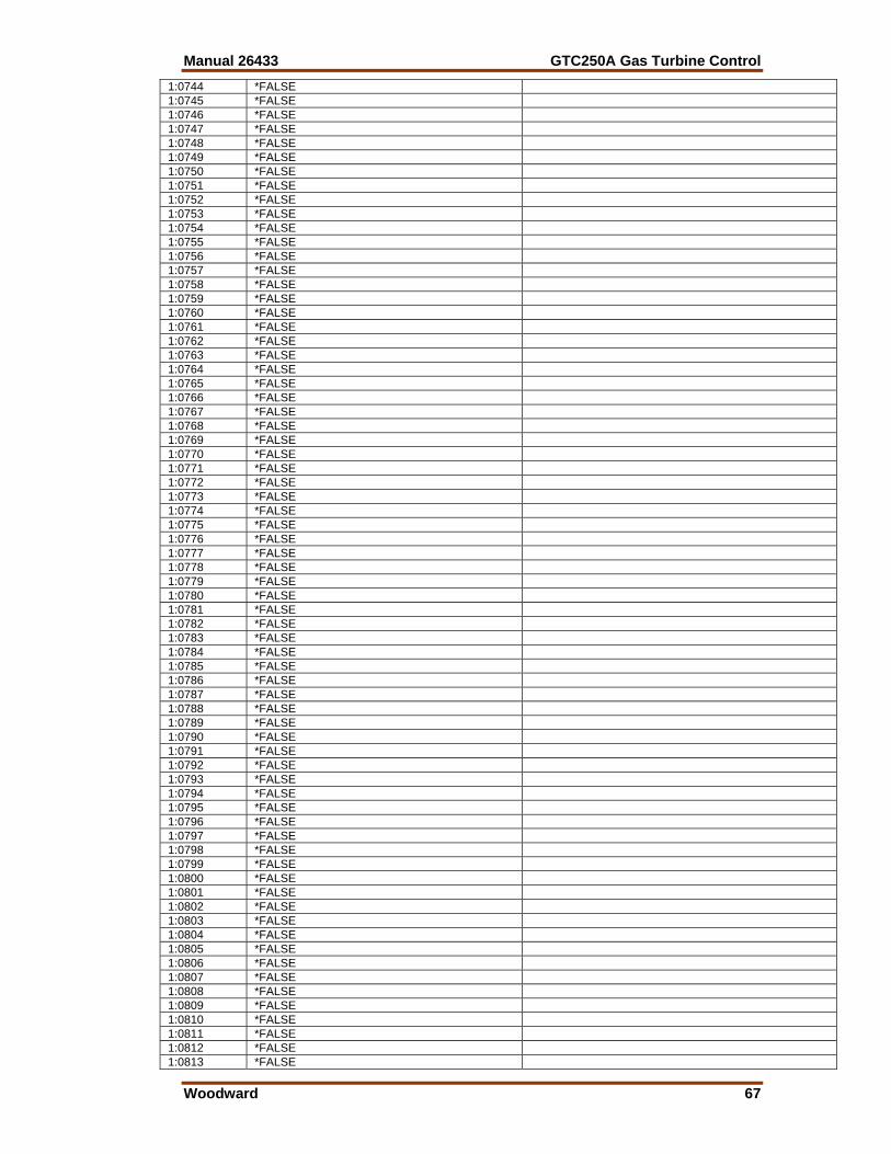
Manual 26433 GTC250A Gas Turbine Control
Woodward 67
1:0744 *FALSE 1:0745 *FALSE 1:0746 *FALSE 1:0747 *FALSE 1:0748 *FALSE 1:0749 *FALSE 1:0750 *FALSE 1:0751 *FALSE 1:0752 *FALSE 1:0753 *FALSE 1:0754 *FALSE 1:0755 *FALSE 1:0756 *FALSE 1:0757 *FALSE 1:0758 *FALSE 1:0759 *FALSE 1:0760 *FALSE 1:0761 *FALSE 1:0762 *FALSE 1:0763 *FALSE 1:0764 *FALSE 1:0765 *FALSE 1:0766 *FALSE 1:0767 *FALSE 1:0768 *FALSE 1:0769 *FALSE 1:0770 *FALSE 1:0771 *FALSE 1:0772 *FALSE 1:0773 *FALSE 1:0774 *FALSE 1:0775 *FALSE 1:0776 *FALSE 1:0777 *FALSE 1:0778 *FALSE 1:0779 *FALSE 1:0780 *FALSE 1:0781 *FALSE 1:0782 *FALSE 1:0783 *FALSE 1:0784 *FALSE 1:0785 *FALSE 1:0786 *FALSE 1:0787 *FALSE 1:0788 *FALSE 1:0789 *FALSE 1:0790 *FALSE 1:0791 *FALSE 1:0792 *FALSE 1:0793 *FALSE 1:0794 *FALSE 1:0795 *FALSE 1:0796 *FALSE 1:0797 *FALSE 1:0798 *FALSE 1:0799 *FALSE 1:0800 *FALSE 1:0801 *FALSE 1:0802 *FALSE 1:0803 *FALSE 1:0804 *FALSE 1:0805 *FALSE 1:0806 *FALSE 1:0807 *FALSE 1:0808 *FALSE 1:0809 *FALSE 1:0810 *FALSE 1:0811 *FALSE 1:0812 *FALSE 1:0813 *FALSE
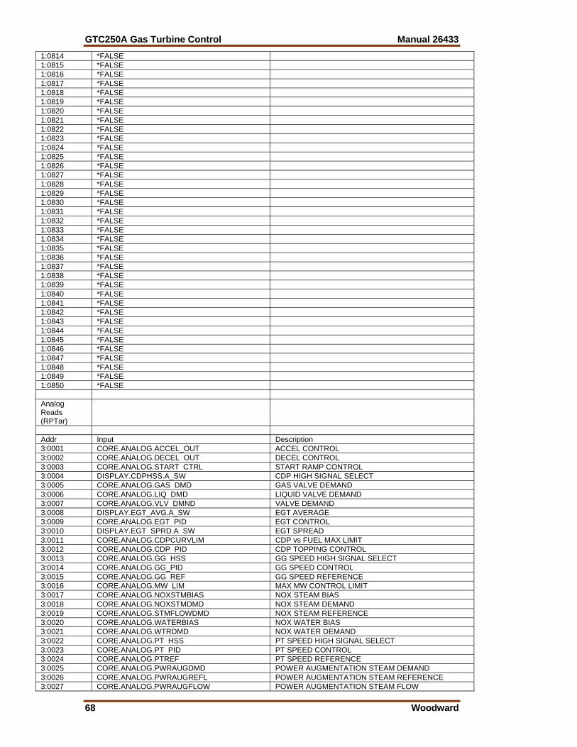
GTC250A Gas Turbine Control Manual 26433
68 Woodward
1:0814 *FALSE 1:0815 *FALSE 1:0816 *FALSE 1:0817 *FALSE 1:0818 *FALSE 1:0819 *FALSE 1:0820 *FALSE 1:0821 *FALSE 1:0822 *FALSE 1:0823 *FALSE 1:0824 *FALSE 1:0825 *FALSE 1:0826 *FALSE 1:0827 *FALSE 1:0828 *FALSE 1:0829 *FALSE 1:0830 *FALSE 1:0831 *FALSE 1:0832 *FALSE 1:0833 *FALSE 1:0834 *FALSE 1:0835 *FALSE 1:0836 *FALSE 1:0837 *FALSE 1:0838 *FALSE 1:0839 *FALSE 1:0840 *FALSE 1:0841 *FALSE 1:0842 *FALSE 1:0843 *FALSE 1:0844 *FALSE 1:0845 *FALSE 1:0846 *FALSE 1:0847 *FALSE 1:0848 *FALSE 1:0849 *FALSE 1:0850 *FALSE Analog Reads (RPTar)
Addr Input Description 3:0001 CORE.ANALOG.ACCEL_OUT ACCEL CONTROL 3:0002 CORE.ANALOG.DECEL OUT DECEL CONTROL 3:0003 CORE.ANALOG.START CTRL START RAMP CONTROL 3:0004 DISPLAY.CDPHSS.A_SW CDP HIGH SIGNAL SELECT 3:0005 CORE.ANALOG.GAS DMD GAS VALVE DEMAND 3:0006 CORE.ANALOG.LIQ DMD LIQUID VALVE DEMAND 3:0007 CORE.ANALOG.VLV DMND VALVE DEMAND 3:0008 DISPLAY.EGT_AVG.A_SW EGT AVERAGE 3:0009 CORE.ANALOG.EGT PID EGT CONTROL 3:0010 DISPLAY.EGT SPRD.A SW EGT SPREAD 3:0011 CORE.ANALOG.CDPCURVLIM CDP vs FUEL MAX LIMIT 3:0012 CORE.ANALOG.CDP PID CDP TOPPING CONTROL 3:0013 CORE.ANALOG.GG HSS GG SPEED HIGH SIGNAL SELECT 3:0014 CORE.ANALOG.GG_PID GG SPEED CONTROL 3:0015 CORE.ANALOG.GG REF GG SPEED REFERENCE 3:0016 CORE.ANALOG.MW LIM MAX MW CONTROL LIMIT 3:0017 CORE.ANALOG.NOXSTMBIAS NOX STEAM BIAS 3:0018 CORE.ANALOG.NOXSTMDMD NOX STEAM DEMAND 3:0019 CORE.ANALOG.STMFLOWDMD NOX STEAM REFERENCE 3:0020 CORE.ANALOG.WATERBIAS NOX WATER BIAS 3:0021 CORE.ANALOG.WTRDMD NOX WATER DEMAND 3:0022 CORE.ANALOG.PT HSS PT SPEED HIGH SIGNAL SELECT 3:0023 CORE.ANALOG.PT PID PT SPEED CONTROL 3:0024 CORE.ANALOG.PTREF PT SPEED REFERENCE 3:0025 CORE.ANALOG.PWRAUGDMD POWER AUGMENTATION STEAM DEMAND 3:0026 CORE.ANALOG.PWRAUGREFL POWER AUGMENTATION STEAM REFERENCE 3:0027 CORE.ANALOG.PWRAUGFLOW POWER AUGMENTATION STEAM FLOW
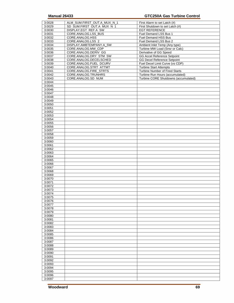
Manual 26433 GTC250A Gas Turbine Control
Woodward 69
3:0028 ALM_SUM.FIRST_OUT.A_MUX_N_1 First Alarm to set Latch (#) 3:0029 SD SUM.FIRST OUT.A MUX N 1 First Shutdown to set Latch (#) 3:0030 DISPLAY.EGT REF.A SW EGT REFERENCE 3:0031 CORE.ANALOG.LSS_BUS Fuel Demand LSS Bus 1 3:0032 CORE.ANALOG.HSS Fuel Demand HSS Bus 3:0033 CORE.ANALOG.LSS 2 Fuel Demand LSS Bus 2 3:0034 DISPLAY.AMBTEMPANY.A_SW Ambient Inlet Temp (Any type) 3:0035 CORE.ANALOG.MW_CDP Turbine MW Load (Snsr or Calc) 3:0036 CORE.ANALOG.DERIV GG Derivative of GG Speed 3:0037 CORE.ANALOG.DRY STM SW GG Accel Reference Setpoint 3:0038 CORE.ANALOG.DECELSCHED GG Decel Reference Setpoint 3:0039 CORE.ANALOG.FUEL DCURV Fuel Decel Limit Curve (vs CDP) 3:0040 CORE.ANALOG.STRT ATTMT Turbine Start Attempts 3:0041 CORE.ANALOG.FIRE_STRTS Turbine Number of Fired Starts 3:0042 CORE.ANALOG.TRUNHRS Turbine Run Hours (accumulated) 3:0043 CORE.ANALOG.SD NUM Turbine CORE Shutdowns (accumulated) 3:0044 3:0045 3:0046 3:0047 3:0048 3:0049 3:0050 3:0051 3:0052 3:0053 3:0054 3:0055 3:0056 3:0057 3:0058 3:0059 3:0060 3:0061 3:0062 3:0063 3:0064 3:0065 3:0066 3:0067 3:0068 3:0069 3:0070 3:0071 3:0072 3:0073 3:0074 3:0075 3:0076 3:0077 3:0078 3:0079 3:0080 3:0081 3:0082 3:0083 3:0084 3:0085 3:0086 3:0087 3:0088 3:0089 3:0090 3:0091 3:0092 3:0093 3:0094 3:0095 3:0096 3:0097
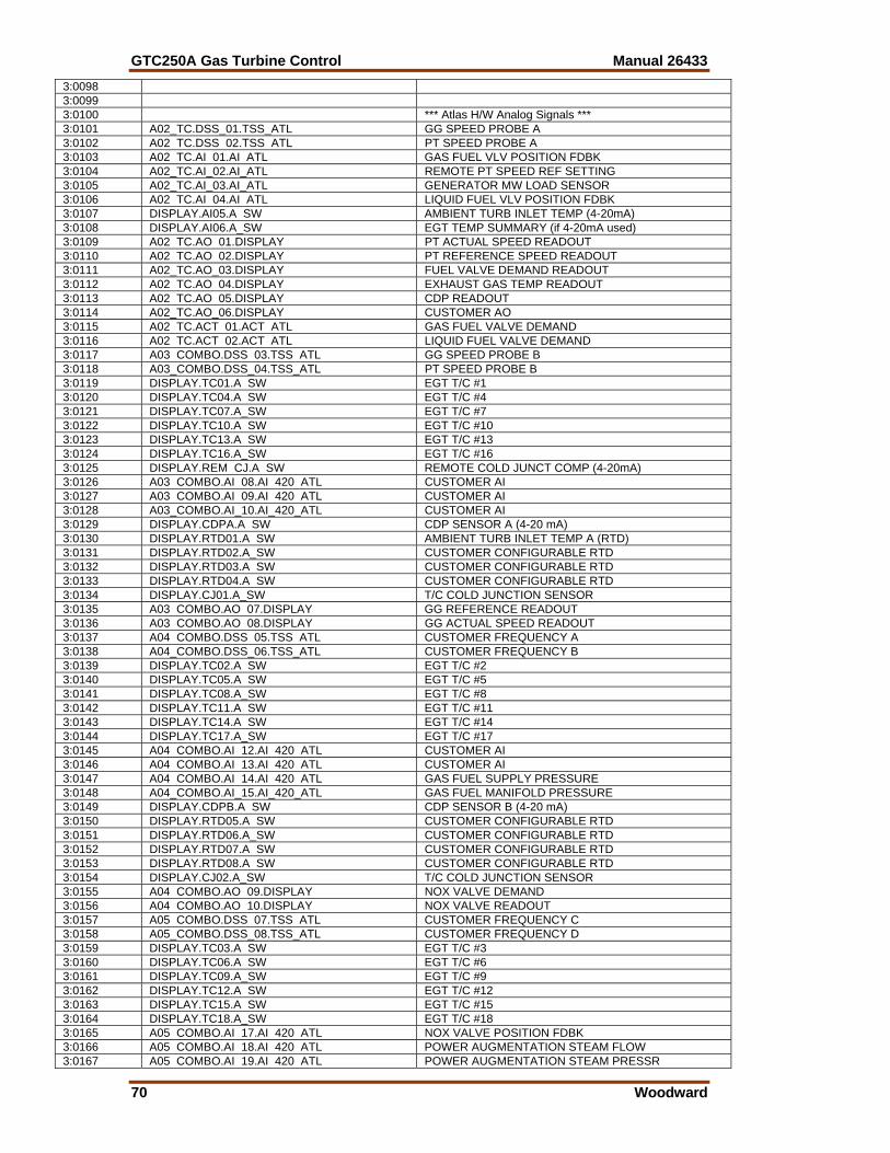
GTC250A Gas Turbine Control Manual 26433
70 Woodward
3:0098 3:0099 3:0100 *** Atlas H/W Analog Signals *** 3:0101 A02_TC.DSS_01.TSS_ATL GG SPEED PROBE A 3:0102 A02 TC.DSS 02.TSS ATL PT SPEED PROBE A 3:0103 A02 TC.AI 01.AI ATL GAS FUEL VLV POSITION FDBK 3:0104 A02_TC.AI_02.AI_ATL REMOTE PT SPEED REF SETTING 3:0105 A02_TC.AI_03.AI_ATL GENERATOR MW LOAD SENSOR 3:0106 A02 TC.AI 04.AI ATL LIQUID FUEL VLV POSITION FDBK 3:0107 DISPLAY.AI05.A SW AMBIENT TURB INLET TEMP (4-20mA) 3:0108 DISPLAY.AI06.A_SW EGT TEMP SUMMARY (if 4-20mA used) 3:0109 A02 TC.AO 01.DISPLAY PT ACTUAL SPEED READOUT 3:0110 A02 TC.AO 02.DISPLAY PT REFERENCE SPEED READOUT 3:0111 A02_TC.AO_03.DISPLAY FUEL VALVE DEMAND READOUT 3:0112 A02 TC.AO 04.DISPLAY EXHAUST GAS TEMP READOUT 3:0113 A02 TC.AO 05.DISPLAY CDP READOUT 3:0114 A02_TC.AO_06.DISPLAY CUSTOMER AO 3:0115 A02 TC.ACT 01.ACT ATL GAS FUEL VALVE DEMAND 3:0116 A02 TC.ACT 02.ACT ATL LIQUID FUEL VALVE DEMAND 3:0117 A03 COMBO.DSS 03.TSS ATL GG SPEED PROBE B 3:0118 A03_COMBO.DSS_04.TSS_ATL PT SPEED PROBE B 3:0119 DISPLAY.TC01.A SW EGT T/C #1 3:0120 DISPLAY.TC04.A SW EGT T/C #4 3:0121 DISPLAY.TC07.A_SW EGT T/C #7 3:0122 DISPLAY.TC10.A SW EGT T/C #10 3:0123 DISPLAY.TC13.A SW EGT T/C #13 3:0124 DISPLAY.TC16.A_SW EGT T/C #16 3:0125 DISPLAY.REM CJ.A SW REMOTE COLD JUNCT COMP (4-20mA) 3:0126 A03 COMBO.AI 08.AI 420 ATL CUSTOMER AI 3:0127 A03 COMBO.AI 09.AI 420 ATL CUSTOMER AI 3:0128 A03_COMBO.AI_10.AI_420_ATL CUSTOMER AI 3:0129 DISPLAY.CDPA.A SW CDP SENSOR A (4-20 mA) 3:0130 DISPLAY.RTD01.A SW AMBIENT TURB INLET TEMP A (RTD) 3:0131 DISPLAY.RTD02.A_SW CUSTOMER CONFIGURABLE RTD 3:0132 DISPLAY.RTD03.A SW CUSTOMER CONFIGURABLE RTD 3:0133 DISPLAY.RTD04.A SW CUSTOMER CONFIGURABLE RTD 3:0134 DISPLAY.CJ01.A_SW T/C COLD JUNCTION SENSOR 3:0135 A03 COMBO.AO 07.DISPLAY GG REFERENCE READOUT 3:0136 A03 COMBO.AO 08.DISPLAY GG ACTUAL SPEED READOUT 3:0137 A04 COMBO.DSS 05.TSS ATL CUSTOMER FREQUENCY A 3:0138 A04_COMBO.DSS_06.TSS_ATL CUSTOMER FREQUENCY B 3:0139 DISPLAY.TC02.A SW EGT T/C #2 3:0140 DISPLAY.TC05.A SW EGT T/C #5 3:0141 DISPLAY.TC08.A_SW EGT T/C #8 3:0142 DISPLAY.TC11.A SW EGT T/C #11 3:0143 DISPLAY.TC14.A SW EGT T/C #14 3:0144 DISPLAY.TC17.A_SW EGT T/C #17 3:0145 A04 COMBO.AI 12.AI 420 ATL CUSTOMER AI 3:0146 A04 COMBO.AI 13.AI 420 ATL CUSTOMER AI 3:0147 A04 COMBO.AI 14.AI 420 ATL GAS FUEL SUPPLY PRESSURE 3:0148 A04_COMBO.AI_15.AI_420_ATL GAS FUEL MANIFOLD PRESSURE 3:0149 DISPLAY.CDPB.A SW CDP SENSOR B (4-20 mA) 3:0150 DISPLAY.RTD05.A SW CUSTOMER CONFIGURABLE RTD 3:0151 DISPLAY.RTD06.A_SW CUSTOMER CONFIGURABLE RTD 3:0152 DISPLAY.RTD07.A SW CUSTOMER CONFIGURABLE RTD 3:0153 DISPLAY.RTD08.A SW CUSTOMER CONFIGURABLE RTD 3:0154 DISPLAY.CJ02.A_SW T/C COLD JUNCTION SENSOR 3:0155 A04 COMBO.AO 09.DISPLAY NOX VALVE DEMAND 3:0156 A04 COMBO.AO 10.DISPLAY NOX VALVE READOUT 3:0157 A05 COMBO.DSS 07.TSS ATL CUSTOMER FREQUENCY C 3:0158 A05_COMBO.DSS_08.TSS_ATL CUSTOMER FREQUENCY D 3:0159 DISPLAY.TC03.A SW EGT T/C #3 3:0160 DISPLAY.TC06.A SW EGT T/C #6 3:0161 DISPLAY.TC09.A_SW EGT T/C #9 3:0162 DISPLAY.TC12.A SW EGT T/C #12 3:0163 DISPLAY.TC15.A SW EGT T/C #15 3:0164 DISPLAY.TC18.A_SW EGT T/C #18 3:0165 A05 COMBO.AI 17.AI 420 ATL NOX VALVE POSITION FDBK 3:0166 A05 COMBO.AI 18.AI 420 ATL POWER AUGMENTATION STEAM FLOW 3:0167 A05 COMBO.AI 19.AI 420 ATL POWER AUGMENTATION STEAM PRESSR
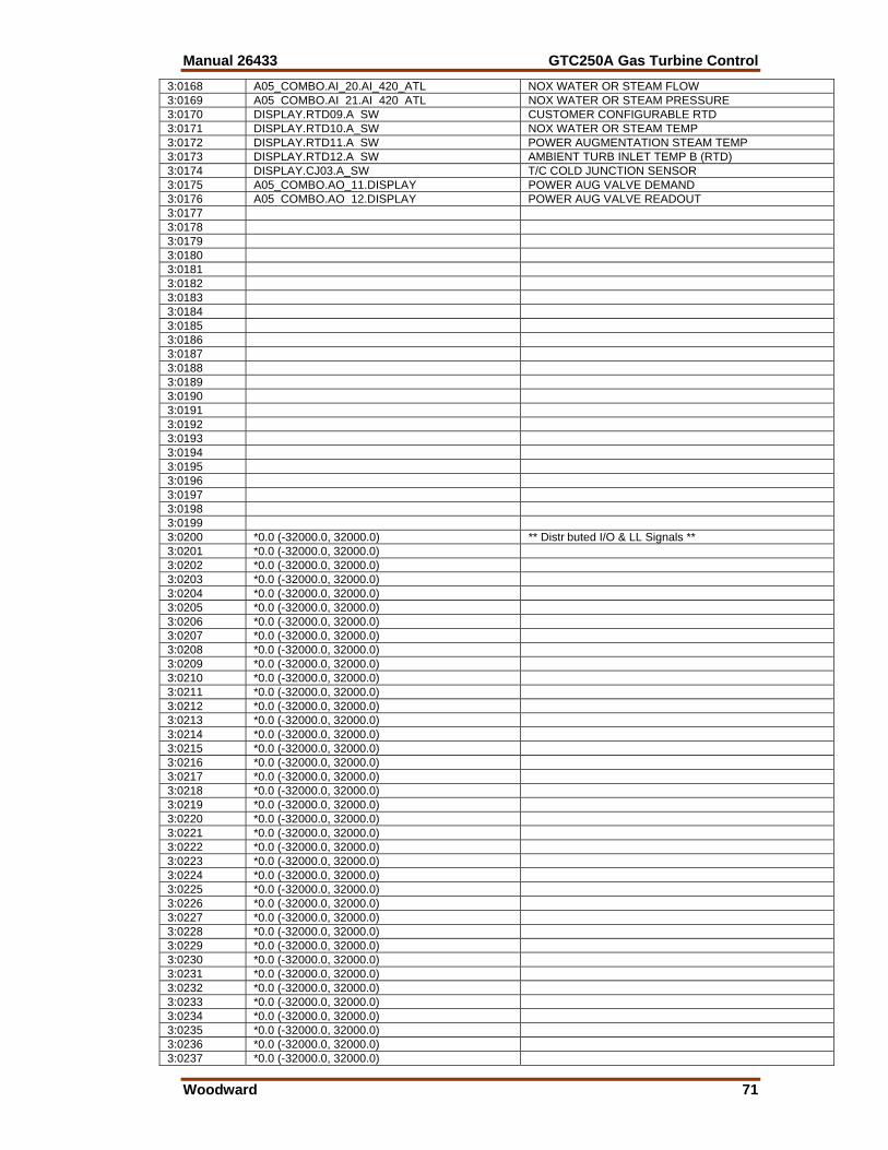
Manual 26433 GTC250A Gas Turbine Control
Woodward 71
3:0168 A05_COMBO.AI_20.AI_420_ATL NOX WATER OR STEAM FLOW 3:0169 A05 COMBO.AI 21.AI 420 ATL NOX WATER OR STEAM PRESSURE 3:0170 DISPLAY.RTD09.A SW CUSTOMER CONFIGURABLE RTD 3:0171 DISPLAY.RTD10.A_SW NOX WATER OR STEAM TEMP 3:0172 DISPLAY.RTD11.A SW POWER AUGMENTATION STEAM TEMP 3:0173 DISPLAY.RTD12.A SW AMBIENT TURB INLET TEMP B (RTD) 3:0174 DISPLAY.CJ03.A_SW T/C COLD JUNCTION SENSOR 3:0175 A05_COMBO.AO_11.DISPLAY POWER AUG VALVE DEMAND 3:0176 A05 COMBO.AO 12.DISPLAY POWER AUG VALVE READOUT 3:0177 3:0178 3:0179 3:0180 3:0181 3:0182 3:0183 3:0184 3:0185 3:0186 3:0187 3:0188 3:0189 3:0190 3:0191 3:0192 3:0193 3:0194 3:0195 3:0196 3:0197 3:0198 3:0199 3:0200 *0.0 (-32000.0, 32000.0) ** Distr buted I/O & LL Signals ** 3:0201 *0.0 (-32000.0, 32000.0) 3:0202 *0.0 (-32000.0, 32000.0) 3:0203 *0.0 (-32000.0, 32000.0) 3:0204 *0.0 (-32000.0, 32000.0) 3:0205 *0.0 (-32000.0, 32000.0) 3:0206 *0.0 (-32000.0, 32000.0) 3:0207 *0.0 (-32000.0, 32000.0) 3:0208 *0.0 (-32000.0, 32000.0) 3:0209 *0.0 (-32000.0, 32000.0) 3:0210 *0.0 (-32000.0, 32000.0) 3:0211 *0.0 (-32000.0, 32000.0) 3:0212 *0.0 (-32000.0, 32000.0) 3:0213 *0.0 (-32000.0, 32000.0) 3:0214 *0.0 (-32000.0, 32000.0) 3:0215 *0.0 (-32000.0, 32000.0) 3:0216 *0.0 (-32000.0, 32000.0) 3:0217 *0.0 (-32000.0, 32000.0) 3:0218 *0.0 (-32000.0, 32000.0) 3:0219 *0.0 (-32000.0, 32000.0) 3:0220 *0.0 (-32000.0, 32000.0) 3:0221 *0.0 (-32000.0, 32000.0) 3:0222 *0.0 (-32000.0, 32000.0) 3:0223 *0.0 (-32000.0, 32000.0) 3:0224 *0.0 (-32000.0, 32000.0) 3:0225 *0.0 (-32000.0, 32000.0) 3:0226 *0.0 (-32000.0, 32000.0) 3:0227 *0.0 (-32000.0, 32000.0) 3:0228 *0.0 (-32000.0, 32000.0) 3:0229 *0.0 (-32000.0, 32000.0) 3:0230 *0.0 (-32000.0, 32000.0) 3:0231 *0.0 (-32000.0, 32000.0) 3:0232 *0.0 (-32000.0, 32000.0) 3:0233 *0.0 (-32000.0, 32000.0) 3:0234 *0.0 (-32000.0, 32000.0) 3:0235 *0.0 (-32000.0, 32000.0) 3:0236 *0.0 (-32000.0, 32000.0) 3:0237 *0.0 (-32000.0, 32000.0)
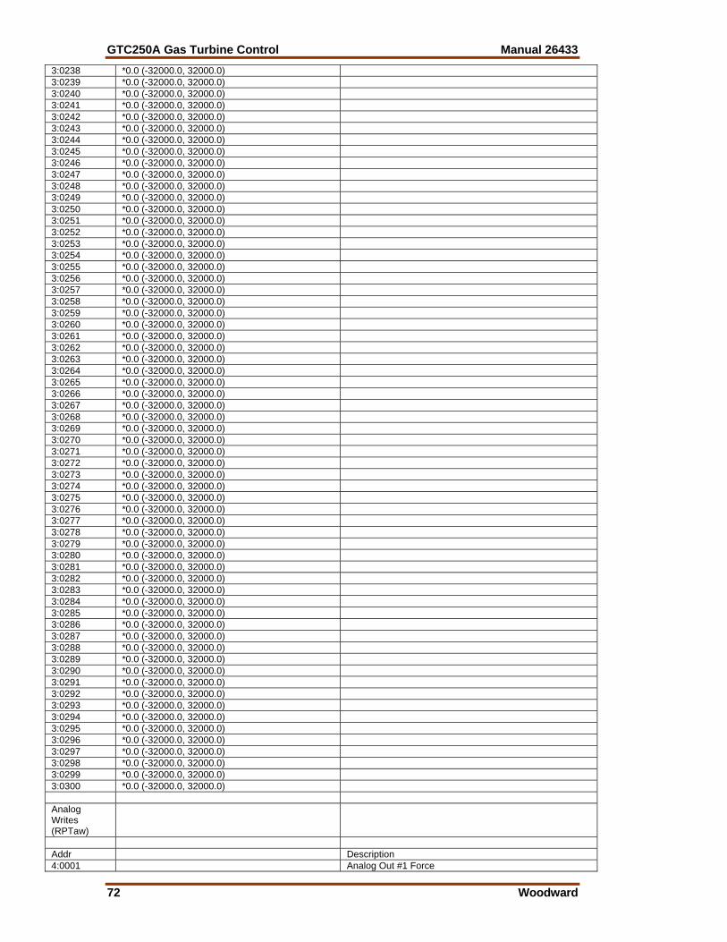
GTC250A Gas Turbine Control Manual 26433
72 Woodward
3:0238 *0.0 (-32000.0, 32000.0) 3:0239 *0.0 (-32000.0, 32000.0) 3:0240 *0.0 (-32000.0, 32000.0) 3:0241 *0.0 (-32000.0, 32000.0) 3:0242 *0.0 (-32000.0, 32000.0) 3:0243 *0.0 (-32000.0, 32000.0) 3:0244 *0.0 (-32000.0, 32000.0) 3:0245 *0.0 (-32000.0, 32000.0) 3:0246 *0.0 (-32000.0, 32000.0) 3:0247 *0.0 (-32000.0, 32000.0) 3:0248 *0.0 (-32000.0, 32000.0) 3:0249 *0.0 (-32000.0, 32000.0) 3:0250 *0.0 (-32000.0, 32000.0) 3:0251 *0.0 (-32000.0, 32000.0) 3:0252 *0.0 (-32000.0, 32000.0) 3:0253 *0.0 (-32000.0, 32000.0) 3:0254 *0.0 (-32000.0, 32000.0) 3:0255 *0.0 (-32000.0, 32000.0) 3:0256 *0.0 (-32000.0, 32000.0) 3:0257 *0.0 (-32000.0, 32000.0) 3:0258 *0.0 (-32000.0, 32000.0) 3:0259 *0.0 (-32000.0, 32000.0) 3:0260 *0.0 (-32000.0, 32000.0) 3:0261 *0.0 (-32000.0, 32000.0) 3:0262 *0.0 (-32000.0, 32000.0) 3:0263 *0.0 (-32000.0, 32000.0) 3:0264 *0.0 (-32000.0, 32000.0) 3:0265 *0.0 (-32000.0, 32000.0) 3:0266 *0.0 (-32000.0, 32000.0) 3:0267 *0.0 (-32000.0, 32000.0) 3:0268 *0.0 (-32000.0, 32000.0) 3:0269 *0.0 (-32000.0, 32000.0) 3:0270 *0.0 (-32000.0, 32000.0) 3:0271 *0.0 (-32000.0, 32000.0) 3:0272 *0.0 (-32000.0, 32000.0) 3:0273 *0.0 (-32000.0, 32000.0) 3:0274 *0.0 (-32000.0, 32000.0) 3:0275 *0.0 (-32000.0, 32000.0) 3:0276 *0.0 (-32000.0, 32000.0) 3:0277 *0.0 (-32000.0, 32000.0) 3:0278 *0.0 (-32000.0, 32000.0) 3:0279 *0.0 (-32000.0, 32000.0) 3:0280 *0.0 (-32000.0, 32000.0) 3:0281 *0.0 (-32000.0, 32000.0) 3:0282 *0.0 (-32000.0, 32000.0) 3:0283 *0.0 (-32000.0, 32000.0) 3:0284 *0.0 (-32000.0, 32000.0) 3:0285 *0.0 (-32000.0, 32000.0) 3:0286 *0.0 (-32000.0, 32000.0) 3:0287 *0.0 (-32000.0, 32000.0) 3:0288 *0.0 (-32000.0, 32000.0) 3:0289 *0.0 (-32000.0, 32000.0) 3:0290 *0.0 (-32000.0, 32000.0) 3:0291 *0.0 (-32000.0, 32000.0) 3:0292 *0.0 (-32000.0, 32000.0) 3:0293 *0.0 (-32000.0, 32000.0) 3:0294 *0.0 (-32000.0, 32000.0) 3:0295 *0.0 (-32000.0, 32000.0) 3:0296 *0.0 (-32000.0, 32000.0) 3:0297 *0.0 (-32000.0, 32000.0) 3:0298 *0.0 (-32000.0, 32000.0) 3:0299 *0.0 (-32000.0, 32000.0) 3:0300 *0.0 (-32000.0, 32000.0) Analog Writes (RPTaw)
Addr Description 4:0001 Analog Out #1 Force
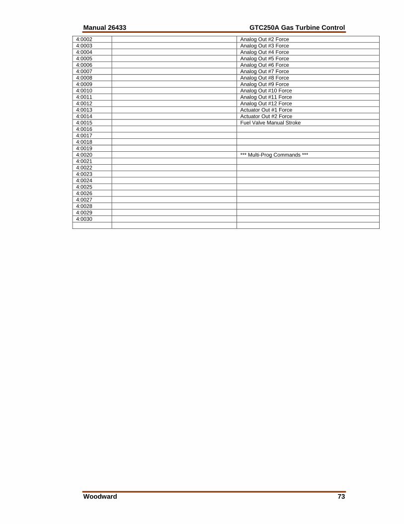
Manual 26433 GTC250A Gas Turbine Control
Woodward 73
4:0002 Analog Out #2 Force 4:0003 Analog Out #3 Force 4:0004 Analog Out #4 Force 4:0005 Analog Out #5 Force 4:0006 Analog Out #6 Force 4:0007 Analog Out #7 Force 4:0008 Analog Out #8 Force 4:0009 Analog Out #9 Force 4:0010 Analog Out #10 Force 4:0011 Analog Out #11 Force 4:0012 Analog Out #12 Force 4:0013 Actuator Out #1 Force 4:0014 Actuator Out #2 Force 4:0015 Fuel Valve Manual Stroke 4:0016 4:0017 4:0018 4:0019 4:0020 *** Multi-Prog Commands *** 4:0021 4:0022 4:0023 4:0024 4:0025 4:0026 4:0027 4:0028 4:0029 4:0030
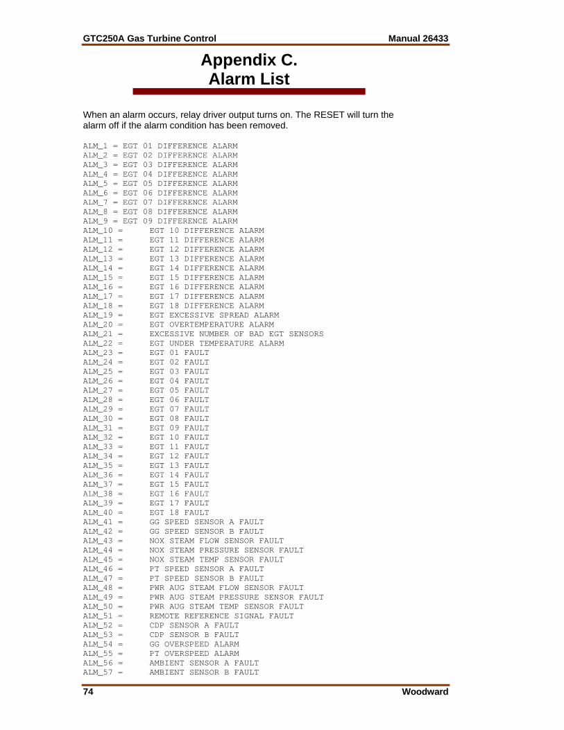
GTC250A Gas Turbine Control Manual 26433
74 Woodward
Appendix C. Alarm List
When an alarm occurs, relay driver output turns on. The RESET will turn the alarm off if the alarm condition has been removed. ALM_1 = EGT 01 DIFFERENCE ALARM ALM_2 = EGT 02 DIFFERENCE ALARM ALM_3 = EGT 03 DIFFERENCE ALARM ALM_4 = EGT 04 DIFFERENCE ALARM ALM_5 = EGT 05 DIFFERENCE ALARM ALM_6 = EGT 06 DIFFERENCE ALARM ALM_7 = EGT 07 DIFFERENCE ALARM ALM_8 = EGT 08 DIFFERENCE ALARM ALM_9 = EGT 09 DIFFERENCE ALARM ALM_10 = EGT 10 DIFFERENCE ALARM ALM_11 = EGT 11 DIFFERENCE ALARM ALM_12 = EGT 12 DIFFERENCE ALARM ALM_13 = EGT 13 DIFFERENCE ALARM ALM_14 = EGT 14 DIFFERENCE ALARM ALM_15 = EGT 15 DIFFERENCE ALARM ALM_16 = EGT 16 DIFFERENCE ALARM ALM_17 = EGT 17 DIFFERENCE ALARM ALM_18 = EGT 18 DIFFERENCE ALARM ALM_19 = EGT EXCESSIVE SPREAD ALARM ALM_20 = EGT OVERTEMPERATURE ALARM ALM_21 = EXCESSIVE NUMBER OF BAD EGT SENSORS ALM_22 = EGT UNDER TEMPERATURE ALARM ALM_23 = EGT 01 FAULT ALM_24 = EGT 02 FAULT ALM_25 = EGT 03 FAULT ALM_26 = EGT 04 FAULT ALM_27 = EGT 05 FAULT ALM_28 = EGT 06 FAULT ALM_29 = EGT 07 FAULT ALM_30 = EGT 08 FAULT ALM_31 = EGT 09 FAULT ALM_32 = EGT 10 FAULT ALM_33 = EGT 11 FAULT ALM_34 = EGT 12 FAULT ALM_35 = EGT 13 FAULT ALM_36 = EGT 14 FAULT ALM_37 = EGT 15 FAULT ALM_38 = EGT 16 FAULT ALM_39 = EGT 17 FAULT ALM_40 = EGT 18 FAULT ALM_41 = GG SPEED SENSOR A FAULT ALM_42 = GG SPEED SENSOR B FAULT ALM_43 = NOX STEAM FLOW SENSOR FAULT ALM_44 = NOX STEAM PRESSURE SENSOR FAULT ALM_45 = NOX STEAM TEMP SENSOR FAULT ALM_46 = PT SPEED SENSOR A FAULT ALM_47 = PT SPEED SENSOR B FAULT ALM_48 = PWR AUG STEAM FLOW SENSOR FAULT ALM_49 = PWR AUG STEAM PRESSURE SENSOR FAULT ALM_50 = PWR AUG STEAM TEMP SENSOR FAULT ALM_51 = REMOTE REFERENCE SIGNAL FAULT ALM_52 = CDP SENSOR A FAULT ALM_53 = CDP SENSOR B FAULT ALM_54 = GG OVERSPEED ALARM ALM_55 = PT OVERSPEED ALARM ALM_56 = AMBIENT SENSOR A FAULT ALM_57 = AMBIENT SENSOR B FAULT
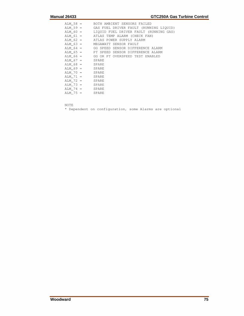
Manual 26433 GTC250A Gas Turbine Control
Woodward 75
ALM_58 = BOTH AMBIENT SENSORS FAILED ALM_59 = GAS FUEL DRIVER FAULT (RUNNING LIQUID) ALM_60 = LIQUID FUEL DRIVER FAULT (RUNNING GAS) ALM_61 = ATLAS TEMP ALARM (CHECK FAN) ALM_62 = ATLAS POWER SUPPLY ALARM ALM_63 = MEGAWATT SENSOR FAULT ALM_64 = GG SPEED SENSOR DIFFERENCE ALARM ALM_65 = PT SPEED SENSOR DIFFERENCE ALARM ALM_66 = GG OR PT OVERSPEED TEST ENABLED ALM_67 = SPARE ALM_68 = SPARE ALM_69 = SPARE ALM_70 = SPARE ALM_71 = SPARE ALM_72 = SPARE ALM_73 = SPARE ALM_74 = SPARE ALM_75 = SPARE NOTE * Dependent on configuration, some Alarms are optional
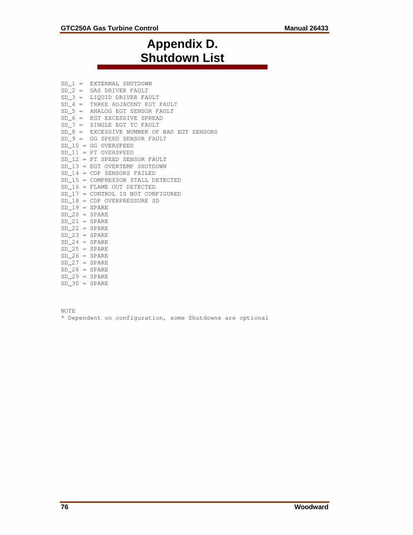
GTC250A Gas Turbine Control Manual 26433
76 Woodward
Appendix D. Shutdown List
SD_1 = EXTERNAL SHUTDOWN SD_2 = GAS DRIVER FAULT SD_3 = LIQUID DRIVER FAULT SD_4 = THREE ADJACENT EGT FAULT SD_5 = ANALOG EGT SENSOR FAULT SD_6 = EGT EXCESSIVE SPREAD SD_7 = SINGLE EGT TC FAULT SD_8 = EXCESSIVE NUMBER OF BAD EGT SENSORS SD_9 = GG SPEED SENSOR FAULT SD_10 = GG OVERSPEED SD_11 = PT OVERSPEED SD_12 = PT SPEED SENSOR FAULT SD_13 = EGT OVERTEMP SHUTDOWN SD_14 = CDP SENSORS FAILED SD_15 = COMPRESSOR STALL DETECTED SD_16 = FLAME OUT DETECTED SD_17 = CONTROL IS NOT CONFIGURED SD_18 = CDP OVERPRESSURE SD SD_19 = SPARE SD_20 = SPARE SD_21 = SPARE SD_22 = SPARE SD_23 = SPARE SD_24 = SPARE SD_25 = SPARE SD_26 = SPARE SD_27 = SPARE SD_28 = SPARE SD_29 = SPARE SD_30 = SPARE NOTE * Dependent on configuration, some Shutdowns are optional
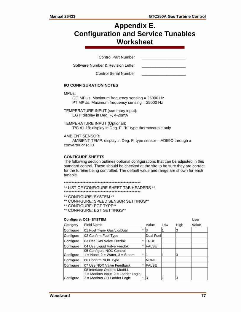
Manual 26433 GTC250A Gas Turbine Control
Woodward 77
Appendix E. Configuration and Service Tunables
Worksheet Control Part Number ____________________ Software Number & Revision Letter ____________________ Control Serial Number ____________________ I/O CONFIGURATION NOTES MPUs: GG MPUs: Maximum frequency sensing = 25000 Hz PT MPUs: Maximum frequency sensing = 25000 Hz TEMPERATURE INPUT (summary input): EGT: display in Deg. F, 4-20mA TEMPERATURE INPUT (Optional): T/C #1-18: display in Deg. F, "K" type thermocouple only AMBIENT SENSOR: AMBIENT TEMP: display in Deg. F, type sensor = AD59O through a converter or RTD CONFIGURE SHEETS The following section outlines optional configurations that can be adjusted in this standard control. These should be checked at the site to be sure they are correct for the turbine being controlled. The default value and range are shown for each tunable. ************************************************** ** LIST OF CONFIGURE SHEET TAB HEADERS ** ************************************************** ** CONFIGURE: SYSTEM ** ** CONFIGURE: SPEED SENSOR SETTINGS** ** CONFIGURE: EGT TYPE** ** CONFIGURE: EGT SETTINGS** Configure: C01- SYSTEM User Category Field Name Value Low High Value Configure 01 Fuel Type- Gas/Liq/Dual * 3 1 3 Configure 02 Confirm Fuel Type Dual Fuel Configure 03 Use Gas Valve Feedbk * TRUE Configure 04 Use Liquid Valve Feedbk * FALSE
Configure 05 Configure NOX Control 1 = None, 2 = Water, 3 = Steam * 1 1 3
Configure 06 Confirm NOX Type NONE Configure 07 Use NOX Valve Feedback * FALSE
Configure
08 Interface Options Mod/LL 1 = Modbus Input, 2 = Ladder Logic, 3 = Modbus OR Ladder Logic * 3 1 3
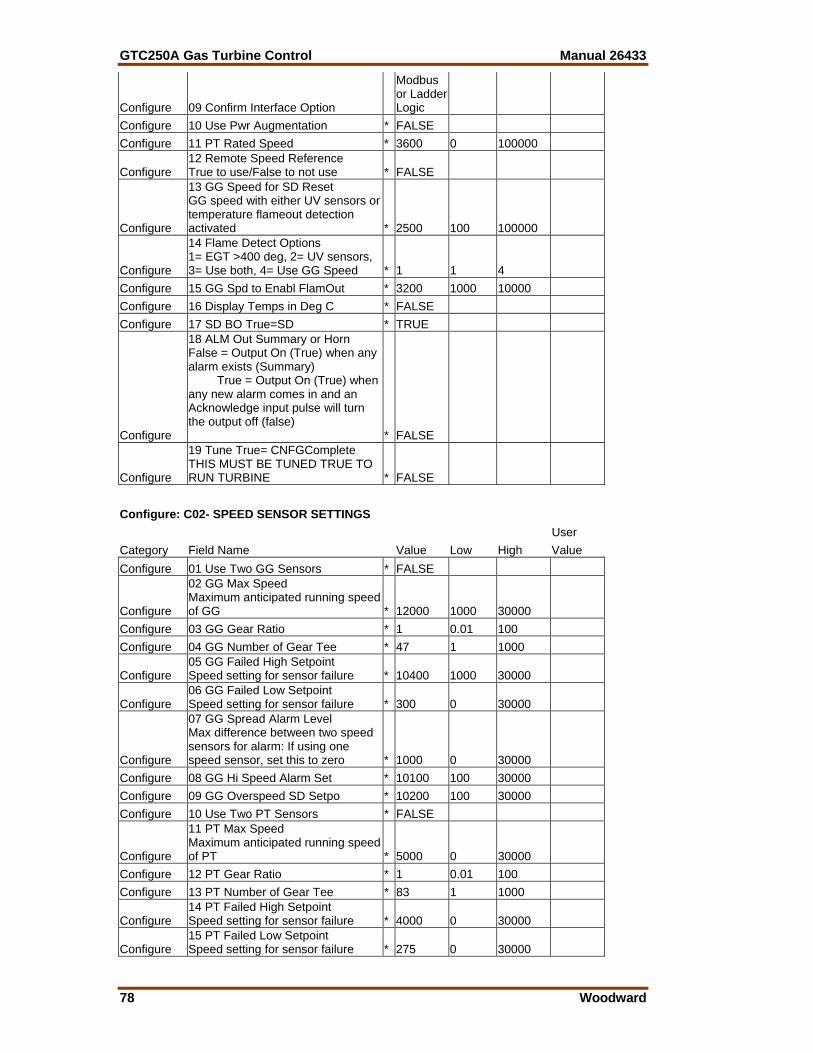
GTC250A Gas Turbine Control Manual 26433
78 Woodward
Configure 09 Confirm Interface Option
Modbus or Ladder Logic
Configure 10 Use Pwr Augmentation * FALSE Configure 11 PT Rated Speed * 3600 0 100000
Configure 12 Remote Speed Reference True to use/False to not use * FALSE
Configure
13 GG Speed for SD Reset GG speed with either UV sensors or temperature flameout detection activated * 2500 100 100000
Configure
14 Flame Detect Options 1= EGT >400 deg, 2= UV sensors, 3= Use both, 4= Use GG Speed * 1 1 4
Configure 15 GG Spd to Enabl FlamOut * 3200 1000 10000 Configure 16 Display Temps in Deg C * FALSE Configure 17 SD BO True=SD * TRUE
Configure
18 ALM Out Summary or Horn False = Output On (True) when any alarm exists (Summary) True = Output On (True) when any new alarm comes in and an Acknowledge input pulse will turn the output off (false) * FALSE
Configure
19 Tune True= CNFGComplete THIS MUST BE TUNED TRUE TO RUN TURBINE * FALSE
Configure: C02- SPEED SENSOR SETTINGS User Category Field Name Value Low High Value Configure 01 Use Two GG Sensors * FALSE
Configure
02 GG Max Speed Maximum anticipated running speed of GG * 12000 1000 30000
Configure 03 GG Gear Ratio * 1 0.01 100 Configure 04 GG Number of Gear Tee * 47 1 1000
Configure 05 GG Failed High Setpoint Speed setting for sensor failure * 10400 1000 30000
Configure 06 GG Failed Low Setpoint Speed setting for sensor failure * 300 0 30000
Configure
07 GG Spread Alarm Level Max difference between two speed sensors for alarm: If using one speed sensor, set this to zero * 1000 0 30000
Configure 08 GG Hi Speed Alarm Set * 10100 100 30000 Configure 09 GG Overspeed SD Setpo * 10200 100 30000 Configure 10 Use Two PT Sensors * FALSE
Configure
11 PT Max Speed Maximum anticipated running speed of PT * 5000 0 30000
Configure 12 PT Gear Ratio * 1 0.01 100 Configure 13 PT Number of Gear Tee * 83 1 1000
Configure 14 PT Failed High Setpoint Speed setting for sensor failure * 4000 0 30000
Configure 15 PT Failed Low Setpoint Speed setting for sensor failure * 275 0 30000
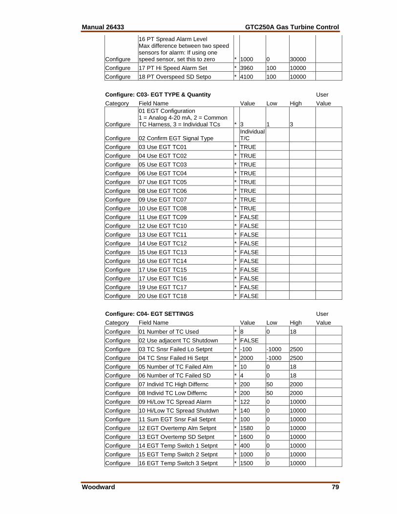
Manual 26433 GTC250A Gas Turbine Control
Woodward 79
Configure
16 PT Spread Alarm Level Max difference between two speed sensors for alarm: If using one speed sensor, set this to zero * 1000 0 30000
Configure 17 PT Hi Speed Alarm Set * 3960 100 10000 Configure 18 PT Overspeed SD Setpo * 4100 100 10000 Configure: C03- EGT TYPE & Quantity User Category Field Name Value Low High Value
Configure
01 EGT Configuration 1 = Analog 4-20 mA, 2 = Common TC Harness, 3 = Individual TCs * 3 1 3
Configure 02 Confirm EGT Signal Type Individual T/C
Configure 03 Use EGT TC01 * TRUE Configure 04 Use EGT TC02 * TRUE Configure 05 Use EGT TC03 * TRUE Configure 06 Use EGT TC04 * TRUE Configure 07 Use EGT TC05 * TRUE Configure 08 Use EGT TC06 * TRUE Configure 09 Use EGT TC07 * TRUE Configure 10 Use EGT TC08 * TRUE Configure 11 Use EGT TC09 * FALSE Configure 12 Use EGT TC10 * FALSE Configure 13 Use EGT TC11 * FALSE Configure 14 Use EGT TC12 * FALSE Configure 15 Use EGT TC13 * FALSE Configure 16 Use EGT TC14 * FALSE Configure 17 Use EGT TC15 * FALSE Configure 17 Use EGT TC16 * FALSE Configure 19 Use EGT TC17 * FALSE Configure 20 Use EGT TC18 * FALSE Configure: C04- EGT SETTINGS User Category Field Name Value Low High Value Configure 01 Number of TC Used * 8 0 18 Configure 02 Use adjacent TC Shutdown * FALSE Configure 03 TC Snsr Failed Lo Setpnt * -100 -1000 2500 Configure 04 TC Snsr Failed Hi Setpt * 2000 -1000 2500 Configure 05 Number of TC Failed Alm * 10 0 18 Configure 06 Number of TC Failed SD * 4 0 18 Configure 07 Individ TC High Differnc * 200 50 2000 Configure 08 Individ TC Low Differnc * 200 50 2000 Configure 09 Hi/Low TC Spread Alarm * 122 0 10000 Configure 10 Hi/Low TC Spread Shutdwn * 140 0 10000 Configure 11 Sum EGT Snsr Fail Setpnt * 100 0 10000 Configure 12 EGT Overtemp Alm Setpnt * 1580 0 10000 Configure 13 EGT Overtemp SD Setpnt * 1600 0 10000 Configure 14 EGT Temp Switch 1 Setpnt * 400 0 10000 Configure 15 EGT Temp Switch 2 Setpnt * 1000 0 10000 Configure 16 EGT Temp Switch 3 Setpnt * 1500 0 10000
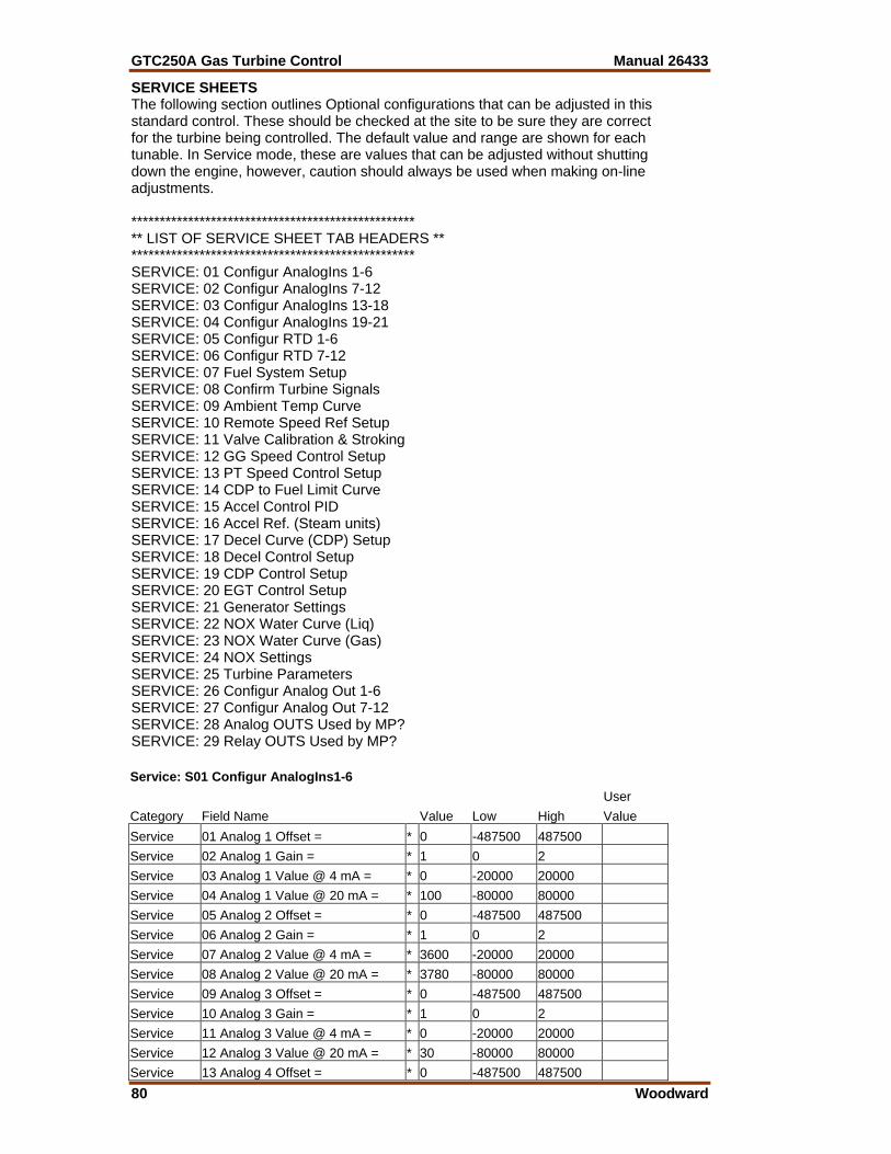
GTC250A Gas Turbine Control Manual 26433
80 Woodward
SERVICE SHEETS The following section outlines Optional configurations that can be adjusted in this standard control. These should be checked at the site to be sure they are correct for the turbine being controlled. The default value and range are shown for each tunable. In Service mode, these are values that can be adjusted without shutting down the engine, however, caution should always be used when making on-line adjustments. ************************************************** ** LIST OF SERVICE SHEET TAB HEADERS ** ************************************************** SERVICE: 01 Configur AnalogIns 1-6 SERVICE: 02 Configur AnalogIns 7-12 SERVICE: 03 Configur AnalogIns 13-18 SERVICE: 04 Configur AnalogIns 19-21 SERVICE: 05 Configur RTD 1-6 SERVICE: 06 Configur RTD 7-12 SERVICE: 07 Fuel System Setup SERVICE: 08 Confirm Turbine Signals SERVICE: 09 Ambient Temp Curve SERVICE: 10 Remote Speed Ref Setup SERVICE: 11 Valve Calibration & Stroking SERVICE: 12 GG Speed Control Setup SERVICE: 13 PT Speed Control Setup SERVICE: 14 CDP to Fuel Limit Curve SERVICE: 15 Accel Control PID SERVICE: 16 Accel Ref. (Steam units) SERVICE: 17 Decel Curve (CDP) Setup SERVICE: 18 Decel Control Setup SERVICE: 19 CDP Control Setup SERVICE: 20 EGT Control Setup SERVICE: 21 Generator Settings SERVICE: 22 NOX Water Curve (Liq) SERVICE: 23 NOX Water Curve (Gas) SERVICE: 24 NOX Settings SERVICE: 25 Turbine Parameters SERVICE: 26 Configur Analog Out 1-6 SERVICE: 27 Configur Analog Out 7-12 SERVICE: 28 Analog OUTS Used by MP? SERVICE: 29 Relay OUTS Used by MP? Service: S01 Configur AnalogIns1-6 User Category Field Name Value Low High Value Service 01 Analog 1 Offset = * 0 -487500 487500 Service 02 Analog 1 Gain = * 1 0 2 Service 03 Analog 1 Value @ 4 mA = * 0 -20000 20000 Service 04 Analog 1 Value @ 20 mA = * 100 -80000 80000 Service 05 Analog 2 Offset = * 0 -487500 487500 Service 06 Analog 2 Gain = * 1 0 2 Service 07 Analog 2 Value @ 4 mA = * 3600 -20000 20000 Service 08 Analog 2 Value @ 20 mA = * 3780 -80000 80000 Service 09 Analog 3 Offset = * 0 -487500 487500 Service 10 Analog 3 Gain = * 1 0 2 Service 11 Analog 3 Value @ 4 mA = * 0 -20000 20000 Service 12 Analog 3 Value @ 20 mA = * 30 -80000 80000 Service 13 Analog 4 Offset = * 0 -487500 487500
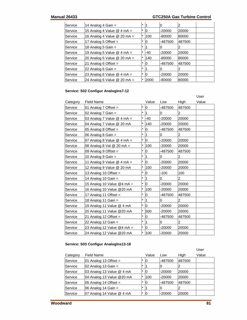
Manual 26433 GTC250A Gas Turbine Control
Woodward 81
Service 14 Analog 4 Gain = * 1 0 2 Service 15 Analog 4 Value @ 4 mA = * 0 -20000 20000 Service 16 Analog 4 Value @ 20 mA = * 100 -80000 80000 Service 17 Analog 5 Offset = * 0 -487500 487500 Service 18 Analog 5 Gain = * 1 0 2 Service 19 Analog 5 Value @ 4 mA = * -40 -20000 20000 Service 20 Analog 5 Value @ 20 mA = * 140 -80000 80000 Service 21 Analog 6 Offset = * 0 -487500 487500 Service 22 Analog 6 Gain = * 1 0 2 Service 23 Analog 6 Value @ 4 mA = * 0 -20000 20000 Service 24 Analog 6 Value @ 20 mA = * 2000 -80000 80000 Service: S02 Configur AnalogIns7-12 User Category Field Name Value Low High Value Service 01 Analog 7 Offset = * 0 -487500 487500 Service 02 Analog 7 Gain = * 1 0 2 Service 03 Analog 7 Value @ 4 mA = * -40 -20000 20000 Service 04 Analog 7 Value @ 20 mA * 140 -20000 20000 Service 05 Analog 8 Offset = * 0 -487500 487500 Service 06 Analog 8 Gain = * 1 0 2 Service 07 Analog 8 Value @ 4 mA = * 0 -20000 20000 Service 08 Analog 8 Val @ 20 mA = * 100 -20000 20000 Service 09 Analog 9 Offset = * 0 -487500 487500 Service 10 Analog 9 Gain = * 1 0 2 Service 11 Analog 9 Value @ 4 mA = * 0 -20000 20000 Service 12 Analog 9 Value @ 20 mA * 100 -20000 20000 Service 13 Analog 10 Offset = * 0 -100 100 Service 14 Analog 10 Gain = * 1 0 2 Service 15 Analog 10 Value @4 mA = * 0 -20000 20000 Service 16 Analog 10 Value @20 mA * 100 -20000 20000 Service 17 Analog 11 Offset = * 0 -487500 487500 Service 18 Analog 11 Gain = * 1 0 2 Service 19 Analog 11 Value @ 4 mA * 0 -20000 20000 Service 20 Analog 11 Value @20 mA * 500 -20000 20000 Service 21 Analog 12 Offset = * 0 -487500 487500 Service 22 Analog 12 Gain = * 1 0 2 Service 23 Analog 12 Value @4 mA = * 0 -20000 20000 Service 24 Analog 12 Value @20 mA * 100 -20000 20000 Service: S03 Configur AnalogIns13-18 User Category Field Name Value Low High Value Service 01 Analog 13 Offset = * 0 -487500 487500 Service 02 Analog 13 Gain = * 1 0 2 Service 03 Analog 13 Value @ 4 mA * 0 -20000 20000 Service 04 Analog 13 Value @20 mA * 100 -20000 20000 Service 05 Analog 14 Offset = * 0 -487500 487500 Service 06 Analog 14 Gain = * 1 0 2 Service 07 Analog 14 Value @ 4 mA * 0 -20000 20000
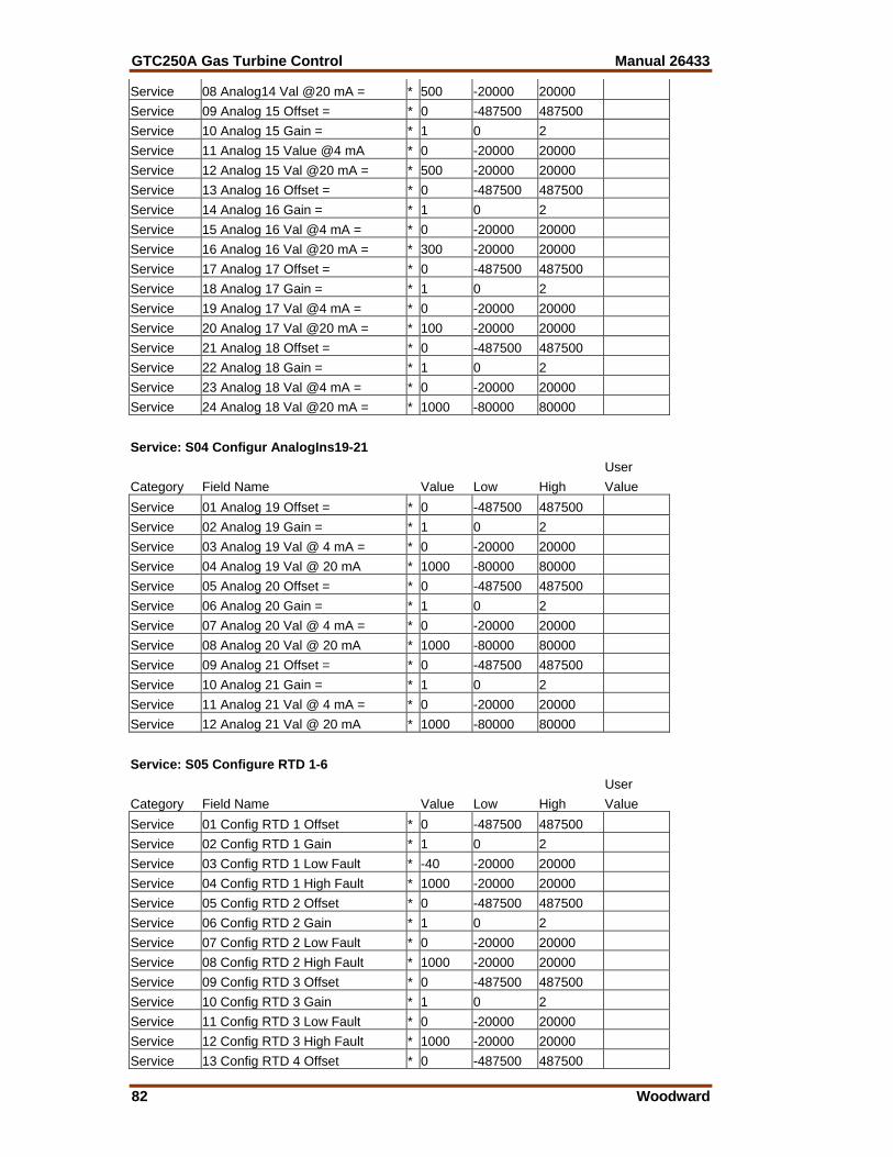
GTC250A Gas Turbine Control Manual 26433
82 Woodward
Service 08 Analog14 Val @20 mA = * 500 -20000 20000 Service 09 Analog 15 Offset = * 0 -487500 487500 Service 10 Analog 15 Gain = * 1 0 2 Service 11 Analog 15 Value @4 mA * 0 -20000 20000 Service 12 Analog 15 Val @20 mA = * 500 -20000 20000 Service 13 Analog 16 Offset = * 0 -487500 487500 Service 14 Analog 16 Gain = * 1 0 2 Service 15 Analog 16 Val @4 mA = * 0 -20000 20000 Service 16 Analog 16 Val @20 mA = * 300 -20000 20000 Service 17 Analog 17 Offset = * 0 -487500 487500 Service 18 Analog 17 Gain = * 1 0 2 Service 19 Analog 17 Val @4 mA = * 0 -20000 20000 Service 20 Analog 17 Val @20 mA = * 100 -20000 20000 Service 21 Analog 18 Offset = * 0 -487500 487500 Service 22 Analog 18 Gain = * 1 0 2 Service 23 Analog 18 Val @4 mA = * 0 -20000 20000 Service 24 Analog 18 Val @20 mA = * 1000 -80000 80000 Service: S04 Configur AnalogIns19-21 User Category Field Name Value Low High Value Service 01 Analog 19 Offset = * 0 -487500 487500 Service 02 Analog 19 Gain = * 1 0 2 Service 03 Analog 19 Val @ 4 mA = * 0 -20000 20000 Service 04 Analog 19 Val @ 20 mA * 1000 -80000 80000 Service 05 Analog 20 Offset = * 0 -487500 487500 Service 06 Analog 20 Gain = * 1 0 2 Service 07 Analog 20 Val @ 4 mA = * 0 -20000 20000 Service 08 Analog 20 Val @ 20 mA * 1000 -80000 80000 Service 09 Analog 21 Offset = * 0 -487500 487500 Service 10 Analog 21 Gain = * 1 0 2 Service 11 Analog 21 Val @ 4 mA = * 0 -20000 20000 Service 12 Analog 21 Val @ 20 mA * 1000 -80000 80000 Service: S05 Configure RTD 1-6 User Category Field Name Value Low High Value Service 01 Config RTD 1 Offset * 0 -487500 487500 Service 02 Config RTD 1 Gain * 1 0 2 Service 03 Config RTD 1 Low Fault * -40 -20000 20000 Service 04 Config RTD 1 High Fault * 1000 -20000 20000 Service 05 Config RTD 2 Offset * 0 -487500 487500 Service 06 Config RTD 2 Gain * 1 0 2 Service 07 Config RTD 2 Low Fault * 0 -20000 20000 Service 08 Config RTD 2 High Fault * 1000 -20000 20000 Service 09 Config RTD 3 Offset * 0 -487500 487500 Service 10 Config RTD 3 Gain * 1 0 2 Service 11 Config RTD 3 Low Fault * 0 -20000 20000 Service 12 Config RTD 3 High Fault * 1000 -20000 20000 Service 13 Config RTD 4 Offset * 0 -487500 487500
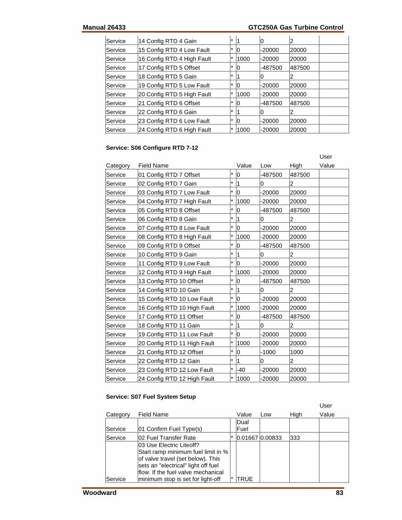
Manual 26433 GTC250A Gas Turbine Control
Woodward 83
Service 14 Config RTD 4 Gain * 1 0 2 Service 15 Config RTD 4 Low Fault * 0 -20000 20000 Service 16 Config RTD 4 High Fault * 1000 -20000 20000 Service 17 Config RTD 5 Offset * 0 -487500 487500 Service 18 Config RTD 5 Gain * 1 0 2 Service 19 Config RTD 5 Low Fault * 0 -20000 20000 Service 20 Config RTD 5 High Fault * 1000 -20000 20000 Service 21 Config RTD 6 Offset * 0 -487500 487500 Service 22 Config RTD 6 Gain * 1 0 2 Service 23 Config RTD 6 Low Fault * 0 -20000 20000 Service 24 Config RTD 6 High Fault * 1000 -20000 20000 Service: S06 Configure RTD 7-12 User Category Field Name Value Low High Value Service 01 Config RTD 7 Offset * 0 -487500 487500 Service 02 Config RTD 7 Gain * 1 0 2 Service 03 Config RTD 7 Low Fault * 0 -20000 20000 Service 04 Config RTD 7 High Fault * 1000 -20000 20000 Service 05 Config RTD 8 Offset * 0 -487500 487500 Service 06 Config RTD 8 Gain * 1 0 2 Service 07 Config RTD 8 Low Fault * 0 -20000 20000 Service 08 Config RTD 8 High Fault * 1000 -20000 20000 Service 09 Config RTD 9 Offset * 0 -487500 487500 Service 10 Config RTD 9 Gain * 1 0 2 Service 11 Config RTD 9 Low Fault * 0 -20000 20000 Service 12 Config RTD 9 High Fault * 1000 -20000 20000 Service 13 Config RTD 10 Offset * 0 -487500 487500 Service 14 Config RTD 10 Gain * 1 0 2 Service 15 Config RTD 10 Low Fault * 0 -20000 20000 Service 16 Config RTD 10 High Fault * 1000 -20000 20000 Service 17 Config RTD 11 Offset * 0 -487500 487500 Service 18 Config RTD 11 Gain * 1 0 2 Service 19 Config RTD 11 Low Fault * 0 -20000 20000 Service 20 Config RTD 11 High Fault * 1000 -20000 20000 Service 21 Config RTD 12 Offset * 0 -1000 1000 Service 22 Config RTD 12 Gain * 1 0 2 Service 23 Config RTD 12 Low Fault * -40 -20000 20000 Service 24 Config RTD 12 High Fault * 1000 -20000 20000 Service: S07 Fuel System Setup User Category Field Name Value Low High Value
Service 01 Confirm Fuel Type(s) Dual Fuel
Service 02 Fuel Transfer Rate * 0.01667 0.00833 333
Service
03 Use Electric Liteoff? Start ramp minimum fuel limit in % of valve travel (set below). This sets an "electrical" light off fuel flow. If the fuel valve mechanical minimum stop is set for light-off * TRUE
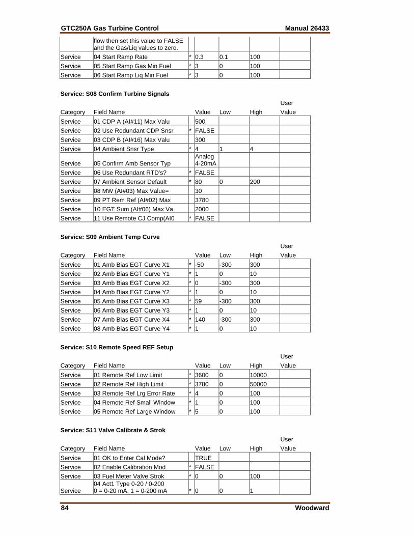
GTC250A Gas Turbine Control Manual 26433
84 Woodward
flow then set this value to FALSE and the Gas/Liq values to zero.
Service 04 Start Ramp Rate * 0.3 0.1 100 Service 05 Start Ramp Gas Min Fuel * 3 0 100 Service 06 Start Ramp Liq Min Fuel * 3 0 100 Service: S08 Confirm Turbine Signals User Category Field Name Value Low High Value Service 01 CDP A (AI#11) Max Valu 500 Service 02 Use Redundant CDP Snsr * FALSE Service 03 CDP B (AI#16) Max Valu 300 Service 04 Ambient Snsr Type * 4 1 4
Service 05 Confirm Amb Sensor Typ Analog 4-20mA
Service 06 Use Redundant RTD's? * FALSE Service 07 Ambient Sensor Default * 80 0 200 Service 08 MW (AI#03) Max Value= 30 Service 09 PT Rem Ref (AI#02) Max 3780 Service 10 EGT Sum (AI#06) Max Va 2000 Service 11 Use Remote CJ Comp(AI0 * FALSE Service: S09 Ambient Temp Curve User Category Field Name Value Low High Value Service 01 Amb Bias EGT Curve X1 * -50 -300 300 Service 02 Amb Bias EGT Curve Y1 * 1 0 10 Service 03 Amb Bias EGT Curve X2 * 0 -300 300 Service 04 Amb Bias EGT Curve Y2 * 1 0 10 Service 05 Amb Bias EGT Curve X3 * 59 -300 300 Service 06 Amb Bias EGT Curve Y3 * 1 0 10 Service 07 Amb Bias EGT Curve X4 * 140 -300 300 Service 08 Amb Bias EGT Curve Y4 * 1 0 10 Service: S10 Remote Speed REF Setup User Category Field Name Value Low High Value Service 01 Remote Ref Low Limit * 3600 0 10000 Service 02 Remote Ref High Limit * 3780 0 50000 Service 03 Remote Ref Lrg Error Rate * 4 0 100 Service 04 Remote Ref Small Window * 1 0 100 Service 05 Remote Ref Large Window * 5 0 100 Service: S11 Valve Calibrate & Strok User Category Field Name Value Low High Value Service 01 OK to Enter Cal Mode? TRUE Service 02 Enable Calibration Mod * FALSE Service 03 Fuel Meter Valve Strok * 0 0 100
Service 04 Act1 Type 0-20 / 0-200 0 = 0-20 mA, 1 = 0-200 mA * 0 0 1
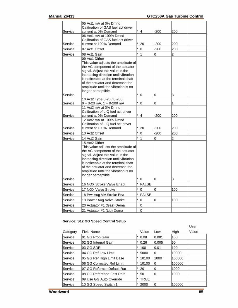
Manual 26433 GTC250A Gas Turbine Control
Woodward 85
Service
05 Act1 mA at 0% Dmnd Calibration of GAS fuel act driver current at 0% Demand * 4 -200 200
Service
06 Act1 mA at 100% Dmnd Calibration of GAS fuel act driver current at 100% Demand * 20 -200 200
Service 07 Act1 Offset * 0 -200 200 Service 08 Act1 Gain * 1 0 2
Service
09 Act1 Dither This value adjusts the amplitude of the AC component of the actuator signal. Adjust this value in the increasing direction until vibration is noticeable at the terminal shaft of the actuator and decrease the amplitude until the vibration is no longer perceptible. * 0 0 3
Service 10 Act2 Type 0-20 / 0-200 0 = 0-20 mA, 1 = 0-200 mA * 0 0 1
Service
11 Act2 mA at 0% Dmnd Calibration of LIQ fuel act driver current at 0% Demand * 4 -200 200
Service
12 Act2 mA at 100% Dmnd Calibration of LIQ fuel act driver current at 100% Demand * 20 -200 200
Service 13 Act2 Offset * 0 -200 200 Service 14 Act2 Gain * 1 0 2
Service
15 Act2 Dither This value adjusts the amplitude of the AC component of the actuator signal. Adjust this value in the increasing direction until vibration is noticeable at the terminal shaft of the actuator and decrease the amplitude until the vibration is no longer perceptible. * 0 0 3
Service 16 NOX Stroke Valve Enabl * FALSE Service 17 NOX Valve Stroke * 0 0 100 Service 18 Pwr Aug Vlv Stroke Ena * FALSE Service 19 Power Aug Valve Stroke * 0 0 100 Service 20 Actuator #1 (Gas) Dema 0 Service 21 Actuator #1 (Liq) Dema 0 Service: S12 GG Speed Control Setup User Category Field Name Value Low High Value Service 01 GG Prop Gain * 0.08 0.001 100 Service 02 GG Integral Gain * 0.26 0.005 50 Service 03 GG SDR * 100 0.01 100 Service 04 GG Ref Low Limit * 5000 0 10000 Service 05 GG Ref High Limit Base * 10100 1000 100000 Service 06 GG Corrected Ref Limit * 10100 0 100000 Service 07 GG Refernce Default Rat * 20 0 1000 Service 08 GG Reference Fast Rate * 50 0 1000 Service 09 Use GG Auto Override * TRUE Service 10 GG Speed Switch 1 * 2000 0 100000
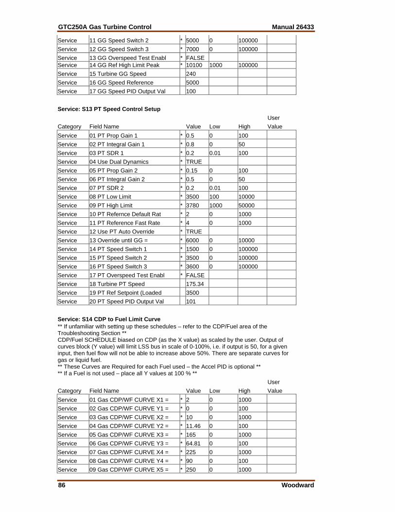
GTC250A Gas Turbine Control Manual 26433
86 Woodward
Service 11 GG Speed Switch 2 * 5000 0 100000 Service 12 GG Speed Switch 3 * 7000 0 100000 Service 13 GG Overspeed Test Enabl * FALSE Service 14 GG Ref High Limit Peak * 10100 1000 100000 Service 15 Turbine GG Speed 240 Service 16 GG Speed Reference 5000 Service 17 GG Speed PID Output Val 100 Service: S13 PT Speed Control Setup User Category Field Name Value Low High Value Service 01 PT Prop Gain 1 * 0.5 0 100 Service 02 PT Integral Gain 1 * 0.8 0 50 Service 03 PT SDR 1 * 0.2 0.01 100 Service 04 Use Dual Dynamics * TRUE Service 05 PT Prop Gain 2 * 0.15 0 100 Service 06 PT Integral Gain 2 * 0.5 0 50 Service 07 PT SDR 2 * 0.2 0.01 100 Service 08 PT Low Limit * 3500 100 10000 Service 09 PT High Limit * 3780 1000 50000 Service 10 PT Refernce Default Rat * 2 0 1000 Service 11 PT Reference Fast Rate * 4 0 1000 Service 12 Use PT Auto Override * TRUE Service 13 Override until GG = * 6000 0 10000 Service 14 PT Speed Switch 1 * 1500 0 100000 Service 15 PT Speed Switch 2 * 3500 0 100000 Service 16 PT Speed Switch 3 * 3600 0 100000 Service 17 PT Overspeed Test Enabl * FALSE Service 18 Turbine PT Speed 175.34 Service 19 PT Ref Setpoint (Loaded 3500 Service 20 PT Speed PID Output Val 101 Service: S14 CDP to Fuel Limit Curve ** If unfamiliar with setting up these schedules – refer to the CDP/Fuel area of the Troubleshooting Section ** CDP/Fuel SCHEDULE biased on CDP (as the X value) as scaled by the user. Output of curves block (Y value) will limit LSS bus in scale of 0-100%, i.e. if output is 50, for a given input, then fuel flow will not be able to increase above 50%. There are separate curves for gas or liquid fuel. ** These Curves are Required for each Fuel used – the Accel PID is optional ** ** If a Fuel is not used – place all Y values at 100 % ** User Category Field Name Value Low High Value Service 01 Gas CDP/WF CURVE X1 = * 2 0 1000 Service 02 Gas CDP/WF CURVE Y1 = * 0 0 100 Service 03 Gas CDP/WF CURVE X2 = * 10 0 1000 Service 04 Gas CDP/WF CURVE Y2 = * 11.46 0 100 Service 05 Gas CDP/WF CURVE X3 = * 165 0 1000 Service 06 Gas CDP/WF CURVE Y3 = * 64.81 0 100 Service 07 Gas CDP/WF CURVE X4 = * 225 0 1000 Service 08 Gas CDP/WF CURVE Y4 = * 90 0 100 Service 09 Gas CDP/WF CURVE X5 = * 250 0 1000
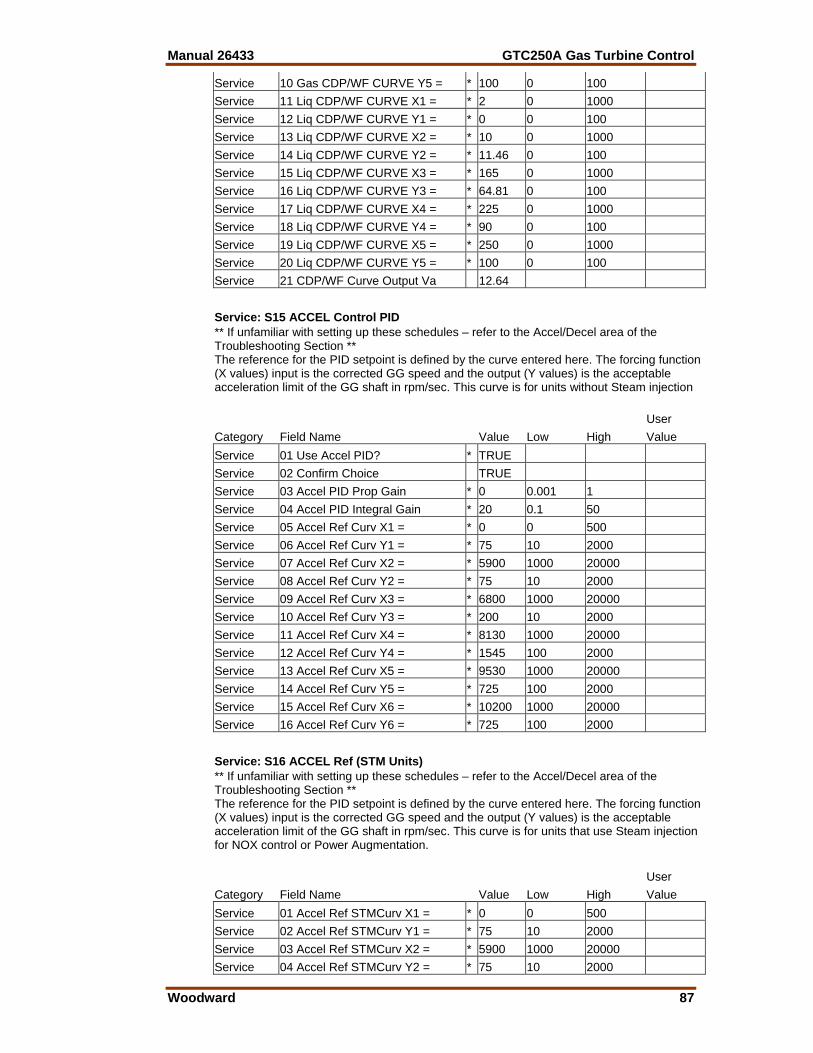
Manual 26433 GTC250A Gas Turbine Control
Woodward 87
Service 10 Gas CDP/WF CURVE Y5 = * 100 0 100 Service 11 Liq CDP/WF CURVE X1 = * 2 0 1000 Service 12 Liq CDP/WF CURVE Y1 = * 0 0 100 Service 13 Liq CDP/WF CURVE X2 = * 10 0 1000 Service 14 Liq CDP/WF CURVE Y2 = * 11.46 0 100 Service 15 Liq CDP/WF CURVE X3 = * 165 0 1000 Service 16 Liq CDP/WF CURVE Y3 = * 64.81 0 100 Service 17 Liq CDP/WF CURVE X4 = * 225 0 1000 Service 18 Liq CDP/WF CURVE Y4 = * 90 0 100 Service 19 Liq CDP/WF CURVE X5 = * 250 0 1000 Service 20 Liq CDP/WF CURVE Y5 = * 100 0 100 Service 21 CDP/WF Curve Output Va 12.64 Service: S15 ACCEL Control PID ** If unfamiliar with setting up these schedules – refer to the Accel/Decel area of the Troubleshooting Section ** The reference for the PID setpoint is defined by the curve entered here. The forcing function (X values) input is the corrected GG speed and the output (Y values) is the acceptable acceleration limit of the GG shaft in rpm/sec. This curve is for units without Steam injection User Category Field Name Value Low High Value Service 01 Use Accel PID? * TRUE Service 02 Confirm Choice TRUE Service 03 Accel PID Prop Gain * 0 0.001 1 Service 04 Accel PID Integral Gain * 20 0.1 50 Service 05 Accel Ref Curv X1 = * 0 0 500 Service 06 Accel Ref Curv Y1 = * 75 10 2000 Service 07 Accel Ref Curv X2 = * 5900 1000 20000 Service 08 Accel Ref Curv Y2 = * 75 10 2000 Service 09 Accel Ref Curv X3 = * 6800 1000 20000 Service 10 Accel Ref Curv Y3 = * 200 10 2000 Service 11 Accel Ref Curv X4 = * 8130 1000 20000 Service 12 Accel Ref Curv Y4 = * 1545 100 2000 Service 13 Accel Ref Curv X5 = * 9530 1000 20000 Service 14 Accel Ref Curv Y5 = * 725 100 2000 Service 15 Accel Ref Curv X6 = * 10200 1000 20000 Service 16 Accel Ref Curv Y6 = * 725 100 2000 Service: S16 ACCEL Ref (STM Units) ** If unfamiliar with setting up these schedules – refer to the Accel/Decel area of the Troubleshooting Section ** The reference for the PID setpoint is defined by the curve entered here. The forcing function (X values) input is the corrected GG speed and the output (Y values) is the acceptable acceleration limit of the GG shaft in rpm/sec. This curve is for units that use Steam injection for NOX control or Power Augmentation. User Category Field Name Value Low High Value Service 01 Accel Ref STMCurv X1 = * 0 0 500 Service 02 Accel Ref STMCurv Y1 = * 75 10 2000 Service 03 Accel Ref STMCurv X2 = * 5900 1000 20000 Service 04 Accel Ref STMCurv Y2 = * 75 10 2000
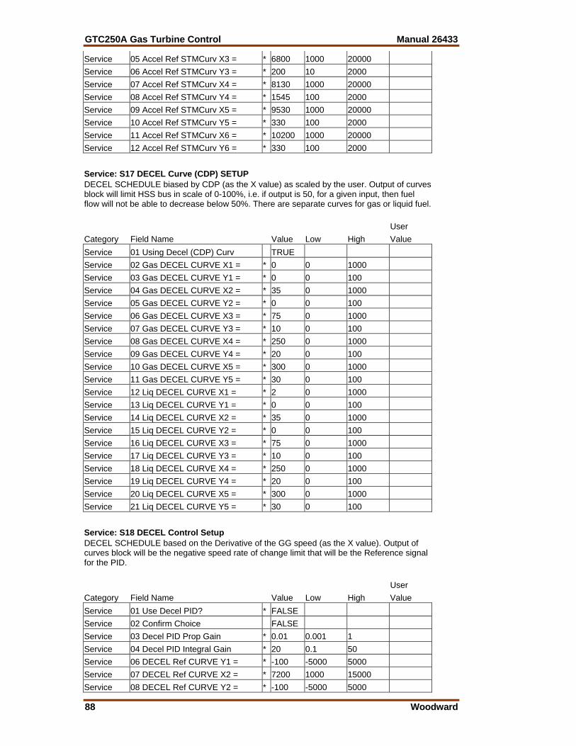
GTC250A Gas Turbine Control Manual 26433
88 Woodward
Service 05 Accel Ref STMCurv X3 = * 6800 1000 20000 Service 06 Accel Ref STMCurv Y3 = * 200 10 2000 Service 07 Accel Ref STMCurv X4 = * 8130 1000 20000 Service 08 Accel Ref STMCurv Y4 = * 1545 100 2000 Service 09 Accel Ref STMCurv X5 = * 9530 1000 20000 Service 10 Accel Ref STMCurv Y5 = * 330 100 2000 Service 11 Accel Ref STMCurv X6 = * 10200 1000 20000 Service 12 Accel Ref STMCurv Y6 = * 330 100 2000 Service: S17 DECEL Curve (CDP) SETUP DECEL SCHEDULE biased by CDP (as the X value) as scaled by the user. Output of curves block will limit HSS bus in scale of 0-100%, i.e. if output is 50, for a given input, then fuel flow will not be able to decrease below 50%. There are separate curves for gas or liquid fuel. User Category Field Name Value Low High Value Service 01 Using Decel (CDP) Curv TRUE Service 02 Gas DECEL CURVE X1 = * 0 0 1000 Service 03 Gas DECEL CURVE Y1 = * 0 0 100 Service 04 Gas DECEL CURVE X2 = * 35 0 1000 Service 05 Gas DECEL CURVE Y2 = * 0 0 100 Service 06 Gas DECEL CURVE X3 = * 75 0 1000 Service 07 Gas DECEL CURVE Y3 = * 10 0 100 Service 08 Gas DECEL CURVE X4 = * 250 0 1000 Service 09 Gas DECEL CURVE Y4 = * 20 0 100 Service 10 Gas DECEL CURVE X5 = * 300 0 1000 Service 11 Gas DECEL CURVE Y5 = * 30 0 100 Service 12 Liq DECEL CURVE X1 = * 2 0 1000 Service 13 Liq DECEL CURVE Y1 = * 0 0 100 Service 14 Liq DECEL CURVE X2 = * 35 0 1000 Service 15 Liq DECEL CURVE Y2 = * 0 0 100 Service 16 Liq DECEL CURVE X3 = * 75 0 1000 Service 17 Liq DECEL CURVE Y3 = * 10 0 100 Service 18 Liq DECEL CURVE X4 = * 250 0 1000 Service 19 Liq DECEL CURVE Y4 = * 20 0 100 Service 20 Liq DECEL CURVE X5 = * 300 0 1000 Service 21 Liq DECEL CURVE Y5 = * 30 0 100 Service: S18 DECEL Control Setup DECEL SCHEDULE based on the Derivative of the GG speed (as the X value). Output of curves block will be the negative speed rate of change limit that will be the Reference signal for the PID. User Category Field Name Value Low High Value Service 01 Use Decel PID? * FALSE Service 02 Confirm Choice FALSE Service 03 Decel PID Prop Gain * 0.01 0.001 1 Service 04 Decel PID Integral Gain * 20 0.1 50 Service 06 DECEL Ref CURVE Y1 = * -100 -5000 5000 Service 07 DECEL Ref CURVE X2 = * 7200 1000 15000 Service 08 DECEL Ref CURVE Y2 = * -100 -5000 5000
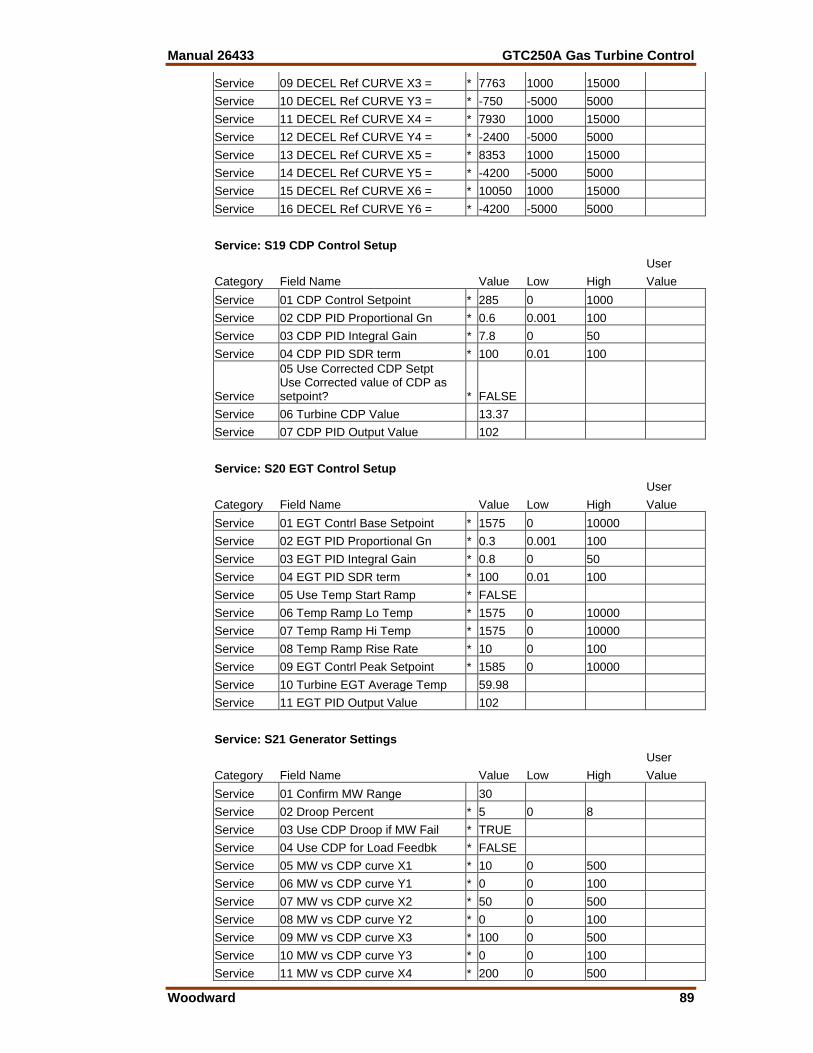
Manual 26433 GTC250A Gas Turbine Control
Woodward 89
Service 09 DECEL Ref CURVE X3 = * 7763 1000 15000 Service 10 DECEL Ref CURVE Y3 = * -750 -5000 5000 Service 11 DECEL Ref CURVE X4 = * 7930 1000 15000 Service 12 DECEL Ref CURVE Y4 = * -2400 -5000 5000 Service 13 DECEL Ref CURVE X5 = * 8353 1000 15000 Service 14 DECEL Ref CURVE Y5 = * -4200 -5000 5000 Service 15 DECEL Ref CURVE X6 = * 10050 1000 15000 Service 16 DECEL Ref CURVE Y6 = * -4200 -5000 5000 Service: S19 CDP Control Setup User Category Field Name Value Low High Value Service 01 CDP Control Setpoint * 285 0 1000 Service 02 CDP PID Proportional Gn * 0.6 0.001 100 Service 03 CDP PID Integral Gain * 7.8 0 50 Service 04 CDP PID SDR term * 100 0.01 100
Service
05 Use Corrected CDP Setpt Use Corrected value of CDP as setpoint? * FALSE
Service 06 Turbine CDP Value 13.37 Service 07 CDP PID Output Value 102 Service: S20 EGT Control Setup User Category Field Name Value Low High Value Service 01 EGT Contrl Base Setpoint * 1575 0 10000 Service 02 EGT PID Proportional Gn * 0.3 0.001 100 Service 03 EGT PID Integral Gain * 0.8 0 50 Service 04 EGT PID SDR term * 100 0.01 100 Service 05 Use Temp Start Ramp * FALSE Service 06 Temp Ramp Lo Temp * 1575 0 10000 Service 07 Temp Ramp Hi Temp * 1575 0 10000 Service 08 Temp Ramp Rise Rate * 10 0 100 Service 09 EGT Contrl Peak Setpoint * 1585 0 10000 Service 10 Turbine EGT Average Temp 59.98 Service 11 EGT PID Output Value 102 Service: S21 Generator Settings User Category Field Name Value Low High Value Service 01 Confirm MW Range 30 Service 02 Droop Percent * 5 0 8 Service 03 Use CDP Droop if MW Fail * TRUE Service 04 Use CDP for Load Feedbk * FALSE Service 05 MW vs CDP curve X1 * 10 0 500 Service 06 MW vs CDP curve Y1 * 0 0 100 Service 07 MW vs CDP curve X2 * 50 0 500 Service 08 MW vs CDP curve Y2 * 0 0 100 Service 09 MW vs CDP curve X3 * 100 0 500 Service 10 MW vs CDP curve Y3 * 0 0 100 Service 11 MW vs CDP curve X4 * 200 0 500
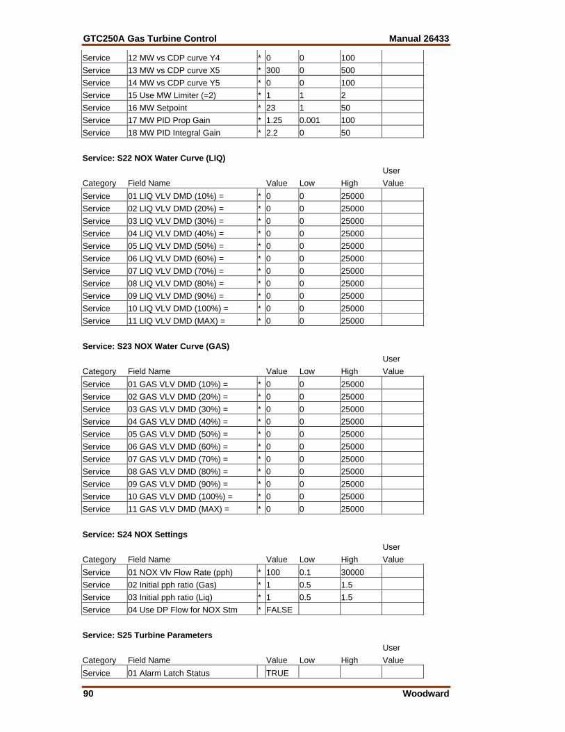
GTC250A Gas Turbine Control Manual 26433
90 Woodward
Service 12 MW vs CDP curve Y4 * 0 0 100 Service 13 MW vs CDP curve X5 * 300 0 500 Service 14 MW vs CDP curve Y5 * 0 0 100 Service 15 Use MW Limiter (=2) * 1 1 2 Service 16 MW Setpoint * 23 1 50 Service 17 MW PID Prop Gain * 1.25 0.001 100 Service 18 MW PID Integral Gain * 2.2 0 50 Service: S22 NOX Water Curve (LIQ) User Category Field Name Value Low High Value Service 01 LIQ VLV DMD (10%) = * 0 0 25000 Service 02 LIQ VLV DMD (20%) = * 0 0 25000 Service 03 LIQ VLV DMD (30%) = * 0 0 25000 Service 04 LIQ VLV DMD (40%) = * 0 0 25000 Service 05 LIQ VLV DMD (50%) = * 0 0 25000 Service 06 LIQ VLV DMD (60%) = * 0 0 25000 Service 07 LIQ VLV DMD (70%) = * 0 0 25000 Service 08 LIQ VLV DMD (80%) = * 0 0 25000 Service 09 LIQ VLV DMD (90%) = * 0 0 25000 Service 10 LIQ VLV DMD (100%) = * 0 0 25000 Service 11 LIQ VLV DMD (MAX) = * 0 0 25000 Service: S23 NOX Water Curve (GAS) User Category Field Name Value Low High Value Service 01 GAS VLV DMD (10%) = * 0 0 25000 Service 02 GAS VLV DMD (20%) = * 0 0 25000 Service 03 GAS VLV DMD (30%) = * 0 0 25000 Service 04 GAS VLV DMD (40%) = * 0 0 25000 Service 05 GAS VLV DMD (50%) = * 0 0 25000 Service 06 GAS VLV DMD (60%) = * 0 0 25000 Service 07 GAS VLV DMD (70%) = * 0 0 25000 Service 08 GAS VLV DMD (80%) = * 0 0 25000 Service 09 GAS VLV DMD (90%) = * 0 0 25000 Service 10 GAS VLV DMD (100%) = * 0 0 25000 Service 11 GAS VLV DMD (MAX) = * 0 0 25000 Service: S24 NOX Settings User Category Field Name Value Low High Value Service 01 NOX Vlv Flow Rate (pph) * 100 0.1 30000 Service 02 Initial pph ratio (Gas) * 1 0.5 1.5 Service 03 Initial pph ratio (Liq) * 1 0.5 1.5 Service 04 Use DP Flow for NOX Stm * FALSE Service: S25 Turbine Parameters User Category Field Name Value Low High Value Service 01 Alarm Latch Status TRUE
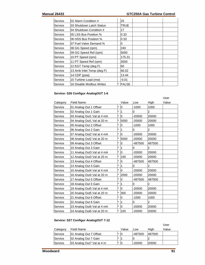
Manual 26433 GTC250A Gas Turbine Control
Woodward 91
Service 02 Alarm Condition # 25 Service 03 Shutdown Latch Status TRUE Service 04 Shutdown Condition # 17 Service 05 LSS Bus Position % 0.33 Service 06 HSS Bus Position % 0.33 Service 07 Fuel Valve Demand % 0 Service 08 GG Speed (rpm) 240 Service 09 GG Speed Ref (rpm) 5000 Service 10 PT Speed (rpm) 175.31 Service 11 PT Speed Ref (rpm) 3500 Service 12 EGT Temp (deg F) 60 Service 13 Amb Inlet Temp (deg F) 66.02 Service 14 CDP (psia) 13.44 Service 15 Turbine Load (mw) -0.01 Service 16 Disable Modbus Writes * FALSE Service: S26 Configur AnalogOUT 1-6 User Category Field Name Value Low High Value Service 01 Analog Out 1 Offset * 0 -1000 1000 Service 02 Analog Out 1 Gain * 1 0 2 Service 03 Analog Out1 Val at 4 mA * 0 -20000 20000 Service 04 Analog Out1 Val at 20 m * 5000 -20000 20000 Service 05 Analog Out 2 Offset * 0 -1000 1000 Service 06 Analog Out 2 Gain * 1 0 2 Service 07 Analog Out2 Val at 4 mA * 0 -20000 20000 Service 08 Analog Out2 Val at 20 m * 5000 -20000 20000 Service 09 Analog Out 3 Offset * 0 -487500 487500 Service 10 Analog Out 3 Gain * 1 0 2 Service 11 Analog Out3 Val at 4 mA * 0 -20000 20000 Service 12 Analog Out3 Val at 20 m * 100 -20000 20000 Service 13 Analog Out 4 Offset * 0 -487500 487500 Service 14 Analog Out 4 Gain * 1 0 2 Service 15 Analog Out4 Val at 4 mA * 0 -20000 20000 Service 16 Analog Out4 Val at 20 m * 2000 -20000 20000 Service 17 Analog Out 5 Offset * 0 -487500 487500 Service 18 Analog Out 5 Gain * 1 0 2 Service 19 Analog Out5 Val at 4 mA * 0 -20000 20000 Service 20 Analog Out5 Val at 20 m * 300 -20000 20000 Service 21 Analog Out 6 Offset * 0 -1000 1000 Service 22 Analog Out 6 Gain * 1 0 2 Service 23 Analog Out6 Val at 4 mA * 0 -20000 20000 Service 24 Analog Out6 Val at 20 m * 100 -20000 20000 Service: S27 Configur AnalogOUT 7-12 User Category Field Name Value Low High Value Service 01 Analog Out 7 Offset * 0 -487500 487500 Service 02 Analog Out 7 Gain * 1 0 2 Service 03 Analog Out7 Val at 4 m * 0 -20000 20000
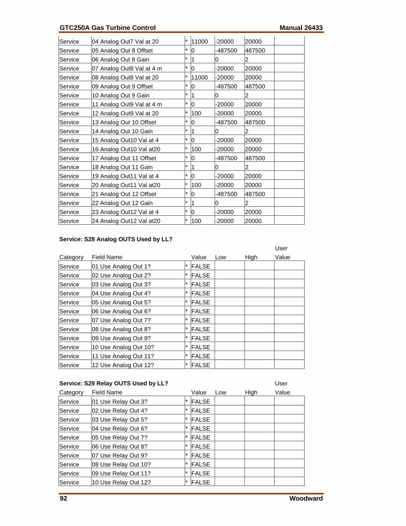
GTC250A Gas Turbine Control Manual 26433
92 Woodward
Service 04 Analog Out7 Val at 20 * 11000 -20000 20000 Service 05 Analog Out 8 Offset * 0 -487500 487500 Service 06 Analog Out 8 Gain * 1 0 2 Service 07 Analog Out8 Val at 4 m * 0 -20000 20000 Service 08 Analog Out8 Val at 20 * 11000 -20000 20000 Service 09 Analog Out 9 Offset * 0 -487500 487500 Service 10 Analog Out 9 Gain * 1 0 2 Service 11 Analog Out9 Val at 4 m * 0 -20000 20000 Service 12 Analog Out9 Val at 20 * 100 -20000 20000 Service 13 Analog Out 10 Offset * 0 -487500 487500 Service 14 Analog Out 10 Gain * 1 0 2 Service 15 Analog Out10 Val at 4 * 0 -20000 20000 Service 16 Analog Out10 Val at20 * 100 -20000 20000 Service 17 Analog Out 11 Offset * 0 -487500 487500 Service 18 Analog Out 11 Gain * 1 0 2 Service 19 Analog Out11 Val at 4 * 0 -20000 20000 Service 20 Analog Out11 Val at20 * 100 -20000 20000 Service 21 Analog Out 12 Offset * 0 -487500 487500 Service 22 Analog Out 12 Gain * 1 0 2 Service 23 Analog Out12 Val at 4 * 0 -20000 20000 Service 24 Analog Out12 Val at20 * 100 -20000 20000 Service: S28 Analog OUTS Used by LL? User Category Field Name Value Low High Value Service 01 Use Analog Out 1? * FALSE Service 02 Use Analog Out 2? * FALSE Service 03 Use Analog Out 3? * FALSE Service 04 Use Analog Out 4? * FALSE Service 05 Use Analog Out 5? * FALSE Service 06 Use Analog Out 6? * FALSE Service 07 Use Analog Out 7? * FALSE Service 08 Use Analog Out 8? * FALSE Service 09 Use Analog Out 9? * FALSE Service 10 Use Analog Out 10? * FALSE Service 11 Use Analog Out 11? * FALSE Service 12 Use Analog Out 12? * FALSE Service: S29 Relay OUTS Used by LL? User Category Field Name Value Low High Value Service 01 Use Relay Out 3? * FALSE Service 02 Use Relay Out 4? * FALSE Service 03 Use Relay Out 5? * FALSE Service 04 Use Relay Out 6? * FALSE Service 05 Use Relay Out 7? * FALSE Service 06 Use Relay Out 8? * FALSE Service 07 Use Relay Out 9? * FALSE Service 08 Use Relay Out 10? * FALSE Service 09 Use Relay Out 11? * FALSE Service 10 Use Relay Out 12? * FALSE
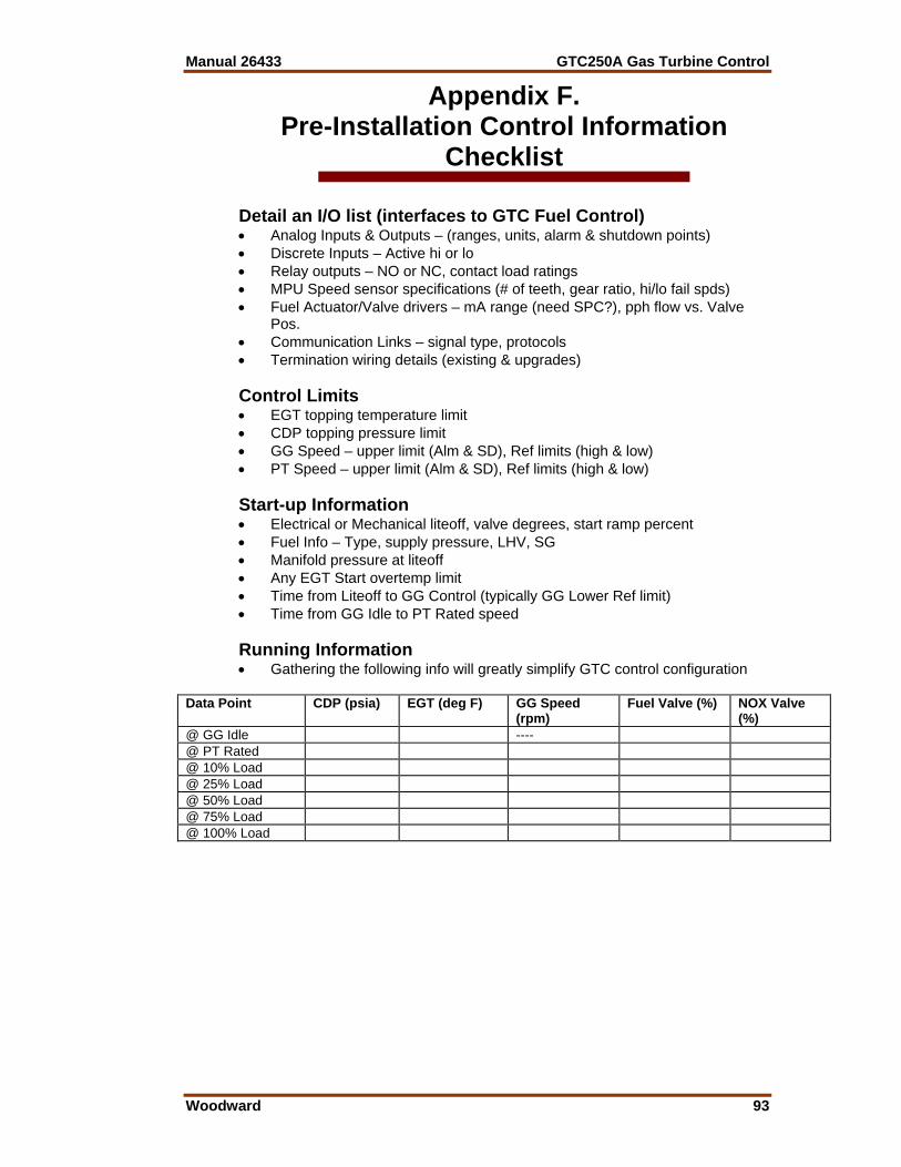
Manual 26433 GTC250A Gas Turbine Control
Woodward 93
Appendix F. Pre-Installation Control Information
Checklist Detail an I/O list (interfaces to GTC Fuel Control) • Analog Inputs & Outputs – (ranges, units, alarm & shutdown points) • Discrete Inputs – Active hi or lo • Relay outputs – NO or NC, contact load ratings • MPU Speed sensor specifications (# of teeth, gear ratio, hi/lo fail spds) • Fuel Actuator/Valve drivers – mA range (need SPC?), pph flow vs. Valve
Pos. • Communication Links – signal type, protocols • Termination wiring details (existing & upgrades) Control Limits • EGT topping temperature limit • CDP topping pressure limit • GG Speed – upper limit (Alm & SD), Ref limits (high & low) • PT Speed – upper limit (Alm & SD), Ref limits (high & low) Start-up Information • Electrical or Mechanical liteoff, valve degrees, start ramp percent • Fuel Info – Type, supply pressure, LHV, SG • Manifold pressure at liteoff • Any EGT Start overtemp limit • Time from Liteoff to GG Control (typically GG Lower Ref limit) • Time from GG Idle to PT Rated speed Running Information • Gathering the following info will greatly simplify GTC control configuration
Data Point CDP (psia) EGT (deg F) GG Speed (rpm)
Fuel Valve (%) NOX Valve (%)
@ GG Idle ---- @ PT Rated @ 10% Load @ 25% Load @ 50% Load @ 75% Load @ 100% Load

GTC250A Gas Turbine Control Manual 26433
94 Woodward
Appendix G. Interfacing to Distributed IO & Ladder
Logic (8262-1031 Unit)
Adding Ladder Logic Programming into the GTC250A The system documentation CD contains the source code of the Master GAP file (or sometimes called the Second-ring file). Customers intending to incorporate additional programming into the Atlas control will need to utilize this file. The programmer should have a good working knowledge of GAP programming and the use of the GAP editor tool, including a clear understanding of what the meaning of terms template and coder versions. In most cases the GTC250A GAP file will be used as a reference in finding the software ‘handles’ (both input & output) of the control signals and also the tunable fields that have been programmed as being available to the Ladder Logic programming environment. Input fields that are available for LL control are identified with a boxed LL designation. The programmer can pass any GAP block output field to Ladder Logic for use in programming. The GTC250A does not include the application tool required to write the program that is intended to reside on the GTC250A. Additional programming help can be found in the GAP help file that will assist the programmer in interfacing the 2 programs together.
Distributed IO Pre-programmed into the GTC250A For the 8262-1031 Control This version of the GTC250A includes a Profibus Distributed IO module in the Atlas-II hardware. This device interfaces with Allen-Bradley Flex IO (1794- series) that should be connected as shown in the control wiring diagram found in Appendix A. This full compliment of DIO was pre-programmed to be “ready-to-use” via the Ladder Logic programming tool and is segregated into a separate GAP file that gets compiled into the executable code through GAP’s multi-GAP interfacing feature. The CD also contains an auxiliary file (applicom.ply) that must be loaded onto the control (via AppManager) that allows the Applicom Profibus module to link the IO into the GAP software. It is possible to use a subset of the modules that are pre-programmed, but adding IO modules will require modifying the GAP and then creating a new Applicom interface file to load on the control.
This process requires additional programming and testing by the user, and careful consideration should be made before undertaking this effort. Many hours of engineering effort can be spent programming and debugging the interfacing of the GAP to a specific type of distributed IO—review the Atlas-II hardware manual for examples of how this is done.
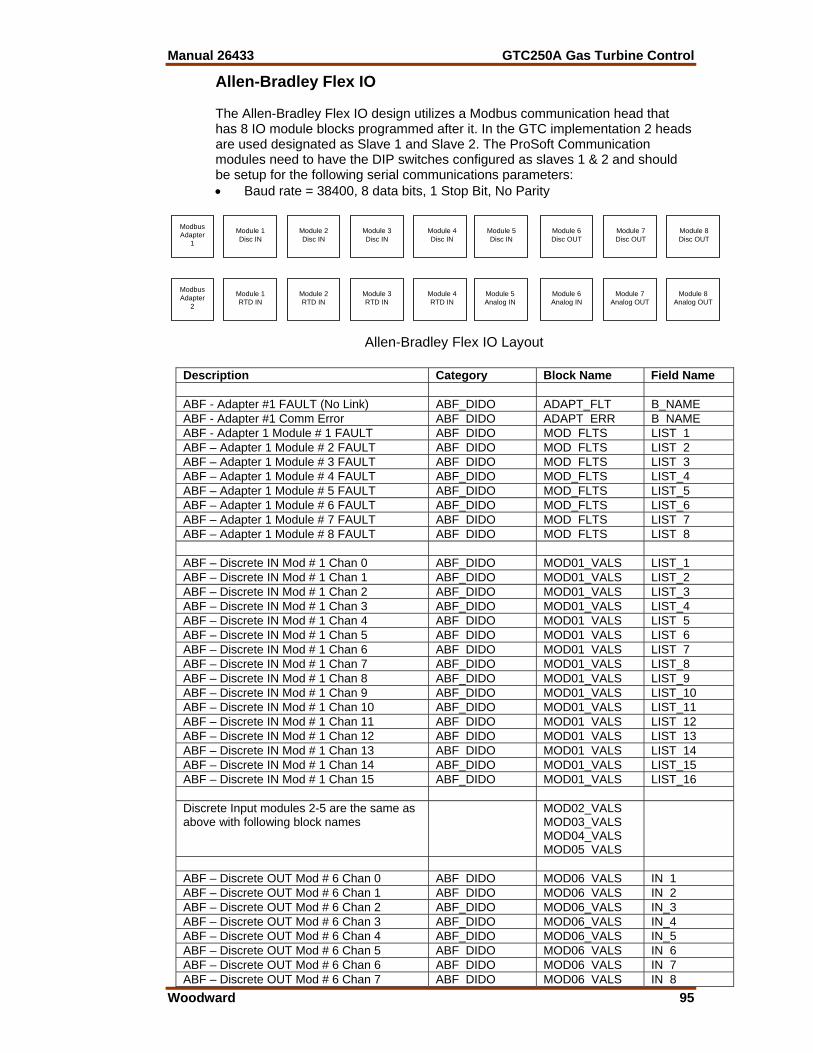
Manual 26433 GTC250A Gas Turbine Control
Woodward 95
Allen-Bradley Flex IO The Allen-Bradley Flex IO design utilizes a Modbus communication head that has 8 IO module blocks programmed after it. In the GTC implementation 2 heads are used designated as Slave 1 and Slave 2. The ProSoft Communication modules need to have the DIP switches configured as slaves 1 & 2 and should be setup for the following serial communications parameters: • Baud rate = 38400, 8 data bits, 1 Stop Bit, No Parity
Description Category Block Name Field Name ABF - Adapter #1 FAULT (No Link) ABF_DIDO ADAPT_FLT B_NAME ABF - Adapter #1 Comm Error ABF DIDO ADAPT ERR B NAME ABF - Adapter 1 Module # 1 FAULT ABF DIDO MOD FLTS LIST 1 ABF – Adapter 1 Module # 2 FAULT ABF DIDO MOD FLTS LIST 2 ABF – Adapter 1 Module # 3 FAULT ABF DIDO MOD FLTS LIST 3 ABF – Adapter 1 Module # 4 FAULT ABF_DIDO MOD_FLTS LIST_4 ABF – Adapter 1 Module # 5 FAULT ABF_DIDO MOD_FLTS LIST_5 ABF – Adapter 1 Module # 6 FAULT ABF_DIDO MOD_FLTS LIST_6 ABF – Adapter 1 Module # 7 FAULT ABF DIDO MOD FLTS LIST 7 ABF – Adapter 1 Module # 8 FAULT ABF DIDO MOD FLTS LIST 8 ABF – Discrete IN Mod # 1 Chan 0 ABF_DIDO MOD01_VALS LIST_1 ABF – Discrete IN Mod # 1 Chan 1 ABF_DIDO MOD01_VALS LIST_2 ABF – Discrete IN Mod # 1 Chan 2 ABF_DIDO MOD01_VALS LIST_3 ABF – Discrete IN Mod # 1 Chan 3 ABF_DIDO MOD01_VALS LIST_4 ABF – Discrete IN Mod # 1 Chan 4 ABF DIDO MOD01 VALS LIST 5 ABF – Discrete IN Mod # 1 Chan 5 ABF DIDO MOD01 VALS LIST 6 ABF – Discrete IN Mod # 1 Chan 6 ABF DIDO MOD01 VALS LIST 7 ABF – Discrete IN Mod # 1 Chan 7 ABF_DIDO MOD01_VALS LIST_8 ABF – Discrete IN Mod # 1 Chan 8 ABF_DIDO MOD01_VALS LIST_9 ABF – Discrete IN Mod # 1 Chan 9 ABF_DIDO MOD01_VALS LIST_10 ABF – Discrete IN Mod # 1 Chan 10 ABF_DIDO MOD01_VALS LIST_11 ABF – Discrete IN Mod # 1 Chan 11 ABF DIDO MOD01 VALS LIST 12 ABF – Discrete IN Mod # 1 Chan 12 ABF DIDO MOD01 VALS LIST 13 ABF – Discrete IN Mod # 1 Chan 13 ABF DIDO MOD01 VALS LIST 14 ABF – Discrete IN Mod # 1 Chan 14 ABF_DIDO MOD01_VALS LIST_15 ABF – Discrete IN Mod # 1 Chan 15 ABF_DIDO MOD01_VALS LIST_16 Discrete Input modules 2-5 are the same as above with following block names
MOD02_VALS MOD03_VALS MOD04_VALS MOD05 VALS
ABF – Discrete OUT Mod # 6 Chan 0 ABF DIDO MOD06 VALS IN 1 ABF – Discrete OUT Mod # 6 Chan 1 ABF DIDO MOD06 VALS IN 2 ABF – Discrete OUT Mod # 6 Chan 2 ABF_DIDO MOD06_VALS IN_3 ABF – Discrete OUT Mod # 6 Chan 3 ABF_DIDO MOD06_VALS IN_4 ABF – Discrete OUT Mod # 6 Chan 4 ABF_DIDO MOD06_VALS IN_5 ABF – Discrete OUT Mod # 6 Chan 5 ABF DIDO MOD06 VALS IN 6 ABF – Discrete OUT Mod # 6 Chan 6 ABF DIDO MOD06 VALS IN 7 ABF – Discrete OUT Mod # 6 Chan 7 ABF DIDO MOD06 VALS IN 8
ModbusAdapter
1
Module 1Disc IN
Module 2Disc IN
Module 3Disc IN
Module 4Disc IN
Module 5Disc IN
Module 6Disc OUT
Module 7Disc OUT
Module 8Disc OUT
ModbusAdapter
2
Module 1RTD IN
Module 2RTD IN
Module 3RTD IN
Module 4RTD IN
Module 5Analog IN
Module 6Analog IN
Module 7Analog OUT
Module 8Analog OUT
Allen-Bradley Flex IO Layout
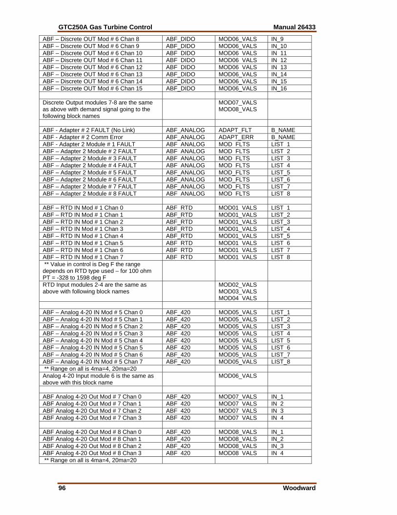
GTC250A Gas Turbine Control Manual 26433
96 Woodward
ABF – Discrete OUT Mod # 6 Chan 8 ABF_DIDO MOD06_VALS IN_9 ABF – Discrete OUT Mod # 6 Chan 9 ABF_DIDO MOD06_VALS IN_10 ABF – Discrete OUT Mod # 6 Chan 10 ABF DIDO MOD06 VALS IN 11 ABF – Discrete OUT Mod # 6 Chan 11 ABF DIDO MOD06 VALS IN 12 ABF – Discrete OUT Mod # 6 Chan 12 ABF DIDO MOD06 VALS IN 13 ABF – Discrete OUT Mod # 6 Chan 13 ABF_DIDO MOD06_VALS IN_14 ABF – Discrete OUT Mod # 6 Chan 14 ABF_DIDO MOD06_VALS IN_15 ABF – Discrete OUT Mod # 6 Chan 15 ABF_DIDO MOD06_VALS IN_16 Discrete Output modules 7-8 are the same as above with demand signal going to the following block names
MOD07_VALS MOD08_VALS
ABF - Adapter # 2 FAULT (No Link) ABF_ANALOG ADAPT_FLT B_NAME ABF - Adapter # 2 Comm Error ABF_ANALOG ADAPT_ERR B_NAME ABF - Adapter 2 Module # 1 FAULT ABF ANALOG MOD FLTS LIST 1 ABF – Adapter 2 Module # 2 FAULT ABF ANALOG MOD FLTS LIST 2 ABF – Adapter 2 Module # 3 FAULT ABF ANALOG MOD FLTS LIST 3 ABF – Adapter 2 Module # 4 FAULT ABF ANALOG MOD FLTS LIST 4 ABF – Adapter 2 Module # 5 FAULT ABF_ANALOG MOD_FLTS LIST_5 ABF – Adapter 2 Module # 6 FAULT ABF_ANALOG MOD_FLTS LIST_6 ABF – Adapter 2 Module # 7 FAULT ABF_ANALOG MOD_FLTS LIST_7 ABF – Adapter 2 Module # 8 FAULT ABF ANALOG MOD FLTS LIST 8 ABF – RTD IN Mod # 1 Chan 0 ABF RTD MOD01 VALS LIST 1 ABF – RTD IN Mod # 1 Chan 1 ABF_RTD MOD01_VALS LIST_2 ABF – RTD IN Mod # 1 Chan 2 ABF_RTD MOD01_VALS LIST_3 ABF – RTD IN Mod # 1 Chan 3 ABF_RTD MOD01_VALS LIST_4 ABF – RTD IN Mod # 1 Chan 4 ABF_RTD MOD01_VALS LIST_5 ABF – RTD IN Mod # 1 Chan 5 ABF RTD MOD01 VALS LIST 6 ABF – RTD IN Mod # 1 Chan 6 ABF RTD MOD01 VALS LIST 7 ABF – RTD IN Mod # 1 Chan 7 ABF RTD MOD01 VALS LIST 8 ** Value in control is Deg F the range depends on RTD type used – for 100 ohm PT = -328 to 1598 deg F
RTD Input modules 2-4 are the same as above with following block names
MOD02_VALS MOD03_VALS MOD04 VALS
ABF – Analog 4-20 IN Mod # 5 Chan 0 ABF_420 MOD05_VALS LIST_1 ABF – Analog 4-20 IN Mod # 5 Chan 1 ABF_420 MOD05_VALS LIST_2 ABF – Analog 4-20 IN Mod # 5 Chan 2 ABF_420 MOD05_VALS LIST_3 ABF – Analog 4-20 IN Mod # 5 Chan 3 ABF 420 MOD05 VALS LIST 4 ABF – Analog 4-20 IN Mod # 5 Chan 4 ABF 420 MOD05 VALS LIST 5 ABF – Analog 4-20 IN Mod # 5 Chan 5 ABF 420 MOD05 VALS LIST 6 ABF – Analog 4-20 IN Mod # 5 Chan 6 ABF_420 MOD05_VALS LIST_7 ABF – Analog 4-20 IN Mod # 5 Chan 7 ABF_420 MOD05_VALS LIST_8 ** Range on all is 4ma=4, 20ma=20 Analog 4-20 Input module 6 is the same as above with this block name
MOD06_VALS
ABF Analog 4-20 Out Mod # 7 Chan 0 ABF_420 MOD07_VALS IN_1 ABF Analog 4-20 Out Mod # 7 Chan 1 ABF 420 MOD07 VALS IN 2 ABF Analog 4-20 Out Mod # 7 Chan 2 ABF 420 MOD07 VALS IN 3 ABF Analog 4-20 Out Mod # 7 Chan 3 ABF 420 MOD07 VALS IN 4 ABF Analog 4-20 Out Mod # 8 Chan 0 ABF_420 MOD08_VALS IN_1 ABF Analog 4-20 Out Mod # 8 Chan 1 ABF_420 MOD08_VALS IN_2 ABF Analog 4-20 Out Mod # 8 Chan 2 ABF_420 MOD08_VALS IN_3 ABF Analog 4-20 Out Mod # 8 Chan 3 ABF 420 MOD08 VALS IN 4 ** Range on all is 4ma=4, 20ma=20
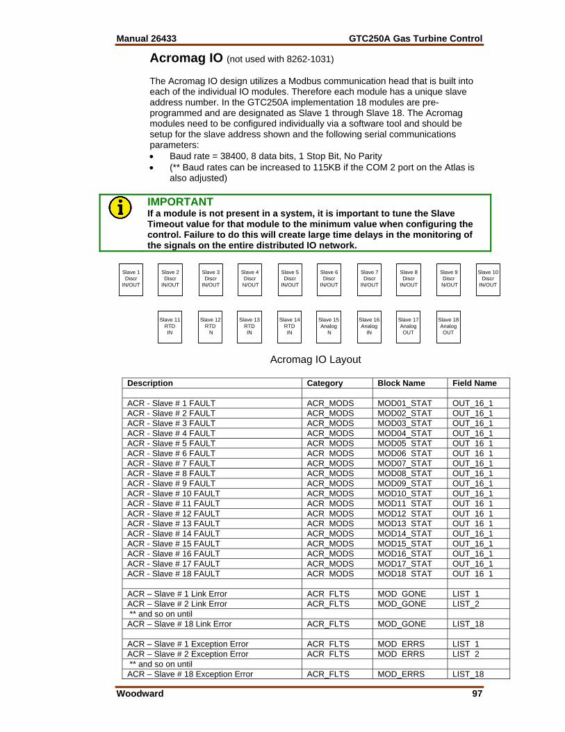
Manual 26433 GTC250A Gas Turbine Control
Woodward 97
Acromag IO (not used with 8262-1031) The Acromag IO design utilizes a Modbus communication head that is built into each of the individual IO modules. Therefore each module has a unique slave address number. In the GTC250A implementation 18 modules are pre-programmed and are designated as Slave 1 through Slave 18. The Acromag modules need to be configured individually via a software tool and should be setup for the slave address shown and the following serial communications parameters: • Baud rate = 38400, 8 data bits, 1 Stop Bit, No Parity • (** Baud rates can be increased to 115KB if the COM 2 port on the Atlas is
also adjusted)
IMPORTANT If a module is not present in a system, it is important to tune the Slave Timeout value for that module to the minimum value when configuring the control. Failure to do this will create large time delays in the monitoring of the signals on the entire distributed IO network.
Description Category Block Name Field Name ACR - Slave # 1 FAULT ACR_MODS MOD01_STAT OUT_16_1 ACR - Slave # 2 FAULT ACR_MODS MOD02_STAT OUT_16_1 ACR - Slave # 3 FAULT ACR_MODS MOD03_STAT OUT_16_1 ACR - Slave # 4 FAULT ACR_MODS MOD04_STAT OUT_16_1 ACR - Slave # 5 FAULT ACR MODS MOD05 STAT OUT 16 1 ACR - Slave # 6 FAULT ACR MODS MOD06 STAT OUT 16 1 ACR - Slave # 7 FAULT ACR_MODS MOD07_STAT OUT_16_1 ACR - Slave # 8 FAULT ACR_MODS MOD08_STAT OUT_16_1 ACR - Slave # 9 FAULT ACR_MODS MOD09_STAT OUT_16_1 ACR - Slave # 10 FAULT ACR_MODS MOD10_STAT OUT_16_1 ACR - Slave # 11 FAULT ACR MODS MOD11 STAT OUT 16 1 ACR - Slave # 12 FAULT ACR MODS MOD12 STAT OUT 16 1 ACR - Slave # 13 FAULT ACR MODS MOD13 STAT OUT 16 1 ACR - Slave # 14 FAULT ACR_MODS MOD14_STAT OUT_16_1 ACR - Slave # 15 FAULT ACR_MODS MOD15_STAT OUT_16_1 ACR - Slave # 16 FAULT ACR_MODS MOD16_STAT OUT_16_1 ACR - Slave # 17 FAULT ACR_MODS MOD17_STAT OUT_16_1 ACR - Slave # 18 FAULT ACR MODS MOD18 STAT OUT 16 1 ACR – Slave # 1 Link Error ACR FLTS MOD GONE LIST 1 ACR – Slave # 2 Link Error ACR_FLTS MOD_GONE LIST_2 ** and so on until ACR – Slave # 18 Link Error ACR_FLTS MOD_GONE LIST_18 ACR – Slave # 1 Exception Error ACR FLTS MOD ERRS LIST 1 ACR – Slave # 2 Exception Error ACR FLTS MOD ERRS LIST 2 ** and so on until ACR – Slave # 18 Exception Error ACR_FLTS MOD_ERRS LIST_18
Slave 1Discr
IN/OUT
Acromag IO Layout
Slave 2Discr
IN/OUT
Slave 3Discr
IN/OUT
Slave 4Discr
N/OUT
Slave 9DiscrN/OUT
Slave 10Discr
IN/OUT
Slave 5Discr
IN/OUT
Slave 6Discr
IN/OUT
Slave 7Discr
IN/OUT
Slave 8Discr
IN/OUT
Slave 11RTDIN
Slave 12RTD
N
Slave 13RTDIN
Slave 18AnalogOUT
Slave 14RTDIN
Slave 15Analog
N
Slave 16Analog
IN
Slave 17AnalogOUT
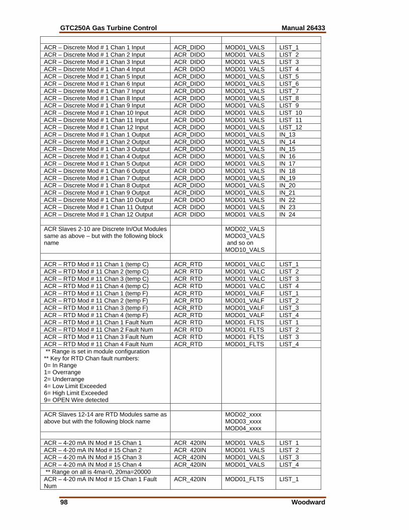
GTC250A Gas Turbine Control Manual 26433
98 Woodward
ACR – Discrete Mod # 1 Chan 1 Input ACR_DIDO MOD01_VALS LIST_1 ACR – Discrete Mod # 1 Chan 2 Input ACR DIDO MOD01 VALS LIST 2 ACR – Discrete Mod # 1 Chan 3 Input ACR DIDO MOD01 VALS LIST 3 ACR – Discrete Mod # 1 Chan 4 Input ACR DIDO MOD01 VALS LIST 4 ACR – Discrete Mod # 1 Chan 5 Input ACR_DIDO MOD01_VALS LIST_5 ACR – Discrete Mod # 1 Chan 6 Input ACR_DIDO MOD01_VALS LIST_6 ACR – Discrete Mod # 1 Chan 7 Input ACR_DIDO MOD01_VALS LIST_7 ACR – Discrete Mod # 1 Chan 8 Input ACR_DIDO MOD01_VALS LIST_8 ACR – Discrete Mod # 1 Chan 9 Input ACR DIDO MOD01 VALS LIST 9 ACR – Discrete Mod # 1 Chan 10 Input ACR DIDO MOD01 VALS LIST 10 ACR – Discrete Mod # 1 Chan 11 Input ACR DIDO MOD01 VALS LIST 11 ACR – Discrete Mod # 1 Chan 12 Input ACR_DIDO MOD01_VALS LIST_12 ACR – Discrete Mod # 1 Chan 1 Output ACR_DIDO MOD01_VALS IN_13 ACR – Discrete Mod # 1 Chan 2 Output ACR_DIDO MOD01_VALS IN_14 ACR – Discrete Mod # 1 Chan 3 Output ACR_DIDO MOD01_VALS IN_15 ACR – Discrete Mod # 1 Chan 4 Output ACR DIDO MOD01 VALS IN 16 ACR – Discrete Mod # 1 Chan 5 Output ACR DIDO MOD01 VALS IN 17 ACR – Discrete Mod # 1 Chan 6 Output ACR DIDO MOD01 VALS IN 18 ACR – Discrete Mod # 1 Chan 7 Output ACR_DIDO MOD01_VALS IN_19 ACR – Discrete Mod # 1 Chan 8 Output ACR_DIDO MOD01_VALS IN_20 ACR – Discrete Mod # 1 Chan 9 Output ACR_DIDO MOD01_VALS IN_21 ACR – Discrete Mod # 1 Chan 10 Output ACR DIDO MOD01 VALS IN 22 ACR – Discrete Mod # 1 Chan 11 Output ACR DIDO MOD01 VALS IN 23 ACR – Discrete Mod # 1 Chan 12 Output ACR DIDO MOD01 VALS IN 24 ACR Slaves 2-10 are Discrete In/Out Modules same as above – but with the following block name
MOD02_VALS MOD03_VALS and so on MOD10_VALS
ACR – RTD Mod # 11 Chan 1 (temp C) ACR_RTD MOD01_VALC LIST_1 ACR – RTD Mod # 11 Chan 2 (temp C) ACR RTD MOD01 VALC LIST 2 ACR – RTD Mod # 11 Chan 3 (temp C) ACR RTD MOD01 VALC LIST 3 ACR – RTD Mod # 11 Chan 4 (temp C) ACR RTD MOD01 VALC LIST 4 ACR – RTD Mod # 11 Chan 1 (temp F) ACR_RTD MOD01_VALF LIST_1 ACR – RTD Mod # 11 Chan 2 (temp F) ACR_RTD MOD01_VALF LIST_2 ACR – RTD Mod # 11 Chan 3 (temp F) ACR_RTD MOD01_VALF LIST_3 ACR – RTD Mod # 11 Chan 4 (temp F) ACR_RTD MOD01_VALF LIST_4 ACR – RTD Mod # 11 Chan 1 Fault Num ACR RTD MOD01 FLTS LIST 1 ACR – RTD Mod # 11 Chan 2 Fault Num ACR RTD MOD01 FLTS LIST 2 ACR – RTD Mod # 11 Chan 3 Fault Num ACR RTD MOD01 FLTS LIST 3 ACR – RTD Mod # 11 Chan 4 Fault Num ACR_RTD MOD01_FLTS LIST_4 ** Range is set in module configuration ** Key for RTD Chan fault numbers: 0= In Range 1= Overrange 2= Underrange 4= Low Limit Exceeded 6= High Limit Exceeded 9= OPEN Wire detected
ACR Slaves 12-14 are RTD Modules same as above but with the following block name
MOD02_xxxx MOD03_xxxx MOD04_xxxx
ACR – 4-20 mA IN Mod # 15 Chan 1 ACR 420IN MOD01 VALS LIST 1 ACR – 4-20 mA IN Mod # 15 Chan 2 ACR 420IN MOD01 VALS LIST 2 ACR – 4-20 mA IN Mod # 15 Chan 3 ACR_420IN MOD01_VALS LIST_3 ACR – 4-20 mA IN Mod # 15 Chan 4 ACR_420IN MOD01_VALS LIST_4 ** Range on all is 4ma=0, 20ma=20000 ACR – 4-20 mA IN Mod # 15 Chan 1 Fault Num
ACR_420IN MOD01_FLTS LIST_1
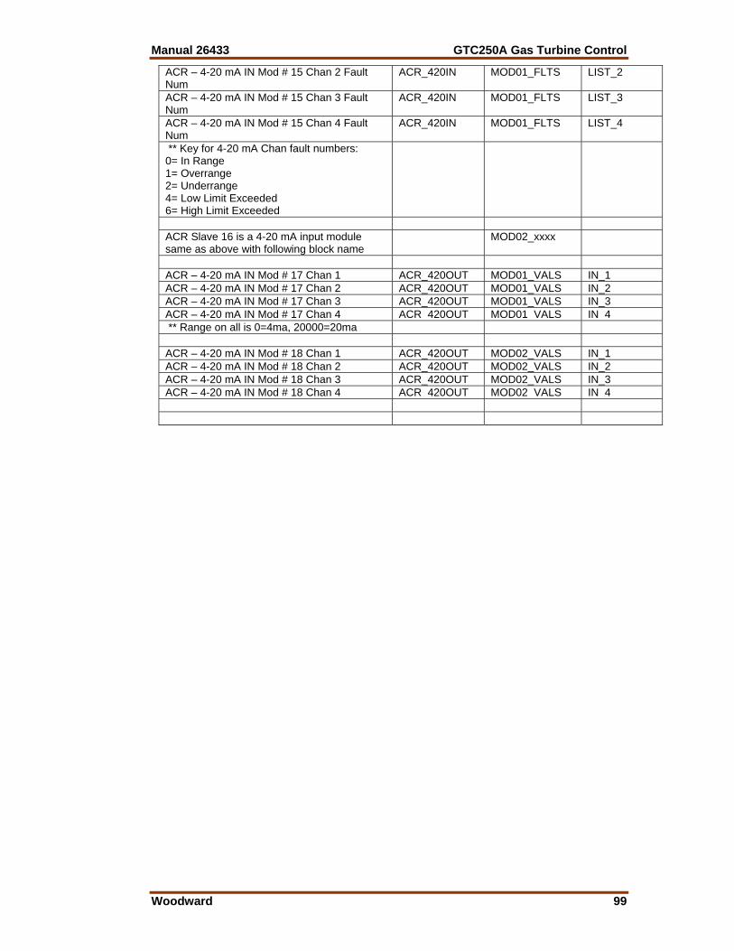
Manual 26433 GTC250A Gas Turbine Control
Woodward 99
ACR – 4-20 mA IN Mod # 15 Chan 2 Fault Num
ACR_420IN MOD01_FLTS LIST_2
ACR – 4-20 mA IN Mod # 15 Chan 3 Fault Num
ACR_420IN MOD01_FLTS LIST_3
ACR – 4-20 mA IN Mod # 15 Chan 4 Fault Num
ACR_420IN MOD01_FLTS LIST_4
** Key for 4-20 mA Chan fault numbers: 0= In Range 1= Overrange 2= Underrange 4= Low Limit Exceeded 6= High Limit Exceeded
ACR Slave 16 is a 4-20 mA input module same as above with following block name
MOD02_xxxx
ACR – 4-20 mA IN Mod # 17 Chan 1 ACR_420OUT MOD01_VALS IN_1 ACR – 4-20 mA IN Mod # 17 Chan 2 ACR_420OUT MOD01_VALS IN_2 ACR – 4-20 mA IN Mod # 17 Chan 3 ACR_420OUT MOD01_VALS IN_3 ACR – 4-20 mA IN Mod # 17 Chan 4 ACR 420OUT MOD01 VALS IN 4 ** Range on all is 0=4ma, 20000=20ma ACR – 4-20 mA IN Mod # 18 Chan 1 ACR_420OUT MOD02_VALS IN_1 ACR – 4-20 mA IN Mod # 18 Chan 2 ACR_420OUT MOD02_VALS IN_2 ACR – 4-20 mA IN Mod # 18 Chan 3 ACR_420OUT MOD02_VALS IN_3 ACR – 4-20 mA IN Mod # 18 Chan 4 ACR 420OUT MOD02 VALS IN 4

We appreciate your comments about the content of our publications.
Send comments to: [email protected]
Please reference publication 26433.
PO Box 1519, Fort Collins CO 80522-1519, USA 1000 East Drake Road, Fort Collins CO 80525, USA Phone +1 (970) 482-5811 • Fax +1 (970) 498-3058
Email and Website—www.woodward.com
Woodward has company-owned plants, subsidiaries, and branches, as well as authorized distributors and other authorized service and sales facilities throughout the world.
Complete address / phone / fax / email information for all locations is available on our website.
2009/4/Fort Collins