Embed Size (px)
Citation preview
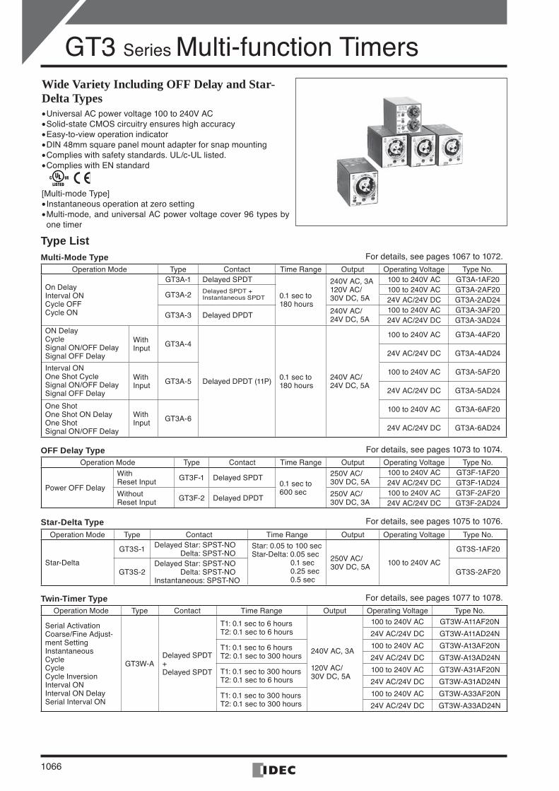
GT3 Series Multi-function Timers
1066
Wide Variety Including OFF Delay and Star-Delta TypesUniversal AC power voltage 100 to 240V ACSolid-state CMOS circuitry ensures high accuracyEasy-to-view operation indicator DIN 48mm square panel mount adapter for snap mounting Complies with safety standards. UL/c-UL listed. Complies with EN standard
[Multi-mode Type]Instantaneous operation at zero settingMulti-mode, and universal AC power voltage cover 96 types by one timer
••••••
••
Type ListMulti-Mode Type For details, see pages 1067 to 1072.
Operation Mode Type Contact Time Range Output Operating Voltage Type No.
On DelayInterval ONCycle OFFCycle ON
GT3A-1 Delayed SPDT
0.1 sec to 180 hours
240V AC, 3A120V AC/ 30V DC, 5A
100 to 240V AC GT3A-1AF20
GT3A-2 Delayed SPDT + Instantaneous SPDT
100 to 240V AC GT3A-2AF2024V AC/24V DC GT3A-2AD24
GT3A-3 Delayed DPDT 240V AC/ 24V DC, 5A
100 to 240V AC GT3A-3AF2024V AC/24V DC GT3A-3AD24
ON Delay CycleSignal ON/OFF DelaySignal OFF Delay
With Input GT3A-4
Delayed DPDT (11P) 0.1 sec to 180 hours
240V AC/ 24V DC, 5A
100 to 240V AC GT3A-4AF20
24V AC/24V DC GT3A-4AD24
Interval ONOne Shot Cycle Signal ON/OFF Delay Signal OFF Delay
With Input GT3A-5
100 to 240V AC GT3A-5AF20
24V AC/24V DC GT3A-5AD24
One Shot One Shot ON DelayOne Shot Signal ON/OFF Delay
With Input GT3A-6
100 to 240V AC GT3A-6AF20
24V AC/24V DC GT3A-6AD24
OFF Delay Type For details, see pages 1073 to 1074.
Operation Mode Type Contact Time Range Output Operating Voltage Type No.
Power OFF Delay
With Reset Input GT3F-1 Delayed SPDT
0.1 sec to 600 sec
250V AC/30V DC, 5A
100 to 240V AC GT3F-1AF2024V AC/24V DC GT3F-1AD24
Without Reset Input GT3F-2 Delayed DPDT 250V AC/
30V DC, 3A100 to 240V AC GT3F-2AF2024V AC/24V DC GT3F-2AD24
Star-Delta Type For details, see pages 1075 to 1076.
Operation Mode Type Contact Time Range Output Operating Voltage Type No.
Star-Delta
GT3S-1 Delayed Star: SPST-NO Delta: SPST-NO
Star: 0.05 to 100 secStar-Delta: 0.05 sec 0.1 sec 0.25 sec 0.5 sec
250V AC/30V DC, 5A 100 to 240V AC
GT3S-1AF20
GT3S-2Delayed Star: SPST-NO Delta: SPST-NOInstantaneous: SPST-NO
GT3S-2AF20
Twin-Timer Type For details, see pages 1077 to 1078.
Operation Mode Type Contact Time Range Output Operating Voltage Type No.
Serial ActivationCoarse/Fine Adjust- ment Setting Instantaneous CycleCycleCycle Inversion Interval ONInterval ON Delay Serial Interval ON
GT3W-A Delayed SPDT + Delayed SPDT
T1: 0.1 sec to 6 hoursT2: 0.1 sec to 6 hours
240V AC, 3A
120V AC/ 30V DC, 5A
100 to 240V AC GT3W-A11AF20N
24V AC/24V DC GT3W-A11AD24N
T1: 0.1 sec to 6 hoursT2: 0.1 sec to 300 hours
100 to 240V AC GT3W-A13AF20N
24V AC/24V DC GT3W-A13AD24N
T1: 0.1 sec to 300 hoursT2: 0.1 sec to 6 hours
100 to 240V AC GT3W-A31AF20N
24V AC/24V DC GT3W-A31AD24N
T1: 0.1 sec to 300 hoursT2: 0.1 sec to 300 hours
100 to 240V AC GT3W-A33AF20N
24V AC/24V DC GT3W-A33AD24N
IDEC1066-1085.indd 1066IDEC1066-1085.indd 1066 07.8.17 4:09:54 PM07.8.17 4:09:54 PM
GT3 Series [Multi-Mode Type]
ControlUnits
Display Lights
DisplayUnits
SafetyProducts
TerminalBlocks
Comm.Terminals
AS-Interface
Relays & Timers
Sockets
Circuit Protectors
Power Supplies
PLCs & SmartRelay
Operator Interfaces
Sensors
Control Stations
Explosion Protection
References
FlushSilhouette
1067
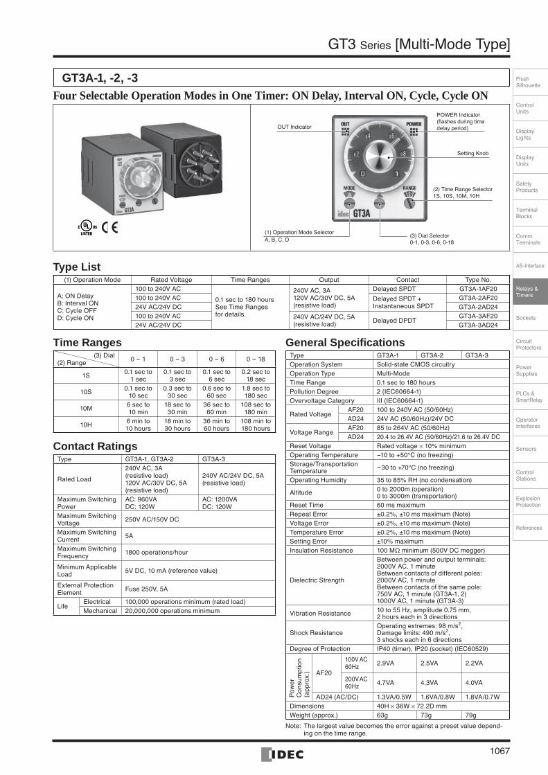
GT3A-1, -2, -3Four Selectable Operation Modes in One Timer: ON Delay, Interval ON, Cycle, Cycle ON
(3) Dial Selector0-1, 0-3, 0-6, 0-18
OUT Indicator
POWER Indicator(flashes during time delay period)
Setting Knob
(1) Operation Mode SelectorA, B, C, D
(2) Time Range Selector1S, 10S, 10M, 10H
Type List (1) Operation Mode Rated Voltage Time Ranges Output Contact Type No.
A: ON Delay B: Interval ON C: Cycle OFFD: Cycle ON
100 to 240V AC
0.1 sec to 180 hoursSee Time Ranges for details.
240V AC, 3A120V AC/30V DC, 5A(resistive load)
Delayed SPDT GT3A-1AF20100 to 240V AC Delayed SPDT +
Instantaneous SPDTGT3A-2AF20
24V AC/24V DC GT3A-2AD24100 to 240V AC 240V AC/24V DC, 5A
(resistive load) Delayed DPDTGT3A-3AF20
24V AC/24V DC GT3A-3AD24
General SpecificationsType GT3A-1 GT3A-2 GT3A-3Operation System Solid-state CMOS circuitry Operation Type Multi-ModeTime Range 0.1 sec to 180 hoursPollution Degree 2 (IEC60664-1)Overvoltage Category III (IEC60664-1)
Rated Voltage AF20 100 to 240V AC (50/60Hz)AD24 24V AC (50/60Hz)/24V DC
Voltage RangeAF20 85 to 264V AC (50/60Hz)AD24 20.4 to 26.4V AC (50/60Hz)/21.6 to 26.4V DC
Reset Voltage Rated voltage × 10% minimumOperating Temperature -10 to +50°C (no freezing) Storage/Transportation Temperature -30 to +70°C (no freezing)
Operating Humidity 35 to 85% RH (no condensation)
Altitude 0 to 2000m (operation) 0 to 3000m (transportation)
Reset Time 60 ms maximumRepeat Error ±0.2%, ±10 ms maximum (Note) Voltage Error ±0.2%, ±10 ms maximum (Note) Temperature Error ±0.2%, ±10 ms maximum (Note) Setting Error ±10% maximumInsulation Resistance 100 MΩ minimum (500V DC megger)
Dielectric Strength
Between power and output terminals: 2000V AC, 1 minuteBetween contacts of different poles: 2000V AC, 1 minuteBetween contacts of the same pole: 750V AC, 1 minute (GT3A-1, 2)1000V AC, 1 minute (GT3A-3)
Vibration Resistance 10 to 55 Hz, amplitude 0.75 mm, 2 hours each in 3 directions
Shock ResistanceOperating extremes: 98 m/s2, Damage limits: 490 m/s2,3 shocks each in 6 directions
Degree of Protection IP40 (timer), IP20 (socket) (IEC60529)
Pow
er
Con
sum
ptio
n (a
ppr
ox.) AF20
100V AC60Hz 2.9VA 2.5VA 2.2VA
200VAC60Hz 4.7VA 4.3VA 4.0VA
AD24 (AC/DC) 1.3VA/0.5W 1.6VA/0.8W 1.8VA/0.7WDimensions 40H × 36W × 72.2D mmWeight (approx.) 63g 73g 79g
Note: The largest value becomes the error against a preset value depend-ing on the time range.
Time Ranges(3) Dial
(2) Range 0 - 1 0 - 3 0 - 6 0 - 18
1S 0.1 sec to 1 sec
0.1 sec to 3 sec
0.1 sec to 6 sec
0.2 sec to 18 sec
10S 0.1 sec to 10 sec
0.3 sec to 30 sec
0.6 sec to 60 sec
1.8 sec to 180 sec
10M 6 sec to 10 min
18 sec to 30 min
36 sec to 60 min
108 sec to 180 min
10H 6 min to 10 hours
18 min to 30 hours
36 min to 60 hours
108 min to 180 hours
Contact RatingsType GT3A-1, GT3A-2 GT3A-3
Rated Load
240V AC, 3A (resistive load)120V AC/30V DC, 5A (resistive load)
240V AC/24V DC, 5A (resistive load)
Maximum Switching Power
AC: 960VADC: 120W
AC: 1200VADC: 120W
Maximum Switching Voltage 250V AC/150V DC
Maximum Switching Current 5A
Maximum Switching Frequency 1800 operations/hour
Minimum Applicable Load 5V DC, 10 mA (reference value)
External Protection Element Fuse 250V, 5A
LifeElectrical 100,000 operations minimum (rated load) Mechanical 20,000,000 operations minimum
IDEC1066-1085.indd 1067IDEC1066-1085.indd 1067 07.8.17 4:09:56 PM07.8.17 4:09:56 PM
GT3 Series [Multi-Mode Type]
1068
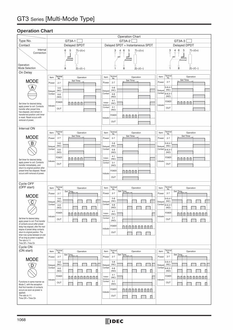
Operation ChartOperation Chart
Type No. GT3A-1 GT3A-2 GT3A-3Contact Delayed SPDT Delayed SPDT + Instantaneous SPDT Delayed DPDT
7(~)/(+)
2(~)/(-)
56
8
7(~)/(+)
2(~)/(-)
3 4
1
56
8
7(~)/(+)
2(~)/(-)
3 4
1
56
8
On Delay
MODEA
Set timer for desired delay, apply power to coil. Contacts transfer after preset time has elapsed, and remain in transferred position until timer is reset. Reset occurs with removal of power.
Item Operation
Power
DelayedContact
Indicator
2-7
5-8(NC)
6-8(NO)
POWER
OUT
Set Time
erminalTTNo.
TerminalNo.
4-1(NC)
3-1(NO)
Item TerminalNo. Operation
Power
DelayedContact
Instan-taneousContact
Indicator
2-7
5-8(NC)
6-8(NO)
POWER
OUT
Set Time
Item Operation
Power
DelayedContact
Indicator
2-7
5-8,4-1(NC)
6-8,3-1(NO)
POWER
OUT
Set Time
TerminalNo.
Interval ON
MODEB
Set timer for desired delay, apply power to coil. Contacts transfer immediately, and return to original position after preset time has elapsed. Reset occurs with removal of power.
Item Operation
Power
DelayedContact
Indicator
2-7
5-8(NC)
6-8(NO)
POWER
OUT
Set Time
TerminalNo.
4-1(NC)
3-1(NO)
Item TerminalNo. Operation
Power
DelayedContact
Instan-taneousContact
Indicator
2-7
5-8(NC)
6-8(NO)
POWER
OUT
Set Time
Item Operation
Power
DelayedContact
Indicator
2-7
5-8,4-1(NC)
6-8,3-1(NO)
POWER
OUT
Set Time
TerminalNo.
Cycle OFF(OFF start)
MODEC
Set timer for desired delay, apply power to coil. First transfer of contacts occurs after preset delay has elapsed, after the next elapse of preset delay contacts return to original position. The timer now cycles between on and off as long as power is applied. The ratio is 1:1. Time Off = Time On
Item Operation
Power
DelayedContact
Indicator
2-7
5-8(NC)
6-8(NO)
POWER
OUT
Set Time
TerminalNo.
4-1(NC)
3-1(NO)
Item TerminalNo. Operation
Power
DelayedContact
Instan-taneousContact
Indicator
2-7
5-8(NC)
6-8(NO)
POWER
OUT
Set Time
Item Operation
Power
DelayedContact
Indicator
2-7
5-8,4-1(NC)
6-8,3-1(NO)
POWER
OUT
Set Time
TerminalNo.
Cycle ON(ON start)
MODED
Functions in same manner as Mode C, with the exception that first transfer of contacts occurs as soon as power is applied. The ratio is 1:1. Time Off = Time On
Item Operation
Power
DelayedContact
Indicator
2-7
5-8(NC)
6-8(NO)
POWER
OUT
Set Time
TerminalNo.
4-1(NC)
3-1(NO)
Item TerminalNo. Operation
Power
DelayedContact
Instan-taneousContact
Indicator
2-7
5-8(NC)
6-8(NO)
POWER
OUT
Set Time
Item Operation
Power
DelayedContact
Indicator
2-7
5-8,4-1(NC)
6-8,3-1(NO)
POWER
OUT
Set Time
TerminalNo.
Operation Mode Selection
InternalConnection
IDEC1066-1085.indd 1068IDEC1066-1085.indd 1068 07.8.17 4:09:57 PM07.8.17 4:09:57 PM
ControlUnits
Display Lights
DisplayUnits
SafetyProducts
TerminalBlocks
Comm.Terminals
AS-Interface
Relays & Timers
Sockets
Circuit Protectors
Power Supplies
PLCs & SmartRelay
Operator Interfaces
Sensors
Control Stations
Explosion Protection
References
FlushSilhouette
1069
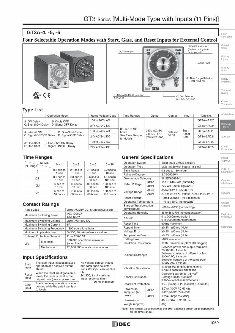
GT3 Series [Multi-Mode Type with Inputs (11 Pins)]
GT3A-4, -5, -6 Four Selectable Operation Modes with Start, Gate, and Reset Inputs for External Control
(3) Dial Selector0-1, 0-3, 0-6, 0-18
LED OUT Indicator
POWER Indicator(flashes during time delay period)
Setting Knob
(1) Operation Mode SelectorA, B, C, D
(2) Time Range Selector1S, 10S, 10M, 10H
Type List (1) Operation Mode Rated Voltage Code Time Ranges Output Contact Input Type No.
A: ON Delay B: Cycle OFF C: Signal ON Delay D: Signal OFF Delay
100 to 240V AC
0.1 sec to 180 hoursSee Time Ranges for details
240V AC, 5A24V DC, 5A (resistive load)
Delayed DPDT
StartResetGate
GT3A-4AF20
24V AC/24V DC GT3A-4AD24
A: Interval ON B: One-Shot Cycle, C: Signal ON/OFF Delay D: Signal OFF Delay
100 to 240V AC GT3A-5AF20
24V AC/24V DC GT3A-5AD24
A: One-Shot B: One-Shot ON Delay C: One-Shot D: Signal ON/OFF Delay
100 to 240V AC GT3A-6AF20
24V AC/24V DC GT3A-6AD24
Time Ranges(3) Dial
(2) Range 0 - 1 0 - 3 0 - 6 0 - 18
1S 0.1 sec to 1 sec
0.1 sec to 3 sec
0.1 sec to 6 sec
0.2 sec to 18 sec
10S 0.1 sec to 10 sec
0.3 sec to 30 sec
0.6 sec to 60 sec
1.8 sec to 180 sec
10M 6 sec to 10 min
18 sec to 30 min
36 sec to 60 min
108 sec to 180 min
10H 6 min to 10 hours
18 min to 30 hours
36 min to 60 hours
108 min to 180 hours
Contact RatingsRated Load 240V AC/24V DC, 5A (resistive load)
Maximum Switching Power AC: 1200VADC: 120W
Maximum Switching Voltage 250V AC/150V DCMaximum Switching Current 5A Maximum Switching Frequency 1800 operations/hourMinimum Applicable Load 5V DC, 10 mA (reference value) External Protection Element Fuse 250V, 5A
LifeElectrical 100,000 operations minimum
(rated load) Mechanical 20,000,000 operations minimum
Input SpecificationsStart Input
The start input initiates delayed operation and controls output status.
No-voltage contact inputs and NPN open collector transistor inputs are applica-ble. 24V DC, 1 mA maximumInput response time: 50 ms maximum
Reset Input
When the reset input goes on (L level), the timer is reset to the original time (time at power-on).
Gate Input
The time delay operation is sus-pended while the gate input is on (L level).
General SpecificationsOperation System Solid-state CMOS circuitry Operation Type Multi-mode with inputs (11 pins) Time Range 0.1 sec to 180 hoursPollution Degree 2 (IEC60664-1)Overvoltage Category III (IEC60664-1)
Rated Voltage AF20 100 to 240V AC (50/60Hz)AD24 24V AC (50/60Hz)/24V DC
Voltage RangeAF20 85 to 264V AC (50/60Hz)AD24 20.4 to 26.4V AC (50/60Hz)/21.6 to 26.4V DC
Reset Voltage Rated voltage × 10% minimumOperating Temperature -10 to +50°C (no freezing) Storage/Transportation Temperature -30 to +70°C (no freezing)
Operating Humidity 35 to 85% RH (no condensation)
Altitude 0 to 2000m (operation) 0 to 3000m (transportation)
Reset Time 60 ms maximumRepeat Error ±0.2%, ±10 ms (Note) Voltage Error ±0.2%, ±10 ms (Note) Temperature Error ±0.2%, ±10 ms (Note) Setting Error ±10% maximumInsulation Resistance 100MΩ minimum (500V DC megger)
Dielectric Strength
Between power and output terminals: 2000V AC, 1 minuteBetween contacts of different poles: 2000V AC, 1 minuteBetween contacts of the same pole: 1000V AC, 1 minute
Vibration Resistance 10 to 55 Hz, amplitude 0.75 mm, 2 hours each in 3 directions
Shock ResistanceOperating extremes: 98 m/s2 Damage limits: 490 m/s2
3 shocks each in 6 directionsDegree of Protection IP40 (timer), IP20 (socket) (IEC60529)
Power Con-sumption (Ap-prox.)
AF20 2.2VA (100V AC/60Hz),4.1VA (200V AC/60Hz)
AD24 1.8VA (AC)/0.7W (DC)Dimensions 40H × 36W × 72.2D mm Weight (approx.) 80g
Note: The largest value becomes the error against a preset value depending on the time range.
IDEC1066-1085.indd 1069IDEC1066-1085.indd 1069 07.8.17 4:10:00 PM07.8.17 4:10:00 PM
1070
GT3 Series [Multi-Mode Type with Inputs (11 Pins)]
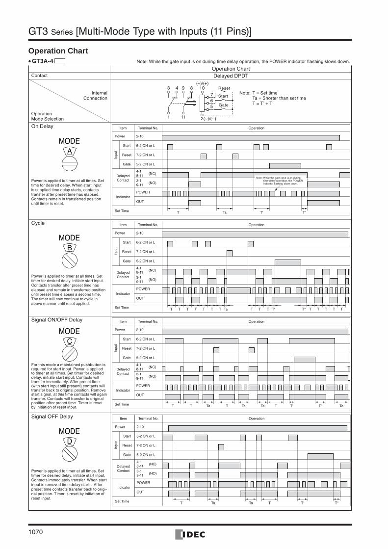
Operation ChartGT3A-4 Note: While the gate input is on during time delay operation, the POWER indicator flashing slows down.
Operation ChartContact Delayed DPDT
On Delay
MODEA
Power is applied to timer at all times. Set time for desired delay. When start input is supplied time delay starts, contacts transfer after preset time has elapsed. Contacts remain in transferred position until timer is reset.
Item Terminal No. Operation
Power 2-10
6-2 ON or LStart
Reset
Gate
7-2 ON or L
5-2 ON or L
Inpu
t
DelayedContact
Indicator
Set Time
POWER
OUT
4-18-11 (NC)
3-19-11 (NO)
T Ta T' T"
Note: While the gate input is on during time-delay operation, the POWER indicator flashing slows down.
Cycle
MODEB
Power is applied to timer at all times. Set timer for desired delay, initiate start input. Contacts transfer after preset time has elapsed and remain in transferred position until preset time elapses a second time. The timer will now continue to cycle in above manner until reset applied.
T T T T T T T Ta T T T T' T T T T TT"
Item Terminal No. Operation
Power 2-10
6-2 ON or LStart
Reset
Gate
7-2 ON or L
5-2 ON or L
Inpu
t
DelayedContact
Indicator
Set Time
POWER
OUT
4-18-11 (NC)
3-19-11 (NO)
Signal ON/OFF Delay
MODEC
For this mode a maintained pushbutton is required for start input. Power is applied to timer at all times. Set timer for desired delay, initiate start input. Contacts will transfer immediately. After preset time (with start input still present) contacts will transfer back to original position. Remove start signal, at this time contacts will again transfer. Contacts will transfer to original position after preset time. Timer is reset by initiation of reset input. T TaT T Ta Ta TaT T' T"
Item Terminal No. Operation
Power 2-10
6-2 ON or LStart
Reset
Gate
7-2 ON or L
5-2 ON or L
Inpu
t
DelayedContact
Indicator
Set Time
POWER
OUT
4-18-11 (NC)
3-19-11 (NO)
Signal OFF Delay
MODED
Power is applied to timer at all times. Set timer for desired delay, initiate start input. Contacts immediately transfer. When start input is removed time delay starts. After preset time contacts transfer back to origi-nal position. Timer is reset by initiation of reset input.
T Ta T' T"Ta T
Item Terminal No. Operation
Power 2-10
6-2 ON or LStart
Reset
Gate
7-2 ON or L
5-2 ON or L
Inpu
t
DelayedContact
Indicator
Set Time
POWER
OUT
4-18-11 (NC)
3-19-11 (NO)
•
Note: T = Set time Ta = Shorter than set time T = T’ + T’’
Operation Mode Selection
InternalConnection
7103 4
1
8
5
2(~)/(-)
6
9
11
Gate
Start
Reset(~)/(+)
IDEC1066-1085.indd 1070IDEC1066-1085.indd 1070 07.8.17 4:10:02 PM07.8.17 4:10:02 PM
ControlUnits
Display Lights
DisplayUnits
SafetyProducts
TerminalBlocks
Comm.Terminals
AS-Interface
Relays & Timers
Sockets
Circuit Protectors
Power Supplies
PLCs & SmartRelay
Operator Interfaces
Sensors
Control Stations
Explosion Protection
References
FlushSilhouette
1071
GT3 Series [Multi-Mode Type with Inputs (11 Pins)]
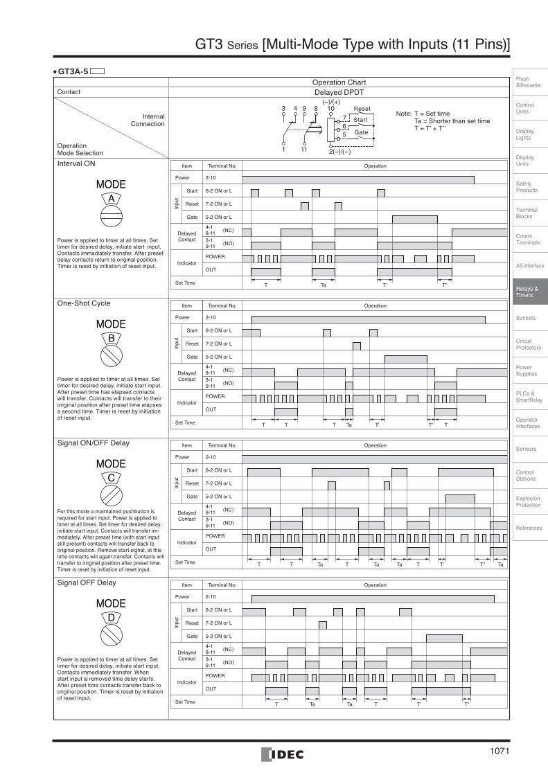
GT3A-5
Operation ChartContact Delayed DPDT
7103 4
1
8
5
2(~)/(-)
6
9
11
Gate
Start
Reset(~)/(+)
Interval ON
MODEA
Power is applied to timer at all times. Set timer for desired delay, initiate start input. Contacts immediately transfer. After preset delay contacts return to original position. Timer is reset by initiation of reset input.
T Ta T' T"
Item Terminal No. Operation
Power 2-10
6-2 ON or LStart
Reset
Gate
7-2 ON or L
5-2 ON or L
Inpu
t
DelayedContact
Indicator
Set Time
POWER
OUT
4-18-11 (NC)
3-19-11 (NO)
One-Shot Cycle
MODEB
Power is applied to timer at all times. Set timer for desired delay, initiate start input. After preset time has elapsed contacts will transfer. Contacts will transfer to their original position after preset time elapses a second time. Timer is reset by initiation of reset input.
T Ta T' T" TT T
Item Terminal No. Operation
Power 2-10
6-2 ON or LStart
Reset
Gate
7-2 ON or L
5-2 ON or L
Inpu
t
DelayedContact
Indicator
Set Time
POWER
OUT
4-18-11 (NC)
3-19-11 (NO)
Signal ON/OFF Delay
MODEC
For this mode a maintained pushbutton is required for start input. Power is applied to timer at all times. Set timer for desired delay, initiate start input. Contacts will transfer im-mediately. After preset time (with start input still present) contacts will transfer back to original position. Remove start signal, at this time contacts will again transfer. Contacts will transfer to original position after preset time. Timer is reset by initiation of reset input.
T Ta T'T T TaT"TTaTa
Item Terminal No. Operation
Power 2-10
6-2 ON or LStart
Reset
Gate
7-2 ON or L
5-2 ON or L
Inpu
t
DelayedContact
Indicator
Set Time
POWER
OUT
4-18-11 (NC)
3-19-11 (NO)
Signal OFF Delay
MODED
Power is applied to timer at all times. Set timer for desired delay, initiate start input. Contacts immediately transfer. When start input is removed time delay starts. After preset time contacts transfer back to original position. Timer is reset by initiation of reset input.
Ta T"T'T TTa
Item Terminal No. Operation
Power 2-10
6-2 ON or LStart
Reset
Gate
7-2 ON or L
5-2 ON or L
Inpu
t
DelayedContact
Indicator
Set Time
POWER
OUT
4-18-11 (NC)
3-19-11 (NO)
•
Note: T = Set time Ta = Shorter than set time T = T’ + T’’
Operation Mode Selection
InternalConnection
IDEC1066-1085.indd 1071IDEC1066-1085.indd 1071 07.8.17 4:10:03 PM07.8.17 4:10:03 PM
1072
GT3 Series [Multi-Mode Type with Inputs (11 Pins)]
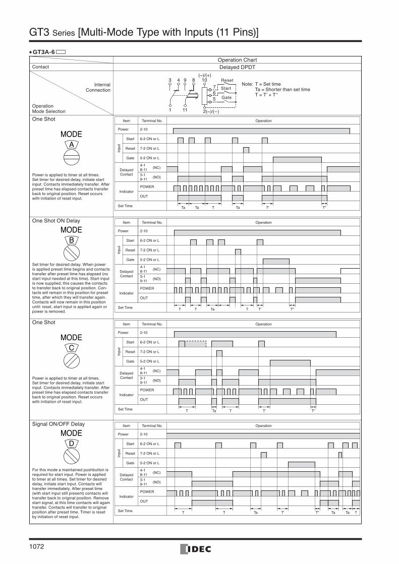
GT3A-6Operation Chart
Contact Delayed DPDT
One Shot
MODEA
Power is applied to timer at all times. Set timer for desired delay, initiate start input. Contacts immediately transfer. After preset time has elapsed contacts transfer back to original position. Reset occurs with initiation of reset input.
TTa T"T'TaTa
Item Terminal No. Operation
Power 2-10
6-2 ON or LStart
Reset
Gate
7-2 ON or L
5-2 ON or L
Inpu
t
DelayedContact
Indicator
Set Time
POWER
OUT
4-18-11 (NC)
3-19-11 (NO)
One Shot ON Delay
MODEB
Set timer for desired delay. When power is applied preset time begins and contacts transfer after preset time has elapsed (no start input needed at this time). Start input is now supplied, this causes the contacts to transfer back to original position. Con-tacts will remain in this position for preset time, after which they will transfer again. Contacts will now remain in this position until: reset, start input is applied again or power is removed. T T"T'TaT T
Item Terminal No. Operation
Power 2-10
6-2 ON or LStart
Reset
Gate
7-2 ON or L
5-2 ON or L
Inpu
t
DelayedContact
Indicator
Set Time
POWER
OUT
4-18-11 (NC)
3-19-11 (NO)
One Shot
MODEC
Power is applied to timer at all times. Set timer for desired delay, initiate start input. Contacts immediately transfer. After preset time has elapsed contacts transfer back to original position. Reset occurs with initiation of reset input.
T"T'TaT T
Item Terminal No. Operation
Power 2-10
6-2 ON or LStart
Reset
Gate
7-2 ON or L
5-2 ON or L
Inpu
t
DelayedContact
Indicator
Set Time
POWER
OUT
4-18-11 (NC)
3-19-11 (NO)
Signal ON/OFF Delay
MODED
For this mode a maintained pushbutton is required for start input. Power is applied to timer at all times. Set timer for desired delay, initiate start input. Contacts will transfer immediately. After preset time (with start input still present) contacts will transfer back to original position. Remove start signal, at this time contacts will again transfer. Contacts will transfer to original position after preset time. Timer is reset by initiation of reset input.
T"T'T T TTa TaTa
Item Terminal No. Operation
Power 2-10
6-2 ON or LStart
Reset
Gate
7-2 ON or L
5-2 ON or L
Inpu
t
DelayedContact
Indicator
Set Time
POWER
OUT
4-18-11 (NC)
3-19-11 (NO)
•
Note: T = Set time Ta = Shorter than set time T = T’ + T’’
Operation Mode Selection
InternalConnection
7103 4
1
8
5
2(~)/(-)
6
9
11
Gate
Start
Reset(~)/(+)
IDEC1066-1085.indd 1072IDEC1066-1085.indd 1072 07.8.17 4:10:04 PM07.8.17 4:10:04 PM
ControlUnits
Display Lights
DisplayUnits
SafetyProducts
TerminalBlocks
Comm.Terminals
AS-Interface
Relays & Timers
Sockets
Circuit Protectors
Power Supplies
PLCs & SmartRelay
Operator Interfaces
Sensors
Control Stations
Explosion Protection
References
FlushSilhouette
1073
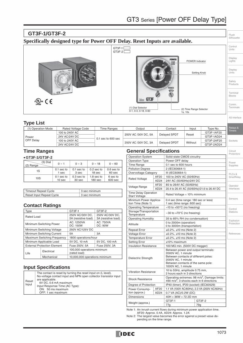
GT3 Series [Power OFF Delay Type]
GT3F-1/GT3F-2 Specifically designed type for Power OFF Delay. Reset Inputs are available.
GT3F-1GT3F-2
(2) Time Range Selector1s, 10s
POWER Indicator
Setting Knob
(1) Dial Selector0-1, 0-3, 0-18, 0-60
Type List (1) Operation Mode Rated Voltage Code Time Ranges Output Contact Input Type No.
PowerOFF Delay
100 to 240V AC
0.1 sec to 600 sec250V AC /30V DC, 5A Delayed SPDT Reset
GT3F-1AF2024V AC/24V DC GT3F-1AD24100 to 240V AC
250V AC /30V DC, 3A Delayed DPDT WithoutGT3F-2AF20
24V AC/24V DC GT3F-2AD24
Time RangesGT3F-1/GT3F-2
(3) Dial (2) Range 0 - 1 0 - 3 0 - 18 0 - 60
1S 0.1 sec to 1 sec
0.1 sec to 3 sec
0.2 sec to 18 sec
0.6 sec to 60 sec
10S 0.1 sec to 10 sec
0.3 sec to 30 sec
1.8 sec to 180 sec
6 sec to 600 sec
Timeout Repeat Cycle 3 sec minimumReset Input Repeat Cycle 3 sec minimum
Contact RatingsType GT3F-1 GT3F-2
Rated Load 250V AC/30V DC, 5A (resistive load)
250V AC/30V DC, 3A (resistive load)
Minimum Switching Power AC: 1250VADC: 150W
AC: 750VADC: 90W
Minimum Switching Voltage 250V AC/125V DCMinimum Switching Current 5A 3AMaximum Switching Frequency 1800 operations/hourMinimum Applicable Load 5V DC, 10 mA 5V DC, 100 mAExternal Protection Element Fuse 250V, 5A Fuse 250V, 3A
LifeElectrical 100,000 operations minimum
(rated load) Mechanical 10,000,000 operations minimum
Input Specifications
Reset Input
The contact is reset by turning the reset input on (L level).No-voltage contact input and NPN open collector transistor input are applicable. 6V DC, 0.6 mA maximumInput Response Time (AC Type): ON: 50 ms maximum OFF: 1 sec maximum
•
General SpecificationsOperation System Solid-state CMOS circuitry Operation Type Power OFF delay Time Range 0.1 sec to 600 hoursPollution Degree 2 (IEC60664-1)Overvoltage Category III (IEC60664-1)
Rated Voltage AF20 100 to 240V AC (50/60Hz)AD24 24V AC (50/60Hz)/24V DC
Voltage RangeAF20 85 to 264V AC (50/60Hz)AD24 20.4 to 26.4V AC (50/60Hz)/21.6 to 26.4V DC
Time Delay Operation Start Voltage Rated Voltage × 10% minimum
Minimum Power Applica-tion Time (Note 1)
0.4 sec (time range: 180 sec or less)1 sec (time range: 600 sec)
Operating Temperature -10 to +50°C (no freezing) Storage/Transportation Temperature -30 to +70°C (no freezing)
Operating Humidity 35 to 85% RH (no condensation)
Altitude 0 to 2000m (operation) 0 to 3000m (transportation)
Repeat Error ±0.2%, ±10 ms (Note 2) Voltage Error ±0.2%, ±10 ms (Note 2) Temperature Error ±0.2%, ±10 ms (Note 2) Setting Error ±10% maximumInsulation Resistance 100 MΩ min. (500V DC megger)
Dielectric Strength
Between power and output terminals: 2000V AC, 1 minuteBetween contacts of different poles:2000V AC, 1 minuteBetween contacts of the same pole: 1000V AC, 1 minute
Vibration Resistance 10 to 55Hz, amplitude 0.75 mm, 2 hours each in 3 directions
Shock Resistance Operating extremes: 98 m/s2, Damage limits: 490 m/s2, 3 shocks each in 6 directions
Degree of Protection IP40 (timer), IP20 (socket) (IEC60529)
Power Consump-tion (approx.)
AF20 1.1 VA (100V AC/60Hz), 2.3 VA (200V AC/60Hz)AD24 0.7 VA (AC)/0.2W (DC)
Dimensions 40H × 36W × 72.2D mm
Weight (approx.)GT3F-1 GT3F-277g 79g
Note 1: An inrush current flows during minimum power application time. AF20: Approx. 0.4A, AD24: Approx. 1.2ANote 2: The largest value becomes the error against a preset value de-
pending on the time range.
IDEC1066-1085.indd 1073IDEC1066-1085.indd 1073 07.8.17 4:10:05 PM07.8.17 4:10:05 PM
1074
GT3 Series [Power OFF Delay Type]
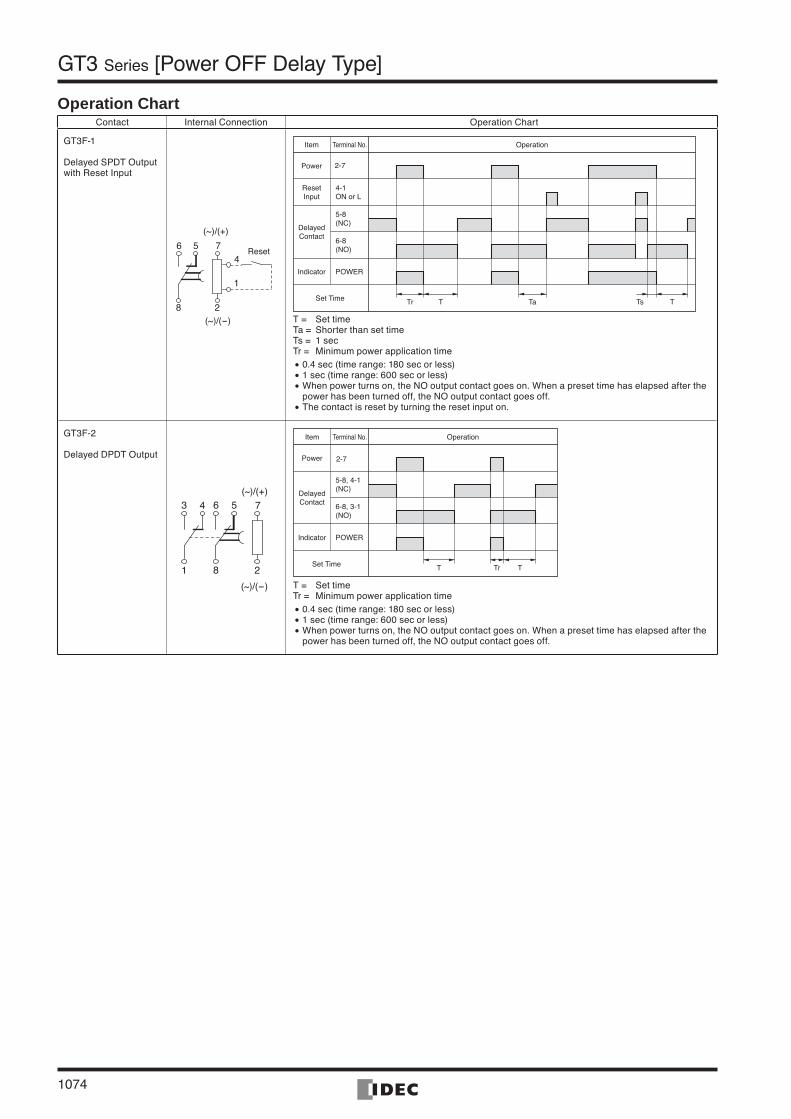
Operation ChartContact Internal Connection Operation Chart
GT3F-1
Delayed SPDT Output with Reset Input
475
1
2
6
8
Reset
(~)/(+)
(~)/(-)
Item Terminal No. Operation
Power 2-7
4-1 ON or L
ResetInput
5-8(NC)
6-8(NO)
POWER
DelayedContact
Indicator
Set Time Tr T Ta Ts T
T = Set timeTa = Shorter than set timeTs = 1 secTr = Minimum power application time
0.4 sec (time range: 180 sec or less) 1 sec (time range: 600 sec or less) When power turns on, the NO output contact goes on. When a preset time has elapsed after the power has been turned off, the NO output contact goes off. The contact is reset by turning the reset input on.
•••
•
GT3F-2
Delayed DPDT Output
73 4
1
5
2
6
8
(~)/(+)
(~)/(-)
Item Terminal No. Operation
Power 2-7
5-8, 4-1(NC)
6-8, 3-1(NO)
POWER
DelayedContact
Indicator
Set Time T TTr
T = Set timeTr = Minimum power application time
0.4 sec (time range: 180 sec or less) 1 sec (time range: 600 sec or less) When power turns on, the NO output contact goes on. When a preset time has elapsed after the power has been turned off, the NO output contact goes off.
•••
IDEC1066-1085.indd 1074IDEC1066-1085.indd 1074 07.8.17 4:10:07 PM07.8.17 4:10:07 PM
ControlUnits
Display Lights
DisplayUnits
SafetyProducts
TerminalBlocks
Comm.Terminals
AS-Interface
Relays & Timers
Sockets
Circuit Protectors
Power Supplies
PLCs & SmartRelay
Operator Interfaces
Sensors
Control Stations
Explosion Protection
References
FlushSilhouette
1075
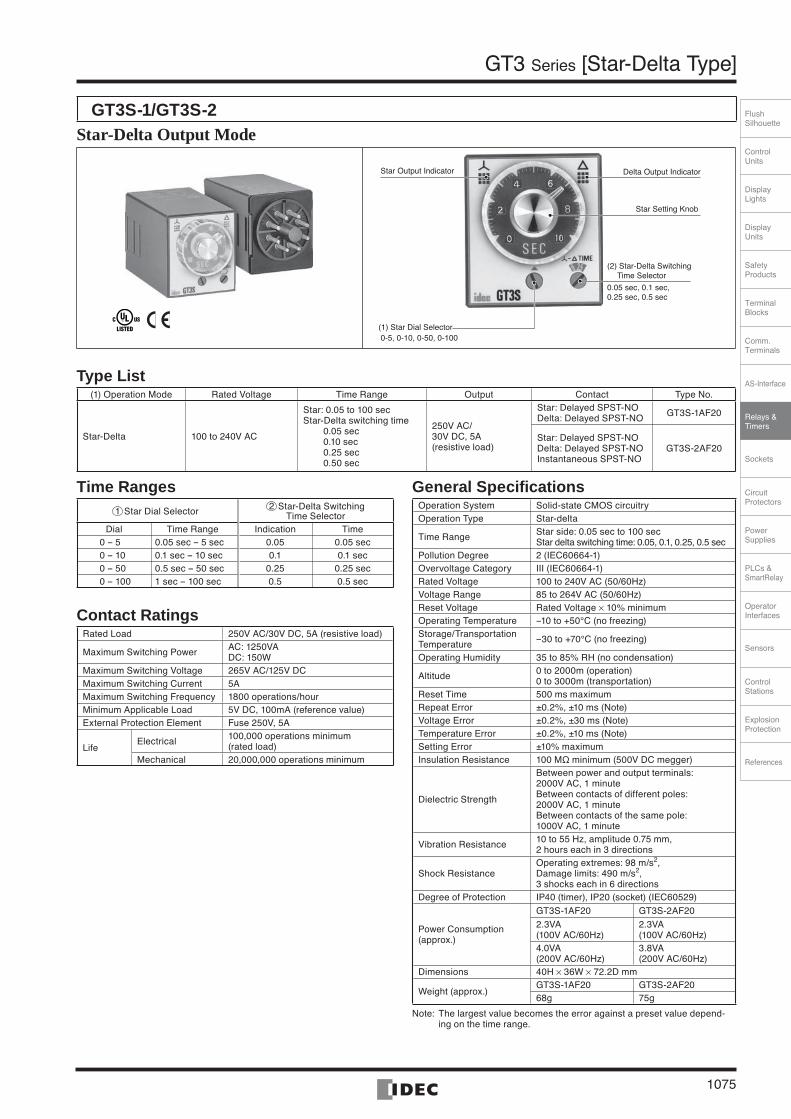
GT3 Series [Star-Delta Type]
GT3S-1/GT3S-2 Star-Delta Output Mode
Star Output Indicator Delta Output Indicator
Star Setting Knob
(2) Star-Delta Switching Time Selector
0.05 sec, 0.1 sec,0.25 sec, 0.5 sec
(1) Star Dial Selector 0-5, 0-10, 0-50, 0-100
Type List (1) Operation Mode Rated Voltage Time Range Output Contact Type No.
Star-Delta 100 to 240V AC
Star: 0.05 to 100 secStar-Delta switching time 0.05 sec 0.10 sec 0.25 sec 0.50 sec
250V AC/30V DC, 5A (resistive load)
Star: Delayed SPST-NODelta: Delayed SPST-NO GT3S-1AF20
Star: Delayed SPST-NODelta: Delayed SPST-NOInstantaneous SPST-NO
GT3S-2AF20
Time Ranges1 Star Dial Selector 2 Star-Delta Switching
Time SelectorDial Time Range Indication Time
0 -- 5 0.05 sec -- 5 sec 0.05 0.05 sec0 -- 10 0.1 sec -- 10 sec 0.1 0.1 sec0 -- 50 0.5 sec -- 50 sec 0.25 0.25 sec0 -- 100 1 sec -- 100 sec 0.5 0.5 sec
Contact RatingsRated Load 250V AC/30V DC, 5A (resistive load)
Maximum Switching Power AC: 1250VADC: 150W
Maximum Switching Voltage 265V AC/125V DCMaximum Switching Current 5AMaximum Switching Frequency 1800 operations/hourMinimum Applicable Load 5V DC, 100mA (reference value)External Protection Element Fuse 250V, 5A
LifeElectrical 100,000 operations minimum
(rated load)Mechanical 20,000,000 operations minimum
General SpecificationsOperation System Solid-state CMOS circuitry Operation Type Star-delta
Time Range Star side: 0.05 sec to 100 secStar delta switching time: 0.05, 0.1, 0.25, 0.5 sec
Pollution Degree 2 (IEC60664-1)Overvoltage Category III (IEC60664-1)Rated Voltage 100 to 240V AC (50/60Hz)Voltage Range 85 to 264V AC (50/60Hz)Reset Voltage Rated Voltage × 10% minimumOperating Temperature --10 to +50°C (no freezing) Storage/Transportation Temperature --30 to +70°C (no freezing)
Operating Humidity 35 to 85% RH (no condensation)
Altitude 0 to 2000m (operation) 0 to 3000m (transportation)
Reset Time 500 ms maximumRepeat Error ±0.2%, ±10 ms (Note) Voltage Error ±0.2%, ±30 ms (Note) Temperature Error ±0.2%, ±10 ms (Note) Setting Error ±10% maximumInsulation Resistance 100 MΩ minimum (500V DC megger)
Dielectric Strength
Between power and output terminals: 2000V AC, 1 minuteBetween contacts of different poles:2000V AC, 1 minuteBetween contacts of the same pole:1000V AC, 1 minute
Vibration Resistance 10 to 55 Hz, amplitude 0.75 mm, 2 hours each in 3 directions
Shock ResistanceOperating extremes: 98 m/s2,Damage limits: 490 m/s2,3 shocks each in 6 directions
Degree of Protection IP40 (timer), IP20 (socket) (IEC60529)
Power Consumption(approx.)
GT3S-1AF20 GT3S-2AF20
2.3VA (100V AC/60Hz)
2.3VA (100V AC/60Hz)
4.0VA (200V AC/60Hz)
3.8VA (200V AC/60Hz)
Dimensions 40H × 36W × 72.2D mm
Weight (approx.)GT3S-1AF20 GT3S-2AF2068g 75g
Note: The largest value becomes the error against a preset value depend-ing on the time range.
IDEC1066-1085.indd 1075IDEC1066-1085.indd 1075 07.8.17 4:10:07 PM07.8.17 4:10:07 PM
1076
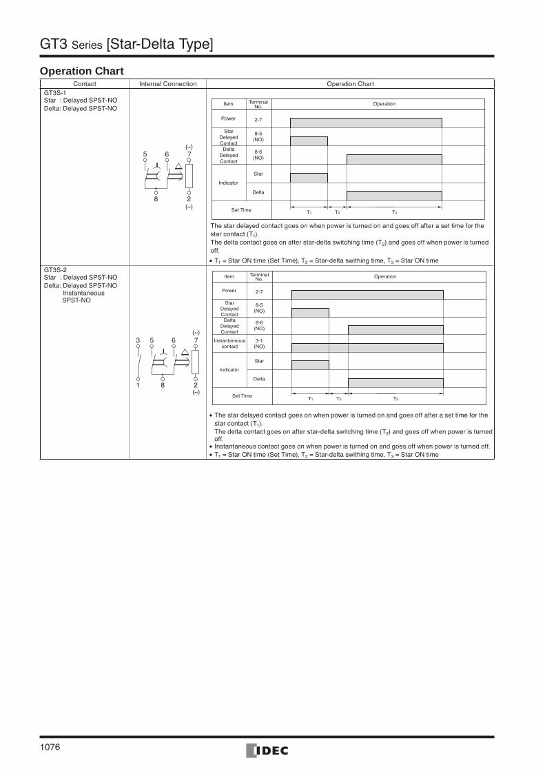
GT3 Series [Star-Delta Type]
Operation ChartContact Internal Connection Operation Chart
GT3S-1 Star : Delayed SPST-NODelta: Delayed SPST-NO
7
8 2
5 6(~)
(~)
The star delayed contact goes on when power is turned on and goes off after a set time for the star contact (T1). The delta contact goes on after star-delta switching time (T2) and goes off when power is turned off.
T1 = Star ON time (Set Time), T2 = Star-delta swithing time, T3 = Star ON time•GT3S-2 Star : Delayed SPST-NODelta: Delayed SPST-NO Instantaneous SPST-NO
7
8 2
5 63
1
(~)
(~)T1 T2 T3
3-1(NO)
8-5(NO)
8-6(NO)
Item TerminalNo. Operation
Power 2-7
Star
Delta
StarDelayedContactDelta
DelayedContact
Indicator
Instantaneouscontact
Set Time
The star delayed contact goes on when power is turned on and goes off after a set time for the star contact (T1). The delta contact goes on after star-delta switching time (T2) and goes off when power is turned off. Instantaneous contact goes on when power is turned on and goes off when power is turned off.T1 = Star ON time (Set Time), T2 = Star-delta swithing time, T3 = Star ON time
•
••
T1 T2 T3
8-5(NO)
8-6(NO)
Item TerminalNo. Operation
Power 2-7
Star
Delta
StarDelayedContactDelta
DelayedContact
Indicator
Set Time
IDEC1066-1085.indd 1076IDEC1066-1085.indd 1076 07.8.17 4:10:09 PM07.8.17 4:10:09 PM
ControlUnits
Display Lights
DisplayUnits
SafetyProducts
TerminalBlocks
Comm.Terminals
AS-Interface
Relays & Timers
Sockets
Circuit Protectors
Power Supplies
PLCs & SmartRelay
Operator Interfaces
Sensors
Control Stations
Explosion Protection
References
FlushSilhouette
1077
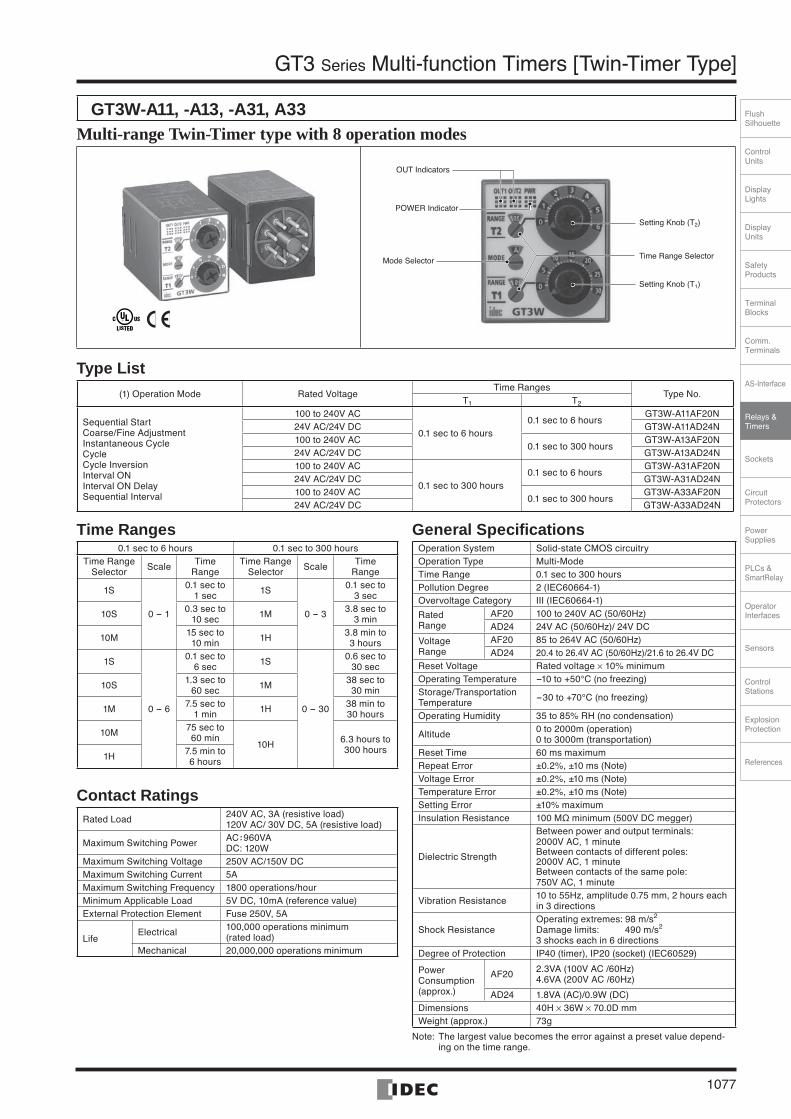
GT3 Series Multi-function Timers [Twin-Timer Type]
GT3W-A11, -A13, -A31, A33 Multi-range Twin-Timer type with 8 operation modes
OUT Indicators
Setting Knob (T2)
POWER Indicator
Mode SelectorTime Range Selector
Setting Knob (T1)
Type List (1) Operation Mode Rated Voltage
Time RangesType No.
T1 T2
Sequential StartCoarse/Fine AdjustmentInstantaneous CycleCycleCycle InversionInterval ONInterval ON DelaySequential Interval
100 to 240V AC
0.1 sec to 6 hours0.1 sec to 6 hours
GT3W-A11AF20N24V AC/24V DC GT3W-A11AD24N100 to 240V AC
0.1 sec to 300 hoursGT3W-A13AF20N
24V AC/24V DC GT3W-A13AD24N100 to 240V AC
0.1 sec to 300 hours0.1 sec to 6 hours
GT3W-A31AF20N24V AC/24V DC GT3W-A31AD24N100 to 240V AC
0.1 sec to 300 hoursGT3W-A33AF20N
24V AC/24V DC GT3W-A33AD24N
Time Ranges0.1 sec to 6 hours 0.1 sec to 300 hours
Time Range Selector Scale Time
RangeTime Range
Selector Scale TimeRange
1S
0 - 1
0.1 sec to 1 sec 1S
0 - 3
0.1 sec to 3 sec
10S 0.3 sec to 10 sec 1M 3.8 sec to
3 min
10M 15 sec to 10 min 1H 3.8 min to
3 hours
1S
0 - 6
0.1 sec to 6 sec 1S
0 - 30
0.6 sec to 30 sec
10S 1.3 sec to 60 sec 1M 38 sec to
30 min
1M 7.5 sec to 1 min 1H 38 min to
30 hours
10M 75 sec to 60 min
10H 6.3 hours to300 hours
1H 7.5 min to 6 hours
Contact RatingsRated Load 240V AC, 3A (resistive load)
120V AC/ 30V DC, 5A (resistive load)
Maximum Switching Power AC: 960VADC: 120W
Maximum Switching Voltage 250V AC/150V DCMaximum Switching Current 5AMaximum Switching Frequency 1800 operations/hourMinimum Applicable Load 5V DC, 10mA (reference value)External Protection Element Fuse 250V, 5A
LifeElectrical 100,000 operations minimum
(rated load)Mechanical 20,000,000 operations minimum
General SpecificationsOperation System Solid-state CMOS circuitry Operation Type Multi-ModeTime Range 0.1 sec to 300 hoursPollution Degree 2 (IEC60664-1)Overvoltage Category III (IEC60664-1)
Rated Range
AF20 100 to 240V AC (50/60Hz)AD24 24V AC (50/60Hz)/ 24V DC
Voltage Range
AF20 85 to 264V AC (50/60Hz)AD24 20.4 to 26.4V AC (50/60Hz)/21.6 to 26.4V DC
Reset Voltage Rated voltage × 10% minimumOperating Temperature -10 to +50°C (no freezing) Storage/Transportation Temperature -30 to +70°C (no freezing)
Operating Humidity 35 to 85% RH (no condensation)
Altitude 0 to 2000m (operation) 0 to 3000m (transportation)
Reset Time 60 ms maximumRepeat Error ±0.2%, ±10 ms (Note) Voltage Error ±0.2%, ±10 ms (Note) Temperature Error ±0.2%, ±10 ms (Note) Setting Error ±10% maximumInsulation Resistance 100 MΩ minimum (500V DC megger)
Dielectric Strength
Between power and output terminals:2000V AC, 1 minuteBetween contacts of different poles:2000V AC, 1 minuteBetween contacts of the same pole:750V AC, 1 minute
Vibration Resistance 10 to 55Hz, amplitude 0.75 mm, 2 hours each in 3 directions
Shock ResistanceOperating extremes: 98 m/s2 Damage limits: 490 m/s2 3 shocks each in 6 directions
Degree of Protection IP40 (timer), IP20 (socket) (IEC60529)
Power Consumption (approx.)
AF20 2.3VA (100V AC /60Hz)4.6VA (200V AC /60Hz)
AD24 1.8VA (AC)/0.9W (DC)Dimensions 40H × 36W × 70.0D mmWeight (approx.) 73g
Note: The largest value becomes the error against a preset value depend-ing on the time range.
IDEC1066-1085.indd 1077IDEC1066-1085.indd 1077 07.8.17 4:10:09 PM07.8.17 4:10:09 PM
1078
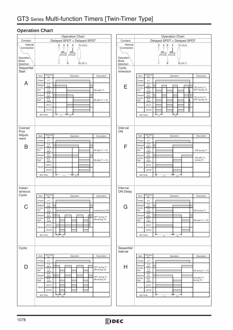
GT3 Series Multi-function Timers [Twin-Timer Type]
Operation ChartContact Delayed SPDT + Delayed SPDT
7(~)/(+)
2(~)/(-)
3 4
1
56
8
SequentialStart
A
T1
DelayedContactRy2
Operation
Indicator
TerminalNo.Item
Power
DelayedContactRy1
5-8(NC) 6-8(NO)
2-7
1-4(NC)
OUT1
1-3(NO)
OUT2
Set Time
Description
ON after T1
T2
ON after T1 + T2
Coarse/Fine Adjust-ment
B
T1 T2
DelayedContactRy2
Operation
Indicator
TerminalNo.Item
Power
DelayedContactRy1
5-8(NC) 6-8(NO)
2-7
1-4(NC)
OUT1
1-3(NO)
OUT2
Set Time
Description
ON after T1 + T2
ON after T1 + T2
Instan-taneous Cycle
C
T1 T2
DelayedContactRy2
Operation
Indicator
TerminalNo.Item
Power
DelayedContactRy1
5-8(NC) 6-8(NO)
2-7
1-4(NC)
OUT1
1-3(NO)
OUT2
Set Time
Description
Instantaneous ON
OFF during T1ON during T2
Cycle
D
T1 T2
DelayedContactRy2
Operation
Indicator
TerminalNo.Item
Power
DelayedContactRy1
5-8(NC) 6-8(NO)
2-7
1-4(NC)
OUT1
1-3(NO)
OUT2
Set Time
Description
OFF during T1ON during T2
OFF during T1ON during T2
Operation ChartContact Delayed SPDT + Delayed SPDT
7(~)/(+)
2(~)/(-)
3 4
1
56
8
Cycle Inversion
E
T1 T2
DelayedContactRy2
Operation
Indicator
TerminalNo.Item
Power
DelayedContactRy1
5-8(NC) 6-8(NO)
2-7
1-4(NC)
OUT1
1-3(NO)
OUT2
Set Time
Description
ON during T1OFF during T2
ON during T1OFF during T2
Interval ON
F
T1 T2
DelayedContactRy2
Operation
Indicator
TerminalNo.Item
Power
DelayedContactRy1
5-8(NC) 6-8(NO)
2-7
1-4(NC)
OUT1
1-3(NO)
OUT2
Set Time
Description
ON during T1
ON after T1,during T2
Interval ON Delay
G
T1 T2
DelayedContactRy2
Operation
Indicator
TerminalNo.Item
Power
DelayedContactRy1
5-8(NC) 6-8(NO)
2-7
1-4(NC)
OUT1
1-3(NO)
OUT2
Set Time
Description
ON during T1
ON after T1 + T2
Sequential Interval
H
T1 T2
DelayedContactRy2
Operation
Indicator
TerminalNo.Item
Power
DelayedContactRy1
5-8(NC) 6-8(NO)
2-7
1-4(NC)
OUT1
1-3(NO)
OUT2
Set Time
Description
ON during T1 + T2
ON after T1,during T2
Operation Chart
Operation ModeSelection
InternalConnection
Operation ModeSelection
InternalConnection
IDEC1066-1085.indd 1078IDEC1066-1085.indd 1078 07.8.17 4:10:11 PM07.8.17 4:10:11 PM

ControlUnits
Display Lights
DisplayUnits
SafetyProducts
TerminalBlocks
Comm.Terminals
AS-Interface
Relays & Timers
Sockets
Circuit Protectors
Power Supplies
PLCs & SmartRelay
Operator Interfaces
Sensors
Control Stations
Explosion Protection
References
FlushSilhouette
1079
GT3 Series Multi-function Timers [Accessories]
Applicable Sockets & Hold-Down Springs (Optional)DIN Rail Mount Socket
Item Type No. Ordering Type No. Package Quantity Remarks
Socket
8-Pin Screw TerminalSR2P-05A SR2P-05A 1SR2P-06A SR2P-06A 1SR2P-05C SR2P-05C 1 Finger-safe type
11-Pin Screw TerminalSR3P-05A SR3P-05A 1SR3P-06A SR3P-06A 1SR3P-05C SR3P-05C 1 Finger-safe type
Hold-Down SpringSFA-202 SFA-202PN20 10 sets (20 pcs) For SR2P-06A/SR3P-06A
(2 pcs/set)
SFA-203 SFA-203PN20 10 sets (20 pcs) For SR3P-05A(2 pcs/set)
Note: All are UL recognized, CSA certified, and TÜV approved.
SR2P-06A SR3P-05A SR3P-06A SFA-202 (2 pcs/set) SFA-203 (2 pcs/set)
Panel Mount SocketItem Type No. Ordering Type No. Package Quantity Remarks
Socket8-Pin Solder Terminal SR2P-511 SR2P-511 1
11-Pin Solder Terminal SR3P-511 SR3P-511 1
Hold-Down Spring SFA-402 SFA-402PN10 10 For SR2P-511/SR3P-511
Note: SR2P-511 and SR3P-511 are UL recognized and CSA certified.
SR2P-511 SR3P-511 SFA-402
Panel Mount Adapter and wiring Socket Adapter Package Quantity: 1
Item Type No.
DIN 48mm Square Panel Mount Adapter
Color: Gray RTB-G01
Color: Beige RTB-M01
Color: Black RTB-B01
WiringSocketAdapter
8-Pin Solder Terminal SR6P-S08 8-Pin Screw Terminal SR6P-M08G 11-Pin Solder Terminal SR6P-S1111-Pin Screw Terminal SR6P-M11G
Finger-safe 11-pin screw wiring socket adapter (Type No.: SR6P-C11) is also available.
•
•
•
•
Installation of Hold-Down Springs(DIN Rail Mount Socket) (Panel Mount Socket)
SocketSR2P-06A
Hold-Down Spring (optional)SFA-202 (2 pcs/set)
Insert the springs into the outer slots with the projections facing inside.
SocketSR3P-05A
Insert the springs into the slots.
Hold-Down Spring (optional)SFA-203 (2 pcs/set)
8-Pin SocketSR2P-511SR2P-70
Hold-Down SpringSFA-402
Insert
Note: Once installed into the socket, the hold-down springs cannot be removed.
•
(8-pin Wiring Socket Adapter)
(11-pin Wiring Socket Adapter)
SR6P-S08 SR6P-S11
(8-pin Screw Wiring Socket Adapter)
(11-pin Screw Wiring Socket Adapter)
SR6P-M08G SR6P-M11G
IDEC1066-1085.indd 1079IDEC1066-1085.indd 1079 07.8.17 4:10:12 PM07.8.17 4:10:12 PM
1080
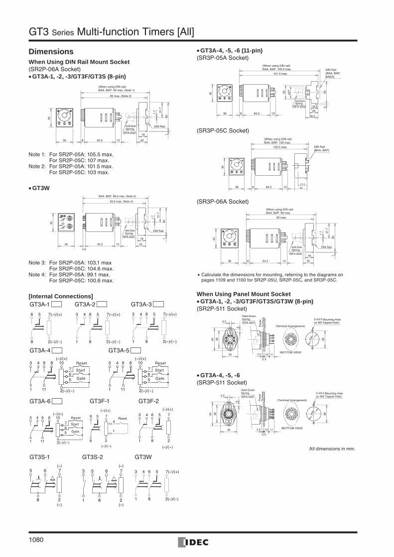
GT3 Series Multi-function Timers [All]
DimensionsWhen Using DIN Rail Mount Socket(SR2P-06A Socket)
GT3A-1, -2, -3/GT3F/GT3S (8-pin)
(When using DIN rail)BAA, BAP: 99 max. (Note 1)
(SFA-202)
DIN RailHold-DownSpring
1.7 31
.7
601
95 max. (Note 2)
40
36
18
228 64.2 13
Note 1: For SR2P-05A: 105.5 max. For SR2P-05C: 107 max.Note 2: For SR2P-05A: 101.5 max. For SR2P-05C: 103 max.
GT3W( g )BAA, BAP: 96.6 max. (Note 3)
(SFA-202)
DIN Rail
1.7 31
.7
601
92.6 max. (Note 4)
40
36
18
22
5.6
64.2 13
Hold-DownSpring
Note 3: For SR2P-05A: 103.1 max For SR2P-05C: 104.6 max.Note 4: For SR2P-05A: 99.1 max. For SR2P-05C: 100.6 max.
[Internal Connections]GT3A-1 GT3A-2 GT3A-3
7(~)/(+)
2(~)/(-)
56
8
7(~)/(+)
2(~)/(-)
3 4
1
56
8
7(~)/(+)
2(~)/(-)
3 4
1
56
8
GT3A-4 GT3A-5
7103 4
1
8
5
2(~)/(-)
6
9
11
Gate
Start
Reset(~)/(+)
7103 4
1
8
5
2(~)/(-)
6
9
11
Gate
Start
Reset(~)/(+)
GT3A-6 GT3F-1 GT3F-2
7103 4
1
8
5
2(~)/(-)
6
9
11
Gate
Start
Reset(~)/(+)
475
1
2
6
8
Reset
(~)/(+)
(~)/(-)
73 4
1
5
2
6
8
(~)/(+)
(~)/(-)
GT3S-1 GT3S-2 GT3W
7
8 2
5 6(~)
(~)
7
8 2
5 63
1
(~)
(~)
7(~)/(+)
2(~)/(-)
3 4
1
56
8
•
•
GT3A-4, -5, -6 (11-pin)(SR3P-05A Socket)
(When using DIN rail)BAA, BAP: 105.5 max.
(SFA-203)
DIN Rail(BAA, BAP, BADA)
101.5 max.
40
36 8 64.2 13
16.5
20
28.5
ø2733 52
3
Hold-DownSpring
(SR3P-05C Socket)(When using DIN rail)BAA, BAP: 105 max.
103.5 max.
40
36 8 64.2 30
21.513
DIN Rail(BAA, BAP)
(SR3P-06A Socket)(When using DIN rail)BAA, BAP: 99 max.
(SFA-202)
DIN Rail
1.7 31
.7
601
95 max.
40
36
18
228 64.2 13
Hold-DownSpring
Calculate the dimensions for mounting, referring to the diagrams on pages 1109 and 1100 for SR2P-05U, SR2P-05C, and SR3P-05C.
When Using Panel Mount SocketGT3A-1, -2, -3/GT3F/GT3S/GT3W (8-pin)
(SR2P-511 Socket)
(Terminal Arrangement)
(BOTTOM VIEW)
Pan
elS
urfa
ce
2.5
(SFA-402)2-ø3.5 Mounting Hole(or M3 Tapped Hole)
123
4 567
8
6
3850
4.2
34 2.5 10 11
ø30
38
Hold-DownSpring
GT3A-4, -5, -6 (SR3P-511 Socket)
2.5
(SFA-402)
6
3850
4.2
34 2.5 10 11
ø30
38
12
34
5 6 789
1110
(Terminal Arrangement)
(BOTTOM VIEW)
Pan
elS
urfa
ce 2-ø3.5 Mounting Hole(or M3 Tapped Hole)
Hold-DownSpring
All dimensions in mm.
•
•
•
•
IDEC1066-1085.indd 1080IDEC1066-1085.indd 1080 07.8.17 4:10:13 PM07.8.17 4:10:13 PM
ControlUnits
Display Lights
DisplayUnits
SafetyProducts
TerminalBlocks
Comm.Terminals
AS-Interface
Relays & Timers
Sockets
Circuit Protectors
Power Supplies
PLCs & SmartRelay
Operator Interfaces
Sensors
Control Stations
Explosion Protection
References
FlushSilhouette
1081
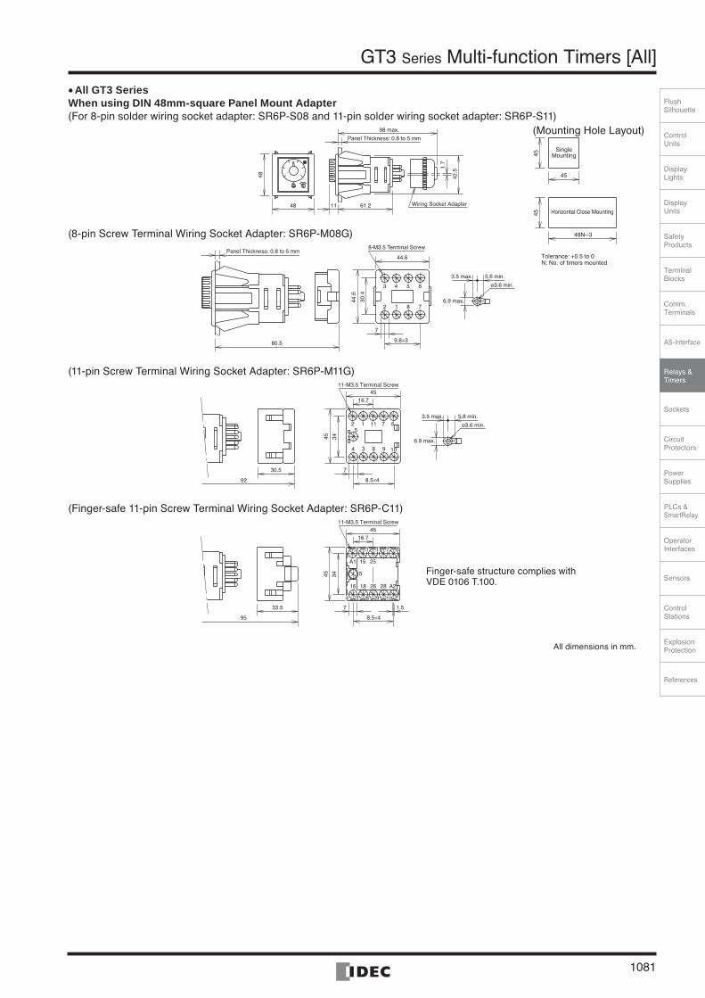
GT3 Series Multi-function Timers [All]
All GT3 Series When using DIN 48mm-square Panel Mount Adapter(For 8-pin solder wiring socket adapter: SR6P-S08 and 11-pin solder wiring socket adapter: SR6P-S11)
Wiring Socket Adapter
1.7
48
48
11 61.2
Panel Thickness: 0.8 to 5 mm
42.5
98 max.
(8-pin Screw Terminal Wiring Socket Adapter: SR6P-M08G)
ø3.6 min.
8-M3.5 Terminal Screw
2 1 8 7
3 4 5 6
6.9 max.30.4
44.6
Panel Thickness: 0.8 to 5 mm
80.5
7
9.8×3
44.6
3.5 max. 5.6 min.
(11-pin Screw Terminal Wiring Socket Adapter: SR6P-M11G)
ø3.6 min.
6.9 max.
92
4 3 8 9 10
2 115
1 7 63.5 max. 5.8 min.
30.5 7
8.5×4
16.745
3445
11-M3.5 Terminal Screw
(Finger-safe 11-pin Screw Terminal Wiring Socket Adapter: SR6P-C11)
95
5
A2
15A1
16 18 26 28
7
8.5×4
16.745
3445
1.533.5
25
2 1 11 7 6
4 3 8 9 10
11-M3.5 Terminal Screw
All dimensions in mm.
•
(Mounting Hole Layout)
Horizontal Close Mounting
SingleMounting
45
4545
48N--3
Tolerance: +0.5 to 0N: No. of timers mounted
Finger-safe structure complies with VDE 0106 T.100.
IDEC1066-1085.indd 1081IDEC1066-1085.indd 1081 07.8.17 4:10:15 PM07.8.17 4:10:15 PM
1082
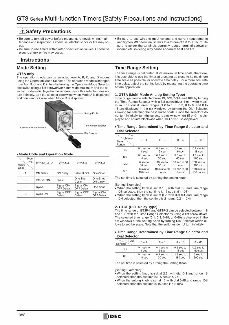
GT3 Series Multi-function Timers [Safety Precautions and Instructions]
! Safety Precautions
Instructions
Be sure to turn off power before mounting, removal, wiring, main-tenance and inspection. Otherwise, electric shock or fire may oc-cur.Be sure to use timers within rated specification values. Otherwise electric shock or fire may occur.
•
•
Be sure to use wires to meet voltage and current requirements and tighten M3.5 terminal screws to a torque of 1.0 to 1.3 N•m. Be sure to solder the terminals correctly. Loose terminal screws or incomplete soldering may cause abnormal heat and fire.
•
Mode SettingGT3A onlyThe operation mode can be selected from A, B, C, and D modes using the Operation Mode Selector. The operation mode is changed from A to B, C, and D in turn by turning the Operation Mode Selector clockwise using a flat screwdriver 4 mm wide maximum and the se-lected mode is displayed in the window. Since this selector does not turn infinitely, turn the selector clockwise when Mode A is displayed and counterclockwise when Mode D is displayed.
Setting Knob
Time Range SelectorOperation Mode Selector
Dial Selector
Mode Code and Operation ModeType
No.MODECode
GT3A-1, -2, -3 GT3A-4 GT3A-5 GT3A-6
A ON Delay ON Delay Interval ON One-Shot
B Interval ON Cycle One Shot Cycle
One-Shot ON Delay
C Cycle Signal ON/OFF Delay
Signal ON/OFF Delay One-Shot
D Cycle ON Signal OFF Delay
Signal OFF Delay
Signal ON/OFF Delay
•
Time Range Setting The time range is calibrated at its maximum time scale, therefore, it is desirable to use the timer at a setting as close to its maximum time scale as possible for accurate time delay. For a more accurate time delay, adjust the setting knob by measuring the operating time before application.
1. GT3A (Multi-Mode Analog Setting Type) Time range can be selected from 1S, 10S, 10M, and 10H by turning the Time Range Selector with a flat screwdriver 4 mm wide maxi-mum. The four different ranges of 0 to 1, 0 to 3, 0 to 6, and 0 to 18 are displayed in the six windows by turning the Dial Selector, allowing for selecting the best suited scale. Since the selectors do not turn infinitely, turn the selectors clockwise when 1S or 0-1 is dis-played and counterclockwise when 10H or 0-18 is displayed.
Time Range Determined by Time Range Selector and Dial Selector
DialSelector
TimeRange
0 - 1 0 - 3 0 - 6 0 - 18
1S 0.1 sec to 1 sec
0.1 sec to 3 sec
0.1 sec to 6 sec
0.2 sec to 18 sec
10S 0.1 sec to 10 sec
0.3 sec to 30 sec
0.6 sec to 60 sec
1.8 sec to 180 sec
10M 6 sec to 10 min
18 sec to 30 min
36 sec to 60 min
108 sec to 180 min
10H 6 min to 10 hours
18 min to 30 hours
36 min to 60 hours
108 min to 180 hours
The set time is selected by turning the setting knob.
[Setting Examples]When the setting knob is set at 1.5, with dial 0-3 and time range 10S selected, then the set time is 15 sec (1.5 × 10S).When the setting knob is set at 0.2, with dial 0-1 and time range 10H selected, then the set time is 2 hours (0.2 × 10H).
2. GT3F (OFF Delay Type)The time range of GT3F-1 and GT3F-2 can be selected between 1S and 10S with the Time Range Selector by using a flat screw driver. The selected time range (0-1, 0-3, 0-18, or 0-60) is displayed in the six windows of the Setting Knob by turning Dial Selector which al-lows to set the scale. Note that the switches do not turn infinitely.
Time Range Determined by Time Range Selector and Dial Selector
(1) Dial(2) Range 0 - 1 0 - 3 0 - 18 0 - 60
1S 0.1 sec to 1 sec
0.1 sec to 3 sec
0.2 sec to 18 sec
0.6 sec to 60 sec
10S 0.1 sec to 10 sec
0.3 sec to 30 sec
1.8 sec to 180 sec
6 sec to 600 sec
The set time is selected by turning the Setting Knob.
[Setting Examples]When the setting knob is set at 2.5, with dial 0-3 and range 1S selected, then the set time is 2.5 sec (2.5 × 1S). When the setting knob is set at 15, with dial 0-18 and range 10S selected, then the set time is 150 sec (15 × 10S).
•
•
•
•
•
•
IDEC1066-1085.indd 1082IDEC1066-1085.indd 1082 07.8.17 4:10:16 PM07.8.17 4:10:16 PM
ControlUnits
Display Lights
DisplayUnits
SafetyProducts
TerminalBlocks
Comm.Terminals
AS-Interface
Relays & Timers
Sockets
Circuit Protectors
Power Supplies
PLCs & SmartRelay
Operator Interfaces
Sensors
Control Stations
Explosion Protection
References
FlushSilhouette
1083
GT3 Series Multi-function Timers [Instructions]
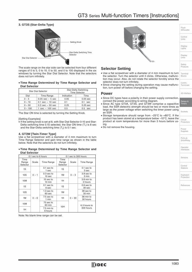
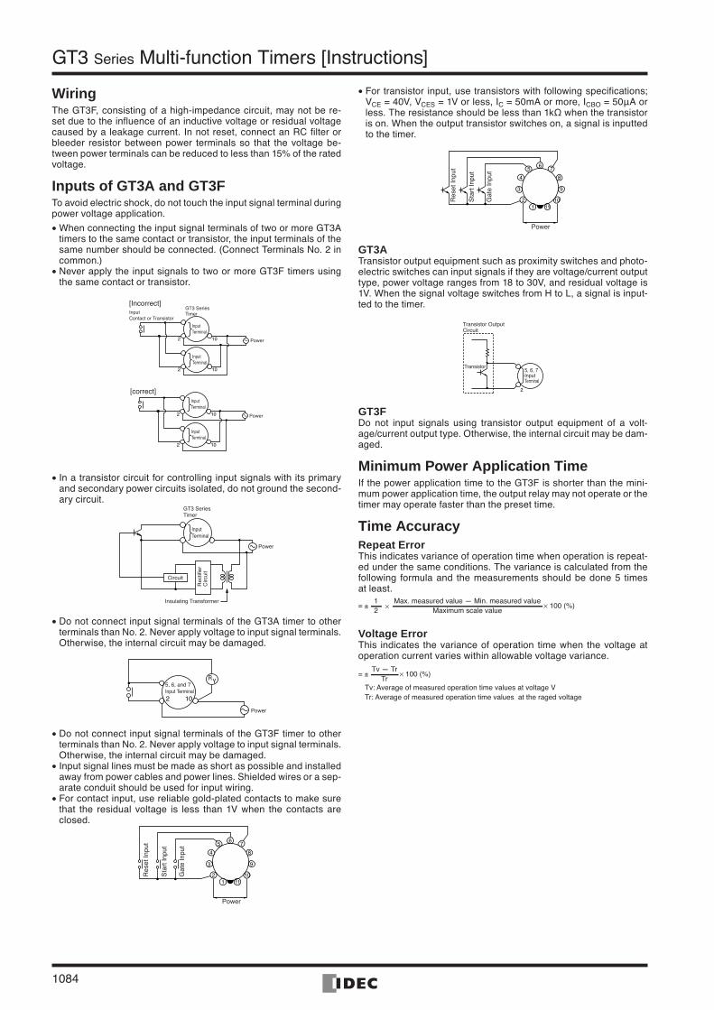
3. GT3S (Star-Delta Type)
Setting Knob
Star-Delta Switching Time Selector
Star Dial Selector
The scale range on the star side can be selected from four different ranges of 0 to 5, 0 to 10, 0 to 50, and 0 to 100 displayed in the six windows by turning the Star Dial Selector. Note that the selectors does not turn infinitely.
Time Range Determined by Time Range Selector and Dial Selector
Star Dial Selector Star-Delta Switching Time Selector
Dial Time Range Indication Time0 -- 5 0.05 sec -- 5 sec 0.05 0.05 sec0 -- 10 0.1 sec -- 10 sec 0.1 0.1 sec0 -- 50 0.3 sec -- 50 sec 0.25 0.25 sec0 -- 100 1 sec -- 100 sec 0.5 0.5 sec
The Star ON time is selected by turning the Setting Knob.
[Setting Examples]If the setting knob is set at 8, with Star Dial Selector 0-10 and Star- Delta switching time 0.1S selected, the Star ON time (T1) is 8 sec and the Star-Delta switching time (T2) is 0.1 sec.
4. GT3W [Twin-Timer Type]Use a flat screwdriver with a diameter of 4 mm maximum to turn Time Range Selector and gain time range as shown in the table below. Note that the selectors do not turn infinitely.
Time Range Determined by Time Range Selector and Dial Selector
0.1 sec to 6 hours 0.1 sec to 300 hoursTime
Range Selector
Scale Time RangeTime
Range Selector
Scale Time Range
1S
0 - 1
0.1 sec to1 sec 1S
0 - 3
0.1 sec to3 sec
10S 0.3 sec to10 sec 1M 3.8 sec to
3 min
10M 15 sec to10 min 1H 3.8 min to
3 hours
1S
0 - 6
0.1 sec to6 sec 1S
0 - 30
0.6 sec to30 sec
10S 1.3 sec to60 sec 1M 38 sec to
30 min
1M 7.5 sec to1 min 1H 38 min to
30 hours
10M 75 sec to60 min
10H 6.3 hours to300 hours
1H 7.5 min to6 hours
Note: No blank time range can be set.
•
•
•
Selector Setting Use a flat screwdriver with a diameter of 4 mm maximum to turn the selector. Turn the selector until it clicks. Otherwise, malfunc-tion may occur. Also, do not rotate the selector forcibly since the selector does not turn infinitely. Since changing the setting during operation may cause malfunc-tion, turn power off before changing the setting.
PowerSince DC types have a polarity in their power supply connection, connect the power according to wiring diagram. Since AC type GT3A, GT3S, and GT3W comprise a capacitive load, the SSR dielectric strength should be two or more times as large as the power voltage when switching the timer power using an SSR. Storage temperature should range from -25°C to +80°C. If the product has been stored at a temperature below -10°C, leave the product at room temperatures for more than 3 hours before us-ing.Do not remove the housing.
•
•
•
•
•
•
IDEC1066-1085.indd 1083IDEC1066-1085.indd 1083 07.8.17 4:10:17 PM07.8.17 4:10:17 PM
1084
GT3 Series Multi-function Timers [Instructions]
WiringThe GT3F, consisting of a high-impedance circuit, may not be re-set due to the influence of an inductive voltage or residual voltage caused by a leakage current. In not reset, connect an RC filter or bleeder resistor between power terminals so that the voltage be-tween power terminals can be reduced to less than 15% of the rated voltage.
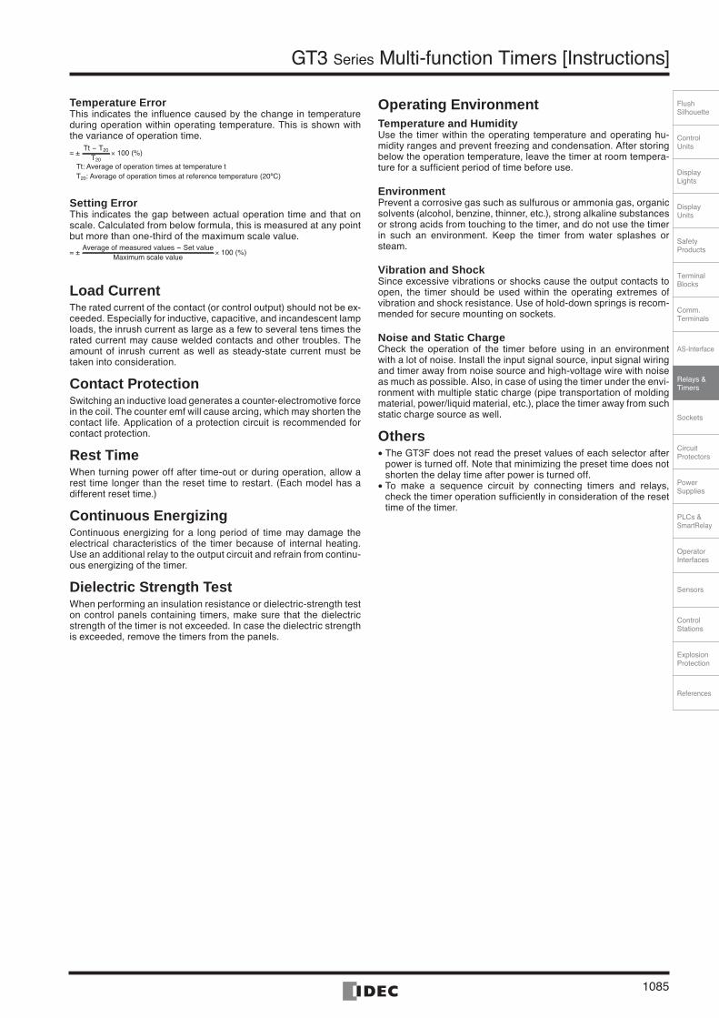
Inputs of GT3A and GT3F To avoid electric shock, do not touch the input signal terminal during power voltage application.
When connecting the input signal terminals of two or more GT3A timers to the same contact or transistor, the input terminals of the same number should be connected. (Connect Terminals No. 2 in common.)Never apply the input signals to two or more GT3F timers using the same contact or transistor.
Input Contact or Transistor
GT3 SeriesTimer
InputTerminal
InputTerminal
Power10
10
2
2
[Incorrect]
Power10
10
2
2
InputTerminal
InputTerminal
[correct]
In a transistor circuit for controlling input signals with its primary and secondary power circuits isolated, do not ground the second-ary circuit.
GT3 SeriesTimer
InputTerminal
Power
Rec
tifie
r C
ircui
t
Circuit
Insulating Transformer
Do not connect input signal terminals of the GT3A timer to other terminals than No. 2. Never apply voltage to input signal terminals. Otherwise, the internal circuit may be damaged.
Power
RY5, 6, and 7Input Terminal2 10
Do not connect input signal terminals of the GT3F timer to other terminals than No. 2. Never apply voltage to input signal terminals. Otherwise, the internal circuit may be damaged. Input signal lines must be made as short as possible and installed away from power cables and power lines. Shielded wires or a sep-arate conduit should be used for input wiring. For contact input, use reliable gold-plated contacts to make sure that the residual voltage is less than 1V when the contacts are closed.
65
4
3
21 11
10
9
8
7
Power
Res
et In
put
Sta
rt In
put
Gat
e In
put
•
•
•
•
•
•
•
For transistor input, use transistors with following specifications; VCE = 40V, VCES = 1V or less, IC = 50mA or more, ICBO = 50μA or less. The resistance should be less than 1kΩ when the transistor is on. When the output transistor switches on, a signal is inputted to the timer.
65
4
3
21 11
10
9
8
7
Power
Res
et In
put
Sta
rt In
put
Gat
e In
put
GT3ATransistor output equipment such as proximity switches and photo-electric switches can input signals if they are voltage/current output type, power voltage ranges from 18 to 30V, and residual voltage is 1V. When the signal voltage switches from H to L, a signal is input-ted to the timer.
Transistor
Transistor OutputCircuit
2
5, 6, 7InputTerminal
GT3F Do not input signals using transistor output equipment of a volt-age/current output type. Otherwise, the internal circuit may be dam-aged.
Minimum Power Application TimeIf the power application time to the GT3F is shorter than the mini-mum power application time, the output relay may not operate or the timer may operate faster than the preset time.
Time AccuracyRepeat ErrorThis indicates variance of operation time when operation is repeat-ed under the same conditions. The variance is calculated from the following formula and the measurements should be done 5 times at least.
Max. measured value - Min. measured valueMaximum scale value
12
= ± × × 100 (%)
Voltage ErrorThis indicates the variance of operation time when the voltage at operation current varies within allowable voltage variance.
Tv - TrTr
= ± × 100 (%)
Tv: Average of measured operation time values at voltage V Tr: Average of measured operation time values at the raged voltage
•
IDEC1066-1085.indd 1084IDEC1066-1085.indd 1084 07.8.17 4:10:18 PM07.8.17 4:10:18 PM
ControlUnits
Display Lights
DisplayUnits
SafetyProducts
TerminalBlocks
Comm.Terminals
AS-Interface
Relays & Timers
Sockets
Circuit Protectors
Power Supplies
PLCs & SmartRelay
Operator Interfaces
Sensors
Control Stations
Explosion Protection
References
FlushSilhouette
1085
GT3 Series Multi-function Timers [Instructions]
Temperature ErrorThis indicates the influence caused by the change in temperature during operation within operating temperature. This is shown with the variance of operation time.
Tt - T20
T20= ± × 100 (%)
Tt: Average of operation times at temperature t T20: Average of operation times at reference temperature (20ºC)
Setting ErrorThis indicates the gap between actual operation time and that on scale. Calculated from below formula, this is measured at any point but more than one-third of the maximum scale value.
Average of measured values - Set valueMaximum scale value
= ± × 100 (%)
Load CurrentThe rated current of the contact (or control output) should not be ex-ceeded. Especially for inductive, capacitive, and incandescent lamp loads, the inrush current as large as a few to several tens times the rated current may cause welded contacts and other troubles. The amount of inrush current as well as steady-state current must be taken into consideration.
Contact ProtectionSwitching an inductive load generates a counter-electromotive force in the coil. The counter emf will cause arcing, which may shorten the contact life. Application of a protection circuit is recommended for contact protection.
Rest TimeWhen turning power off after time-out or during operation, allow a rest time longer than the reset time to restart. (Each model has a different reset time.)
Continuous EnergizingContinuous energizing for a long period of time may damage the electrical characteristics of the timer because of internal heating. Use an additional relay to the output circuit and refrain from continu-ous energizing of the timer.
Dielectric Strength TestWhen performing an insulation resistance or dielectric-strength test on control panels containing timers, make sure that the dielectric strength of the timer is not exceeded. In case the dielectric strength is exceeded, remove the timers from the panels.
Operating EnvironmentTemperature and Humidity Use the timer within the operating temperature and operating hu-midity ranges and prevent freezing and condensation. After storing below the operation temperature, leave the timer at room tempera-ture for a sufficient period of time before use.
EnvironmentPrevent a corrosive gas such as sulfurous or ammonia gas, organic solvents (alcohol, benzine, thinner, etc.), strong alkaline substances or strong acids from touching to the timer, and do not use the timer in such an environment. Keep the timer from water splashes or steam.
Vibration and Shock Since excessive vibrations or shocks cause the output contacts to open, the timer should be used within the operating extremes of vibration and shock resistance. Use of hold-down springs is recom-mended for secure mounting on sockets.
Noise and Static Charge Check the operation of the timer before using in an environment with a lot of noise. Install the input signal source, input signal wiring and timer away from noise source and high-voltage wire with noise as much as possible. Also, in case of using the timer under the envi-ronment with multiple static charge (pipe transportation of molding material, power/liquid material, etc.), place the timer away from such static charge source as well.
OthersThe GT3F does not read the preset values of each selector after power is turned off. Note that minimizing the preset time does not shorten the delay time after power is turned off. To make a sequence circuit by connecting timers and relays, check the timer operation sufficiently in consideration of the reset time of the timer.
•
•
IDEC1066-1085.indd 1085IDEC1066-1085.indd 1085 07.8.17 4:10:19 PM07.8.17 4:10:19 PM