Embed Size (px)
Citation preview
Subject to change – O.Gerlach, T. Lechner, K.Schiffner 09.2008 - 1MA119_2e
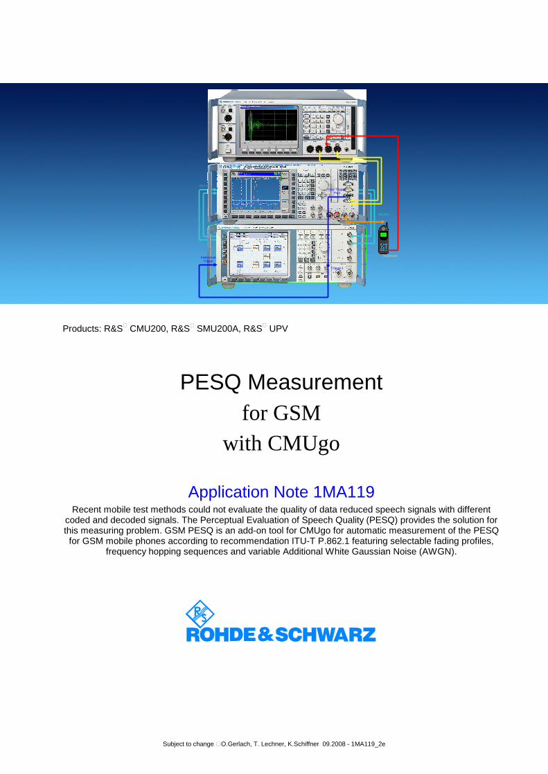
Products: R&S® CMU200, R&S® SMU200A, R&S® UPV
PESQ Measurement for GSM
with CMUgo
Application Note 1MA119 Recent mobile test methods could not evaluate the quality of data reduced speech signals with different
coded and decoded signals. The Perceptual Evaluation of Speech Quality (PESQ) provides the solution for this measuring problem. GSM PESQ is an add-on tool for CMUgo for automatic measurement of the PESQ for GSM mobile phones according to recommendation ITU-T P.862.1 featuring selectable fading profiles,
frequency hopping sequences and variable Additional White Gaussian Noise (AWGN).
Hop Trigger Pin4
Trigger 1
Instrument Trigger
Earphone
I/Q Out
I/Q In
GSM PESQ Measurement for CMUgo
1MA119 2 Rohde & Schwarz
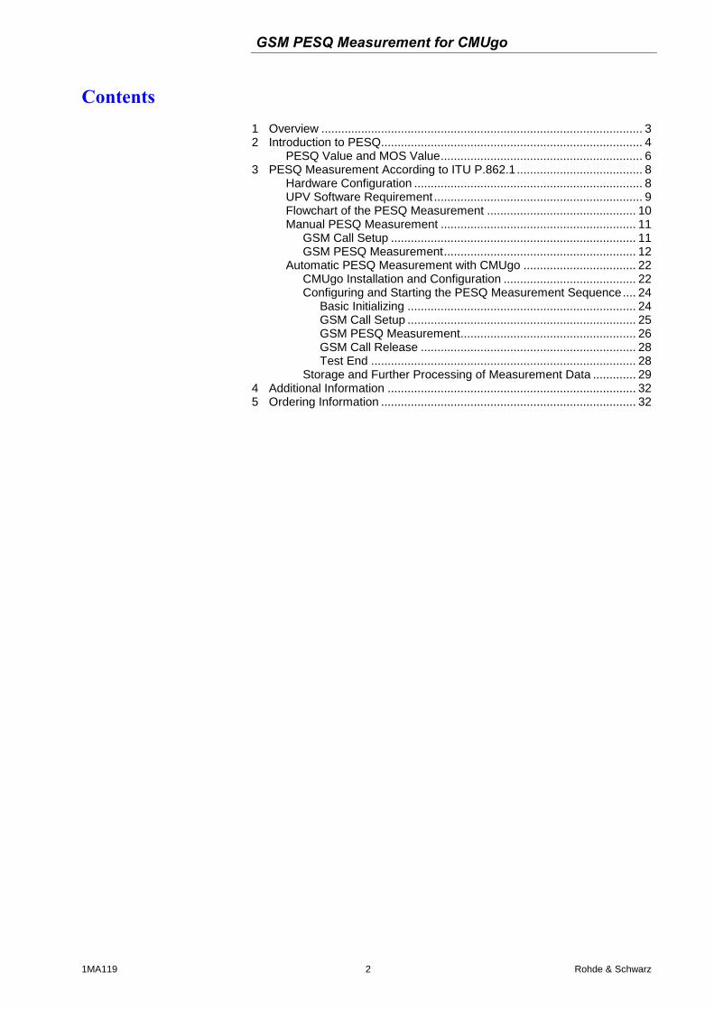
Contents 1 Overview ................................................................................................. 3 2 Introduction to PESQ............................................................................... 4
PESQ Value and MOS Value............................................................. 6 3 PESQ Measurement According to ITU P.862.1...................................... 8
Hardware Configuration ..................................................................... 8 UPV Software Requirement ............................................................... 9 Flowchart of the PESQ Measurement ............................................. 10 Manual PESQ Measurement ........................................................... 11
GSM Call Setup .......................................................................... 11 GSM PESQ Measurement.......................................................... 12
Automatic PESQ Measurement with CMUgo .................................. 22 CMUgo Installation and Configuration ........................................ 22 Configuring and Starting the PESQ Measurement Sequence.... 24
Basic Initializing ..................................................................... 24 GSM Call Setup ..................................................................... 25 GSM PESQ Measurement..................................................... 26 GSM Call Release ................................................................. 28 Test End ................................................................................ 28
Storage and Further Processing of Measurement Data ............. 29 4 Additional Information ........................................................................... 32 5 Ordering Information ............................................................................. 32
GSM PESQ Measurement for CMUgo
1MA119 3 Rohde & Schwarz
1 Overview Recent mobile test methods could not evaluate the quality of data re-duced speech signals with different coded and decoded signals. The Perceptual Evaluation of Speech Quality (PESQ) provides the solution for this measuring problem. GSM PESQ is an add-on tool for CMUgo for automatic measurement of the PESQ for GSM mobile phones ac-cording to recommendation ITU-T P.862 featuring selectable fading profiles, frequency hopping sequences and variable Additional White Gaussian Noise (AWGN). It features selectable fading profiles TU3, TU50 TU120 for 6 and 12 paths and variable Additional White Gaussian Noise (AWGN) for realistic receiving scenarios and frequency hopping sequences A, B, C and D for counteracting negative effect on the signal qualitity caused by fading.
The following abbreviations are used in the following text for R&S® test equipment:
The R&S® CMU200 Universal Radio Communication Tester is re-ferred to as CMU.
The R&S® SMU200A Vector Signal Generator is referred to as SMU.
The R&S® UPV Audio Analyzer is referred to as UPV.
R&S® refers to Rohde & Schwarz GmbH und Co KG
GSM PESQ Measurement for CMUgo
1MA119 4 Rohde & Schwarz
2 Introduction to PESQ The “Perceptual Evaluation of Speech Quality” (PESQ) measurement method, which was published by the International Telecommunications Union in 2001 as recommendation ITU-T P.862, enables measure-ments to be made on speech signals that are transmitted at low bit ra-tes using high compression psychoacoustic coding methods. PESQ employs an algorithm that enables these signals to be evaluated by comparing them with reference signals. The R&S UPV supports this measuring method, with the software licensed by Opticom GmbH in Er-langen (Germany).
A common feature of all psychoacoustic coding methods is that they utilize the properties of human hearing to clip the transmitted signal so that the portions of the signal that would in any case not be perceived are removed from the signal. Speech can be compressed more easily as other types of signals, since it occupies considerably less bandwidth. When speech compression is used, it is necessary to be able to deter-mine objectively, with the aid of psychoacoustic measuring methods, whether the speech transmission technique produces unacceptable de-gration of the percieving speech quality.
PESQ was developed using a large number of recordings containing sentences spoken by a variety of speakers in a variety of languages. The recordings were made using several different speech encoders with different levels of quality and with typical network transmission dis-turbances. In a series of listening tests, an adequate number of test lis-teners classified these examples on a speech quality scale ranging from 1 (bad) to 5 (excellent).
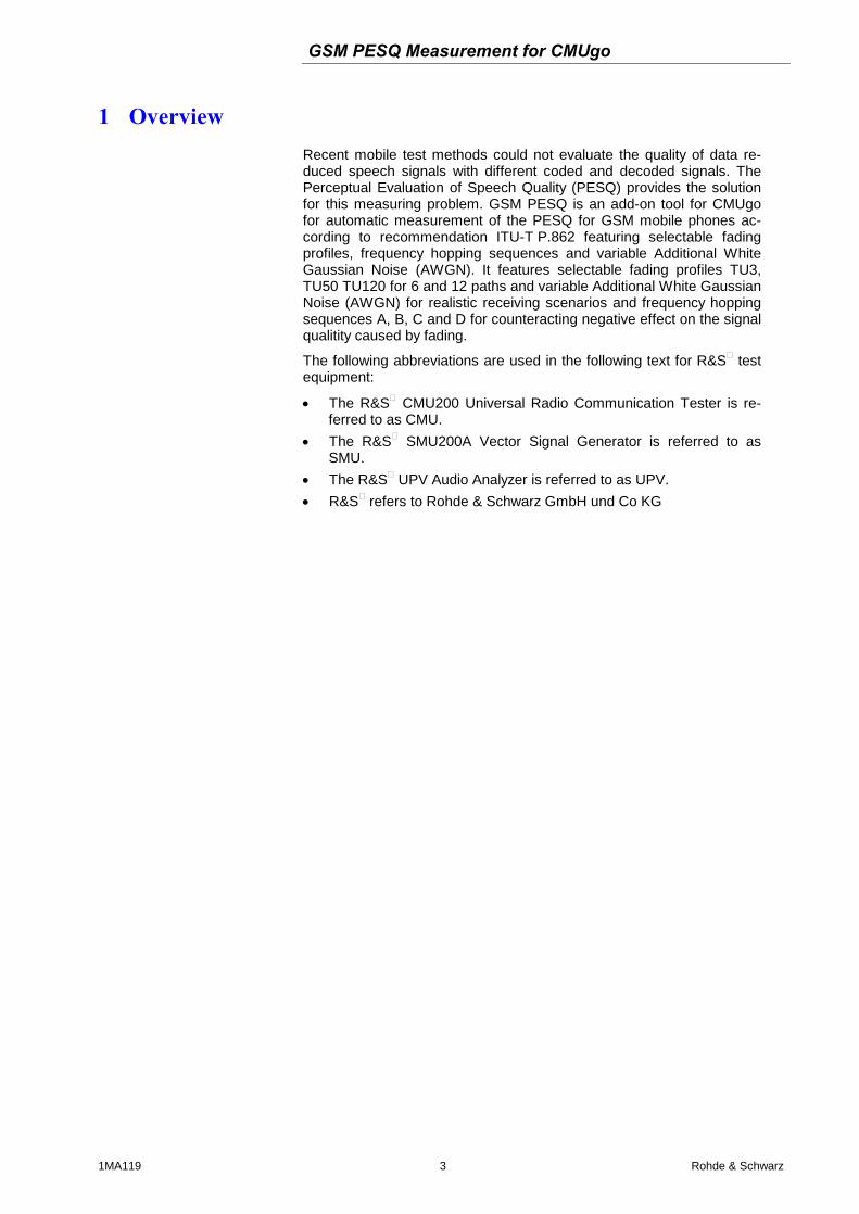
The goal in the development of PESQ was a method for determining an objective measurement that correlates very well with the listening test results, based on comparing the original, undegraded speech signal (the reference signal) with the degraded signal (the measured signal). To perform a PESQ measurement, the reference signal must be con-nected to the input of the system under test and the measurement sig-nal must be taken from the output of the system under test (see Fig. 2).
Fig. 1 Algorithm of PESQ Measurement in UPV
GSM PESQ Measurement for CMUgo
1MA119 5 Rohde & Schwarz
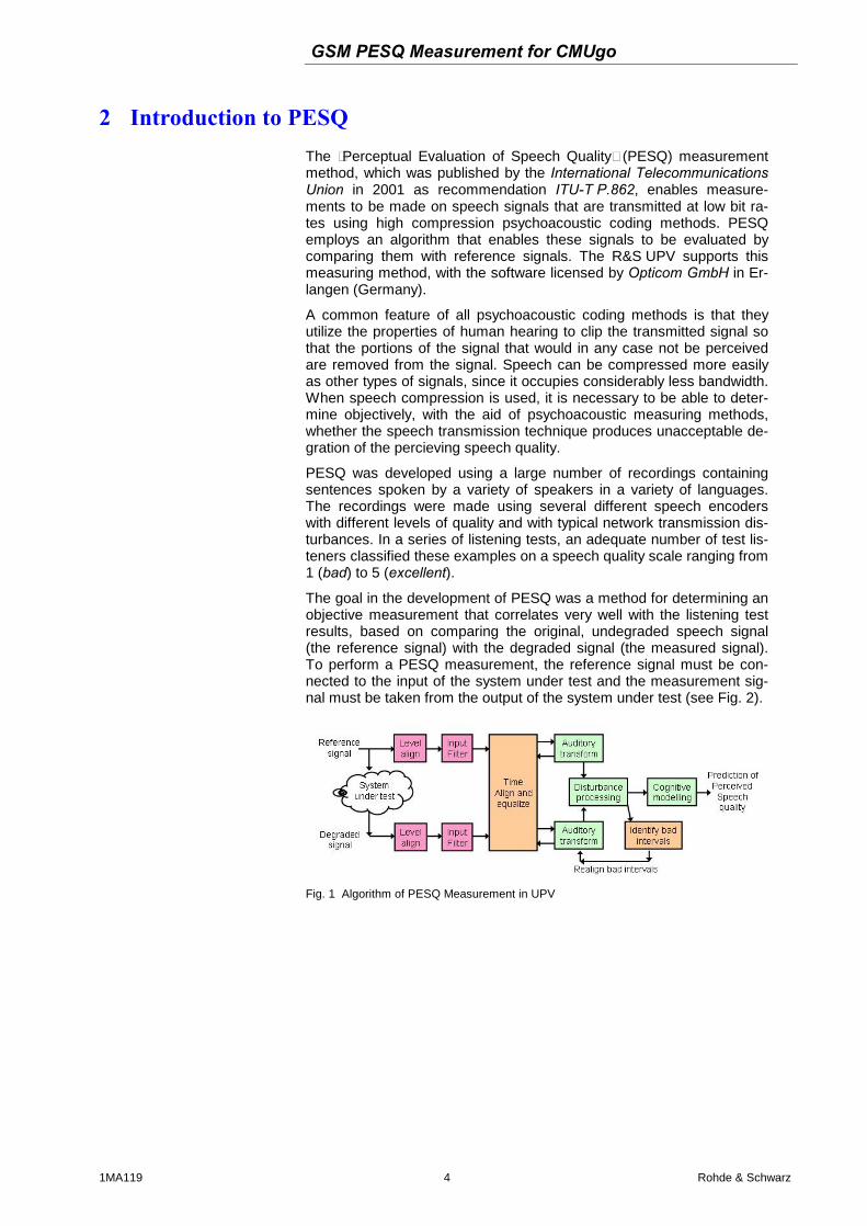
In Fig. 2 the R&S instruments involved in the PESQ measurement setup and their function is shown. The UPV provides the reference au-dio speech signal, the CMU modulates the baseband signal to RF which has been interfered by the SMU with fading and AWGN. The mobile phone demodulates the RF signal and supplies the degraded audio sig-nal (system under test). The UPV performs the PESQ measurement which determines the speech quality of the mobile phone receiver.
Earphone
RF2
SPEECH
Analyzer 1 Gene-rator 2
Modu-lator
Enco-der
CMU
UPV Ref
System Under Test
Reference Signal
Degraded Signal
SMU Fading,AWGN
Baseband In/Out
Fig. 2 PESQ Measurement Setup with R&S Instruments
GSM PESQ Measurement for CMUgo
1MA119 6 Rohde & Schwarz
PESQ Value and MOS Value
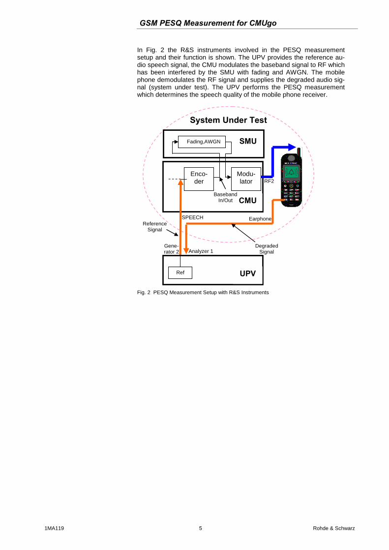
Over the course of time, the ITU has developed several different meth-ods for calculating objective measurements from the average values of the listening test results. This calculation is performed by using a map-ping function such as the example shown below.
Fig. 3 P.862 Algorithm's Mapping Function
The average values from the listening tests are plotted on the Y axis, and the associated PESQ values in accordance with ITU P862.1 are shown on the X axis. This constraint will help ensure that MOS-LQO scores from will be comparable for all implementations of ITU P.862.
The R&S UPV implements the three most important standards which differ only slightly from each other and have been approved by the ITU:
ITU P.862: The measured value is the “PESQ Score” or the “PESQ MOS” (Mean Opinion Score). The possible range is -0.5 (worst) to +4.5 (best). In addition, measurements can be made with reference to the speech component or the silence component of the signal. The latter is particularly interesting because it shows how well the codec replaces background noise.
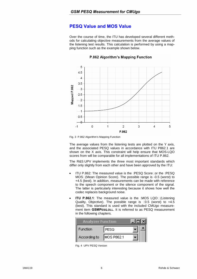
ITU P.862.1: The measured value is the “MOS LQO” (Listening Quality, Objective). The possible range is –0.5 (worst) to +4.5 (best). This standard is used with the included CMUgo measure-ment item GSMPESQ.DLL. It is referred to as PESQ measurement in the following chapters.
Fig. 4 UPV PESQ Version
GSM PESQ Measurement for CMUgo
1MA119 7 Rohde & Schwarz
ITU P.862.2: This is the wideband extension (bandwidth > 6.3 kHz) of P.862. The measured value is the “MOS”. The possible range is –0.5 (worst) to +4.5 (best). Note that measurements obtained using this option cannot be compared with results obtained in accordance with P.862 or P.862.1.
GSM PESQ Measurement for CMUgo
1MA119 8 Rohde & Schwarz
3 PESQ Measurement According to ITU P.862.1
Hardware Configuration
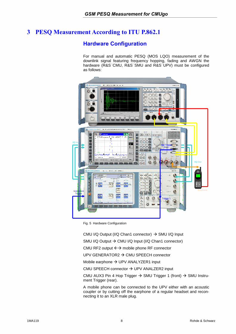
For manual and automatic PESQ (MOS LQO) measurement of the downlink signal featuring frequency hopping, fading and AWGN the hardware (R&S®CMU, R&S®SMU and R&S®UPV) must be configured as follows:
Hop Trigger Pin4
Trigger 1
Instrument Trigger
Earphone
I/Q Out
I/Q In
Fig. 5 Hardware Configuration
CMU I/Q Output (I/Q Chan1 connector) SMU I/Q Input
SMU I/Q Output CMU I/Q Input (I/Q Chan1 connector)
CMU RF2 output mobile phone RF connector
UPV GENERATOR2 CMU SPEECH connector
Mobile earphone UPV ANALYZER1 input
CMU SPEECH connector UPV ANALZER2 input
CMU AUX3 Pin 4 Hop Trigger SMU Trigger 1 (front) SMU Instru-ment Trigger (rear).
A mobile phone can be connected to the UPV either with an acoustic coupler or by cutting off the earphone of a regular headset and recon-necting it to an XLR male plug.
GSM PESQ Measurement for CMUgo
1MA119 9 Rohde & Schwarz
UPV Software Requirement
The UPV requires option UPV-K61 PESQ measurements. PESQ measurements require the CMU coder and decoder to be calibrated first by the UPV (See pages 13 and 14 for details). The macros DECODER.EXE and and ENCODER_PESQ.EXE must be installed with the included file CMUCAL_PESQ.MSI which needs to be copied to the UPV via USB Stick or LAN and executed on the UPV. In order to run the macros the Universal Sequence Controller option UPV-K1 needs to be installed on the UPV.
GSM PESQ Measurement for CMUgo
1MA119 10 Rohde & Schwarz
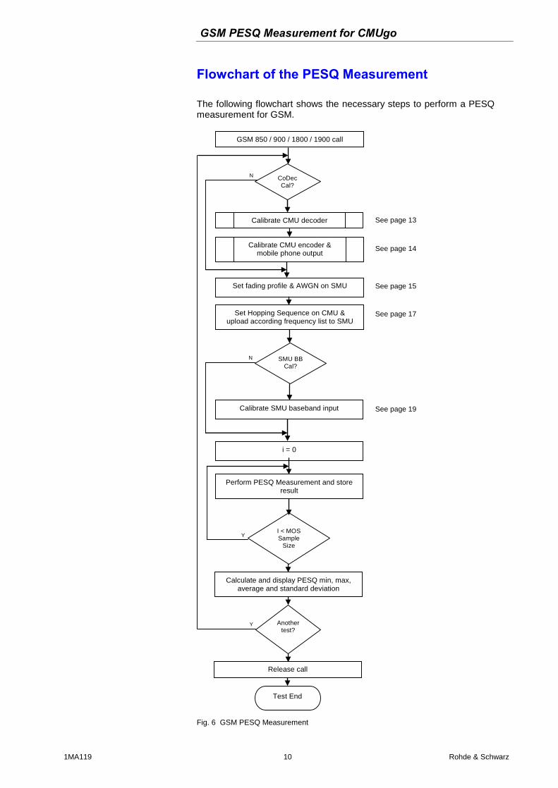
Flowchart of the PESQ Measurement
The following flowchart shows the necessary steps to perform a PESQ measurement for GSM.
N
Y
Y
GSM 850 / 900 / 1800 / 1900 call
CoDec Cal?
Calibrate CMU decoder
Calibrate CMU encoder & mobile phone output
Set fading profile & AWGN on SMU
i = 0
Perform PESQ Measurement and store result
I < MOS Sample
Size
Calculate and display PESQ min, max, average and standard deviation
Another test?
Release call
Test End
See page 13
See page 14
See page 15
See page 17
N SMU BB Cal?
Calibrate SMU baseband input See page 19
Set Hopping Sequence on CMU & upload according frequency list to SMU
Fig. 6 GSM PESQ Measurement
GSM PESQ Measurement for CMUgo
1MA119 11 Rohde & Schwarz
Manual PESQ Measurement The following section shows in detail the necessary steps to perform a PESQ measurement manually. In order to ensure repeatability of measurement results it is recommended to preset all instruments in-volved (CMU, SMU, UPV).
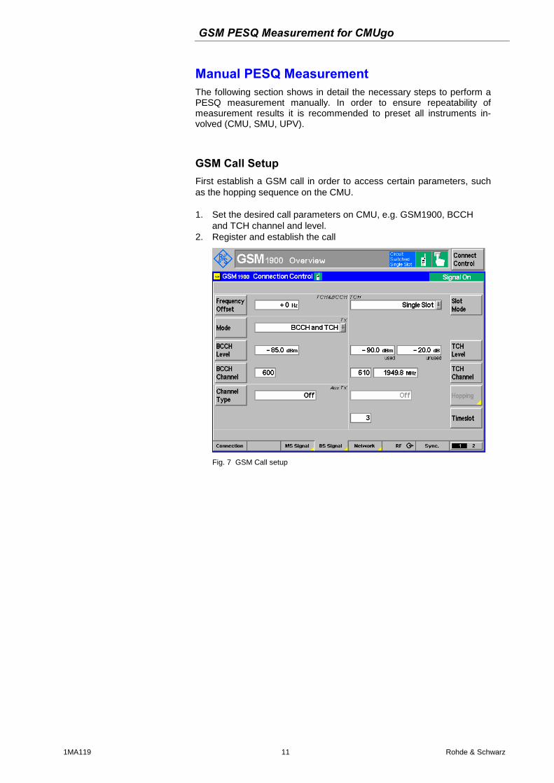
GSM Call Setup First establish a GSM call in order to access certain parameters, such as the hopping sequence on the CMU. 1. Set the desired call parameters on CMU, e.g. GSM1900, BCCH
and TCH channel and level. 2. Register and establish the call
Fig. 7 GSM Call setup
GSM PESQ Measurement for CMUgo
1MA119 12 Rohde & Schwarz
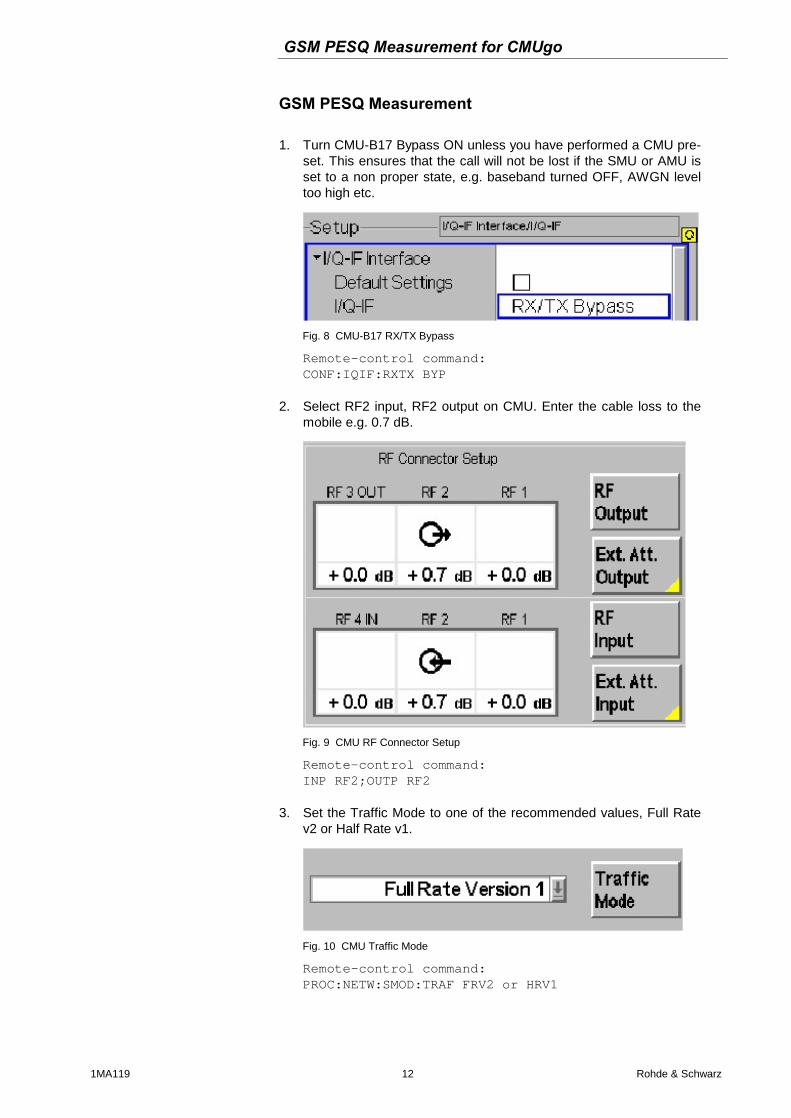
GSM PESQ Measurement 1. Turn CMU-B17 Bypass ON unless you have performed a CMU pre-
set. This ensures that the call will not be lost if the SMU or AMU is set to a non proper state, e.g. baseband turned OFF, AWGN level too high etc.
Fig. 8 CMU-B17 RX/TX Bypass
Remote-control command: CONF:IQIF:RXTX BYP
2. Select RF2 input, RF2 output on CMU. Enter the cable loss to the
mobile e.g. 0.7 dB.
Fig. 9 CMU RF Connector Setup
Remote-control command: INP RF2;OUTP RF2
3. Set the Traffic Mode to one of the recommended values, Full Rate
v2 or Half Rate v1.
Fig. 10 CMU Traffic Mode
Remote-control command: PROC:NETW:SMOD:TRAF FRV2 or HRV1
GSM PESQ Measurement for CMUgo
1MA119 13 Rohde & Schwarz
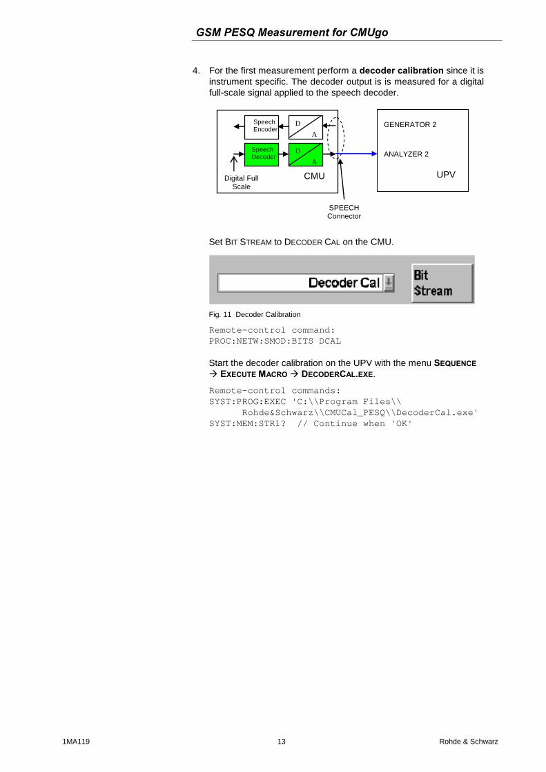
4. For the first measurement perform a decoder calibration since it is instrument specific. The decoder output is is measured for a digital full-scale signal applied to the speech decoder.
A
Speech Decoder
D
D
A
Speech Encoder
Digital Full Scale
CMU
SPEECH Connector
GENERATOR 2
ANALYZER 2
UPV
Set BIT STREAM to DECODER CAL on the CMU.
Fig. 11 Decoder Calibration
Remote-control command: PROC:NETW:SMOD:BITS DCAL Start the decoder calibration on the UPV with the menu SEQUENCE EXECUTE MACRO DECODERCAL.EXE.
Remote-control commands: SYST:PROG:EXEC 'C:\\Program Files\\ Rohde&Schwarz\\CMUCal_PESQ\\DecoderCal.exe' SYST:MEM:STR1? // Continue when 'OK'
GSM PESQ Measurement for CMUgo
1MA119 14 Rohde & Schwarz
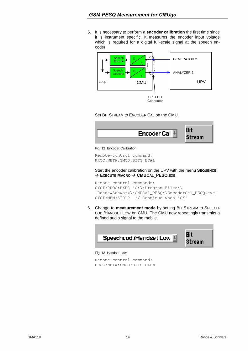
5. It is necessary to perform a encoder calibration the first time since it is instrument specific. It measures the encoder input voltage which is required for a digital full-scale signal at the speech en-coder.
A
Speech Decoder
D
D
A
Speech Encoder
Loop CMU
SPEECH Connector
GENERATOR 2
ANALYZER 2
UPV
Set BIT STREAM to ENCODER CAL on the CMU.
Fig. 12 Encoder Calibration
Remote-control command: PROC:NETW:SMOD:BITS ECAL Start the encoder calibration on the UPV with the menu SEQUENCE EXECUTE MACRO CMUCAL_PESQ.EXE.
Remote-control commands: SYST:PROG:EXEC 'C:\\Program Files\\ Rohde&Schwarz\\CMUCal_PESQ\\EncoderCal_PESQ.exe' SYST:MEM:STR1? // Continue when 'OK'
6. Change to measurement mode by setting BIT STREAM to SPEECH-
COD./HANDSET LOW on CMU. The CMU now repeatingly transmits a defined audio signal to the mobile.
Fig. 13 Handset Low
Remote-control command: PROC:NETW:SMOD:BITS HLOW
GSM PESQ Measurement for CMUgo
1MA119 15 Rohde & Schwarz
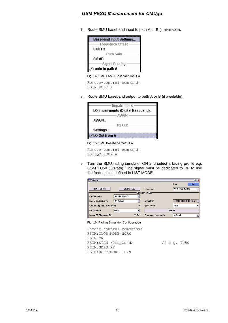
7. Route SMU baseband input to path A or B (if available).
Fig. 14 SMU / AMU Baseband Input A
Remote-control command: BBIN:ROUT A
8. Route SMU baseband output to path A or B (if available).
Fig. 15 SMU Baseband Output A
Remote-control command: BB:IQO:SOUR A
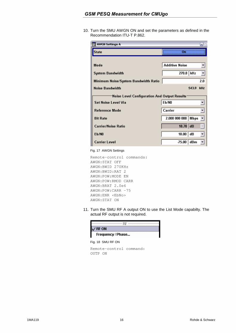
9. Turn the SMU fading simulator ON and select a fading profile e.g. GSM TU50 (12Path). The signal must be dedicated to RF to use the frequencies defined in LIST MODE.
Fig. 16 Fading Simulator Configuration
Remote-control commands: FSIM:ILOS:MODE NORM FSIM ON FSIM:STAN <PropCond> // e.g. TU50 FSIM:SDES RF FSIM:HOPP:MODE IBAN
GSM PESQ Measurement for CMUgo
1MA119 16 Rohde & Schwarz
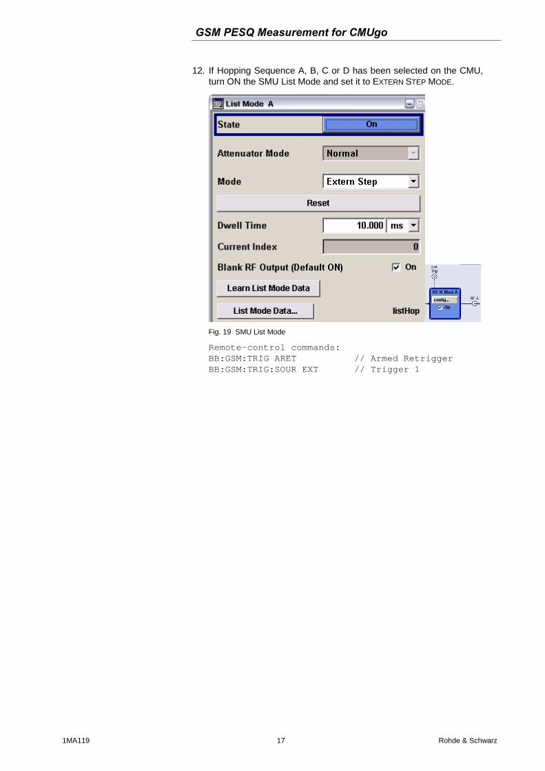
10. Turn the SMU AWGN ON and set the parameters as defined in the Recommendation ITU-T P.862.
Fig. 17 AWGN Settings
Remote-control commands: AWGN:STAT OFF AWGN:BWID 270KHz AWGN:BWID:RAT 2 AWGN:POW:MODE EN AWGN:POW:RMOD CARR AWGN:BRAT 2.0e6 AWGN:POW:CARR -75 AWGN:ENR <EbNo> AWGN:STAT ON
11. Turn the SMU RF A output ON to use the List Mode capabilty. The actual RF output is not required.
Fig. 18 SMU RF ON
Remote-control command: OUTP ON
GSM PESQ Measurement for CMUgo
1MA119 17 Rohde & Schwarz
12. If Hopping Sequence A, B, C or D has been selected on the CMU, turn ON the SMU List Mode and set it to EXTERN STEP MODE.
Fig. 19 SMU List Mode
Remote-control commands: BB:GSM:TRIG ARET // Armed Retrigger BB:GSM:TRIG:SOUR EXT // Trigger 1
GSM PESQ Measurement for CMUgo
1MA119 18 Rohde & Schwarz
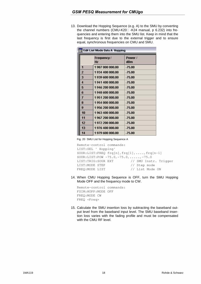
13. Download the Hopping Sequence (e.g. A) to the SMU by converting the channel numbers (CMU-K20…-K24 manual, p 6.232) into fre-quencies and entering them into the SMU list. Keep in mind that the last frequency is first due to the external trigger and to ensure equal, synchronous frequencies on CMU and SMU.
Fig. 20 SMU List for Hopping Sequence A
Remote-control commands: LIST:SEL ' Hopping' SOUR:LIST:FREQ frq[n],frq[1],....,frq[n-1] SOUR:LIST:POW -75.0,-75.0,.....,-75.0 LIST:TRIG:SOUR EXT // SMU Instr. Trigger LIST:MODE STEP // Step mode FREQ:MODE LIST // List Mode ON
14. When CMU Hopping Sequence is OFF, turn the SMU Hopping
Mode OFF and the frequency mode to CW.
Remote-control commands: FSIM:HOPP:MODE OFF FREQ:MODE CW FREQ <Freq>
15. Calculate the SMU insertion loss by subtracting the baseband out-
put level from the baseband input level. The SMU baseband inser-tion loss varies with the fading profile and must be compensated with the CMU RF level.
GSM PESQ Measurement for CMUgo
1MA119 19 Rohde & Schwarz
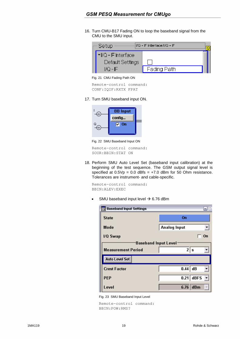
16. Turn CMU-B17 Fading ON to loop the baseband signal from the CMU to the SMU input.
Fig. 21 CMU Fading Path ON
Remote-control command: CONF:IQIF:RXTX FPAT
17. Turn SMU baseband input ON.
Fig. 22 SMU Baseband Input ON
Remote-control command: SOUR:BBIN:STAT ON
18. Perform SMU Auto Level Set (baseband input calibration) at the
beginning of the test sequence. The GSM output signal level is specified at 0.5Vp = 0.0 dBfs = +7.0 dBm for 50 Ohm resistance. Tolerances are instrument- and cable-specific.
Remote-control command: BBIN:ALEV:EXEC SMU baseband input level 6.76 dBm
Fig. 23 SMU Baseband Input Level
Remote-control command: BBIN:POW:RMS?
GSM PESQ Measurement for CMUgo
1MA119 20 Rohde & Schwarz
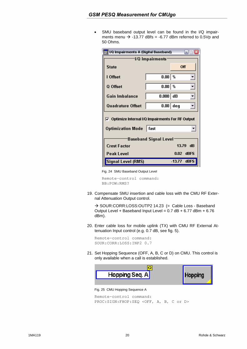
SMU baseband output level can be found in the I/Q impair-ments menu -13.77 dBfs = -6.77 dBm referred to 0.5Vp and 50 Ohms.
Fig. 24 SMU Baseband Output Level
Remote-control command: BB:POW:RMS?
19. Compensate SMU insertion and cable loss with the CMU RF Exter-
nal Attenuation Output control.
SOUR:CORR:LOSS:OUTP2 14.23 (= Cable Loss - Baseband Output Level + Baseband Input Level = 0.7 dB + 6.77 dBm + 6.76 dBm).
20. Enter cable loss for mobile uplink (TX) with CMU RF External At-
tenuation Input control (e.g. 0.7 dB, see fig. 5).
Remote-control command: SOUR:CORR:LOSS:INP2 0.7
21. Set Hopping Sequence (OFF, A, B, C or D) on CMU. This control is
only available when a call is established.
Fig. 25 CMU Hopping Sequence A
Remote-control command: PROC:SIGN:FHOP:SEQ <OFF, A, B, C or D>
GSM PESQ Measurement for CMUgo
1MA119 21 Rohde & Schwarz
22. Perform a PESQ measurement on the UPV (the parameters were already set by the decoder / encoder calibration, p.16).
Remote-control commands: INIT:CONT OFF;*WAI // Trigger measurement SENSe:DATA? // Read PESQ value The MOS sample count defines how many measurements must be taken so you should keep track of all the results. The actual PESQ value according to Recommendation ITU-T P.862 is the resulting average. It is also convenient to determine the minimum, maximum and standard deviation of a test.
GSM PESQ Measurement for CMUgo
1MA119 22 Rohde & Schwarz
Automatic PESQ Measurement with CMUgo
The R&S software tool CMUgo allows to generate custom test se-quences for the CMU plus one or more additional R&S instruments such as generators, analyzers, power meters, step attenuators. It offers automatic instrument configuration, test and documentation. The test results can be saved in several typical file formats, allowing post-processing with e.g. Excel, MatLAB etc.
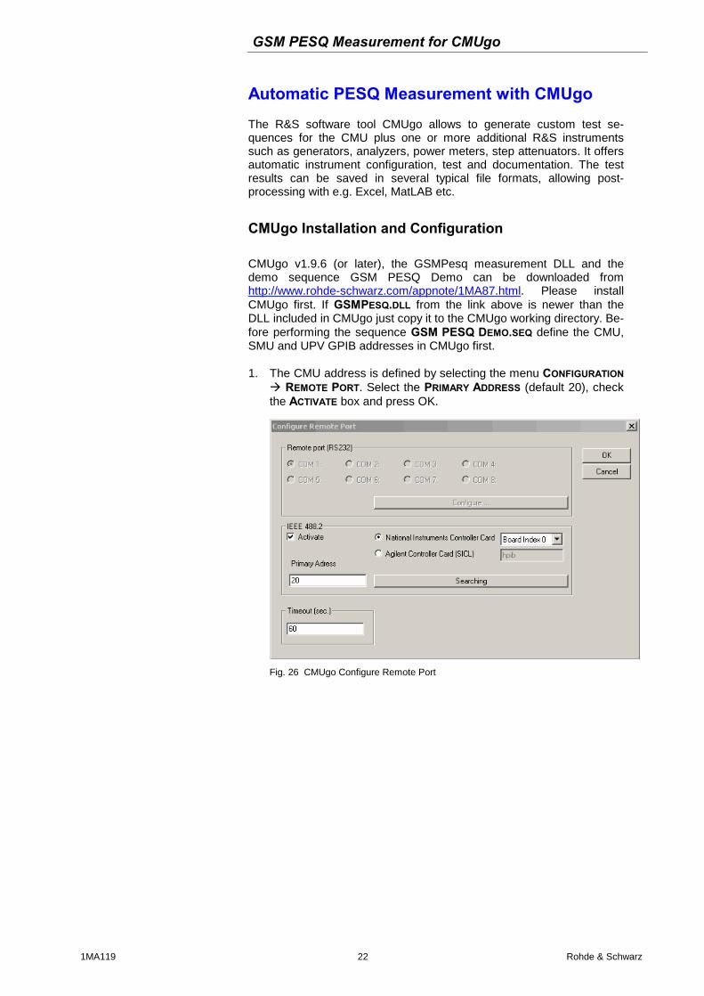
CMUgo Installation and Configuration CMUgo v1.9.6 (or later), the GSMPesq measurement DLL and the demo sequence GSM PESQ Demo can be downloaded from http://www.rohde-schwarz.com/appnote/1MA87.html. Please install CMUgo first. If GSMPESQ.DLL from the link above is newer than the DLL included in CMUgo just copy it to the CMUgo working directory. Be-fore performing the sequence GSM PESQ DEMO.SEQ define the CMU, SMU and UPV GPIB addresses in CMUgo first. 1. The CMU address is defined by selecting the menu CONFIGURATION
REMOTE PORT. Select the PRIMARY ADDRESS (default 20), check the ACTIVATE box and press OK.
Fig. 26 CMUgo Configure Remote Port
GSM PESQ Measurement for CMUgo
1MA119 23 Rohde & Schwarz
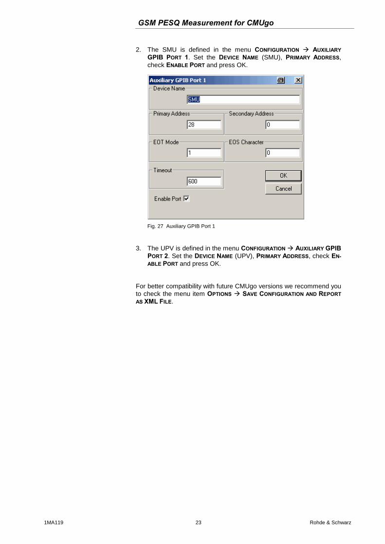
2. The SMU is defined in the menu CONFIGURATION AUXILIARY GPIB PORT 1. Set the DEVICE NAME (SMU), PRIMARY ADDRESS, check ENABLE PORT and press OK.
Fig. 27 Auxiliary GPIB Port 1
3. The UPV is defined in the menu CONFIGURATION AUXILIARY GPIB PORT 2. Set the DEVICE NAME (UPV), PRIMARY ADDRESS, check EN-ABLE PORT and press OK.
For better compatibility with future CMUgo versions we recommend you to check the menu item OPTIONS SAVE CONFIGURATION AND REPORT AS XML FILE.
GSM PESQ Measurement for CMUgo
1MA119 24 Rohde & Schwarz
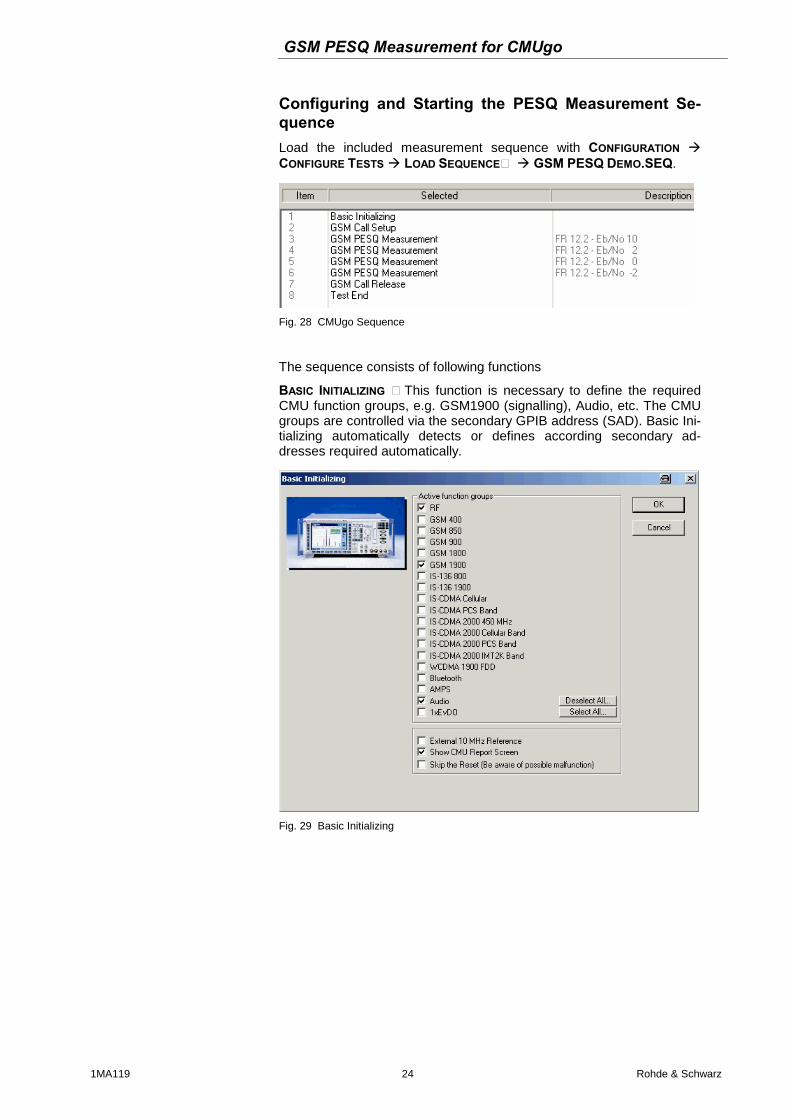
Configuring and Starting the PESQ Measurement Se-quence Load the included measurement sequence with CONFIGURATION CONFIGURE TESTS LOAD SEQUENCE… GSM PESQ DEMO.SEQ.
Fig. 28 CMUgo Sequence
The sequence consists of following functions
BASIC INITIALIZING – This function is necessary to define the required CMU function groups, e.g. GSM1900 (signalling), Audio, etc. The CMU groups are controlled via the secondary GPIB address (SAD). Basic Ini-tializing automatically detects or defines according secondary ad-dresses required automatically.
Fig. 29 Basic Initializing
GSM PESQ Measurement for CMUgo
1MA119 25 Rohde & Schwarz
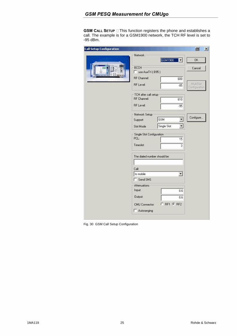
GSM CALL SETUP – This function registers the phone and establishes a call. The example is for a GSM1900 network, the TCH RF level is set to -95 dBm.
Fig. 30 GSM Call Setup Configuration
GSM PESQ Measurement for CMUgo
1MA119 26 Rohde & Schwarz
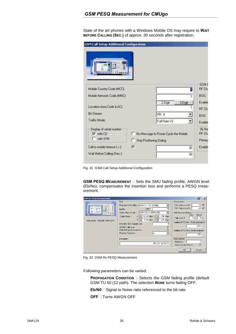
State of the art phones with a Windows Mobile OS may require to WAIT BEFORE CALLING (SEC.) of approx. 30 seconds after registration.
Fig. 31 GSM Call Setup Additional Configuration
GSM PESQ MEASUREMENT – Sets the SMU fading profile, AWGN level (Eb/No), compensates the insertion loss and performs a PESQ meas-urement.
Fig. 32 GSM Rx PESQ Measurement
Following parameters can be varied:
PROPAGATION CONDITION – Selects the GSM fading profile (default GSM TU 50 (12 path). The selection NONE turns fading OFF.
Eb/N0 – Signal to Noise ratio referenced to the bit rate.
OFF – Turns AWGN OFF
GSM PESQ Measurement for CMUgo
1MA119 27 Rohde & Schwarz
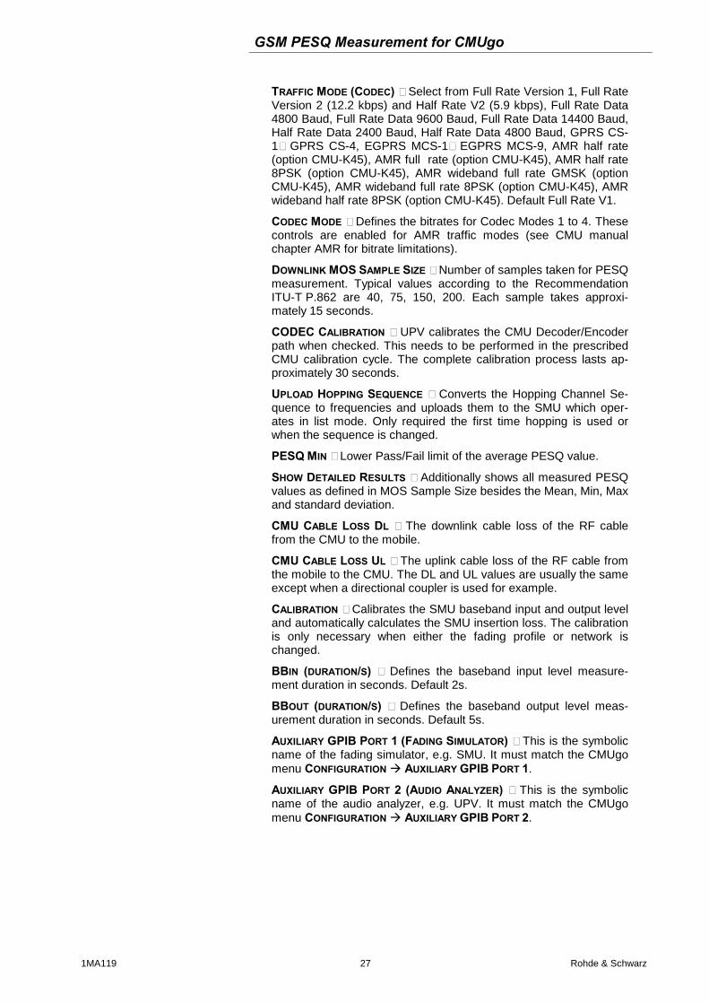
TRAFFIC MODE (CODEC) – Select from Full Rate Version 1, Full Rate Version 2 (12.2 kbps) and Half Rate V2 (5.9 kbps), Full Rate Data 4800 Baud, Full Rate Data 9600 Baud, Full Rate Data 14400 Baud, Half Rate Data 2400 Baud, Half Rate Data 4800 Baud, GPRS CS-1…GPRS CS-4, EGPRS MCS-1…EGPRS MCS-9, AMR half rate (option CMU-K45), AMR full rate (option CMU-K45), AMR half rate 8PSK (option CMU-K45), AMR wideband full rate GMSK (option CMU-K45), AMR wideband full rate 8PSK (option CMU-K45), AMR wideband half rate 8PSK (option CMU-K45). Default Full Rate V1.
CODEC MODE – Defines the bitrates for Codec Modes 1 to 4. These controls are enabled for AMR traffic modes (see CMU manual chapter AMR for bitrate limitations).
DOWNLINK MOS SAMPLE SIZE – Number of samples taken for PESQ measurement. Typical values according to the Recommendation ITU-T P.862 are 40, 75, 150, 200. Each sample takes approxi-mately 15 seconds.
CODEC CALIBRATION – UPV calibrates the CMU Decoder/Encoder path when checked. This needs to be performed in the prescribed CMU calibration cycle. The complete calibration process lasts ap-proximately 30 seconds.
UPLOAD HOPPING SEQUENCE – Converts the Hopping Channel Se-quence to frequencies and uploads them to the SMU which oper-ates in list mode. Only required the first time hopping is used or when the sequence is changed.
PESQ MIN – Lower Pass/Fail limit of the average PESQ value.
SHOW DETAILED RESULTS – Additionally shows all measured PESQ values as defined in MOS Sample Size besides the Mean, Min, Max and standard deviation.
CMU CABLE LOSS DL – The downlink cable loss of the RF cable from the CMU to the mobile.
CMU CABLE LOSS UL – The uplink cable loss of the RF cable from the mobile to the CMU. The DL and UL values are usually the same except when a directional coupler is used for example.
CALIBRATION – Calibrates the SMU baseband input and output level and automatically calculates the SMU insertion loss. The calibration is only necessary when either the fading profile or network is changed.
BBIN (DURATION/S) – Defines the baseband input level measure-ment duration in seconds. Default 2s.
BBOUT (DURATION/S) – Defines the baseband output level meas-urement duration in seconds. Default 5s.
AUXILIARY GPIB PORT 1 (FADING SIMULATOR) – This is the symbolic name of the fading simulator, e.g. SMU. It must match the CMUgo menu CONFIGURATION AUXILIARY GPIB PORT 1.
AUXILIARY GPIB PORT 2 (AUDIO ANALYZER) – This is the symbolic name of the audio analyzer, e.g. UPV. It must match the CMUgo menu CONFIGURATION AUXILIARY GPIB PORT 2.
GSM PESQ Measurement for CMUgo
1MA119 28 Rohde & Schwarz
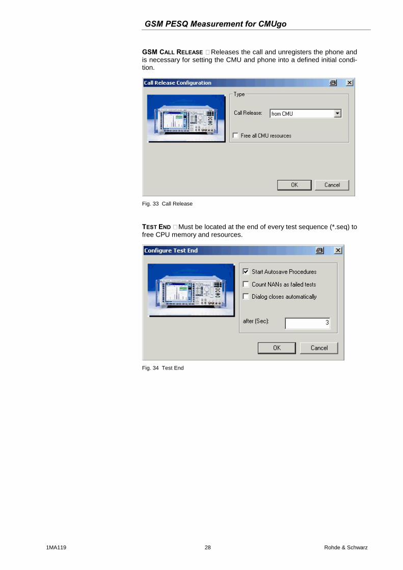
GSM CALL RELEASE – Releases the call and unregisters the phone and is necessary for setting the CMU and phone into a defined initial condi-tion.
Fig. 33 Call Release
TEST END – Must be located at the end of every test sequence (*.seq) to free CPU memory and resources.
Fig. 34 Test End
GSM PESQ Measurement for CMUgo
1MA119 29 Rohde & Schwarz
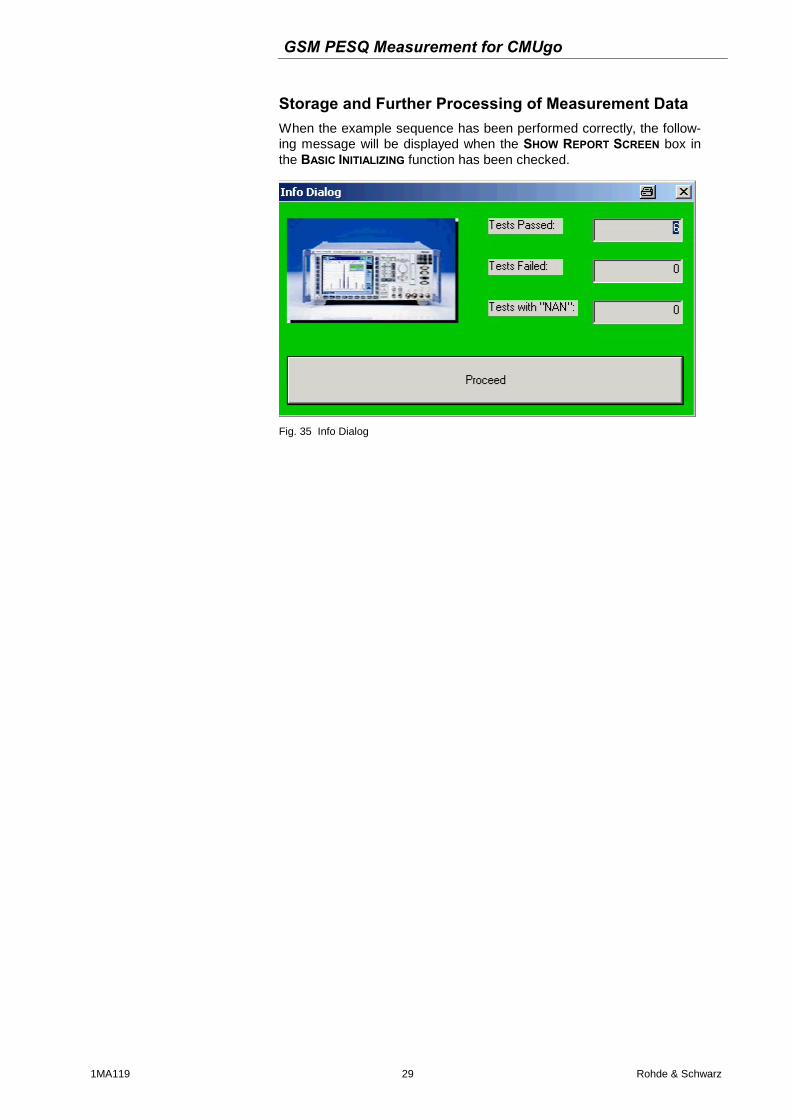
Storage and Further Processing of Measurement Data When the example sequence has been performed correctly, the follow-ing message will be displayed when the SHOW REPORT SCREEN box in the BASIC INITIALIZING function has been checked.
Fig. 35 Info Dialog
GSM PESQ Measurement for CMUgo
1MA119 30 Rohde & Schwarz
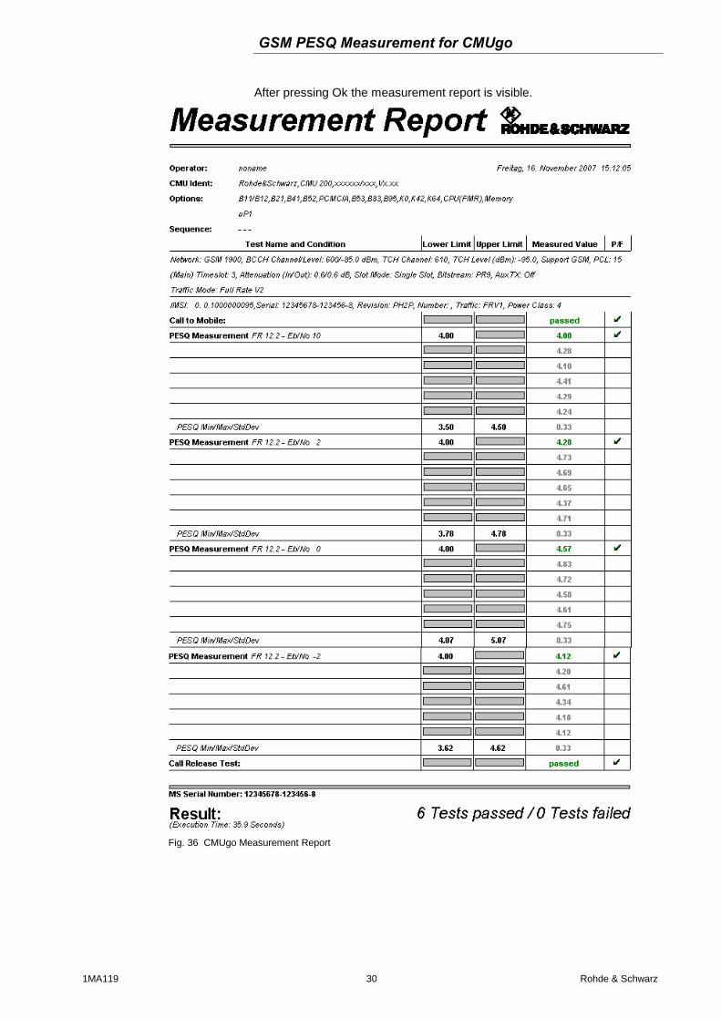
After pressing Ok the measurement report is visible.
Fig. 36 CMUgo Measurement Report
GSM PESQ Measurement for CMUgo
1MA119 31 Rohde & Schwarz
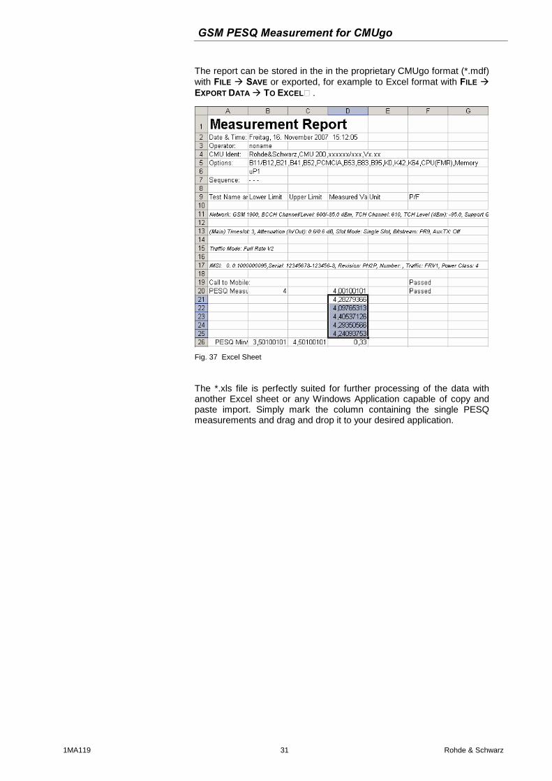
The report can be stored in the in the proprietary CMUgo format (*.mdf) with FILE SAVE or exported, for example to Excel format with FILE EXPORT DATA TO EXCEL….
Fig. 37 Excel Sheet
The *.xls file is perfectly suited for further processing of the data with another Excel sheet or any Windows Application capable of copy and paste import. Simply mark the column containing the single PESQ measurements and drag and drop it to your desired application.
GSM PESQ Measurement for CMUgo
1MA119 32 Rohde & Schwarz
4 Additional Information Please contact [email protected] for com-ments and further suggestions.
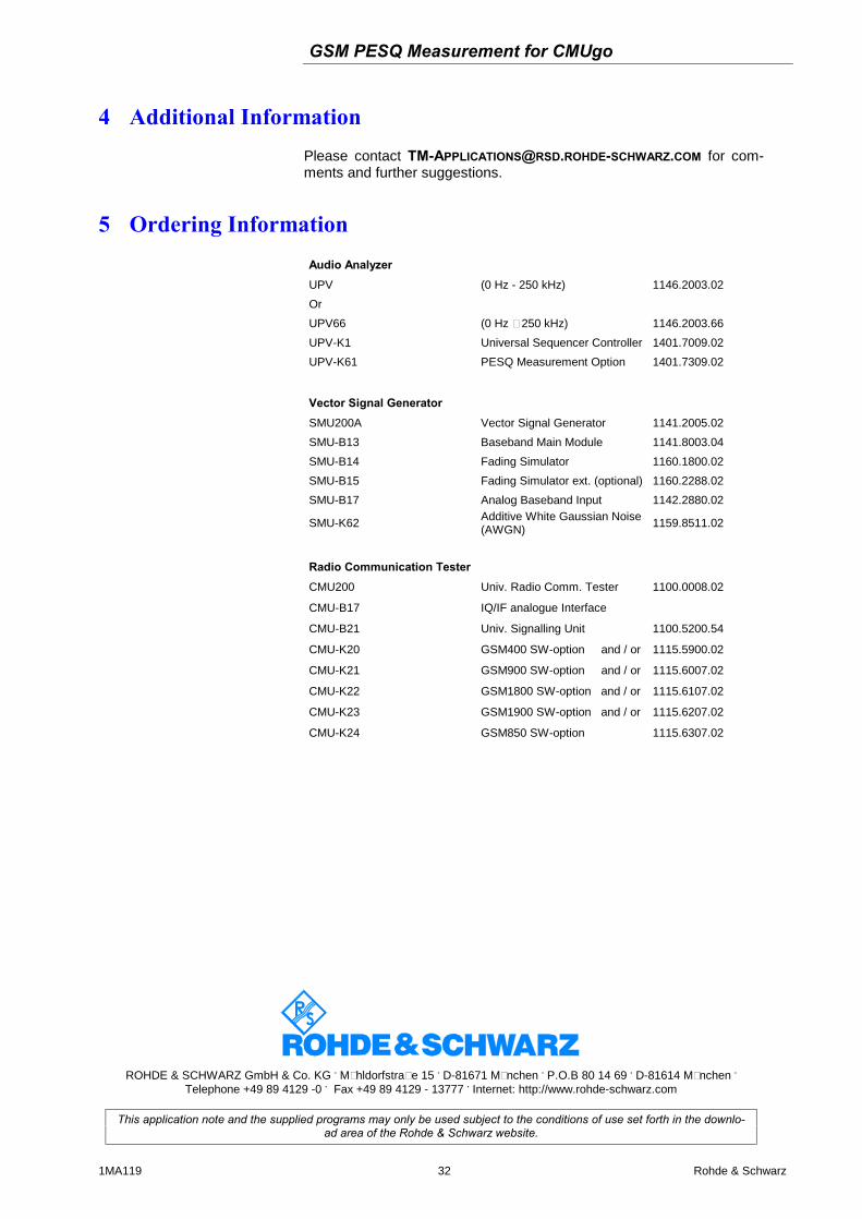
5 Ordering Information Audio Analyzer UPV (0 Hz - 250 kHz) 1146.2003.02
Or
UPV66 (0 Hz – 250 kHz) 1146.2003.66
UPV-K1 Universal Sequencer Controller 1401.7009.02
UPV-K61 PESQ Measurement Option 1401.7309.02
Vector Signal Generator SMU200A Vector Signal Generator 1141.2005.02
SMU-B13 Baseband Main Module 1141.8003.04
SMU-B14 Fading Simulator 1160.1800.02
SMU-B15 Fading Simulator ext. (optional) 1160.2288.02
SMU-B17 Analog Baseband Input 1142.2880.02
SMU-K62 Additive White Gaussian Noise (AWGN)
1159.8511.02
Radio Communication Tester CMU200 Univ. Radio Comm. Tester 1100.0008.02
CMU-B17 IQ/IF analogue Interface
CMU-B21 Univ. Signalling Unit 1100.5200.54
CMU-K20 GSM400 SW-option and / or 1115.5900.02
CMU-K21 GSM900 SW-option and / or 1115.6007.02
CMU-K22 GSM1800 SW-option and / or 1115.6107.02
CMU-K23 GSM1900 SW-option and / or 1115.6207.02
CMU-K24 GSM850 SW-option 1115.6307.02
ROHDE & SCHWARZ GmbH & Co. KG . Mühldorfstraße 15 . D-81671 München . P.O.B 80 14 69 . D-81614 München .
Telephone +49 89 4129 -0 . Fax +49 89 4129 - 13777 . Internet: http://www.rohde-schwarz.com
This application note and the supplied programs may only be used subject to the conditions of use set forth in the downlo-ad area of the Rohde & Schwarz website.