Embed Size (px)
Citation preview
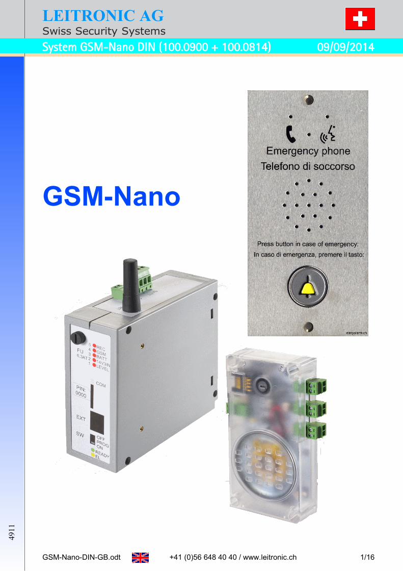
LEITRONIC AGSwiss Security Systems
System GSM-Nano DIN (100.0900 + 100.0814) 09/09/2014
GSM-Nano
GSM-Nano-DIN-GB.odt +41 (0)56 648 40 40 / www.leitronic.ch 1/16
4911

LEITRONIC AGSwiss Security Systems
System GSM-Nano DIN (100.0900 + 100.0814) 09/09/2014
Contents1 Overview.......................................................................................................................................... 32 Specification.....................................................................................................................................4
2.1 Communication unit Nano........................................................................................................42.1.1 Connectors........................................................................................................................4
2.2 EA-GSM-DIN............................................................................................................................52.2.1 Connectors........................................................................................................................5
3 Mounting.......................................................................................................................................... 63.1 Communication unit Nano........................................................................................................63.2 EA-GSM-DIN............................................................................................................................6
4 Wiring............................................................................................................................................... 75 Initial operation.................................................................................................................................8
5.1 Accessories..............................................................................................................................86 Indicators......................................................................................................................................... 9
6.1 EA-GSM-DIN............................................................................................................................96.2 Communication unit Nano........................................................................................................9
7 Programming over SMS.................................................................................................................107.1 Advanced settings..................................................................................................................107.2 Reply-SMS.............................................................................................................................117.3 Automatic Status-SMS............................................................................................................12
8 Troubleshooting.............................................................................................................................129 Reception test................................................................................................................................1310 Modem settings............................................................................................................................14
10.1 General settings...................................................................................................................1410.2 Specific elevator controls......................................................................................................14
11 Short instruction for alarm point....................................................................................................1511.1 Answering calls.....................................................................................................................1511.2 Callback into cabin................................................................................................................1511.3 Machine room communication..............................................................................................15
12 Maintenance protocol...................................................................................................................1612.1 Values of the reception test ( 9) note within each maintenance.........................................16
GSM-Nano-DIN-GB.odt +41 (0)56 648 40 40 / www.leitronic.ch 2/16

LEITRONIC AGSwiss Security Systems
System GSM-Nano DIN (100.0900 + 100.0814) 09/09/2014
1 Overview
The elevator alarm system GSM Nano is conform to EN81-28 and EN81-70. The connection between the communication unit Nano and the EA-GSM-DIN needs two wires
only (existing wires of alarm-horn may be used). The emergency call over GSM is a cost effective alternative to landline installation. No costs for an analogue landline. You may change the provider at any time. The elevator can already be used during construction. Programming over SMS (Calling numbers, identification and parameters). Connectivity for emergency button, misuse-protection-signal and external emergency light. Additional interface to connect to the elevator control (e.g. Böhnke & Partner, Newlift etc.) use
as GSM-Modem.
Safety note The location of the GSM-antenna should be stationary (e.g. in the machine room) in order that
a stable reception is guaranteed. In case of an emergency call retro-fit (SNEL, ESBA), where no empty wires in the hanging cable
are available, the EA-GSM-DIN can be located on top of the cabin, providing that the GSM re-ception is guaranteed for the entire cabin travel (Simple GSM reception diagnosis by SMS).
If the GSM reception is inadequate or fails completely, the elevator must automatically be set out of order: for example, command to the elevator control to move to the ground floor. There-fore the EA-GSM-DIN provides a relay contact (NO or NC).
Beware of using prepaid cards: in case of an emergency there might be no credit left. Better use a subscription or prepaid with topping up via auto reload.
To ensure that the correct number is dialled even with roaming, the calling numbers must be entered including the country code.
GSM-Nano-DIN-GB.odt +41 (0)56 648 40 40 / www.leitronic.ch 3/16

LEITRONIC AGSwiss Security Systems
System GSM-Nano DIN (100.0900 + 100.0814) 09/09/2014
2 Specification
2.1 Communication unit NanoArticle-No: 100.0900Power supply: from EA-GSM-DINDimension (L x W x D): 112 x 56 x 21 mmHousing: ABS transparentWeight: 100 g
LED indicator Comment
GreenFlashes every 5 seconds (1x=NO, 2x=NC): Nano is readyPermanent on: during voice connection
YellowDuring Misuse-protection, time-out and dial-up
2.1.1 ConnectorsComment
ECEmergency-contact
Potential free emergency-contact
Automatic detection of the contact type on power (e.g. voltage on LINE).NO = Normally open (1xPiep and every 5s a green flash)NC = Normally closed (2xPieps and every 5s a green double-flash)
LINE Connect communication unit over two wires with the EA-GSM-DIN.
Notes: Check polarity same polarity as on EA-GSM-DIN
If the polarity is wrong the emergency light is on continuously. For retro-fits you may use the existing two wires of the siren. The siren is
then connected to the EL output of the EA-GSM-DIN.MISUSE Misuse-protection door-signal-input: (active) = 10 to 50 V AC or DC
If during this time-out (= max. travel time) the door-signal changes, the emer-gency call will be stopped.
E_LEDEmergency-light
Emergency-light output for external LED: 6V DC / 20 mAThe emergency-light is on in case of a mains loss on the EA-GSM-DIN and in case of any failure 7.3.
SW = Slide switch. Switches between internal LED and external emergency-lightEXT e.g. for connecting an additional sub-communication unit EA-LMC70
Left detail
EXT SW E_LED
GSM-Nano-DIN-GB.odt +41 (0)56 648 40 40 / www.leitronic.ch 4/16
EXT
SW
E_LED
LINE
EC
MISUSE

LEITRONIC AGSwiss Security Systems
System GSM-Nano DIN (100.0900 + 100.0814) 09/09/2014
2.2 EA-GSM-DINArticle-No: 100.0814Power supply: 14.3 VDC +/- 0.15 V
Standby: 2.8 W + 1 W during connection+ load on 12VOUT+ load on EL+ 5 W during battery charge (max)
Backup battery: 12 V / 1.2 Ah (100.0880)Typical charging time: 8 h
GSM: Dual-Band 900/1800 MHz
Dimension (L x W x H): 45 x 118 x 138 mmHousing: DINWeight: 400 g (without battery)
2.2.1 ConnectorsComment
ANT GSM-Antenne SMA GSM-AntennaALM Alarm-input: active if signal 10 .. 50 V AC or DCBATT Connector for 12 V / 1.2 Ah
battery +BATT(red)-BATT (black)
EL +12V-Siren *)max. 250 mA
+EL (12V-Siren)-EL (12V-Siren)
EXT Serial interface For modem useFU Battery fuse 6.3 A slowLINE Connection to
communication unit Nano+LINE (Nano)-LINE (Nano)
14V3IN Supply voltage +14V3IN-14V3IN
READY Relay: Operation control:„System ready”
Normally open (NO)CNormally closed (NC)
SIM SIM-card holder Set SIM-PIN to 0000SW Mode switch OFF: GSM-Modem use only (transparent)
PROG: Programming of EA-GSM-DINON: Emergency call and GSM-Modem use
12VOUT Uninterrupted power supplymax. 250 mA
+12VOUT (UPS)-12VOUT (UPS)
*) the alarm-horn output is active, - as along as the emergency button is active - if the communication unit Nano is not connected- in case of any problem (short tone every 10 seconds, can be switched off 7.1)
GSM-Nano-DIN-GB.odt +41 (0)56 648 40 40 / www.leitronic.ch 5/16
LEITRONIC AGSwiss Security Systems
System GSM-Nano DIN (100.0900 + 100.0814) 09/09/2014
3 Mounting
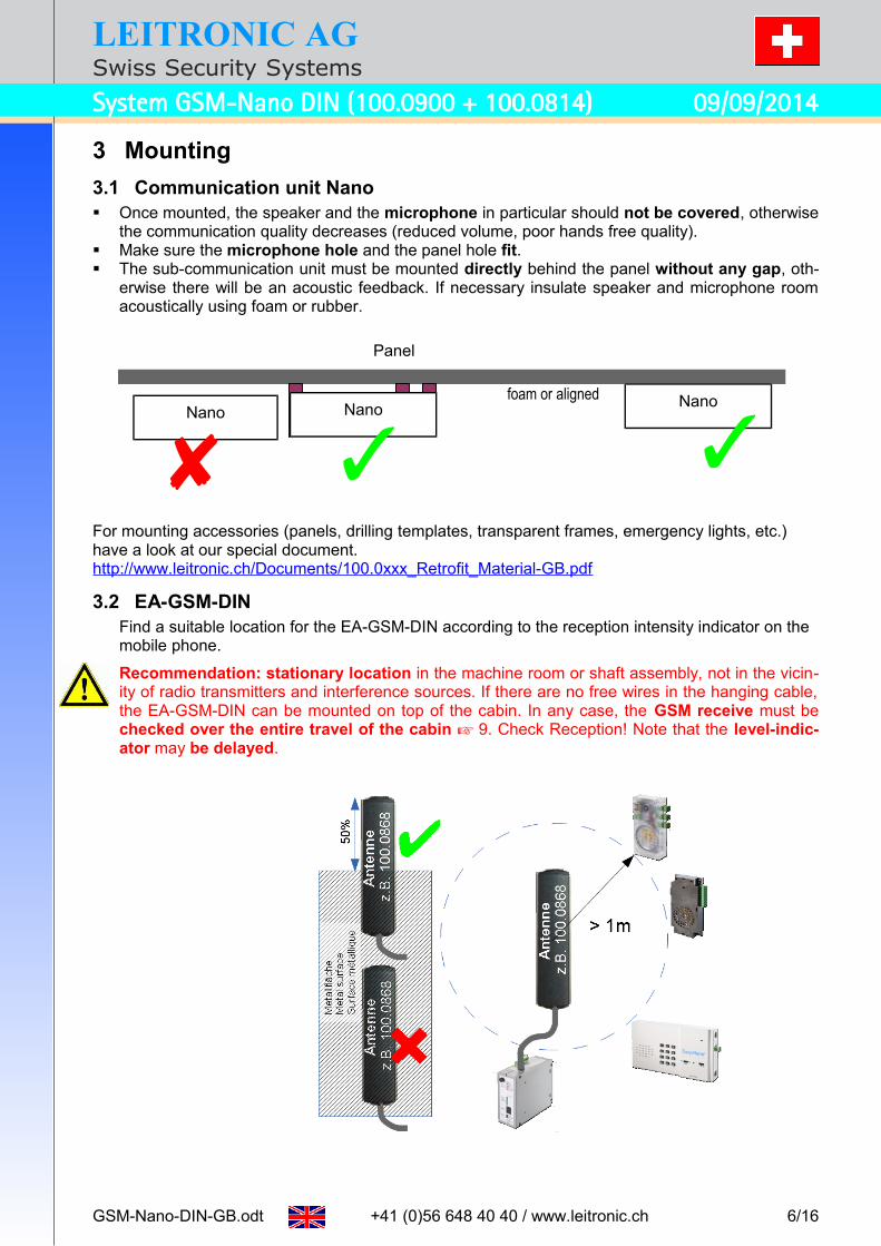
3.1 Communication unit Nano Once mounted, the speaker and the microphone in particular should not be covered, otherwise
the communication quality decreases (reduced volume, poor hands free quality). Make sure the microphone hole and the panel hole fit. The sub-communication unit must be mounted directly behind the panel without any gap, oth-
erwise there will be an acoustic feedback. If necessary insulate speaker and microphone room acoustically using foam or rubber.
For mounting accessories (panels, drilling templates, transparent frames, emergency lights, etc.) have a look at our special document.http://www.leitronic.ch/Documents/100.0xxx_Retrofit_Material-GB.pdf
3.2 EA-GSM-DINFind a suitable location for the EA-GSM-DIN according to the reception intensity indicator on the mobile phone.
Recommendation: stationary location in the machine room or shaft assembly, not in the vicin-ity of radio transmitters and interference sources. If there are no free wires in the hanging cable, the EA-GSM-DIN can be mounted on top of the cabin. In any case, the GSM receive must be checked over the entire travel of the cabin 9. Check Reception! Note that the level-indic-ator may be delayed.
GSM-Nano-DIN-GB.odt +41 (0)56 648 40 40 / www.leitronic.ch 6/16
Panel
foam or aligned NanoNano
Nano

LEITRONIC AGSwiss Security Systems
System GSM-Nano DIN (100.0900 + 100.0814) 09/09/2014
4 Wiring
GSM-Nano-DIN-GB.odt +41 (0)56 648 40 40 / www.leitronic.ch 7/16
Adjust RDT 10

LEITRONIC AGSwiss Security Systems
System GSM-Nano DIN (100.0900 + 100.0814) 09/09/2014
5 Initial operation• Connect communication unit, alarm-horn and emergency button according to wiring plan.• Optional machine-room communication using GSM-MR-Interface (100.0855): • Loop LINE-connection and connect 12V and MR-telephone.• Insert SIM-card with PIN set to 0000.
To set PIN to 0000 use any mobile phone.
**04* <old PIN>*0000*0000# + • Connect the battery 100.880.• Connect 14V3IN
◦ either from 230 VAC using DIN-adapter 118.0117.Work on the 230 VAC power supply must be carried out by a qualified electrician.Doing so the applicable accident prevention regulations must be observed, to avoid elec-tric shock, the mains has to be disconnected (trip the circuit breaker).
◦ or from 16 to 35 VDC using DIN-adapter 118.0118.• After two minutes the LEVEL indicators are showing the GSM reception. LED_COM flashes
green every 3 seconds. Stick the antenna where the LEDs LEVEL show maximum reception
• If you call NANO, the unit indicates sound while ringing and activating the green LED (speak). You may now record the individual announcement (identification) 11.
The calling-numbers can be programmed via SMS, by sending an SMS towards NANO 7.• A short pressing of the emergency button activates the alarm-horn. If you press longer
than the programmed debounce time-out, you will hear a dial tone during the selected misuse time-out.
• If there is no change of the MISUSE signal the first calling-number will be dialled.
5.1 AccessoriesPicture Supply Art.No.
DIN-Switching power supply EA-ACDC-USVSupply voltage: 230 VAC +-15% / 50 Hz, Output voltage: 14.3 VDC / 10 W
118.0117
DIN-Switching power supply EA-DCDC-USVSupply voltage: 9 to 35 VDC, Output voltage: 14.3 VDC / 10 W
118.0119
Battery 12 V / 1.2 Ah 100.0117, 100.080x and 100.081x 100.0880
Picture Antenna accessories for all GSM-modules 100.080x and 100.081x Art. No.
External GSM-Antenna cable 5m 100.0864
Antenna-Extension-cable cable 10m 100.0863
Picture Remote-communication unit to communicate with cabin Art. No.
GSM-MR (DIN-mounting, pluggable screw terminal and RJ12-jack)Machine room solution extension for DTMF capable telephone i.e. 118.0120
100.0855
Wall mount telephone incl. cable 3m machine room solution 118.0120
Picture Serial interface Art.No.
Data-Module DB9 serial interface for elevator controls DB9 100.0850
Data-Module USB interface for elevator controls MiniUSB 100.0851
Picture Other accessories Art.No.
EA-LMC70 (pluggable screw terminal and RJ45-jack)Supply voltage: 8 - 35 V DC i.e. +12V from EA-GSM-Interface or EA-GSM-DIN2xEN81-70 indicator (yellow/green): internal with light pipes, external symbols1xInput for emergency button: potential free
118.0155
LMC-EC (pluggable screw terminal and RJ45-jack) 1xEmergency-Button (Normally open: integrated or external)1xMicrophone + 1xSpeaker
118.0158
EC-MIC (screw terminal and RJ45-jacks)1xEmergency button 1xMicrophone
118.0152
12V-SIR siren horn 100.0020
GSM-Nano-DIN-GB.odt +41 (0)56 648 40 40 / www.leitronic.ch 8/16

LEITRONIC AGSwiss Security Systems
System GSM-Nano DIN (100.0900 + 100.0814) 09/09/2014
6 Indicators
6.1 EA-GSM-DINLED_COM Comment
GreenSIM-error: flashes every 1/2 secondDuring network registration: flashes every secondFlashes every 3 seconds if connected to the GSM network
Red Communication unit Nano connectedBlue Elevator control in connection: over serial interfaces
LEDNormally showing the GSM-reception level
In case of an error the LED shows error code1_LEVEL is inactive
LEVEL GSM Level poor Inactive LED2..5 showing errors *)14V3IN GSM Level low Problem with supply voltageBATT GSM Level medium Problem with battery/charging
GSM GSM Level highProblem with GSM-Network or Roamingor Nano not connected to LINE
REC GSM Level excellent Problem with GSM-reception (Level Alarm)
*) Error analysis by Status-SMS: send SMS with content„PIN:0000“ Reply-SMS 7.3
LED CommentEL Indicator of the alarm-horn output
OK (READY)
Ready-indicator for GSM-Interface, if Battery and battery-charging ok SIM-card inserted with correct SIM-PIN GSM-reception sufficient
Otherwise the elevator may not perform any further trips.Note: OK (READY) can be delayed up to two minutes (GSM-reception)
6.2 Communication unit NanoLED Comment
GreenFlashes every 5 seconds (1x=NO, 2x=NC): Nano is readyPermanent on: In voice connection
Yellow During Misuse-protection time-out and dial-up
GSM-Nano-DIN-GB.odt +41 (0)56 648 40 40 / www.leitronic.ch 9/16

LEITRONIC AGSwiss Security Systems
System GSM-Nano DIN (100.0900 + 100.0814) 09/09/2014
7 Programming over SMSProgramming is done by SMS. An SMS containing PIN:0000 will be evaluated and answered
7.2 to the sender. All commands are written in CAPITAL LETTERS.SMS-Commands Comment Reply-SMSPIN:0000 Default-PIN:0000
Note: PIN 4-digitsleitronic.ch Nano V.F.x.y ready
NEW:1234 Change PIN to 1234 and ac-tivate SIM-card protectionNote: PIN 4-digits
New Pin:1234
CALLNx=<Calling-No.>CALLN1 to CALLN9 will be called until DTMF 0 ac-knowledges call
Calling-numbers x=1..9 completed with a space(max. 24 digits)CALLN9 (Routine-No.)
CallNx:<Calling-number>
ALARM=<Alarm-number> Status-SMS numberwith +country code e.g. +41 completed with a space(max. 24 digits)
Alarm:<Alarm-number>
ALARM=OFF Disable Status-SMS Alarm:OFFRESET Set to factory defaults Reset
7.1 Advanced settings
Advanced settings can be read-out or changed as following:
EE_R:<adresse> Read EEPROM <adresse> is 4-digits
adr:<adresse>:<read out value>
EE_W:<adresse>=<value> Write EEPROM<adresse> is 4-digits<value> is 3-digits (000..255)
adr:<adresse>:<written value>
<adresse> Function <value> Default0001 Signal errors on alarm-horn 000 disabled
001 enabled001
0002 Connection time-out 030 to 255 s 120
0003 Debounce time: Emergency button (Nano) 000 to 255 * 20ms 050 = 1s
0018 Debounce time: Alarm-input ALM until Status-SMS
000 to 255 * 20ms 050 = 1s
0023 Routine call interval (CALLN9) 000 to 255 h 072
0024 Misuse protection time=max. cabin travel time 000 to 255 s 030
0127 Announcement every x seconds 000 off 001 to 255 s
000
Example:PIN=0000, Calling-No. 1: 044 111 22 33, Calling-No. 2: 044 111 22 44, Routine-No. 9: 044 123 45 567, Status-SMS: +41 79 100 10 10, max. cabin travel time= 20 s send SMS with contentPIN:0000 CALLN1=0041441112233 CALLN2=0041441112244 CALLN9=0041441234567 ALARM=+41791001010 EE_W:0024=020 Reply-SMSleitronic.ch Nano V.F.x.y ready, CallN1:0041441112233 CallN2:0041441112244, CallN9:0041441234567, Alarm:+41791001010, adr:0024:20, Batt:96, Ri:18, Charge:255, Power:34, last Call:26, Rssi:12(9-15), Ber:0(0-2), Errors:----+,-----,--- (limited to 160 characters)
GSM-Nano-DIN-GB.odt +41 (0)56 648 40 40 / www.leitronic.ch 10/16

LEITRONIC AGSwiss Security Systems
System GSM-Nano DIN (100.0900 + 100.0814) 09/09/2014
7.2 Reply-SMSExample of a Reply-SMS:leitronic.ch Nano V.F.x.y xx,(adr:<adresse>:<value>),(New Pin:<new PIN>), (Alarm:<alarm number>), Batt:xx, Ri:xx, Charge:xx, Power:xx, last Call:xx, Rssi:xx(xx-xx), Ber:xx(xx-xx), Errors:-----,-----,---
Label Comment Value xx InfoNano V.F.x.y
StatusSoftware-Version
readynot ready
System ready to use System not ready
Batt: Battery voltage 0 to 97 Calculate voltage: 0.145 * <value>e.g. 97 14.05V or 92 13.34V
Ri: Battery-resistance 10 to 70 10 – 23 battery o.k.defect! Battery- or Fuse F2
defect - Battery failure or blown fuse F2 6.3AT
check and replaceCharge: Battery charge value 0 to 255 Charge: * 255s / Discharge: * 15sPower: Battery charging
voltage 0 to 38 ≤ 25 supply voltage missing
≤ 28 supply voltage too low to charge bat-tery34 supply voltage sufficient
last Call:
Hours since last call 0 to 255 in hours
Roaming GSM-Roaming Not home GSM-network => higher costs Rssi: <mom>(<min>-<max>)
GSM-LevelMomentaryMin. since last callMax. since last call
0 to 31 Calculate level: 2*<Value> - 113dBe.g. 10 2*10-113 = -93dbGSM poor ≥ 5 LED1GSM low ≥ 10 LED2GSM medium ≥ 15 LED3GSM high ≥ 20 LED4GSM excellent ≥ 25 LED5
Ber: <mom>(<min>-<max>)
BitErrorRateMomentaryMin. since last callMax. since last call
0 to 7 0: minimum BitErrorRate7: maximum BitErrorRate
Errors Error-No. 0 to 12e.g. ----+,---*-,--*
- + * , -: inactive *: active ,: separator before error 5/10 +: delayed error not jet active
Example: Change PIN from 0000 to 1234, set Alarm to +41791234567, set EEPROM 0018 to 100 send SMS with contentPIN:0000 NEW:1234 ALARM=+41791234567 EE_W:0018=100 Reply-SMSleitronic.ch Nano V.F.x.y ready, New Pin:1234, Alarm:+41791234567, adr:0018:100, Batt:96, Ri:18, Charge:255, Power:34, last Call:26, Rssi:12(9-15), Ber:0(0-2), Errors:--*-+,-----,---
Error 2 active: GSM bad and Error 4: Supply voltage too low (in delay)
If you do not get any Reply-SMS, please check the following points:
a) EA-GSM-DIN is not connected to the GSM-network + check LED_GSM b) PIN-Code is incorrectc SIM number is incorrect d) No money left on SIM-card e) Mode switch SW1 not on ON
GSM-Nano-DIN-GB.odt +41 (0)56 648 40 40 / www.leitronic.ch 11/16

LEITRONIC AGSwiss Security Systems
System GSM-Nano DIN (100.0900 + 100.0814) 09/09/2014
7.3 Automatic Status-SMSThe Status-SMS will be sent to the defined alarm-number ALARM= , completed with a space.
To disable the Status-SMS send SMS with content: PIN:0000 ALARM=OFF
Example:Signal on input ALM SMS with content: leitronic.ch Nano V.F.x.y ready, Alarm X4, Batt:96, Ri:18, Charge:255, Power:34, last Call:26, Rssi:12(9-15), Ber:0(0-2) Errors:*----,-----,---
Err
ors
< State / Error>
RE
AD
Y (
OK
)
Em
erg
ency
ligh
t
Del
aye
d
Se
nd A
larm
SM
S c
on
ten
t
Error code LED
off could be on on
Te
st in
terv
al
Se
nd R
est
ore
Re
sto
re-S
MS
co
nte
nt
1 2 3 4 5
0 Alarm X4 / ALM Off 0 Alarm X4 (50)*20ms
- No Alarm X4
1 Supply voltage missing On 0 - Power off - Power on
2 GSM poor On 15 s GSM poor 2 s - GSM ok
3 GSM Roaming On 0 Roaming 2 s - Home
4Supply voltage too low to charge battery
On 15 s Power poor Power not poor
5No call within routine interval
On 0 No routine call
(74)
h- Routine call ok
6 Unacknowledged calls On 0 Emergency Call
Emergency ended *)
7Battery not charged within 24 h
On 0 Charge problem
24 h Charge ok
8
No or bad battery or fuse F2 defect or bat-tery test circuit defect (Ri<10)
On 0 Battery failure
1h Battery ok
9 GSM bad On 15 s GSM bad 2 s GSM ok
10No GSM network or not registered or mode switch SW1 not on ON
On 0 No GSM GSM registered
11 Nano not connected On 0 Line problem 1 h Line OK
12 Battery end Off 0 Battery end 2 s Charging
*) Emergency ended: Door-state changes / Alarm acknowledged by DTMF 0 / New connection
8 TroubleshootingFaults and errors are displayed by the various indicators (LED) Fehler: Referenz nicht gefunden
Detailed error information available through a status inquiry via SMS or automatically by Status-SMS in case of a new error (if <Send Alarm> is Table) send SMS with contentPIN:0000 Reply-SMS 7.3
GSM-Nano-DIN-GB.odt +41 (0)56 648 40 40 / www.leitronic.ch 12/16

LEITRONIC AGSwiss Security Systems
System GSM-Nano DIN (100.0900 + 100.0814) 09/09/2014
9 Reception test1. If the EA-GSM-DIN is mounted on the cabin roof, send the cabin to the location with the
worst GSM reception (check reception with LED1. .5). Attention: The level-indicator may be delayed.
2. Start test call and check if the connection is established terminate test call.3. Re-start test call + Connection must be established + Stay in connection and move the
cabin over the complete shaft Check if connection remains stable + Terminate test call + Send SMS to verify GSM-levels: Rssi:<mom>(<min>-<max>) The minimum value <min> must be higher than 5! Report Rssi-Value with date (see last page)!
4. If a problem occurred during test, change or optimize the placement of the EA-GSM-DIN.5. If you cannot find an improved placement use an external antenna e.g. Article-no 100.0864
and / or extension cord 100.0863.
GSM-Nano-DIN-GB.odt +41 (0)56 648 40 40 / www.leitronic.ch 13/16
LEITRONIC AGSwiss Security Systems
System GSM-Nano DIN (100.0900 + 100.0814) 09/09/2014
10 Modem settings
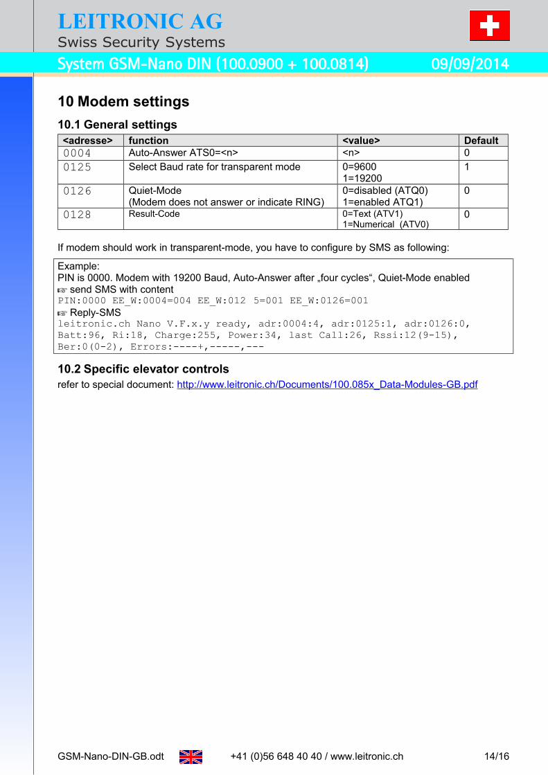
10.1 General settings<adresse> function <value> Default0004 Auto-Answer ATS0=<n> <n> 0
0125 Select Baud rate for transparent mode 0=96001=19200
1
0126 Quiet-Mode (Modem does not answer or indicate RING)
0=disabled (ATQ0)1=enabled ATQ1)
0
0128 Result-Code 0=Text (ATV1)1=Numerical (ATV0)
0
If modem should work in transparent-mode, you have to configure by SMS as following:
Example: PIN is 0000. Modem with 19200 Baud, Auto-Answer after „four cycles“, Quiet-Mode enabled send SMS with contentPIN:0000 EE_W:0004=004 EE_W:012 5=001 EE_W:0126=001 Reply-SMSleitronic.ch Nano V.F.x.y ready, adr:0004:4, adr:0125:1, adr:0126:0, Batt:96, Ri:18, Charge:255, Power:34, last Call:26, Rssi:12(9-15), Ber:0(0-2), Errors:----+,-----,---
10.2 Specific elevator controlsrefer to special document: http://www.leitronic.ch/Documents/100.085x_Data-Modules-GB.pdf
GSM-Nano-DIN-GB.odt +41 (0)56 648 40 40 / www.leitronic.ch 14/16

LEITRONIC AGSwiss Security Systems
System GSM-Nano DIN (100.0900 + 100.0814) 09/09/2014
11 Short instruction for alarm point
11.1 Answering callsAccept call Indication on communication unit
The called party can initiate the following remote-commands:
DTMF key Comment0 Terminate call
1 or 3 Renew connection for another 120 seconds
2 Play individual announcement (Identification)
8 In case of an alarm call: Terminate connection and call next alarm-numberIn case of callback into cabin: Terminate connection and call number 8
**# Record individual announcement (12 seconds).After recording the new text will be announced.
Each call must be terminated by key 0. Otherwise GSM-Nano calls the next alarm-number. If the alarm remains unacknowledged, a Status-SMS will be sent with contents:
leitronic.ch Nano V.F.x.y ready, Emergency Call, Batt:96, Ri:18, Charge:255, Power:34, last Call:26, Rssi:12(9-15), Ber:0(0-2) Errors:-----,*----,---
If there is a change of the door-state a Restore-SMS will be sent:
leitronic.ch Nano V.F.x.y ready, Emergency ended, Batt:96, Ri:18, Charge:255, Power:34, last Call:26, Rssi:12(9-15), Ber:0(0-2) Errors:-----,*----,---
11.2 Callback into cabinCall telephone number of the GSM-Nano. Ten seconds later you are connected with the cabin Indicated in the cabin by
11.3 Machine room communicationTo speak with the cabin lift handset and press key 1 .
Indicated in the cabin by:
To terminate communication press key 0 and set handset on-hook.
DTMF key Comment0 Terminate call
1 or 3 Speak with the cabin
4 Activate output EL to test siren
6 Deactivate output EL
GSM-Nano-DIN-GB.odt +41 (0)56 648 40 40 / www.leitronic.ch 15/16
LEITRONIC AGSwiss Security Systems
System GSM-Nano DIN (100.0900 + 100.0814) 09/09/2014
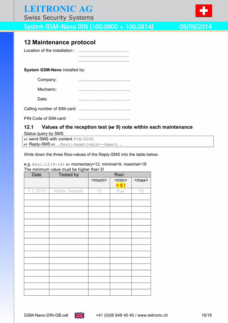
12 Maintenance protocolLocation of the installation : ………………………………
………………………………………………………………
System GSM-Nano installed by:
Company: ……………………………….
Mechanic: ……………………………….
Date: ……………………………….
Calling number of SIM-card: ……………………………….
PIN-Code of SIM-card: ……………………………….
12.1 Values of the reception test ( 9) note within each maintenanceStatus query by SMS send SMS with content PIN:0000 Reply-SMS .. Rssi:<mom>(<min>-<max>) ..
Write down the three Rssi-values of the Reply-SMS into the table below:
e.g. Rssi:12(9-18) momentary=12, minimal=9, maximal=18The minimum value must be higher than 5!
Date Tested by Rssi:<mom> <min>
> 5 !<max>
1.1.2010 Mister Sample 15 9 18
GSM-Nano-DIN-GB.odt +41 (0)56 648 40 40 / www.leitronic.ch 16/16