Embed Size (px)
Citation preview

Jan 2017 rev 1.2
GSM-PRO2
Instruction ManualInstruction ManualInstruction ManualInstruction Manual
GSM-PRO2
ContentsContentsContentsContents
1 DESCRIPTION ................................................................................................................ 4
1.1 Summary .................................................................................................................................. 4
1.2 Safety instructions ............................................................................................................ 4
2 SOFTWARE .................................................................................................................... 5
2.1 System requirements ................................................................................................................ 5
2.2 Software installation ................................................................................................................. 5
3 MODULE ....................................................................................................................... 6
3.1 Place the SIM card .................................................................................................................... 6
3.2 Connect the antenna ................................................................................................................ 7
3.3 Connect to power .................................................................................................................... 7
3.4 Connect to PC .......................................................................................................................... 8
3.5 LED description ........................................................................................................................ 8
3.5.1 Module status indication ....................................................................................................8
4 CONFIGURATION ......................................................................................................... 9
4.1 Connect to the GSM-PRO2 ....................................................................................................... 9
4.2 Configuration ......................................................................................................................... 10
4.2.1 Upload to the module ......................................................................................................10
4.2.2 Download from module ...................................................................................................10
4.2.3 Import / Export settings ....................................................................................................10
4.2.4 OTA configuration ............................................................................................................10
4.2.5 Reset module to default ....................................................................................................11
4.3 Diagnostics ............................................................................................................................. 12
4.3.1 Signal quality ...................................................................................................................12
4.4 Contacts ................................................................................................................................. 13
4.4.1 Add/delete contacts .........................................................................................................13
Import / Export contacts ...............................................................................................................13
5 SETTINGS .................................................................................................................... 14
5.1 Main settings .......................................................................................................................... 14
5.2 Mobile Data ............................................................................................................................ 14
5.3 Roaming ................................................................................................................................. 14
5.4 App 14
5.5 APN settings ........................................................................................................................... 14
5.6 SMTP ...................................................................................................................................... 14
GSM-PRO2
6 GENERAL MESSAGES ................................................................................................... 15
6.1.1 Periodical message ...........................................................................................................15
6.1.2 Power cycle message ........................................................................................................15
6.1.3 Power down message ......................................................................................................15
6.1.4 GSM connection loss message .........................................................................................15
6.1.5 Recipients .........................................................................................................................15
6.1.6 Additional messages .........................................................................................................15
7 LOG ............................................................................................................................ 16
7.1 Log 16
7.1.1 Event log ..........................................................................................................................16
7.1.2 AI log ...............................................................................................................................16
8 SOFTWARE UPDATES .................................................................................................. 17
8.1 Update ................................................................................................................................... 17
8.1.1 Manual firmware updates ................................................................................................17
8.1.2 OTA firmware update .......................................................................................................17
9 I/O CONFIGURATION AND MESSAGING ..................................................................... 18
9.1 Digital Output ........................................................................................................................ 18
9.1.1 Configuration ...................................................................................................................18
9.1.2 Select users ......................................................................................................................18
9.1.3 Messaging ........................................................................................................................18
9.1.3.1 Number ID ...............................................................................................................18
9.1.3.2 User defined instructions ..........................................................................................18
9.1.3.3 Change the digital output status ..............................................................................18
9.1.4 Using the one-shot function .............................................................................................19
9.1.5 React on RING ..................................................................................................................19
9.1.6 Link DO to DI ...................................................................................................................19
9.1.7 Activate when GSM connection is lost ..............................................................................19
9.1.8 Preserve status on startup .................................................................................................19
9.1.9 Wiring example ................................................................................................................19
9.2 Universal Inputs ...................................................................................................................... 20
9.2.1 Select receivers .................................................................................................................20
9.2.2 Confirmation sequence ....................................................................................................20
9.3 Analog inputs ......................................................................................................................... 20
9.3.1 Configuration ...................................................................................................................20
9.3.2 Wiring example ................................................................................................................21
9.4 Digital Inputs .......................................................................................................................... 22
9.4.1 Configuration ...................................................................................................................22
9.4.2 Wiring example ................................................................................................................22
9.5 Read all IO statuses ................................................................................................................. 23
9.6 Link multiple GSM-PRO2’s ...................................................................................................... 23
9.7 IO operating hours counter .................................................................................................... 23
GSM-PRO2
9.7.1 Request digital output counter .........................................................................................23
9.7.2 Request digital input counter ...........................................................................................23
9.7.3 Reset digital output counter .............................................................................................23
9.7.4 Reset digital input counter................................................................................................24
10 EXTENSIONS ............................................................................................................... 25
10.1 Configuration ......................................................................................................................... 25
10.1.1 Hardware .....................................................................................................................25
10.1.2 Software ......................................................................................................................25
10.2 GSM-PRO-4DO ....................................................................................................................... 26
10.3 GSM-PRO-10DI ....................................................................................................................... 26
10.4 GSM-PRO-8AI ......................................................................................................................... 27
10.4.1 Configuration ...............................................................................................................27
10.4.2 Wiring example ............................................................................................................27
10.4.3 Current input ...............................................................................................................28
11 OTHER MESSAGES ...................................................................................................... 29
11.1 Module reset .......................................................................................................................... 29
11.2 Stop messaging ...................................................................................................................... 29
11.3 Show all SMS commands ....................................................................................................... 29
11.4 Location ................................................................................................................................. 29
12 ADDITIONAL SOFTWARE ............................................................................................ 30
12.1 GSM-PRO2 App ...................................................................................................................... 30
13 TROUBLESHOOTING ................................................................................................... 31
13.1 Cannot connect to the PC, no module found ......................................................................... 31
13.2 No connection to GSM network ............................................................................................. 31
13.3 The module doesn’t send any messages ................................................................................. 31
13.4 The module doesn’t start ........................................................................................................ 31
13.5 Diagnosis ................................................................................................................................ 31
14 APPENDIX: SMS COMMANDS..................................................................................... 32
15 APPENDIX: DIAGNOSTIC COMMANDS ....................................................................... 33
16 APPENDIX: SIGNAL STRENGTHS ................................................................................. 34
GSM-PRO2
- 4 -
1111 DESDESDESDESCRIPCRIPCRIPCRIPTIONTIONTIONTION
1.11.11.11.1 SummarySummarySummarySummary
The GSM-PRO2 is a compact remote control and messaging system. All IOs are monitored by SMS and email and controlled by SMS communication through the GSM network. The module can be configured with the GSM-PRO2 PC-software. Each IO can be modified by user-defined parameter names and messages. A selected group of users can be chosen from the phonebook to control the module, or only receive messages. GSM-PRO2 features:
• 1 Digital Output (DO), relay CO contact 250V/5A
• 2 Universal Inputs (UI) which can be set by software as: - Analog Input (AI), 0..10V - Digital Input (DI)
On each defined input status change (rising or falling flank for digital inputs or reached level for analog inputs) the module sends a pre- or user-defined message to the selected group of users. The outputs can be set when a selected user sends a pre- or user-defined SMS to the GSM-PRO2. The GSM-PRO2 sends a periodical message on user defined times. On power loss the module holds enough power to send SMS messages to a selected group of users. It also sends messages when coming back from a power reset. The GSM-PRO2 comes in 2 variations: with or without GPS.
1.21.21.21.2 Safety instructionsSafety instructionsSafety instructionsSafety instructions
• This device is NOT suitable for monitoring sensible or time critical processes. Power interruption or GSM network failures do not guarantee flawless monitoring.
• Keep ESD precautions in mind when opening the module.
• This module can require a GSM data connection (GPRS or 3G). For information about costs ask your GSM service provider.
GSM-PRO2
- 5 -
2222 SSSSOFTWAROFTWAROFTWAROFTWAREEEE
Download the latest GSM-PRO2 interface software at: http://www.conta-clip.com/en/service/
2.12.12.12.1 System requirementSystem requirementSystem requirementSystem requirementssss
The following requirements are needed to run and use the software properly:
• Windows 7, 8, 10
• USB port
• Internet connection
2.22.22.22.2 Software installationSoftware installationSoftware installationSoftware installation
As the program needs to install hardware drivers make sure you have administrator rights. Run the GSM-PRO2_setup.exe to install the application. The setup wizard will guide you through the rest of the setup process. After starting the GSM-PRO2 user interface set the language by: Settings (Gearbox Icon) -> Language. The chosen language is saved and recalled at start up.
GSM-PRO2
- 6 -
3333 MODULEMODULEMODULEMODULE
NOTENOTENOTENOTE: Keep ESD precautions in mind when opening the module.
3.13.13.13.1 Place the SIM cardPlace the SIM cardPlace the SIM cardPlace the SIM card
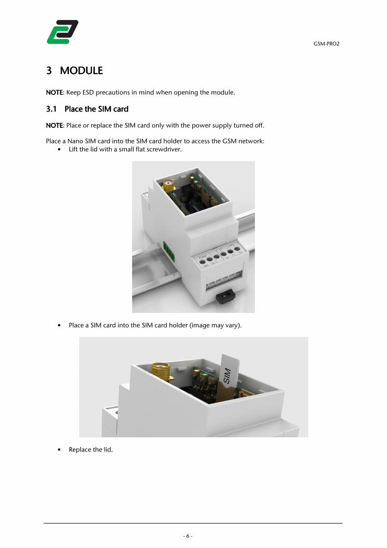
NOTENOTENOTENOTE: Place or replace the SIM card only with the power supply turned off. Place a Nano SIM card into the SIM card holder to access the GSM network:
• Lift the lid with a small flat screwdriver.
• Place a SIM card into the SIM card holder (image may vary).
• Replace the lid.
GSM-PRO2
- 7 -
3.23.23.23.2 Connect the antennaConnect the antennaConnect the antennaConnect the antenna
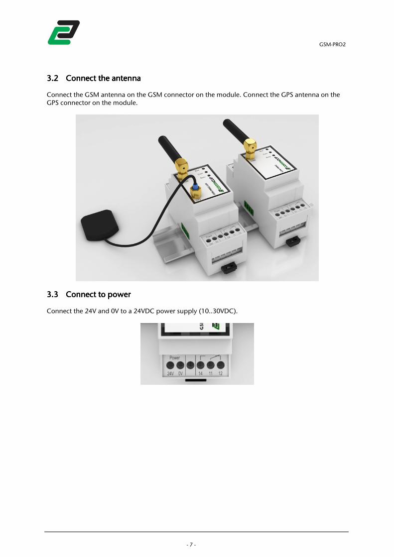
Connect the GSM antenna on the GSM connector on the module. Connect the GPS antenna on the GPS connector on the module.
3.33.33.33.3 Connect to powerConnect to powerConnect to powerConnect to power
Connect the 24V and 0V to a 24VDC power supply (10..30VDC).
GSM-PRO2
- 8 -
3.43.43.43.4 CCCCoooonnect to PCnnect to PCnnect to PCnnect to PC
With the lid removed, connect a USB cable to the micro USB socket on the module, and the other end to a USB port on a PC. NOTENOTENOTENOTE: Make sure to install the interface software and drivers before connecting the module to a PC.
3.53.53.53.5 LED descriptionLED descriptionLED descriptionLED description
3.5.13.5.13.5.13.5.1 Module status indicationModule status indicationModule status indicationModule status indication
After connecting the power it takes about 10 seconds before the first Led activates. The Led ‘Run’ indicates module activity:
• Flash = starting-up (takes about 90 seconds)
• ON = ready for use (blinks every 10 seconds)
• OFF = no power The Led ‘Com’ indicates network activity:
• green ON = connected to GSM network
• green Flash = roaming GSM network
• green OFF = not connected to GSM network
• red ON = error (see diagnostics) The Led ‘Busy’ indicates module activity:
• ON = module currently busy After data transfers between the PC and the module, the module performs a reset.
GSM-PRO2
- 9 -
4444 CONFIGURATIONCONFIGURATIONCONFIGURATIONCONFIGURATION
4.14.14.14.1 Connect to the Connect to the Connect to the Connect to the GSMGSMGSMGSM----PRO2PRO2PRO2PRO2
Connect 24VDC to the module and connect a USB cable between the GSM-PRO2 and a PC USB port. Wait for the module to start up and run the GSM-PRO2 interface software. NOTENOTENOTENOTE: module start up takes about 90 seconds, after connecting to power it takes about 10 seconds before the first Led activates. On start up the configuration software searches all available COM ports for an available GSM-PRO2. When found, the software downloads the diagnostic data and prompts to download the settings from the device. If chosen yes, the user interface will be automatically updated. If the module is found the text ‘connected to module’ at the upper left side will appear.
GSM-PRO2
- 10 -
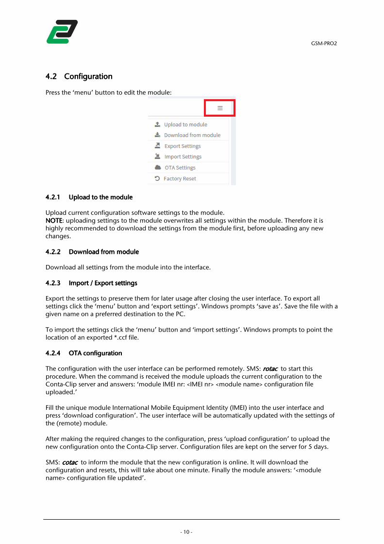
4.24.24.24.2 ConfigurationConfigurationConfigurationConfiguration
Press the ‘menu’ button to edit the module:
4.2.14.2.14.2.14.2.1 Upload to the moduleUpload to the moduleUpload to the moduleUpload to the module
Upload current configuration software settings to the module. NOTENOTENOTENOTE: uploading settings to the module overwrites all settings within the module. Therefore it is highly recommended to download the settings from the module first, before uploading any new changes. 4.2.24.2.24.2.24.2.2 Download from moduleDownload from moduleDownload from moduleDownload from module
Download all settings from the module into the interface. 4.2.34.2.34.2.34.2.3 ImImImImport / Export settingsport / Export settingsport / Export settingsport / Export settings
Export the settings to preserve them for later usage after closing the user interface. To export all settings click the ‘menu’ button and ‘export settings’. Windows prompts ‘save as’. Save the file with a given name on a preferred destination to the PC. To import the settings click the ‘menu’ button and ‘import settings’. Windows prompts to point the location of an exported *.ccf file. 4.2.44.2.44.2.44.2.4 OTA configurationOTA configurationOTA configurationOTA configuration
The configuration with the user interface can be performed remotely. SMS: rotacrotacrotacrotac to start this procedure. When the command is received the module uploads the current configuration to the Conta-Clip server and answers: ‘module IMEI nr: <IMEI nr> <module name> configuration file uploaded.’ Fill the unique module International Mobile Equipment Identity (IMEI) into the user interface and press ‘download configuration’. The user interface will be automatically updated with the settings of the (remote) module. After making the required changes to the configuration, press ‘upload configuration’ to upload the new configuration onto the Conta-Clip server. Configuration files are kept on the server for 5 days. SMS: cotaccotaccotaccotac to inform the module that the new configuration is online. It will download the configuration and resets, this will take about one minute. Finally the module answers: ‘<module name> configuration file updated’.
GSM-PRO2
- 11 -
The configuration file can also be requested by sending: ccfccfccfccf directly followed by a valid email address (e.g. [email protected]). When ready, the module answers with a confirmation message and the configuration file is received by the email address. Download and import the file into the interface. 4.2.54.2.54.2.54.2.5 Reset module to defaultReset module to defaultReset module to defaultReset module to default
Restore all settings in the module back to factory default.
GSM-PRO2
- 12 -
4.34.34.34.3 DiagnosticsDiagnosticsDiagnosticsDiagnostics
After connecting to the module the diagnostics information is filled. This shows:
• Registered GSM network or connection errors
• Signal strength and RAT (Radio Access Technology) GPRS or 3G
• Module firmware version
• IMEI number
• Error messages: - SIM PIN code required - SIM PUK code required - No SIM card - No user selected - No network registration
To request the diagnostics by SMS send: statusstatusstatusstatus. NOTENOTENOTENOTE: This information is a snapshot of the diagnostics and not displayed real-time. Refresh the diagnostics tab by clicking the ‘module info’ text.
4.3.14.3.14.3.14.3.1 Signal qualitySignal qualitySignal qualitySignal quality
The signal quality information is defined by the Dutch Telecom Agency according to GSM network regulations. The full list is shown in the appendix. To request the signal strength /and quality by SMS send: csqcsqcsqcsq.
GSM-PRO2
- 13 -
4.44.44.44.4 ContactsContactsContactsContacts
The interface software has a contacts list to store all your contacts for further usage. All actions in the contacts list will auto save on completion. 4.4.14.4.14.4.14.4.1 AddAddAddAdd/delete/delete/delete/delete contactscontactscontactscontacts
To add a contact to the contacts click on the add button and fill in the name and phone number or email address.
NOTENOTENOTENOTE: The phone number must be preceded by the international access code E.g.:
• UK +44
• Germany +49
• France +33
• Netherlands +31
• Italy +39
• Spain +34
• Poland +48
• Portugal +351 To delete a contact click the ‘delete’ button behind the contact.
Import / Import / Import / Import / Export Export Export Export contactscontactscontactscontacts
The contacts can be exported for usage on another PC that has the interface software installed. To export the contacts click the ‘contacts menu’ button and ‘export contacts’. Windows prompts ‘save as’. Save the file with a given name on a preferred destination to the PC. To import the contacts click the ‘contacts’ button and ‘import contacts’. Windows prompts to point the location of an exported *.cpf file.
GSM-PRO2
- 14 -
5555 SETTINGSSETTINGSSETTINGSSETTINGS
5.15.15.15.1 Main settingsMain settingsMain settingsMain settings
The main functions of the module are configured in the ‘settings’ tab:
• Module name
• Module Phone Number
• SIM pin number, this is the pin number to access the SIM card.
• Admin user. The admin user has full access to the module and receives no general messages.
5.25.25.25.2 Mobile DataMobile DataMobile DataMobile Data
Mark this checkbox if a data connection is required. NOTENOTENOTENOTE: Activating mobile internet can cause unexpected costs. Contact your provider for an appropriate subscription or prepaid card. If the internet connection is required but not allowed after configuration send an SMS: APN,<APN APN,<APN APN,<APN APN,<APN name>,<APN username>,<APN password>name>,<APN username>,<APN password>name>,<APN username>,<APN password>name>,<APN username>,<APN password> The module establishes an internet connection upon next restart. The module can now be upgraded or configured over the air. If the internet connection has to maintain after restart, this can be configured remotely.
5.35.35.35.3 RoamingRoamingRoamingRoaming
If roaming is disabled the module blocks SMS and data connections when registered to a foreign GSM network. NOTENOTENOTENOTE: contact your GSM service provider for roaming rates to avoid unexpected high billing.
5.45.45.45.4 AppAppAppApp
Mark the checkbox to synchronize your GSM-PRO2’s events and IO status so it can be read and controlled by an Apple iOS, Windows or Android App.
5.55.55.55.5 APN settingsAPN settingsAPN settingsAPN settings
To register to a GPRS connection, enter the APN (Access Point Name) settings of your GSM service provider. If these settings are unknown to you, request them at your provider. Remotely check the GSM data connection by sending: cdccdccdccdc. The module answers with the status of the connection.
5.65.65.65.6 SMTPSMTPSMTPSMTP
Enter the SMTP (Simple Mail Transfer Protocol) settings for outgoing email. The SMTP is used to send email via outgoing mail server. Contact your Internet Service Provider or Webhost for further information about your SMTP settings. NOTENOTENOTENOTE: Some free mail providers like Gmail or Outlook require 2 way authentication and they do not accept unknown m2m devices to access their SMTP server.
GSM-PRO2
- 15 -
6666 GENERAL MESSAGESGENERAL MESSAGESGENERAL MESSAGESGENERAL MESSAGES
6.1.16.1.16.1.16.1.1 Periodical messagePeriodical messagePeriodical messagePeriodical message
The GSM-PRO2 can send a periodical message on a user defined time:
• Daily, set the time
• Weekly, set the day and time
• Monthly, set the day of the month and time This message can be supplemented with the actual status of all IOs. 6.1.26.1.26.1.26.1.2 Power cycle messagePower cycle messagePower cycle messagePower cycle message
The GSM-PRO2 can send a message on every module start up, so the users are aware of a power recovery. 6.1.36.1.36.1.36.1.3 Power down messagePower down messagePower down messagePower down message
On power loss the module holds enough capacity to send SMS messages to the first 5 selected GSM users. The GSM-PRO2 detects a power down when the power < 8V and returns when the power >10V. NOTENOTENOTENOTE: The module tries to send the message to all defined users in the ‘General Message’ tab with the guarantee of the first 5 selected users. 6.1.46.1.46.1.46.1.4 GSM connection loss messageGSM connection loss messageGSM connection loss messageGSM connection loss message
The module buffers a message upon GSM connection loss and sends this along with a GSM recovered message once the connection is recovered. 6.1.56.1.56.1.56.1.5 RecipientsRecipientsRecipientsRecipients
The active users are those who receive the auto messages. 6.1.66.1.66.1.66.1.6 Additional messagesAdditional messagesAdditional messagesAdditional messages
The following automatic generated messages are send to the users in the general messages tab:
• Log full 90%
• Log full 100%
• DO counter full
• DI counter full
• Extension stopped responding
• Extension not responding on startup
• Wrong extension configured
GSM-PRO2
- 16 -
7777 LOGLOGLOGLOG
7.17.17.17.1 LogLogLogLog
The GSM-PRO2 can keep log files with a maximum size of 100kB. Select an email address in the Log tab to auto send a full log and continue logging. When no email is selected and a log is 90% full the module sends a warning message to the users in the general message tab. When the log is 100% full the module sends another warning message and then it stops logging until downloaded and erased. Each log can be viewed and erased while connected to the PC by clicking the button or remote by sending a command. 7.1.17.1.17.1.17.1.1 Event logEvent logEvent logEvent log
When this log is enabled the GSM-PRO2 logs the following events:
• Reached threshold limits on the AI inputs
• Rising and falling flank on the digital inputs (DI)
• Received messages
• Sent messages
• Data transmissions
• OTA updates
• Extension changes When connected, view this log by clicking ‘download event log’. View remote by sending: evlogevlogevlogevlog directly followed by a valid email address (e.g. [email protected]). When ready, the module answers with a confirmation message and the event log is received at the email address. When connected erase the event log by clicking ‘erase event log’. Erase remote by sending: evclrevclrevclrevclr. The module answers with a confirmation message. 7.1.27.1.27.1.27.1.2 AI logAI logAI logAI log
Choose the interval for the AI log:
• 10 min (5 days)
• 15 min (7.5 days)
• 20 min (10 days)
• 30 min (15 days)
• 45 min (22.5 days)
• 60 min (30 days) The log duration in days is based on logging 1 AI. When connected, view this log by clicking ‘download AI log’. View remote by sending: aiaiaiailoglogloglog directly followed by a valid email address (e.g. [email protected]). When ready the module answers with a confirmation message and the AI log is received by the email address. When connected, erase the event log by clicking ‘erase AI log’. Erase remote by sending: aiclraiclraiclraiclr . The module answers with a confirmation message.
GSM-PRO2
- 17 -
8888 SOFTWARE UPDATESSOFTWARE UPDATESSOFTWARE UPDATESSOFTWARE UPDATES
8.18.18.18.1 UpdateUpdateUpdateUpdate
The GSM-PRO2 can perform firmware updates remote(OTA) or when connected by USB to a PC. OOOOver TTTThe AAAAir (OTA) covers remote actions where the data is transmitted over mobile data. 8.1.18.1.18.1.18.1.1 ManManManManual firmware updatesual firmware updatesual firmware updatesual firmware updates
Download the latest firmware at: http://www.conta-clip.com/en/service/ Access the ‘advanced settings’ by clicking the ‘gearbox’ icon. After downloading, unzip the complete folder to a location on your PC. Click the firmware update button and the software prompts to the location of the firmware. Locate the unzipped folder and select the GSM-PRO2.jar file. The firmware update takes about 2 minutes. After the update the module restarts itself. NOTENOTENOTENOTE: do NOT disconnect the module or turn off the power supply during this operation. 8.1.28.1.28.1.28.1.2 OTA firmware updateOTA firmware updateOTA firmware updateOTA firmware update
To remotely update the firmware SMS: fotapfotapfotapfotap. The GSM-PRO2 downloads the online firmware, installs it and restarts. When a firmware update is succeeded the module sends a confirmation to the sender. To check the modules current firmware version send: fwvfwvfwvfwv. The module answers <module name> firmware version: <version number>. To check if there is a newer firmware version available send: cupcupcupcupdddd. The module answers <module name> (No) update found. Online <firmware version> local: <firmware version>.
GSM-PRO2
- 18 -
9999 I/OI/OI/OI/O CONFIGURATION AND MECONFIGURATION AND MECONFIGURATION AND MECONFIGURATION AND MESSAGINGSSAGINGSSAGINGSSAGING
The module responds to read and write commands. Commands are preceded by an ‘r’ for read and ‘w’ for write actions. All SMS commands are NOT case sensitive.
9.19.19.19.1 Digital OutputDigital OutputDigital OutputDigital Output
9.1.19.1.19.1.19.1.1 ConfigurationConfigurationConfigurationConfiguration
The GSM-PRO2 has 1 CO output. The following items can be configured with the software:
• Name
• After setting the digital output the module sends a confirmation message according to the configured rise or fall message. This message is sent only to the sender of the message.
• Send only the user defined text, this sends only the text defined in the message box, no module name, IO name and timestamp.
• Define your own instructions to control the output.
• Activate or toggle the output when starting a phone call with the module.
• Link DO to DI
• Activate when GSM connection lost, deactivate when GSM connection returns.
• Preserve or deactivate the status on restart or power cycle.
9.1.29.1.29.1.29.1.2 Select Select Select Select usersusersusersusers
The recipients have access to the associated digital output. NOTENOTENOTENOTE: Selected DO users do not have any rights to send other commands to the module other than addressed to the defined output. 9.1.39.1.39.1.39.1.3 MessagingMessagingMessagingMessaging
It is possible to send self-made instructions or use the pre-defined instructions for the output. With these instructions the output can be activated, deactivated and activated for a given period of time (one-shot).
9.1.3.19.1.3.19.1.3.19.1.3.1 Number IDNumber IDNumber IDNumber ID
The number ID for setting the digital output can be disabled. When disabled the output responds on both SMS and incoming calls from everyone. NOTENOTENOTENOTE: keep safety precautions in mind when disabling this function together with the ring function due to unwanted incoming calls.
9.1.3.29.1.3.29.1.3.29.1.3.2 User defined instructionsUser defined instructionsUser defined instructionsUser defined instructions
Use a self-made instruction to control the output. E.g. you may want to use the instruction pumpon to activate the output, and pumpoff to deactivate.
9.1.3.39.1.3.39.1.3.39.1.3.3 Change theChange theChange theChange the digital outputdigital outputdigital outputdigital output statusstatusstatusstatus
To set the digital output (DO) send the following default message: wdowdowdowdox, where x is the state. E.g. when you send wdowdowdowdo1, DO is set to 1. If set, the module sends a confirmation message: ‘status DO=x‘. If the output state is already in the state, the text: ‘status not changed’ is added to the answer.
GSM-PRO2
- 19 -
9.1.49.1.49.1.49.1.4 Using the oneUsing the oneUsing the oneUsing the one----shot functionshot functionshot functionshot function
The digital outputs can be set for a given time from 1 to 10 hours. When this command is received, the DO sets to 1 and after the number of seconds the DO falls back to 0. The one shot function is called by selecting the DO followed by a ‘t’ for time and the time in seconds. E.g. when you send wdowdowdowdot10t10t10t10 the DO is set for 10 seconds. The one-shot function sends two answers, one at the start and one at the end of the sequence. NOTENOTENOTENOTE: see user defined functions to define own instructions. 9.1.59.1.59.1.59.1.5 React React React React on RINGon RINGon RINGon RING
This function enables toggling the DO on a RING (phone call) command. When one of the selected users in the settings tab dials the number of the module it toggles the DOs and breaks the connection. The caller receives a SMS message with the status of the DO. When the output timer value is set the output status is set to 1 for the amount of seconds set. If the output status is already 1 this is kept for the amount of seconds and then set to 0. Clear the output timer value in the user interface to disable the timer function. 9.1.69.1.69.1.69.1.6 Link DO to DILink DO to DILink DO to DILink DO to DI
The DO can be linked to DI1. When a status change on a DI1 is detected the DO will adopt this status. The status of the DO can always be overruled by an SMS message setting the output(see above). If the output has already the same state as the linked input the output will not change. NOTENOTENOTENOTE: This function can conflict with the SMS and RING instructions. 9.1.79.1.79.1.79.1.7 ActivateActivateActivateActivate when GSM connection when GSM connection when GSM connection when GSM connection is is is is loslosloslostttt
Select to activate the output when the GSM connection is lost. The output deactivates as soon as the GSM connection is re-established. NNNNOTEOTEOTEOTE: This function can conflict with the SMS and RING instructions. 9.1.89.1.89.1.89.1.8 Preserve status on startupPreserve status on startupPreserve status on startupPreserve status on startup
Choose if the status of the output is preserved on restart or power cycle. If deselected the output will be deactivated. 9.1.99.1.99.1.99.1.9 Wiring exampleWiring exampleWiring exampleWiring example
In the following example the Do is connected as normally open.
GSM-PRO2
- 20 -
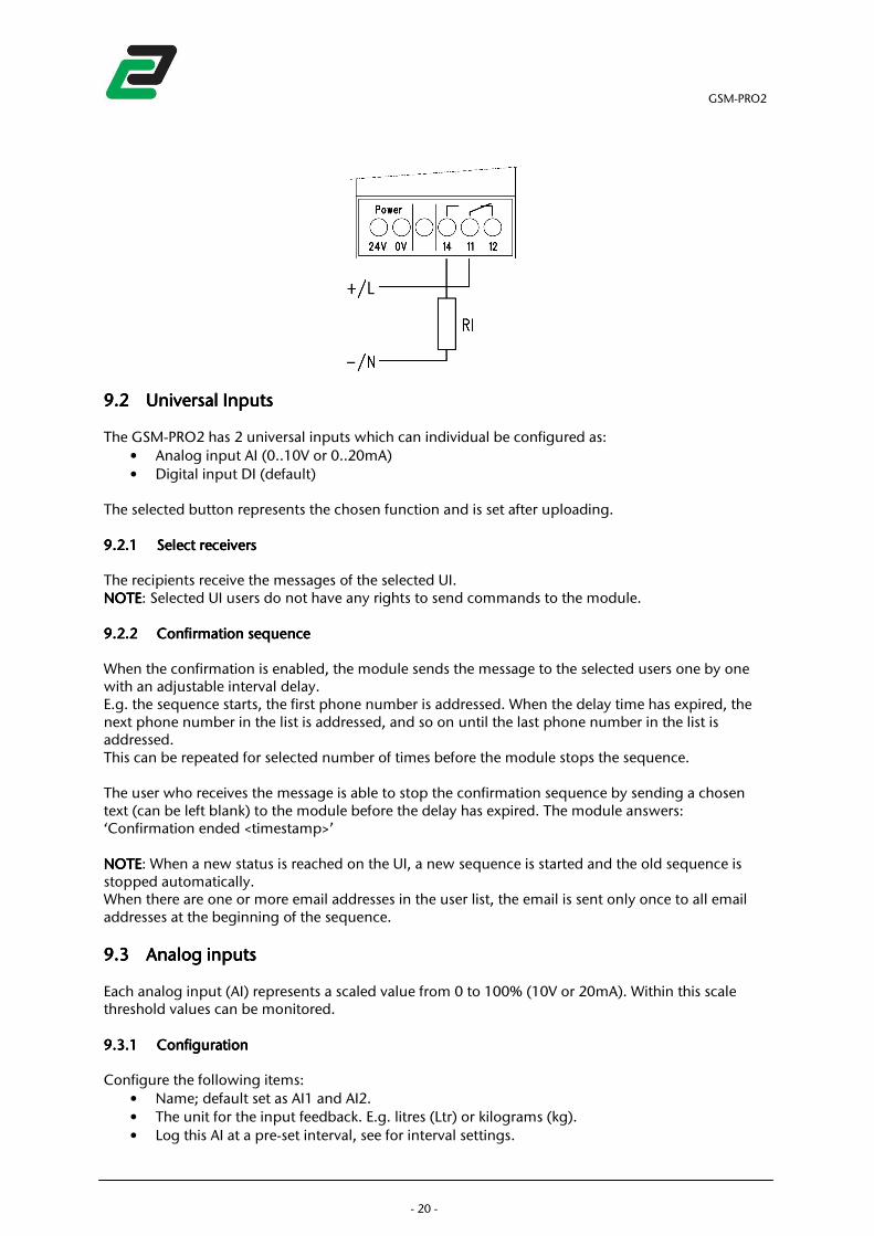
9.29.29.29.2 Universal InputUniversal InputUniversal InputUniversal Inputssss
The GSM-PRO2 has 2 universal inputs which can individual be configured as:
• Analog input AI (0..10V or 0..20mA)
• Digital input DI (default) The selected button represents the chosen function and is set after uploading. 9.2.19.2.19.2.19.2.1 Select receiversSelect receiversSelect receiversSelect receivers
The recipients receive the messages of the selected UI. NOTENOTENOTENOTE: Selected UI users do not have any rights to send commands to the module. 9.2.29.2.29.2.29.2.2 Confirmation sequenceConfirmation sequenceConfirmation sequenceConfirmation sequence
When the confirmation is enabled, the module sends the message to the selected users one by one with an adjustable interval delay. E.g. the sequence starts, the first phone number is addressed. When the delay time has expired, the next phone number in the list is addressed, and so on until the last phone number in the list is addressed. This can be repeated for selected number of times before the module stops the sequence. The user who receives the message is able to stop the confirmation sequence by sending a chosen text (can be left blank) to the module before the delay has expired. The module answers: ‘Confirmation ended <timestamp>’ NOTENOTENOTENOTE: When a new status is reached on the UI, a new sequence is started and the old sequence is stopped automatically. When there are one or more email addresses in the user list, the email is sent only once to all email addresses at the beginning of the sequence.
9.39.39.39.3 Analog inputAnalog inputAnalog inputAnalog inputssss
Each analog input (AI) represents a scaled value from 0 to 100% (10V or 20mA). Within this scale threshold values can be monitored. 9.3.19.3.19.3.19.3.1 ConfigurationConfigurationConfigurationConfiguration
Configure the following items:
• Name; default set as AI1 and AI2.
• The unit for the input feedback. E.g. litres (Ltr) or kilograms (kg).
• Log this AI at a pre-set interval, see for interval settings.
GSM-PRO2
- 21 -
• The min. value represents the scaled value for 0V
• The max. value represents the scaled value for 10V or 20mA
• Lower limit threshold
• Upper limit threshold
• Minimal change (hysteresis)
• Send only the user defined text, this sends only the text defined in the message box, no module name, IO name and timestamp.
• The Analog Inputs can generate messages including value and unit when: - The upper limit + hysteresis is reached - The lower limit – hysteresis is reached - The status recovers between the upper and lower limit +/- hysteresis
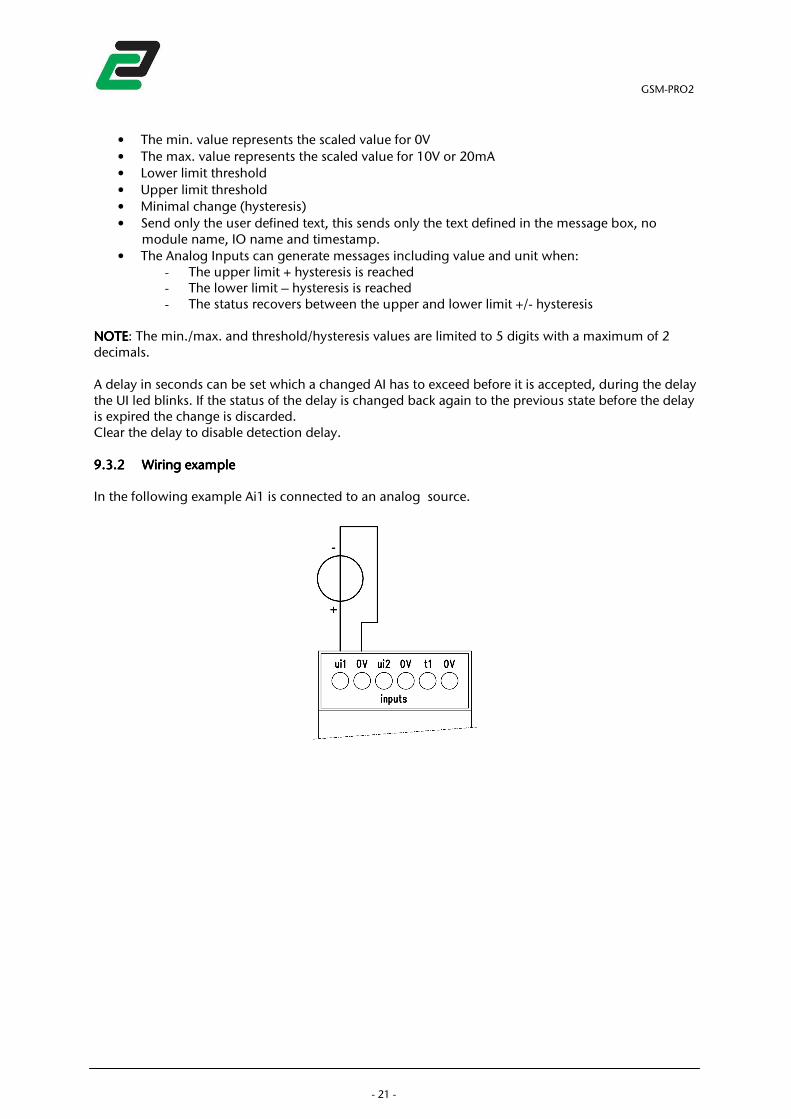
NOTENOTENOTENOTE: The min./max. and threshold/hysteresis values are limited to 5 digits with a maximum of 2 decimals. A delay in seconds can be set which a changed AI has to exceed before it is accepted, during the delay the UI led blinks. If the status of the delay is changed back again to the previous state before the delay is expired the change is discarded. Clear the delay to disable detection delay. 9.3.29.3.29.3.29.3.2 Wiring exampleWiring exampleWiring exampleWiring example
In the following example Ai1 is connected to an analog source.
GSM-PRO2
- 22 -
9.49.49.49.4 Digital InputDigital InputDigital InputDigital Inputssss
9.4.19.4.19.4.19.4.1 ConfigurationConfigurationConfigurationConfiguration
Configure the following items:
• Name; default set as DI1 and DI2.
• The Digital Inputs can generate messages when: - A rising flank is detected: the status changes from 0 to 1 - A falling flank is detected: the status changes from 1 to 0
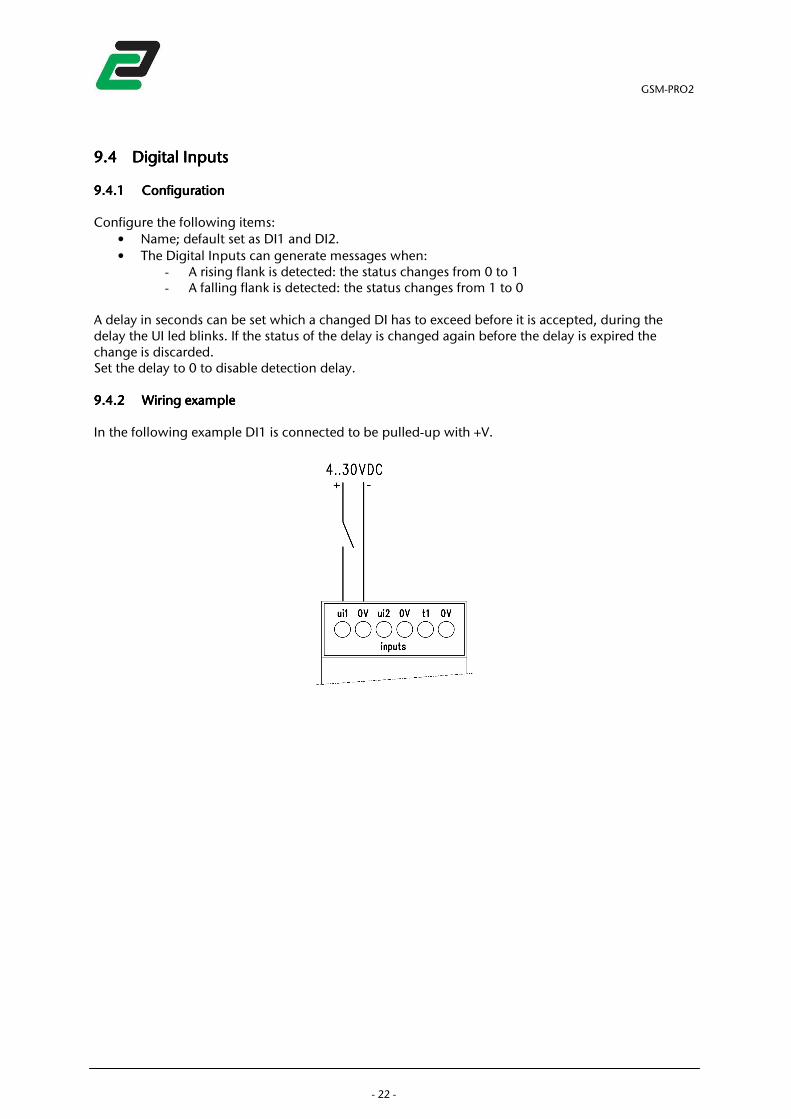
A delay in seconds can be set which a changed DI has to exceed before it is accepted, during the delay the UI led blinks. If the status of the delay is changed again before the delay is expired the change is discarded. Set the delay to 0 to disable detection delay. 9.4.29.4.29.4.29.4.2 Wiring exampleWiring exampleWiring exampleWiring example
In the following example DI1 is connected to be pulled-up with +V.
GSM-PRO2
- 23 -
9.59.59.59.5 Read all IO statusesRead all IO statusesRead all IO statusesRead all IO statuses
To retrieve the status of all IOs send: rallrallrallrall. The module answers: <Module name> IO status: DO=x UI1=xxx UI2=xxx Followed by the statuses of all extension units. Where UI is replaced by the chosen input type: AI or DI. To send the full IO status to an email address send: rall<email>rall<email>rall<email>rall<email>.
9.69.69.69.6 Link multiple Link multiple Link multiple Link multiple GSMGSMGSMGSM----PRO2PRO2PRO2PRO2’s’s’s’s
It’s possible to link multiple GSM-PRO2 units by SMS. By selecting the ‘send only user defined text’ in the IO configuration it’s possible to send the pre-defined messages to other modules. For example: digital input 2 sends WDO1 on a rising flank to a second unit. This unit receives the message, set’s the digital. On the falling flank the first unit sends WDO0 to deactivate the digital output on the second unit. It is also possible to send an SMS to itself and activate digital outputs on reaction to digital inputs. NOTENOTENOTENOTE: The digital outputs cannot parse any messages. They only respond to their sender.
9.79.79.79.7 IO operating hours counterIO operating hours counterIO operating hours counterIO operating hours counter
The IO operating hours counter sums the total time the IO is in HI state. The counter can be turned on/off each individual digital in- and output. The counted value can be added to the periodical message and ‘RALL’. Counters are limited to 17500 hours (+/- 2 years). NOTENOTENOTENOTE: make sure to keep all IO’s in LO state when configuring the counters due to faults in starting time. 9.7.19.7.19.7.19.7.1 Request digital output counterRequest digital output counterRequest digital output counterRequest digital output counter
To retrieve the counter value of an individual digital output, send: timedotimedotimedotimedo. The module answers: ‘Do ON for x,xx hours’. 9.7.29.7.29.7.29.7.2 ReqReqReqRequest digital input counterest digital input counterest digital input counterest digital input counter
To retrieve the counter value of an individual digital input, send: timeditimeditimeditimedin, where n is the number of the requested digital input. The module answers: ‘Din ON for x,xx hours’. To retrieve the counter value of all digital inputs send: timedi0.timedi0.timedi0.timedi0. The module answers: ‘Di1 was ON for x,xx hours, Di2 was ON for x,xx hours’. 9.7.39.7.39.7.39.7.3 Reset digital output counterReset digital output counterReset digital output counterReset digital output counter
To reset the counter value of the digital output, send: clrtimedoclrtimedoclrtimedoclrtimedo. The module answers: ‘erasing counter Do’.

GSM-PRO2
- 24 -
9.7.49.7.49.7.49.7.4 Reset digital input Reset digital input Reset digital input Reset digital input countercountercountercounter
To reset the counter value of an individual digital input, send: clrtimediclrtimediclrtimediclrtimedin, where n is the number of the requested digital input. The module answers: ‘erasing counter Din’. To reset the counter values of all digital inputs, send: clrtimedi0clrtimedi0clrtimedi0clrtimedi0. The module answers: ‘erasing counter Di1, erasing counter Di2’.
GSM-PRO2
- 25 -
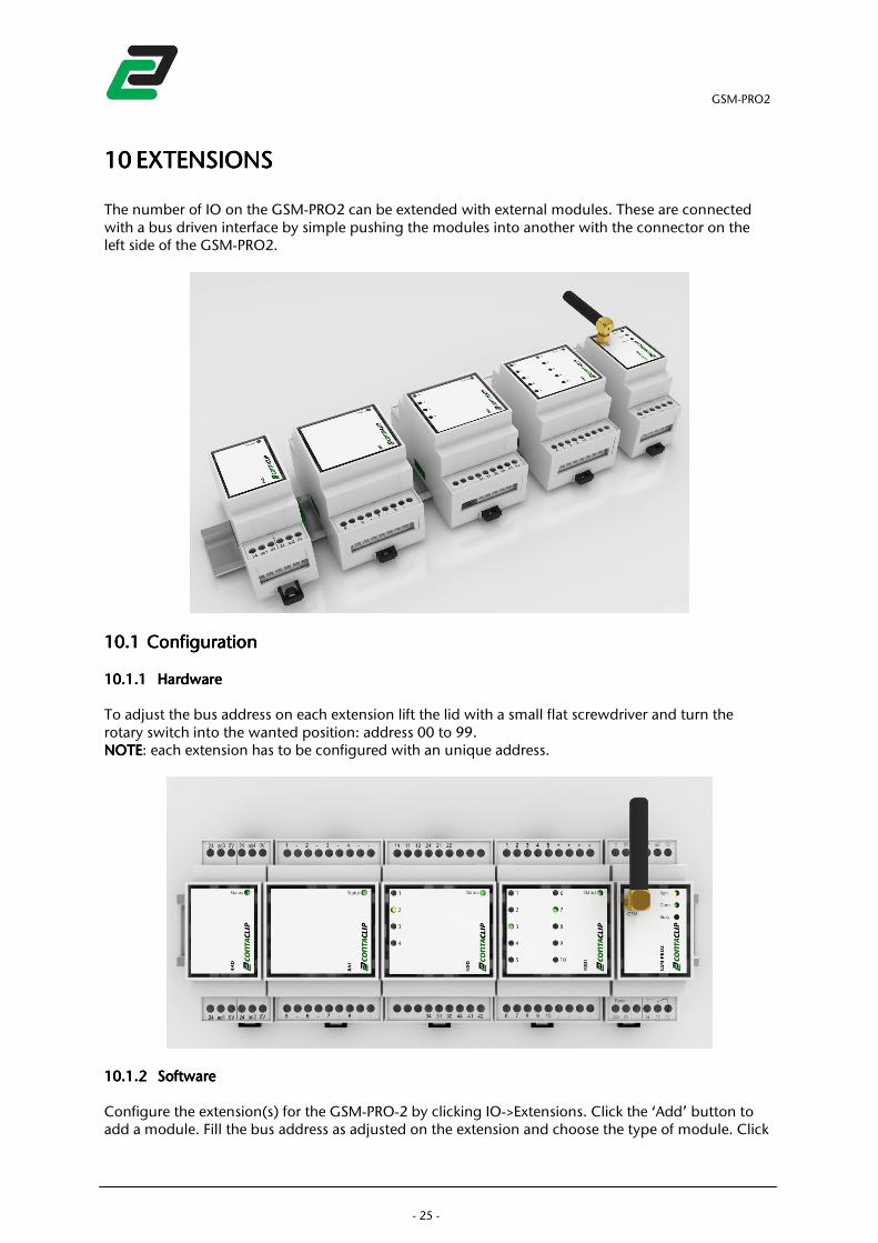
10101010 EXTENSIONSEXTENSIONSEXTENSIONSEXTENSIONS
The number of IO on the GSM-PRO2 can be extended with external modules. These are connected with a bus driven interface by simple pushing the modules into another with the connector on the left side of the GSM-PRO2.
10.110.110.110.1 ConfigurationConfigurationConfigurationConfiguration
10.1.110.1.110.1.110.1.1 HardwareHardwareHardwareHardware
To adjust the bus address on each extension lift the lid with a small flat screwdriver and turn the rotary switch into the wanted position: address 00 to 99. NOTENOTENOTENOTE: each extension has to be configured with an unique address.
10.1.210.1.210.1.210.1.2 SoftwareSoftwareSoftwareSoftware
Configure the extension(s) for the GSM-PRO-2 by clicking IO->Extensions. Click the ‘Add’ button to add a module. Fill the bus address as adjusted on the extension and choose the type of module. Click
GSM-PRO2
- 26 -
‘Add’ and the module appears in the list. Repeat this step for the number of extensions connected to the GSM-PRO2. Each added module can be configured with a module name and up to 10 users who have access to the module in case of outputs, or receive messages in case of inputs. NOTENOTENOTENOTE: Failure on Extensions are sent to the users in the general message tab.
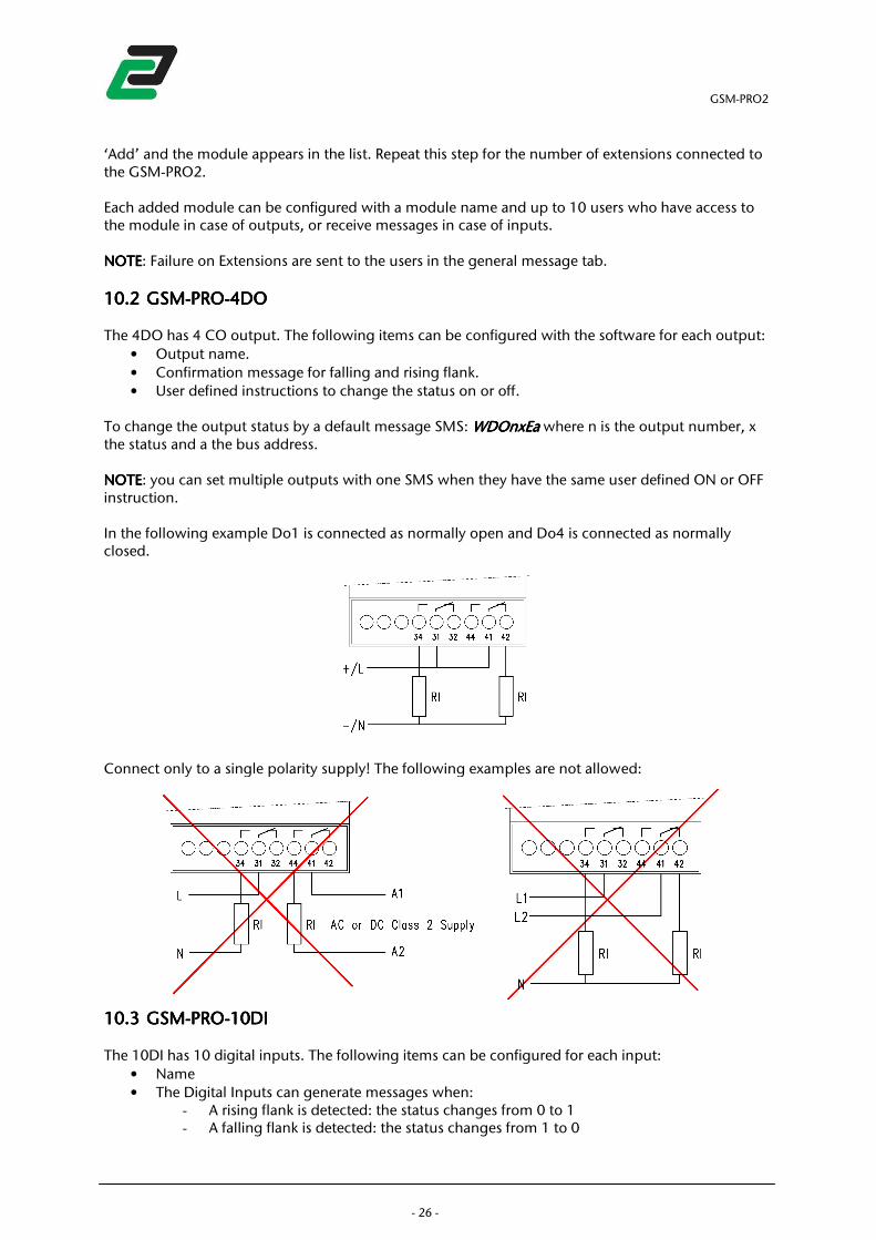
10.210.210.210.2 GSMGSMGSMGSM----PROPROPROPRO----4DO4DO4DO4DO
The 4DO has 4 CO output. The following items can be configured with the software for each output:
• Output name.
• Confirmation message for falling and rising flank.
• User defined instructions to change the status on or off. To change the output status by a default message SMS: WDOnxEaWDOnxEaWDOnxEaWDOnxEa where n is the output number, x the status and a the bus address. NOTENOTENOTENOTE: you can set multiple outputs with one SMS when they have the same user defined ON or OFF instruction. In the following example Do1 is connected as normally open and Do4 is connected as normally closed.
Connect only to a single polarity supply! The following examples are not allowed:
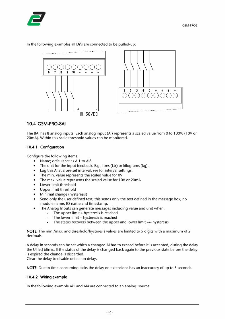
10.310.310.310.3 GSMGSMGSMGSM----PROPROPROPRO----10DI10DI10DI10DI
The 10DI has 10 digital inputs. The following items can be configured for each input:
• Name
• The Digital Inputs can generate messages when: - A rising flank is detected: the status changes from 0 to 1 - A falling flank is detected: the status changes from 1 to 0
GSM-PRO2
- 27 -
In the following examples all Di’s are connected to be pulled-up:
10.410.410.410.4 GSMGSMGSMGSM----PROPROPROPRO----8AI8AI8AI8AI
The 8AI has 8 analog inputs. Each analog input (AI) represents a scaled value from 0 to 100% (10V or 20mA). Within this scale threshold values can be monitored. 10.4.110.4.110.4.110.4.1 ConfigurationConfigurationConfigurationConfiguration
Configure the following items:
• Name; default set as AI1 to AI8.
• The unit for the input feedback. E.g. litres (Ltr) or kilograms (kg).
• Log this AI at a pre-set interval, see for interval settings.
• The min. value represents the scaled value for 0V
• The max. value represents the scaled value for 10V or 20mA
• Lower limit threshold
• Upper limit threshold
• Minimal change (hysteresis)
• Send only the user defined text, this sends only the text defined in the message box, no module name, IO name and timestamp.
• The Analog Inputs can generate messages including value and unit when: - The upper limit + hysteresis is reached - The lower limit – hysteresis is reached - The status recovers between the upper and lower limit +/- hysteresis
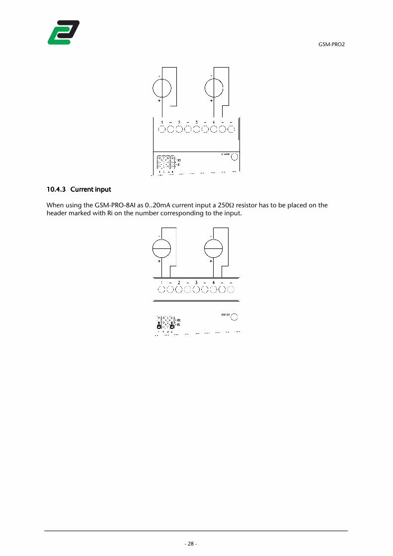
NOTENOTENOTENOTE: The min./max. and threshold/hysteresis values are limited to 5 digits with a maximum of 2 decimals. A delay in seconds can be set which a changed AI has to exceed before it is accepted, during the delay the UI led blinks. If the status of the delay is changed back again to the previous state before the delay is expired the change is discarded. Clear the delay to disable detection delay. NOTENOTENOTENOTE: Due to time consuming tasks the delay on extensions has an inaccuracy of up to 5 seconds. 10.4.210.4.210.4.210.4.2 Wiring exampleWiring exampleWiring exampleWiring example
In the following example Ai1 and AI4 are connected to an analog source.
GSM-PRO2
- 28 -
10.4.310.4.310.4.310.4.3 Current inputCurrent inputCurrent inputCurrent input
When using the GSM-PRO-8AI as 0..20mA current input a 250Ω resistor has to be placed on the header marked with Ri on the number corresponding to the input.
GSM-PRO2
- 29 -
11111111 OTHER MESSAGESOTHER MESSAGESOTHER MESSAGESOTHER MESSAGES
11.111.111.111.1 Module resetModule resetModule resetModule reset
Reset with the following command: wresetwresetwresetwreset. This performs a full module reset. The module answers with the power cycle message if set.
11.211.211.211.2 Stop messagingStop messagingStop messagingStop messaging
The command: mesmesmesmesoff off off off will stop the module from sending any more messages. The module answers: ‘messaging turned off’. To turn back on the messaging send: mesmesmesmesonononon. The module answers: ‘messaging turned on’.
11.311.311.311.3 Show all SMS commandsShow all SMS commandsShow all SMS commandsShow all SMS commands
Send helphelphelphelp to receive a list with all commands. See chapter 10 for an overview.
11.411.411.411.4 LocationLocationLocationLocation
When a module is equipped with GPS send an SMS: locationlocationlocationlocation to receive a link to Google maps with a pinpoint to the module.
GSM-PRO2
- 30 -
12121212 ADDITIONAL ADDITIONAL ADDITIONAL ADDITIONAL SOFTWARESOFTWARESOFTWARESOFTWARE
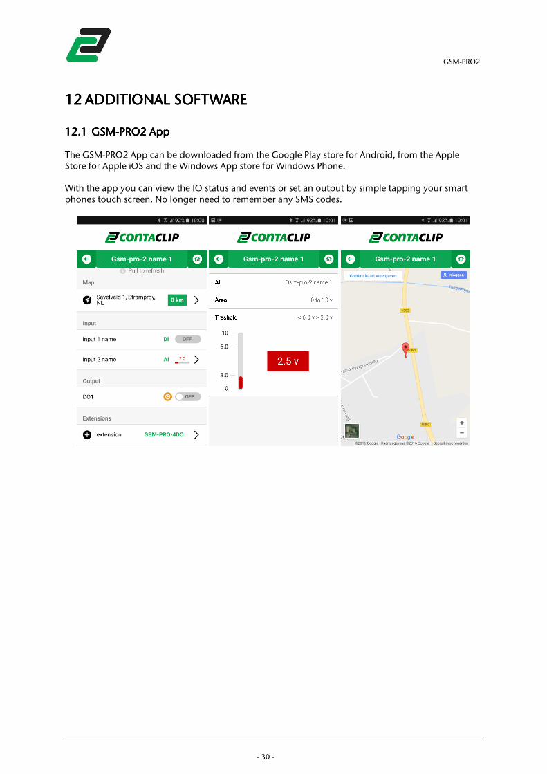
12.112.112.112.1 GSMGSMGSMGSM----PRO2PRO2PRO2PRO2 AppAppAppApp
The GSM-PRO2 App can be downloaded from the Google Play store for Android, from the Apple Store for Apple iOS and the Windows App store for Windows Phone. With the app you can view the IO status and events or set an output by simple tapping your smart phones touch screen. No longer need to remember any SMS codes.
GSM-PRO2
- 31 -
13131313 TROUBLESHOOTINGTROUBLESHOOTINGTROUBLESHOOTINGTROUBLESHOOTING
13.113.113.113.1 Cannot connect to the PCCannot connect to the PCCannot connect to the PCCannot connect to the PC, no module found, no module found, no module found, no module found
• Re-connect the USB cable from the PC.
• Reboot the PC (after driver installation).
• Start the program as administrator, right click->Run as administrator.
• Try a different USB port, remove any hubs or extension cables.
13.213.213.213.2 No connection to GSM networkNo connection to GSM networkNo connection to GSM networkNo connection to GSM network
• Make sure the SIM card is placed correctly.
• Check the diagnostics tab for error messages, PUK or PIN required.
• Check the signal strength.
13.313.313.313.3 The module doesn’t send any messagesThe module doesn’t send any messagesThe module doesn’t send any messagesThe module doesn’t send any messages
• Is the used IO proper set.
• Make sure the SIM card is placed correct.
• Does the prepaid card holds enough credit.
• Check your email spam/unwanted box.
13.413.413.413.4 The module doesn’t The module doesn’t The module doesn’t The module doesn’t startstartstartstart
• Disconnect from power, wait 5 minutes and reconnect to power.
13.513.513.513.5 DiagnosisDiagnosisDiagnosisDiagnosis
For additional troubleshooting, the activities in the module can be monitored with the diagnosis window. To open this right click the GSM-PRO2 icon in the taskbar and select ‘open Diagnostics’.
GSM-PRO2
- 32 -
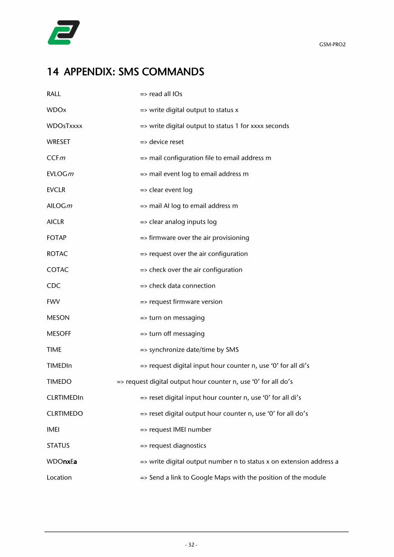
14141414 APPENDIXAPPENDIXAPPENDIXAPPENDIX: : : : SMS COMMANDSSMS COMMANDSSMS COMMANDSSMS COMMANDS
RALL => read all IOs WDOx => write digital output to status x WDOsTxxxx => write digital output to status 1 for xxxx seconds WRESET => device reset CCFm => mail configuration file to email address m EVLOGm => mail event log to email address m EVCLR => clear event log AILOGm => mail AI log to email address m AICLR => clear analog inputs log FOTAP => firmware over the air provisioning ROTAC => request over the air configuration COTAC => check over the air configuration CDC => check data connection FWV => request firmware version MESON => turn on messaging MESOFF => turn off messaging TIME => synchronize date/time by SMS TIMEDIn => request digital input hour counter n, use ‘0’ for all di’s TIMEDO => request digital output hour counter n, use ‘0’ for all do’s CLRTIMEDIn => reset digital input hour counter n, use ‘0’ for all di’s CLRTIMEDO => reset digital output hour counter n, use ‘0’ for all do’s IMEI => request IMEI number STATUS => request diagnostics WDOnxnxnxnxEaaaa => write digital output number n to status x on extension address a Location => Send a link to Google Maps with the position of the module
GSM-PRO2
- 33 -
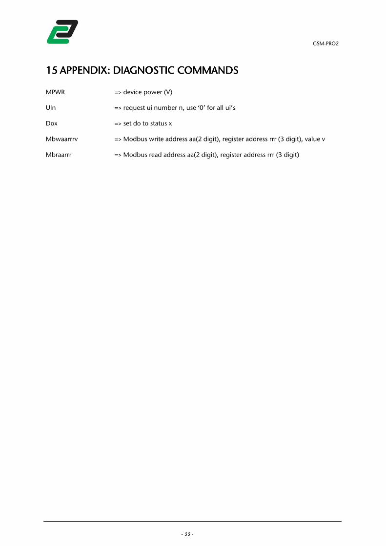
15151515 APPENDIX: DIAGNOSTICAPPENDIX: DIAGNOSTICAPPENDIX: DIAGNOSTICAPPENDIX: DIAGNOSTIC COMMANDSCOMMANDSCOMMANDSCOMMANDS
MPWR => device power (V) UIn => request ui number n, use ‘0’ for all ui’s Dox => set do to status x Mbwaarrrv => Modbus write address aa(2 digit), register address rrr (3 digit), value v Mbraarrr => Modbus read address aa(2 digit), register address rrr (3 digit)
GSM-PRO2
- 34 -
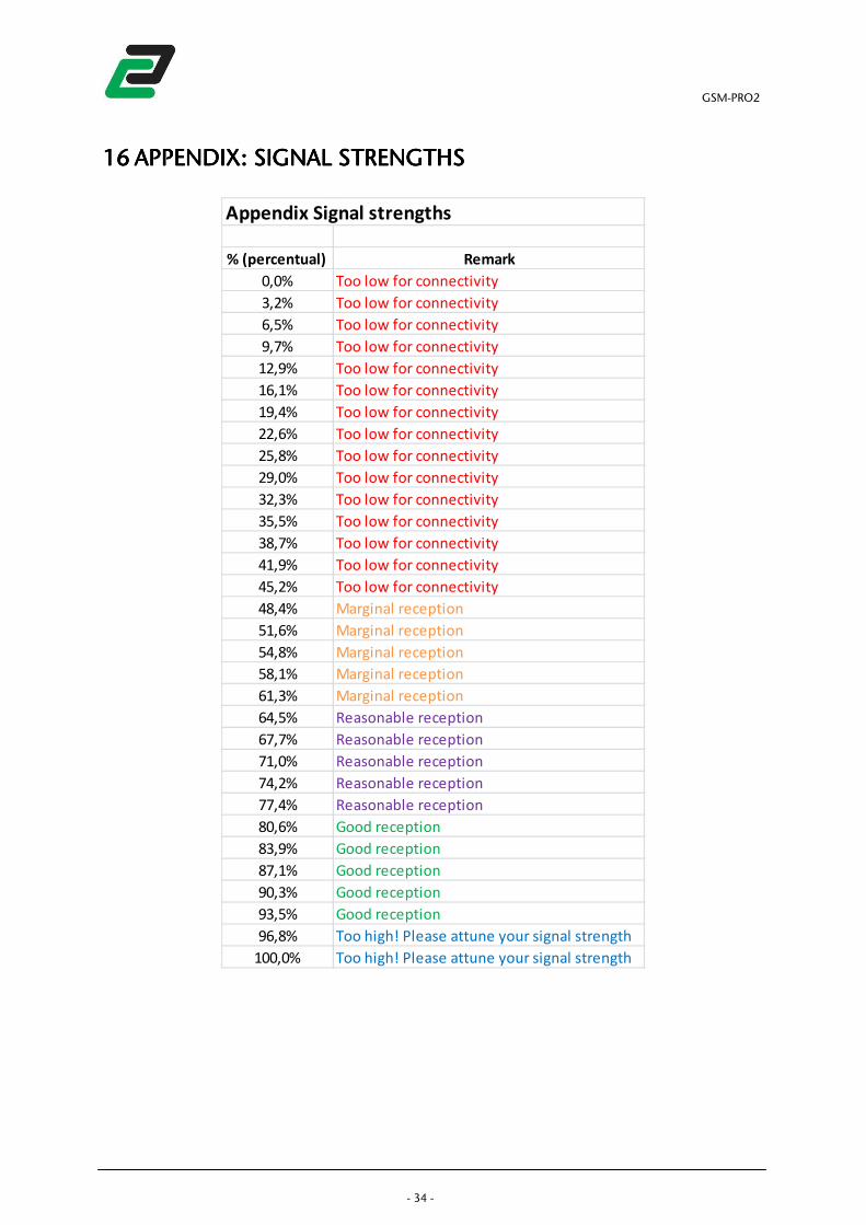
16161616 APPENDIX: SIGNAL STRAPPENDIX: SIGNAL STRAPPENDIX: SIGNAL STRAPPENDIX: SIGNAL STRENGTHSENGTHSENGTHSENGTHS
Appendix Signal strengths
% (percentual) Remark
0,0% Too low for connectivity
3,2% Too low for connectivity
6,5% Too low for connectivity
9,7% Too low for connectivity
12,9% Too low for connectivity
16,1% Too low for connectivity
19,4% Too low for connectivity
22,6% Too low for connectivity
25,8% Too low for connectivity
29,0% Too low for connectivity
32,3% Too low for connectivity
35,5% Too low for connectivity
38,7% Too low for connectivity
41,9% Too low for connectivity
45,2% Too low for connectivity
48,4% Marginal reception
51,6% Marginal reception
54,8% Marginal reception
58,1% Marginal reception
61,3% Marginal reception
64,5% Reasonable reception
67,7% Reasonable reception
71,0% Reasonable reception
74,2% Reasonable reception
77,4% Reasonable reception
80,6% Good reception
83,9% Good reception
87,1% Good reception
90,3% Good reception
93,5% Good reception
96,8% Too high! Please attune your signal strength
100,0% Too high! Please attune your signal strength