Embed Size (px)
Citation preview
GSM Easy MINIATURE GSM/GPRS COMMUNICATOR
INSTALLATION AND USER’S GUIDE
Version: 2.1
Page 2
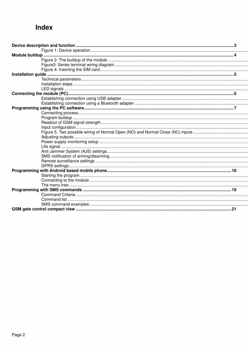
Index
Device description and function ......................................................................................................................................... 3 Figure 1: Device operation ......................................................................................................................................................
Module buildup ..................................................................................................................................................................... 4 Figure 2: The buildup of the module ................................................................................................................................Figure3: Series terminal wiring diagram ................................................................................................................................Figure 4: Inserting the SIM card ..............................................................................................................................................
Installation guide .................................................................................................................................................................. 5 Technical parameters ..............................................................................................................................................................Installation steps ................................................................................................................................................................LED signals ................................................................................................................................................................
Connecting the module (PC)................................................................................................................................................ 6 Establishing connection using USB adapter ...........................................................................................................................Establishing connection using a Bluetooth adapter ................................................................................................................
Programming using the PC software .................................................................................................................................. 7 Connecting process ................................................................................................................................................................Program buildup ................................................................................................................................................................Readout of GSM signal strength ................................................................................................................................Input configuration ................................................................................................................................................................Figure 5. Two possible wiring of Normal Open (NO) and Normal Close (NC) inputs ...........................................................Adjusting outputs ................................................................................................................................................................Power supply monitoring setup .............................................................................................................................................Life signal ..............................................................................................................................................................................Anti Jammer System (AJS) settings ................................................................................................................................SMS notification of arming/disarming ................................................................................................................................Remote surveillance settings ................................................................................................................................................GPRS settings ................................................................................................................................................................
Programming with Android based mobile phone ............................................................................................................ 18 Starting the program ..............................................................................................................................................................Connecting to the module .....................................................................................................................................................The menu tree ................................................................................................................................................................
Programming with SMS commands ................................................................................................................................. 19 Command Criteria ................................................................................................................................................................Command list ................................................................................................................................................................SMS command examples: ....................................................................................................................................................
GSM gate control compact view ....................................................................................................................................... 21

Page 3
Device description and function The GSM device can be used for remote controlling (ex.: gate opener) and as an accessory to alarm centers. The module has 2 contact driven inputs and one open collector output. By using a relay it is possible for the output to be a relayed output.
It can send notification to 8 phone numbers in SMS and/or by voice message. The notification sending can be triggered by a signal arriving to any of the two inputs, by power failure, by sabotage or by arming/disarming the GSM module. The notification can be accompanied by an additional voice message that will be played when the call is answered. These recordings can be 8 seconds at most. The voice message can also be a shared identifying message with length of maximum 15 seconds.
The controlling of the output can be achieved by a free call from any phone number. If you want to control with phone number identification you can store the numbers in the inner memory of the module (in this case 1.000 entries) or on the SIM card inserted into the module. By using caller phone number identification the unauthorized triggering of the output can be forbidden.
Output can be controlled also with SMS command that can contain different settings instructions then the saved ones (ex. controlling bistable, disarmed output for 10 seconds). You can find additional information of this command on page 20.
By using OC relay the GSM module output with the expansion relayed panel can be converted to a dry relay output. Relay type is NO/NC and it can handle even 230V.
Some errors can be also authorized to control the outputs so you can receive feedbacks of system functionality or error occurrences. Now GSM network connection failure (not to confuse with GSM jammer detection that is handled separately by the module) and failed SMS sending can result in controlling.
The module can store up to 16.000 events in which appear states of the inputs and outputs, power source restarts, GSM system and module state related information, incoming and outgoing calls and SMSs.
Implemented Anti Jammer System (AJS) protects from GSM jammers. The significant dropping of the GSM strength or a network connection failure initiates a prompt alarm. In these situations module tries to send notifications using remaining network possibilities. It can be set that by controlling the output even an auxiliary siren can be controlled. This possibility is especially useful if you would like to fob the person who committed the sabotage.
Besides continuous power source monitoring the module observes also the GSM strength. These data can be readout in hourly divisions and these can be charted by the programming software.
The module can be programmed by SMS command, voice menu, PC or by Android mobile phone.
Figure 1: Device operation
Page 4
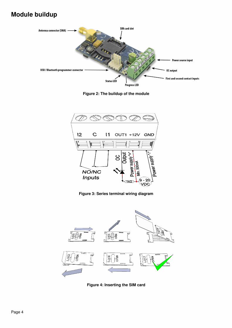
Module buildup
Figure 2: The buildup of the module
Figure 3: Series terminal wiring diagram
Figure 4: Inserting the SIM card
Page 5
Installation guide
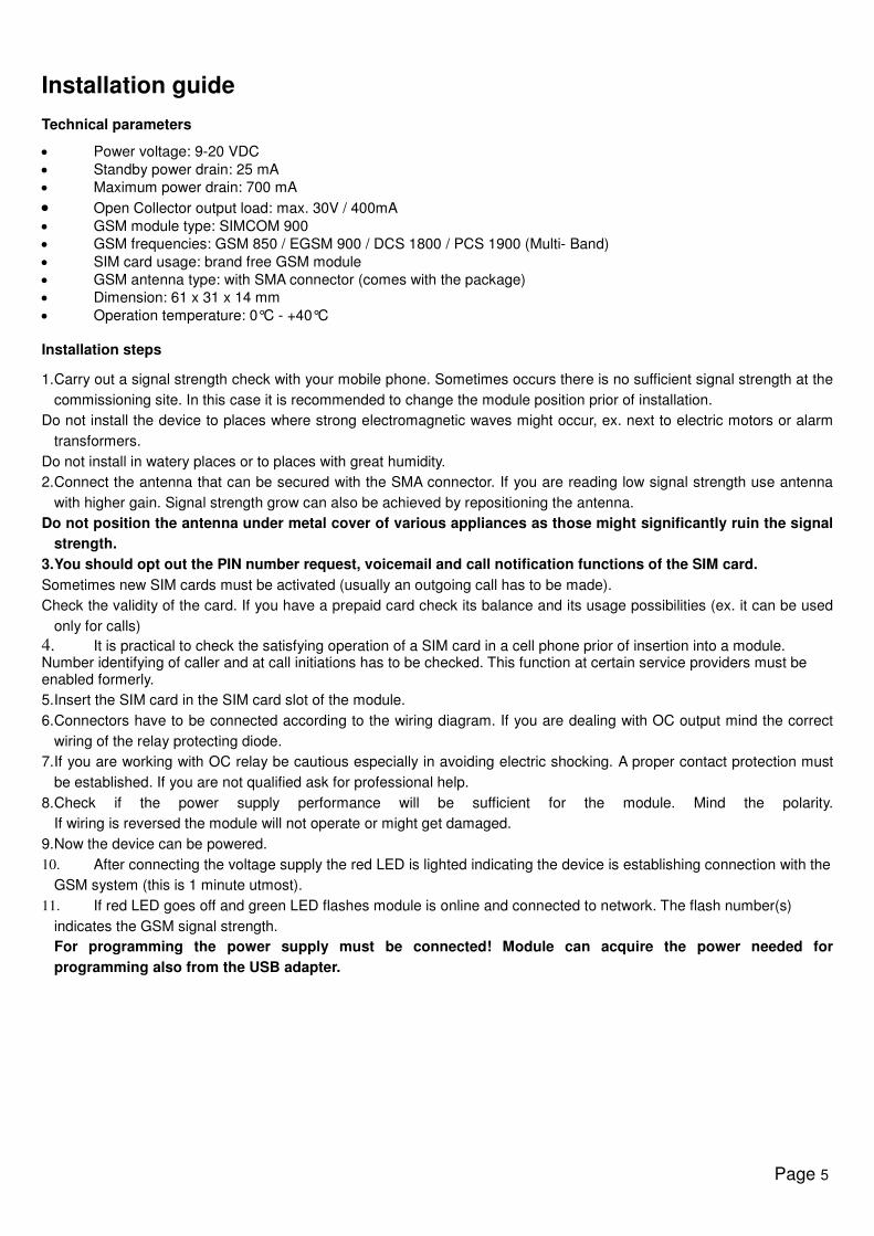
Technical parameters
• Power voltage: 9-20 VDC
• Standby power drain: 25 mA
• Maximum power drain: 700 mA
• Open Collector output load: max. 30V / 400mA
• GSM module type: SIMCOM 900
• GSM frequencies: GSM 850 / EGSM 900 / DCS 1800 / PCS 1900 (Multi- Band)
• SIM card usage: brand free GSM module
• GSM antenna type: with SMA connector (comes with the package)
• Dimension: 61 x 31 x 14 mm
• Operation temperature: 0°C - +40°C
Installation steps
1. Carry out a signal strength check with your mobile phone. Sometimes occurs there is no sufficient signal strength at the
commissioning site. In this case it is recommended to change the module position prior of installation.
Do not install the device to places where strong electromagnetic waves might occur, ex. next to electric motors or alarm
transformers.
Do not install in watery places or to places with great humidity.
2. Connect the antenna that can be secured with the SMA connector. If you are reading low signal strength use antenna
with higher gain. Signal strength grow can also be achieved by repositioning the antenna.
Do not position the antenna under metal cover of various appliances as those might significantly ruin the signal
strength.
3. You should opt out the PIN number request, voicemail and call notification functions of the SIM card.
Sometimes new SIM cards must be activated (usually an outgoing call has to be made).
Check the validity of the card. If you have a prepaid card check its balance and its usage possibilities (ex. it can be used
only for calls)
4. It is practical to check the satisfying operation of a SIM card in a cell phone prior of insertion into a module. Number identifying of caller and at call initiations has to be checked. This function at certain service providers must be enabled formerly.
5. Insert the SIM card in the SIM card slot of the module.
6. Connectors have to be connected according to the wiring diagram. If you are dealing with OC output mind the correct
wiring of the relay protecting diode.
7. If you are working with OC relay be cautious especially in avoiding electric shocking. A proper contact protection must
be established. If you are not qualified ask for professional help.
8. Check if the power supply performance will be sufficient for the module. Mind the polarity.
If wiring is reversed the module will not operate or might get damaged.
9. Now the device can be powered.
10. After connecting the voltage supply the red LED is lighted indicating the device is establishing connection with the
GSM system (this is 1 minute utmost).
11. If red LED goes off and green LED flashes module is online and connected to network. The flash number(s)
indicates the GSM signal strength.
For programming the power supply must be connected! Module can acquire the power needed for
programming also from the USB adapter.
Page 6
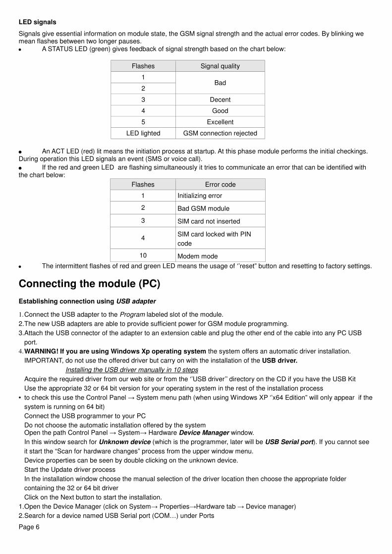
LED signals
Signals give essential information on module state, the GSM signal strength and the actual error codes. By blinking we mean flashes between two longer pauses.
• A STATUS LED (green) gives feedback of signal strength based on the chart below:
Flashes Signal quality
1 Bad
2
3 Decent
4 Good
5 Excellent
LED lighted GSM connection rejected
• An ACT LED (red) lit means the initiation process at startup. At this phase module performs the initial checkings. During operation this LED signals an event (SMS or voice call).
• If the red and green LED are flashing simultaneously it tries to communicate an error that can be identified with the chart below:
Flashes Error code
1 Initializing error
2 Bad GSM module
3 SIM card not inserted
4 SIM card locked with PIN
code
10 Modem mode
• The intermittent flashes of red and green LED means the usage of ‘’reset” button and resetting to factory settings.
Connecting the module (PC)
Establishing connection using USB adapter
1. Connect the USB adapter to the Program labeled slot of the module.
2. The new USB adapters are able to provide sufficient power for GSM module programming.
3. Attach the USB connector of the adapter to an extension cable and plug the other end of the cable into any PC USB
port.
4. WARNING! If you are using Windows Xp operating system the system offers an automatic driver installation.
IMPORTANT, do not use the offered driver but carry on with the installation of the USB driver.
Installing the USB driver manually in 10 steps
� Acquire the required driver from our web site or from the ‘’USB driver’’ directory on the CD if you have the USB Kit
� Use the appropriate 32 or 64 bit version for your operating system in the rest of the installation process
• to check this use the Control Panel → System menu path (when using Windows XP ‘’x64 Edition” will only appear if the
system is running on 64 bit)
� Connect the USB programmer to your PC
� Do not choose the automatic installation offered by the system
� Open the path Control Panel → System→ Hardware Device Manager window.
� In this window search for Unknown device (which is the programmer, later will be USB Serial port). If you cannot see
it start the “Scan for hardware changes” process from the upper window menu.
� Device properties can be seen by double clicking on the unknown device.
� Start the Update driver process
� In the installation window choose the manual selection of the driver location then choose the appropriate folder
containing the 32 or 64 bit driver
� Click on the Next button to start the installation.
1. Open the Device Manager (click on System→ Properties→Hardware tab → Device manager)
2. Search for a device named USB Serial port (COM…) under Ports
Page 7
• If a driver reinstall is needed click on the device then choose driver removal then follow instructions above.
1. Start the programming software.
2. You have to set the value in brackets [USB Serial port (COM…)] in the programming software
3. If this was successful you will see the name of the connected module next to the Start button
Establishing connection using a Bluetooth adapter
1. Connect the Bluetooth adapter to the GSM module and provide power to it.
2. Switch on the Bluetooth connection possibility on your device (PC or Android mobile phone).
3. Search for programmer with your Bluetooth enabled device.
4. After finding the adapter you can pair your PC/smart phone/tablet with the adapter by using the default ’’1234’’ code.
After pairing you will find the programmer as GSM Programmer.
5. Search for the COM port number of the connection (usually under Properties -> Hardware tab)
6. Set the port number also in your programming software or choose the automatic port finding option.
7. Establish a connection with the GSM module.
If you use Windows 8 operating system the programming software should be started in “Windows XP
SP2/SP3” compatibility mode (Right click on the starting icon of the program → Properties →
Compatibility)
In every case you can check the connection. You should see the connected module name next to the Start button in the
programming software and the green LED on the programmer to flash.
If you have a connection established between the adapter and your PC or smart phone you can start the module configuration. • By clicking the Start button after the connection was established modules settings will be acquired. • By clicking the Start/Default config button (after a confirmation) it will revert back the module to factory settings. • When using the Android application settings are always acquired after establishing a connection.
Programming using the PC software
• If you have chosen configuration by PC you can use our software that is freely downloadable from our website or you
can find it on the installation CD in the USB KIT.
• No installation required, you only have to copy the software to your PC.
• Compatible with Windows XP, 7 and 8
• Make sure you always use the latest software!
• If newer software is out the module should be updated prior to the first configuration.
•
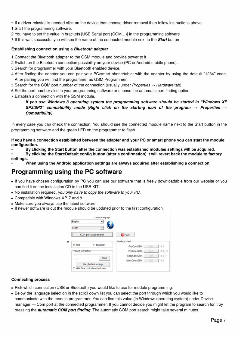
Connecting process
• Pick which connection (USB or Bluetooth) you would like to use for module programming.
• Below the language selection in the scroll down list you can select the port through which you would like to
communicate with the module programmer. You can find this value (in Windows operating system) under Device
manager → Com port at the connected programmer. If you cannot decide you might let the program to search for it by
pressing the automatic COM port finding. The automatic COM port search might take several minutes.
Page 8
• If the connection was successful you will see under the Product connection tab the name of the module.
• Clicking the start button the software makes connection to the module and configuration can be started.
• By clicking the Start/Default config button the module will be set back to default values after the connection was
established. (Before the operation the software asks for confirmation if this feature has not been switched off before).
• If you do not want to attach a module just to inspect the settings options you can select the Products-tryout window
where you can freely make a module properties selection and also module preprogramming.
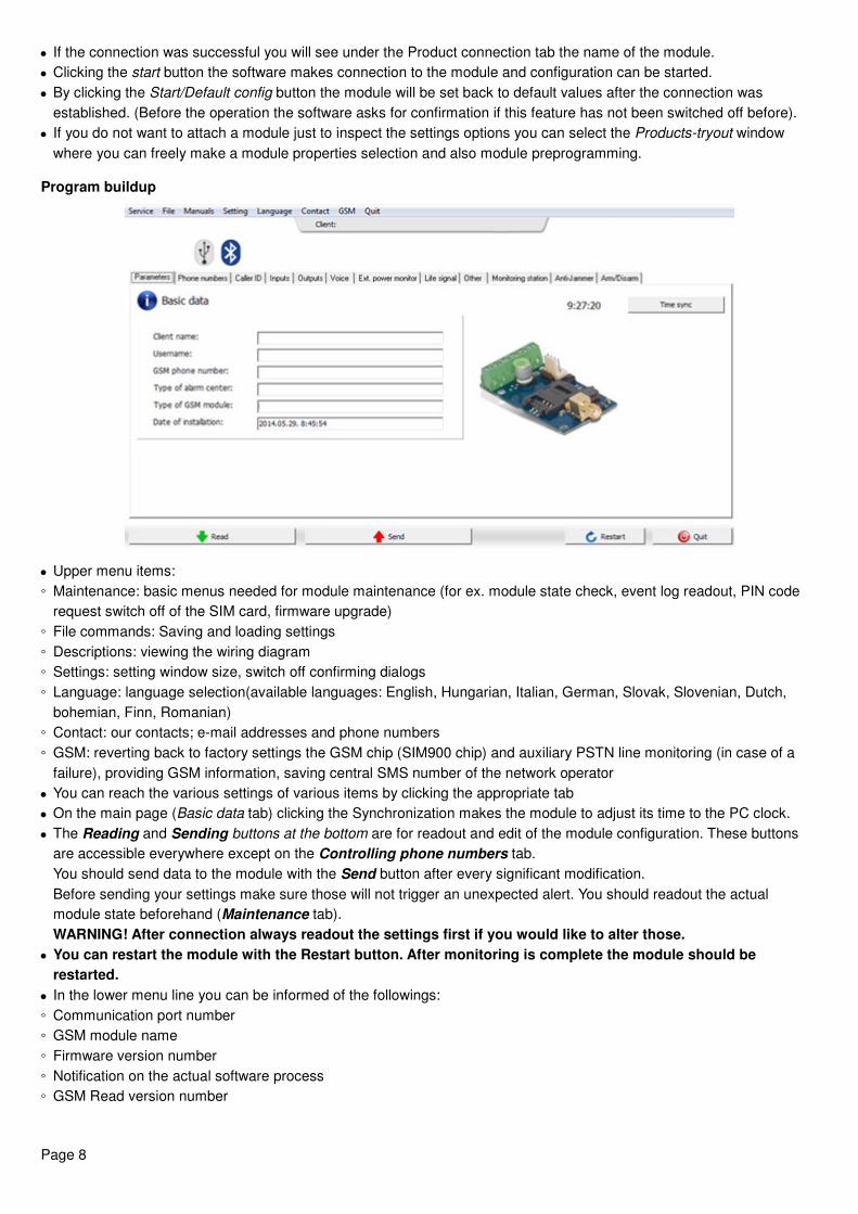
Program buildup
• Upper menu items:
◦ Maintenance: basic menus needed for module maintenance (for ex. module state check, event log readout, PIN code
request switch off of the SIM card, firmware upgrade)
◦ File commands: Saving and loading settings
◦ Descriptions: viewing the wiring diagram
◦ Settings: setting window size, switch off confirming dialogs
◦ Language: language selection(available languages: English, Hungarian, Italian, German, Slovak, Slovenian, Dutch,
bohemian, Finn, Romanian)
◦ Contact: our contacts; e-mail addresses and phone numbers
◦ GSM: reverting back to factory settings the GSM chip (SIM900 chip) and auxiliary PSTN line monitoring (in case of a
failure), providing GSM information, saving central SMS number of the network operator
• You can reach the various settings of various items by clicking the appropriate tab
• On the main page (Basic data tab) clicking the Synchronization makes the module to adjust its time to the PC clock.
• The Reading and Sending buttons at the bottom are for readout and edit of the module configuration. These buttons
are accessible everywhere except on the Controlling phone numbers tab.
You should send data to the module with the Send button after every significant modification.
Before sending your settings make sure those will not trigger an unexpected alert. You should readout the actual
module state beforehand (Maintenance tab).
WARNING! After connection always readout the settings first if you would like to alter those.
• You can restart the module with the Restart button. After monitoring is complete the module should be
restarted.
• In the lower menu line you can be informed of the followings:
◦ Communication port number
◦ GSM module name
◦ Firmware version number
◦ Notification on the actual software process
◦ GSM Read version number
Page 9
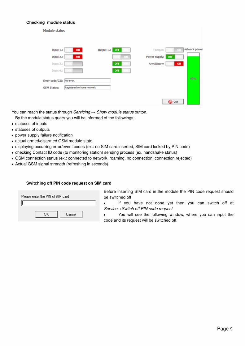
Checking module status
You can reach the status through Servicing → Show module status button.
By the module status query you will be informed of the followings:
• statuses of inputs
• statuses of outputs
• power supply failure notification
• actual armed/disarmed GSM module state
• displaying occurring error/event codes (ex.: no SIM card inserted, SIM card locked by PIN code)
• checking Contact ID code (to monitoring station) sending process (ex. handshake status)
• GSM connection status (ex.: connected to network, roaming, no connection, connection rejected)
• Actual GSM signal strength (refreshing in seconds)
Switching off PIN code request on SIM card
Before inserting SIM card in the module the PIN code request should
be switched off
• If you have not done yet then you can switch off at
Service→Switch off PIN code request.
• You will see the following window, where you can input the
code and its request will be switched off.
Page 10
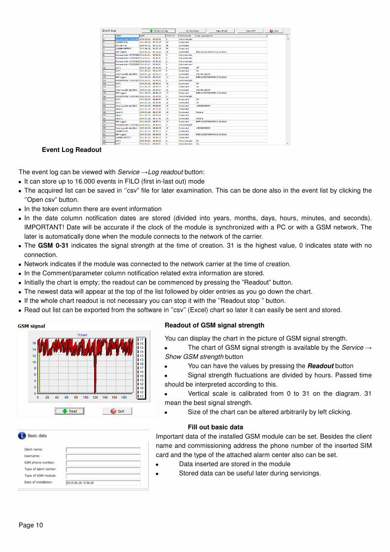
Event Log Readout
The event log can be viewed with Service →Log readout button:
• It can store up to 16.000 events in FILO (first in-last out) mode
• The acquired list can be saved in ‘’csv” file for later examination. This can be done also in the event list by clicking the
‘’Open csv” button.
• In the token column there are event information
• In the date column notification dates are stored (divided into years, months, days, hours, minutes, and seconds).
IMPORTANT! Date will be accurate if the clock of the module is synchronized with a PC or with a GSM network. The
later is automatically done when the module connects to the network of the carrier.
• The GSM 0-31 indicates the signal strength at the time of creation. 31 is the highest value, 0 indicates state with no
connection.
• Network indicates if the module was connected to the network carrier at the time of creation.
• In the Comment/parameter column notification related extra information are stored.
• Initially the chart is empty; the readout can be commenced by pressing the ”Readout” button.
• The newest data will appear at the top of the list followed by older entries as you go down the chart.
• If the whole chart readout is not necessary you can stop it with the ’’Readout stop ’’ button.
• Read out list can be exported from the software in ’’csv’’ (Excel) chart so later it can easily be sent and stored.
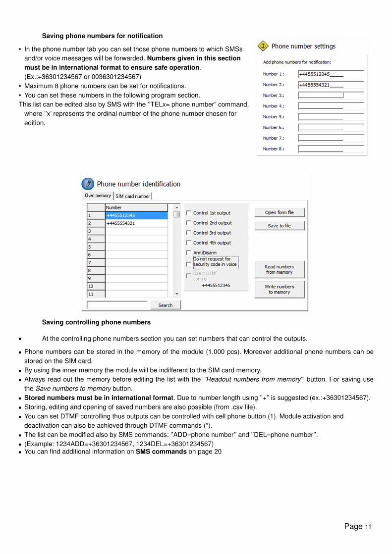
Readout of GSM signal strength
You can display the chart in the picture of GSM signal strength.
• The chart of GSM signal strength is available by the Service →
Show GSM strength button
• You can have the values by pressing the Readout button
• Signal strength fluctuations are divided by hours. Passed time
should be interpreted according to this.
• Vertical scale is calibrated from 0 to 31 on the diagram. 31
mean the best signal strength.
• Size of the chart can be altered arbitrarily by left clicking.
Fill out basic data
Important data of the installed GSM module can be set. Besides the client
name and commissioning address the phone number of the inserted SIM
card and the type of the attached alarm center also can be set.
• Data inserted are stored in the module
• Stored data can be useful later during servicings.
Page 11
Saving phone numbers for notification
• In the phone number tab you can set those phone numbers to which SMSs
and/or voice messages will be forwarded. Numbers given in this section
must be in international format to ensure safe operation.
(Ex.:+36301234567 or 0036301234567)
• Maximum 8 phone numbers can be set for notifications.
• You can set these numbers in the following program section.
This list can be edited also by SMS with the ’’TELx= phone number” command,
where ’’x’ represents the ordinal number of the phone number chosen for
edition.
Saving controlling phone numbers
• At the controlling phone numbers section you can set numbers that can control the outputs.
• Phone numbers can be stored in the memory of the module (1.000 pcs). Moreover additional phone numbers can be
stored on the SIM card.
• By using the inner memory the module will be indifferent to the SIM card memory.
• Always read out the memory before editing the list with the ’’Readout numbers from memory’” button. For saving use
the Save numbers to memory button.
• Stored numbers must be in international format. Due to number length using ’’+’’ is suggested (ex.:+36301234567).
• Storing, editing and opening of saved numbers are also possible (from .csv file).
• You can set DTMF controlling thus outputs can be controlled with cell phone button (1). Module activation and
deactivation can also be achieved through DTMF commands (*).
• The list can be modified also by SMS commands: ’’ADD=phone number’’ and ’’DEL=phone number’’.
• (Example: 1234ADD=+36301234567, 1234DEL=+36301234567)
• You can find additional information on SMS commands on page 20
Page 12
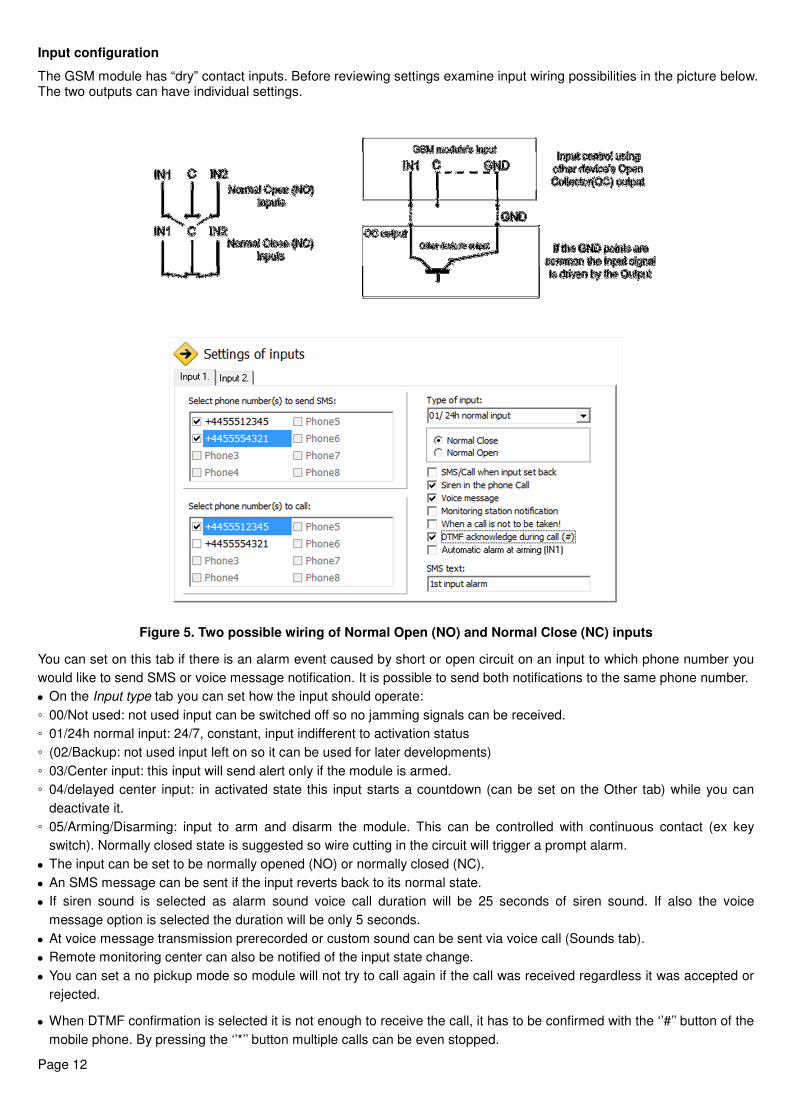
Input configuration
The GSM module has “dry” contact inputs. Before reviewing settings examine input wiring possibilities in the picture below. The two outputs can have individual settings.
Figure 5. Two possible wiring of Normal Open (NO) and Normal Close (NC) inputs
You can set on this tab if there is an alarm event caused by short or open circuit on an input to which phone number you
would like to send SMS or voice message notification. It is possible to send both notifications to the same phone number.
• On the Input type tab you can set how the input should operate:
◦ 00/Not used: not used input can be switched off so no jamming signals can be received.
◦ 01/24h normal input: 24/7, constant, input indifferent to activation status
◦ (02/Backup: not used input left on so it can be used for later developments)
◦ 03/Center input: this input will send alert only if the module is armed.
◦ 04/delayed center input: in activated state this input starts a countdown (can be set on the Other tab) while you can
deactivate it.
◦ 05/Arming/Disarming: input to arm and disarm the module. This can be controlled with continuous contact (ex key
switch). Normally closed state is suggested so wire cutting in the circuit will trigger a prompt alarm.
• The input can be set to be normally opened (NO) or normally closed (NC).
• An SMS message can be sent if the input reverts back to its normal state.
• If siren sound is selected as alarm sound voice call duration will be 25 seconds of siren sound. If also the voice
message option is selected the duration will be only 5 seconds.
• At voice message transmission prerecorded or custom sound can be sent via voice call (Sounds tab).
• Remote monitoring center can also be notified of the input state change.
• You can set a no pickup mode so module will not try to call again if the call was received regardless it was accepted or
rejected.
• When DTMF confirmation is selected it is not enough to receive the call, it has to be confirmed with the ‘’#’’ button of the
mobile phone. By pressing the ‘’*’’ button multiple calls can be even stopped.
Page 13
• The first input can be set to send notification if module is powered on. Thus the module indifferent to its state will initiate
an alarm event. This function is suggested when you want the module power-on to initiate an alarm event.
• In the SMS message box you can set the message that can be maximum 32 characters long.
• Input modifications can be achieved by SMS commands with the following parameters:
• 1234INPUT1=tnneeeeeeee
• t: 0 → switched off 1 →24h normal 2 → backup 3 → alarm normal 4 → alarm delayed nn → NO or NC eeeeeeee: Other
parameters: 1.e=1 → Message of reverting back 2.3=0 → Compulsory 0 3.e =1 → siren sound 4.e=1 → Voice message
5.e=1 → Monitoring station 6.e=1 →no need to pickup at call 7.e=1 → DTMF acknowledge (#) 8.e=0 → Compulsory 0
• You can find additional information on SMS commands on page 20.
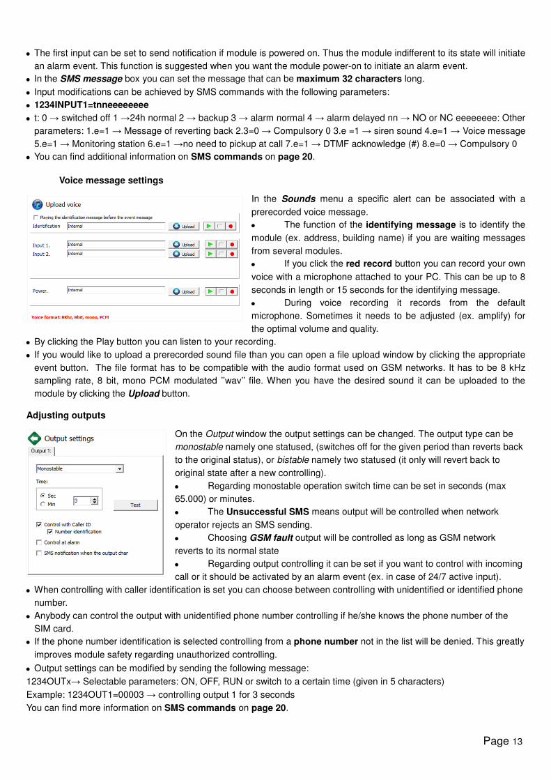
Voice message settings
In the Sounds menu a specific alert can be associated with a
prerecorded voice message.
• The function of the identifying message is to identify the
module (ex. address, building name) if you are waiting messages
from several modules.
• If you click the red record button you can record your own
voice with a microphone attached to your PC. This can be up to 8
seconds in length or 15 seconds for the identifying message.
• During voice recording it records from the default
microphone. Sometimes it needs to be adjusted (ex. amplify) for
the optimal volume and quality.
• By clicking the Play button you can listen to your recording.
• If you would like to upload a prerecorded sound file than you can open a file upload window by clicking the appropriate
event button. The file format has to be compatible with the audio format used on GSM networks. It has to be 8 kHz
sampling rate, 8 bit, mono PCM modulated ’’wav’’ file. When you have the desired sound it can be uploaded to the
module by clicking the Upload button.
Adjusting outputs
On the Output window the output settings can be changed. The output type can be
monostable namely one statused, (switches off for the given period than reverts back
to the original status), or bistable namely two statused (it only will revert back to
original state after a new controlling).
• Regarding monostable operation switch time can be set in seconds (max
65.000) or minutes.
• The Unsuccessful SMS means output will be controlled when network
operator rejects an SMS sending.
• Choosing GSM fault output will be controlled as long as GSM network
reverts to its normal state
• Regarding output controlling it can be set if you want to control with incoming
call or it should be activated by an alarm event (ex. in case of 24/7 active input).
• When controlling with caller identification is set you can choose between controlling with unidentified or identified phone
number.
• Anybody can control the output with unidentified phone number controlling if he/she knows the phone number of the
SIM card.
• If the phone number identification is selected controlling from a phone number not in the list will be denied. This greatly
improves module safety regarding unauthorized controlling.
• Output settings can be modified by sending the following message:
1234OUTx→ Selectable parameters: ON, OFF, RUN or switch to a certain time (given in 5 characters)
Example: 1234OUT1=00003 → controlling output 1 for 3 seconds
You can find more information on SMS commands on page 20.
Page 14
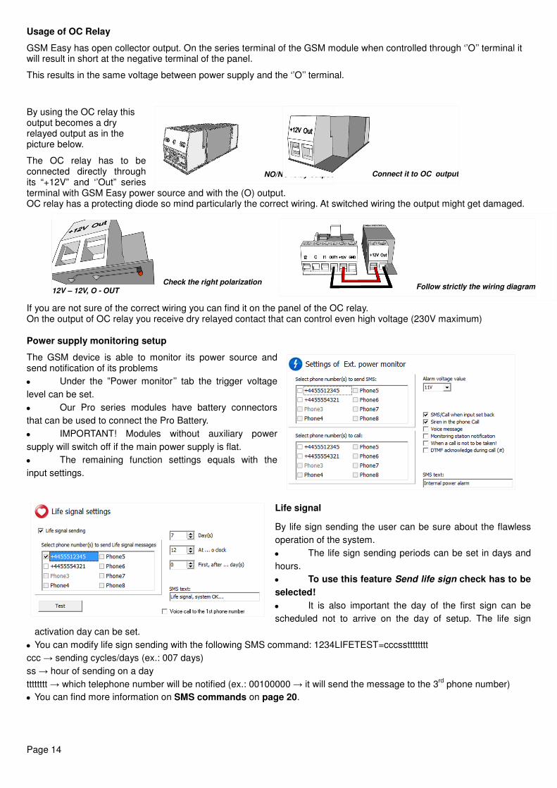
Usage of OC Relay
GSM Easy has open collector output. On the series terminal of the GSM module when controlled through ‘’O’’ terminal it will result in short at the negative terminal of the panel.
This results in the same voltage between power supply and the ‘’O’’ terminal.
By using the OC relay this output becomes a dry relayed output as in the picture below.
The OC relay has to be connected directly through its “+12V” and ‘’Out” series terminal with GSM Easy power source and with the (O) output. OC relay has a protecting diode so mind particularly the correct wiring. At switched wiring the output might get damaged.
If you are not sure of the correct wiring you can find it on the panel of the OC relay. On the output of OC relay you receive dry relayed contact that can control even high voltage (230V maximum)
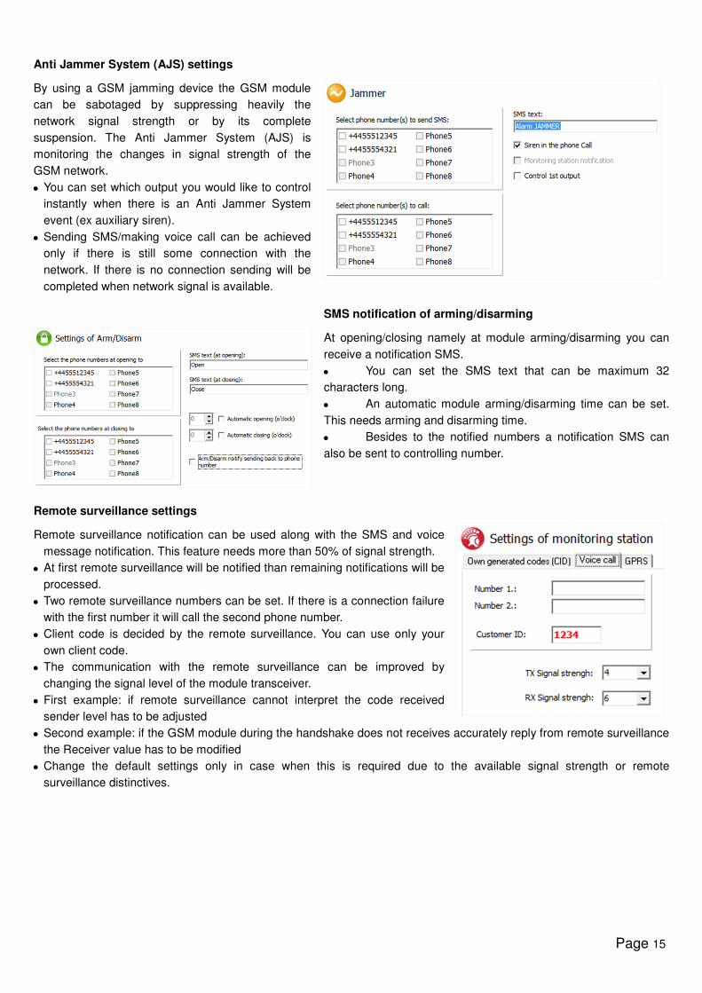
Power supply monitoring setup
The GSM device is able to monitor its power source and send notification of its problems
• Under the ”Power monitor’’ tab the trigger voltage
level can be set.
• Our Pro series modules have battery connectors
that can be used to connect the Pro Battery.
• IMPORTANT! Modules without auxiliary power
supply will switch off if the main power supply is flat.
• The remaining function settings equals with the
input settings.
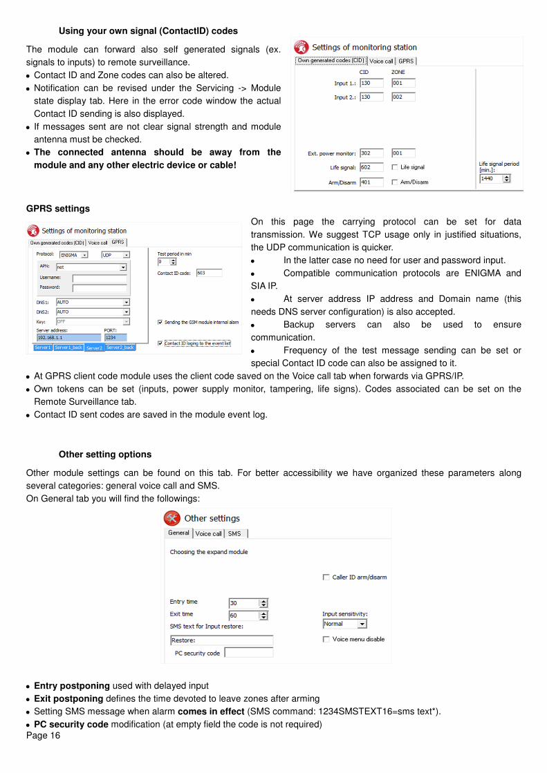
Life signal
By life sign sending the user can be sure about the flawless
operation of the system.
• The life sign sending periods can be set in days and
hours.
• To use this feature Send life sign check has to be
selected!
• It is also important the day of the first sign can be
scheduled not to arrive on the day of setup. The life sign
activation day can be set.
• You can modify life sign sending with the following SMS command: 1234LIFETEST=cccsstttttttt
ccc → sending cycles/days (ex.: 007 days)
ss → hour of sending on a day
tttttttt → which telephone number will be notified (ex.: 00100000 → it will send the message to the 3rd
phone number)
• You can find more information on SMS commands on page 20.
NO/NC relay output Connect it to OC output
Check the right polarization 12V – 12V, O - OUT Follow strictly the wiring diagram
Page 15
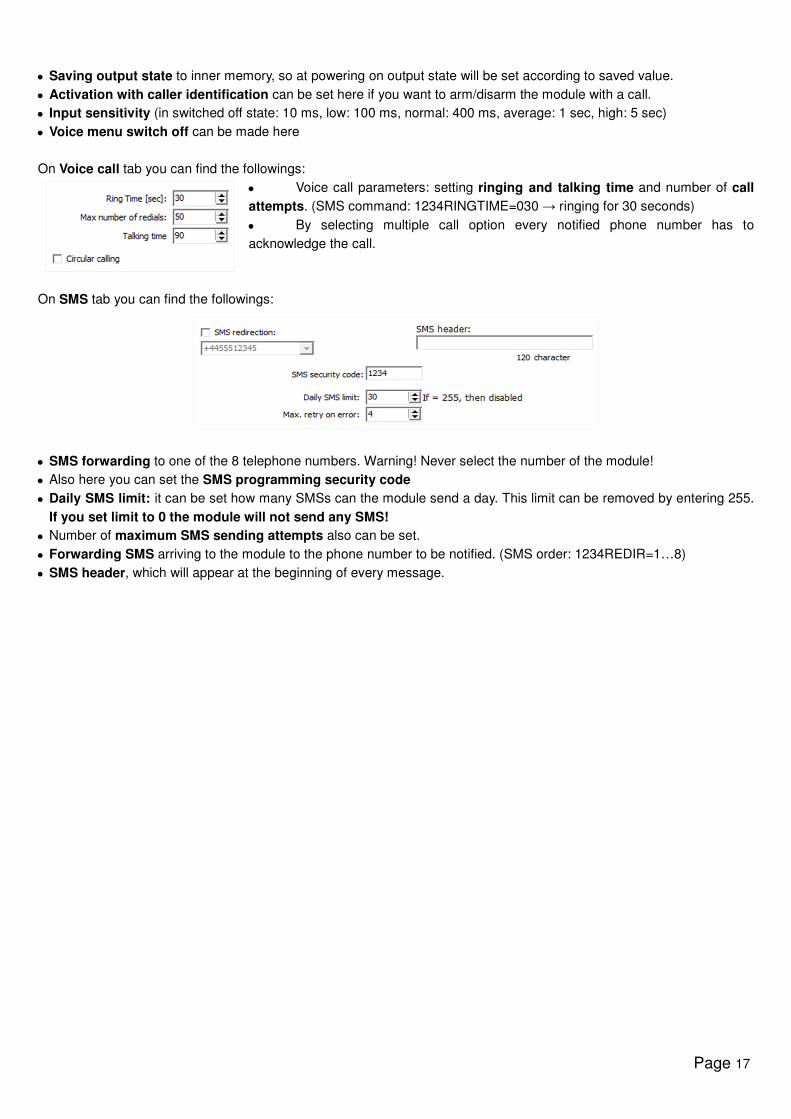
Anti Jammer System (AJS) settings
By using a GSM jamming device the GSM module
can be sabotaged by suppressing heavily the
network signal strength or by its complete
suspension. The Anti Jammer System (AJS) is
monitoring the changes in signal strength of the
GSM network.
• You can set which output you would like to control
instantly when there is an Anti Jammer System
event (ex auxiliary siren).
• Sending SMS/making voice call can be achieved
only if there is still some connection with the
network. If there is no connection sending will be
completed when network signal is available.
SMS notification of arming/disarming
At opening/closing namely at module arming/disarming you can
receive a notification SMS.
• You can set the SMS text that can be maximum 32
characters long.
• An automatic module arming/disarming time can be set.
This needs arming and disarming time.
• Besides to the notified numbers a notification SMS can
also be sent to controlling number.
Remote surveillance settings
Remote surveillance notification can be used along with the SMS and voice
message notification. This feature needs more than 50% of signal strength.
• At first remote surveillance will be notified than remaining notifications will be
processed.
• Two remote surveillance numbers can be set. If there is a connection failure
with the first number it will call the second phone number.
• Client code is decided by the remote surveillance. You can use only your
own client code.
• The communication with the remote surveillance can be improved by
changing the signal level of the module transceiver.
• First example: if remote surveillance cannot interpret the code received
sender level has to be adjusted
• Second example: if the GSM module during the handshake does not receives accurately reply from remote surveillance
the Receiver value has to be modified
• Change the default settings only in case when this is required due to the available signal strength or remote
surveillance distinctives.
Page 16
Using your own signal (ContactID) codes
The module can forward also self generated signals (ex.
signals to inputs) to remote surveillance.
• Contact ID and Zone codes can also be altered.
• Notification can be revised under the Servicing -> Module
state display tab. Here in the error code window the actual
Contact ID sending is also displayed.
• If messages sent are not clear signal strength and module
antenna must be checked.
• The connected antenna should be away from the
module and any other electric device or cable!
GPRS settings
On this page the carrying protocol can be set for data
transmission. We suggest TCP usage only in justified situations,
the UDP communication is quicker.
• In the latter case no need for user and password input.
• Compatible communication protocols are ENIGMA and
SIA IP.
• At server address IP address and Domain name (this
needs DNS server configuration) is also accepted.
• Backup servers can also be used to ensure
communication.
• Frequency of the test message sending can be set or
special Contact ID code can also be assigned to it.
• At GPRS client code module uses the client code saved on the Voice call tab when forwards via GPRS/IP.
• Own tokens can be set (inputs, power supply monitor, tampering, life signs). Codes associated can be set on the
Remote Surveillance tab.
• Contact ID sent codes are saved in the module event log.
Other setting options
Other module settings can be found on this tab. For better accessibility we have organized these parameters along
several categories: general voice call and SMS.
On General tab you will find the followings:
• Entry postponing used with delayed input
• Exit postponing defines the time devoted to leave zones after arming
• Setting SMS message when alarm comes in effect (SMS command: 1234SMSTEXT16=sms text*).
• PC security code modification (at empty field the code is not required)
Page 17
• Saving output state to inner memory, so at powering on output state will be set according to saved value.
• Activation with caller identification can be set here if you want to arm/disarm the module with a call.
• Input sensitivity (in switched off state: 10 ms, low: 100 ms, normal: 400 ms, average: 1 sec, high: 5 sec)
• Voice menu switch off can be made here
On Voice call tab you can find the followings:
• Voice call parameters: setting ringing and talking time and number of call
attempts. (SMS command: 1234RINGTIME=030 → ringing for 30 seconds)
• By selecting multiple call option every notified phone number has to
acknowledge the call.
On SMS tab you can find the followings:
• SMS forwarding to one of the 8 telephone numbers. Warning! Never select the number of the module!
• Also here you can set the SMS programming security code
• Daily SMS limit: it can be set how many SMSs can the module send a day. This limit can be removed by entering 255.
If you set limit to 0 the module will not send any SMS!
• Number of maximum SMS sending attempts also can be set.
• Forwarding SMS arriving to the module to the phone number to be notified. (SMS order: 1234REDIR=1…8)
• SMS header, which will appear at the beginning of every message.
Page 18
Programming with Android based mobile phone
Starting the program
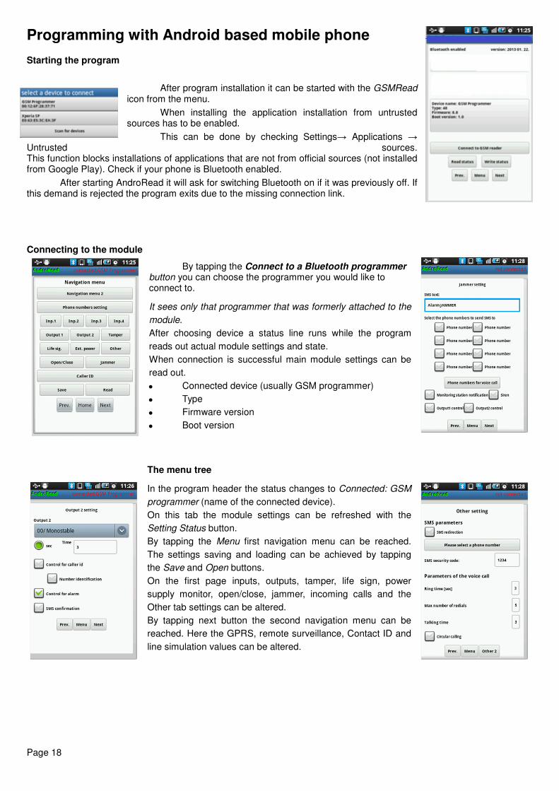
After program installation it can be started with the GSMRead icon from the menu.
When installing the application installation from untrusted sources has to be enabled.
This can be done by checking Settings→ Applications → Untrusted sources. This function blocks installations of applications that are not from official sources (not installed from Google Play). Check if your phone is Bluetooth enabled.
After starting AndroRead it will ask for switching Bluetooth on if it was previously off. If this demand is rejected the program exits due to the missing connection link. Connecting to the module
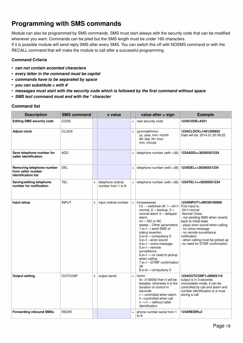
By tapping the Connect to a Bluetooth programmer button you can choose the programmer you would like to connect to.
It sees only that programmer that was formerly attached to the
module.
After choosing device a status line runs while the program
reads out actual module settings and state.
When connection is successful main module settings can be
read out.
• Connected device (usually GSM programmer)
• Type
• Firmware version
• Boot version
The menu tree
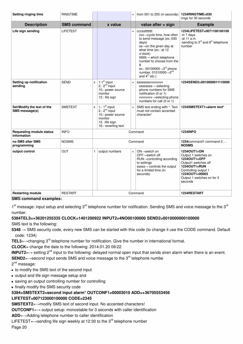
In the program header the status changes to Connected: GSM
programmer (name of the connected device).
On this tab the module settings can be refreshed with the
Setting Status button.
By tapping the Menu first navigation menu can be reached.
The settings saving and loading can be achieved by tapping
the Save and Open buttons.
On the first page inputs, outputs, tamper, life sign, power
supply monitor, open/close, jammer, incoming calls and the
Other tab settings can be altered.
By tapping next button the second navigation menu can be
reached. Here the GPRS, remote surveillance, Contact ID and
line simulation values can be altered.
Page 19
Programming with SMS commands
Module can also be programmed by SMS commands. SMS must start always with the security code that can be modified
whenever you want. Commands can be piled but the SMS length must be under 160 characters.
If it is possible module will send reply SMS after every SMS. You can switch this off with NOSMS command or with the
RECALL command that will make the module to call after a successful programming.
Command Criteria
• can not contain accented characters
• every letter in the command must be capital
• commands have to be separated by space
• you can substitute = with #
• messages must start with the security code which is followed by the first command without space
• SMS text command must end with the * character
Command list
Description SMS command x value value after = sign Example
Editing SMS security code CODE = new security code 1234CODE=4321
Adjust clock CLOCK = yymmddhhmm yy: year, mm: month dd: day, hh: hour mm: minute
1234CLOCK=1401200922 Date will be: 2014.01.20 09:22
Save telephone number for caller identification
ADD = telephone number (with +36) 1234ADD=+36305551234
Removing telephone number from caller number identification list
DEL = telephone number (with +36) 1234DEL=+36305551234
Saving/editing telephone number for notification
TEL x telephone ordinal number from 1 to 8
= telephone number (with +36) 1234TEL1=+36305551234
Input setup INPUT x input ordinal number = tnneeeeeeee t:0 → switched off, 1→24 h normal, 2→ backup; 3→ normal alarm 4→ delayed alarm nn→ NO or NC eeeee..: Other parameters: 1.e=1→ send SMS of status revertion 2.e=0→ compulsory 0 3.e=1→siren sound 4.e=1→voice message 5.e=1→remote surveillance 6.e=1→ no need to pickup when calling 7.e=1→DTMF confirmation (#) 8.e=0→ compulsory 0
1234INPUT1=INC00100000 First input is: -24 h normal -Normal Close - not sending SMS when reverts back to initial state - plays siren sound when calling - no voice message - no remote surveillance notification - when calling must be picked up -no need for DTMF confirmation
Output setting OUTCONF x output serial = iiiiirhn iiii→if 00000 then it will be bistable, otherwise it is the duration of control in seconds r→ controlled when alarm h→controlled when call n→=1→ without caller identification
1234OUTCONF1=00003110 output is in 3 seconds monostable mode, it can be controlled by call and alarm and number identification is a must during a call
Forwarding inbound SMSs REDIR = phone number serial from 1 to 8
1234REDIR=2
Page 20
Setting ringing time RINGTIME = from 001 to 255 (in seconds) 1234RINGTIME=030 rings for 30 seconds
Description SMS command x value value after = sign Example
Life sign sending LIFETEST = cccsstttttttt ccc→cycle time, how often to send message (ex.:030 days) ss→on the given day at what time (ex.: at 12 o’clock) tttttttt→ which telephone number to choose from the 8 ex.: 00100000→3
rd phone
number, 01010000→2nd
and 4
th etc.)
1234LIFETEST=0071100100100 -in 7 days -at 11 a.m. -sending to 3
rd and 6
th telephone
number
Setting up notification sending
SEND x 1:1st input
2.: 2nd
input 10.: power source monitor 12.: life sign
= ssssssssvvvvvvvv ssssssss→ selecting phone numbers for SMS notification (0 or 1) vvvvvvvv→selecting phone numbers for call (0 or 1)
1234SEND2=0010000011110000
Set/Modify the text of the SMS message(s)
SMSTEXT x 1.: 1st input
2.: 2nd
input 10.: power source monitor 12. :life sign 16.: reverting text
= SMS text ending with *. Text must not contain accented character!
1234SMSTEXT1=alarm text*
Requesting module status information
INFO Command 1234INFO
no SMS after SMS programming
NOSMS Command 1234command1 command 2 … NOSMS
output control OUT 1 output numbers = ON→switch on OFF→switch off RUN→controlling according to settings sssss→ controls the output for a limited time (in seconds)
1234OUT1=ON Output 1 switches on 1234OUT1=OFF Output1 switches off 1234OUT1=RUN Controlling output 1 1234OUT1=00003 Output 1 switches on for 3 seconds
Restarting module RESTART Command 1234RESTART
SMS command examples:
1st message: input setup and selecting 3
rd telephone number for notification. Sending SMS and voice message to the 3
rd
number.
5384TEL3=+36201255335 CLOCK=1401200922 INPUT2=4NO00100000 SEND2=0010000000100000
SMS text is the following:
5348 → SMS security code, every new SMS can be started with this code (to change it use the CODE command. Default
code: 1234)
TEL3=→changing 3rd
telephone number for notification. Give the number in international format.
CLOCK= change the date to the following: 2014.01.20 09:22
INPUT2=→ setting 2nd
input to the following: delayed normal open input that sends siren alarm when there is an event.
SEND2=→second input sends SMS and voice message to the 3rd
telephone numbe
2nd
message:
• to modify the SMS text of the second input
• output and life sign message setup and
• saving an output controlling number for controlling
• finally modify the SMS security code
5384=SMSTEXT2=second input alarm* OUTCONF1=00003010 ADD=+36705553456
LIFETEST=007123000100000 CODE=2345
SMSTEXT2=→modify SMS text of second input. No accented characters!
OUTCONF1=→ output setup: monostable for 3 seconds with caller identification
ADD=→Adding telephone number to caller identification
LIFETEST=→sending life sign weekly at 12:30 to the 3rd
telephone number
Page 21
GSM gate control compact view
Similar to the entryphone compact view GSM gate control settings have their separate interface. The new interface
contains every significant function for establishing a GSM based gate control system.
To activate the interface on the Connection window the Gate control compact view checkbox has to be marked
The new interface contains:
• output (gates) configuration: monostable (timed) or bistable (two stated) controlling
• controlling with caller identification, assigning phone numbers to gates and direct DTMF control
• SMS and PC security code
• firmware update
• switch off PIN code request of the SIM card
• event log, GSM signal strength and showing actual GSM module status
• wiring diagrams
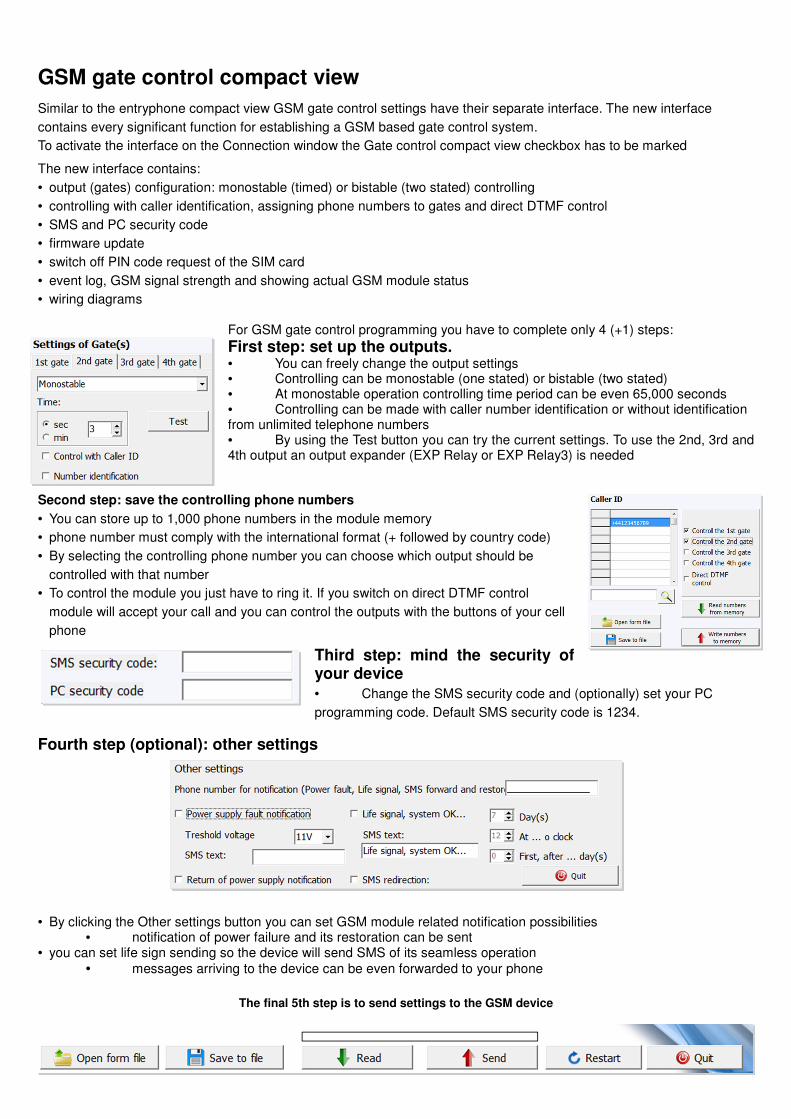
For GSM gate control programming you have to complete only 4 (+1) steps:
First step: set up the outputs. • You can freely change the output settings • Controlling can be monostable (one stated) or bistable (two stated) • At monostable operation controlling time period can be even 65,000 seconds • Controlling can be made with caller number identification or without identification from unlimited telephone numbers • By using the Test button you can try the current settings. To use the 2nd, 3rd and 4th output an output expander (EXP Relay or EXP Relay3) is needed
Second step: save the controlling phone numbers
• You can store up to 1,000 phone numbers in the module memory
• phone number must comply with the international format (+ followed by country code)
• By selecting the controlling phone number you can choose which output should be
controlled with that number
• To control the module you just have to ring it. If you switch on direct DTMF control
module will accept your call and you can control the outputs with the buttons of your cell
phone
Third step: mind the security of your device
• Change the SMS security code and (optionally) set your PC
programming code. Default SMS security code is 1234.
Fourth step (optional): other settings
• By clicking the Other settings button you can set GSM module related notification possibilities • notification of power failure and its restoration can be sent
• you can set life sign sending so the device will send SMS of its seamless operation
• messages arriving to the device can be even forwarded to your phone
The final 5th step is to send settings to the GSM device