Embed Size (px)
Citation preview

User ManualGrow CO2 Controller
Testing set, BEFORE INSTALLATIONThe different sets are delivered pre-connected in the package. Always test the set before installation to verify proper function!1. Open the box and carefully take the components
out of the package.2. Find the power supply in the package and attach
the correct mains-adaptor for your country’s outlet, then connect the power supply to the electrical outlet. The set should now activate.
3. Check that all LEDs on the Grow CO2 Controller illuminate and that the built-in buzzers beep. This is part of the selfdiagnostics program.
4. Now your product is tested and you can start the installation.
Technical specificationsPower supply: 24V DC Mains power supply: Transient overvoltages up to the levels of overvoltage category II. NOTE: These levels of transient overvoltage are typical for equipment supplied from the building wiring.Current consumption with solenoid valve: Max 280 mAMeasurement range: 0-5000 ppm CO2- concentrationAltitude: Calibrated for altitude up to 5000 m.Pollution degree: 2Serial communication: Modbus protocol over RS485Automatic calibration: At regular intervalsOperating temperature: Calibrated for operating between 32 – 115F (Sensor functions from -5F ) Calibrated for operating between 0 to 45˚C (Sensor works from -20°C) but values valid only for 0-45°C).Operating humidity: 0-95% RH non condensedStorage temperature: -40 to + 70˚C
ENGLISH
Grow CO2 Controller for grow room and greenhouse.
! WARNING!
Please read these instructions carefully prior to start-up and use. These instructions should be saved for future reference and passed on to any subsequent owner. Failure to follow any of these instructions could result in bodily harm or death, and could void product warranties. LogiCO2 International AB, its affiliates and third party providers assume no responsibility for claims arising from improper or careless use or handling of its products. Retain this instruction.
LEGAL NOTICEAll persons responsible for the operation and maintenance of this equipment must read and understand the safety and operating information contained in this guide. Installation and service of this equipment should be performed only by professionals. The function of the equipment will be impaired if it is not properly installed. Disconnection from supply source: When installing the Grow CO2 Controller to the power net, please ensure that the fuse that the system runs on is clearly marked. This makes it easy to disconnect the power to the system, if needed. It is very important to be aware that the Grow CO2 Controller does not function if disconnected from power mains.
2
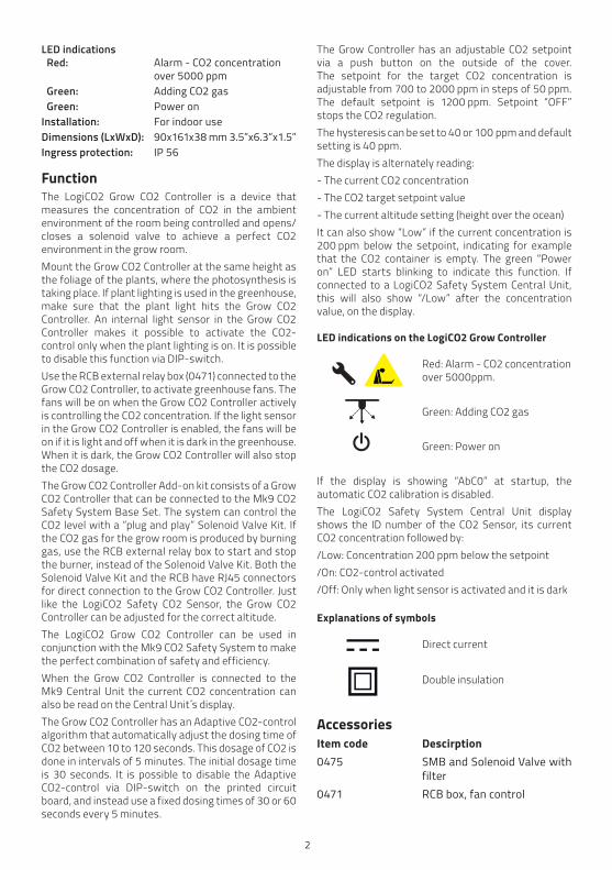
LED indications Red: Alarm - CO2 concentration over 5000 ppm Green: Adding CO2 gas Green: Power onInstallation: For indoor useDimensions (LxWxD): 90x161x38 mm 3.5”x6.3”x1.5”Ingress protection: IP 56
FunctionThe LogiCO2 Grow CO2 Controller is a device that measures the concentration of CO2 in the ambient environment of the room being controlled and opens/closes a solenoid valve to achieve a perfect CO2 environment in the grow room. Mount the Grow CO2 Controller at the same height as the foliage of the plants, where the photosynthesis is taking place. If plant lighting is used in the greenhouse, make sure that the plant light hits the Grow CO2 Controller. An internal light sensor in the Grow CO2 Controller makes it possible to activate the CO2-control only when the plant lighting is on. It is possible to disable this function via DIP-switch.Use the RCB external relay box (0471) connected to the Grow CO2 Controller, to activate greenhouse fans. The fans will be on when the Grow CO2 Controller actively is controlling the CO2 concentration. If the light sensor in the Grow CO2 Controller is enabled, the fans will be on if it is light and off when it is dark in the greenhouse. When it is dark, the Grow CO2 Controller will also stop the CO2 dosage.The Grow CO2 Controller Add-on kit consists of a Grow CO2 Controller that can be connected to the Mk9 CO2 Safety System Base Set. The system can control the CO2 level with a “plug and play” Solenoid Valve Kit. If the CO2 gas for the grow room is produced by burning gas, use the RCB external relay box to start and stop the burner, instead of the Solenoid Valve Kit. Both the Solenoid Valve Kit and the RCB have RJ45 connectors for direct connection to the Grow CO2 Controller. Just like the LogiCO2 Safety CO2 Sensor, the Grow CO2 Controller can be adjusted for the correct altitude.The LogiCO2 Grow CO2 Controller can be used in conjunction with the Mk9 CO2 Safety System to make the perfect combination of safety and efficiency.When the Grow CO2 Controller is connected to the Mk9 Central Unit the current CO2 concentration can also be read on the Central Unit´s display. The Grow CO2 Controller has an Adaptive CO2-control algorithm that automatically adjust the dosing time of CO2 between 10 to 120 seconds. This dosage of CO2 is done in intervals of 5 minutes. The initial dosage time is 30 seconds. It is possible to disable the Adaptive CO2-control via DIP-switch on the printed circuit board, and instead use a fixed dosing times of 30 or 60 seconds every 5 minutes.
The Grow Controller has an adjustable CO2 setpoint via a push button on the outside of the cover.The setpoint for the target CO2 concentration is adjustable from 700 to 2000 ppm in steps of 50 ppm. The default setpoint is 1200 ppm. Setpoint “OFF” stops the CO2 regulation.The hysteresis can be set to 40 or 100 ppm and default setting is 40 ppm.The display is alternately reading:- The current CO2 concentration- The CO2 target setpoint value- The current altitude setting (height over the ocean)It can also show “Low” if the current concentration is 200 ppm below the setpoint, indicating for example that the CO2 container is empty. The green “Power on” LED starts blinking to indicate this function. If connected to a LogiCO2 Safety System Central Unit, this will also show “/Low” after the concentration value, on the display.
LED indications on the LogiCO2 Grow Controller
Red: Alarm - CO2 concentration over 5000ppm.
Green: Adding CO2 gas
Green: Power on
If the display is showing “AbC0” at startup, the automatic CO2 calibration is disabled.The LogiCO2 Safety System Central Unit display shows the ID number of the CO2 Sensor, its current CO2 concentration followed by:/Low: Concentration 200 ppm below the setpoint/On: CO2-control activated/Off: Only when light sensor is activated and it is dark
Explanations of symbols
Direct current
Double insulation
AccessoriesItem code Descirption0475 SMB and Solenoid Valve with filter0471 RCB box, fan control

3
Display signs
Temp Low
ppm SW Setpoint
CO2 F°C
Shown only when enabled
Software version at start. After start-up, the “SW” indicates that the plant light is on (if enabled)
Shown together with CO2 Setpoint target value
Low is shown when thecurrent CO2-concentration is 200 ppm below the Set-point target value
InstallationMount the Grow Controller at the same height as thefoliage of the plants, where the photosynthesis istaking place. If plant lighting is used in the greenhouse,make sure the plant light hits the Grow Controller. Avoid direct water spraying on the Grow Controller.
The different units are connected to each other by cables. The blue marked cable is used for the Solenoid Valve Kit and/or for the RCB external relay box, for activation of fans. The RCB external relay box can also be used to start and stop burner for production of CO2 gas. The red marked cable are for communication and power. Please observe, all cables have splitters at the end to facilitate extended cable lenghts. When installing, the cables may need to be disconnected for purposes of cable routing. When reconnecting, please make sure that you connect to the original splitters and connectors. If possible, route the cables through cable conduits between the units, for a neat and safe installation.Protective collar seals and cable ties are included. They must be used as below to protect the RJ45 1-1connector or RJ45 1-2 splitter from moisture and dust.
Connecting to the power supplyA separate power supply (100-240 VAC) supplies power to the system. Please observe that you haveto connect the appropriate plug adaptor to the power supply depending on which country you are in.Connect the power supply to the electrical outlet.Mount the included plug-lock so that the power supply can not be disconnected without the use of tools.It is also possible to order a hardwired power supply option when and were it is needed.

4
Certified by UL Ratings: 24Vdc, 32mAMade in Sweden
!LogiCO2
Mk9
Gas Monitor Central Unit
GrowCO2
LogiCO2 International
Certified by UL
!
CO2Ratings: 24Vdc, 68mAMade in Sweden
GrowCO2
LogiCO2 International
Certified by UL
!
CO2Ratings: 24Vdc, 68mAMade in Sweden
GrowCO2
LogiCO2 International
Certified by UL
!
CO2Ratings: 24Vdc, 68mAMade in Sweden
GrowCO2
LogiCO2 International
Certified by UL
!
CO2Ratings: 24Vdc, 68mAMade in Sweden
GrowCO2
LogiCO2 International
Certified by UL
!
CO2Ratings: 24Vdc, 68mAMade in Sweden
GrowCO2
LogiCO2 International
Certified by UL
!
CO2Ratings: 24Vdc, 68mAMade in Sweden
GrowCO2
LogiCO2 International
Certified by UL
!
CO2Ratings: 24Vdc, 68mAMade in Sweden Possibility to expand with up
to twelve Grow Controllers
Connection diagramThis connection diagram shows an example of how the different systems can be installed.
INDICATION CAUSE ACTIONCentral Unit:• The red diode is ON• Constant sound signalDisplay:• Sensor number, alternating
ALARM and CO2 %
HIGH-ALARM!
TAKE PRECAUTIONSHigh concentration of CO2
DO NOT ENTERthe risk zone.
Evacuate the area.Call the fi re department.
Central Unit:• The red diode is blinking• Beeping sound signalDisplay:• Sensor number, alternating
ALARM and CO2 %
LOW-ALARMHigh concentration of CO2
A service technician should only enter the room under the supervision of another person.Open the doors and the windows as much as possible.
Central Unit:• The red diode is blinking• Beeping sound signalDisplay:• Sensor number, alternating
ALARM and CO2 ppm value
TWA-ALARMThere is a small CO2 leak that has lasted for over
8 hours
Open the doors and the windows as much as possible.Find and stop the leakage, if not found, call service.
Phone: …………………………….
CO2-Sensor:• Beeping sound signal every
5 secondsDisplay:• High and CO2 %
CO2 AWARENESS INDICATION
Be aware that the CO2 concentration is over 5000 ppm. There is no danger.
Central Unit:• The yellow diode is blinking• Beeping sound signalDisplay:• Sensor number, (Fault
information)
SYSTEM FAULT Check the manual, communication cables and CO2-Sensor.If no fault is found, call service.
Phone: ….…………………………
After an alarm, always reset the system.
ALARM RESET Press reset button until ”Alarm cleared!” is shown in the display.
To insure that communication, warning lamps and sounders function.
ALARM TEST Press reset button until ”Testing system…” is shown in the display.
Sensor Place12345678
CO2 Safety System - Mk9What to do in case of an ALARM?
1. Keep Calm!2. Turn off the sounding alarm on the Central Unit by pressing the RESET button on the front.3. Check the type of alarm and which Sensor is giving the alarm by following the instructions below.
SIG
N C
-U M
K9
EN
SIG
N G
RO
W E
N R
1.0
For complete instructions and settings, please see the user manual for Grow CO2 Controller.
Pat. Pend.
The display is alternately reading:• The current CO2 concentration• The CO2 target setpoint value• The altitude setting (height over the ocean)
LED indications on the Grow CO2 Controller:• Red: Alarm - CO2 concentration over 5000 ppm• Green: Adding CO2 gas• Green: Power on
Press the button to adjust the CO2 target setpoint.The setpoint for the target CO2 concentration is adjustable from 700 to 2000 ppm in steps of 50 ppm. The default setpoint is 1200 ppm. Setpoint “OFF” stops the CO2 regulation.
Changing CO2 target setpoint on Grow CO2 Controller
Grow Controller
0328Mk9 Central Unit
0475SMB &
Solenoid Valve
0471RCB
for fan control
0021Power Supply
RJ45 Splitter (red) 1-1/1-2/1-4
RJ45 Splitter (blue) 1-1/1-2/1-4

5
CO2 Controller, Internal layout
CO2 Sensor Function/Indication1. DIP-switch 1 Setting of Grow CO2 controller functions2. DIP-switch 2 Service mode, ABC calibration and ID settings3. LED red Alarm - CO2 concentration over 5000ppm4. LED green Adding CO2 gas5. LED green Power ON6. Service button Service functions and altitude setting7. Buzzer Beeping: Alarm - CO2 concentration over 5000 ppm8. Temperature sensor Temperature can be shown on display9. Display CO2 measurement, Setpoint, altitude and other information10. RJ45 input connector Power and communication (red connector)11. RJ45 output connector Output to valve and fan activation12. Push button Toggel push button for choice of target CO2 setpoint13. Light sensor Internal light sensor for activation of CO2 control
1
2
6 7
8
9
10
13
11
3
4
5
ON
ON
1 2 3 4 5 6 7 8
1 2 3 4 5 6 7 812

6
Altitude adjustment height index table:
Height index Meter Feet Height index Meter Feet
H-00 0 0 H-13 2600 8530
H-01 200 656 H-14 2800 9186
H-02 400 1312 H-15 3000 9843
H-03 600 1969 H-16 3200 10499
H-04 800 2625 H-17 3400 11155
H-05 1000 3281 H-18 3600 11811
H-06 1200 3937 H-19 3800 12467
H-07 1400 4593 H-20 4000 13123
H-08 1600 5249 H-21 4200 13780
H-09 1800 5906 H-22 4400 14436
H-10 2000 6562 H-23 4600 15092
H-11 2200 7218 H-24 4800 15748
H-12 2400 7874 H-25 5000 16404
7
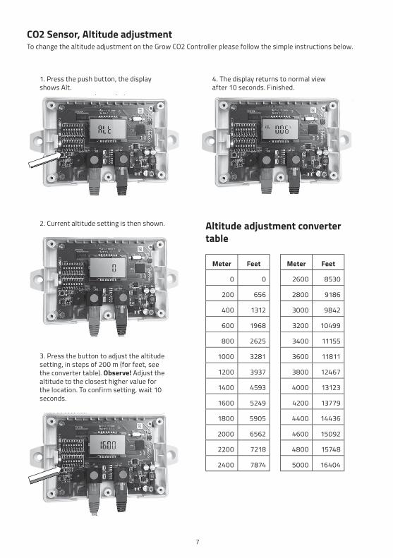
CO2 Sensor, Altitude adjustmentTo change the altitude adjustment on the Grow CO2 Controller please follow the simple instructions below.
2. Current altitude setting is then shown.
4. The display returns to normal view after 10 seconds. Finished.
Altitude adjustment converter table
Meter Feet Meter Feet
0 0 2600 8530
200 656 2800 9186
400 1312 3000 9842
600 1968 3200 10499
800 2625 3400 11155
1000 3281 3600 11811
1200 3937 3800 12467
1400 4593 4000 13123
1600 5249 4200 13779
1800 5905 4400 14436
2000 6562 4600 15092
2200 7218 4800 15748
2400 7874 5000 16404
1. Press the push button, the display shows Alt.
3. Press the button to adjust the altitude setting, in steps of 200 m (for feet, see the converter table). Observe! Adjust the altitude to the closest higher value for the location. To confirm setting, wait 10 seconds.

8
DIP-switch settingsDIP-switch 1: Dip 1-8, Functionality settings
Functionality settings
Dip1 Dip2 Dip3 Dip4 Dip5 Dip6 Dip7 Dip8 DIP-switch 1
Light sensor disabled
OFF1 2 3 4 5 6 7 8
Light sensor enabled
ON1 2 3 4 5 6 7 8
Adaptive CO2-control disabled
OFF1 2 3 4 5 6 7 8
Adaptive CO2-control enabled
ON1 2 3 4 5 6 7 8
Dosage time (at Dip2-OFF) 30 sec
OFF1 2 3 4 5 6 7 8
Dosage time (at Dip2-OFF) 60 sec
ON1 2 3 4 5 6 7 8
Dip4 Not used
Temperature alarm disabled
OFF1 2 3 4 5 6 7 8
Temperature alarm enabled
ON1 2 3 4 5 6 7 8
Celsius OFF1 2 3 4 5 6 7 8
Fahrenheit ON1 2 3 4 5 6 7 8
CO2 control hysteresis 40 ppm
OFF1 2 3 4 5 6 7 8
CO2 control hysteresis 100 ppm
ON1 2 3 4 5 6 7 8
“LOW-indication” disabled
OFF1 2 3 4 5 6 7 8
“LOW-indication” enabled
ON1 2 3 4 5 6 7 8

9
DIP-switch 2: Dip 1, 2 and 8, Functionality settings
Functionality settings Dip1 Dip2 Dip8 DIP-switch 2
Service mode off OFF1 2 3 4 5 6 7 8
Service mode on ON1 2 3 4 5 6 7 8
Automatic calibration disabled
OFF1 2 3 4 5 6 7 8
Automatic calibration enabled
ON1 2 3 4 5 6 7 8
RS485 termination off OFF1 2 3 4 5 6 7 8
RS485 termination on ON1 2 3 4 5 6 7 8

10
DIP-switch 2: Dip 3-7, Communication ID-number
ID- address Dip3 Dip4 Dip5 Dip6 Dip7 DIP-switch 2
ID1 OFF OFF OFF OFF OFF87654321
ID2 ON OFF OFF OFF OFF87654321
ID3 OFF ON OFF OFF OFF87654321
ID4 ON ON OFF OFF OFF87654321
ID5 OFF OFF ON OFF OFF87654321
ID6 ON OFF ON OFF OFF87654321
ID7 OFF ON ON OFF OFF87654321
ID8 ON ON ON OFF OFF87654321
ID9 OFF OFF OFF ON OFF87654321
ID10 ON OFF OFF ON OFF87654321
ID11 OFF ON OFF ON OFF87654321
ID12 ON ON OFF ON OFF87654321
Plug-In Power Supply, SpecificationsType: Model FJ-SW2401000NInput voltage: 100-240V AC, 50/60 Hz, max 0.5 A. Output: 24V DC, max 1.0 AAmbient temperature: 0-40°C (+32°F to +102°F)Dimensions (LxWxD): 82.4 x 44.5 x 36.2 mm / 3.2” x 1.8” x 1.4” + input plug

11
1 2 3 4 5 6 7 8 9 10
ON
Relay 1 Relay 2
Relay 1V- C V+
GreenGreen/White
BrownBrown/White
Relay 2
Jumper settingDIP-Switch settings
From Grow Controller
Solenoid valve
Inside the Solenoidvalve RCB Box
Red LED = Adding CO2V+ V- AL
-1AL
-2SW
+SW
G
NC
-1C
-1N
O-1
NC
-2C
-2N
O-2
Blue Cat5cable from
sensor
Relay 1 Relay 2
Relay 1V- C V+
GreenGreen/White
BrownBrown/White
Relay 2
Remove Jumpers from pins
Power to fan, via relay contact
Fan
ExternalRelay
Fan activation settings
DIP- Switch settings
From CO2 Sensor
Not used
Power to External Relay coil, via relay contact in the 0471 RCB Box. Max ratings: 1A/24V AC/DC
1 2 3 4 5 6 7 8 9 10
ON
V+ V- AL-1
AL-2
SW+
SWG
NC
-1C
-1N
O-1
NC
-2C
-2N
O-2
Blue Cat5cable from
sensor
Inside the 0471RCB Box
Connection diagram: Magnetic valve
Connection diagram: Start fan via External Relay with 0471 RCB Box

Service and maintenance1. Service and maintenance should be performed
only by authorized professional service agents who are familiar with the Grow CO2 Controller and all pertinent safety and service procedures. Contact your representative for the name of the authorized service agent(s) in your area.
2. Since this also is a safety product we recommend that a function check should be performed on the Grow CO2 Controller, by a qualified professional service agent at least once every year.
3. The Grow CO2 Controller has no user serviceable parts. All service work should be performed by an authorized professional agent.
4. NOTE! Any attempt to service the equipment by unauthorized persons or to perform unauthorized modifications will void the warranty.
5. The housing must NEVER be opened by unauthorized personnel.
6. Cleaning is done by use of water on a moistened cloth.
ImportantAll persons responsible for the use and maintenance of this equipment must read and understand the safety and operating information contained in this guide. Installation and service of this equipment should be performed only by professionals. The function of the equipment will be impaired if it is not properly installed.
Important information regarding third party productsThe functionality of LogiCO2’s products are only warranted if connected to LogiCO2’s systems and products. LogiCO2 is not liable for the functionality of any systems if LogiCO2 components or parts are connected to third party products. LogiCO2 permits its products to be connected to external relays controlling ventilation and valves as well as fire alarm panels and building management systems.Subject to typographical errors and change without prior notice.
Manufactured by:
LogiCO2 International ABBox 9097400 92 Gothenburg, Sweden
E-mail: [email protected]: www.logico2.com
© 2021-09-07 R1.0 LogiCO2 HFE1188 EN