Embed Size (px)
Citation preview

Service ManualTrucks
Group 36Fault CodesVehicle ECU
MID 144Volvo or Cummins Engine
VN, VHD VERSION 2
PV776-20 033671


Foreword
The descriptions and service procedures contained in this manual are based on designsand methods studies carried out up to August 2005.
The products are under continuous development. Vehicles and components producedafter the above date may therefore have different specifications and repair methods.When this is believed to have a significant bearing on this manual, supplementaryservice bulletins will be issued to cover the changes.
The new edition of this manual will update the changes.
In service procedures where the title incorporates an operation number, this is areference to an V.S.T. (Volvo Standard Times).
Service procedures which do not include an operation number in the title are for generalinformation and no reference is made to an V.S.T.
Each section of this manual contains specific safety information and warnings whichmust be reviewed before performing any procedure. If a printed copy of a procedure ismade, be sure to also make a printed copy of the safety information and warnings thatrelate to that procedure. The following levels of observations, cautions and warningsare used in this Service Documentation:
Note: Indicates a procedure, practice, or condition that must be followed in order to havethe vehicle or component function in the manner intended.
Caution: Indicates an unsafe practice where damage to the product could occur.
Warning: Indicates an unsafe practice where personal injury or severe damage to theproduct could occur.
Danger: Indicates an unsafe practice where serious personal injury or death could occur.
Volvo Trucks North America, Inc.Greensboro, NC USA
Order number: PV776-20 033671Repl: PV776–TSP196291
© 2005 Volvo Trucks North America, Inc., Greensboro, NC USA
All rights reserved. No part of this publication may be reproduced, stored inretrieval system, or transmitted in any forms by any means, electronic,mechanical, photocopying, recording or otherwise, without the prior writtenpermission of Volvo Trucks North America, Inc..
USA17877


ContentsSpecifications ............................................................. 3
Vehicle ECU ............................................................... 3
Tools .......................................................................... 15Special Tools ............................................................ 15
Troubleshooting ........................................................ 19MID 144 Vehicle Control Unit, Fault Codes .............. 19MID 144 PID 84 Vehicle Speed ................................ 21MID 144 PID 84 Vehicle Speed, Check .................... 23MID 144 PID 91 Accelerator Pedal Position(Percentage) ............................................................. 27MID 144 PID 91 Accelerator Pedal Position(Percentage), Check ................................................. 28MID 144 PID 150 PTO Output .................................. 32MID 144 PID 150 PTO Output, Check ...................... 34MID 144 PID 152 VECU, Number of Resets ............ 36MID 144 PID 191 Output Shaft Speed ..................... 37MID 144 PID 191 Output Shaft Speed, Check ......... 40MID 144 PPID 61 Engine Brake Switch ................... 44MID 144 PPID 61 Engine Brake Switch, Check ....... 45MID 144 PPID 69 Buffered Idle Validation Switch .... 48MID 144 PPID 69 Buffered Idle Validation Switch,Check ....................................................................... 49MID 144 PPID 70 Pedal Switches, Supply ............... 51MID 144 PPID 70 Pedal Switches, Supply, Check ... 52MID 144 PPID 71 Cruise Control and EngineBrake, Switch Supply ................................................ 59MID 144 PPID 71 Cruise Control and EngineBrake, Switch Supply, Check .................................... 61MID 144 PPID 72 Accelerator Pedal and EngineBrake, Sensors Supply ............................................. 69
MID 144 PPID 72 Accelerator Pedal and EngineBrake, Sensors Supply, Check ................................. 70MID 144 PPID 74 VECU Power Supply .................... 77MID 144 PPID 74 Power Supply EECU/VECU,Check ....................................................................... 78MID 144 SID 230 Idle Validation Switch 1 ................ 80MID 144 SID 230 Idle Validation Switch 1, Check .... 81MID 144 SID 231 J1939 Control Link ....................... 83MID 144 SID 240 Program Memory ......................... 85MID 144 SID 243 Cruise Control Set Switch ............ 86MID 144 SID 243 Cruise Control Set Switch, Check 87MID 144 SID 250 J1587/J1708 Information DataLink ........................................................................... 91MID 144 SID 253 Calibration Memory EEPROM ..... 92MID 144 PSID 4 Engine Brake Stalk Lever .............. 93MID 144 PSID 4 Engine Brake Stalk Lever, Check .. 94MID 144 PSID 200 J1939 Control Data LinkInterruption, Engine ECU ......................................... 99MID 144 PSID 202 J1939 Control Data LinkInterruption, Instrument Control Unit ...................... 100MID 144 PSID 204 J1939 Control Data LinkInterruption, Brake Control Unit .............................. 101MID 144 PSID 210 J1939 Control Data LinkInterruption, Lighting Control Module (LCM) .......... 102MID 144 PSID 214 J1939 Control Data LinkInterruption, Bodybuilder Control Unit .................... 103MID 144 SID 231 J1939 Control Link ..................... 104
Operation Numbers
1

2

Group 36 Fault Codes, VECU, MID 144, Volvo or Cummins Engine Specifications
Specifications
Vehicle ECU
Component Locations
W3005048
A17 VECU
PA Connector, PA1 - 30 (green)
PB Connector, PB1 - 30 (blue)
PC Connector (green), J1587/1708 Information Data Link, and J1939 Control Data Link
Note: See corresponding (P)PID/(P)SID for location of components.
3

Group 36 Fault Codes, VECU, MID 144, Volvo or Cummins Engine Specifications
Description of SignalsVECU, measurement box connected between VECU and wiring harness,connector PAPrerequisites:• Measurement box 9998699 and adapter 9813194
connected between VECU connector PA and wiringharness.
• VECU connected.• Ignition key in DRIVE position.• Engine OFF.• Measure voltage using multimeter.
T0008364
B+ = battery voltage
Con-nection
Signal type Measuring points Expected value Other
PA1 Cruise controlSET-/COAST
PA1 - PA12 0 VB+ (SET- active)
PA2 Cruise controlSET+/ACCEL
PA2 - PA12 0 VB+ (SET+ active)
PA3 Cruise control,ON/OFF
PA3 - PA12 0 V (OFF)B+ (ON)
PA4 Fuel priming PA4 - PA12 0 V (OFF)B+ (ON)
VOLVO only
PA5 Brake pedal PA5 - PA12 B+0 V (brake pedal depressed)
PA6 Starting switch,start position
PA6 - PA12 0 VB+ (ignition key in START position)
PA7 Starting switch,preheating position
PA7 - PA12 0 VB+ (ignition key in preheat position)
VOLVO only
PA8 Clutch pedal PA8 - PA12 B+0 V (clutch pedal depressed)
PA9 not used
PA10 not used
PA11 not used
PA12 Groundconnection, VECU
PA12 - ground 0 V
PA13 Supply voltage,control unit
PA13 - PA12 0 V (ignition key in OFF position)B+ (ignition key in DRIVE position)
PA14 Starting switch,drive position
PA14 - PA12 0 V (ignition key in OFF position)B+ (ignition key in DRIVE position)
PA15 not used
PA16 not used
PA17 not used
4

Group 36 Fault Codes, VECU, MID 144, Volvo or Cummins Engine Specifications
Con-nection
Signal type Measuring points Expected value Other
PA18 not used
PA19 Manual fan switch PA19 - PA12 0 VB+ (manual fan switch ON)
PA20 Engine brake,switch no. 1
PA20 - PA12 0 V (ignition key in OFF position)See “Engine Brake Variants” page13 (ignition key in ON position)
PA21 Engine brake,switch no. 2
PA21 - PA12 0 V (ignition key in OFF position)See “Engine Brake Variants” page13 (ignition key in ON position)
PA22 reserved PA22 - PA12
PA23 Idle validationswitch 1
PA23 - PA12 0 VB+ (accelerator pedal depressed)
PA24 Air conditioning,status switch
PA24 - PA12 0 V (no fan request from A/C)B+ (fan requested by A/C)
PA25 not used
PA26 not used
PA27 not used
PA28 not used
PA29 Power Take-Off,PTO switch
PA29 - PA12 0 V (switch OFF)B+ (switch ON)
VOLVO only
PA30 Cruise control,RESUME
PA30 - PA12 0 V (RESUME inactive)B+ (RESUME active)
5

Group 36 Fault Codes, VECU, MID 144, Volvo or Cummins Engine Specifications
VECU, measurement box connected between VECU and wiring harness,connector PBPrerequisites:• Measurement box 9998699 and adapter 9998533
connected between VECU connector PB and wiringharness.
• Measurement box 9998699 and adapter 9813194connected between VECU connector PA and wiringharness.
• VECU connected.• Ignition key in DRIVE position.• Engine OFF.• Measure voltage using multimeter.
T0008363
B+ = battery voltage
Con-nection
Signal type Measuring points Expected value Other
PB1 not used
PB2 not used
PB3 Idle validationswitch signal toEECU (redundant)
PB3 - PA12 0 V (accelerator pedal depressed)4.0 - 6.0 V (accelerator pedal at idle)
Cummins only
PB4 not used
PB5 Voltage supply:
• Cruise controlswitch
• Engine brakeswitch
PB5 - PA12 ≈ B+
PB6 Vehicle speedsensor (+)
PB6 - PB20 0.3 - 9.5 V Measurement requiresthat the output shaft fromthe gearbox is rotating.Measure the voltage ofthe signal’s minimum andmaximum values.
PB7 not used
PB8 Accelerator pedal,position
PB8 - PA12 0.4 - 0.6 V (no acceleration)2.6 - 3.8 V (full acceleration)3.0 - 4.4 V (kickdown)
PB9 not used
PB10 Voltage supply:
• Acceleratorpedal sensor
• Engine brakestalk switch
PB10 - PA12 4.7 - 5.3 V Engine brake stalk switch- used only for CumminsEBR-CBJ6
PB11 Parking brake,status
PB11 - PA12 B+ (parking brake released)0 V (parking brake applied)
PB12 not used
PB13 not used
6

Group 36 Fault Codes, VECU, MID 144, Volvo or Cummins Engine Specifications
Con-nection
Signal type Measuring points Expected value Other
PB14 not used
PB15 Relay voltagesupply,
• VECU, EMS(Volvo)
• VECU(Cummins)
PB15 - PA12 B+ (ignition key in OFF position)0 - 1 V (ignition key in DRIVEposition)
PB16 PTO output PB16 - PA12 B+ (inactive)0 V (active)
VOLVO only
PB17 Buffered idlevalidation switch
PB17 - PA12 0 VB+ (accelerator pedal depressed)
VOLVO only
PB18 not used
PB19 Voltage supply:
• Pedal switches
PB19 - PA12 ≈ B+
PB20 Vehicle speedsensor (-)
PB20 - PB6 0.3 - 9.5 V Measurement requiresthat the output shaft fromthe gearbox is rotating.Measure the voltage ofthe signal’s minimum andmaximum values.
PB21 not used
PB22 Ground connection:
• Acceleratorpedal
• Engine brakestalk switch
PB22 - PA12 0 V Engine brake stalk switch- used only for CumminsEBR-CBJ6
PB23 not used
PB24 Engine brake stalkswitch positionsensor
PB24 - PA12 0.3 - 0.7 V (pos 1)1.0 - 1.6 V (pos 2)1.7 - 2.5 V (pos 3)2.3 - 3.5 V (pos 4)2.9 - 4.4 V (pos 5)3.6 - 5.4 V (pos 6)
Cummins ISX withEBR-CBJ6 only; see“Engine Brake Variants”page 13.
PB25 not used
PB26 not used
PB27 Brake pressureswitch
PB27 - PA12 B+ (brake pedal released)0 V (brake pedal depressed)
PB28 not used
PB29 not used
PB30 not used
7
Group 36 Fault Codes, VECU, MID 144, Volvo or Cummins Engine Specifications
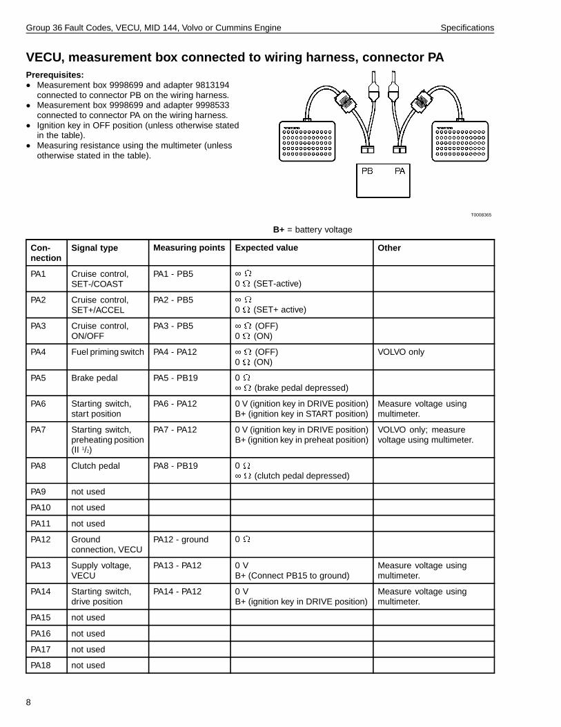
VECU, measurement box connected to wiring harness, connector PAPrerequisites:• Measurement box 9998699 and adapter 9813194
connected to connector PB on the wiring harness.• Measurement box 9998699 and adapter 9998533
connected to connector PA on the wiring harness.• Ignition key in OFF position (unless otherwise stated
in the table).• Measuring resistance using the multimeter (unless
otherwise stated in the table).
T0008365
B+ = battery voltage
Con-nection
Signal type Measuring points Expected value Other
PA1 Cruise control,SET-/COAST
PA1 - PB5 ∞0 (SET-active)
PA2 Cruise control,SET+/ACCEL
PA2 - PB5 ∞0 (SET+ active)
PA3 Cruise control,ON/OFF
PA3 - PB5 ∞ (OFF)0 (ON)
PA4 Fuel priming switch PA4 - PA12 ∞ (OFF)0 (ON)
VOLVO only
PA5 Brake pedal PA5 - PB19 0∞ (brake pedal depressed)
PA6 Starting switch,start position
PA6 - PA12 0 V (ignition key in DRIVE position)B+ (ignition key in START position)
Measure voltage usingmultimeter.
PA7 Starting switch,preheating position(II 1/2)
PA7 - PA12 0 V (ignition key in DRIVE position)B+ (ignition key in preheat position)
VOLVO only; measurevoltage using multimeter.
PA8 Clutch pedal PA8 - PB19 0∞ (clutch pedal depressed)
PA9 not used
PA10 not used
PA11 not used
PA12 Groundconnection, VECU
PA12 - ground 0
PA13 Supply voltage,VECU
PA13 - PA12 0 VB+ (Connect PB15 to ground)
Measure voltage usingmultimeter.
PA14 Starting switch,drive position
PA14 - PA12 0 VB+ (ignition key in DRIVE position)
Measure voltage usingmultimeter.
PA15 not used
PA16 not used
PA17 not used
PA18 not used
8
Group 36 Fault Codes, VECU, MID 144, Volvo or Cummins Engine Specifications
Con-nection
Signal type Measuring points Expected value Other
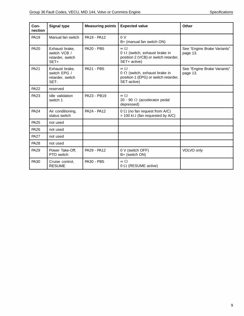
PA19 Manual fan switch PA19 - PA12 0 VB+ (manual fan switch ON)
PA20 Exhaust brake,switch VCB /retarder, switchSET+
PA20 - PB5 ∞0 (switch, exhaust brake inposition 2 (VCB) or switch retarder,SET+ active)
See “Engine Brake Variants”page 13.
PA21 Exhaust brake,switch EPG /retarder, switchSET-
PA21 - PB5 ∞0 (switch, exhaust brake inposition 1 (EPG) or switch retarder,SET-active)
See “Engine Brake Variants”page 13.
PA22 reserved
PA23 Idle validationswitch 1
PA23 - PB19 ∞20 - 90 (accelerator pedaldepressed)
PA24 Air conditioning,status switch
PA24 - PA12 0 (no fan request from A/C)> 100 k (fan requested by A/C)
PA25 not used
PA26 not used
PA27 not used
PA28 not used
PA29 Power Take-Off,PTO switch
PA29 - PA12 0 V (switch OFF)B+ (switch ON)
VOLVO only
PA30 Cruise control,RESUME
PA30 - PB5 ∞0 (RESUME active)
9

Group 36 Fault Codes, VECU, MID 144, Volvo or Cummins Engine Specifications
VECU, measurement box connected to wiring harness, connector PBPrerequisites:• Measurement box 9998699 and adapter 9998533
connected to connector PB on the wiring harness.• Measurement box 9998699 and adapter 9813194
connected to connector PA on the wiring harness.• Ignition key in OFF position (unless otherwise stated
in the table).• Measure resistance using multimeter (unless otherwise
stated in the table).
T0008365
B+ = battery voltage
Connec-tion
Signal type Measuring points Expected value Other
PB1 not used
PB2 not used
PB3 Idle validationswitch signal toEECU (redundant)
Cummins only; no relevantmeasurement.
PB4 not used
PB5 Voltage supply:
• Switch cruisecontrol
• Switch exhaustbrake/retarder(SET+/-)
1 PB5 - PA1
2 PB5 - PA2
3 PB5 - PA3
4 PB5 - PA20
5 PB5 - PA21
6 PB5 - PA30
1 ∞0 (SET-active)
2 ∞0 (SET+ active)
3 ∞ (OFF)0 (ON)
4 See “Engine Brake Variants”page 13
5 See “Engine Brake Variants”page 13
6 ∞0 (RESUME active)
PB6 Vehicle speedsensor
PB6 - PB20 2.0 - 4.0 k (magnetic VSS) Verify VSS installed; with auto trans
(Autoshift, Lightning, Freedom Line),
VECU might receive VSS info over
datalink instead.
PB7 not used
PB8 Accelerator pedal,position
PB8 - PB22¹ 1.0 - 2.0 k (no acceleration)
PB9 not used
10

Group 36 Fault Codes, VECU, MID 144, Volvo or Cummins Engine Specifications
Connec-tion
Signal type Measuring points Expected value Other
PB10 Voltage supply:
• Acceleratorpedal sensor
• Engine brakestalk switch
PB10 - PB22 Measurement at acceleratorpedal¹:3.2 - 4.8 kMeasurement at engine brakestalk switch²:1.7 - 2.5 k (pos 1)1.3 - 2.0 k (pos 2)1.1 - 1.7 k (pos 3)0.9 - 1.4 k (pos 4)0.8 - 1.2 k (pos 5)0.7 - 1.1 k (pos 6)
See “Engine Brake Variants”page 13.
PB11 Parking brake,status
PB11 - PA12 ∞ (parking brake released)0 (parking brake applied)
PB12 not used
PB13 not used
PB14 not used
PB15 Relay, voltagesupply
• VECU, EMS(VOLVO)
• VECU,(Cummins)
PB15 - PA12 B+0 V (ground PB15, and listen forrelay clicking sound)
Ignition key in DRIVE position
PB16 PTO output PB16 - PA12 Ignition key in DRIVE position,switch PTO active, connect PB 16to ground, listen for clicking soundfrom solenoid valve
VOLVO only
PB17 Buffered idlevalidation switch
PB17 - PA12 2.3 - 3.5 k VOLVO only
PB18 not used
PB19 Voltage supply:
• Pedal switches1 PB19 - PA5
2 PB19 - PA8
3 PB19 - PA23
1 0∞ (brake pedal depressed)
2 0∞ (clutch pedal depressed)
3 ∞20 - 90 (accelerator pedaldepressed)
PB20 Vehicle speedsensor (-)
PB20 - PB6 2.0 - 4.0 k (magnetic VSS) Verify VSS installed; with auto trans
(Autoshift, Lightning, Freedom Line),
VECU might receive VSS info over
datalink instead.
PB21 not used
11

Group 36 Fault Codes, VECU, MID 144, Volvo or Cummins Engine Specifications
Connec-tion
Signal type Measuring points Expected value Other
PB22 Groundconnection:
• Acceleratorpedal
• Engine brakestalk switchposition sensor(Cummins ISX)
1 PB22 - PB8¹
2 PB22 - PB10
1 1.0 - 2.0 k (no acceleration)2 Measurement at accelerator
pedal¹:3.2 - 4.8 kMeasurement at engine brakestalk switch²:1.7 - 2.5 k (pos 1)1.3 - 2.0 k (pos 2)1.1 - 1.7 k (pos 3)0.9 - 1.4 k (pos 4)0.8 - 1.2 k (pos 5)0.7 - 1.1 k (pos 6)
See “Engine Brake Variants”page 13
PB23 not used
PB24 Engine brake stalkswitch positionsensor
PB24 - PB22² 1.0 - 1.4 k (pos 1)0.9 - 1.3 k (pos 2)0.8 - 1.2 k (pos 3)0.8 - 1.1 k (pos 4)0.7 - 1.1 k (pos 5)0.7 - 1.0 k (pos 6)
Cummins EBR-CBJ6 only
PB25 not used
PB26 not used
PB27 Brake pressureswitch
PB27 - PA12 3.5 V - B+ (brake pedal released)0 V (brake pedal depressed)
Measure voltage usingmultimeter.
PB28 not used
PB29 not used
PB30 not used
Table Notes1 Connector to engine brake stalk switch disconnected.2 Connector to accelerator pedal disconnected.
12

Group 36 Fault Codes, VECU, MID 144, Volvo or Cummins Engine Specifications
Engine Brake Variants
EBR VariantSwitch
Pos
Stalk
Pos
Voltage
(A)
PA20 -
PA12
Voltage
(A)
PA21 -
PA12
Voltage (A)
PB24 - PA12
Resistance
(B)
PA20 - PB5
Resistance
(B)
PA21 - PB5
Resistance
(B)
PB24 - PB22
(1)
% EBR
(Parameter
Code)
“Notes”page
13
D12D
(EBR-EPG)
OFF
ONn/a
0 V
0 V
0 V
B+n/a
∞
∞
∞
0 n/a n/a
D12D
(EBR-VEB)
OFF
LOW
HIGH
n/a
0 V
0 V
B+
0 V
B+
B+
n/a
∞
∞
0
∞
0
0
n/a n/a
ISL/ISC
(EBR-EXH)
OFF
ONn/a
0 V
0 V
0 V
B+n/a
∞
∞
∞
0 n/a
0 (ATC)
100 (ATD)(2)
ISL
(EBR-CBJ2)
OFF
LOW
HIGH
n/a
0 V
0 V
B+
0 V
B+
0 V
n/a
∞
∞
0
∞
0
∞
n/a
0 (ATC)
50 (ATD)
100 (ATE)
(2)
ISX
(EBR-CBJ3)
OFF
LOW
MED
HIGH
n/a
0 V
B+
0 V
B+
0 V
0 V
B+
B+
n/a
∞
0
∞
0
∞
∞
0
0
n/a
0 (ATC)
33 (ATE)
66 (ATD)
100 (ATF)
(2)
ISX
(EBR-
CBJ6; with
6-position
stalk lever)
OFF
ON
ON
ON
ON
ON
ON
ANY
1
2
3
4
5
6
0 V
B+
B+
B+
B+
B+
B+
n/a
—
0.3 - 0.7 V
1.0 - 1.6 V
1.7 - 2.5 V
2.3 - 3.5 V
2.9 - 4.4 V
3.6 - 5.4 V
∞
0
0
0
0
0
0
n/a
—
1.0 - 1.4 k
0.9 - 1.3 k
0.8 - 1.2 k
0.8 - 1.1 k
0.7 - 1.1 k
0.7 - 1.0 k
0
17 (ATC)
33 (ATD)
50 (ATE)
67 (ATF)
83 (ATG)
100 (ATH)
(2) (3)
Notes(A) Voltage measurements (VECU connected)(B) Resistance measurements (VECU disconnected)(1) Connector to accelerator pedal disconnected(2) Parameter codes ATC through ATH
correspond to parameter namesCUMMINS_engine brake_SWITCH_POS1through _POS6, and are used by the VECU torelate engine brake switch input(s) to the requested
engine brake % sent to the engine. These are Level3 Programmable by the customer using VCADS Pro(with network connection).
(3) EBR function is 0% whenever ON/OFF switch isOFF. When ON/OFF switch is ON, EBR function % isdetermined by stalk position.
13

14

Group 36 Fault Codes, VECU, MID 144, Volvo or Cummins Engine Tools
Tools
Special ToolsThe following special tools are used to carry out fault tracing of components. Forordering instructions for special tools, refer to tool information, group 08.
999001462-pin cable adapter
9990020Cruise control switch adapter
9990062Extension cable (for 9990014)
9990151Adapter, vehicle speed sensor
9998533Adapter between VECU, connector PB,
and measurement box
9998534Adapter for DIN connector
9990008Set of testpins
9998699Measurement box 62-unit
9998604Adapter
15

Group 36 Fault Codes, VECU, MID 144, Volvo or Cummins Engine Tools
88890016Accelerator pedal switch
Overlay Part Numbers
85104406Overlay (used with adapter 9998533)
85104407Overlay (used with adapter 9813194)
85104409Overlay (used with adapter 9998604)
85108489Overlay (Used with adapter 88890016)
16

Group 36 Fault Codes, VECU, MID 144, Volvo or Cummins Engine Tools
Other Special Equipment
J39200Multimeter
9813194Adapter between VECU, connector PA,
and measurement box 9998699
17

18
Group 36 Fault Codes, VECU, MID 144, Volvo or Cummins Engine Troubleshooting
Troubleshooting
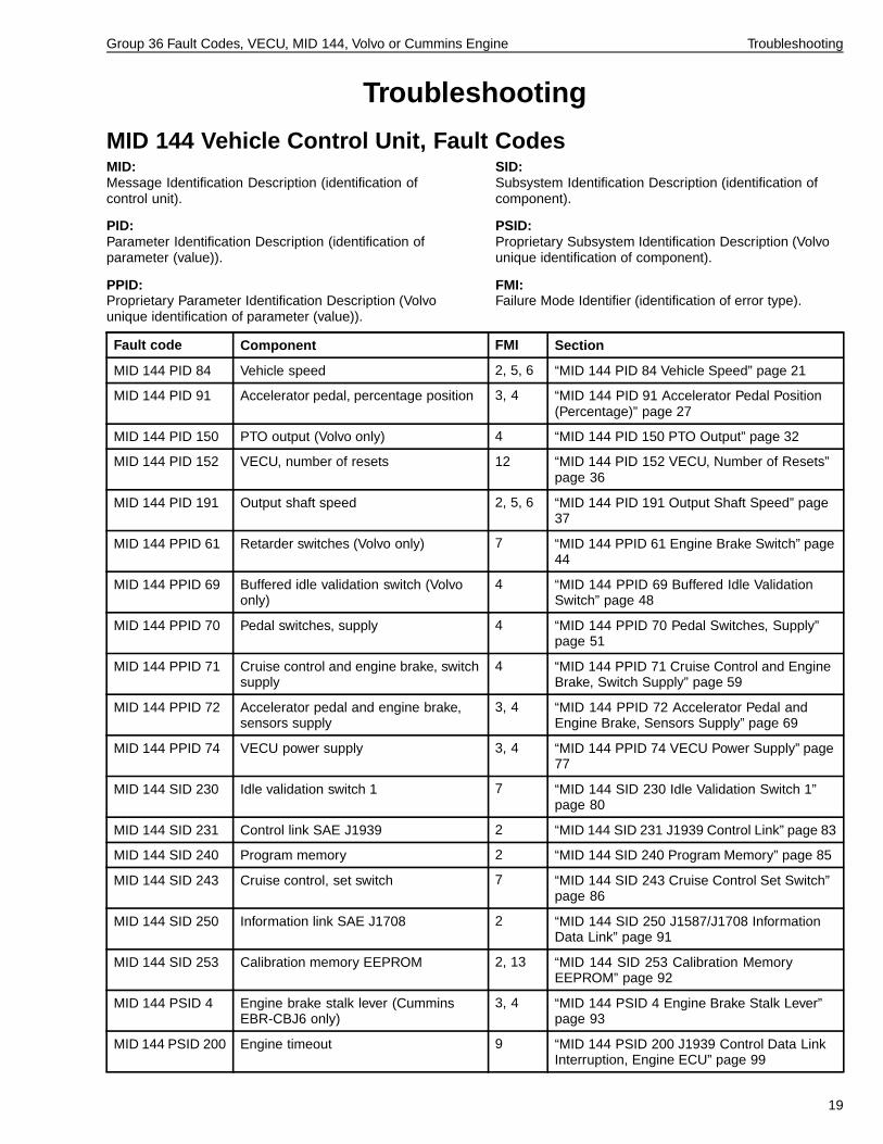
MID 144 Vehicle Control Unit, Fault CodesMID:Message Identification Description (identification ofcontrol unit).
PID:Parameter Identification Description (identification ofparameter (value)).
PPID:Proprietary Parameter Identification Description (Volvounique identification of parameter (value)).
SID:Subsystem Identification Description (identification ofcomponent).
PSID:Proprietary Subsystem Identification Description (Volvounique identification of component).
FMI:Failure Mode Identifier (identification of error type).
Fault code Component FMI Section
MID 144 PID 84 Vehicle speed 2, 5, 6 “MID 144 PID 84 Vehicle Speed” page 21
MID 144 PID 91 Accelerator pedal, percentage position 3, 4 “MID 144 PID 91 Accelerator Pedal Position(Percentage)” page 27
MID 144 PID 150 PTO output (Volvo only) 4 “MID 144 PID 150 PTO Output” page 32
MID 144 PID 152 VECU, number of resets 12 “MID 144 PID 152 VECU, Number of Resets”page 36
MID 144 PID 191 Output shaft speed 2, 5, 6 “MID 144 PID 191 Output Shaft Speed” page37
MID 144 PPID 61 Retarder switches (Volvo only) 7 “MID 144 PPID 61 Engine Brake Switch” page44
MID 144 PPID 69 Buffered idle validation switch (Volvoonly)
4 “MID 144 PPID 69 Buffered Idle ValidationSwitch” page 48
MID 144 PPID 70 Pedal switches, supply 4 “MID 144 PPID 70 Pedal Switches, Supply”page 51
MID 144 PPID 71 Cruise control and engine brake, switchsupply
4 “MID 144 PPID 71 Cruise Control and EngineBrake, Switch Supply” page 59
MID 144 PPID 72 Accelerator pedal and engine brake,sensors supply
3, 4 “MID 144 PPID 72 Accelerator Pedal andEngine Brake, Sensors Supply” page 69
MID 144 PPID 74 VECU power supply 3, 4 “MID 144 PPID 74 VECU Power Supply” page77
MID 144 SID 230 Idle validation switch 1 7 “MID 144 SID 230 Idle Validation Switch 1”page 80
MID 144 SID 231 Control link SAE J1939 2 “MID 144 SID 231 J1939 Control Link” page 83
MID 144 SID 240 Program memory 2 “MID 144 SID 240 Program Memory” page 85
MID 144 SID 243 Cruise control, set switch 7 “MID 144 SID 243 Cruise Control Set Switch”page 86
MID 144 SID 250 Information link SAE J1708 2 “MID 144 SID 250 J1587/J1708 InformationData Link” page 91
MID 144 SID 253 Calibration memory EEPROM 2, 13 “MID 144 SID 253 Calibration MemoryEEPROM” page 92
MID 144 PSID 4 Engine brake stalk lever (CumminsEBR-CBJ6 only)
3, 4 “MID 144 PSID 4 Engine Brake Stalk Lever”page 93
MID 144 PSID 200 Engine timeout 9 “MID 144 PSID 200 J1939 Control Data LinkInterruption, Engine ECU” page 99
19

Group 36 Fault Codes, VECU, MID 144, Volvo or Cummins Engine Troubleshooting
Fault code Component FMI Section
MID 144 PSID 202 Instrument timeout 9 “MID 144 PSID 202 J1939 Control Data LinkInterruption, Instrument Control Unit” page 100
MID 144 PSID 204 ABS/EBS timeout 9 “MID 144 PSID 204 J1939 Control Data LinkInterruption, Brake Control Unit” page 101
MID 144 PSID 210 LCM timeout 9 “MID 144 PSID 210 J1939 Control Data LinkInterruption, Lighting Control Module (LCM)”page 102
MID 144 PSID 214 BBM timeout (VOLVO only, vehiclesequipped with BBM)
9 “MID 144 PSID 214 J1939 Control Data LinkInterruption, Bodybuilder Control Unit” page103
FMI TableSAE standard
FMI Display text SAE text
0 Value too high Data valid, but above normal operating range.
1 Value too low Data valid, but under normal operating range
2 Incorrect data Intermittent or incorrect data.
3 Electrical faults Abnormally high voltage or short circuit to higher voltage.
4 Electrical faults Abnormally low voltage or short circuit to lower voltage.
5 Electrical faults Abnormally low current or open circuit.
6 Electrical faults Abnormally high current or short circuit to ground.
7 Mechanical fault Incorrect response from mechanical system.
8 Mech. or electrical faults Abnormal frequency.
9 Communication fault Abnormal updating rate.
10 Mech. or electrical faults Abnormally large variations.
11 Unknown fault Unidentifiable error.
12 Component fault Faulty unit or component.
13 Incorrect calibration Calibration values outside the limits.
14 Unknown fault Special instructions.
15 Unknown fault Reserved for future use.
20

Group 36 Fault Codes, VECU, MID 144, Volvo or Cummins Engine Troubleshooting
MID 144 PID 84 Vehicle Speed
W3006058
W3006059
GeneralThe Vehicle Speed Signal arrives at the VECU from oneof three sources, depending on vehicle / transmissionconfiguration:
• Eaton-type Vehicle Speed Sensor (VSS)• Automated Transmission without extra sensor• Allison Transmission
In all cases, the origin of the Vehicle Speed Signalis a VSS sensor in the output shaft (tailshaft) of thetransmission.
Component: A17, VECU; B68 speedometer sensor.
21

Group 36 Fault Codes, VECU, MID 144, Volvo or Cummins Engine Troubleshooting
Fault code
FMI 2Intermittent or incorrect data.
Conditions for fault code:• The VECU can receive vehicle speed information
over the J1939 Control Data Link from certaintransmissions. This FMI will occur if the VECU isexpecting such data but does not receive it.
Note: First read and correct fault codes from thetransmission ECU, if applicable.
Possible cause:• Fault in wiring harness, control link.• Fault in vehicle speed sensor or VSS wiring to
transmission ECU.
Reaction from VECU:• Fault code is set.• Yellow lamp is requested.
Noticeable external symptom:• Yellow lamp lights up.• No vehicle speed in gauge.• No PTO or cruise control.
Action:• Troubleshoot J1939 Control Data Link; refer to Service
Information, group 37.• “MID 144 PID 84 Vehicle Speed, Check” page 23.
FMI 5Abnormally low current or open circuit.
Conditions for fault code:• If the VECU registers a current lower than 90 µA on
any of the signal wires from the speed sensor theVECU interprets this as a fault and a fault code is set.
Possible cause:
• Poor contact, sensor connection.
• Switch resistance and oxidation.
• Break, signal wire.
• Fault in sensor.
Reaction from the VECU:
• Yellow lamp lights up.
Noticeable external symptom:
• No vehicle speed on gauge.
• No PTO.
• No cruise control.
Action:
• “MID 144 PID 84 Vehicle Speed, Check” page 23.
FMI 6Abnormally high current or short circuit.
Conditions for fault code:• If the VECU registers a current higher than 140 µA
on any of the signal wires from the speed sensor, theVECU interprets this as a fault and a fault code is set.
Possible cause:
• Signal wire short-circuited to higher voltage.
• Signal wire short-circuited to ground.
• Signal wires short-circuited to each other.
• Fault in sensor.
Reaction from the VECU:
• Yellow lamp lights up.
Noticeable external symptom:
• No vehicle speed on gauge.
• No PTO.
• No cruise control.
Action:
• Troubleshoot J1939 Control Data Link; refer to ServiceInformation, group 37.
• “MID 144 PID 84 Vehicle Speed, Check” page 23.
22

Group 36 Fault Codes, VECU, MID 144, Volvo or Cummins Engine Troubleshooting
3649-21-03-08MID 144 PID 84 Vehicle Speed, Check
Special tools: 9990151, 9998533, 9998699Other special equipment: J39200
NOTE!• Read off the other fault codes for the VECU,
speedometer, and brake control unit.• Switch off the current in the vehicle before the
connectors are disconnected.• Check for loose connections, switch resistance, and
oxidation. For information concerning fault tracing ofwires and connectors, refer to Service Information,group 37.
Tests Using PC ToolThe following tests are useful for closely examining thecomponent’s function:
• “Cruise control switch, test”
The test allows you to read the speed signal from theVECU.
Determination of Vehicle SpeedSensor ConfigurationThe appropriate check of the system will depend on theconfiguration of the Vehicle Speed sensor and circuits.Use the following information to determine which systemthe vehicle has:
• Eaton-Type Vehicle Speed Sensor
Use this check whenever FMI 5 or 6 is present.This type of Vehicle Speed Sensor (VSS) will befound on the tailshaft of manual transmissions.It may also be found on some automatedtransmissions (Eaton Autoshift, Eaton Lightning)when two VSS are present in the tailshaft - oneVSS will be wired directly to the TransmissionECU, the other will be wired to the VECU(circuits 550/551).
• Automated Transmission without Extra Sensor
If only one VSS is found on an automatedtransmission (Eaton Autoshift, Eaton Lightning)the VECU is receiving Outputshaft Speedinformation from the Transmission ECU overthe J1939 datalink.All Meritor / ZF FreedomLine transmissions fallinto this category.
• Allison Transmission
Use this section if the vehicle is equipped with anAllison MD or HD transmission.
23

Group 36 Fault Codes, VECU, MID 144, Volvo or Cummins Engine Troubleshooting
Measurement at componentconnector to VECUNote: Faults in the wiring harness to the VECUcan damage the component. Therefore, a check ofthe component should also be made if any of themeasurement values deviate.
• Eaton-type Vehicle Speed Sensor (VSS)
For this type of VSS, 3 checks can be performed:
1 Prerequisites:
• Ignition key in OFF position.• Measurement box inserted at VECU
(disconnected at VECU side).• Vehicle Speed Sensor at transmission connected.• Measure resistance, harness side of PB6 – PB20,
“looking toward” VSS.•
Measuring points Expected value
PB6 - PB20 2.0 - 4.0 k
2 Prerequisites:
• Ignition key in OFF position.• Measurement box inserted at VECU
(disconnected at VECU side).• Vehicle Speed Sensor at transmission
disconnected.• Make sure PB6 and PB20 are not shorted to
ground, power, or each other.•
Measuring points Expected value
PB6 - PB20 OL
PB6 - ground OL
PB20 - ground OL
3 Prerequisites:
• Ignition key in ON position.• Measurement box inserted at VECU (connected
at VECU).• Vehicle Speed Sensor at transmission connected.• Vehicle must be stationary.• Measure voltage across PB6 – PB20.
Measuring points Expected value
PB6 - PB20 1.25 - 1.75 Vdc (average)varying between approx. 1.0 and 2.0 V
24

Group 36 Fault Codes, VECU, MID 144, Volvo or Cummins Engine Troubleshooting
• Automated Transmission without Extra Sensor
1 If two Vehicle Speed Sensors (VSS) are presentin the transmission’s tailshaft and the PID 84fault code set by the VECU is FMI 5 or 6, usethe troubleshooting for the Eaton-type VehicleSpeed Sensor (above).
2 If only one VSS is present in the tailshaft (or ifnone are visible, as is the case with the Meritor /ZF FreedomLine), then the VECU is receiving itsinformation over the J1939 Control Data Link.Another way to tell that the VECU is receiving theinformation over the Data Link is by the FMI thatthe VECU is using. For example, if the fault codeis PID 84 FMI 2, this indicates that the VECU isexpecting the data over the J1939 Control DataLink but is not receiving it.
3 In these cases, troubleshoot any fault codes in thetransmission ECU first. If the trouble remains,refer to troubleshooting information for the SAEJ1939 Control Data Link, group 37.
• Allison Transmission
1 The Vehicle Speed information from AllisonTransmissions can be obtained one of two ways:
• A hardwire connection from the Allison ECU(Black connector, pin 30, circuit A215) tothe VECU (PB6, circuit 550). This signalis a square-wave reproduction of the VSSlocated in the Allison’s tailshaft.
• Over the J1939 Control Data Link. (NOTE:even if obtaining the information over theData Link, the hardwire connection maystill be in place.)
In either case, troubleshoot any fault codes in theAllison transmission ECU first.
2 If the PID 84 fault code in the VECU is FMI 2, thisindicates that the VECU is configured to receivethe VSS information over the J1939 ControlData Link. If the problem remains, refer totroubleshooting information for the SAE J1939Control Data Link, group 37.
3 If FMI 2 is not indicated, or there are no fault codespresent in the VECU but a speed-related problemstill exists, troubleshoot the hardwire connectionbetween the Allison Transmission ECU and theVECU. Refer to Service Information, group 37.
25

Group 36 Fault Codes, VECU, MID 144, Volvo or Cummins Engine Troubleshooting
Check of ComponentNote: Faults in the component can be caused by faultsin the wiring harness of the control unit. Therefore, acheck of the wiring harness should also be made beforeconnecting a new component.
• Eaton-Type Vehicle Speed Sensor (VSS)
For the Eaton-type VSS, one check can be performedat the VSS:
Prerequisites:• Vehicle Speed Sensor at transmission disconnected.• Measure resistance of sensor using tool 9990151.
Measuring points Expected value
A - B 2.0 - 4.0 k
• Automated Transmission without Extra Sensor
No relevant measurements; refer to the appropriateservice literature for the transmission manufacturer.
• Allison Transmission
No relevant measurements; refer to the appropriateservice literature for the transmission manufacturer.
VerificationUsing the PC tool, check that the fault has been corrected(see “Tests Using PC Tool” page 23).
26

Group 36 Fault Codes, VECU, MID 144, Volvo or Cummins Engine Troubleshooting
MID 144 PID 91 Accelerator Pedal Position (Percentage)
W3006772
W3006776
General InformationComponent: B25 sensor, accelerator pedal; A17, VECU
Fault Codes
FMI 3Abnormally high voltage or short circuit to higher voltage.
Conditions for fault code:• If the VECU receives a signal from the sensor that is
higher than 4.3 V, the control unit interprets this as afault and a fault code is set.
Possible cause:• Open circuit, ground cable.• Signal wire short-circuited to higher voltage.• Faulty sensor.• Idle switch 1 faulty.• Switch resistance and oxidation.
Reaction from VECU:• Fault code is set.• Yellow lamp is requested.
Noticeable external symptom:• Yellow lamp lights up.• Engine/system does not respond to full acceleration.
Action:• “MID 144 PID 91 Accelerator Pedal Position
(Percentage), Check” page 28.
FMI 4Abnormally low voltage or short circuit to lower voltage.
Conditions for fault code:• If the VECU receives a signal from the sensor that is
lower than 0.4 V, the control unit interprets this as afault and a fault code is set.
Possible cause:• Open circuit, supply cable.• Open circuit, signal cable.• Signal wire short-circuited to ground.• Faulty sensor.• Switch resistance and oxidation.
Reaction from VECU:• Fault code is set.• Yellow lamp is requested.
Noticeable external symptom:• Yellow lamp lights up.• Engine/system does not respond to full acceleration.
Action:• “MID 144 PID 91 Accelerator Pedal Position
(Percentage), Check” page 28.
27

Group 36 Fault Codes, VECU, MID 144, Volvo or Cummins Engine Troubleshooting
3649-21-03-09MID 144 PID 91 Accelerator Pedal Position (Percentage), Check
Special tools: 8510848, 99998533, J39192,88890016, 9998699Other special equipment: J39200
NOTE!• Read off the other fault codes for the VECU.
• Switch off the current in the vehicle before theconnectors are disconnected.
• Check for loose connections, switch resistance, andoxidation. For information concerning fault tracing ofwires and connectors, refer to Service Information,group 37.
Tests Using PC ToolThe following tests are useful to check componentfunction:
• Accelerator pedal switches and sensors, test• MID 144, pinout test
Measurement at the component’sconnector to VECUNote: Faults in the wiring harness to the VECUcan damage the component. Therefore, a check ofthe component should also be made if any of themeasurement values deviate.
Ground wire
1
Prerequisites:• Connector to the accelerator pedal sensor
disconnected.• Connector to engine brake switch disconnected (if
equipped).• Measure resistance using multimeter.• VECU connected.• Ignition key in OFF position.• Measurement to the VECU.
Measuring points Expected value
4 - alt ground 0
88890016J39200
28

Group 36 Fault Codes, VECU, MID 144, Volvo or Cummins Engine Troubleshooting
Supply wire
2
Prerequisites:• Connector to the accelerator pedal sensor
disconnected.• Connector to engine brake switch disconnected (if
equipped).• Measure voltage using multimeter.• VECU connected.• Ignition key in DRIVE position.• Measurement to the VECU.
Measuring points Expected value
6 - 4 4.3 - 6.5 V
88890016J39200
Signal wire
3
Prerequisites:• Connector to the accelerator pedal sensor
disconnected.• Connector to engine brake switch disconnected (if
equipped).• Measure resistance using multimeter.• VECU connected.• Ignition key in OFF position.• Measurement to the VECU.
Measuring points Expected value
5 - 4 80 - 120 k
88890016J39200
Wiring harness
4Check the wiring harness; refer to Service Information,group 37.
29

Group 36 Fault Codes, VECU, MID 144, Volvo or Cummins Engine Troubleshooting
Check of componentNote: Faults in the component can be caused by faultsin the wiring harness of the control unit. Therefore, acheck of the wiring harness should also be made beforeconnecting a new component.
Accelerator pedal sensor
1
Prerequisites:• Connector to the accelerator pedal sensor
disconnected.• Measurement box with adapter connected to the
accelerator pedal sensor.• Measure resistance using multimeter.• Ignition key in OFF position.• Measurement at the accelerator pedal sensor.
Measuring points Expected value
6 - 4 3.2 - 4.8 k
6 - 5 1.0 - 2.0 k (no acceleration)
88890016J39200
Check of subsystem
Ground wire
1
Prerequisites:• Measurement box with adapter connected between
VECU connector PB (blue) and wiring harness.• Measuring the resistance using the multimeter.• VECU connected.• Ignition key in OFF position.
Measuring points Expected value
PB22 - ground 0
9998533, 9998699J39200
30

Group 36 Fault Codes, VECU, MID 144, Volvo or Cummins Engine Troubleshooting
Supply wire
2
Prerequisites:• Measurement box with adapter connected between
VECU connector PB (blue) and wiring harness.• Measure voltage using multimeter.• VECU connected.• Ignition key in DRIVE position.
Measuring points Expected value
PB10 - PB22 4 - 6 V
9998533, 9998699J39200
Signal wire
3
Prerequisites:• Measurement box with adapter connected between
VECU connector PB (blue) and wiring harness.• Measure voltage using multimeter.• VECU connected.• Ignition key in DRIVE position.
Measuring points Expected value
PB8 - PB22 0.4 - 0.6V (no acceleration)2.6 - 3.8 V (full acceleration)
9998533, 9998699J39200
VerificationUsing the PC tool, check that the fault has been corrected(see “Tests Using PC Tool” page 28).
31
Group 36 Fault Codes, VECU, MID 144, Volvo or Cummins Engine Troubleshooting
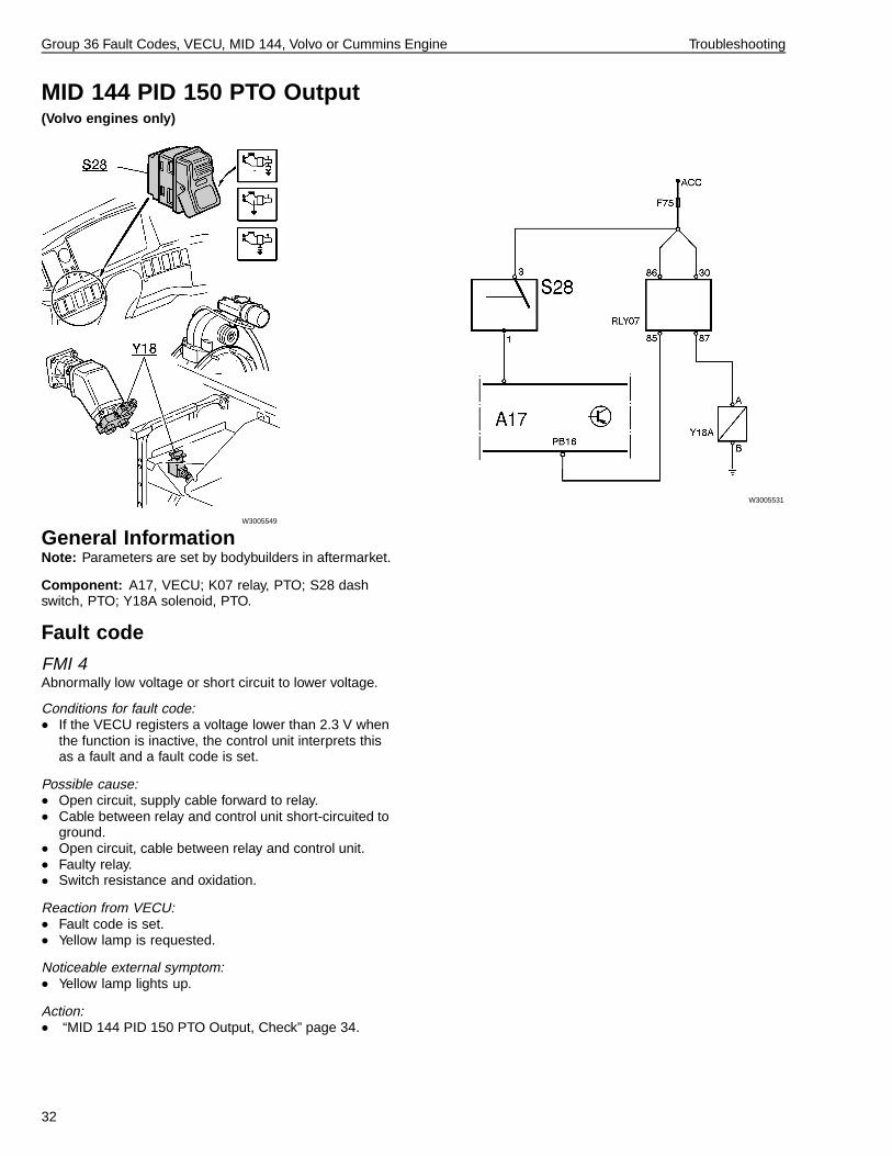
MID 144 PID 150 PTO Output(Volvo engines only)
W3005549
W3005531
General InformationNote: Parameters are set by bodybuilders in aftermarket.
Component: A17, VECU; K07 relay, PTO; S28 dashswitch, PTO; Y18A solenoid, PTO.
Fault code
FMI 4Abnormally low voltage or short circuit to lower voltage.
Conditions for fault code:• If the VECU registers a voltage lower than 2.3 V when
the function is inactive, the control unit interprets thisas a fault and a fault code is set.
Possible cause:• Open circuit, supply cable forward to relay.• Cable between relay and control unit short-circuited to
ground.• Open circuit, cable between relay and control unit.• Faulty relay.• Switch resistance and oxidation.
Reaction from VECU:• Fault code is set.• Yellow lamp is requested.
Noticeable external symptom:• Yellow lamp lights up.
Action:• “MID 144 PID 150 PTO Output, Check” page 34.
32

Group 36 Fault Codes, VECU, MID 144, Volvo or Cummins Engine Troubleshooting
General InformationNote: Parameters are set by bodybuilders in aftermarket.
Component: A17, VECU; K07 relay, PTO; S28 dashswitch, PTO; Y18A solenoid, PTO.
Fault code
FMI 4Abnormally low voltage or short circuit to lower voltage.
Conditions for fault code:• If the VECU registers a voltage lower than 2.3 V when
the function is inactive, the control unit interprets thisas a fault and a fault code is set.
Possible cause:• Open circuit, supply cable forward to relay.• Cable between relay and control unit short-circuited to
ground.• Open circuit, cable between relay and control unit.• Faulty relay.• Switch resistance and oxidation.
Reaction from VECU:• Fault code is set.• Yellow lamp is requested.
Noticeable external symptom:• Yellow lamp lights up.
Action:• “MID 144 PID 150 PTO Output, Check” page 34.
33

Group 36 Fault Codes, VECU, MID 144, Volvo or Cummins Engine Troubleshooting
3649-21-03-01MID 144 PID 150 PTO Output, Check
(Volvo engines only)Special tools: 9998533, 9998699Other special equipment: J39200
NOTE!• Read off the other fault codes for the VECU.
• Switch off the current in the vehicle before theconnectors are disconnected.
• Check for loose connections, switch resistance, andoxidation. For information concerning fault tracing ofwires and connectors, refer to Service Information,group 37.
Measurement at componentconnector to VECUNote: Faults in the wiring harness to the VECUcan damage the component. Therefore, a check ofthe component should also be made if any of themeasurement values deviate.
Ground wire
1
Prerequisites:• Connector to relay K07 removed.• Adapter connected to the VECU.• Measure resistance using multimeter.• VECU connected.• Ignition key in OFF position.• Measurement to the VECU.
Measuring points Expected value
PB16 - ground 3.4 M
998533, 9998699J39200
Wiring harness
2Check the wiring harness; refer to Service Information,group 37.
34

Group 36 Fault Codes, VECU, MID 144, Volvo or Cummins Engine Troubleshooting
Check of componentNote: Faults in the component can be caused by faultsin the wiring harness of the control unit. Therefore, acheck of the wiring harness should also be made beforeconnecting a new component.
Relay
1
Prerequisites:• Measurement box with adapter connected between
VECU connector PB and wiring harness.• Ignition key in DRIVE position.• Switch PTO active.• Check of the solenoid valve.
Earth Checks
PB16 - ground Listen for sound from the relay
9998533, 9998699J39200
Check of subsystem
Ground wire
1
Prerequisites:• Measurement box with adapter connected between
VECU connector PB and wiring harness.• Measure voltage using multimeter.• VECU connected.• Ignition key in DRIVE position.• Switch PTO active.
Measuring points Expected value
PB16 - PB19 B+ (relay inactive)0 V (relay active)
9998533, 9998699J39200
35

Group 36 Fault Codes, VECU, MID 144, Volvo or Cummins Engine Troubleshooting
MID 144 PID 152 VECU, Number of Resets
W3005048
General InformationThe software in the VECU contains an internal checkingfunction that restarts the control unit when there is afault in the execution of the software. PID 152 containsinformation about how many such restarts that have beenmade.
Component: A17, VECU.
Fault code
FMI 12Faulty unit or component.
Conditions for fault code:• If an internal software fault occurs an info code is set.
Possible cause:• The system has been restarted due to an internal
software fault.
Reaction from VECU:• Fault code is set.• The system is restarted.
36
Group 36 Fault Codes, VECU, MID 144, Volvo or Cummins Engine Troubleshooting
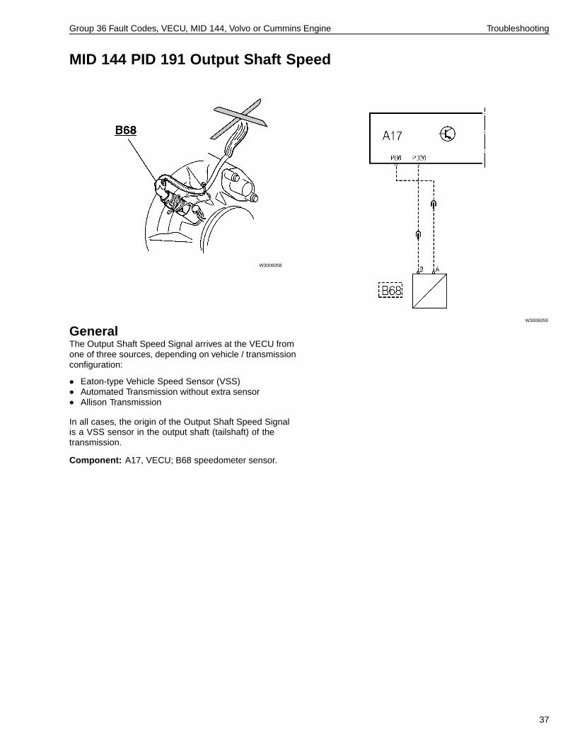
MID 144 PID 191 Output Shaft Speed
W3006058
W3006059
GeneralThe Output Shaft Speed Signal arrives at the VECU fromone of three sources, depending on vehicle / transmissionconfiguration:
• Eaton-type Vehicle Speed Sensor (VSS)• Automated Transmission without extra sensor• Allison Transmission
In all cases, the origin of the Output Shaft Speed Signalis a VSS sensor in the output shaft (tailshaft) of thetransmission.
Component: A17, VECU; B68 speedometer sensor.
37

Group 36 Fault Codes, VECU, MID 144, Volvo or Cummins Engine Troubleshooting
Fault code
FMI 2Intermittent or incorrect data.
Conditions for fault code:• The VECU can receive vehicle speed information
over the J1939 Control Data Link from certaintransmissions. This FMI will occur if the VECU isexpecting such data but does not receive it.
Note: First read and correct fault codes from thetransmission ECU, if applicable.
Possible cause:• Fault in wiring harness, control link.• Fault in vehicle speed sensor or VSS wiring to
transmission ECU.
Reaction from VECU:• Fault code is set.• Yellow lamp is requested.
Noticeable external symptom:• Yellow lamp lights up.• No vehicle speed in gauge.• No PTO or cruise control.
Action:• Troubleshoot J1939 Control Data Link; refer to Service
Information, group 37.• “MID 144 PID 191 Output Shaft Speed, Check” page
40.
FMI 5Abnormally low current or open circuit.
Conditions for fault code:• If the VECU registers a current lower than 90 µA on
any of the signal wires from the speed sensor theVECU interprets this as a fault and a fault code is set.
Possible cause:
• Poor contact, sensor connection.
• Switch resistance and oxidation.
• Break, signal wire.
• Fault in sensor.
Reaction from the VECU:
• Yellow lamp lights up.
Noticeable external symptom:
• No vehicle speed on gauge.
• No PTO.
• No cruise control.
Action:
• “MID 144 PID 191 Output Shaft Speed, Check” page40.
38

Group 36 Fault Codes, VECU, MID 144, Volvo or Cummins Engine Troubleshooting
FMI 6Abnormally high current or short circuit.
Conditions for fault code:• If the VECU registers a current higher than 140 µA
on any of the signal wires from the speed sensor, theVECU interprets this as a fault and a fault code is set.
Possible cause:
• Signal wire short-circuited to higher voltage.
• Signal wire short-circuited to ground.
• Signal wires short-circuited to each other.
• Fault in sensor.
Reaction from the VECU:
• Yellow lamp lights up.
Noticeable external symptom:
• No vehicle speed on gauge.
• No PTO.
• No cruise control.
Action:
• Troubleshoot J1939 Control Data Link; refer to ServiceInformation, group 37.
• “MID 144 PID 191 Output Shaft Speed, Check” page40.
39

Group 36 Fault Codes, VECU, MID 144, Volvo or Cummins Engine Troubleshooting
3649-21-03-28MID 144 PID 191 Output Shaft Speed, Check
Special tools: 9990151, 9998533, 9998699Other special equipment: J39200
NOTE!• Read off the other fault codes for the VECU,
speedometer, and brake control unit.• Switch off the current in the vehicle before the
connectors are disconnected.• Check for loose connections, switch resistance, and
oxidation. For information concerning fault tracing ofwires and connectors, refer to Service Information,group 37.
Tests Using PC ToolThe following tests are useful for closely examining thecomponent’s function:
• “Cruise control switch, test”
The test allows you to read the speed signal from theVECU.
Determination of Output ShaftSpeed Sensor ConfigurationThe appropriate check of the system will depend on theconfiguration of the Vehicle Speed sensor and circuits.Use the following information to determine which systemthe vehicle has:
• Eaton-Type Vehicle Speed Sensor
Use this check whenever FMI 5 or 6 is present.This type of Vehicle Speed Sensor (VSS) will befound on the tailshaft of manual transmissions.It may also be found on some automatedtransmissions (Eaton Autoshift, Eaton Lightning)when two VSS are present in the tailshaft - oneVSS will be wired directly to the TransmissionECU, the other will be wired to the VECU(circuits 550/551).
• Automated Transmission without Extra Sensor
If only one VSS is found on an automatedtransmission (Eaton Autoshift, Eaton Lightning)the VECU is receiving Outputshaft Speedinformation from the Transmission ECU overthe J1939 datalink.All Meritor / ZF FreedomLine transmissions fallinto this category.
• Allison Transmission
Use this section if the vehicle is equipped with anAllison MD or HD transmission.
40

Group 36 Fault Codes, VECU, MID 144, Volvo or Cummins Engine Troubleshooting
Measurement at componentconnector to VECUNote: Faults in the wiring harness to the VECUcan damage the component. Therefore, a check ofthe component should also be made if any of themeasurement values deviate.
• Eaton-type Vehicle Speed Sensor (VSS)
For this type of VSS, 3 checks can be performed:
1 Prerequisites:
• Ignition key in OFF position.• Measurement box inserted at VECU
(disconnected at VECU side).• Vehicle Speed Sensor at transmission connected.• Measure resistance, harness side of PB6 – PB20,
“looking toward” VSS.•
Measuring points Expected value
PB6 - PB20 2.0 - 4.0 k
2 Prerequisites:
• Ignition key in OFF position.• Measurement box inserted at VECU
(disconnected at VECU side).• Vehicle Speed Sensor at transmission
disconnected.• Make sure PB6 and PB20 are not shorted to
ground, power, or each other.•
Measuring points Expected value
PB6 - PB20 OL
PB6 - ground OL
PB20 - ground OL
3 Prerequisites:
• Ignition key in ON position.• Measurement box inserted at VECU (connected
at VECU).• Vehicle Speed Sensor at transmission connected.• Vehicle must be stationary.• Measure voltage across PB6 – PB20.
Measuring points Expected value
PB6 - PB20 1.25 - 1.75 Vdc (average)varying between approx. 1.0 and 2.0 V
41

Group 36 Fault Codes, VECU, MID 144, Volvo or Cummins Engine Troubleshooting
• Automated Transmission without Extra Sensor
1 If two Vehicle Speed Sensors (VSS) are presentin the transmission’s tailshaft and the PID 191fault code set by the VECU is FMI 5 or 6, usethe troubleshooting for the Eaton-type VehicleSpeed Sensor (above).
2 If only one VSS is present in the tailshaft (or ifnone are visible, as is the case with the Meritor /ZF FreedomLine), then the VECU is receiving itsinformation over the J1939 Control Data Link.Another way to tell that the VECU is receiving theinformation over the Data Link is by the FMI thatthe VECU is using - if the fault code is PID 191FMI 2, this indicates that the VECU is expectingthe data over the J1939 Control Data Link butis not receiving it.
3 In these cases, troubleshoot any fault codes in thetransmission ECU first. If the trouble remains,refer to troubleshooting information for the SAEJ1939 Control Data Link, group 37.
• Allison Transmission
1 The Output Shaft Speed information from AllisonTransmissions will be obtained one of two ways:
• A hardwire connection from the Allison ECU(Black connector, pin 30, circuit A215) tothe VECU (PB6, circuit 550). This signalis a square-wave reproduction of the VSSlocated in the Allison’s tailshaft.
• Over the J1939 Control Data Link. (NOTE:even if obtaining the information over theData Link, the hardwire connection maystill be in place.)
In either case, troubleshoot any fault codes in theAllison transmission ECU first.
2 If the PID 191 fault code in the VECU is FMI 2,this indicates that the VECU is configured toreceive the VSS information over the J1939Control Data Link. If the problem remains, refer totroubleshooting information for the SAE J1939Control Data Link, group 37.
3 If FMI 2 is not indicated, or there are no fault codespresent in the VECU but a speed-related problemstill exists, troubleshoot the hardwire connectionbetween the Allison Transmission ECU and theVECU. Refer to Service Information, group 37.
42

Group 36 Fault Codes, VECU, MID 144, Volvo or Cummins Engine Troubleshooting
Check of ComponentNote: Faults in the component can be caused by faultsin the wiring harness of the control unit. Therefore, acheck of the wiring harness should also be made beforeconnecting a new component.
• Eaton-Type Vehicle Speed Sensor (VSS)
For the Eaton-type VSS, one check can be performedat the VSS:
Prerequisites:• Vehicle Speed Sensor at transmission disconnected.• Measure resistance of sensor using tool 9990151.
Measuring points Expected value
A - B 2.0 - 4.0 k
• Automated Transmission without Extra Sensor
No relevant measurements; refer to the appropriateservice literature for the transmission manufacturer.
• Allison Transmission
No relevant measurements; refer to the appropriateservice literature for the transmission manufacturer.
VerificationUsing the PC tool, check that the fault has been corrected(see “Tests Using PC Tool” page 23).
43

Group 36 Fault Codes, VECU, MID 144, Volvo or Cummins Engine Troubleshooting
MID 144 PPID 61 Engine Brake Switch(Volvo engines only)
W3005545
W3005532
General InformationComponent: A17, VECU; S07, engine brake switch,selector type.
EPG 2-position Volvo Engine Brake(OFF/ON)
VEB 3-position Volvo Engine Brake(OFF/50%/100%)
Fault code
FMI 7Incorrect response from mecanical system.
Conditions for fault code:• If the VECU receives signals for PA20 active and PA21
inactive at the same time, the control unit will interpretit as a fault and a fault code will be set.
Possible cause:• Faulty switch.• Fault in wiring harness.
Reaction from VECU:• Fault code is set.• Yellow lamp is requested.
Noticeable external symptom:• Engine brake cannot be activated.• Yellow lamp lights up.
Action:• “MID 144 PPID 61 Engine Brake Switch, Check” page
45.
44

Group 36 Fault Codes, VECU, MID 144, Volvo or Cummins Engine Troubleshooting
3649-21-03-04MID 144 PPID 61 Engine Brake Switch, Check
Special tools: 9990008, 9998699Other special equipment: 9813194, J39200
NOTE!• Read off the other fault codes for the VECU.• Switch off the current in the vehicle before the
connectors are disconnected.• Check for loose connections, switch resistance, and
oxidation. For information concerning fault tracing ofwires and connectors, refer to Service Information,group 37.
Tests Using PC ToolThe following tests are useful for checking componentfunction:
• Exhaust brake function, test
• MID 144, pinout test
Measurement at componentconnector to VECUNote: Faults in the wiring harness to the VECUcan damage the component. Therefore, a check ofthe component should also be made if any of themeasurement values deviate.
Signal wire, engine brake switch
1Note: The check below applies only to vehicles equippedwith Volvo Engine Brake.
Prerequisites:• Connector to engine brake switch disconnected.• Measure resistance using multimeter.• VECU connected.• Ignition key in OFF position.• Measurement to the VECU.
Measuring points Expected value
5 - ground 2.1 - 3.1 k (VCB)
6 - ground 2.1 - 3.1 k (EPG)
9990008J39200
Wiring harness
2Check the wiring harness; refer to Service Information,group 37.
45

Group 36 Fault Codes, VECU, MID 144, Volvo or Cummins Engine Troubleshooting
Check of componentNote: Faults in the component can be caused by faultsin the wiring harness of the control unit. Therefore, acheck of the component should also be made beforeconnecting a new component.
Check of engine brake switch
1Note: The check below applies only to vehicles equippedwith Volvo Engine Brake (EBR-VEB).
Prerequisites:• Connector to switch, for engine brake disconnected.• Measure resistance using multimeter.• Ignition key in OFF position.• Measurement at switch for engine brake.
Measuring points Expected value
1 - 6 ∞ (EPG inactive)0 (EPG active)0 (VCB active, if the vehicle is equipped with VCB)
1 - 5 ∞ (VCB and EPG inactive, if the vehicle is equippedwith VCB)0 (VCB active, if the vehicle is equipped with VCB)
9990008J39200
46

Group 36 Fault Codes, VECU, MID 144, Volvo or Cummins Engine Troubleshooting
Check of subsystem
Signal wire, engine brake switch
1Note: The check below applies only to vehicles equippedwith Volvo Engine Brake (EBR-VEB).
Prerequisites:• Measurement box with adapter connected between
VECU connector PA and wiring harness.• Measure voltage using multimeter.• VECU connected.• Ignition key in DRIVE position.
Measuring points Expected value
PA21 - PA12 0 V (EPG inactive)B+ (EPG active)B+ (VCB active, if the vehicle is equipped with VCB)
PA20 - PA12 0 V (VCB and EPG inactive, if the vehicle is equipped withVCB)B+ (VCB active, if the vehicle is equipped with VCB)
9998699, 9813194J39200
VerificationUsing the PC tool, check that the fault has been corrected(see “Tests Using PC Tool” page 45).
47

Group 36 Fault Codes, VECU, MID 144, Volvo or Cummins Engine Troubleshooting
MID 144 PPID 69 Buffered Idle Validation Switch(Volvo engines only)
W3005546
W3005533
General InformationThe function is used to be able to drive the vehicle atincreased idling speed if a fault has occurred in the datalinks to the engine ECU.
Component: A14, EECU; A17, VECU.
Fault code
FMI 4Abnormally low voltage or short circuit to lower voltage.
Conditions for fault code:• If the output signal from the buffered idle validation
switch deviates from the input signal from idle switch1, the control unit interprets this as a fault and a faultcode is set.
Note: The fault code is set first when the acceleratorpedal is depressed.
Possible cause:• Signal cable short-circuited to ground.
Reaction from VECU:• Fault code is set.• Yellow lamp is requested.
Noticeable external symptom:• Yellow lamp lights up.
Action:• “MID 144 PPID 69 Buffered Idle Validation Switch,
Check” page 49.
48

Group 36 Fault Codes, VECU, MID 144, Volvo or Cummins Engine Troubleshooting
3649-21-03-10MID 144 PPID 69 Buffered Idle Validation Switch, Check
(Volvo engines only)Special tools: 9990014, 9990062, 9998533,9998699Other special equipment: J39200
NOTE!• Read off the other fault codes for the VECU.• Switch off the current in the vehicle before the
connectors are disconnected.• Check for loose connections, switch resistance, and
oxidation. For information concerning fault tracing ofwires and connectors, refer to Service Information,group 37.
Measurement at componentconnector to VECUNote: Faults in the wiring harness to the VECUcan damage the component. Therefore, a check ofthe component should also be made if any of themeasurement values deviate.
Signal cable
1
Prerequisites:• EECU’s connector disconnected.• Measurement box connected to the VECU.• Measure voltage using multimeter.• VECU connected.• Ignition key in DRIVE position.• Measurement at the VECU.
Measuring points Expected value
EB15 - ground 0 V (no acceleration)B+ (full acceleration)
9990014, 9990062J39200
Wiring harness
2Check the wiring harness; refer to Service Information,group 37.
49

Group 36 Fault Codes, VECU, MID 144, Volvo or Cummins Engine Troubleshooting
Check of componentNote: Faults in the component can be caused by faultsin the wiring harness of the control unit. Therefore, acheck of the wiring harness should also be made beforeconnecting a new component.
Buffered idle validation switch
1
Prerequisites:• EECU connector disconnected.• Measurement box connected to the EECU.• Measure resistance using multimeter.• Ignition key in OFF position.• Measurement at the EECU.
Measuring points Expected value
EB15 - EB59 2.3 - 3.5 k
9990014, 9990062J39200
Check of subsystemNote: If measurement box 9990014 (with adapter9990062) is already connected to connector EB at theEECU, the check can more simply be carried out fromhere. Connect the measurement box between EECUconnector EB and wiring harness. Connect a multimeterto the measurement box and measure the voltage (EB4 -EB9). See the expected values below.
Signal cable
1
Prerequisites:• Measurement box with adapter connected between
VECU connector PB and wiring harness.• Measure voltage using multimeter.• VECU connected.• Ignition key in DRIVE position.
Measuring points Expected value
0 V (no acceleration)PB17 - PB22
B+ (full acceleration)
9998533, 9998699J39200
50

Group 36 Fault Codes, VECU, MID 144, Volvo or Cummins Engine Troubleshooting
MID 144 PPID 70 Pedal Switches, Supply
W3006774
W3006777
General InformationVoltage supply to pedal switches.
Note: If vehicle is not equipped with a clutch pedal, clutchswitch (S58) may be replaced with a jumper wire fromthe factory. Leave jumper wire in place and performtroubleshooting on circuit as if clutch switch were installed(with switch closed).
Component: A17, VECU; S58, position switch, clutchpedal; S59, position switch, brake pedal; B25, sensor,accelerator pedal.
Fault code
FMI 4Abnormally low voltage or short circuit to ground.
Conditions for fault code:• If the VECU registers a voltage lower than 3.0 V on the
supply cable, the control unit interprets this as a faultand a fault code is set.
Possible cause:• Supply wire short-circuited to ground.• Signal wire for idle switch 1 short-circuited to ground.• Signal wire for brake switch short-circuited to ground.• Signal wire for clutch switch (if the vehicle is equipped
with clutch pedal) short-circuited to ground.• Faulty switch.
Reaction from VECU:• Fault code is set.• Yellow lamp is requested.
Noticeable external symptom:• Yellow lamp lights up.
Action:• “MID 144 PPID 70 Pedal Switches, Supply, Check”
page 52.
51

Group 36 Fault Codes, VECU, MID 144, Volvo or Cummins Engine Troubleshooting
3649-21-03-11MID 144 PPID 70 Pedal Switches, Supply, Check
Special tools: 88890016, 9998533, 9990008,9998699Other special equipment: 9813194, J39200
NOTE!• Read off the other fault codes for the VECU.
• Switch off the current in the vehicle before theconnectors are disconnected.
• Check for loose connections, switch resistance, andoxidation. For information concerning fault tracing ofwires and connectors, refer to Service Information,group 37.
Tests Using PC ToolThe following tests are useful for closely examining thecomponent’s function:
• Accelerator pedal switches and sensors, test• Cruise control switch, test• MID 144, pinout test
Measurement at componentconnector to VECUNote: Faults in the wiring harness to the VECUcan damage the component. Therefore, a check ofthe component should also be made if any of themeasurement values deviate.
Supply wire, idle validation switch 1
1
Prerequisites:• Connector to the accelerator pedal sensor
disconnected.• Adapter connected to accelerator pedal.• The following other pedal connectors disconnected:
• Brake pedal switch (two sockets).• Clutch pedal switch (if equipped with clutch pedal).
• Measure voltage using multimeter.• VECU connected.• Ignition key in DRIVE position.• Measurement to the VECU.
Measuring points Expected value
3 - ground B+
88890016J39200
52

Group 36 Fault Codes, VECU, MID 144, Volvo or Cummins Engine Troubleshooting
Signal wire, idle validation switch 1
2
Prerequisites:• Connector to the accelerator pedal sensor
disconnected.• Measurement box with adapter connected to the
VECU.• Measure resistance using multimeter.• VECU connected.• Ignition key in OFF position.• Measurement to the VECU.
Measuring points Expected value
1 (common) - ground 2.1 - 3.1 k
88890016J39200
Supply wire, brake pedal switch
3
Prerequisites:• Connector to the brake pedal switch (two sockets)
disconnected.• The following other pedal connectors disconnected:
• Accelerator pedal sensor.• Clutch pedal switch (if equipped with clutch pedal).
• Measure voltage using multimeter.• VECU connected.• Ignition key in DRIVE position.• Measurement to the VECU.
Measuring points Expected value
C (common) - ground B+
9990008J39200
53

Group 36 Fault Codes, VECU, MID 144, Volvo or Cummins Engine Troubleshooting
Signal wire, brake pedal switch
4
Prerequisites:• Connector to the brake pedal switch (two sockets)
disconnected.• Measure resistance using multimeter.• VECU connected.• Ignition key in OFF position.• Measurement to the VECU.
Measuring points Expected value
NO (normally open) - ground 2.1 - 3.1 k
9990008J39200
Supply wire, clutch pedal switch
5
Prerequisites:• Connector to the clutch pedal switch (two sockets)
disconnected (if the vehicle is equipped with clutchpedal).
• The following other pedal connectors disconnected:
• Accelerator pedal sensor.• Brake pedal switch (two sockets).
• Measure voltage using multimeter.• VECU connected.• Ignition key in DRIVE position.• Measurement to the VECU.
Measuring points Expected value
C (common) - ground B+
9990008J39200
54

Group 36 Fault Codes, VECU, MID 144, Volvo or Cummins Engine Troubleshooting
Signal wire, clutch pedal switch
6
Prerequisites:• Connector to the clutch pedal switch (two sockets)
disconnected (if equipped with clutch pedal).• Measure resistance using multimeter.• VECU connected.• Ignition key in OFF position.• Measurement to the VECU.
Measuring points Expected value
NO (normally open) - ground 2.1 - 3.1 k
9990008J39200
Wiring harness
7Check the wiring harness; refer to Service Information,group 37.
Check of componentNote: Faults in the component can be caused by faultsin the wiring harness of the control unit. Therefore, acheck of the wiring harness should also be made beforeconnecting a new component.
Idle validation switch 1
1
Prerequisites:• Connector to the accelerator pedal sensor
disconnected.• Measurement box with adapter connected to the
accelerator pedal sensor.• Measure resistance using multimeter.• Ignition key in OFF position.• Measurement at the accelerator pedal sensor.
Measuring points Expected value
1 - 3 ∞ (no acceleration)20 - 90 (full acceleration)
88890016J39200
55

Group 36 Fault Codes, VECU, MID 144, Volvo or Cummins Engine Troubleshooting
Brake pedal switch
2
Prerequisites:• Connector to the brake pedal switch (two sockets)
disconnected.• Measure resistance using multimeter.• Ignition key in OFF position.• Measurement at brake pedal switch.
Measuring points Expected value
“C” - “NO” 0 (brake pedal at rest)∞ (brake pedal depressed)
9990008J39200
Clutch pedal switch
3
Prerequisites:• Connector to the clutch pedal switch (two sockets)
disconnected (if the vehicle is equipped with clutchpedal).
• Measure resistance using multimeter.• Ignition key in OFF position.• Measurement at the clutch pedal switch.
Measuring points Expected value
“C” - “NO” 0 (clutch pedal at rest)∞ (clutch pedal depressed)
9990008J39200
56

Group 36 Fault Codes, VECU, MID 144, Volvo or Cummins Engine Troubleshooting
Check of subsystem
Supply wire, pedal switches
1
Prerequisites:• Measurement box with adapter connected between
VECU connector PA and wiring harness.• Measurement box with adapter connected between
VECU connector PB and wiring harness.• Measure voltage using multimeter.• VECU connected.• Ignition key in DRIVE position.
Measuring points Expected value
PB19 - PA12 B+
9998533, 9998699, 9813194J39200
Signal wire, idle validation switch 1
2
Prerequisites:• Measurement box with adapter connected between
VECU connector PA and wiring harness.• Measure voltage using multimeter.• VECU connected.• Ignition key in DRIVE position.
Measuring points Expected value
0 V (no acceleration)PA23 - PA12
B+ (full acceleration)
9998533, 9998699J39200
57
Group 36 Fault Codes, VECU, MID 144, Volvo or Cummins Engine Troubleshooting
Signal wire, brake pedal switch
3
Prerequisites:• Measurement box with adapter connected between
VECU connector PA and wiring harness.• Measure voltage using multimeter.• VECU connected.• Ignition key in DRIVE position.
Measuring points Expected value
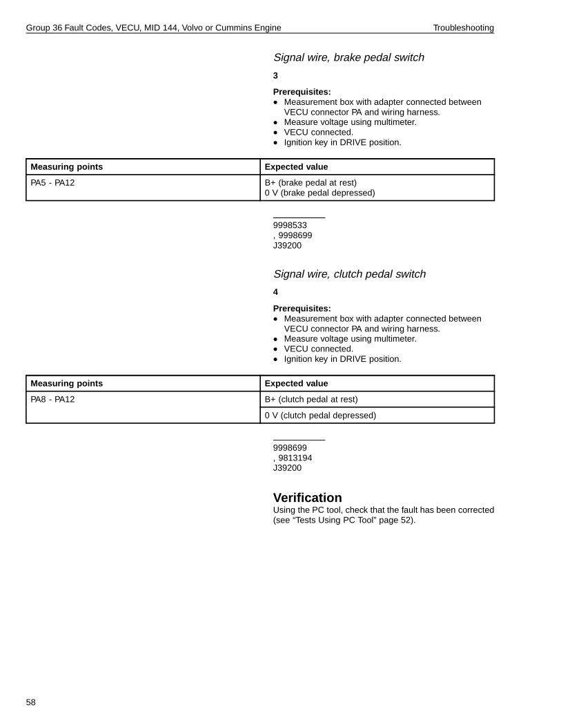
PA5 - PA12 B+ (brake pedal at rest)0 V (brake pedal depressed)
9998533, 9998699J39200
Signal wire, clutch pedal switch
4
Prerequisites:• Measurement box with adapter connected between
VECU connector PA and wiring harness.• Measure voltage using multimeter.• VECU connected.• Ignition key in DRIVE position.
Measuring points Expected value
B+ (clutch pedal at rest)PA8 - PA12
0 V (clutch pedal depressed)
9998699, 9813194J39200
VerificationUsing the PC tool, check that the fault has been corrected(see “Tests Using PC Tool” page 52).
58

Group 36 Fault Codes, VECU, MID 144, Volvo or Cummins Engine Troubleshooting
MID 144 PPID 71 Cruise Control and Engine Brake, Switch Supply
W3005548
W3005650
General InformationVoltage supply to switch for cruise control and enginebrake control.
Component: S07 engine brake switch, selector type;S24 engine brake stalk switch (Cummins EBR-CBJ6only); S25 switch unit, cruise control.
59

Group 36 Fault Codes, VECU, MID 144, Volvo or Cummins Engine Troubleshooting
Fault code
FMI 4Abnormally low voltage or short circuit to lower voltage.
Conditions for fault code:• If the VECU registers a voltage lower than 3.0 V on the
supply cable, the control unit interprets this as a faultand a fault code is set.
Possible cause:• Supply wire short-circuited to ground.• Signal wire for cruise control, SET+/SET-
/RESUME/ON, short-circuited to ground.• Signal wire for engine brake switch (if the vehicle is
equipped with engine brake), EPG/VCB, short-circuitedto ground.
• Signal wire for engine brake stalk switch (if equippedwith engine brake), short-circuited to ground.
• Faulty contact or switch.• Switch resistance and oxidation.
Reaction from VECU:• Fault code is set.• Yellow lamp is requested.
Noticeable external symptom:• Yellow lamp lights up.• All functions in the cruise control cannot be used.• All functions for engine brake cannot be used.• Engine does not respond to full acceleration.
Action:• “MID 144 PPID 71 Cruise Control and Engine Brake,
Switch Supply, Check” page 61.
60

Group 36 Fault Codes, VECU, MID 144, Volvo or Cummins Engine Troubleshooting
3649-21-03-12MID 144 PPID 71 Cruise Control and Engine Brake, Switch Supply,
CheckSpecial tools: 9990008, 9998533, 9998699Other special equipment: 9813194, J39200
NOTE!• Read off the other fault codes for the VECU.• Switch off the current in the vehicle before the
connectors are disconnected.• Check for loose connections, switch resistance, and
oxidation. For information concerning fault tracing ofwires and connectors, refer to Service Information,group 37.
Tests Using PC ToolThe following tests are useful for closely examining thecomponent’s function:
• Cruise control switch, test• Engine brake function, test
Measurement at the component’sconnector to VECUNote: Faults in the wiring harness to the VECUcan damage the component. Therefore, a check ofthe component should also be made if any of themeasurement values deviate.
Supply wire, cruise control switch
1
Prerequisites:• Connector to Cruise control switch disconnected.• Measurement box with adapter connected to the
VECU.• Connector to engine brake switch disconnected (if the
vehicle is equipped with engine brake).• Measure voltage using multimeter.• VECU connected.• Ignition key in DRIVE position.• Measurement to the VECU.
61

Group 36 Fault Codes, VECU, MID 144, Volvo or Cummins Engine Troubleshooting
Measuring points Expected value
1 - ground B+
9990008, J39200
Signal wire, Cruise control switch
2
Prerequisites:• Connector to Cruise control switch disconnected.• Measurement box with adapter connected to the
VECU.• VECU connected.• Ignition key in OFF position.• Measurement to the VECU.
Measuring points Expected value
5 - ground 2.1 - 3.1 k (SET+)
3 - ground 2.1 - 3.1 k (RESUME)
2 - ground 2.1 - 3.1 k (ON)
4 - ground 2.1 - 3.1 k (SET-)
9990008, J39200
Supply wire, engine brake switch (Volvoengine)
3Note: The check below applies only to vehicles equippedwith Volvo Engine Brake (EBR-VEB).
Prerequisites:• Connector to dash engine brake switch disconnected.• Connector to Cruise control switch disconnected.• Measure voltage using multimeter.• VECU connected.• Ignition key in DRIVE position.• Measurement to the VECU.
Measuring points Expected value
1 - ground B+
9990008, J39200
62

Group 36 Fault Codes, VECU, MID 144, Volvo or Cummins Engine Troubleshooting
Signal wire, engine brake switch
4Note: The check below applies only to vehicles equippedwith Volvo Engine Brake (EBR-VEB).
Prerequisites:• Connector to dash engine brake switch disconnected.• Measure resistance using multimeter.• VECU connected.• Ignition key in OFF position.• Measurement to the VECU.
Measuring points Expected value
5 - ground 2.1 - 3.1 k (VCB)
6 - ground 2.1 - 3.1 k (EPG)
9990008, J39200
Supply wire, engine brake switch stalk lever(Cummins engine)
5Note: The check below applies only to vehicles equippedwith engine brake stalk switch (Cummins EBR-CBJ6).
Prerequisites:• Connector to stalk lever, engine brake disconnected.• Measurement box with adapter connected to the
VECU.• Connector to Cruise control switch disconnected.• Measure voltage using multimeter.• VECU connected.• Ignition key in DRIVE position.• Measurement to the VECU.
Measuring points Expected value
1 - ground B+
9990008, J39200
63

Group 36 Fault Codes, VECU, MID 144, Volvo or Cummins Engine Troubleshooting
Signal wire, engine brake switch lever(Cummins engine)
6Note: The check below applies only to vehicles equippedwith engine brake stalk lever (Cummins EBR-CBJ6).
Prerequisites:• Connector to stalk lever, engine brake disconnected.• Measurement box with adapter connected to the
VECU.• Measure resistance using multimeter.• VECU connected.• Ignition key in OFF position.• Measurement to the VECU.
Measuring points Expected value
3 - ground ∞ (OFF)2.1 - 3.1 k (ON)
9990008, J39200
Wiring harness
7Check the wiring harness; refer to Service Information,group 37.
Check of componentNote: Faults in the component can be caused by faultsin the wiring harness of the control unit. Therefore, acheck of the wiring harness should also be made beforeconnecting a new component.
64

Group 36 Fault Codes, VECU, MID 144, Volvo or Cummins Engine Troubleshooting
Switch for the cruise control
1
Prerequisites:• Connector to Cruise control switch disconnected.• Measurement box with adapter connected to switch
cruise control.• Measure resistance using multimeter.• Ignition key in OFF position.• Measurement at switch cruise control.
Measuring points Expected value
∞ (SET+ inactive)1 - 5
0 (SET+ active)
∞ (RESUME inactive)1 - 3
0 (RESUME active)
∞ (OFF)
0 (ON)
1 - 2
0 (RESUME active)
∞ (SET- inactive)
0 (SET- active)
1 - 4
∞ (SET+ active)
9990008, J39200
Check of the dash switch for engine brake(Volvo engines)
2Note: The check below applies only to vehicles equippedwith Volvo Engine Brake (EBR-VEB).
Prerequisites:• Connector to dash engine brake switch disconnected.• Measure resistance using multimeter.• Ignition key in OFF position.• Measurement at dash switch for engine brake.
Measuring points Expected value
1 - 6 ∞ (EPG inactive)0 (EPG active)0 (VCB active, if the vehicle is equipped with VCB)
1 - 5 ∞ (VCB and EPG inactive, if the vehicle is equippedwith VCB)0 (VCB active, if the vehicle is equipped with VCB)
9990008, J39200
65

Group 36 Fault Codes, VECU, MID 144, Volvo or Cummins Engine Troubleshooting
Check of stalk lever for the engine brake(Cummins engine)
3Note: The check below applies only to vehicles equippedwith engine brake stalk lever (Cummins EBR-CBJ6).
Prerequisites:• Connector to stalk lever, engine brake disconnected.• Measurement box with adapter connected to stalk
lever, engine brake.• Measure resistance using multimeter.• Ignition key in OFF position.• Measurement at stalk lever, engine brake.
Measuring points Expected value
1 - 3 ∞ (OFF)0 (ON)
9990008, J39200
Check of subsystem
Supply wire
1
Prerequisites:• Measurement box with adapter connected between
VECU connector PA and wiring harness.• Measurement box with adapter connected between
VECU connector PB and wiring harness.• Measure voltage using multimeter.• VECU connected.• Ignition key in DRIVE position.
Measuring points Expected value
PB5 - PA12 B+
9998533, 9998699, 9813194, J39200
66

Group 36 Fault Codes, VECU, MID 144, Volvo or Cummins Engine Troubleshooting
Signal wire, Cruise control switch
2
Prerequisites:• Measurement box with adapter connected between
VECU connector PA and wiring harness.• Measure voltage using multimeter.• VECU connected.• Ignition key in DRIVE position.
Measuring points Expected value
PA2 - PA12 0 V (SET+ inactive)B+ (SET+ active)
PA30 - PA12 0 V (RESUME inactive)B+ (RESUME active)
PA3 - PA12 0 V (OFF)B+ (ON)B+ (RESUME active)
PA1 - PA12 0 V (SET - inactive)B+ (SET- active)0 V (SET+ active)
9998533, 9998699, 9813194, J39200
Signal wire, engine brake switch (Volvoengine)
3Note: The check below applies only to vehicles equippedwith Volvo Engine Brake (EBR-VEB).
Prerequisites:• Measurement box with adapter connected between
VECU connector PA and wiring harness.• Measure voltage using multimeter.• VECU connected.• Ignition key in DRIVE position.
Measuring points Expected value
PA21 - PA12 0 V (EPG inactive)B+ (EPG requested)B+ (VCB requested, if equipped)
PA20 - PA12 0 V (VCB and EPG inactive, if equipped)B+ (VCB requested, if equipped)
9998699, 9813194, J39200
67

Group 36 Fault Codes, VECU, MID 144, Volvo or Cummins Engine Troubleshooting
Signal wire, engine brake switch stalk lever(Cummins engine)
4Note: The check below applies only to vehicles equippedwith engine brake stalk lever (Cummins EBR-CBJ6).
Prerequisites:• Measurement box with adapter connected between
VECU connector PA and wiring harness.• Measure voltage using multimeter.• VECU connected.• Ignition key in DRIVE position.
Measuring points Expected value
PA20 - PA12 0 V (OFF, inactive)B+ (ON, active)
9998699, 9813194, J39200
VerificationUsing the PC tool, check that the fault has been corrected(see “Tests Using PC Tool” page 61).
68

Group 36 Fault Codes, VECU, MID 144, Volvo or Cummins Engine Troubleshooting
MID 144 PPID 72 Accelerator Pedal and Engine Brake, Sensors
Supply
W3006773
W3006778
General InformationSupply voltage to sensors for accelerator pedal andengine brake stalk lever. (Engine brake stalk lever is usedonly with Cummins EBR-CBJ6.)
The sensors are supplied with a reference voltage of 5.0V. Each change of the accelerator pedal’s angle controls
the input signal to the VECU. For normal values, see tablepage 75.
Component: B25 accelerator pedal sensor; S24 enginebrake stalk lever (Cummins EBR-CBJ6 only); A17, VECU.
Fault codes
FMI 3Abnormally high voltage or short circuit to higher voltage.
Conditions for fault code:• If the VECU registers a voltage higher than 5.7 V on
the supply wire, the control unit interprets this as a faultand a fault code is set.
Possible cause:• Open circuit, ground wire.• Supply wire short-circuited to higher voltage.• Open circuit, supply wire.• Faulty sensor.• Switch resistance and oxidation.
Reaction from VECU:• Fault code is set.• Yellow lamp is requested.
Noticeable external symptom:• Yellow lamp lights up.• Engine does not respond to full acceleration.• No engine brake affect.
Action:• “MID 144 PPID 72 Accelerator Pedal and Engine
Brake, Sensors Supply, Check” page 70.
FMI 4Abnormally low voltage or short circuit to lower voltage.
Conditions for fault code:• If the VECU registers a voltage lower than 4.7 V on the
supply wire, the control unit interprets this as a faultand a fault code is set.
Possible cause:• Supply wire short-circuited to ground or lower voltage.• Faulty sensor.
Reaction from VECU:• Fault code is set.• Yellow lamp is requested.
Noticeable external symptom:• Yellow lamp lights up.• Engine does not respond to full acceleration.• No engine brake effect.
Action:• “MID 144 PPID 72 Accelerator Pedal and Engine
Brake, Sensors Supply, Check” page 70.
69

Group 36 Fault Codes, VECU, MID 144, Volvo or Cummins Engine Troubleshooting
3649-21-03-13MID 144 PPID 72 Accelerator Pedal and Engine Brake, Sensors
Supply, CheckSpecial tools: 85108489, 9998533,88890016, 9998699Other special equipment: J39200
NOTE!• Read off the other fault codes for the VECU.• Switch off the current in the vehicle before the
connectors are disconnected.• Check for loose connections, switch resistance, and
oxidation. For information concerning fault tracing ofwires and connectors, refer to Service Information,group 37.
Tests Using PC ToolThe following tests are useful for closely examining thecomponent’s function:
• Control auxiliary brake, test• Accelerator pedal switches and sensors, test
Measurement at componentconnector to VECUNote: Faults in the wiring harness to the VECUcan damage the component. Therefore, a check ofthe component should also be made if any of themeasurement values deviate.
Ground wire, accelerator pedal
1
Prerequisites:• Connector to the accelerator pedal sensor
disconnected.• Adapter connected to the accelerator pedal connector.• Connector to engine brake switch disconnected (if
equipped).• Measure resistance using multimeter.• VECU connected.• Ignition key in OFF position.• Measurement to the VECU.
Measuring points Expected value
4 - ground 0
88890016, J39200
70

Group 36 Fault Codes, VECU, MID 144, Volvo or Cummins Engine Troubleshooting
Supply wire, accelerator pedal
2
Prerequisites:• Connector to the accelerator pedal sensor
disconnected.• Adapter connected to accelerator pedal connector.• Connector to engine brake switch disconnected (if
equipped).• Measure voltage using multimeter.• VECU connected.• Ignition key in DRIVE position.• Measurement to the VECU.
Measuring points Expected value
6 - ground 4.3 - 6.5 V
88890016, J39200
Signal wire, accelerator pedal
3
Prerequisites:• Connector to the accelerator pedal sensor
disconnected.• Adapter connected to accelerator pedal connector.• Connector to engine brake switch disconnected (if
equipped).• Measure resistance using multimeter.• VECU connected.• Ignition key in OFF position.• Measurement to the VECU.
Measuring points Expected value
5 - ground 80 - 120 k
88890016, J39200
71

Group 36 Fault Codes, VECU, MID 144, Volvo or Cummins Engine Troubleshooting
Ground wire, engine brake stalk lever(Cummins engine)
4Note: The check below applies only to vehicles equippedwith engine brake stalk lever (Cummins EBR-CBJ6).
Prerequisites:• Connector to engine brake switch disconnected.• Connector to the accelerator pedal sensor
disconnected.• Adapter pin connected to engine brake, stalk lever
connector.• Measure resistance using multimeter.• VECU connected.• Ignition key in OFF position.• Measurement to the VECU.
Measuring points Expected value
5 - ground 0
9990008, J39200
Supply wire, engine brake stalk lever(Cummins engine)
5Note: The check below applies only to vehicles equippedwith engine brake stalk lever (Cummins EBR-CBJ6).
Prerequisites:• Connector to the accelerator pedal sensor
disconnected.• Engine brake stalk lever switch disconnected.• Adapter pin connected to engine brake, stalk lever
connector.• Measure voltage using multimeter.• VECU connected.• Ignition key in DRIVE position.• Measurement to the VECU.
Measuring points Expected value
4 - ground 4.3 - 6.5 V
9990008, J39200
72
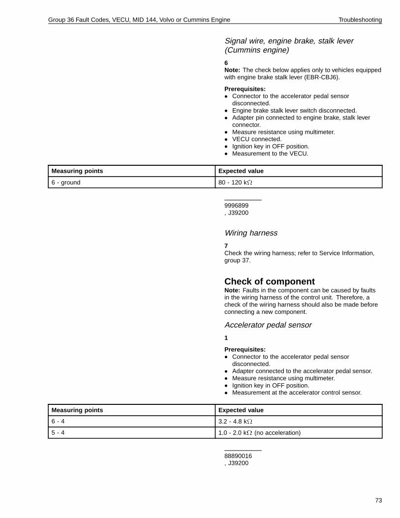
Group 36 Fault Codes, VECU, MID 144, Volvo or Cummins Engine Troubleshooting
Signal wire, engine brake, stalk lever(Cummins engine)
6Note: The check below applies only to vehicles equippedwith engine brake stalk lever (EBR-CBJ6).
Prerequisites:• Connector to the accelerator pedal sensor
disconnected.• Engine brake stalk lever switch disconnected.• Adapter pin connected to engine brake, stalk lever
connector.• Measure resistance using multimeter.• VECU connected.• Ignition key in OFF position.• Measurement to the VECU.
Measuring points Expected value
6 - ground 80 - 120 k
9996899, J39200
Wiring harness
7Check the wiring harness; refer to Service Information,group 37.
Check of componentNote: Faults in the component can be caused by faultsin the wiring harness of the control unit. Therefore, acheck of the wiring harness should also be made beforeconnecting a new component.
Accelerator pedal sensor
1
Prerequisites:• Connector to the accelerator pedal sensor
disconnected.• Adapter connected to the accelerator pedal sensor.• Measure resistance using multimeter.• Ignition key in OFF position.• Measurement at the accelerator control sensor.
Measuring points Expected value
6 - 4 3.2 - 4.8 k
5 - 4 1.0 - 2.0 k (no acceleration)
88890016, J39200
73

Group 36 Fault Codes, VECU, MID 144, Volvo or Cummins Engine Troubleshooting
Switch for engine brake stalk lever (Cumminsengine)
2Note: The check below applies only to vehicles equippedwith engine brake stalk lever (EBR-CBJ6).
Prerequisites:• Connector to engine brake switch disconnected.• Measurement box with adapter connected to engine
brake switch.• Measure resistance using multimeter.• Ignition key in OFF position.• Measurement at engine brake stalk lever.
Measuring points Expected value
1.7 - 2.5 k (pos 1)
1.3 - 2.0 k (pos 2)
1.1 - 1.7 k (pos 3)
0.9 - 1.4 k (pos 4)
0.8 - 1.2 k (pos 5)
4 - 5
0.7 - 1.1 k (pos 6)
1.0 - 1.4 k (pos 1)
0.9 - 1.3 k (pos 2)
0.8 - 1.2 k (pos 3)
0.8 - 1.1 k (pos 4)
0.7 - 1.1 k (pos 5)
6 - 5
0.7 - 1.0 k (pos 6)
J39200
Check of subsystem
Ground wire
1
Prerequisites:• Measurement box with adapter connected between
VECU connector PB and wiring harness.• Measure resistance using multimeter.• VECU connected.• Ignition key in OFF position.
Measuring points Expected value
PB22 - ground 0
9998533, 9998699, J39200
74

Group 36 Fault Codes, VECU, MID 144, Volvo or Cummins Engine Troubleshooting
Supply wire
2
Prerequisites:• Measurement box with adapter connected between
VECU connector PB and wiring harness.• Measure voltage using multimeter.• VECU connected.• Ignition key in DRIVE position.
Measuring points Expected value
PB10 - PB22 4.5 - 5.5 V
9998533, 9998699, J39200
Signal wire, accelerator pedal
3
Prerequisites:• Measurement box with adapter connected between
VECU connector PB and wiring harness.• Measure voltage using multimeter.• VECU connected.• Ignition key in DRIVE position.
Measuring points Expected value
PB8 - PB22 0.4 - 0.6 V (no acceleration)2.6 - 3.8 V (full acceleration)
9998533, 9998699, J39200
75

Group 36 Fault Codes, VECU, MID 144, Volvo or Cummins Engine Troubleshooting
Signal wire, engine brake, stalk lever(Cummins engine)
4
Prerequisites:• Measurement box with adapter connected between
VECU connector PB and wiring harness.• Measure voltage using multimeter.• VECU connected.• Ignition key in DRIVE position.
Measuring points Expected value
PB24 - PB22 0.3 - 0.7 V (pos 1)1.0 - 1.6 V (pos 2)1.7 - 2.5 V (pos 3)2.3 - 3.5 V (pos 4)2.9 - 4.4 V (pos 5)3.6 - 5.4 V (pos 6)
9998533, 9998699, J39200
VerificationUsing the PC tool, check that the fault has been corrected(see “Tests Using PC Tool” page 70).
76

Group 36 Fault Codes, VECU, MID 144, Volvo or Cummins Engine Troubleshooting
MID 144 PPID 74 VECU Power Supply
W3006775
W3006779
General InformationComponent: Rly 4 EMS power; A17, VECU; F71 Fuse,VECU power; FB01 fuse, FB05 fuse, battery 1; G01battery.
Fault code
FMI 3Abnormally high voltage or short circuit to higher voltage.
Condition for fault code:• If the voltage from relay 4, VECU pin PB15 is greater
than 1V, the VECU will interpret it as a fault and a faultcode will be set.
Possible cause:• Short-circuit to higher voltage.• Faulty relay.
Reaction from VECU:• Fault code is set.• Yellow lamp is requested.
Noticeable external symptom:• Yellow lamp lights up.
Action:• “MID 144 PPID 74 Power Supply EECU/VECU,
Check” page 78.
FMI 4Abnormally low voltage or short circuit to lower voltage.
Condition for fault code:• If the voltage from relay 4, VECU pin PB15 is less than
0V, the VECU will interpret it as a fault and a fault codewill be set.
Possible cause:• Open circuit, cable from relay.• Fault in relay.
Reaction from VECU:• Fault code is set.• Yellow lamp is requested.
Noticeable external symptom:• Yellow lamp lights up.
Action:• “MID 144 PPID 74 Power Supply EECU/VECU,
Check” page 78.
77

Group 36 Fault Codes, VECU, MID 144, Volvo or Cummins Engine Troubleshooting
3649-21-03-05MID 144 PPID 74 Power Supply EECU/VECU, Check
Special tools: 9990008, 9996899, 9998533,9998699Other special equipment: J39200
NOTE!• Read off the other fault codes for the VECU.• Switch off the current in the vehicle before the
connectors are disconnected.• Check for loose connections, switch resistance, and
oxidation. For information concerning fault tracing ofwires and connectors, refer to Service Information,group 37.
Measurement at componentconnector to VECUNote: Faults in the wiring harness to the VECUcan damage the component. Therefore, a check ofthe component should also be made if any of themeasurement values deviate.
Ground wire
1
Prerequisites:• Relay EMS disconnected• Measure resistance using multimeter.• VECU connected.• Ignition key in OFF position.• Measurement to the VECU.
Measuring points Expected value
85 - ground 0.5 M
9990008J39200
Wiring harness
2Check the wiring harness; refer to Service Information,group 37.
Check of componentNote: Faults in the component can be caused by faultsin the wiring harness of the control unit. Therefore, acheck of the wiring harness should also be made beforeconnecting a new component.
78
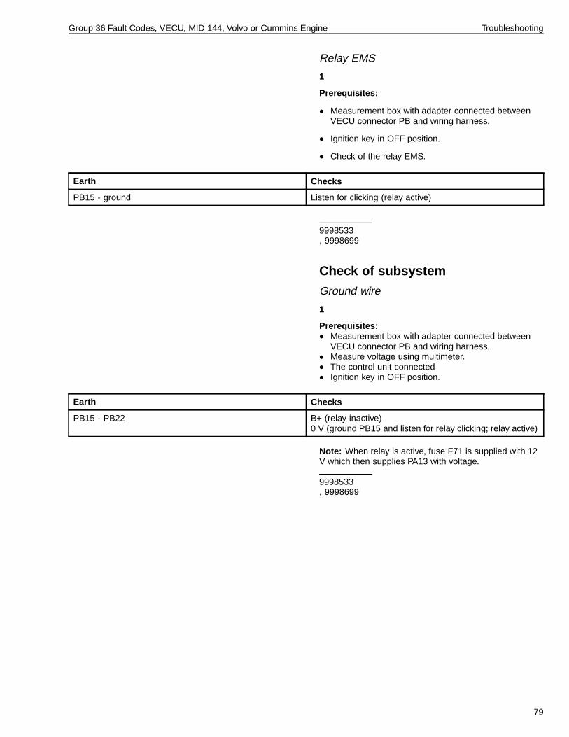
Group 36 Fault Codes, VECU, MID 144, Volvo or Cummins Engine Troubleshooting
Relay EMS
1
Prerequisites:
• Measurement box with adapter connected betweenVECU connector PB and wiring harness.
• Ignition key in OFF position.
• Check of the relay EMS.
Earth Checks
PB15 - ground Listen for clicking (relay active)
9998533, 9998699
Check of subsystem
Ground wire
1
Prerequisites:• Measurement box with adapter connected between
VECU connector PB and wiring harness.• Measure voltage using multimeter.• The control unit connected• Ignition key in OFF position.
Earth Checks
PB15 - PB22 B+ (relay inactive)0 V (ground PB15 and listen for relay clicking; relay active)
Note: When relay is active, fuse F71 is supplied with 12V which then supplies PA13 with voltage.
9998533, 9998699
79

Group 36 Fault Codes, VECU, MID 144, Volvo or Cummins Engine Troubleshooting
MID 144 SID 230 Idle Validation Switch 1
W3006772
W3006780
General Information
Component: B25 Sensor, accelerator pedal; A17, VECU
Fault code
FMI 7Incorrect response from mechanical system.
Conditions for fault code:• If the signal from the idling switch is not available in the
interval 0 - 13 %, the control unit interprets this as afault and a fault code is set.
Possible cause:• Open circuit, supply cable.• Open circuit, signal cable.• Signal cable short-circuited to ground.• Signal cable short-circuited to voltage.• Faulty switch.• Switch resistance and oxidation.
Reaction from VECU:• Fault code is set.• Yellow lamp is requested.
Noticeable external symptom:• Yellow lamp lights up.• Engine does not respond to full acceleration.
Action:• “MID 144 SID 230 Idle Validation Switch 1, Check”
page 81.
80

Group 36 Fault Codes, VECU, MID 144, Volvo or Cummins Engine Troubleshooting
3649-21-03-18MID 144 SID 230 Idle Validation Switch 1, Check
Special tools: 88890016Other special equipment: J39200
NOTE!• Read off the other fault codes for the VECU.• Switch off the current in the vehicle before the
connectors are disconnected.• Check for loose connections, switch resistance, and
oxidation. For information concerning fault tracing ofwires and connectors, refer to Service Information,group 37.
Tests Using PC ToolThe following tests are useful for closely examining thecomponent’s function:
• Accelerator pedal switches and sensors, test
• MID 144 pinout test
Measurement at componentconnector to VECUNote: Faults in the wiring harness to the VECUcan damage the component. Therefore, a check ofthe component should also be made if any of themeasurement values deviate.
Supply wire
1
Prerequisites:• Connector to the accelerator pedal sensor
disconnected.• Measurement box with adapter connected to the
VECU.• The following other pedal connectors disconnected:
• The brake pedal switch (two sockets).• The clutch pedal switch (if equipped).
• Measure voltage using multimeter.• VECU connected.• Ignition key in DRIVE position.• Measurement to the VECU.
Measuring points Expected value
3 - ground B+
88890016, J39200
81

Group 36 Fault Codes, VECU, MID 144, Volvo or Cummins Engine Troubleshooting
Signal wire
2
Prerequisites:• Connector to the accelerator pedal sensor
disconnected.• Measurement box with adapter connected to VECU.• Measure resistance using multimeter.• VECU connected.• Ignition key in OFF position.• Measurement to the VECU.
Measuring points Expected value
1 - ground 2.1 - 3.1 k
88890016, J39200
Wiring harness
3Check the wiring harness; refer to Service Information,group 37.
Check of componentNote: Faults in the component can be caused by faultsin the wiring harness to the control unit. Therefore, acheck of the wiring harness also should be made beforeconnecting a new component.
Idle validation switch 1
1
Prerequisites:• Connector to the accelerator pedal sensor
disconnected.• Measurement box with adapter connected to the
accelerator pedal sensor.• Measure resistance using multimeter.• Ignition key in OFF position.• Measurement at the accelerator pedal sensor.
Measuring points Expected value
1 - 3 ∞ (pedal at idle)20 - 90 (pedal off idle)
88890016, J39200
82

Group 36 Fault Codes, VECU, MID 144, Volvo or Cummins Engine Troubleshooting
MID 144 SID 231 J1939 Control LinkGeneral InformationThe system’s control signals are sent via J1939 ControlData Link.
Information and diagnostic signals are sent viaJ1587/1708 Information Data Link. The link also functionsas a reserve system for the J1939, if the Control DataLink does not function for any reason.
Component: A17, VECU
83

Group 36 Fault Codes, VECU, MID 144, Volvo or Cummins Engine Troubleshooting
Fault code
FMI 2Intermittent or incorrect data.
Note: Connection of the measurement box and adapterto the VECU’s "PA" connector may result in a ’ghost’fault code (SID231 / FMI 2) resulting from the adapter’seffect on the J1939 CAN_2 link (pins PA-15 and PA-16).If the fault was not present before connection of themeasurement box, ignore the code and erase all inactivefault codes following testing.
Conditions for fault code:• If the VECU does not receive confirmation for the
messages on the control link, the control unit interpretsthis as a fault and a fault code is set.
Possible cause:• Loose connection.• Open circuit, the control link.• Switch resistance and oxidation.
Reaction from VECU:• Fault code is set.• Yellow lamp is requested.
Noticeable external symptom:• Yellow lamp lights up.
Action:• Troubleshoot J1939 Control Data Link; refer to Service
Information, group 37.
FMI 12Faulty unit or component.
Note: This fault code is normally not caused by errorsin the VECU.
Conditions for fault code:• If the expected messages are not available from a
control unit on the control link the VECU interprets thisas a fault and a fault code is set.
Possible cause:• Open circuit, communication cable.• Switch resistance and oxidation.
Reaction from VECU:• Fault code is set.• Yellow lamp is requested.
Noticeable external symptom:• Yellow lamp lights up.
Action:• Troubleshoot J1939 Control Data Link; refer to Service
Information, group 37.
84

Group 36 Fault Codes, VECU, MID 144, Volvo or Cummins Engine Troubleshooting
MID 144 SID 240 Program Memory
T2012704
General InformationAt start-up a checksum is calculated for the software in theVECU flash memory. This is compared with a previouslystored checksum to check that the software is correct.
Component: A17, VECU
Fault code
FMI 2Intermittent or incorrect data
Conditions for fault code:• If the checksum calculated at start-up does not agree
with the previously saved checksum, the VECUinterprets this as a fault and a fault code is set.
Possible cause:• Software fault.• Faulty memory circuit.
Reaction from VECU:• The control unit continuously restarts.
Noticeable external symptom:• Yellow lamp is lit by the instrument control unit since
the VECU does not respond to the call.• The vehicle can only be run at increased idling speed.
85

Group 36 Fault Codes, VECU, MID 144, Volvo or Cummins Engine Troubleshooting
MID 144 SID 243 Cruise Control Set Switch
W3005580
W3005540
General InformationComponent: S02 Switch unit, cruise control.
Fault code
FMI 7Incorrect response from mechanical system.
Conditions for fault code:• If the VECU receives the signals for SET+ and SET-
at the same time, the control unit interprets this as afault and a fault code is set.
Possible cause:• Signal wire short-circuited to voltage.• Faulty switch.
Reaction from VECU:• Fault code is set.• Yellow lamp is requested.
Noticeable external symptom:• Yellow lamp lights up.• The cruise control function does not work. The speed
cannot be set, but if the speed has been set previouslyit can be resumed with RESUME.
Action:• “MID 144 SID 243 Cruise Control Set Switch, Check”
page 87.
86

Group 36 Fault Codes, VECU, MID 144, Volvo or Cummins Engine Troubleshooting
3649-21-03-20MID 144 SID 243 Cruise Control Set Switch, Check
Special tools: 9990020, 9998533, 9998699Other special equipment: J39200
NOTE!• Read off the other fault codes for the VECU.• Switch off the current in the vehicle before the
connectors are disconnected.• Check for loose connections, switch resistance, and
oxidation. For information concerning fault tracing ofwires and connectors, refer to Service Information,group 37.
Tests Using PC ToolThe following tests are useful for closely examining thecomponent’s function:
• Cruise control switch, test• MID 144 pinout test
Measurement at componentconnector to VECUNote: Faults in the wiring harness to the VECUcan damage the component. Therefore, a check ofthe component should also be made if any of themeasurement values deviate.
Supply wire
1
Prerequisites:• 14–pin connector (green) to Cruise control switch
disconnected.• Measurement box with adapter connected to the
VECU.• Measuring voltage using the multimeter.• Control unit connected.• Ignition key in drive position.• Measurement to the VECU.
87

Group 36 Fault Codes, VECU, MID 144, Volvo or Cummins Engine Troubleshooting
Measuring points Expected value
1 - ground B+
9996899, 9990020, J39200
Signal wire
2
Prerequisites:• Connector to Cruise control switch disconnected.• Measurement box with adapter connected to the
VECU.• Measure resistance using multimeter.• Control unit connected.• Ignition key in OFF position.• Measurement to the VECU.
Measuring points Expected value
5 - ground 2.1 - 3.1 k (SET+)
3 - ground 2.1 - 3.1 k (RESUME)
2 - ground 2.1 - 3.1 k (ON)
4 - ground 2.1 - 3.1 k (SET- )
9996899, 9990020, J39200
Wiring harness
3Check the wiring harness; refer to Service Information,group 37.
88

Group 36 Fault Codes, VECU, MID 144, Volvo or Cummins Engine Troubleshooting
Check of componentNote: Faults in the component can be caused by faultsin the wiring harness of the control unit. Therefore, acheck of the wiring harness should also be made beforeconnecting a new component.
Signal wire, Cruise control switch
1
Prerequisites:• Connector to Cruise control switch disconnected.• Measurement box with adapter connected to the
VECU.• Measure resistance using multimeter.• Ignition key in OFF position.• Measurement at switch cruise control.
Measuring points Expected value
∞ (SET+ and SET- inactive)
∞ (ON and SET+ active)
∞ (RESUME active and SET+ active)
∞ (ON and SET- active)
5 - 4 (against switch)
∞ (RESUME active and SET- active)
9996899, 9990020, J39200
89

Group 36 Fault Codes, VECU, MID 144, Volvo or Cummins Engine Troubleshooting
Check of subsystem
Signal wire
1
Prerequisites:• Measurement box with adapter connected between
VECU connector PA and wiring harness.• Measuring voltage using the multimeter.• Control unit connected.• Ignition key in drive position.
Measuring points Expected value
B+ (OFF and SET- active)
0 V (OFF and SET+ active)
0 V (ON and SET+ active)
PA1 - PA12
0 V (RESUME active and SET+ active)
B+ (OFF and SET+ active)
0 V (OFF and SET- active)
0 V (ON and SET- active)
PA2 - PA12
0 V (RESUME active and SET- active)
9813194, 9998699, J39200
90

Group 36 Fault Codes, VECU, MID 144, Volvo or Cummins Engine Troubleshooting
MID 144 SID 250 J1587/J1708 Information Data LinkGeneral InformationThe non-critical communication between the vehicle’scontrol units and the display on the instrument’s gaugesis carried out via J1587/1708 Information Data Link.
The system’s critical control signals are sent via theJ1939 Control Data Link.
Information and diagnostic signals are sent viaJ1587/1708 Information Data Link. The link also functionsas a reserve system for the J1939 Control Data Link, ifthe Control Data Link does not function for any reason.J1587/1708 Information Data Link keeps the systemstatus continually updated and makes this informationavailable for reading via the diagnostics socket.
Component: A17, VECU.
Fault code
FMI 2Intermittent or incorrect data.
• If the VECU is unable to send it’s messages onto thedatabus after several attempts, the VECU will use thisfault code to flag a possible physical fault with thedatalink.
Conditions for fault code:• If the VECU registers incorrect messages on the
information link the control unit interprets this as a faultand a fault code is set.
Possible cause:• Several units are sending at the same time on the
information link.
Reaction from VECU:• Fault code is set.• Yellow lamp is requested.
Noticeable external symptom:• Yellow lamp lights up.
Action:• Troubleshoot J1939 Control Data Link; refer to Service
Information, group 37.
91

Group 36 Fault Codes, VECU, MID 144, Volvo or Cummins Engine Troubleshooting
MID 144 SID 253 Calibration Memory EEPROM
T2012704
General InformationAt start-up a checksum is calculated for the data set inthe control unit’s EEPROM memory. This is compared
with a previously stored checksum to check that the dataset is correct.
Fault code
FMI 2Intermittent or incorrect data.
Conditions for fault code:• If the VECU receives an error in calculating the
checksum in the calibration memory the control unitinterprets this as a fault and a fault code is set.
Possible cause:• Faulty memory circuit.• Error when programming.
Reaction from VECU:• Fault code is set.• Red lamp is requested.
Noticeable external symptom:• Red lamp lights up.• The vehicle can only be driven at increased idling
speed.
FMI 13Calibration values outside the limits.
Conditions for fault code:• If the checksum for the data set calculated at start-up
does not agree with the previously saved checksum,the VECU interprets this as a fault and a fault codeis set.
Possible cause:• Incorrect data set.• Faulty memory circuit.
Reaction from VECU:• Fault code is set.• Red lamp is requested.
Noticeable external symptom:• Red lamp lights up.• The vehicle can only be driven at increased idling
speed.
92

Group 36 Fault Codes, VECU, MID 144, Volvo or Cummins Engine Troubleshooting
MID 144 PSID 4 Engine Brake Stalk Lever(Cummins engine; applies only to EBR-CBJ6.)
T3015745
W3005544
General InformationComponent: S24 Stalk lever, engine brake A17, VECU
Fault code
FMI 3Abnormally high voltage or short circuit to higher voltage.
Conditions for fault code:• If the VECU registers a voltage higher than 4.8 V, the
control unit interprets this as a fault and a fault codeis set.
Possible cause:• Open circuit, ground cable.• Signal cable short-circuited to voltage.• Faulty switch.• Switch resistance and oxidation.
Reaction from VECU:• Fault code is set.• Yellow lamp is requested.
Noticeable external symptom:• Yellow lamp lights up.• Engine brake cannot be activated.
Action:• “MID 144 PSID 4 Engine Brake Stalk Lever, Check”
page 94.
FMI 4Abnormally low voltage or short circuit to lower voltage.
Conditions for fault code:• If the VECU interprets a voltage below 0.2 V as a fault
and a fault code is set.
Possible cause:• Open circuit, supply cable.• Open circuit, signal cable.• Signal cable short-circuited to ground.• Faulty switch.• Switch resistance and oxidation.
Reaction from VECU:• Fault code is set.• Yellow lamp is requested.
Noticeable external symptom:• Yellow lamp lights up.• Engine brake cannot be activated.
Action:• “MID 144 PSID 4 Engine Brake Stalk Lever, Check”
page 94.
93

Group 36 Fault Codes, VECU, MID 144, Volvo or Cummins Engine Troubleshooting
3649-21-03-25MID 144 PSID 4 Engine Brake Stalk Lever, Check
Special tools: 9998533, 9998699Other special equipment: J39200
NOTE!• Read off the other fault codes for the VECU.• Switch off the current in the vehicle before the
connectors are disconnected.• Check for loose connections, switch resistance, and
oxidation. For information concerning fault tracing ofwires and connectors, refer to Service Information,group 37.
Tests Using PC ToolThe following tests are useful for closely examining thecomponent’s function:
• Engine brake, function test
• MID 144 pinout test
Measurement at componentconnector to VECUNote: Faults in the wiring harness to the VECUcan damage the component. Therefore, a check ofthe component should also be made if any of themeasurement values deviate.
Note: It may be necessary to temporarily remove theconnector from its mounting location to perform thefollowing checks.
1Disconnect the connector at the switch for the enginebrake.
2Disconnect the connector at the accelerator pedal sensor.
94

Group 36 Fault Codes, VECU, MID 144, Volvo or Cummins Engine Troubleshooting
Ground wire
3
Prerequisites:• Back-probe the connector at the designed cavity.• Measure resistance using multimeter.• Control unit connected.• Ignition key in OFF position.• Measurement to the VECU.
Measuring points Expected value
5 - ground ≈ 0
9998699J39200
Supply wire
4
Prerequisites:• Back-probe the connector at the designed cavity.• Measuring voltage using the multimeter.• Control unit connected.• Ignition key in drive position.• Measurement to the VECU.
Measuring points Expected value
4 - ground ≈ 4.3 - 6.5 V
9998699J39200
Signal wire
5
Prerequisites:• Back-probe the connector at the designed cavity.• Measure resistance using multimeter.• Control unit connected.• Ignition key in OFF position.• Measurement to the VECU.
Measuring points Expected value
6 - ground 0.8 - 1.2 k
J39200
Wiring harness
6Check the wiring harness; refer to Service Information,group 37.
95
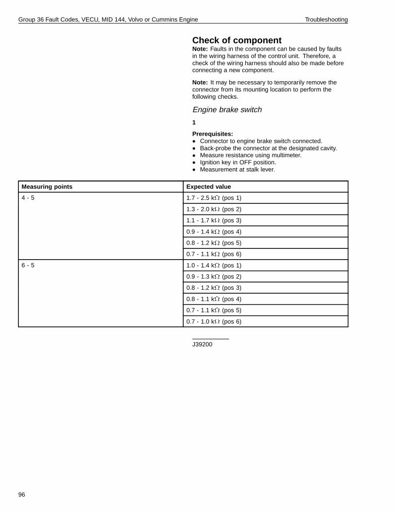
Group 36 Fault Codes, VECU, MID 144, Volvo or Cummins Engine Troubleshooting
Check of componentNote: Faults in the component can be caused by faultsin the wiring harness of the control unit. Therefore, acheck of the wiring harness should also be made beforeconnecting a new component.
Note: It may be necessary to temporarily remove theconnector from its mounting location to perform thefollowing checks.
Engine brake switch
1
Prerequisites:• Connector to engine brake switch connected.• Back-probe the connector at the designated cavity.• Measure resistance using multimeter.• Ignition key in OFF position.• Measurement at stalk lever.
Measuring points Expected value
1.7 - 2.5 k (pos 1)
1.3 - 2.0 k (pos 2)
1.1 - 1.7 k (pos 3)
0.9 - 1.4 k (pos 4)
0.8 - 1.2 k (pos 5)
4 - 5
0.7 - 1.1 k (pos 6)
1.0 - 1.4 k (pos 1)
0.9 - 1.3 k (pos 2)
0.8 - 1.2 k (pos 3)
0.8 - 1.1 k (pos 4)
0.7 - 1.1 k (pos 5)
6 - 5
0.7 - 1.0 k (pos 6)
J39200
96

Group 36 Fault Codes, VECU, MID 144, Volvo or Cummins Engine Troubleshooting
Check of subsystem
Ground wire
1
Prerequisites:• Measurement box with adapter connected between
VECU connector PB and wiring harness.• Measuring resistance using multimeter.• Control unit connected.• Ignition key in OFF position.
Measuring points Expected value
PB22 - ground ≈ 0
9998533, 9998699J39200
Supply wire
2
Prerequisites:• Measurement box with adapter connected between
VECU connector PB and wiring harness.• Measuring voltage using multimeter.• Control unit connected.• Ignition key in DRIVE position.
Measuring points Expected value
PB10 - PB22 ≈ 4 - 6 V
9998533, 9998699J39200
97

Group 36 Fault Codes, VECU, MID 144, Volvo or Cummins Engine Troubleshooting
Signal wire
3
Prerequisites:• Measurement box with adapter connected between
VECU connector PB and wiring harness.• Measuring voltage using multimeter.• Control unit connected.• Ignition key in DRIVE position.
Measuring points Expected value
0.3 - 0.7 V (pos 1)
1.0 - 1.6 V (pos 2)
1.7 - 2.5 V (pos 3)
2.3 - 3.5 V (pos 4)
2.9 - 4.4 V (pos 5)
PB24 - PB22
3.6 - 5.4 V (pos 6)
9998533, 9998699J39200
VerificationUsing the PC tool, check that the fault has been corrected(see “Tests Using PC Tool” page 94).
98

Group 36 Fault Codes, VECU, MID 144, Volvo or Cummins Engine Troubleshooting
MID 144 PSID 200 J1939 Control Data Link Interruption, Engine ECUGeneral InformationThe control units share important information on theJ1939 Control Data Link. If a control unit lacks messagesfrom another control unit, this fault code will be usedto point out the control unit that is expected to sendmessages on the J1939 Control Data Link.
Fault code
FMI 9Abnormal updating rate.
Condition for fault code:• If the VECU does not receive any messages on the
J1939 Control Data Link from the EECU within acertain time, the control unit will interpret this as a faultand a fault code is set.
Possible cause:• Fault in J1939 Control Data Link between EMS control
unit and VECU
Reaction from VECU:• Yellow lamp requested.
Noticeable external symptom:• Yellow lamp lights up.
Action:• Troubleshoot J1939 Control Data Link; refer to Service
Information, group 37.
99

Group 36 Fault Codes, VECU, MID 144, Volvo or Cummins Engine Troubleshooting
MID 144 PSID 202 J1939 Control Data Link Interruption, Instrument
Control UnitGeneral InformationThe control units share important information on theJ1939 Control Data Link. If a control unit lacks messagesfrom another control unit, this fault code will be usedto point out the control unit that is expected to sendmessages on the J1939 Control Data Link.
Fault code
FMI 9Abnormal updating rate.
Condition for fault code:• If the VECU does not receive any messages
concerning time/date on the J1939 Control Data Linkfrom the instrument within a certain time, the controlunit will interpret this as a fault and a fault code is set.
Possible cause:• Fault in J1939 Control Data Link between instrument
and VECU
Reaction from VECU:• Yellow information lamp requested.
Noticeable external symptom:• Yellow lamp lights up.
Action:• Troubleshoot J1939 Control Data Link; refer to Service
Information, group 37.
100

Group 36 Fault Codes, VECU, MID 144, Volvo or Cummins Engine Troubleshooting
MID 144 PSID 204 J1939 Control Data Link Interruption, Brake
Control UnitGeneral InformationThe control units share important information on theJ1939 Control Data Link. If a control unit lacks messagesfrom another control unit, this fault code will be usedto point out the control unit that is expected to sendmessages on the J1939 Control Data Link.
Fault code
FMI 9Abnormal updating rate.
Condition for fault code:• If the VECU does not receive any messages on the
J1939 Control Data Link from the brake control unitwithin a certain time, the control unit will interpret thisas a fault and a fault code is set.
Possible cause:• Fault in J1939 Control Data Link between ABS/EBS
control unit and VECU
Reaction from VECU:• Yellow lamp requested.
Noticeable external symptom:• Yellow lamp lights up.
Action:• Troubleshoot J1939 Control Data Link; refer to Service
Information, group 37.
101

Group 36 Fault Codes, VECU, MID 144, Volvo or Cummins Engine Troubleshooting
MID 144 PSID 210 J1939 Control Data Link Interruption, Lighting
Control Module (LCM)General InformationThe control units share important information on theJ1939 Control Data Link. If a control unit lacks messagesfrom another control unit, this fault code will be usedto point out the control unit that is expected to sendmessages on the J1939 Control Data Link.
Fault code
FMI 9Abnormal updating rate.
Condition for fault code:• If the VECU does not receive any messages on the
J1939 Control Data Link from the light control modulewithin a certain time, the control unit will interpret thisas a fault and a fault code is set.
Possible cause:• Fault in J1939 Control Data Link between LCM control
unit and VECU
Reaction from VECU:• Yellow lamp requested.
Noticeable external symptom:• Yellow lamp lights up.
Action:• Troubleshoot J1939 Control Data Link; refer to Service
Information, group 37.
102
Group 36 Fault Codes, VECU, MID 144, Volvo or Cummins Engine Troubleshooting
MID 144 PSID 214 J1939 Control Data Link Interruption, Bodybuilder
Control Unit(Volvo engines only)
General InformationThe control units share important information on theJ1939 Control Data Link. If a control unit lacks messagesfrom another control unit, this fault code will be usedto point out the control unit that is expected to sendmessages on the J1939 Control Data Link.
Fault code
FMI 9Abnormal updating rate.
Condition for fault code:• If the VECU does not receive any messages on the
J1939 Control Data Link from the bodybuilder modulewithin a certain time, the control unit will interpret thisas a fault and a fault code is set.
Possible cause:• Fault in J1939 Control Data Link between BBM control
unit and VECU
Reaction from VECU:• Yellow lamp requested.
Noticeable external symptom:• Yellow lamp lights up.
Action:• Troubleshoot J1939 Control Data Link; refer to Service
Information, group 37.
103

Group 36 Fault Codes, VECU, MID 144, Volvo or Cummins Engine Troubleshooting
MID 144 SID 231 J1939 Control LinkGeneral InformationInternal resets are a normal function of the VECU and areclosely monitored and reported when a problem exists.This reset can be due to either an internal or externalproblem.
Fault Code
FMI 4 Abnormally low voltage or short circuit to lower voltage
Condition for fault code:•
If the VECU detects an abnormal reset the control unitwill interpret this as an error and a fault code is set.
Possible cause:• Inconsistent power supplied to the VECU (EMS relay)• Poor ground circuitry to the VECU
Reaction from VECU:• Yellow lamp requested
Noticeable external symptom:• Yellow lamp in cluster• Fault code is set
Actions:• Check the power supply circuit(s) to the VECU for
uninterrupted battery voltage• Check for: (Damaged wiring, loose connections at
connectors/splices, loose/bent pins, corrosion, etc.)• Check the ground circuit for good continuity• Check for: (Damaged wiring, loose connections at
connectors/splices, loose/bent pins, corrosion, etc.)
FMI 12 Abnormal Reset
Condition for fault code:•
If the VECU detects an abnormal reset the control unitwill interpret this as an error and a fault code is set.
Possible cause:•
Possible software failure
Possible hardware failure Reaction from VECU:• Yellow lamp requested• Yellow lamp in cluster
Noticeable external symptom:• Fault code is set
Actions:• Replace the VECU’s main software using VCADS Pro
(Do this first before replacing the VECU to see if thisresolves the problem)
• Replace the VECU control unit (Do this last after allother checks have been exhausted)
104

Operation Numbers
3649-21-03-08 MID 144 PID 84 Vehicle Speed, Check ................................................................................................... 23
3649-21-03-09 MID 144 PID 91 Accelerator Pedal Position (Percentage), Check ........................................................... 28
3649-21-03-01 MID 144 PID 150 PTO Output, Check ..................................................................................................... 34
3649-21-03-28 MID 144 PID 191 Output Shaft Speed, Check ......................................................................................... 40
3649-21-03-04 MID 144 PPID 61 Engine Brake Switch, Check ....................................................................................... 45
3649-21-03-10 MID 144 PPID 69 Buffered Idle Validation Switch, Check ....................................................................... 49
3649-21-03-11 MID 144 PPID 70 Pedal Switches, Supply, Check ................................................................................... 52
3649-21-03-12 MID 144 PPID 71 Cruise Control and Engine Brake, Switch Supply, Check ........................................... 61
3649-21-03-13 MID 144 PPID 72 Accelerator Pedal and Engine Brake, Sensors Supply, Check ................................... 70
3649-21-03-05 MID 144 PPID 74 Power Supply EECU/VECU, Check ............................................................................ 78
3649-21-03-18 MID 144 SID 230 Idle Validation Switch 1, Check ................................................................................... 81
3649-21-03-20 MID 144 SID 243 Cruise Control Set Switch, Check ............................................................................... 87
3649-21-03-25 MID 144 PSID 4 Engine Brake Stalk Lever, Check .................................................................................. 94


Volvo Trucks North America, Inc.P.O. Box 26115, Greensboro, NC 27402-6115
Volvo Trucks Canada, Ltd.5600A Cancross Court, Mississauga, Ontario L5R 3E9
http://www.volvotrucks.volvo.com
PV776-20 033671 (USA) 08.2005 © Volvo Trucks North America, Inc., 2005