Embed Size (px)
Citation preview
GROUP 23B
CONTINUOUSLY VARIABLE
TRANSMISSION OVERHAUL
CONTENTS
GENERAL INFORMATION . . . . . . . . 23B-2
GENERAL SPECIFICATIONS. . . . . . 23B-4
SERVICE SPECIFICATIONS. . . . . . . 23B-4
VALVE BODY SPRING IDENTIFICATION TABLE . . . . . . . . . 23B-4
SNAP RING, SPACER AND THRUST WASHER FOR ADJUSTMENT . . . . . 23B-5
TORQUE SPECIFICATIONS . . . . . . . 23B-6
SEALANTS . . . . . . . . . . . . . . . . . . . . 23B-7
SPECIAL TOOLS. . . . . . . . . . . . . . . . 23B-8
TRANSMISSION. . . . . . . . . . . . . . . . . 23B-10DISASSEMBLY AND REASSEMBLY . . . . . 23B-10ADJUSTMENT OF TRANSMISSION . . . . . 23B-29
FORWARD CLUTCH . . . . . . . . . . . . . 23B-31DISASSEMBLY AND REASSEMBLY . . . . . 23B-31
REVERSE BRAKE . . . . . . . . . . . . . . . 23B-34DISASSEMBLY AND REASSEMBLY . . . . . 23B-34
VALVE BODY . . . . . . . . . . . . . . . . . . . 23B-36DISASSEMBLY AND REASSEMBLY . . . . . 23B-36
OUTPUT SHAFT. . . . . . . . . . . . . . . . . 23B-40DISASSEMBLY AND REASSEMBLY . . . . . 23B-40
DIFFERENTIAL. . . . . . . . . . . . . . . . . . 23B-42DISASSEMBLY AND REASSEMBLY . . . . . 23B-42

GENERAL INFORMATIONCONTINUOUSLY VARIABLE TRANSMISSION OVERHAUL23B-2
GENERAL INFORMATIONM1233200100140
AUTOMATIC TRANSMISSION MODELSTransmission model Combined engine Vehicle modelF1C1A-1-L2Z 4A91 D4 MIVEC Z23A
GENERAL INFORMATIONCONTINUOUSLY VARIABLE TRANSMISSION OVERHAUL 23B-3
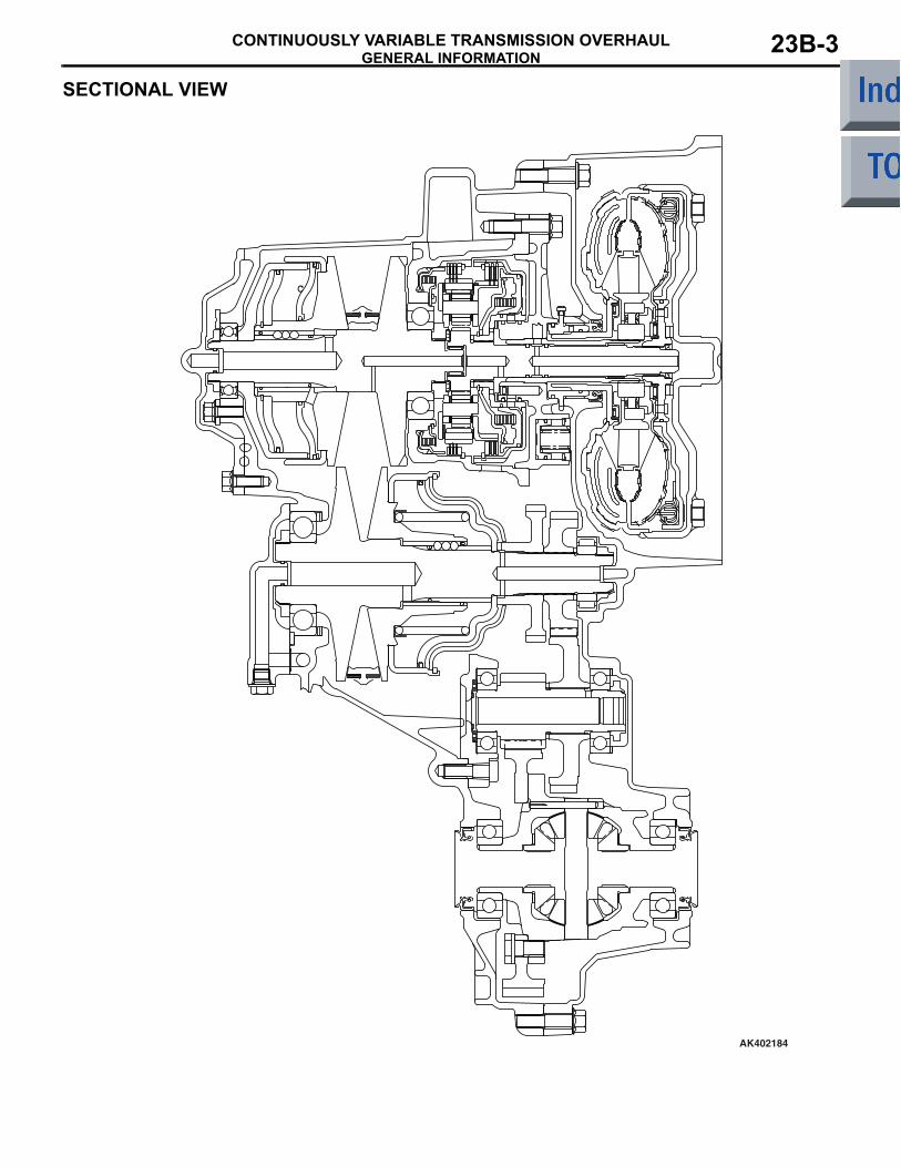
SECTIONAL VIEW
�c
AK402184
GENERAL SPECIFICATIONSCONTINUOUSLY VARIABLE TRANSMISSION OVERHAUL23B-4
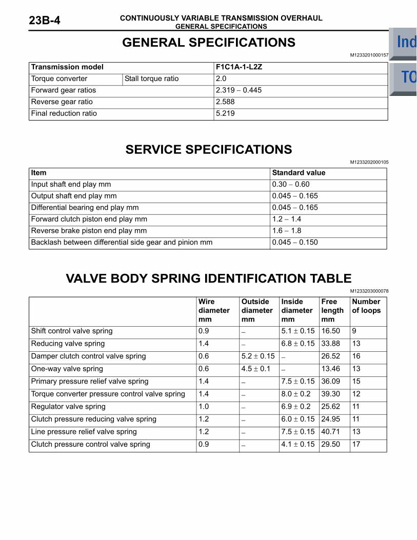
GENERAL SPECIFICATIONSM1233201000157
Transmission model F1C1A-1-L2ZTorque converter Stall torque ratio 2.0Forward gear ratios 2.319 − 0.445Reverse gear ratio 2.588Final reduction ratio 5.219
SERVICE SPECIFICATIONSM1233202000105
Item Standard valueInput shaft end play mm 0.30 − 0.60Output shaft end play mm 0.045 − 0.165Differential bearing end play mm 0.045 − 0.165Forward clutch piston end play mm 1.2 − 1.4Reverse brake piston end play mm 1.6 − 1.8Backlash between differential side gear and pinion mm 0.045 − 0.150
VALVE BODY SPRING IDENTIFICATION TABLEM1233203000078
Wire diametermm
Outside diametermm
Inside diametermm
Free lengthmm
Number of loops
Shift control valve spring 0.9 − 5.1 ± 0.15 16.50 9
Reducing valve spring 1.4 − 6.8 ± 0.15 33.88 13
Damper clutch control valve spring 0.6 5.2 ± 0.15 − 26.52 16
One-way valve spring 0.6 4.5 ± 0.1 − 13.46 13
Primary pressure relief valve spring 1.4 − 7.5 ± 0.15 36.09 15
Torque converter pressure control valve spring 1.4 − 8.0 ± 0.2 39.30 12
Regulator valve spring 1.0 − 6.9 ± 0.2 25.62 11
Clutch pressure reducing valve spring 1.2 − 6.0 ± 0.15 24.95 11
Line pressure relief valve spring 1.2 − 7.5 ± 0.15 40.71 13
Clutch pressure control valve spring 0.9 − 4.1 ± 0.15 29.50 17
SNAP RING, SPACER AND THRUST WASHER FOR ADJUSTMENTCONTINUOUSLY VARIABLE TRANSMISSION OVERHAUL 23B-5
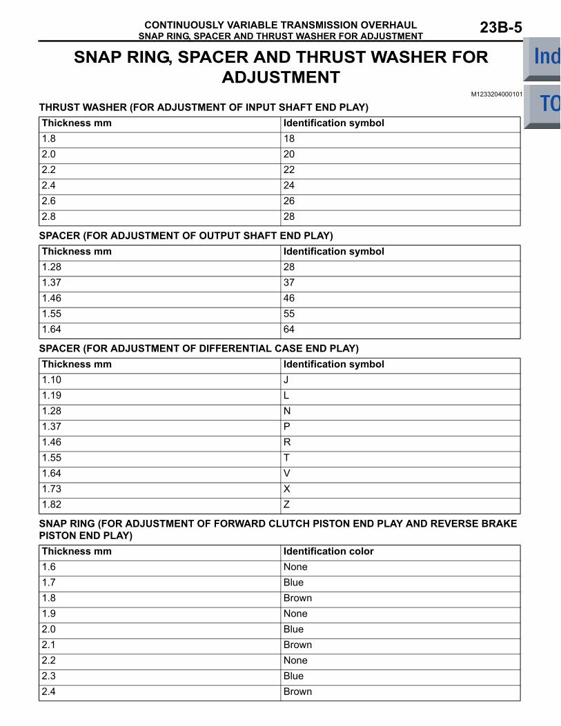
SNAP RING, SPACER AND THRUST WASHER FOR ADJUSTMENT
M1233204000101
THRUST WASHER (FOR ADJUSTMENT OF INPUT SHAFT END PLAY) Thickness mm Identification symbol1.8 182.0 202.2 222.4 242.6 262.8 28
SPACER (FOR ADJUSTMENT OF OUTPUT SHAFT END PLAY)Thickness mm Identification symbol1.28 281.37 371.46 461.55 551.64 64
SPACER (FOR ADJUSTMENT OF DIFFERENTIAL CASE END PLAY)Thickness mm Identification symbol1.10 J1.19 L1.28 N1.37 P1.46 R1.55 T1.64 V1.73 X1.82 Z
SNAP RING (FOR ADJUSTMENT OF FORWARD CLUTCH PISTON END PLAY AND REVERSE BRAKE PISTON END PLAY)Thickness mm Identification color1.6 None1.7 Blue1.8 Brown1.9 None2.0 Blue2.1 Brown2.2 None2.3 Blue2.4 Brown
TORQUE SPECIFICATIONSCONTINUOUSLY VARIABLE TRANSMISSION OVERHAUL23B-6
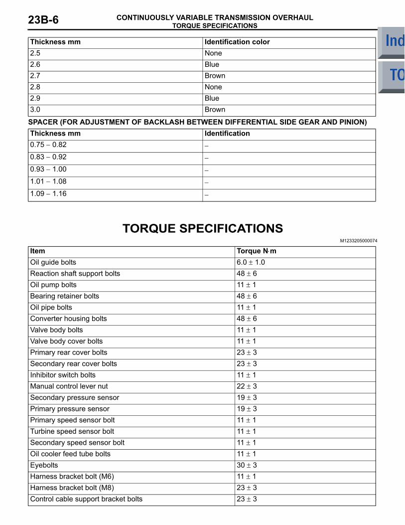
SPACER (FOR ADJUSTMENT OF BACKLASH BETWEEN DIFFERENTIAL SIDE GEAR AND PINION)Thickness mm Identification0.75 − 0.82 −
0.83 − 0.92 −
0.93 − 1.00 −
1.01 − 1.08 −
1.09 − 1.16 −
TORQUE SPECIFICATIONSM1233205000074
Item Torque N⋅mOil guide bolts 6.0 ± 1.0Reaction shaft support bolts 48 ± 6Oil pump bolts 11 ± 1Bearing retainer bolts 48 ± 6Oil pipe bolts 11 ± 1Converter housing bolts 48 ± 6Valve body bolts 11 ± 1Valve body cover bolts 11 ± 1Primary rear cover bolts 23 ± 3Secondary rear cover bolts 23 ± 3Inhibitor switch bolts 11 ± 1Manual control lever nut 22 ± 3Secondary pressure sensor 19 ± 3Primary pressure sensor 19 ± 3Primary speed sensor bolt 11 ± 1Turbine speed sensor bolt 11 ± 1Secondary speed sensor bolt 11 ± 1Oil cooler feed tube bolts 11 ± 1Eyebolts 30 ± 3Harness bracket bolt (M6) 11 ± 1Harness bracket bolt (M8) 23 ± 3Control cable support bracket bolts 23 ± 3
2.5 None2.6 Blue2.7 Brown2.8 None2.9 Blue3.0 Brown
Thickness mm Identification color
SEALANTSCONTINUOUSLY VARIABLE TRANSMISSION OVERHAUL 23B-7
Outside valve body bolts 11 ± 1Solenoid valve bolts 6.0 ± 1.0Adjusting screw assembly bolts 6.0 ± 1.0Inside separating plate bolts 6.0 ± 1.0Detent spring bolt 6.0 ± 1.0Output shaft lock nut 190 ± 20Differential drive gear mounting bolts 135 ± 5
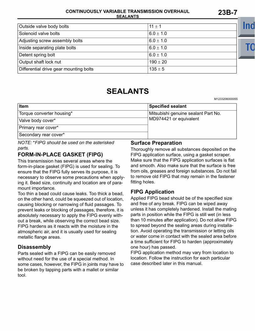
SEALANTSM1233206000055
Item Specified sealantTorque converter housing* Mitsubishi genuine sealant Part No.
MD974421 or equivalentValve body cover*Primary rear cover*Secondary rear cover*
NOTE: *FIPG should be used on the asterisked parts.FORM-IN-PLACE GASKET (FIPG)This transmission has several areas where the form-in-place gasket (FIPG) is used for sealing. To ensure that the FIPG fully serves its purpose, it is necessary to observe some precautions when apply-ing it. Bead size, continuity and location are of para-mount importance. Too thin a bead could cause leaks. Too thick a bead, on the other hand, could be squeezed out of location, causing blocking or narrowing of fluid passages. To prevent leaks or blocking of passages, therefore, it is absolutely necessary to apply the FIPG evenly with-out a break, while observing the correct bead size.FIPG hardens as it reacts with the moisture in the atmospheric air, and it is usually used for sealing metallic flange areas.
DisassemblyParts sealed with a FIPG can be easily removed without need for the use of a special method. In some cases, however, the FIPG in joints may have to be broken by tapping parts with a mallet or similar tool.
Surface PreparationThoroughly remove all substances deposited on the FIPG application surface, using a gasket scraper. Make sure that the FIPG application surfaces is flat and smooth. Also make sure that the surface is free from oils, greases and foreign substances. Do not fail to remove old FIPG that may remain in the fastener fitting holes.
FIPG ApplicationApplied FIPG bead should be of the specified size and free of any break. FIPG can be wiped away unless it has completely hardened. Install the mating parts in position while the FIPG is still wet (in less than 10 minutes after application). Do not allow FIPG to spread beyond the sealing areas during installa-tion. Avoid operating the transmission or letting oils or water come in contact with the sealed area before a time sufficient for FIPG to harden (approximately one hour) has passed. FIPG application method may vary from location to location. Follow the instruction for each particular case described later in this manual.
SPECIAL TOOLSCONTINUOUSLY VARIABLE TRANSMISSION OVERHAUL23B-8
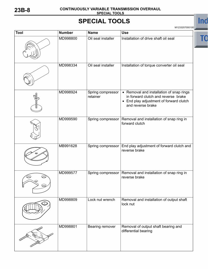
SPECIAL TOOLSM1233207000100
Tool Number Name UseMD998800 Oil seal installer Installation of drive shaft oil seal
MD998334 Oil seal installer Installation of torque converter oil seal
MD998924 Spring compressor retainer
• Removal and installation of snap rings in forward clutch and reverse brake
• End play adjustment of forward clutch and reverse brake
MD999590 Spring compressor Removal and installation of snap ring in forward clutch
MB991628 Spring compressor End play adjustment of forward clutch and reverse brake
MD999577 Spring compressor Removal and installation of snap ring in reverse brake
MD998809 Lock nut wrench Removal and installation of output shaft lock nut
MD998801 Bearing remover Removal of output shaft bearing and differential bearing
SPECIAL TOOLSCONTINUOUSLY VARIABLE TRANSMISSION OVERHAUL 23B-9
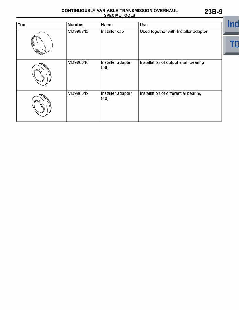
MD998812 Installer cap Used together with Installer adapter
MD998818 Installer adapter (38)
Installation of output shaft bearing
MD998819 Installer adapter (40)
Installation of differential bearing
Tool Number Name Use
TRANSMISSIONCONTINUOUSLY VARIABLE TRANSMISSION OVERHAUL23B-10
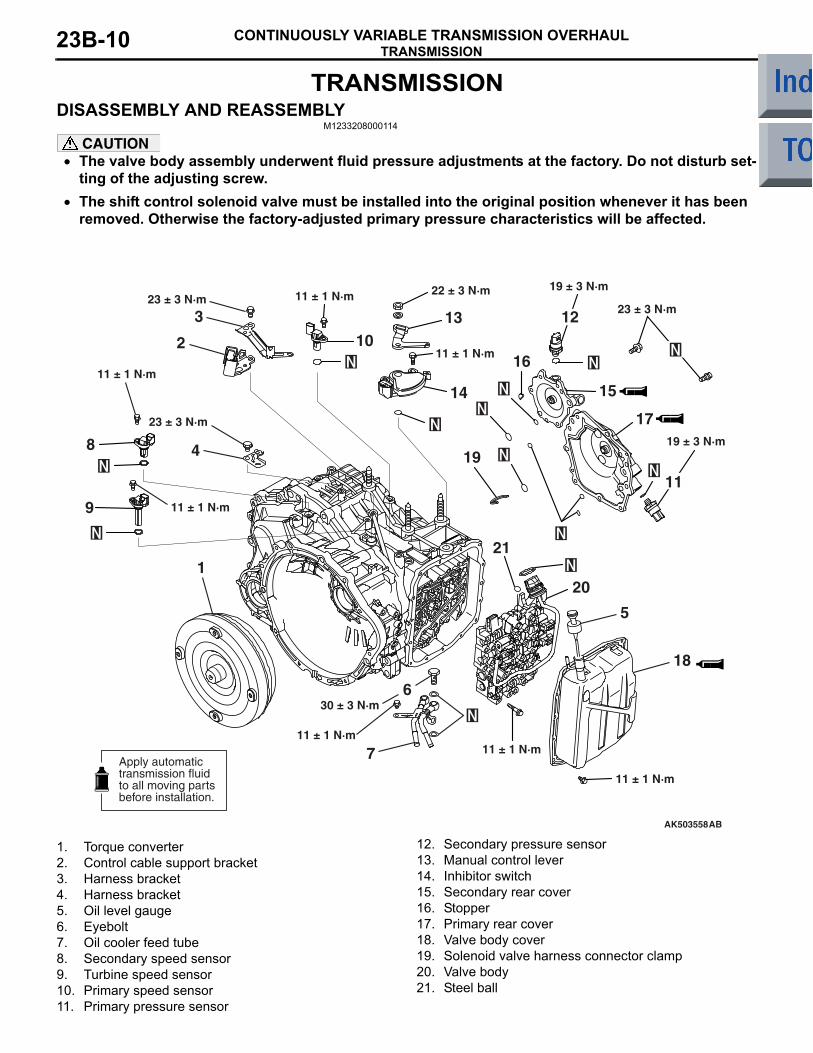
TRANSMISSIONDISASSEMBLY AND REASSEMBLY
M1233208000114
CAUTION• The valve body assembly underwent fluid pressure adjustments at the factory. Do not disturb set-
ting of the adjusting screw.•
AK503558
11 ± 1 N·m11 ± 1 N·m
11 ± 1 N·m
11 ± 1 N·m
11 ± 1 N·m
19 ± 3 N·m
30 ± 3 N·m
23 ± 3 N·m23 ± 3 N·m3
2
4
6
8
9
16
17
10
11 ± 1 N·m
1
13
14
22 ± 3 N·m
15
11 ± 1 N·m
20
19
21
23 ± 3 N·m
5
18
7
AB
11
19 ± 3 N·m
12
Apply automatictransmission fluidto all moving partsbefore installation.
1. Torque converter2. Control cable support bracket3. Harness bracket4. Harness bracket5. Oil level gauge6. Eyebolt7. Oil cooler feed tube8. Secondary speed sensor9. Turbine speed sensor10. Primary speed sensor11. Primary pressure sensor
12. Secondary pressure sensor13. Manual control lever14. Inhibitor switch15. Secondary rear cover16. Stopper17. Primary rear cover18. Valve body cover19. Solenoid valve harness connector clamp20. Valve body21. Steel ball
The shift control solenoid valve must be installed into the original position whenever it has been removed. Otherwise the factory-adjusted primary pressure characteristics will be affected.
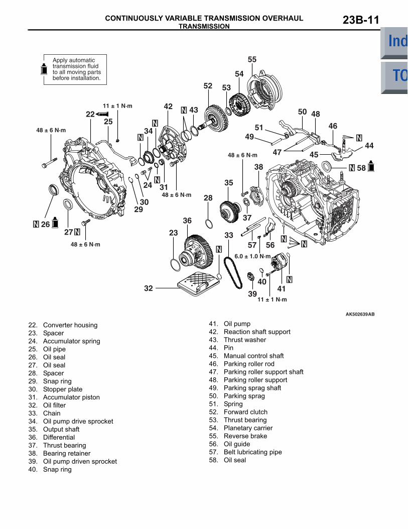
TRANSMISSIONCONTINUOUSLY VARIABLE TRANSMISSION OVERHAUL 23B-11
AK502639
6.0 ± 1.0 N·m
11 ± 1 N·m
48 ± 6 N·m
48 ± 6 N·m
48 ± 6 N·m
48 ± 6 N·m
11 ± 1 N·m
56
23
41
36
35
4951
50 48
46
444547
38
28
53
34
42 43
32
54
5733
39
40
55
52
2225
24 31
27
AB
2930
37
Apply automatictransmission fluidto all moving partsbefore installation.
58
26
22. Converter housing23. Spacer24. Accumulator spring25. Oil pipe26. Oil seal27. Oil seal28. Spacer29. Snap ring30. Stopper plate31. Accumulator piston32. Oil filter33. Chain34. Oil pump drive sprocket35. Output shaft36. Differential37. Thrust bearing38. Bearing retainer39. Oil pump driven sprocket40. Snap ring
41. Oil pump42. Reaction shaft support43. Thrust washer44. Pin45. Manual control shaft46. Parking roller rod47. Parking roller support shaft48. Parking roller support49. Parking sprag shaft50. Parking sprag51. Spring52. Forward clutch53. Thrust bearing54. Planetary carrier55. Reverse brake56. Oil guide57. Belt lubricating pipe58. Oil seal
TRANSMISSIONCONTINUOUSLY VARIABLE TRANSMISSION OVERHAUL23B-12
DISASSEMBLY SERVICE POINTS
CAUTION• The automatic transmission includes many
high-precision components. All parts must be handled carefully not to give damage to them when the transmission is disassembled and reassembled.
• Place a rubber mat over the bench on which disassembly work is going to be performed. Always keep the mat surface clean.
• Do not use cotton gloves and shop towel or rag when disassembling the transmission. Use nylon gloves or paper towel if necessary.
• All removed parts must be washed. Metal parts may be washed in solvent but must be dried using compressed air after washing.
• Wash the clutch discs, brake discs, plastic thrust plates and rubber parts in automatic transmission fluid (ATF). Keep the washed parts away from dust.
• Whenever transmission parts are found dam-aged, the oil cooler system components must be disassembled and washed.
AK401999
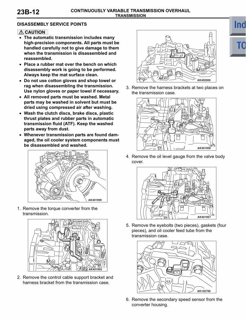
1. Remove the torque converter from the transmission.
AK401955
2. Remove the control cable support bracket and harness bracket from the transmission case.
AK402000
3. Remove the harness brackets at two places on the transmission case.
AK401956
4. Remove the oil level gauge from the valve body cover.
AK401957
5. Remove the eyebolts (two pieces), gaskets (four pieces), and oil cooler feed tube from the transmission case.
AK102790
6. Remove the secondary speed sensor from the converter housing.
TRANSMISSIONCONTINUOUSLY VARIABLE TRANSMISSION OVERHAUL 23B-13
AK102789
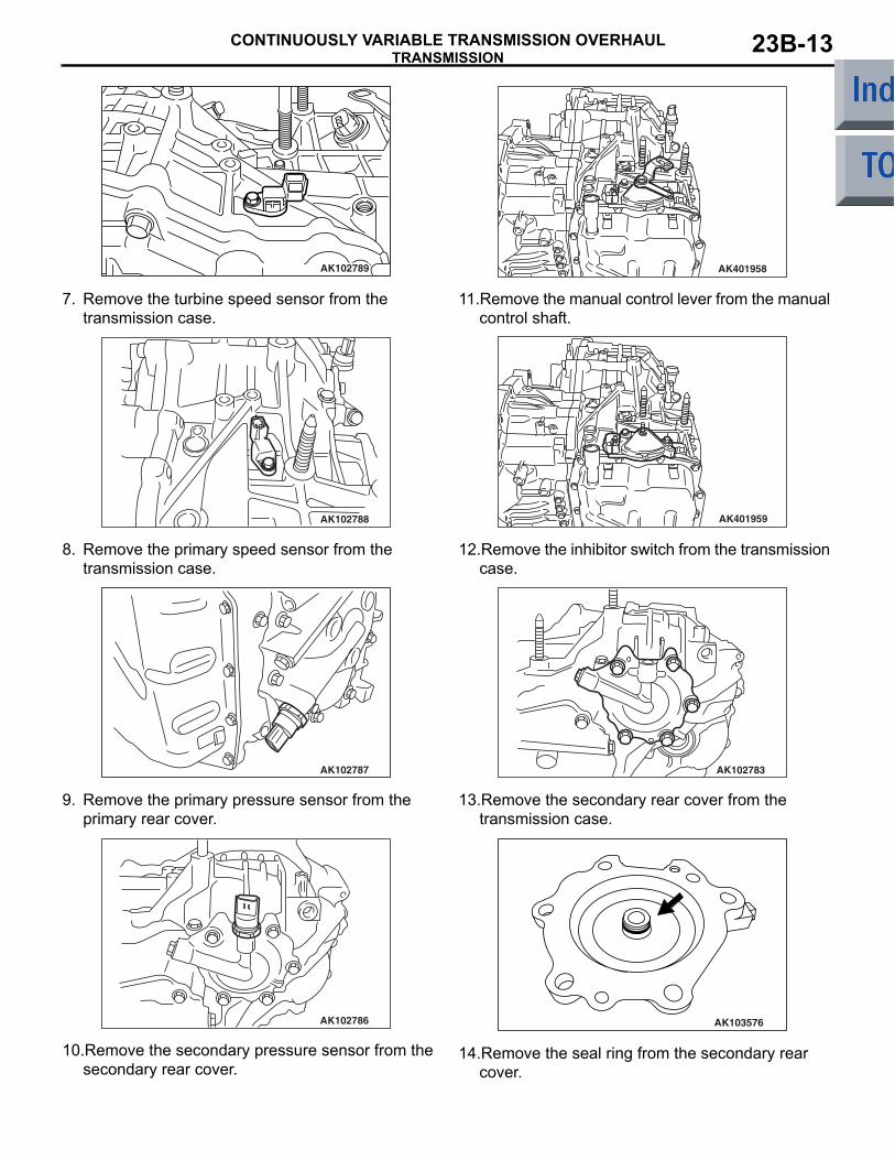
7. Remove the turbine speed sensor from the transmission case.
AK102788
8. Remove the primary speed sensor from the transmission case.
AK102787
9. Remove the primary pressure sensor from the primary rear cover.
AK102786
10.Remove the secondary pressure sensor from the secondary rear cover.
AK401958
11.Remove the manual control lever from the manual control shaft.
AK401959
12.Remove the inhibitor switch from the transmission case.
AK102783
13.Remove the secondary rear cover from the transmission case.
AK103576
14.Remove the seal ring from the secondary rear cover.
TRANSMISSIONCONTINUOUSLY VARIABLE TRANSMISSION OVERHAUL23B-14
AK102779
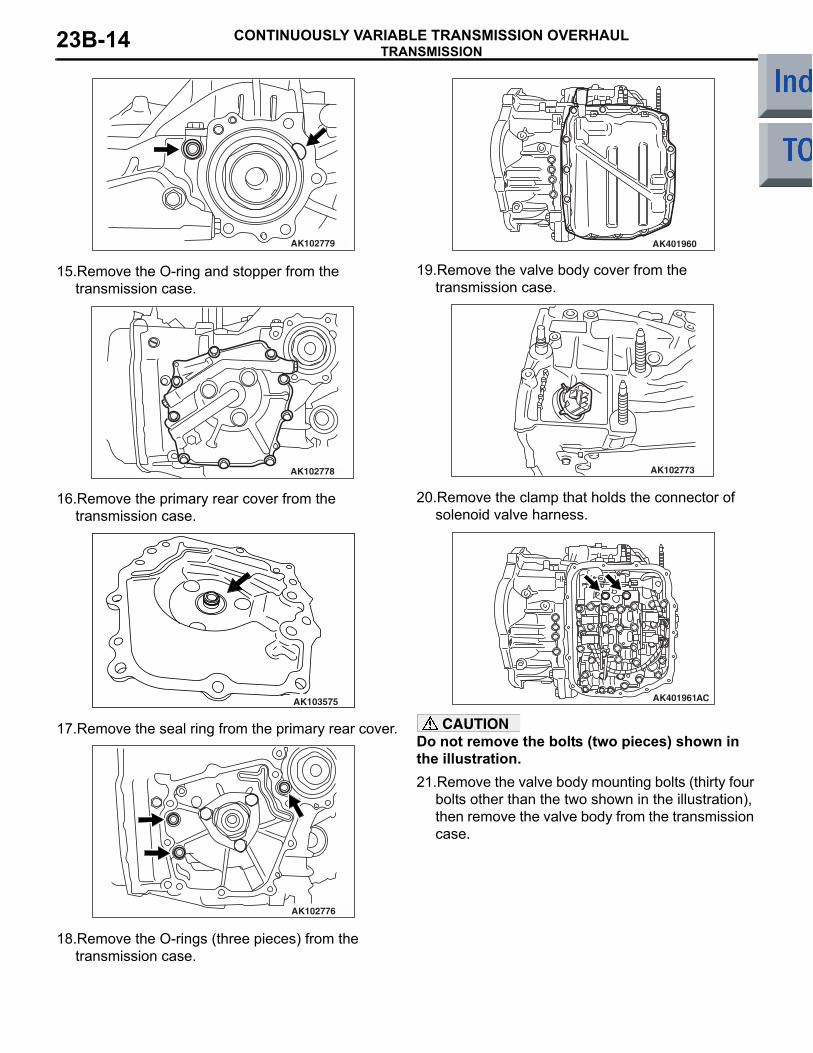
15.Remove the O-ring and stopper from the transmission case.
AK102778
16.Remove the primary rear cover from the transmission case.
AK103575
17.Remove the seal ring from the primary rear cover.
AK102776
18.Remove the O-rings (three pieces) from the transmission case.
AK401960
19.Remove the valve body cover from the transmission case.
AK102773
20.Remove the clamp that holds the connector of solenoid valve harness.
AK401961AC
CAUTIONDo not remove the bolts (two pieces) shown in the illustration.21.Remove the valve body mounting bolts (thirty four
bolts other than the two shown in the illustration), then remove the valve body from the transmission case.
TRANSMISSIONCONTINUOUSLY VARIABLE TRANSMISSION OVERHAUL 23B-15
AK102823
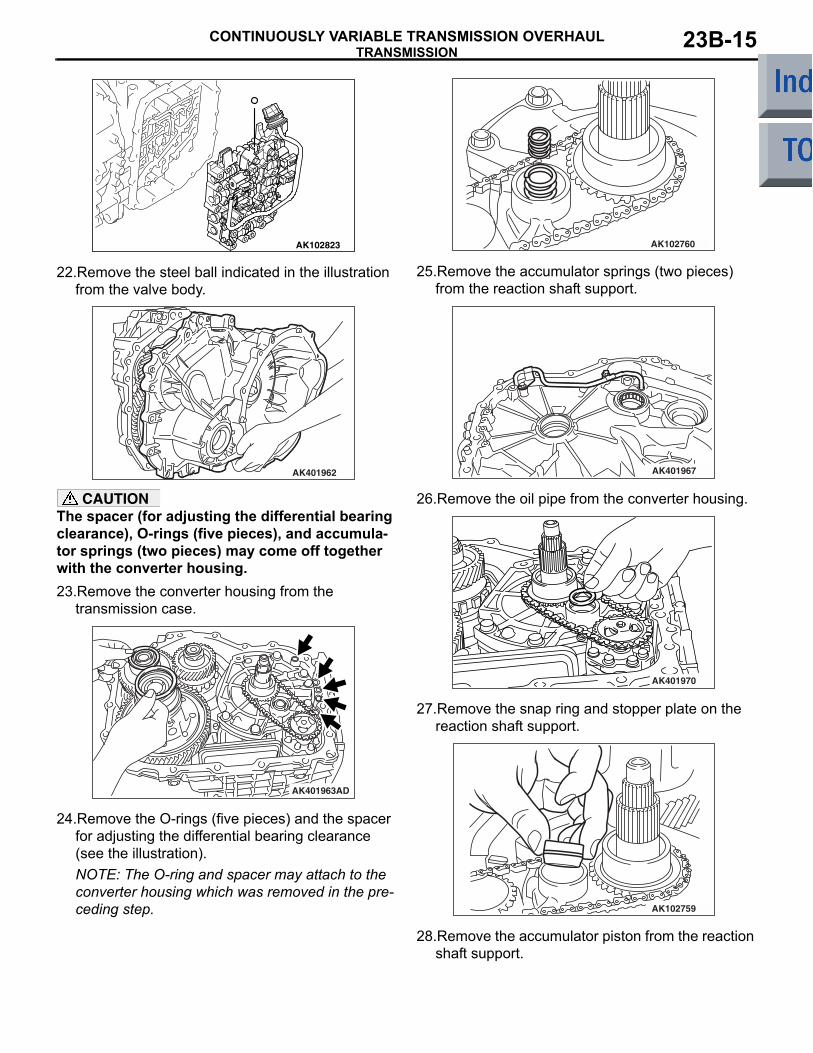
22.Remove the steel ball indicated in the illustration from the valve body.
AK401962
CAUTIONThe spacer (for adjusting the differential bearing clearance), O-rings (five pieces), and accumula-tor springs (two pieces) may come off together with the converter housing.23.Remove the converter housing from the
transmission case.
AK401963AD
24.Remove the O-rings (five pieces) and the spacer for adjusting the differential bearing clearance (see the illustration).NOTE: The O-ring and spacer may attach to the converter housing which was removed in the pre-ceding step.
AK102760
25.Remove the accumulator springs (two pieces) from the reaction shaft support.
AK401967
26.Remove the oil pipe from the converter housing.
AK401970
27.Remove the snap ring and stopper plate on the reaction shaft support.
AK102759
28.Remove the accumulator piston from the reaction shaft support.
TRANSMISSIONCONTINUOUSLY VARIABLE TRANSMISSION OVERHAUL23B-16
AK401971
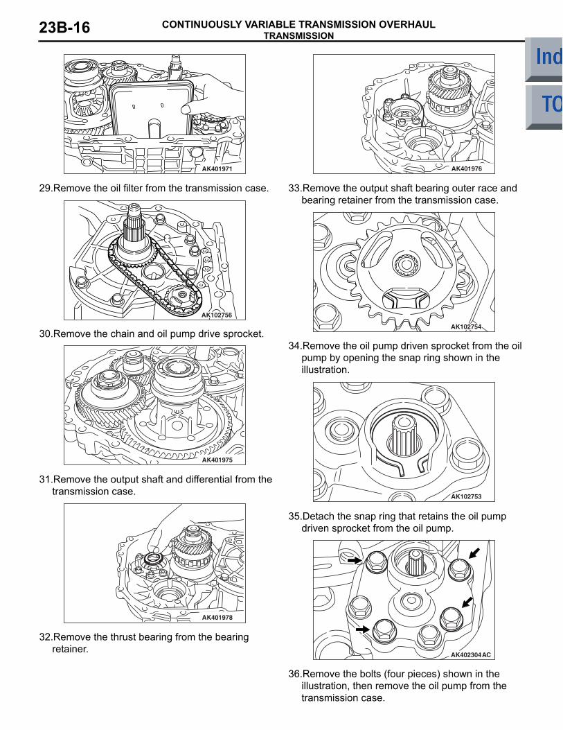
29.Remove the oil filter from the transmission case.
AK102756
30.Remove the chain and oil pump drive sprocket.
AK401975
31.Remove the output shaft and differential from the transmission case.
AK401978
32.Remove the thrust bearing from the bearing retainer.
AK401976
33.Remove the output shaft bearing outer race and bearing retainer from the transmission case.
AK102754
34.Remove the oil pump driven sprocket from the oil pump by opening the snap ring shown in the illustration.
AK102753
35.Detach the snap ring that retains the oil pump driven sprocket from the oil pump.
AK402304AC
36.Remove the bolts (four pieces) shown in the illustration, then remove the oil pump from the transmission case.
TRANSMISSIONCONTINUOUSLY VARIABLE TRANSMISSION OVERHAUL 23B-17
AK102750
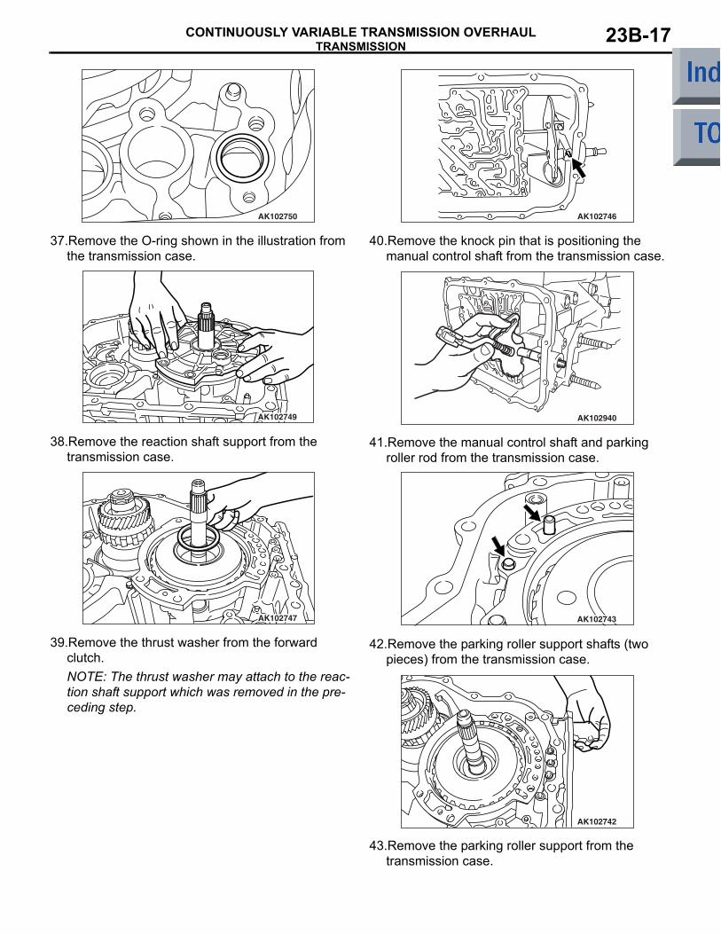
37.Remove the O-ring shown in the illustration from the transmission case.
AK102749
38.Remove the reaction shaft support from the transmission case.
AK102747
39.Remove the thrust washer from the forward clutch.NOTE: The thrust washer may attach to the reac-tion shaft support which was removed in the pre-ceding step.
AK102746
40.Remove the knock pin that is positioning the manual control shaft from the transmission case.
AK102940
41.Remove the manual control shaft and parking roller rod from the transmission case.
AK102743
42.Remove the parking roller support shafts (two pieces) from the transmission case.
AK102742
43.Remove the parking roller support from the transmission case.
TRANSMISSIONCONTINUOUSLY VARIABLE TRANSMISSION OVERHAUL23B-18
AK102741
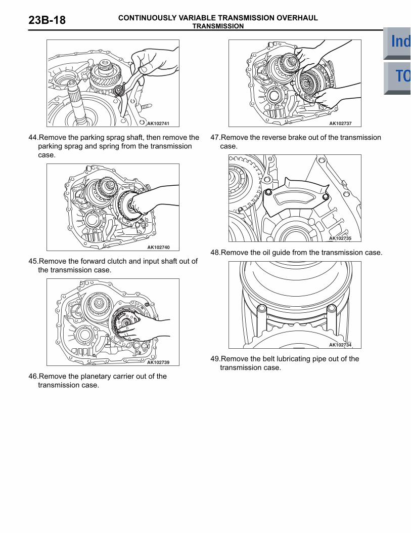
44.Remove the parking sprag shaft, then remove the parking sprag and spring from the transmission case.
AK102740
45.Remove the forward clutch and input shaft out of the transmission case.
AK102739
46.Remove the planetary carrier out of the transmission case.
AK102737
47.Remove the reverse brake out of the transmission case.
AK102735
48.Remove the oil guide from the transmission case.
AK102734
49.Remove the belt lubricating pipe out of the transmission case.
TRANSMISSIONCONTINUOUSLY VARIABLE TRANSMISSION OVERHAUL 23B-19
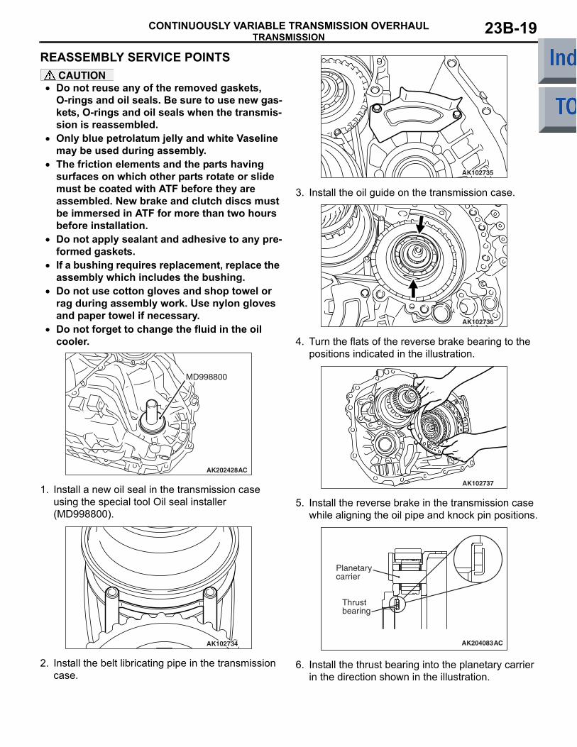
REASSEMBLY SERVICE POINTSCAUTION
• Do not reuse any of the removed gaskets, O-rings and oil seals. Be sure to use new gas-kets, O-rings and oil seals when the transmis-sion is reassembled.
• Only blue petrolatum jelly and white Vaseline may be used during assembly.
• The friction elements and the parts having surfaces on which other parts rotate or slide must be coated with ATF before they are assembled. New brake and clutch discs must be immersed in ATF for more than two hours before installation.
• Do not apply sealant and adhesive to any pre-formed gaskets.
• If a bushing requires replacement, replace the assembly which includes the bushing.
• Do not use cotton gloves and shop towel or rag during assembly work. Use nylon gloves and paper towel if necessary.
•
AK202428
MD998800
AC
Do not forget to change the fluid in the oil cooler.
1. Install a new oil seal in the transmission case using the special tool Oil seal installer (MD998800).
AK102734
2. Install the belt libricating pipe in the transmission case.
AK102735
3. Install the oil guide on the transmission case.
AK102736
4. Turn the flats of the reverse brake bearing to the positions indicated in the illustration.
AK102737
5. Install the reverse brake in the transmission case while aligning the oil pipe and knock pin positions.
AK204083AC
Thrust bearing
Planetary carrier
6. Install the thrust bearing into the planetary carrier in the direction shown in the illustration.
TRANSMISSIONCONTINUOUSLY VARIABLE TRANSMISSION OVERHAUL23B-20
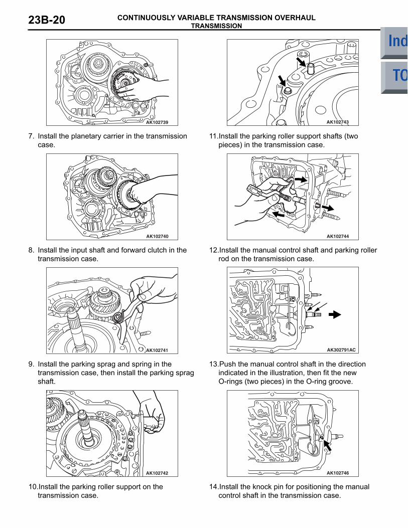
AK102739
7. Install the planetary carrier in the transmission case.
AK102740
8. Install the input shaft and forward clutch in the transmission case.
AK102741
9. Install the parking sprag and spring in the transmission case, then install the parking sprag shaft.
AK102742
10.Install the parking roller support on the transmission case.
AK102743
11.Install the parking roller support shafts (two pieces) in the transmission case.
AK102744
12.Install the manual control shaft and parking roller rod on the transmission case.
AK302791AC
13.Push the manual control shaft in the direction indicated in the illustration, then fit the new O-rings (two pieces) in the O-ring groove.
AK102746
14.Install the knock pin for positioning the manual control shaft in the transmission case.
TRANSMISSIONCONTINUOUSLY VARIABLE TRANSMISSION OVERHAUL 23B-21
AK102841AC
A
B
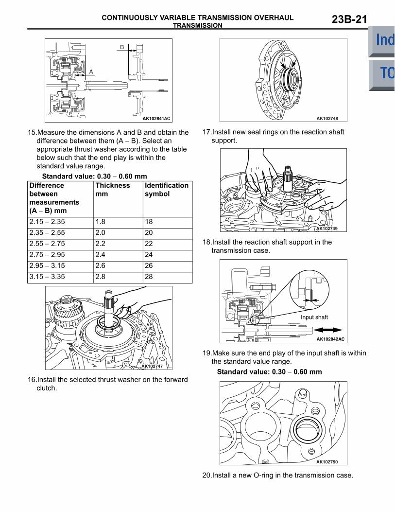
15.Measure the dimensions A and B and obtain the difference between them (A − B). Select an appropriate thrust washer according to the table below such that the end play is within the standard value range.
Standard value: 0.30 − 0.60 mmDifference between measurements (A − B) mm
Thickness mm
Identification symbol
2.15 − 2.35 1.8 182.35 − 2.55 2.0 202.55 − 2.75 2.2 222.75 − 2.95 2.4 242.95 − 3.15 2.6 263.15 − 3.35 2.8 28
AK102747
16.Install the selected thrust washer on the forward clutch.
AK102748
17.Install new seal rings on the reaction shaft support.
AK102749
18.Install the reaction shaft support in the transmission case.
AK102842
Input shaft
AC
19.Make sure the end play of the input shaft is within the standard value range.
Standard value: 0.30 − 0.60 mm
AK102750
20.Install a new O-ring in the transmission case.
TRANSMISSIONCONTINUOUSLY VARIABLE TRANSMISSION OVERHAUL23B-22
AK402304AC
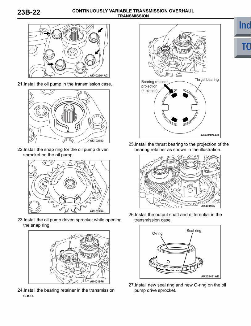
21.Install the oil pump in the transmission case.
AK102753
22.Install the snap ring for the oil pump driven sprocket on the oil pump.
AK102754
23.Install the oil pump driven sprocket while opening the snap ring.
AK401976
24.Install the bearing retainer in the transmission case.
AK402424AD
Thrust bearingBearing retainerprojection(4 places)
25.Install the thrust bearing to the projection of the bearing retainer as shown in the illustration.
AK401975
26.Install the output shaft and differential in the transmission case.
AK202481
Seal ringO-ring
AE
27.Install new seal ring and new O-ring on the oil pump drive sprocket.
TRANSMISSIONCONTINUOUSLY VARIABLE TRANSMISSION OVERHAUL 23B-23
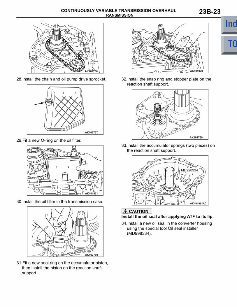
AK102756
28.Install the chain and oil pump drive sprocket.
AK102757
29.Fit a new O-ring on the oil filter.
AK401971
30.Install the oil filter in the transmission case.
AK102759
31.Fit a new seal ring on the accumulator piston, then install the piston on the reaction shaft support.
AK401970
32.Install the snap ring and stopper plate on the reaction shaft support.
AK102760
33.Install the accumulator springs (two pieces) on the reaction shaft support.
AK401991
MD998334
AC
CAUTIONInstall the oil seal after applying ATF to its lip. 34.Install a new oil seal in the converter housing
using the special tool Oil seal installer (MD998334).
TRANSMISSIONCONTINUOUSLY VARIABLE TRANSMISSION OVERHAUL23B-24
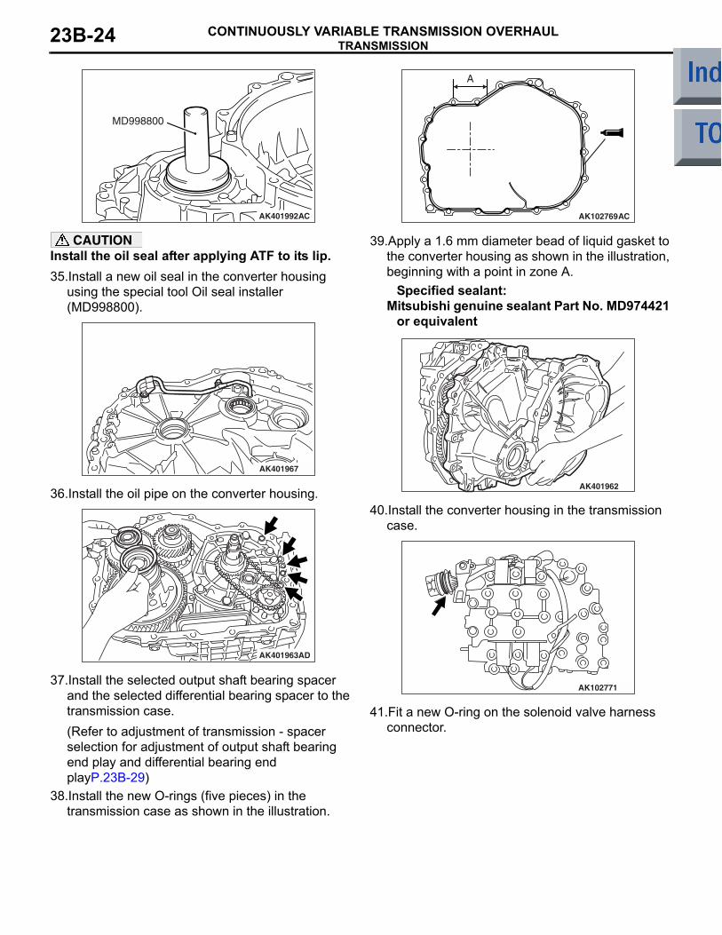
AK401992
MD998800
AC
CAUTIONInstall the oil seal after applying ATF to its lip. 35.Install a new oil seal in the converter housing
using the special tool Oil seal installer (MD998800).
AK401967
36.Install the oil pipe on the converter housing.
AK401963AD
37.Install the selected output shaft bearing spacer and the selected differential bearing spacer to the transmission case.(Refer to adjustment of transmission - spacer selection for adjustment of output shaft bearing end play and differential bearing end playP.23B-29)
38.Install the new O-rings (five pieces) in the transmission case as shown in the illustration.
AK102769
A
AC
39.Apply a 1.6 mm diameter bead of liquid gasket to the converter housing as shown in the illustration, beginning with a point in zone A.
Specified sealant:Mitsubishi genuine sealant Part No. MD974421
or equivalent
AK401962
40.Install the converter housing in the transmission case.
AK102771
41.Fit a new O-ring on the solenoid valve harness connector.
TRANSMISSIONCONTINUOUSLY VARIABLE TRANSMISSION OVERHAUL 23B-25
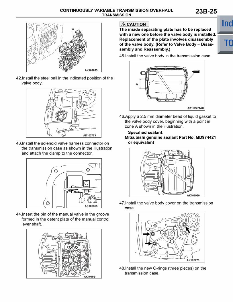
AK102823
42.Install the steel ball in the indicated position of the valve body.
AK102773
43.Install the solenoid valve harness connector on the transmission case as shown in the illustration and attach the clamp to the connector.
AK103665
44.Insert the pin of the manual valve in the groove formed in the detent plate of the manual control lever shaft.
AK401961
CAUTIONThe inside separating plate has to be replaced with a new one before the valve body is installed. Replacement of the plate involves disassembly of the valve body. (Refer to Valve Body − Disas-sembly and Reassembly.)45.Install the valve body in the transmission case.
AK102774
A
AC
46.Apply a 2.5 mm diameter bead of liquid gasket to the valve body cover, beginning with a point in zone A shown in the illustration.
Specified sealant:Mitsubishi genuine sealant Part No. MD974421
or equivalent
AK401960
47.Install the valve body cover on the transmission case.
AK102776
48.Install the new O-rings (three pieces) on the transmission case.
TRANSMISSIONCONTINUOUSLY VARIABLE TRANSMISSION OVERHAUL23B-26
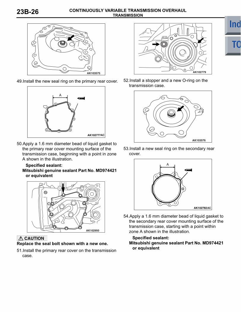
AK103575
49.Install the new seal ring on the primary rear cover.
AK102777AC
A
50.Apply a 1.6 mm diameter bead of liquid gasket to the primary rear cover mounting surface of the transmission case, beginning with a point in zone A shown in the illustration.
Specified sealant:Mitsubishi genuine sealant Part No. MD974421
or equivalent
AK102950
CAUTIONReplace the seal bolt shown with a new one.51.Install the primary rear cover on the transmission
case.
AK102779
52.Install a stopper and a new O-ring on the transmission case.
AK103576
53.Install a new seal ring on the secondary rear cover.
AK102782AC
A
54.Apply a 1.6 mm diameter bead of liquid gasket to the secondary rear cover mounting surface of the transmission case, starting with a point within zone A shown in the illustration.
Specified sealant:Mitsubishi genuine sealant Part No. MD974421
or equivalent
TRANSMISSIONCONTINUOUSLY VARIABLE TRANSMISSION OVERHAUL 23B-27
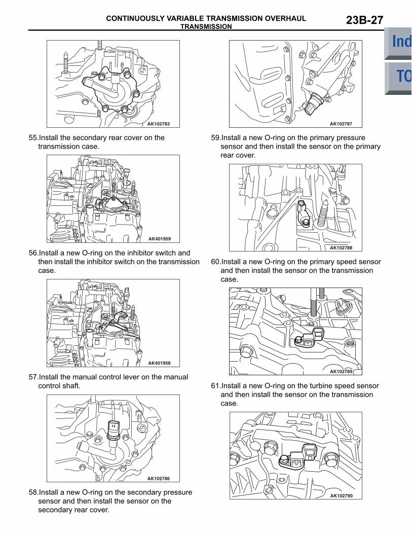
AK102783
55.Install the secondary rear cover on the transmission case.
AK401959
56.Install a new O-ring on the inhibitor switch and then install the inhibitor switch on the transmission case.
AK401958
57.Install the manual control lever on the manual control shaft.
AK102786
58.Install a new O-ring on the secondary pressure sensor and then install the sensor on the secondary rear cover.
AK102787
59.Install a new O-ring on the primary pressure sensor and then install the sensor on the primary rear cover.
AK102788
60.Install a new O-ring on the primary speed sensor and then install the sensor on the transmission case.
AK102789
61.Install a new O-ring on the turbine speed sensor and then install the sensor on the transmission case.
AK102790
TRANSMISSIONCONTINUOUSLY VARIABLE TRANSMISSION OVERHAUL23B-28
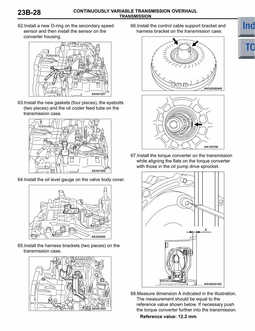
62.Install a new O-ring on the secondary speed sensor and then install the sensor on the converter housing.
AK401957
63.Install the new gaskets (four pieces), the eyebolts (two pieces) and the oil cooler feed tube on the transmission case.
AK401956
64.Install the oil level gauge on the valve body cover.
AK402000
65.Install the harness brackets (two pieces) on the transmission case.
AK401955
66.Install the control cable support bracket and harness bracket on the transmission case.
AK503560AB
AK102798
67.Install the torque converter on the transmission while aligning the flats on the torque converter with those in the oil pump drive sprocket.
AK402001AC
A
68.Measure dimension A indicated in the illustration. The measurement should be equal to the reference value shown below. If necessary push the torque converter further into the transmission.
Reference value: 12.2 mm
TRANSMISSIONCONTINUOUSLY VARIABLE TRANSMISSION OVERHAUL 23B-29
ADJUSTMENT OF TRANSMISSIONM1233030400140
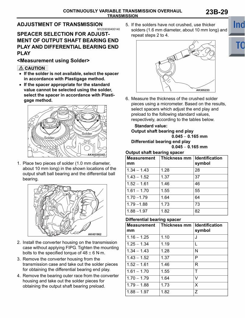
SPEACER SELECTION FOR ADJUST-MENT OF OUTPUT SHAFT BEARING END PLAY AND DIFFERENTIAL BEARING END PLAY<Measurement using Solder>
CAUTION• If the solder is not available, select the spacer
in accordance with Plastigage method.• If the spacer appropriate for the standard
value cannot be selected using the solder, select the spacer in accordance with Plasti-gage method.
AK402202AD
SolderSolder
1. Place two pieces of solder (1.0 mm diameter, about 10 mm long) in the shown locations of the output shaft ball bearing and the differential ball bearing.
AK401962
2. Install the converter housing on the transmission case without applying FIPG. Tighten the mounting bolts to the specified torque of 48 ± 6 N⋅m.
3. Remove the converter housing from the transmission case and take out the solder pieces for obtaining the differential bearing end play.
4. Remove the bearing outer race from the converter housing and take out the solder pieces for obtaining the output shaft bearing preload.
5. If the solders have not crushed, use thicker solders (1.6 mm diameter, about 10 mm long) and repeat steps 2 to 4.
AK305233
6. Measure the thickness of the crushed solder pieces using a micrometer. Based on the results, select spacers which adjust the end play and preload to the following standard values, respectively, according to the tables below.
Standard value:Output shaft bearing end play 0.045 − 0.165 mm Differential bearing end play 0.045 − 0.165 mm
Output shaft bearing spacerMeasurement mm
Thickness mm Identification symbol
1.34 − 1.43 1.28 281.43 − 1.52 1.37 371.52 − 1.61 1.46 461.61 − 1.70 1.55 551.70 −1.79 1.64 641.79 −1.88 1.73 731.88 −1.97 1.82 82
Differential bearing spacerMeasurement mm
Thickness mm Identification symbol
1.16 − 1.25 1.10 J1.25 − 1.34 1.19 L1.34 − 1.43 1.28 N1.43 − 1.52 1.37 P1.52 − 1.61 1.46 R1.61 − 1.70 1.55 T1.70 − 1.79 1.64 V1.79 − 1.88 1.73 X1.88 − 1.97 1.82 Z
TRANSMISSIONCONTINUOUSLY VARIABLE TRANSMISSION OVERHAUL23B-30
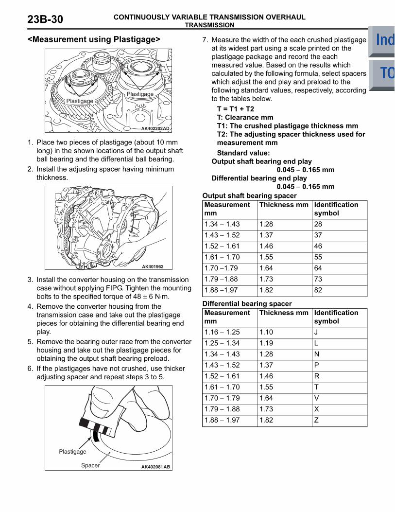
<Measurement using Plastigage>
AK402202AD
PlastigagePlastigage
1. Place two pieces of plastigage (about 10 mm long) in the shown locations of the output shaft ball bearing and the differential ball bearing.
2. Install the adjusting spacer having minimum thickness.
AK401962
3. Install the converter housing on the transmission case without applying FIPG. Tighten the mounting bolts to the specified torque of 48 ± 6 N⋅m.
4. Remove the converter housing from the transmission case and take out the plastigage pieces for obtaining the differential bearing end play.
5. Remove the bearing outer race from the converter housing and take out the plastigage pieces for obtaining the output shaft bearing preload.
6. If the plastigages have not crushed, use thicker adjusting spacer and repeat steps 3 to 5.
AK402081
Plastigage
Spacer AB
7. Measure the width of the each crushed plastigage at its widest part using a scale printed on the plastigage package and record the each measured value. Based on the results which calculated by the following formula, select spacers which adjust the end play and preload to the following standard values, respectively, according to the tables below.
T = T1 + T2T: Clearance mmT1: The crushed plastigage thickness mmT2: The adjusting spacer thickness used for measurement mmStandard value:
Output shaft bearing end play 0.045 − 0.165 mmDifferential bearing end play 0.045 − 0.165 mm
Output shaft bearing spacerMeasurement mm
Thickness mm Identification symbol
1.34 − 1.43 1.28 281.43 − 1.52 1.37 371.52 − 1.61 1.46 461.61 − 1.70 1.55 551.70 −1.79 1.64 641.79 −1.88 1.73 731.88 −1.97 1.82 82
Differential bearing spacerMeasurement mm
Thickness mm Identification symbol
1.16 − 1.25 1.10 J1.25 − 1.34 1.19 L1.34 − 1.43 1.28 N1.43 − 1.52 1.37 P1.52 − 1.61 1.46 R1.61 − 1.70 1.55 T1.70 − 1.79 1.64 V1.79 − 1.88 1.73 X1.88 − 1.97 1.82 Z
FORWARD CLUTCHCONTINUOUSLY VARIABLE TRANSMISSION OVERHAUL 23B-31
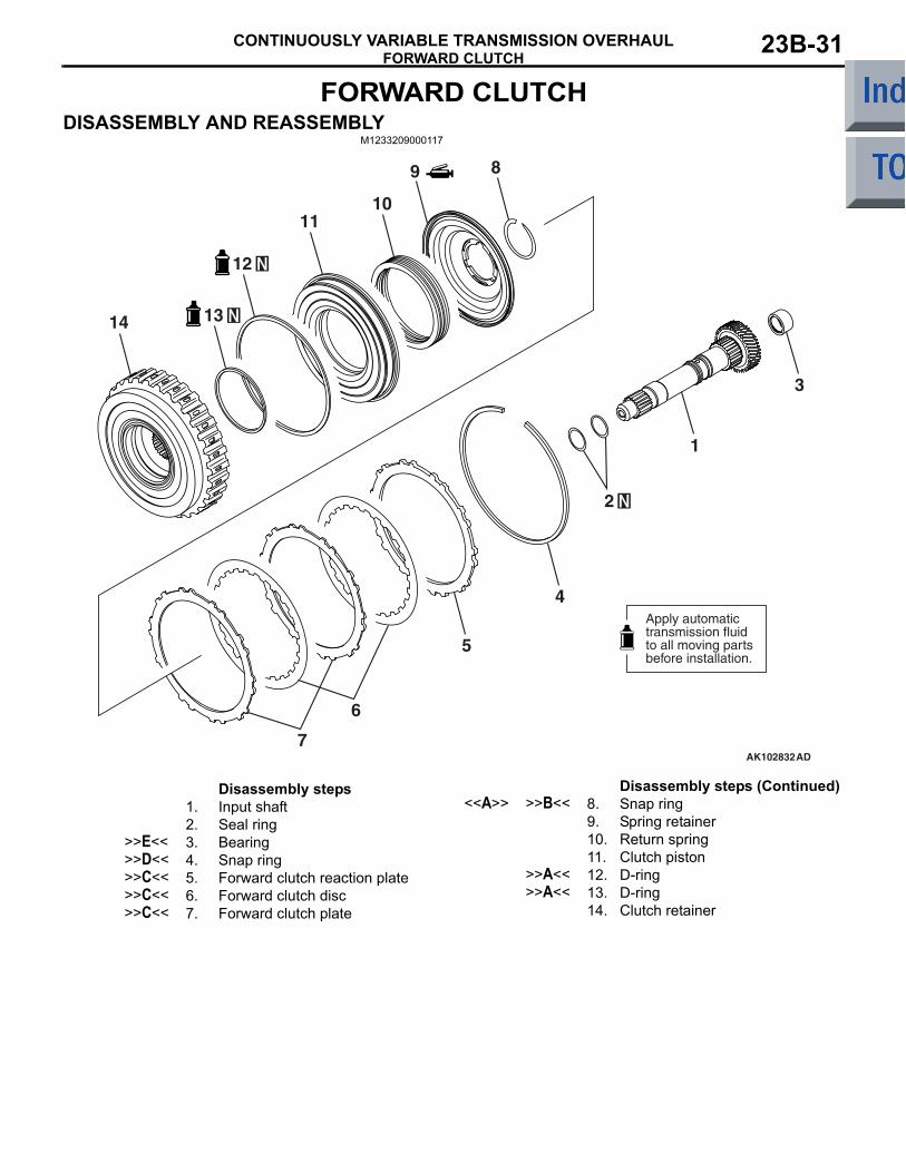
FORWARD CLUTCHDISASSEMBLY AND REASSEMBLY
M1233209000117
AK102832AD
1
2
3
4
5
6
7
89
1011
12
1314
Apply automatictransmission fluidto all moving partsbefore installation.
Disassembly steps 1. Input shaft2. Seal ring
>>E<< 3. Bearing>>D<< 4. Snap ring>>C<< 5. Forward clutch reaction plate>>C<< 6. Forward clutch disc>>C<< 7. Forward clutch plate
<<A>> >>B<< 8. Snap ring9. Spring retainer10. Return spring11. Clutch piston
>>A<< 12. D-ring>>A<< 13. D-ring
14. Clutch retainer
Disassembly steps (Continued)
FORWARD CLUTCHCONTINUOUSLY VARIABLE TRANSMISSION OVERHAUL23B-32
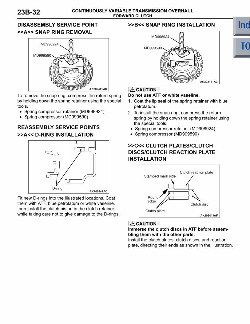
DISASSEMBLY SERVICE POINT<<A>> SNAP RING REMOVAL
AK202441
MD998924
MD999590
AC
To remove the snap ring, compress the return spring by holding down the spring retainer using the special tools.
• Spring compressor retainer (MD998924)• Spring compressor (MD999590)
REASSEMBLY SERVICE POINTS>>A<< D-RING INSTALLATION
AK202442D-ring
AC
Fit new D-rings into the illustrated locations. Coat them with ATF, blue petrolatum or white vaseline, then install the clutch piston in the clutch retainer while taking care not to give damage to the D-rings.
>>B<< SNAP RING INSTALLATION
AK202441
MD998924
MD999590
AC
CAUTIONDo not use ATF or white vaseline.1. Coat the lip seal of the spring retainer with blue
petrolatum.2. To install the snap ring, compress the return
spring by holding down the spring retainer using the special tools.
• Spring compressor retainer (MD998924)• Spring compressor (MD999590)
>>C<< CLUTCH PLATES/CLUTCH DISCS/CLUTCH REACTION PLATE INSTALLATION
AK202443
Round edge
Clutch plate
Stamped mark sideClutch reaction plate
AF
Clutch disc
CAUTIONImmerse the clutch discs in ATF before assem-bling them with the other parts.Install the clutch plates, clutch discs, and reaction plate, directing their ends as shown in the illustration.
FORWARD CLUTCHCONTINUOUSLY VARIABLE TRANSMISSION OVERHAUL 23B-33
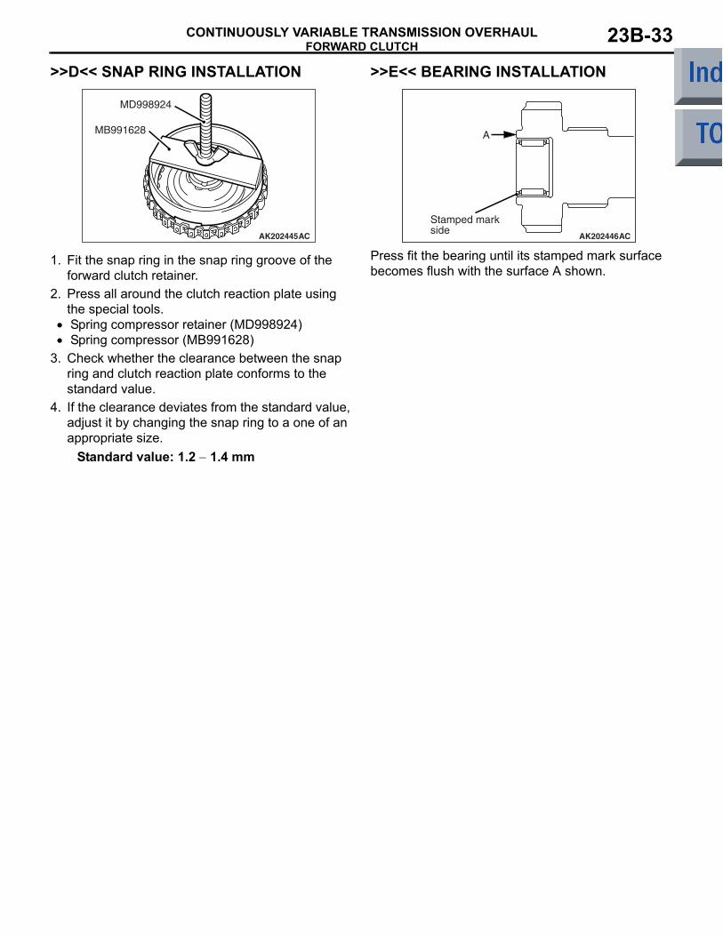
>>D<< SNAP RING INSTALLATION
AK202445
MB991628
MD998924
AC
1. Fit the snap ring in the snap ring groove of the forward clutch retainer.
2. Press all around the clutch reaction plate using the special tools.
• Spring compressor retainer (MD998924)• Spring compressor (MB991628)
3. Check whether the clearance between the snap ring and clutch reaction plate conforms to the standard value.
4. If the clearance deviates from the standard value, adjust it by changing the snap ring to a one of an appropriate size.
Standard value: 1.2 − 1.4 mm
>>E<< BEARING INSTALLATION
AK202446
A
Stamped mark side
AC
Press fit the bearing until its stamped mark surface becomes flush with the surface A shown.
REVERSE BRAKECONTINUOUSLY VARIABLE TRANSMISSION OVERHAUL23B-34
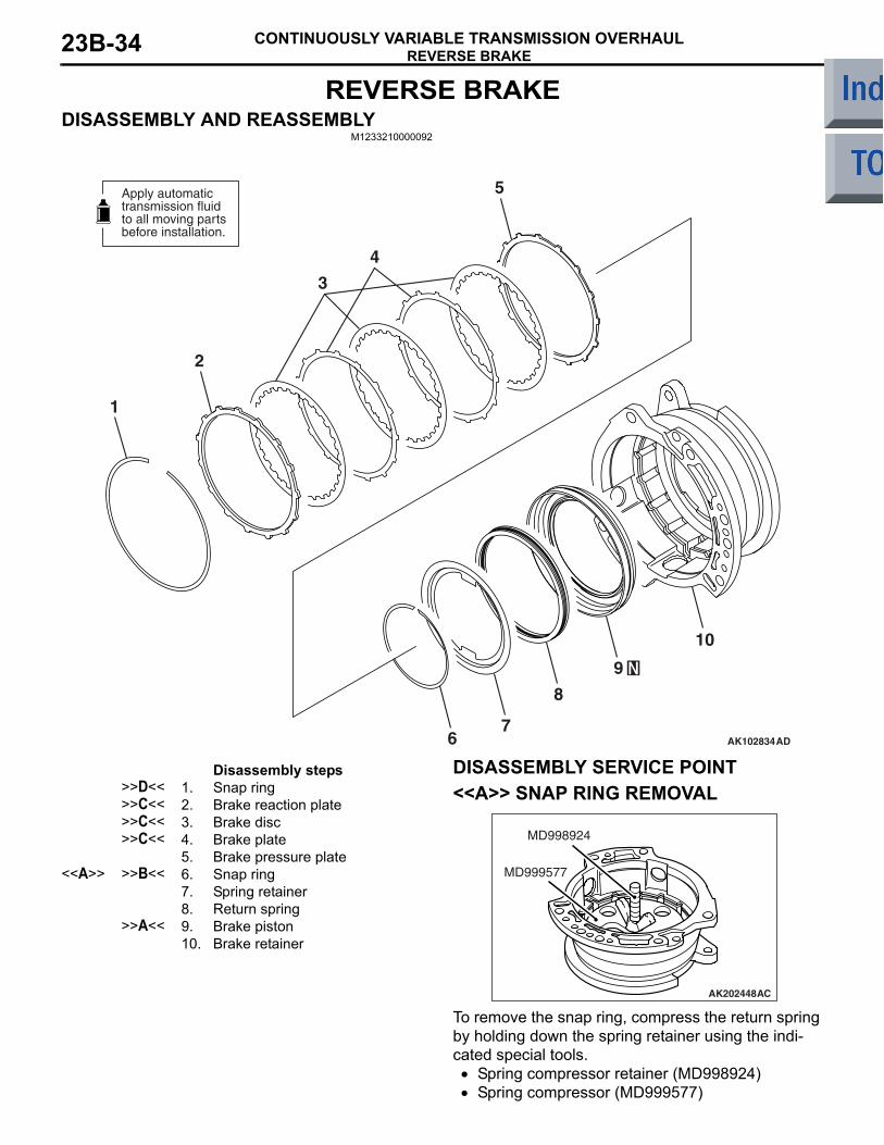
REVERSE BRAKEDISASSEMBLY AND REASSEMBLY
M1233210000092
AK102834AD
1
2
3
4
5
67
8
9
10
Apply automatictransmission fluidto all moving partsbefore installation.
Disassembly steps >>D<< 1. Snap ring>>C<< 2. Brake reaction plate>>C<< 3. Brake disc>>C<< 4. Brake plate
5. Brake pressure plate<<A>> >>B<< 6. Snap ring
7. Spring retainer8. Return spring
>>A<< 9. Brake piston10. Brake retainer
DISASSEMBLY SERVICE POINT<<A>> SNAP RING REMOVAL
AK202448
MD999577
MD998924
AC
To remove the snap ring, compress the return spring by holding down the spring retainer using the indi-cated special tools.
• Spring compressor retainer (MD998924)• Spring compressor (MD999577)
REVERSE BRAKECONTINUOUSLY VARIABLE TRANSMISSION OVERHAUL 23B-35
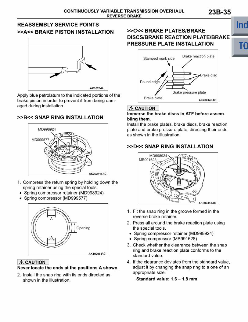
REASSEMBLY SERVICE POINTS>>A<< BRAKE PISTON INSTALLATION
AK102844
Apply blue petrolatum to the indicated portions of the brake piston in order to prevent it from being dam-aged during installation.
>>B<< SNAP RING INSTALLATION
AK202448
MD999577
MD998924
AC
1. Compress the return spring by holding down the spring retainer using the special tools.
• Spring compressor retainer (MD998924)•
AK102951AC
A
A
Opening
Spring compressor (MD999577)
CAUTIONNever locate the ends at the positions A shown.2. Install the snap ring with its ends directed as
shown in the illustration.
>>C<< BRAKE PLATES/BRAKE DISCS/BRAKE REACTION PLATE/BRAKE PRESSURE PLATE INSTALLATION
AK202449
Stamped mark side
Brake plate
Brake disc
AC
Brake reaction plate
Round edge
Brake pressure plate
CAUTIONImmerse the brake discs in ATF before assem-bling them.Install the brake plates, brake discs, brake reaction plate and brake pressure plate, directing their ends as shown in the illustration.
>>D<< SNAP RING INSTALLATION
AK202451
MB991628MD998924
AC
1. Fit the snap ring in the groove formed in the reverse brake retainer.
2. Press all around the brake reaction plate using the special tools.
• Spring compressor retainer (MD998924)• Spring compressor (MB991628)
3. Check whether the clearance between the snap ring and brake reaction plate conforms to the standard value.
4. If the clearance deviates from the standard value, adjust it by changing the snap ring to a one of an appropriate size.
Standard value: 1.6 − 1.8 mm
VALVE BODYCONTINUOUSLY VARIABLE TRANSMISSION OVERHAUL23B-36
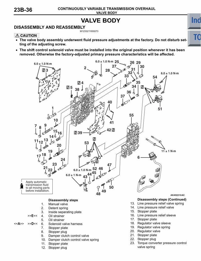
VALVE BODYDISASSEMBLY AND REASSEMBLY
M1233211000073
CAUTION• The valve body assembly underwent fluid pressure adjustments at the factory. Do not disturb set-
ting of the adjusting screw.•
AK402210
6
5049
48
4746
4443
52
53
55
41
40
4239
3736
3435
3029
3132
33 54
51
45
2
1
3
54
71516
17 1819
20
21
2527
6.0 ± 1.0 N·m
6.0 ± 1.0 N·m
6.0 ± 1.0 N·m
6.0 ± 1.0 N·m
11 ± 1 N·m
6.0 ± 1 N·m
26
28
2322
24
8 910
38
1114
1213
AC
Apply automatictransmission fluidto all moving partsbefore installation.
The shift control solenoid valve must be installed into the original position whenever it has been removed. Otherwise the factory-adjusted primary pressure characteristics will be affected.
Disassembly steps 1. Manual valve2. Detent spring3. Inside separating plate
>>E<< 4. Oil strainer5. Oil strainer
<<A>> >>D<< 6. Solenoid valve harness7. Stopper plate8. Stopper plug9. Damper clutch control valve10. Damper clutch control valve spring11. Stopper plate12. Stopper plug
13. Line pressure relief valve spring14. Line pressure relief valve15. Stopper plate16. Line pressure relief sleeve17. Stopper plate18. Regulator valve sleeve19. Regulator valve spring20. Regulator valve21. Stopper plate22. Stopper plug23. Torque converter pressure control
valve spring
Disassembly steps (Continued)
VALVE BODYCONTINUOUSLY VARIABLE TRANSMISSION OVERHAUL 23B-37
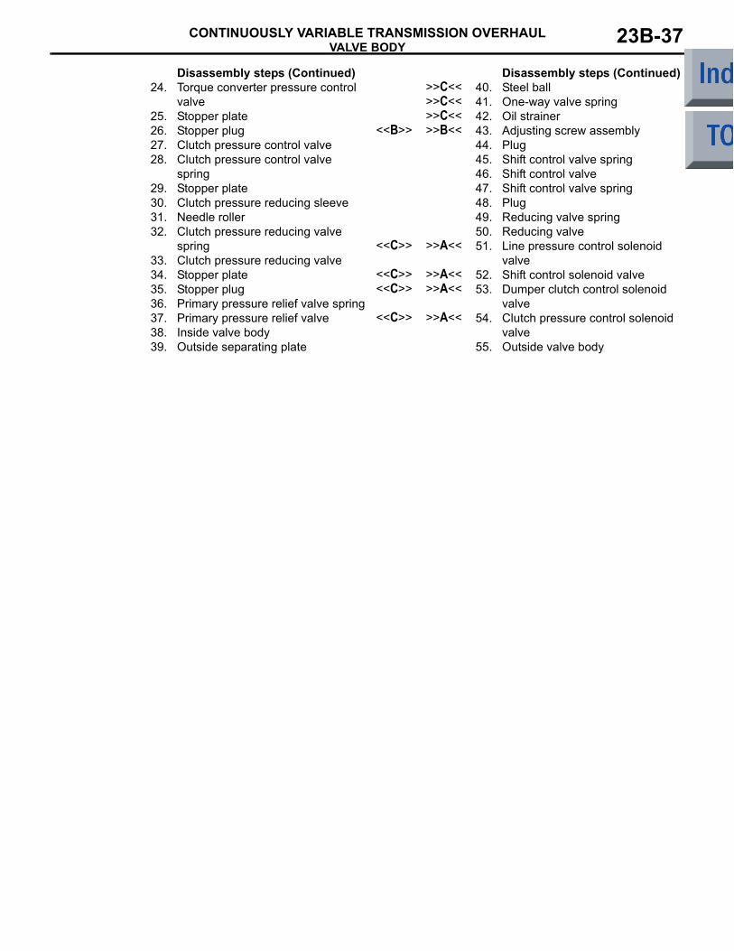
24. Torque converter pressure control valve
25. Stopper plate26. Stopper plug27. Clutch pressure control valve28. Clutch pressure control valve
spring29. Stopper plate30. Clutch pressure reducing sleeve31. Needle roller32. Clutch pressure reducing valve
spring33. Clutch pressure reducing valve34. Stopper plate35. Stopper plug36. Primary pressure relief valve spring37. Primary pressure relief valve38. Inside valve body39. Outside separating plate
Disassembly steps (Continued)>>C<< 40. Steel ball>>C<< 41. One-way valve spring>>C<< 42. Oil strainer
<<B>> >>B<< 43. Adjusting screw assembly44. Plug45. Shift control valve spring46. Shift control valve47. Shift control valve spring48. Plug49. Reducing valve spring50. Reducing valve
<<C>> >>A<< 51. Line pressure control solenoid valve
<<C>> >>A<< 52. Shift control solenoid valve<<C>> >>A<< 53. Dumper clutch control solenoid
valve<<C>> >>A<< 54. Clutch pressure control solenoid
valve55. Outside valve body
Disassembly steps (Continued)
VALVE BODYCONTINUOUSLY VARIABLE TRANSMISSION OVERHAUL23B-38
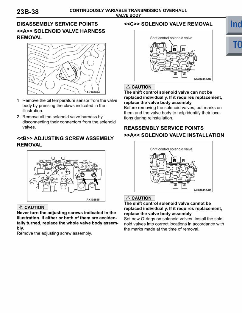
DISASSEMBLY SERVICE POINTS<<A>> SOLENOID VALVE HARNESS REMOVAL
AK102824
1. Remove the oil temperature sensor from the valve body by pressing the claws indicated in the illustration.
2. Remove all the solenoid valve harness by disconnecting their connectors from the solenoid valves.
<<B>> ADJUSTING SCREW ASSEMBLY REMOVAL
AK102825
CAUTIONNever turn the adjusting screws indicated in the illustration. If either or both of them are acciden-tally turned, replace the whole valve body assem-bly.Remove the adjusting screw assembly.
<<C>> SOLENOID VALVE REMOVAL
AK202453
Shift control solenoid valve
AC
CAUTIONThe shift control solenoid valve can not be replaced individually. If it requires replacement, replace the valve body assembly.Before removing the solenoid valves, put marks on them and the valve body to help identify their loca-tions during reinstallation.
REASSEMBLY SERVICE POINTS>>A<< SOLENOID VALVE INSTALLATION
AK202453
Shift control solenoid valve
AC
CAUTIONThe shift control solenoid valve cannot be replaced individually. If it requires replacement, replace the valve body assembly.Set new O-rings on solenoid valves. Install the sole-noid valves into correct locations in accordance with the marks made at the time of removal.
VALVE BODYCONTINUOUSLY VARIABLE TRANSMISSION OVERHAUL 23B-39
>>B<< ADJUSTING SCREW ASSEMBLY INSTALLATION
AK102825
CAUTIONNever turn the adjusting screws indicated in the illustration. If either or both of them are acciden-tally turned, replace the whole valve body assem-bly.Install the adjusting screw assembly in portion.
>>C<< OIL STRAINER/ONE-WAY VALVE SPRING/STEEL BALL INSTALLATION
AK202454Oil strainer
One-way valve spring and steel ball
AC
Install the oil strainer, one-way valve springs and steel balls into the indicated locations.
>>D<< SOLENOID VALVE HARNESS INSTALLATION
AK102824
1. Fit the claws of the oil temperature sensor indicated in the illustration snugly in the valve body.
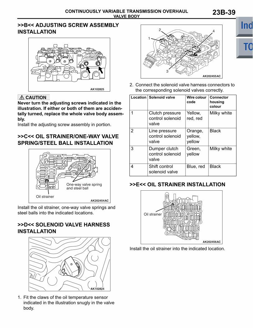
AK202455
1
2
3
4
AC
2. Connect the solenoid valve harness connectors to the corresponding solenoid valves correctly.
Location Solenoid valve Wire colour code
Connector housing colour
1 Clutch pressure control solenoid valve
Yellow, red, red
Milky white
2 Line pressure control solenoid valve
Orange, yellow, yellow
Black
3 Dumper clutch control solenoid valve
Green, yellow
Milky white
4 Shift control solenoid valve
Blue, red Black
>>E<< OIL STRAINER INSTALLATION
AK202456
Oil strainer
AC
Install the oil strainer into the indicated location.
OUTPUT SHAFTCONTINUOUSLY VARIABLE TRANSMISSION OVERHAUL23B-40
OUTPUT SHAFTDISASSEMBLY AND REASSEMBLY
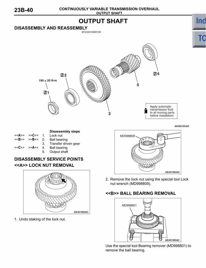
M1233212000139
AK402185AC
3
5
1
190 ± 20 N·m
2 4
Apply automatictransmission fluidto all moving partsbefore installation.
Disassembly steps <<A>> >>C<< 1. Lock nut<<B>> >>B<< 2. Ball bearing
3. Transfer driven gear<<C>> >>A<< 4. Ball bearing
5. Output shaft
DISASSEMBLY SERVICE POINTS<<A>> LOCK NUT REMOVAL
AK401993AC
1. Undo staking of the lock nut.
AK401994
MD998809
AC
2. Remove the lock nut using the special tool Lock nut wrench (MD998809).
<<B>> BALL BEARING REMOVAL
AK401995
MD998801
AC
Use the special tool Bearing remover (MD998801) to remove the ball bearing.
OUTPUT SHAFTCONTINUOUSLY VARIABLE TRANSMISSION OVERHAUL 23B-41
<<C>> BALL BEARING REMOVAL
AK401996
MD998801
AB
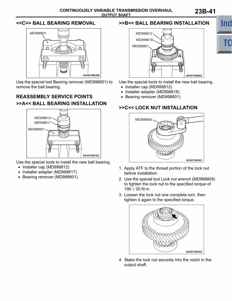
Use the special tool Bearing remover (MD998801) to remove the ball bearing.
REASSEMBLY SERVICE POINTS>>A<< BALL BEARING INSTALLATION
AK401997
MD998812
MD998801
MD998817
AC
Use the special tools to install the new ball bearing.• Installer cap (MD998812)• Installer adapter (MD998817)• Bearing remover (MD998801)
>>B<< BALL BEARING INSTALLATION
AK401998
MD998812
MD998818
MD998801
AC
Use the special tools to install the new ball bearing.• Installer cap (MD998812)• Installer adapter (MD998818)• Bearing remover (MD998801)
>>C<< LOCK NUT INSTALLATION
AK401994
MD998809
AC
1. Apply ATF to the thread portion of the lock nut before installation.
2. Use the special tool Lock nut wrench (MD998809) to tighten the lock nut to the specified torque of 190 ± 20 N⋅m.
3. Loosen the lock nut one complete turn, then tighten it again to the specified torque.
AK401993AC
4. Stake the lock nut securely into the notch in the output shaft.
DIFFERENTIALCONTINUOUSLY VARIABLE TRANSMISSION OVERHAUL23B-42
DIFFERENTIALDISASSEMBLY AND REASSEMBLY
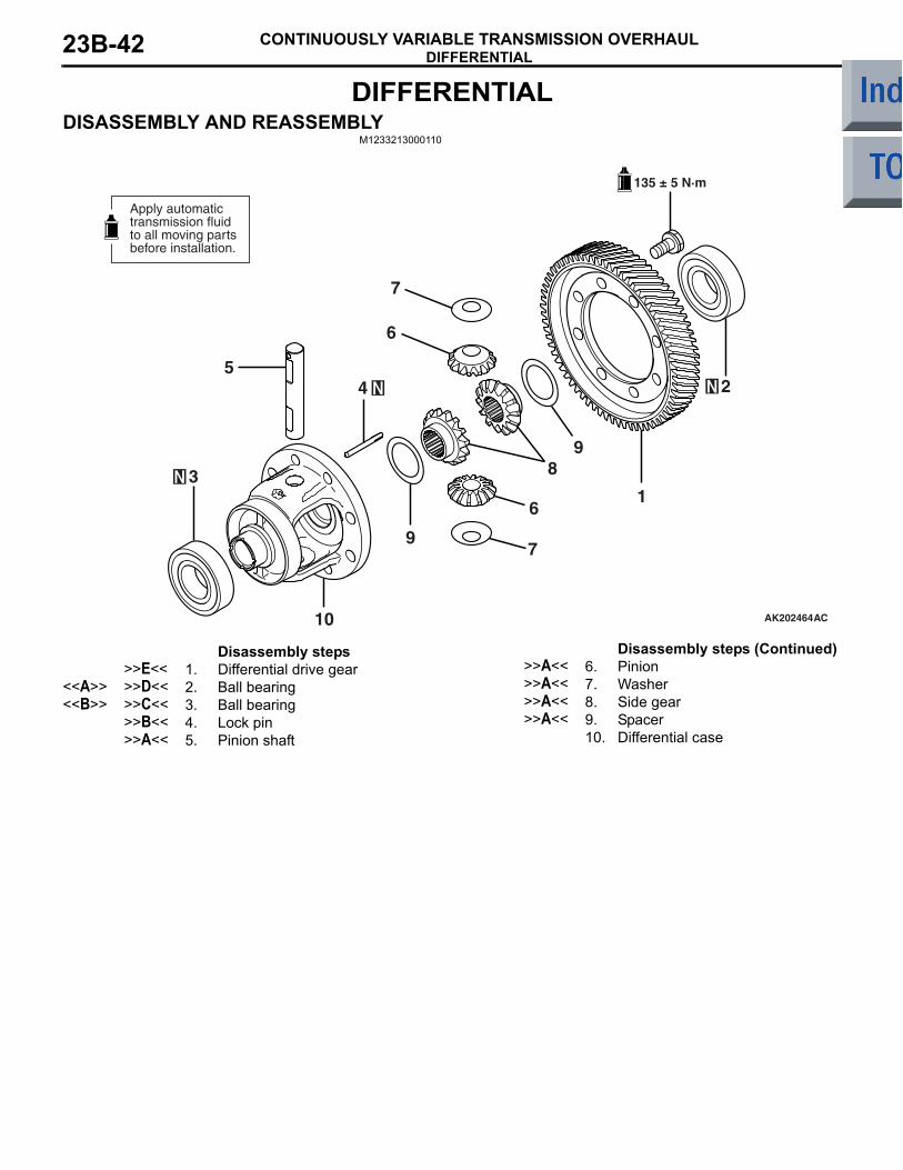
M1233213000110
AK202464
135 ± 5 N·m
1
2
6
5
3
4
7
10
6
8
9
9
7
AC
Apply automatictransmission fluidto all moving partsbefore installation.
Disassembly steps >>E<< 1. Differential drive gear
<<A>> >>D<< 2. Ball bearing<<B>> >>C<< 3. Ball bearing
>>B<< 4. Lock pin>>A<< 5. Pinion shaft
>>A<< 6. Pinion>>A<< 7. Washer>>A<< 8. Side gear>>A<< 9. Spacer
10. Differential case
Disassembly steps (Continued)
DIFFERENTIALCONTINUOUSLY VARIABLE TRANSMISSION OVERHAUL 23B-43
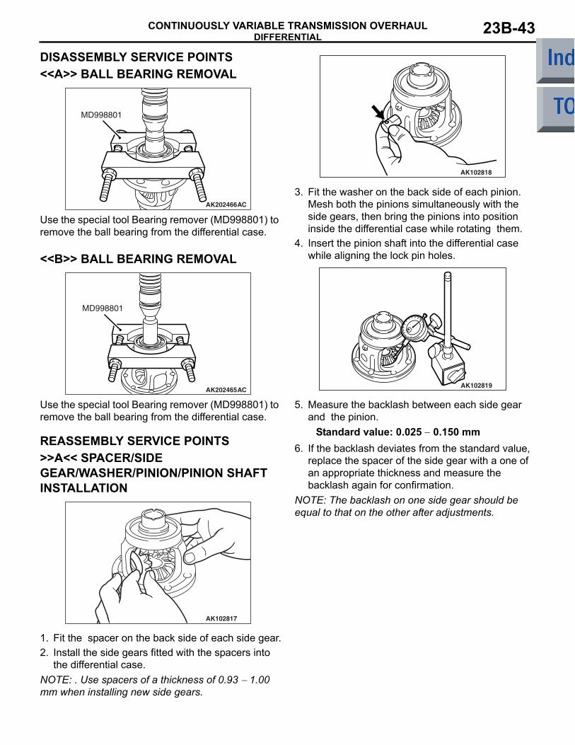
DISASSEMBLY SERVICE POINTS<<A>> BALL BEARING REMOVAL
AK202466
MD998801
AC
Use the special tool Bearing remover (MD998801) to remove the ball bearing from the differential case.
<<B>> BALL BEARING REMOVAL
AK202465
MD998801
AC
Use the special tool Bearing remover (MD998801) to remove the ball bearing from the differential case.
REASSEMBLY SERVICE POINTS>>A<< SPACER/SIDE GEAR/WASHER/PINION/PINION SHAFT INSTALLATION
AK102817
1. Fit the spacer on the back side of each side gear.2. Install the side gears fitted with the spacers into
the differential case.NOTE: . Use spacers of a thickness of 0.93 − 1.00 mm when installing new side gears.
AK102818
3. Fit the washer on the back side of each pinion. Mesh both the pinions simultaneously with the side gears, then bring the pinions into position inside the differential case while rotating them.
4. Insert the pinion shaft into the differential case while aligning the lock pin holes.
AK102819
5. Measure the backlash between each side gear and the pinion.
Standard value: 0.025 − 0.150 mm6. If the backlash deviates from the standard value,
replace the spacer of the side gear with a one of an appropriate thickness and measure the backlash again for confirmation.
NOTE: The backlash on one side gear should be equal to that on the other after adjustments.
DIFFERENTIALCONTINUOUSLY VARIABLE TRANSMISSION OVERHAUL23B-44
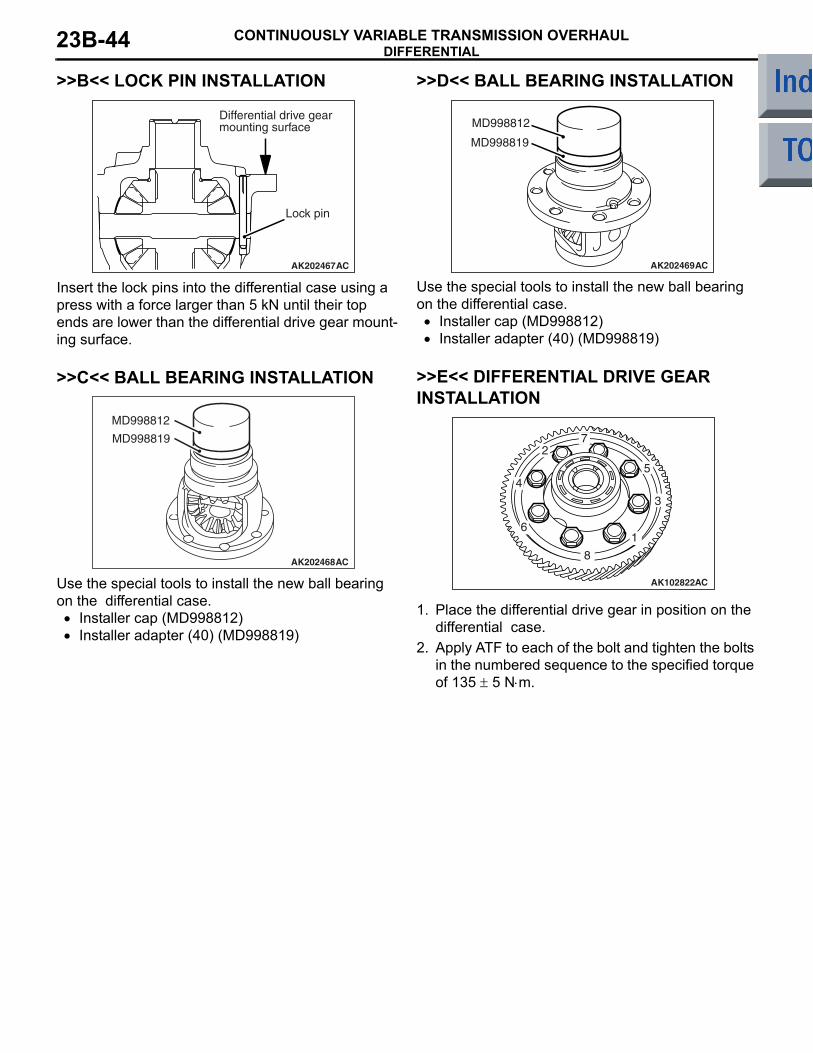
>>B<< LOCK PIN INSTALLATION
AK202467
Differential drive gear mounting surface
Lock pin
AC
Insert the lock pins into the differential case using a press with a force larger than 5 kN until their top ends are lower than the differential drive gear mount-ing surface.
>>C<< BALL BEARING INSTALLATION
AK202468
MD998812
MD998819
AC
Use the special tools to install the new ball bearing on the differential case.
• Installer cap (MD998812)• Installer adapter (40) (MD998819)
>>D<< BALL BEARING INSTALLATION
AK202469
MD998812
MD998819
AC
Use the special tools to install the new ball bearing on the differential case.
• Installer cap (MD998812)• Installer adapter (40) (MD998819)
>>E<< DIFFERENTIAL DRIVE GEAR INSTALLATION
AK102822AC
8
1
3
5
72
4
6
1. Place the differential drive gear in position on the differential case.
2. Apply ATF to each of the bolt and tighten the bolts in the numbered sequence to the specified torque of 135 ± 5 N⋅m.