Embed Size (px)
Citation preview
TORQUEFLITE TRANSMISSION — 1
Group 21
TRANSMISSION (TORQUE CONVERTER)
TORQUEFLITE TRANSMISSION
CONTENTS Paragraph Page
Accumulator Piston Instal lat ion 105 59
Removal - - - 44 39
Inspection 83 51
Back-Up L i g h t Switch 12 26
Band Levers Instal la t ion 94 55
Removal 41 38
Band Adjustments .............................................................. 9 22 Kickdown Low-Reverse
Inspection 79 50
Ins ta l la t ion—Kickdown 92 55
Low-Reverse 93 55
Removal—Kickdown 40 37
Low-Reverse 39 37
Clutch — Fron t — Assembly 78 49
Checking End Clearance—After Assembly 103 58
Before Disassembly............ 31 34
Disassembly .. -. .- 76 48
Clutch Overrunning — Disassembly 64 . 45
Clutch — Rear — Piston Retainer
Assembly 69 47
Disassembly ' 65 46
Eccentric Dowel Char t 70
2— TORQUEFLITE TRANSMISSION
Paragraph Page
Extension Housing - - 23 30
Inspection - - 51 41
Instal la t ion . 101 57
Removal - 33 35
Extension Housing — Bushing
Insta l la t ion 53 41
Removal - - — - 52 41
Gearshift Control Cable - - 14 26 Removal Insta l la t ion
Gearshift Control Cable Adjus tment 7 21 Insta l la t ion Removal
Gearshift Control U n i t . - 12 26 Instal la t ion Removal Back-Up L i g h t Switch Replacement
Governor . - — - 24 31
Assembly -- - 56 42
Disassembly - - 54 41
Instal la t ion - - - 100 57
Removal ( U n i t out of Vehicle) ._ _ - 34 36
Servicing in Vehicle - --- 24 31
Housing Face and Bore Runout (Torque Converter) 116 68 Bore Runout Face Runout
Hydraul ic Control System 5 18
Hydraul ic Pressure — Checks and Adjus tment 11 24 Governor Line Lubr ica t ion Thro t t l e Thro t t l e Compensated
Kickdown Piston - - - 21 29 Removal Instal la t ion
Inspection - 82 50
TORQUEFLITE TRANSMISSION — 3
Paragraph Page
Neut ra l Star ter Switch - - 8 22 Removal Instal lat ion
Oil Leaks - - 6 20
Oil Pan Removal - - - - - 19 28 Instal lat ion
Oil Pan and Gasket
Instal la t ion - ----- 107 60
Removal Out of Car . . - 1 - - 29 34
Replacement in Car - - 19 28
Oil Pump -— Fron t
Instal lat ion - 89 53
Oil Seal Replacement . - - 85 52
Removal - - - 45 39
Oil Pump — Rear - 25 32
Instal lat ion 99 56
Removal ----- 34 36
Servicing in Vehicle 25 32
Inspection 55 42
Operating Principles - 3 13
Output Shaft Rear Oil Seal . 22 29 Removal Instal lat ion
Output Shaft Support - - 35 36
Inspection . 57 42
Instal lat ion _ 98 56 Removal
Pa rk ing Brake - 32 35
Instal la t ion - 102 57 Removal
Power Flow i n the Transmission 4 15
Power T r a i n U n i t No. 1—Output Shaft, Kickdown Planet Pinion
Carrier and Intermediate Shaft Assemblies 36 36
Disassembly - 58 42
TORQUEFLITE TRANSMISSION
Paragraph Page
Power T r a i n (Continued)
Instal la t ion 97 56
Reassembly 63 44
Removal 36 36
Inspection - —— 59 43
U n i t No. 2—Sun Gear, Reverse Planet Pinion Carrier,
Overrunning Clutch and Rear Clutch Assembly .... 37 36
Assembly 75 48
Disassembly 64 45
Instal la t ion - 96 55
Removal - - - 37 36
Inspection - - - 66 46
U n i t No. 3 — F ron t Clutch Piston Retainer and
Inpu t Shaft Assemblies 38 37
Disassembly 76 48
Instal lat ion 95 55
Reassembly - - 78 49
Removal - 38 37
Inspection - 77 49 Push Bu t ton Lamp Replacement 13 26
Regulator Valve Assembly 17 28 Removal
. Ins ta l la t ion
Regulator Valve Body
Inspection — Includes Valves 86 52
Instal la t ion - 88 53
Removal 46 39
Service Diagnosis Char t — 9
Service Diagnosis Explanat ion 2 10
Servos
L o w — Reverse — Ins ta l la t ion 91 55
Removal - 42 38
Kickdown — ins ta l la t ion 90 54
Removal 43 39
Shim Thickness Chart
TORQUEFLITE TRANSMISSION — 5
Paragraph Page
Star ter Pang Gear 114 67 Removal Insta l la t ion
Speedometer Pinion and Chart 15 27
Thro t t l e Linkage Adjus tment - - 10 23
Torque Converter — Flushing — 27 33
Torque Converter Control Valve Assembly 18 28 Removal Insta l la t ion
Torque Converter and Housing 113 66 Removal Instal la t ion
Torque Converter H u b Runout — 115 68 Checking Hub Runout Correcting Hub Runout
Torque Converter Reaction Shaft
Inspection - 49 40
Instal la t ion 87 53
Removal - - 47 40
Torque Reference
Transmission - --- - 26 33 Removal
Instal la t ion ....... - - 108 60
Transmission Case Inspection - - 50 40
Extension Housing —- 51 41
Valve Body and Transfer Plate . - 20 28
Assembly — — 111 63
Cleaning and Inspection 110 63
Disassembly , 109 60
Insta l la t ion 106 59
Removal - 30 34
6 — TORQUEFLITE TRANSMISSION
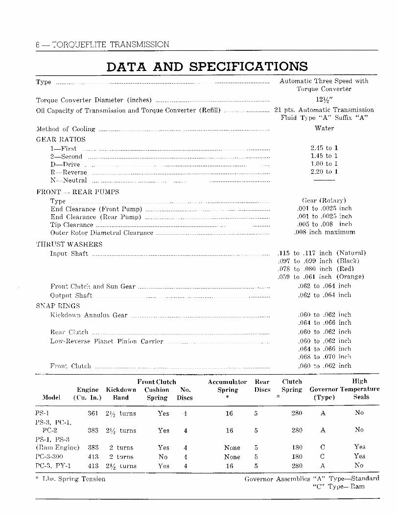
AND SPECIFICATIONS Type - - Automat ic Three Speed w i t h
Torque Converter
Torque Converter Diameter (inches) - 12 1/2 / /
Oil Capacity of Transmission and Torque Converter (Refill) - 21 pts. Automat ic Transmission
Flu id Type a A " Suffix " A "
Method of Cooling - Water
G E A R RATIOS l _ F i r s t 2.45 to 1 2—Second 1.45 to 1 D _ D r i v e 1.00 to 1 R_Reverse 2.20 to 1 N—N e u t r a l
F R O N T — R E A R PUMPS Type Gear (Rotary) End Clearance (Front Pump) .001 to .0025 inch End Clearance (Rear Pump) .001 to .0025 inch T ip Clearance .005 to .008 inch Outer Rotor Diametra l Clearance .008 inch maximum
T H R U S T W A S H E R S Inpu t Shaft . 115 to .117 inch (Natura l )
.097 to .099 inch (Black)
.078 to .080 inch (Red)
.059 to .061 inch (Orange) F ron t Clutch and Sun Gear .062 to .064 inch Output Shaft .062 to .064 Inch
SNAP RINGS Kickdown Annulus Gear _ .060 to .062 inch
.064 to .066 inch Rear Clutch .060 to .062 inch Low-Reverse Planet Pinion Carrier .060 to .062 inch
.064 to .066 Inch
.068 to .070 inch Fron t Clutch .060 to .062 inch
Front Clutch Accumulator Rear Clutch High Engine Kickdown Cushion No. Spring Discs Spring Governor Temperature
Mode! (Cu. In.) Band Spring Discs * (Type) Seals
PS-1 361 214 turns Yes 4 16 5 280 A No
PS-3, PC-1, PC-2 383 214 turns Yes 4 16 5 280 A No
PS-1, PS-3 (Ram Engine) 383 2 turns Yes 4 None 5 180 C Yes
PC-3-300 413 2 turns No 4 None 5 180 C Yes
PC-3, PY-1 413 2% turns Yes 4 16 5 280 A No
Lbs. Spring Tension Governor Assemblies "A" Type—Standard "C" Type—Ram
TORQUEFLITE TRANSMISSION — 7
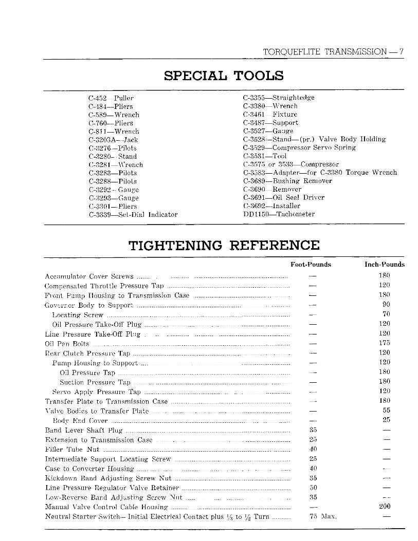
C-452—Puller C-484—Pliers C-589—Wrench C-760—Pliers C-811—Wrench C-3203A—Jack C-3276—Pilots C-3280—Stand C-3281—Wrench 0-3283—Pilots C-3288—Pilots C-3292—Gauge C-3293—Gauge C-3301—Pliers C-3339—Set-Dial Indicator
C-3355—Straightedge C-3380—Wrench C-3461—Fixture C-3487—Support C-3527—Gauge C-3528—Stand— (pr .) Valve Body Hold ing C-3529—Compressor Servo Spring C-3531—Tool C-3575 or 3533—Compressor C-3583—Adapter—for C-3380 Torque Wrench C-3689—Bushing Remover C-3690—Remover C-3691—Oil Seal Dr ive r C-3692—Installer DD1150—Tachometer
TIGHTENING REFERENCE Foot-Pounds Inch-Pounds
Accumulator Cover Screws - — 180 Compensated Thro t t l e Pressure Tap . - — 120 Fron t Pump Housing to Transmission Case ~ — 180 Governor Body to Support — 90
Locat ing Screw - - — 70 Oil Pressure Take-Off Plug — 120
Line Pressure Take-Off Plug _ —- 120 Oil Pan Bolts . _ . - — 175 Rear Clutch Pressure Tap --- — 120
Pump Housing to Support — 120 Oil Pressure Tap . - — 180 Suction Pressure Tap - ---- — 180
Servo Apply Pressure Tap . — 120 Transfer Plate to Transmission Case — 180 Valve Bodies to Transfer Plate — 55
Body End Cover — ' 25 Band Lever Shaft Plug 35 — Extension to Transmission Case 25 — Fi l ler Tube N u t 40 — Intermediate Support Locat ing Screw 25 — Case to Converter Housing 40 — Kickdown Band Ad jus t ing Screw N u t 35 — Line Pressure Regulator Valve Retainer 50 — Low-Reverse Band Ad jus t i ng Screw N u t 35 — Manual Valve Control Cable Housing — 200 Neu t ra l Starter S w i t c h — I n i t i a l Electrical Contact plus l/3 to l/2 T u r n 75 Max. —
8 —TORQUEFLITE TRANSMISSION
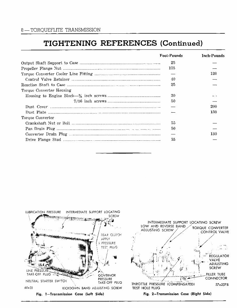
TIGHTENING R E F E R E N C E S (Continued) Foot-Pounds Inch-Pounds
Output Shaft Support to Case 25 — Propeller Flange N u t 175 — Torque Converter Cooler L ine F i t t i n g — 120
Control Valve Retainer 40 — Reaction Shaft to Case - 25 — Torque Converter Housing
Housing to Engine Block—% inch screws 30 — 7/16 inch screws.. 50 —
Dust Cover — 200 Dust Plate — 130
Torque Converter Crankshaft N u t or Bol t - 55 — Pan D r a i n P lug - - 50 —• Converter D r a i n Plug —• 130 Dr ive Flange Stud - 35 —
LUBRICATION PRESSURE INTERMEDIATE SUPPORT L O C A T I N G f SCREW \ dm
L I N E PitESSL TAKE-OFF P „
^ ^ ^ ^ ^ ^ ^ ^ ^ ^ ^ ^ ^
m i
wm.
/ REAR C L U T C H
•[ U PRESSURE * \ T E S T P L U G
/ m y y-- h^MM
i. GOVERNOR PRESSURE TAKE-OFF PLUG NEUTIAL STA«7£r< S W I T C H \
6 0 x 3 5 K I C K D O W N BAND A D J U S T I N G SCREW
Fig. 1—Transmission Case (Left Side)
I N T E R M E D I A T E SUPPORT LOCATING SCREW LOW AND REVERSE BAND ADJUSTING SCREW ,
/ y
/
H O B p i
TORQUE CONVERTER CONTROL VALVE
mm
5 REGULATOR VALVE ADJUSTING SCREW
_ FILLER T U B E CONNECTOR
THROTTLE PRESSU TEST HOLE PLUG
( C O M P E N S A T E D ) 57x237B
F ig . 2—Trcnsmission Case ( l igh t Side)
TORQUEFLITE TRANSMISSION — 9
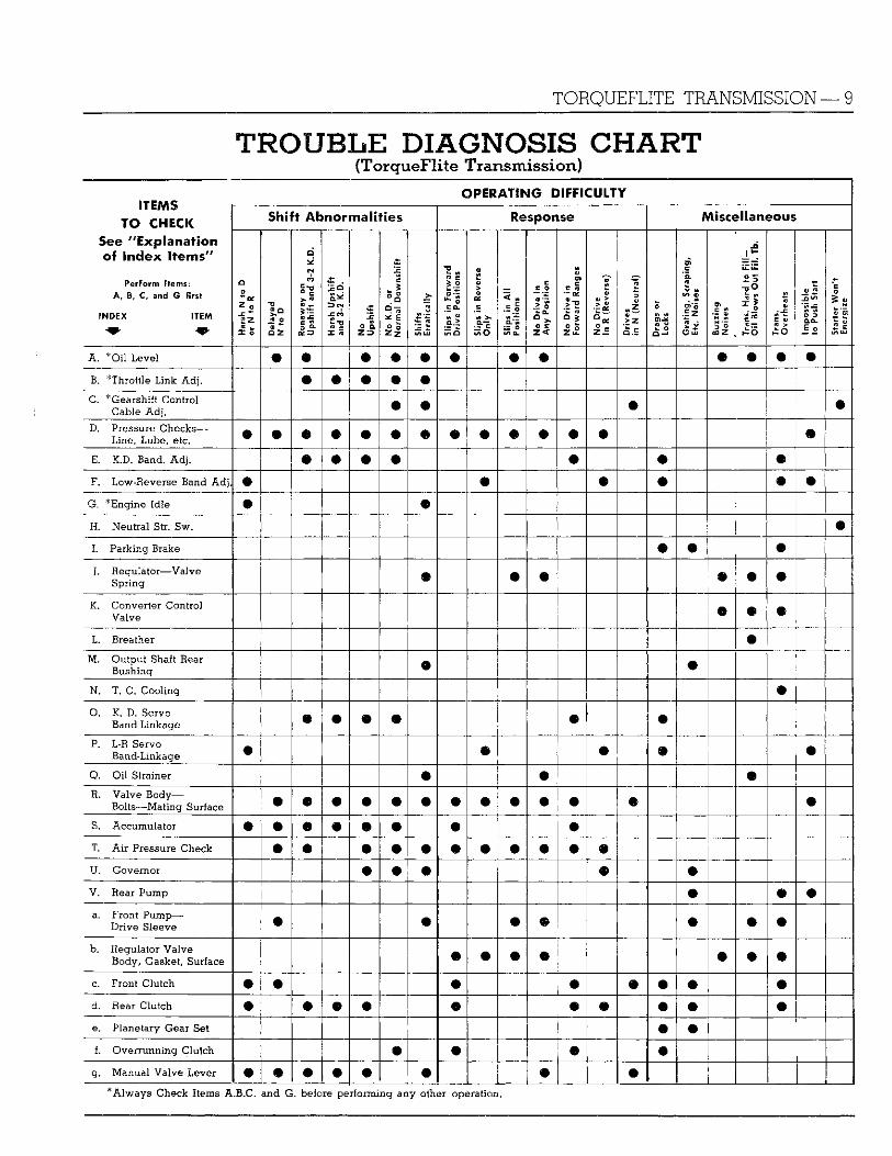
TROUBLE DIAGNOSIS CHART (TorqueFlite T r a n s m i s s i o n )
OPERATING DIFFICULTY 11 c m s
TO CHECK See "Explanation of Index i t e m s "
Perform I tems: A , B, C, and G first
I N D E X ITEM
Shift Abnormali t ies Response Miscellaneous 11 c m s
TO CHECK See "Explanation of Index i t e m s "
Perform I tems: A , B, C, and G first
I N D E X ITEM
Har
sh N
to
D
or N
to
R
Del
ayed
N
to
D
Ru
naw
ay
on
Ups
hift
and
3-2
K.D
.
Har
sh U
pshi
ft
' an
d 3-
2 K.
D.
No
Ups
hift
No
K.D
. or
N
orm
al D
owns
hift
Shift
s Er
ratic
ally
Slip
s in
Fo
rwar
d
Driv
e Po
sitio
ns
Slip
s in
Rev
erse
O
nly
Slip
s in
All
Posi
tions
No
Driv
e in
An
y Po
sitio
n
No
Driv
e in
Fo
rwar
d R
ange
s
[ N
o D
rive
In 1
(R
ever
se)
Driv
es
in N
(N
eutr
al)
Dra
gs o
r Lo
cks
Gra
ting
, Sc
rapi
ng,
Etc.
Noi
ses
Bulling
N
oise
s
Tran
s. H
ard
to F
ill-
Oil
Blo
ws
Out
Fil
. Tb.
Tran
s.
Ove
rhea
ts
impo
ssib
le
to P
ush
Star
t
Star
ter
Won
't En
ergi
ze
A . *Oil L e v e l • m • • • • • • • B. * T h r o t t l e Link A d j . m • • • C. * Gearshi f t C o n t r o l
C a b l e A d j . • • m
D. Pressure C h e c k s — L i n e , L u b e , etc. • • ® # • • o • • • • m
E. K.D. B a n d . A d j . m • m • F. L o w - R e v e r s e B a n d A d j . • • m •
G. * E n g i n e I d l e © • H . N e u t r a l Str. S w .
I. P a r k i n g Brake • • • J. R e g u l a t o r — V a l v e
S p r i n g m • m m • K. C o n v e r t e r C o n t r o l
V a l v e • m • L. Breather #
M . O u t p u t Shalt Rear B u s h i n g • m
N. T. C. C o o l i n g
O. K. D. S e r v o B a n d - L i n k a g e # • m
P. L-R S e r v o B a n d - L i n k a g e m m # m •
Q. O i l S tra iner • • m R. V a l v e B o d y —
B o l t s — M a t i n g Surface • • • • • • m • m m m • S. A c c u m u l a t o r m • • • • • • # T. A i r Pressure C h e c k • • • • m • j U . G o v e r n o r • • • m m V. Rear P u m p m • • a. F r o n t P u m p —
D r i v e S leeve • • • m m • b . R e g u l a t o r Valve
B o d y , Gasket , Surface • m m m • c. F r o n t C l u t c h m • Q • m m m • d . Rear C l u t c h m • • m • m m m • e. P l a n e t a r y G e a r Set m m f. O v e r r u n n i n g C l u t c h • m m
g . Manual Valve Lever m • • • • m m m * A l w a y s C h e c k Items A . B . C . a n d G. before p e r f o r m i n g a n y other operation.
10 —TORQUEFLITE TRANSMISSION
E R V I C E DIAGNOSIS CHART L SERVICE DIAGNOSIS C H A l f
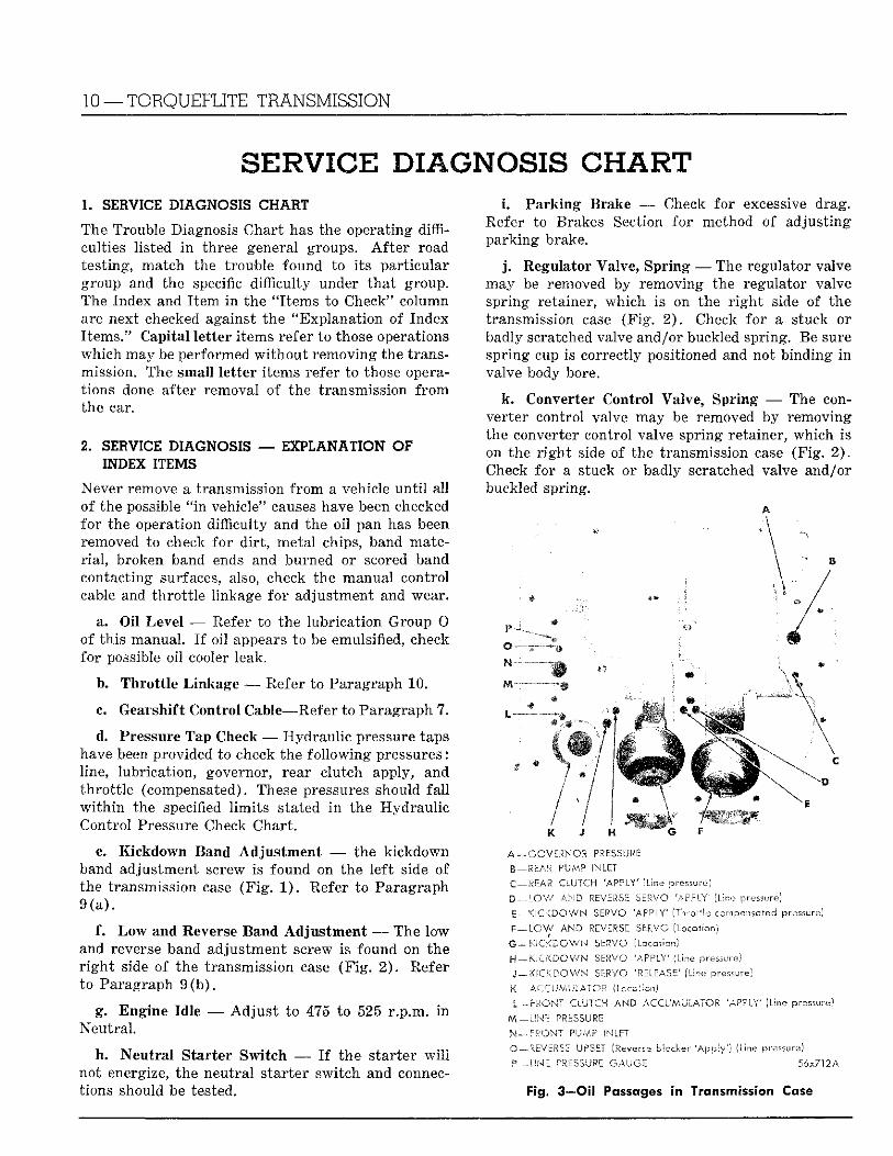
The Trouble Diagnosis Char t has the operating difficulties listed i n three general groups. A f t e r road test ing, match the trouble found to i ts par t icular group and the specific difficulty under tha t group. The Index and I t e m i n the "I tems to Check" column are next checked against the "Explanat ion of Index I tems." Capital le t ter i tems refer to those operations which may be performed w i t h o u t removing the transmission. The small le t ter i tems refer to those operations done after removal of the transmission f r o m the car.
2. SERVICE DIAGNOSIS — EXPLANATION OF INDEX ITEMS
Never remove a transmission f r o m a vehicle u n t i l al l of the possible " i n vehicle" causes have been checked for the operation difficulty and the o i l pan has been removed to check for d i r t , metal chips, band mater i a l , broken band ends and burned or scored band contacting surfaces, also, check the manual control cable and th ro t t l e linkage fo r adjustment and wear.
a. O i l Level — Refer to the lubr icat ion Group 0 of th is manual. I f oi l appears to be emulsified, check for possible oi l cooler leak.
b. Thro t t l e Linkage — Refer to Paragraph 1 0 .
c. Gearshift Control Cable—Refer to Paragraph 7.
d. Pressure Tap Check —- Hydraul ic pressure taps have been provided to check the fo l lowing pressures: line, lubricat ion, governor, rear clutch apply, and th ro t t l e (compensated). These pressures should f a l l w i t h i n the specified l im i t s stated i n the Hydrau l ic Control Pressure Check Chart .
e. K ickdown Band Adjus tment — the k ickdown band adjustment screw is found on the lef t side of the transmission case (F ig . 1 ) . Refer to Paragraph 9 ( a ) .
f. L o w and Reverse Band Adjus tment — The low and reverse band adjustment screw is found on the r i g h t side of the transmission case (F ig . 2 ) . Refer to Paragraph 9 ( b ) .
g. Engine Idle — A d j u s t to 475 to 525 r .p .m. i n Neut ra l .
h. Neutral Starter Switch — I f the s tar ter w i l l not energize, the neutra l s tar ter swi tch and connections should be tested.
L Parking Brake — • Check for excessive drag. Refer to Brakes Section for method of adjust ing park ing brake.
j . Regulator Valve, Spring — The regulator valve may be removed by removing the regulator valve spring retainer, which is on the r i g h t side of the transmission case (F ig . 2 ) . Check for a stuck or badly scratched valve and/or buckled spring. Be sure spring cup is correctly positioned and not binding i n valve body bore.
k. Converter Control Valve, Spring — The converter control valve may be removed by removing the converter control valve spring retainer, which is on the r i g h t side of the transmission case (F ig . 2 ) . Check for a stuck or badly scratched valve and/or buckled spring.
W ' -• ' ' V / •
A —GOVERNOR PRESSURE B — REAR PUMP INLET
C —REAR CLUTCH 'APPLY' (Line pressure)
D — LOW AND REVERSE SERVO 'APPLY' (Line pressure)
E—KICKDOWN SERVO 'APPLY' (Throttle compensated pressure)
F — LOW AND REVERSE SERVO (Location)
G—KICKDOWN SERVO (Location)
H —KICKDOWN SERVO 'APPLY' (Line pressure) J — KICKDOWN SERVO 'RELEASE' (Line pressure)
K —ACCUMULATOR (Location)
I — FRONT CLUTCH AND ACCUMULATOR 'APPLY' (Line pressure)
M —LINE PRESSURE N — FRONT PUMP INLET
O—-REVERSE UPSET (Reverse blocker 'Apply') (Line pressure)
P—LINE ^'USZJRE GAUGE 56x712A
Fig. 3—Oil Passages in Transmission Case
TORQUEFLITE TRANSMISSION — 11
1. Breather — Check to determine whether the breather is free of d i r t and undercoating.
m . Output Shaft Rear Bushing — Check for rough, scored or worn bushing.
n . Torque Converter — Check oil cooler lines for being bent, kinked or having loose connections.
o. Kickdown Servo, Band and Linkage — Check for broken seal r ings, stuck servo pistons or broken linkage.
p. Low and Reverse Servo, Bank and Linkage — Check for t o r n seal, broken band and/or linkage.
q. Oi l Strainer — Check for possible a i r leakage or clogged screen.
r . Valve Body A t t ach ing Bolts and M a t i n g Surface — Check for loose bolts, burrs or scratches on ma t ing surfaces. Clean valve body assembly. Check for stuck valves, d i r t , scratched valves or body, and burrs on valves. Torque valve body bolts to specifications.
s. Accumulator — Check accumulator piston for s t icking, rough bore i n case, and/or r ings.
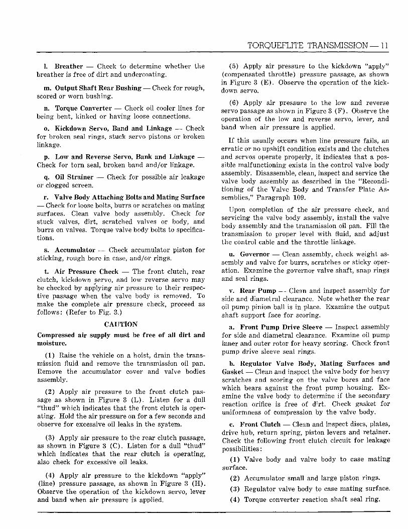
t . A i r Pressure Check — The f ron t clutch, rear clutch, k ickdown servo, and low reverse servo may be checked by applying a i r pressure to the i r respect ive passage when the valve body is removed. To make the complete a i r pressure check, proceed as fol lows: (Refer to F i g . 3.)
C A U T I O N
Compressed air supply must be free of a l l d i r t and moisture.
(1) Raise the vehicle on a hoist, dra in the transmission fluid and remove the transmission oil pan. Remove the accumulator cover and valve bodies assembly.
( 2 ) A p p l y a i r pressure to the f ron t clutch passage as shown i n F igure 3 ( L ) . L i s t en for a dul l " t h u d " wh ich indicates tha t the f ron t clutch is operat ing. Hold the a i r pressure on for a few seconds and observe for excessive oi l leaks i n the system.
(3) A p p l y air pressure to the rear clutch passage, as shown i n F igure 3 ( C ) . L is ten fo r a dul l " t h u d " which indicates t ha t the rear clutch is operating, also check fo r excessive oil leaks.
(4) A p p l y a i r pressure to the k ickdown "apply" (line) pressure passage, as shown i n Figure 3 ( H ) . Observe the operation of the k ickdown servo, lever and band when a i r pressure is applied.
(5) A p p l y air pressure to the kickdown "apply" (compensated th ro t t l e ) pressure passage, as shown i n F igure 3 ( E ) . Observe the operation of the kick-down servo.
(6) A p p l y air pressure to the low and reverse servo passage as shown i n Figure 3 ( F ) . Observe the operation of the low and reverse servo, lever, and band when a i r pressure is applied.
I f th is usually occurs when line pressure fails, an errat ic or no upshift condition exists and the clutches and servos operate properly, i t indicates tha t a possible malfunct ioning exists i n the control valve body assembly. Disassemble, clean, inspect and service the valve body assembly as described i n the "Recondit ion ing of the Valve Body and Transfer Plate Assemblies," Paragraph 109.
Upon completion of the air pressure check, and servicing the valve body assembly, instal l the valve body assembly and the transmission oil pan. F i l l the transmission to proper level w i t h fluid, and adjust the control cable and the th ro t t l e linkage.
u . Governor — Clean assembly, check weight assembly and valve for burrs , scratches or st icky operation. Examine the governor valve shaft, snap rings and seal r ings.
v. Rear Pump — Clean and inspect assembly for side and diametral clearance. Note whether the rear oi l pump pinion ball is i n place. Examine the output shaft support face for scoring.
a. F ron t Pump Dr ive Sleeve — Inspect assembly for side and diametral clearance. Examine oil pump inner and outer ro tor for heavy scoring. Check f ron t pump drive sleeve seal r ings.
b. Regulator Valve Body, M a t i n g Surfaces and Gasket — Clean and inspect the valve body for heavy scratches and scoring on the valve bores and face which bears against the f ron t pump housing. Examine the valve body to determine i f the secondary reaction orifice is free of d i r t . Check gasket for uniformness of compression by the valve body.
c. F ron t Clutch — Clean and inspect discs, plates, dr ive hub, r e tu rn spring, piston levers and retainer. Check the fol lowing f ron t clutch c i rcui t fo r leakage possibilit ies:
(1) Valve body and valve body to case ma t ing surface.
( 2 ) Accumulator small and large piston rings.
( 3 ) Regulator valve body to case ma t ing surface.
( 4 ) Torque converter reaction shaft seal r i n g .
ENGINE CRANKSHAFT
j TORQUE CONVERTER OVERRUNNING CLUTCH
TORQUE CONVERTER IMPELLER
\ FRONT OIL PUMP HOUS ING DUST SEAL
\ INPUT SHAFT ASSEMBLY
REAR CLUTCH PRESSURE PLATE
/ K I C K D O W N BAND
/ / INTERMEDIATE SUPPORT ASSEMBLY 1 ' 1 OVERRUNNING CLUTCH ASSEMBLY
1 LOW-REVERSE BAND
; LOW-REVERSE BAND DRUM
/ / REVERSE ANNULUS GEAR
/ / / / TRANSMISSION CASE
, j j K I C K D O W N ANNULUS GEAR
/ I I I OUTPUT SHAFT SUPPORT
REAR OIL PUMP
/ / EXTENSION
/ / GOVERNOR ASSEMBLY
SPEEDOMETER PINION
/ / / / S R E A R CLUTCH ASSEMBLY
' j / / FRONT CLUTCH PRESSURE PLATE
/ / OIL STRAINER:
/ REVERSE SUN GEAR TORQUE CONVERTER REACTION SHAFT / / LOW-REVERSE PLANET PINION CARRIER ASSEMBLY
FRONT OIL PUMP / VALVE BODIES A N D TRANSFER PLATE ASSEMBLY
TORQUE CONVERTER STATOR INTERMEDIATE SHAFT ASSEMBLY
TORQUE CONVERTER TURBINE
HAND BRAKE ASSEMBLY
56x707C
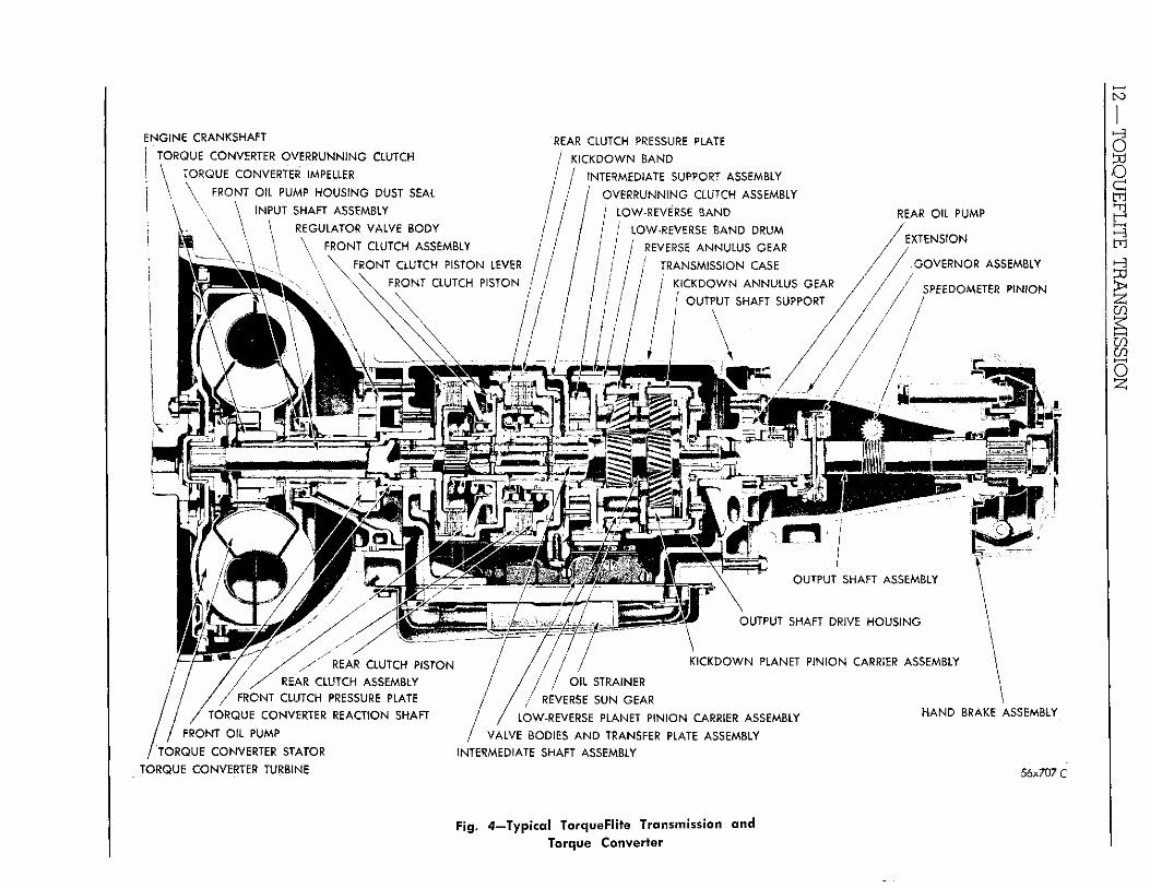
Fig. 4—Typical TorqueFlite Transmission and Torque Converter
TORQUEFLITE TRANSMISSION—13
(5) I n p u t shaft small and large seal r ings .
(6 ) Intermediate shaft No. 1, 2, and 8 seal r ings.
(7 ) F r o n t clutch oil feed tube.
(8) F ron t clutch piston inner and outer seal r ings.
(9) F ron t clutch retainer ball check.
d. Rear Clutch — Clean and inspect discs, plates, r e tu rn spr ing and piston. Check the fo l lowing rear clutch c i rcui t for leakage possibilities.
(1) Valve body and valve body to case ma t ing surface.
(2) Output shaft support to case ma t ing surface.
(3 ) Output shaft small and large seal r ings.
(4) Intermediate shaft No. 4, 5, and 6 seal r ings .
(5) Rear clutch oi l feed tube.
( 6 ) Sun gear rear clutch seal r ings.
(7) Rear clutch piston inner and outer seal r ings.
( 8 ) Rear clutch retainer ball check.
(9 ) Kickdown piston rod guide seal r i n g and rod guide to kickdown rod fit.
(10) Large kickdown piston seal r i ng .
e. Planetary Gear Set — Clean and inspect gear set fo r worn th rus t washers, nicked or rough gear teeth, and excessive pinion end clearance.
f. L o w Speed Over-Running Clutch — Clean and inspect the overrunning clutch assembly f r o m b r i n -nelled rollers and/ or cam and improperly assembled rollers or springs. Check the cam roller ramps fo r being worn .
g. Manual Valve Lever — A loose or badly worn manual valve lever cam should be replaced. I f loose, i t may be silver soldered only so as not to require h igh temperatures tha t could destroy i ts hardness, otherwise i t should be replaced.
T O R Q U E F L I T E 3. TORQUEFLITE OPERATING PRINCIPLES
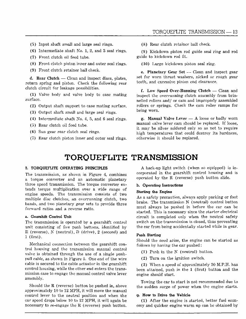
The transmission, as shown i n Figure 4, combines a torque converter and an automatic planetary three speed transmission. The torque converter extends torque mul t ip l ica t ion over a wide range of engine speeds. The transmission consists of two mul t ip le disc clutches, an overrunning clutch, two bands, and two planetary gear sets to provide three fo rward ratios and a reverse ra t io .
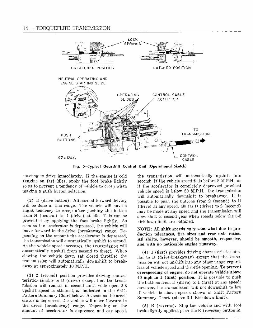
a. Gearshift Control Unit The transmission is operated by a gearshift control uni t consisting of five push buttons, identified by R (reverse), N (neut ra l ) , D (d r ive ) , 2 (second) and 1 ( f i r s t ) .
Mechanical connection between the gearshift cont ro l housing and the transmission manual control valve is obtained th rough the use of a single push-pull cable, as shown i n Figure 5. One end of the wi re cable is secured to the cable actuator i n the gearshif t control housing, whi le the other end enters the transmission case to engage the manual control valve lever assembly.
Should the R (reverse) but ton be pushed i n , above approximately 10 to 12 M P H , i t w i l l move the manual control lever to the neutral position and when the car speed drops below 10 to 12 M P H , i t w i l l again be necessary to re-engage the R (reverse) push bu t ton .
TRANSMISSION A back-up l i g h t switch (when so equipped) is i n
corporated in the gearshift control housing and is operated by the R (reverse) push bu t ton slide.
b. Operating Instructions
Starting the Engine As a safety precaution, always apply park ing or foot brake. The transmission N (neutral) control bu t ton must always be pushed in before the car can be started. This is necessary since the starter electrical c i rcui t is completed only when the neutral safety switch on the transmission is closed, thus preventing the car f r o m being accidentally started while in gear.
Push Starting Should the need arise, the engine can be started as follows by having the car pushed:
(1) Push in the N (neutral) but ton .
(2) T u r n on the ign i t ion switch.
(3 ) When a speed of approximately 20 M.P .H. has been attained, push in the 1 ( f i rs t ) but ton and the engine should start .
Towing the car to s tar t is not recommended due to the sudden surge of power when the engine starts .
g. How to Drive the Vehicle (1) A f t e r the engine is started, better fuel econ
omy and quicker engine w a r m up can be obtained by
14 —TORQUEFLITE TRANSMISSION
LOCK
UNLATCHED POSITION LATCHED POSITION
NEUTRAL OPERATING AND ENGINE STARTING SLIDE
CONTROL CABLE ACTUATOR
PUSH BUTTONS
TO TRANSMISSION
57x l74A
Fig. 5—Typical Gearshift Control Unit (Operational Sketch)
CONTROL CABLE
s ta r t ing to drive immediately. I f the engine is cold (engine on fast id le) , apply the foot brake l i g h t l y so as to prevent a tendency of vehicle to creep when mak ing a push but ton selection.
( 2 ) D (drive bu t ton ) . A l l normal fo rward d r iv ing w i l l be done i n this range. The vehicle w i l l have a s l ight tendency to creep after pushing the bu t ton f r o m N (neutral) to D (dr ive) at idle. This can be prevented by applying the foot brake l i g h t l y . As soon as the accelerator is depressed, the vehicle w i l l move fo rward i n the drive (breakaway) range. Depending on the amount the accelerator is depressed, the transmission w i l l automatical ly upshift to second. As the vehicle speed increases, the transmission w i l l automatical ly upshif t f r o m second to direct. When slowing the vehicle down (at closed th ro t t l e ) the transmission w i l l automatically downshif t to breakaway at approximately 10 M . P . H .
( 3 ) 2 (second) posit ion provides d r i v i n g characteristics s imilar to D (dr ive) except t ha t the transmission w i l l remain i n second u n t i l wide open 2-3 upshif t speed is attained, as indicated i n the Shi f t Pa t te rn Summary Char t below. As soon as the accelerator is depressed, the vehicle w i l l move f o r w a r d i n the drive (breakaway) range. Depending on the amount of accelerator is depressed and car speed,
the transmission w i l l automatically upshift into second: I f the vehicle speed falls before 8 M.P.H. , or i f the accelerator is completely depressed provided vehicle speed is below 30 M.P.H. , the transmission w i l l automatically downshift to breakaway. I t is possible to push the buttons f r o m 2 (second) to D (dr ive) at any speed. Shifts D (drive) to 2 (second) may be made at any speed and the transmission w i l l downshif t to second gear when speeds below the 3-2 k ickdown l i m i t are obtained.
N O T E : A l l sh i f t speeds vary somewhat due to production tolerances, t i r e sizes and rear axle ratios. A l l shif ts , however, should be smooth, responsive, and w i t h no noticeable engine runaway.
(4 ) 1 ( f i r s t ) provides d r i v i n g characteristics simi l a r to D (drive-breakaway) except tha t the transmission w i l l not upshift into any other range regardless of vehicle speed and th ro t t l e opening. To prevent overspeeding of engine, do not operate vehicle above 40 mph i n 1 ( f i r s t ) position. I t is possible to push the buttons f r o m D (drive) to 1 (f i rs t) at any speed; however, the transmission w i l l not downshift to low i f vehicle is above speeds shown i n Shif t Pa t te rn Summary Chart (above 3-1 Kickdown l i m i t ) .
(5) R (reverse). Stop the vehicle and w i t h foot brake l i g h t l y applied, push the R (reverse) button, i n .
TORQUEFLITE TRANSMISSION — 15
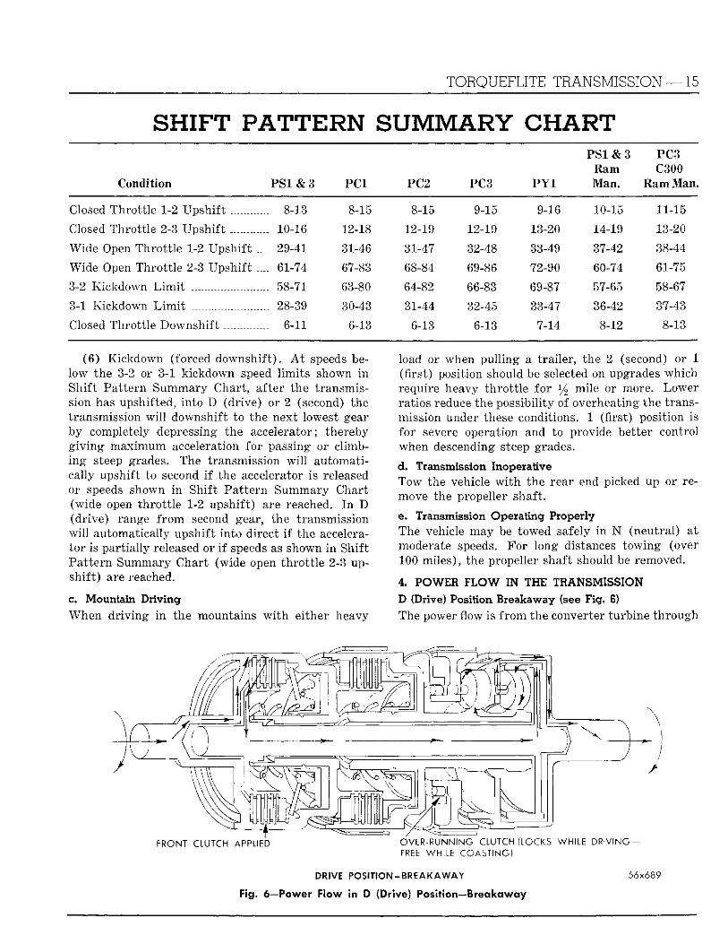
SHIFT PATTERN SUMMARY CHART P S I & 3 PC3
Ram C300 Condition P S 1 & 3 P C I PC2 PC3 P Y 1 Man. Ram Man.
Closed Thro t t le 1-2 Upshi f t 8-13 8-15
Closed Thro t t le 2-3 Upshi f t 10-16 12-18
Wide Open Thro t t l e 1-2 Upshi f t .... 29-41 31-46
Wide Open Thro t t l e 2-3 Upshi f t .... 61-74 67-83
3-2 Kickdown L i m i t 58-71 63-80
3-1 Kickdown L i m i t 28-39 30-43
Closed Throt t le Downshi f t 6-11 6-13
(6) Kickdown (forced downsh i f t ) . A t speeds below the 3-2 or 3-1 kickdown speed l imi t s shown i n Shif t Pat tern Summary Chart , after the transmission has upshifted, in to D (dr ive) or 2 (second) the transmission w i l l downshift to the next lowest gear by completely depressing the accelerator; thereby g i v i n g max imum acceleration for passing or climbi n g steep grades. The transmission w i l l automatically upshift to second i f the accelerator is released or speeds shown i n Shif t Pa t te rn Summary Chart (wide open th ro t t l e 1-2 upshif t ) are reached. I n D (dr ive) range f r o m second gear, the transmission w i l l automatically upshif t into direct i f the accelerator is par t ia l ly released or i f speeds as shown i n Shif t Pa t te rn Summary Chart (wide open th ro t t l e 2-3 upsh i f t ) are reached.
c. Mountain Driving When d r iv ing i n the mountains w i t h either heavy
8-15 9-15 9-16 10-15 11-15
12-19 12-19 13-20 14-19 13-20
31-47 32-48 33-49 37-42 38-44
68-84 69-86 72-90 60-74 61-75
64-82 66-83 69-87 57-65 58-67
31-44 32-45 33-47 36-42 37-43
6-13 6-13 7-14 8-12 8-13
load or when pul l ing a t rai ler , the 2 (second) or 1 (f i rs t ) position should be selected on upgrades which require heavy th ro t t l e fo r y2 mile or more. Lower ratios reduce the possibil i ty of overheating the transmission under these conditions. 1 (f irst) position is for severe operation and to provide better control when descending steep grades.
d. Transmission Inoperative Tow the vehicle w i t h the rear end picked up or remove the propeller shaft.
e. Transmission Operating Properly The vehicle may be towed safely i n N (neutral) at moderate speeds. For long distances towing (over 100 miles) , the propeller shaft should be removed.
4. POWER F L O W IN THE TRANSMISSION D (Drive) Position Breakaway (see Fig. 6) The power flow is f r o m the converter turbine th rough
FRONT CLUTCH APPLIED OVER-RUNNING CLUTCH (LOCKS WHILE D R I V I N G -FREE WHILE COASTING)
DRIVE P O S I T I O N - B R E A K A W A Y
Fig. 6—Power Flow in D (Drive) Position—Breakaway
56x689
16 —TORQUEFLITE TRANSMISSION
5 6 x 6 9 0
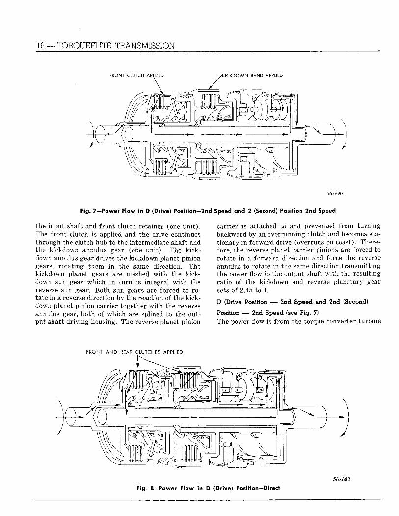
Fig. 7—Power Flow in D (Drive) Position—2nd Speed and 2 (Second) Position 2nd Speed
carrier is attached to and prevented f r o m t u r n i n g backward by an overrunning clutch and becomes stat ionary in fo rward drive (overruns on coast). Therefore, the reverse planet carrier pinions are forced to rotate i n a fo rward direction and force the reverse annulus to rotate i n the same direction t r ansmi t t i ng the power flow to the output shaft w i t h the resul t ing ra t io of the kickdown and reverse planetary gear sets of 2.45 to 1.
D (Drive Position — 2nd Speed and 2nd (Second)
Position — 2nd Speed (see F ig . 7)
The power flow is f r o m the torque converter turbine
56x688
Fig. 8—Power Flow in D (Drive) Position—Direct
the input shaft and f ron t clutch retainer (one u n i t ) . The f ron t clutch is applied and the dr ive continues th rough the clutch hub to the intermediate shaft and the k ickdown annulus gear (one u n i t ) . The k ick-down annulus gear drives the kickdown planet pinion gears, ro t a t i ng them i n the same direction. The k ickdown planet gears are meshed w i t h the k ick-down sun gear w h i c h i n t u r n is in tegral w i t h the reverse sun gear. B o t h sun gears are forced to rotate i n a reverse direct ion by the reaction of the kick-down planet pinion carrier together w i t h the reverse annulus gear, both of wh ich are splined to the output shaft d r i v i n g housing. The reverse planet pinion
F R O N T A N D R E A R C L U T C H E S A P P L I E D
TORQUEFLITE TRANSMISSION—17
FRONT CLUTCH APPLIED LOW AND REVERSE BAND APPLIED
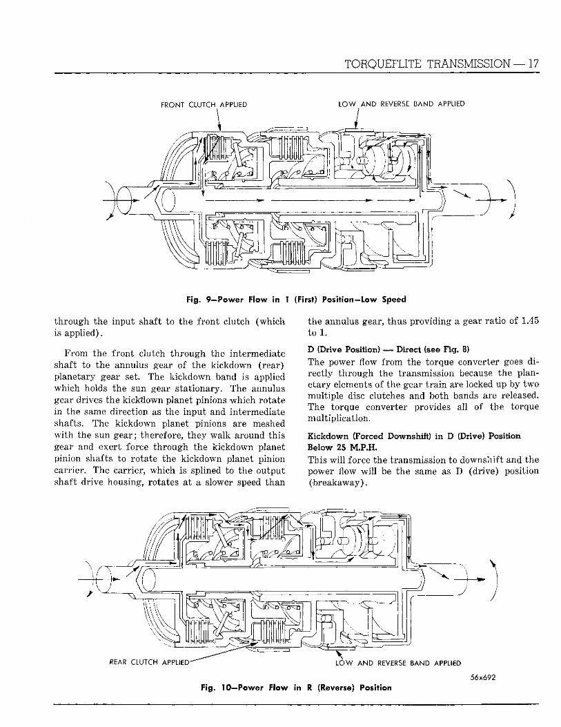
Fig. 9—Power Flow in 1 (First) Position—low Speed
th rough the input shaft to the f ron t clutch (which is applied).
F r o m the f ron t clutch th rough the intermediate shaft to the annulus gear of the kickdown (rear) planetary gear set. The k ickdown band is applied which holds the sun gear stat ionary. The annulus gear drives the kickdown planet pinions wh ich rotate i n the same direction as the input and intermediate shafts. The kickdown planet pinions. are meshed w i t h the sun gear; therefore, they walk around th is gear and exert force th rough the k ickdown planet pinion shafts to rotate the k ickdown planet pinion carrier. The carrier, which is splined to the output shaft drive housing, rotates at a slower speed than
the annulus gear, thus provid ing a gear ra t io of 1.45 to 1.
D (Drive Position) — Direct (see Fig. 8) The power flow f r o m the torque converter goes d i rect ly th rough the transmission because the planetary elements of the gear t r a i n are locked up by two mult ip le disc clutches and both bands are released. The torque converter provides all of the torque mul t ip l ica t ion .
Kickdown (Forced Downshift) i n D (Drive) Position Below 25 VLPJSL This w i l l force the transmission to downshift and the power flow w i l l be the same as D (dr ive) position (breakaway) .
56x692 Fig. 10—Power Flow in R (Reverse) Position
18 —TORQUEFLITE TRANSMISSION
Kickdown (Forced 3-2 Downshift) i n D (Drive) Position 25 to 70 M .P .H. This w i l l force the transmission to downshift and the power flow w i l l be the same as D (dr ive) position 2nd speed.
1 (First Position) — First Speed (see Fig. 9) I n 1 (f i rs t ) position the power flow is the same as D (drive) position (breakaway) or 2 (second) posit ion (breakaway) w i t h one exception, the low-reverse band is applied, locking the overrunning clutch to provide engine braking.
R (Reverse) Position (see Fig. 10) The rear clutch and the low-reverse band are applied. A l l other f r i c t i on elements are released. The power flow is f r o m the torque converter turbine th rough the inpu t shaft to the rear clutch hub (par t of the f ron t clutch re ta iner ) . The rear clutch is splined to the reverse sun gear. The carrier of the reverse ( f ron t ) planetary gear set is held stat ionary by the low-reverse band; therefore, the se.t acts as a reverse t r a i n th rough the reverse planet pinions to the reverse annulus (which is splined to the output shaft dr ive housing) and provides a reverse ra t io of 2.20 to 1.
N (Neutral) Position
A l l f r i c t ion elements are released. Hence, there is no drive connection between the engine and the rear wheels.
Power Flow Summary The chart summarizes power flow conditions i n the various ranges as regards to gear t r a i n elements i n volved and the ratios obtained.
5. THE HYDRAULIC CONTROL SYSTEM
The hydraulic control system has four impor tant functions to perform.
The pressure supply system, the clutches and band servos, the pressure regula t ing valves and the flow control valves.
a. The Pressure Supply System
Front Pump Under al l normal operating conditions (up to a forwa rd speed of approximately 35 mph) the f ron t pump, driven at engine speed, provides oi l needed for torque converter pressure, control pressures, and lubricat ion.
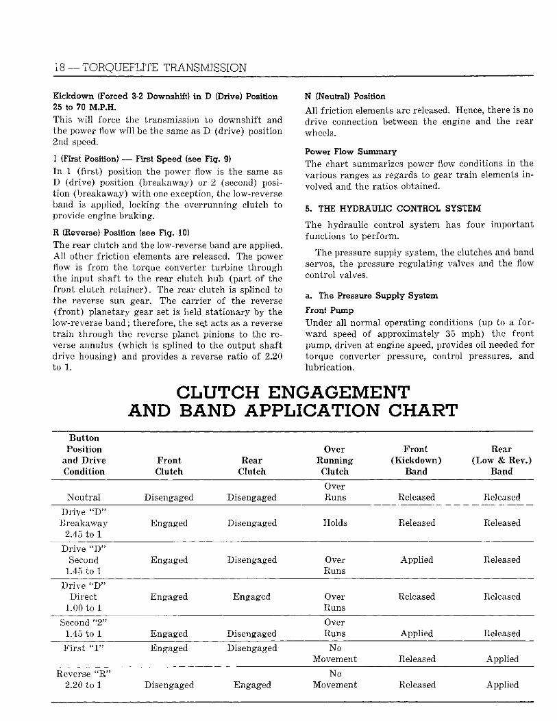
C L U T C H ENGAGEMENT AND BAND APPLICATION CHART
Button Position
and Drive Condition
Front Clutch
Rear Clutch
Over Running
Clutch
Front (Kickdown)
Band
Rear (Low & Rev.)
Band
Neut ra l Disengaged Disengaged Over Runs Released Released
Dr ive "D" Breakaway
2.45 to 1 Engaged Disengaged Holds Released Released
Dr ive "D" Second
1.45 to 1 Engaged Disengaged Over
Runs Appl ied Released
Dr ive "D" Direct
1.00 to 1 Engaged Engaged Over
Runs Released Released
Second u2" 1.45 to 1 Engaged Disengaged
Over Runs Applied Released
F i r s t " 1 " Engaged Disengaged No Movement Released Applied
Reverse " R " 2.20 to 1 Disengaged Engaged
No Movement Released Applied
TORQUEFLITE TRANSMISSION—19
The f ront pump delivers oi l at approximately 90 psi to fu l f i l l these conditions at al l engine speeds above approximately 700 rpm. I n reverse, the f ron t pump pressure is increased to approximately 225 psi i n order to handle the h igh torque loads imposed dur ing reverse operation.
Hear Pump The rear pump (smaller than the f ron t pump and driven by the output shaft) furnishes all of the oi l required by the transmission in normal d r iv ing at all vehicle speeds above approximately 35 mph.
b. Clutches and Band Servos
Front Clutch The f ron t clutch t ransmits f u l l engine and converter torque i n all fo rward drive positions.
I n order to develop the required capacity, a system of eight levers is used to actuate the clutch apply plate.
Rear Clutch The rear clutch locks the gear t r a i n for direct drive operation in the fo rward range and t ransmits f u l l input torque to the gear t r a i n i n reverse operation.
Kickdown Servo The kickdown piston actuates the k ickdown band th rough the k ickdown lever, s t ru t , and anchor, holding the sun gear of the rear planetary set stat ionary and resul t ing i n a f o r w a r d ra t io of 1.45 to 1 th rough the rear planetary gear set.
Low-Reverse Servo The low-reverse servo has two functions which are performed independently. The f irs t reverse servo piston is moved hydraul ical ly to apply the first reverse band th rough the f irs t reverse band lever, s t ru t , and anchor (F ig . 10) .
Accumulator A n accumulator helps to cushion the f ront clutch engagement when a fo rward drive but ton is pushed in and the application of the k ickdown band i n the upshift f r o m breakaway to second. I t is connected in parallel and to the passage which supplies line pressure to the apply side of the k ickdown servo.
c. Pressure Regulating Valves
Regulator Valve The regulator valve controls line pressure at a value of approximately 90 psi for all operating conditions except reverse.
For reverse operation, oi l must be at a pressure o f 225 psi. This is accomplished by shu t t ing off the
source of line pressure to the regulator valve secondary reaction area, w i t h the result tha t a l ine pressure of 225 psi, applied to the p r imary reaction area, is required to overcome the force of the regulator valve spring.
Torque Converter Control Valve This valve maintains an oil pressure of approximately 30 psi w i t h i n the torque converter. Oi l is fed f r o m the regulator valve through a res t r ic t ing hole in the regulator valve body to the torque converter.
Oil is routed f r o m the torque converter control valve th rough the transmission lubricat ion system to lubricate the gear t r a i n at approximately 10 to 30 psi pressure.
Governor Valve The governor valve assembly t ransmits a hydraul ic pressure to the transmission which is proportional to car speed. This governed pressure, i n conjunction w i t h th ro t t l e pressure, controls upshift and downshif t speeds.
Throttle Valve The th ro t t l e valve assembly t ransmits a hydraul ic pressure to the transmission which is proport ional to the amount of t h ro t t l e opening.
The th ro t t l e valve allows oi l to flow f r o m the line pressure por t to the th ro t t l e pressure port , which is connected by a passage to the reactions area of the th ro t t l e valve.
Thro t t l e pressure w i l l va ry w i t h the amount of carburetor th ro t t l e opening f rom a value of 0 (zero) pressure at closed th ro t t l e to a value of approximately 90 psi at wide open thro t t le .
Throttle Compensator Valve The th ro t t l e compensator valve amplifies the variations i n th ro t t l e pressure. Thro t t l e compensator pressure w i l l va ry w i t h the amount of carburetor t h ro t t l e opening f r o m a value of approximately 10 to 16 psi ( w i t h the 1 piece valve body) at closed th ro t t l e to a value of 90 psi at approximately % thro t t l e .
d. Flow Control Valves
Front and Rear Pump Check Valves The f ron t pump check valve prevents back flow f r o m the rear pump into the pressure side of the pump when the pump is ei ther s tat ionary or merely circul a t ing oi l at a very low pressure. The check valve separates f ront and rear pump.
Manual Valve The manual valve obtains the different transmission dr ive ranges as selected by the vehicle operator.
20 — TORQUEFLITE TRANSMISSION
Reverse Blocker Valve The reverse blocker valve mechanically blocks the manual valve f r o m moving Into reverse posit ion to prevent accidental reverse engagement above approximately 10-15 mph.
1- 2 Sh i t Valve This valve determines whether the transmission is either i n first gear ra t io or second gear ra t io , depending upon whether the valve is i n the upshifted or down-shifted position.
2- 3 Shift Valve This sh i f t valve automatical ly shifts the transmission f r o m intermediate to direct gear.
1-2 Relay Valve This valve provides for a quick application and release of the k ickdown band and rear clutch at low speeds while smoothing out the i r apply and release at h igh speeds.
Kickdown Valve The kickdown valve makes possible a forced downshi f t f r o m direct to second — second to breakaway and direct to breakaway by depressing the accelerato r pedal past the detent "feel" near wide open th ro t t l e .
Shuttle Valve, Shuttle Valve Plug, and Servo Pressure Bleed Valve The shutt le valve has two separate functions and performs each independently of the other. The first
is tha t of providing fast release of the kickdown band, and delayed smooth rear clutch engagement when the dr iver makes a " l i f t - f o o t " upshift f r o m second to direct.
The second funct ion of the shutt le valve is to regulate the application of the kickdown piston when making h igh speed (above approximately 30 mph) kickdowns.
e. Operational Summary W i t h the D (drive) but ton pushed in , the manual valve is positioned to govern the f u l l range of operat ion of the transmission. W i t h the manual valve In the drive position, the f ron t clutch is engaged and the transmission w i l l t r ansmi t dr ive torque i n breakaway.
Pushing In the 2 (second) bu t ton of the control un i t moves the manual valve so tha t line pressure is directed to the kickdown ci rcui t of the 2-3 shi f t valve.
Pushing i n the 1 (f i rs t) bu t ton of the control un i t positions the manual valve so tha t line pressure Is directed to the kickdown ci rcui t of the 1-2 shi f t valve.
Pushing i n the N (neutral) but ton moves the manual valve to a position which shuts off o i l flow to the valve body. The torque converter and lubricat ion system remains pressurized.
Pushing i n the R (reverse) but ton of the control un i t positions the manual valve so tha t oi l pressure is directed to apply the rear clutch and low-reverse band.
MAINTENANCE, ADJUSTMENTS AND T E S T S C A U T I O N
For safety reasons and to prevent possible damage to the transmission . . . wide open throttle stall test operations should not be attempted under any circumstances.
Good transmission operation depends direct ly upon good engine performance. Therefore, i t is of utmost importance tha t the engine is operat ing at f u l l efficiency and at proper idle speed before a t t empt ing to diagnose or correct any transmission operation. The engine and transmission should be warmed up to operating temperature. A short drive, approximately five to ten miles, w i t h frequent stops and starts w i l l produce normal operating temperatures to the transmission and engine. Check o i l level.
A l l shifts and kickdowns should occur w i t h i n the
speed ranges given in the Shif t Pat tern Summary Chart .
N O T E : Al l shift speeds may vary somewhat due to production tolerances, type of engine, rear axle ratios and tire sizes. Al l shifts, however, should be smooth, responsive and with no noticeable engine runaway.
6* OIL LEAKS
Leaks Which may be Corrected with Transmission in Vehicle Transmission output shaft rear bushing oil seal. Extension gasket, Speedometer drive pinion assembly. Oi l pan to filler tube connector. Oil pan to transmission case. Regulator valve and torque converter cont r o l valve spring retainers. Regulator valve adjusti n g screw. Gearshift control cable seal r i n g and housing gasket. Governor, l i n , lubricat ion, rear
TORQUEFLITE TRANSMISSION — 21
clutch apply and th ro t t l e (compensated) pressure check plug's In transmission case or support (pressure test holes) . Neu t ra l s ta r t ing swi tch. Oil cooler connections.
I f oi l is found inside the torque converter housing, determine whether i t is Automat ic Transmission F lu id or engine oil . Check the torque converter dra in p lug for tightness.
Leaks at these locations should be corrected, regardless of how l i gh t . Correct by t igh ten ing loose screws or plugs. Where th is does not remedy the s i tuat ion, replace the necessary gaskets, seals or plugs.
Leaks Requiring Removal of Transmission from Vehicle Damaged transmission case. Damaged f ron t o i l pump housing. F ron t oil pump housing screws or damaged sealing washers. F r o n t oil pump housing seal (located i n the large f ron t bore of the f ron t o i l pump housing) . Torque converter. Leaks at these locations may be corrected by t igh ten ing loose bolts or replacing damaged or fau l ty parts.
7. GEARSHIFT CONTROL CABLE ADJUSTMENT
Gearshift Control Cable Adjustment (Fig. 11) (1) Engage the R (reverse) push bu t ton and dra in
approximately two quarts of fluid f r o m the transmission.
(2 ) Remove the control cable adjustment wheel lock screw.
(3) Remove the neutral s t a r t ing switch, cupped washer and seal.
( 4 ) Have an assistant f i rmly hold the R (reverse) bu t ton u n t i l the transmsision end of cable adjustment has been completed.
THRO':; ' ; . : : L I N K * 3c
" O " RING SEAL
4
CABLE GUIDE
CABLE HOUSING
Ifi /
4f
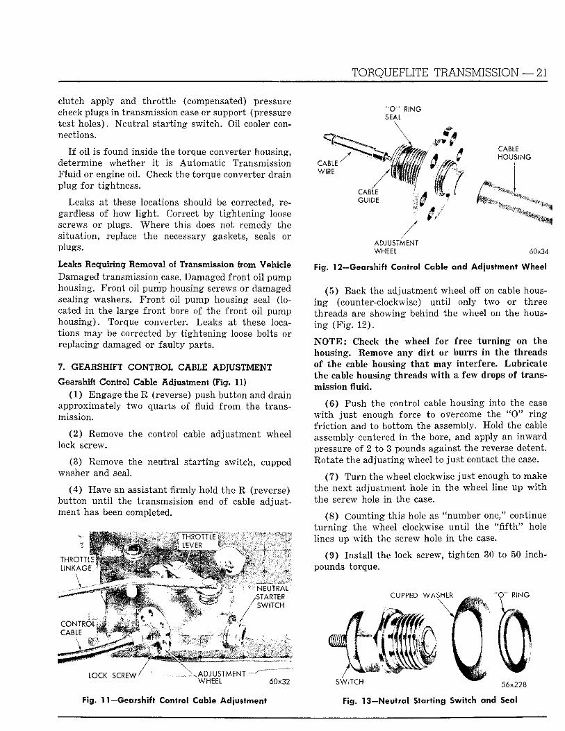
ADJUSTMENT WHEEL 60x34
Fig. 12—Gearshift Control Cable and Adjustment Wheel
(5 ) Back the adjustment wheel off on cable housing (counter-clockwise) u n t i l only two or three threads are showing behind the wheel on the housing (F ig . 12) .
N O T E : Check the wheel fo r free tu rn ing on the housing. Remove any d i r t or burrs i n the threads of the cable housing tha t may interfere. Lubr ica te the cable housing threads w i t h a few drops of transmission fluid.
( 6 ) Push the control cable housing into the case w i t h j u s t enough force to overcome the " O " r i n g f r i c t i on and to bot tom the assembly. Hold the cable assembly centered i n the bore, and apply an inward pressure of 2 to 3 pounds against the reverse detent. Rotate the adjust ing wheel to j u s t contact the case.
(7) T u r n the wheel clockwise j u s t enough to make the next adjustment hole i n the wheel line up w i t h the screw hole i n the case.
(8) Count ing th is hole as "number one," continue t u r n i n g the wheel clockwise u n t i l the " f i f t h " hole lines up w i t h the screw hole i n the case.
(9 ) Ins ta l l the lock screw, t igh ten 30 to 50 inch-pounds torque.
C O N T R O L C A B L E
LOCK S C R E W /
NEUTRAL STARTER
/ SWITCH
A D J U S T M E N T WHEEL 60x32 SWITCH
CUPPED WASHER " O " R ING
56x228
Fig. 11 —Gearshift Control Cable Adjustment Fig. 13—Neutral Starting Switch and Seal
22 — T O R Q U E F L I T E T R A N S M I S S I O N
(10) Ins ta l l the neutral s ta r t ing switch as outlined i n Paragraph 7. Refill the transmission w i t h automatic transmission fluid (Type " A " — S u f f i x "A") to proper level.
8. NEUTRAL STARTING SWITCH — INSTALLING A N D TESTING (Fig. 13)
a. Installation and Tests
Ins ta l l the concave spring (cupped) washer over the threads of the neutral s ta r t ing swi tch so tha t the concave (cupped) side of the washer Is towards the transmission case. Ins ta l l the " 0 " r i n g seal over the threads of the neutral s ta r t ing swi tch and up against the washer.
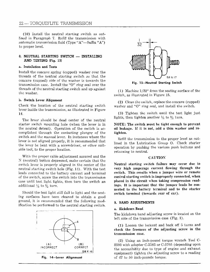
b. Switch Lever Alignment
Check the location of the neutra l s t a r t ing swi tch lever Inside the transmission, as i l lus t ra ted i n Figure 14.
The lever should be dead center of the neutral s tarter swi tch mount ing hole (when the lever Is i n the neutra l detent) . Operation o f the swi tch is accomplished th rough the contacting plunger of the swi tch and the manual lever. I n instances where the lever Is not aligned properly, i t is recommended tha t the lever be bent w i t h a screwdriver, or other suitable tool, to the proper location.
W i t h the proper cable adjustment assured and the N (neutral) bu t ton depressed, make certain tha t the switch lever is properly aligned i n the center of the neutral s t a r t ing switch hole ( F i g . 14) . W i t h the test leads connected to the bat tery current and te rmina l of the switch, screw the switch into the transmission case u n t i l test l i gh t l ights , then t u r n the switch an additional % to l / 2 t u r n .
Should the test l i g h t s t i l l f a i l to l i g h t and the seating surfaces have been cleaned to obtain a good ground, i t is recommended tha t the fo l lowing modification be performed to the neutral s t a r t ing switch.
INCORRECT CORRECT
5 8 X 16
Fig. 14—Lever Alignment
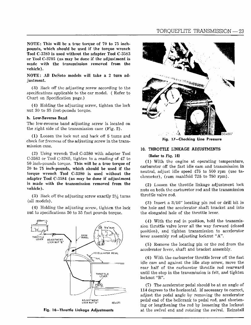
Fig. 15—Neutral Starting Switch
(1 ) Machine 1/32" f rom the seating surface of the switch, as I l lustrated i n Figure 15.
(2) Clean the switch, replace the concave (cupped) washer and " 0 " r i n g seal, and Install the switch.
(3 ) T igh ten the switch u n t i l the test l i g h t j u s t l ights , then t igh ten another % to l / 2 t u r n .
N O T E : The switch must be t i g h t enough to prevent o i l leakage. I f i t is not, add a t h i n washer and ret igh ten .
Refill the transmission to the proper level as outlined i n the Lubr ica t ion Group 0 . Check starter operation by pushing the various push buttons and re tu rn ing to neutral .
C A U T I O N
Neut ra l s t a r t ing swi tch fai lure may occur due to very h igh amperage current i o w l n g through the swi tch . This results when a jumper wi re or remote control s t a r t ing switch is improperly connected, when placed i n the ci rcui t when tak ing compression readings. I t Is Important tha t the jumper leads be connected to the bat tery te rmina l and to the starter swi tch te rmina l ( towards rear of ca r ) .
9. BAND ADIUSTMENTS
a. Kickdown Band
The kickdown band adjust ing screw is located on the lef t side of the transmission case (F ig . 1 ) .
(1 ) Loosen the locknut and back off 5 turns and check the freeness of the adjust ing screw In the transmission case.
(2) Us ing an inch-pound torque wrench Tool C-3380 w i t h adapter C-3583 or C-3705 (depending upon the accessibility due to type of engine and exhaust equipment) t igh ten the adjust ing screw to a reading of 47 to 50 inch-pounds torque.
T O R Q U E F L I T E T R A N S M I S S I O N — 23
N O T E : This w i l l be a t rue torque of 70 to 75 Inch-pounds, wh ich should be used I f the torque wrench Tool C-3380 Is used wi thou t the adapter Tool C-3583 or Tool C-3705 (as may be done I f the adjustment Is made w i t h the transmission removed f r o m the vehicle).
N O T E : A l l DeSoto models w i l l take a 2 t u r n adjus tment .
(3 ) Back off the adjust ing screw according to the specifications applicable to the car model. ( Refer to Chart on Specification page.)
(4 ) Hold ing the adjust ing screw, t i gh ten the lock nut 30 to 35 foot-pounds torque.
b. Low-Reverse Band The low-reverse band adjust ing screw is located on the r i g h t side of the transmission case ( F i g . 2).
(1) Loosen the lock nut and back off 5 turns and check for freeness of the adjust ing screw In the transmission case.
(2) Using wrench Tool .C-3380 w i t h adapter Tool C-3583 or Tool C-3705, t igh ten to a reading of 47 to 50 Inch-pounds torque. This w i l l be a t rue torque of 70 to 75 inch-pounds, which should be used i f the torque wrench Tool C-3380 is used w i t h o u t the adapter Tool C-3584 (as may be done I f adjustment Is made w i t h the transmission removed f rom the vehicle) .
(3 ) Back off the adjust ing screw exactly 214 turns (all models).
(4) Holding the adjust ing screw, t i g h t e n the lock nut to specifications 30 to 35 foot pounds torque.
ADJUSTMENT LOCK NUT "A" 60x171
Fig. 16—Throttle Linkage Adjustments
Fig. 17—Checking Line Pressure
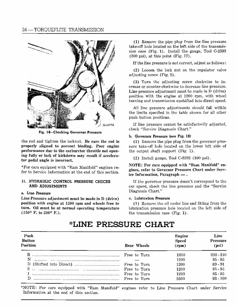
10. THROTTLE LINKAGE ADJUSTMENTS
(Refer to Fig. 16 ) (1 ) W i t h the engine at operating temperature,
carburetor off the fast Idle cam and transmission i n neutral , adjust idle speed 475 to 500 r p m (use tachometer) , ( r a m manifo ld 725 to 750 r p m ) .
(2) Loosen the t h ro t t l e l inkage adjustment lock nuts on bo th the carburetor rod and the transmission th ro t t l e valve rod.
(3 ) Inser t a 3/16" locating p in rod or d r i l l b i t i n the hole and the accelerator shaft bracket and into the elongated hole of the th ro t t l e lever.
(4 ) W i t h the rod i n posit ion, hold the transmission th ro t t l e valve lever al l the way f o r w a r d (closed posi t ion) , and t i gh ten transmission to accelerator lever assembly rod adjust ing locknut "A".
(5 ) Remove the locating p i n or the rod f r o m the accelerator lever, shaft and bracket assembly.
(6 ) W i t h the carburetor t h ro t t l e lever off the fast idle cam and against the idle stop screw, move the rear ha l f of the carburetor t h ro t t l e rod rearward u n t i l the stop i n the transmission is fel t , and t igh ten locknut HW\
(7) The accelerator pedal should be at an angle o f 114 degrees to the horizontal . I f necessary to correct, adjust the pedal angle by removing the accelerator pedal end of the bellcrank to pedal rod, and shorteni n g or lengthening the rod by loosening the locknut at the swivel end and ro ta t ing the swivel. Reinstall
24 — TORQUEFLITE TRANSMISSION
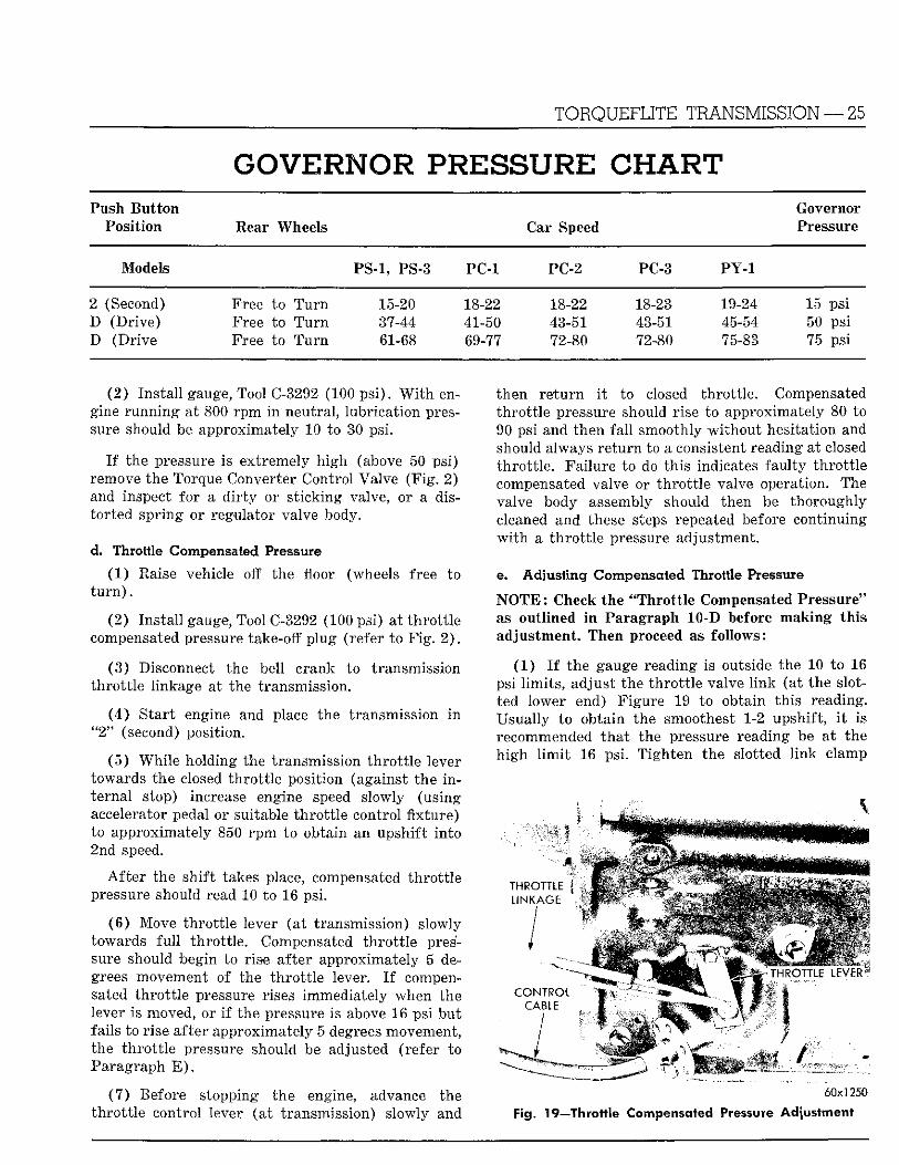
Fig. 18—Checking Governor Pressure
the rod and t igh ten the locknut. Be sure the rod is properly aligned to prevent binding. Poor engine performance due to the carburetor th ro t t l e not openi n g f u l l y or lack of k ickdown may result i f accelerato r pedal angle is incorrect.
*For cars equipped w i t h "Ram Mani fo ld" engines refer t o Service In fo rmat ion a t the end of this section.
11. H Y D R A U L I C CONTROL PRESSURE C H E C K S A N D ADJUSTMENTS
a. L ine Pressure
Line Pressure adjustment must be made i n D (d r ive ) posit ion w i t h engine at 1200 r p m and wheels free to t u r n . O i l must be at normal operat ing temperature ( 1 5 0 ° F . to 2 0 0 ° F . ) .
(1 ) Remove the pipe p lug f r o m the line pressure take-off hole located on the lef t side of the transmission case (F ig . 1 ) . Ins ta l l the gauge, Tool C-2393 (300 ps i ) , at th i s point (F ig . 17) .
I f the line pressure is not correct, adjust as fo l lows:
(2 ) Loosen the lock n u t on the regulator valve adjust ing screw (F ig . 2 ) .
(3 ) T u r n the adjust ing screw clockwise to i n crease or counter-clockwise to decrease line pressure. L i n e pressure adjustment must be made i n D (drive) position w i t h the engine at 1200 rpm, w i t h wheel t u r n i n g and transmission upshifted in to direct speed.
A l l line pressure adjustments should fa l l w i t h i n the l imi t s specified i n the table shown fo r al l other push bu t ton positions.
I f l ine pressure cannot be satisfactori ly adjusted, check "Service Diagnosis Chart ."
b. Governor Pressure (see F ig . 18)
(1 ) Remove the pipe p lug f rom the governor pressure take-off hole located on the lower left side of the output shaft support (F ig . 1 ) .
( 2 ) Ins ta l l gauge, Tool C-3292 (100 ps i ) .
N O T E : For cars equipped w i t h "Ram Mani fo ld" engines, refer to Governor Pressure Char t under Service In format ion , Paragraph — - .
I f the governor pressure doesn't correspond to the car speed, check the line pressure and the "Service Diagnosis Chart ."
c. Lubrication Pressure
(1 ) Remove the oil cooler line and fitting f r o m the lubr ica t ion pressure hole located on the left side of the transmission case (F ig . 1 ) .
*LINE P R E S S U R E CHART Push Engine Line
B u t t o n Speed Pressure Posit ion Rear Wheels ( r p m ) (psi)
R Free to T u r n 1600 200-240 N _ 1200 8 5 - 9 5 D (Shifted into Di rec t ) Free to T u r n 1200 89 - 91 2 - Free to T u r n 1200 8 5 - 9 5 1 Free • to T u r n 1200 8 5 - 9 5 D Free to T u r n 3500 93 - 100
N O T E : For cars equipped w i t h "Ram Ma n i fo l d " engines refer to Line Pressure Chart under Service In fo rma t ion at the end of th i s section.
TORQUEFLITE TRANSMISSION — 25
GOVERNOR PRESSURE CHART Push B u t t o n Governor
Position Rear Wheels Car Speed Pressure
Models PS-1, PS-3 PC-1 PC-2 PC-3 PY-1
2 (Second) Free to T u r n 15-20 18-22 18-22 18-23 19-24 15 psi D (Dr ive ) Free to T u r n 37-44 41-50 43-51 43-51 45-54 50 psi D (Dr ive Free to T u r n 61-68 69-77 72-80 72-80 75-83 75 psi
(2 ) Ins ta l l gauge, Tool C-3292 (100 ps i ) . W i t h engine runn ing at 800 r p m i n neutral , lubr icat ion pressure should be approximately 10 to 30 psi.
I f the pressure is extremely h igh (above 50 psi) remove the Torque Converter Control Valve (F ig . 2) and inspect for a d i r t y or s t icking valve, or a distor ted spr ing or regulator valve body.
d. Throttle Compensated Pressure
(1 ) Raise vehicle off the floor (wheels free to t u r n ) .
(2 ) Ins ta l l gauge, Tool C-3292 (100 psi) at th ro t t l e compensated pressure take-off p lug (refer to F ig . 2 ) .
(3 ) Disconnect the bell crank to transmission th ro t t l e l inkage at the transmission.
( 4 ) S tar t engine and place the transmission i n " 2 " (second) position.
(5 ) Whi l e holding the transmission t h r o t t l e lever towards the closed th ro t t l e position (against the i n ternal stop) increase engine speed slowly (using accelerator pedal or suitable th ro t t l e control fixture) to approximately 850 r p m to obtain an upshif t in to 2nd speed.
A f t e r the shi f t takes place, compensated th ro t t l e pressure should read 10 to 16 psi.
(6 ) Move th ro t t l e lever (at transmission) slowly towards f u l l th ro t t l e . Compensated t h ro t t l e pressure should begin to rise af ter approximately 5 degrees movement of the t h ro t t l e lever. I f compensated th ro t t l e pressure rises immediately when the lever is moved, or i f the pressure is above 16 psi bu t fails to rise after approximately 5 degrees movement, the t h ro t t l e pressure should be adjusted (refer to Paragraph E ) .
(7 ) Before stopping the engine, advance the t h ro t t l e control lever (a t transmission) slowly and
then r e t u r n i t to closed th ro t t l e . Compensated th ro t t l e pressure should rise to approximately 80 to 90 psi and then fa l l smoothly w i t h o u t hesitation and should always r e tu rn to a consistent reading at closed th ro t t l e . Fai lure to do th is indicates fau l ty t h ro t t l e compensated valve or t h ro t t l e valve operation. The valve body assembly should then be thoroughly cleaned and these steps repeated before continuing w i t h a t h ro t t l e pressure adjustment.
e. Adjusting Compensated Throttle Pressure
N O T E : Check the "Thro t t l e Compensated Pressure" as outl ined i n Paragraph 10-D before mak ing th is adjustment. Then proceed as fol lows:
( 1 ) I f the gauge reading is outside the 10 to 16 psi l imi t s , adjust the t h ro t t l e valve l i nk (at the slotted lower end) Figure 19 to obtain th is reading. Usual ly to obtain the smoothest 1-2 upshift , i t is recommended tha t the pressure reading be at the h i g h l i m i t 16 psi. T igh ten the slotted l i n k clamp
T H R O T T L E ^ ^ ^ ^ ^ ^ ^ ^ ^ ^ ^ ^ ^ ^ ^ ^ ^ ^ ^ ^ ^ ^ ^ ^ M L I N K A G E ! •
, J M B S B E B I THROTTLE LEVER
C O N T R O L ' i^ ^ ^ ^ ^ ^ ^ ^ ^ ^ ^ ^ ^ ^ ^ ^ ^ ^ ^ ^ ^ ^ S ^ W C A B L E MgB^ j^-rr^ " •; • \ Wm^
60x1250
Fig. If—Throttle Compensated Pressure Adjustment
26 — TORQUEFLITE TRANSMISSION
bolt . The transmission th ro t t l e l inkage adjustment is now correct, however, fo r a iding i n fu ture adjustments, i t is recommended tha t the t h ro t t l e valve stop screw be correctly set.
(2 ) Push i n the " N " Neu t ra l bu t ton . Block the carburetor choke i n the open position.
(3 ) Dra in the transmission fluid. Remove the
transmission oil pan.
(4) Adjus t the transmission th ro t t l e valve stop screw so tha t the end of the stop screw j u s t contacts the th ro t t l e lever w i t h the accelerator pedal released. T igh ten the stop screw lock nut .
(5 ) Ins ta l l the transmission oil pan using a new gasket. Refill the transmission to proper fluid level.
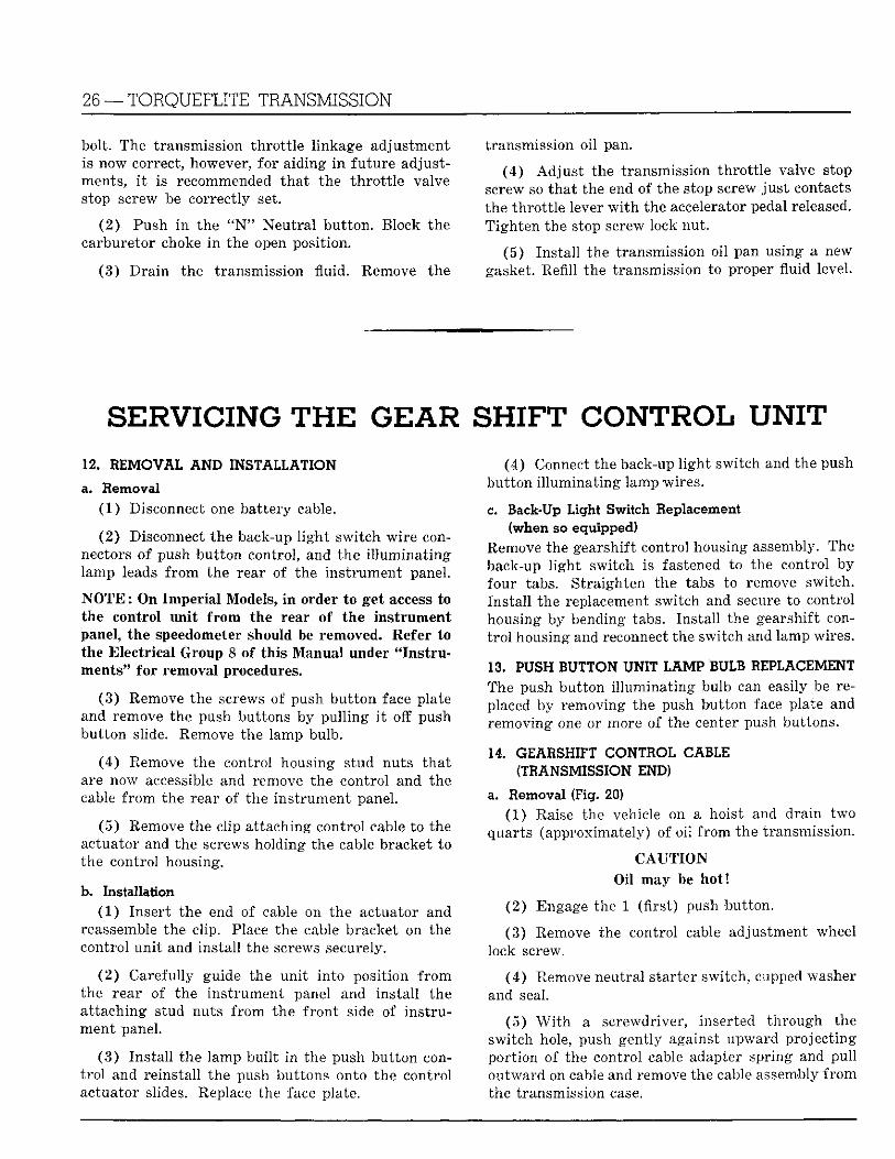
SERVICING T H E GEAR SHIFT CONTROL UNIT 12. REMOVAL AND INSTALLATION
a. Removal (1) Disconnect one bat tery cable.
(2 ) Disconnect the back-up l i g h t swi tch wi re connectors of push bu t ton control, and the i l l umina t ing lamp leads f r o m the rear of the ins t rument panel.
N O T E : On Imperial Models, in order to get access to the control unit from the rear of the instrument panel, the speedometer should be removed. Refer to the Electrical Group 8 of this Manual under "Instruments" for removal procedures.
(3 ) Remove the screws of push bu t t on face plate and remove the push buttons by pu l l ing i t off push but ton slide. Remove the lamp bulb.
(4 ) Remove the control housing stud nuts tha t are now accessible and remove the control and the cable f r o m the rear of the ins t rument panel.
(5 ) Remove the clip at taching control cable to the actuator and the screws holding the cable bracket to the control housing.
b. Installation (1) Inser t the end o f cable on the actuator and
reassemble the clip. Place the cable bracket on the control un i t and ins ta l l the screws securely.
(2) Carefully guide the un i t in to posi t ion f r o m the rear of the ins t rument panel and ins ta l l the a t taching stud nuts f r o m the f ron t side of ins t ru ment panel.
( 3 ) Ins ta l l the lamp bui l t i n the push bu t ton cont r o l and reinstal l the push buttons onto the control actuator slides. Replace the face plate.
(4) Connect the back-up l i gh t switch and the push but ton i l lumina t ing lamp wires.
c. Back-Up Light Switch Replacement (when so equipped)
Remove the gearshift control housing assembly. The back-up l i gh t switch is fastened to the control by four tabs. Straighten the tabs to remove switch. Ins ta l l the replacement switch and secure to control housing by bending tabs. Ins ta l l the gearshift cont r o l housing and reconnect the switch and lamp wires.
13. PUSH BUTTON UNIT LAMP "BULB REPLACEMENT The push but ton i l lumina t ing bulb can easily be replaced by removing the push bu t ton face plate and removing one or more of the center push buttons.
14. GEARSHIFT CONTROL CABLE (TRANSMISSION END)
a. Removal (Fig. 20) (1) Raise the vehicle on a hoist and drain two
quarts (approximately) of oi l f r o m the transmission.
C A U T I O N Oil may be hot!
(2 ) Engage the 1 (f i rs t) push but ton.
(3) Remove the control cable adjustment wheel lock screw.
(4 ) Remove neutral s tarter switch, cupped washer and seal.
(5 ) W i t h a screwdriver, inserted th rough the swi tch hole, push gently against upward project ing por t ion of the control cable adapter spring and pul l ou tward on cable and remove the cable assembly f r o m the transmission case.
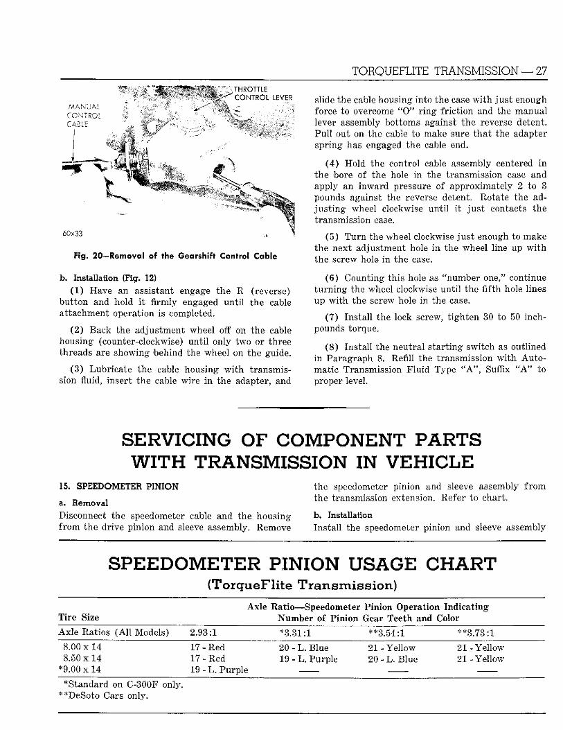
TORQUEFLITE TRANSMISSION — 27 ^ ^ ^ ^ ^ ^ ^ ^ ^ ^ ^ ^ M THROTTLE
CONTROL LEVER A A A M I t A i i^^if^^KS^fiBHHHr " v i^HHHk'- it.;" ^ 'li^^^Kl^^^H M A N U A L M^lf^^^HHHBS^Li xSi^iHBBBk'-'4€^:; J ^^W^^^^^^B CONTROL CABLE
^ ^ ^ ^
6 0 x 3 3
Fig. 20—Removal of the Gearshift Control Cable
b. Installation (Fig. 12) (1 ) Have an assistant engage the R (reverse)
but ton and hold i t f i r m l y engaged u n t i l the cable at tachment operation is completed.
(2 ) Back the adjustment wheel off on the cable housing (counter-clockwise) u n t i l only two or three threads are showing behind the wheel on the guide.
(3 ) Lubr ica te the cable housing w i t h transmission fluid, insert t he cable wire i n the adapter, and
slide the cable housing into the case w i t h j u s t enough force to overcome " 0 " r i n g f r i c t i on and the manual lever assembly bottoms against the reverse detent. Pu l l out on the cable to make sure t ha t the adapter spr ing has engaged the cable end.
(4 ) Ho ld the control cable assembly centered i n the bore o f the hole i n the transmission case and apply an inward pressure of approximately 2 to 3 pounds against the reverse detent. Rotate the adj u s t i n g wheel clockwise u n t i l i t j u s t contacts the transmission case.
(5 ) T u r n the wheel clockwise j u s t enough to make the next adjustment hole i n the wheel line up w i t h the screw hole i n the case.
(8 ) Counting this hole as "number one," continue t u r n i n g the wheel clockwise u n t i l the f i f t h hole lines up w i t h the screw hole i n the case.
(7) Ins ta l l the lock screw, t igh ten 30 to 50 inch-pounds torque.
(8 ) Ins ta l l the neutra l s ta r t ing swi tch as outlined i n Paragraph 8. Refill the transmission w i t h A u t o mat ic Transmission F l u i d Type " A " , Suffix " A " to proper level.
SERVICING OF COMPONENT PARTS WITH TRANSMISSION IN V E H I C L E
15. SPEEDOMETER PINION
a. Removal Disconnect the speedometer cable and the housing f r o m the drive pinion and sleeve assembly. Remove
the speedometer pinion and sleeve assembly f r o m the transmission extension. Refer to chart.
b. Installation Ins ta l l the speedometer pinion and sleeve assembly
SPEEDOMETER PINION USAGE CHART (TorqueFlite Transmission)
Axle Ratio—Speedometer Pinion Operation Ind ica t ing Ti re Size ^ Number of Pinion Gear Teeth and Color
Axle Ratios ( A l l Models) 2.93:1 *3.31:1 **3.54:1 **3.73:1
8.00 x 14 ^ 17 - Red 20 - L. Blue 21 - Yellow 2 1 - Y e l l o w 8.50 x 14 17 - Red 19 - L. Purple 20 - L . Blue 21 - Yellow
* 9 . 0 0 x l 4 19 - L . Purple — —
•Standard on C-300F only. ^ ^ **DeSoto Cars only.
28 — TORQUEFLITE TRANSMISSION
In the transmission extension and t igh ten 40 to 45 foot-pounds torque.
16. NEUTRAL STARTING SWITCH
a. Removal Dra in approximately three quarts of fluid f rom the transmission by disconnecting filler tube at o i l pan connector (may be necessary to loosen the filler tube support bracket screw). Remove wire at switch the remove switch.
b. Installation Refer to Paragraph 8.
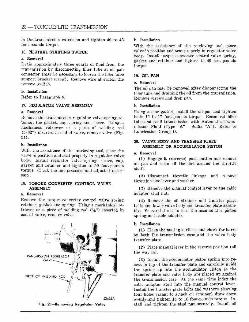
17. REGULATOR V A L V E ASSEMBLY
a. Removal Remove the transmission regulator valve spring retainer, the gasket, cup, spring and sleeve. Using a mechanical retr iever or a piece of welding rod (5/32") inserted in end of valve, remove valve ( F i g . 21) .
b. Installation W i t h the assistance of the re t r i ev ing tool, place the valve i n position and seat properly i n regulator valve body. Ins ta l l regulator valve spring, sleeve, cup, gasket and retainer and t igh ten to 50 foot-pounds torque. Check the line pressure and adjust i f necessary.
18. TORQUE CONVERTER CONTROL VALVE ASSEMBLY
a. Removal Remove the torque converter control valve spr ing retainer, gasket and spring. Us ing a mechanical ret r iever or a piece of welding rod ( % " ) inserted i n end of valve, remove valve.
TRANSMISSION KFGUi A ' .> V A I V E - ^ ^
PIECE OF WELDING RO» > • *f.
53x55 A
Fig. 21—Removing Regulator Va lve
b. Installation W i t h the assistance of the re t r i ev ing tool, place valve i n position and seat properly i n regulator valve body. Ins ta l l torque converter control valve spring, gasket and retainer and t igh ten to 40 foot-pounds torque.
19. OIL PAN
a. Removal The oil pan may be removed after disconnecting the filler tube and dra in ing the oil f rom the transmission. Remove screws and drop pan.
b. Installation Using a new gasket, ins ta l l the oi l pan and t igh ten bolts 12 to 17 foot-pounds torque. Reconnect filler tube and refi l l transmission w i t h Automat ic Transmission F lu id (Type " A " — Suffix " A " ) . Refer to Lubr ica t ion Group D.
20. V A L V E BODY AND TRANSFER PLATE ASSEMBLY OR ACCUMULATOR PISTON
a. Removal (1) Engage R (reverse) push bu t ton and remove
oi l pan and clean off the d i r t around the th ro t t l e shaft.
(2 ) Disconnect t h ro t t l e linkage and remove th ro t t l e valve lever and washer.
(3 ) Remove the manual control lever to the cable adapter stud nut .
( 4 ) Remove the oil strainer and transfer plate bolts and lower valve body and transfer plate assembly . Be careful not to lose the accumulator piston spr ing and cable adapter.
b. Installation (1) Clean the mat ing surfaces and check fo r burrs
on both the transmission case and the valve body t ransfer plate.
(2 ) Place manual lever i n the reverse position (all the way i n ) .
( 3 ) Ins ta l l the accumulator piston spr ing in to recess i n top of the transfer plate and carefully guide the spr ing up into the accumulator piston as the t ransfer plate and valve body are placed up against the transmission case. A t the same t ime index the cable adapter stud into the manual control lever. Ins ta l l the transfer plate bolts and washers (leaving four holes vacant to at tach oi l s t rainer) draw down evenly and t igh ten 14 to 16 foot-pounds torque. I n s ta l l and t igh ten the stud nu t securely. Ins ta l l oi l

T O R Q U E F L I T E T R A N S M I S S I O N — 29
strainer and t igh ten the remaining bolts 14 to 16 foot-pounds torque.
(4 ) Ins ta l l the th ro t t l e valve lever and washer and reconnect the t h ro t t l e linkage.
( 5 ) Ins ta l l oi l pan and refil l the transmission w i t h Automat ic Transmission F l u i d (Type " A " — Suffix " A " ) to proper level.
(6 ) Ad jus t the th ro t t l e linkage.
21. I I C 1 D O W N PISTON
a. Removal (1 ) Remove oil pan and valve body assembly.
(2 ) Loosen the kickdown band adjust ing screw lock nu t and back out screw sufficiently to remove anchor and s t ru t .
(3 ) Ins ta l l compressing Tool C-3529 or C-3289 (modified), apply sufficient pressure on kickdown piston rod guide and remove snap r i ng .
(4 ) Remove tool, piston rod guide, piston spr ing and rod. Using C-484 pliers, remove the k ickdown piston f r o m transmission case (F ig . 22) . Refer to Kickdown Piston Inspection, Paragraph 82.
b. Installation (1 ) Lubricate the piston seal r ings and place pis
ton i n position, compress outer r i n g and s tar t assembly in to case. W i t h the piston properly centered so as not to damage rings, tap l i g h t l y u n t i l piston bottoms i n case.
(2 ) Place the kickdown piston rod assembly in piston and slide piston spring over k ickdown piston rod.
(3 ) Ins ta l l Tool C-3529 or C-3289 (Modified) on
T O O L
• - 4-'
57x98
Fig. 23—Removing Handbrake Drum and Flange Assembly
case and place kickdown piston rod guide over spring, compress spr ing and instal l snap r ing . Remove compressing tool.
(4 ) Place the k ickdown band s t ru t in to position i n the band and lever and compress band end sufficiently to insta l l the anchor over the adjust ing screw.
(5 ) Ad jus t k ickdown band as outlined under "Maintenance, Adjus tments and Tests," Paragraph 9 A ) .
(6 ) Ins ta l l valve body assembly and oi l pan.
22. OUTPUT SHAFT REAR OIL SEAL
a. Removal (1 ) Disconnect the f ron t universal j o in t .
( 2 ) Apply pa rk ing brake or use wrench Tool C-3281 (F ig . 23) and remove flange nut. Release the pa rk ing brake ( i f applied) and remove the park ing brake flange and d r u m assembly. Use puller Tool C-452, i f necessary.
T O C
-4
" J C K D O W N • W O P I S T O N
" O O L
^ T O O L
REAR E X T E N S I O N
" * ..C6x661 A Fig. 22—Removal and Installation of Kickdown Piston
60x30
Fig. 24—Removing Output Shaft Rear Bearing Oil Seal
30 — TORQUEFLITE TRANSMISSION
(3) Remove the brake support grease shield spr ing and grease shield.
(4) I f screwdriver or sharp ins t rument is used i n per forming th is operation, care must be exercised not to damage the neoprene sealing surface at bott o m of the shield.
Ins ta l l puller, Tool C-3690 and remove the transmission output shaft rear bushing oil seal (F ig . 24) .
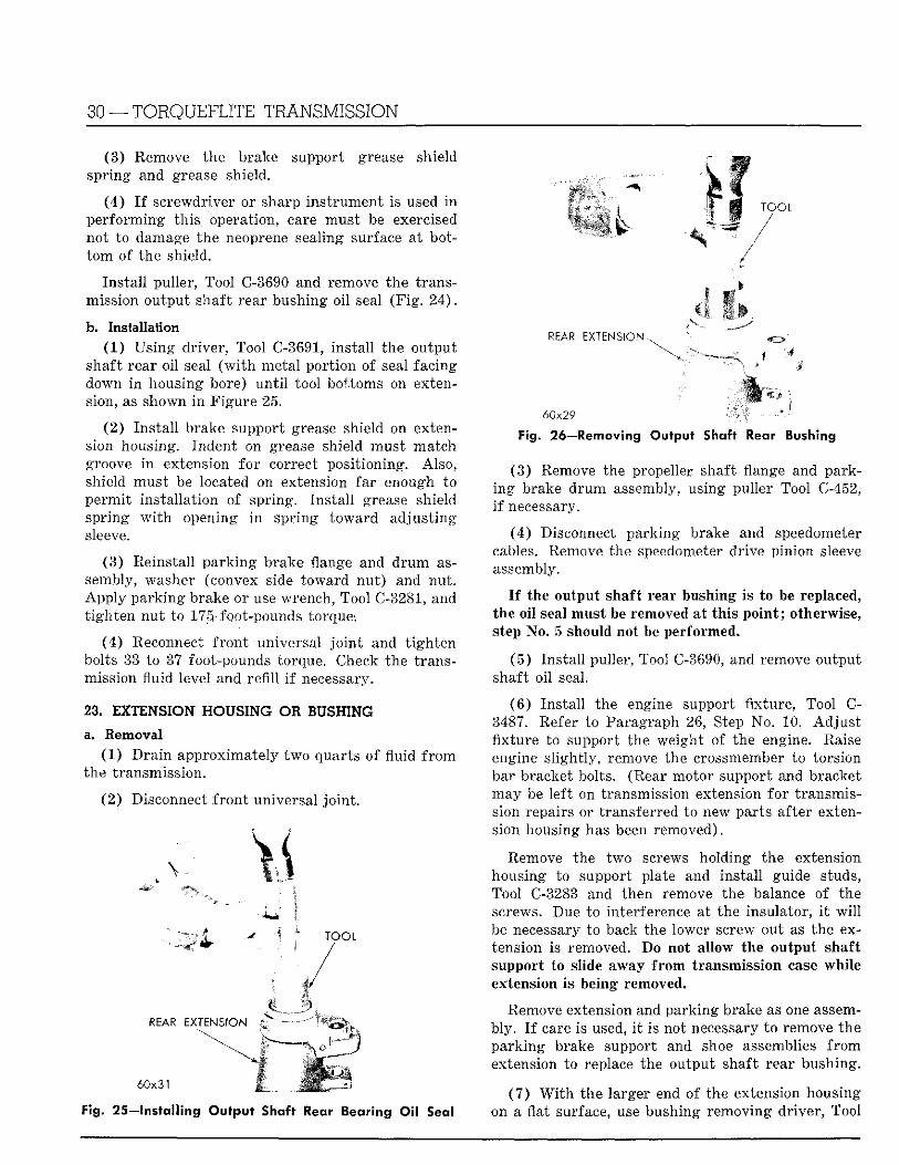
b. Installation (1) Us ing dr iver , Tool C-3691, ins ta l l the output
shaft rear oi l seal ( w i t h metal por t ion of seal facing down i n housing bore) u n t i l tool bottoms on extension, as shown i n Figure 25.
(2) Ins ta l l brake support grease shield on extension housing. Indent on grease shield must match groove i n extension fo r correct posit ioning. Also, shield must be located on extension far enough to permi t instal lat ion of spring. Ins ta l l grease shield spring w i t h opening i n spr ing toward adjust ing sleeve.
(3) Reinstall pa rk ing brake flange and d r u m assembly, washer (convex side toward nu t ) and nut . App ly pa rk ing brake or use wrench, Tool C-3281, and t igh ten nu t to 175. foot-pounds torque-.
(4) Reconnect f ron t universal j o i n t and t igh ten bolts 33 to 37 foot-pounds torque. Check the transmission fluid level and refi l l i f necessary.
23. EXTENSION HOUSING OR BUSHING ..
a. Removal (1) D r a i n approximately two quarts of fluid f r o m
the transmission.
(2 ) Disconnect f ron t universal j o in t .
St "
REAR EXTENSION
60x31
Fig. 25—Installing Output Shaft Rear Bearing Oil Seal
REAR E X T E N S I O N ^
6 0 x 2 9
Fig. 26—Removing Output Shaft Rear Bushing
(3) Remove the propeller shaft flange and parking brake d r u m assembly, using puller Tool C-452, i f necessary.
(4) Disconnect park ing brake and speedometer cables. Remove the speedometer drive pinion sleeve assembly.
I f the output shaft rear bushing is to be replaced, the oi l seal must be removed at th is po in t ; otherwise, step No. 5 should not be performed.
(5 ) Ins ta l l puller, Tool C-3690, and remove output shaft oi l seal.
(6 ) Ins ta l l the engine support fixture, Tool C-3487. Refer to Paragraph 26, Step No. 10. Ad jus t fixture to support the weight of the engine. Raise engine s l ight ly , remove the crossmember to torsion bar bracket bolts. (Rear motor support and bracket may be lef t on transmission extension for transmission repairs or transferred to new parts after extension housing has been removed).
Remove the two screws holding the extension housing to support plate and instal l guide studs, Tool C-3283 and then remove the balance of the screws. Due to interference at the insulator, i t w i l l be necessary to back the lower screw out as the extension is removed. Do not allow the output shaft support to slide away f r o m transmission case whi le extension is being removed.
Remove extension and park ing brake as one assembly. I f care is used, i t is not necessary to remove the pa rk ing brake support and shoe assemblies f r o m extension to replace the output shaft rear bushing.
(7 ) W i t h the larger end of the extension housing on a flat surface, use bushing removing dr iver , Tool
TORQUEFLITE TRANSMISSION —31
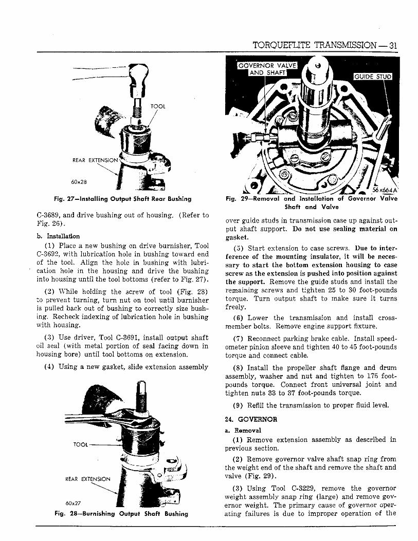
Fig, 27—Installing Output Shaft Rear Bushing
C-3689, and dr ive bushing out of housing. (Refer to F i g . 26) .
b. Installation (1) Place a new bushing on drive burnisher, Tool
C-3692, w i t h lubricat ion hole in bushing toward end of the tool. A l i g n the hole i n bushing w i t h l u b r i cation hole i n the housing and drive the bushing into housing un t i l the tool bottoms (refer to F ig . 27) .
(2) Whi le holding the screw of tool (F ig . 28) to prevent tu rn ing , t u r n nut on tool u n t i l burnisher is pulled back out of bushing to correctly size bushing. Recheck indexing of lubricat ion hole in bushing w i t h housing.
(3) Use driver, Tool C-3691, instal l output shaft oil seal ( w i t h metal por t ion of seal facing down i n housing bore) u n t i l tool bottoms on extension.
(4) Using a new gasket, slide extension assembly
Fig. 28—Burnishing Output Shaft Bushing
Fig. 29—Removal and Installation of Governor Valve Shaft and Valve
over guide studs i n transmission case up against output shaft support. Do not use sealing mater ia l on gasket.
(5) S tar t extension to case screws. Due to interference of the mount ing insulator, i t w i l l be necessary to s ta r t the bot tom extension housing to case screw as the extension is pushed into position against the support. Remove the guide studs and install the remaining screws and t igh ten 25 to 30 foot-pounds torque. T u r n output shaft to make sure i t turns freely.
(6) Lower the transmission and instal l cross-member bolts. Remove engine support f ixture.
(7 ) Reconnect pa rk ing brake cable. Ins ta l l speedometer pinion sleeve and t igh ten 40 to 45 foot-pounds torque and connect cable.
(8) Ins ta l l the propeller shaft flange and d rum assembly, washer and nut and t igh ten to 175 footpounds torque. Connect f ront universal j o i n t and t ighten nuts 33 to 37 foot-pounds torque.
(9) Refill the transmission to proper fluid level.
24. GOVERNOR
a. Removal (1) Remove extension assembly as described i n
previous section.
(2) Remove governor valve shaft snap r i n g f r o m the weight end of the shaft and remove the shaft and valve (F ig . 29 ) .
(3) Us ing Tool C-3229, remove the governor weight assembly snap r i n g (large) and remove governor weight . The p r imary cause of governor opera t ing failures is due to improper operation of the
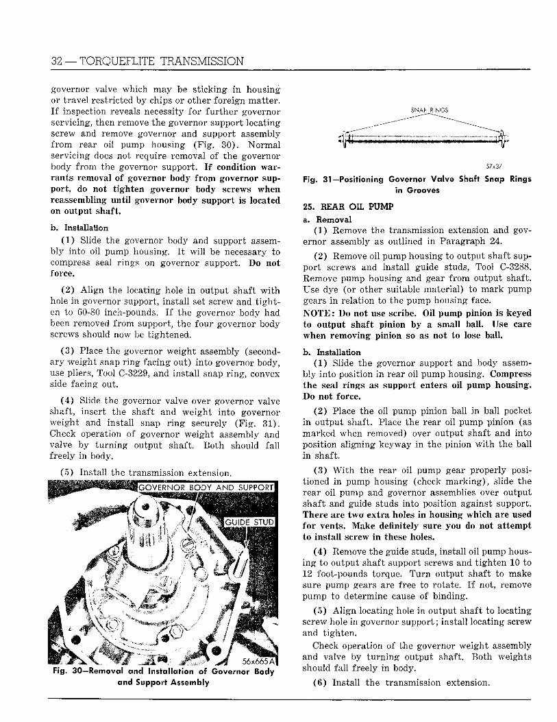
32 — T O R Q U E F L I T E T R A N S M I S S I O N
governor valve which may be s t ick ing i n housing or t ravel restricted by chips or other foreign matter . I f inspection reveals necessity fo r fu r the r governor servicing, then remove the governor support locating screw and remove governor and support assembly f r o m rear oil pump housing (F ig . 30) . Norma l servicing does not require removal of the governor body f rom the governor support. I f condition warrants removal of governor body f r o m governor support , do not t igh ten governor body screws when reassembling u n t i l governor body support is located on output shaft.
b. Installation (1 ) Slide the governor body and support assem
bly into oil pump housing. I t w i l l be necessary to compress seal r ings on governor support. Do not force.
(2 ) A l i g n the locating hole i n output shaft w i t h hole i n governor support, ins ta l l set screw and t i g h t en to 60-80 inch-pounds. I f the governor body had been removed f rom support, the four governor body screws should now be t ightened.
(3 ) Place the governor weight assembly (secondary weight snap r i n g facing out) in to governor body, use pliers, Tool C-3229, and ins ta l l snap r ing , convex side facing out.
(4 ) Slide the governor valve over governor valve shaft, insert the shaft and weigh t in to governor weight and instal l snap r i n g securely (F ig . 31) . Check operation of governor weight assembly and valve by t u r n i n g output shaft. Bo th should f a l l freely i n body.
(5) Ins ta l l the transmission extension.
Fig. 30—Removal and installation of Governor Body and Support Assembly
SNAP RINGS
57x37
Fig. 31—Positioning Governor Valve Shaft Snap Rings in Grooves
25. BEAR OIL PUMP a. Removal
(1 ) Remove the transmission extension and governor assembly as outlined i n Paragraph 24.
(2) Remove oil pump housing to output shaft suppor t screws and instal l guide studs, Tool C-3288. Remove pump housing and gear f r o m output shaft. Use dye (or other suitable material) to mark pump gears i n relat ion to the pump housing face. N O T E : Do not use scribe. Oi l pump pinion is keyed to output shaft pinion by a small ball. Use care when removing pinion so as not to lose ball .
b. Installation (1 ) Slide the governor support and body assem
bly in to position i n rear oi l pump housing. Compress the seal r ings as support enters o i l pump housing. Do not force.
(2 ) Place the oil pump pinion ball i n ball pocket i n output shaft. Place the rear oi l pump pinion (as marked when removed) over output shaft and into position al igning keyway i n the pinion w i t h the ball i n shaft.
(3 ) W i t h the rear oil pump gear properly positioned i n pump housing (check m a r k i n g ) , slide the rear oi l pump and governor assemblies over output shaft and guide studs into position against support. There are two extra holes i n housing which are used for vents. Make definitely sure you do not a t tempt to ins ta l l screw i n these holes.
(4 ) Remove the guide studs, ins ta l l oi l pump housi n g to output shaft support screws and t igh ten 10 to 12 foot-pounds torque. T u r n output shaft to make sure pump gears are free to rotate. I f not, remove pump to determine cause of binding.
( 5 ) A l i g n locating hole i n output shaft to locating screw hole i n governor support; instal l locating screw and t igh ten .
Check operation of the governor weight assembly and valve by t u r n i n g output shaft. Bo th weights should fa l l freely i n body.
( 6 ) Ins ta l l the transmission extension.
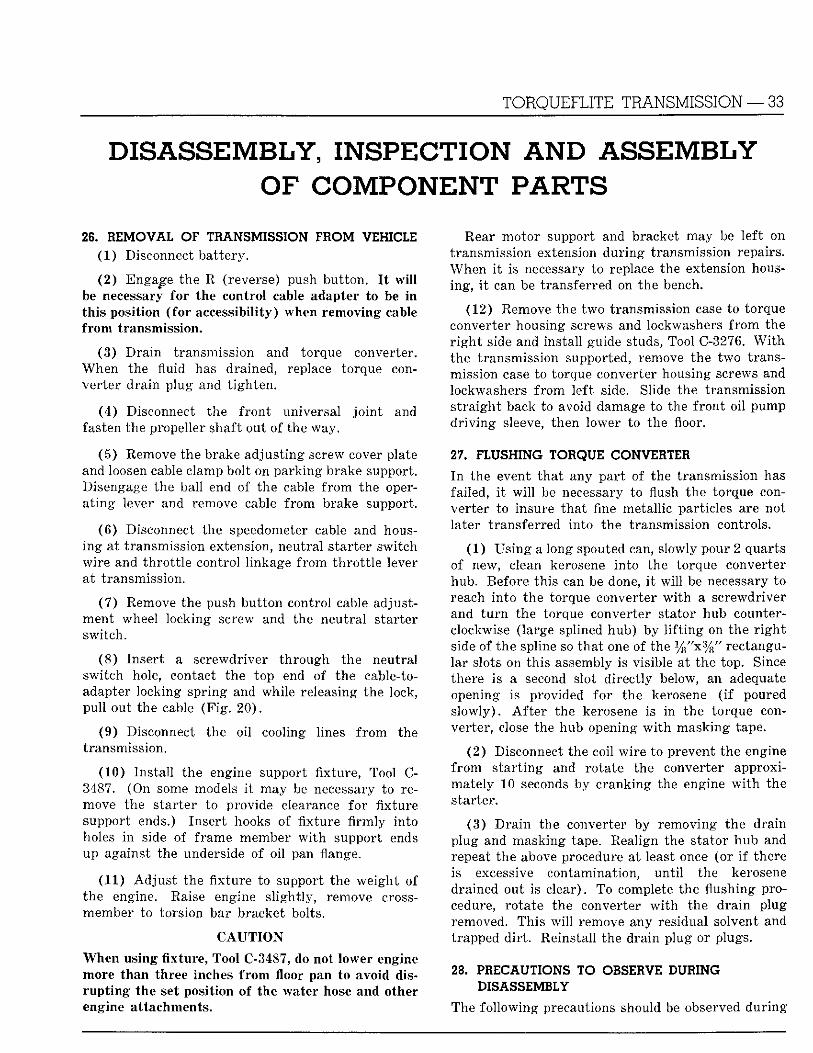
TORQUEFLITE TRANSMISSION — 33
DISASSEMBLY, INSPECTION AND ASSEMBLY OF COMPONENT PARTS
26. REMOVAL O F TRANSMISSION FROM VEHICLE (1) Disconnect bat tery.
(2) Engage the R (reverse) push but ton . I t w i l l be necessary for the control cable adapter to be i n th is position ( fo r accessibility) when removing cable f rom transmission.
(3) Dra in transmission and torque converter. When the fluid has drained, replace torque converter dra in plug and t igh ten .
(4) Disconnect the f ron t universal j o i n t and fasten the propeller shaft out of the way.
(5) Remove the brake adjust ing screw cover plate and loosen cable clamp bolt on park ing brake support. Disengage the ball end of the cable f r o m the opera t ing lever and remove cable f rom brake support.
(6) Disconnect the speedometer cable and housing at transmission extension, neutral s tarter switch wi re and th ro t t l e control linkage f rom th ro t t l e lever at transmission.
(7 ) Remove the push bu t ton control cable adjustment wheel locking screw and the neutral starter switch.
(8 ) Inser t a screwdriver th rough the neutral switch hole, contact the top end of the cable-to-adapter locking spr ing and while releasing the lock, pu l l out the cable (F ig . 20) .
(9) Disconnect the oi l cooling lines f r o m the transmission.
(10) Ins ta l l the engine support fixture, Tool C-3487. (On some models i t may be necessary to remove the starter to provide clearance for fixture support ends.) Insert hooks of fixture firmly into holes i n side of frame member w i t h support ends up against the underside of oi l pan flange.
(11) Ad jus t the fixture to support the weight of the engine. Raise engine s l ight ly , remove cross-member to torsion bar bracket bolts.
C A U T I O N
When using fixture, Tool C-3487, do not lower engine more than three inches f r o m floor pan to avoid disr u p t i n g the set position of the water hose and other engine attachments.
Rear motor support and bracket may be lef t on transmission extension dur ing transmission repairs. When i t is necessary to replace the extension housing, i t can be transferred on the bench.
(12) Remove the two transmission case to torque converter housing screws and lockwashers f r o m the r i g h t side and instal l guide studs, Tool C-3276. W i t h the transmission supported, remove the two transmission case to torque converter housing screws and lockwashers f r o m left side. Slide the transmission s t ra ight back to avoid damage to the f ron t oil pump d r i v i n g sleeve, then lower to the floor.
27. FLUSHING TORQUE CONVERTER
I n the event tha t any par t of the transmission has failed, i t w i l l be necessary to flush the torque converter to insure tha t fine metallic particles are not later t ransferred into the transmission controls.
(1 ) Us ing a long spouted can, slowly pour 2 quarts of new, clean kerosene in to the torque converter hub. Before th is can be done, i t w i l l be necessary to reach in to the torque converter w i t h a screwdriver and t u r n the torque converter stator hub counterclockwise (large splined hub) by l i f t i n g on the r i g h t side of the spline so tha t one of the % " x % / / rectangular slots on th is assembly is visible at the top. Since there is a second slot direct ly below, an adequate opening is provided for the kerosene ( i f poured s lowly) . A f t e r the kerosene is in the torque converter, close the hub opening w i t h masking tape.
(2 ) Disconnect the coil w i re to prevent the engine f r o m s t a r t ing and rotate the converter approximately 10 seconds by cranking the engine w i t h the starter.
(3) D r a i n the converter by removing the drain plug and masking tape. Realign the stator hub and repeat the above procedure at least once (or i f there is excessive contamination, un t i l the kerosene drained out is clear). To complete the flushing procedure, rotate the converter w i t h the d ra in plug removed. This w i l l remove any residual solvent and trapped d i r t . Reinstall the dra in plug or plugs.
28. PRECAUTIONS TO OBSERVE DURING DISASSEMBLY
The fo l lowing precautions should be observed dur ing
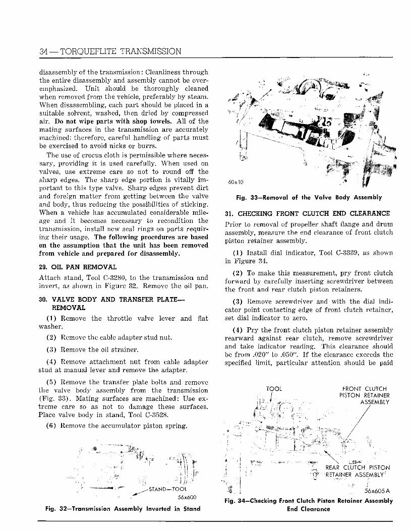
34 —TORQUEFLITE TRANSMISSION
disassembly of the transmission: Cleanliness t h rough the entire disassembly and assembly cannot be overemphasized. U n i t should be thoroughly cleaned when removed f r o m the vehicle, preferably by steam. When disassembling, each par t should be placed i n a suitable solvent, washed, then dried by compressed air. Do not wipe parts w i t h shop towels. A l l of the ma t ing surfaces i n the transmission are accurately machined; therefore, careful handling of parts must be exercised to avoid nicks or burrs .
The use o f crocus cloth is permissible where necessary, provid ing i t is used carefully. When used on valves, use extreme care so not to round off the sharp edges. The sharp edge por t ion is v i t a l l y i m portant to this type valve. Sharp edges prevent d i r t and foreign mat te r f r o m ge t t ing between the valve and body, thus reducing the possibilities of s t icking. When a vehicle has accumulated considerable mileage and i t becomes necessary to recondit ion the transmission, ins ta l l new seal r ings on parts requiring the i r usage. The fo l lowing procedures are based on the assumption tha t the un i t has been removed f r o m vehicle and prepared fo r disassembly.
29. OIL PAN REMOVAL
A t t a c h stand, Tool C-3280, to the transmission and invert , as shown i n Figure 32. Remove the oi l pan.
30. VALVE BODY AND TRANSFER PLATE— REMOVAL
(1) Remove the th ro t t l e valve lever and flat washer.
(2) Remove the cable adapter stud nut .
(3 ) Remove the oi l strainer.
(4) Remove at tachment nu t f rom cable adapter stud at manual lever and remove the adapter.
(5 ) Remove the transfer plate bolts and remove the valve body assembly f r o m the transmission (F ig . 33) . M a t i n g surfaces are machined: Use extreme care so as not to damage these surfaces. Place valve body i n stand, Tool C-3528.
(6 ) Remove the accumulator piston spring.
4 M WfWm
mm
6 0 x 1 0
Fig. 33—Removal of the Valve Body Assembly
31. CHECKING FRONT CLUTCH END CLEARANCE
Prior to removal of propeller shaft flange and d r u m assembly, measure the end clearance of f ron t clutch piston retainer assembly.
(1) Ins ta l l dial indicator, Tool C-3339, as shown i n Figure 34.
(2 ) To make this measurement, p ry f ron t clutch fo rward by carefully inser t ing screwdriver between the f ron t and rear clutch piston retainers.
(3) Remove screwdriver and w i t h the dial ind i cator point contacting edge of f ront clutch retainer, set dial indicator to zero.
(4 ) P r y the f ron t clutch piston retainer assembly rearward against rear clutch, remove screwdriver and take indicator reading. This clearance should be f r o m .020" to .050". I f the clearance exceeds the specified l i m i t , par t icular a t tent ion should be paid
F O O L
I (:mi
FRONT CLUTCH PISTON RETAINER
ASSEMBLY
REAR CLUTCH P I S T O N RETAINER ASSEMBLY'
- S T A N D - T O O L 56x600
Fig. 32—Transmission Assembly Inverted in Stand
\ 1 • . 56x605 A
Fig. 34—Checking Front Clutch Piston Retainer Assembly
End Clearance
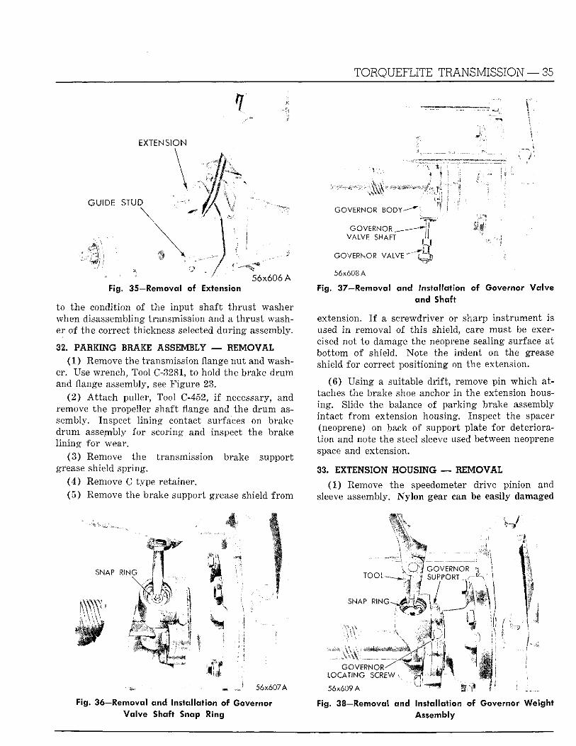
TORQUEFLITE TRANSMISSION — 35
EXTENS ION
• ; " ••' 56x606 A Fig. 35—Removal of Extension
to the condition of the input shaft t h rus t washer when disassembling transmission and a th rus t washer of the correct thickness selected dur ing assembly.
32. PARKING BRAKE ASSEMBLY — REMOVAL (1) Remove the transmission flange nu t and wash
er. Use wrench, Tool C-3281, to hold the brake d r u m and flange assembly, see Figure 23.
(2 ) A t t a c h puller, Tool C-452, i f necessary, and remove the propeller shaft flange and the d rum assembly. Inspect l i n ing contact surfaces on brake d r u m assembly for scoring and inspect the brake l i n ing fo r wear.
(3 ) Remove the transmission brake support grease shield spring.
(4 ) Remove C type retainer. (5 ) Remove the brake support grease shield f r o m
G O V E R N O R B O D Y - " - ^
G O V E R N O R —-Hj B I V A L V E S H A F T X " >u
i f - • '?
G O V E R N O R V A L V E \
56x608 A
Fig. 37—Removal and Installation of Governor Va lve and Shaft
extension. I f a screwdriver or sharp ins t rument is used i n removal of this shield, care must be exercised not to damage the neoprene sealing surface at bot tom of shield. Note the indent on the grease shield for correct posit ioning on the extension.
(6) Using a suitable d r i f t , remove p in which attaches the brake shoe anchor i n the extension housing. Slide the balance of park ing brake assembly intact f r o m extension housing. Inspect the spacer (neoprene) on back of support plate for deteriorat ion and note the steel sleeve used between neoprene space and extension.
33. EXTENSION HOUSING — REMOVAL
(1) Remove the speedometer drive pinion and sleeve assembly. N y l o n gear can be easily damaged
S N A P R I N G
mw
•.V-\\
i l l n i n
mm
56x607A
Fig. 36—Removal and Installation of Governor Valve Shaft Snap Ring
G O V E R N O R S U P P O R T
S N A P R I N G w r ' . , i t
k 4 in /
G O V E R N O R ^ L O C A T I N G S C R E W
56x609 A
^ xm - A • 1
Fig. 38—Removal a n d Installation of Governor Weight Assembly
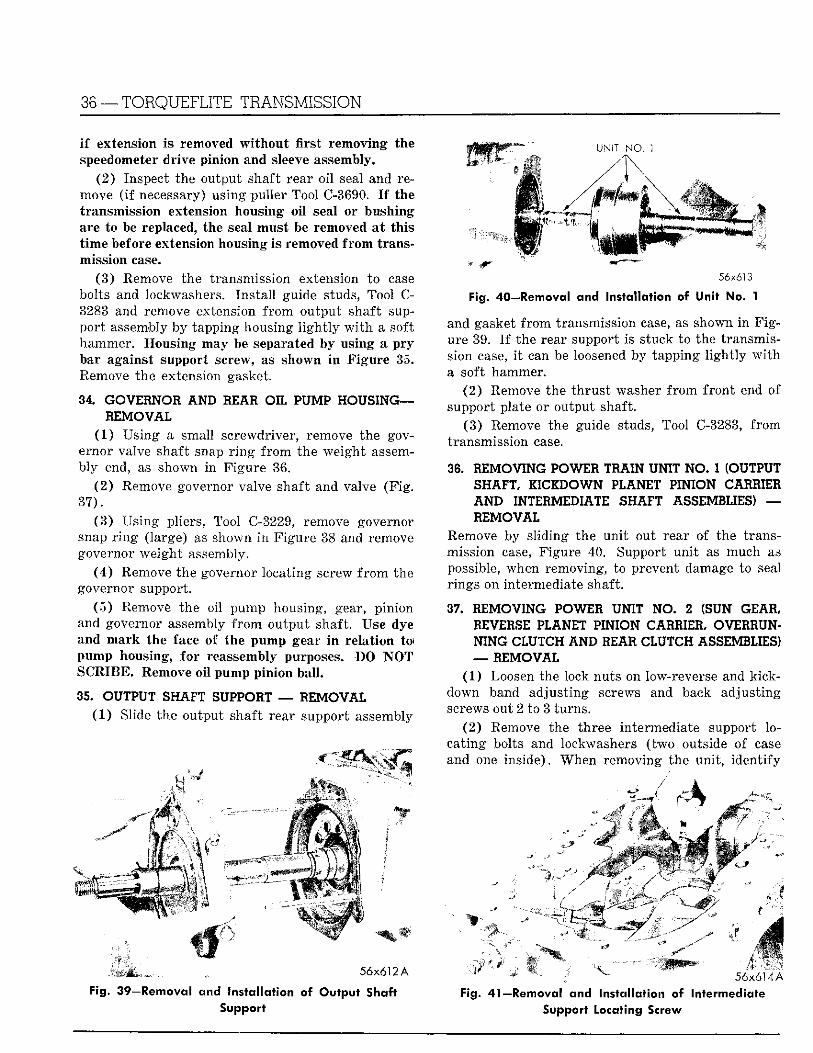
36 — TORQUEFLITE TRANSMISSION
I f extension Is removed w i t h o u t first removing the speedometer drive pinion and sleeve assembly.
(2 ) Inspect the output shaft rear o i l seal and remove ( i f necessary) using puller Tool C-3690. I f the transmission extension housing o i l seal or bushing are to be replaced, the seal must be removed a t this t ime before extension housing is removed f r o m transmission case.
(3 ) Remove the transmission extension to case bolts and lockwashers. Ins ta l l guide studs, Tool C-3283 and remove extension f r o m output shaft suppor t assembly by tapping housing l i g h t l y w i t h a soft hammer. Housing may be separated by using a p ry bar against support screw, as shown i n F igure 35. Remove the extension gasket.
34. GOVERNOR AND REAR OIL PUMP HOUSING— REMOVAL
(1 ) Us ing a small screwdriver, remove the governor valve shaft snap r i n g f r o m the weight assembly end, as shown i n F igure 36.
(2 ) Remove governor valve shaft and valve (F ig . 37) .
( 3 ) Us ing pliers, Tool C-3229, remove governor snap r i n g (large) as shown i n F igure 38 and remove governor weight assembly.
(4 ) Remove the governor locating screw f r o m the governor support.
(5 ) Remove the oil pump housing, gear, p in ion and governor assembly f r o m output shaft. Use dye and mark the face of the pump gear i n relat ion to) pump housing, fo r reassembly purposes. DO N O T SCRIBE. Remove oi l pump pinion bal l .
35. OUTPUT SHAFT SUPPORT — REMOVAL (1 ) Slide the output shaft rear support assembly
^ ^ ^ ^ ^ UNIT N O . 1
56x613
Fig. 40—Removal and Installation of Unit No. 1
and gasket f r o m transmission case, as shown i n F i g ure 39. I f the rear support is stuck to the transmission case, i t can be loosened by tapping l i g h t l y w i t h a soft hammer.
(2 ) Remove the th rus t washer f r o m f ron t end of support plate or output shaft.
(3 ) Remove the guide studs, Tool C-3283, f rom transmission case.
36. REMOVING POWER TRAIN UNIT NO. 1 (OUTPUT SHAFT, KICKDOWN PLANET PINION CARRIER A N D INTERMEDIATE SHAFT ASSEMBLIES) — REMOVAL
Remove by sl iding the un i t out rear of the transmission case, Figure 40. Support un i t as much as possible, when removing, to prevent damage to seal r ings on intermediate shaft.
37. REMOVING POWER UNIT NO. 2 (SUN GEAR, REVERSE PLANET PINION CARRIER, OVERRUNNING CLUTCH AND REAR CLUTCH ASSEMBLIES) — REMOVAL
(1) Loosen the lock nuts on low-reverse and kick-down band adjust ing screws and back adjust ing screws out 2 to 3 turns.
(2) Remove the three intermediate support locat ing bolts and lockwashers ( two outside of case and one inside). When removing the uni t , ident i fy
1HM • i
56x612 A
Fig. 39—Removal and Installation of Output Shaft Support
5 6 x 6 1 4 A Fig. 41—Removal and Installation of Intermediate
Support Locating Screw
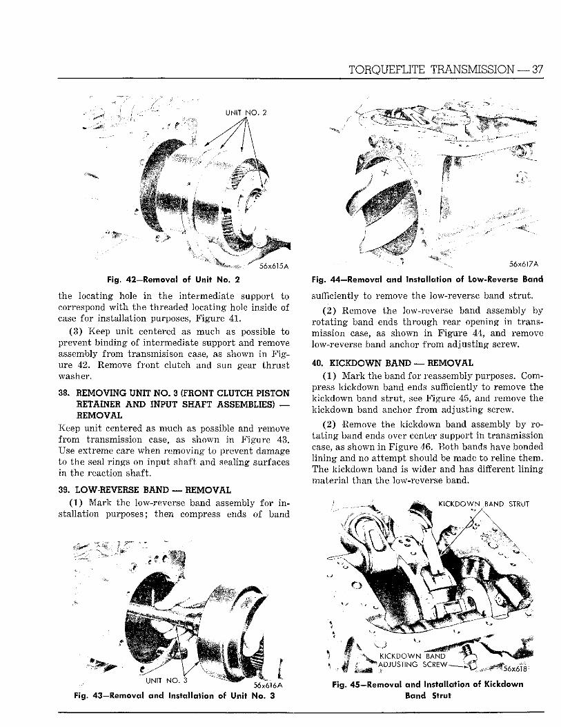
TORQUEFLITE TRANSMISSION — 37
UNIT N O . 2
56x615 A
Fig. 42—Removal of Unit No. 2
the locating hole i n the intermediate support to correspond w i t h the threaded locating hole inside of case for instal lat ion purposes, F igure 41.
( 3 ) Keep un i t centered as much as possible to prevent binding of intermediate support and remove assembly f rom transmisison case, as shown i n F i g ure 4 2 . Remove f ron t c lutch and sun gear t h ru s t washer.
38. REMOVING UNIT N O . 3 (FRONT CLUTCH PISTON RETAINER AND INPUT SHAFT ASSEMBLIES) — REMOVAL
Keep un i t centered as much as possible and remove f r o m transmission case, as shown i n Figure 4 3 . Use extreme care when removing to prevent damage to the seal r ings on input shaft and sealing surfaces in the reaction shaft.
39. LOW-REVERSE BAND — REMOVAL ( 1 ) .Mark the low-reverse band assembly for i n
stal lat ion purposes; then compress ends o f band
56x617A
Fig. 44—Removal and Installation ©f low-Reverse Band
sufficiently to remove the low-reverse band s t ru t .
(2 ) Remove the low-reverse band assembly by r o t a t i n g band ends t h rough rear opening i n transmission case, as shown i n F igure 44, and remove low-reverse band anchor f r o m adjust ing screw.
40. 1 I C 1 D O W N BAND — REMOVAL (1) M a r k the band for reassembly purposes. Com
press kickdown band ends sufficiently to remove the k ickdown band s t ru t , see Figure 45, and remove the k ickdown band anchor f r o m adjust ing screw.
(2 ) Remove the kickdown band assembly by rot a t i n g band ends over center support i n transmission case, as shown i n Figure 46. B o t h bands have bonded l i n i n g and no a t tempt should be made to reline them. The kickdown band is wider and has different l i n i n g mater ia l than the low-reverse band.
nrKDOWN BAND STRUT
UNIT NO. 3 , A A l A A
56x616A Fig. 43—Removal and Installation of Unit No. 3
KICKDOWN BAND ADJUSTING SCREW 56x618
Fig. 45—Removal and Installation of Kickdown Band Strut
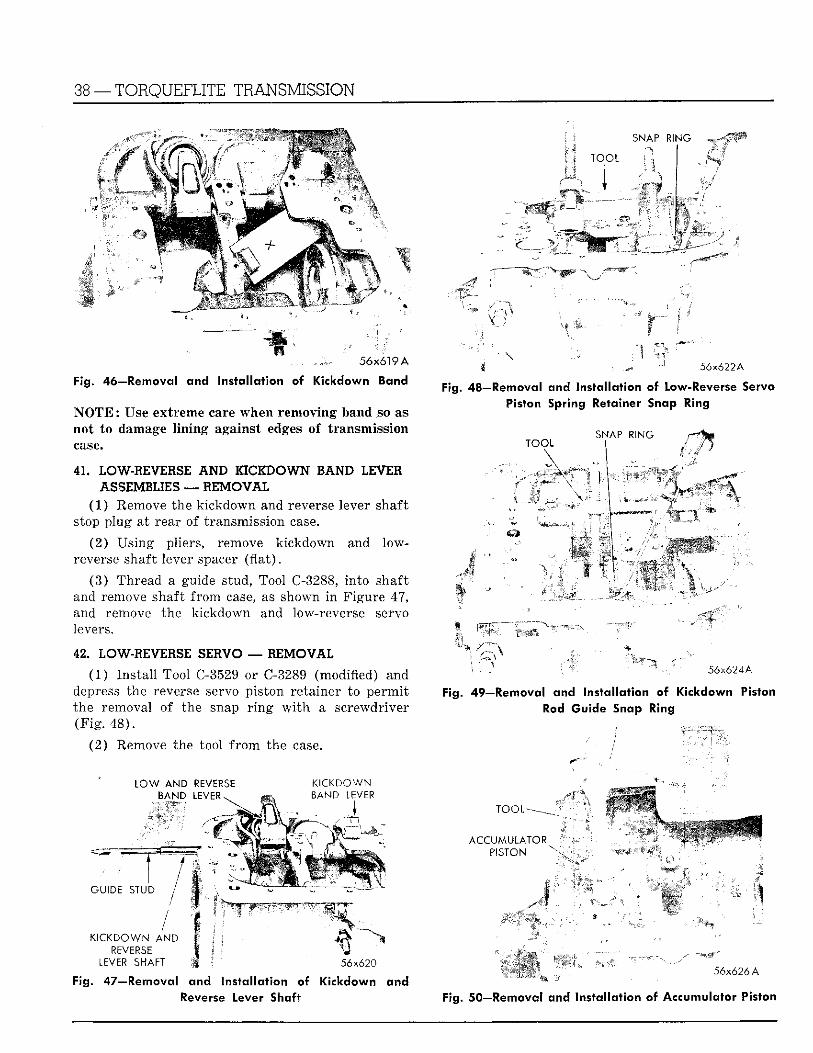
38 —TORQUEFLITE TRANSMISSION
TOOL
SNAP RING ,
56x619 A
Fig. 46—Removal and Installation of Kickdown Band
N O T E : Use extreme care when removing band so as not to damage lining against edges of transmission case.
41. LOW-REVERSE AND KICKDOWN BAND LEVE1 ASSEMBLIES — REMOVAL
(1) Remove the k ickdown and reverse lever shaft stop plug at rear of transmission case.
(2) Us ing pliers, remove kickdown and low-reverse shaft lever spacer ( f l a t ) .
(3 ) Thread a guide stud, Tool C-3288, in to shaft and remove shaft f rom case, as shown i n Figure 47, and remove the kickdown and low-reverse servo levers.
42. LOW-REVERSE SERVO — REMOVAL
(1) Ins ta l l Tool C-3529 or C-3289 (modified) and depress the reverse servo piston retainer to pe rmi t the removal of the snap r i n g w i t h a screwdriver (F ig . 48) .
(2) Remove the tool f r o m the case.
56x622A
Fig. 4 8 — Remova l a n d Installation of Low-Reverse Servo Piston Spring Retainer Snap Ring
TOOL
\
SNAP RING
mm
i l l
m
56x624A
Fig. 49—Removal and Installation of Kickdown Piston Rod Guide Snap Ring
L O W AND REVERSE BAND LEVER
K I C K D O W N BAND LEVER
• • y S ) B j | l i b
GUIDE STUD
K I C K D O W N AND REVERSE
LEVER SHAFT
mm 56x620
Fig. 47—Removal and Installation of Kickdown and Reverse Lever Shaft
T O O L -
ACCUMULATOR PISTON
• I 56x626 A
Fig. 50—Removal and installation ©f Accumulator Piston
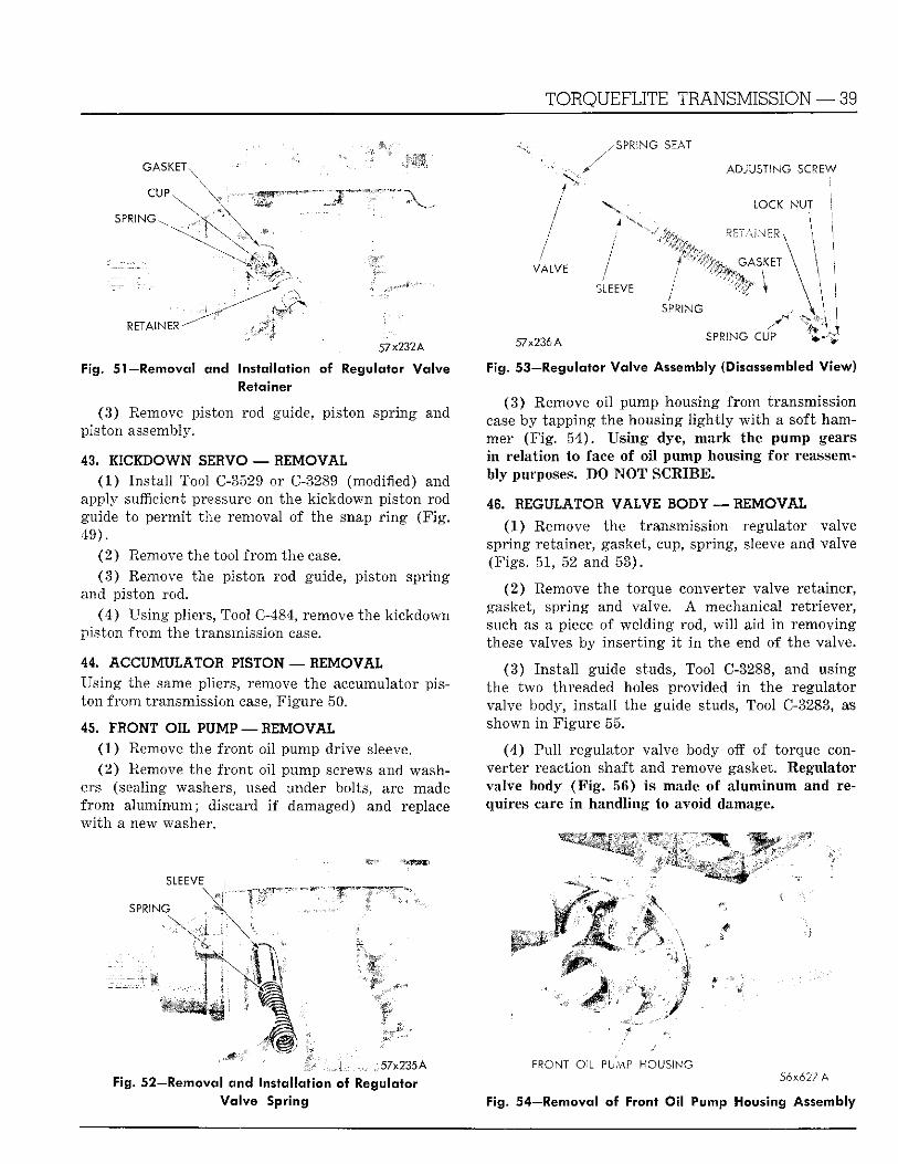
T O R Q U E F L I T E T R A N S M I S S I O N — 39
.SPRING SEAT
ADJUSTING SCREW
RETAINER-
57x232A
Fig. 51—Removal and Installation of Regulator Valve Retainer
(3) Remove piston rod guide, piston spring and piston assembly.
43. KICKDOWN SEBVO — REMOVAL (1) Ins ta l l Tool C-3529 or C-3289 (modified) and
apply sufficient pressure on the kickdown piston rod guide to permi t the removal of the snap r i n g (F ig . 49) .
(2 ) Remove the tool f r o m the case. (3 ) Remove the piston rod guide, piston spring
and piston rod. (4) Using pliers, Tool C-484, remove the kickdown
piston f rom the transmission case.
44. ACCUMULATOR PISTON — REMOVAL Using the same pliers, remove the accumulator piston f rom transmission case, Figure 50.
45. FRONT OIL PUMP — R E M O V A L (1) Remove the f ron t oil pump drive sleeve. ( 2 ) Remove the f ron t oil pump screws and wash
ers (sealing washers, used under bolts, are made f r o m a luminum; discard i f damaged) and replace w i t h a new washer.
SLEEVE
SPRING E M
MM
VALVE
SLEEVE
SPRING
57x236A SPRING CU? t \
Fig. 53—Regulator Valve Assembly (Disassembled View)
(3) Remove oi l pump housing f rom transmission case by tapping the housing l i g h t l y w i t h a soft hammer (F ig . 54) . Us ing dye, mark the pump gears i n relat ion to face of o i l pump housing fo r reassembly purposes. DO N O T SCRIBE.
48. REGULATOR VALVE BODY — REMOVAL
(1) Remove the transmission regulator valve spring retainer, gasket, cup, spring, sleeve and valve (Figs. 51, 52 and 53) .
(2) Remove the torque converter valve retainer, gasket, spr ing and valve. A mechanical retriever, such as a piece of welding rod, w i l l aid i n removing these valves by inser t ing i t i n the end of the valve.
(3) Ins ta l l guide studs, Tool C-3288, and using the two threaded holes provided i n the regulator valve body, ins ta l l the guide studs, Tool C-3283, as shown i n F igure 55.
(4) Pul l regulator valve body off of torque converter reaction shaft and remove gasket. Regulator valve body ( F i g . 56) is made of a luminum and requires care i n handl ing to avoid damage.
H Q
J7x235A
Fig. 52—Removal and Installation of Regulator Valve Spring
F R O N T O ' L PbVvP H O U S I N G 5 6 x 6 2 7 A
Fig 54—Removal of Front Oil Pump Housing Assembly
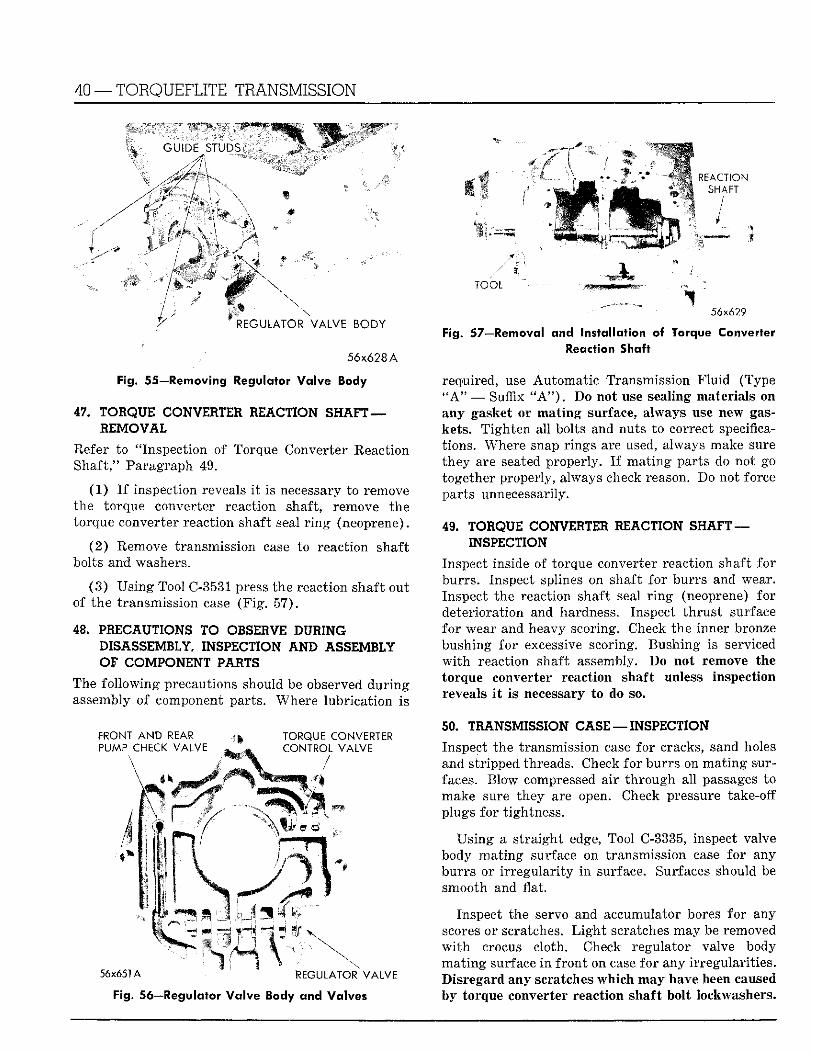
40 —TORQUEFLITE TRANSMISSION
REACTION SHAFT
/
T O O L
REGULATOR VALVE BODY
56x628A
- Fig. 55—Removing Regulator Va lve Body
47. TORQUE CONVERTER. REACTION SHAFT — REMOVAL
Refer to "Inspection of Torque Converter Reaction Shaft," Paragraph 49.
( 1 ) I f inspection reveals i t is necessary to remove the torque converter reaction shaft, remove the torque converter reaction shaft seal r i n g (neoprene).
( 2 ) Remove transmission case to reaction shaft bolts and washers.
( 3 ) Us ing Tool C-3531 press the reaction shaft out of the transmission case ( F i g . 57) .
48. PRECAUTIONS TO OBSERVE DURING DISASSEMBLY, INSPECTION AND ASSEMBLY OF COMPONENT PARTS
The fo l lowing precautions should be observed d u r i n g assembly of component parts. Where lubr ica t ion is
56x629
Converter
FRONT AND REAR PUMP CHECK VALVE
TORQUE CONVERTER CONTROL VALVE
I
56x651 A REGULATOR VALVE
Fig. 56—Regulator Va lve Body and Valves
57—Removal and Installation « Reaction Shaft
required, use Automat ic Transmission F lu id (Type " A " — Suffix " A " ) . Do not use sealing materials on any gasket or mat ing surface, always use new gaskets. T igh ten all bolts and nuts to correct specifications. Where snap rings are used, always make sure they are seated properly. I f ma t ing parts do not go together properly, always check reason. Do not force parts unnecessarily.
49. TORQUE CONVERTER REACTION SHAFT — INSPECTION
Inspect inside of torque converter reaction shaft fo r burrs . Inspect splines on shaft for burrs and wear. Inspect the reaction shaft seal r i n g (neoprene) for deterioration and hardness. Inspect t h rus t surface fo r wear and heavy scoring. Check the inner bronze bushing for excessive scoring. Bushing is serviced w i t h reaction shaft assembly. Do not remove the torque converter reaction shaft unless inspection reveals i t is necessary to do so.
50. TRANSMISSION CASE — INSPECTION
Inspect the transmission case for cracks, sand holes and stripped threads. Check for burrs on ma t ing surfaces. Blow compressed air t h rough all passages to make sure they are open. Check pressure take-off plugs for tightness.
Us ing a s t ra ight edge, Tool C-3335, inspect valve body ma t ing surface on transmission case for any burrs or i r r egu la r i ty i n surface. Surfaces should be smooth and flat.
Inspect the servo and accumulator bores for any scores or scratches. L i g h t scratches may be removed w i t h crocus cloth. Check regulator valve body ma t ing surface i n f ron t on case for any i r regular i t ies . Disregard any scratches which may have been caused by torque converter reaction shaft bolt lockwashers.
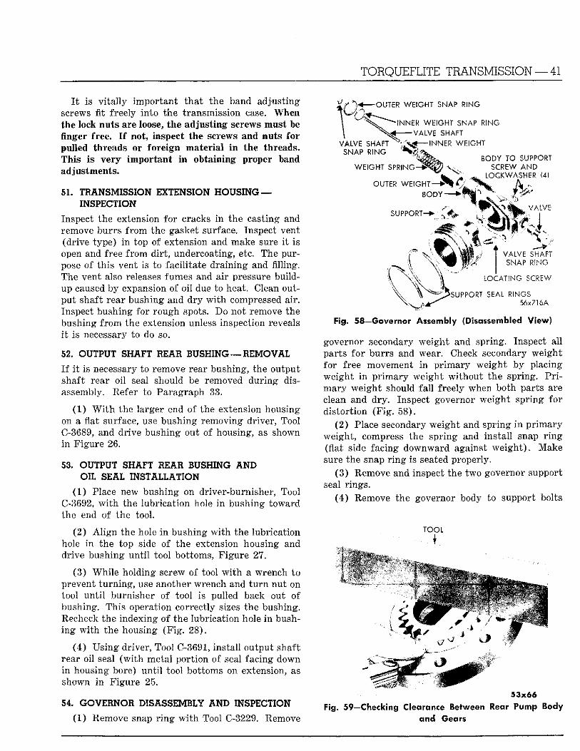
TORQUEFLITE TRANSMISSION — 41
I t is v i t a l l y impor tan t t h a t the band adjust ing screws fit freely into the transmission case. When the lock nuts are loose, the adjust ing screws must be finger free. I f not, inspect the screws and nuts fo r pulled threads or fore ign mater ia l i n the threads. This Is ve ry impor tan t i n obtaining proper band adjustments.
51. TRANSMISSION EXTENSION HOUSING — INSPECTION
Inspect the extension for cracks i n the casting and remove burrs f rom the gasket surface. Inspect vent (drive type) i n top of extension and make sure i t is open and free f rom d i r t , undercoating, etc. The purpose of th is vent is to fac i l i ta te dra in ing and filling. The vent also releases fumes and air pressure bui ldup caused by expansion of o i l due to heat. Clean output shaft rear bushing and d r y w i t h compressed air. Inspect bushing for rough spots. Do not remove the bushing f r o m the extension unless inspection reveals i t is necessary to do so.
52. OUTPUT SHAFT REAR RUSHING — R E M O V A L
I f i t is necessary to remove rear bushing, the output shaft rear o i l seal should be removed dur ing disassembly. Refer to Paragraph 33.
(1) W i t h the larger end of the extension housing on a flat surface, use bushing removing driver, Tool C-3689, and dr ive bushing out of housing, as shown i n F igure 26.
53. OUTPUT SHAFT REAR BUSHING 4ND OIL SEAL INSTALLATION
(1) Place new bushing on driver-burnisher, Tool C-3692, w i t h the lubr icat ion hole i n bushing toward the end of the tool .
(2 ) A l i g n the hole i n bushing w i t h the lubricat ion hole i n the top side of the extension housing and drive bushing u n t i l tool bottoms, F igure 27.
(3 ) Whi le holding screw of tool w i t h a wrench to prevent t u rn ing , use another wrench and t u r n nu t on tool u n t i l burnisher of tool is pulled back out of bushing. This operation correctly sizes the bushing. Recheck the indexing of the lubricat ion hole i n bushing w i t h the housing ( F i g . 28) .
(4 ) Us ing driver, Tool C-3691, instal l output shaft rear oil seal ( w i t h metal por t ion of seal facing down i n housing bore) u n t i l tool bottoms on extension, as shown i n Figure 25.
54. GOVERNOR DISASSEMBLY A N D INSPECTION
(1) Remove snap r i n g w i t h Tool C-3229. Remove
OUTER WEIGHT SNAP RING
^ ! N N E R WEIGHT SNAP RING VALVE SHAFT
VALVE SHAFT — I N N E R WEIGHT SNAP RING
WEIGHT SPRING-*- v /
OUTER WEIGH!"—> B O D Y ' - - - >
SUPPORT-**
BODY TO SUPPORT SCREW AND
LOCKWASHER (4)
• r . - V/.'lVE
SNAP RING I
LOCATING SCREW
\ ^ S U P P '
Fig. 58—Governor Assembly (Disassembled View)
-\ - ^ o u r v O R T SEAL RINGS ^ \ 56x716A
governor secondary we igh t and spring. Inspect a l l parts fo r burrs and wear. Check secondary weight for free movement i n p r imary weight by placing weight i n p r imary weight w i thou t the spring. P r i mary weigh t should f a l l freely when both parts are clean and dry . Inspect governor weight spr ing fo r d is tor t ion (F ig . 58) .
(2) Place secondary weight and spr ing i n p r imary weight , compress the spring and ins ta l l snap r i n g (flat side facing downward against w e i g h t ) . Make sure the snap r i n g is seated properly.
(3 ) Remove and inspect the two governor support seal r ings.
(4 ) Remove the governor body to support bolts
T O O L
•1
5 3 x 6 6
Fig. 59—Checking Clearance Between Rear Pump Body and Gears
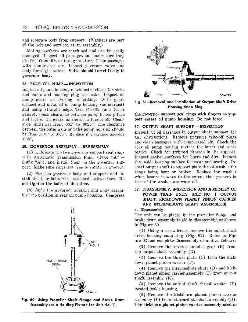
42 — T O R Q U E F L I T E TRANSMISSION
and separate body f r o m support. (Washers are par t of the bolt and serviced as an assembly.)
M a t i n g surfaces are machined and can be easily damaged. Inspect oil passages and.make sure they are free f r o m d i r t or foreign matter . Clean passages w i t h compressed air. Inspect governor valve and body for s l ight scores. Valve should t ravel freely i n governor body.
55. BEAR OIL PUMP — INSPECTION Inspect oi l pump housing machined surfaces for nicks and burrs and housing plug for leaks. Inspect oi l pump gears for scoring or p i t t i n g . W i t h gears cleaned and installed i n pump housing (as marked) and using s t ra ight edge, Tool C-3335 (and feeler gauge), check clearance between pump housing face and face of the gears, as shown i n Figure 59. Clearance l imi t s are f r o m .001" to .0025". The clearance between the outer gear and the pump housing should be f rom .004" to .006". Replace i f clearance exceeds .008".
56. G O V E R N O R A S S E M B L Y — R E A S S E M B L Y
(1) Lubricate the two governor support seal r ings w i t h Automat ic Tranmission F lu id (Type . "A" — Suffix " A " ) , and insta l l them on the governor support . Make sure r ings are free to rotate i n grooves.
(2) Posit ion governor body and support and i n stall the four bolts w i t h attached lockwashers. Do not t i gh ten the bolts at t h i s t ime.
(3) Slide the governor support and body assembly into position i n rear oil pump housing. Compress
_ \ UNIT / N O . 1
HAND BRAKE DRUM
\
56x632
56x633
Fig. 60—Using Propeller Shaft Flange and Brake Drum Assembly (as a Holding Fixture for Unit No. 1)
Fig. 61—Removal and Installation of Output Shaft Drive Housing Snap Ring
the governor support seal r ings w i t h fingers as support enters o i l pump housing. Do not force.
57. OUTPUT SHAFT S U P P O R T — INSPECT ION
Inspect al l oil passages i n output shaft support for any obstructions. Remove pressure take-off plugs and clean passages w i t h compressed air . Check the rear oil pump mat ing surface for burrs and score marks. Check for stripped threads in the support. Inspect gasket surfaces for burrs and d i r t . Inspect the inside bearing surface for wear and scoring. I n spect output shaft to support plate th rus t washer for tangs being bent or broken. Replace the washer when bronze is worn to the extent tha t grooves i n face of the washer are worn off.
58. D I SASSEMBLY, INSPECT ION A N D A S S E M B L Y OF POWER TRAIN UNITS, UNIT NO. 1 (OUTPUT
SHAFT, KIC1DOWN P LANET P IN ION C A R R I E R
AND INTERMED IATE S H A F T ASSEMBL IES )
a. Disassembly The un i t can be placed i n the propeller flange and brake d r u m assembly to aid i n disassembly, as shown i n Figure 60.
(1 ) Using a screwdriver, remove the ouput shaft dr ive housing snap r i n g (F ig . 61) . Refer to F i g ure 62 and complete disassembly of un i t as fo l lows:
( 2 ) Remove the reverse annulus gear (B) f r o m the output shaft assembly ( K ) .
( 3 ) Remove the t h rus t plate (C) f r o m the k ick-down planet pinion carr ier ( F ) .
( 4 ) Remove the intermediate shaft (D) and kick-down planet pinion carrier assembly (F ) f r o m output shaft assembly ( K ) .
( 5 ) Remove the output shaft t h rus t washer (E ) located inside housing.
( 6 ) Remove the kickdown planet pinion carrier assembly (F ) f r o m intermediate shaft assembly ( D ) . The kickdown planet pinion carr ier assembly used i n
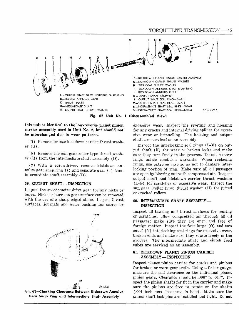
TORQUEFLITE TRANSMISSION — 43
A — OUTPUT SHAFT DRIVE HOUSING SNAP RING B-REVERSE ANNULUS GEAR C —THRUST PLATE D—INTERMEDIATE SHAFT E—OUTPUT SHAFT THRUST WASHER
F—KICKDOWN PLANET PINION CARRIER ASSEMBLY G — K I C K D O W N CARRIER THRUST WASHER H — S U N GEAR THRUST WASHER
l - K I C K D O W N ANNULUS GEAR SNAP RING J — KICKDOWN ANNULUS GEAR K - O U T P U T SHAFT ASSEMBLY L—OUTPUT SHAFT SEAL R ING-SMALL
M —OUTPUT SHAFT SEAL RING —LARGE N —INTERMEDIATE SHAFT SEAL R I N G - S M A L L O-INTERMEDIATE SHAFT SEAL RING —LARGE 56 x 709 A
Fig. 62—Unit No. 1 (Disassembled View)
th is uni t is identical to the low-reverse planet pinion carrier assembly used i n U n i t No. 2, but should not be interchanged due to wear patterns.
(7 ) Remove bronze kickdown carr ier t h rus t washer ( G ) .
(8) Remove the sun gear roller type th rus t washer ( H ) f r o m the intermediate shaft assembly ( D ) .
(9) W i t h a screwdriver, remove kickdown annulus gear snap r i n g (1) and separate gear (J) f r o m intermediate shaft assembly ( D ) .
59. OUTPUT SHAFT — INSPECTION
Inspect the speedometer drive gear for any nicks or burrs . Nicks or burrs on gear surface can be removed w i t h the use of a sharp edged stone. Inspect t h r u s t surfaces, journals and inner bushing for scores or
|. 56x634
Fig. 63—Checking Clearance Between Kickdown Annulus Gear Snap Ring and Intermediate Shaft Assembly
excessive wear. Inspect the r i v e t i n g and housing for any cracks and in ternal d r iv ing splines for excessive wear or br innel l ing. The housing and output shaft are serviced as an assembly.
Inspect the in ter locking seal r ings ( L - M ) on output shaft ( K ) for wear or broken locks and make sure they t u r n freely i n the grooves. Do not remove r ings unless condition warrants . When replacing r ings, use extreme care so as not to damage interlocking por t ion of r i n g . Make sure al l oi l passages are open by blowing out w i t h compressed air. Inspect output shaft and k ickdown carr ier t h rus t washers (E-G) fo r scratches or excessive wear. Inspect the sun gear (rol ler type) th rus t washer ( H ) fo r p i t ted or cracked rollers.
60. INTERMEDIATE SHAFT ASSEMBLY — INSPECTION
Inspect al l bearing and th rus t surfaces for scoring or scratches. Blow compressed air t h rough al l oi l passages; make sure they are open and free of foreign mat ter . Inspect the four large ( 0 ) and two small ( N ) in ter locking seal r ings for excessive wear, broken ends and make sure they rotate freely i n the grooves. The intermediate shaft and clutch feed tubes are serviced as an assembly.
6 1 . I 1 C I D O W N PLANET PINION CARRIER ASSEMBLY — INSPECTION
Inspect planet p inion carr ier fo r cracks and pinions for broken or w o r n gear teeth. Us ing a feeler gauge, measure the end clearance on the individual planet pinion gears. Clearance should be .006" to .017". I n spect the pinion shafts for fit i n the carr ier and make sure the pinions are free to rotate on the shafts (.001 inch max. looseness i n hole) . Make sure the pinion shaft lock pins are installed and t i gh t . Do not
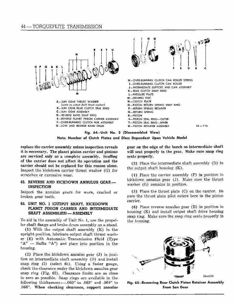
44 —TORQUEFLITE TRANSMISSION
H o
1 I T U
O P Q A K L
H i k4l'4VJ -v.
M
A - S U N GEAR THRUST WASHER (same as output shaft thrust washer)
B - S U N GEAR REAR CLUTCH SEAL RING C - S U N GEAR ASSEMBLY D-REVERSE BAND SNAP RING E-REVERSE PLANET PINION CARRIER ASSEMBLY F—OVER-RUNNING CLUTCH HUB ASSEMBLY G - L O W AND REVERSE BAND DRUM
f " v 1
F E D B
H-OVER-RUNNING CLUTCH CAM ROLLER SPRING I —OVER-RUNNING CLUTCH CAM ROLLER J-INTERMEDIATE SUPPORT AND CAM ASSEMBLY K - R E A R CLUTCH SNAP RING L—PRESSURE PLATE
M —DRIVING DISC N —CLUTCH PLATE O - P I S T O N RETURN SPRING SNAP RING P —RETURN SPRING RETAINER Q - R E T U R N SPRING R - P I S T O N S - P I S T O N SEAL R I N G - O U T E R T - P I S T O N SEAL RING—INNER
U —PISTON RETAINER ASSEMBLY 56 x 710
Fig. 64—Unit No. 2 (Disassembled View)
Note: Number of Clutch Plates and Discs Dependent Upon Vehicle Model
replace the carr ier assembly unless inspection reveals i t is necessary. The planet pinion carr ier and pinions are serviced only as a complete assembly. Scuffing of the carr ier does not affect i t s operation and the carrier should not be replaced for th i s reason alone. Inspect the k ickdown carr ier t h rus t washer (G) for scratches or excessive wear.
62. REVERSE A N D K I C I D O W N ANNULUS GEAH — INSPECTION
Inspect the annulus gears for worn , cracked or broken gear teeth.
63 . UNIT NO. 1 (OUTPUT SHAFT, I I C I D O W N PLANET PINION CARRIER A N D INTERMEDIATE SHAFT ASSEMBLIES) —ASSEMBLY
To aid i n the assembly of U n i t No. 1, use the propeller shaft flange and brake d r u m assembly as a stand.
(1) W i t h the output shaft assembly ( K ) i n the up r igh t position, lubricate output shaft t h r u s t washer (E ) w i t h Automat i c Transmission F l u i d (Type " A " — Suffix " A " ) and place in to posit ion i n the housing.
(2 ) Place the k ickdown annulus gear (J ) i n posit i on on intermediate shaft assembly ( D ) and ins ta l l snap r i n g ( I ) (select fit). Us ing a feeler gauge, check the clearance under the k ickdown annulus gear snap r i n g ( F i g . 63) . Clearance l i m i t s are as close to zero as possible. Snap r ings are available i n the fo l lowing thicknesses:—.060" to .062" and .064" to .066". When checking clearance, support annulus
gear on the edge of the bench so intermediate shaft w i l l seat properly i n the gear. Make sure snap r i n g seats properly.
( 3 ) Place the intermediate shaft assembly (D) i n the output shaft housing ( K ) .
( 4 ) Place the carrier assembly (F ) i n position i n k ickdown annulus gear ( J ) . Make sure the t h r u s t washer (G) remains i n position.
( 5 ) Place the th rus t plate (C) on the carrier. Be sure the t h rus t plate pi lot enters bore i n the pinion carrier.
(6 ) Place reverse annulus gear (B) i n position i n housing ( K ) and instal l output shaft dr ive housing snap r i ng . Make sure the snap r i n g seats properly i n the housing.
56x636
Fig. 65—Removing Rear Clutch Piston Retainer Assembly From Sun Gear
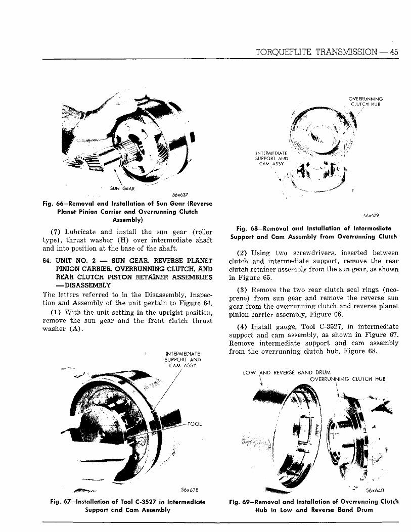
TORQUEFLITE TRANSMISSION — 45
OVERRUNNING CLUTCH HUB
SUN GEAR 5£x637
Fig. 66—Removal and Installation of Sun Gear (Reverse Planet Pinion Carrier and Overrunning Clutch
Assembly)
(7 ) Lubricate and instal l the sun gear (roller t y p e ) , t h rus t washer ( H ) over intermediate shaft and in to position at the base of the shaft.
84 UNIT NO. 2 — SUN GEAR, REVERSE PLANET PINION CARRIER, OVERRUNNING CLUTCH, AND REAR CLUTCH PISTON RETAINER ASSEMBLIES — DISASSEMBLY
The letters referred to i n the Disassembly, Inspect ion and Assembly of the un i t per ta in to F igure 64.
(1) W i t h the un i t set t ing i n the up r igh t position, remove the sun gear and the f ron t clutch t h rus t washer ( A ) .
INTERMEDIATE SUPPORT AND
CAM ASSY
-TOOL
- * -. 56x638
Fig. 67—installation of Tool €=3527 in Intermediate Support and Cam Assembly
INTERMEDIATE SUPPORT AND
CAM ASSY
! :
56x639
Fig. 68—Removal and Installation of Intermediate Support and Cam Assembly from Overrunning Clutch
(2) Us ing two screwdrivers, inserted between clutch and intermediate support, remove the rear clutch retainer assembly f r o m the sun gear, as shown i n F igure 65.
(3 ) Remove the two rear clutch seal r ings (neoprene) f r o m sun gear and remove the reverse sun gear f r o m the overrunning clutch and reverse planet pinion carrier assembly, F igure 66.
( 4 ) Ins ta l l gauge, Tool C-3527, i n intermediate support and cam assembly, as shown i n Figure 67. Remove intermediate support and cam assembly f r o m the overrunning clutch hub, Figure 68.
LOW AND REVERSE BAND DRUM ^ OVERRUNNING CLUTCH HUB
• 56x640
Fig. 69—Removal and Installation of Overrunning Clutch Hub in Low and Reverse Band Drum
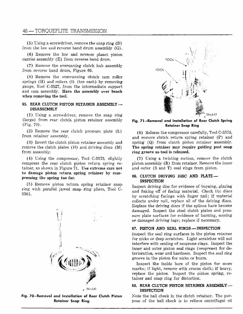
46 — TORQUEFLITE TRANSMISSION
(5 ) Us ing a screwdriver, remove the snap r i n g (D) f r o m the low and reverse band d r u m assembly ( G ) .
(6) Remove the low and reverse planet pinion carrier assembly ( E ) f r o m reverse band drum.
(7) Remove the overunning clutch hub assembly f r o m reverse band drum, F igure 69.
(8) Remove the overrunning clutch cam roller springs ( H ) and rollers ( I ) ( ten each) by removing gauge, Tool C-3527, f r o m the intermediate support and cam assembly. Have the assembly over bench when removing the tool.
65. BEAU CLUTCH PISTON 1ETAINEH ASSEMBLY — DISASSEMBLY
(1 ) Us ing a screwdriver, remove the snap r i n g (large) f r o m rear clutch pis ton retainer assembly ( F i g . 70) .
(2) Remove the rear clutch pressure plate ( L ) f r o m retainer assembly.
(3 ) Inve r t the clutch piston retainer assembly and remove the clutch plates ( H ) and d r i v i n g discs ( M ) f r o m assembly.
(4 ) Us ing the compressor, Tool C-3575, s l igh t ly compress the rear clutch piston r e tu rn spring retainer, as shown i n Figure 71 . Use extreme care not t o damage piston r e t u r n spr ing retainer by compressing the spr ing too far .
(5 ) Remove piston r e t u r n spr ing retainer snap r i n g w i t h parallel jawed snap r i n g pliers, Tool C-3301.
56x641
Fig. 70—Removal and Installation of Rear Clutch Piston Retainer Snap Ring
T O O L \
TOOL
56x643
Fig. 71—Removal and Installation of Rear Clutch Spring Retainer Snap Ring
(6 ) Release the compressor carefully, Tool C-3575, and remove clutch r e tu rn spring retainer (P) and spr ing (Q) f r o m clutch piston retainer assembly. The spr ing retainer may require guid ing past snap r i n g groove as tool is released.
(7 ) Us ing a t w i s t i n g motion, remove the clutch piston assembly (R) f r o m retainer. Remove the inner and outer (S and T ) seal r ings f r o m piston.
66. CLUTCH D11V1NG DISC AND PLATE — INSPECTION
Inspect d r i v i n g disc fo r evidence of burning, glazing and flaking off of facing mater ial . Check the discs by scratching facings w i t h finger nail;. i f mater ia l collects under nai l , replace all of the d r i v i n g discs. Replace the d r i v i n g discs i f the splines have become damaged. Inspect the steel clutch plates and pressure plate surfaces for evidence of burning , scoring or damaged d r i v i n g lugs; replace i f necessary.
67. PISTON A N D SEAL HINGS — INSPECTION Inspect the seal r i n g surfaces i n the piston retainer fo r nicks or deep scratches. L i g h t scratches w i l l not interfere w i t h sealing of neoprene r ings. Inspect the inner and outer piston seal r ings (neoprene) for deter iora t ion , wear and hardness. Inspect the seal r i n g groove i n the piston for nicks or burrs .
Inspect the inside bore of the piston fo r score m a r k s ; i f l i gh t , remove w i t h crocus c lo th ; i f heavy, replace the piston. Inspect the piston spring, reta iner and snap r i n g for dis tor t ion.
68. BEAU CLUTCH PISTON BETAINER ASSEMBLY — INSPECTION
Note the ball check i n the clutch retainer. The purpose of the ball check is to relieve centr ifugal oi l
TORQUEFLITE TRANSMISSION — 47
pressure and to prevent par t ia l clutch engagement when the transmission is in neutra l or operating i n drive (breakaway) when the engine speeds are i n creased; otherwise, clutch may engage. Make sure the ball operates freely.
Inspect the band contacting surface fo r deep scores and burns, especially i f the band l i n ing is worn to the point where the steel band has been contacting the rear clutch piston retainer. Do not machine the piston retainer i n a lathe to remove score marks.
Inspect the steel clutch plate contacting surfaces for burrs or br inel l ing. Make sure the clutch d r i v i n g lugs on steel plates t ravel freely in to retainer. Remove any metal pickup on the hub of retainer.
69. REAR CLUTCH PISTON RETAINER — ASSEMBLY
(1 ) Lubricate and instal l inner piston seal r i n g (T) on hub of clutch retainer. Make sure tha t the l ip of the seal is facing down and the seal Is properly seated i n groove.
(2 ) Lubr icate and instal l the outer seal r i n g (S) on clutch piston ( l ip of seal toward piston head).
( 3 ) Place the piston assembly (R) in the clutch retainer ( U ) and w i t h a t w i s t i n g motion, seat the piston i n bot tom of the retainer.
(4 ) Ins ta l l the piston r e tu rn spr ing on hub and posit ion spr ing retainer and snap r i n g on spring.
( 5 ) Us ing a compressor, Tool C-3575, compress the clutch spr ing sufficiently to permi t the snap r i n g to enter the groove in the hub and snap the r i n g i n place as shown i n Figure 7 1 . The pis ton spring retainer may require guiding past the clutch hub. Make very sure the snap r i n g is properly seated.
(6 ) Remove the compressor, Tool C-3575.
(7) Lubricate all clutch plates and drive discs w i t h Automat ic F l u i d (Type " A " — Suffix " A , J ) . Assemble by placing one of the rear clutch steel plates i n the clutch retainer followed by a d r i v i n g disc. Al te rna te ly repeat th is procedure u n t i l all discs and plates have been installed.
The number of discs and plates va ry according to the engine and transmission equipment. The rear clutch pistons are of various thicknesses. Therefore, the correct piston must always be used w i t h the number of discs and plates. As an example, i f a five plate piston is used w i t h a four pack disc and plate combination excessive slippage of the clutch w i l l result.
(8) Ins ta l l the pressure plate ( L ) and snap r i n g ( K ) . Make sure the r i n g is properly seated.
70. REVERSE SUN GEAR ASSEMBLY — I N S P E C T I O N
Inspect the gears for cracked or broken teeth. I n spect the steel back bronze type bushing for scoring or excessive wear. Bushing and reverse sun gear are serviced as an assembly. Inspect intermediate support bearing surface of gear fo r wear and sl ight scores. Inspect the rear clutch seal r i n g groove on the gear for nicks or burrs . Inspect the inner r i n g sealing area i n bore of sun gear fo r grooves or scratches.
Inspect the th rus t area of sun gear for nicks, scratches or burrs . Inspect seal r ings (neoprene) for deterioration, wear, nicks or hardness. Inspect the f ron t clutch and sun gear th rus t washer fo r scratches or excessive wear.
71. INTERMEDIATE SUPPORT AND C A M ASSEMBLY — INSPECTION
Inspect the r i v e t i n g of cam to intermediate support. Inspect the cam roller surface for br inel l ing. Inspect the roller spr ing re ta in ing tabs for being bent or distorted. Inspect the bearing surface on hub for scoring.
Inspect the steel back bronze type bushing i n hub for scratches, scoring or excessive wear. The bushing and intermediate support are serviced as an assembly. Inspect the overrunning clutch cam ro l l ers for being p i t ted or scored. Inspect the overrunn ing cam rol ler springs for dis tor t ion. Replace i f necessary.
72. LOW A N D REVERSE PLANET PINION CARRIER ASSEMBLY — INSPECTION
Inspect the planet pinion carrier for cracks and the pinions for broken or worn gear teeth. Using a feeler gauge, check the end clearance on individual planet pinion gears. Clearance should be .006" to .017".
Inspect the pinion shafts for fit i n carrier and make sure pinions are free to rotate on the shafts. Make sure shaft lock pins are installed and t i g h t . Do not replace carr ier assembly unless inspection reveals it is necessary. The planet pinion carrier and pinions are serviced only as a complete assembly. Scuffing of the carrier does not affect i t s operation and the carr ier should not be replaced for th is reason alone.
73. L O W A N D REVERSE BAND DRUM—INSPECTION Inspect the band contacting surface for deep scratches and burns, especially i f band l i n ing is worn to the point where steel band has been contacting the drum. Do not a t tempt to machine the d r u m in lathe to remove score marks. Inspect the d r i v i n g splines inside the drum for excessive wear.
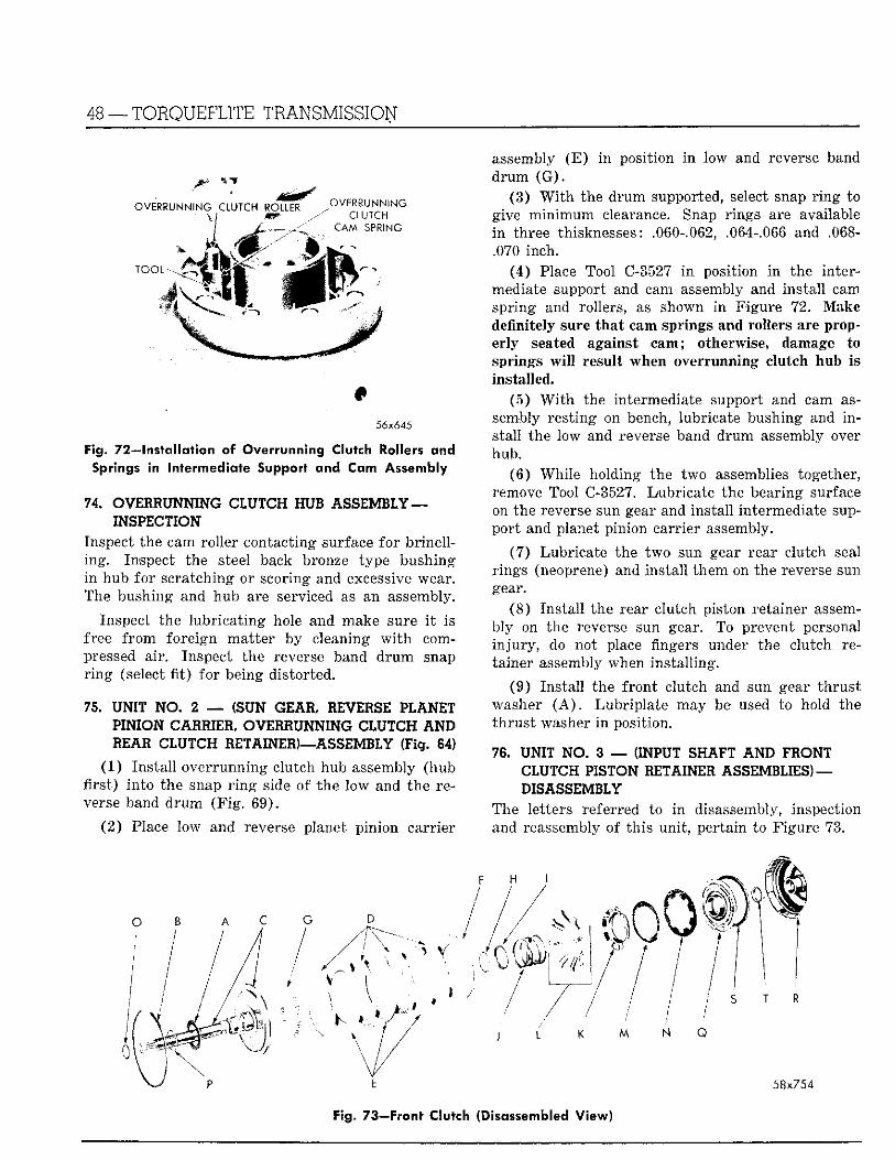
48 — TORQUEFLITE TRANSMISSION
mm
# 56x645
Fig. 72—Installation of Overrunning Clutch toilers and Springs in Intermediate Support and Cam Assembly
74. OVERRUNNING CLUTCH HUB ASSEMBLY— INSPECTION
Inspect the cam rol ler contacting surface fo r br ine l l ing . Inspect the steel back bronze type bushing i n hub fo r scratching or scoring and excessive wear. The bushing and hub are serviced as an assembly.
Inspect the lubr ica t ing hole and make sure i t is free f r o m fore ign mat te r by cleaning w i t h compressed air . Inspect the reverse band d r u m snap r i n g (select fit) fo r being distorted.
75. UNIT NO. 2 — (SUN GEAR. REVERSE PLANET PINION CARRIER, OVERRUNNING CLUTCH A N D REAR CLUTCH RETAINER)—ASSEMBLY (Fig. 84)
(1 ) Ins ta l l over running clutch hub assembly (hub first) Into the snap r i n g side of the low and the reverse band d r u m ( F i g . 69) .
( 2 ) Place low and reverse planet p inion carr ier
O B A C G D
assembly ( E ) i n position i n low and reverse band d r u m ( G ) .
(3) W i t h the d r u m supported, select snap r i n g to give m i n i m u m clearance. Snap r ings are available i n three thisknesses: .060-.062, .064-.066 and .068-.070 inch.
(4) Place Tool C-3527 i n position i n the intermediate support and cam assembly and insta l l cam spr ing and rollers, as shown i n Figure 72. Make definitely sure tha t cam springs and rollers are properly seated against cam; otherwise, damage to springs w i l l result when overrunning clutch hub Is installed.
(5) W i t h the intermediate support and cam assembly res t ing on bench, lubricate bushing and i n stall the low and reverse band d rum assembly over hub.
(6 ) Whi le holding the two assemblies together, remove Tool C-3527. Lubr ica te the bearing surface on the reverse sun gear and insta l l intermediate support and planet pinion carrier assembly.
(7) Lubricate the two sun gear rear clutch seal r ings (neoprene) and insta l l them on the reverse sun gear.
(8 ) Ins ta l l the rear clutch piston retainer assembly on the reverse sun gear. To prevent personal i n j u r y , do not place fingers under the clutch retainer assembly when ins ta l l ing.
(9 ) Ins ta l l the f ron t clutch and sun gear t h rus t washer ( A ) . Lubr ip la te may be used to hold the t h rus t washer i n position.
76. UNIT NO. 3 — (INPUT SHAFT AND FRONT CLUTCH PISTON RETAINER ASSEMBLIES) — DISASSEMBLY
The letters referred to i n disassembly, inspection and reassembly of th is uni t , per tain to Figure 73.
I K M N Q
58x754
Fig. 73—Front Clutch (Disassembled View)
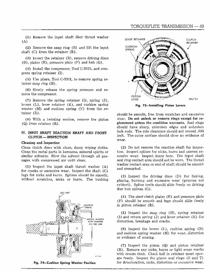
TORQUEFLITE TRANSMISSION — 49
(1 ) Remove the inpu t shaft fiber t h r u s t washer ( A )
(2 ) Remove the snap r i n g (B) and l i f t the input shaft (C) f r o m the retainer ( R ) .
(3 ) I nve r t the retainer ( R ) , remove d r i v i n g discs ( D ) , plates ( E ) , pressure plate (F ) and hub ( G ) .
(4 ) Ins ta l l the compressor, Tool C-3575, and compress spr ing retainer ( I ) .
(5 ) Use pliers, Tool C-3301, to remove spr ing retainer snap r i n g ( H ) .
(6 ) Slowly release the spr ing pressure and remove the compressor.
( 7 ) Remove the spr ing retainer ( I ) , spr ing ( J ) , levers ( L ) , lever retainer ( K ) , and cushion spr ing washer ( M ) and cushion spring ( N ) f r o m the retainer ( R ) .
(8 ) W i t h a t w i s t i n g motion, remove the piston (Q) f r o m retainer ( R ) .
77. INPUT SHAFT REACTION SHAFT AND FRONT CLUTCH — INSPECTION
Cleaning and Inspection Clean clutch discs w i t h clean, damp w i p i n g cloths. Clean the metal parts i n kerosene, minera l spir i ts or s imilar solvents. Blow the solvent th rough oil passages w i t h compressed a i r u n t i l clean.
(1 ) Inspect the input shaft t h rus t washer ( A ) fo r cracks or excessive wear. Inspect the shaft (C) lugs for nicks and burrs . Splines should be smooth, w i t h o u t scratches, nicks or burrs . The bushing
.020"-.040"
Fig. 74—Cushion Spring Washer Position
LEVER RETAINER CLUTCH \ RETAINER
CUSHION ' * / SPRING
PISTON
LEVER 58x753
Fig. 75—Installing Piston Levers
should be smooth, free f r o m scratches and excessive wear. Do not unlock or remove r ings except fo r replacement unless the condition warrants . Seal r ings should have sharp, unbroken edges and unbroken lock ends. The side clearance should not exceed .005 inch. The outer surface should show no evidence of wear.
( 2 ) Do not remove the reaction shaft for inspect ion . Inspect splines fo r nicks, burrs and uneven excessive wear. Inspect inner bore. The input shaft seal r i n g contact area should not be worn . The t h r u s t washer contact area on end of shaft should be smooth and unmarked.
(3 ) Inspect the d r i v i n g discs (D) for flaking, glazing, burn ing and excessive wear (grooves not evident) . Spline teeth should slide freely on d r i v i n g disc hub splines ( G ) .
( 4 ) The steel clutch plates (E ) and pressure plate ( F ) should be smooth and lugs should slide freely i n piston retainer ( R ) .
(5) Inspect the snap r i n g ( H ) , spr ing retainer ( I ) and r e tu rn spring (J) and lever retainer ( K ) fo r dis tor t ion, breakage and cracks.
( 6 ) Inspect the levers ( L ) , cushion spr ing ( N ) and cushion spring washer ( M ) for wear, d is tor t ion or evidence of scoring.
(7) Inspect the piston (Q) and piston retainer ( R ) . Remove any nicks, burrs or l i g h t score marks w i t h crocus cloth. Check ball i n retainer must operate freely. Inspect the piston seal r ings (S and T ) for deterioration, nicks, d is tor t ion or excessive wear.
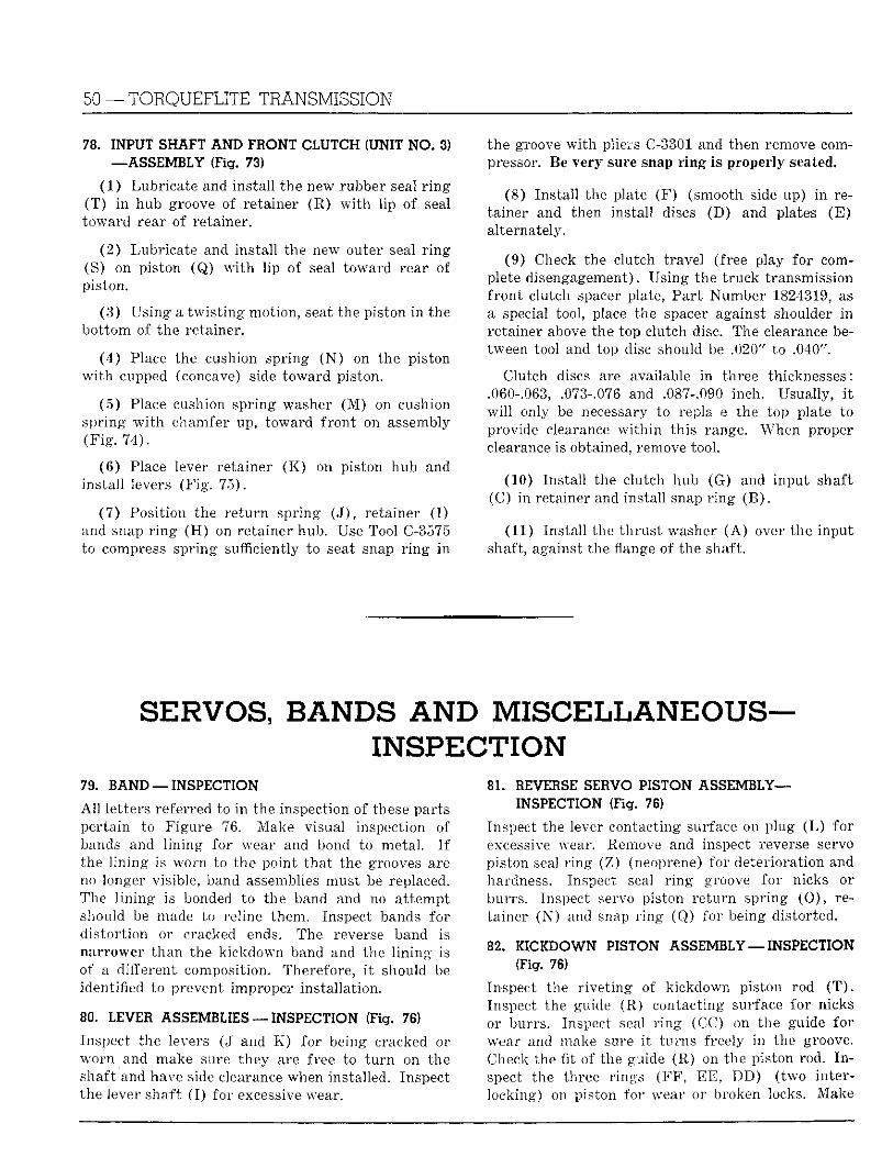
50 — T O R Q U E F L I T E T R A N S M I S S I O N
78. INPUT SHAFT AND FRONT CLUTCH (UNIT NO. 3) —ASSEMBLY (Fig. 73)
(1 ) Lubricate and instal l the new rubber seal r i n g ( T ) i n hub groove of retainer (R) w i t h l ip of seal toward rear of retainer.
(2 ) Lubricate and insta l l the new outer seal r i n g (S) on piston (Q) w i t h l ip of seal toward rear of piston.
(3) Us ing a t w i s t i n g motion, seat the piston i n the bo t tom of the retainer,
( 4 ) Place the cushion spring ( N ) on the piston w i t h cupped (concave) side toward piston.
(5 ) Place cushion spr ing washer ( M ) on cushion spr ing w i t h chamfer up, toward f ron t on assembly ( F i g . 74) .
(6 ) Place lever retainer ( K ) on piston hub and ins ta l l levers (F ig . 75) .
(7 ) Posit ion the r e tu rn spring ( J ) , retainer ( I ) and snap r i n g ( H ) on retainer hub. Use Tool C-3575 to compress spr ing sufficiently to seat snap r i n g i n
the groove w i t h pliers C-3301 and then remove compressor. Be very sure snap r i n g is properly seated.
(8) Ins ta l l the plate (F) (smooth side up) i n retainer and then instal l discs (D) and plates ( E ) alternately.
(9) Check the clutch t ravel (free play for complete disengagement). Us ing the t ruck transmission f ron t clutch spacer plate, Pa r t Number 1824319, as a special tool, place the spacer against shoulder i n retainer above the top clutch disc. The clearance between tool and top disc should be .020" to .040".
Clutch discs are available in three thicknesses: .060-.063, .073-.076 and .087-.090 inch. Usually, i t w i l l only be necessary to repla e the top plate to provide clearance w i t h i n th is range. When proper clearance is obtained, remove tool.
(10) Ins ta l l the clutch hub (G) and input shaft (C) i n retainer and instal l snap r i n g ( B ) .
(11) Instal l the th rus t washer ( A ) over the input shaft, against the flange of the shaft.
SERVOS, BANDS AND M I S C E L L A N E O U S -INSPECTION
79. BAND —INSPECTION
A l l letters referred to in the inspection of these parts per ta in to Figure 76. Make visual inspection of bands and l in ing for wear and bond to metal . I f the l i n i n g is worn to the point tha t the grooves are no longer visible, band assemblies must be replaced. The l i n ing is bonded to the band and no a t tempt should be made to reline them. Inspect bands for d is tor t ion or cracked ends. The reverse band is narrower than the k ickdown band and the l i n i n g is of a different composition. Therefore, i t should be identified to prevent improper instal lat ion.
80. LEVER ASSEMBLIES —INSPECTION (Fig. 76)
Inspect the levers (J and K ) for being cracked or worn and make sure they are free to t u r n on the shaft and have side clearance when installed. Inspect the lever shaft ( I ) for excessive wear.
81. REVERSE SERVO PISTON ASSEMBLY— -INSPECTION (Fig. 76)
Inspect the lever contacting surface on plug ( L ) fo r excessive wear. Remove and inspect reverse servo piston seal r i n g (Z) (neoprene) for deteriorat ion and hardness. Inspect seal r i n g groove for nicks . or burrs . Inspect servo piston re tu rn spring (O) , retainer ( N ) and snap r i n g (Q) for being distorted.
82. KICKDOWN PISTON ASSEMBLY — INSPECTION (Fig. 76)
Inspect the r ive t ing of kickdown piston rod ( T ) . Inspect the guide (R) contacting surface for nicks or burrs. Inspect seal r i n g (CC) on the guide for wear and make sure i t turns freely i n the groove. Check the fit of the guide (R) on the piston rod. I n spect the three r ings (FF , EE , D D ) ( two interlocking) on piston for wear or broken locks. Make
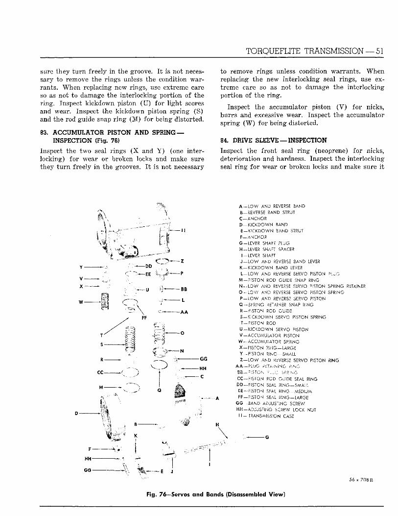
sure they t u r n freely i n the groove. I t is not necessary to remove the r ings unless the condition warrants. When replacing new rings, use extreme care so as not to damage the inter locking por t ion of the r i ng . Inspect k ickdown piston ( U ) for l i g h t scores and wear. Inspect the kickdown piston spr ing (S) and the rod guide snap r i n g ( M ) fo r being distorted.
88. ACCUMULATOR PISTON A N D SPRING — INSPECTION (Fig. 78)
Inspect the t w o seal r ings ( X and Y ) (one interlocking) fo r wear or broken locks and make sure they t u r n freely In the grooves. I t Is not necessary
TORQUEFLITE TRANSMISSION — 51
to remove r ings unless condition warrants . When replacing the new Inter locking seal r ings, use extreme care so as not to damage the Inter locking por t ion of the r i n g .
Inspect the accumulator piston ( V ) for nicks, burrs and excessive wear. Inspect the accumulator spr ing ( W ) for being distorted.
84. DRIVE SLEEVE —INSPECTION
Inspect the f ron t seal r i n g (neoprene) for nicks, deteriorat ion and hardness. Inspect the in ter locking seal r i n g fo r wear or broken locks and make sure I t
v-x-
DD
" — E E
f l -
CC-
- Z
- P
- B B
~L
- G G
-HH
- C
A—LOW AND REVERSE BAND B—REVERSE BAND STRUT C-ANCHOi D—KICKDOWN BAND E—KICKDOWN BAND STRUT F—ANCHOR G —LEVER SHAFT PLUG H-LEVER SHAFT SPACER I —LEVER SHAFT J - L O W AND REVERSE BAND LEVER K - KICKDOWN BAND LEVER L - L O W AND REVERSE SERVO PISTON ' P L U G
M —PISTON ROD GUIDE SNAP RING N - l O W AND REVERSE SERVO PISTON SPRING RETAINER O - L O W AND REVERSE SERVO PISTON SPRING P - L O W AND REVERSE SERVO PISTON Q-SPRING RETAINER SNAP RING R-PISTON ROD GUIDE S-KICKDOWN SERVO PISTON SPRING T-PISTON ROD U-KICKDOWN SERVO PISTON V—ACCUMULATOR PISTON W—ACCUMULATOR SPRING X-PSSTON RING-LARGE Y-PISTON RING-SMALL Z - L O W A N D -REVERSE SERVO PISTON RING
,4 A — 5 L '"-J C A £7 A, s'% ,* N* G ,! -v "7
CC-?;$70N ROD GUOc SEAL R!NG D D —PISTON' SEAL K'NG—SMALL £ £ - - ? ; S T O N SEAL RiNG — MzDiUM r r —PISTON SEAL R I N G — L A R G E
S3-BAND ADJUSTING SCREW -ADJUSTING SCREW LOCK NUT
\ t — TRANSMISSION CASE
F-
H H -
G G -
56 x 708B Fig. 76—Servos and Bands (Disassembled View)
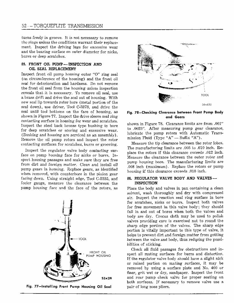
52 — T O R Q U E F L I T E T R A N S M I S S I O N
turns freely i n groove. I t is not necessary to remove the r ings unless the conditions wa r r an t the i r replacement. Inspect the d r i v i n g lugs fo r excessive wear and the bearing surface on outer diameter fo r nicks, burrs or deep scratches.
85. F I O N T OIL PUMP—INSPECTION A N D OIL SEAL REPLACEMENT
Inspect f ron t o i l pump housing outer " 0 " r i n g seal (on circumference of the housing) and the f ron t o i l seal fo r deterioration and hardness. Do not remove the f ron t oi l seal f r o m the housing unless inspection reveals tha t i t is necessary. To remove o i l seal, use a brass d r i f t and dr ive the seal out of housing. W i t h new seal l ip towards ro tor bore (metal por t ion of the seal down) , use driver, Tool C-3278, and dr ive the seal un t i l tool bottoms on the face of housing, as shown i n F igure 77. Inspect the dr ive sleeve seal r i n g contacting surface i n housing for wear and scratches. Inspect the steel back bronze type bushing i n bore for deep scratches or scoring and excessive wear. (Bushing and housing are serviced as an assembly). Remove the oi l pump rotors and inspect the ro tor contacting surfaces for scratches, burrs or grooving.
Inspect the regulator valve body contacting surface on pump housing face fo r nicks or burrs . I n spect housing passages and make sure they are free f r o m d i r t and fore ign mat ter . Clean and insta l l oi l pump gears i n housing. Replace gears, as identified when removed, w i t h counterbore i n the pinion gear facing down. Us ing s t ra igh t edge, Tool C-3335, and feeler gauge, measure the clearance between the pump housing face and the face of the rotors, as
.' o - I D O L
"RONT O i l PL'.-AP. H O U S I N G
~ ™ 53x28
Fig. 77—Installing Front Pump Housing Oil Seal
•• ' .^^^^^^^m^^^ T O O L
56x650
Fig. 78—Checking Clearance between front Pump Body and Gears
shown i n Figure 78. Clearance l imi t s are f r o m .001" to .0025". A f t e r measuring pump gear clearance, lubricate the pump rotors w i t h Automat ic Transmission F l u i d (Type " A " —Suf f ix " A " ) .
Measure the t i p clearance between the ro tor lobes. The manufac tur ing l imi t s are .005 to .010 inch. Replace the rotors i f this clearance exceeds ,,012 inch. Measure the clearance between the outer ro tor and pump housing bore. The manufactur ing l im i t s are .008 inch ( m a x i m u m ) . Replace the rotors or pump housing i f th is clearance exceeds .010 inch.
86. REGULATOR VALVE BODY AND VALVES — INSPECTION
Place the body and valves i n pan containing a clean solvent, wash thoroughly and dry w i t h compressed air. Inspect the reaction seal r i n g surface i n bore for scratches, nicks or burrs . Inspect both valves for free movement i n th is valve body; they should fa l l i n and out of bores when both the valves and body are d ry . Crocus cloth may be used to polish valves provid ing care is exercised not to round the sharp edge por t ion of the valves. The sharp edge port ion is v i t a l l y impor tan t to th is type of valve, i t helps to prevent d i r t and foreign mat ter f r o m ge t t ing between the valve and body, thus reducing the possibil i t ies of s t icking.
Check a l l fluid passages for obstructions and i n spect al l m a t i n g surfaces for burrs and d is tor t ion . I f the regulator valve body should have a s l ight nick or raised por t ion on ma t ing surfaces, i t may be removed by using a surface plate and No. 400 or finer, g r i t wet or dry , sandpaper. Inspect the f r o n t and rear pump check valve for proper seating on both surfaces. I f necessary to remove valve use a pair of long nose pliers.
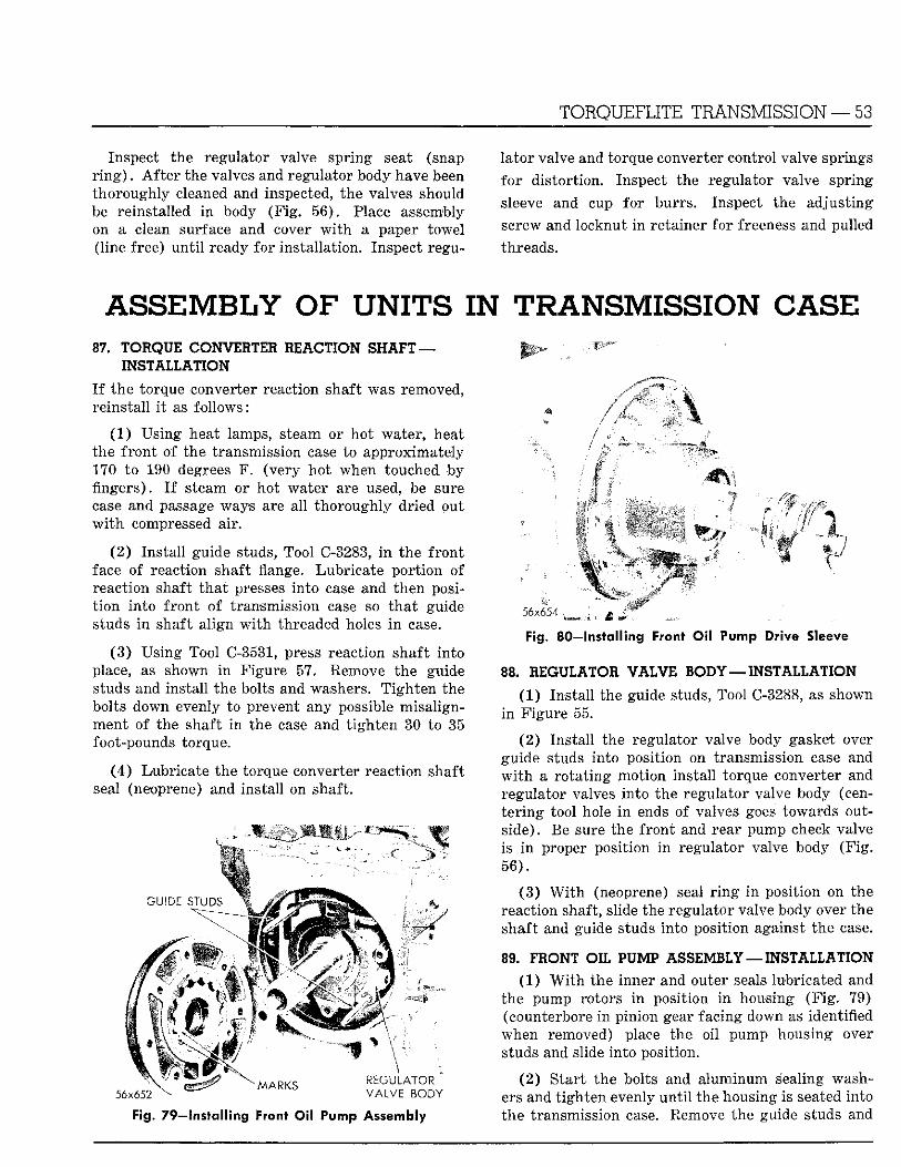
TORQUEFLITE TRANSMISSION — 53
Inspect the regulator valve spring seat (snap r i n g ) . A f t e r the valves and regulator body have been thoroughly cleaned and inspected, the valves should be reinstalled i n body (F ig . 56) . Place assembly on a clean surface and cover w i t h a paper towel (line free) u n t i l ready for instal lat ion. Inspect regu
la tor valve and torque converter control valve springs
f o r d is tor t ion. Inspect the regulator valve spring
sleeve and cup for burrs . Inspect the adjust ing
screw and locknut i n retainer for freeness and pulled
threads.
ASSEMBLY OF UNITS IN TRANSMISSION C A S E 87. TORQUE CONVERTER REACTION SHAFT —
INSTALLATION
I f the torque converter reaction shaft was removed, reinstal l i t as fol lows:
(1) Using heat lamps, steam or hot water, heat the f ron t o f the transmission case to approximately 170 to 190 degrees F . (very ho t when touched by fingers). I f steam or hot water are used, be sure case and passage ways are al l thoroughly dr ied out w i t h compressed air.
(2 ) Ins ta l l guide studs, Tool C-3283, i n the f ron t face of reaction shaft flange. Lubr ica te por t ion of reaction shaft t ha t presses in to case and then posit i on in to f ron t of transmission case so t h a t guide studs i n shaft a l ign w i t h threaded holes i n case.
(3 ) Using Tool C-3531, press reaction shaft in to place, as shown i n Figure 57. Remove the guide studs and instal l the bolts and washers. T igh ten the bolts down evenly to prevent any possible misal ignment of the shaft i n the case and t i gh ten 30 to 35 foot-pounds torque.
( 4 ) Lubr ica te the torque converter reaction shaft seal (neoprene) and instal l on shaft.
GUIDE STUDS
M A R K S V A L V E BODY 56x652 -
Fig. 79—Installing Front Oil Pump Assembly
Fig. 80—Installing Front Oil Pump Drive Sleeve
88. REGULATOR VALVE BODY—INSTALLATION
(1 ) Ins ta l l the guide studs, Tool C-3288, as shown i n F igure 55.
(2 ) Ins ta l l the regulator valve body gasket over guide studs into position on transmission case and w i t h a ro t a t ing mot ion insta l l torque converter and regulator valves into the regulator valve body (cent e r ing tool hole i n ends of valves goes towards outside) . Be sure the f ron t and rear pump check valve is i n proper posit ion i n regulator valve body ( F i g . 56) .
( 3 ) W i t h (neoprene) seal r i n g i n position on the reaction shaft, slide the regulator valve body over the shaft and guide studs into posit ion against the case.
89. FRONT OIL PUMP ASSEMBLY — INSTALLATION
(1) W i t h the inner and outer seals lubricated and the pump rotors i n position i n housing (F ig . 79) (counterbore i n pinion gear facing down as identified when removed) place the oil pump housing over studs and slide in to position.
(2 ) Star t the bolts and a luminum sealing washers and t igh ten evenly u n t i l the housing is seated into the transmission case. Remove the guide studs and
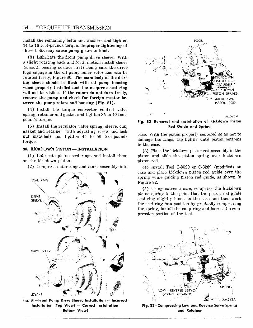
54 —TORQUEFLITE TRANSMISSION
Instal l the remaining bolts and washers and t igh ten 14 to 16 foot-pounds torque. Improper t igh ten ing of these bolts may cause pump gears to b ind .
(3 ) Lubricate the f ron t pump dr ive sleeve. W i t h a s l ight ro t a t i ng back and f o r t h mot ion ins ta l l sleeve (smooth bearing surface f i r s t ) being sure the d r ive lugs engage i n the oi l pump inner ro to r and can be rotated freely, Figure 80. The main body of the d r iv i n g sleeve should be l u s h w i t h o i l pump housing when properly installed and the neoprene seal r i n g w i l l not be visible. I f the rotors do no t t u r n freely, remove the pump and check f o r fore ign mat te r between the pump rotors and housing ( F i g . 81 ) .
( 4 ) Ins ta l l the torque converter control valve spring, retainer and gasket and t i g h t e n 35 to 40 footpounds torque.
(5 ) Ins t a l l the regulator valve spring, sleeve, cup, gasket and retainer ( w i t h adjus t ing screw and lock n u t installed) and t igh ten 45 to 50 foot-pounds torque.
90. KICKDOWN PISTON — I N S T A L L A T I O N
( 1 ) Lubricate piston seal r ings and ins ta l l them on the k ickdown piston.
( 2 ) Compress outer r i n g and s tar t assembly into
TOOL
SEAL RING
DRIVE SLEEVE
IS
mm
mmWm\
DRIVE SLEEVE ;
\
Fig. 81—Front Pump Drive Sleeve Installation — Incorrect Installation (Top View) — Correct Installation
(Bottom; View)
K I C K D O W N PISTON ROD
KfaCDOWN PISTON SPRING
— - K I C K D O W N PISTON ROD
56x625 A
Fig. 82—Removal and Installation of Kickdown Piston Rod Guide and Spring
case. W i t h the piston properly centered so as not to damage the rings, tap l i g h t l y u n t i l piston bottoms i n the case.
( 3 ) Place the k ickdown piston rod assembly i n the piston and slide the piston spr ing over k ickdown piston rod.
(4) Ins ta l l Tool C-3529 or C-3289 (modified) on case and place kickdown piston rod guide over the spring whi le guiding piston rod guide, as shown i n Figure 82.
(5) Us ing extreme care, compress the k ickdown piston spr ing to the point t ha t the piston rod guide seal r i n g s l igh t ly binds on the case and then w o r k the seal r i n g into position by gradually compressing the spring, instal l the snap r i n g and loosen the compression por t ion of the tool.
T O O L
L O W - R E V E R S E SERVO' S P R I N G RETAINER ' ;
56x623A
Fig. 83—Compressing Low and Reverse Servo Spring and Retainer
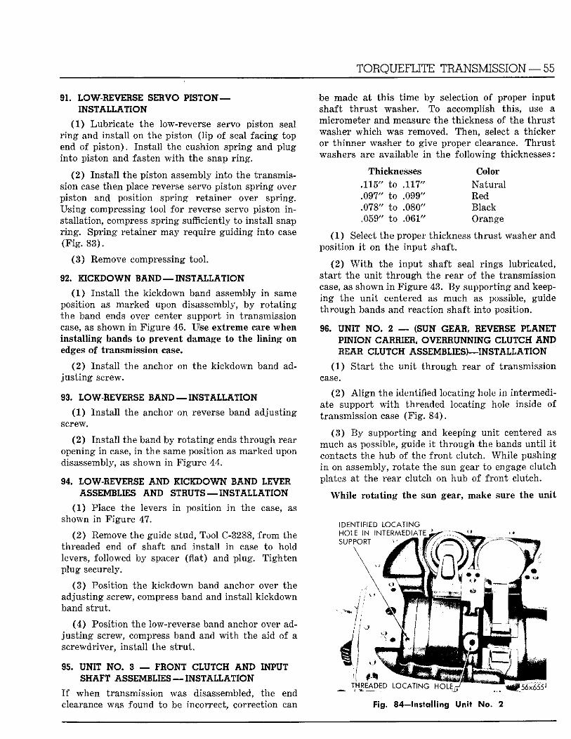
TORQUEFLITE TRANSMISSION — 55
9L LOW-REVERSE SERVO PISTON — INSTALLATION
(1 ) Lubr ica te the low-reverse servo pis ton seal r i n g and ins ta l l on the piston ( l ip of seal facing top end of p i s ton) . Ins ta l l the cushion spr ing and plug in to piston and fasten w i t h the snap r i n g .
( 2 ) Ins ta l l the piston assembly in to the transmission case then place reverse servo piston spr ing over piston and position spring retainer over spring. Using compressing tool fo r reverse servo piston i n stallation, compress spr ing sufficiently to instal l snap r i n g . Spr ing retainer may require guid ing into case (F ig . 83) .
( 3 ) Remove compressing tool .
92, KICKDOWN BAND — INSTALLATION
(1) Ins ta l l the k ickdown band assembly i n same position as marked upon disassembly, by ro t a t i ng the band ends over center support i n transmission case, as shown i n F igure 46. Use extreme care when ins ta l l ing bands to prevent damage to the l i n ing on edges of transmission case.
(2 ) Ins ta l l the anchor on the k ickdown band adj u s t i n g screw.
9 3 . LOW-REVERSE BAND — INSTALLATION
(1) Ins ta l l the anchor on reverse band adjust ing screw.
(2 ) Ins ta l l the band by r o t a t i n g ends th rough rear opening i n case, i n the same posit ion as marked upon disassembly, as shown i n F igure 44.
94 LOW-REVERSE A N D KICKDOWN BAND LEVER ASSEMBLIES AND STRUTS — INSTALLATION
(1) Place the levers i n posit ion i n the case, as shown i n F igure 47.
( 2 ) Remove the guide stud, Tool C-3288, f r o m the threaded end of shaft and ins ta l l i n case to hold levers, followed by spacer (f lat) and plug. T igh ten p lug securely.
( 3 ) Position the k ickdown band anchor over the adjust ing screw, compress band and instal l k ickdown band s t ru t .
( 4 ) Posit ion the low-reverse band anchor over adj u s t i n g screw, compress band and w i t h the aid of a screwdriver, ins ta l l the s t ru t .
95. UNIT N O . 3 — FRONT CLUTCH A N D INPUT SHAFT ASSEMBLIES — INSTALLATION
I f when transmission was disassembled, the end clearance was found to be incorrect, correction can
be made at th i s t ime by selection of proper input shaft t h ru s t washer. To accomplish this , use a micrometer and measure the thickness of the t h rus t washer wh ich was removed. Then, select a th icker or th inner washer to give proper clearance. Thrus t washers are available i n the fo l lowing thicknesses:
Thicknesses Color .115" to .117" Na tu ra l .097" to .099" Red .078" to .080" Black .059" to .061" Orange
(1 ) Select the proper thickness t h rus t washer and posit ion i t on the inpu t shaft.
(2 ) W i t h the inpu t shaft seal r ings lubricated, s tar t the un i t t h rough the rear of the transmission case, as shown i n F igure 43. By support ing and keeping the u n i t centered as much as possible, guide th rough bands and reaction shaft in to position.
96. UNIT NO. 2 — (SUN GEAR, REVERSE PLANET PINION CARRIER, OVERRUNNING CLUTCH AND REAR CLUTCH ASSEMBLIES)—INSTALLATION
(1) S ta r t the un i t t h rough rear of transmission case.
(2 ) A l i g n the identified locating hole i n intermediate support w i t h threaded locating hole inside of transmission case ( F i g . 84) .
(3 ) B y support ing and keeping un i t centered as much as possible, guide i t t h rough the bands u n t i l i t contacts the hub of the f ron t clutch. Whi le pushing i n on assembly, rotate the sun gear to engage clutch plates at the rear clutch on hub of f ron t clutch.
Whi le r o t a t i n g the sun gear, make sure the un i t
IDENTIFIED L O C A T I N G
Fig. 84- lnsta l l ing Unit No. 2
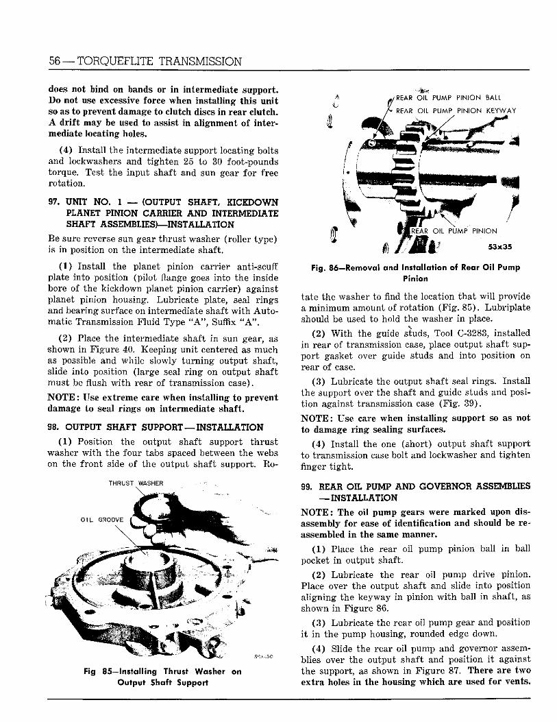
56 —TORQUEFLITE TRANSMISSION
does not bind on bands or i n intermediate support. B o not use excessive force when ins ta l l ing th is un i t so as to prevent damage to clutch discs i n rear c lutch. A d r i f t may be used to assist i n al ignment of intermediate locat ing holes.
(4) Ins ta l l the intermediate support locating bolts and lockwashers and t i gh t en 25 to 30 foot-pounds torque. Test the input shaft and sun gear fo r free rota t ion.
97. UNIT NO. 1 — (OUTPUT SHAFT, K I C I D O W N PLANET PINION GABBIER A N D INTEBMEDIATE SHAFT ASSEMBLIES)—-INSTALLATION
Be sure reverse sun gear t h rus t washer (roller type) is i n position on the intermediate shaft.
(1) Ins ta l l the planet pinion carrier anti-scuff plate into posit ion (pi lo t flange goes into the inside bore of the kickdown planet pinion carr ier) against planet pinion housing. Lubr ica te plate, seal r ings and bearing surface on intermediate shaft w i t h A u t o mat ic Transmission F l u i d Type " A " , Suffix " A " .
(2 ) Place the intermediate shaft i n sun gear, as shown i n F igure 40. Keeping un i t centered as much as possible and whi le slowly t u r n i n g output shaft, slide into posi t ion (large seal r i n g on output shaft must be flush w i t h rear of transmission case).
N O T E : Use extreme care when ins ta l l ing to prevent damage to seal r ings on intermediate shaft.
9 8 . OUTPUT SHAFT SUPPOBT — INST ALL A T I O N
(1) Posit ion the output shaft support t h r u s t washer w i t h the four tabs spaced between the webs on the f ron t side of the output shaft support. Ro-
THRUST WASHER
Fig 85—Installing Thrust Washer on Output Shaft Support
Fig. 86—Removal and Installation of Rear Oil Pump Pinion
tate the washer to find the location tha t w i l l provide a m i n i m u m amount of ro ta t ion ( F i g . 85) . Lubr ip la te should be used to hold the washer i n place.
(2 ) W i t h the guide studs, Tool C-3283, installed i n rear of transmission case, place output shaft suppor t gasket over guide studs and in to position on rear of case.
(3 ) Lubricate the output shaft seal r ings. Ins ta l l the support over the shaft and guide studs and posit i on against transmission case (F ig . 39) .
N O T E : Use care when ins ta l l ing support so as not to damage r i n g sealing surfaces.
(4 ) Ins ta l l the one (short) output shaft support to transmission case bolt and lockwasher and t igh ten finger t i g h t .
99. BEAB OIL PUMP A N D GOVERNOB ASSEMBLIES — INSTALLATION
N O T E : The o i l pump gears were marked upon disassembly for ease of identification and should be reassembled i n the same manner.
(1) Place the rear o i l pump pinion ball i n ball pocket i n output shaft.
( 2 ) Lubr ica te the rear oil pump drive pinion. Place over the output shaft and slide into posit ion a l igning the keyway i n pinion w i t h ball i n shaft, as shown i n Figure 86.
(3 ) Lubr ica te the rear oi l pump gear and position i t i n the pump housing, rounded edge down.
(4 ) Slide the rear oi l pump and governor assemblies over the output shaft and posit ion i t against the support, as shown i n F igure 87. There are two ex t ra holes i n the housing which are used for vents.
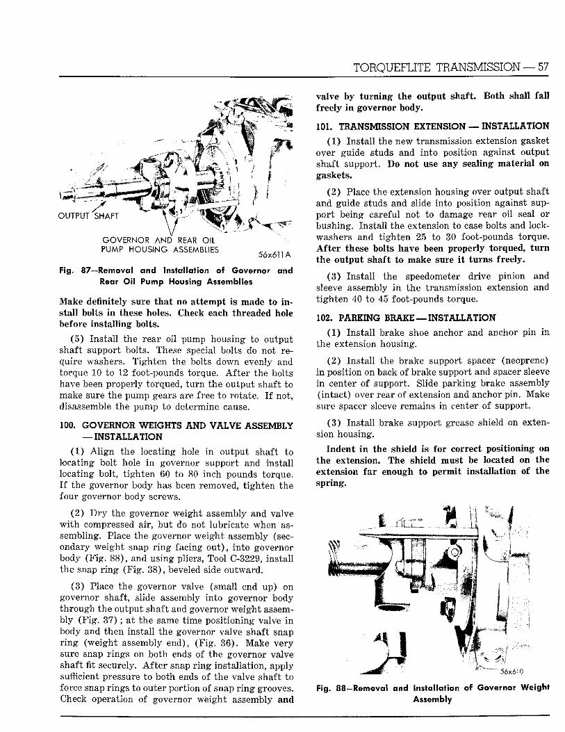
TORQUEFLITE TRANSMISSION — 57
valve by t u r n i n g the output shaft. freely i n governor b o i y .
Bo th shall f a l l
O U T P U T S H A F T
G O V E R N O R A N D REAR O I L P U M P H O U S I N G A S S E M B L I E S
56x611 A
Fig. 87—Removal and Installation of Governor and Rear Oil Pump Housing Assemblies
Make definitely sure t h a t no a t tempt is made to i n stal l bolts i n these holes. Check each threaded hole before ins ta l l ing bolts.
(5 ) Ins ta l l the rear oi l pump housing to output shaft support bolts. These special bolts do not require washers. T igh ten the bolts down evenly and torque 10 to 12 foot-pounds torque. A f t e r the bolts have been properly torqued, t u r n the output shaft to make sure the pump gears are free to rotate. I f not, disassemble the pump to determine cause.
100. G O V E B N O l WEIGHTS A N D VALVE ASSEMBLY — INSTALLATION
(1) A l i g n the locating hole i n output shaft to locating bolt hole i n governor support and ins ta l l locating bolt, t i gh ten 60 to 80 inch pounds torque. I f the governor body has been removed, t igh ten the four governor body screws.
(2 ) D r y the governor weight assembly and valve w i t h compressed air, bu t do not lubricate when assembling. Place the governor weigh t assembly (secondary weigh t snap r i n g facing o u t ) , in to governor body (F ig . 88) , and using pliers, Tool C-3229, ins ta l l the snap r i n g (F ig . 38) , beveled side ou tward .
(3 ) Place the governor valve (small end up) on governor shaft, slide assembly in to governor body th rough the output shaft and governor we igh t assembly (F ig . 3 7 ) ; at the same t ime posi t ioning valve i n body and then insta l l the governor valve shaft snap r i n g (weight assembly end), (F ig . 36) . Make very sure snap r ings on bo th ends of the governor valve shaft fit securely. A f t e r snap r i n g instal lat ion, apply sufficient pressure to both ends of the valve shaft to force snap rings to outer port ion of snap r i n g grooves. Check operation of governor weight assembly and
.101. TBANSMISSION EXTENSION — INSTALLATION
(1) Ins ta l l the new transmission extension gasket over guide studs and in to position against output shaft support. Do not use any sealing mater ia l on gaskets.
( 2 ) Place the extension housing over output shaft and guide studs and slide into posit ion against suppor t being careful not to damage rear oi l seal or bushing. Ins ta l l the extension to case bolts and lockwashers and t igh ten 25 to 30 foot-pounds torque. A f t e r these bolts have been properly torqued, t u r n the output shaft to make sure i t tu rns freely.
(3 ) Ins ta l l the speedometer dr ive pinion and sleeve assembly i n the transmission extension and t igh ten 40 to 45 foot-pounds torque.
102. P A B I I N G BBA1E — INSTALLATION
(1) Ins ta l l brake shoe anchor and anchor p in i n the extension housing.
( 2 ) Ins ta l l the brake support spacer (neoprene) i n posit ion on back of brake support and spacer sleeve i n center of support. Slide pa rk ing brake assembly ( in tac t ) over rear of extension and anchor p in . Make sure spacer sleeve remains in center of support.
( 3 ) Ins ta l l brake support grease shield on extension housing.
Indent i n the shield is for correct posit ioning on the extension. The shield must be located on the extension fa r enough to permit ins ta l la t ion of the spr ing.
5 6 x 6 1 0
Fig. 88—Removal and Installation of Governor Weight Assembly
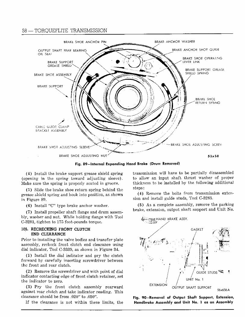
58 — TORQUEFLITE TRANSMISSION
BRAKE SHOE ANCHOR PIN ^ BRAKE ANCHOR WASHER
Fig. 89—Internal Expanding Hand Brake (Drum Removed)
(4 ) Ins ta l l the brake support grease shield spr ing (opening i n the spr ing toward adjus t ing sleeve). Make sure the spr ing is properly seated i n groove.
(5 ) Slide the brake shoe r e t u r n spr ing behind the grease shield spr ing and hook in to position, as shown i n F igure 89.
( 6 ) Ins ta l l "C" type brake anchor washer.
(7 ) Ins ta l l propeller shaft flange and d r u m assembly, washer and nut . Whi le holding flange w i t h Tool C-3281, t i gh t en to 175 foot-pounds torque.
103. HECHECIING FBONT CLUTCH END CLEA1ANCE
Pr io r to ins ta l l ing the valve bodies and t ransfer plate assembly, recheck f ron t clutch end clearance using dial indicator, Tool C-3339, as shown i n F igure 34.
(1) Ins ta l l the dial indicator and p r y the clutch f o r w a r d by carefully inser t ing screwdriver between the f r o n t and rear clutch.
(2 ) Remove the screwdriver and w i t h point of dial indicator contacting edge of f ron t clutch retainer, set the indicator to zero.
(3 ) P r y the f r o n t clutch assembly rea rward against rear clutch and take indicator reading. This clearance should be f r o m .020" to .050".
I f the clearance is not w i t h i n these l im i t s , the
transmission w i l l have to be par t ia l ly disassembled to allow an input shaft t h rus t washer of proper thickness to be installed by the fo l lowing additional steps:
(4 ) Remove the bolts f r o m transmission extension and instal l guide studs, Tool C-3283.
(5 ) As a complete assembly, remove the park ing brake, extension, output shaft support and U n i t No.
HAND BRAKE ASSY .
OUTPUT SHAFT S U P P O R T o6x6.56A
Fig. 90—Removal of Output Shaft Support, Extension, Handbrake Assembly and Unit No. 1 as an Assembly
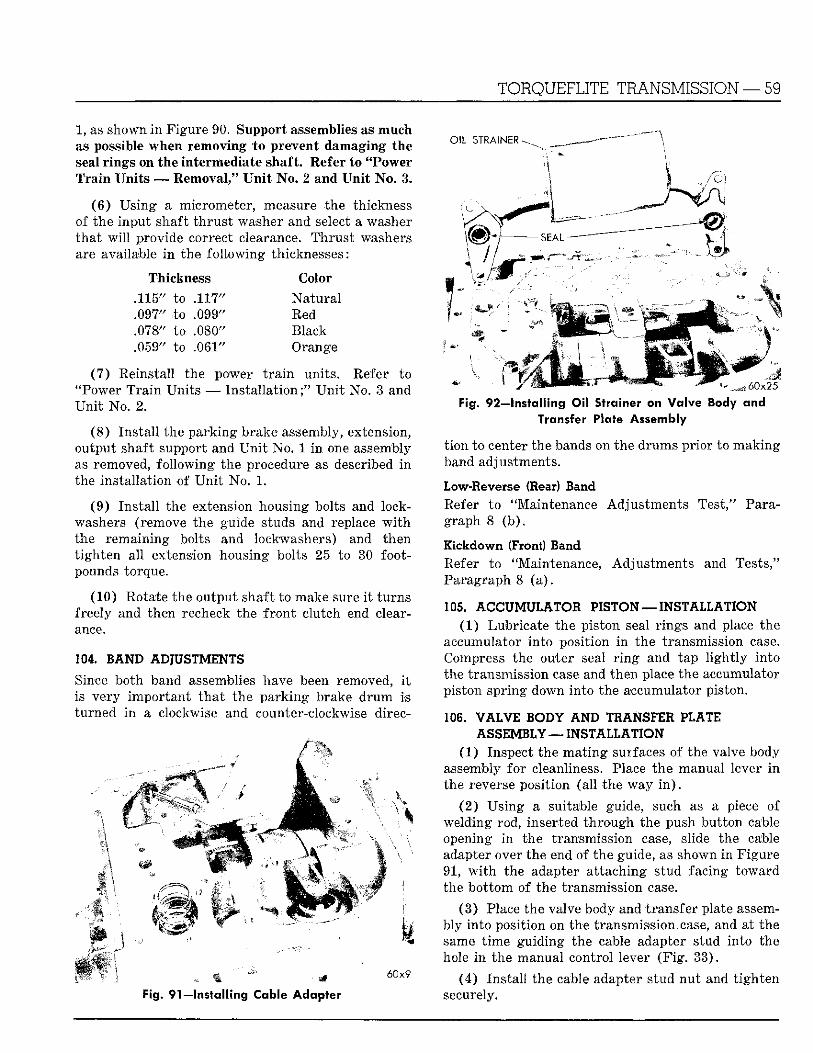
1, as shown i n Figure 90. Support assemblies as much as possible when removing to prevent damaging the seal r ings on the intermediate shaft. Refer to "Power T r a i n Un i t s — Removal," U n i t No . 2 and U n i t No . 3.
( 6 ) Us ing a micrometer, measure the thickness of the input shaft t h ru s t washer and select a washer t ha t w i l l provide correct clearance. Th rus t washers are available i n the fo l lowing thicknesses:
Thickness Color
.116" to .117" N a t u r a l
.097" to .099" Red
.078" to .080" Black
.059" to .061" Orange
(7 ) Reinstall the power t r a i n units . Refer to "Power T r a i n Uni t s — Ins ta l l a t ion ; " U n i t No. 3 and U n i t No. 2.
( 8 ) Ins ta l l the pa rk ing brake assembly, extension, output shaft support and U n i t No. 1 i n one assembly as removed, fo l lowing the procedure as described i n the ins ta l la t ion of U n i t No. 1.
(9) Ins ta l l the extension housing bolts and lockwashers (remove the guide studs and replace w i t h the remaining bolts and lockwashers) and then t igh ten a l l extension housing bolts 25 to 30 footpounds torque.
(10) Rotate the output shaft to make sure i t tu rns freely and then recheck the f r o n t clutch end clearance.
104. BAND ADJUSTMENTS
Since both band assemblies have been removed, i t is very impor tan t t h a t the pa rk ing brake d r u m is turned i n a clockwise and counter-clockwise direc-
•4 60x9
Fig. 91—Installing Cable Adapter
T O R Q U E F L I T E T R A N S M I S S I O N — 59
Fig. 92—Installing Oil Strainer on Va lve Body and Transfer Plate Assembly
t i on to center the bands on the drums pr ior to mak ing band adjustments.
Low-Reverse (Rear) Band Refer to ' 'Maintenance Adjus tments Test," Paragraph 8 ( b ) .
Kickdown (Front) Band Refer to "Maintenance, Adjus tments and Tests," Paragraph 8 (a ) .
105. ACCUMULATOR PISTON — INSTALLATION (1 ) Lubricate the pis ton seal r ings and place the
accumulator in to posit ion i n the transmission case. Compress the outer seal r i n g and tap l i g h t l y in to the transmission case and then place the accumulator piston spr ing down in to the accumulator piston.
106. VALVE BODY A N D TRANSFER PLATE ASSEMBLY — INSTALLATION
(1) Inspect the ma t ing surfaces of the valve body assembly for cleanliness. Place the manual lever i n the reverse posit ion (a l l the way i n ) .
(2 ) Us ing a suitable guide, such as a piece of welding rod, inserted t h rough the push but ton cable opening i n the transmission case, slide the cable adapter over the end o f the guide, as shown i n F igure 91, w i t h the adapter a t taching stud facing toward the bo t tom of the transmission case.
(3 ) Place the valve body and t ransfer plate assembly in to position on the transmission case, and at the same t ime guid ing the cable adapter stud into the hole i n the manual control lever (F ig . 33) .
(4) Ins ta l l the cable adapter s tud nu t and t igh ten securely.
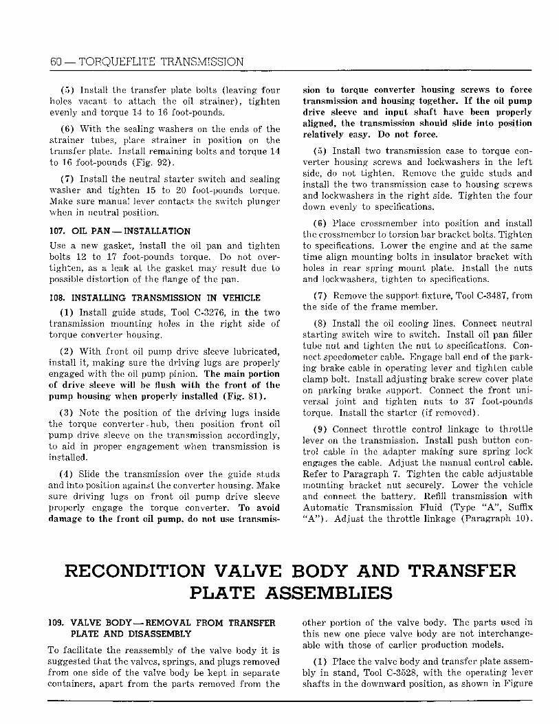
60 — TORQUEFLITE TRANSMISSION
(5 ) Ins ta l l the transfer plate bolts (leaving four holes vacant to attach the oi l s t ra iner ) , t i gh ten evenly and torque 14 to 16 foot-pounds.
(6 ) W i t h the sealing washers on the ends of the strainer tubes, place strainer i n position on the t ransfer plate. Ins ta l l remaining bolts and torque 14 to 16 foot-pounds (F ig . 92) .
(7 ) Ins ta l l the neutral s tarter switch and sealing washer and t igh ten 15 to 20 foot-pounds torque. Make sure manual lever contacts the switch plunger when i n neutral position.
107. OIL PAN —INSTALLATION
Use a new gasket, instal l the oil pan and t i gh t en bolts 12 to 17 foot-pounds torque. Do not overt igh ten , as a leak at the gasket may result due to possible dis tor t ion of the flange of the pan.
108. INSTALLING TRANSMISSION IN VEHICLE
(1 ) Ins ta l l guide studs, Tool C-3276, i n the two transmission mount ing holes i n the r i g h t side of torque converter housing.
(2 ) W i t h f ron t oi l pump drive sleeve lubricated, ins ta l l i t , mak ing sure the d r iv ing lugs are properly engaged w i t h the oil pump pinion. The main por t ion of dr ive sleeve w i l l be l u s h w i t h the f ron t of the pump housing when properly installed ( F i g . 81 ) .
(3 ) Note the position of the d r i v i n g lugs inside the torque converter-hub, then position f r o n t o i l pump drive sleeve on the transmission accordingly, to aid in proper engagement when transmission is installed.
(4 ) Slide the transmission over the guide studs and into position against the converter housing. Make sure d r iv ing lugs on f ron t oi l pump drive sleeve properly engage the torque converter. To avoid damage to the f ron t o i l pump, do not use t ransmis
sion to torque converter housing screws to force transmission and housing together. I f the o i l pump drive sleeve and input shaft have been properly aligned, the transmission should slide in to position relat ively easy. Do not force.
( 5 ) Ins ta l l two transmission case to torque converter housing screws and lockwashers i n the left side, do not t ighten . Remove the guide studs and instal l the two transmission case to housing screws and lockwashers i n the r i g h t side. T ighten the four down evenly to specifications.
(6) Place crossmember into position and instal l the crossmember to torsion bar bracket bolts. T igh ten to specifications. Lower the engine and at the same t ime al ign mount ing bolts i n insulator bracket w i t h holes i n rear spring mount plate. Ins ta l l the nuts and lockwashers, t igh ten to specifications.
(7 ) Remove the support fixture, Tool C-3487, f r o m the side of the frame member.
(8) Ins ta l l the oi l cooling lines. Connect neutral s t a r t ing switch wire to switch. Ins ta l l oi l pan filler tube nut and t igh ten the nut to specifications. Connect speedometer cable. Engage ball end of the parking brake cable in operating lever and t igh ten cable clamp bolt. Ins ta l l adjust ing brake screw cover plate on pa rk ing brake support. Connect the f ron t universal j o i n t and t igh ten nuts to 37 foot-pounds torque. Ins ta l l the starter ( i f removed).
(9 ) Connect th ro t t l e control linkage to th ro t t l e lever on the transmission. Ins ta l l push but ton cont r o l cable i n the adapter mak ing sure spr ing lock engages the cable. Ad jus t the manual control cable. Refer to Paragraph 7. T igh ten the cable adjustable mount ing bracket nut securely. Lower the vehicle and connect the bat tery. Refill transmission w i t h Automat ic Transmission F l u i d (Type " A " , Suffix " A " ) . Ad jus t the th ro t t l e linkage (Paragraph 10) .
RECONDITION V A L V E BODY AND TRANSFER P L A T E ASSEMBLIES
109. VALVE BODY — R E M O V A L FROM TRANSFER PLATE AND DISASSEMBLY
To facil i tate the reassembly of the valve body i t is suggested tha t the valves, springs, and plugs removed f r o m one side of the valve body be kept i n separate containers, apart f r o m the parts removed f r o m the
other por t ion of the valve body. The parts used i n th is new one piece valve body are not interchangeable w i t h those of earlier production models.
(1 ) Place the valve body and transfer plate assembly i n stand, Tool C-3528, w i t h the operating lever shafts i n the downward position, as shown i n Figure
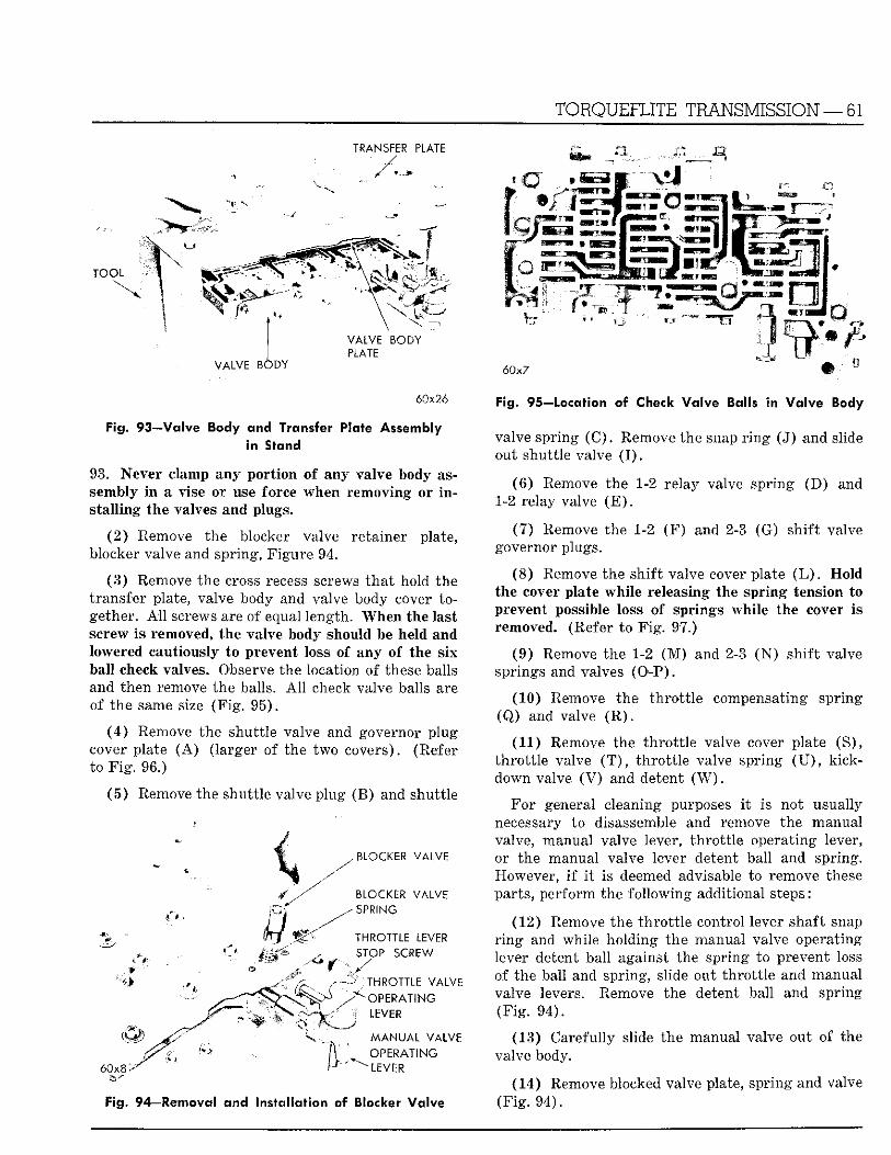
TORQUEFLITE TRANSMISSION —61
TRANSFER PLATE
T O O L
V A L V E B O D Y
V A L V E B O D Y PLATE
6 0 x 7
60x26
Fig. 93—Valve Body and Transfer Plate Assembly in Stand
93. Never clamp any por t ion of any valve body assembly i n a vise or use force when removing or i n s ta l l ing the valves and plugs,
(2 ) Remove the blocker valve retainer plate, blocker valve and spring, F igure 94.
(3 ) Remove the cross recess screws tha t hold the t ransfer plate, valve body and valve body cover together. A l l screws are of equal length. When the last screw is removed, the valve body should be held and lowered cautiously to prevent loss of any of the six ball check valves. Observe the location of these balls and then remove the balls. A l l check valve balls are of the same size ( F i g . 95) .
( 4 ) Remove the shutt le valve and governor plug cover plate ( A ) (larger of the two covers). (Refer to F i g . 96.)
(5 ) Remove the shutt le valve plug (B) and shuttle
BLOCKER VALVE
BLOCKER VALVE SPRING
THROTTLE LEVER STOP S C R E W
60x8
' T H R O T T L E VALVE " O P E R A T I N G
L E V E R
M A N U A L V A L V E
O P E R A T I N G
" L E V E R
Fig. 94—Removal and Installation of Blocker Va lve
Fig. 95—Location of Check Valve Balls in Va lve Body
valve spr ing ( C ) . Remove the snap r i n g (J) and slide out shutt le valve ( I ) .
(6 ) Remove the 1-2 relay valve spring ( D ) and 1-2 relay valve ( E ) .
(7 ) Remove the 1-2 ( F ) and 2-3 (G) shi f t valve governor plugs.
(8 ) Remove the sh i f t valve cover plate ( L ) . Hold the cover plate whi le releasing the spr ing tension to prevent possible loss of springs whi le the cover is removed. (Refer to F i g . 97.)
(9 ) Remove the 1-2 ( M ) and 2-3 ( N ) sh i f t valve springs and valves ( O P ) .
(10) Remove the t h ro t t l e compensating spr ing (Q) and valve ( R ) .
(11) Remove the th ro t t l e valve cover plate (S) , t h ro t t l e valve ( T ) , t h ro t t l e valve spring ( U ) , k ick-down valve ( V ) and detent ( W ) .
For general cleaning purposes i t is not usually necessary to disassemble and remove the manual valve, manual valve lever, t h ro t t l e operating lever, or the manual valve lever detent ball and spring. However, i f i t is deemed advisable to remove these parts, per form the fo l lowing additional steps:
(12) Remove the t h ro t t l e control lever shaft snap r i n g and while holding the manual valve operating lever detent ball against the spring to prevent loss of the ball and spring, slide out th ro t t l e and manual valve levers. Remove the detent ball and spring (F ig . 94) .
(13) Carefully slide the manual valve out of the valve body.
(14) Remove blocked valve plate, spr ing and valve ( F i g . 94) .
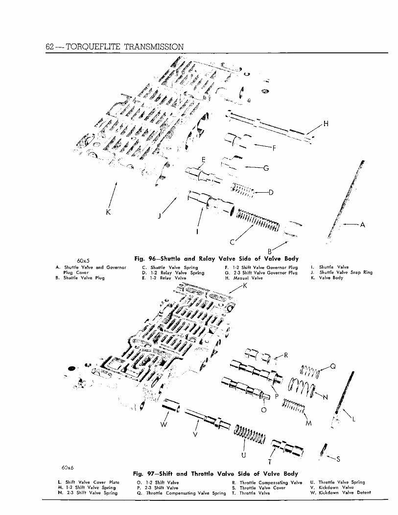
62 —TORQUEFLITE TRANSMISSION
mmmWl
••H
-D
- A
60x5 A. Shuttle Valve and Governor
Plug Cover B. Shuttle Valve Plug
Fig. 96—Shuttle and Relay Va lve Side of Valve Body C. Shuttle Valve Spring D. 1-2 Relay Valve Spring E. 1-2 Relay Valve
F. 1-2 Shift Valve Governor Plug G . 2-3 Shift Valve Governor Plug H. Manual Valve
I. Shuttle Valve J . Shuttle Valve Snap Ring K. Valve Body
V
i
u / 60x6
L. Shift Valve Cover Plate M. 1-2 Shift Valve Spring N. 2-3 Shift Valve Spring
Fig. 97—Shift and Throttle Va lve Side of Valve Body O. 1-2 Shift Valve R. Throttle Compensating Valve P. 2-3 Shift Valve S. Throttle Valve Cover Q. Throttle Compensating Valve Spring T. Throttle Valve
U. Throttle Valve Spring V. Kickdown Valve W. Kickdown Vatve Detent
T O R Q U E F L I T E T R A N S M I S S I O N — 63
110. V A L V E BODY, V A L V E BODY PLATE AND TRANSFER PLATE — C L E A N I N G AND INSPECTION
Place a l l parts i n clean solvent, wash thoroughly and dry w i t h compressed air . Make definitely sure all passages are free f rom obstructions. When inspecting, also check for porous castings. Inspect al l mat ing surfaces fo r burrs , nicks and grooves. The small ones may be removed w i t h very fine wet or d ry sand paper (400 g r i t ) ; otherwise, the damaged parts must be replaced w i t h new parts. Us ing straightedge, Tool C-3335, check al l ma t ing surfaces for d is tor t ion .
Us ing a pen l igh t , inspect the bores i n the valve body for score marks, pi ts , and i r regular i t ies . I n spect al l springs for d is tor t ion and collapsed coils. Inspect a l l valves and plugs fo r burrs , nicks and scores. The small scratches may be removed w i t h crocus cloth provid ing extreme care is used not to round off the s h a r p edge port ion of va lve . The sharp edge por t ion is v i t a l l y impor tan t to th is type valve as i t helps to prevent d i r t and foreign mat t e r f r o m ge t t ing between valves and body, thus reducing possibilities of s t icking. Check the valves and plugs for free operation i n bores; they must fa l l freely i n bores when clean and dry .
Inspect the valve body plate fo r nicks, scratches, or b u r r s ; and make sure meter ing holes are open. Inspect the transfer plate fo r porosity. Inspect the machined surfaces for nicks and burrs .
The th ro t t l e operating lever stop screw should be inspected fo r being loose or worn . Be sure the lock nut is t i g h t . T h i s screw should never be removed or i t s posit ion changed. I t i s pre-set and controls the base thrott le pressure set t ing . Should i t become loose i t w i l l requi re carefu l r e a d j u s t m e n t w i t h a special serv ice tool. R e f e r to P a r a g r a p h 10 ( e ) f o r ad jus t ment procedure.
Inspect the manual and th ro t t l e valve operating levers and shafts for being bent, worn, or the levers loose on the i r shafts. I f bent or worn they should be replaced. I f the levers are loose on shafts, they may be silver soldered only, otherwise they must be replaced w i t h new parts.
All valves should be installed dry and w i t h a ro ta t ing mot ion.
111. V A L V E BODY, V A L V E BODY PLATE A N D TRANSFER PLATE — ASSEMBLY
( 1 ) Whi le holding the valve body, w i t h the o i l passage ways facing downward, insert the manual valve operating lever detent spr ing in to the valve
body recess followed by the detent ball . Hold the bal l against the spr ing w i t h the fingers to prevent loss.
( 2 ) Slide the th ro t t l e lever shaft up th rough the valve body w i t h the smallest cam contacting the end of t h ro t t l e lever stop screw, as shown in Figure 94.
( 3 ) Whi le cont inuing to hold the detent bal l against spring, slide the manual operating lever down over the th ro t t l e valve shaft and at the same t ime index the a rm on the lever in to the end groove of the manual valve. The detent notches in the lever should slide down against the detent ball .
( 4 ) Ins t a l l the snap r i n g over the th ro t t l e lever shaft. Rotate the manual lever to see t ha t detent and valve operate freely.
(5) (Refer to F i g . 97,) Slide the k ickdown detent ( W ) (counterbored end f i rs t ) over the machined end of the k ickdown valve ( V ) , and then slide the assembly ( W - V ) , detent end first , into the valve body. Ins ta l l the t h ro t t l e valve spr ing ( U ) into the valve body followed by the t h ro t t l e valve ( T ) , spr ing pi lo t end first. Ins ta l l the t h r o t t l e valve cover plate (S) and t igh ten the screw 25 to 30 inch-pounds torque.
( 6 ) Ins ta l l the 1-2 and 2-3 sh i f t valves (O-P) w i t h the spr ing pi lo t ends pointed outward followed by springs ( M - N ) .
( 7 ) Ins ta l l the t h ro t t l e compensating valve (R) w i t h spr ing pi lot end outward followed by the th ro t t l e compensating pressure spr ing ( Q ) .
( 8 ) Ins ta l l the sh i f t valve cover plate ( L ) and t igh ten the screws 25 to 30 inch-pounds torque.
( 9 ) T u r n the valve body over and refer to Figure 96. Ins ta l l the shuttle valve ( I ) , small end first in to valve body and instal l the snap r i n g ( J ) . The snap r i n g should be replaced i f i t does not f i t securely.
( 1 0 ) Ins ta l l shut t le valve spring (C) followed by the shutt le valve plug ( B ) .
(11 ) Inser t the 1-2 relay valve ( E ) , spr ing pi lo t end outward, followed by relay valve spr ing (D) in to valve body.
( 1 2 ) Ins ta l l the 1-2 and 2-3 shi f t valve governor plugs ( F - G ) .
( 1 3 ) Place the shutt le valve and governor p lug plate cover ( A ) on valve body and t i gh ten screws 25 to 30 inch-pounds torque.
(14 ) Place the six ball checks i n the i r respective positions i n the valve body, as shown i n F igure 95.
( 1 5 ) Set the t ransfer plate cover ( t h i n steel plate) over the stand pilots, Tool C-3528, as shown i n F igu re
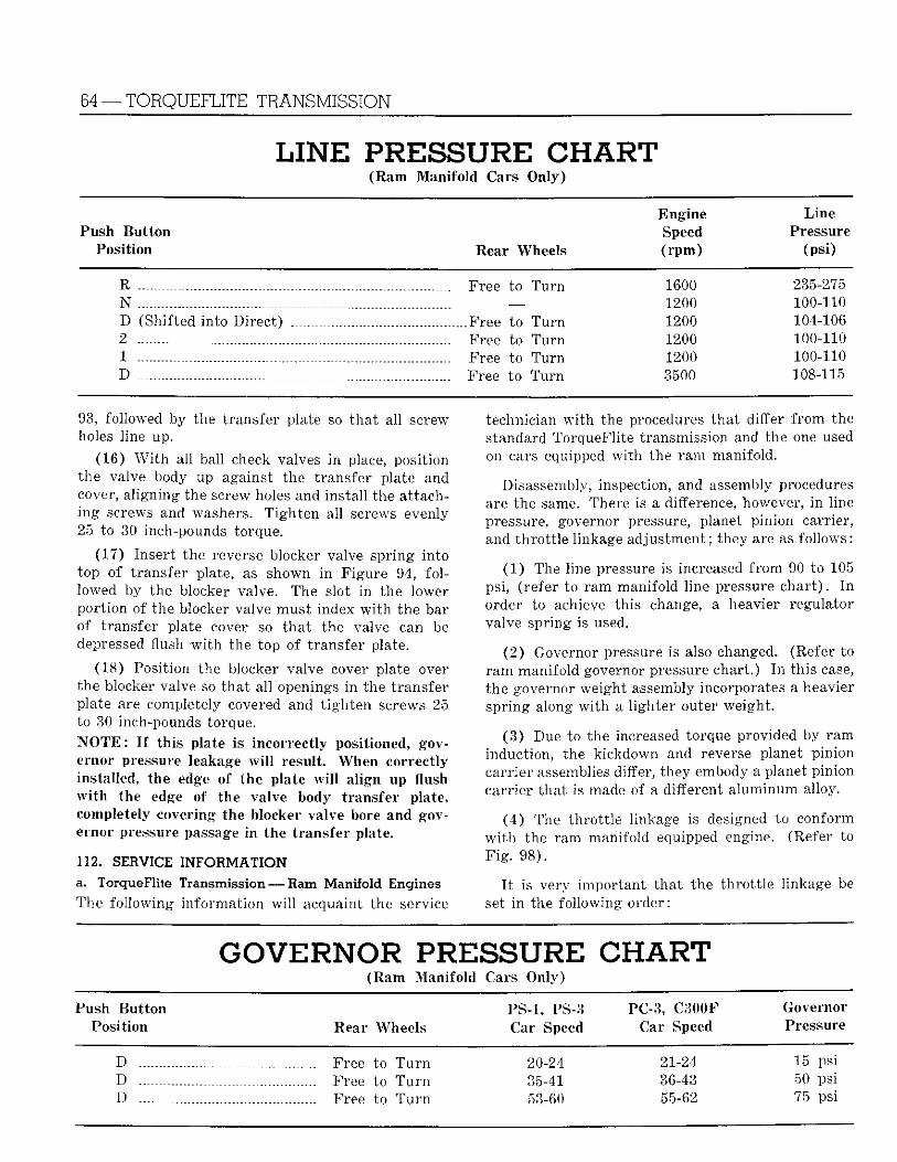
64 —TORQUEFLITE TRANSMISSION
LINE PRESSURE CHART (Ram Manifold Cars Only)
Engine Line Push Bu t ton Speed Pressure
Position Rear Wheels ( r p m ) (psi)
R Free to T u r n 1600 235-275 N — 1200 100-110 D (Shifted into Di rec t ) Free to T u r n 1200 104-106 2 Free to T u r n 1200 100-110 1 Free to Turn 1200 100-110 D Free to T u r n 3500 108-115
93, followed by the transfer plate so tha t all screw holes line up.
(16) W i t h al l ball check valves i n place, position the valve body up against the transfer plate and cover, a l igning the screw holes and instal l the at tachi n g screws and washers. T igh ten all screws evenly 25 to 30 inch-pounds torque.
(17) Insert the reverse blocker valve spr ing into top of transfer plate, as shown i n Figure 94, fo l lowed by the blocker valve. The slot i n the lower por t ion of the blocker valve must index w i t h the bar of t ransfer plate cover so tha t the valve can be depressed flush w i t h the top of t ransfer plate.
(18) Posit ion the blocker valve cover plate over the blocker valve so tha t al l openings in the t ransfer plate are completely covered and t i gh ten screws 25 to 30 inch-pounds torque. N O T E : I f th is plate is incorrect ly positioned, governor pressure leakage w i l l result . When correct ly installed, the edge of the plate w i l l al ign up flush w i t h the edge of the valve body transfer plate, completely covering the blocker valve bore and governor pressure passage i n the t ransfer plate.
112. SERVICE INFORMATION a. TorqueFlite Transmission — Ram Manifold Engines The fol lowing in format ion w i l l acquaint the service
technician w i t h the procedures tha t differ f r o m the standard TorqueFlite transmission and the one used on cars equipped w i t h the r am manifold.
Disassembly, inspection, and assembly procedures are the same. There is a difference, however, i n line pressure, governor pressure, planet pinion carrier, and th ro t t l e linkage adjustment; they are as fol lows:
(1 ) The line pressure is increased f rom 90 to 105 psi, (refer to r am manifold line pressure cha r t ) . I n order to achieve this change, a heavier regulator valve spring is used.
(2 ) Governor pressure is also changed. (Refer to r a m manifold governor pressure chart .) I n this case, the governor weight assembly incorporates a heavier spr ing along w i t h a l ighter outer weight .
(3 ) Due to the increased torque provided by r a m induction, the kickdown and reverse planet pinion carr ier assemblies differ, they embody a planet pinion carrier that is made of a different a luminum alloy.
(4 ) The th ro t t l e linkage is designed to conform w i t h the ram manifold equipped engine. (Refer to F i g . 98) .
I t is very impor tant tha t the th ro t t l e linkage be set i n the fol lowing order:
GOVERNOR P R E S S U R E CHART (Ram Manifold Cars Only)
Push Bu t ton PS-1, PS-3 PC-3, C300F Governor Position Rear Wheels Car Speed Car Speed Pressure
D Free to T u r n 20-24 21-24 15 psi D Free to T u r n 35-41 36-43 50 psi D Free to T u r n 53-60 55-62 75 psi
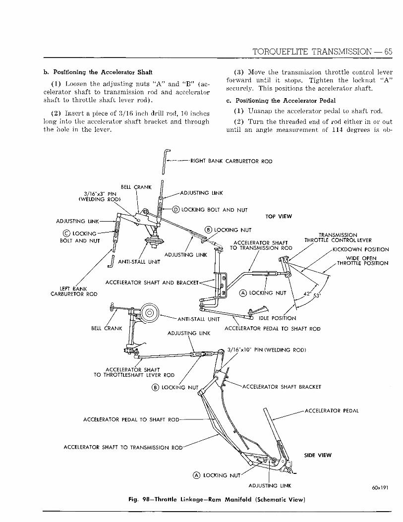
TORQUEFLITE TRANSMISSION — 65
b. Positioning the Accelerator Shaft
(1 ) Loosen the adjust ing nuts " A " and " B " (accelerator shaft to transmission rod and accelerator shaft to th ro t t l e shaft lever r od ) .
(2 ) Inser t a piece of 3/16 inch d r i l l rod, 10 inches long into the accelerator shaft bracket and through the hole i n the lever.
(3) Move the transmission th ro t t l e control lever fo rward u n t i l i t stops. Tighten the locknut " A " securely. This positions the accelerator shaft.
Co Positioning the Accelerator Pedal
(1 ) Unsnap the accelerator pedal to shaft rod.
(2 ) T u r n the threaded end of rod either i n or out un t i l an angle measurement of 114 degrees is ob-
-RIGHT BANK CARBURETOR ROD
BELL CRANK 3/16"x3" PIN
(WELDING ROD)
ADJUSTING LINK
© LOCKING BOLT AND NUT
ADJUSTING LINK
(6) LOCKING BOLT AND NUT
(D LOCKING NUT
ACCELERATOR SHAFT TO TRANSMISSION ROD
LEFT BANK CARBURETOR ROD
TOP VIEW
TRANSMISSION THROTTLE CONTROL LEVER
KICKDOWN POSITION
WIDE OPEN THROTTLE POSITION
0 LOCKING NUT
BELL CRANK
ANTI-STALL UNIT IDLE POSITION
ACCELERATOR PEDAL TO SHAFT ROD
3/16"xl0" PIN (WELDING ROD)
ACCELERATOR SHAFT TO THROTTLESHAFT LEVER ROD
ACCELERATOR SHAFT BRACKET
ACCELERATOR PEDAL
ACCELERATOR PEDAL TO SHAFT ROD
ACCELERATOR SHAFT TO TRANSMISSION ROD SIDE VIEW
@ LOCKING NUT"
ADJUSTING LINK
Fig. 98—Thrott le Linkage—Ram M a n i f o l d (Schematic V i ew)
60x191
66 — TORQUEFLITE TRANSMISSION
tained between the floor of car and the flat face of the accelerator pedal.
(3 ) This angle can be obtained w i t h a protractor .
(4) A f t e r correct measurement has been obtained, connect the rod. Remove the locating p in f r o m accelerator shaft bracket.
d. Setting the Bellcrank (1 ) Inspect each carburetor to be sure the choke
valves are open; tha t the fast idle cams are released and the th ro t t l e valves are closed.
( 2 ) Loosen the locking nuts "C" and " D " ( lef t
and r i g h t bank carburetor rods) .
(3) Back off the anti-stall adjust ing plunger far enough to allow the bellcrank to be pivoted.
(4) Pivot the bellcrank u n t i l a 3/16 inch piece of d r i l l rod 3 inches long can be inserted th rough the bellcrank hole and down into the intake manifold.
(5 ) T ighten locking nuts " C " and " D " securely. Remove the % 6 inch d r i l l rod f r o m the bellcrank.
(6) Push rearward on the accelerator shaft to th ro t t l e shaft lever rod adjust ing l ink , u n t i l the stop is reached. T igh ten locking nut securely.
TORQUE CONVERTER S E R V I C E PROCEDURES
113. REMOVAL AND INSTALLATION OF TORQUE CONVERTER AND HOUSING
a. Removal
(1) Remove the transmission as outl ined in Paragraph 26 .
( 2 ) Remove the converter housing dust shield and s t a r t ing motor. Remove the torque converter housing-to-engine block, (or adapter plate) bolts and washers. As the housing is doweled to the engine block (or adapter plate) , care must be exercised dur ing removal. Do not hammer or p r y between the mat ing surfaces to loosen, as the metal may be distor ted which can result in misalignment.
(3 ) A f t e r removing the housing, inspect the mating surfaces of the housing and engine block (or adapter p la te) . Remove al l burrs or rough spots w i t h emery cloth. Remove all obstructions, d i r t , etc. f r o m vent hole screens (when so equipped).
(4) Us ing wrench, Tool C-589, remove the stud nuts and lock washers which hold the converter uni t to the crankshaft . The torque converter assembly is a welded un i t and cannot be serviced, except as an assembly.
b. Installation
(1 ) [ f a new torque converter is being installed, make sure al l visible foreign mat ter , such as raised metal around studs, burrs, chips, etc. have been re
moved f rom the converter and crankshaft dr ive flanges.
( 2 ) Measure the crankshaft flange runout (maxi m u m is .002 inch to ta l indicator reading) by using dial indicator set, Tool C-3339, at one of the engine block to housing bolt holes. Checking the crankshaft flange runout w i l l determine whether or not the crankshaft flange may be cont r ibu t ing to torque converter hub runout.
I f the crankshaft flange runout is w i t h i n tolerance, proceed to instal l the torque converter and housing as fol lows:
(3 ) Position the torque converter un i t on the crankshaft flange. Using wrench, Tool C-589, t igh ten the stud nuts to specifications.
Before ins ta l l ing the torque converter housing, i t is recommended tha t the torque converter hub r u n out be checked (and corrected i f necessary) as outlined in Paragraph 115. I f the torque converter hub runout is w i t h i n specifications, continue to instal l the housing i n the fol lowing manner:
( 4 ) Position the housing over the dowels and against ma t ing face of the engine block (or adapter pla te) . T ighten the mount ing bolts j u s t snug enough to re ta in the housing i n position.
( 5 ) Check (and correct i f necessary) the torque converter housing bore and face runout as outlined i n Paragraph 4. I f the bore and face runout are
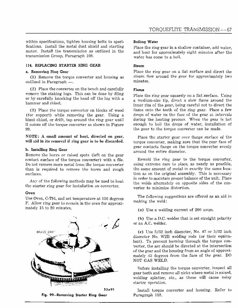
TORQUEFLITE TRANSMISSION — 67
w i t h i n specifications, t igh ten housing bolts to specifications. Ins ta l l the metal dust shield and s ta r t ing motor. Ins ta l l the transmission as outlined i n the transmission Group, Paragraph 108.
114. REPLACING STARTER RING GEAR
a. Removing Ring Gear (1) Remove the torque converter and housing as
outlined i n Paragraph — .
(2) Place the converter on the bench and carefully remove the s taking lugs. This can be done by f i l ing or by carefully knocking the head off the lug w i t h a hammer and chisel.
(3 ) Place the torque converter on blocks of wood (for support) whi le removing the gear. Us ing a b lunt chisel, or d r i f t , tap around the r i n g gear u n t i l i t comes off the torque converter as shown i n F igure 99.
N O T E : A small amount of heat, directed on gear, w i l l aid i n i t s removal i f r i n g gear is to be discarded.
b. Installing Ring Gear Remove the burrs or raised spots ( lef t on the gear contact surface of the torque converter) w i t h a file. Do not remove more metal f rom the torque converter than is required to remove the burrs and rough surfaces.
A n y of the fol lowing methods may be used to heat the s tar ter r i n g gear for instal lat ion on converter.
Oven Use Oven, C-794, and set temperature at 150 degrees F. A l l o w r i n g gear to remain i n the oven for approximately 15 to 20 minutes.
5 3 x 9 1
Fig. 99—Removing Starter Ring Gear
Boiling Water
Place the r i n g gear i n a shallow container, add water, and heat for approximately eight minutes after the water has come to a boil .
Steam
Place the r i n g gear on a flat surface and direct the steam flow around the gear for approximately two minutes.
Flame
Place the r i n g gear squarely on a flat surface. Us ing a medium-size t ip , direct a slow flame around the inner r i m of the gear, being careful not to direct the flame onto the teeth of the r i n g gear. Place a few drops of water on the face of the gear at intervals du r ing the heating process. When the gear is hot enough to boil the drops of water, ins ta l la t ion of the gear to the torque converter can be made.
Place the starter gear over flange surface of the torque converter, mak ing sure tha t the rear face of gear contacts flange on the torque converter evenly around the entire diameter.
Reweld the r i n g gear to the torque converter, using extreme care to place, as nearly as possible, the same amount of metal i n exactly the same locat ion as on the or ig inal assembly. This is necessary in order to mainta in proper balance of the un i t . Place the welds alternately on opposite sides of the conver ter to minimize dis tor t ion.
The fo l lowing suggestions are offered as an aid i n mak ing the weld :
(a ) Use a welding current of 200 amps.
( b ) Use a D.C. welder tha t is set s t ra ight po la r i ty or an A .C . welder.
(c) Use 5/32 inch diameter, No . 47 or 5/32 inch diameter No. W 2 B welding rods (or the i r equivalent) . To prevent bu rn ing th rough the torque converter, the arc should be directed at the intersection of the gear and the housing f r o m an angle of approximately 45 degrees f r o m the face o f the gear. DO N O T GAS W E L D .
Before ins ta l l ing the torque converter, inspect al l gear teeth and remove al l nicks where metal is raised, welding splatter, etc., as these w i l l cause noisy star ter operation.
Ins ta l l torque converter and housing. Refer to Paragraph 113.
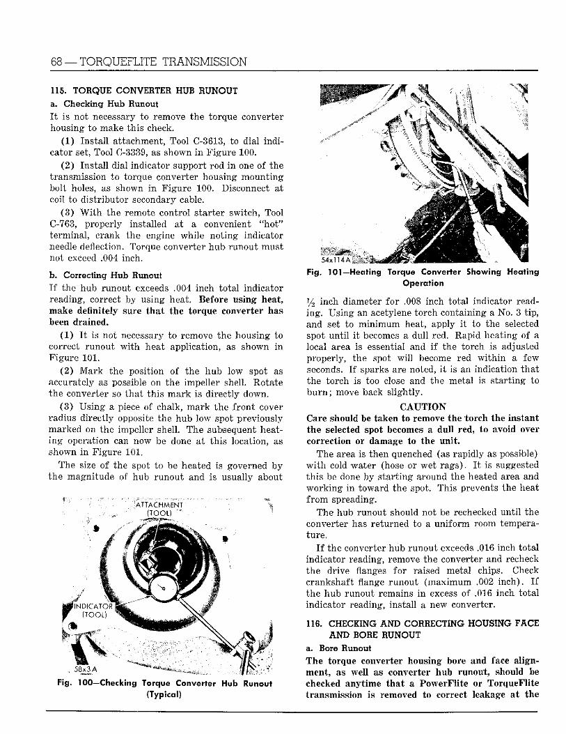
68 —TORQUEFLITE TRANSMISSION
115. TORQUE CONVERTER HUB RUNOUT a. Checking Hub Runout I t is not necessary to remove the torque converter housing to make this check.
(1 ) Ins ta l l attachment, Tool C-3613, to dial i nd i cator set, Tool C-3339, as shown i n Figure 100.
(2 ) Ins ta l l dial indicator support rod i n one o f the transmission to torque converter housing mount ing bolt holes, as shown i n F igure 100. Disconnect at coil to d i s t r ibu tor secondary cable.
(3 ) W i t h the remote control s tarter switch, Tool C-763, properly installed at a convenient "ho t" terminal , crank the engine whi le no t ing indicator needle deflection. Torque converter hub runout must not exceed .004 inch.
b. Correcting Hub Runout I f the hub runout exceeds .004 inch to ta l indicator reading, correct by using heat. Before using heat, make definitely sure that the torque converter has been drained.
(1 ) I t is not necessary to remove the housing to correct runout w i t h heat application, as shown i n Figure 101.
(2) M a r k the position of the hub low spot as accurately as possible on the impeller shell. Rotate the converter so tha t th i s m a r k is direct ly down.
(3 ) Us ing a piece of chalk, mark the f ron t cover radius direct ly opposite the hub low spot previously marked on the impeller shell. The subsequent heati n g operation can now be done at th i s location, as shown i n Figure 101.
The size of the spot to be heated is governed by the magnitude of hub runout and is usually about
(TOOL) ^ ^ ^ ^ ^ ^ • ^ ^ ^ K i
§111111™ f* i^m^^^^:':i::. ' :<:< » -Si*;|iBiiB Bi ^ R I K K i l l (TOOL) l l l i lw
Fig. H00—Checking Torque Converter Hub Runouft (Typical)
i
Fig. 101J—Heating Torque Converter Showing Heating Operation
y2 inch diameter fo r .008 inch tota l indicator reading . Using an acetylene torch containing a No. 3 t ip , and set to m i n i m u m heat, apply i t to the selected spot u n t i l i t becomes a dul l red. Rapid heating of a local area is essential and i f the torch is adjusted properly, the spot w i l l become red w i t h i n a few seconds. I f sparks are noted, i t is an indication tha t the torch is too close and the metal is s ta r t ing to b u r n ; move back s l ight ly .
C A U T I O N Care should be taken to remove the torch the instant the selected spot becomes a dul l red, to avoid over correction or damage to the un i t .
The area is then quenched (as rapidly as possible) w i t h cold water (hose or wet rags) . I t is suggested th i s be done by s ta r t ing around the heated area and w o r k i n g i n toward the spot. This prevents the heat f r o m spreading.
The hub runout should not be rechecked u n t i l the converter has returned to a un i fo rm room temperature .
I f the converter hub runout exceeds .016 inch to ta l indicator reading, remove the converter and recheck the drive flanges fo r raised metal chips. Check crankshaft flange runout (max imum .002 inch) . I f the hub runout remains i n excess of .016 inch to ta l indicator reading, instal l a new converter.
116. CHECKING AND CORRECTING HOUSING FACE AND BORE RUNOUT
a. Bore Runout The torque converter housing bore and face al ignment, as wel l as converter hub runout , should be checked anyt ime tha t a PowerFl i te or TorqueFli te transmission is removed to correct leakage at the
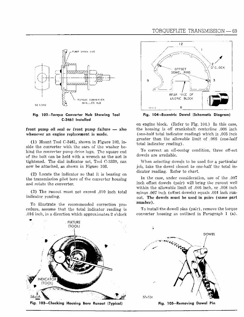
TORQUEFLITE TRANSMISSION — 69
PUMP DRIVE LUG
T O R Q U E C O N V E R T E R MPELLER HUB
Fig. 102—Torque Converter Hub Showing Tool C-3461 Installed
f ron t pump oi l seal or f ron t pump fai lure — also whenever an engine replacement is made.
(1 ) Mount Tool C-3461, shown i n F igure 102, i n side the converter w i t h the ears of the washer beh i n d the converter pump drive lugs. The square end of the bolt can be held w i t h a wrench as the nu t is t ightened. The dial indicator set, Tool C-3339, can now be attached, as shown i n Figure 103.
(2 ) Locate the indicator so tha t i t is bearing on the transmission pi lo t bore of the converter housing and rotate the converter.
(3 ) The runout must not exceed .010 inch to ta l indicator reading.
To i l lust ra te the recommended correction procedure, assume t h a t the to ta l indicator reading is .016 inch, i n a direct ion which approximates 2 o'clock
^ f l « ^ ^ ^ ^ ^ ^ ^ B (TOOL)
INDICATOR
58x1 A
Fig. 104—Eccentric Dowel (Schematic Diagram)
on engine block. (Refer to F i g . 104.) I n this case, the housing is off crankshaft centerline .008 inch (one-half to ta l indicator reading) which is .003 inch greater than the allowable l i m i t of .005 (one-half to ta l indicator reading) .
To correct an off-center condition, three off-set dowels are available.
When selecting dowels to be used for a par t icular job, take the dowel closest to one-half the to ta l i n dicator reading. Refer to chart .
I n the case, under consideration, use of the .007 inch offset dowels (pai r ) w i l l b r i ng the runout well w i t h i n the allowable l i m i t of .005 inch, or .008 inch minus .007 inch (offset dowels) equals .001 inch runout. The dowels must be used i n pairs (same par t number ) .
To instal l the dowell pins (pa i r ) , remove the torque converter housing as outlined i n Paragraph 1 ( a ) .
D O W E L
57x524
Fig. 103—Checking Housing lo re Runout (Typical) Fig. 105—Removing Dowel Pin
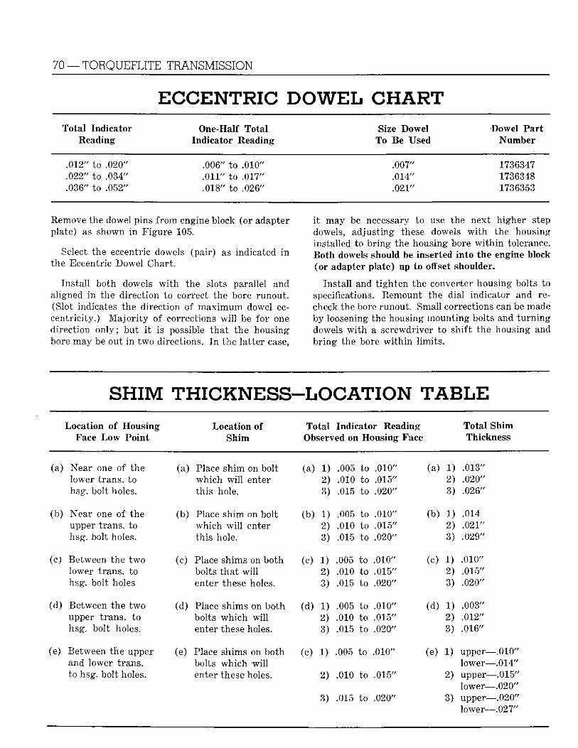
70 —TORQUEFLITE TRANSMISSION
E C C E N T R I C DOWEL CHART Total Indicator
Reading One-Half Total
Indicator Reading Size Dowel
To Be Used Dowel Pa r t
Number
.012" to .020" .006" to .010" .007" 1736347
.022" to .034" .011" to .017" .014" 1736348
.036" to .052" .018" to .026" .021" 1736353
Remove the dowel pins f rom engine block (or adapter plate) as shown i n Figure 105.
Select the eccentric dowels (pair) as indicated i n the Eccentric Dowel Chart .
Ins ta l l both dowels w i t h the slots parallel and aligned i n the direct ion to correct the bore runout . (Slot indicates the direction of m a x i m u m dowel eccentr ic i ty . ) M a j o r i t y of corrections w i l l be for one direct ion on ly ; but i t is possible tha t the housing bore may be out i n two directions. I n the la t ter case,
i t may be necessary to use the next higher step dowels, adjust ing these dowels w i t h the housing installed to b r ing the housing bore w i t h i n tolerance. Bo th dowels should be inserted in to the engine block (or adapter plate) up to offset shoulder.
Ins ta l l and t igh ten the converter housing bolts to specifications. Remount the dial indicator and recheck the bore runout. Small corrections can be made by loosening the housing mount ing bolts and t u r n i n g dowels w i t h a screwdriver to sh i f t the housing and b r ing the bore w i t h i n l imi t s .
SHIM THICKNESS-LOCATION T A B L E Location of Housing Location of Tota l Indicator Reading Tota l Shim
Face L o w Point Shim Observed on Housing Face Thickness
(a) Near one of the (a) Place shim on bolt (a) 1) .005 to .010" (a) 1) .013" lower trans, to which w i l l enter 2) .010 to .015" 2) .020" hsg. bolt holes. th is hole. 3) .015 to .020" 3) .026"
(b) Near one of the (b) Place shim on bolt (b) 1) .005 to .010" (b) 1) .014 upper trans, to which w i l l enter 2) .010 to .015" 2) .021" hsg. bolt holes. th is hole. 3) .015 to .020" 3) .029"
(c) Between the two (c) Place shims on both (c) 1) .005 to .010" (c) 1) .010" lower trans, to bolts t ha t w i l l 2) .010 to .015" 2) .015" hsg. bolt holes enter these holes. 3) .015 to .020" 3) .020"
(d) Between the t w o (d) Place shims on both (d) 1) .005 to .010" (d) 1) .003" upper trans, to bolts wh ich w i l l 2) .010 to .015" 2) .012" hsg. bolt holes. enter these holes. 3) .015 to .020" 3) .016"
(e) Between the upper (e) Place shims on both (e) 1) .005 to .010" (e) 1) u p p e r - -.010" and lower trans. bolts which w i l l lower— -.014" to hsg. bolt holes. enter these holes. 2) .010 to .015" 2) uppe r - -.015"
lower— -.020" 3) .015 to .020" 3) upper— -.020"
lower—.027 ;
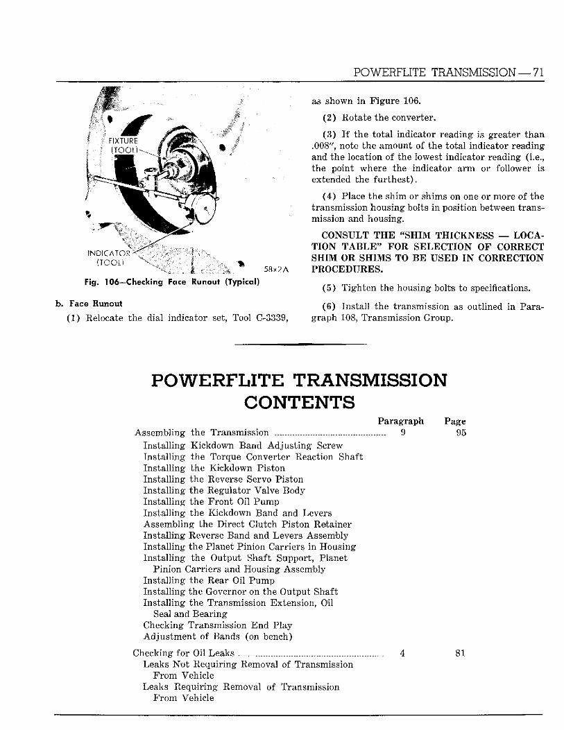
POWERFLITE TRANSMISSION — 71
I N D f C A I o i ^
(TOOL) K ' ^ B ^ ^
I 58x2 A Fig. 106—Checking Face Runout (Typical)
b . Face Runout
(1 ) Relocate the dial indicator set, Tool C-3339,
as shown i n F igure 106.
( 2 ) Rotate the converter.
(3 ) I f the to ta l indicator reading is greater than .008", note the amount of the to ta l indicator reading and the location of the lowest indicator reading (i.e., the point where the indicator a r m or follower is extended the fu r the s t ) .
(4 ) Place the shim or shims on one or more of the transmission housing bolts i n position between transmission and housing.
CONSULT T H E " S H I M T H I C K N E S S — LOCAT I O N T A B L E 9 * FOR S E L E C T I O N O F CORRECT S H I M OR S H I M S TO B E U S E D I N CORRECTION PROCEDURES.
(5 ) T igh ten the housing bolts to specifications.
(6 ) Ins ta l l the transmission as outlined i n Paragraph 108, Transmission Group.
P O W E R F L I T E TRANSMISSION CONTENTS
Paragraph Page Assembling the Transmission 9 95
Ins ta l l ing Kickdown Band A d j u s t i n g Screw Ins ta l l ing the Torque Converter Reaction Shaft Ins ta l l ing the Kickdown Piston Ins ta l l ing the Reverse Servo Piston Ins ta l l ing the Regulator Valve Body Ins ta l l ing the F ron t Oi l Pump Ins ta l l ing the Kickdown Band and Levers Assembling the Direct Clutch Piston Retainer Ins ta l l ing Reverse Band and Levers Assembly Ins ta l l ing the Planet Pinion Carriers i n Housing Ins ta l l ing the Output Shaft Support, Planet
Pinion Carriers and Housing Assembly Ins ta l l ing the Rear Oi l Pump Ins ta l l ing the Governor on the Output Shaft Ins ta l l ing the Transmission Extension, Oil
Seal and Bearing Checking Transmission End Play Adjus tmen t of Bands (on bench)
Checking for Oil Leaks _ 4 81 Leaks N o t Requir ing Removal of Transmission
F r o m Vehicle Leaks Requir ing Removal of Transmission
F r o m Vehicle
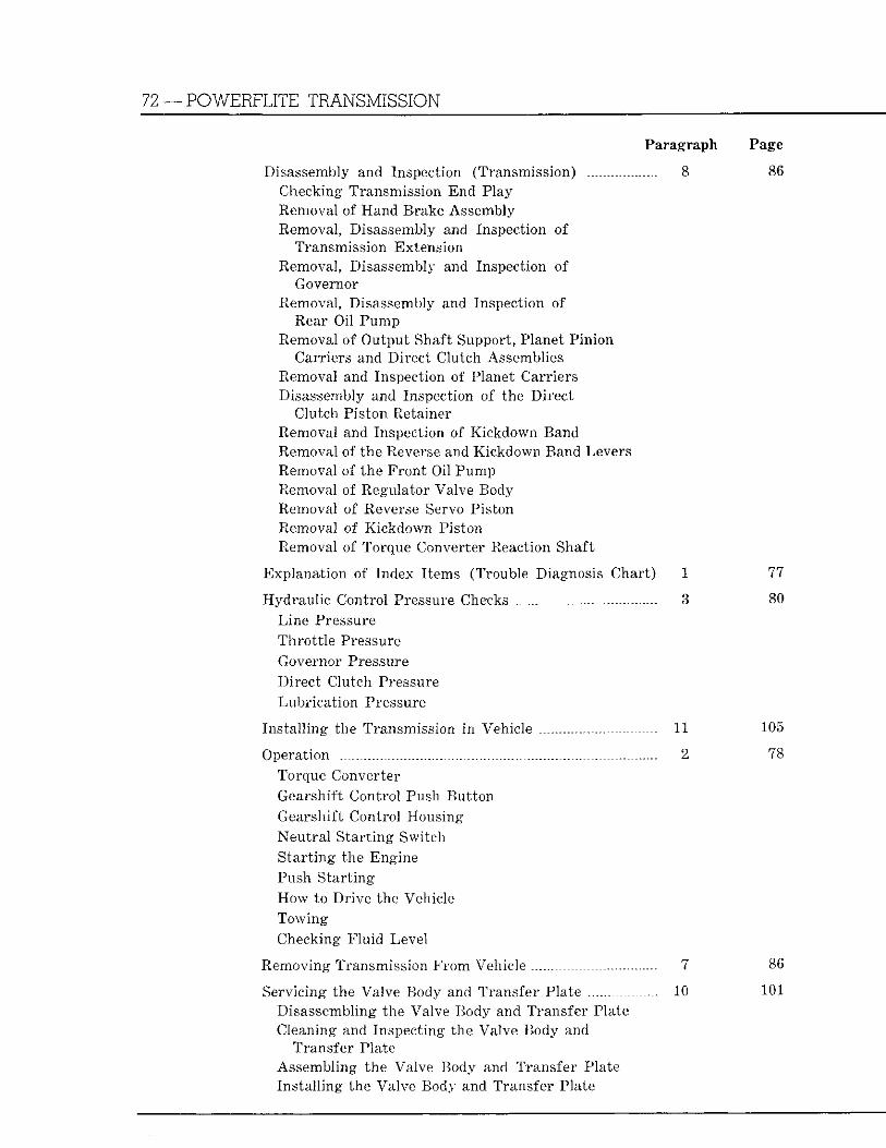
72 —POWERFLITE TRANSMISSION
Paragraph Page
Disassembly and Inspection (Transmission) 8 86 Checking Transmission End Play Removal of Hand Brake Assembly Removal, Disassembly and Inspection of
Transmission Extension Removal, Disassembly and Inspection of
Governor Removal, Disassembly and Inspection of
Rear Oil Pump Removal of Output Shaft Support, Planet Pinion
Carriers and Direct Clutch Assemblies Removal and Inspection of Planet Carriers Disassembly and Inspection of the Direct
Clutch Piston Retainer Removal and Inspection of Kickdown Band Removal of the Reverse and Kickdown Band Levers Removal of the F ron t Oil Pump Removal of Regulator Valve Body Removal of Reverse Servo Piston Removal of Kickdown Piston Removal of Torque Converter Reaction Shaft
Explanat ion of Index Items (Trouble Diagnosis Chart ) 1 77
Hydraul ic Control Pressure Checks 3 80 Line Pressure Thro t t l e Pressure Governor Pressure Direc t Clutch Pressure Lubr ica t ion Pressure
Ins ta l l ing the Transmission in Vehicle . 11 105
Operation _ 2 78 Torque Converter Gearshift Control Push Bu t ton Gearshift Control Housing Neu t r a l S ta r t ing Switch S ta r t ing the Engine Push S ta r t ing How to Dr ive the Vehicle Towing Checking F lu id Level
Removing Transmission F r o m Vehicle . 7 86
Servicing the Valve Body and Transfer Plate 10 101 Disassembling the Valve Body and Transfer Plate Cleaning and Inspecting the Valve Body and
Transfer Plate Assembling the Valve Body and Transfer Plate Ins ta l l ing the Valve Body and Transfer Plate
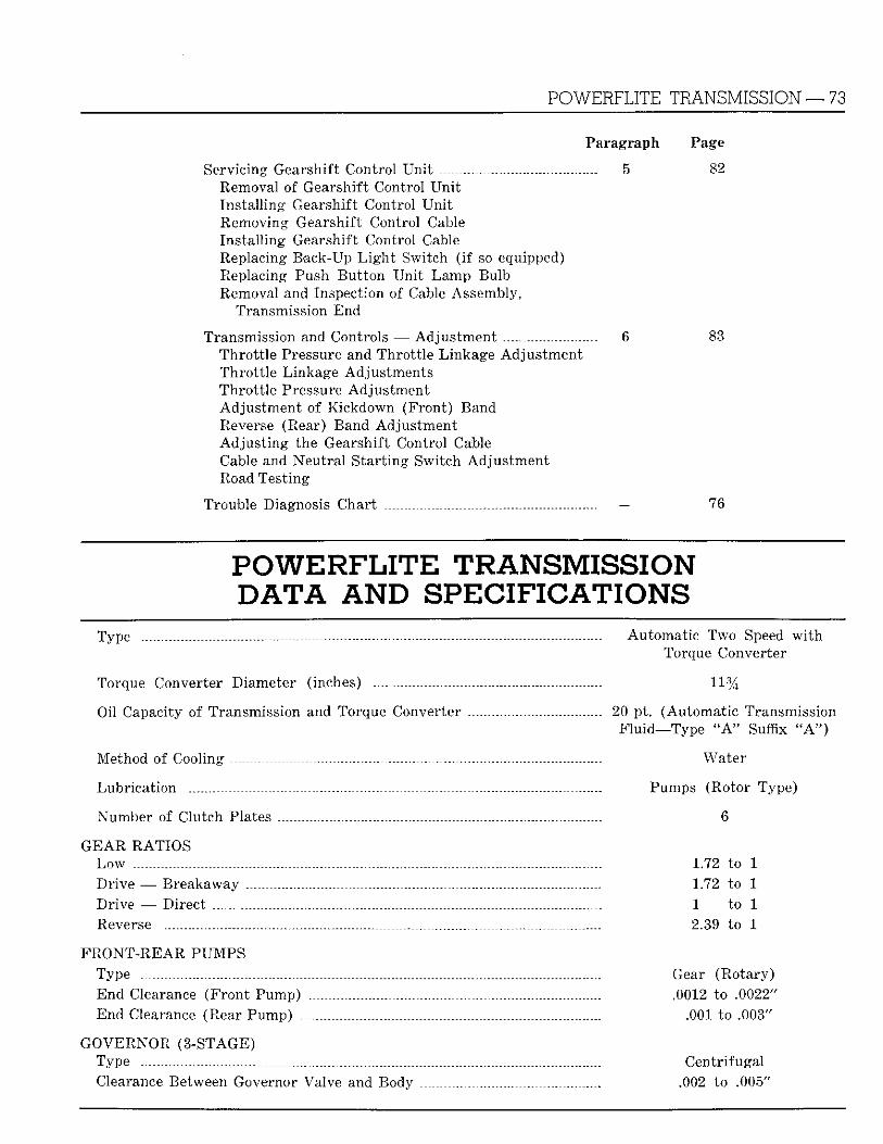
POWERFLITE TRANSMISSION — 73
Paragraph Page
Servicing Gearshift Control U n i t 5 82 Removal of Gearshift Control U n i t Ins ta l l ing Gearshift Control U n i t Removing Gearshift Control Cable Ins ta l l ing Gearshift Control Cable Replacing Back-Up L i g h t Switch ( i f so equipped) Replacing Push Bu t ton U n i t L a m p Bulb Removal and Inspection of Cable Assembly,
Transmission End
Transmission and Controls — Adjus tment 6 83 Thro t t l e Pressure and Thro t t l e Linkage Adjus tment Thro t t l e Linkage Adjustments Thro t t l e Pressure Adjus tment Adjus tment of Kickdown (F ron t ) Band Reverse (Rear) Band Adjus tment A d j u s t i n g the Gearshift Control Cable Cable and Neu t ra l S ta r t ing Switch Adjus tment Road Test ing
Trouble Diagnosis Char t — 76
P O W E R F L I T E TRANSMISSION DATA AND SPECIFICATIONS
Type Automat ic Two Speed w i t h
Torque Converter
Torque Converter Diameter (inches) 1 1 %
Oil Capacity of Transmission and Torque Converter 20 pt . (Automat ic Transmission
Fluid—Type " A " Suffix " A " )
Method of Cooling Wate r
Lubr ica t ion Pumps (Rotor Type)
Number of Clutch Plates 6
G E A R R A T I O S
Low 1.72 to 1 Dr ive — Breakaway . 1.72 to 1 Dr ive — Direc t 1 to 1 Reverse 2.39 to 1
F R O N T - R E A R PUMPS Type Gear (Rota ry) End Clearance (F ron t Pump) . .0012 to .0022" End Clearance (Rear Pump) .001 to .003"
GOVERNOR (3-STAGE) Type Centr ifugal Clearance Between Governor Valve and Body .002 to .005"
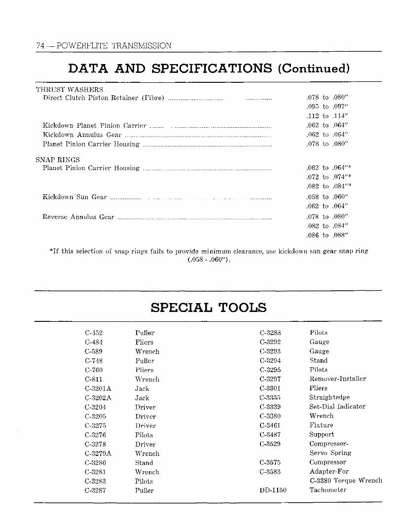
74 —POWERFLITE TRANSMISSION
DATA AND SPECIFICATIONS (Continued) T H R U S T W A S H E R S
Direct Clutch Piston Retainer (Fibre) .078 to .080" .095 to .097" .112 to .114"
Kickdown Planet Pinion Carrier _ .062 to .064" Kickdown Annulus Gear .062 to .064" Planet Pinion Carr ier Housing .078 to .080"
S N A P RINGS Planet Pinion Carrier Housing .062 to .064"*
.072 to .074"*
.082 to .084"*
Kickdown Sun Gear .058 to .060" .062 to .064"
Reverse Annulus Gear .078 to .080" .082 to .084" .086 to .088"
I f th is selection of snap r ings fails to provide m i n i m u m clearance, use kickdown sun gear snap r i n g ( .058- .060").
S P E C I A L TOOLS C-452 Puller C-3288 Pilots C-484 Pliers C-3292 Gauge
C-589 Wrench C-3293 Gauge C-748 Puller C-3294 Stand C-760 Pliers C-3295 Pilots
C-811 Wrench C-3297 Remover-Installer
C-3201A Jack C-3301 Pliers C-3202A Jack C-3335 Straightedge
C-3204 Dr ive r C-3339 Set-Dial Indicator
C-3205 D r i v e r C-3380 Wrench
C-3275 D r i v e r C-3461 F i x t u r e
C-3276 Pilots C-3487 Support
C-3278 Dr ive r C-3529 Compressor-
C-3279A W rench Servo Spring
C-3280 Stand C-3575 Compressor
C-3281 Wrench C-3583 Adapter-For
C-3283 Pilots C-3380 Torque Wrench
C-3287 Puller DD-1150 Tachometer
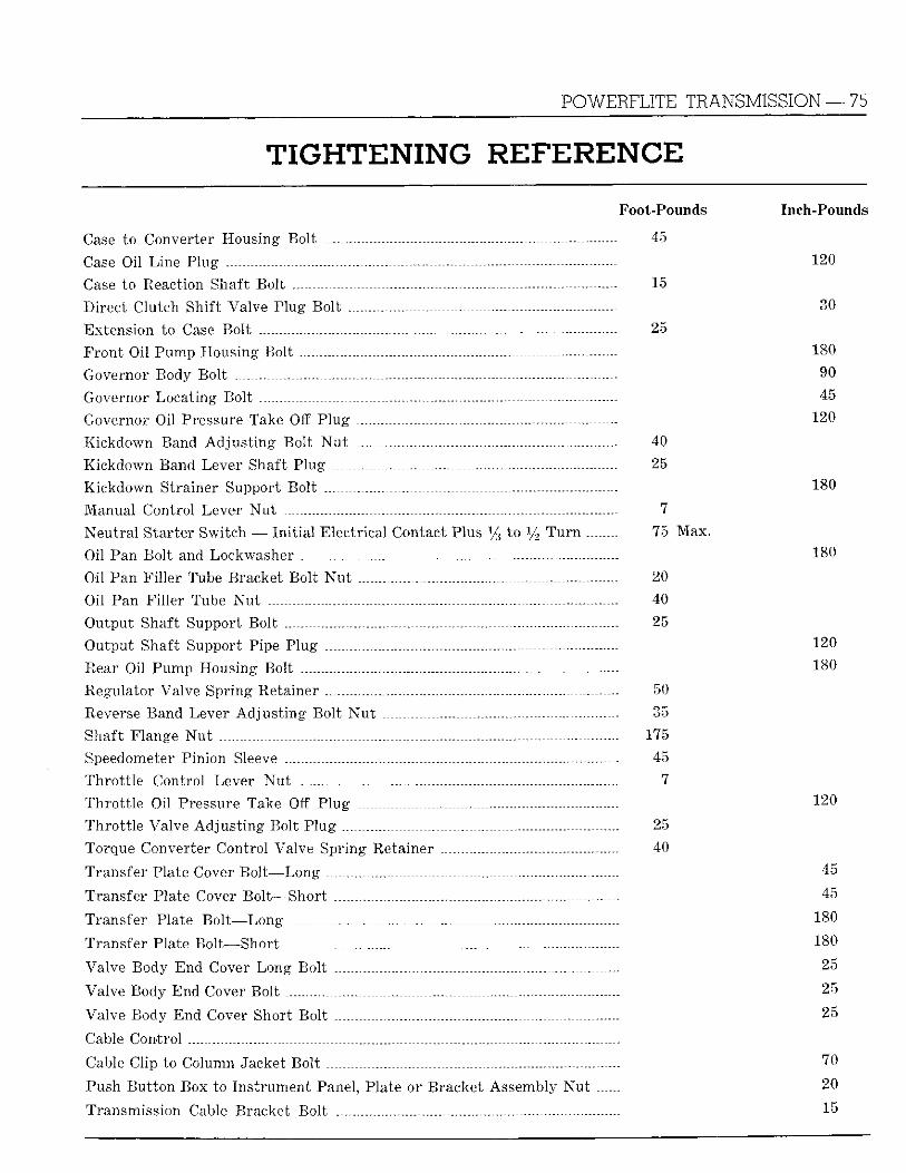
POWERFLITE TRANSMISSION — 75
TIGHTENING R E F E R E N C E Foot-Pounds
Case to Converter Housing Bol t 4 5
Case Oil Line Plug - -
Case to Reaction Shaft Bol t - 15
Direct Clutch Shif t Valve Plug Bol t
Extension to Case Bol t 2 5
Front Oil Pump Housing Bolt — .— . —
Governor Body Bol t
Governor Locat ing Bol t .
Governor Oil Pressure Take Off P lug
Kickdown Band A d j u s t i n g Bol t N u t . 4 0
Kickdown Band Lever Shaft Plug . 2 5
Kickdown Strainer Support Bol t
Manual Control Lever N u t 7
Neu t ra l Starter Switch — I n i t i a l Electr ical Contact Plus l / s to y 2 T u r n 7 5 Max.
Oil Pan Bol t and Lockwasher . ..
Oil Pan F i l l e r Tube Bracket Bol t N u t _ 2 0
Oil Pan F i l l e r Tube N u t 4 0
Output Shaft Support Bol t 2 5
Output Shaft Support Pipe Plug . -
Rear Oil Pump Housing Bolt .
Regulator Valve Spring Retainer 5 0
Reverse Band Lever Ad jus t i ng Bol t N u t 3 5
Shaft Flange N u t 1 7 5
Speedometer Pinion Sleeve 4 5
Thro t t l e Control Lever N u t 7
Thro t t l e Oil Pressure Take Off P lug
Thro t t l e Valve Ad jus t i ng Bolt P lug 2 5
Torque Converter Control Valve Spring Retainer 4 0
Transfer Plate Cover Bo l t—Long
Transfer Plate Cover Bol t—Short
Transfer Plate Bo l t—Long
Transfer Plate Bol t—Short
Valve Body End Cover Long Bol t
Valve Body End Cover Bol t
Valve Body End Cover Short Bol t
Cable Control
Cable Clip to Column Jacket Bol t
Push Bu t ton Box to Ins t rument Panel, Plate or Bracket Assembly N u t
Transmission Cable Bracket Bol t
Inch-Pounds
1 2 0
3 0
1 8 0
9 0
4 5
1 2 0
1 8 0
1 8 0
120
1 8 0
1 2 0
4 5
4 5
1 8 0
1 8 0
2 5
2 5
2 5
70
2 0
1 5
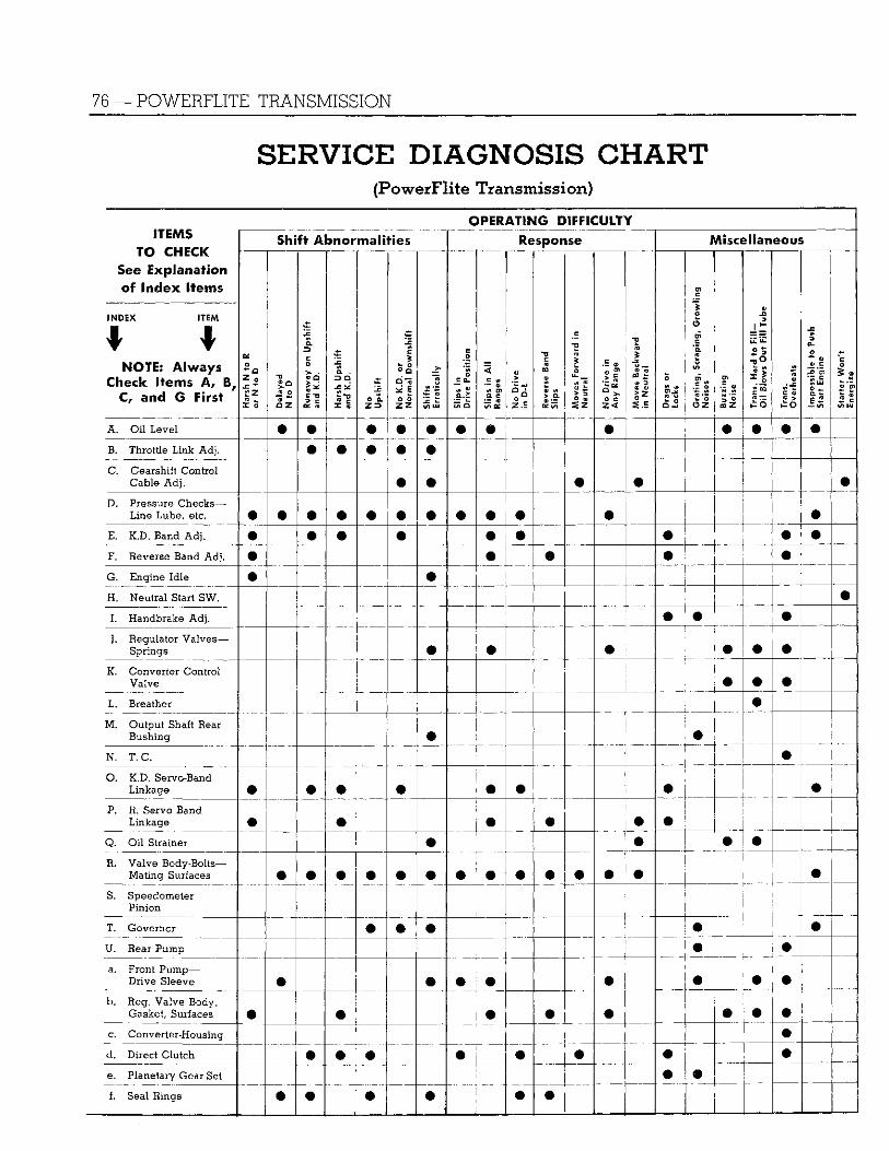
76 — POWERFLITE TRANSMISSION
S E R V I C E DIAGNOSIS CHART (PowerFlite Transmission)
O P E R A T I N G DIFFICULTY STEMS
T O CHICK See E x p l a n a t i o n of I n d e x I t e m s
INDEX ITEM
NOTE: A l w a y s Check Items A, B #
C, and G F i r s t
Shift Abnormal i t i e s Response Miscel laneous STEMS T O CHICK
See E x p l a n a t i o n of I n d e x I t e m s
INDEX ITEM
NOTE: A l w a y s Check Items A, B #
C, and G F i r s t Hars
h N
to
R or
N t
o D
Dela
yed
N t
o D
Runa
way
on
Upsh
ift
and
K.D.
Hars
h Up
shift
an
d K
D.
No
Upsh
ift
No K
.D.
or
Nor
mal
Dow
nshi
ft
Shift
s Er
ratic
ally
Slip
s in
D
rive
Posi
tion
Slip
s in
All
Rang
es
No D
rive
in D
-L
Reve
rse
Band
Sl
ips
Mov
es F
orw
ard
in
Neu
tral
No D
rive
in
Any
Ran
ge
Mov
es B
ackw
ard
in N
eutra
l
Drag
s or
Lo
cks
Gra
ting,
Scr
apin
g, G
row
ling
Noi
ses
Buzz
ing
Noi
se
Tran
s. H
ard
to F
ill-
Oil
Blow
s O
ut F
ill T
ube
Tran
s.
Ove
rhea
ts
l Im
poss
ible
to
Push
1
Star
t Eng
ine
Star
ter
Won
't En
ergi
ze
A. Oil Level m • • • • • m • #
B. Throttle L i n k Adj. • # • • C. G e a r s h i f t C o n t r o l
Cable Adj. • • D. Pressure Checks—
Line Lube, etc. m m m • ® m • • o • E. K.D. Band Adj. * m m • • • % • • F. Reverse Band Adj. • • G. Engine Idle H. Neutral Start SW. I . Handbrake Adj. # • J. Regulator Valves—
Springs m I • •
K. Converter Control Valve • • •
L. Breather • M . Output Shaft Rear
Bushing • • N. T.C. • O. K.D. Servo-Band
Linkage • m m • # • • P. R. Servo Band
Linkage • m • • • m Q. Oil Strainer • • # • R. Valve Body-Bolts—
Mating Surfaces m m m • • # • • • m • • S. Speedometer
Pinion i
T. Governor # • • • • U. Rear Pump • • a. Front Pump—
Drive Sleeve o m • • • b. Reg. Valve Body,
Gasket, Surfaces • m j # • m • • #
c. Converter-Housing j • d. Direct Clutch m • m • m • e. Planetary Gear Set 1 m • f. Seal Rings • m # • |
! m ®
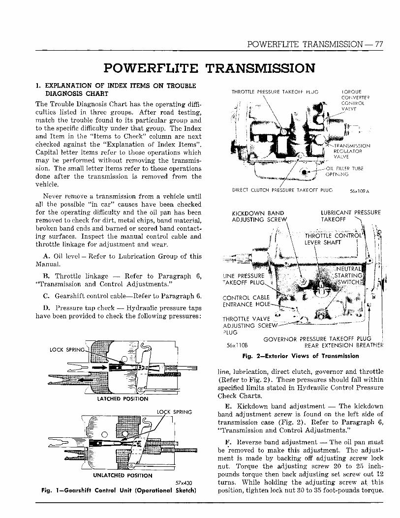
POWERFLITE TRANSMISSION—77
P O W E R F L I T E TRANSMISSION 1. EXPLANATION OF INDEX ITEMS O N TROUBLE
DIAGNOSIS CHA1T
The Trouble Diagnosis Char t has the operating difficulties l isted i n three groups. A f t e r road test ing, match the trouble found to i ts par t icular group and to the specific difficulty under t h a t group. The Index and I t e m i n the "I tems to Check" column are next checked against the "Explanat ion of Index I tems". Capital le t ter i tems refer to those operations which m a y be performed w i t h o u t removing the transmission. The small le t ter i tems refer to those operations done after the transmission is removed f r o m the vehicle.
Never remove a transmission f r o m a vehicle u n t i l a l l the possible " i n car" causes have been checked fo r the operating difficulty and the oil pan has been removed to check fo r d i r t , metal chips, band mater ia l , broken band ends and burned or scored band contacti n g surfaces. Inspect the manual control cable and th ro t t l e l inkage fo r adjustment and wear.
THROTTLE PRESSURE TAKEOFF PLUG
A . Oi l level • Manual .
Refer to Lubr ica t ion Group of th i s
B . Thro t t l e l inkage — Refer to Paragraph 6, "Transmission and Control Adjus tments ."
C. Gearshift control cable—Refer to Paragraph 6.
D . Pressure tap check — Hydrau l ic pressure taps have been provided to check the fo l lowing pressures:
LATCHED POSITION
LOCK SPRING
UNLATCHED POS IT ION
57x430
Fig. 1—Gearshift Control Unit (Operational Sketch)
T O R Q U E
C O N V E R T E R
C O N T R O L
7/ L V E
• T R A N S M I S S I O N
REGULATOR V A L V E
- O ; L F ILLER T U B E
O P E N I N G
DIRECT CLUTCH PRESSURE TAKEOFF PLUG 56x109 A
KICKDOWN BAND ADJUSTING S C R E W
LUBRICANT PRESSURE . TAKEOFF ^
THROTTLE C O N T R O L 0
LEVER S H A F T
N E U T R A L S T A R T ; \ G J N E P R E S S U R E
" A K E O F F P L U G
C O N T R O L C A B L E E N T R A N C E H O L E -
T H R O T T L E V A L V E A D J U S T I N G S C R E W - """ ?LUG
GOVERNOR P R E S S U R E T A K E O F F P L U G 56x110B REAR E X T E N S I O N BREATHER
Fig, 2—Exterior V iews of Transmission
line, lubr icat ion, direct clutch, governor and t h ro t t l e (Refer to F i g . 2 ) . These pressures should fa l l w i t h i n specified l i m i t s stated i n Hydrau l ic Control Pressure Check Charts.
E . K ickdown band adjustment — The k ickdown band adjustment screw is found on the lef t side of transmission case ( F i g . 2 ) . Refer to Paragraph 6, "Transmission and Control Adjus tments ."
F . Reverse band adjustment — The oi l pan must be removed to make th is adjustment. The adjustment is made by backing off adjus t ing screw lock nut . Torque the adjus t ing screw 20 to 25 inch-pounds torque then back adjus t ing set screw out 12 turns . Whi le holding the adjust ing screw at th i s position, t i gh ten lock nu t 30 to 35 foot-pounds torque.
78 — POWERFLITE TRANSMISSION
G. Engine idle — Ad jus t to 475 to 500 r .p .m.
H . Neutra l s t a r t ing switch — Check wi re connections and switch.
N O T E : I f jumper wi re is used for cranking engine (when tak ing compression readings, etc.) i t is i m por tant tha t jumper leads be connected to ba t te ry terminals and to s tar ter swi tch te rmina l (located toward rear of car) of the solenoid.
I . Handbrake—Check for excessive drag. A d j u s t as outlined i n Brakes Group of th is manual.
J. Regulator valve spring — The regulator valve may be removed by removing the regulator valve spr ing retainer which is on the r i g h t side of t ransmission case (F ig . 2 ) . Check for a stuck or scratched valve and/or buckled spring.
K . Converter control valve, spring — The converter control valve may be removed by removing the converter control valve spr ing retainer wh ich is on r i g h t side of transmission case (F ig . 2 ) . Check for a stuck or scratched valve and/or buckled spring.
L . Breather — Check to determine whether breather is free of d i r t , undelegating, etc.
M . Output shaft rear bearing, snap ring—Check for rough bearing and/or unseated snap r ing . Snap rings are available i n two sizes.
N . Torque converter housing cooling air passages — Check for d i r t , mud or other foreign mater ia l on screens or torque converter cooling fins.
O. Kickdown servo, band and linkage — Check for broken seal r ings, stuck servo piston or broken linkage.
P. Reverse servo, band and linkage — Check for t o r n seal, stuck or broken band and/or linkage.
Q. Oil strainer and suction tubes — Check for possible a ir leakage at f ron t pump suction tube, or rear pump suction tube.
R. Valve body a t taching bolts and ma t ing sur
face — Check fo r loose bolts, burrs or scratches on ma t ing surfaces. Clean valve body assembly. Check for stuck valves, d i r t , scratched valves or body and burrs on valves. Torque valve body bolts to specifications.
S. Speedometer pinion — Check nylon teeth for wear, shredding.
T. Governor — Clean assembly and check weight assembly and valve for burrs, scratches or s t icky operation. Examine the governor valve shaft, shaft snap rings and seal r ings.
U . Rear pump — Clean and inspect assembly for side and diametral clearance. Note whether rear oi l pump pinion ball is i n place. Examine output shaft support face for scoring.
a. F ron t pump and drive sleeve — Clean and i n spect assembly for side and diametral clearance. Examine oil pump inner and outer rotor fo r scoring. Check f ron t pump drive sleeve seal r i ng .
b. Regulator valve body, ma t ing surfaces, gasket — Clean and inspect valve body for scratches and scoring on valve bores and face which bears against the f ron t pump housing. Examine valve body to determine i f secondary reaction orifice is free of d i r t . Check gasket for uniformness of compression by valve body.
c. Converter — Flush out converter and check converter hub runout. (Refer to Torque Converter Page.)
d . Direct clutch — Clean and inspect discs, plates, dr ive hub, r e tu rn spring and piston.
e. Planetary gear set — Clean and inspect gear set for w o r n th rus t washers, nicked or rough gear teeth and excessive pinion and clearance.
f. Seal r ings — Check for burrs , broken ends.
N O T E : Refer to Figure 35 for i l lus t ra t ion showing location of the various dri l led passages i n transmission case.
S E R V I C E PROCEDURES 2. OPEHAIiON
PowerFli te combines a h igh ly efficient torque conver ter and a simple automatic two-speed transmission which provides exceptionally smooth performance throughout the entire speed range. The transmission is equipped w i t h a neutral s t a r t ing safe
t y switch which prevents s ta r t ing the car i n gear. A l l normal d r iv ing can be done i n the drive (D) range, which accelerates the car i n low range then automatically upshifts the transmission into direct dr ive at the proper t ime, depending upon the degree of acceleration desired by the driver. The shif t is
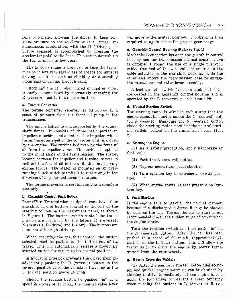
POWERFLITE TRANSMISSION — 79
fu l ly automatic, al lowing the d r iver to keep constant pressure on the accelerator a t a l l times. I n stantaneous acceleration, w i t h the D (Dr ive) push but ton engaged, is accomplished by pressing the accelerator pedal to the floor. This action downshifts the transmission to low gear.
The L (low) range is provided to keep the transmission i n low gear regardless of speeds for unusual d r iv ing conditions such as c l imbing or descending mountains or d r iv ing th rough sand.
"Rocking" the car, when mired i n mud or snow, is easily accomplished by al ternately engaging the R (reverse) and L (low) push buttons.
a. Torque Converter The torque converter receives i t s oi l supply at a constant pressure f rom the f r o n t o i l pump i n the transmission.
The un i t is bolted to and supported by the crankshaft flange. I t consists of three basic par t s : an impeller, a turbine and a stator. The impeller, which forms the outer sh^ll of the converter uni t , is dr iven by the engine. The turbine is dr iven by the force of oil f r o m the impeller vanes. The turb ine is splined to the input shaft of the transmission. The stator, located between the impeller and turbine, serves to redirect the flow of oil i n the uni t , thus m u l t i p l y i n g engine torque. The stator is mounted on an overrunn ing clutch which permits i t to rotate only i n the direction of impeller and turbine ro ta t ion .
The torque converter is serviced only as a complete assembly.
b. Gearshift Control Push Button PowerFli te Transmission equipped cars have four gearshift control buttons located t o the left of the steering column on the inst rument panel, as shown in F igure 1. The buttons, which control the transmission are identified by the let ters R (reverse), N (neut ra l ) , D (drive) and L ( l o w ) . The buttons are i l luminated for n ight dr iv ing .
When operating the gearshift control , the bu t ton selected must be pushed to the f u l l extent of i t s t ravel . This w i l l automatically release a previously selected but ton for re turn to i ts normal position.
A hydraulic interlock prevents the dr iver f r o m i n advertently pushing the R (reverse) but ton to the reverse position when the vehicle is t ravel ing i n the D (drive) position above 15 mph.
Should the reverse but ton be pushed " i n " at a speed in excess of 15 mph., the manual valve lever
w i l l move to the neutral position. The dr iver is then required to again select the proper gear range.
c. Gearshift Control Housing (Refer to Fig. 1) Mechanical connection between the gearshift control housing and the transmission manual control valve is obtained th rough the use of a single push-pull cable. One end of the wi re cable is secured to the cable actuator i n the gearshift housing, while the other end enters the transmission case to engage the manual control valve lever assembly.
A back-up l i g h t switch (when so equipped) is i n corporated i n the gearshift control housing and is operated by the R (reverse) push but ton slide.
d. Neutral Starting Switch The s ta r t ing motor is wi red i n such a way tha t the engine cannot be started unless the N (neutral) button is engaged. Engaging the N (neutral) bu t ton closes the s t a r t i ng motor c i rcui t at the neutral starting switch, located on the transmission case (F ig . 2 ) .
e. Starting the Engine (1 ) As a safety precaution, apply handbrake or
foot brake.
(2 ) Push the N (neutral ) but ton.
(3 ) Depress accelerator pedal s l ight ly .
(4 ) T u r n ign i t ion key to extreme clockwise posit ion.
(5 ) When engine starts, release pressure on i g n i t ion key.
1 Push Starting
I f the engine fails to s ta r t i n the normal manner, because of a discharged bat tery, i t may be started by pushing the car. Towing the car to s tar t is not recommended due to the sudden surge of power when the engine starts .
T u r n the ign i t i on switch on, then push " i n " on the N (neutral) but ton. A f t e r the car has been pushed to a speed of 25 m.p.h. (approximate ly) , push in on the L ( low) but ton. This w i l l allow the transmission to drive the engine by power transmi t ted f rom the rear wheels.
g. How to Drive the Vehicle (1) A f t e r the engine is started, better fuel econo
my and quicker engine w a r m up can be obtained by s ta r t ing to dr ive immediately. I f the engine is cold apply the foot brake to prevent a creep tendency when pushing the buttons i n D (drive) or R (re-
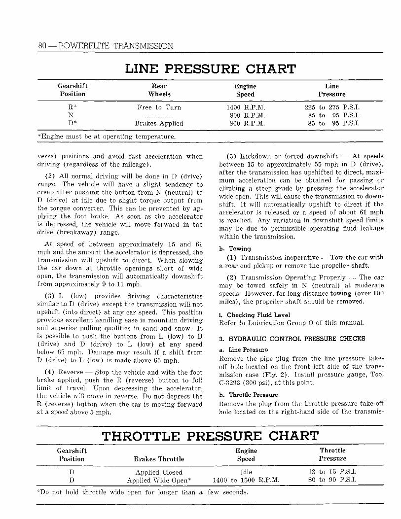
80 —POWERFLITE TRANSMISSION
LINE PRESSURE CHART Gearshift Rear Engine Line Position Wheels Speed Pressure
R* Free to T u r n 1400 R.P.M. 225 to 275 P.S.I. N 800 R.P.M. 85 to 95 P.S.I. D * Brakes Appl ied 800 R.P.M. 85 to 95 P.S.I.
* Engine must be at operating temperature.
verse) positions and avoid fast acceleration when d r i v i n g (regardless of the mileage).
(2) A l l normal d r i v i n g w i l l be done i n D (drive) range. The vehicle w i l l have a s l ight tendency to creep after pushing the but ton f r o m N (neutral) to D (drive) at idle due to s l ight torque output f rom the torque converter. This can be prevented by app ly ing the foot brake. As soon as the accelerator is depressed, the vehicle w i l l move fo rward i n the drive (breakaway) range.
A t speed of between approximately 15 and 61 mph and the amount the accelerator is depressed, the transmission w i l l upshif t to direct. When slowing the car down at th ro t t l e openings shor t , of wide open, the transmission w i l l automatically downshift f r o m approximately 9 to 11 mph.
(3 ) L ( low) provides d r i v i n g characteristics s imilar to D (drive) except the transmission w i l l not upshif t ( into direct) at any car speed. This position provides excellent handling ease i n mounta in d r iv ing and superior pu l l ing qualities i n sand and snow. I t is possible to push the buttons f r o m L ( low) to D (dr ive) and D (dr ive) to L ( low) at any speed below 65 mph. Damage may result i f a sh i f t f r o m D (drive) to L ( low) is made above 65 mph .
(4) Reverse — Stop the vehicle and w i t h the foot brake applied, push the R (reverse) but ton to f u l l l i m i t of t ravel . Upon depressing the accelerator, the vehicle w i l l move i n reverse. Do not depress the R (reverse) bu t ton when the car is moving fo rward at a speed above 5 mph.
(5) K ickdown or forced downshift -— A t speeds between 15 to approximately 55 mph in D (dr ive) , after the transmission has upshifted to direct, max i m u m acceleration can be obtained for passing or cl imbing a steep grade by pressing the accelerator wide open. This w i l l cause the transmission to downshif t . I t w i l l automatically upshif t to direct i f the accelerator is released or a speed of about 61 mph is reached. A n y var ia t ion i n downshift speed l imi t s may be due to permissible operating fluid leakage w i t h i n the transmission,
h. Towing (1) Transmission inoperative — Tow the car w i t h
a rear end pickup or remove the propeller shaft.
(2 ) Transmission Operating Properly — The car may be towed safely in N (neutral) at moderate speeds. However, for long distance towing (over 100 miles) , the propeller shaft should be removed.
L Checking Fluid Level Refer to Lubr ica t ion Group O of this manual.
3. HYDRAULIC CONTIOL PRESSURE CHECKS
a. Line Pressure Remove the pipe plug f rom the line pressure takeoff hole located on the f ron t lef t side of the transmission case (F ig . 2 ) . Ins ta l l pressure gauge, Tool C-3293 (300 ps i ) , at this point .
b. Throttle Pressure Remove the plug f rom the th ro t t l e pressure take-off hole located on the r ight -hand side of the transmis-
T H R O T T L E PRESSURE CHART Gearshift Engine Thro t t l e Position Brakes Thro t t l e Speed Pressure
D Appl ied Closed Idle 13 to 15 P.S.I. D Appl ied Wide Open* 1400 to 1500 R.P.M. 80 to 90 P.S.I.
*Do not hold th ro t t l e wide open for longer than a few seconds.
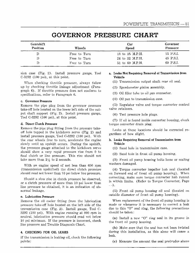
POWERFLITE TRANSMISSION— 81
GOVERNOR PRESSURE CHART Gearshift Car Governor Position Wheels Speed Pressure
D Free to T u r n IS to 15 M . P . H . 15 P.S.I. D Free to T u r n 24 to 82 M . P . H . 45 P.S.I. D Free to T u r n 51 to 60 M.P .H . 60 P.S.L
sion ease (F ig . 2 ) . Ins ta l l pressure gauge, Tool C-3292 (100 ps i ) , at this point .
When checking th ro t t l e pressure, always follow up by checking th ro t t l e l inkage adjustment (Paragraph 6 ) . I f t h ro t t l e pressure does not conform to specifications, refer to Paragraph 6.
c. Governor Pressure Remove the pipe plug f r o m the governor pressure take-off hole located on the lower le f t side of the output shaft support ( F i g . 2 ) . Ins ta l l pressure gauge, Tool C-3292 (100 ps i ) , at th i s point .
d. Direct Clutch Pressure Remove the pipe plug f i t t i n g f r o m the pressure takeoff hole tapped i n the k ickdown servo (F ig . 2) and instal l pressure gauge, Tool C-3292 (100 ps i ) . W i t h the rear wheels free to t u r n , accelerate the engine slowly u n t i l an upshift occurs. D u r i n g the upshift , the pressure gauge attached to the k ickdown servo should show a very rapid pressure rise f r o m 0 to final clutch or line pressure. This rise should not take more than ll/2 to 2 seconds.
W i t h an engine speed of not less than 650 r p m (transmission upshifted) the direct clutch pressure should read not lower than 10 psi below line pressure.
Should a slow rise i n clutch pressure be observed, or a clutch pressure of more than 10 psi lower t han line pressure be obtained, i t is an indicat ion of abnormal leakage.
e. Lubrication Pressure Remove the oil cooler f i t t i ng f r o m the lubr icat ion pressure take-off hole located on the lef t side of the transmission case ( F i g . 2 ) . Ins ta l l gauge, Tool C-3292 (100 ps i ) . W i t h engine runn ing at 800 r p m In neutral , lubr icat ion pressure should read not below 10 psi m i n i m u m . I f the pressure Is Incorrect, check line pressure and Trouble Diagnosis Chart ,
4. CHECKING FOR OIL LEAKS
I f the transmission Is leaking oi l , check the fo l lowing points :
a. Leaks Not Requiring Removal of Transmission from Vehicle
(1) Transmission output shaft rear oil seal.
(2) Speedometer pinion assembly.
(3) Oil filler tube to oil pan connector.
(4) Oil pan to transmission case.
(5 ) Regulator valve and torque converter control valve retainers.
(6 ) Test pressure hole plugs.
(7 ) I f oil is found inside converter housing, check torque converter dra in plug.
Leaks at these locations should be corrected regardless of how sl ight .
b. Leaks Requiring Removal of Transmission from Vehicle
(1 ) Sand hole i n transmission case.
(2 ) Sand hole i n f ron t oil pump housing.
(3 ) F ron t oi l pump housing bolts loose or sealing washers damaged.
(4) Torque converter impeller hub seal (located on fo rward end of f ron t oi l pump housing) . When correcting, make sure torque converter hub runout is w i t h i n l imi t s . (Refer to Torque Converter, Page — ) .
(5 ) F ron t oil pump housing oi l seal (located on outside diameter of f ron t oi l pump housing) .
When replacement of the f ron t oi l pump housing is made or whenever i t is necessary to correct a leak due to th is " O " seal r i ng , the fo l lowing precautions should be taken:
( a ) Ins ta l l a new " O " r i n g seal i n i t s groove i n the f ron t oil pump housing.
(b ) Make sure t ha t the seal has not been twis ted dur ing th is instal lat ion, as th is alone w i l l cause a leak.
(c) Measure the amount the seal protrudes above
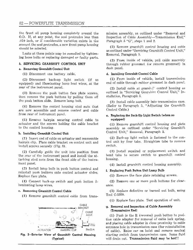
82 — POWERFLITE TRANSMISSION
the f ron t oi l pump housing completely around the O.D. I f , at any point, the seal protrudes less than .010 inch, or i f considerable var ia t ion exists i n the amount the seal protrudes, a new f ront pump housing should be selected.
Leaks at these points may be remedied by t igh tening loose bolts or replacing damaged or fau l ty parts.
5. SERVICING GEARSHIFT CONTROL UNIT
a. Removing Gearshift Control Unit
(1 ) Disconnect one bat tery cable.
(2 ) Disconnect back-up l i g h t switch ( i f so equipped) and i l l umina t ing lamp lead wires, at the rear of the ins t rument panel.
(3 ) Remove the push but ton face plate screws, then remove the push buttons by pul l ing them off the push bu t ton slide. Remove lamp bolt.
(4 ) Remove the control housing stud nuts tha t are now accessible and remove control and cable f r o m rear of ins t rument panel.
(5 ) Remove ha i rp in securing control cable to actuator and the screws holding the cable bracket to the control housing.
b. Installing Gearshift Control Unit
(1 ) Inser t end of cable on actuator and reassemble ha i rp in clip. Place cable bracket on control un i t and ins ta l l screws securely (F ig . 3 ) .
(2) Carefully guide the un i t into position f rom the rear of the ins t rument panel and instal l the attaching s tud nuts f rom the f ron t side of the ins t ru ment panel.
(3 ) Ins ta l l lamp bulb i n push bu t ton control and reinstal l push buttons onto control actuator slides. Replace face plate.
(4) Connect back-up switch and push but ton i l lumina t ing lamp wires.
c. Removing Gearshift Control Cable
(1 ) Remove gearshift control cable f rom trans-
CABLE i B R A C K E T
/ C A B L E . / ASSY .
^ ^ ^ ^ A C T U A T O R ^ HAiRP^CLIP 56x55 A
Fig. 3—Exterior V iew of Gearshift Control Housing (Typical)
mission assembly, as outlined under "Removal and Inspection of Cable Assembly—Transmission End," Paragraph 5 " G " , steps 1 and 2.
(2) Remove gearshift control housing and cable as outlined under "Servicing Gearshift Control U n i t , " Removal, Paragraph 5.
(3 ) F rom inside of vehicle, pul l cable assembly th rough rubber grommet (or remove grommet) i n dash panel.
d. Installing Gearshift Control Cable
(1) F r o m inside of vehicle, instal l transmission end of cable through rubber grommet in dash panel.
(2) Insta l l cable at gearsh i f control housing as outlined i n "Servicing Gearshift Control U n i t , " I n stallation, Paragraph 5.
(3 ) Ins ta l l cable assembly into transmission case. (Refer to Paragraph 5, " A d j u s t i n g the Gearshift Control Cable.)
e. Replacing the Back-Up Light Switch (when so equipped)
(1 ) Remove gearshift control housing and plate assembly as outlined under "Servicing Gearshift Control U n i t , " Removal, Paragraph 5.
(2 ) Back-up l i gh t switch is fastened to the cont r o l un i t by four tabs. Straighten tabs to remove switch.
(3 ) Ins ta l l repaired or replacement switch and bend tabs to secure switch to gearshift control housing.
(4) Ins ta l l gearshift control housing assembly.
f. Replacing Push Button Unit Lamp Bulb
(1) Remove the face plate re ta in ing screws.
(2) Remove one or more push buttons for clearance.
(3) Replace defective or burned out bulb, using Tool C-3399.
(4 ) Replace face plate. Test operation of uni t .
g. Removal and Inspection of Cable Assembly (Transmission End)
(1) Push i n the R (reverse) push bu t ton to posit i on cable adapter for removal of cable lock spring, and placing cable adapter i n close p r o x i m i t y to cable entrance hole i n transmission case ( for reinstal lat ion of cable). Raise car on hoist and remove neutral s t a r t ing switch f rom transmission case. Some fluid w i l l dra in out. Transmission fluid may be ho t ! I
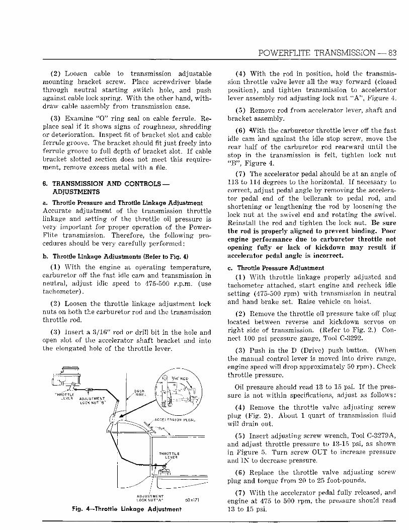
POWERFLITE TRANSMISSION — 83
(2 ) Loosen cable to transmission adjustable mount ing bracket screw. Place screwdriver blade th rough neutral s t a r t ing switch hole, and push against cable lock spring. W i t h the other hand, w i t h draw cable assembly f r o m transmission case.
(3) Examine " 0 " r i n g seal on cable ferrule. Replace seal i f i t shows signs of roughness, shredding or deterioration. Inspect f i t of bracket slot and cable ferrule groove. The bracket should f i t j u s t freely into ferrule groove to f u l l depth of bracket slot. I f cable bracket slotted section does not meet this requirement, remove excess metal w i t h a file.
6. TRANSMISSION AND CONTROLS — ADJUSTMENTS
a. Throttle Pressure and Throttle Linkage Adjustment Accurate adjustment of the transmission th ro t t l e linkage and set t ing of the th ro t t l e oi l pressure is very impor tan t for proper operation of the PowerFl i t e transmission. Therefore, the fo l lowing procedures should be very carefully performed:
b. Throttle Linkage Adjustments (Refer to Fig. 4)
(1 ) W i t h the engine at operating temperature, carburetor off the fast idle cam and transmission i n neutral , adjust idle speed to 475-500 r .p .m. (use tachometer) .
(2 ) Loosen the th ro t t l e linkage adjustment lock nuts on both the carburetor rod and the transmission th ro t t l e rod.
(3 ) Insert a 3/16" rod or d r i l l b i t i n the hole and open slot of the accelerator shaft bracket and in to the elongated hole of the t h ro t t l e lever.
ADJUSTMENT LOCK NUT " A " 60x171
Fig. 4—Throttle Linkage Adjustment
(4 ) W i t h the rod i n position, hold the transmission th ro t t l e valve lever all the way fo rward (closed posi t ion) , and t igh ten transmission to accelerator lever assembly rod adjust ing lock nut " A " , Figure 4.
(5 ) Remove rod f r o m accelerator lever, shaft and bracket assembly.
(6 ) W i t h the carburetor t h ro t t l e lever off the fast idle cam and against the idle stop screw, move the rear ha l f of the carburetor rod rearward u n t i l the stop i n the transmission is fel t , t ighten lock nu t " B " , F igure 4.
(7 ) The accelerator pedal should be at an angle of 113 to 114 degrees to the horizontal . I f necessary to correct, adjust pedal angle by removing the accelerato r pedal end of the bellcrank to pedal rod, and shortening or lengthening the rod by loosening the lock nu t at the swivel end and ro ta t ing the swivel . Reinstall the rod and t igh ten the lock nut. Be sure the rod is properly aligned to prevent binding. Poor engine performance due to carburetor throttle not opening fully or lack of kickdown may result if accelerator pedal angle is incorrect.
c. Throttle Pressure Adjustment (1 ) W i t h th ro t t l e linkage properly adjusted and
tachometer attached, s ta r t engine and recheck idle se t t ing (475-500 rpm) w i t h transmission i n neutral and hand brake set. Raise vehicle on hoist.
(2 ) Remove the th ro t t l e oil pressure take off plug located between reverse and kickdown servos on r i g h t side of transmission. (Refer to F ig . 2.) Connect 100 psi pressure gauge, Tool C-3292.
(3) Push i n the D (Dr ive) push but ton. (When the manual control lever is moved into drive range, engine speed w i l l drop approximately 50 r p m ) . Check th ro t t l e pressure.
Oil pressure should read 13 to 15 psi. I f the pressure is not w i t h i n specifications, adjust as fol lows:
(4 ) Remove the th ro t t l e valve adjust ing screw plug (F ig . 2 ) . Abou t 1 quart of transmission fluid w i l l d ra in out.
(5 ) Insert adjust ing screw wrench, Tool C-3279A, and adjust t h ro t t l e pressure to 13-15 psi, as shown i n F igure 5. T u r n screw OUT to increase pressure and I N to decrease pressure.
(6 ) Replace the th ro t t l e valve adjust ing screw plug and torque f r o m 20 to 25 foot-pounds.
(7 ) W i t h the accelerator pedal fu l ly released, and engine at 475 to 500 rpm, the pressure should read 13 to 15 psi.
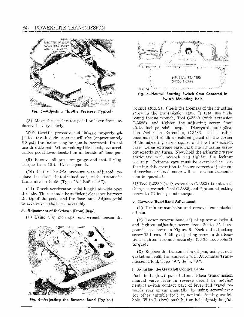
84 — POWERFLITE TRANSMISSION
Fig. 5—Adjusting Throt t le Pressure (Typical)
(8 ) Move the accelerator pedal or lever f r o m underneath, very slowly.
W i t h t h ro t t l e pressure and linkage properly adjusted, the t h ro t t l e pressure w i l l rise (approximately 6-8 psi) the ins tant engine r p m Is increased. Do not use th ro t t l e rod. When mak ing this check, use accelerator pedal lever located on underside of floor pan.
(9) Remove oil pressure gauge and ins ta l l plug. Torque f r o m 10 to 12 foot-pounds.
(10) I f the th ro t t l e pressure was adjusted, replace the fluid t ha t drained out, w i t h Automat ic Transmission F l u i d (Type " A " , Suffix " A " ) .
(11) Check accelerator pedal height at wide open th ro t t l e . There should be sufficient clearance between the t i p of the pedal and the floor mat . Ad jus t pedal to accelerator shaft rod assembly.
d. Adjustment of Kickdown (Front) Band
(1 ) Us ing a % inch open-end wrench loosen the
Fig. 6—Adjusting the Reverse l a n d (Typical)
NEUTRAL STARTER SWITCH C A M
Fig. 7—Neutral S tor t ing Switch Cam Centered in Switch M o u n t i n g Hole
locknut (F ig . 2 ) . Check the freeness of the adjust ing screw i n the transmission case. I f free, use inch-pound torque wrench, Tool C-3380 ( w i t h extension C-3583), and t igh ten the adjust ing screw f r o m 40-43 inch-pounds* torque. Disregard mul t ip l icat i on factor on Extension, C-3583. Use a reference mark of chalk or colored pencil on the corner of the adjust ing screw square and the transmission case. Using extreme care, back the adjust ing sc^ew out exactly 2% turns. Now, hold the adjust ing screw stat ionary w i t h wrench and t igh ten the locknut securely. Ext reme care must be exercised i n perfo rming th is operation to insure correct adjustment otherwise serious damage w i l l occur when transmission is operated.
* I f Tool C-3380 ( w i t h extension C-3583) Is not used, then, use wrench, Tool C-3380, and t igh ten adjust ing screw to 72 inch-pounds torque.
ee Reverse (Bear) Band Ad jus tmen t
(1) Dra in transmission and remove transmission oi l pan.
(2) Loosen reverse band adjust ing screw locknut and t igh ten adjust ing screw f r o m 20 to 25 inch-pounds, as shown i n Figure 6. Rack out adjus t ing screw 12 turns . Hold ing adjust ing screw i n th is locat ion, t igh ten locknut securely (30-35 foot-pounds torque) .
(3 ) Replace the transmission oi l pan, using a new gasket and refil l transmission w i t h Automat ic Transmission F lu id , Type " A " , Suffix " A " .
f. Adjusting the Gearshift Control Cable
Push i n L ( low) push but ton. Place transmission manual valve lever i n reverse detent by moving neutral switch contact par t of lever f u l l t r ave l towards rear of car manually, by using screwdriver (or other suitable tool) i n neutral s t a r t ing swi tch hole. W i t h L (low) push bu t ton held t i g h t l y i n ( f u l l
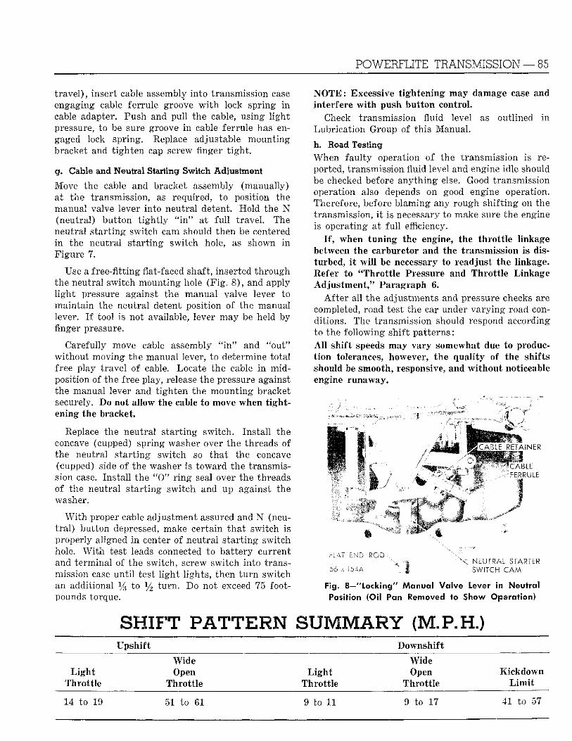
POWERFLITE TRANSMISSION — 85
t rave l ) , insert cable assembly in to transmission case engaging cable ferrule groove w i t h lock spring i n cable adapter. Push and pul l the cable, using l i gh t pressure, to be sure groove i n cable ferrule has engaged lock spring. Replace adjustable mount ing bracket and t igh ten cap screw finger t i g h t .
g. Cable and Neutral Starting Switch Adjustment
Move the cable and bracket assembly (manually) at the transmission, as required, to position the manual valve lever in to neutral detent. Hold the N (neutral) bu t ton t i g h t l y " i n " at f u l l t ravel . The neutral s t a r t ing switch cam should then be centered i n the neutral s ta r t ing switch hole, as shown i n Figure 7.
Use a f ree-f i t t ing flat-faced shaft, inserted th rough the neutral switch mount ing hole (F ig . 8 ) , and apply l i gh t pressure against the manual valve lever to mainta in the neutral detent position of the manual lever. I f tool is not available, lever may be held by finger pressure.
Carefully move cable assembly " i n " and "out" w i thou t moving the manual lever, to determine to ta l free play t ravel of cable. Locate the cable i n mid -position of the free play, release the pressure against the manual lever and t igh ten the moun t ing bracket securely. Do not allow the cable to move when tightening the bracket.
Replace the neutra l s t a r t ing swi tch . Ins ta l l the concave (cupped) spring washer over the threads of the neutral s t a r t ing switch so tha t the concave (cupped) side of the washer is toward the transmission case. Ins ta l l the " 0 " r i n g seal over the threads of the neutral s t a r t ing swi tch and up against the washer.
W i t h proper cable adjustment assured and N (neut ra l ) bu t ton depressed, make certain tha t switch is properly aligned i n center of neutra l s t a r t ing switch hole. W i t h test leads connected to ba t te ry current and terminal of the switch, screw switch into transmission case u n t i l test l i gh t l ights , then t u r n switch an additional l / s to y2 t u r n . Do not exceed 75 footpounds torque.
N O T E : Excessive tightening may damage case and interfere with push button control.
Check transmission fluid level as outlined i n Lubr ica t ion Group of th is Manual.
h. Road Testing When fau l ty operation of the transmission is reported, transmission fluid level and engine idle should be checked before any th ing else. Good transmission operation also depends on good engine operation. Therefore, before blaming any rough sh i f t ing on the transmission, i t is necessary to make sure the engine is operating at f u l l efficiency.
If, when tuning the engine, the throttle linkage between the carburetor and the transmission is disturbed, it will be necessary to readjust the linkage. Refer to "Throttle Pressure and Throttle Linkage Adjustment," Paragraph 6.
A f t e r all the adjustments and pressure checks are completed, road test the car under v a r y i n g road conditions. The transmission should respond according to the fo l lowing shi f t pa t terns : All shift speeds may vary somewhat due to production tolerances, however, the quality of the shifts should be smooth, responsive, and without noticeable engine runaway.
• PS • l
g C A B l £ RETAINER
FERRULE
56 x ",54A x NEUTRAL STARTER
SWITCH CAM
Fig. 8—"Locking" Manual Valve Lever in Neutral Position (Oil Pan Removed fro Show Operation)
F r p p g m ^ i J&a aaa I3M sate tJsi C J U B
Upshift Downshift
Light Throttle
Wide Open
Throttle Light
Throttle
Wide Open
Throttle Kickdown
Limit
14 to 19 51 to 61 9 to 11 9 to 17 41 to 57
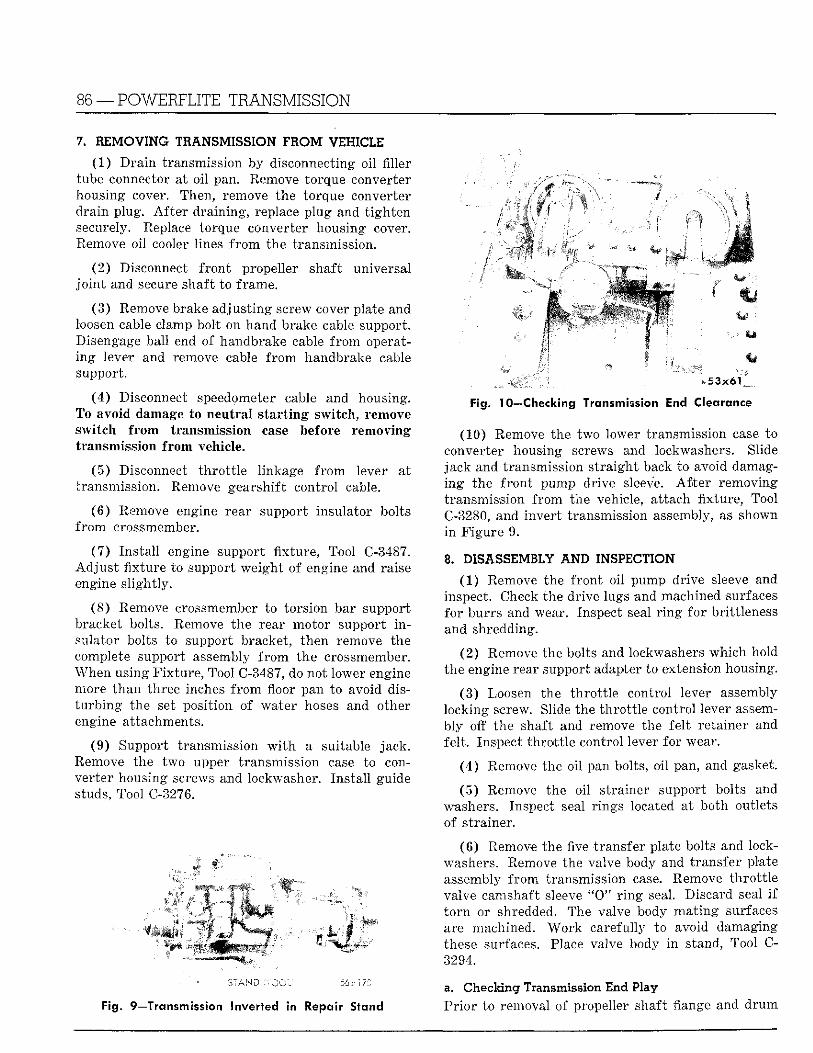
86 —POWERFLITE TRANSMISSION
? 0 REMOVING TRANSMISSION FROM VEHICLE
(1) D r a i n transmission by disconnecting oi l fil ler tube connector at o i l pan. Remove torque converter housing cover. Then, remove the torque converter dra in plug. A f t e r draining, replace p lug and t igh ten securely. Replace torque converter housing cover. Remove oil cooler lines f r o m the transmission.
(2) Disconnect f ron t propeller shaft universal j o i n t and secure shaft to frame.
(3) Remove brake adjust ing screw cover plate and loosen cable clamp bolt on hand brake cable support. Disengage ball end of handbrake cable f r o m operating lever and remove cable f r o m handbrake cable support.
(4) Disconnect speedometer cable and housing. To avoid damage to neutral starting switch, remove switch from transmission case before removing transmission from vehicle.
(5) Disconnect th ro t t l e l inkage f r o m lever at transmission. Remove gearshift control cable.
(6) Remove engine rear support insulator bolts f r o m crossmember.
(7 ) Ins ta l l engine support f ix ture , Tool C-3487. Ad jus t f ixture to support weight of engine and raise engine s l ight ly .
(8 ) Remove crossmember to torsion bar support bracket bolts. Remove the rear motor support i n sulator bolts to support bracket, then remove the complete support assembly f r o m the crossmember. When using F ix tu re , Tool C-3487, do not lower engine more than three inches f r o m floor pan to avoid dist u r b i n g the set position of water hoses and other engine attachments.
(9) Support transmission w i t h a suitable jack. Remove the two upper transmission case to converter housing screws and lockwasher. Ins ta l l guide studs, Tool C-3276.
i
Fig. 10—Checking Transmission End Clearance
(10) Remove the two lower transmission case to converter housing screws and lockwashers. Slide jack and transmission s t ra ight back to avoid damaging the f ron t pump drive sleeve. A f t e r removing transmission f r o m the vehicle, at tach f ixture, Tool C-3280, and inver t transmission assembly, as shown i n F igure 9.
8. DISASSEMBLY AND INSPECTION
(1 ) Remove the f ron t o i l pump drive sleeve and inspect. Check the drive lugs and machined surfaces for burrs and wear. Inspect seal r i n g for brittleness and shredding.
(2 ) Remove the bolts and lockwashers which hold the engine rear support adapter to extension housing.
(3 ) Loosen the th ro t t l e control lever assembly locking screw. Slide the th ro t t l e control lever assembly off the shaft and remove the fe l t retainer and fel t . Inspect th ro t t l e control lever for wear.
(4 ) Remove the oil pan bolts, oi l pan, and gasket.
(5 ) Remove the oil strainer support bolts and washers. Inspect seal r ings located at both outlets of strainer.
(6 ) Remove the five transfer plate bolts and lockwashers. Remove the valve body and transfer plate assembly f r o m transmission case. Remove th ro t t l e valve camshaft sleeve " 0 " r i n g seal. Discard seal i f t o r n or shredded. The valve body ma t ing surfaces are machined. W o r k carefully to avoid damaging these surfaces. Place valve body i n stand, Tool C-3294.
Fig. 9—Transmission Inverted in Repair Stand
a. Checking Transmission End Play Pr io r to removal of propeller shaft flange and d rum
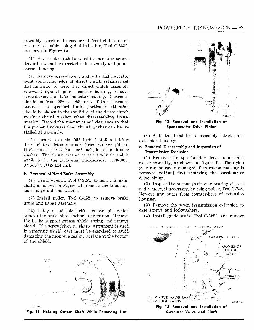
POWERFLITE TRANSMISSION — 87
assembly, check end clearance of f ron t clutch piston retainer assembly using dial indicator, Tool C-3339, as shown i n Figure 10.
(1) P r y f ron t clutch fo rward by inser t ing screwdr iver between the direct clutch assembly and pinion carrier housing.
(2) Remove screwdriver; and w i t h dial indicator point contacting edge of direct clutch retainer, set dial indicator to zero. P r y direct clutch assembly rearward against pinion carrier housing, remove screwdriver, and take indicator reading. Clearance should be f r o m .026 to .052 inch. I f th is clearance exceeds the specified l i m i t , par t icular at tent ion should be shown to the condition of the direct clutch retainer t h rus t washer when disassembling transmission. Record the amount of end clearance so tha t the proper thickness fiber t h rus t washer can be i n stalled at assembly. '
I f clearance exceeds .052 inch, instal l a th icker direct clutch piston retainer th rus t washer ( f iber) . I f clearance is less than .026 inch, ins ta l l a th inner washer. The th rus t washer is selectively fit and is available i n the fo l lowing thicknesses: .078-.080, .095-.097, .112-.114 inch.
b. Removal of Hand Brake Assembly
(1 ) Us ing wrench, Tool C-3281, to hold the main-shaft, as shown i n F igure 11, remove the transmission flange nu t and washer.
(2 ) Ins ta l l puller, Tool C-452, to remove brake d rum and flange assembly.
(3) Us ing a suitable d r i f t , remove p in which secures the brake shoe anchor i n extension. Remove the brake support grease shield spring and remove shield. I f a screwdriver or sharp ins t rument is used i n removing shield, care mus t be exercised to avoid damaging the neoprene sealing surface at the bot tom of the shield.
TOOL
57v98
Fig. 11—Holding Output Shaft While Removing Nut
^ 53x60 Fig. 12—Removal and Installation of
Speedometer Drive Pinion
(4) Slide the hand brake assembly intact f r o m extension housing. c. Removal, Disassembly and Inspection of
Transmission Extension (1 ) Remove the speedometer drive pinion and
sleeve assembly, as shown i n Figure 12. The nylon gear can be easily damaged if extension housing is removed without first removing the speedometer drive pinion.
(2 ) Inspect the output shaft rear bearing oil seal and remove, i f necessary, by using puller, Tool C-748. Remove any burrs f r o m counter-bore of extension housing.
(3) Remove the seven transmission extension to case screws and lockwashers.
(4) Ins ta l l guide studs, Tool C-3283, and remove
O J TP J T SHATT SUPPORT PCT/*-N N'G SCRfcv.
G O V E R N O R BODY
; G O V E R N O R LOCAT ING
•f SCREW
GOVERNOR VALVE SHA-T ~ _ — - r . *
G O V E R N O R V A L V E — — ^ . 5 3 X 1 3 A
Fig. 13—Removal and Installation of Governor Valve and Shaft
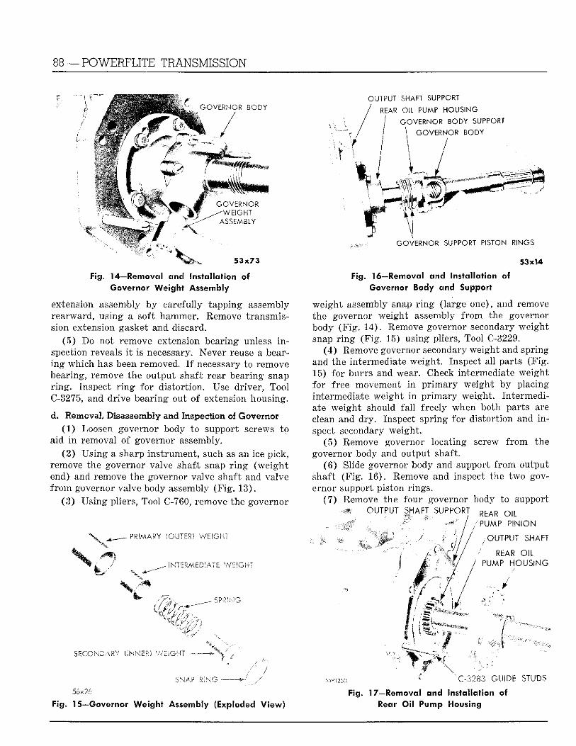
88 —POWERFLITE TRANSMISSION
GOVERNOR BODY
G O V E R N O R ^ - W E I G H T
ASSEMBLY
5 3 x 7 3
Fig. 14—Removal and Installation of Governor Weight Assembly
extension assembly by carefully tapping assembly rearward, using a soft hammer. Remove t ransmission extension gasket and discard.
(5 ) Do not remove extension bearing unless i n spection reveals i t is necessary. Never reuse a bearing which has been removed. I f necessary to remove bearing, remove the output shaft rear bearing snap r i n g . Inspect r i n g for dis tor t ion. Use driver, Tool C-3275, and drive bearing out of extension housing.
d. Removal, Disassembly and Inspection of Governor (1) Loosen governor body to support screws to
aid i n removal of governor assembly. (2 ) Us ing a sharp ins t rument , such as an ice pick,
remove the governor valve shaft snap r i n g (weigh t end) and remove the governor valve shaft and valve f r o m governor valve body assembly (F ig . 13) .
(3) Using pliers, Tool C-760, remove the governor
(CUTER) WEIGHT
I N T E R M E D I A T E WEIG.-T
OUTPUT SHAFT SUPPORT
REAR OIL PUMP HOUSING
GOVERNOR BODY SUPPORT
GOVERNOR BODY
GOVERNOR SUPPORT PISTON RINGS
53x14 Fig. 16—Removal and Installation of
Governor Body and Support
weight assembly snap r i n g (large one), and remove the governor weight assembly f r o m the governor body (F ig . 14) . Remove governor secondary weight snap r i n g (F ig . 15) using pliers, Tool C-3229.
(4 ) Remove governor secondary weight and spring and the intermediate weight . Inspect all parts (F ig . 15) for burrs and wear. Check intermediate weight for free movement i n p r imary weight by placing intermediate weigh t i n p r imary weight . In termediate weight should fa l l freely when both parts are clean and dry . Inspect spr ing for dis tor t ion and i n spect secondary weight .
(5 ) Remove governor locating screw f r o m the governor body and output shaft.
(6 ) Slide governor body and support f r o m output shaft (F ig . 16) . Remove and inspect the two governor support piston rings.
(7 ) Remove the four governor body to support OUTPUT SHAFT S U P P O R T R f c A R Q J L
'PUMP PINION
/OUTPUT SHAFT
REAR OIL PUMP. HOUSING
S?.*ING
SECONDARY (INNER) WEIGHT •
SNAP I v G .56x26
Fig. 15—Governor Weight Assembly (Exploded View)
wvm ' 'C-3283 GUIDE STUDS Fig. 17—Removal and Installation of
Rear Oil Pump Housing
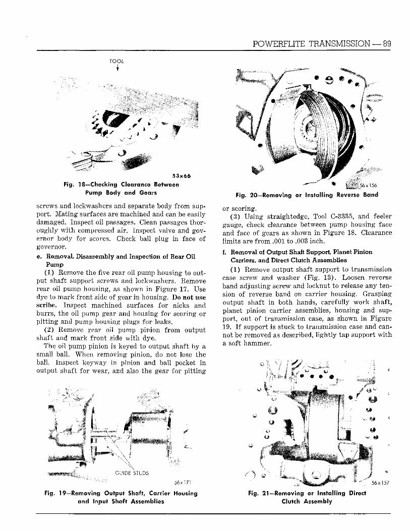
TOOL
POWERFLITE TRANSMISSION — 89
^ 5 3 x 6 6
Fig. 18—Checking Clearance Between _ Pump Body and Gears
screws and lockwashers and separate body f r o m support . M a t i n g surfaces are machined and can be easily damaged. Inspect o i l passages. Clean passages thoroughly w i t h compressed air. Inspect valve and governor body for scores. Check ball p lug i n face of governor. e. Removal, Disassembly and Inspection of Rear O i l
Pump (1) Remove the five rear oil pump housing to out
put shaft support screws and lockwashers. Remove rear oi l pump housing, as shown i n Figure 17. Use dye to mark f ron t side of gear i n housing. Bo not use scribe. Inspect machined surfaces for nicks and burrs, the oi l pump gear and housing for scoring or p i t t i n g and pump housing plugs fo r leaks.
(2) Remove rear oil pump pinion f r o m output shaft and mark f ron t side w i t h dye.
The oi l pump pinion is keyed to output shaft by a small ball . When removing pinion, do not lose the ball. Inspect keyway i n pinion and ball pocket i n output shaft for 'wear , and also the gear fo r p i t t i n g
56 x "156
Fig. 20—Removing or installing Reverse Band
or scoring. (3 ) Us ing straightedge, Tool C-3335, and feeler
gauge, check clearance between pump housing face and face of gears as shown i n F igure 18. Clearance l i m i t s are f r o m .001 to .003 inch. f. Removal of Output Shaft Support, Planet Pinion
Carriers, and Direct Clutch Assemblies (1) Remove output shaft support to transmission
case screw and washer (F ig . 13) . Loosen reverse band adjust ing screw and locknut to release any tension of reverse band on carr ier housing. Grasping output shaft i n both hands, carefully w o r k shaft, planet p in ion carrier assemblies, housing and support , out of transmission case, as shown i n Figure 19. I f support is stuck to transmission case and cannot be removed as described, l i g h t l y tap support w i t h a soft hammer.
GUIDE STUDS
56x171
Fig. 19—Removing Output Shaft, Carrier Housing and Input Shaft Assemblies
• K
5 6 x 1 5 7
Fig. 21—Removing ©r Installing Direct Clutch Assembly
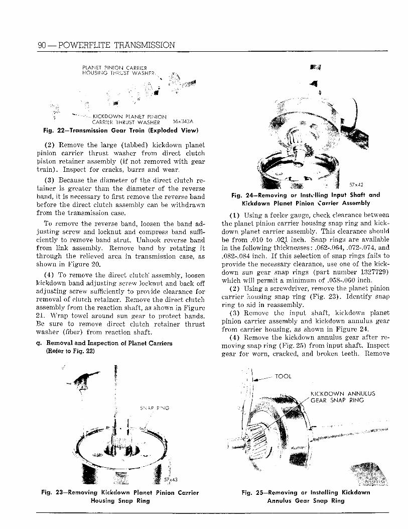
90 —POWERFLITE TRANSMISSION
PLANET PINION CARRiHR HOUSING THRUST WASH.!?
. KICKDOWN PLANET PINION CARRIER THRUST WASHER 56x343A
Fig. 22—Transmission Gear Train (Exploded View)
(2 ) Remove the large (tabbed) k ickdown planet pinion carr ier th rus t washer f r o m direct clutch piston retainer assembly ( i f not removed w i t h gear t r a i n ) . Inspect for cracks, burrs and wear.
(3) Because the diameter of the direct clutch retainer is greater than the diameter of the reverse band, i t is necessary to first remove the reverse band before the direct clutch assembly can be w i t h d r a w n f r o m the transmission case.
To remove the reverse band, loosen the band adj u s t i n g screw and locknut and compress band sufficient ly to remove band s t rut . Unhook reverse band f r o m l ink assembly. Remove band by ro t a t ing i t t h rough the relieved area i n transmission case, as shown i n F igure 20.
(4 ) To remove the direct c lu tch assembly, loosen kickdown band adjust ing screw locknut and back off adjust ing screw sufficiently to provide clearance fo r removal of clutch retainer. Remove the direct clutch assembly f r o m the reaction shaft, as shown in F igure 21 . Wrap towel around sun gear to protect hands. Re sure to remove direct clutch retainer t h ru s t washer (fiber) f r o m reaction shaft.
g. Removal and Inspection of Planet Carriers (Refer to Fig. 22)
Fig. 23—Removing Kickdown Planet Pinion Carrier Housing Snap Ring
r
4
- • ' 57x42
Fig. 24—Removing or Installing Input Shaft and Kickdown Planet Pinion Carrier Assembly
(1 ) Using a feeler gauge, check clearance between the planet pinion carrier housing snap r i n g and kick-down planet carrier assembly. This clearance should be f r o m .010 to .021 inch. Snap rings are available i n the fol lowing thicknesses: .062-.064, .072-.074, and .082-.084 inch. I f th is selection of snap rings fails to provide the necessary clearance, use one of the kick-down sun gear snap rings (par t number 1327729) which w i l l permi t a m i n i m u m of .058-.060 inch.
(2 ) Us ing a screwdriver, remove the planet pinion carr ier housing snap r i n g (F ig . 23) . Ident i fy snap r i n g to aid i n reassembly.
(3 ) Remove the input shaft, kickdown planet pinion carrier assembly and kickdown annulus gear f r o m carrier housing, as shown i n Figure 24.
(4 ) Remove the kickdown annulus gear after removing snap r i n g (F ig . 25) f r o m input shaft. Inspect gear for worn, cracked, and broken teeth. Remove
Fig. 25—Removing or Installing Kickdown Annulus Gear Snap Ring
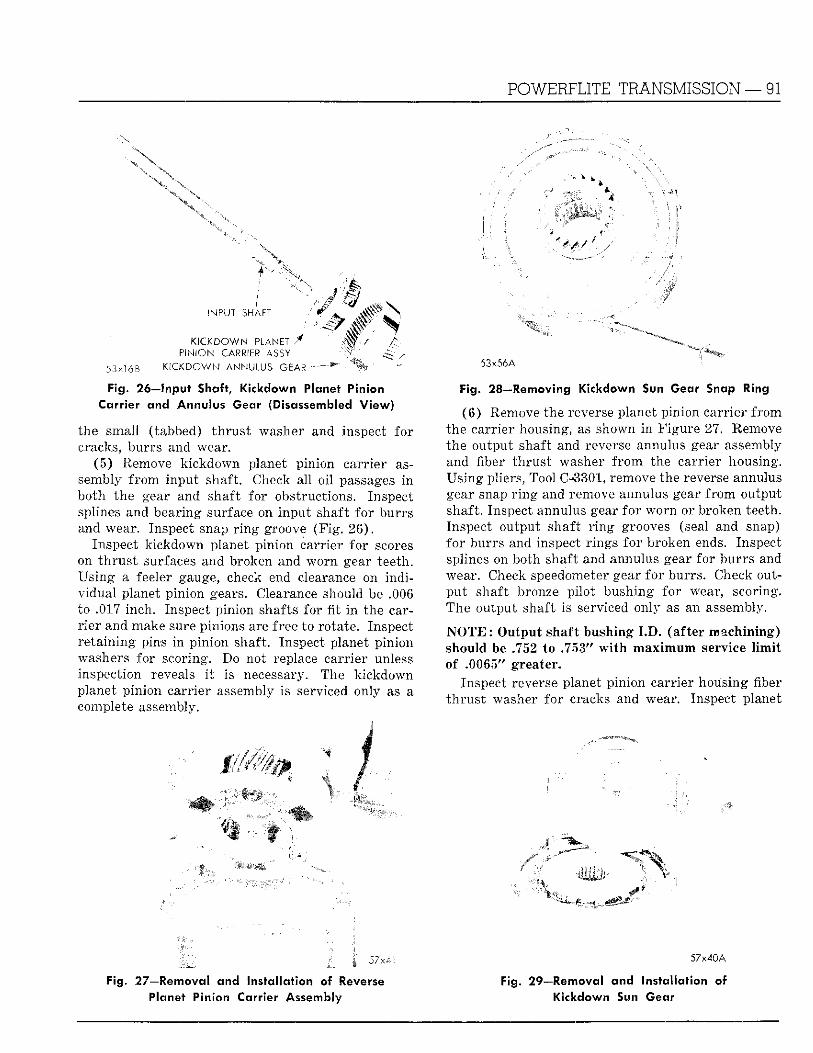
POWERFLITE TRANSMISSION — 91
4
INPUT SHAFT
KICKDOWN P L A N E T / PINION CARRIER ASSY
53x l6B K ICKDOWN ANNULUS GEAR
Fig. 26—Input Shaft, Kickdown Planet Pinion Carrier and Annulus Gear (Disassembled View)
the small (tabbed) th rus t washer and inspect for cracks, burrs and wear.
(5 ) Remove kickdown planet pinion carr ier assembly f r o m input shaft. Check all oi l passages in both the gear and shaft for obstructions. Inspect splines and bearing surface on input shaft for burrs and wear. Inspect snap r i n g groove (F ig . 26) .
Inspect k ickdown planet pinion carrier for scores on t h rus t surfaces and broken and worn gear teeth. Us ing a feeler gauge, check end clearance on ind i vidual planet pinion gears. Clearance should be .006 to .017 inch. Inspect pinion shafts for fit i n the carr ie r and make sure pinions are free to rotate. Inspect re ta in ing pins in p in ion shaft. Inspect planet pinion washers for scoring. Do not replace carr ier unless inspection reveals i t is necessary. The k ickdown planet pinion carrier assembly is serviced only as a complete assembly.
53x56A
Fig. 28—Removing Kickdown Sun Gear Snap Ring
(6 ) Remove the reverse planet pinion carr ier f rom the carrier housing, as shown in Figure 27. Remove the output shaft and reverse annulus gear assembly and fiber th rus t washer f r o m the carr ier housing. Us ing pliers, Tool C-3301, remove the reverse annulus gear snap r i n g and remove annulus gear f r o m output shaft. Inspect annulus gear fo r worn or broken teeth. Inspect output shaft r i n g grooves (seal and snap) fo r burrs and inspect r ings fo r broken ends. Inspect splines on both shaft and annulus gear for burrs and wear. Check speedometer gear fo r burrs . Check outpu t shaft bronze pi lot bushing for wear, scoring. The output shaft is serviced only as an assembly.
N O T E : Output shaft bushing I . D . (after machining) should be .752 to .753" w i t h m a x i m u m service l i m i t of .0065" greater.
Inspect reverse planet pinion carrier housing fiber t h ru s t washer for cracks and wear. Inspect planet
''mm
mm
Fig. 27—Removal and installation of Reverse Planet Pinion Carrier Assembly
57x40A
Fig. 29—Removal and Installation of Kickdown Sun Gear
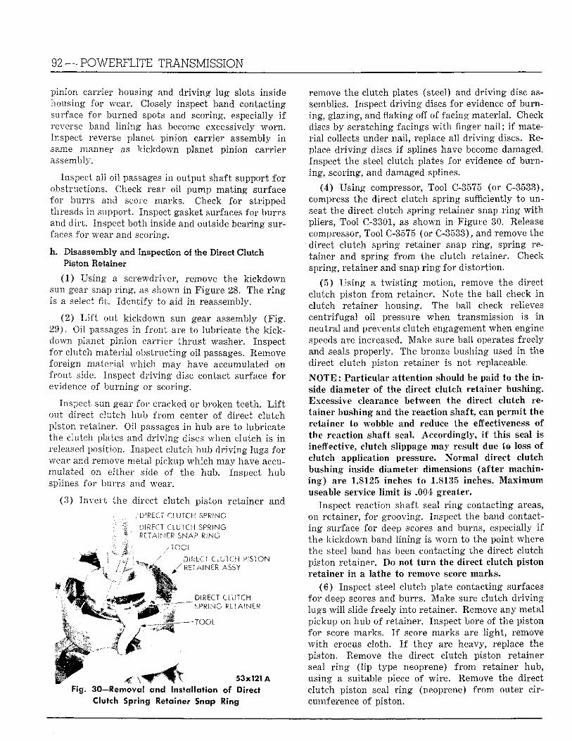
92 — POWERFLITE TRANSMISSION
pinion carrier housing and d r i v i n g lug slots inside housing for wear. Closely inspect band contacting surface for burned spots and scoring, especially i f reverse band l in ing has become excessively worn . Inspect reverse planet pinion carrier assembly i n same manner as kickdown planet pinion carr ier assembly.
Inspect all oil passages in output shaft support for obstructions. Check rear oil pump mat ing surface for burrs and score marks. Check for stripped threads i n support. Inspect gasket surfaces for burrs and d i r t . Inspect both inside and outside bearing surfaces for wear and scoring.
h. Disassembly and Inspection of the Direct Clutch Piston Retainer
(1) Using a screwdriver, remove the kickdown sun gear snap r ing , as shown i n Figure 28. The r i n g is a select fit. Iden t i fy to aid i n reassembly.
(2) L i f t out k ickdown sun gear assembly ( F i g . 29) . Oil passages i n f ron t are to lubricate the k ick -down planet pinion carr ier t h rus t washer. Inspect for clutch mater ia l obstruct ing oi l passages. Remove foreign mater ia l which may have accumulated on f ron t side. Inspect d r i v i n g disc contact surface fo r evidence of burn ing or scoring.
Inspect sun gear fo r cracked or broken teeth. L i f t out direct clutch hub f r o m center of direct c lutch piston retainer. Oil passages i n hub are to lubricate the clutch plates and d r iv ing discs when clutch is i n released position. Inspect clutch hub d r i v i n g lugs fo r wear and remove metal pickup which may have accumulated on either side of the hub. Inspect hub splines for burrs and wear.
(3) I nve r t the direct clutch piston retainer and
. DIRECT CLUTCH SPRING
' ^ . DIRECT CLUTCH SPRING : R L T A I N E? SNAP RING
DIRECT CLUTCH PISTON RETAINER A S S Y
DIRECT CLUTCH SPRING RETAINER
OOI.
53x121 A Fig. 30—Removed arid Installation of Direct
Clutch Spring Retainer Snap Ring
remove the clutch plates (steel) and dr iv ing disc assemblies. Inspect d r iv ing discs for evidence of burning, glazing, and flaking off of facing material . Check discs by scratching facings w i t h finger n a i l ; i f mater ia l collects under nai l , replace all d r iv ing discs. Replace d r i v i n g discs i f splines have become damaged. Inspect the steel clutch plates for evidence of burning, scoring, and damaged splines.
(4) Us ing compressor, Tool C-3575 (or C-3533), compress the direct clutch spring sufficiently to unseat the direct clutch spring retainer snap r i n g w i t h pliers, Tool C-3301, as shown i n Figure 30. Release compressor, Tool C-3575 (or C-3533), and remove the direct clutch spring retainer snap r ing , spring retainer and spring f r o m the clutch retainer. Check spring, retainer and snap r i n g for dis tor t ion.
(5) Using a t w i s t i n g motion, remove the direct clutch piston f rom retainer. Note the ball check i n clutch retainer housing. The ball check relieves centr i fugal oi l pressure when transmission is i n neutra l and prevents clutch engagement when engine speeds are increased. Make sure ball operates freely and seals properly. The bronze bushing used i n the direct clutch piston retainer is not replaceable.
N O T E : Particular attention should be paid to the inside diameter of the direct clutch retainer bushing. Excessive clearance between the direct clutch retainer bushing and the reaction shaft, can permit the retainer to wobble and reduce the effectiveness of the reaction shaft seal. Accordingly, if this seal is ineffective, clutch slippage may result due to loss of clutch application pressure. Normal direct clutch bushing inside diameter dimensions (after machining) are 1.8125 inches to 1.8135 inches. Maximum useable service limit is .004 greater.
Inspect reaction shaft seal r i n g contacting areas, on retainer, for grooving. Inspect the band contacting surface for deep scores and burns, especially i f the kickdown band l in ing is worn to the point where the steel band has been contacting the direct clutch piston retainer. Do not turn the direct clutch piston retainer in a lathe to remove score marks.
(6 ) Inspect steel clutch plate contacting surfaces for deep scores and burrs . Make sure clutch d r i v i n g lugs w i l l slide freely into retainer. Remove any metal pickup on hub of retainer. Inspect bore of the piston for score marks. I f score marks are l igh t , remove w i t h crocus cloth. I f they are heavy, replace the piston. Remove the direct clutch piston retainer seal r i n g ( l ip type neoprene) f r o m retainer hub, using a suitable piece of wi re . Remove the direct c lutch piston seal r i n g (neoprene) f r o m outer circumference of piston.
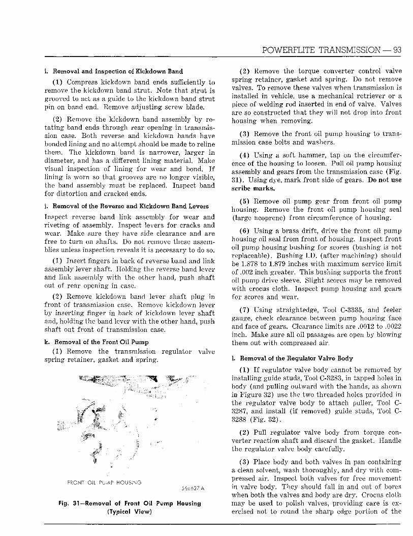
POWERFLITE TRANSMISSION — 93
i. Removal and Inspection of Kickdown Band
(1 ) Compress kickdown band ends sufficiently to remove the k ickdown band s t ru t . Note tha t s t ru t is grooved to act as a guide to the kickdown band s t ru t pin on band end. Remove adjust ing screw blade.
(2) Remove the kickdown band assembly by rot a t i n g band ends th rough rear opening i n transmission case. Bo th reverse and kickdown bands have bonded l i n ing and no at tempt should be made to reline them. The kickdown band is narrower, larger i n diameter, and has a different l i n i n g mater ia l . Make visual inspection of l i n ing for wear and bond. I f l i n ing is worn so tha t grooves are no longer visible, the band assembly must be replaced. Inspect band for d is tor t ion and cracked ends.
j . Removal of the Reverse and Kickdown Band Levers
Inspect reverse band l ink assembly fo r wear and r ive t i ng of assembly. Inspect levers fo r cracks and wear. Make sure they have side clearance and are free to t u r n on shafts. Do not remove these assemblies unless inspection reveals i t is necessary to do so.
(1) Insert fingers i n back of reverse band and l ink assembly lever shaft. Holding the reverse band lever and l i nk assembly w i t h the other hand, push shaft out of rear opening i n case.
(2 ) Remove kickdown band lever shaft p lug i n f ron t of transmission case. Remove kickdown lever by inser t ing finger i n back of k ickdown lever shaft and, holding the band lever w i t h the other hand, push shaft out f ron t of transmission case.
k. Removal of the Front Oil Pump (1) Remove the transmission regulator valve
spring retainer, gasket and "spring.
WmW mmW' 0mm?.
FRONT O i l PLMP HOUSING .56x627 A
Fig. 31—Removal of Front Oil Pump Housing (Typical V iew)
(2 ) Remove the torque converter control valve spring retainer, gasket and spring. Do not remove valves. To remove these valves when transmission is installed i n vehicle, use a mechanical retr iever or a piece of welding rod inserted i n end of valve. Valves are so constructed tha t they w i l l not drop into f ron t housing when removing.
(3) Remove the f ron t oi l pump housing to transmission case bolts and washers.
(4 ) Us ing a soft hammer, tap on the circumference of the housing to loosen. Pu l l oil pump housing assembly and gears f rom the transmission case (F ig . 31) . Using dye, mark f ron t side of gears. Do not use scribe marks.
(5) Remove oi l pump gear f r o m f ron t oil pump housing. Remove the f ron t oi l pump housing seal (large neoprene) f r o m circumference of housing.
(6) Us ing a brass d r i f t , dr ive the f ron t oil pump housing oil seal f r o m f ron t of housing. Inspect f ron t oil pump housing bushing for scores (bushing is not replaceable). Bushing I . D . (after machining) should be 1.878 to 1.879 inches w i t h m a x i m u m service l i m i t of .002 inch greater. This bushing supports the f ron t oil pump drive sleeve. Sl ight scores may be removed w i t h crocus cloth. Inspect pump housing and gears for scores and wear.
(7 ) Using straightedge, Tool C-3335, and feeler gauge, check clearance between pump housing face and face of gears. Clearance l imi t s are .0012 to .0022 inch. Make sure al l oi l passages are open by blowing them out w i t h compressed air.
L Removal of the Regulator Valve Body
(1 ) I f regulator valve body cannot be removed by ins ta l l ing guide studs, Tool C-3283, i n tapped holes i n body (and pul l ing outward w i t h the hands, as shown in Figure 32) use the two threaded holes provided i n the regulator valve body to attach puller, Tool C-3287, and insta l l ( i f removed) guide studs, Tool C-3288 (F ig . 32) .
(2) Pul l regulator valve body f rom torque converter reaction shaft and discard the gasket. Handle the regulator valve body carefully.
(3 ) Place body and both valves in pan containing a clean solvent, wash thoroughly, and d ry w i t h compressed air. Inspect both valves for free movement i n valve body. They should fa l l i n and out of bores when both the valves and body are dry. Crocus cloth may be used to polish valves, providing care is exercised not to round the sharp edge por t ion of the
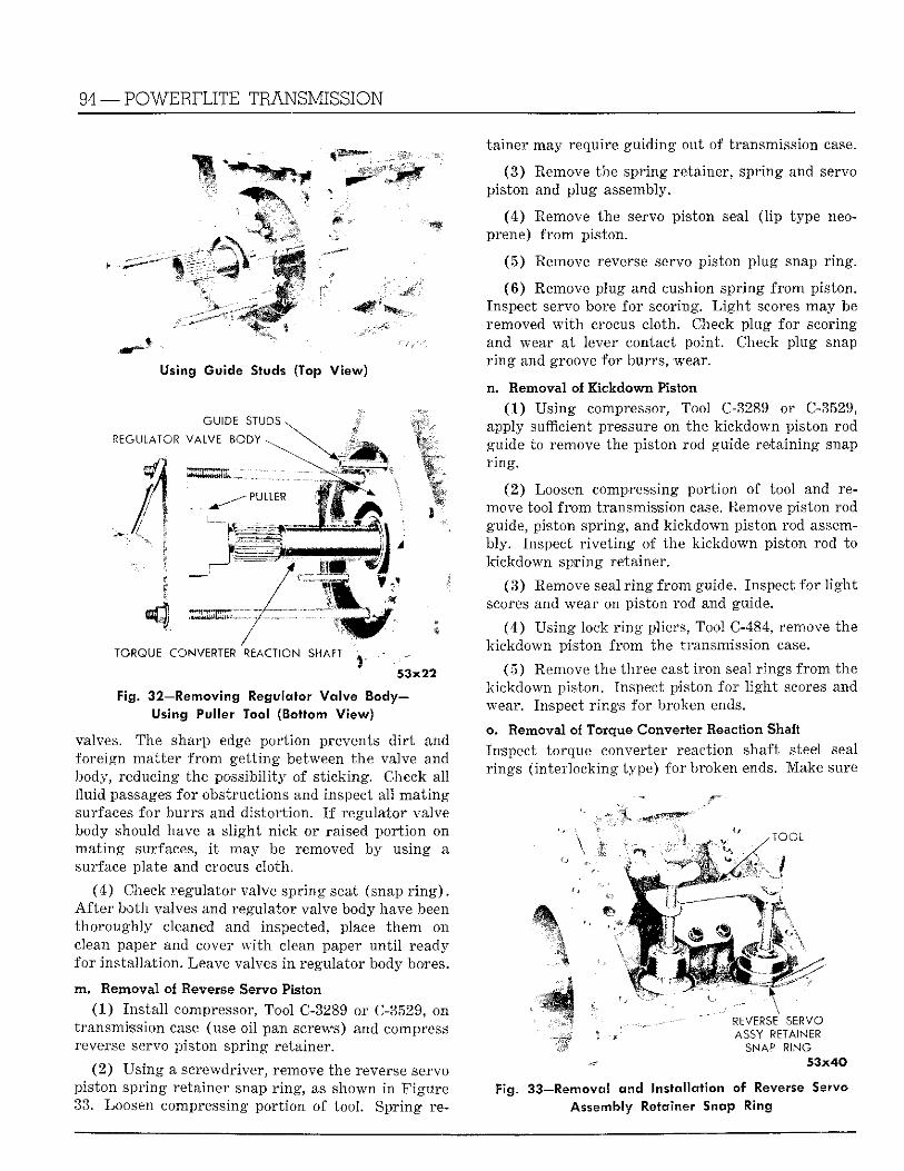
94 —POWERFLITE TRANSMISSION
mi6""'
Using Guide Studs (Top View)
TORQUE CONVERTER REACTION SHAFT
Fig. 32—Removing Regulator Valve Body-Using Puller Tool (Bottom View)
valves. The sharp edge por t ion prevents d i r t and foreign mat te r f r o m ge t t ing between the valve and body, reducing the possibil i ty of s t icking. Check all fluid passages for obstructions and inspect all ma t i ng surfaces for burrs and dis tor t ion. I f regulator valve body should have a s l ight nick or raised por t ion on ma t ing surfaces, i t may be removed by using a surface plate and crocus cloth.
(4 ) Check regulator valve spring seat (snap r i n g ) . A f t e r both valves and regulator valve body have been thoroughly cleaned and inspected, place them on clean paper and cover w i t h clean paper u n t i l ready for instal lat ion. Leave valves i n regulator body bores.
m. Removal of Reverse Servo Piston (1 ) Ins ta l l compressor, Tool C-3289 or C-3529, on
transmission case (use oil pan screws) and compress reverse servo piston spring retainer.
(2 ) Us ing a screwdriver, remove the reverse servo piston spr ing retainer snap r i n g , as shown i n F igure 33. Loosen compressing por t ion of tool. Spr ing re
tainer may require guiding out of transmission case.
(3) Remove the spring retainer, spring and servo piston and plug assembly.
(4) Remove the servo piston seal ( l ip type neoprene) f r o m piston.
(5) Remove reverse servo piston plug snap r ing .
(6 ) Remove plug and cushion spring f rom piston. Inspect servo bore for scoring. L i g h t scores may be removed w i t h crocus cloth. Check plug for scoring and wear at lever contact point. Check plug snap r i n g and groove for burrs, wear.
n. Removal of Kickdown Piston (1 ) Using compressor, Tool C-3289 or C-3529,
apply sufficient pressure on the kickdown piston rod guide to remove the piston rod guide re ta in ing snap r i ng .
(2 ) Loosen compressing por t ion of tool and remove tool f r o m transmission case. Remove piston rod guide, piston spring, and kickdown piston rod assembly. Inspect r ive t ing of the k ickdown piston rod to kickdown spring retainer.
(3 ) Remove seal r i n g f rom guide. Inspect for l i gh t scores and wear on piston rod and guide.
(4 ) Using lock r i n g pliers, Tool C-484, remove the kickdown piston f rom the transmission case.
(5) Remove the three cast i ron seal r ings f r o m the kickdown piston. Inspect piston for l i g h t scores and wear. Inspect r ings for broken ends.
o. Removal of Torque Converter Reaction Shaft Inspect torque converter reaction shaft steel seal r ings ( inter locking type) for broken ends. Make sure
R E V E R S E S E R V O
A S S Y RETAINER SNAP R I N G
53x40
Fig. 33—Removal and Installation of Reverse Servo Assembly Retainer Snap Ring
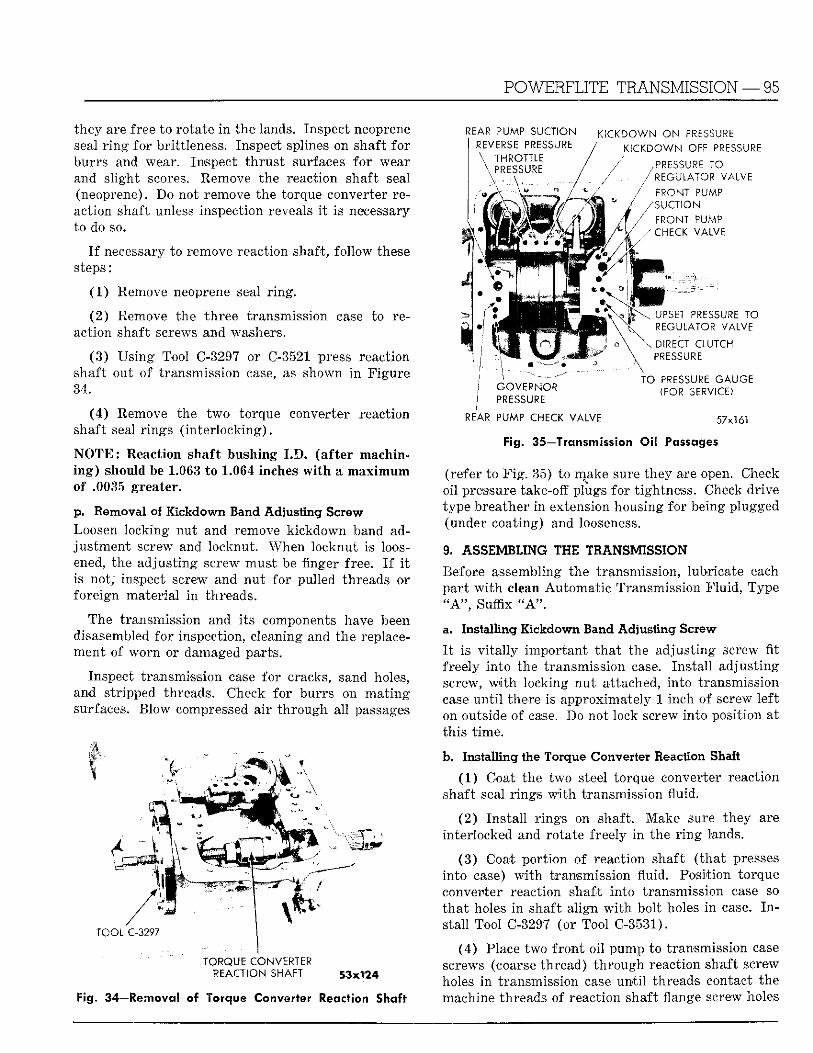
POWERFLITE TRANSMISSION — 95
they are free to rotate In the lands. Inspect neoprene seal r i n g for brittleness. Inspect splines on shaft for burrs and wear. Inspect t h ru s t surfaces fo r wear and s l ight scores. Remove the reaction shaft seal (neoprene). Do not remove the torque converter reaction shaft unless inspection reveals i t is necessary to do so.
I f necessary to remove reaction shaft, fol low these steps:
(1) Remove neoprene seal r i ng .
(2 ) Remove the three transmission case to reaction shaft screws and washers.
(3 ) Us ing Tool C-3297 or C-3521 press reaction shaft out of transmission case, as shown i n Figure 34.
(4 ) Remove the two torque converter reaction shaft seal r ings ( in te r lock ing) .
N O T E : Reaction shaft bushing I . D . (af ter machini n g ) should be 1.063 to 1.064 inches w i t h a max imum of .0035 greater.
p. Removal of Kickdown, Band Adjusting Screw Loosen locking nu t and remove k ickdown band adjus tment screw and locknut. When locknut is loosened, the adjus t ing screw must be finger free. I f i t is not, inspect screw and nu t for pulled threads or foreign mater ia l i n threads.
The transmission and i ts components have been disasembled fo r inspection, cleaning and the replacement o f worn or damaged parts.
Inspect transmission case for cracks, sand holes, and stripped threads. Check for burrs on ma t ing surfaces. Blow compressed a i r th rough al l passages
_,:y •.
/ TOOL C-3297
TORQUE CONVERTER REACT ION SHAFT
REAR PUMP SUCTION REVERSE PRESSURE
OTTLE \
\ PRESSURE
i \
K I C K D O W N O N PRESSURE ' / K I C K D O W N OFF PRESSURE
/ 7 PRESSURE TO / - / REGULATOR VALVE
/ FRONT PUMP , ' / S U C T I O N
• •' , ' / FRONT PUMP ' ' / / /CHECK VALVE
; G O V E R N O R I PRESSURE
REAR PUMP CHECK VALVE
\ UPSET PRESSURE TO REGULATOR VALVE
\ DIRECT CLUTCH PRESSURE
\ TO PRESSURE GAUGE
(FOR SERVICE)
57x161
Fig. 34—Removal o f Torque Converter Reaction Shaft
Fig. 35—Transmission Oil Passages
(refer to F i g . 35) to make sure they are open. Check oi l pressure take-off plugs for tightness. Check drive type breather i n extension housing for being plugged (under coating) and looseness.
9. ASSEMBLING THE TRANSMISSION
Before assembling the transmission, lubricate each par t w i t h clean Automat ic Transmission F lu id , Type " A " , Suffix " A " .
a. Installing Kickdown Band Adjusting Screw
I t is v i t a l l y impor tan t t ha t the adjust ing screw f i t freely in to the transmission case. Ins ta l l adjust ing screw, w i t h locking nu t attached, in to transmission case u n t i l there is approximately 1 inch of screw lef t on outside of case. Do not lock screw into posit ion at th is t ime.
b. Installing the Torque Converter Reaction Shaft
(1 ) Coat the two steel torque converter reaction shaft seal r ings w i t h transmission fluid.
(2 ) Ins ta l l r ings on shaft. Make sure they are interlocked and rotate freely i n the r i n g lands.
(3 ) Coat por t ion of reaction shaft ( tha t presses into case) w i t h transmission fluid. Posit ion torque converter reaction shaft in to transmission case so tha t holes i n shaft al ign w i t h bolt holes i n case. I n stall Tool C-3297 (or Tool C-3531).
(4) Place two f ron t o i l pump to transmission case screws (coarse thread) t h r o u g h reaction shaft screw holes i n transmission case u n t i l threads contact the machine threads of reaction shaft flange screw holes
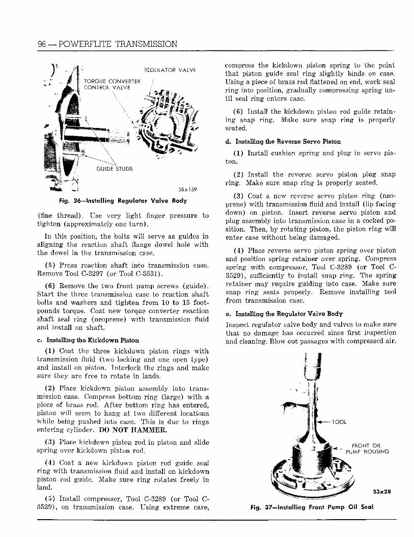
96 — POWERFLITE TRANSMISSION
I REGULATOR VALVE ! / ! TORQUE CONVERTER ; CONTROL V A L V E
GUIDE STUDS
J 56x159
Fig. 36—Installing Regulator Waive Body
(fine th read) . Use very l i g h t finger pressure to t igh ten (approximately one t u r n ) .
I n this position, the bolts w i l l serve as guides i n a l igning the reaction shaft flange dowel hole w i t h the dowel in the transmission case.
(5 ) Press reaction shaft in to transmission case. Eemove Tool C-3297 (or Tool C-3531).
(6 ) Remove the two f ron t pump screws (guide) . S tar t the three transmission case to reaction shaft bolts and washers and t i gh t en f r o m 10 to 15 footpounds torque. Coat new torque converter reaction shaft seal r i n g (neoprene) w i t h transmission f luid and instal l on shaft.
c. Installing the Kickdown Piston
(1 ) Coat the three k ickdown piston r ings w i t h transmission fluid ( two locking and one open type) and instal l on piston. In ter lock the r ings and make sure they are free to rota te i n lands.
(2 ) Place k ickdown piston assembly in to t ransmission case. Compress bo t tom r i n g (large) w i t h a piece of brass rod. A f t e r bo t tom r i n g has entered, piston w i l l seem to hang at two different locations whi le being pushed in to case. This is due to r ings entering cylinder. DO N O T H A M M E R .
(3 ) Place k ickdown piston rod i n piston and slide spr ing over k ickdown piston rod.
(4 ) Coat a new k ickdown piston rod guide seal r i n g w i t h transmission fluid and insta l l on k ickdown piston rod guide. Make sure r i n g rotates freely i n land.
( 5 ) Ins ta l l compressor, Tool C-3289 (or Tool C-3529), on transmission case. Us ing extreme care,
compress the kickdown piston spring to the point tha t piston guide seal r i n g s l igh t ly binds on case. Using a piece of brass rod flattened on end, work seal r i n g into position, gradually compressing spring unt i l seal r i n g enters case.
(6 ) Ins ta l l the kickdown piston rod guide retaining snap r ing . Make sure snap r i n g is properly seated.
d. Installing the Reverse Servo Piston
(1) Ins ta l l cushion spr ing and plug i n servo piston.
(2 ) Insta l l the reverse servo piston plug snap r i n g . Make sure snap r i n g is properly seated.
(3 ) Coat a new reverse servo piston r i n g (neoprene) w i t h transmission fluid and instal l ( l ip facing down) on piston. Insert reverse servo piston and plug assembly into transmission case i n a cocked posi t ion. Then, by ro t a t ing piston, the piston r i n g w i l l enter case wi thou t being damaged.
(4 ) Place reverse servo piston spring over piston and position spring retainer over spring. Compress spr ing w i t h compressor, Tool C-3289 (or Tool C-3529), sufficiently to instal l snap r i n g . The spr ing retainer may require gu id ing in to case. Make sure snap r i n g seats properly. Remove ins ta l l ing tool f r o m transmission case.
e. Installing the Regulator Valve Body
Inspect regulator valve body and valves to make sure t ha t no damage has occurred since first inspection and cleaning. Blow out passages w i t h compressed air .
I ^ — T O O L
IF Wfcfef' FRONT OIL
' ' PUMP HOUS ING
53x28
Fig. 37—Installing Front Pump Oil Seal
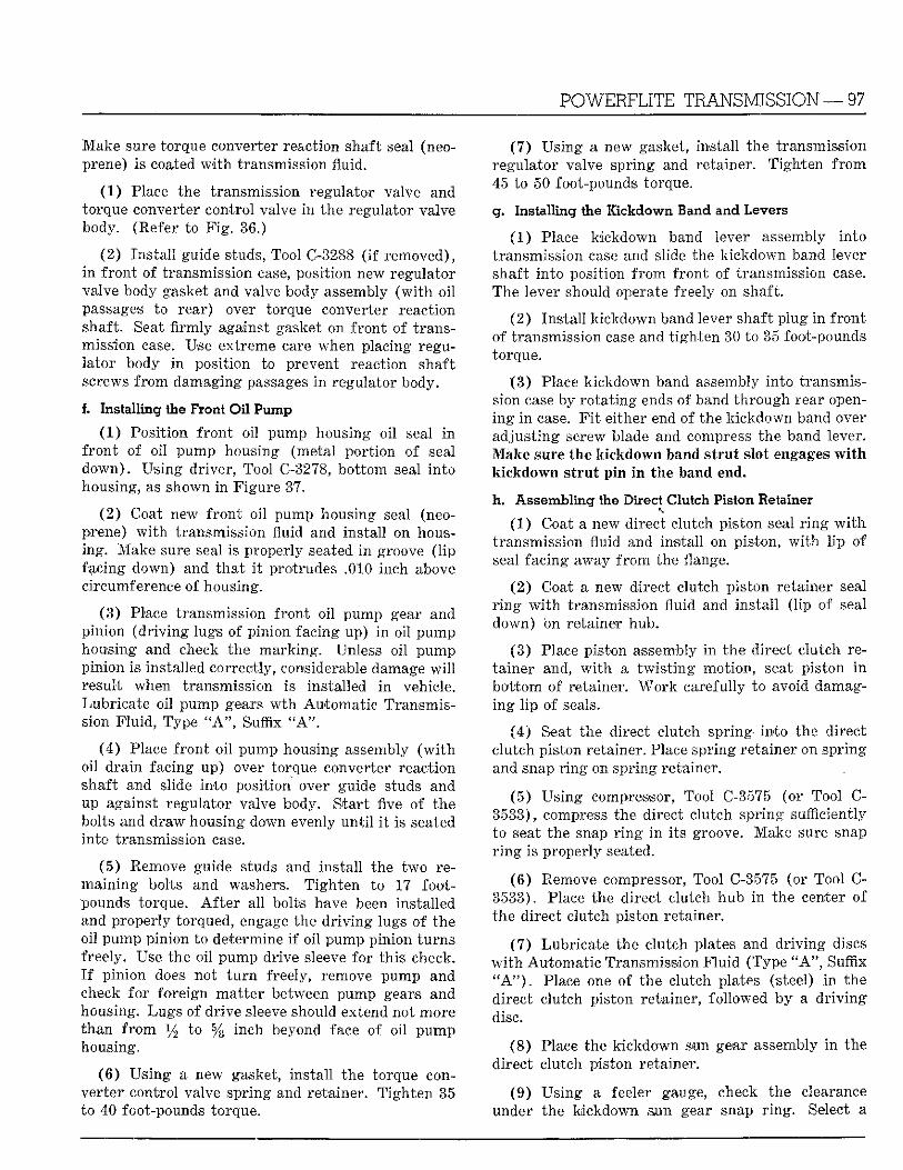
POWERFLITE TRANSMISSION — 97
Make sure torque converter reaction shaft seal (neoprene) is coated w i t h transmission fluid.
( 1 ) Place the transmission regulator valve and torque converter control valve i n the regulator valve body. (Refer to F i g . 36.)
(2 ) Ins ta l l guide studs, Tool C-3288 ( i f removed), i n f ron t of transmission case, position new regulator valve body gasket and valve body assembly ( w i t h o i l passages to rear) over torque converter reaction shaft. -Seat firmly against gasket on f ron t of transmission case. Use extreme care when placing regula tor body i n posit ion to prevent reaction shaft screws f r o m damaging passages i n regulator body.
I . Installing the Front Oil Pump
(1) Posit ion f ron t oi l pump housing oi l seal i n f ron t of oil pump housing (metal por t ion of seal down) . Us ing driver , Tool C-3278, bo t tom seal in to housing, as shown i n Figure 37,
( 2 ) Coat new f ron t oi l pump housing seal (neoprene) w i t h transmission fluid and ins ta l l on housing. Make sure seal is properly seated i n groove ( l ip facing down) and tha t i t protrudes .010 inch above circumference of housing.
(3 ) Place transmission f ron t oi l pump gear and pinion ( d r i v i n g lugs of pinion facing up) i n ' o i l pump housing and' check the mark ing . Unless oi l pump pinion is installed correctly, considerable damage w i l l result when transmission is installed i n vehicle. Lubricate oi l pump gears w t h Automat ic Transmission F lu id , Type " A " , Suffix " A " .
(4 ) Place f ron t o i l pump housing assembly ( w i t h oil d ra in facing up) over torque converter reaction shaft and slide in to position over guide studs and up against regulator valve body. S tar t five of the bolts and draw housing down evenly u n t i l i t is seated into transmission case.
(5 ) Remove guide studs and ins ta l l the two remain ing bolts and washers. T igh ten to 17 footpounds torque. A f t e r al l bolts have been installed and properly torqued, engage the d r i v i n g lugs o f the oi l pump pinion to determine i f oi l pump pinion tu rns freely. Use the oi l pump drive sleeve for th is check. I f p in ion does not t u r n freely, remove pump and check fo r foreign ma t t e r between pump gears and housing. Lugs of dr ive sleeve should extend not more than f r o m y2 to % inch beyond face of oi l pump housing.
( 8 ) Us ing a new gasket, ins ta l l the torque converter control valve spr ing and retainer. T igh ten 35 to 40 foot-pounds torque.
(7 ) Us ing a new gasket, ins ta l l the transmission regulator valve spr ing and retainer. T igh ten f r o m 45 to 50 foot-pounds torque.
g. Installing the Kickdown Band and Levers
(1 ) Place k ickdown band lever assembly in to transmission case and slide the k ickdown band lever shaft in to position f r o m f ron t of transmission case. The lever should operate freely on shaft.
(2 ) Ins ta l l k ickdown band lever shaft p lug i n f ron t of t ransmission case and t igh ten 30 to 35 foot-pounds torque.
( 3 ) Place k ickdown band assembly in to transmission case by ro t a t i ng ends of band th rough rear openi n g i n case. F i t either end of the k ickdown band over adjus t ing screw blade and compress the band lever. Make sure the kickdown band strut slot engages with kickdown strut pin i n the band end.
h . Assembling the Direct Clutch Piston Retainer
(1 ) Coat a new direct clutch pis ton seal r i n g w i t h transmission fluid and instal l on piston, w i t h l i p of seal facing away f r o m the flange.
(2 ) Coat a new direct clutch piston retainer seal r i n g w i t h transmission fluid and ins ta l l ( l ip of seal down) on retainer hub.
(3 ) Place piston assembly i n the direct c lutch retainer and, w i t h a t w i s t i n g motion, seat piston i n bo t tom of retainer. W o r k carefully to avoid damagi n g l i p of seals.
(4) Seat the direct clutch spring- in to the direct c lutch piston retainer. Place spr ing retainer on spr ing and snap r i n g on spr ing retainer.
(5 ) Us ing compressor, Tool C-3575 (or Tool C-3533), compress the direct clutch spr ing sufficiently to seat the snap r i n g i n i ts groove. Make sure snap r i n g is properly seated.
(6 ) Remove compressor, Tool C-3575 (or Tool C-3533). Place the direct clutch hub i n the center of the direct clutch piston retainer.
(7 ) Lubr icate the clutch plates and d r i v i n g discs w i t h Automat ic Transmission F l u i d (Type " A " , Suffix " A " ) . Place one of the clutch plates (steel) i n the direct clutch piston retainer, followed by a d r i v i n g disc.
( 8 ) Place the k ickdown sun gear assembly i n the direct clutch piston retainer.
(9 ) Us ing a feeler gauge, check the clearance under the kickdown mn gear snap r i n g . Select a
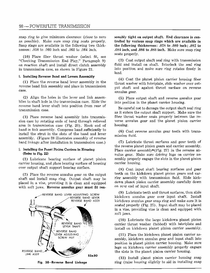
98 —POWERFLITE TRANSMISSION
snap r i n g to give m i n i m u m clearance (close to zero as possible). Make sure snap r i n g seats properly. Snap r ings are available i n the fo l lowing two th icknesses: .058 to .060 inch and .062 to .064 inch.
(10) Place fiber t h rus t washer (select fit, see "Checking Transmission End Play," Paragraph 9) on reaction shaft and instal l direct c lutch assembly i n transmission case, as shown i n F igure 2 1 .
i. Installing Reverse Band and Levers Assembly
(1) Place the reverse band lever assembly i n the reverse band l i n k assembly and place i n transmission case.
(2) A l i g n the holes i n the lever and l i nk assemblies to shaft hole i n the transmission case. Slide the reverse band lever shaft in to position f r o m rear of transmission case.
(3 ) Place reverse band assembly in to t ransmission case by r o t a t i n g ends of band t h r o u g h relieved area in transmission case (F ig . 20) . Hook end o f band i n l i n k assembly. Compress band sufficiently to ins ta l l the s t r u t i n the slots of the band and lever assembly. (F igu re 38 i l lustrates assembly of reverse band linkage after instal la t ion i n transmission case.)
j . Installing the Panet Pinion Carriers in Housing (Refer to Fig. 22)
(1) Lubr ica te bearing surface of planet pinion carr ier housing, and place bearing surface of housing over output shaft support bearing surface.
(2 ) Place the reverse annulus gear on the output shaft and ins ta l l snap r i n g . Output shaft may be placed i n a vise, p rov id ing i t is clean and equipped w i t h soft jaws. Reverse annulus gear must fit rea-
- REVERSE BAND LEVER ADJUSTING SCREW -REVERSE BAND LEVER
REVERSE BAND ASSY
y
REVERSE BAND LEVER SHAFT •
REVERSE BAND LEVER ADJUSTING
SCREW NUT
i " 17)' REVERSE BANG,
LINK ASSY 53x50
Fig. 38—Reverse Band Linkage
sonably tight on output shaft. E n d clearance is controlled by various snap rings which are available in the following thicknesses: .078 to .080 inch ; .082 to .084 inch, and .086 to .088 inch. Make sure snap r i n g seats properly.
(3 ) Coat output shaft seal r i n g w i t h transmission fluid and instal l on shaft. Inter lock the seal r i n g into posit ion and make sure r i n g rotates freely i n land.
(4 ) Coat the planet pinion carr ier housing fiber th rus t washer w i t h lubriplate, slide washer over outpu t shaft and against t h rus t surface on reverse annulus gear.
(5 ) Place output shaft and reverse annulus gear in to position i n the planet carr ier housing.
Be careful not to damage the output shaft seal r i n g as i t enters the output shaft support. Make sure the fiber t h rus t washer seats properly between the reverse annulus gear and the planet pinion carr ier housing.
(6 ) Coat reverse annulus gear teeth w i t h transmission fluid.
(7 ) Lubricate th rus t surfaces and gear teeth of the reverse planet pinion gears and carr ier assembly. Place carrier assembly*(Fig. 27) i n the reverse annulus gear. Make sure d r i v i n g lugs on carr ier assembly properly engage the slots i n the planet pinion carr ier housing.
( 8 ) Coat input shaft bearing surfaces and gear teeth on the kickdown planet pinion gears and carrier assembly w i t h transmission fluid. Slide k ick-down planet pinion carrier assembly carefully down on rear end of input shaft.
(9 ) Lubr icate teeth and th rus t surfaces, then slide kickdown annulus gear over input shaft. Ins ta l l k ickdown annulus gear snap r i n g and make sure i t is seated properly (F ig . 25) . I npu t shaft may be placed i n a vise, p rovid ing vise is clean and equipped w i t h soft jaws.
(10) Lubr icate the large k ickdown planet p in ion carr ier t h rus t washer (tabbed) w i t h lubriplate and ins ta l l on kickdown planet pinion carrier assembly.
(11) Place the k ickdown planet pinion carr ier assembly, k ickdown annulus gear and input shaft into position i n planet p inion carrier housing. Make sure lugs on kickdown carrier assembly properly engage the slots i n the planet pinion carr ier housing.
(12) Ins ta l l planet pinion carr ier housing snap r i n g (raise housing s l ight ly to aid i n ins ta l l ing snap
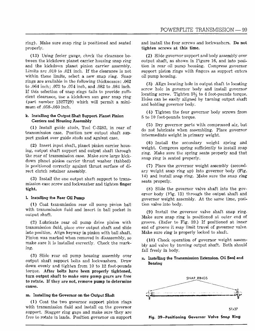
POWERFLITE TRANSMISSION — 99
r i n g ) . Make sure snap r i n g is positioned and seated properly.
(13) Us ing feeler gauge, check the clearance between the k ickdown planet carr ier housing snap r i n g and the kickdown planet pinion carr ier assembly. L i m i t s are .010 to .021 inch. I f the clearance is not w i t h i n these l imi t s , select a new snap r i n g . Snap-r ings are available i n the fo l lowing thicknesses: .062 to .064 i nch ; .072 to .074 inch, and .082 to .084 inch. I f t h i s selection of snap rings fails to provide sufficient clearance, use a k ickdown sun gear snap r i n g (par t number 1327729) which w i l l pe rmi t a m i n i m u m of .058-.060 inch.
k. Installing the Output Shaft Support, Planet Pinion Carriers and Housing Assembly
(1 ) Ins ta l l guide studs, Tool C-3283, i n rear of t ransmission case. Position new output shaft suppor t gasket over guide studs and against case.
( 2 ) Inser t input shaft, planet pinion carrier housing, output shaft support and output shaft t h rough the rear of transmission case. Make sure large k ick-down planet pinion carrier t h rus t washer (tabbed) is positioned correctly against t h r u s t surface of d i rect clutch retainer assembly.
( 3 ) Ins ta l l the one output shaft support to transmission case screw and lockwasher and t igh ten finger t i g h t .
1. Installing the Rear Oil Pump
(1 ) Coat transmission rear oi l pump pinion bal l w i t h transmission fluid and insert i n bal l pocket i n output shaft.
(2 ) Lubricate rear o i l pump drive pinion w i t h transmission fluid, place over output shaft and slide in to position. A l i g n keyway i n p in ion w i t h ball shaft. P in ion was marked when removed i n disassembly, so make sure i t is installed correctly. Check the marking .
( 3 ) Slide rear o i l pump housing assembly over output shaft support bolts and lockwashers. Draw down evenly and t i gh ten f r o m 10 to 12 foot-pounds torque. After bolts have been properly tightened, turn output shaft to make sure pump gears are free to rotate. I f they are not, remove pump to determine cause.
m. Installing the Governor on the Output Shaft
(1 ) Coat the two governor support piston r ings w i t h transmission fluid and ins ta l l on the governor support. Stagger r i n g gaps and make sure they are free to rotate i n lands. Posit ion governor on support
and insta l l the four screws and lockwashers. Do not tighten screws at this time.
(2 ) Slide governor support and body assembly over output shaft, as shown i n F igu re 16, and in to posit i o n i n rear oil pump housing. Compress governor support piston r ings w i t h fingers as support enters oi l pump housing.
(3 ) A l i g n locat ing hole i n output shaft to locating screw hole i n governor body and instal l governor locating screw. T igh ten 3l/2 to 4 foot-pounds torque. Holes can be easily aligned by t u r n i n g output shaft and holding governor body.
(4 ) T igh ten the four governor body screws f r o m 5 to 10 foot-pounds torque.
( 5 ) D r y governor parts w i t h compressed air , but do not lubricate when assembling. Place governor intermediate weigh t i n p r i m a r y weight .
( 6 ) Ins ta l l the secondary weight spr ing and weight . Compress spr ing sufficiently to ins ta l l snap r i n g . Make sure the spring seats properly and tha t snap r i n g is seated properly.
(7) Place the governor weigh t assembly (seconda ry weight snap r i n g up) in to governor body (F ig . 14) and instal l snap r i n g . Make sure the snap r i n g seats properly.
(8 ) Slide the governor valve shaft in to the governor body (F ig . 13) t h rough the output shaft and governor weight assembly. A t the same t ime, posit i o n valve in to body.
(9 ) Ins ta l l the governor valve shaft snap r i n g . Make sure snap r i n g is positioned at outer end of groove. (Refer to F i g . 39.) I f positioned at inner end of groove i t may l i m i t t r ave l of governor valve. Make sure r i n g is properly locked to shaft.
(10) Check operation of governor weight assembly and valve by t u r n i n g output shaft. B o t h should f a l l freely i n body.
n. Installing the Transmission Extension, Oil Seal and Bearing
SNAP RINGS
57x37
Fig. 39—Positioning Governor Valve Snap Ring
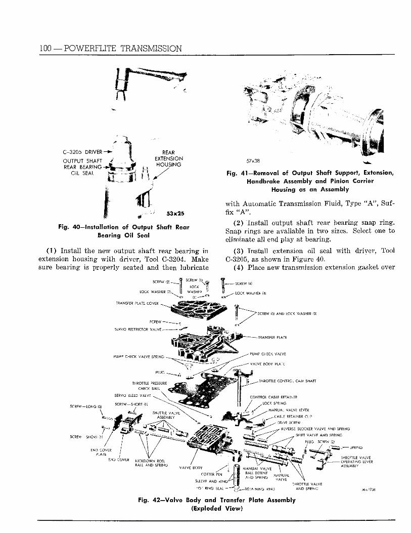
100 —POWERFLITE TRANSMISSION
i § If
C-3205 DRIVER- : -
OUTPUT SHAFT REAR BEARING -<>•
OIL SEAL t i
REAR EXTENSION HOUSING
57x38
Fig. 41—Removal of Output Shaft Support, Extension, Handbrake Assembly and Pinion Carrier
Housing as an Assembly
t -• 53x25
Fig. 40—Installation of Output Shaft Rear Bearing Oil Seal
(1 ) Ins ta l l the new output shaft rear bearing i n extension housing w i t h dr iver , Tool C-3204. Make sure bearing is properly seated and then lubricate
w i t h Automat ic Transmission F lu id , Type " A " , Suffix "A".
(2 ) I n s t a l l output shaft rear bearing snap r i n g . Snap r ings are available i n two sizes. Select one to eliminate al l end play at bearing.
(3 ) Ins ta l l extension oil seal w i t h driver , Tool O-3205, as shown i n F igure 40.
(4) Place new transmission extension gasket over
SCREW (25 •
LOCK WASHER (2)s^
TRANSFER PLATE COVER
SCREW ~
SERVO RESTRICTOR VALVE -
LOC.C
W A S H LP
0)-—*"
S C P P A ' (4)
L O " 1 W A S H E R (4)
SCREW (3) AND LOCK WASHER (3)
-TRANSFER PLATE
PUMP CHECK VALVE SPRING -
THROTTLE PRESSURE C H E C K B A L L
S C R E W — L O N G !3)
\
SCREW—-SHORT 1
END COVER PLATE
SERVO BLEED VALVE .
SCREW-SHORT (1)
/ it mtSm
S H U T T L E V A i V F ASSEMBL*'
END COVER K I C K D O W N ROD, BALL AND SPRING
/m
VALVE BODY
COTTER P I N / '
/ \
^ PUMP CHECK VALVE
V A L V E BODY PLATE
l i i J T H R O T T L E CONTROL CAM S H A F T
CONTROL CABLE RETAINER
, L O C K S P R I N G
M A N U A L VALVE LEVER
+ CABLE RETAINER -CLIP
- DRIVE SCREW >
• REVERSE BLOCKER VALVE AND SPRING
, SHIFT VALVE A N D SPRING
PLUG SCREW (2)
^ . ^ - JJ i ^ l f e ^J^f^^jK^m ' t y THROTTLE VALVE
"^Ttrf^ • * ':* —OPERAT ING LEVER T " \ \ A r j E M B L Y
M A N U A L V A L V E \ x x
SLEEVE AND R N O
" O " RING SEAL
l. w A ? ' U A L \ \
^EiAfNSNG PING I H . ' O n - L f VAiV=
AMD SPP'NG
Fig. 42—Valve Body and Transfer Plate Assembly (Exploded View)
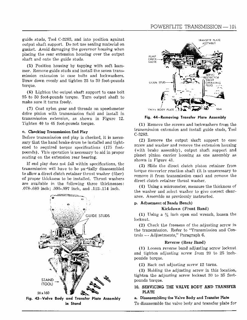
POWERFLITE TRANSMISSION—101
guide studs, Tool C-3283, and in to posit ion against output shaft support. Do not use sealing mater ia l on gasket. A v o i d damaging the governor housing when placing the rear extension housing over the output shaft and onto the guide studs.
(5 ) Posit ion housing by tapping w i t h soft hammer. Remove guide studs and ins ta l l the seven transmission extension to case bolts and lockwashers. D r a w down evenly and t i gh ten 25 to 30 foot-pounds torque.
(6 ) L i g h t e n the output shaft support to ease bolt 25 to 30 foot-pounds torque. T u r n output shaft to make sure i t tu rns freely.
( 7 ) Coat nylon gear and threads on speedometer dr ive pinion w i t h transmission f luid and ins ta l l i n transmission extension, as shown i n F igure 12. T igh ten 40 to, 45 foot-pounds torque.
o. Checking Transmission End Play Before transmission end play is checked, i t is necessary tha t the hand brake d r u m be installed and t i g h t ened to required torque specifications (175 footpounds) . This operation is necessary to aid i n proper seating on the extension rear bearing.
I f end play does not fa l l w i t h i n specifications, the transmission will have to be partially disassembled to allow a direct clutch retainer t h r u s t washer (fiber) o f proper thickness to be installed. Thrus t washers are available i n the fo l lowing three thicknesses: .078-.080 i nch ; .095-.097 inch, and .112-.114 inch.
TRANSFER PLATE ASSCAABLY
GUIDE STUDS
• • • I
STAND _ ( T O O ; )
56x160 Fig. 43—Valve . ' <zns
2H Si a I i d
P U M P CHECK VALVE ^
G U I D E STUD
' SERVO -RESTR1CTOR
VALVE OPERATING PLUG • •
1 VALVE BODY PLATE
rie Assembly
Pig. 44—Removing Transfer Plate Assembly
(1 ) Remove the screws and lockwashers f r o m the transmission extension and ins ta l l guide studs, Tool C-3283.
(2 ) Remove the output shaft support to case screw and washer and remove the extension housing ( w i t h brake assembly), output shaft support and planet pinion carr ier housing as one assembly as shown i n F igure 41 .
(3 ) Slide the direct clutch piston retainer f r o m torque converter reaction shaft ( i t is unnecessary to remove i t f r o m transmission case) and remove the direct clutch retainer th rus t washer.
(4 ) Us ing a micrometer, measure the thickness of the washer and select washer to give correct clearance. Assemble as previously instructed.
p. Adjustment of Bands (Bench) Kickdown ( F r o n t Band)
(1 ) Using a % inch open end wrench, loosen the locknut .
(2 ) Check the freeness of the adjust ing screw i n the transmission. Refer to "Transmission and Cont rols — Adjus tments ," Paragraph 6.
Reverse (Rear Band) (1 ) Loosen reverse band adjust ing screw locknut
and t igh ten adjus t ing screw f r o m 20 to 25 inch-pounds torque.
( 2 ) Back out adjus t ing screw 12 turns . (3 ) Hold ing the adjust ing screw i n th is location,
t i gh t en the adjust ing screw locknut 30 to 35 footpounds torque.
10. SERVICING THE VALVE BODY A N D TRANSFER PLATE
a. Disassembling the Valve Body and Transfer Plate To disassemble the valve body and transfer plate fo r
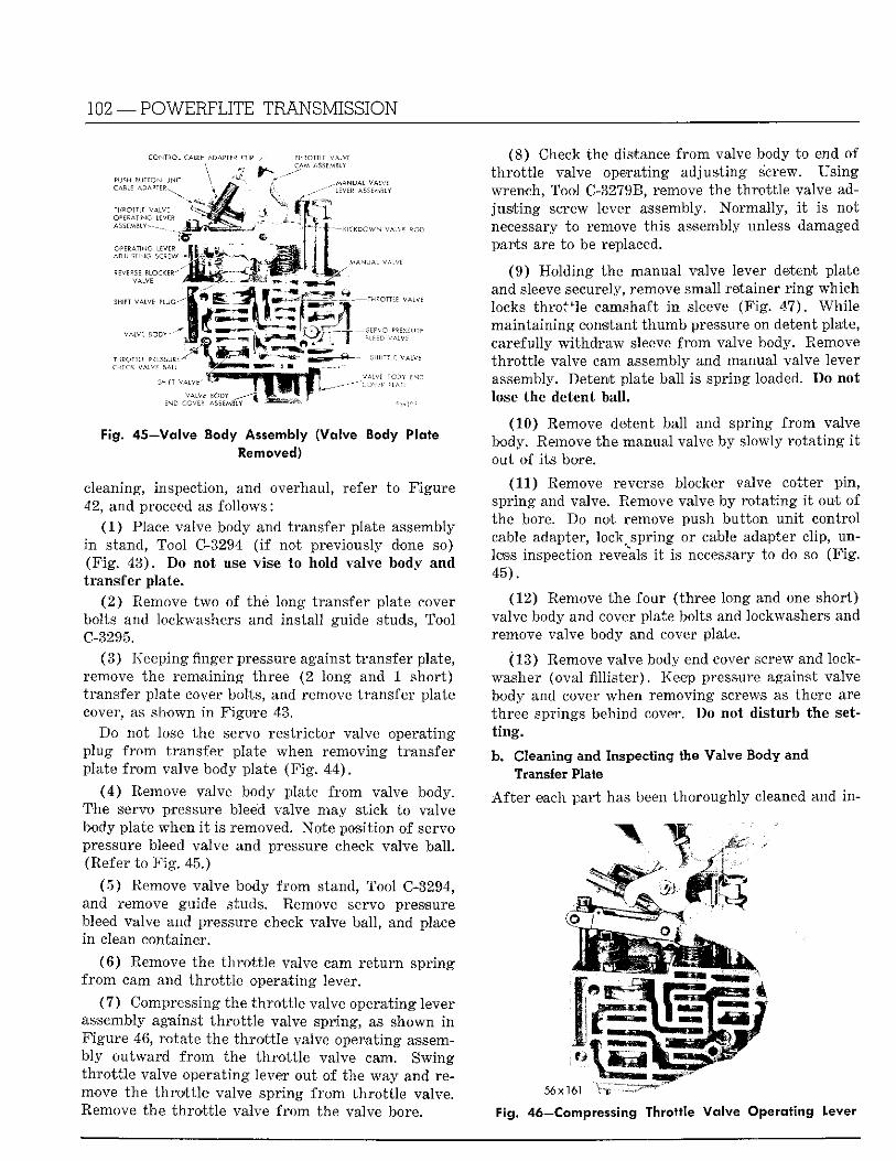
102 —POWERFLITE TRANSMISSION
CONTROL CABLE ADAPTER CLIP / THROTTLE VALVE
Fig. 45—Valve Body Assembly (Volve Body Plate Removed)
cleaning, inspection, and overhaul, refer to F igure 42, and proceed as fo l lows:
(1 ) Place valve body and transfer plate assembly i n stand, Tool C-3294 ( i f not previously done so) (F ig . 43) . Do not use vise to hold valve body and transfer plate.
(2 ) Remove two of the long transfer plate cover bolts and lockwashers and insta l l guide studs, Tool C-3295.
(3 ) Keeping finger pressure against t ransfer plate, remove the remaining three (2 long and 1 short ) t ransfer plate cover bolts, and remove t ransfer plate cover, as shown i n Figure 43.
Do not lose the servo res t r ic tor valve operating plug f r o m transfer plate when removing t ransfer plate f r o m valve body plate (F ig . 44) .
(4 ) Remove valve body plate f r o m valve body. The servo pressure bleed valve may st ick to valve body plate when i t is removed. Note posit ion of servo pressure bleed valve and pressure check valve bal l . (Refer to F i g . 45.)
( 5 ) Remove valve body f r o m stand, Tool C-3294, and remove guide studs. Remove servo pressure bleed valve and pressure check valve ball , and place i n clean container.
( 6 ) Remove the t h r o t t l e valve cam r e t u r n spr ing f r o m cam and t h r o t t l e operat ing lever.
( 7 ) Compressing the t h ro t t l e valve operating lever assembly against t h r o t t l e valve spring, as shown i n F igure 46, rotate the t h r o t t l e valve operating assembly ou tward f r o m the t h ro t t l e valve cam. Swing t h r o t t l e valve operat ing lever out of the way and remove the t h r o t t l e valve spr ing f r o m t h r o t t l e valve. Remove the t h r o t t l e valve f r o m the valve bore.
(8) Check the distance f r o m valve body to end of th ro t t l e valve operating adjust ing screw. Using wrench, Tool C-3279B, remove the th ro t t l e valve adj u s t i n g screw lever assembly. Normal ly , i t is not necessary to remove this assembly unless damaged parts are to be replaced.
(9 ) Hold ing the manual valve lever detent plate and sleeve securely, remove small retainer r i n g which locks th ro t t l e camshaft i n sleeve (F ig . 47) . Whi le main ta in ing constant thumb pressure on detent plate, carefully w i t h d r a w sleeve f r o m valve body. Remove th ro t t l e valve cam assembly and manual valve lever assembly. Detent plate ball is spring loaded. Do not lose the detent ball.
(10) Remove detent ball and spring f r o m valve body. Remove the manual valve by slowly ro t a t ing i t out of i ts bore.
(11) Remove reverse blocker valve cotter p in , spring and valve. Remove valve by ro ta t ing i t out of the bore. Do not remove push bu t ton un i t control cable adapter, lock^ spring or cable adapter clip, unless inspection reveals i t is necessary to do so (F ig . 45) .
(12) Remove the four (three long and one short) valve body and cover plate bolts and lockwashers and remove valve body and cover plate.
(13) Remove valve body end cover screw and lockwasher (oval f i l l i s t e r ) . Keep pressure against valve body and cover when removing screws as there are three springs behind cover. Do not disturb the setting.
b. Cleaning and Inspecting the Valve Body and Transfer Plate
A f t e r each par t has been thoroughly cleaned and i n -
56x161
Fig. 46—Compressing Throttle Va lve Operating Lever
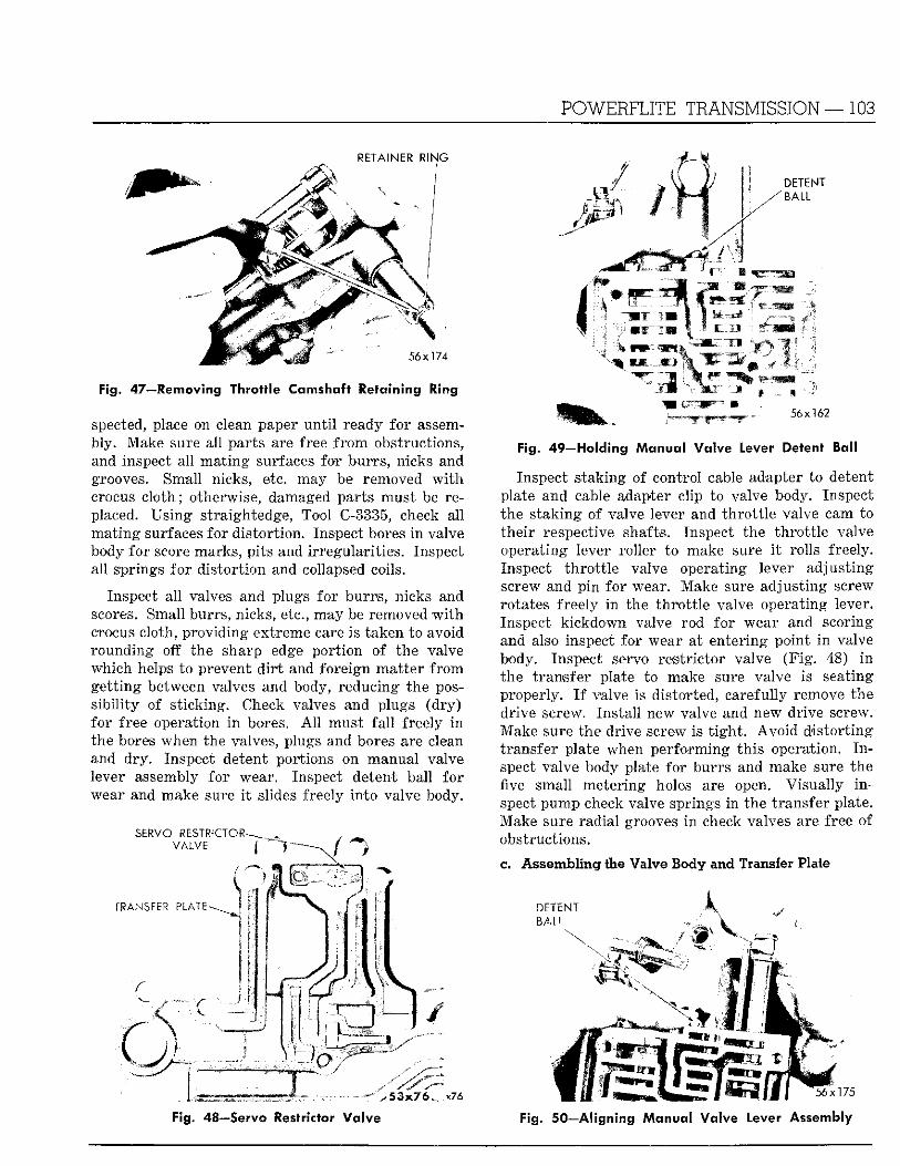
RETAINER RING
Fig. 47—Removing Throttle Camshaft Retaining Ring
spected, place on clean paper u n t i l ready fo r assembly. Make sure all par ts are free f r o m obstructions, and inspect al l ma t ing surfaces for burrs , nicks and grooves. Small nicks, etc. may be removed w i t h crocus c lo th ; otherwise, damaged parts must be replaced. Us ing straightedge, Tool C-3335, check all ma t ing surfaces for d is tor t ion . Inspect bores i n valve body for score marks, p i t s and i r regular i t ies . Inspect all springs f o r d is tor t ion and collapsed coils.
Inspect al l valves and plugs for burrs , nicks and scores. Small burrs , nicks, etc., may be removed w i t h crocus cloth, provid ing extreme care is taken to avoid rounding off the sharp edge por t ion of the valve which helps to prevent d i r t and fore ign mat te r f r o m ge t t ing between valves and body, reducing the poss ib i l i ty of s t icking. Check valves and plugs (d ry ) for free operation i n bores. A l l must f a l l freely i n the bores when the valves, plugs and bores are clean and dry . Inspect detent portions on manual valve lever assembly fo r wear. Inspect detent ball fo r wear and make sure i t slides freely in to valve body.
Fig. 48—Servo Restrictor Valve
POWERFLITE TRANSMISSION—103
Fig. 49—Holding Manual Valve Lever Detent Ball
Inspect s taking of control cable adapter to detent plate and cable adapter clip to valve body. Inspect the .staking of valve lever and th ro t t l e valve cam to the i r respective shafts. Inspect the t h ro t t l e valve operat ing lever roller to make sure i t rolls freely. Inspect t h ro t t l e valve operating lever adjus t ing screw and pin for wear. Make sure adjus t ing screw rotates freely i n the t h ro t t l e valve operating lever. Inspect k ickdown valve rod for wear and scoring and also inspect for wear at entering point i n valve body. Inspect servo res t r ic tor valve (F ig . 48) i n the t ransfer plate to make sure valve is seating properly. I f valve is distorted, carefully remove the drive screw. Ins ta l l new valve and new drive screw. Make sure the drive screw is t i g h t . A v o i d d i s to r t ing t ransfer plate when per forming th i s operation. I n spect valve body plate for burrs and make sure the five small meter ing holes are open. Visua l ly i n spect pump check valve springs i n the t ransfer plate. Make sure radial grooves i n check valves are free of obstructions.
c. Assembling the Valve Body and Transfer Plate
DETENT
Fig. 50—Aligning Manual Va lve Lever Assembly
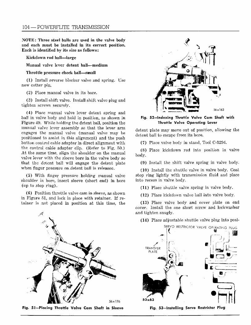
104 —POWERFLITE TRANSMISSION
.NOTE: Three steel balls are used In the valve body and each must be installed i n i t s correct posit ion. Each is i d e n t i i e i by i t s size as fo l lows:
K ickdown rod ball—large
Manual valve lever detent bal l—medium
Thro t t l e pressure check ball—-small
(1) Ins ta l l reverse blocker valve and spring. Use new cotter p in .
(2 ) Place manual valve i n i t s bore.
(3 ) Ins ta l l sh i f t valve. Ins ta l l sh i f t valve p lug and t igh ten screws securely.
(4 ) Place manual valve lever detent spring and ball i n valve body and hold i n position, as shown i n F igure 49. Whi l e holding the detent ball , position the manual valve lever assembly so tha t the lever a r m engages the manual valve (manual valve may be positioned to -assist i n th is al ignment) and the push bu t ton control cable adapter i n direct al ignment w i t h the control cable adapter clip. (Eefer to F i g . 50.) A t the same t ime, al ign the shoulder on the manual valve lever w i t h the sleeve bore i n the valve body so t h a t the detent bal l w i l l engage the detent plate when finger pressure on .detent bal l is released.
(5 ) W i t h finger pressure holding manual valve shoulder i n bore, insert sleeve (short end) i n bore (up to stop r i n g ) .
(6 ) Posit ion th ro t t l e valve cam in. sleeve, as shown i n F igure 51, and lock i n place w i t h retainer. I f reta iner is not placed i n posit ion at th i s t ime, the
Tf 0 :
56x163
Fig. 52—Indexing Throttle Valve Cam Shaft wi th Throttle Valve Operating lever
detent plate may move out of position, a l lowing the detent ball to escape f r o m i ts bore.
(7 ) Place valve body i n stand, Tool C-3294.
(8 ) Place k ickdown rod in to position i n valve body.
(9 ) Ins ta l l the shi f t valve spr ing i n valve body.
(10) Ins ta l l the shutt le valve i n valve body. Coat stop r i n g l i g h t l y w i t h transmission f l u i d and place in to recess i n valve body.
(11) Place shutt le valve spr ing i n valve body.
(12) Place kickdown valve ball in to valve body.
(13) Place valve body and cover plate on end cover. Ins ta l l the one short screw and lockwasher and t i gh ten snugly.
(14) Place adjustable shutt le valve plug in to posi-
SERVO RESTRICTOR VALVE OPERATING PLUG
MM mm 56x176
Fig. 51—Placing Throttle Valve Cam Shaft in Sleeve
/ TRANSFER
PLATE . ; y ^
mm
S g | | |
Fig. 53—Installing Servo Restrictor Plug
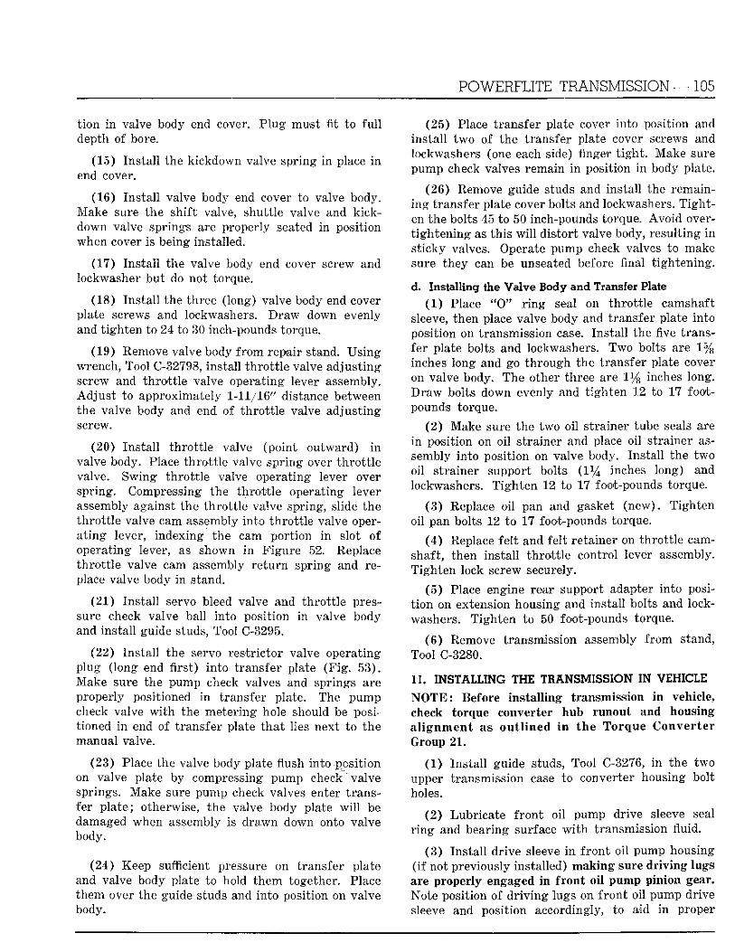
POWERFLITE TRANSMISSION—105
t i o n i n valve body end cover. P lug must fit to f u l l depth of bore.
(15) Ins ta l l the k ickdown valve spr ing i n place i n end cover.
(16) Ins ta l l valve body end cover to valve body. Make sure the shi f t valve, shutt le valve and k ick-down valve springs are properly seated i n posit ion when cover is being installed.
(17) Ins ta l l the valve body end cover screw and lockwasher bu t do not torque.
(18) Ins ta l l the three (long) valve body end cover plate screws and lockwashers. D r a w down evenly and t igh ten to 24 to 30 inch-pounds torque.
(19) Remove valve body f r o m repair stand. Us ing wrench, Tool C-32798, instal l t h ro t t l e valve adjus t ing screw and t h ro t t l e valve operat ing lever assembly. Ad jus t to approximately 1-11/16" distance between the valve body and end of t h ro t t l e valve adjus t ing screw.
(20) Ins ta l l t h ro t t l e valve (point ou tward) i n valve body. Place th ro t t l e valve spr ing over t h r o t t l e valve. Swing th ro t t l e valve operating lever over spring. Compressing the t h r o t t l e operating lever assembly against the t h ro t t l e valve spring, slide the th ro t t l e valve cam assembly in to th ro t t l e valve opera t ing lever, indexing the cam por t ion i n slot of operating lever, as shown i n F igure 52. Replace th ro t t l e valve cam assembly r e t u r n spr ing and replace valve body i n stand.
(21) Ins ta l l servo bleed valve and th ro t t l e pressure check valve ball into posit ion i n valve body and ins ta l l guide studs, Tool C-3295.
(22) Ins ta l l the servo res t r ic tor valve operat ing plug ( long end f i rs t ) in to t ransfer plate ( F i g . 53) . Make sure the pump check valves and springs are properly positioned i n transfer plate. The pump check valve w i t h the meter ing hole should be positioned i n end of t ransfer plate t h a t lies next to the manual valve.
(23) Place the valve body plate flush into posi t ion on valve plate by compressing pump check "valve springs. Make sure pump check valves enter t ransfer p la te ; otherwise, the valve body plate w i l l be damaged when assembly is d rawn down onto valve body.
(24) Keep sufficient pressure on transfer plate and valve body plate to hold them together. Place them over the guide studs and in to position on valve body.
(25) Place t ransfer plate cover in to posit ion and ins ta l l two of the transfer plate cover screws and lockwashers (one each side) finger t i g h t . Make sure pump check valves remain i n position i n body plate.
(26) Remove guide studs and insta l l the remaini n g t ransfer plate cover bolts and lockwashers. T i g h t en the bolts 45 to 50 inch-pounds torque. A v o i d overt igh ten ing as th is w i l l d is tor t valve body, resul t ing i n s t icky valves. Operate pump check valves to make sure they can be unseated before final t igh ten ing .
d. Installing the Valve Body and Transfer Plate (1 ) Place " 0 " r i n g seal on th ro t t l e camshaft
sleeve, then place valve body and transfer plate in to posit ion on transmission case. Ins ta l l the five transfer plate bolts and lockwashers. Two bolts are 1 % inches long and go th rough the transfer plate cover on valve body. The other three are 1 % inches long. D r a w bolts down evenly and t i gh ten 12 to 17 footpounds torque.
( 2 ) Make sure the two oi l strainer tube seals are i n posit ion on oi l strainer and place oi l s trainer assembly in to posit ion on valve body. Ins ta l l the two oil s t rainer support bolts ( 1 % inches long) and lockwashers. ' T igh t en 12 to 17 foot-pounds torque.
( 3 ) Replace oi l pan and gasket (new) . T igh ten oil pan bolts 12 to 17 foot-pounds torque.
( 4 ) Replace fe l t and fel t retainer on th ro t t l e camshaft, then ins ta l l t h ro t t l e control lever assembly. T igh ten lock screw securely.
(5 ) Place engine rear support adapter in to posit i on on extension housing and insta l l bolts and lockwashers. T igh ten to 50 foot-pounds torque.
( 6 ) Remove transmission assembly f r o m stand, Tool C-3280.
11. INSTALLING THE TRANSMISSION IN VEHICLE' N O T E : Before installing transmission in vehicle, check torque converter hub runout and housing al ignment as outlined in the Torque Converter Group 2 1 .
(1 ) Ins ta l l guide studs, Tool C-3276, i n the two upper transmission case to converter housing bolt holes.
(2 ) Lubr icate f r o n t o i l pump drive sleeve seal r i n g and bearing surface w i t h transmission fluid.
(3 ) Ins ta l l dr ive sleeve i n f ron t o i l pump housing ( i f not previously installed) making sure driving lugs are properly engaged i n front oil pump pinion gear. Note position of d r i v i n g lugs on f r o n t oi l pump drive sleeve and position accordingly, to aid i n proper
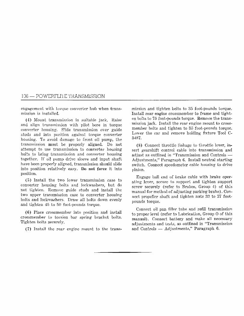
106 — POWERFLITE TRANSMISSION
engagement w i t h torque converter hub when transmission is installed.
(4 ) Mount transmission i n suitable jack. Raise and al ign transmission w i t h pi lot bore i n torque converter housing. Slide transmission over guide studs and into position against torque converter housing. To avoid damage to f ron t oi l pump, the transmission must be properly aligned. Do not a t tempt to use transmission to converter housing bolts to b r i ng transmission and converter housing together. I f oil pump drive sleeve and input shaft have been properly aligned, transmission should slide into position re la t ively easy. Do not force i t in to position.
(5 ) Ins ta l l the two lower transmission case to converter housing bolts and lockwashers, bu t do not t ighten . Remove guide studs and ins ta l l the two upper transmission case to converter housing bolts and lockwashers. Draw all bolts down evenly and t igh ten 45 to 50 foot-pounds torque.
(6 ) Place crossmember in to position and ins ta l l crossmember to tors ion bar spr ing bracket bolts. T ighten bolts securely.
(7 ) Ins ta l l the rear engine mount to the trans
mission and t igh ten bolts to 35 foot-pounds torque. Ins ta l l rear engine crossmember to frame and t i g h t en bolts to 75 foot-pounds torque. Remove the transmission 'jack. Ins ta l l the rear engine mount to cross-member bolts and t igh ten to 35 foot-pounds torque. Lower the ear and remove holding f ixture Tool C-3487.
(8) Connect th ro t t l e linkage to th ro t t l e lever, i n sert gearshift control cable into transmission and adjust as outlined in "Transmission and Controls — Adjustments ," Paragraph 6. Ins ta l l neutral s t a r t ing switch. Connect speedometer cable housing to drive pinion.
Engage ball end of brake cable w i t h brake opera t ing lever, secure to support and t igh ten support screw securely (refer to Brakes, Group 4) of th i s manual fo r method of adjust ing park ing brake) . Connect propeller shaft and t igh ten nuts 33 to 37 footpounds torque.
Connect oil pan filler tube and refill transmission to proper level (refer to Lubr ica t ion , Group 0 of th i s manual) . Connect ba t tery and make al l necessary adjustments and tests, as outlined i n "Transmission and Controls — Adjus tmen t s / ' Paragraph 6.
WHEELS, BEARINGS AND TIRES — 1
Group 22 WHEELS, BEARINGS AND T I R E S
CONTENTS
Care of Tires
Wheel Balance
Paragraph Page
12 5
15 8
8 4
13 6
14 7
1 2
10 5
9 4
11 5
DATA AND SPECIFICATIONS M O D E L S D E S O T O (PS-1, PS-3) W I N D S O R (PC-1)
W H E E L S Type _ Steel Disc R i m Drop Center—Safety Wheel Size 14 x 5 i / 2 K 14 x 5 y 2 K
14 x GK (Town and Count ry ) Number of Wheel Nu t s 5 Stud Hole Circle W Stud Size y 2 " -20
T I R E S Type Super Cushion Tubeless Size 8 x 14 8.00 x 14
8.50 x 14 Optional 8.50 x 14 (Town and Count ry ) P l y 4 Standard Tread T w i n Gr ip
T I R E P R E S S U R E S - C O L D Pounds—Rear 24—Town and Country*
Rear 22 24 F ron t 22
* W i t h Town & Country f u l l y loaded, increase rear t i r e cold pressure to 28 pounds. Capt ive-Air t i res are optional equipment on Town & Country Wagons 3-seat Models only.
(8.50 x 14 on Model PC-1 and 9.00 x 14 on Model PC-3.)