Embed Size (px)
Citation preview
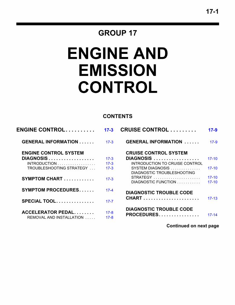
17-1
GROUP 17
ENGINE AND EMISSION CONTROL
CONTENTS
ENGINE CONTROL. . . . . . . . . . 17-3
GENERAL INFORMATION . . . . . . 17-3
ENGINE CONTROL SYSTEM DIAGNOSIS . . . . . . . . . . . . . . . . . . 17-3
INTRODUCTION . . . . . . . . . . . . . . . . . . 17-3TROUBLESHOOTING STRATEGY . . . 17-3
SYMPTOM CHART . . . . . . . . . . . . 17-3
SYMPTOM PROCEDURES. . . . . . 17-4
SPECIAL TOOL. . . . . . . . . . . . . . . 17-7
ACCELERATOR PEDAL. . . . . . . . 17-8REMOVAL AND INSTALLATION . . . . . 17-8
CRUISE CONTROL . . . . . . . . . 17-9
GENERAL INFORMATION . . . . . . 17-9
CRUISE CONTROL SYSTEM DIAGNOSIS . . . . . . . . . . . . . . . . . . 17-10
INTRODUCTION TO CRUISE CONTROL SYSTEM DIAGNOSIS . . . . . . . . . . . . . . 17-10DIAGNOSTIC TROUBLESHOOTING STRATEGY . . . . . . . . . . . . . . . . . . . . . . 17-10DIAGNOSTIC FUNCTION . . . . . . . . . . . 17-10
DIAGNOSTIC TROUBLE CODE CHART . . . . . . . . . . . . . . . . . . . . . . 17-13
DIAGNOSTIC TROUBLE CODE PROCEDURES. . . . . . . . . . . . . . . . 17-14
Continued on next page
17-2
SYMPTOM CHART . . . . . . . . . . . . 17-38
SYMPTOM PROCEDURES. . . . . . 17-39
DATA LIST REFERENCE TABLE. 17-61
ECM TERMINAL VOLTAGE REFERENCE CHART FOR CRUISE CONTROL SYSTEM OPERATION . . . . . . . . . . . . . . . . . 17-62
SPECIAL TOOLS. . . . . . . . . . . . . . 17-63
ON-VEHICLE SERVICE. . . . . . . . . 17-65CRUISE CONTROL SWITCH CHECK . 17-65CRUISE CONTROL SYSTEM COMPONENT CHECK . . . . . . . . . . . . . 17-67
CRUISE CONTROL SWITCH . . . . 17-68REMOVAL AND INSTALLATION . . . . . 17-68
EMISSION CONTROL MFI - T/C 17-68
GENERAL INFORMATION . . . . . . 17-68
SERVICE SPECIFICATIONS. . . . . 17-68
DIAGNOSIS . . . . . . . . . . . . . . . . . . 17-68
SPECIAL TOOL. . . . . . . . . . . . . . . 17-68
VACUUM HOSES . . . . . . . . . . . . . 17-69VACUUM HOSE ROUTING. . . . . . . . . . 17-69VACUUM CIRCUIT DIAGRAM . . . . . . . 17-70VACUUM HOSE INSTALLATION . . . . . 17-71VACUUM HOSE CHECK. . . . . . . . . . . . 17-71
POSITIVE CRANKCASE VENTILATION SYSTEM. . . . . . . . . 17-71
GENERAL INFORMATION (POSITIVE CRANKCASE VENTILATION SYSTEM) 17-71COMPONENT LOCATION. . . . . . . . . . . 17-72CRANKCASE VENTILATION SYSTEM CHECK. . . . . . . . . . . . . . . . . . . . . . . . . . 17-72POSITIVE CRANKCASE VENTILATION (PCV) VALVE CHECK . . . . . . . . . . . . . . 17-72
EVAPORATIVE EMISSION CONTROL SYSTEM . . . . . . . . . . . . . . . . . . . . . 17-73
GENERAL INFORMATION (EVAPORATIVE EMISSION SYSTEM) . . . . . . . . . . . . . . . 17-73COMPONENT LOCATION. . . . . . . . . . . 17-75PURGE CONTROL SYSTEM CHECK (PURGE FLOW CHECK) . . . . . . . . . . . . 17-75EVAPORATIVE EMISSION PURGE SOLENOID CHECK . . . . . . . . . . . . . . . . 17-76MASS AIRFLOW SENSOR CHECK . . . 17-77INTAKE AIR TEMPERATURE SENSOR 1 CHECK. . . . . . . . . . . . . . . . . . . . . . . . . . 17-77BAROMETRIC PRESSURE SENSOR CHECK. . . . . . . . . . . . . . . . . . . . . . . . . . 17-77ENGINE COOLANT TEMPERATURE SENSOR CHECK. . . . . . . . . . . . . . . . . . 17-77THROTTLE POSITION SENSOR CHECK 17-77CRANKSHAFT POSITION SENSOR CHECK. . . . . . . . . . . . . . . . . . . . . . . . . . 17-77
EVAPORATIVE EMISSION CANISTER AND FUEL TANK PRESSURE RELIEF VALVE . . . . . 17-78
REMOVAL AND INSTALLATION. . . . . . 17-78INSPECTION . . . . . . . . . . . . . . . . . . . . . 17-79
CATALYTIC CONVERTER . . . . . . 17-80REMOVAL AND INSTALLATION. . . . . . 17-80
ENGINE CONTROLENGINE AND EMISSION CONTROL 17-3
ENGINE CONTROLGENERAL INFORMATION
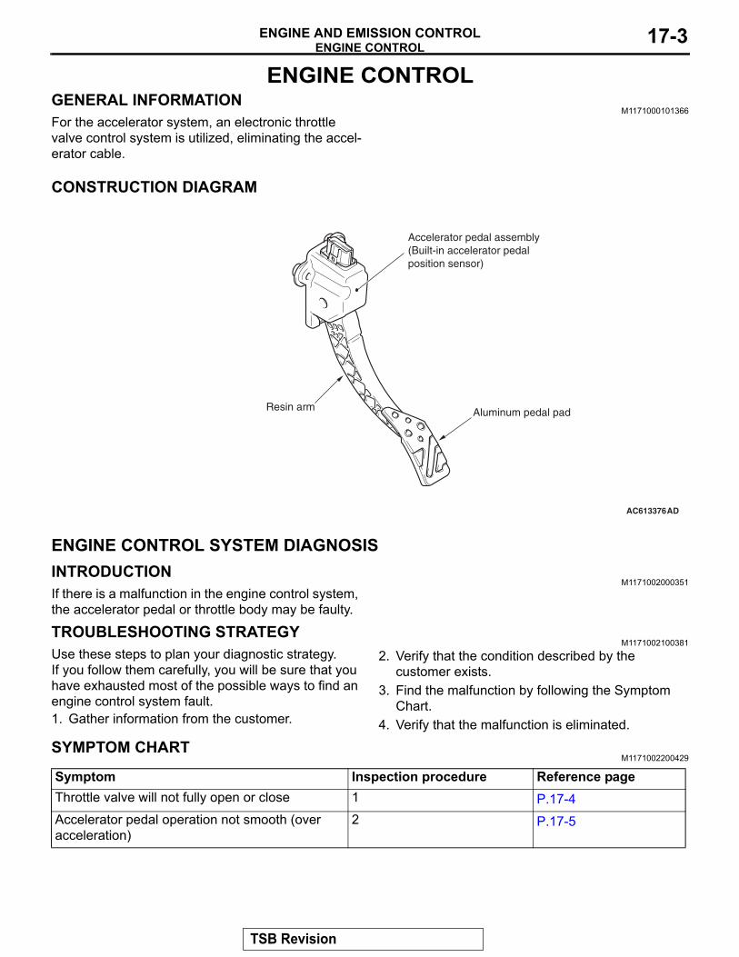
M1171000101366For the accelerator system, an electronic throttle valve control system is utilized, eliminating the accel-erator cable.
CONSTRUCTION DIAGRAM
ENGINE CONTROL SYSTEM DIAGNOSISINTRODUCTION
M1171002000351If there is a malfunction in the engine control system, the accelerator pedal or throttle body may be faulty.
TROUBLESHOOTING STRATEGYM1171002100381
Use these steps to plan your diagnostic strategy.If you follow them carefully, you will be sure that you have exhausted most of the possible ways to find an engine control system fault.1. Gather information from the customer.
2. Verify that the condition described by the customer exists.
3. Find the malfunction by following the Symptom Chart.
4. Verify that the malfunction is eliminated.
SYMPTOM CHARTM1171002200429
AC613376AD
Accelerator pedal assembly(Built-in accelerator pedalposition sensor)
Resin arm Aluminum pedal pad
Symptom Inspection procedure Reference pageThrottle valve will not fully open or close 1 P.17-4Accelerator pedal operation not smooth (over acceleration)
2 P.17-5
TSB Revision
ENGINE CONTROLENGINE AND EMISSION CONTROL17-4
SYMPTOM PROCEDURES
Inspection Procedure 1: Throttle Valve will not Fully Open or Close
.
COMMENTThe throttle body or accelerator pedal position sen-sor is suspected..
TROUBLESHOOTING HINTS (THE MOST LIKELY CAUSES FOR THIS CASE:)
• Malfunction of the throttle body.• Malfunction of the accelerator pedal position sen-
sor.• Malfunction of the engine control module (ECM).
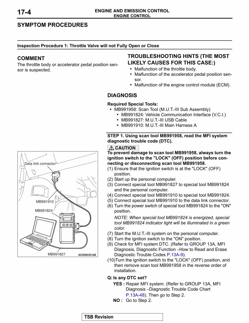
DIAGNOSISRequired Special Tools:• MB991958: Scan Tool (M.U.T.-III Sub Assembly)
• MB991824: Vehicle Communication Interface (V.C.I.)• MB991827: M.U.T.-III USB Cable• MB991910: M.U.T.-III Main Harness A
STEP 1. Using scan tool MB991958, read the MFI system diagnostic trouble code (DTC).
CAUTIONTo prevent damage to scan tool MB991958, always turn the ignition switch to the "LOCK" (OFF) position before con-necting or disconnecting scan tool MB991958.(1) Ensure that the ignition switch is at the "LOCK" (OFF)
position.(2) Start up the personal computer.(3) Connect special tool MB991827 to special tool MB991824
and the personal computer.(4) Connect special tool MB991910 to special tool MB991824.(5) Connect special tool MB991910 to the data link connector.(6) Turn the power switch of special tool MB991824 to the "ON"
position.NOTE: When special tool MB991824 is energized, special tool MB991824 indicator light will be illuminated in a green color.
(7) Start the M.U.T.-III system on the personal computer.(8) Turn the ignition switch to the "ON" position.(9) Check for MFI system DTC. (Refer to GROUP 13A, MFI
Diagnosis, Diagnostic Function − How to Read and Erase Diagnostic Trouble Codes P.13A-9).
(10)Turn the ignition switch to the "LOCK" (OFF) position, and then remove scan tool MB991958 in the reverse order of installation.
Q: Is any DTC set?YES : Repair MFI system. (Refer to GROUP 13A, MFI
Diagnosis − Diagnostic Trouble Code Chart P.13A-48). Then go to Step 2.
NO : Go to Step 2.
AC608435
Data link connector
MB991827
MB991824
MB991910
AB
TSB Revision
ENGINE CONTROLENGINE AND EMISSION CONTROL 17-5
STEP 2. Retest the system.Q: Does the throttle valve fully open and close?
YES : The procedure is complete.NO : Return to Step 1.
Inspection Procedure 2: Accelerator Pedal Operation not Smooth (Over Acceleration)
.
COMMENTThe accelerator pedal, its installation condition or the accelerator pedal position sensor is suspected..
TROUBLESHOOTING HINTS (THE MOST LIKELY CAUSES FOR THIS CASE:)
• Malfunction of the accelerator pedal.• Incorrectly installed accelerator pedal.• Malfunction of the accelerator pedal position sen-
sor.
DIAGNOSISRequired Special Tools:• MB991958: Scan Tool (M.U.T.-III Sub Assembly)
• MB991824: V.C.I.• MB991827: M.U.T.-III USB Cable• MB991910: M.U.T.-III Main Harness A
STEP 1. Check if the accelerator pedal is installed correctly.Q: Is the accelerator pedal installed correctly?
YES : Go to Step 2.NO : Remove and reinstall the accelerator pedal (Refer to
P.17-8). Then go to Step 3.
TSB Revision
ENGINE CONTROLENGINE AND EMISSION CONTROL17-6
STEP 2. Using scan tool MB991958, read the MFI system DTC.
CAUTIONTo prevent damage to scan tool MB991958, always turn the ignition switch to the "LOCK" (OFF) position before con-necting or disconnecting scan tool MB991958.(1) Ensure that the ignition switch is at the "LOCK" (OFF)
position.(2) Start up the personal computer.(3) Connect special tool MB991827 to special tool MB991824
and the personal computer.(4) Connect special tool MB991910 to special tool MB991824.(5) Connect special tool MB991910 to the data link connector.(6) Turn the power switch of special tool MB991824 to the "ON"
position.NOTE: When special tool MB991824 is energized, special tool MB991824 indicator light will be illuminated in a green color.
(7) Start the M.U.T.-III system on the personal computer.(8) Turn the ignition switch to the "ON" position.(9) Check for MFI system DTC. (Refer to GROUP 13A, MFI
Diagnosis, Diagnostic Function − How to Read and Erase Diagnostic Trouble Codes P.13A-9).
(10)Turn the ignition switch to the "LOCK" (OFF) position, and then remove scan tool MB991958 in the reverse order of installation.
Q: Is any DTC set?YES : Repair MFI system (Refer to GROUP 13A, MFI
Diagnosis − Diagnostic Trouble Code Chart P.13A-48). Then go to Step 3.
NO : Go to Step 3.
STEP 3. Retest the system.Q: Does the accelerator pedal work normally?
YES : The procedure is complete.NO : Return to Step 1.
AC608435
Data link connector
MB991827
MB991824
MB991910
AB
TSB Revision
ENGINE CONTROLENGINE AND EMISSION CONTROL 17-7
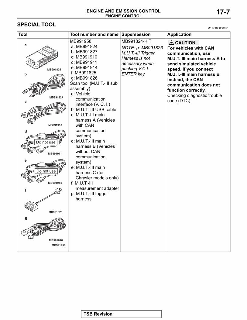
SPECIAL TOOLM1171000600216
Tool Tool number and name Supersession ApplicationMB991958a: MB991824b: MB991827c: MB991910d: MB991911e: MB991914f: MB991825g: MB991826Scan tool (M.U.T.-III sub assembly)a: Vehicle
communication interface (V. C. I.)
b: M.U.T.-III USB cablec: M.U.T.-III main
harness A (Vehicles with CAN communication system)
d: M.U.T.-III main harness B (Vehicles without CAN communication system)
e: M.U.T.-III main harness C (for Chrysler models only)
f: M.U.T.-III measurement adapter
g: M.U.T.-III trigger harness
MB991824-KITNOTE: g: MB991826 M.U.T.-III Trigger Harness is not necessary when pushing V.C.I. ENTER key.
CAUTIONFor vehicles with CAN communication, use M.U.T.-III main harness A to send simulated vehicle speed. If you connect M.U.T.-III main harness B instead, the CAN communication does not function correctly.Checking diagnostic trouble code (DTC)
MB991910
MB991826
MB991958
MB991911
MB991914
MB991824
MB991827
MB991825
Do not use
a
b
c
d
e
f
g
Do not use
TSB Revision
ENGINE CONTROLENGINE AND EMISSION CONTROL17-8
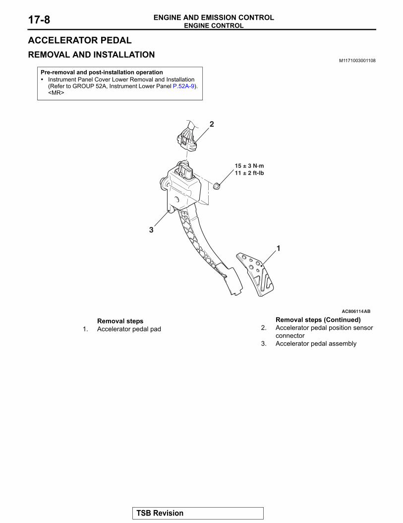
ACCELERATOR PEDALREMOVAL AND INSTALLATION
M1171003001108
Pre-removal and post-installation operation• Instrument Panel Cover Lower Removal and Installation
(Refer to GROUP 52A, Instrument Lower Panel P.52A-9). <MR>
AC806114AB
1
3
2
15 ± 3 N·m11 ± 2 ft-lb
Removal steps 1. Accelerator pedal pad 2. Accelerator pedal position sensor
connector3. Accelerator pedal assembly
Removal steps (Continued)
TSB Revision
CRUISE CONTROLENGINE AND EMISSION CONTROL 17-9
CRUISE CONTROLGENERAL INFORMATION
M1172000101392
By using the cruise control system, the driver can drive at preferred speeds in a range of approximately 40 to 200 km/h (25 to 125 mph) without depressing the accelerator pedal.
For this cruise control system, in conjunction with the electronic throttle valve control system, the engine control module (ECM) electronically controls the throttle valve.
CONSTRUCTION DIAGRAM
AC902079
AC708696
AC708692
CANCEL
ACCRES
ONOFF
COASTSET
AC708694
AC708695
AC902078
Cruise control switch
Data link connector
Hoodlockreleasehandle
AB
Clutch switch <M/T>
Stoplight switch
Accelerator pedal(Built-in accelerator pedal position sensor)
Engine controlmodule (ECM)
"CRUISE" indicator light
Transaxle assembly[Built-in twin clutch-sportronic shifttransmission-ECU(TC-SST-ECU)]<TC-SST>
Throttle body(Built-in throttle positionsensor and throttleactuator control motor)
Hydraulic unit Assembly(Built-in ASC-ECU)
Shift lever assembly(Built-in shift lever ECU)<TC-SST>
Steering wheel
TSB Revision
CRUISE CONTROLENGINE AND EMISSION CONTROL17-10
CRUISE CONTROL SYSTEM DIAGNOSISINTRODUCTION TO CRUISE CONTROL SYSTEM DIAGNOSIS
M1172003300358
The cruise control system allows driving without stepping on the accelerator pedal by setting a ran-dom speed between approximately 40 km/h (25 mph) and 200 km/h (125 mph). Malfunctions in this system can be investigated by the following meth-ods.
CRUISE CONTROL SYSTEM DIAGNOSTIC TROUBLE CODESThe cruise control system consists of the ECM, con-trol switches and sensors. The control switches and sensors monitor the state of the vehicle. The ECM controls the throttle valve opening angle in the throt-tle body in accordance with the input signals from the switches and sensors. If the ECM detects a malfunc-tion on any of those components, the ECM estimates where the problem may be occurring, and will set a diagnostic trouble code (DTC). DTCs cover the cruise control switch, stoplight switch and ECM.
DIAGNOSTIC TROUBLESHOOTING STRATEGYM1172002000826
Use these steps to plan your diagnostic strategy. If you follow them carefully, you will check most of the possible causes of a cruise control system malfunc-tion.1. Gather information from the customer.2. Verify that the condition described by the
customer exists.3. Check the vehicle for any cruise control system
DTC (Refer to P.17-10, Diagnostic Function − How to Read Diagnostic Trouble Codes).
4. If you cannot verify the condition and there are no cruise control system DTCs, the malfunction may be intermittent (Refer to GROUP 00, How to Use Troubleshooting/Inspection Service Points − How to Cope with Intermittent Malfunctions P.00-15).
5. If you can verify the condition but there are no cruise control system DTCs, find the fault (Refer to P.17-38, Symptom Chart).
6. If there is an cruise control system DTC, record the number of the code, then erase the code (Refer to P.17-10, Diagnostic Function − How to Erase Diagnostic Trouble Codes).
7. Re-create the cruise control system DTC set conditions to see if the same cruise control system DTC will set again (Refer to P.17-10, Diagnostic Function − How to Read Diagnostic Trouble Codes).
• If the same cruise control system DTC sets again, perform the diagnostic procedures for the set code (Refer to P.17-13, Diagnostic Trouble Code Chart).
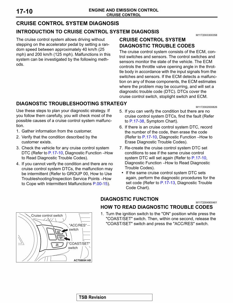
DIAGNOSTIC FUNCTIONM1172004900461
HOW TO READ DIAGNOSTIC TROUBLE CODES1. Turn the ignition switch to the "ON" position while press the
"COAST/SET" switch. Then, within one second, release the "COAST/SET" switch and press the "ACC/RES" switch.
CANCEL
ACCRES
ONOFF
COASTSET
AC708694 AB
Cruise control switch
"ACC/RES"switch
"COAST/SET"switch
TSB Revision
CRUISE CONTROLENGINE AND EMISSION CONTROL 17-11
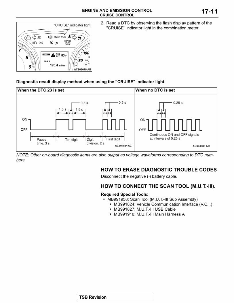
2. Read a DTC by observing the flash display pattern of the "CRUISE" indicator light in the combination meter.
Diagnostic result display method when using the "CRUISE" indicator light
NOTE: Other on-board diagnostic items are also output as voltage waveforms corresponding to DTC num-bers.
HOW TO ERASE DIAGNOSTIC TROUBLE CODESDisconnect the negative (−) battery cable.
HOW TO CONNECT THE SCAN TOOL (M.U.T.-III).Required Special Tools:• MB991958: Scan Tool (M.U.T.-III Sub Assembly)
• MB991824: Vehicle Communication Interface (V.C.I.)• MB991827: M.U.T.-III USB Cable• MB991910: M.U.T.-III Main Harness A
AC902078 AB
"CRUISE" indicator light
When the DTC 23 is set When no DTC is set
AC604884
ON
OFF
Pausetime: 3 s
Ten digit Digitdivision: 2 s
First digit
0.5 s
1.5 s
AC
1.5 s
0.5 s
AC604885 AC
ON
OFF
0.25 s
Continuous ON and OFF signalsat intervals of 0.25 s
TSB Revision
CRUISE CONTROLENGINE AND EMISSION CONTROL17-12
CAUTIONTo prevent damage to scan tool MB991958, always turn the ignition switch to the "LOCK" (OFF) position before con-necting or disconnecting scan tool MB991958.1. Start up the personal computer.2. Connect special tool MB991827 to special tool MB991824
and the personal computer.3. Connect special tool MB991910 to special tool MB991824.4. Connect special tool MB991910 to the data link connector.5. Turn the power switch of special tool MB991824 to the "ON"
position.NOTE: When special tool MB991824 is energized, special tool MB991824 indicator light will be illuminated in green color.
6. Start the M.U.T.-III system on the personal computer.NOTE: Disconnecting scan tool MB991958 is the reverse of the connecting sequence, making sure that the ignition switch is at the "LOCK" (OFF) position.
HOW TO READ DATA LISTRequired Special Tools:• MB991958: Scan Tool (M.U.T.-III Sub Assembly)
• MB991824: V.C.I.• MB991827: M.U.T.-III USB Cable• MB991910: M.U.T.-III Main Harness A
1. Connect scan tool MB991958 to the data link connector.2. Turn the ignition switch to the "ON" position.3. Select "System Select" from the start-up screen.4. Select "From 2006 MY" of "Model Year." When the "Vehicle
Information" is displayed, check the contents.5. "Select "AUTO CRUISE" from "System List", and press the
"OK" button.NOTE: When the "Loading Option Setup" list is displayed, check the applicable item.
6. Select the "MITSUBISHI."7. Select the "Data List."
NOTE: When the "Data List Reference Table" button is selected, the service data reference table is displayed, and the normal values can be checked.
AC608435
Data link connector
MB991827
MB991824
MB991910
AB
TSB Revision
CRUISE CONTROLENGINE AND EMISSION CONTROL 17-13
HOW TO DIAGNOSE THE CAN BUS LINERequired Special Tools:• MB991958: Scan Tool (M.U.T.-III Sub Assembly)
• MB991824: V.C.I.• MB991827: M.U.T.-III USB Cable• MB991910: M.U.T.-III Main Harness A
1. Connect scan tool MB991958 to the data link connector.2. Turn the ignition switch to the "ON" position.3. Select the "CAN Bus Diagnosis" from the start-up screen.4. When the vehicle information is displayed, confirm that it
matches the vehicle whose CAN bus lines will be diagnosed.
• If they match, go to Step 8.• If not, go to Step 5.
5. Select the "view vehicle information" button.6. Enter the vehicle information and select the "OK" button.7. When the vehicle information is displayed, confirm again
that it matches the vehicle which whose CAN bus lines will be diagnosed.
• If they match, go to Step 8.• If not, go to Step 5.
8. Press the "OK" button.9. When the optional equipment screen is displayed, choose
the one which the vehicle is fitted with, and then select the "OK" button.
DIAGNOSTIC TROUBLE CODE CHARTM1172002200897
Check according to the inspection chart that is appropriate for the DTC.DTC number Inspection Item Reference page15 Cruise control switch system P.17-1422 Stoplight switch system P.17-2723 ECM and its related components P.17-36
TSB Revision
CRUISE CONTROLENGINE AND EMISSION CONTROL17-14
DIAGNOSTIC TROUBLE CODE PROCEDURES
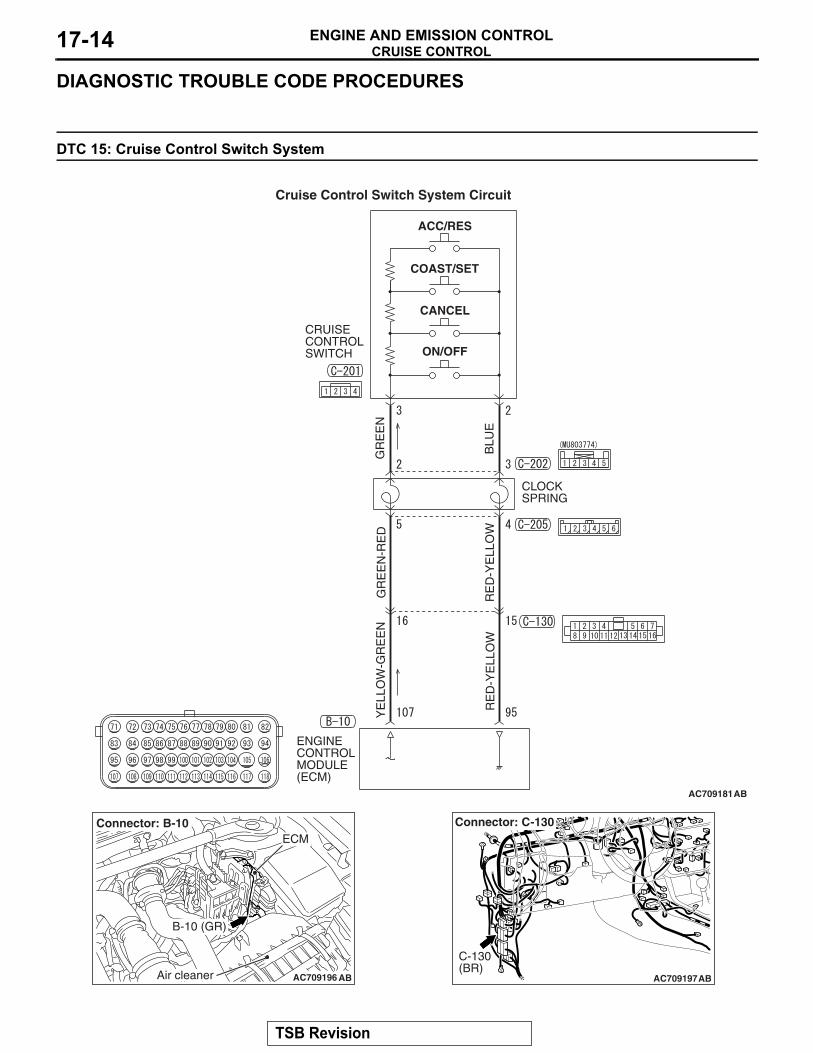
DTC 15: Cruise Control Switch System
AC709181
ON/OFF
CANCEL
COAST/SET
ACC/RES
CLOCK SPRING
ENGINE CONTROL MODULE(ECM)
CRUISE CONTROL SWITCH
GR
EE
NG
RE
EN
-RE
DY
ELL
OW
-GR
EE
N
RE
D-Y
ELL
OW
RE
D-Y
ELL
OW
BLU
E
AB
Cruise Control Switch System Circuit
AC709196 AB
B-10 (GR)
Connector: B-10ECM
Air cleaner AC709197
Connector: C-130
AB
C-130(BR)
TSB Revision
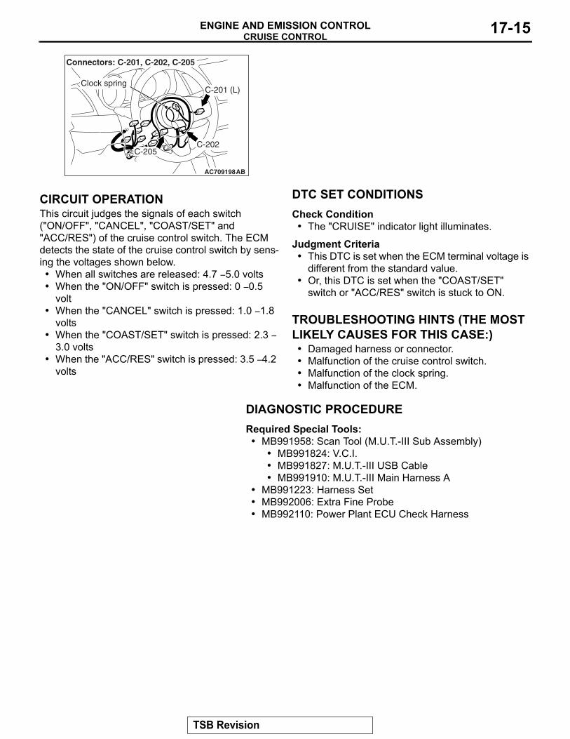
CRUISE CONTROLENGINE AND EMISSION CONTROL 17-15
.
CIRCUIT OPERATIONThis circuit judges the signals of each switch ("ON/OFF", "CANCEL", "COAST/SET" and "ACC/RES") of the cruise control switch. The ECM detects the state of the cruise control switch by sens-ing the voltages shown below.• When all switches are released: 4.7 − 5.0 volts• When the "ON/OFF" switch is pressed: 0 − 0.5
volt • When the "CANCEL" switch is pressed: 1.0 − 1.8
volts • When the "COAST/SET" switch is pressed: 2.3 −
3.0 volts • When the "ACC/RES" switch is pressed: 3.5 − 4.2
volts .
DTC SET CONDITIONSCheck Condition
• The "CRUISE" indicator light illuminates.
Judgment Criteria• This DTC is set when the ECM terminal voltage is
different from the standard value.• Or, this DTC is set when the "COAST/SET"
switch or "ACC/RES" switch is stuck to ON..
TROUBLESHOOTING HINTS (THE MOST LIKELY CAUSES FOR THIS CASE:)
• Damaged harness or connector.• Malfunction of the cruise control switch.• Malfunction of the clock spring.• Malfunction of the ECM.
DIAGNOSTIC PROCEDURERequired Special Tools:• MB991958: Scan Tool (M.U.T.-III Sub Assembly)
• MB991824: V.C.I.• MB991827: M.U.T.-III USB Cable• MB991910: M.U.T.-III Main Harness A
• MB991223: Harness Set• MB992006: Extra Fine Probe• MB992110: Power Plant ECU Check Harness
AC709198AB
C-201 (L)
C-202C-205
Connectors: C-201, C-202, C-205
Clock spring
TSB Revision
CRUISE CONTROLENGINE AND EMISSION CONTROL17-16
STEP 1. Using scan tool MB991958, check the data list item 75: Cancel switch, item 86: Main switch, item 91: Resume switch and item 92: Set switch.
CAUTIONTo prevent damage to scan tool MB991958, always turn the ignition switch to the "LOCK" (OFF) position before con-necting or disconnecting scan tool MB991958.(1) Connect scan tool MB991958 to the data link connector
(Refer to P.17-10.)(2) Turn the ignition switch to the "ON" position.(3) Set scan tool MB991958 to data reading mode for cruise
control system (Refer to P.17-10.)• Item 75: Cancel switch.
• When "CANCEL" switch is pressed, the display on scan tool MB991958 should be "ON".
• When "CANCEL" switch is released, the display on scan tool MB991958 should be "OFF".
• Item 86: Main switch.• When "ON/OFF" switch is pressed, the display on
scan tool MB991958 should be "ON".• When "ON/OFF" switch is pressed again, the display
on scan tool MB991958 should be "OFF".• Item 91: Resume switch.
• When "ACC/RES" switch is pressed, the display on scan tool MB991958 should be "ON".
• When "ACC/RES" switch is released, the display on scan tool MB991958 should be "OFF".
• Item 92: Set switch.• When "COAST/SET" switch is pressed, the display
on scan tool MB991958 should be "ON".• When "COAST/SET" switch is released, the display
on scan tool MB991958 should be "OFF".Q: Is the switch operating properly?
YES : Go to Step 25.NO : Go to Step 2.
AC608435
Data link connector
MB991827
MB991824
MB991910
AB
TSB Revision
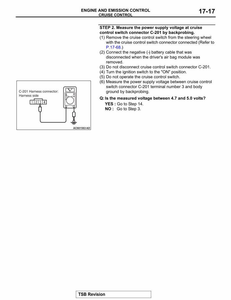
CRUISE CONTROLENGINE AND EMISSION CONTROL 17-17
STEP 2. Measure the power supply voltage at cruise control switch connector C-201 by backprobing.(1) Remove the cruise control switch from the steering wheel
with the cruise control switch connector connected (Refer to P.17-68.)
(2) Connect the negative (−) battery cable that was disconnected when the driver's air bag module was removed.
(3) Do not disconnect cruise control switch connector C-201.(4) Turn the ignition switch to the "ON" position.(5) Do not operate the cruise control switch.(6) Measure the power supply voltage between cruise control
switch connector C-201 terminal number 3 and body ground by backprobing.
Q: Is the measured voltage between 4.7 and 5.0 volts?YES : Go to Step 14.NO : Go to Step 3.
AC601563 AD
C-201 Harness connector:Harness side
TSB Revision
CRUISE CONTROLENGINE AND EMISSION CONTROL17-18
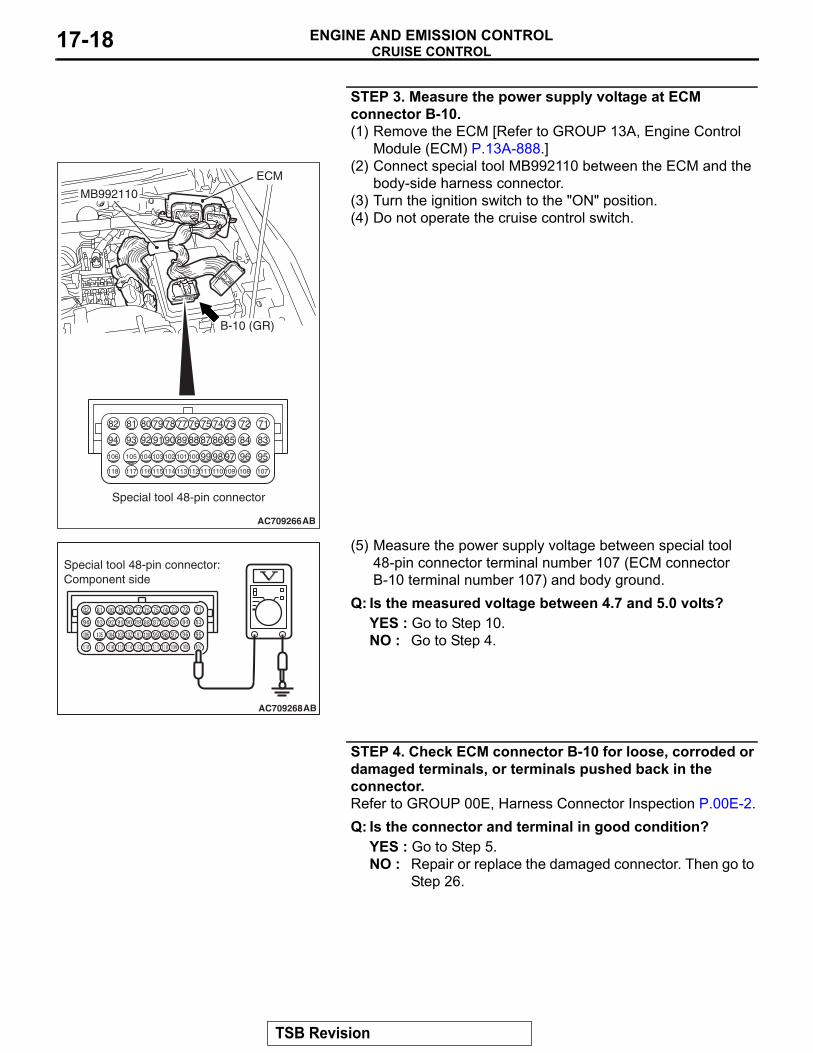
STEP 3. Measure the power supply voltage at ECM connector B-10.(1) Remove the ECM [Refer to GROUP 13A, Engine Control
Module (ECM) P.13A-888.](2) Connect special tool MB992110 between the ECM and the
body-side harness connector.(3) Turn the ignition switch to the "ON" position.(4) Do not operate the cruise control switch.
(5) Measure the power supply voltage between special tool 48-pin connector terminal number 107 (ECM connector B-10 terminal number 107) and body ground.
Q: Is the measured voltage between 4.7 and 5.0 volts?YES : Go to Step 10.NO : Go to Step 4.
STEP 4. Check ECM connector B-10 for loose, corroded or damaged terminals, or terminals pushed back in the connector.Refer to GROUP 00E, Harness Connector Inspection P.00E-2.Q: Is the connector and terminal in good condition?
YES : Go to Step 5.NO : Repair or replace the damaged connector. Then go to
Step 26.
AC709266AB
82 81 80 79 78 77 76 75 74 73 72 71
94 93 92 91 90 89 88 87 86 85 84 83
99 98 97 96 95100101102103104105106
112113114 109 108 107110111115116117118
MB992110
ECM
B-10 (GR)
Special tool 48-pin connector
AC709268AB
Special tool 48-pin connector:Component side
TSB Revision
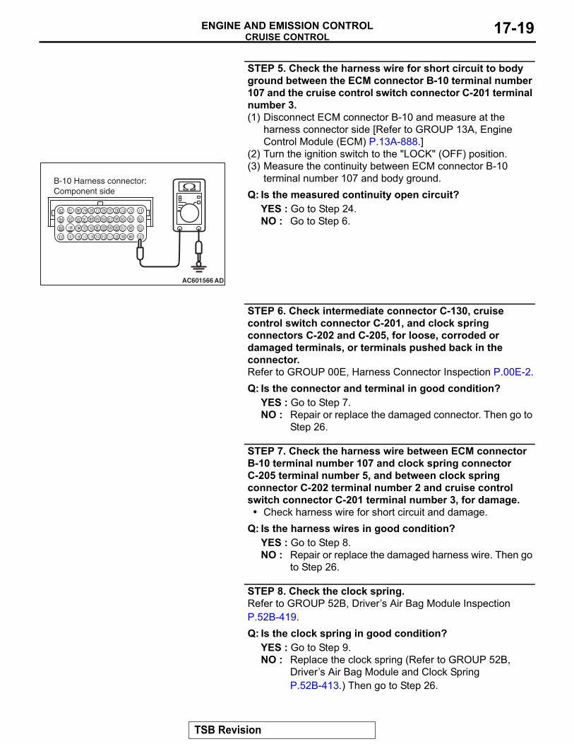
CRUISE CONTROLENGINE AND EMISSION CONTROL 17-19
STEP 5. Check the harness wire for short circuit to body ground between the ECM connector B-10 terminal number 107 and the cruise control switch connector C-201 terminal number 3.(1) Disconnect ECM connector B-10 and measure at the
harness connector side [Refer to GROUP 13A, Engine Control Module (ECM) P.13A-888.]
(2) Turn the ignition switch to the "LOCK" (OFF) position.(3) Measure the continuity between ECM connector B-10
terminal number 107 and body ground.Q: Is the measured continuity open circuit?
YES : Go to Step 24.NO : Go to Step 6.
STEP 6. Check intermediate connector C-130, cruise control switch connector C-201, and clock spring connectors C-202 and C-205, for loose, corroded or damaged terminals, or terminals pushed back in the connector.Refer to GROUP 00E, Harness Connector Inspection P.00E-2.Q: Is the connector and terminal in good condition?
YES : Go to Step 7.NO : Repair or replace the damaged connector. Then go to
Step 26.
STEP 7. Check the harness wire between ECM connector B-10 terminal number 107 and clock spring connector C-205 terminal number 5, and between clock spring connector C-202 terminal number 2 and cruise control switch connector C-201 terminal number 3, for damage.• Check harness wire for short circuit and damage.
Q: Is the harness wires in good condition?YES : Go to Step 8.NO : Repair or replace the damaged harness wire. Then go
to Step 26.
STEP 8. Check the clock spring.Refer to GROUP 52B, Driver’s Air Bag Module Inspection P.52B-419.Q: Is the clock spring in good condition?
YES : Go to Step 9.NO : Replace the clock spring (Refer to GROUP 52B,
Driver’s Air Bag Module and Clock Spring P.52B-413.) Then go to Step 26.
AC601566 AD
B-10 Harness connector:Component side
TSB Revision
CRUISE CONTROLENGINE AND EMISSION CONTROL17-20
STEP 9. Check the cruise control switch.Refer to P.17-67.Q: Is the cruise control switch operating properly?
YES : Go to Step 13.NO : Replace the cruise control switch (Refer to P.17-68.)
Then go to Step 26.
STEP 10. Check ECM connector B-10, intermediate connector C-130, cruise control switch connector C-201, and clock spring connectors C-202 and C-205, for loose, corroded or damaged terminals, or terminals pushed back in the connector.Refer to GROUP 00E, Harness Connector Inspection P.00E-2.Q: Is the connector and terminal in good condition?
YES : Go to Step 11.NO : Repair or replace the damaged connector. Then go to
Step 26.
STEP 11. Check the harness wire between ECM connector B-10 terminal number 107 and clock spring connector C-205 terminal number 5, and between clock spring connector C-202 terminal number 2 and cruise control switch connector C-201 terminal number 3, for damage.• Check harness wire for open circuit and damage.
Q: Is the harness wires in good condition?YES : Go to Step 12.NO : Repair or replace the damaged harness wire. Then go
to Step 26.
STEP 12. Check the clock spring.Refer to GROUP 52B, Driver’s Air Bag Module Inspection P.52B-419.Q: Is the clock spring in good condition?
YES : Go to Step 13.NO : Replace the clock spring (Refer to GROUP 52B,
Driver’s Air Bag Module and Clock Spring P.52B-413.) Then go to Step 26.
TSB Revision
CRUISE CONTROLENGINE AND EMISSION CONTROL 17-21
STEP 13. Using scan tool MB991958, check data list item 75: Cancel switch, item 86: Main switch, item 91: Resume switch and item 92: Set switch.(1) Connect scan tool MB991958 to the data link connector
(Refer to P.17-10.)(2) Turn the ignition switch to the "ON" position.(3) Set scan tool MB991958 to data reading mode for cruise
control system (Refer to P.17-10.)• Item 75: Cancel switch.
• When "CANCEL" switch is pressed, the display on scan tool MB991958 should be "ON".
• When "CANCEL" switch is released, the display on scan tool MB991958 should be "OFF".
• Item 86: Main switch.• When "ON/OFF" switch is pressed, the display on
scan tool MB991958 should be "ON".• When "ON/OFF" switch is pressed again, the display
on scan tool MB991958 should be "OFF".• Item 91: Resume switch.
• When "ACC/RES" switch is pressed, the display on scan tool MB991958 should be "ON".
• When "ACC/RES" switch is released, the display on scan tool MB991958 should be "OFF".
• Item 92: Set switch.• When "COAST/SET" switch is pressed, the display
on scan tool MB991958 should be "ON".• When "COAST/SET" switch is released, the display
on scan tool MB991958 should be "OFF".Q: Is the switch operating properly?
YES : Go to Step 25.NO : Go to Step 14.
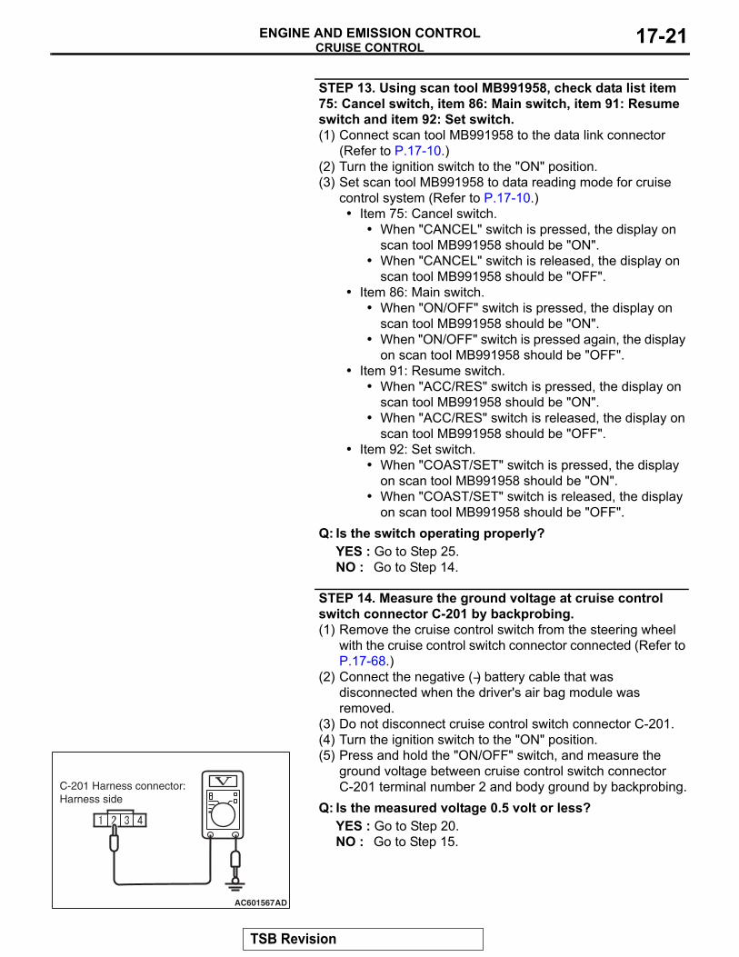
STEP 14. Measure the ground voltage at cruise control switch connector C-201 by backprobing.(1) Remove the cruise control switch from the steering wheel
with the cruise control switch connector connected (Refer to P.17-68.)
(2) Connect the negative (−) battery cable that was disconnected when the driver's air bag module was removed.
(3) Do not disconnect cruise control switch connector C-201.(4) Turn the ignition switch to the "ON" position.(5) Press and hold the "ON/OFF" switch, and measure the
ground voltage between cruise control switch connector C-201 terminal number 2 and body ground by backprobing.
Q: Is the measured voltage 0.5 volt or less?YES : Go to Step 20.NO : Go to Step 15.
AC601567AD
C-201 Harness connector:Harness side
TSB Revision
CRUISE CONTROLENGINE AND EMISSION CONTROL17-22
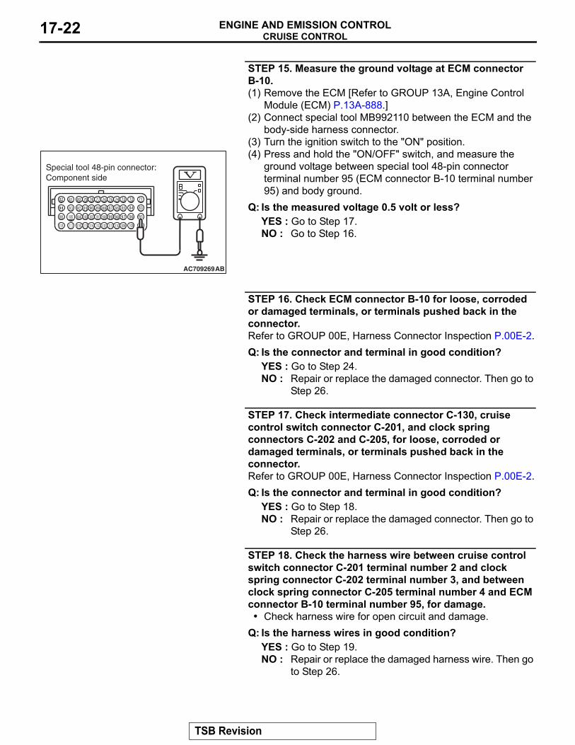
STEP 15. Measure the ground voltage at ECM connector B-10.(1) Remove the ECM [Refer to GROUP 13A, Engine Control
Module (ECM) P.13A-888.](2) Connect special tool MB992110 between the ECM and the
body-side harness connector.(3) Turn the ignition switch to the "ON" position.(4) Press and hold the "ON/OFF" switch, and measure the
ground voltage between special tool 48-pin connector terminal number 95 (ECM connector B-10 terminal number 95) and body ground.
Q: Is the measured voltage 0.5 volt or less?YES : Go to Step 17.NO : Go to Step 16.
STEP 16. Check ECM connector B-10 for loose, corroded or damaged terminals, or terminals pushed back in the connector.Refer to GROUP 00E, Harness Connector Inspection P.00E-2.Q: Is the connector and terminal in good condition?
YES : Go to Step 24.NO : Repair or replace the damaged connector. Then go to
Step 26.
STEP 17. Check intermediate connector C-130, cruise control switch connector C-201, and clock spring connectors C-202 and C-205, for loose, corroded or damaged terminals, or terminals pushed back in the connector.Refer to GROUP 00E, Harness Connector Inspection P.00E-2.Q: Is the connector and terminal in good condition?
YES : Go to Step 18.NO : Repair or replace the damaged connector. Then go to
Step 26.
STEP 18. Check the harness wire between cruise control switch connector C-201 terminal number 2 and clock spring connector C-202 terminal number 3, and between clock spring connector C-205 terminal number 4 and ECM connector B-10 terminal number 95, for damage.• Check harness wire for open circuit and damage.
Q: Is the harness wires in good condition?YES : Go to Step 19.NO : Repair or replace the damaged harness wire. Then go
to Step 26.
AC709269AB
Special tool 48-pin connector:Component side
TSB Revision
CRUISE CONTROLENGINE AND EMISSION CONTROL 17-23
STEP 19. Check the clock spring.Refer to GROUP 52B, Driver’s Air Bag Module Inspection P.52B-419.Q: Is the clock spring in good condition?
YES : Go to Step 24.NO : Replace the clock spring (Refer to GROUP 52B,
Driver’s Air Bag Module and Clock Spring P.52B-413). Then go to Step 26.
STEP 20. Check ECM connector B-10, intermediate connector C-130, cruise control switch connector C-201, and clock spring connectors C-202 and C-205, for loose, corroded or damaged terminals, or terminals pushed back in the connector.Refer to GROUP 00E, Harness Connector Inspection P.00E-2.Q: Is the connector and terminal in good condition?
YES : Go to Step 21.NO : Repair or replace the damaged connector. Then go to
Step 26.
STEP 21. Check the harness wire between cruise control switch connector C-201 terminal number 2 and clock spring connector C-202 terminal number 3, and between clock spring connector C-205 terminal number 4 and ECM connector B-10 terminal number 95, for damage.• Check harness wire for short circuit and damage.
Q: Is the harness wires in good condition?YES : Go to Step 22.NO : Repair or replace the damaged harness wire. Then go
to Step 26.
STEP 22. Check the clock spring.Refer to GROUP 52B, Driver’s Air Bag Module Inspection P.52B-419.Q: Is the clock spring in good condition?
YES : Go to Step 23.NO : Replace the clock spring (Refer to GROUP 52B,
Driver’s Air Bag Module and Clock Spring P.52B-413.) Then go to Step 26.
STEP 23. Check the cruise control switch.Refer to P.17-67.Q: Is the cruise control switch operating properly?
YES : Go to Step 24.NO : Replace the cruise control switch (Refer to P.17-68.)
Then go to Step 26.
TSB Revision
CRUISE CONTROLENGINE AND EMISSION CONTROL17-24
STEP 24. Using scan tool MB991958, check data list item 75: Cancel switch, item 86: Main switch, item 91: Resume switch and item 92: Set switch.(1) Connect scan tool MB991958 to the data link connector
(Refer to P.17-10.)(2) Turn the ignition switch to the "ON" position.(3) Set scan tool MB991958 to data reading mode for cruise
control system (Refer to P.17-10.)• Item 75: Cancel switch.
• When "CANCEL" switch is pressed, the display on scan tool MB991958 should be "ON".
• When "CANCEL" switch is released, the display on scan tool MB991958 should be "OFF".
• Item 86: Main switch.• When "ON/OFF" switch is pressed, the display on
scan tool MB991958 should be "ON".• When "ON/OFF" switch is pressed again, the display
on scan tool MB991958 should be "OFF".• Item 91: Resume switch.
• When "ACC/RES" switch is pressed, the display on scan tool MB991958 should be "ON".
• When "ACC/RES" switch is released, the display on scan tool MB991958 should be "OFF".
• Item 92: Set switch.• When "COAST/SET" switch is pressed, the display
on scan tool MB991958 should be "ON".• When "COAST/SET" switch is released, the display
on scan tool MB991958 should be "OFF".Q: Is the switch operating properly?
YES : Go to Step 25.NO : Replace the ECM [Refer to GROUP 13A, Engine
Control Module (ECM) P.13A-888.] When the ECM is replaced, register the encrypted code (Refer to GROUP 42C, Diagnosis − ID Code Registration Judgment Table P.42C-9.) Then go to Step 26.
TSB Revision
CRUISE CONTROLENGINE AND EMISSION CONTROL 17-25
STEP 25. Read the cruise control system DTC.(1) Disconnect the negative (−) battery terminal, to erase the
DTC of the cruise control system.(2) Connect the negative (−) battery terminal.(3) Turn the ignition switch to the "ON" position, and press the
"ON/OFF" switch to turn the cruise control system to ON (turn on the "CRUISE" indicator light.)
(4) After turning the cruise control system to ON, when 2 minutes or more has elapsed without operating the cruise control switches, read the DTC of the cruise control system (Refer to P.17-10.)
Q: Is DTC 15 set?YES : Replace the ECM [Refer to GROUP 13A, Engine
Control Module (ECM) P.13A-888.] When the ECM is replaced, register the encrypted code (Refer to GROUP 42C, Diagnosis − ID Code Registration Judgment Table P.42C-9.) Then go to Step 26.
NO : It can be assumed that this malfunction is intermittent (Refer to GROUP 00, How to Use Troubleshooting/Inspection Service Points − How to Cope with Intermittent Malfunction P.00-15.)
STEP 26. Using scan tool MB991958, check data list item 75: Cancel switch, item 86: Main switch, item 91: Resume switch and item 92: Set switch.(1) Connect scan tool MB991958 to the data link connector
(Refer to P.17-10.)(2) Turn the ignition switch to the "ON" position.(3) Set scan tool MB991958 to data reading mode for cruise
control system (Refer to P.17-10.)• Item 75: Cancel switch.
• When "CANCEL" switch is pressed, the display on scan tool MB991958 should be "ON".
• When "CANCEL" switch is released, the display on scan tool MB991958 should be "OFF".
• Item 86: Main switch.• When "ON/OFF" switch is pressed, the display on
scan tool MB991958 should be "ON".• When "ON/OFF" switch is pressed again, the display
on scan tool MB991958 should be "OFF".• Item 91: Resume switch.
• When "ACC/RES" switch is pressed, the display on scan tool MB991958 should be "ON".
• When "ACC/RES" switch is released, the display on scan tool MB991958 should be "OFF".
• Item 92: Set switch.• When "COAST/SET" switch is pressed, the display
on scan tool MB991958 should be "ON".• When "COAST/SET" switch is released, the display
on scan tool MB991958 should be "OFF".
TSB Revision
CRUISE CONTROLENGINE AND EMISSION CONTROL17-26
Q: Is the switch operating properly?YES : Go to Step 27.NO : Return to Step 2.
STEP 27. Read the cruise control system DTC.(1) Disconnect the negative (−) battery terminal, to erase the
DTC of the cruise control system.(2) Connect the negative (−) battery terminal.(3) Turn the ignition switch to the "ON" position, and press the
"ON/OFF" switch to turn the cruise control system to ON (turn on the "CRUISE" indicator light.)
(4) After turning the cruise control system to ON, when 2 minutes or more has elapsed without operating the cruise control switches, read the DTC of the cruise control system (Refer to P.17-10.)
Q: Is DTC 15 set?YES : Return to Step 1.NO : The procedure is complete.
TSB Revision
CRUISE CONTROLENGINE AND EMISSION CONTROL 17-27
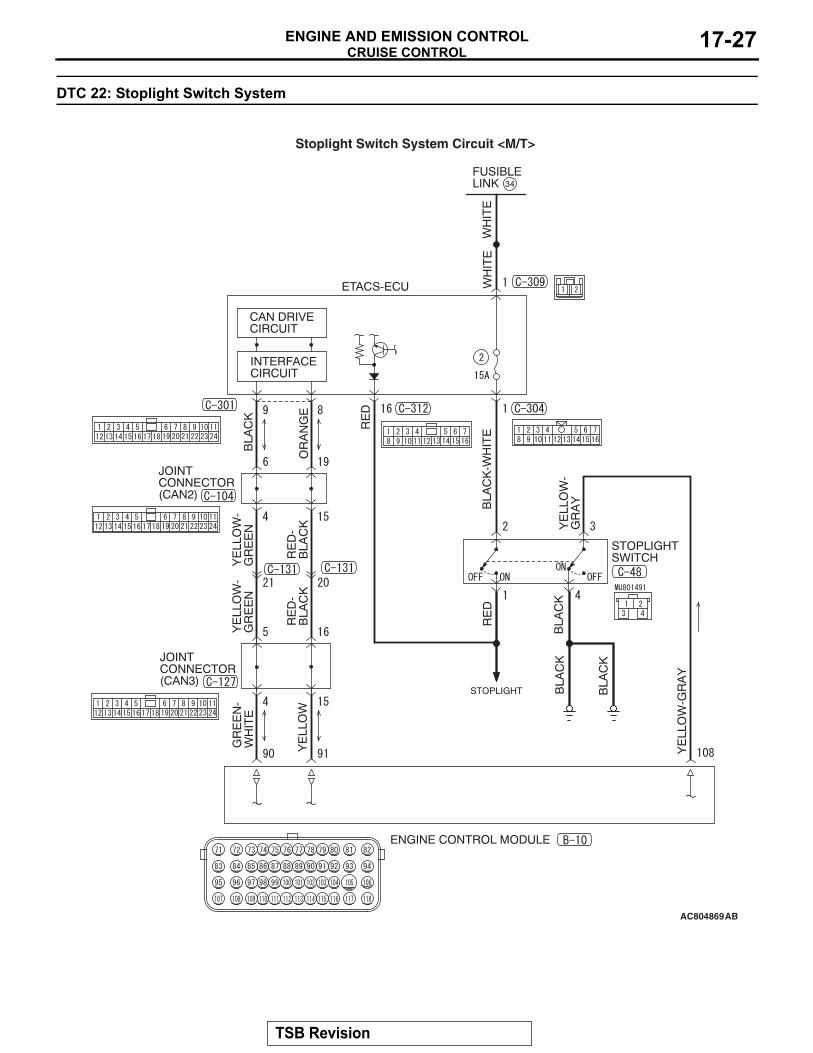
DTC 22: Stoplight Switch System
AC804869AB
Stoplight Switch System Circuit <M/T>
TSB Revision
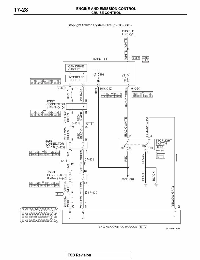
CRUISE CONTROLENGINE AND EMISSION CONTROL17-28
AC804870 AB
Stoplight Switch System Circuit <TC-SST>
TSB Revision
CRUISE CONTROLENGINE AND EMISSION CONTROL 17-29
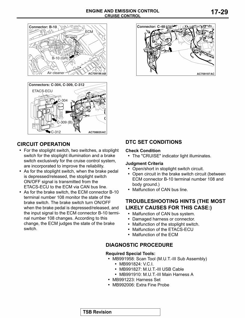
.
CIRCUIT OPERATION• For the stoplight switch, two switches, a stoplight
switch for the stoplight illumination and a brake switch exclusively for the cruise control system, are incorporated to improve the reliability.
• As for the stoplight switch, when the brake pedal is depressed/released, the stoplight switch ON/OFF signal is transmitted from the ETACS-ECU to the ECM via CAN bus line.
• As for the brake switch, the ECM connector B-10 terminal number 108 monitor the state of the brake switch. The brake switch turn ON/OFF when the brake pedal is depressed/released, and the input signal to the ECM connector B-10 termi-nal number 108 changes. According to this change, the ECM judges the state of the brake switch.
.
DTC SET CONDITIONSCheck Condition
• The "CRUISE" indicator light illuminates.
Judgment Criteria• Open/short in stoplight switch circuit.• Open circuit in the brake switch circuit (between
ECM connector B-10 terminal number 108 and body ground.)
• Malfunction of CAN bus line..
TROUBLESHOOTING HINTS (THE MOST LIKELY CAUSES FOR THIS CASE:)
• Malfunction of CAN bus system.• Damaged harness or connector.• Malfunction of the stoplight switch.• Malfunction of the ETACS-ECU• Malfunction of the ECM
DIAGNOSTIC PROCEDURERequired Special Tools:• MB991958: Scan Tool (M.U.T.-III Sub Assembly)
• MB991824: V.C.I.• MB991827: M.U.T.-III USB Cable• MB991910: M.U.T.-III Main Harness A
• MB991223: Harness Set• MB992006: Extra Fine Probe
AC709196 AB
B-10 (GR)
Connector: B-10ECM
Air cleaner AC709197
Connector: C-48
AC
AC708835AC
ETACS-ECU
Connectors: C-304, C-309, C-312
C-309 (B)
C-304
C-312
TSB Revision
CRUISE CONTROLENGINE AND EMISSION CONTROL17-30
CAUTIONIf there is any problem in the CAN bus lines, an incorrect diagnostic trouble code (DTC) may be set. Prior to this diagnosis, diagnose the CAN bus lines (Refer to GROUP 54C, Trouble code diagnosis P.54C-9.)
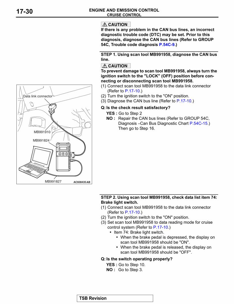
STEP 1. Using scan tool MB991958, diagnose the CAN bus line.
CAUTIONTo prevent damage to scan tool MB991958, always turn the ignition switch to the "LOCK" (OFF) position before con-necting or disconnecting scan tool MB991958.(1) Connect scan tool MB991958 to the data link connector
(Refer to P.17-10.)(2) Turn the ignition switch to the "ON" position.(3) Diagnose the CAN bus line (Refer to P.17-10.)Q: Is the check result satisfactory?
YES : Go to Step 2NO : Repair the CAN bus lines (Refer to GROUP 54C,
Diagnosis − Can Bus Diagnostic Chart P.54C-15.) Then go to Step 16.
STEP 2. Using scan tool MB991958, check data list item 74: Brake light switch.(1) Connect scan tool MB991958 to the data link connector
(Refer to P.17-10.)(2) Turn the ignition switch to the "ON" position.(3) Set scan tool MB991958 to data reading mode for cruise
control system (Refer to P.17-10.)• Item 74: Brake light switch.
• When the brake pedal is depressed, the display on scan tool MB991958 should be "ON".
• When the brake pedal is released, the display on scan tool MB991958 should be "OFF".
Q: Is the switch operating properly?YES : Go to Step 10.NO : Go to Step 3.
AC608435
Data link connector
MB991827
MB991824
MB991910
AB
TSB Revision
CRUISE CONTROLENGINE AND EMISSION CONTROL 17-31
STEP 3. Using scan tool MB991958, check ETACS system data list item 290: Brake light switch.(1) Connect scan tool MB991958 to the data link connector
(Refer to P.17-10.)(2) Turn the ignition switch to the "ON" position.(3) Set scan tool MB991958 to data reading mode for ETACS
system (Refer to GROUP 54A, ETACS, Troubleshooting − Data List Reference Table P.54A-694.)
• Item 290: Brake light switch.• When the brake pedal is depressed, the display on
scan tool MB991958 should be "ON".• When the brake pedal is released, the display on
scan tool MB991958 should be "OFF".Q: Is the switch operating properly?
YES : Replace the ECM [Refer to GROUP 13A, Engine Control Module (ECM) P.13A-888.] When the ECM is replaced, register the encrypted code (Refer to GROUP 42C, Diagnosis − ID Code Registration Judgment Table P.42C-9.) Then go to Step 16.
NO : Go to Step 4.
STEP 4. Check stoplight switch connector C-48, and ETACS-ECU connector C-304 and C-312, for loose, corroded or damaged terminals, or terminals pushed back in the connector.Refer to GROUP 00E, Harness Connector Inspection P.00E-2.Q: Is the connector and terminal in good condition?
YES : Go to Step 5.NO : Repair or replace the damaged connector. Then go to
Step 16.
STEP 5. Check the harness wire between ETACS-ECU connector C-304 terminal number 1 and stoplight switch connector C-48 terminal number 2, and between stoplight switch connector C-48 terminal number 1 and ETACS-ECU connector C-312 terminal number 16, for damage.• Check harness wire for open/short circuit and damage.
Q: Is the harness wire in good condition?YES : Go to Step 6.NO : Repair or replace the damaged harness wire. Then go
to Step 16.
TSB Revision
CRUISE CONTROLENGINE AND EMISSION CONTROL17-32
STEP 6. Check fuse number 2 at the ETACS-ECU.Q: Is the fuse in good condition?
YES : Go to Step 7.NO : Check the stoplight system harness and replace the
fuse. Then go to Step 16.
STEP 7. Check the stoplight switch.Refer to GROUP 35A, Brake Pedal, Inspection − Stoplight Switch Check P.35A-25.Q: Is the stoplight switch operating properly?
YES : Go to Step 8.NO : Replace the stoplight switch (Refer to GROUP 35A,
Brake Pedal P.35A-24.) Then go to Step 16.
STEP 8. Using scan tool MB991958, check ETACS system data list item 290: Brake light switch.(1) Connect scan tool MB991958 to the data link connector
(Refer to P.17-10).(2) Turn the ignition switch to the "ON" position.(3) Set scan tool MB991958 to data reading mode for ETACS
system (Refer to GROUP 54A, ETACS − Data List Reference Table P.54A-694.)
• Item 290: Brake light switch.• When the brake pedal is depressed, the display on
scan tool MB991958 should be "ON".• When the brake pedal is released, the display on
scan tool MB991958 should be "OFF".Q: Is the switch operating properly?
YES : Go to Step 9.NO : Replace the ETACS-ECU (Refer to GROUP 54A,
ETACS, ETACS-ECU P.54A-742.) Then go to Step 16.
AC709274 AB
ETACS-ECU Fuse number 2(Housing color: Blue)
Brake pedal
TSB Revision
CRUISE CONTROLENGINE AND EMISSION CONTROL 17-33
STEP 9. Using scan tool MB991958, check data list item 74: Brake light switch.(1) Connect scan tool MB991958 to the data link connector
(Refer to P.17-10.)(2) Turn the ignition switch to the "ON" position.(3) Set scan tool MB991958 to data reading mode for cruise
control system (Refer to P.17-10.)• Item 74: Brake light switch.
• When the brake pedal is depressed, the display on scan tool MB991958 should be "ON."
• When the brake pedal is released, the display on scan tool MB991958 should be "OFF."
Q: Is the switch operating properly?YES : Go to Step 10.NO : Replace the ECM [Refer to GROUP 13A, Engine
Control Module (ECM) P.13A-888.] When the ECM is replaced, register the encrypted code (Refer to GROUP 42C, Diagnosis − ID Code Registration Judgment Table P.42C-9.) Then go to Step 16.
STEP 10. Using scan tool MB991958, check data list item 89: Normally closed brake switch.(1) Connect scan tool MB991958 to the data link connector
(Refer to P.17-10).(2) Turn the ignition switch to the "ON" position.(3) Set scan tool MB991958 to data reading mode for cruise
control system (Refer to P.17-10.)• Item 89: Normally closed brake switch.
• When the brake pedal is depressed, the display on scan tool MB991958 should be "ON".
• When the brake pedal is released, the display on scan tool MB991958 should be "OFF".
Q: Is the switch operating properly?YES : Go to Step 15.NO : Go to Step 11.
STEP 11. Check ECM connector B-10 and stoplight switch connector C-48, for loose, corroded or damaged terminals, or terminals pushed back in the connector.Refer to GROUP 00E, Harness Connector Inspection P.00E-2.Q: Is the connector and terminal in good condition?
YES : Go to Step 12.NO : Repair or replace the damaged connector. Then go to
Step 16.
TSB Revision
CRUISE CONTROLENGINE AND EMISSION CONTROL17-34
STEP 12. Check the harness wire between ECM connector B-109 terminal number 108 and stoplight switch connector C-32 terminal number 3, and between stoplight switch connector C-32 terminal number 4 and body ground, for damage.• Check harness wire for open/short circuit and damage.
Q: Is the harness wire in good condition?YES : Go to Step 13.NO : Repair or replace the damaged harness wire. Then go
to Step 16.
STEP 13. Check the stoplight switch.Refer to GROUP 35A, Brake Pedal, Inspection − Stoplight Switch Check P.35A-25.Q: Is the stoplight switch operating properly?
YES : Go to Step 14.NO : Replace the stoplight switch (Refer to GROUP 35A,
Brake Pedal P.35A-24.) Then go to Step 16.
STEP 14. Using scan tool MB991958, check data list item 89: Normally closed brake switch.(1) Connect scan tool MB991958 to the data link connector
(Refer to P.17-10.)(2) Turn the ignition switch to the "ON" position.(3) Set scan tool MB991958 to data reading mode for cruise
control system (Refer to P.17-10.)• Item 89: Normally closed brake switch.
• When the brake pedal is depressed, the display on scan tool MB991958 should be "ON."
• When the brake pedal is released, the display on scan tool MB991958 should be "OFF."
Q: Is the switch operating properly?YES : Go to Step 15.NO : Replace the ECM [Refer to GROUP 13A, Engine
Control Module (ECM) P.13A-888.] When the ECM is replaced, register the encrypted code (Refer to GROUP 42C, Diagnosis − ID Code Registration Judgment Table P.42C-9.) Then go to Step 16.
AC709275AB
ETACS-ECU
TSB Revision
CRUISE CONTROLENGINE AND EMISSION CONTROL 17-35
STEP 15. Read the cruise control system DTC.(1) Disconnect the negative (−) battery terminal, to erase the
DTC of the cruise control system.(2) Connect the negative (−) battery cable.(3) Turn the ignition switch to the "ON" position, and press the
"ON/OFF" switch to turn the cruise control system to ON (turn on the "CRUISE" indicator light.)
(4) With the cruise control switches not operated, depress the brake pedal for several seconds, and then read the DTC of the cruise control system (Refer to P.17-10.)
Q: Is DTC 22 set?YES : Replace the ECM [Refer to GROUP 13A, Engine
Control Module (ECM) P.13A-888.] When the ECM is replaced, register the encrypted code (Refer to GROUP 42C, Diagnosis − ID Code Registration Judgment Table P.42C-9.) Then go to Step 16.
NO : It can be assumed that this malfunction is intermittent (Refer to GROUP 00, How to Use Troubleshooting/Inspection Service Points − How to Cope with Intermittent Malfunction P.00-15.)
STEP 16. Using scan tool MB991958, check data list item 74: Brake light switch and item 89: Normally closed brake switch.(1) Connect scan tool MB991958 to the data link connector
(Refer to P.17-10.)(2) Turn the ignition switch to the "ON" position.(3) Set scan tool MB991958 to data reading mode for cruise
control system (Refer to P.17-10.)• Item 74: Brake light switch.
• When the brake pedal is depressed, the display on scan tool MB991958 should be "ON."
• When the brake pedal is released, the display on scan tool MB991958 should be "OFF."
• Item 89: Normally closed brake switch.• When the brake pedal is depressed, the display on
scan tool MB991958 should be "ON."• When the brake pedal is released, the display on
scan tool MB991958 should be "OFF."Q: Is the switch operating properly?
YES : Go to Step 17.NO : Return to Step 2.
TSB Revision
CRUISE CONTROLENGINE AND EMISSION CONTROL17-36
STEP 17. Read the cruise control system DTC.(1) Disconnect the negative (−) battery terminal, to erase the
DTC of the cruise control system.(2) Connect the negative (−) battery cable.(3) Turn the ignition switch to the "ON" position, and press the
"ON/OFF" switch to turn the cruise control system to ON (turn on the "CRUISE" indicator light.)
(4) With the cruise control switches not operated, depress the brake pedal for several seconds, and then read the DTC of the cruise control system (Refer to P.17-10.)
Q: Is DTC 22 set?YES : Return to Step 1.NO : The procedure is complete.
DTC 23: ECM and Its Related Components
.
DTC SET CONDITIONSThis DTC is set when there is an failure in the ECM and its related components..
TROUBLESHOOTING HINTS (THE MOST LIKELY CAUSES FOR THIS CASE:)
• Malfunction of the MFI system.• Malfunction of the ECM.
DIAGNOSTIC PROCEDURERequired Special Tools:• MB991958: Scan Tool (M.U.T.-III Sub Assembly)
• MB991824: V.C.I.• MB991827: M.U.T.-III USB Cable• MB991910: M.U.T.-III Main Harness A
TSB Revision
CRUISE CONTROLENGINE AND EMISSION CONTROL 17-37
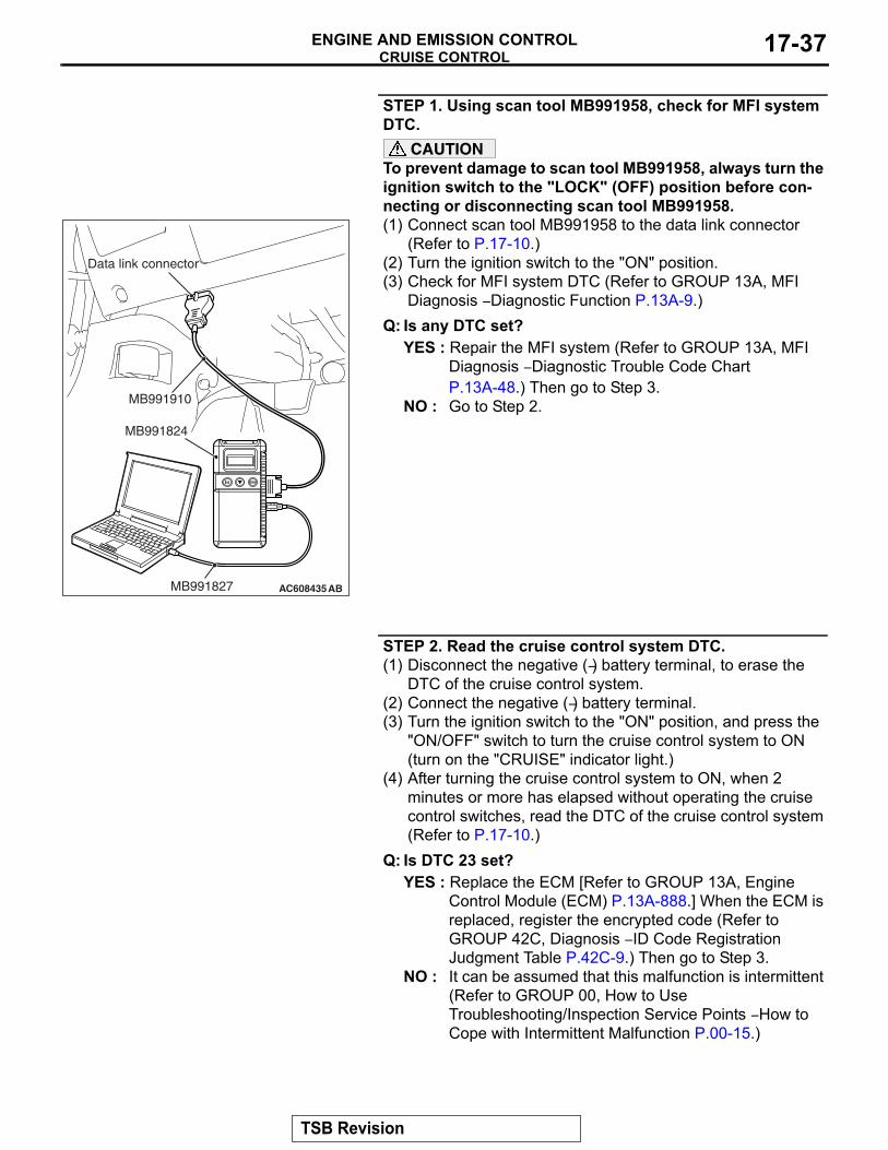
STEP 1. Using scan tool MB991958, check for MFI system DTC.
CAUTIONTo prevent damage to scan tool MB991958, always turn the ignition switch to the "LOCK" (OFF) position before con-necting or disconnecting scan tool MB991958.(1) Connect scan tool MB991958 to the data link connector
(Refer to P.17-10.)(2) Turn the ignition switch to the "ON" position.(3) Check for MFI system DTC (Refer to GROUP 13A, MFI
Diagnosis − Diagnostic Function P.13A-9.)Q: Is any DTC set?
YES : Repair the MFI system (Refer to GROUP 13A, MFI Diagnosis − Diagnostic Trouble Code Chart P.13A-48.) Then go to Step 3.
NO : Go to Step 2.
STEP 2. Read the cruise control system DTC.(1) Disconnect the negative (−) battery terminal, to erase the
DTC of the cruise control system.(2) Connect the negative (−) battery terminal.(3) Turn the ignition switch to the "ON" position, and press the
"ON/OFF" switch to turn the cruise control system to ON (turn on the "CRUISE" indicator light.)
(4) After turning the cruise control system to ON, when 2 minutes or more has elapsed without operating the cruise control switches, read the DTC of the cruise control system (Refer to P.17-10.)
Q: Is DTC 23 set?YES : Replace the ECM [Refer to GROUP 13A, Engine
Control Module (ECM) P.13A-888.] When the ECM is replaced, register the encrypted code (Refer to GROUP 42C, Diagnosis − ID Code Registration Judgment Table P.42C-9.) Then go to Step 3.
NO : It can be assumed that this malfunction is intermittent (Refer to GROUP 00, How to Use Troubleshooting/Inspection Service Points − How to Cope with Intermittent Malfunction P.00-15.)
AC608435
Data link connector
MB991827
MB991824
MB991910
AB
TSB Revision
CRUISE CONTROLENGINE AND EMISSION CONTROL17-38
STEP 3. Read the cruise control system DTC.(1) Disconnect the negative (−) battery terminal, to erase the
DTC of the cruise control system.(2) Connect the negative (−) battery terminal.(3) Turn the ignition switch to the "ON" position, and press the
"ON/OFF" switch to turn the cruise control system to ON (turn on the "CRUISE" indicator light.)
(4) After turning the cruise control system to ON, when 2 minutes or more has elapsed without operating the cruise control switches, read the DTC of the cruise control system (Refer to P.17-10.)
Q: Is DTC 23 set?YES : Return to Step 1.NO : The procedure is complete.
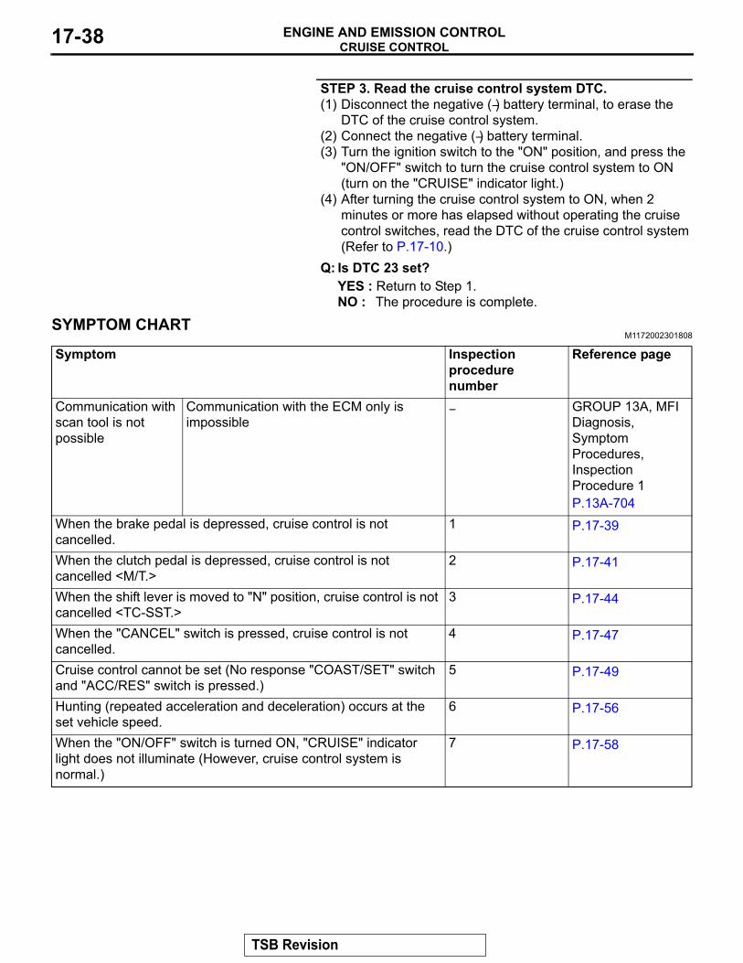
SYMPTOM CHARTM1172002301808
Symptom Inspection procedure number
Reference page
Communication with scan tool is not possible
Communication with the ECM only is impossible
− GROUP 13A, MFI Diagnosis, Symptom Procedures, Inspection Procedure 1 P.13A-704
When the brake pedal is depressed, cruise control is not cancelled.
1 P.17-39
When the clutch pedal is depressed, cruise control is not cancelled <M/T.>
2 P.17-41
When the shift lever is moved to "N" position, cruise control is not cancelled <TC-SST.>
3 P.17-44
When the "CANCEL" switch is pressed, cruise control is not cancelled.
4 P.17-47
Cruise control cannot be set (No response "COAST/SET" switch and "ACC/RES" switch is pressed.)
5 P.17-49
Hunting (repeated acceleration and deceleration) occurs at the set vehicle speed.
6 P.17-56
When the "ON/OFF" switch is turned ON, "CRUISE" indicator light does not illuminate (However, cruise control system is normal.)
7 P.17-58
TSB Revision
CRUISE CONTROLENGINE AND EMISSION CONTROL 17-39
SYMPTOM PROCEDURES
Inspection Procedure 1: When the Brake Pedal is Depressed, Cruise Control is not Cancelled.
.
COMMENT• Malfunction of CAN bus line.• The stoplight switch circuit is suspected.
.
TROUBLESHOOTING HINTS (THE MOST LIKELY CAUSES FOR THIS CASE:)
• Malfunction of CAN bus system.• Damaged harness or connector.• Malfunction of the stoplight switch.• Malfunction of the ETACS-ECU.• Malfunction of the ECM.
DIAGNOSTIC PROCEDURERequired Special Tools:• MB991958: Scan Tool (M.U.T.-III Sub Assembly)
• MB991824: V.C.I.• MB991827: M.U.T.-III USB Cable• MB991910: M.U.T.-III Main Harness A
CAUTIONIf there is any problem in the CAN bus lines, an incorrect diagnostic trouble code (DTC) may be set. Prior to this diagnosis, diagnose the CAN bus lines (Refer to GROUP 54C, Trouble code diagnosis P.54C-9.)
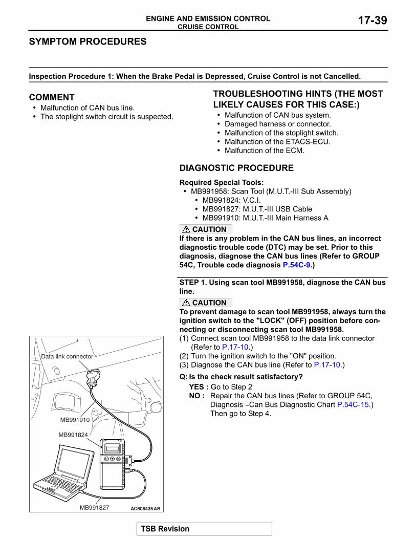
STEP 1. Using scan tool MB991958, diagnose the CAN bus line.
CAUTIONTo prevent damage to scan tool MB991958, always turn the ignition switch to the "LOCK" (OFF) position before con-necting or disconnecting scan tool MB991958.(1) Connect scan tool MB991958 to the data link connector
(Refer to P.17-10.)(2) Turn the ignition switch to the "ON" position.(3) Diagnose the CAN bus line (Refer to P.17-10.)Q: Is the check result satisfactory?
YES : Go to Step 2NO : Repair the CAN bus lines (Refer to GROUP 54C,
Diagnosis − Can Bus Diagnostic Chart P.54C-15.) Then go to Step 4.
AC608435
Data link connector
MB991827
MB991824
MB991910
AB
TSB Revision
CRUISE CONTROLENGINE AND EMISSION CONTROL17-40
STEP 2. Using scan tool MB991958, check data list item 74: Brake light switch and item 89: Normally closed brake switch.(1) Connect scan tool MB991958 to the data link connector
(Refer to P.17-10.)(2) Turn the ignition switch to the "ON" position.(3) Set scan tool MB991958 to data reading mode for cruise
control system (Refer to P.17-10.)• Item 74: Brake light switch.
• When the brake pedal is depressed, the display on scan tool MB991958 should be "ON".
• When the brake pedal is released, the display on scan tool MB991958 should be "OFF".
• Item 89: Normally closed brake switch.• When the brake pedal is depressed, the display on
scan tool MB991958 should be "ON".• When the brake pedal is released, the display on
scan tool MB991958 should be "OFF".Q: Is the switch operating properly?
YES : Go to Step 3NO : Repair the stoplight switch system (Refer to P.17-27,
Diagnostic Trouble Code Procedures − DTC 22: Stoplight Switch System.) Then go to Step 4.
STEP 3. Check the symptoms.Q: When the brake pedal is depressed, is the cruise control
cancelled?YES : It can be assumed that this malfunction is intermittent
(Refer to GROUP 00, How to Use Troubleshooting/Inspection Service Points − How to Cope with Intermittent Malfunction P.00-15.)
NO : Replace the ECM [Refer to GROUP 13A, Engine Control Module (ECM) P.13A-888.] When the ECM is replaced, register the encrypted code (Refer to GROUP 42C, Diagnosis − ID Code Registration Judgment Table P.42C-9.) Then go to Step 4.
STEP 4. Check the symptoms.Q: When the brake pedal is depressed, is the cruise control
cancelled?YES : The procedure is complete.NO : Return to Step 1.
TSB Revision
CRUISE CONTROLENGINE AND EMISSION CONTROL 17-41
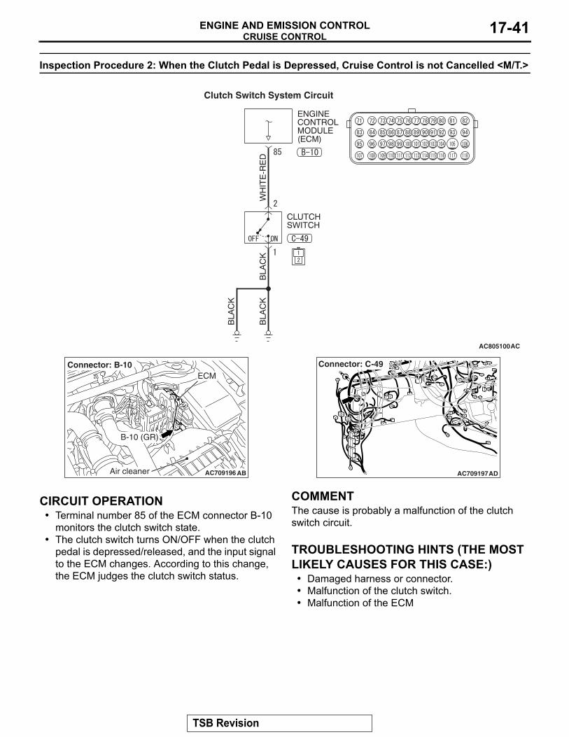
Inspection Procedure 2: When the Clutch Pedal is Depressed, Cruise Control is not Cancelled <M/T.>
.
CIRCUIT OPERATION• Terminal number 85 of the ECM connector B-10
monitors the clutch switch state.• The clutch switch turns ON/OFF when the clutch
pedal is depressed/released, and the input signal to the ECM changes. According to this change, the ECM judges the clutch switch status.
.
COMMENTThe cause is probably a malfunction of the clutch switch circuit..
TROUBLESHOOTING HINTS (THE MOST LIKELY CAUSES FOR THIS CASE:)
• Damaged harness or connector.• Malfunction of the clutch switch.• Malfunction of the ECM
AC805100AC
Clutch Switch System Circuit
AC709196 AB
B-10 (GR)
Connector: B-10ECM
Air cleaner AC709197
Connector: C-49
AD
TSB Revision
CRUISE CONTROLENGINE AND EMISSION CONTROL17-42
DIAGNOSTIC PROCEDURERequired Special Tools:• MB991958: Scan Tool (M.U.T.-III Sub Assembly)
• MB991824: V.C.I.• MB991827: M.U.T.-III USB Cable• MB991910: M.U.T.-III Main Harness A
• MB991223: Harness Set• MB992006: Extra Fine Probe
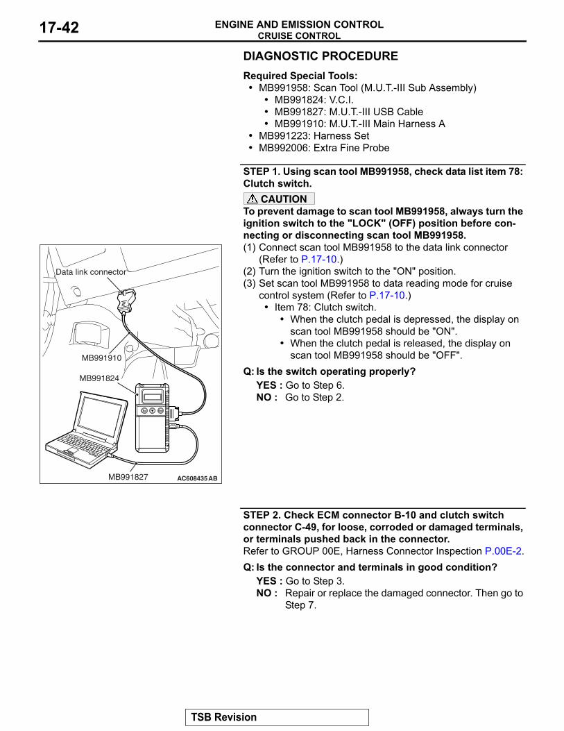
STEP 1. Using scan tool MB991958, check data list item 78: Clutch switch.
CAUTIONTo prevent damage to scan tool MB991958, always turn the ignition switch to the "LOCK" (OFF) position before con-necting or disconnecting scan tool MB991958.(1) Connect scan tool MB991958 to the data link connector
(Refer to P.17-10.)(2) Turn the ignition switch to the "ON" position.(3) Set scan tool MB991958 to data reading mode for cruise
control system (Refer to P.17-10.)• Item 78: Clutch switch.
• When the clutch pedal is depressed, the display on scan tool MB991958 should be "ON".
• When the clutch pedal is released, the display on scan tool MB991958 should be "OFF".
Q: Is the switch operating properly?YES : Go to Step 6.NO : Go to Step 2.
STEP 2. Check ECM connector B-10 and clutch switch connector C-49, for loose, corroded or damaged terminals, or terminals pushed back in the connector.Refer to GROUP 00E, Harness Connector Inspection P.00E-2.Q: Is the connector and terminals in good condition?
YES : Go to Step 3.NO : Repair or replace the damaged connector. Then go to
Step 7.
AC608435
Data link connector
MB991827
MB991824
MB991910
AB
TSB Revision
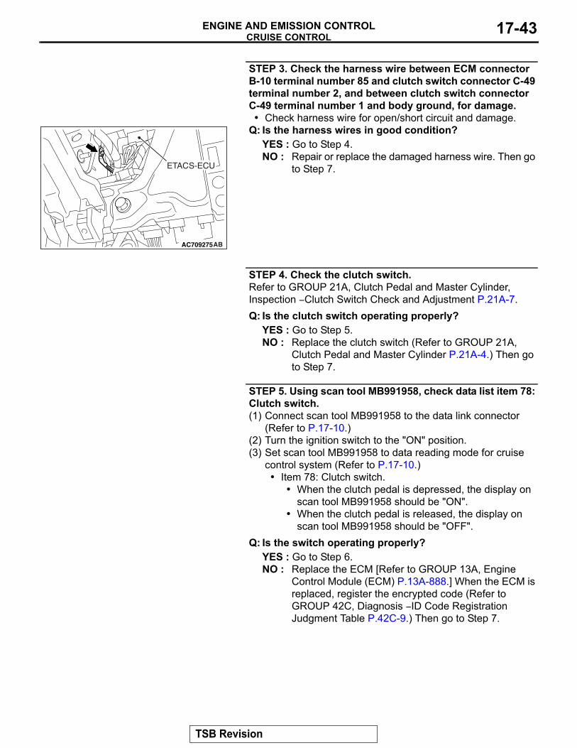
CRUISE CONTROLENGINE AND EMISSION CONTROL 17-43
STEP 3. Check the harness wire between ECM connector B-10 terminal number 85 and clutch switch connector C-49 terminal number 2, and between clutch switch connector C-49 terminal number 1 and body ground, for damage.• Check harness wire for open/short circuit and damage.
Q: Is the harness wires in good condition?YES : Go to Step 4.NO : Repair or replace the damaged harness wire. Then go
to Step 7.
STEP 4. Check the clutch switch.Refer to GROUP 21A, Clutch Pedal and Master Cylinder, Inspection − Clutch Switch Check and Adjustment P.21A-7.Q: Is the clutch switch operating properly?
YES : Go to Step 5.NO : Replace the clutch switch (Refer to GROUP 21A,
Clutch Pedal and Master Cylinder P.21A-4.) Then go to Step 7.
STEP 5. Using scan tool MB991958, check data list item 78: Clutch switch.(1) Connect scan tool MB991958 to the data link connector
(Refer to P.17-10.)(2) Turn the ignition switch to the "ON" position.(3) Set scan tool MB991958 to data reading mode for cruise
control system (Refer to P.17-10.)• Item 78: Clutch switch.
• When the clutch pedal is depressed, the display on scan tool MB991958 should be "ON".
• When the clutch pedal is released, the display on scan tool MB991958 should be "OFF".
Q: Is the switch operating properly?YES : Go to Step 6.NO : Replace the ECM [Refer to GROUP 13A, Engine
Control Module (ECM) P.13A-888.] When the ECM is replaced, register the encrypted code (Refer to GROUP 42C, Diagnosis − ID Code Registration Judgment Table P.42C-9.) Then go to Step 7.
AC709275AB
ETACS-ECU
TSB Revision
CRUISE CONTROLENGINE AND EMISSION CONTROL17-44
STEP 6. Check the symptomsQ: When the clutch pedal is depressed, is the cruise
control cancelled?YES : It can be assumed that this malfunction is intermittent
(Refer to GROUP 00, How to Use Troubleshooting/Inspection Service Points - How to Cope with Intermittent Malfunction P.00-15.)
NO : Replace the ECM [Refer to GROUP 13A, Engine Control Module (ECM) P.13A-888.] When the ECM is replaced, register the encrypted code (Refer to GROUP 42C, Diagnosis − ID Code Registration Judgment Table P.42C-9.) Then go to Step 7.
STEP 7. Check the symptoms.Q: When the clutch pedal is depressed, is the cruise
control cancelled?YES : The procedure is complete.NO : Return to Step 1.
Inspection Procedure 3: When the Shift Lever is Moved to "N" Position, Cruise Control is not Cancelled <TC-SST.>
.
CIRCUIT OPERATIONWhen the shift lever is in the "N" position, the "N" position signal is transmitted from the shift lever ECU to the ECM via CAN bus line..
COMMENT• Malfunction of CAN bus line.• Malfunction of shift lever system.
.
TROUBLESHOOTING HINTS (THE MOST LIKELY CAUSES FOR THIS CASE:)
• Malfunction of CAN bus system.• Damaged harness or connector.• Malfunction of the shift lever system.• Malfunction of the shift lever ECU.• Malfunction of the TC-SST-ECU.• Malfunction of the ECM.
DIAGNOSTIC PROCEDURERequired Special Tools:• MB991958: Scan Tool (M.U.T.-III Sub Assembly)
• MB991824: V.C.I.• MB991827: M.U.T.-III USB Cable• MB991910: M.U.T.-III Main Harness A
TSB Revision
CRUISE CONTROLENGINE AND EMISSION CONTROL 17-45
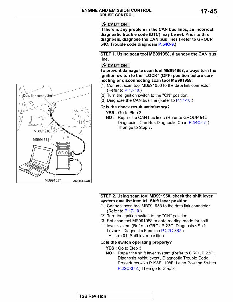
CAUTIONIf there is any problem in the CAN bus lines, an incorrect diagnostic trouble code (DTC) may be set. Prior to this diagnosis, diagnose the CAN bus lines (Refer to GROUP 54C, Trouble code diagnosis P.54C-9.)
STEP 1. Using scan tool MB991958, diagnose the CAN bus line.
CAUTIONTo prevent damage to scan tool MB991958, always turn the ignition switch to the "LOCK" (OFF) position before con-necting or disconnecting scan tool MB991958.(1) Connect scan tool MB991958 to the data link connector
(Refer to P.17-10.)(2) Turn the ignition switch to the "ON" position.(3) Diagnose the CAN bus line (Refer to P.17-10.)Q: Is the check result satisfactory?
YES : Go to Step 2NO : Repair the CAN bus lines (Refer to GROUP 54C,
Diagnosis − Can Bus Diagnostic Chart P.54C-15.) Then go to Step 7.
STEP 2. Using scan tool MB991958, check the shift lever system data list item 01: Shift lever position.(1) Connect scan tool MB991958 to the data link connector
(Refer to P.17-10.)(2) Turn the ignition switch to the "ON" position.(3) Set scan tool MB991958 to data reading mode for shift
lever system (Refer to GROUP 22C, Diagnosis <Shift Lever> − Diagnostic Function P.22C-367.)
• Item 01: Shift lever position.Q: Is the switch operating properly?
YES : Go to Step 3.NO : Repair the shift lever system (Refer to GROUP 22C,
Diagnosis <shift lever>, Diagnostic Trouble Code Procedures − No.P198E, 198F: Lever Position Switch P.22C-372.) Then go to Step 7.
AC608435
Data link connector
MB991827
MB991824
MB991910
AB
TSB Revision
CRUISE CONTROLENGINE AND EMISSION CONTROL17-46
STEP 3. Using scan tool MB991958, read the shift lever system DTC.(1) Connect scan tool MB991958 to the data link connector
(Refer to P.17-10.)(2) Turn the ignition switch to the "ON" position.(3) Check for shift lever system DTC (Refer to GROUP 22C,
Diagnosis <Shift Lever> − Diagnostic Function P.22C-367.)Q: Is any DTC set?
YES : Repair the shift lever system (Refer to GROUP 22C, Diagnosis <shift lever> − Diagnostic Trouble Code Char P.22C-370.) Then go to Step 7.
NO : Go to Step 4.
STEP 4. Using scan tool MB991958, read the TC-SST system DTC.(1) Connect scan tool MB991958 to the data link connector
(Refer to P.17-10.)(2) Turn the ignition switch to the "ON" position.(3) Check for shift lever system DTC (Refer to GROUP 22C,
Diagnosis <TC-SST> − Diagnostic Function P.22C-10.)Q: Is any DTC set?
YES : Repair the TC-SST system (Refer to GROUP 22C, Diagnosis <TC-SST> − Diagnostic Trouble Code Chart P.22C-15.) Then go to Step 7.
NO : Go to Step 5.
STEP 5. Using scan tool MB991958, check data list item 88: Neutral switch.(1) Connect scan tool MB991958 to the data link connector
(Refer to P.17-10.)(2) Turn the ignition switch to the "ON" position.(3) Set scan tool MB991958 to data reading mode for cruise
control system (Refer to P.17-10.)• Item 88: Neutral switch.
• When shift lever is at the "N" or "P" position, the dis-play on scan tool MB991958 should be "ON".
• When shift lever is other than "N" or "P" position, the display on scan tool MB991958 should be "OFF".
Q: Is the switch operating properly?YES : Go to Step 6.NO : Replace the ECM [Refer to GROUP 13A, Engine
Control Module (ECM) P.13A-888.] When the ECM is replaced, register the encrypted code (Refer to GROUP 42C, Diagnosis − ID Code Registration Judgment Table P.42C-9.) Then go to Step 7.
TSB Revision
CRUISE CONTROLENGINE AND EMISSION CONTROL 17-47
STEP 6. Check the symptoms.Q: When the shift lever is moved to "N" position, is the
cruise control cancelled?YES : It can be assumed that this malfunction is intermittent
(Refer to GROUP 00, How to Use Troubleshooting/Inspection Service Points − How to Cope with Intermittent Malfunction P.00-15.)
NO : Replace the ECM [Refer to GROUP 13A, Engine Control Module (ECM) P.13A-888.] When the ECM is replaced, register the encrypted code (Refer to GROUP 42C, Diagnosis − ID Code Registration Judgment Table P.42C-9.) Then go to Step 7.
STEP 7. Check the symptoms.Q: When the shift lever is moved to "N" position, is the
cruise control cancelled?YES : The procedure is complete.NO : Return to Step 1.
Inspection Procedure 4: When the "CANCEL" Switch is Pressed, Cruise Control is not Cancelled.
.
COMMENTThe cause is probably an open-circuit in the output circuit inside the "CANCEL" switch..
TROUBLESHOOTING HINTS (THE MOST LIKELY CAUSES FOR THIS CASE:)
• Malfunction of the cruise control switch.• Malfunction of the ECM.
DIAGNOSTIC PROCEDURERequired Special Tools:• MB991958: Scan Tool (M.U.T.-III Sub Assembly)
• MB991824: V.C.I.• MB991827: M.U.T.-III USB Cable• MB991910: M.U.T.-III Main Harness A
TSB Revision
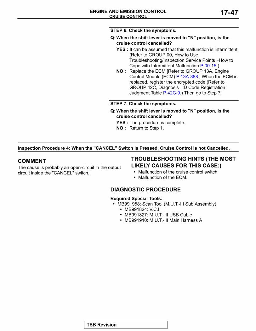
CRUISE CONTROLENGINE AND EMISSION CONTROL17-48
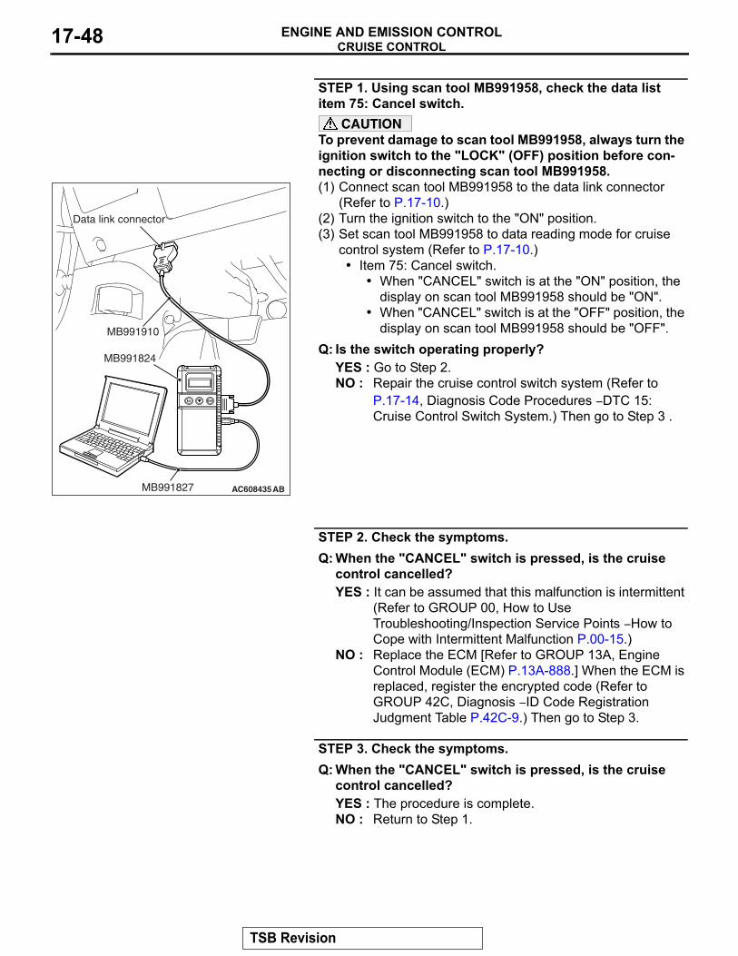
STEP 1. Using scan tool MB991958, check the data list item 75: Cancel switch.
CAUTIONTo prevent damage to scan tool MB991958, always turn the ignition switch to the "LOCK" (OFF) position before con-necting or disconnecting scan tool MB991958. (1) Connect scan tool MB991958 to the data link connector
(Refer to P.17-10.)(2) Turn the ignition switch to the "ON" position.(3) Set scan tool MB991958 to data reading mode for cruise
control system (Refer to P.17-10.)• Item 75: Cancel switch.
• When "CANCEL" switch is at the "ON" position, the display on scan tool MB991958 should be "ON".
• When "CANCEL" switch is at the "OFF" position, the display on scan tool MB991958 should be "OFF".
Q: Is the switch operating properly?YES : Go to Step 2.NO : Repair the cruise control switch system (Refer to
P.17-14, Diagnosis Code Procedures − DTC 15: Cruise Control Switch System.) Then go to Step 3 .
STEP 2. Check the symptoms.Q: When the "CANCEL" switch is pressed, is the cruise
control cancelled?YES : It can be assumed that this malfunction is intermittent
(Refer to GROUP 00, How to Use Troubleshooting/Inspection Service Points − How to Cope with Intermittent Malfunction P.00-15.)
NO : Replace the ECM [Refer to GROUP 13A, Engine Control Module (ECM) P.13A-888.] When the ECM is replaced, register the encrypted code (Refer to GROUP 42C, Diagnosis − ID Code Registration Judgment Table P.42C-9.) Then go to Step 3.
STEP 3. Check the symptoms.Q: When the "CANCEL" switch is pressed, is the cruise
control cancelled?YES : The procedure is complete.NO : Return to Step 1.
AC608435
Data link connector
MB991827
MB991824
MB991910
AB
TSB Revision
CRUISE CONTROLENGINE AND EMISSION CONTROL 17-49
Inspection Procedure 5: Cruise Control cannot be Set (No Response "COAST/SET" Switch and "ACC/RES" Switch is Pressed.)
.
COMMENT• The fail-safe function is probably canceling cruise
control system. In this case, checking the cruise control system, MFI system, TC-SST system, shift lever system and CAN bus line system DTCs. The scan tool MB991958 can also be used to check if the circuits of each input switch are normal or not by checking the data list.
• In addition, if the option coding data written into the ECM is not normal, the cruise control system does not work.
NOTE: Press the cruise control switches one by one securely. Otherwise, the cruise control system may not be started.
.
TROUBLESHOOTING HINTS (THE MOST LIKELY CAUSES FOR THIS CASE:)
• Malfunction of the CAN bus line system.• ECM option coding data error • Malfunction of the MFI system.• Malfunction of the TC-SST system <TC-SST.>• Malfunction of the shift lever system <TC-SST.>• Malfunction of the cruise control switch.• Malfunction of the stoplight switch.• Malfunction of the clutch switch <M/T.>• Malfunction of the TC-SST-ECU <TC-SST.>• Malfunction of the shift lever ECU <TC-SST.>• Malfunction of the ECM.
DIAGNOSTIC PROCEDURERequired Special Tools:• MB991958: Scan Tool (M.U.T.-III Sub Assembly)
• MB991824: V.C.I.• MB991827: M.U.T.-III USB Cable• MB991910: M.U.T.-III Main Harness A
TSB Revision
CRUISE CONTROLENGINE AND EMISSION CONTROL17-50
CAUTIONIf there is any problem in the CAN bus lines, an incorrect diagnostic trouble code (DTC) may be set. Prior to this diagnosis, diagnose the CAN bus lines (Refer to GROUP 54C, Trouble code diagnosis P.54C-9.)
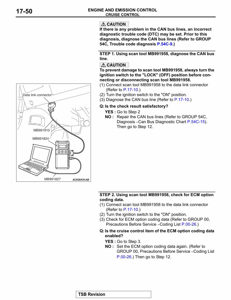
STEP 1. Using scan tool MB991958, diagnose the CAN bus line.
CAUTIONTo prevent damage to scan tool MB991958, always turn the ignition switch to the "LOCK" (OFF) position before con-necting or disconnecting scan tool MB991958.(1) Connect scan tool MB991958 to the data link connector
(Refer to P.17-10.)(2) Turn the ignition switch to the "ON" position.(3) Diagnose the CAN bus line (Refer to P.17-10.)Q: Is the check result satisfactory?
YES : Go to Step 2NO : Repair the CAN bus lines (Refer to GROUP 54C,
Diagnosis − Can Bus Diagnostic Chart P.54C-15). Then go to Step 12.
STEP 2. Using scan tool MB991958, check for ECM option coding data.(1) Connect scan tool MB991958 to the data link connector
(Refer to P.17-10.)(2) Turn the ignition switch to the "ON" position.(3) Check for ECM option coding data (Refer to GROUP 00,
Precautions Before Service − Coding List P.00-26.)Q: Is the cruise control item of the ECM option coding data
enabled?YES : Go to Step 3.NO : Set the ECM option coding data again. (Refer to
GROUP 00, Precautions Before Service − Coding List P.00-26.) Then go to Step 12.
AC608435
Data link connector
MB991827
MB991824
MB991910
AB
TSB Revision
CRUISE CONTROLENGINE AND EMISSION CONTROL 17-51
STEP 3. Using scan tool MB991958, check for MFI system DTC.(1) Connect scan tool MB991958 to the data link connector
(Refer to P.17-10.)(2) Turn the ignition switch to the "ON" position.(3) Check for MFI system DTC (Refer to GROUP 13A,
Diagnosis − Diagnostic Function P.13A-9.)Q: Is any DTC set?
YES : Repair the MFI system (Refer to GROUP 13A, Diagnosis − Diagnostic Trouble Code Chart P.13A-48.) Then go to Step 12.
NO : Go to Step 6 <M/T.>NO : Go to Step 4 <TC-SST.>
STEP 4. Using scan tool MB991958, check for TC-SST system DTC <TC-SST.>(1) Connect scan tool MB991958 to the data link connector
(Refer to P.17-10.)(2) Turn the ignition switch to the "ON" position.(3) Check for TC-SST system DTC (Refer to GROUP 22C,
Diagnosis <TC-SST> − Diagnostic Function P.22C-10.)Q: Is any DTC set?
YES : Repair the TC-SST system (Refer to GROUP 22C, Diagnosis <TC-SST> − Diagnostic Trouble Code Chart P.22C-370.) Then go to Step 12.
NO : Go to Step 5.
STEP 5. Using scan tool MB991958, check for shift lever system DTC <TC-SST.>(1) Connect scan tool MB991958 to the data link connector
(Refer to P.17-10.)(2) Turn the ignition switch to the "ON" position.(3) Check for shift lever system DTC (Refer to GROUP 22C,
Diagnosis <shift lever> − Diagnostic Function P.22C-367.)Q: Is any DTC set?
YES : Repair the shift lever system (Refer to GROUP 22C, Diagnosis <shift lever> − Diagnostic Trouble Code Chart P.22C-370.) Then go to Step 12.
NO : Go to Step 6.
TSB Revision
CRUISE CONTROLENGINE AND EMISSION CONTROL17-52
STEP 6. Check for cruise control system DTC.(1) Disconnect the negative (−) battery terminal, to erase the
DTC of the cruise control system.(2) Connect the negative (−) battery terminal.(3) Turn the ignition switch to the "ON" position, and press the
"ON/OFF" switch to turn the cruise control system to ON (turn on the "CRUISE" indicator light.)
(4) After turning the cruise control system to ON, when 2 minutes or more has elapsed without operating the cruise control switches.
(5) With the cruise control switches not operated, depress the brake pedal for several seconds, and then read the DTC of the cruise control system (Refer to P.17-10.)
Q: Is any DTC set?YES : Repair the cruise control system (Refer to P.17-13,
Diagnostic Trouble Code Chart.) Then go to Step 12.NO : Go to Step 7.
TSB Revision
CRUISE CONTROLENGINE AND EMISSION CONTROL 17-53
STEP 7. Using scan tool MB991958, check data list item 75: Cancel switch, item 86: Main switch, item 91: Resume switch and item 92: Set switch.(1) Connect scan tool MB991958 to the data link connector
(Refer to P.17-10.)(2) Turn the ignition switch to the "ON" position.(3) Set scan tool MB991958 to data reading mode for cruise
control system (Refer to P.17-10.)• Item 75: Cancel switch.
• When "CANCEL" switch is at the "ON" position, the display on scan tool MB991958 should be "ON".
• When "CANCEL" switch is at the "OFF" position, the display on scan tool MB991958 should be "OFF".
• Item 86: Main switch.• When "ON/OFF" switch is at the "ON" position, the
display on scan tool MB991958 should be "ON".• When "ON/OFF" switch is at the "OFF" position, the
display on scan tool MB991958 should be "OFF".• Item 91: Resume switch.
• When "ACC/RES" switch is at the "ON" position, the display on scan tool MB991958 should be "ON".
• When "ACC/RES" switch is at the "OFF" position, the display on scan tool MB991958 should be "OFF".
• Item 92: Set switch.• When "COAST/SET" switch is at the "ON" position,
the display on scan tool MB991958 should be "ON".• When "COAST/SET" switch is at the "OFF" position,
the display on scan tool MB991958 should be "OFF".
Q: Is the switch operating properly?YES : Go to Step 8.NO : Repair the cruise control switch system (Refer to
P.17-14, Diagnostic Trouble Code Procedures − DTC 15: Cruise Control Switch System.) Then go to Step 12.
TSB Revision
CRUISE CONTROLENGINE AND EMISSION CONTROL17-54
STEP 8. Using scan tool MB991958, check data list item 74: Brake light switch and item 89: Normally closed brake switch.(1) Connect scan tool MB991958 to the data link connector
(Refer to P.17-10.)(2) Turn the ignition switch to the "ON" position.(3) Set scan tool MB991958 to data reading mode for cruise
control system (Refer to P.17-10.)• Item 74: Brake light switch.
• When the brake pedal is depressed, the display on scan tool MB991958 should be "ON".
• When the brake pedal is released, the display on scan tool MB991958 should be "OFF".
• Item 89: Normally closed brake switch.• When the brake pedal is depressed, the display on
scan tool MB991958 should be "ON".• When the brake pedal is released, the display on
scan tool MB991958 should be "OFF".Q: Is the switch operating properly?
YES : Go to Step 9 <M/T.>YES : Go to Step 10 <TC-SST.>NO : Repair the stoplight switch system (Refer to P.17-27,
Diagnostic Trouble Code Procedures − DTC 22: Stoplight Switch System.) Then go to Step 12.
STEP 9. Using scan tool MB991958, check data list item 78: Clutch switch <M/T.>(1) Connect scan tool MB991958 to the data link connector
(Refer to P.17-10.)(2) Turn the ignition switch to the "ON" position.(3) Set scan tool MB991958 to data reading mode for cruise
control system (Refer to P.17-10.)• Item 78: Clutch switch.
• When the clutch pedal is depressed, the display on scan tool MB991958 should be "ON".
• When the clutch pedal is released, the display on scan tool MB991958 should be "OFF".
Q: Is the switch operating properly?YES : Go to Step 11.NO : Repair the clutch switch system (Refer to P.17-41,
Symptom Procedures − Inspection Procedure 2.) Then go to Step 12.
TSB Revision
CRUISE CONTROLENGINE AND EMISSION CONTROL 17-55
STEP 10. Using scan tool MB991958, check data list item 88: Neutral switch <TC-SST.>(1) Connect scan tool MB991958 to the data link connector
(Refer to P.17-10.)(2) Turn the ignition switch to the "ON" position.(3) Set scan tool MB991958 to data reading mode for cruise
control system (Refer to P.17-10.)• Item 88: Neutral switch.
• When shift lever is at the "N", "P", "R" position, the display on scan tool MB991958 should be "ON".
• When shift lever is other than "N", "P", "R" position, the display on scan tool MB991958 should be "OFF".
Q: Is the switch operating properly?YES : Go to Step 11.NO : Repair the shift lever system (Refer to P.17-44,
Symptom Procedures − Inspection Procedure 3.) Then go to Step 12.
STEP 11. Check the symptoms.Q: Can cruise control be set?
YES : It can be assumed that this malfunction is intermittent (Refer to GROUP 00, How to Use Troubleshooting/Inspection Service Points − How to Cope with Intermittent Malfunction P.00-15.)
NO : Replace the ECM [Refer to GROUP 13A, Engine Control Module (ECM) P.13A-888.] When the ECM is replaced, register the encrypted code (Refer to GROUP 42C, Diagnosis − ID Code Registration Judgment Table P.42C-9.) Then go to Step 12.
STEP 12. Check the symptoms.Q: Can cruise control be set?
YES : The procedure is complete.NO : Return to Step 1.
TSB Revision
CRUISE CONTROLENGINE AND EMISSION CONTROL17-56
Inspection Procedure 6: Hunting (Repeated Acceleration and Deceleration) Occurs at the Set Vehicle Speed.
.
COMMENT• The wheel speed sensor signal (vehicle speed
signal) or the throttle body is suspected.• The wheel speed sensor signal (vehicle speed
signal) is transmitted from the ASC-ECU to the ECM via CAN bus line.
.
TROUBLESHOOTING HINTS (THE MOST LIKELY CAUSES FOR THIS CASE:)
• Malfunction of the CAN bus line system.• Malfunction of the ASC system• Malfunction of the MFI system• Malfunction of the throttle body.• Malfunction of the ECM.
DIAGNOSTIC PROCEDURERequired Special Tools:• MB991958: Scan Tool (M.U.T.-III Sub Assembly)
• MB991824: V.C.I.• MB991827: M.U.T.-III USB Cable• MB991910: M.U.T.-III Main Harness A
CAUTIONIf there is any problem in the CAN bus lines, an incorrect diagnostic trouble code (DTC) may be set. Prior to this diagnosis, diagnose the CAN bus lines (Refer to GROUP 54C, Trouble code diagnosis P.54C-9.)
STEP 1. Using scan tool MB991958, diagnose the CAN bus line.
CAUTIONTo prevent damage to scan tool MB991958, always turn the ignition switch to the "LOCK" (OFF) position before con-necting or disconnecting scan tool MB991958.(1) Connect scan tool MB991958 to the data link connector
(Refer to P.17-10.)(2) Turn the ignition switch to the "ON" position.(3) Diagnose the CAN bus line (Refer to P.17-10.)Q: Is the check result satisfactory?
YES : Go to Step 2NO : Repair the CAN bus lines (Refer to GROUP 54C,
Diagnosis − Can Bus Diagnostic Chart P.54C-15.) Then go to Step 6.
AC608435
Data link connector
MB991827
MB991824
MB991910
AB
TSB Revision
CRUISE CONTROLENGINE AND EMISSION CONTROL 17-57
STEP 2. Using scan tool MB991958, check for ASC system DTC.(1) Connect scan tool MB991958 to the data link connector
(Refer to P.17-10.)(2) Turn the ignition switch to the "ON" position.(3) Check for ASC system DTC (Refer to GROUP 35C,
Diagnosis − Diagnostic Function P.35C-8.)Q: Is any DTC set?
YES : Repair the ASC system (Refer to GROUP 35C, Diagnosis − Diagnostic Trouble Code Chart P.35C-22.) Then go to Step 6.
NO : Go to Step 3.
STEP 3. Using scan tool MB991958, check for MFI system DTC.(1) Connect scan tool MB991958 to the data link connector
(Refer to P.17-10.)(2) Turn the ignition switch to the "ON" position.(3) Check for MFI system DTC (Refer to GROUP 13A,
Diagnosis − Diagnostic Function P.13A-9.)Q: Is any DTC set?
YES : Repair the MFI system (Refer to GROUP 13A, Diagnosis − Diagnostic Trouble Code Chart P.13A-48.) Then go to Step 6.
NO : Go to Step 4.
STEP 4. Using scan tool MB991958, check data list item 04: Vehicle speed.(1) Connect scan tool MB991958 to the data link connector
(Refer to P.17-10.)(2) Turn the ignition switch to the "ON" position.(3) Set scan tool MB991958 to data reading mode for cruise
control system (Refer to P.17-10.)• Item 04: Vehicle speed.
Q: Is the check result satisfactory?YES : Go to Step 5.NO : Replace the ECM [Refer to GROUP 13A, Engine
Control Module (ECM) P.13A-888.] When the ECM is replaced, register the encrypted code (Refer to GROUP 42C, Diagnosis − ID Code Registration Judgment Table P.42C-9.) Then go to Step 6.
TSB Revision

CRUISE CONTROLENGINE AND EMISSION CONTROL17-58
STEP 5. Check the symptoms.Q: Does hunting occur?
YES : Replace the ECM [Refer to GROUP 13A, Engine Control Module (ECM) P.13A-888.] When the ECM is replaced, register the encrypted code (Refer to GROUP 42C, Diagnosis − ID Code Registration Judgment Table P.42C-9.) Then go to Step 6.
NO : It can be assumed that this malfunction is intermittent (Refer to GROUP 00, How to Use Troubleshooting/Inspection Service Points − How to Cope with Intermittent Malfunction P.00-15.)
STEP 6. Check the symptoms.Q: Does hunting occur?
YES : Return to Step 1.NO : The procedure is complete.
Inspection Procedure 7: When the "ON/OFF" Switch is Turned ON, "CRUISE" Indicator Light does not Illuminate (However, Cruise Control System is Normal.)
.
CIRCUIT OPERATION• The ECM detects "ON/OFF" switch ON signal to
illuminate the "CRUISE" indicator light.• The "CRUISE" indicator light illuminate signal is
transmitted from the ECM to the combination meter via CAN bus line.
.
COMMENT• The CAN bus line between the ECM and the
ETACS-ECU and between the ETACS-ECU and the combination meter may be defective.
• The combination meter, ETACS-ECU or ECM may also be defective.
.
TROUBLESHOOTING HINTS (THE MOST LIKELY CAUSES FOR THIS CASE:)
• Malfunction of CAN bus system.• Damaged harness or connector.• Malfunction of the combination meter.• Malfunction of the ETACS-ECU.• Malfunction of the ECM.
DIAGNOSTIC PROCEDURERequired Special Tools:• MB991958: Scan Tool (M.U.T.-III Sub Assembly)
• MB991824: V.C.I.• MB991827: M.U.T.-III USB Cable• MB991910: M.U.T.-III Main Harness A
TSB Revision
CRUISE CONTROLENGINE AND EMISSION CONTROL 17-59
CAUTIONIf there is any problem in the CAN bus lines, an incorrect diagnostic trouble code (DTC) may be set. Prior to this diagnosis, diagnose the CAN bus lines (Refer to GROUP 54C, Trouble code diagnosis P.54C-9.)
STEP 1. Using scan tool MB991958, diagnose the CAN bus line.
CAUTIONTo prevent damage to scan tool MB991958, always turn the ignition switch to the "LOCK" (OFF) position before con-necting or disconnecting scan tool MB991958.(1) Connect scan tool MB991958 to the data link connector
(Refer to P.17-10.)(2) Turn the ignition switch to the "ON" position.(3) Diagnose the CAN bus line (Refer to P.17-10.)Q: Is the check result satisfactory?
YES : Go to Step 2NO : Repair the CAN bus lines (Refer to GROUP 54C,
Diagnosis − Can Bus Diagnostic Chart P.54C-15.) Then go to Step 6.
STEP 2. Using scan tool MB991958, check for MFI system DTC.(1) Connect scan tool MB991958 to the data link connector
(Refer to P.17-10.)(2) Turn the ignition switch to the "ON" position.(3) Check for MFI system DTC (Refer to GROUP 13A,
Diagnosis − Diagnostic Function P.13A-9.)Q: Is DTC U0141 set?
YES : Repair the MFI system (Refer to GROUP 13A, Diagnosis, Diagnostic Trouble Code Procedures − DTC U0141: ETACS-ECU CAN Communication Time Out P.13A-694.) Then go to Step 6.
NO : Go to Step 3.
AC608435
Data link connector
MB991827
MB991824
MB991910
AB
TSB Revision
CRUISE CONTROLENGINE AND EMISSION CONTROL17-60
STEP 3. Using scan tool MB991958, check for ETACS system DTC.(1) Connect scan tool MB991958 to the data link connector
(Refer to P.17-10.)(2) Turn the ignition switch to the "ON" position.(3) Check for ETACS system DTC (Refer to GROUP 54A,
ETACS, Troubleshooting − Diagnostic Function P.54A-643.)Q: Is DTC U0155 set?
YES : Repair the ETACS system (Refer to GROUP 54A, ETACS, Troubleshooting, Diagnostic Trouble Code Procedures − DTC U0155: Combination Meter-ECU CAN Communication Time Out P.54A-665.) Then go to Step 6.
NO : Go to Step 4.
STEP 4. Using scan tool MB991958, check the combination meter system actuator test item 7: Cruise indicator 1.(1) Connect scan tool MB991958 to the data link connector
(Refer to P.17-10.)(2) Turn the ignition switch to the "ON" position.(3) Set scan tool MB991958 to check the actuator test for
combination meter system item 7: indicator 1 (Refer to GROUP 54A, Combination Meter, Troubleshooting − Actuator Teat Table P.54A-96.)
Q: Is the check result satisfactory?YES : Go to Step 5.NO : Repair the combination meter system (Refer to
GROUP 54A, Combination Meter, Troubleshooting, Symptom Procedures − Inspection Procedure 5: The combination meter light does not illuminate normally or the multi information display is not displayed normally P.54A-81.) Then go to Step 6.
STEP 5. Check the symptoms.Q: When the "ON/OFF" switch is turned ON, is the
"CRUISE" indicator light illuminated?YES : It can be assumed that this malfunction is intermittent
(Refer to GROUP 00, How to Use Troubleshooting/Inspection Service Points − How to Cope with Intermittent Malfunction P.00-15.)
NO : Replace the ECM [Refer to GROUP 13A, Engine Control Module (ECM) P.13A-888.] When the ECM is replaced, register the encrypted code (Refer to GROUP 42C, Diagnosis − ID Code Registration Judgment Table P.42C-9.) Then go to Step 6.
STEP 6. Check the symptoms.Q: When the "ON/OFF" switch is turned ON, is the
"CRUISE" indicator light illuminated?YES : The procedure is complete.NO : Return to Step 1.
TSB Revision
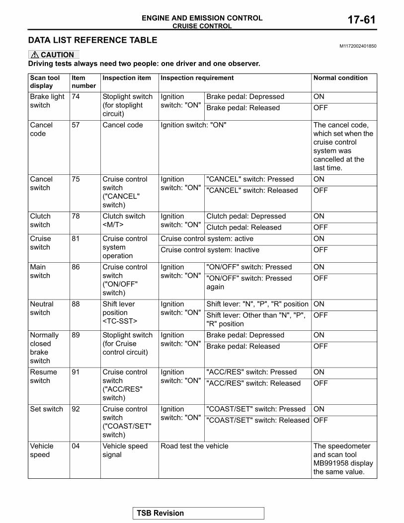
CRUISE CONTROLENGINE AND EMISSION CONTROL 17-61
DATA LIST REFERENCE TABLEM1172002401850
CAUTIONDriving tests always need two people: one driver and one observer.
Scan tool display
Item number
Inspection item Inspection requirement Normal condition
Brake light switch
74 Stoplight switch (for stoplight circuit)
Ignition switch: "ON"
Brake pedal: Depressed ONBrake pedal: Released OFF
Cancel code
57 Cancel code Ignition switch: "ON" The cancel code, which set when the cruise control system was cancelled at the last time.
Cancel switch
75 Cruise control switch ("CANCEL" switch)
Ignition switch: "ON"
"CANCEL" switch: Pressed ON"CANCEL" switch: Released OFF
Clutch switch
78 Clutch switch <M/T>
Ignition switch: "ON"
Clutch pedal: Depressed ONClutch pedal: Released OFF
Cruise switch
81 Cruise control system operation
Cruise control system: active ONCruise control system: Inactive OFF
Main switch
86 Cruise control switch ("ON/OFF" switch)
Ignition switch: "ON"
"ON/OFF" switch: Pressed ON"ON/OFF" switch: Pressed again
OFF
Neutral switch
88 Shift lever position <TC-SST>
Ignition switch: "ON"
Shift lever: "N", "P", "R" position ONShift lever: Other than "N", "P", "R" position
OFF
Normally closed brake switch
89 Stoplight switch (for Cruise control circuit)
Ignition switch: "ON"
Brake pedal: Depressed ONBrake pedal: Released OFF
Resume switch
91 Cruise control switch ("ACC/RES" switch)
Ignition switch: "ON"
"ACC/RES" switch: Pressed ON"ACC/RES" switch: Released OFF
Set switch 92 Cruise control switch ("COAST/SET" switch)
Ignition switch: "ON"
"COAST/SET" switch: Pressed ON"COAST/SET" switch: Released OFF
Vehicle speed
04 Vehicle speed signal
Road test the vehicle The speedometer and scan tool MB991958 display the same value.
TSB Revision
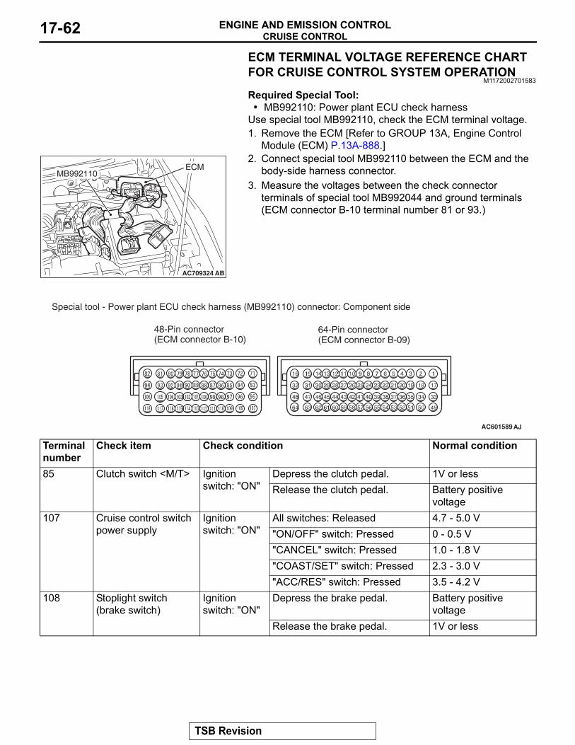
CRUISE CONTROLENGINE AND EMISSION CONTROL17-62
ECM TERMINAL VOLTAGE REFERENCE CHART FOR CRUISE CONTROL SYSTEM OPERATION
M1172002701583
Required Special Tool:• MB992110: Power plant ECU check harness
Use special tool MB992110, check the ECM terminal voltage.1. Remove the ECM [Refer to GROUP 13A, Engine Control
Module (ECM) P.13A-888.]2. Connect special tool MB992110 between the ECM and the
body-side harness connector.3. Measure the voltages between the check connector
terminals of special tool MB992044 and ground terminals (ECM connector B-10 terminal number 81 or 93.)
AC709324 AB
MB992110ECM
AC601589 AJ
Special tool - Power plant ECU check harness (MB992110) connector: Component side
48-Pin connector(ECM connector B-10)
64-Pin connector(ECM connector B-09)
Terminal number
Check item Check condition Normal condition
85 Clutch switch <M/T> Ignition switch: "ON"
Depress the clutch pedal. 1V or lessRelease the clutch pedal. Battery positive
voltage107 Cruise control switch
power supplyIgnition switch: "ON"
All switches: Released 4.7 - 5.0 V "ON/OFF" switch: Pressed 0 - 0.5 V "CANCEL" switch: Pressed 1.0 - 1.8 V "COAST/SET" switch: Pressed 2.3 - 3.0 V "ACC/RES" switch: Pressed 3.5 - 4.2 V
108 Stoplight switch (brake switch)
Ignition switch: "ON"
Depress the brake pedal. Battery positive voltage
Release the brake pedal. 1V or less
TSB Revision

CRUISE CONTROLENGINE AND EMISSION CONTROL 17-63
SPECIAL TOOLSM1172000601513
Tool Tool number and name Supersession ApplicationMB991958a: MB991824b: MB991827c: MB991910d: MB991911e: MB991914f: MB991825g: MB991826Scan tool (M.U.T.-III sub assembly)a: Vehicle
communication interface (V. C. I.)
b: M.U.T.-III USB cablec: M.U.T.-III main
harness A (Vehicles with CAN communication system)
d: M.U.T.-III main harness B (Vehicles without CAN communication system)
e: M.U.T.-III main harness C (for Chrysler models only)
f: M.U.T.-III measurement adapter
g: M.U.T.-III trigger harness
MB991824-KITNOTE: g: MB991826 M.U.T.-III Trigger Harness is not necessary when pushing V.C.I. ENTER key.
CAUTIONFor vehicles with CAN communication, use M.U.T.-III main harness A to send simulated vehicle speed. If you connect M.U.T.-III main harness B instead, the CAN communication does not function correctly.• Checking DTC.• Checking data list.
MB991910
MB991826
MB991958
MB991911
MB991914
MB991824
MB991827
MB991825
Do not use
a
b
c
d
e
f
g
Do not use
TSB Revision
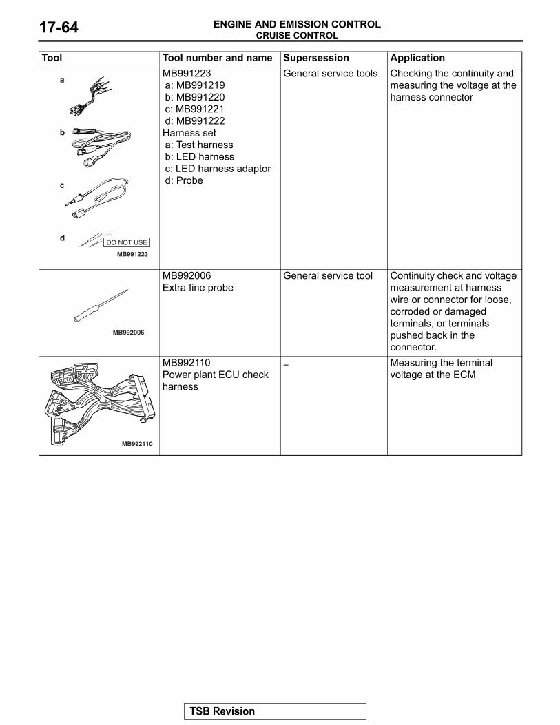
CRUISE CONTROLENGINE AND EMISSION CONTROL17-64
MB991223a: MB991219b: MB991220c: MB991221d: MB991222Harness seta: Test harnessb: LED harnessc: LED harness adaptord: Probe
General service tools Checking the continuity and measuring the voltage at the harness connector
MB992006Extra fine probe
General service tool Continuity check and voltage measurement at harness wire or connector for loose, corroded or damaged terminals, or terminals pushed back in the connector.
MB992110Power plant ECU check harness
− Measuring the terminal voltage at the ECM
Tool Tool number and name Supersession Application
MB991223
a
d
c
b
DO NOT USE
BF
MB992006
MB992110
TSB Revision
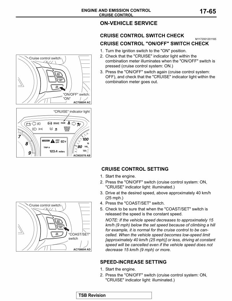
CRUISE CONTROLENGINE AND EMISSION CONTROL 17-65
ON-VEHICLE SERVICE
CRUISE CONTROL SWITCH CHECKM1172001201165
CRUISE CONTROL "ON/OFF" SWITCH CHECK1. Turn the ignition switch to the "ON" position.2. Check that the "CRUISE" indicator light within the
combination meter illuminates when the "ON/OFF" switch is pressed (cruise control system: ON.)
3. Press the "ON/OFF" switch again (cruise control system: OFF), and check that the "CRUISE" indicator light within the combination meter goes out.
CRUISE CONTROL SETTING1. Start the engine.2. Press the "ON/OFF" switch (cruise control system: ON,
"CRUISE" indicator light: illuminated.)3. Drive at the desired speed, above approximately 40 km/h
(25 mph.)4. Press the "COAST/SET" switch.5. Check to be sure that when the "COAST/SET" switch is
released the speed is the constant speed.NOTE: If the vehicle speed decreases to approximately 15 km/h (9 mph) below the set speed because of climbing a hill for example, it is normal for the cruise control to be can-celled. When the vehicle speed becomes low-speed limit [approximately 40 km/h (25 mph)] or less, driving at constant speed will be cancelled even if the vehicle speed does not decrease 15 km/h (9 mph) or more.
SPEED-INCREASE SETTING1. Start the engine.2. Press the "ON/OFF" switch (cruise control system: ON,
"CRUISE" indicator light: illuminated.)
CANCEL
ACCRES
ONOFF
COASTSET
AC708694 AC
Cruise control switch
"ON/OFF" switch: "ON"
AC902078 AB
"CRUISE" indicator light
CANCEL
ACCRES
ONOFF
COASTSET
AC708694 AD
Cruise control switch
"COAST/SET"switch
TSB Revision
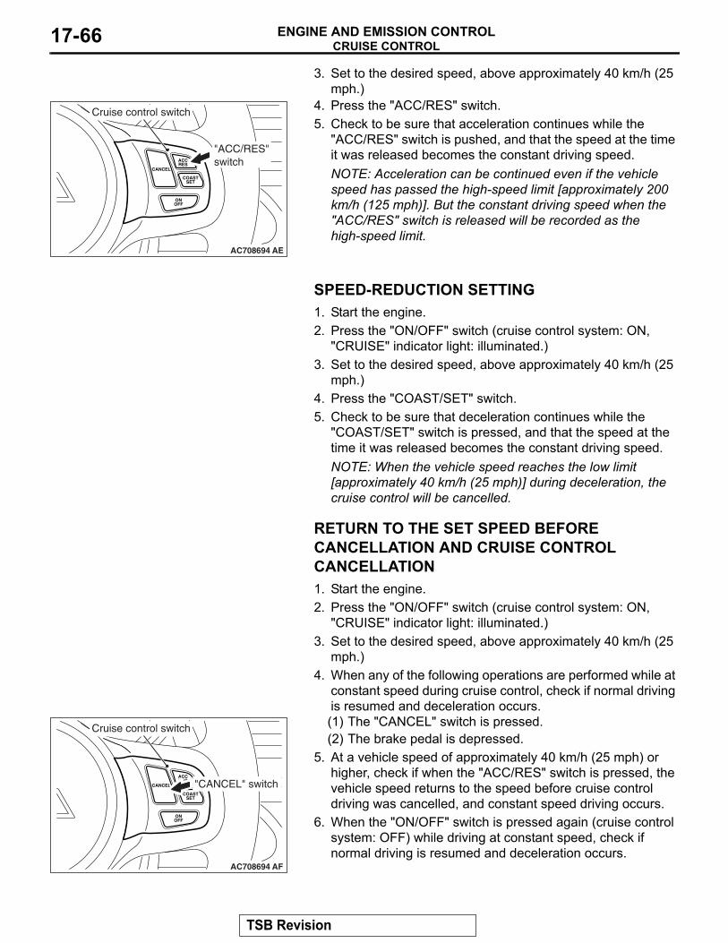
CRUISE CONTROLENGINE AND EMISSION CONTROL17-66
3. Set to the desired speed, above approximately 40 km/h (25 mph.)
4. Press the "ACC/RES" switch.5. Check to be sure that acceleration continues while the
"ACC/RES" switch is pushed, and that the speed at the time it was released becomes the constant driving speed.NOTE: Acceleration can be continued even if the vehicle speed has passed the high-speed limit [approximately 200 km/h (125 mph)]. But the constant driving speed when the "ACC/RES" switch is released will be recorded as the high-speed limit.
SPEED-REDUCTION SETTING1. Start the engine.2. Press the "ON/OFF" switch (cruise control system: ON,
"CRUISE" indicator light: illuminated.)3. Set to the desired speed, above approximately 40 km/h (25
mph.)4. Press the "COAST/SET" switch.5. Check to be sure that deceleration continues while the
"COAST/SET" switch is pressed, and that the speed at the time it was released becomes the constant driving speed.NOTE: When the vehicle speed reaches the low limit [approximately 40 km/h (25 mph)] during deceleration, the cruise control will be cancelled.
RETURN TO THE SET SPEED BEFORE CANCELLATION AND CRUISE CONTROL CANCELLATION1. Start the engine.2. Press the "ON/OFF" switch (cruise control system: ON,
"CRUISE" indicator light: illuminated.)3. Set to the desired speed, above approximately 40 km/h (25
mph.)4. When any of the following operations are performed while at
constant speed during cruise control, check if normal driving is resumed and deceleration occurs.(1) The "CANCEL" switch is pressed.(2) The brake pedal is depressed.
5. At a vehicle speed of approximately 40 km/h (25 mph) or higher, check if when the "ACC/RES" switch is pressed, the vehicle speed returns to the speed before cruise control driving was cancelled, and constant speed driving occurs.
6. When the "ON/OFF" switch is pressed again (cruise control system: OFF) while driving at constant speed, check if normal driving is resumed and deceleration occurs.
CANCEL
ACCRES
ONOFF
COASTSET
AC708694 AE
Cruise control switch
"ACC/RES"switch
CANCEL
ACCRES
ONOFF
COASTSET
AC708694 AF
Cruise control switch
"CANCEL" switch
TSB Revision
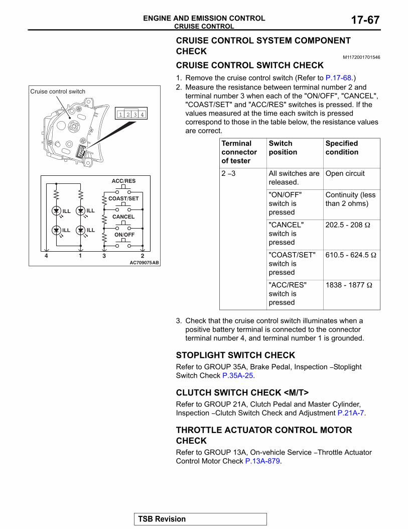
CRUISE CONTROLENGINE AND EMISSION CONTROL 17-67
CRUISE CONTROL SYSTEM COMPONENT CHECK
M1172001701546
CRUISE CONTROL SWITCH CHECK1. Remove the cruise control switch (Refer to P.17-68.)2. Measure the resistance between terminal number 2 and
terminal number 3 when each of the "ON/OFF", "CANCEL", "COAST/SET" and "ACC/RES" switches is pressed. If the values measured at the time each switch is pressed correspond to those in the table below, the resistance values are correct.
3. Check that the cruise control switch illuminates when a positive battery terminal is connected to the connector terminal number 4, and terminal number 1 is grounded.
STOPLIGHT SWITCH CHECKRefer to GROUP 35A, Brake Pedal, Inspection − Stoplight Switch Check P.35A-25.
CLUTCH SWITCH CHECK <M/T>Refer to GROUP 21A, Clutch Pedal and Master Cylinder, Inspection − Clutch Switch Check and Adjustment P.21A-7.
THROTTLE ACTUATOR CONTROL MOTOR CHECKRefer to GROUP 13A, On-vehicle Service − Throttle Actuator Control Motor Check P.13A-879.
Terminal connector of tester
Switch position
Specified condition
2 − 3 All switches are released.
Open circuit
"ON/OFF" switch is pressed
Continuity (less than 2 ohms)
"CANCEL" switch is pressed
202.5 - 208 Ω
"COAST/SET" switch is pressed
610.5 - 624.5 Ω
"ACC/RES" switch is pressed
1838 - 1877 Ω
AC70907521 34
1 2 3 4
AB
Cruise control switch
TSB Revision
EMISSION CONTROL <MFI - T/C>ENGINE AND EMISSION CONTROL17-68
CRUISE CONTROL SWITCHREMOVAL AND INSTALLATION
M1172007600395Since the cruise control switch is mounted on the spoke of the steering wheel garnish, refer to Steering Wheel for removal and installation (Refer to GROUP 37, Steering Wheel P.37-29.)
EMISSION CONTROL <MFI - T/C>GENERAL INFORMATION
M1173000101243
The emission control system consists of the fol-lowing subsystems:
• Positive crankcase ventilation (PCV) system
• Evaporative emission system• Exhaust emission control system
SERVICE SPECIFICATIONSM1173000301098
DIAGNOSISM1173000700231
SPECIAL TOOLM1173000601022
Item Standard valueEmission control systemEvaporative emission purge solenoid coil resistance [at 20° C (68° F)] Ω 22 − 26Evaporative emission ventilation solenoid coil resistance [at 20° C (68° F)] Ω 17 − 21
Purge flow cm3/s (SCFH) [at 80 − 95° C (176 − 205° F) with sudden revving] 20 (2.5)
SYMPTOM PROBABLE CAUSE REMEDYEngine will not start or hard to start
Vacuum hose disconnected or damaged Repair or replaceMalfunction of the evaporative emission purge solenoid
Repair or replace
Rough idle or engine stalls Vacuum hose disconnected or damaged. Repair or replaceMalfunction of the PCV valve ReplaceMalfunction of the purge control system Check the system; If there is a
problem, check its component parts.
Excessive oil consumption PCV line clogged Check PCV system
Tool Tool number and name Supersession ApplicationMB995061Purge flow indicator
MLR6890APart of MIT280220
Inspection of purge control system
TSB Revision
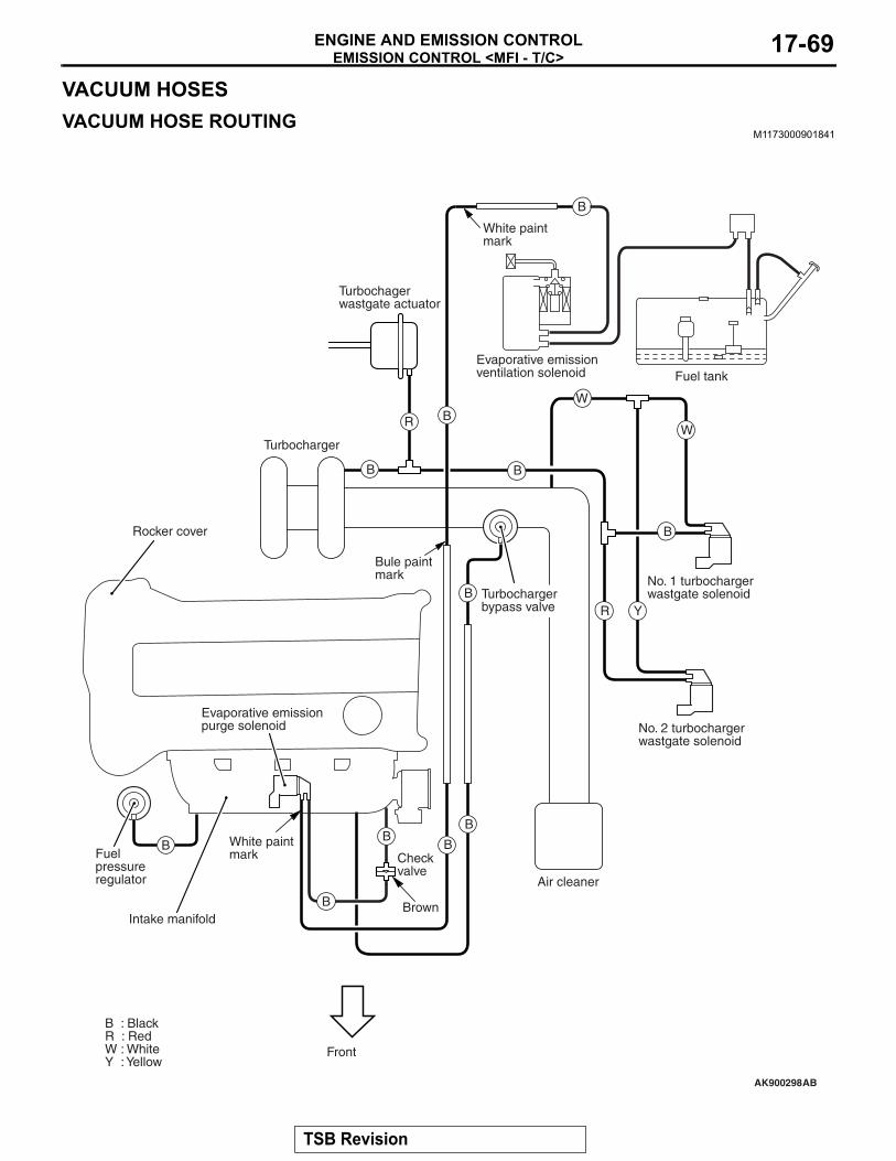
EMISSION CONTROL <MFI - T/C>ENGINE AND EMISSION CONTROL 17-69
VACUUM HOSESVACUUM HOSE ROUTING
M1173000901841
AK900298
B
BB
B
B
R BW
B
R Y
W
B
B
B
B
Intake manifold
Front
White paintmark
B : BlackR : RedW : WhiteY : Yellow
No. 1 turbochargerwastgate solenoid
Evaporative emissionventilation solenoid Fuel tank
No. 2 turbochargerwastgate solenoid
Air cleaner
Checkvalve
Rocker cover
Fuelpressureregulator
Turbocharger
Turbochagerwastgate actuator
White paintmark
AB
Evaporative emissionpurge solenoid
Brown
Bule paintmark
Turbochargerbypass valve
TSB Revision
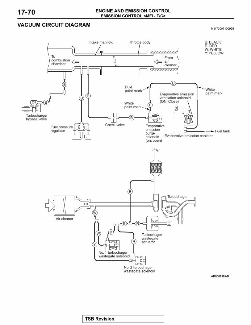
EMISSION CONTROL <MFI - T/C>ENGINE AND EMISSION CONTROL17-70
VACUUM CIRCUIT DIAGRAMM1173007100995
AK900299AB
Evaporative emission purge solenoid(on: open)
Check valveFuel pressureregulator
Turbocharger bypass valve
B
BB
B
B
B
B
B: BLACKR: REDW: WHITEY: YELLOW
Intake manifold
Fromaircleaner
Tocombustionchamber
Throttle body
Evaporative emission ventilation solenoid (ON: Close)
Evaporative emission canister
Turbochager
Turbochagerwastegateactuator
No. 2 turbochagerwastegate solenoid
No. 1 turbochagerwastegate solenoid
Air cleaner
Fuel tank
R
B
B
B
W
W
YR
Whitepaint mark
Bulepaint mark
Whitepaint mark
TSB Revision
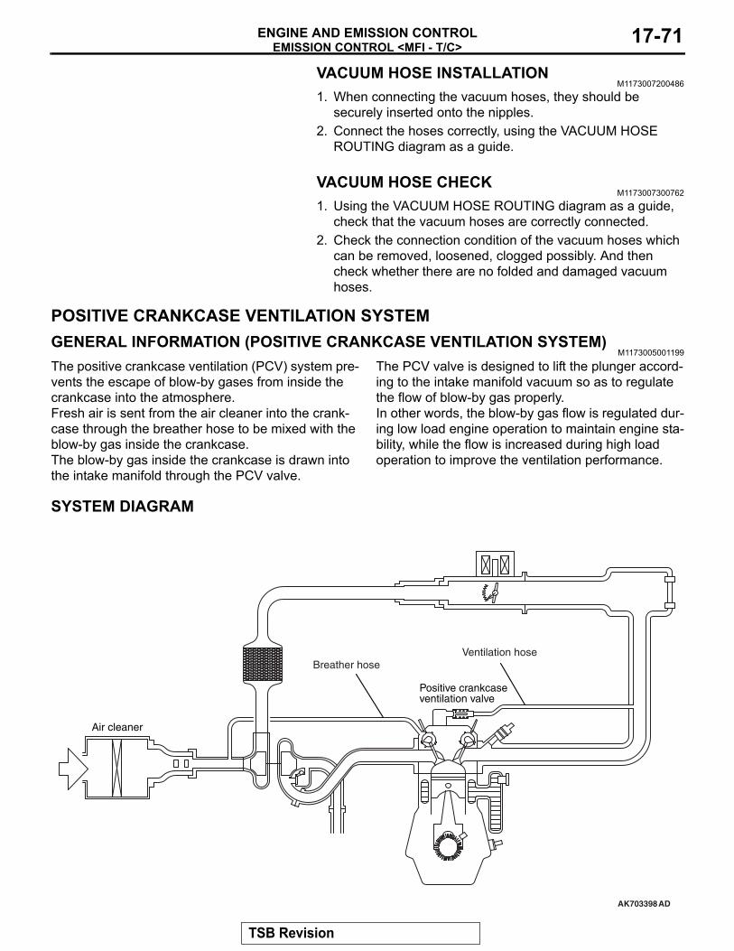
EMISSION CONTROL <MFI - T/C>ENGINE AND EMISSION CONTROL 17-71
VACUUM HOSE INSTALLATIONM1173007200486
1. When connecting the vacuum hoses, they should be securely inserted onto the nipples.
2. Connect the hoses correctly, using the VACUUM HOSE ROUTING diagram as a guide.
VACUUM HOSE CHECKM1173007300762
1. Using the VACUUM HOSE ROUTING diagram as a guide, check that the vacuum hoses are correctly connected.
2. Check the connection condition of the vacuum hoses which can be removed, loosened, clogged possibly. And then check whether there are no folded and damaged vacuum hoses.
POSITIVE CRANKCASE VENTILATION SYSTEMGENERAL INFORMATION (POSITIVE CRANKCASE VENTILATION SYSTEM)
M1173005001199
The positive crankcase ventilation (PCV) system pre-vents the escape of blow-by gases from inside the crankcase into the atmosphere.Fresh air is sent from the air cleaner into the crank-case through the breather hose to be mixed with the blow-by gas inside the crankcase.The blow-by gas inside the crankcase is drawn into the intake manifold through the PCV valve.
The PCV valve is designed to lift the plunger accord-ing to the intake manifold vacuum so as to regulate the flow of blow-by gas properly.In other words, the blow-by gas flow is regulated dur-ing low load engine operation to maintain engine sta-bility, while the flow is increased during high load operation to improve the ventilation performance.
SYSTEM DIAGRAM
AK703398AD
Air cleaner
Positive crankcaseventilation valve
Ventilation hoseBreather hose
TSB Revision
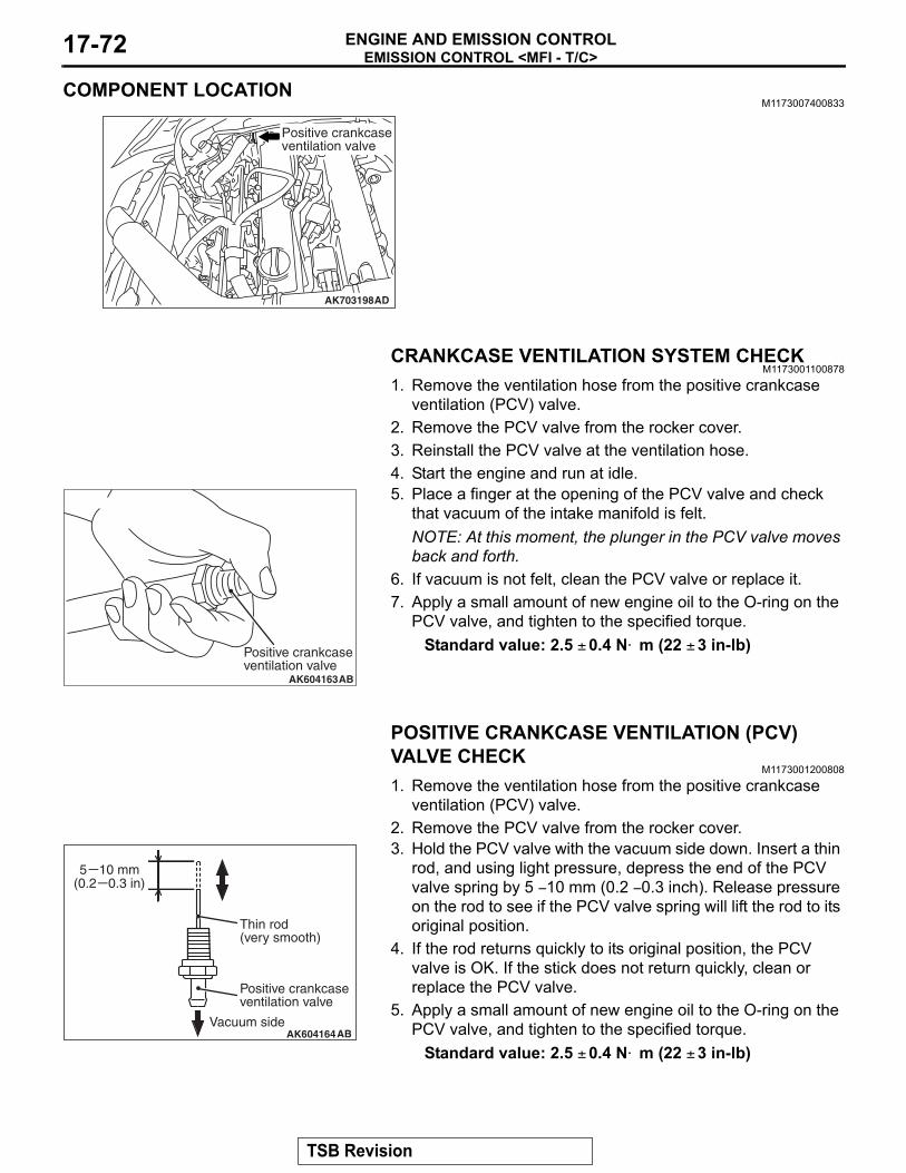
EMISSION CONTROL <MFI - T/C>ENGINE AND EMISSION CONTROL17-72
COMPONENT LOCATIONM1173007400833
CRANKCASE VENTILATION SYSTEM CHECKM1173001100878
1. Remove the ventilation hose from the positive crankcase ventilation (PCV) valve.
2. Remove the PCV valve from the rocker cover.3. Reinstall the PCV valve at the ventilation hose.4. Start the engine and run at idle.5. Place a finger at the opening of the PCV valve and check
that vacuum of the intake manifold is felt.NOTE: At this moment, the plunger in the PCV valve moves back and forth.
6. If vacuum is not felt, clean the PCV valve or replace it.7. Apply a small amount of new engine oil to the O-ring on the
PCV valve, and tighten to the specified torque. Standard value: 2.5 ± 0.4 N⋅ m (22 ± 3 in-lb)
POSITIVE CRANKCASE VENTILATION (PCV) VALVE CHECK
M1173001200808
1. Remove the ventilation hose from the positive crankcase ventilation (PCV) valve.
2. Remove the PCV valve from the rocker cover.3. Hold the PCV valve with the vacuum side down. Insert a thin
rod, and using light pressure, depress the end of the PCV valve spring by 5 − 10 mm (0.2 − 0.3 inch). Release pressure on the rod to see if the PCV valve spring will lift the rod to its original position.
4. If the rod returns quickly to its original position, the PCV valve is OK. If the stick does not return quickly, clean or replace the PCV valve.
5. Apply a small amount of new engine oil to the O-ring on the PCV valve, and tighten to the specified torque.
Standard value: 2.5 ± 0.4 N⋅ m (22 ± 3 in-lb)
AK703198AD
Positive crankcaseventilation valve
AK604163
Positive crankcase ventilation valve
AB
AK604164
Positive crankcase ventilation valve
Thin rod (very smooth)
5 10 mm(0.2 0.3 in)
Vacuum sideAB
TSB Revision
EMISSION CONTROL <MFI - T/C>ENGINE AND EMISSION CONTROL 17-73
EVAPORATIVE EMISSION CONTROL SYSTEMGENERAL INFORMATION (EVAPORATIVE EMISSION SYSTEM)
M1173005101732
The evaporative emission (EVAP) system prevents fuel vapors generated in the fuel tank from escaping into the atmosphere.Fuel vapors from the fuel tank flow through the vapor pipe/hose to be stored temporarily in the EVAP can-ister.When the vehicle is in operation, fuel vapors stored in the EVAP canister flow through the EVAP purge solenoid, purge port and intake manifold plenum to the combustion chamber.When the engine coolant temperature is low or when the intake air quantity is small (when the engine is at idle, for example), the engine control module (ECM) brings the EVAP purge solenoid into the OFF state to shut off the fuel vapor flow to the intake manifold ple-num. This ensures driveability when the engine is cold or running under low load and also stabilizes the emission level.
An EVAP ventilation solenoid is provided between the EVAP canister and atmosphere to monitor for OBD-II EVAP leaks. This solenoid is normally OFF. However, it turns ON when monitoring for OBD-II EVAP leaks and shuts off the atmosphere flow to the EVAP canister. Then the fuel tank differential pres-sure sensor monitors the fuel vapor pressure to detect OBD-II EVAP leaks.When the fuel tank inner pressure increases due to the fuel supply, air is released to the atmosphere from the fuel tank through the EVAP canister and air filter. When the inner pressure of the fuel tank decreases, air is supplied to the fuel tank through the air filter and EVAP canister.
TSB Revision
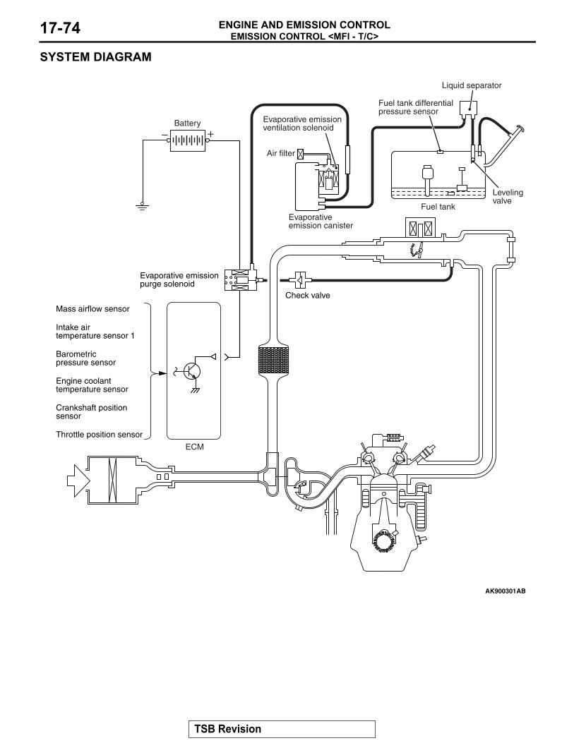
EMISSION CONTROL <MFI - T/C>ENGINE AND EMISSION CONTROL17-74
SYSTEM DIAGRAM
AK900301
Evaporative emissionpurge solenoid
Battery
Check valve
ECM
Mass airflow sensor
Throttle position sensor
Intake airtemperature sensor 1
Barometricpressure sensor
Engine coolanttemperature sensor
Crankshaft positionsensor
AB
Evaporative emission ventilation solenoid
Air filter
Fuel tank differential pressure sensor
Liquid separator
Evaporativeemission canister
Fuel tank
Levelingvalve
TSB Revision
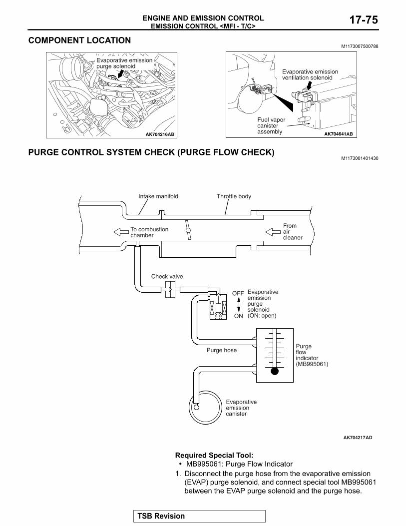
EMISSION CONTROL <MFI - T/C>ENGINE AND EMISSION CONTROL 17-75
COMPONENT LOCATIONM1173007500788
PURGE CONTROL SYSTEM CHECK (PURGE FLOW CHECK)M1173001401430
Required Special Tool:• MB995061: Purge Flow Indicator
1. Disconnect the purge hose from the evaporative emission (EVAP) purge solenoid, and connect special tool MB995061 between the EVAP purge solenoid and the purge hose.
AK704216AB
Evaporative emissionpurge solenoid
AK704641AB
Evaporative emission ventilation solenoid
Fuel vaporcanisterassembly
AK704217AD
Intake manifold Throttle body
To combustionchamber
Check valve
Fromaircleaner
OFF
ON
Purgeflowindicator(MB995061)
Purge hose
Evaporative emission purge solenoid(ON: open)
Evaporativeemissioncanister
TSB Revision
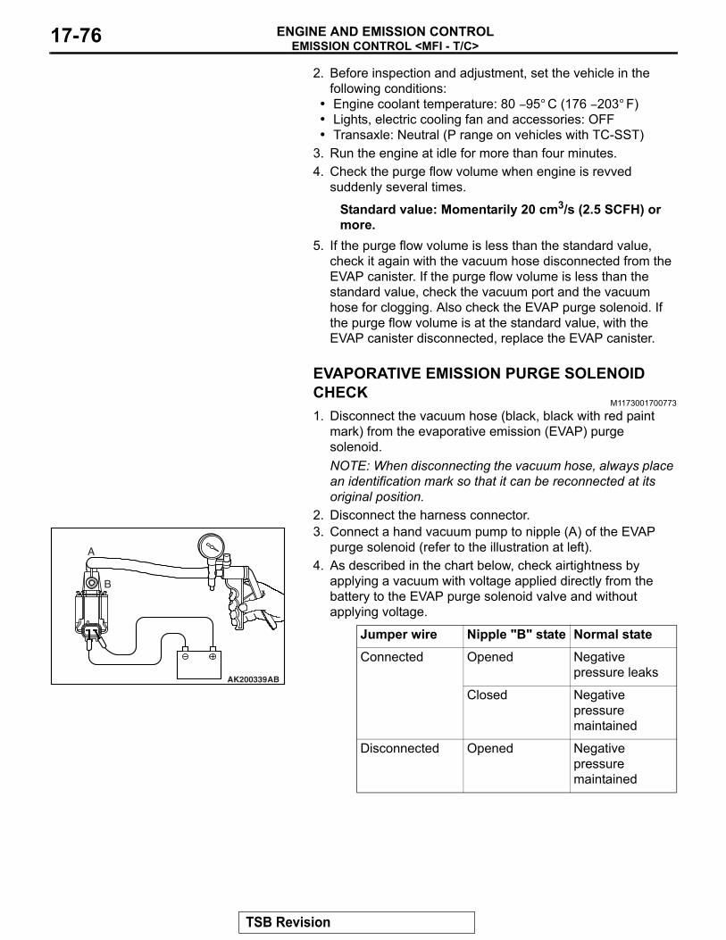
EMISSION CONTROL <MFI - T/C>ENGINE AND EMISSION CONTROL17-76
2. Before inspection and adjustment, set the vehicle in the following conditions:
• Engine coolant temperature: 80 − 95° C (176 − 203° F)• Lights, electric cooling fan and accessories: OFF• Transaxle: Neutral (P range on vehicles with TC-SST)
3. Run the engine at idle for more than four minutes.4. Check the purge flow volume when engine is revved
suddenly several times.
Standard value: Momentarily 20 cm3/s (2.5 SCFH) or more.
5. If the purge flow volume is less than the standard value, check it again with the vacuum hose disconnected from the EVAP canister. If the purge flow volume is less than the standard value, check the vacuum port and the vacuum hose for clogging. Also check the EVAP purge solenoid. If the purge flow volume is at the standard value, with the EVAP canister disconnected, replace the EVAP canister.
EVAPORATIVE EMISSION PURGE SOLENOID CHECK
M1173001700773
1. Disconnect the vacuum hose (black, black with red paint mark) from the evaporative emission (EVAP) purge solenoid.NOTE: When disconnecting the vacuum hose, always place an identification mark so that it can be reconnected at its original position.
2. Disconnect the harness connector.3. Connect a hand vacuum pump to nipple (A) of the EVAP
purge solenoid (refer to the illustration at left).4. As described in the chart below, check airtightness by
applying a vacuum with voltage applied directly from the battery to the EVAP purge solenoid valve and without applying voltage.
Jumper wire Nipple "B" state Normal stateConnected Opened Negative
pressure leaks
Closed Negative pressure maintained
Disconnected Opened Negative pressure maintained
AK200339AB
A
B
TSB Revision
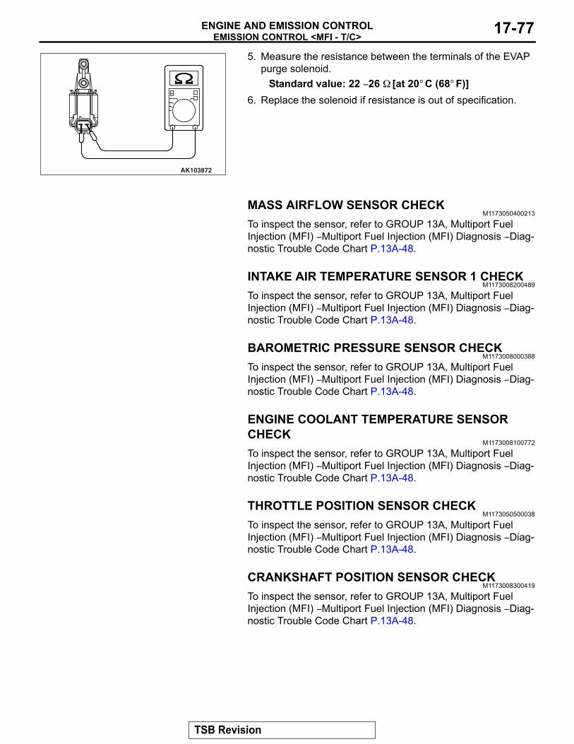
EMISSION CONTROL <MFI - T/C>ENGINE AND EMISSION CONTROL 17-77
5. Measure the resistance between the terminals of the EVAP purge solenoid.
Standard value: 22 − 26 Ω [at 20° C (68° F)]6. Replace the solenoid if resistance is out of specification.
MASS AIRFLOW SENSOR CHECKM1173050400213
To inspect the sensor, refer to GROUP 13A, Multiport Fuel Injection (MFI) − Multiport Fuel Injection (MFI) Diagnosis − Diag-nostic Trouble Code Chart P.13A-48.
INTAKE AIR TEMPERATURE SENSOR 1 CHECKM1173008200489
To inspect the sensor, refer to GROUP 13A, Multiport Fuel Injection (MFI) − Multiport Fuel Injection (MFI) Diagnosis − Diag-nostic Trouble Code Chart P.13A-48.
BAROMETRIC PRESSURE SENSOR CHECKM1173008000388
To inspect the sensor, refer to GROUP 13A, Multiport Fuel Injection (MFI) − Multiport Fuel Injection (MFI) Diagnosis − Diag-nostic Trouble Code Chart P.13A-48.
ENGINE COOLANT TEMPERATURE SENSOR CHECK
M1173008100772
To inspect the sensor, refer to GROUP 13A, Multiport Fuel Injection (MFI) − Multiport Fuel Injection (MFI) Diagnosis − Diag-nostic Trouble Code Chart P.13A-48.
THROTTLE POSITION SENSOR CHECKM1173050500038
To inspect the sensor, refer to GROUP 13A, Multiport Fuel Injection (MFI) − Multiport Fuel Injection (MFI) Diagnosis − Diag-nostic Trouble Code Chart P.13A-48.
CRANKSHAFT POSITION SENSOR CHECKM1173008300419
To inspect the sensor, refer to GROUP 13A, Multiport Fuel Injection (MFI) − Multiport Fuel Injection (MFI) Diagnosis − Diag-nostic Trouble Code Chart P.13A-48.
AK103872
TSB Revision
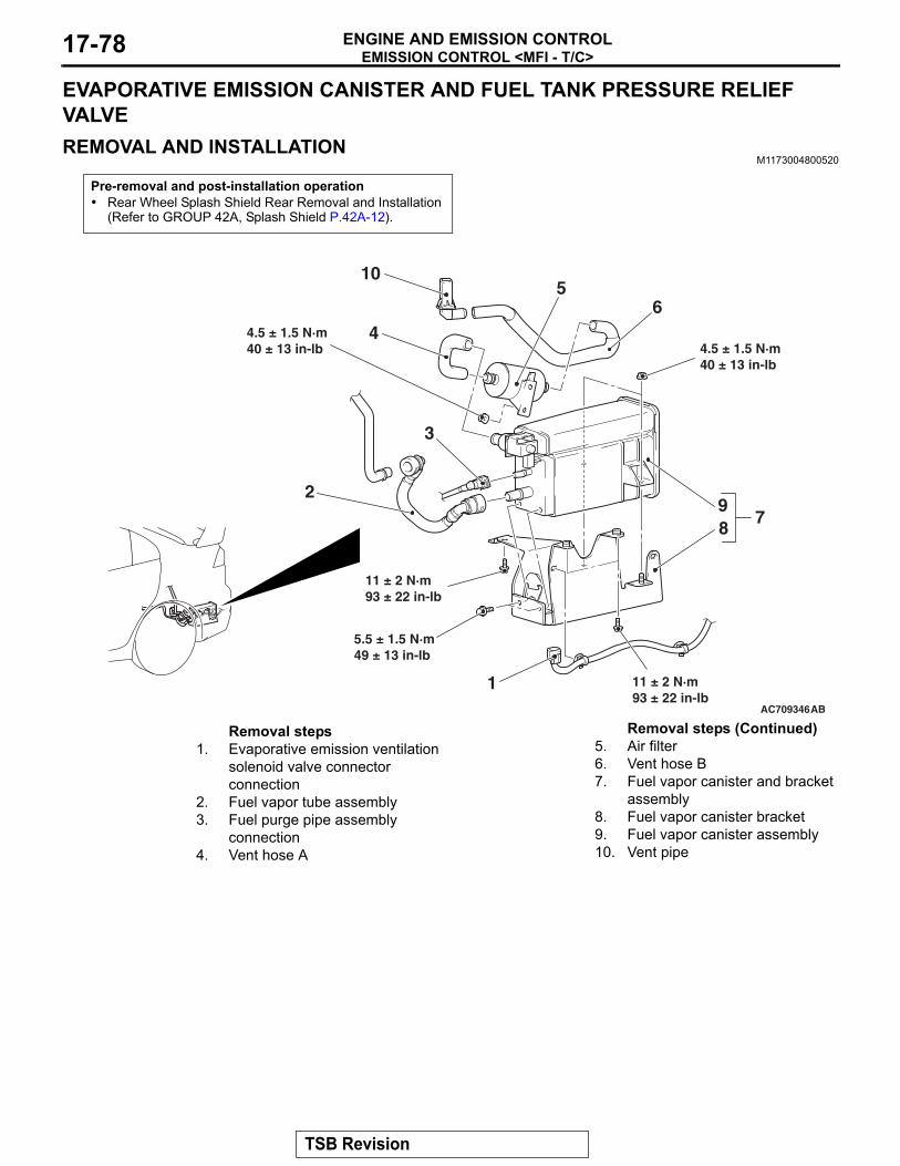
EMISSION CONTROL <MFI - T/C>ENGINE AND EMISSION CONTROL17-78
EVAPORATIVE EMISSION CANISTER AND FUEL TANK PRESSURE RELIEF VALVEREMOVAL AND INSTALLATION
M1173004800520
Pre-removal and post-installation operation• Rear Wheel Splash Shield Rear Removal and Installation
(Refer to GROUP 42A, Splash Shield P.42A-12).
AC709346
4.5 ± 1.5 N·m40 ± 13 in-lb 4.5 ± 1.5 N·m
40 ± 13 in-lb
5.5 ± 1.5 N·m49 ± 13 in-lb
11 ± 2 N·m93 ± 22 in-lb
11 ± 2 N·m93 ± 22 in-lb
1
2
3
4
56
789
10
AB
Removal steps 1. Evaporative emission ventilation
solenoid valve connector connection
2. Fuel vapor tube assembly3. Fuel purge pipe assembly
connection4. Vent hose A
5. Air filter6. Vent hose B7. Fuel vapor canister and bracket
assembly8. Fuel vapor canister bracket9. Fuel vapor canister assembly10. Vent pipe
Removal steps (Continued)
TSB Revision
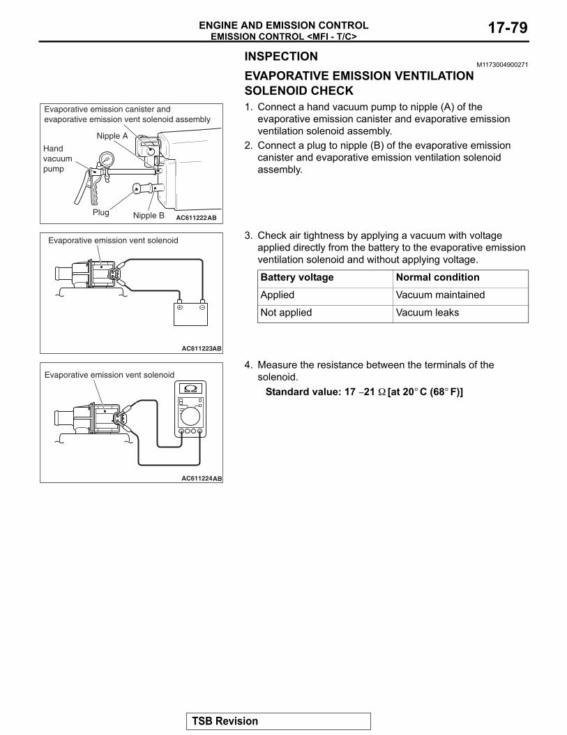
EMISSION CONTROL <MFI - T/C>ENGINE AND EMISSION CONTROL 17-79
INSPECTIONM1173004900271
EVAPORATIVE EMISSION VENTILATION SOLENOID CHECK1. Connect a hand vacuum pump to nipple (A) of the
evaporative emission canister and evaporative emission ventilation solenoid assembly.
2. Connect a plug to nipple (B) of the evaporative emission canister and evaporative emission ventilation solenoid assembly.
3. Check air tightness by applying a vacuum with voltage applied directly from the battery to the evaporative emission ventilation solenoid and without applying voltage.
4. Measure the resistance between the terminals of the solenoid.
Standard value: 17 − 21 Ω [at 20° C (68° F)]
Battery voltage Normal conditionApplied Vacuum maintained
Not applied Vacuum leaks
AC611222
Evaporative emission canister andevaporative emission vent solenoid assembly
Nipple A
Handvacuumpump
Plug Nipple B AB
AC611223
Evaporative emission vent solenoid
AB
AC611224
Evaporative emission vent solenoid
AB
TSB Revision
EMISSION CONTROL <MFI - T/C>ENGINE AND EMISSION CONTROL17-80
CATALYTIC CONVERTERREMOVAL AND INSTALLATION
M1173003901679Refer to GROUP 15, Exhaust Pipe and Main Muffler P.15-26.
TSB Revision