Embed Size (px)
Citation preview
17-1
GROUP 17
ENGINE AND EMISSION CONTROL
CONTENTS
ENGINE CONTROL. . . . . . . . . . 17-3
GENERAL DESCRIPTION . . . . . . 17-3
ENGINE CONTROL SYSTEM DIAGNOSIS . . . . . . . . . . . . . . . . . . 17-3
INTRODUCTION TO ENGINE CONTROL SYSTEM DIAGNOSIS. 17-3
ENGINE CONTROL SYSTEM DIAGNOSTIC TROUBLESHOOTING STRATEGY . . . . . . . . . . . . . . . . . . 17-3
SYMPTOM CHART . . . . . . . . . . . . 17-3
SYMPTOM PROCEDURES. . . . . . 17-3
ON-VEHICLE SERVICE. . . . . . . . . 17-4ACCELERATOR CABLE CHECK AND ADJUSTMENT . . . . . . . . . . . . . . . 17-4
ACCELERATOR CABLE AND PEDAL . . . . . . . . . . . . . . . . . . . . . . 17-5
REMOVAL AND INSTALLATION . . . . . 17-5
EMISSION CONTROL . . . . . . . 17-6
GENERAL DESCRIPTION . . . . . . . 17-6
DIAGNOSIS . . . . . . . . . . . . . . . . . . 17-6
SPECIAL TOOL . . . . . . . . . . . . . . . 17-7
VACUUM HOSES. . . . . . . . . . . . . . 17-8VACUUM HOSE ROUTING . . . . . . . . . . 17-8VACUUM CIRCUIT DIAGRAM. . . . . . . . 17-9VACUUM HOSE INSTALLATION . . . . . 17-9VACUUM HOSE CHECK . . . . . . . . . . . . 17-10
POSITIVE CRANKCASE VENTILATION SYSTEM. . . . . . . . . 17-10
GENERAL DESCRIPTION (POSITIVE CRANKCASE VENTILATION SYSTEM) . . . . . . . . . . . . . . . . . . . . . . . . 17-10COMPONENT LOCATION. . . . . . . . . . . 17-11POSITIVE CRANKCASE VENTILATION SYSTEM CHECK . . . . . . . . . . . . . . . . . . 17-11POSITIVE CRANKCASE VENTILATION VALVE CHECK . . . . . . . . . . . . . . . . . . . 17-11
Continued on next page
17-2
EVAPORATIVE EMISSION CONTROL SYSTEM. . . . . . . . . . . . . . . . . . . . . 17-12
GENERAL DESCRIPTION (EVAPORATIVE EMISSION SYSTEM). 17-12COMPONENT LOCATION . . . . . . . . . . 17-13PURGE CONTROL SYSTEM CHECK (PURGE FLOW CHECK). . . . . . . . . . . . 17-13EVAPORATIVE EMISSION PURGE SOLENOID CHECK. . . . . . . . . . . . . . . . 17-14CHECK VALVE CHECK . . . . . . . . . . . . 17-15VOLUME AIRFLOW SENSOR CHECK. 17-15BAROMETRIC PRESSURE SENSOR CHECK . . . . . . . . . . . . . . . . . . . . . . . . . 17-15ENGINE COOLANT TEMPERATURE SENSOR CHECK . . . . . . . . . . . . . . . . . 17-15INTAKE AIR TEMPERATURE SENSOR CHECK . . . . . . . . . . . . . . . . . 17-15FUEL TANK DIFFERENTIAL PRESSURE SENSOR CHECK . . . . . . . 17-15EVAPORATIVE EMISSION VENTILATION SOLENOID CHECK . . . 17-15
EXHAUST GAS RECIRCULATION (EGR) SYSTEM . . . . . . . . . . . . . . . 17-16
GENERAL DESCRIPTION (EXHAUST GAS RECIRCULATION SYSTEM) . . . . . . . . . . . . . . . . . . . . . . . . 17-16COMPONENT LOCATION . . . . . . . . . . 17-17EGR SYSTEM CHECK . . . . . . . . . . . . . 17-17EGR VALVE CHECK . . . . . . . . . . . . . . . 17-18
EGR PORT VACUUM CHECK. . . . . . . . 17-18EGR VACUUM REGULATOR SOLENOID VALVE CHECK. . . . . . . . . . 17-19VOLUME AIRFLOW SENSOR CHECK . 17-19ENGINE COOLANT TEMPERATURE SENSOR CHECK. . . . . . . . . . . . . . . . . . 17-19CRANKSHAFT POSITION SENSOR CHECK. . . . . . . . . . . . . . . . . . . . . . . . . . 17-20REMOVAL AND INSTALLATION. . . . . . 17-20
EVAPORATIVE EMISSION CANISTER AND FUEL TANK PRESSURE RELIEF VALVE . . . . . 17-21
REMOVAL AND INSTALLATION. . . . . . 17-21INSPECTION . . . . . . . . . . . . . . . . . . . . . 17-22
CATALYTIC CONVERTER . . . . . . 17-24GENERAL DESCRIPTION (CATALYTIC CONVERTER) . . . . . . . . . 17-24REMOVAL AND INSTALLATION. . . . . . 17-24
SPECIFICATIONS . . . . . . . . . . 17-25
FASTENER TIGHTENING SPECIFICATIONS . . . . . . . . . . . . . 17-25
SERVICE SPECIFICATIONS . . . . . 17-26
ENGINE CONTROLENGINE AND EMISSION CONTROL 17-3
ENGINE CONTROLGENERAL DESCRIPTION
M1171000100233A cable-type accelerator mechanical sus-pended-type pedal has been adopted.
ENGINE CONTROL SYSTEM DIAGNOSISINTRODUCTION TO ENGINE CONTROL SYSTEM DIAGNOSIS
M1171002000221If there is a malfunction in the engine control system, the accelerator cable, accelerator pedal or throttle lever may be faulty.
ENGINE CONTROL SYSTEM DIAGNOSTIC TROUBLESHOOTING STRATEGYM1171002100240
Use these steps to plan your diagnostic strategy.If you follow them carefully, you will be sure that you have exhausted most of the possible ways to find an engine control system fault.1. Gather information from the customer.
2. Verify that the condition described by the customer exists.
3. Find the malfunction by following the Symptom Chart.
4. Verify that the malfunction is eliminated.
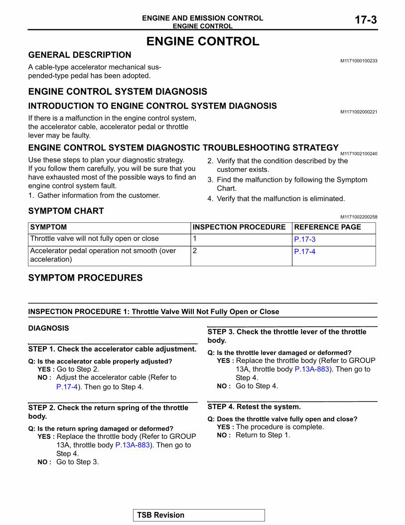
SYMPTOM CHARTM1171002200258
SYMPTOM INSPECTION PROCEDURE REFERENCE PAGEThrottle valve will not fully open or close 1 P.17-3Accelerator pedal operation not smooth (over acceleration)
2 P.17-4
SYMPTOM PROCEDURES
INSPECTION PROCEDURE 1: Throttle Valve Will Not Fully Open or Close
DIAGNOSIS
STEP 1. Check the accelerator cable adjustment.Q: Is the accelerator cable properly adjusted?
YES : Go to Step 2.NO : Adjust the accelerator cable (Refer to
P.17-4). Then go to Step 4.
STEP 2. Check the return spring of the throttle body.Q: Is the return spring damaged or deformed?
YES : Replace the throttle body (Refer to GROUP 13A, throttle body P.13A-883). Then go to Step 4.
NO : Go to Step 3.
STEP 3. Check the throttle lever of the throttle body.Q: Is the throttle lever damaged or deformed?
YES : Replace the throttle body (Refer to GROUP 13A, throttle body P.13A-883). Then go to Step 4.
NO : Go to Step 4.
STEP 4. Retest the system.Q: Does the throttle valve fully open and close?
YES : The procedure is complete.NO : Return to Step 1.
TSB Revision
ENGINE CONTROLENGINE AND EMISSION CONTROL17-4
INSPECTION PROCEDURE 2: Accelerator Pedal Operation not Smooth (Over Acceleration)
DIAGNOSIS
STEP 1. Check the accelerator pedal.Q: Is the accelerator pedal good condition?
YES : Go to Step 2.NO : Replace the accelerator pedal (Refer to
P.17-5). Then go to Step 5.
STEP 2. Check the installation condition of the accelerator pedal.Q: Is the accelerator pedal loose?
YES : Tighten, then go to Step 5.NO : Go to Step 3.
STEP 3. Check the accelerator cable wiring.Q: Is the accelerator cable routing bent sharply?
YES : Repair, then go to Step 5.NO : Go to Step 4.
STEP 4. Check the accelerator cable lubricant.Q: Is the accelerator cable lubricated sufficiently?
YES : Go to Step 5.NO : Refill or replace the lubricant, then go to
Step 5.
STEP 5. Retest the system.Q: Does the accelerator pedal work normally?
YES : The procedure is complete.NO : Return to Step 1.
ON-VEHICLE SERVICE
ACCELERATOR CABLE CHECK AND ADJUSTMENT
M1171000900262
1. Turn off air conditioning and all lights. Inspect and adjust at no load.
2. Start engine and allow to idle unit it reaches normal operating temperature.
3. Confirm the idle speed is at standard value.Standard value: 850 ± 50 r/min
4. Stop the engine [ignition switch in the ''LOCK'' (OFF) position].
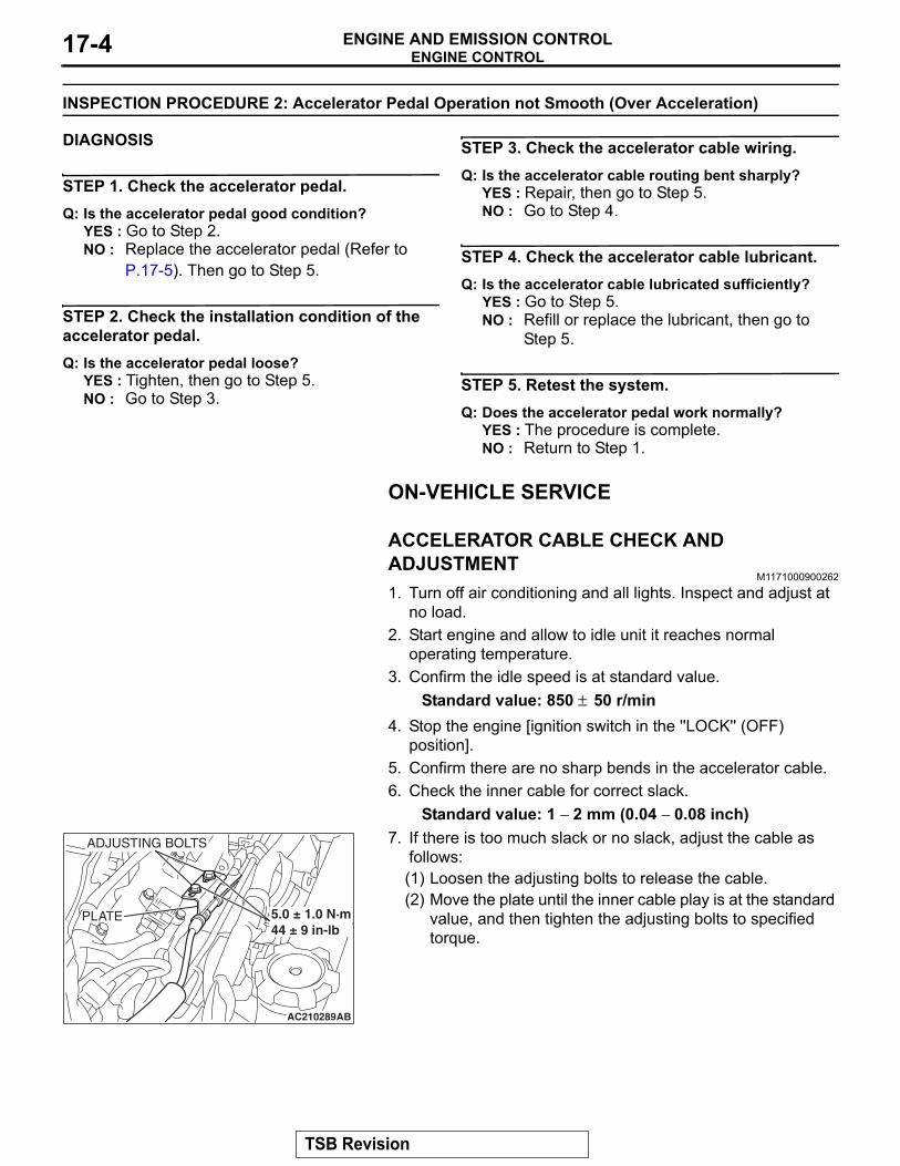
5. Confirm there are no sharp bends in the accelerator cable.6. Check the inner cable for correct slack.
Standard value: 1 − 2 mm (0.04 − 0.08 inch)
AC210289AB
PLATE
ADJUSTING BOLTS
5.0 ± 1.0 N·m44 ± 9 in-lb
7. If there is too much slack or no slack, adjust the cable as follows:(1) Loosen the adjusting bolts to release the cable.(2) Move the plate until the inner cable play is at the standard
value, and then tighten the adjusting bolts to specified torque.
TSB Revision
ENGINE CONTROLENGINE AND EMISSION CONTROL 17-5
ACCELERATOR CABLE AND PEDALREMOVAL AND INSTALLATION
M1171001200307
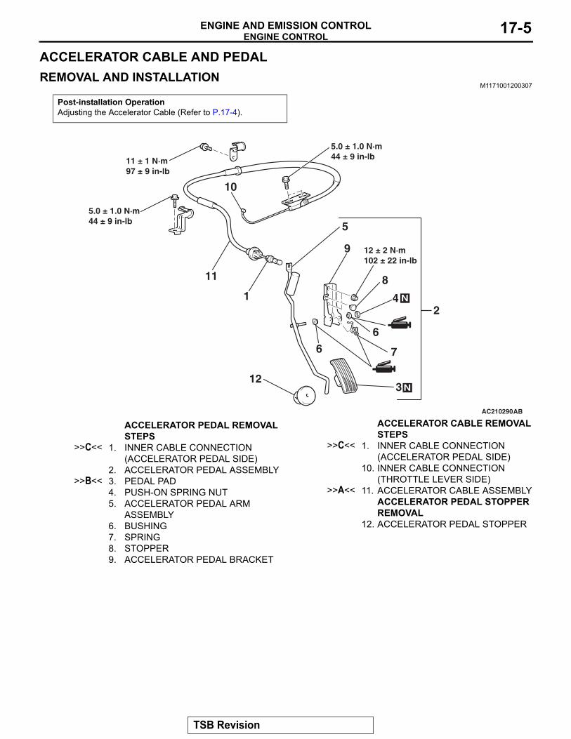
Post-installation OperationAdjusting the Accelerator Cable (Refer to P.17-4).
AC210290AB
1
3
10
4
6
12
7
8
6
2
11
5
9 12 ± 2 N·m102 ± 22 in-lb
5.0 ± 1.0 N·m44 ± 9 in-lb 11 ± 1 N·m
97 ± 9 in-lb
N
N
5.0 ± 1.0 N·m44 ± 9 in-lb
ACCELERATOR PEDAL REMOVAL STEPS
>>C<< 1. INNER CABLE CONNECTION (ACCELERATOR PEDAL SIDE)
2. ACCELERATOR PEDAL ASSEMBLY>>B<< 3. PEDAL PAD
4. PUSH-ON SPRING NUT5. ACCELERATOR PEDAL ARM
ASSEMBLY6. BUSHING7. SPRING8. STOPPER9. ACCELERATOR PEDAL BRACKET
ACCELERATOR CABLE REMOVAL STEPS
>>C<< 1. INNER CABLE CONNECTION (ACCELERATOR PEDAL SIDE)
10. INNER CABLE CONNECTION (THROTTLE LEVER SIDE)
>>A<< 11. ACCELERATOR CABLE ASSEMBLYACCELERATOR PEDAL STOPPER REMOVAL
12. ACCELERATOR PEDAL STOPPER
TSB Revision
EMISSION CONTROLENGINE AND EMISSION CONTROL17-6
INSTALLATION SERVICE POINTS.
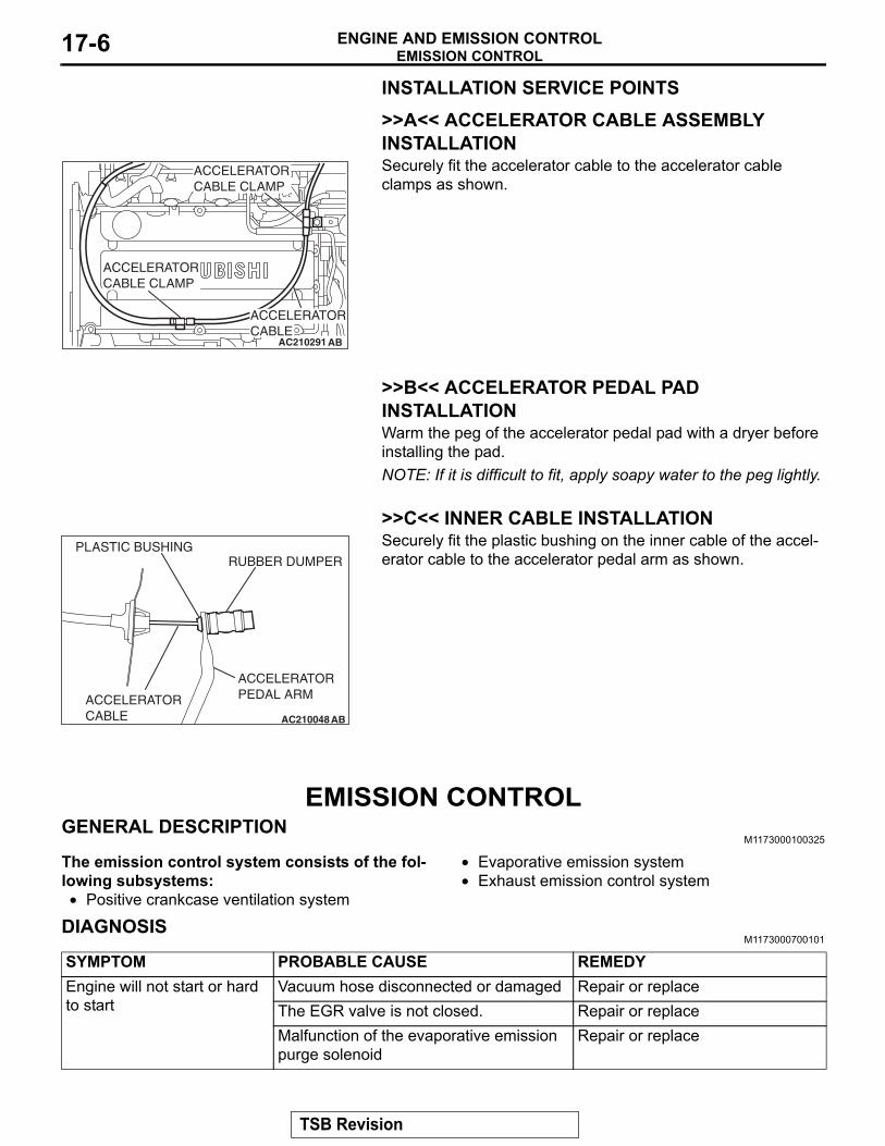
>>A<< ACCELERATOR CABLE ASSEMBLY INSTALLATION
AC210291 AB
ACCELERATORCABLE CLAMP
ACCELERATORCABLE CLAMP
ACCELERATORCABLE
Securely fit the accelerator cable to the accelerator cable clamps as shown.
.
>>B<< ACCELERATOR PEDAL PAD INSTALLATIONWarm the peg of the accelerator pedal pad with a dryer before installing the pad.NOTE: If it is difficult to fit, apply soapy water to the peg lightly..
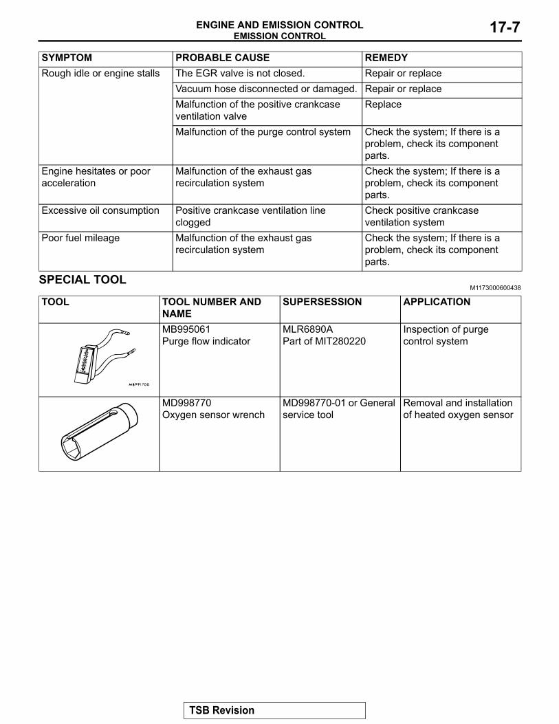
>>C<< INNER CABLE INSTALLATION
AC210048
PLASTIC BUSHING
ACCELERATORCABLE
ACCELERATORPEDAL ARM
RUBBER DUMPER
AB
Securely fit the plastic bushing on the inner cable of the accel-erator cable to the accelerator pedal arm as shown.
EMISSION CONTROLGENERAL DESCRIPTION
M1173000100325
The emission control system consists of the fol-lowing subsystems:• Positive crankcase ventilation system
• Evaporative emission system• Exhaust emission control system
DIAGNOSISM1173000700101
SYMPTOM PROBABLE CAUSE REMEDYEngine will not start or hard to start
Vacuum hose disconnected or damaged Repair or replaceThe EGR valve is not closed. Repair or replaceMalfunction of the evaporative emission purge solenoid
Repair or replace
TSB Revision
EMISSION CONTROLENGINE AND EMISSION CONTROL 17-7
SPECIAL TOOLM1173000600438
TOOL TOOL NUMBER AND NAME
SUPERSESSION APPLICATION
MB995061Purge flow indicator
MLR6890APart of MIT280220
Inspection of purge control system
MD998770 Oxygen sensor wrench
MD998770-01 or General service tool
Removal and installation of heated oxygen sensor
Rough idle or engine stalls The EGR valve is not closed. Repair or replaceVacuum hose disconnected or damaged. Repair or replaceMalfunction of the positive crankcase ventilation valve
Replace
Malfunction of the purge control system Check the system; If there is a problem, check its component parts.
Engine hesitates or poor acceleration
Malfunction of the exhaust gas recirculation system
Check the system; If there is a problem, check its component parts.
Excessive oil consumption Positive crankcase ventilation line clogged
Check positive crankcase ventilation system
Poor fuel mileage Malfunction of the exhaust gas recirculation system
Check the system; If there is a problem, check its component parts.
SYMPTOM PROBABLE CAUSE REMEDY
TSB Revision
EMISSION CONTROLENGINE AND EMISSION CONTROL17-8
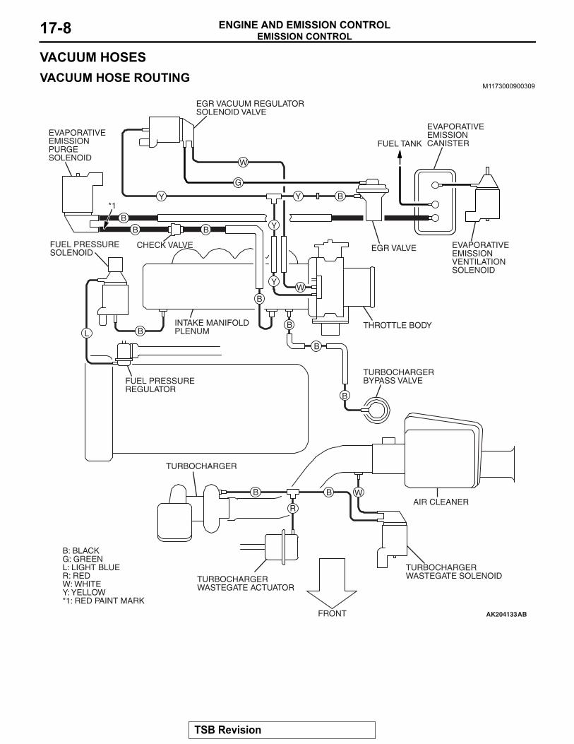
VACUUM HOSESVACUUM HOSE ROUTING
M1173000900309
AK204133
W
W
W
G
Y
Y
Y
Y
BB B
B
BLB
B
B
BB
R
B
EGR VACUUM REGULATORSOLENOID VALVE
EVAPORATIVE EMISSION PURGE SOLENOID
CHECK VALVE
INTAKE MANIFOLDPLENUM
FUEL PRESSURESOLENOID
*1
FUEL PRESSUREREGULATOR
TURBOCHARGER
B: BLACKG: GREENL: LIGHT BLUER: REDW: WHITEY: YELLOW*1: RED PAINT MARK
TURBOCHARGER WASTEGATE ACTUATOR
FRONT
TURBOCHARGER WASTEGATE SOLENOID
TURBOCHARGER BYPASS VALVE
THROTTLE BODY
EGR VALVE
FUEL TANK
EVAPORATIVEEMISSIONCANISTER
EVAPORATIVEEMISSIONVENTILATIONSOLENOID
AIR CLEANER
AB
TSB Revision
EMISSION CONTROLENGINE AND EMISSION CONTROL 17-9
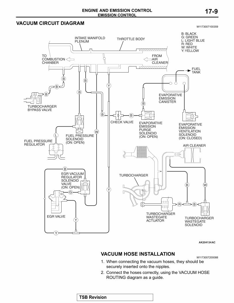
VACUUM CIRCUIT DIAGRAMM1173007100359
AK204134AC
FROMAIR CLEANER
AIR CLEANER
FUELTANK
EVAPORATIVEEMISSIONCANISTER
EVAPORATIVEEMISSIONVENTILATIONSOLENOID(ON: CLOSED)
EVAPORATIVE EMISSION PURGE SOLENOID(ON: OPEN)
CHECK VALVE
TURBOCHARGER WASTEGATE ACTUATOR
TURBOCHARGER
TURBOCHARGER WASTEGATE SOLENOID
EGR VACUUM REGULATORSOLENOID VALVE(ON: OPEN)
EGR VALVE
FUEL PRESSURESOLENOID(ON: OPEN)FUEL PRESSURE
REGULATOR
TURBOCHARGER BYPASS VALVE
TOCOMBUSTIONCHANBER
B
B
BB
B
Y
Y
R B
B W
B B
B
WL
B
G
Y
Y
INTAKE MANIFOLDPLENUM
THROTTLE BODY
B: BLACKG: GREENL: LIGHT BLUER: REDW: WHITEY: YELLOW
VACUUM HOSE INSTALLATIONM1173007200088
1. When connecting the vacuum hoses, they should be securely inserted onto the nipples.
2. Connect the hoses correctly, using the VACUUM HOSE ROUTING diagram as a guide.
TSB Revision
EMISSION CONTROLENGINE AND EMISSION CONTROL17-10
VACUUM HOSE CHECKM1173007300126
1. Using the VACUUM HOSE ROUTING diagram as a guide, check that the vacuum hoses are correctly connected.
2. Check the connection of the vacuum hoses, (removed, loose, etc.) and confirm that there are no sharp bends or damage.
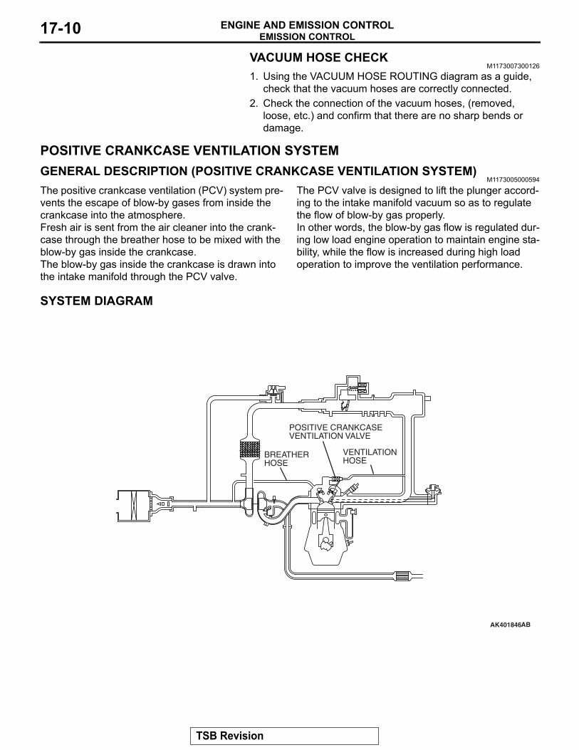
POSITIVE CRANKCASE VENTILATION SYSTEMGENERAL DESCRIPTION (POSITIVE CRANKCASE VENTILATION SYSTEM)
M1173005000594
The positive crankcase ventilation (PCV) system pre-vents the escape of blow-by gases from inside the crankcase into the atmosphere.Fresh air is sent from the air cleaner into the crank-case through the breather hose to be mixed with the blow-by gas inside the crankcase.The blow-by gas inside the crankcase is drawn into the intake manifold through the PCV valve.
The PCV valve is designed to lift the plunger accord-ing to the intake manifold vacuum so as to regulate the flow of blow-by gas properly.In other words, the blow-by gas flow is regulated dur-ing low load engine operation to maintain engine sta-bility, while the flow is increased during high load operation to improve the ventilation performance.
SYSTEM DIAGRAM
AK401846
POSITIVE CRANKCASE VENTILATION VALVE
AB
BREATHERHOSE
VENTILATIONHOSE
TSB Revision
EMISSION CONTROLENGINE AND EMISSION CONTROL 17-11
COMPONENT LOCATIONM1173007400286
AK204135AC
POSITIVE CRANKCASEVENTILATION VALVE
POSITIVE CRANKCASE VENTILATION SYSTEM CHECK
M1173001100232
1. Remove the positive crankcase ventilation (PCV) valve from the rocker cover, then reconnect the PCV valve to the vacuum supply hose.
AK203692
POSITIVE CRANKCASEVENTILATION VALVE
AC
2. With the engine idling, put your finger on the open end of the PCV valve, and check for negative pressure (vacuum).NOTE: At this time, the plunger in the PCV valve should move back and forth as the open end is covered and uncov-ered.
3. If negative pressure is not felt, clean or replace the PCV valve. Inspect the vacuum supply hose and vacuum supply hose port for restriction or plugged condition.
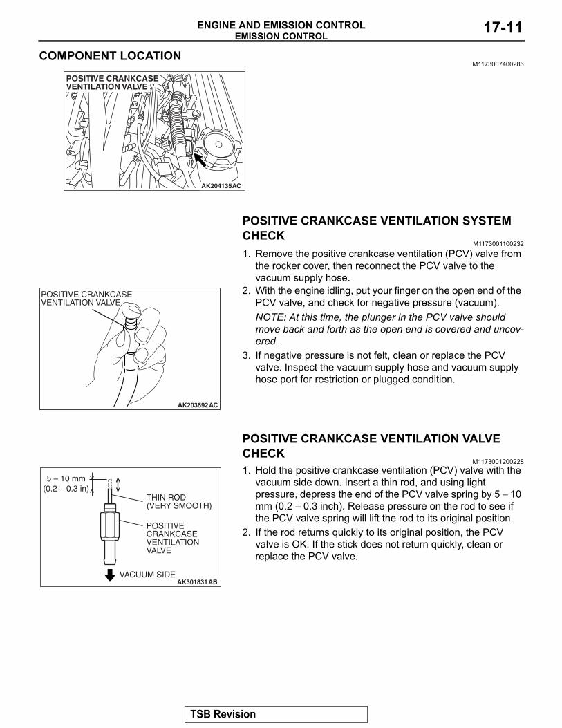
POSITIVE CRANKCASE VENTILATION VALVE CHECK
M1173001200228
AK301831
5 – 10 mm(0.2 – 0.3 in)
THIN ROD(VERY SMOOTH)
POSITIVE CRANKCASE VENTILATION VALVE
VACUUM SIDEAB
1. Hold the positive crankcase ventilation (PCV) valve with the vacuum side down. Insert a thin rod, and using light pressure, depress the end of the PCV valve spring by 5 − 10 mm (0.2 − 0.3 inch). Release pressure on the rod to see if the PCV valve spring will lift the rod to its original position.
2. If the rod returns quickly to its original position, the PCV valve is OK. If the stick does not return quickly, clean or replace the PCV valve.
TSB Revision
EMISSION CONTROLENGINE AND EMISSION CONTROL17-12
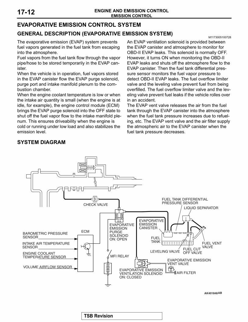
EVAPORATIVE EMISSION CONTROL SYSTEMGENERAL DESCRIPTION (EVAPORATIVE EMISSION SYSTEM)
M1173005100728
The evaporative emission (EVAP) system prevents fuel vapors generated in the fuel tank from escaping into the atmosphere.Fuel vapors from the fuel tank flow through the vapor pipe/hose to be stored temporarily in the EVAP can-ister. When the vehicle is in operation, fuel vapors stored in the EVAP canister flow the EVAP purge solenoid, purge port and intake manifold plenum to the com-bustion chamber.When the engine coolant temperature is low or when the intake air quantity is small (when the engine is at idle, for example), the engine control module (ECM) brings the EVAP purge solenoid into the OFF state to shut off the fuel vapor flow to the intake manifold ple-num. This ensures driveability when the engine is cold or running under low load and also stabilizes the emission level.
An EVAP ventilation solenoid is provided between the EVAP canister and atmosphere to monitor for OBD-II EVAP leaks. This solenoid is normally OFF. However, it turns ON when monitoring the OBD-II EVAP leaks and shuts off the atmosphere flow to the EVAP canister. Then the fuel tank differential pres-sure sensor monitors the fuel vapor pressure to detect OBD-II EVAP leaks. The fuel overflow limiter valve and the leveling valve prevent fuel from being overfilled. The fuel overflow limiter valve and the lev-eling valve prevent fuel leaks if the vehicle rolles over in an accident.The EVAP vent valve releases the air from the fuel tank through the EVAP canister into the atmosphere when the fuel tank pressure increases due to refuel-ing, etc. The EVAP vent valve and the air filter supply the atmospheric air to the EVAP canister when the fuel tank pressure decreases.
SYSTEM DIAGRAM
AK401848
FUEL TANK DIFFERENTIALPRESSURE SENSOR
LIQUID SEPARATOR
EVAPORATIVE EMISSIONCANISTER
EVAPORATIVE EMISSION PURGE SOLENOID ON: OPEN
ECM BAROMETRIC PRESSURE SENSOR
INTAKE AIR TEMPERATURESENSOR
ENGINE COOLANT TEMPERATURE SENSOR
VOLUME AIRFLOW SENSOR
FUELTANK
MFI RELAY
FUEL VENT VALVE
FUEL CUTOFF VALVELEVELING VALVE
EVAPORATIVE EMISSION VENT VALVE
AIR FILTEREVAPORATIVE EMISSION VENTILATION SOLENOIDON: CLOSED
AB
CHECK VALVE
TSB Revision
EMISSION CONTROLENGINE AND EMISSION CONTROL 17-13
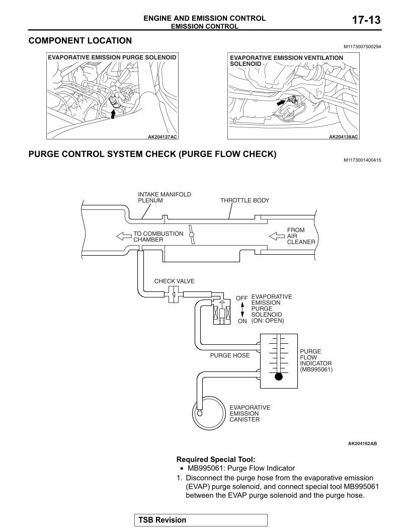
COMPONENT LOCATIONM1173007500294
AK204137
EVAPORATIVE EMISSION PURGE SOLENOID
AC AK204138AC
EVAPORATIVE EMISSION VENTILATIONSOLENOID
PURGE CONTROL SYSTEM CHECK (PURGE FLOW CHECK)M1173001400415
AK204162
INTAKE MANIFOLDPLENUM THROTTLE BODY
TO COMBUSTIONCHAMBER
CHECK VALVE
FROMAIRCLEANER
OFF
ON
PURGEFLOWINDICATOR(MB995061)
PURGE HOSE
EVAPORATIVE EMISSION PURGE SOLENOID(ON: OPEN)
EVAPORATIVEEMISSIONCANISTER
AB
Required Special Tool:• MB995061: Purge Flow Indicator
1. Disconnect the purge hose from the evaporative emission (EVAP) purge solenoid, and connect special tool MB995061 between the EVAP purge solenoid and the purge hose.
TSB Revision
EMISSION CONTROLENGINE AND EMISSION CONTROL17-14
2. Before inspection and adjustment, set the vehicle in the following conditions:
• Engine coolant temperature: 80 − 95° C (176 − 203° F)• Lights, electric cooling fan and accessories: OFF• Transaxle: Neutral
3. Run the engine at idle for more than four minutes.4. Check the purge flow volume when engine is revved
suddenly several times.
Standard value: Momentarily 20 cm3/s (2.5 SCFH) or more.
5. If the purge flow volume is less than the standard value, check it again with the vacuum hose disconnected from the EVAP canister. If the purge flow volume is less than the standard value, check the vacuum port and the vacuum hose for clogging. Also check the EVAP purge solenoid. If the purge flow volume is at the standard value, with the EVAP canister disconnected, replace the EVAP canister.
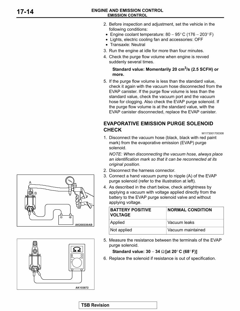
EVAPORATIVE EMISSION PURGE SOLENOID CHECK
M1173001700308
1. Disconnect the vacuum hose (black, black with red paint mark) from the evaporative emission (EVAP) purge solenoid.NOTE: When disconnecting the vacuum hose, always place an identification mark so that it can be reconnected at its original position.
2. Disconnect the harness connector.
AK200339AB
A
B
3. Connect a hand vacuum pump to nipple (A) of the EVAP purge solenoid (refer to the illustration at left).
4. As described in the chart below, check airtightness by applying a vacuum with voltage applied directly from the battery to the EVAP purge solenoid valve and without applying voltage.
BATTERY POSITIVE VOLTAGE
NORMAL CONDITION
Applied Vacuum leaks
Not applied Vacuum maintained
AK103872
5. Measure the resistance between the terminals of the EVAP purge solenoid.
Standard value: 30 − 34 Ω [at 20° C (68° F)]6. Replace the solenoid if resistance is out of specification.
TSB Revision
EMISSION CONTROLENGINE AND EMISSION CONTROL 17-15
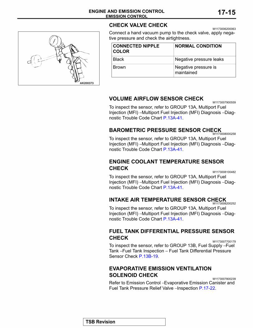
CHECK VALVE CHECKM1173006200063
AK200373
Connect a hand vacuum pump to the check valve, apply nega-tive pressure and check the airtightness.
CONNECTED NIPPLE COLOR
NORMAL CONDITION
Black Negative pressure leaks
Brown Negative pressure is maintained
VOLUME AIRFLOW SENSOR CHECKM1173007900559
To inspect the sensor, refer to GROUP 13A, Multiport Fuel Injection (MFI) − Multiport Fuel Injection (MFI) Diagnosis − Diag-nostic Trouble Code Chart P.13A-41.
BAROMETRIC PRESSURE SENSOR CHECKM1173008000258
To inspect the sensor, refer to GROUP 13A, Multiport Fuel Injection (MFI) − Multiport Fuel Injection (MFI) Diagnosis − Diag-nostic Trouble Code Chart P.13A-41.
ENGINE COOLANT TEMPERATURE SENSOR CHECK
M1173008100482
To inspect the sensor, refer to GROUP 13A, Multiport Fuel Injection (MFI) − Multiport Fuel Injection (MFI) Diagnosis − Diag-nostic Trouble Code Chart P.13A-41.
INTAKE AIR TEMPERATURE SENSOR CHECKM1173008200252
To inspect the sensor, refer to GROUP 13A, Multiport Fuel Injection (MFI) − Multiport Fuel Injection (MFI) Diagnosis − Diag-nostic Trouble Code Chart P.13A-41.
FUEL TANK DIFFERENTIAL PRESSURE SENSOR CHECK
M1173007700179To inspect the sensor, refer to GROUP 13B, Fuel Supply − Fuel Tank − Fuel Tank Inspection − Fuel Tank Differential Pressure Sensor Check P.13B-19.
EVAPORATIVE EMISSION VENTILATION SOLENOID CHECK
M1173007800239Refer to Emission Control − Evaporative Emission Canister and Fuel Tank Pressure Relief Valve − Inspection P.17-22.
TSB Revision
EMISSION CONTROLENGINE AND EMISSION CONTROL17-16
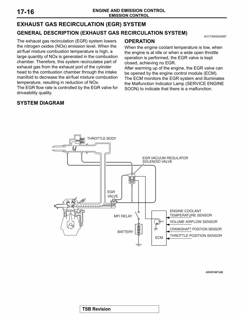
EXHAUST GAS RECIRCULATION (EGR) SYSTEMGENERAL DESCRIPTION (EXHAUST GAS RECIRCULATION SYSTEM)
M1173005200587
The exhaust gas recirculation (EGR) system lowers the nitrogen oxides (NOx) emission level. When the air/fuel mixture combustion temperature is high, a large quantity of NOx is generated in the combustion chamber. Therefore, this system recirculates part of exhaust gas from the exhaust port of the cylinder head to the combustion chamber through the intake manifold to decrease the air/fuel mixture combustion temperature, resulting in reduction of NOx.The EGR flow rate is controlled by the EGR valve for driveability quality.
OPERATIONWhen the engine coolant temperature is low, when the engine is at idle or when a wide open throttle operation is performed, the EGR valve is kept closed, achieving no EGR.After warming up of the engine, the EGR valve can be opened by the engine control module (ECM).The ECM monitors the EGR system and illuminates the Malfunction Indicator Lamp (SERVICE ENGINE SOON) to indicate that there is a malfunction.
SYSTEM DIAGRAM
AK401847
VOLUME AIRFLOW SENSOR
BATTERY
MFI RELAY
ENGINE COOLANTTEMPERATURE SENSOR
CRANKSHAFT POSITION SENSOR
THROTTLE POSITION SENSORECM
AB
EGR VACUUM REGULATORSOLENOID VALVE
EGRVALVE
THROTTLE BODY
TSB Revision
EMISSION CONTROLENGINE AND EMISSION CONTROL 17-17
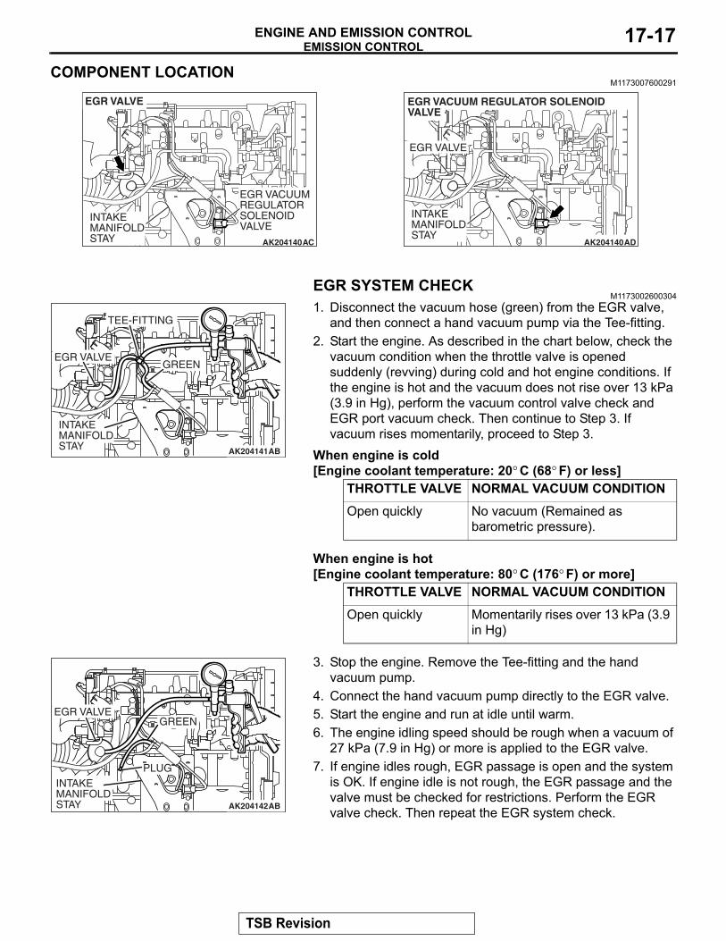
COMPONENT LOCATIONM1173007600291
AK204140 AC
EGR VACUUMREGULATORSOLENOIDVALVE
INTAKEMANIFOLDSTAY
EGR VALVE
AK204140 AD
EGR VACUUM REGULATOR SOLENOID VALVE
INTAKEMANIFOLDSTAY
EGR VALVE
EGR SYSTEM CHECKM1173002600304
AK204141
INTAKEMANIFOLDSTAY AB
EGR VALVE
TEE-FITTING
GREEN
1. Disconnect the vacuum hose (green) from the EGR valve, and then connect a hand vacuum pump via the Tee-fitting.
2. Start the engine. As described in the chart below, check the vacuum condition when the throttle valve is opened suddenly (revving) during cold and hot engine conditions. If the engine is hot and the vacuum does not rise over 13 kPa (3.9 in Hg), perform the vacuum control valve check and EGR port vacuum check. Then continue to Step 3. If vacuum rises momentarily, proceed to Step 3.
When engine is cold [Engine coolant temperature: 20° C (68° F) or less]
THROTTLE VALVE NORMAL VACUUM CONDITIONOpen quickly No vacuum (Remained as
barometric pressure).
When engine is hot [Engine coolant temperature: 80° C (176° F) or more]
THROTTLE VALVE NORMAL VACUUM CONDITIONOpen quickly Momentarily rises over 13 kPa (3.9
in Hg)
AK204142AB
EGR VALVE
PLUG
GREEN
INTAKE MANIFOLD STAY
3. Stop the engine. Remove the Tee-fitting and the hand vacuum pump.
4. Connect the hand vacuum pump directly to the EGR valve.5. Start the engine and run at idle until warm.6. The engine idling speed should be rough when a vacuum of
27 kPa (7.9 in Hg) or more is applied to the EGR valve.7. If engine idles rough, EGR passage is open and the system
is OK. If engine idle is not rough, the EGR passage and the valve must be checked for restrictions. Perform the EGR valve check. Then repeat the EGR system check.
TSB Revision
EMISSION CONTROLENGINE AND EMISSION CONTROL17-18
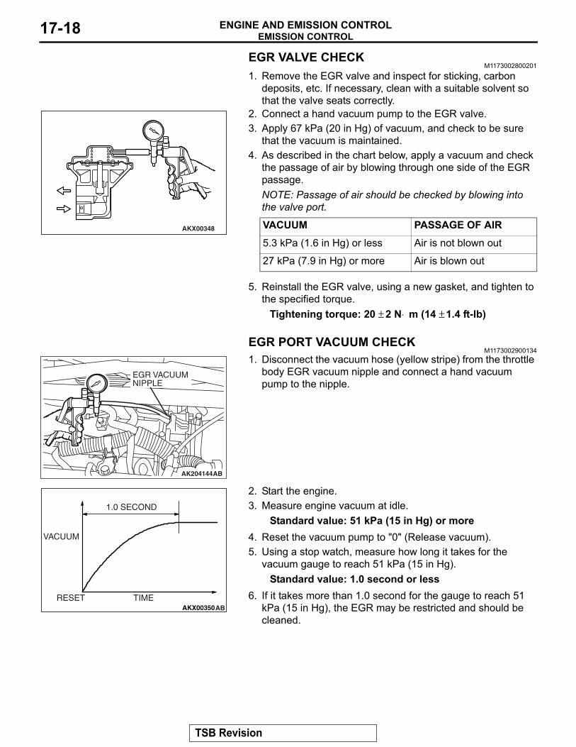
EGR VALVE CHECKM1173002800201
1. Remove the EGR valve and inspect for sticking, carbon deposits, etc. If necessary, clean with a suitable solvent so that the valve seats correctly.
AKX00348
2. Connect a hand vacuum pump to the EGR valve.3. Apply 67 kPa (20 in Hg) of vacuum, and check to be sure
that the vacuum is maintained.4. As described in the chart below, apply a vacuum and check
the passage of air by blowing through one side of the EGR passage.NOTE: Passage of air should be checked by blowing into the valve port.
VACUUM PASSAGE OF AIR5.3 kPa (1.6 in Hg) or less Air is not blown out
27 kPa (7.9 in Hg) or more Air is blown out
5. Reinstall the EGR valve, using a new gasket, and tighten to the specified torque.
Tightening torque: 20 ± 2 N⋅ m (14 ± 1.4 ft-lb)
EGR PORT VACUUM CHECKM1173002900134
AK204144AB
EGR VACUUMNIPPLE
1. Disconnect the vacuum hose (yellow stripe) from the throttle body EGR vacuum nipple and connect a hand vacuum pump to the nipple.
AKX00350
1.0 SECOND
VACUUM
RESET TIMEAB
2. Start the engine.3. Measure engine vacuum at idle.
Standard value: 51 kPa (15 in Hg) or more4. Reset the vacuum pump to "0" (Release vacuum).5. Using a stop watch, measure how long it takes for the
vacuum gauge to reach 51 kPa (15 in Hg).Standard value: 1.0 second or less
6. If it takes more than 1.0 second for the gauge to reach 51 kPa (15 in Hg), the EGR may be restricted and should be cleaned.
TSB Revision
EMISSION CONTROLENGINE AND EMISSION CONTROL 17-19
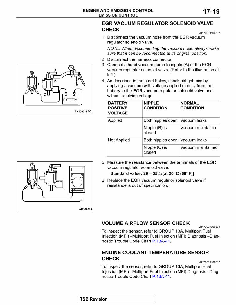
EGR VACUUM REGULATOR SOLENOID VALVE CHECK
M1173003100302
1. Disconnect the vacuum hose from the EGR vacuum regulator solenoid valve.NOTE: When disconnecting the vacuum hose, always make sure that it can be reconnected at its original position.
2. Disconnect the harness connector.
AK100015
B
A
C
AC
BATTERY
3. Connect a hand vacuum pump to nipple (A) of the EGR vacuum regulator solenoid valve. (Refer to the illustration at left.)
4. As described in the chart below, check airtightness by applying a vacuum with voltage applied directly from the battery to the EGR vacuum regulator solenoid valve and without applying voltage.
BATTERY POSITIVE VOLTAGE
NIPPLE CONDITION
NORMAL CONDITION
Applied Both nipples open Vacuum leaks
Nipple (B) is closed
Vacuum maintained
Not Applied Both nipples open Vacuum leaks
Nipple (C) is closed
Vacuum maintained
AK100016
5. Measure the resistance between the terminals of the EGR vacuum regulator solenoid valve.
Standard value: 29 − 35 Ω [at 20° C (68° F)]6. Replace the EGR vacuum regulator solenoid valve if
resistance is out of specification.
VOLUME AIRFLOW SENSOR CHECKM1173007900560
To inspect the sensor, refer to GROUP 13A, Multiport Fuel Injection (MFI) − Multiport Fuel Injection (MFI) Diagnosis − Diag-nostic Trouble Code Chart P.13A-41.
ENGINE COOLANT TEMPERATURE SENSOR CHECK
M1173008100512
To inspect the sensor, refer to GROUP 13A, Multiport Fuel Injection (MFI) − Multiport Fuel Injection (MFI) Diagnosis − Diag-nostic Trouble Code Chart P.13A-41.
TSB Revision
EMISSION CONTROLENGINE AND EMISSION CONTROL17-20
CRANKSHAFT POSITION SENSOR CHECKM1173008300260
To inspect the sensor, refer to GROUP 13A, Multiport Fuel Injection (MFI) − Multiport Fuel Injection (MFI) Diagnosis − Diag-nostic Trouble Code Chart P.13A-41.
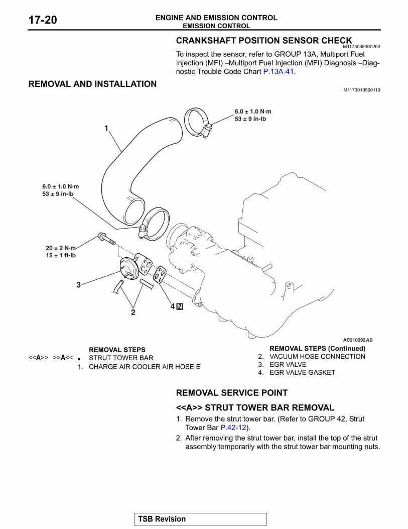
REMOVAL AND INSTALLATIONM1173010500119
AC210292AB
1
3
42
6.0 ± 1.0 N·m53 ± 9 in-lb
N
20 ± 2 N·m15 ± 1 ft-lb
6.0 ± 1.0 N·m53 ± 9 in-lb
REMOVAL STEPS <<A>> >>A<< • STRUT TOWER BAR
1. CHARGE AIR COOLER AIR HOSE E2. VACUUM HOSE CONNECTION3. EGR VALVE4. EGR VALVE GASKET
REMOVAL SERVICE POINT.
<<A>> STRUT TOWER BAR REMOVAL1. Remove the strut tower bar. (Refer to GROUP 42, Strut
Tower Bar P.42-12).2. After removing the strut tower bar, install the top of the strut
assembly temporarily with the strut tower bar mounting nuts.
REMOVAL STEPS (Continued)
TSB Revision
EMISSION CONTROLENGINE AND EMISSION CONTROL 17-21
INSTALLATION SERVICE POINTS.
>>A<< STRUT TOWER BAR INSTALLATION1. Remove the nuts that are temporarily securing the strut
assembly.2. Install the strut tower bar. (Refer to GROUP 42, Strut Tower
Bar P.42-12).
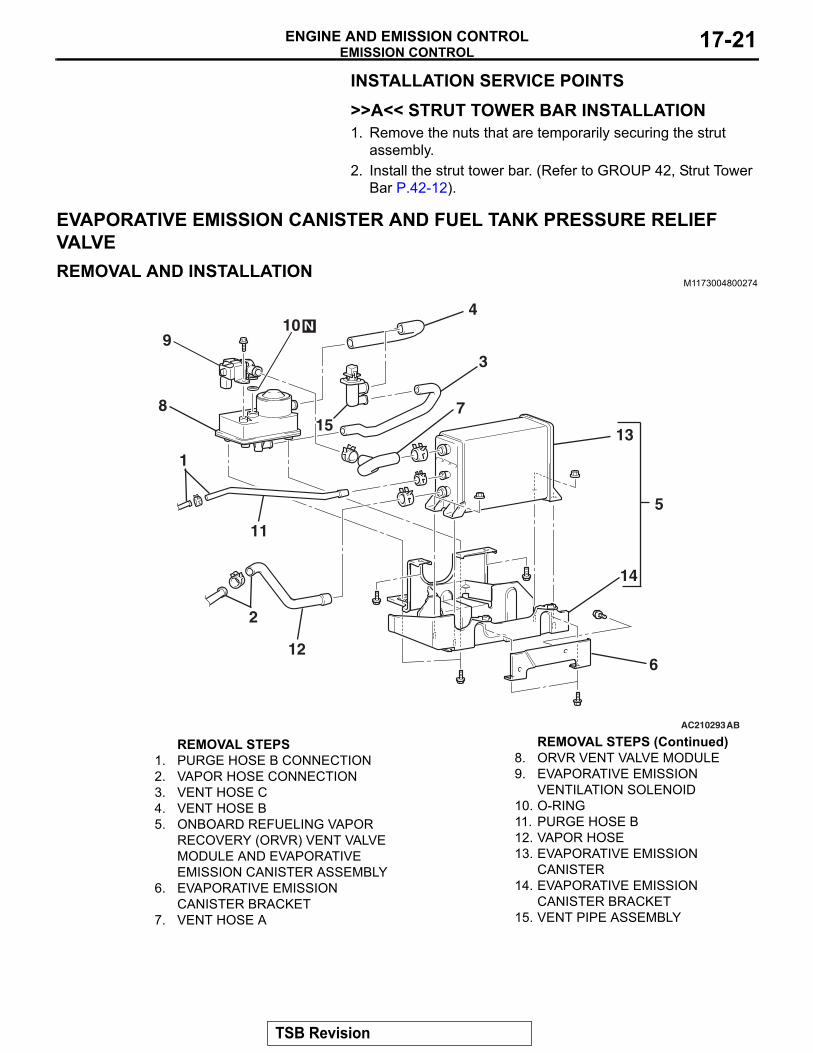
EVAPORATIVE EMISSION CANISTER AND FUEL TANK PRESSURE RELIEF VALVEREMOVAL AND INSTALLATION
M1173004800274
AC210293
5
14
13
12
2
11
1
815
3
7
4
9
6
10 N
AB
REMOVAL STEPS 1. PURGE HOSE B CONNECTION2. VAPOR HOSE CONNECTION3. VENT HOSE C4. VENT HOSE B5. ONBOARD REFUELING VAPOR
RECOVERY (ORVR) VENT VALVE MODULE AND EVAPORATIVE EMISSION CANISTER ASSEMBLY
6. EVAPORATIVE EMISSION CANISTER BRACKET
7. VENT HOSE A
8. ORVR VENT VALVE MODULE9. EVAPORATIVE EMISSION
VENTILATION SOLENOID10. O-RING11. PURGE HOSE B12. VAPOR HOSE13. EVAPORATIVE EMISSION
CANISTER14. EVAPORATIVE EMISSION
CANISTER BRACKET15. VENT PIPE ASSEMBLY
REMOVAL STEPS (Continued)
TSB Revision
EMISSION CONTROLENGINE AND EMISSION CONTROL17-22
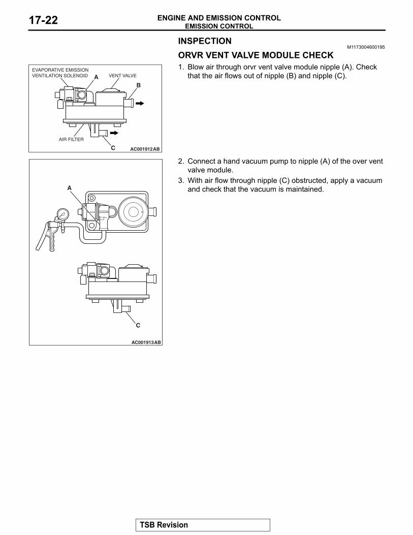
INSPECTIONM1173004600195
ORVR VENT VALVE MODULE CHECK
AC001912AB
AB
C
EVAPORATIVE EMISSIONVENTILATION SOLENOID
AIR FILTER
VENT VALVE
1. Blow air through orvr vent valve module nipple (A). Check that the air flows out of nipple (B) and nipple (C).
AC001913AB
A
C
2. Connect a hand vacuum pump to nipple (A) of the over vent valve module.
3. With air flow through nipple (C) obstructed, apply a vacuum and check that the vacuum is maintained.
TSB Revision
EMISSION CONTROLENGINE AND EMISSION CONTROL 17-23
AC001914
A
AB
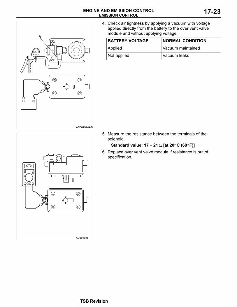
4. Check air tightness by applying a vacuum with voltage applied directly from the battery to the over vent valve module and without applying voltage.
BATTERY VOLTAGE NORMAL CONDITIONApplied Vacuum maintained
Not applied Vacuum leaks
AC001915
5. Measure the resistance between the terminals of the solenoid.
Standard value: 17 − 21 Ω [at 20° C (68° F)]6. Replace over vent valve module if resistance is out of
specification.
TSB Revision
EMISSION CONTROLENGINE AND EMISSION CONTROL17-24
CATALYTIC CONVERTERGENERAL DESCRIPTION (CATALYTIC CONVERTER)
M1173005300131The three way catalytic converter, together with the closed loop air-fuel ratio control based on the oxygen sensor signal, oxidizes carbon monoxides (CO) and hydrocarbons (HC), also reduces nitrogen oxides (NOx).
When the mixture is controlled at stoichiometric air-fuel ratio, the three way catalytic converter pro-vides the highest purification against the three con-stituents, namely, CO, HC and NOx.
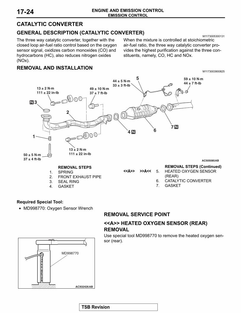
REMOVAL AND INSTALLATIONM1173003900825
AC505085
3
50 ± 5 N·m37 ± 4 ft-lb
49 ± 10 N·m37 ± 7 ft-lb
2
N
13 ± 2 N·m111 ± 22 in-lb
13 ± 2 N·m111 ± 22 in-lb
N
59 ± 10 N·m44 ± 7 ft-lb
1
N
AB
4
5
67
44 ± 5 N·m33 ± 3 ft-lb
REMOVAL STEPS 1. SPRING2. FRONT EXHAUST PIPE 3. SEAL RING4. GASKET
<<A>> >>A<< 5. HEATED OXYGEN SENSOR (REAR)
6. CATALYTIC CONVERTER7. GASKET
Required Special Tool:• MD998770: Oxygen Sensor Wrench
REMOVAL SERVICE POINT.
<<A>> HEATED OXYGEN SENSOR (REAR) REMOVAL
ACX02426AB
MD998770
Use special tool MD998770 to remove the heated oxygen sen-sor (rear).
REMOVAL STEPS (Continued)
TSB Revision
SPECIFICATIONSENGINE AND EMISSION CONTROL 17-25
INSTALLATION SERVICE POINT.
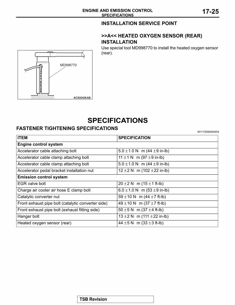
>>A<< HEATED OXYGEN SENSOR (REAR) INSTALLATION
ACX02426AB
MD998770
Use special tool MD998770 to install the heated oxygen sensor (rear).
SPECIFICATIONSFASTENER TIGHTENING SPECIFICATIONS
M1173006400454
ITEM SPECIFICATIONEngine control systemAccelerator cable attaching bolt 5.0 ± 1.0 N⋅ m (44 ± 9 in-lb)Accelerator cable clamp attaching bolt 11 ± 1 N⋅ m (97 ± 9 in-lb)Accelerator cable clamp attaching bolt 5.0 ± 1.0 N⋅ m (44 ± 9 in-lb)Accelerator pedal bracket installation nut 12 ± 2 N⋅ m (102 ± 22 in-lb)Emission control systemEGR valve bolt 20 ± 2 N⋅ m (15 ± 1 ft-lb)Charge air cooler air hose E clamp bolt 6.0 ± 1.0 N⋅ m (53 ± 9 in-lb)Catalytic converter nut 59 ± 10 N⋅ m (44 ± 7 ft-lb)Front exhaust pipe bolt (catalytic converter side) 49 ± 10 N⋅ m (37 ± 7 ft-lb)Front exhaust pipe bolt (exhaust fitting side) 50 ± 5 N⋅ m (37 ± 4 ft-lb)Hanger bolt 13 ± 2 N⋅ m (111 ± 22 in-lb)Heated oxygen sensor (rear) 44 ± 5 N⋅ m (33 ± 3 ft-lb)
TSB Revision
SPECIFICATIONSENGINE AND EMISSION CONTROL17-26
SERVICE SPECIFICATIONSM1173000300437
ITEMS STANDARD VALUEEngine control systemAccelerator cable free play mm (in) 1 − 2 (0.04 − 0.08)Curb idle speed r/min 850 ± 50Emission control system
Purge flow cm3/s (SCFH) [at 80 − 95° C (176 − 205° F) with sudden revving] 20 (2.5)
Evaporative emission purge solenoid coil resistance [at 20° C (68° F)] Ω 30 − 34EGR port vacuum [at idle] kPa (in Hg) 51 (15) or moreRequired time for EGR vacuum to reach 51 kPa (15 in Hg) second 1.0 or lessEGR vacuum regulator solenoid valve coil resistance [at 20° C (68° F)] Ω 29 − 35Evaporative emission ventilation solenoid coil resistance [at 20° C (68° F)] Ω 17 − 21
TSB Revision