Embed Size (px)
Citation preview

14-1
GROUP 14
ENGINE COOLINGCONTENTS
GENERAL DESCRIPTION. . . . . . . . . 14-2
SPECIAL TOOL . . . . . . . . . . . . . . . . . 14-2
ENGINE COOLING DIAGNOSIS . . . . 14-2INTRODUCTION. . . . . . . . . . . . . . . . . . . . . 14-2TROUBLESHOOTING STRATEGY . . . . . . 14-2SYMPTOM CHART. . . . . . . . . . . . . . . . . . . 14-3SYMPTOM PROCEDURES . . . . . . . . . . . . 14-3
ON-VEHICLE SERVICE. . . . . . . . . . . 14-26ENGINE COOLANT LEAK CHECK . . . . . . 14-26RADIATOR CAP PRESSURE CHECK. . . . 14-27ENGINE COOLANT REPLACEMENT . . . . 14-27ENGINE COOLANT CONCENTRATION TEST 14-29FAN CONTROLLER CHECK . . . . . . . . . . . 14-29FAN CONTROL RELAY CONTINUITY CHECK 14-31
RADIATOR . . . . . . . . . . . . . . . . . . . . . 14-32REMOVAL AND INSTALLATION . . . . . . . . 14-32
THERMOSTAT . . . . . . . . . . . . . . . . . . 14-35REMOVAL AND INSTALLATION . . . . . . . . 14-35INSPECTION. . . . . . . . . . . . . . . . . . . . . . . . 14-38
WATER PUMP . . . . . . . . . . . . . . . . . . 14-39REMOVAL AND INSTALLATION . . . . . . . . 14-39
WATER HOSE AND WATER PIPE . . 14-40REMOVAL AND INSTALLATION . . . . . . . . 14-40INSPECTION. . . . . . . . . . . . . . . . . . . . . . . . 14-41
SPECIFICATIONS . . . . . . . . . . . . . . . 14-42FASTENER TIGHTENING SPECIFICATIONS. . . . . . . . . . . . . . . . . . . . 14-42SERVICE SPECIFICATION . . . . . . . . . . . . 14-43CAPACITIES . . . . . . . . . . . . . . . . . . . . . . . . 14-43SEALANTS . . . . . . . . . . . . . . . . . . . . . . . . . 14-43

GENERAL DESCRIPTIONENGINE COOLING 14-2
GENERAL DESCRIPTIONM1141000100401
• The cooling system is designed to keep every part of the engine at appropriate temperature in whatever condition the engine may be operated. The cooling method is of the water-cooled, pres-sure forced circulation type in which the water pump pressurizes coolant and circulates it throughout the engine. If the coolant temperature
exceeds the prescribed temperature, the thermo-stat opens to circulate the coolant through the radiator as well so that the heat absorbed by the coolant may be radiated into the air. The water pump is of the centrifugal type and is driven by the drive belt from the crankshaft. The radiator is the corrugated fin, down flow type.
SPECIAL TOOLM1141000600279
ENGINE COOLING DIAGNOSISINTRODUCTION
M1141005300347The system cools the engine so that it does not over-heat and maintains the engine at an optimum tem-perature. The system components are the radiator, water pump, thermostat, condenser and fan assem-blies. Possible faults include low coolant, contamina-tion, belt loosening and component damage.
TROUBLESHOOTING STRATEGYM1141005200340
Use these steps to plan your diagnostic strategy. If you follow them carefully, you will be sure to find most of the engine cooling faults.1. Gather information from the customer.
2. Verify that the condition described by the customer exists.
3. Find and repair the malfunction by following the SYMPTOM CHART.
4. Verify that the malfunction is eliminated.
TOOL TOOL NUMBER AND NAME
SUPERSESSION APPLICATION
MB991871LLC changer
General service tool Coolant refilling
MB991871

ENGINE COOLING DIAGNOSISENGINE COOLING 14-3
SYMPTOM CHARTM1141005600393
SYMPTOM PROCEDURES
INSPECTION PROCEDURE 1: Coolant Leak
DIAGNOSIS
STEP 1. Check for coolant leaks.WARNING
When pressure testing the cooling system, slowly release cooling system pressure to avoid being burned by hot coolant.
CAUTION• Be sure to completely clean away any moisture from
the places checked.• When the tester is removed, be careful not to spill any
coolant.• When installing and removing the tester and when test-
ing, be careful not to deform the filler neck of the radia-tor.
Check that the coolant level is up to the filler neck. Install a radi-ator tester and apply 160 kPa (23 psi) pressure, and then check for leakage from the radiator hose or connections.Q: Is leakage present from the radiator hose or
connections?YES : Repair or replace the appropriate part, then go to
Step 2.NO : There is no action to be taken.
STEP 2. Retest the system.Q: Is there still coolant leakage?
YES : Return to Step 1.NO : The procedure is complete.
SYMPTOM INSPECTION PROCEDURE
REFERENCE PAGE
Coolant leak 1 14-3Engine overheating 2 14-4Radiator fan and condenser fan do not operate 3 14-4Radiator fan and condenser fan do not change speed or stop 4 14-20Radiator fan does not operate 5 14-25Condenser fan does not operate 6 14-25
ACX01844 AB
CAP ADAPTER
ADAPTER

ENGINE COOLING DIAGNOSISENGINE COOLING 14-4
INSPECTION PROCEDURE 2: Engine Overheating
DIAGNOSIS
STEP 1. Remove the radiator cap and check for coolant contamination.Q: Is the coolant contaminated with rust and oil?
YES : Replace it. Refer to P.14-27.NO : There is no action to be taken. Go to Step 2.
STEP 2. Check the radiator cap valve opening pressure.NOTE: Be sure that the cap is clean before testing. Rust or other foreign material on the cap seal will cause an improper reading.(1) Use a cap adapter to attach the cap to the tester.(2) Increase the pressure until the gauge indicator stops
moving.Minimum limit: 83 kPa (12 psi)Standard value: 93 − 123 kPa (14 − 18 psi)
Q: Does the reading remain at or above the minimum limit?YES : Go to Step 3.NO : Replace the radiator cap. Then go to Step 5.
STEP 3. Check thermostat operation.Refer to 38.Q: Does the thermostat operate correctly?
YES : Go to Step 4.NO : Replace the thermostat, then go to Step 5.
STEP 4. Check the drive belt for slippage or damage.Refer to GROUP 00, Maintenance Service − Drive Belts (Check Condition). <3.8L Engine>39 .Q: Is the drive belt loose or damaged?
YES : Adjust or replace the drive belt, then go to Step 5.NO : There is no action to be taken.
STEP 5. Retest the system.Check the engine coolant temperature.Q: Is the engine coolant temperature abnormally high?
YES : Return to Step 2.NO : The procedure is complete.
ACX01845 AB
CAP ADAPTER

ENGINE COOLING DIAGNOSISENGINE COOLING 14-5
INSPECTION PROCEDURE 3: Radiator Fan and Condenser Fan do not Operate
.
CIRCUIT OPERATION• The fan controller is powered from fusible link
No.2.• The engine-ECU uses input signals from the A/C
switch, the water temperature sensor unit and the vehicle speed sensor <M/T> or the output shaft speed sensor <A/T> to control the speed of the radiator fan motor and the condenser fan motor.
• The engine-ECU controls the fan controller to activate the radiator fan motor and the condenser fan motor.
.
TECHNICAL DESCRIPTION• The cause could be a malfunction of the fan con-
troller power supply or earth circuit.• If the communication line wiring harness between
the fan controller and the engine-ECU is short-circuited to earth, the radiator fan motor and the condenser fan motor will not rotate.
• The cause could also be a malfunction of input signal from the A/C switch, the water temperature sensor unit and the vehicle speed sensor <M/T> or the output shaft speed sensor <A/T> to the engine-ECU.
• The cause could also be a malfunction of the fan controller or the engine-ECU.
.
TROUBLESHOOTING HINTS• Malfunction of fusible link No.2• Malfunction of fan control relay• Malfunction of cooling fan motor and fan control-
ler• Malfunction of engine-ECU.• Damaged wiring harness or connector• Refer to component locations GROUP-1• Refer to configuration diagrams GROUP-1• Refer to circuit diagrams GROUP-1

ENGINE COOLING DIAGNOSISENGINE COOLING 14-6
DIAGNOSIS
STEP 1. Measure the power supply voltage at fan controller connector A-24.
(1) Disconnect fan controller connector A-24 and measure wiring harness side connector.
(2) Turn the ignition switch to the "ON" position.
(3) Measure the voltage between fan controller connector A-24 terminal 3 and body earth.• The voltage should measure system voltage.
(4) Turn the ignition switch to the "LOCK" (OFF) position.(5) Connect fan controller connector A-24.Q: Is the measured voltage system voltage?
YES : Go to Step 17.NO : Go to Step 2.
STEP 2. Check the fan controller connector A-24.
Q: Is the connector in good condition?YES : Go to Step 3.NO : Repair or replace the connector. Then go to Step 24.
04DB008A
123
A-24
Connector: A-24
3 2 1
04DB009A
Connector A-24(Component side)
04DB008A
123
A-24
Connector: A-24

ENGINE COOLING DIAGNOSISENGINE COOLING 14-7
STEP 3. Check the fusible link No.2.
Q: Is the fusible link No.2 in good condition?YES : Go to Step 4.NO : Replace the fusible link No.2. Then go to Step 24.
STEP 4. Measure the power supply voltage at fan control relay connector A-10X.
(1) Disconnect fan control relay connector A-10X (remove the fan control relay) and measure relay box side connector.
(2) Turn the ignition switch to the "ON" position.
(3) Measure the voltage between fan control relay connector A-10X terminal 4 and body earth.• The voltage should measure system voltage.
(4) Turn the ignition switch to the "LOCK" (OFF) position.(5) Connect fan control relay connector A-10X (install the fan
control relay).Q: Is the measured voltage system voltage?
YES : Go to Step 7.NO : Go to Step 5.
04DB010A
Fusible linkNo.2
Relay box
Fan controlrelay
04DB012A
Fusible linkNo.2
Relay box
Fan controlrelayA-10X
4
04DB013A
A-10X Connector(Relay box side)

ENGINE COOLING DIAGNOSISENGINE COOLING 14-8
STEP 5. Check the fan control relay connector A-10X.
Q: Is the connector in good condition?YES : Go to Step 6.NO : Repair the connector or replace the relay box. Then
go to Step 24.
STEP 6. Check the harness wire between fusible link No.2 and fan control relay connector A-10X terminal 4.
Q: Is the harness wire in good condition?YES : An intermittent malfunction is suspected (Refer to
GROUP 00 - How to use troubleshooting 00-7).NO : Repair the damaged harness wire. Then go to Step
24.
STEP 7. Check the fan control relay.Refer to 14-31.Q: Is the fan control relay in good condition?
YES : Go to Step 8.NO : Replace the fan control relay. Then go to Step 24.
04DB012A
Fusible linkNo.2
Relay box
Fan controlrelayA-10X
4
04DB010A
Fusible linkNo.2
Relay box
Fan controlrelay
04DB012A
Fusible linkNo.2
Relay box
Fan controlrelayA-10X
4

ENGINE COOLING DIAGNOSISENGINE COOLING 14-9
STEP 8. Check the fan control relay connector A-10X.
Q: Is the connector in good condition?YES : Go to Step 9.NO : Repair the connector or replace the relay box. Then
go to Step 24.
STEP 9. Check the harness wire between fan control relay connector A-10X terminal 2 and fan controller connector A-24 terminal 3.
Q: Is the harness wire in good condition?YES : Go to Step 10.NO : Repair the damaged harness wire. Then go to Step
24.
04DB012A
Fusible linkNo.2
Relay box
Fan controlrelayA-10X
4
04DB012A
Fusible linkNo.2
Relay box
Fan controlrelayA-10X
4
04DB008A
123
A-24
Connector: A-24

ENGINE COOLING DIAGNOSISENGINE COOLING 14-10
STEP 10. Measure the terminal voltage at fan control relay connector A-10X.
(1) Disconnect fan control relay connector A-10X (remove the fan control relay) and measure relay box side connector.
(2) Turn the ignition switch to the "ON" position.
(3) Measure the voltage between fan control relay connector A-10X terminal 3 and body earth.• The voltage should measure system voltage.
(4) Turn the ignition switch to the "LOCK" (OFF) position.(5) Connect fan control relay connector A-10X (install the fan
control relay).Q: Is the measured voltage system voltage?
YES : Go to Step 13.NO : Go to Step 11.
04DB012A
Fusible linkNo.2
Relay box
Fan controlrelayA-10X
4
04DB014A
A-10X Connector(Relay box side)

ENGINE COOLING DIAGNOSISENGINE COOLING 14-11
STEP 11. Check the ECU connector B-21, intermediate connector A-13 and fan control relay connector A-10X.
Q: Are there connectors in good condition?YES : Go to Step 12.NO : Repair or replace the connector. Then go to Step 24.
16DB400A
COVERENGINECONTROLUNIT
AIRCLEANER
AK303148
CONNECTOR: A-13
AB
A-13(GR)
04DB012A
Fusible linkNo.2
Relay box
Fan controlrelayA-10X
4

ENGINE COOLING DIAGNOSISENGINE COOLING 14-12
STEP 12. Check the harness wire between intermediate connector A-13 terminal 2 and fan control relay connector A-10X terminal 3.
Q: Are these harness wires in good condition?YES : An intermittent malfunction is suspected (Refer to
00-7).NO : Repair the damaged harness wire. Then go to Step
24.
AK303148
CONNECTOR: A-13
AB
A-13(GR)
04DB012A
Fusible linkNo.2
Relay box
Fan controlrelayA-10X
4

ENGINE COOLING DIAGNOSISENGINE COOLING 14-13
STEP 13. Check the continuity between fan control relay connector A-10X and body earth.
(1) Disconnect fan control relay connector A-10X (remove the fan control relay) and measure relay box side connector.
(2) Measure the resistance between fan control relay connector A-10X terminal 1 and body earth.• Continuity exists.
(3) Connect fan control relay connector A-10X (install the fan control relay).
Q: Does the continuity exists?YES : An intermittent malfunction is suspected (Refer to
00-7).NO : Go to Step 14.
STEP 14. Check the fan control relay connector A-10X.
Q: Is the connector in good condition?YES : Go to Step 15.NO : Repair the connector or replace the relay box. Then
go to Step 24.
04DB012A
Fusible linkNo.2
Relay box
Fan controlrelayA-10X
4
04DB015A
A-10X Connector(Relay box side)
04DB012A
Fusible linkNo.2
Relay box
Fan controlrelayA-10X
4

ENGINE COOLING DIAGNOSISENGINE COOLING 14-14
STEP 15. Check the earth connector A-14.
Q: Is the connector in good condition?YES : Go to Step 16.NO : Repair or replace the connector. Then go to Step 24.
STEP 16. Check the harness wire between fan control relay connector A-10X terminal 1 and body earth connector A-14 terminal 6.
Q: Is the harness wire in good condition?YES : An intermittent malfunction is suspected (Refer to
GROUP 00 - How to use troubleshooting 00-7).NO : Repair the damaged harness wire. Then go to Step
24.
04DB019A
RELAY BOX
A-14
04DB012A
Fusible linkNo.2
Relay box
Fan controlrelayA-10X
4
04DB019A
RELAY BOX
A-14

ENGINE COOLING DIAGNOSISENGINE COOLING 14-15
STEP 17. Check the continuity between fan controller connector A-24 and body earth.
(1) Disconnect fan controller connector A-24 and measure wiring harness side connector.
(2) Measure the resistance between fan controller connector A-24 terminal 1 and body earth.• Continuity exists.
(3) Connect fan controller connector A-24.Q: Dose the continuity exists?
YES : Go to Step 20.NO : Go to Step 18.
STEP 18. Check the fan controller connector A-24.
Q: Is the connector in good condition?YES : Go to Step 19.NO : Repair or replace the connector. Then go to Step 24.
04DB008A
123
A-24
Connector: A-24
04DB016A
A-24 Connector(Wiring harness side)
04DB008A
123
A-24
Connector: A-24

ENGINE COOLING DIAGNOSISENGINE COOLING 14-16
STEP 19. Check the harness wire between fan controller connector A-24 terminal 1 and body earth.
Q: Is the harness wire in good condition?YES : An intermittent malfunction is suspected (Refer to
GROUP 00 - How to use troubleshooting 00-7).NO : Repair the damaged harness wire. Then go to Step
24.
04DB008A
123
A-24
Connector: A-24

ENGINE COOLING DIAGNOSISENGINE COOLING 14-17
STEP 20. Check the fan controller connector A-24, intermediate connector A-13 and engine-ECU connector B-21.
Q: Are these connectors in good condition?YES : Go to Step 21.NO : Repair or replace the connector. Then go to Step 24.
04DB008A
123
A-24
Connector: A-24
AK303148
CONNECTOR: A-13
AB
A-13(GR)
16DB400A
COVERENGINECONTROLUNIT
AIRCLEANER
ENGINE COOLING DIAGNOSISENGINE COOLING 14-18
STEP 21. Check the harness wire between fan controller connector A-24 terminal 2 and engine-ECU connector B-21 terminal 71.
Q: Are these harness wires in good condition?YES : Go to Step 22.NO : Repair the damaged harness wire. Then go to Step
24.
04DB008A
123
A-24
Connector: A-24
16DB400A
COVERENGINECONTROLUNIT
AIRCLEANER

ENGINE COOLING DIAGNOSISENGINE COOLING 14-19
STEP 22. Check the fan controller.
(1) Disconnect fan controller connector A-24.
(2) Back out connector terminal pin 2 from connector housing.(3) Reconnect the connector with connector terminal pin 2 still
removed.(4) Turn the ignition switch to the "ON" position.(5) Check for the cooling fan operation.
• The cooling fan rotates. (with connector terminal pin 2 disconnected)
(6) Check for the cooling fan operation.• Using a suitable probe connect the fan controller termi-
nal 2 at controller side to earth.The cooling fan stops. (When pin 2 of fan controller is connected to earth)
(7) Turn the ignition switch to the "OFF" position.(8) Disconnect fan controller connector A-24, and re-locate
connector terminal pin 2 into connector housing.(9) Reconnect the connector with connector terminal pin 2
installed correctly.Q: Does the cooling fan rotate? And when the fan
controller pin 2 is connected to the body earth, does the cooling fan stop?YES : Go to Step 23.NO : Replace the fan motor and fan controller (Refer to
14-25). Then go to Step 24.
16DB400A
COVERENGINECONTROLUNIT
AIRCLEANER
04DB008A
123
A-24
Connector: A-24

ENGINE COOLING DIAGNOSISENGINE COOLING 14-20
STEP 23. MUT-III self-diag codeCheck if an MPI system self-diag code is set. (Refer to GROUP 13A - Trouble shooting 13A-5).Q: Diagnosis code set?
YES : Inspection chart for diagnosis code (Refer to GROUP 13A - Trouble shooting 13A-17)
NO : Replace the engine-ECU (Refer to GROUP 13A, Engine-ECU 13A-675 ). Then go to Step 24.
STEP 24. Check the symptoms.Q: Does the radiator fan motor and the condenser fan
motor operate correctly?YES : This symptom is complete.NO : Return to Step 1.
INSPECTION PROCEDURE 4: Radiator Fan and Condenser Fan do not Change Speed or Stop
.
Radiator Fan and Condenser Fan Drive CircuitRefer to 5..
TECHNICAL DESCRIPTION• The cause could be a malfunction of the fan con-
troller power supply or earth circuit.• If the communication line wiring harness between
the fan controller and the engine-ECU is short-circuited to earth, the radiator fan motor and the condenser fan motor will not rotate.
• The cause could also be a malfunction of input signal from the A/C switch, the water temperature sensor unit and the vehicle speed sensor <M/T> or the output shaft speed sensor <A/T> to the engine-ECU.
• The cause could also be a malfunction of the fan controller or the engine-ECU.
.
TROUBLESHOOTING HINTS• Malfunction of fusible link No.2• Malfunction of fan control relay• Malfunction of cooling fan motor• Malfunction of fan controller• Malfunction of engine-ECU• Damaged wiring harness or connector
DIAGNOSIS
STEP 1. Check the fan control relay.Refer to 14-31.Q: Is the fan control relay in good condition?
YES : Go to Step 2.NO : Replace the fan control relay. Then go to Step 8.

ENGINE COOLING DIAGNOSISENGINE COOLING 14-21
STEP 2. Check the fan control relay connector A-10X.
Q: Is the connector in good condition?YES : Go to Step 3.NO : Repair the connector or replace the relay box. Then
go to Step 8.
STEP 3. Check the harness wire between fan control relay connector A-10X terminal 2 and fan controller connector A-24 terminal 3.
Q: Is the harness wire in good condition?YES : Go to Step 4.NO : Repair the damaged harness wire. Then go to Step 8.
04DB012A
Fusible linkNo.2
Relay box
Fan controlrelayA-10X
4
04DB012A
Fusible linkNo.2
Relay box
Fan controlrelayA-10X
4
04DB008A
123
A-24
Connector: A-24

ENGINE COOLING DIAGNOSISENGINE COOLING 14-22
STEP 4. Check the fan controller connector A-24, intermediate connector A-13 and engine-ECU connector B-21.
Q: Are these connectors in good condition?YES : Go to Step 5.NO : Repair or replace the connector. Then go to Step 8.
04DB008A
123
A-24
Connector: A-24
AK303148
CONNECTOR: A-13
AB
A-13(GR)
16DB400A
COVERENGINECONTROLUNIT
AIRCLEANER

ENGINE COOLING DIAGNOSISENGINE COOLING 14-23
STEP 5. Check the harness wire between fan controller connector A-24 terminal 2 and engine-ECU connector B-21 terminal 71.
Q: Are these harness wires in good condition?YES : Go to Step 6.NO : Repair the damaged harness wire. Then go to Step 8.
04DB008A
123
A-24
Connector: A-24
16DB400A
COVERENGINECONTROLUNIT
AIRCLEANER
ENGINE COOLING DIAGNOSISENGINE COOLING 14-24
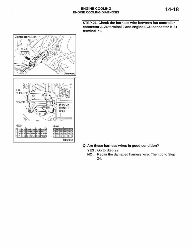
STEP 6. Check the fan controller.
(1) Disconnect fan controller connector A-24.
(2) Back out connector terminal pin 2 from connector housing.(3) Reconnect the connector with connector terminal pin 2 still
removed.(4) Turn the ignition switch to the "ON" position.(5) Check for the cooling fan operation.
• The cooling fan rotates. (with connector terminal pin 2 disconnected)
(6) Check for the cooling fan operation.• Using a suitable probe connect the fan controller termi-
nal 2 at controller side to earth.The cooling fan stops. (When pin 2 of fan controller is connected to earth)
(7) Turn the ignition switch to the "OFF" position.(8) Disconnect fan controller connector A-24, and re-locate
connector terminal pin 2 into connector housing.(9) Reconnect the connector with connector terminal pin 2
installed correctly.Q: Does the cooling fan rotate? And when the fan
controller pin 2 is connected to the body earth, does the cooling fan stop?YES : Go to Step 7.NO : Replace the fan motor and fan controller (Refer to
14-25). Then go to Step 8.
16DB400A
COVERENGINECONTROLUNIT
AIRCLEANER
04DB008A
123
A-24
Connector: A-24
ENGINE COOLING DIAGNOSISENGINE COOLING 14-25
STEP 7. MUT-III self-diag codeCheck if an MPI system self-diag code is set. (Refer to GROUP 13A - Trouble shooting 13A-5)Q: Diagnosis code set?
YES : Inspection chart for diagnosis code (Refer to GROUP 13A - Trouble shooting 13A-5)
NO : Replace the engine-ECU (Refer to GROUP 13A, Engine-ECU 13A-675 ) Then go to Step 8 .
STEP 8. Check the symptoms.Q: Does the radiator fan motor and the condenser fan
motor operate correctly?YES : This symptom is complete.NO : Return to Step 1.
INSPECTION PROCEDURE 5: Radiator Fan does not Operate
.
Radiator Fan and Condenser Fan Drive Circuit
.
TECHNICAL DESCRIPTIONThe cause could be a malfunction of the radiator fan motor or an open circuit between the fan controller and the radiator fan motor.
.
TROUBLESHOOTING HINTS• Malfunction of radiator fan motor• Malfunction of fan controller• Refer to component locations GROUP-1• Refer to configuration diagrams GROUP-1• Refer to circuit diagrams GROUP-1
DIAGNOSISReplace the radiator fan motor and fan controller assembly.Q: Does the radiator fan operate correctly?
YES : There is no action to be taken?NO : Repair the wiring harness between the fan controller
and the radiator fan motor.
INSPECTION PROCEDURE 6: Condenser Fan does not Operate
.
Radiator Fan and Condenser Fan Drive Circuit
.
TECHNICAL DESCRIPTIONThe cause could be a malfunction of the condenser fan motor or fan controller.
.
TROUBLESHOOTING HINTS• Malfunction of condenser fan motor• Malfunction of fan controller• Refer to component locations GROUP-1• Refer to configuration diagrams GROUP-1• Refer to circuit diagrams GROUP-1

ON-VEHICLE SERVICEENGINE COOLING 14-26
DIAGNOSIS
STEP 1. Check the condenser fan motor.Condenser fan motor check. (Refer to GROUP 55, Condenser and Condenser Fan Motor.Q: Is the condenser fan motor in good condition?
YES : Go to Step 2.NO : Replace the condenser fan motor, then go to Step 3.
STEP 2. Check the fan controller.Refer to 29.Q: Is the fan controller in good condition?
YES : Go to Step 3.NO : Replace the fan motor and fan controller (Refer to
14-25). Then go to Step 3.
STEP 3. Check the symptoms.Q: Do the condenser fan operate?
YES : This symptom is complete.NO : Return to Step 1.
ON-VEHICLE SERVICEENGINE COOLANT LEAK CHECK
M1141001000333
WARNINGWhen pressure testing the cooling system, slowly release cooling system pressure to avoid getting burned by hot coolant.
CAUTION• Be sure to completely clean away any moisture from
the places checked.• When the tester is taken out, be careful not to spill any
coolant.• Be careful when installing and removing the tester and
when testing not to deform the filler neck of the radia-tor.
1. Check that the coolant level is up to the filler neck. Install a radiator tester and apply 160 kPa (23 psi) pressure, and then check for leakage from the radiator hose or connections.
2. If there is leakage, repair or replace the appropriate part.
ACX01844 AB
CAP ADAPTER
ADAPTER

ON-VEHICLE SERVICEENGINE COOLING 14-27
RADIATOR CAP PRESSURE CHECKM1141001300419
NOTE: Be sure that the cap is clean before testing. Rust or other foreign material on the cap seal will cause an improper reading.
1. Use a cap adapter to attach the cap to the tester.2. Increase the pressure until the indicator of the gauge stops
moving.Minimum limit: 83 kPa (12 psi)Standard value: 93 − 123 kPa (14 − 18 psi)
3. Replace the radiator cap if the reading does not remain at or above the limit.
ENGINE COOLANT REPLACEMENTM1141001200478
WARNINGWhen removing the radiator cap, use care to avoid contact with hot coolant or steam. Place a shop towel over the cap and turn the cap counterclockwise a lit-tle to let the pressure escape through the vinyl tube. After relieving the steam pressure, remove the cap by slowly turning it counterclockwise.1. Drain the water from the radiator, heater core and engine
after unplugging the radiator drain plug and removing the radiator cap.
ACX01845 AB
CAP ADAPTER

ON-VEHICLE SERVICEENGINE COOLING 14-28
2. Drain the water in the water jacket by unplugging the drainplug of the cylinder block.3. Remove the radiator condenser tank assembly and drain the
coolant.4. Drain the coolant then clean the path of the coolant by
injecting water into the radiator from the radiator cap area.
5. Apply the designated sealant to the screw area of the cylinder block drain plug, and then tighten to the standard torque.
Specified sealant: 3M™ AAD Part No.8731 or equiva-lent
Tightening torque:39 ± 5 N⋅m
6. Securely tighten the radiator drain plug.7. Assemble the radiator condenser tank assembly.
AC306131AB
<3.8L ENGINE: LEFT BANK>
CYLINDER BLOCK�DRAIN PLUG
AC306132AB
<3.8L ENGINE: RIGHT BANK>
CYLINDER BLOCK�DRAIN PLUG
AC200625AD
CYLINDER BLOCKDRAIN PLUG
<3.8L ENGINE: LEFT BANK>

ON-VEHICLE SERVICEENGINE COOLING 14-29
CAUTION• Do not use alcohol or methanol anti-freeze or any
engine coolants mixed with alcohol or methanol anti-freeze. The use of an improper anti-freeze can cause corrosion of the aluminum components.
8. By referring to the section on coolant, select an appropriate concentration for safe operating temperature within the range of 30 to 60 %. Use special tool MB991871 to refill the coolant. A convenient mixture is a 50 % water and 50 % antifreeze solution [freezing point: −31°C (−32.8 °F)].
Recommended antifreeze: Long Life Antifreeze Coolant or an equivalent
Quantity: 8.7 Litres
NOTE: For how to use special tool MB991871, refer to its manufacturer’s instructions.
9. Reinstall the radiator cap.10.Start the engine and let it warm up until the thermostat
opens.11.After repeatedly revving the engine up to 3,000 r/min several
times, stop the engine.12.Remove the radiator cap after the engine has cooled, and
pour in coolant up to the brim. Reinstall the cap.CAUTION
Do not overfill the radiator condenser tank assembly.13.Add coolant to the radiator condenser tank assembly
between the "FULL" and "LOW" mark if necessary.
ENGINE COOLANT CONCENTRATION TESTM1141001100396
Refer to GROUP 00, RECOMMENDED LUBRICANTS AND LUBRICANT CAPACITIES TABLE 35.
FAN CONTROLLER CHECKM1141007400113
1. Remove the fan controller connector.2. Turn the ignition switch to the "ON" position, and measure
the voltage between the harness-side connector terminals.Standard value: System voltage
AC306129
AIR HOSE MB991871
AB
04DB017A
23 1
Fan controller
ON-VEHICLE SERVICEENGINE COOLING 14-30
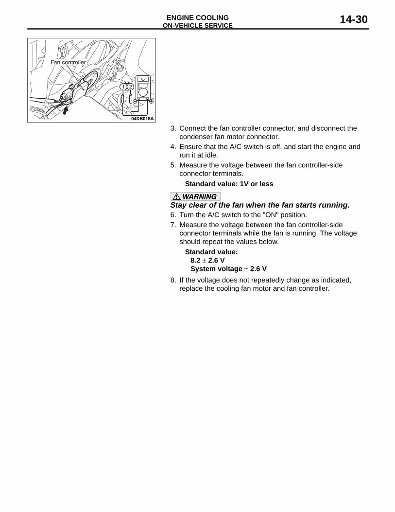
3. Connect the fan controller connector, and disconnect the condenser fan motor connector.
4. Ensure that the A/C switch is off, and start the engine and run it at idle.
5. Measure the voltage between the fan controller-side connector terminals.
Standard value: 1V or less
WARNINGStay clear of the fan when the fan starts running.6. Turn the A/C switch to the "ON" position.7. Measure the voltage between the fan controller-side
connector terminals while the fan is running. The voltage should repeat the values below.
Standard value:8.2 ± 2.6 VSystem voltage ± 2.6 V
8. If the voltage does not repeatedly change as indicated, replace the cooling fan motor and fan controller.
04DB018A
21
Fan controller

ON-VEHICLE SERVICEENGINE COOLING 14-31
FAN CONTROL RELAY CONTINUITY CHECKM1141006200310
BATTERY VOLTAGE
TERMINAL NO. TO BE CONNECTED TO TESTER
CONTINUITY TEST RESULTS
Not applied 4 − 2 Open circuit
Connect terminal No.3 and battery (−) terminal.Connect terminal No.1 and battery (+) terminal.
4 − 2 Less than 2 ohms
AC305017
1 34
2
3
4
1
2
AC307445
FAN CONTROL RELAY
AB

RADIATORENGINE COOLING 14-32
RADIATORREMOVAL AND INSTALLATION
M1141001500521
Pre-removal Operation• Engine Coolant Draining (Refer to 27).• Air Cleaner Removal (Refer to GROUP 15, Air Cleaner 4).
Post-installation Operation• Air Cleaner Installation (Refer to GROUP 15 4).• Engine Coolant Refilling and Level Check (Refer to 27).• A/T Fluid Refilling and Level Check (Refer to GROUP 00,
Maintenance Service 45).
04DB007A
22 ± 4 N·m16 ± 3 ft-lb
11 ± 2 N·m98 ± 17 in-lb
9
8
8
7
1
12
2
3
11
119
9
17
15
20
16 14
10
413
6
18
19
521
RADIATOR REMOVAL STEPS1. RADIATOR CONDENSER TANK
HOSE<<A>> >>A<< 2. RADIATOR UPPER HOSE<<A>> >>A<< 3. RADIATOR LOWER HOSE<<B>> 4. A/T OIL COOLER HOSE
CONNECTION5. CONDENSER FAN MOTOR
CONNECTOR6. FAN CONTROLLER CONNECTOR• HOOD LATCH (REFER TO
GROUP 42, HOOD 8).7. FRONT END STRUCTURE BAR8. UPPER INSULATOR9. CONDENSER BOLTS10. RADIATOR ASSEMBLY11. LOWER INSULATOR
12. RADIATOR CONDENSER TANK ASSEMBLY
<<B>> 13. A/T OIL COOLER HOSE14. CONDENSER FAN SHROUD
ASSEMBLY15. COOLING FAN SHROUD
ASSEMBLY16. RADIATOR
FAN MOTOR REMOVAL STEPS1. RADIATOR CONDENSER TANK
HOSE5. CONDENSER FAN MOTOR
CONNECTOR<<A>> >>A<< 3. RADIATOR UPPER HOSE
6. FAN MOTOR CONNECTOR12. RADIATOR CONDENSER TANK
ASSEMBLY
RADIATOR REMOVAL STEPS

RADIATORENGINE COOLING 14-33
14. CONDENSER FAN SHROUD ASSEMBLY
15. COOLING FAN SHROUD ASSEMBLY
17. CONDENSER FAN18. HEAT PROTECTOR19. CONDENSER FAN MOTOR20. COOLING FAN21. COOLING FAN MOTOR& FAN
CONTROLLER
FAN MOTOR REMOVAL STEPS RADIATOR CONDENSER TANK REMOVAL STEPS
• UNDER COVER (LH)• AIR INTAKE DUCT (REFER TO
GROUP 15, AIR CLEANER 4).1. RADIATOR CONDENSER TANK
HOSE5. CONDENSER FAN MOTOR
CONNECTOR6. FAN MOTOR CONNECTOR12. RADIATOR CONDENSER TANK
ASSEMBLY

RADIATORENGINE COOLING 14-34
REMOVAL SERVICE POINTS.
<<A>> RADIATOR UPPER HOSE/RADIATOR LOWER HOSE DISCONNECTIONMake mating marks on the radiator hose and the hose clamp. Disconnect the radiator hose.
.
<<B>> A/T OIL COOLER HOSE REMOVALAfter removing the hose from the radiator, plug the hose and the radiator nipple to prevent dust or foreign particles from get-ting in.
INSTALLATION SERVICE POINT.
>>A<< RADIATOR LOWER HOSE/RADIATOR UPPER HOSE CONNECTION1. Insert each hose as far as the projection of the water inlet
fitting.2. Align the mating marks on the radiator hose and hose
clamp, and then connect the radiator hose.
AC200641AB
MATING MARKS
AC200642
MATING�MARKS
PROJECTION
WATER OUTLET�FITTING
AB

THERMOSTATENGINE COOLING 14-35
THERMOSTATREMOVAL AND INSTALLATION
M1141002400475
Pre-removal and Post-installation Operation• Engine Coolant Draining and Refilling (Refer to 27).• Engine Cover Removal and Installation (Refer to GROUP
11C, Engine Assembly 11A-14).• Engine Control Unit (ECU) Removal and Installation
(Refer to GROUP 00, General 00-7).• Air Cleaner Removal and Installation (Refer to GROUP
15, Air Cleaner 4).• Strut Tower Bar Removal and Installation (Refer to
GROUP 42, Strut Tower Bar 12).• Battery and Battery Tray Removal and Installation
04DB006A
5.0 ± 1.0 N·m44 ± 9 in-lb
8
73
4
9
13
14
20
16
6
519
18
172
1
9.0 ± 2.0 N·m80 ± 17 in-lb
15
5.0 ± 1.0 N·m44 ± 9 in-lb
22 ± 4 N·m16 ± 3 ft-lb
13
10 11
REMOVAL STEPS1. LEFT BANK HEATED OXYGEN
SENSOR (REAR) CONNECTOR2. LEFT BANK HEATED OXYGEN
SENSOR (FRONT) CONNECTOR3. RIGHT BANK HEATED OXYGEN
SENSOR (REAR) CONNECTOR4. RIGHT BANK HEATED OXYGEN
SENSOR (FRONT) CONNECTOR5. THROTTLE BODY ASSEMBLY
CONNECTOR6. EVAPORATIVE EMISSION
PURGE SOLENOID CONNECTOR
7. MANIFOLD ABSOLUTE PRESSURE SENSOR CONNECTOR
8. POWER STEERING PRESSURE SWITCH CONNECTOR
9. CONTROL WIRING HARNESS AND WIRING HARNESS COMBINATION CONNECTOR
10. KNOCK SENSOR CONNECTOR11. CRANKSHAFT POSITION
SENSOR CONNECTOR13. INJECTOR CONNECTOR
REMOVAL STEPS (Continued)

THERMOSTATENGINE COOLING 14-36
14. ENGINE COOLANT TEMPERATURE SENSOR CONNECTOR
15. CAPACITOR CONNECTOR16. CAMSHAFT POSITION SENSOR
CONNECTOR17. INHIBITOR SWITCH SENSOR
CONNECTOR18. A/T CONTROL SOLENOID VALVE
ASSEMBLY CONNECTOR19. OUTPUT SHAFT SPEED
SENSOR CONNECTOR20. INPUT SHAFT SPEED SENSOR
CONNECTOR
REMOVAL STEPS (Continued)
AC306959AB
19 ± 1 N·m14 ± 1 ft-lb
21
2223
REMOVAL STEPS<<A>> >>B<< 21. RADIATOR LOWER HOSE
CONNECTION22. WATER INLET FITTING
>>A<< 23. THERMOSTAT
REMOVAL STEPS (Continued)

THERMOSTATENGINE COOLING 14-37
REMOVAL SERVICE POINT.
<<A>> RADIATOR LOWER HOSE DISCONNEC-TIONMake mating marks on the radiator hose and the hose clamp. Disconnect the radiator hose.
INSTALLATION SERVICE POINTS.
>>A<< THERMOSTAT INSTALLATIONCAUTION
Make absolutely sure that no oil adheres to the rubber ring of the thermostat. Also do not fold or scratch the rubber ring during installation.Install the thermostat so that the jiggle valve is facing straight up. Be careful not to fold or scratch the rubber ring.
.
>>B<< RADIATOR LOWER HOSE CONNECTION1. Insert each hose as far as the projection of the water inlet
fitting.2. Align the mating marks on the radiator hose and hose
clamp, and then connect the radiator hose.
AC200641AB
MATING MARKS
AC000279
JIGGLE VALVE
RUBBER RING
AB
AC200642
MATINGMARKS
PROJECTION
WATER INLET FITTING
AE

THERMOSTATENGINE COOLING 14-38
INSPECTIONM1141002500450
.
Thermostat Check1. Immerse the thermostat in water, and heat the water while
stirring. Check the thermostat valve opening temperature.Standard value:
Valve opening temperature:88 ± 1.5°C (190 ± 3°F)
2. Check that the amount of valve lift is at the standard value when the water is at the full-opening temperature.NOTE: Measure the valve height when the thermostat is fully closed, and use this measurement to compare the valve height when the thermostat is fully open.
Standard value:Full-opening temperature:
100°C (212°F)Amount of valve lift:
9.0 mm (0.35 inch) or more
ACX00400
ACX00401AB
VALVE LIFT

WATER PUMPENGINE COOLING 14-39
WATER PUMPREMOVAL AND INSTALLATION
M1141002700498
INSTALLATION SERVICE POINT.
>>A<< O-RING INSTALLATIONCAUTION
Do not let the O-ring get contaminated with grease or engine oil.Fit the O-ring into the groove of the water pipe ends, and apply water or coolant to the circumference of the O-ring and the pipe bores to insert the pipe assembly.
Pre-removal and Post-installation Operation• Engine Coolant Draining and Refilling (Refer to 27).• Timing Belt Removal and Installation (Refer to GROUP
11C, Timing Belt 11A-46).• Crankshaft Position Sensor Removal and Installation
(Refer to GROUP 16, Crankshaft Position Sensor 35).
AC205662
24 ± 3 N·m18 ± 2 ft-lb
42 ± 8 N·m31 ± 6 ft-lb
24 ± 3 N·m18 ± 2 ft-lb
1
2
3 4NN
AB
BOLT SPECIFICATIONS
THREAD DIAMETER × LENGTH mm(in)
10 × 38(0.4 × 1.5)
8 × 25(0.3 × 1.0)
8 × 25(0.3 × 1.0)
8 × 20(0.3 × 0.8)
REMOVAL STEPS 1. WATER PUMP BRACKET2. WATER PUMP
3. WATER PUMP GASKET>>A<< 4. O-RING
REMOVAL STEPS (Continued)
AC200644 AB
O-RING
WATER PIPE
WATER HOSE AND WATER PIPEENGINE COOLING 14-40
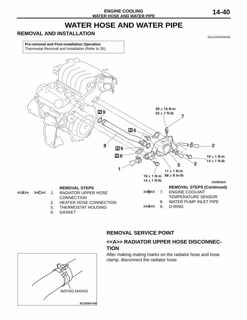
WATER HOSE AND WATER PIPEREMOVAL AND INSTALLATION
M1141003300493
REMOVAL SERVICE POINT.
<<A>> RADIATOR UPPER HOSE DISCONNEC-TIONAfter making mating marks on the radiator hose and hose clamp, disconnect the radiator hose.
Pre-removal and Post-installation OperationThermostat Removal and Installation (Refer to 35).
04DB020A
N
1
97
5
6
28
19 ± 1 N·m14 ± 1 ft-lb
19 ± 1 N·m14 ± 1 ft-lb
N
9N
N 6
11 ± 1 N·m98 ± 8 in-lb
2
29 ± 10 N·m22 ± 7 ft-lb
REMOVAL STEPS<<A>> >>C<< 1. RADIATOR UPPER HOSE
CONNECTION2. HEATER HOSE CONNECTION5. THERMOSTAT HOUSING6. GASKET
>>B<< 7. ENGINE COOLANT TEMPERATURE SENSOR
8. WATER PUMP INLET PIPE>>A<< 9. O-RING
REMOVAL STEPS (Continued)
AC200641AB
MATING MARKS

WATER HOSE AND WATER PIPEENGINE COOLING 14-41
INSTALLATION SERVICE POINTS.
>>A<< O-RING INSTALLATIONCAUTION
Do not allow engine oil or other grease to adhere to the O-ringInsert the O-ring to the water pipe, and coat the outer portion of the O-ring with water or engine coolant.
.
>>B<< ENGINE COOLANT TEMPERATURE SENSOR INSTALLATIONApply the specified sealant to the thread of the engine coolant temperature sensor, and then tighten it to the specified torque.
Specified Sealant: 3M™ AAD Part No. 8731 or equiva-lent
.
>>C<< RADIATOR UPPER HOSE CONNECTION1. Insert each hose as far as the projection of the water outlet
fitting.2. Align the mating marks on the radiator hose and hose
clamp, and then connect the radiator hose.
INSPECTIONM1141003400337
.
Water Pipe and Hose CheckCheck the water pipe and hose for cracks, damage and clogs. Replace them if necessary.
AC200644 AB
O-RING
WATER PIPE
AC208408AB
AC200642
MATING�MARKS
PROJECTION
WATER OUTLET�FITTING
AB

SPECIFICATIONSENGINE COOLING 14-42
SPECIFICATIONSFASTENER TIGHTENING SPECIFICATIONS
M1141005000346
ITEM SPECIFICATIONCylinder block drain plug 39 ± 5 N⋅m (29 ± 3 ft-lb)
RadiatorFront end structure bar bolt M8 × 10 11 ± 2 N⋅m (98 ± 17 in-lb)
M8 × 20 22 ± 4 N⋅m (16 ± 3 ft-lb)
Thermostat Control harness bolt 5.0 ± 1.0 N⋅m (44 ± 9 in-lb)Grounding bolt M6 9.0 ± 2.0 N⋅m (80 ± 17 in-lb)
M8 22 ± 4 N⋅m (16 ± 3 ft-lb)Water inlet fitting bolt 19 ± 1 N⋅m (14 ± 1 ft-lb)
Water hose and water pipe Engine coolant temperature sensor 29 ± 10 N⋅m Thermostat housing bolt 19 ± 1 N⋅m (14 ± 1 ft-lb)Water pump inlet pipe 11 ± 1 N⋅m (98 ± 8 ft-lb)
Water pump Water pump bolt M8 42 ± 8 N⋅m (31 ± 6 ft-lb)
M10 24 ± 3 N⋅m (18 ± 2 ft-lb)Water pump bracket bolt 24 ± 3 N⋅m (18 ± 2 ft-lb)

SPECIFICATIONSENGINE COOLING 14-43
SERVICE SPECIFICATIONM1141000300449
CAPACITIESM1141005100138
SEALANTSM1141000500368
ITEM STANDARD VALUE LIMITFan Controller V A/C OFF 1 or less -
A/C ON Repeat8.2 ± 2.6System voltage ± 2.6
-
High-pressure valve opening pressure of radiator cap kPa (psi) 93 − 123 (14 − 18) Minimum 83 (12)Thermostat Valve opening temperature
of thermostat °C (°F)3.8L Engine 88 ± 1.5 (190 ± 3)
-Full-opening temperature of thermostat °C (°F)
3.8L Engine 100 (212)-
Valve lift mm (in) 3.8L Engine 9.0 (0.35) or more-
ITEM QUANTITY dm3 (qt)Long life antifreeze coolant or an equivalent 3.8L Engine 8.7 (9.2)
ITEM SPECIFIED SEALANTCylinder block drain plug 3M™ AAD Part No.8731 or equivalentEngine coolant temperature sensor

SPECIFICATIONSENGINE COOLING 14-44