Embed Size (px)
Citation preview
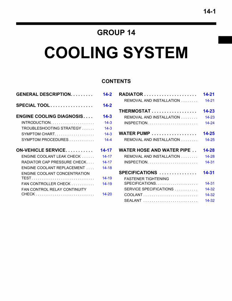
14-1
GROUP 14
CONTENTS
GENERAL DESCRIPTION. . . . . . . . . 14-2
SPECIAL TOOL . . . . . . . . . . . . . . . . . 14-2
ENGINE COOLING DIAGNOSIS . . . . 14-3INTRODUCTION. . . . . . . . . . . . . . . . . . . . . 14-3TROUBLESHOOTING STRATEGY . . . . . . 14-3SYMPTOM CHART. . . . . . . . . . . . . . . . . . . 14-3SYMPTOM PROCEDURES . . . . . . . . . . . . 14-4
ON-VEHICLE SERVICE. . . . . . . . . . . 14-17ENGINE COOLANT LEAK CHECK . . . . . . 14-17RADIATOR CAP PRESSURE CHECK. . . . 14-17ENGINE COOLANT REPLACEMENT . . . . 14-18ENGINE COOLANT CONCENTRATION TEST. . . . . . . . . . . . . . . . . . . . . . . . . . . . . . 14-19FAN CONTROLLER CHECK . . . . . . . . . . . 14-19FAN CONTROL RELAY CONTINUITY CHECK . . . . . . . . . . . . . . . . . . . . . . . . . . . . 14-20
RADIATOR . . . . . . . . . . . . . . . . . . . . . 14-21REMOVAL AND INSTALLATION . . . . . . . . 14-21
THERMOSTAT . . . . . . . . . . . . . . . . . . 14-23REMOVAL AND INSTALLATION . . . . . . . . 14-23INSPECTION. . . . . . . . . . . . . . . . . . . . . . . . 14-24
WATER PUMP . . . . . . . . . . . . . . . . . . 14-25REMOVAL AND INSTALLATION . . . . . . . . 14-25
WATER HOSE AND WATER PIPE . . 14-28REMOVAL AND INSTALLATION . . . . . . . . 14-28INSPECTION. . . . . . . . . . . . . . . . . . . . . . . . 14-31
SPECIFICATIONS . . . . . . . . . . . . . . . 14-31FASTENER TIGHTENING SPECIFICATIONS. . . . . . . . . . . . . . . . . . . . 14-31SERVICE SPECIFICATIONS . . . . . . . . . . . 14-32COOLANT . . . . . . . . . . . . . . . . . . . . . . . . . . 14-32SEALANT . . . . . . . . . . . . . . . . . . . . . . . . . . 14-32
GENERAL DESCRIPTIONCOOLING SYSTEM14-2
. GENERAL DESCRIPTIONM1141000100207
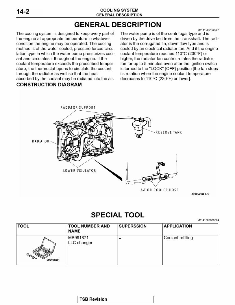
The cooling system is designed to keep every part of the engine at appropriate temperature in whatever condition the engine may be operated. The cooling method is of the water-cooled, pressure forced circu-lation type in which the water pump pressurizes cool-ant and circulates it throughout the engine. If the coolant temperature exceeds the prescribed temper-ature, the thermostat opens to circulate the coolant through the radiator as well so that the heat absorbed by the coolant may be radiated into the air.
The water pump is of the centrifugal type and is driven by the drive belt from the crankshaft. The radi-ator is the corrugated fin, down flow type and is cooled by an electrical radiator fan. And if the engine coolant temperature reaches 110°C (230°F) or higher, the radiator fan control rotates the radiator fan for up to 5 minutes even after the ignition switch is turned to the "LOCK" (OFF) position [the fan stops its rotation when the engine coolant temperature decreases to 110°C (230°F) or lower].
CONSTRUCTION DIAGRAM
SPECIAL TOOLM1141000600064
AC004034 ABA/T OIL COOLER HOSE
RESERVE TANK
LOWER INSULATOR
RADIATOR
RADIATOR SUPPORT
TOOL TOOL NUMBER AND NAME
SUPERSSION APPLICATION
MB991871LLC changer
− Coolant refilling
MB991871
TSB Revision
ENGINE COOLING DIAGNOSISCOOLING SYSTEM 14-3
ENGINE COOLING DIAGNOSISINTRODUCTION
M1141005300217The system cools the engine so that it does not over-heat and maintains the engine at an optimum tem-perature. The system components are the radiator, water pump, thermostat, condenser fan assembly. Possible faults include low coolant, contamination, belt loosening and component damage.
TROUBLESHOOTING STRATEGYM1141005200210
Use these steps to plan your diagnostic strategy. If you follow them carefully, you will be sure to find most of the engine cooling faults.1. Gather information from the customer.
2. Verify that the condition described by the customer exists.
3. Find and repair the malfunction by following the SYMPTOM CHART.
4. Verify that the malfunction is eliminated.
SYMPTOM CHARTM1141005600207
SYMPTOMS INSPECTION PROCEDURE
REFERENCE PAGE
Coolant Leak 1 P.14-4Engine Overheating 2 P.14-4Radiator Fan and Condenser Fan do not Operate 3 P.14-6Radiator Fan and Condenser Fan do not Change Speed or Stop 4 P.14-13Radiator Fan does not Operate 5 P.14-16Condenser Fan does not Operate 6 P.14-16
TSB Revision
ENGINE COOLING DIAGNOSISCOOLING SYSTEM14-4
SYMPTOM PROCEDURES
INSPECTION PROCEDURE 1: Coolant Leak.
DIAGNOSIS
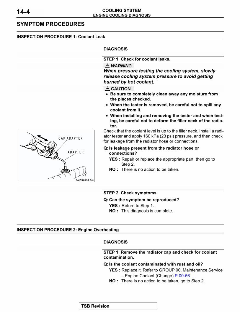
STEP 1. Check for coolant leaks.WARNING
When pressure testing the cooling system, slowly release cooling system pressure to avoid getting burned by hot coolant.
CAUTION• Be sure to completely clean away any moisture from
the places checked.• When the tester is removed, be careful not to spill any
coolant from it.• When installing and removing the tester and when test-
ing, be careful not to deform the filler neck of the radia-tor.
Check that the coolant level is up to the filler neck. Install a radi-ator tester and apply 160 kPa (23 psi) pressure, and then check for leakage from the radiator hose or connections.Q: Is leakage present from the radiator hose or
connections?YES : Repair or replace the appropriate part, then go to
Step 2.NO : There is no action to be taken.
STEP 2. Check symptoms.Q: Can the symptom be reproduced?
YES : Return to Step 1.NO : This diagnosis is complete.
INSPECTION PROCEDURE 2: Engine Overheating.
DIAGNOSIS
STEP 1. Remove the radiator cap and check for coolant contamination.Q: Is the coolant contaminated with rust and oil?
YES : Replace it. Refer to GROUP 00, Maintenance Service − Engine Coolant (Change) P.00-56.
NO : There is no action to be taken, go to Step 2.
ACX01844 AB
CAP ADAPTER
ADAPTER
TSB Revision
ENGINE COOLING DIAGNOSISCOOLING SYSTEM 14-5
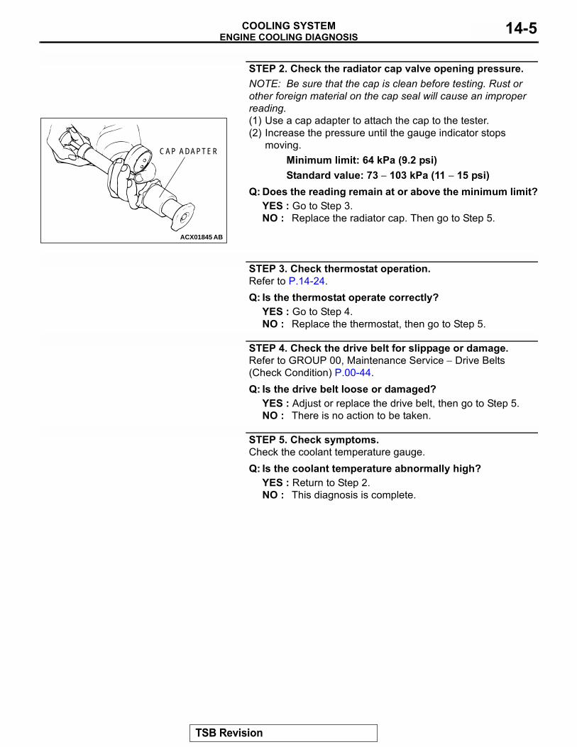
STEP 2. Check the radiator cap valve opening pressure.NOTE: Be sure that the cap is clean before testing. Rust or other foreign material on the cap seal will cause an improper reading.(1) Use a cap adapter to attach the cap to the tester.(2) Increase the pressure until the gauge indicator stops
moving.Minimum limit: 64 kPa (9.2 psi)Standard value: 73 − 103 kPa (11 − 15 psi)
Q: Does the reading remain at or above the minimum limit?YES : Go to Step 3.NO : Replace the radiator cap. Then go to Step 5.
STEP 3. Check thermostat operation.Refer to P.14-24.Q: Is the thermostat operate correctly?
YES : Go to Step 4.NO : Replace the thermostat, then go to Step 5.
STEP 4. Check the drive belt for slippage or damage.Refer to GROUP 00, Maintenance Service − Drive Belts (Check Condition) P.00-44.Q: Is the drive belt loose or damaged?
YES : Adjust or replace the drive belt, then go to Step 5.NO : There is no action to be taken.
STEP 5. Check symptoms.Check the coolant temperature gauge.Q: Is the coolant temperature abnormally high?
YES : Return to Step 2.NO : This diagnosis is complete.
ACX01845 AB
CAP ADAPTER
TSB Revision
ENGINE COOLING DIAGNOSISCOOLING SYSTEM14-6
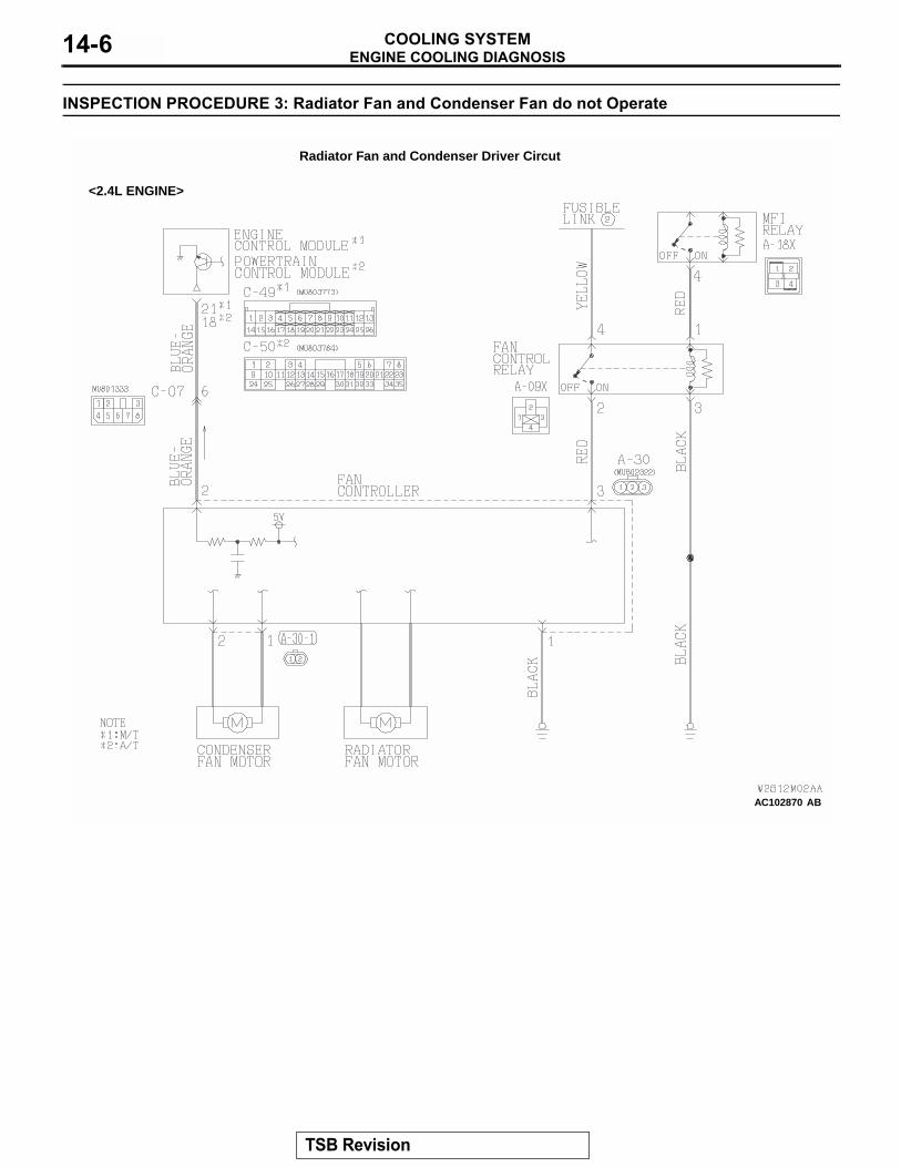
INSPECTION PROCEDURE 3: Radiator Fan and Condenser Fan do not Operate
AC102870
Radiator Fan and Condenser Driver Circut
<2.4L ENGINE>
AB
TSB Revision
ENGINE COOLING DIAGNOSISCOOLING SYSTEM 14-7
AC102871 AB
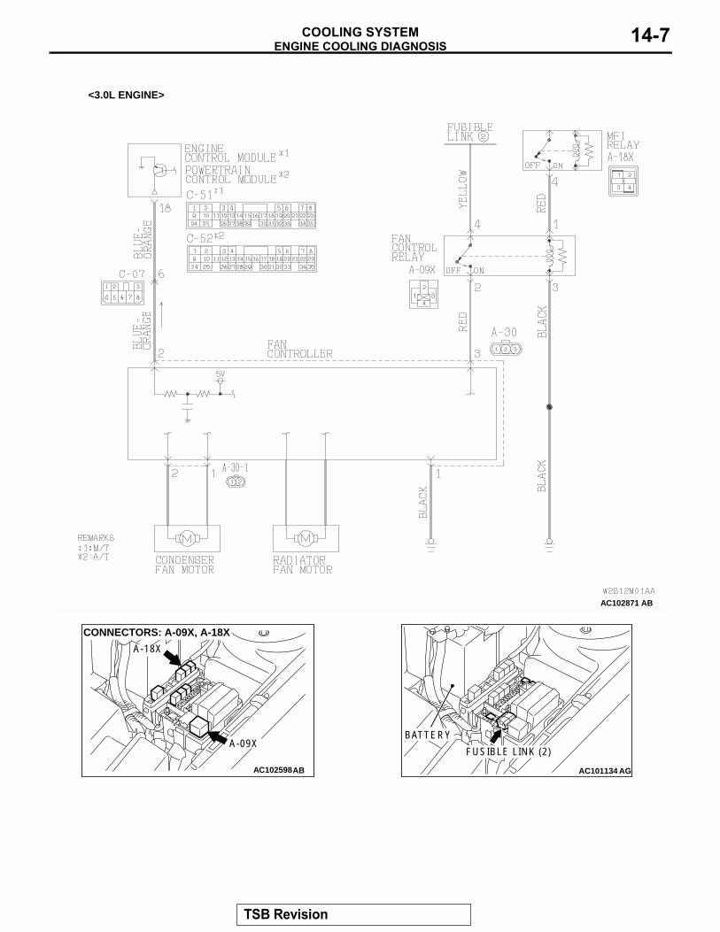
<3.0L ENGINE>
AC102598
CONNECTORS: A-09X, A-18X
A-18X
A-09X
AB AC101134
BATTERY
FUSIBLE LINK (2)
AG
TSB Revision
ENGINE COOLING DIAGNOSISCOOLING SYSTEM14-8
.
CIRCUIT OPERATION• The fan controller is powered from fusible link
number 2.• The ECM <M/T> or PCM <A/T> judges the
required revolution speed of radiator fan motor and condenser fan motor using the input signals transmitted from A/C switch, automatic compres-sor controller, vehicle speed sensor and engine coolant temperature sensor. The ECM <M/T> or PCM <A/T> activates the fan controller to drive the radiator fan motor and condenser fan motor.
.
TECHNICAL DESCRIPTION• The cause could be a malfunction of the fan con-
troller power supply or ground circuit.• The cause could also be a malfunction of the fan
controller or the ECM <M/T> or PCM <A/T>..
TROUBLESHOOTING HINTS• Malfunction of fusible link• Malfunction of fan control relay• Malfunction of fan controller• Malfunction of ECM <M/T> or PCM <A/T>• Damaged wiring harness or connector
.
DIAGNOSISRequired Special Tool:
• MB991223: Harness Set
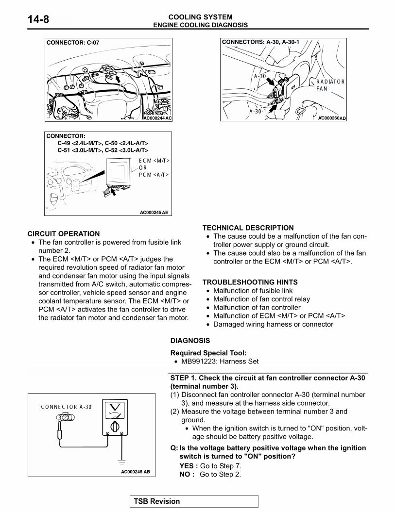
STEP 1. Check the circuit at fan controller connector A-30 (terminal number 3).(1) Disconnect fan controller connector A-30 (terminal number
3), and measure at the harness side connector.(2) Measure the voltage between terminal number 3 and
ground.• When the ignition switch is turned to "ON" position, volt-
age should be battery positive voltage.Q: Is the voltage battery positive voltage when the ignition
switch is turned to "ON" position?YES : Go to Step 7.NO : Go to Step 2.
AC000244
CONNECTOR: C-07
AC AC000260AD
CONNECTORS: A-30, A-30-1
A-30-1
A-30RADIATORFAN
AC000245 AE
CONNECTOR: C-49 <2.4L-M/T>, C-50 <2.4L-A/T> C-51 <3.0L-M/T>, C-52 <3.0L-A/T>
ECM <M/T>ORPCM <A/T>
AC000246
CONNECTOR A-30
AB
TSB Revision
ENGINE COOLING DIAGNOSISCOOLING SYSTEM 14-9
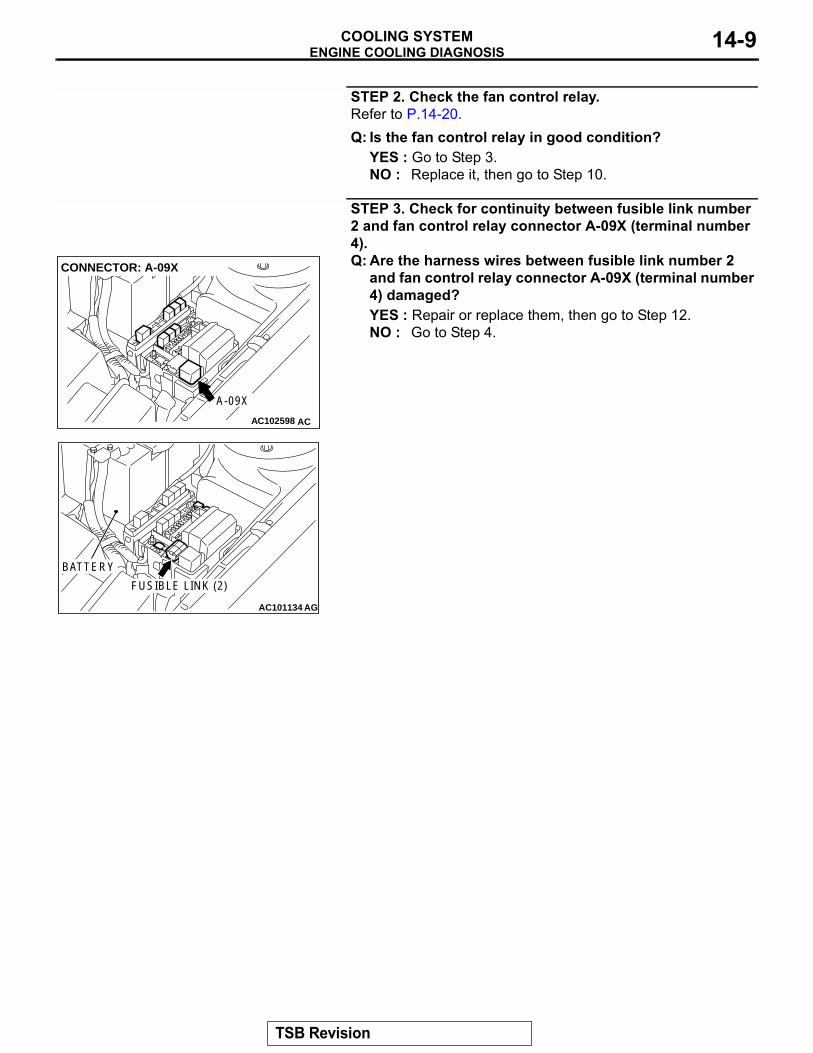
STEP 2. Check the fan control relay.Refer to P.14-20.Q: Is the fan control relay in good condition?
YES : Go to Step 3.NO : Replace it, then go to Step 10.
STEP 3. Check for continuity between fusible link number 2 and fan control relay connector A-09X (terminal number 4).Q: Are the harness wires between fusible link number 2
and fan control relay connector A-09X (terminal number 4) damaged? YES : Repair or replace them, then go to Step 12.NO : Go to Step 4.
AC102598
CONNECTOR: A-09X
A-09X
AC
AC101134
BATTERY
FUSIBLE LINK (2)
AG
TSB Revision
ENGINE COOLING DIAGNOSISCOOLING SYSTEM14-10
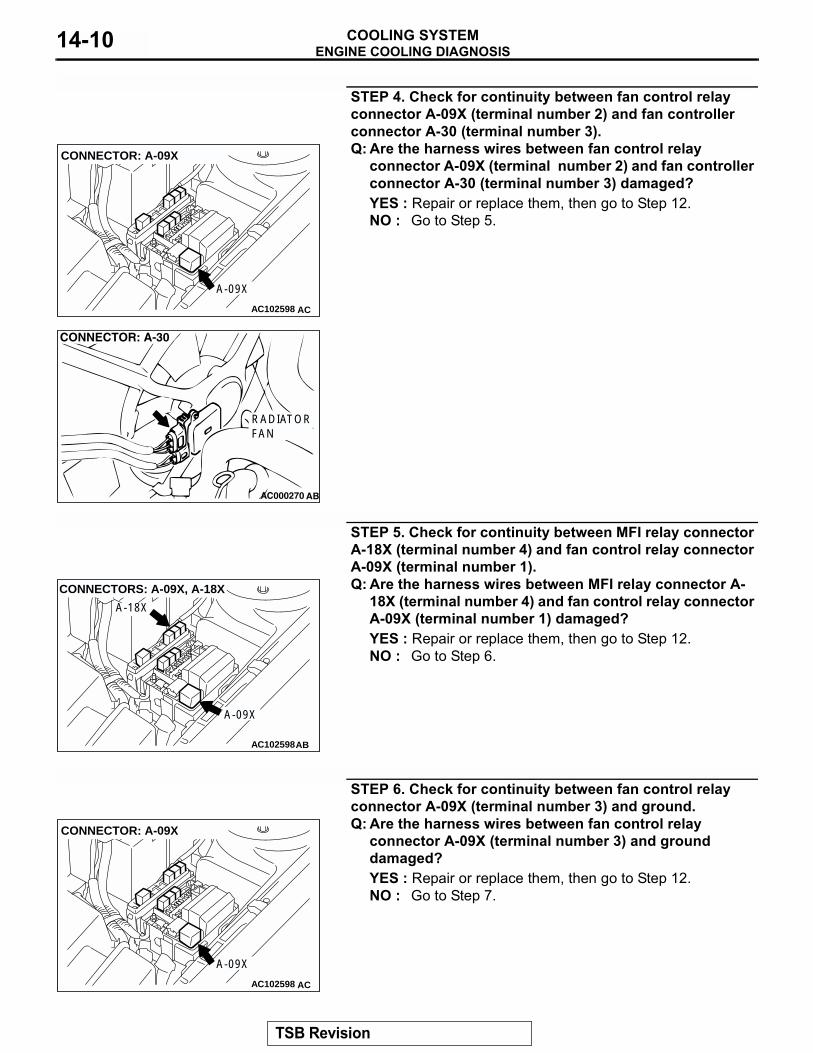
STEP 4. Check for continuity between fan control relay connector A-09X (terminal number 2) and fan controller connector A-30 (terminal number 3).Q: Are the harness wires between fan control relay
connector A-09X (terminal number 2) and fan controller connector A-30 (terminal number 3) damaged?YES : Repair or replace them, then go to Step 12.NO : Go to Step 5.
STEP 5. Check for continuity between MFI relay connector A-18X (terminal number 4) and fan control relay connector A-09X (terminal number 1).Q: Are the harness wires between MFI relay connector A-
18X (terminal number 4) and fan control relay connector A-09X (terminal number 1) damaged?YES : Repair or replace them, then go to Step 12.NO : Go to Step 6.
STEP 6. Check for continuity between fan control relay connector A-09X (terminal number 3) and ground.Q: Are the harness wires between fan control relay
connector A-09X (terminal number 3) and ground damaged?YES : Repair or replace them, then go to Step 12.NO : Go to Step 7.
AC102598
CONNECTOR: A-09X
A-09X
AC
AC000270 AB
CONNECTOR: A-30
RADIATORFAN
AC102598
CONNECTORS: A-09X, A-18X
A-18X
A-09X
AB
AC102598
CONNECTOR: A-09X
A-09X
AC
TSB Revision
ENGINE COOLING DIAGNOSISCOOLING SYSTEM 14-11
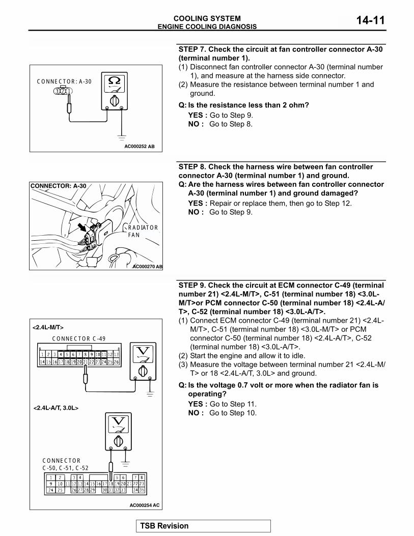
STEP 7. Check the circuit at fan controller connector A-30 (terminal number 1).(1) Disconnect fan controller connector A-30 (terminal number
1), and measure at the harness side connector.(2) Measure the resistance between terminal number 1 and
ground.Q: Is the resistance less than 2 ohm?
YES : Go to Step 9.NO : Go to Step 8.
STEP 8. Check the harness wire between fan controller connector A-30 (terminal number 1) and ground.Q: Are the harness wires between fan controller connector
A-30 (terminal number 1) and ground damaged?YES : Repair or replace them, then go to Step 12.NO : Go to Step 9.
STEP 9. Check the circuit at ECM connector C-49 (terminal number 21) <2.4L-M/T>, C-51 (terminal number 18) <3.0L-M/T>or PCM connector C-50 (terminal number 18) <2.4L-A/T>, C-52 (terminal number 18) <3.0L-A/T>.(1) Connect ECM connector C-49 (terminal number 21) <2.4L-
M/T>, C-51 (terminal number 18) <3.0L-M/T> or PCM connector C-50 (terminal number 18) <2.4L-A/T>, C-52 (terminal number 18) <3.0L-A/T>.
(2) Start the engine and allow it to idle.(3) Measure the voltage between terminal number 21 <2.4L-M/
T> or 18 <2.4L-A/T, 3.0L> and ground.Q: Is the voltage 0.7 volt or more when the radiator fan is
operating?YES : Go to Step 11.NO : Go to Step 10.
AC000252 AB
CONNECTOR: A-30
AC000270 AB
CONNECTOR: A-30
RADIATORFAN
AC000254
CONNECTOR C-49
CONNECTOR C-50, C-51, C-52
<2.4L-M/T>
<2.4L-A/T, 3.0L>
AC
TSB Revision
ENGINE COOLING DIAGNOSISCOOLING SYSTEM14-12
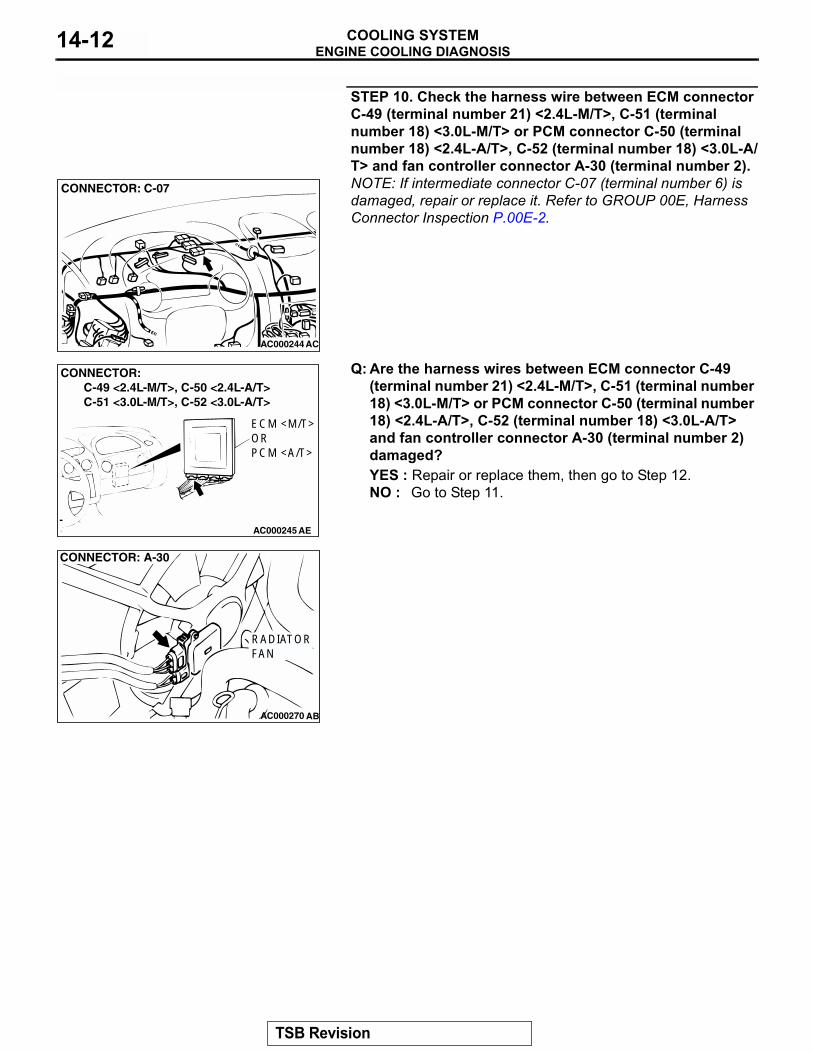
STEP 10. Check the harness wire between ECM connector C-49 (terminal number 21) <2.4L-M/T>, C-51 (terminal number 18) <3.0L-M/T> or PCM connector C-50 (terminal number 18) <2.4L-A/T>, C-52 (terminal number 18) <3.0L-A/T> and fan controller connector A-30 (terminal number 2).NOTE: If intermediate connector C-07 (terminal number 6) is damaged, repair or replace it. Refer to GROUP 00E, Harness Connector Inspection P.00E-2.
Q: Are the harness wires between ECM connector C-49 (terminal number 21) <2.4L-M/T>, C-51 (terminal number 18) <3.0L-M/T> or PCM connector C-50 (terminal number 18) <2.4L-A/T>, C-52 (terminal number 18) <3.0L-A/T> and fan controller connector A-30 (terminal number 2) damaged?YES : Repair or replace them, then go to Step 12.NO : Go to Step 11.
AC000244
CONNECTOR: C-07
AC
AC000245 AE
CONNECTOR: C-49 <2.4L-M/T>, C-50 <2.4L-A/T> C-51 <3.0L-M/T>, C-52 <3.0L-A/T>
ECM <M/T>ORPCM <A/T>
AC000270 AB
CONNECTOR: A-30
RADIATORFAN
TSB Revision
ENGINE COOLING DIAGNOSISCOOLING SYSTEM 14-13
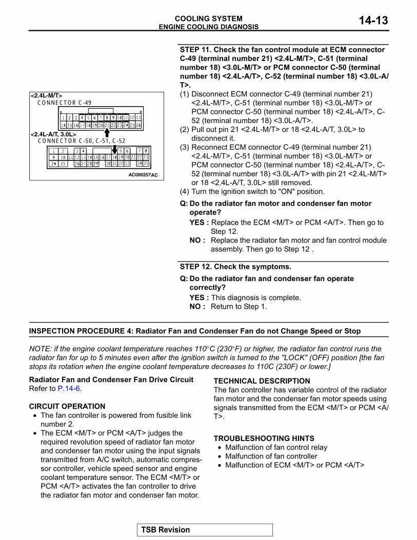
STEP 11. Check the fan control module at ECM connector C-49 (terminal number 21) <2.4L-M/T>, C-51 (terminal number 18) <3.0L-M/T> or PCM connector C-50 (terminal number 18) <2.4L-A/T>, C-52 (terminal number 18) <3.0L-A/T>.(1) Disconnect ECM connector C-49 (terminal number 21)
<2.4L-M/T>, C-51 (terminal number 18) <3.0L-M/T> or PCM connector C-50 (terminal number 18) <2.4L-A/T>, C-52 (terminal number 18) <3.0L-A/T>.
(2) Pull out pin 21 <2.4L-M/T> or 18 <2.4L-A/T, 3.0L> to disconnect it.
(3) Reconnect ECM connector C-49 (terminal number 21) <2.4L-M/T>, C-51 (terminal number 18) <3.0L-M/T> or PCM connector C-50 (terminal number 18) <2.4L-A/T>, C-52 (terminal number 18) <3.0L-A/T> with pin 21 <2.4L-M/T> or 18 <2.4L-A/T, 3.0L> still removed.
(4) Turn the ignition switch to "ON" position.Q: Do the radiator fan motor and condenser fan motor
operate?YES : Replace the ECM <M/T> or PCM <A/T>. Then go to
Step 12.NO : Replace the radiator fan motor and fan control module
assembly. Then go to Step 12 .
STEP 12. Check the symptoms.Q: Do the radiator fan and condenser fan operate
correctly?YES : This diagnosis is complete.NO : Return to Step 1.
INSPECTION PROCEDURE 4: Radiator Fan and Condenser Fan do not Change Speed or Stop
NOTE: if the engine coolant temperature reaches 110°C (230°F) or higher, the radiator fan control runs the radiator fan for up to 5 minutes even after the ignition switch is turned to the "LOCK" (OFF) position [the fan stops its rotation when the engine coolant temperature decreases to 110C (230F) or lower.].
Radiator Fan and Condenser Fan Drive CircuitRefer to P.14-6..
CIRCUIT OPERATION• The fan controller is powered from fusible link
number 2.• The ECM <M/T> or PCM <A/T> judges the
required revolution speed of radiator fan motor and condenser fan motor using the input signals transmitted from A/C switch, automatic compres-sor controller, vehicle speed sensor and engine coolant temperature sensor. The ECM <M/T> or PCM <A/T> activates the fan controller to drive the radiator fan motor and condenser fan motor.
.
TECHNICAL DESCRIPTIONThe fan controller has variable control of the radiator fan motor and the condenser fan motor speeds using signals transmitted from the ECM <M/T> or PCM <A/T>..
TROUBLESHOOTING HINTS• Malfunction of fan control relay• Malfunction of fan controller• Malfunction of ECM <M/T> or PCM <A/T>
.
AC000257
<2.4L-M/T>
<2.4L-A/T, 3.0L>
CONNECTOR C-49
CONNECTOR C-50, C-51, C-52
AC
TSB Revision
ENGINE COOLING DIAGNOSISCOOLING SYSTEM14-14
DIAGNOSISRequired Special Tool:MB991223: Harness SetSTEP 1. Check the fan control relay.Refer to P.14-20.Q: Is the fan control relay in good condition?
YES : Go to Step 2.NO : Replace the part, then go to Step 6.
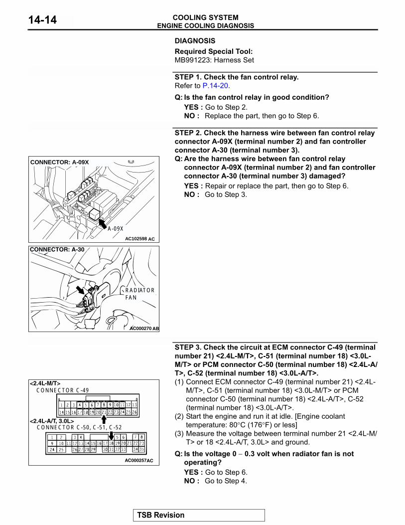
STEP 2. Check the harness wire between fan control relay connector A-09X (terminal number 2) and fan controller connector A-30 (terminal number 3).Q: Are the harness wire between fan control relay
connector A-09X (terminal number 2) and fan controller connector A-30 (terminal number 3) damaged?YES : Repair or replace the part, then go to Step 6.NO : Go to Step 3.
STEP 3. Check the circuit at ECM connector C-49 (terminal number 21) <2.4L-M/T>, C-51 (terminal number 18) <3.0L-M/T> or PCM connector C-50 (terminal number 18) <2.4L-A/T>, C-52 (terminal number 18) <3.0L-A/T>.(1) Connect ECM connector C-49 (terminal number 21) <2.4L-
M/T>, C-51 (terminal number 18) <3.0L-M/T> or PCM connector C-50 (terminal number 18) <2.4L-A/T>, C-52 (terminal number 18) <3.0L-A/T>.
(2) Start the engine and run it at idle. [Engine coolant temperature: 80°C (176°F) or less]
(3) Measure the voltage between terminal number 21 <2.4L-M/T> or 18 <2.4L-A/T, 3.0L> and ground.
Q: Is the voltage 0 − 0.3 volt when radiator fan is not operating?YES : Go to Step 6.NO : Go to Step 4.
AC102598
CONNECTOR: A-09X
A-09X
AC
AC000270 AB
CONNECTOR: A-30
RADIATORFAN
AC000257
<2.4L-M/T>
<2.4L-A/T, 3.0L>
CONNECTOR C-49
CONNECTOR C-50, C-51, C-52
AC
TSB Revision
ENGINE COOLING DIAGNOSISCOOLING SYSTEM 14-15
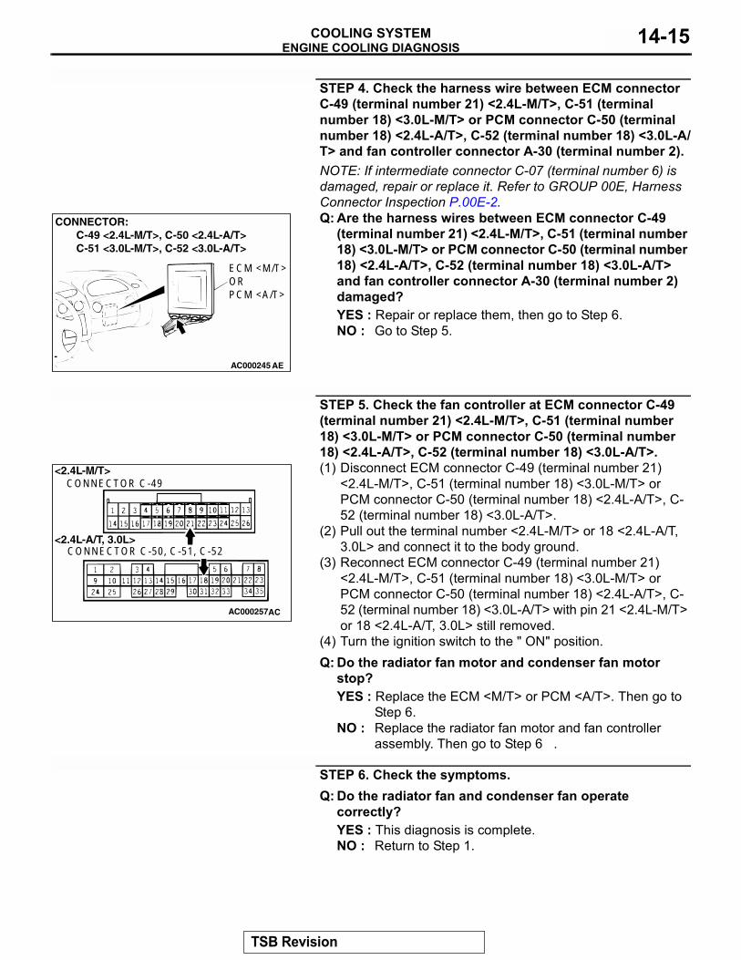
STEP 4. Check the harness wire between ECM connector C-49 (terminal number 21) <2.4L-M/T>, C-51 (terminal number 18) <3.0L-M/T> or PCM connector C-50 (terminal number 18) <2.4L-A/T>, C-52 (terminal number 18) <3.0L-A/T> and fan controller connector A-30 (terminal number 2).NOTE: If intermediate connector C-07 (terminal number 6) is damaged, repair or replace it. Refer to GROUP 00E, Harness Connector Inspection P.00E-2.Q: Are the harness wires between ECM connector C-49
(terminal number 21) <2.4L-M/T>, C-51 (terminal number 18) <3.0L-M/T> or PCM connector C-50 (terminal number 18) <2.4L-A/T>, C-52 (terminal number 18) <3.0L-A/T> and fan controller connector A-30 (terminal number 2) damaged?YES : Repair or replace them, then go to Step 6.NO : Go to Step 5.
STEP 5. Check the fan controller at ECM connector C-49 (terminal number 21) <2.4L-M/T>, C-51 (terminal number 18) <3.0L-M/T> or PCM connector C-50 (terminal number 18) <2.4L-A/T>, C-52 (terminal number 18) <3.0L-A/T>.(1) Disconnect ECM connector C-49 (terminal number 21)
<2.4L-M/T>, C-51 (terminal number 18) <3.0L-M/T> or PCM connector C-50 (terminal number 18) <2.4L-A/T>, C-52 (terminal number 18) <3.0L-A/T>.
(2) Pull out the terminal number <2.4L-M/T> or 18 <2.4L-A/T, 3.0L> and connect it to the body ground.
(3) Reconnect ECM connector C-49 (terminal number 21) <2.4L-M/T>, C-51 (terminal number 18) <3.0L-M/T> or PCM connector C-50 (terminal number 18) <2.4L-A/T>, C-52 (terminal number 18) <3.0L-A/T> with pin 21 <2.4L-M/T> or 18 <2.4L-A/T, 3.0L> still removed.
(4) Turn the ignition switch to the " ON" position.Q: Do the radiator fan motor and condenser fan motor
stop?YES : Replace the ECM <M/T> or PCM <A/T>. Then go to
Step 6.NO : Replace the radiator fan motor and fan controller
assembly. Then go to Step 6 .
STEP 6. Check the symptoms.Q: Do the radiator fan and condenser fan operate
correctly?YES : This diagnosis is complete.NO : Return to Step 1.
AC000245 AE
CONNECTOR: C-49 <2.4L-M/T>, C-50 <2.4L-A/T> C-51 <3.0L-M/T>, C-52 <3.0L-A/T>
ECM <M/T>ORPCM <A/T>
AC000257
<2.4L-M/T>
<2.4L-A/T, 3.0L>
CONNECTOR C-49
CONNECTOR C-50, C-51, C-52
AC
TSB Revision
ENGINE COOLING DIAGNOSISCOOLING SYSTEM14-16
INSPECTION PROCEDURE 5: Radiator Fan does not Operate.
TECHNICAL DESCRIPTIONThe cause could be a malfunction of the radiator fan motor or an open circuit between the fan controller and the radiator fan motor.
.
TROUBLESHOOTING HINTS• Malfunction of radiator fan motor• Malfunction of fan controller
.
DIAGNOSISReplace the radiator fan motor and fan controller assembly.Q: Does the radiator fan operate correctly?
YES : There is no action to be taken?NO : Repair the wiring harness between the fan controller
and the radiator fan motor.
INSPECTION PROCEDURE 6: Condenser Fan does not Operate.
Radiator Fan and Condenser Fan Drive CircuitRefer to P.14-6..
CIRCUIT OPERATION• The fan controller is powered from fusible link
number 2.• The ECM <M/T> or PCM <A/T> judges the
required revolution speed of radiator fan motor and condenser fan motor using the input signals transmitted from A/C switch, automatic compres-sor controller, vehicle speed sensor and engine coolant temperature sensor. The ECM <M/T> or PCM <A/T> activates the fan controller to drive the radiator fan motor and condenser fan motor.
.
TECHNICAL DESCRIPTIONThe cause could be a malfunction of the condenser fan motor or of the fan controller..
TROUBLESHOOTING HINTS• Malfunction of condenser fan motor• Malfunction of fan controller
.
DIAGNOSIS
STEP 1. Check the condenser fan motor.Refer to GROUP 55, Condenser and Condenser Fan Motor P.55-51.Q: Is the condenser fan in good condition?
YES : Go to Step 2.NO : Replace the fan motor, then go to Step 3.
STEP 2. Check the fan controller.Refer to P.14-19.Q: Is the fan controller in good condition?
YES : Go to Step 3.NO : Replace the fan controller, then go to Step 3.
STEP 3. Check the symptoms.Q: Does the condenser fan operate correctly?
YES : This diagnosis is complete.NO : Return to Step1.
TSB Revision
ON-VEHICLE SERVICECOOLING SYSTEM 14-17
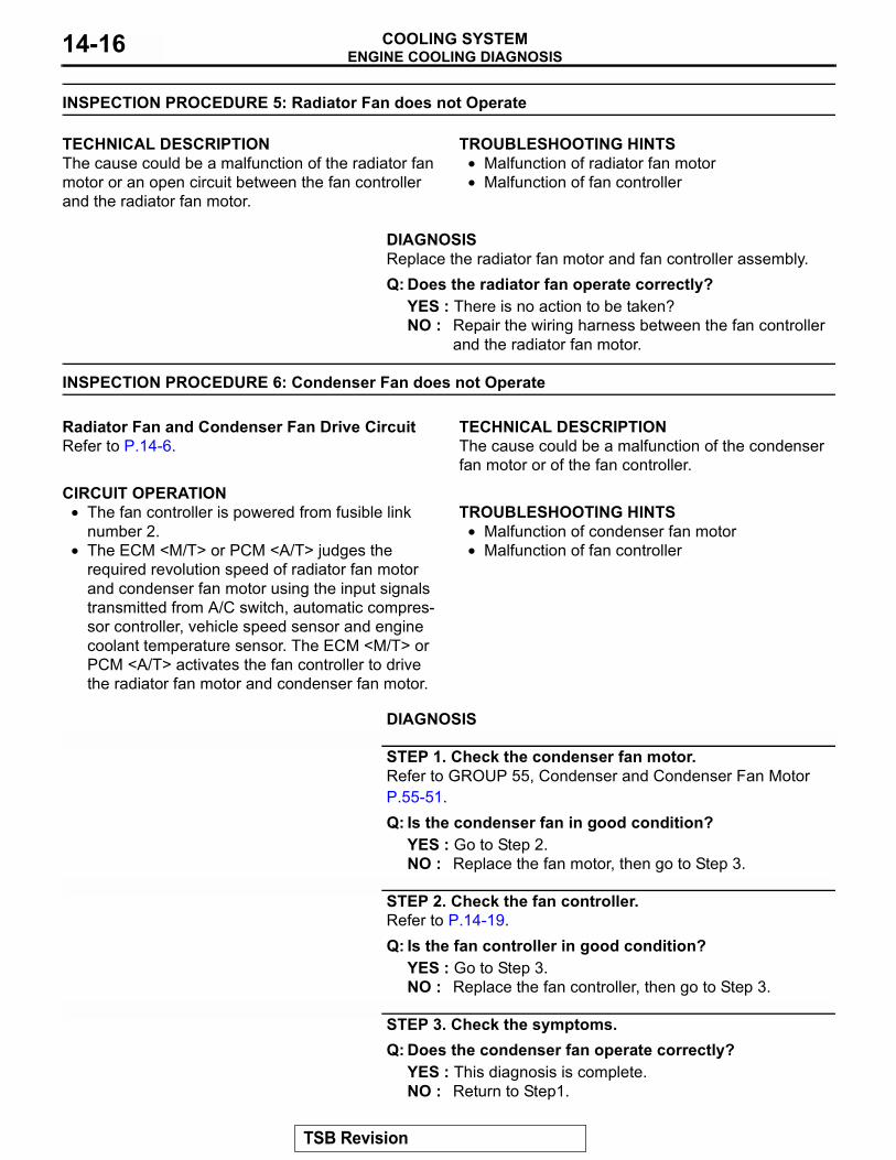
ON-VEHICLE SERVICEENGINE COOLANT LEAK CHECK
M1141001000173
WARNINGWhen pressure testing the cooling system, slowly release cooling system pressure to avoid getting burned by hot coolant.
CAUTION• Be sure to completely clean away any moisture from
the places checked.• When the tester is taken out, be careful not to spill any
coolant from it.• Be careful when installing and removing the tester and
when testing not to deform the filler neck of the radia-tor.
1. Check that the coolant level is up to the filler neck. Install a radiator cap tester and apply 160 kPa (23 psi) pressure, and then check for leakage from the radiator hose or connections.
2. If there is leakage, repair or replace the appropriate part.
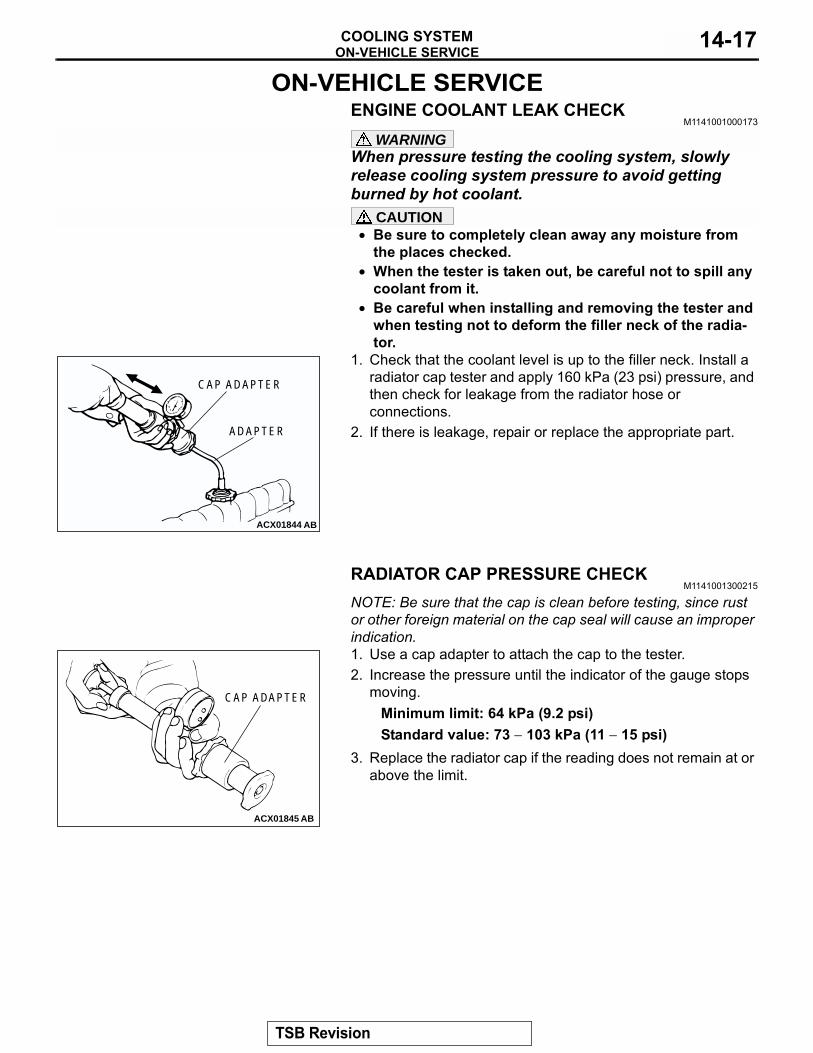
RADIATOR CAP PRESSURE CHECKM1141001300215
NOTE: Be sure that the cap is clean before testing, since rust or other foreign material on the cap seal will cause an improper indication.1. Use a cap adapter to attach the cap to the tester.2. Increase the pressure until the indicator of the gauge stops
moving.Minimum limit: 64 kPa (9.2 psi)Standard value: 73 − 103 kPa (11 − 15 psi)
3. Replace the radiator cap if the reading does not remain at or above the limit.
ACX01844 AB
CAP ADAPTER
ADAPTER
ACX01845 AB
CAP ADAPTER
TSB Revision
ON-VEHICLE SERVICECOOLING SYSTEM14-18
ENGINE COOLANT REPLACEMENTM1141001200229
1. Turn the ignition switch to the "ON" position, and then rotate the heater control to the "MAX HOT" position.
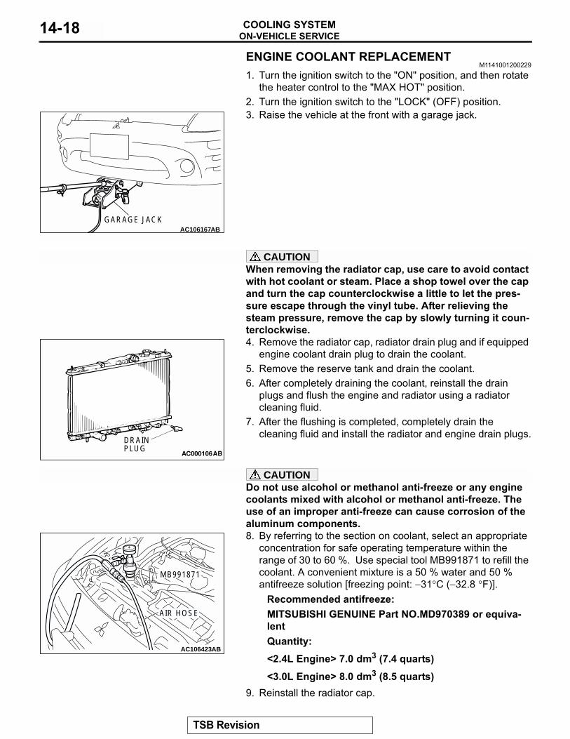
2. Turn the ignition switch to the "LOCK" (OFF) position.3. Raise the vehicle at the front with a garage jack.
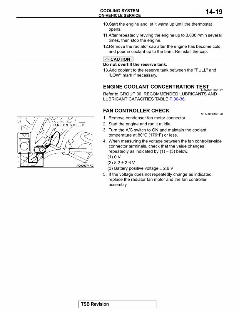
CAUTIONWhen removing the radiator cap, use care to avoid contact with hot coolant or steam. Place a shop towel over the cap and turn the cap counterclockwise a little to let the pres-sure escape through the vinyl tube. After relieving the steam pressure, remove the cap by slowly turning it coun-terclockwise.4. Remove the radiator cap, radiator drain plug and if equipped
engine coolant drain plug to drain the coolant.5. Remove the reserve tank and drain the coolant.6. After completely draining the coolant, reinstall the drain
plugs and flush the engine and radiator using a radiator cleaning fluid.
7. After the flushing is completed, completely drain the cleaning fluid and install the radiator and engine drain plugs.
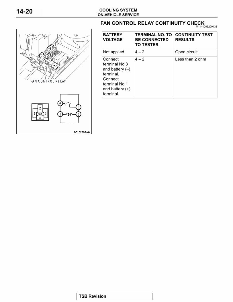
CAUTIONDo not use alcohol or methanol anti-freeze or any engine coolants mixed with alcohol or methanol anti-freeze. The use of an improper anti-freeze can cause corrosion of the aluminum components.8. By referring to the section on coolant, select an appropriate
concentration for safe operating temperature within the range of 30 to 60 %. Use special tool MB991871 to refill the coolant. A convenient mixture is a 50 % water and 50 % antifreeze solution [freezing point: −31°C (−32.8 °F)].
Recommended antifreeze:MITSUBISHI GENUINE Part NO.MD970389 or equiva-lentQuantity:<2.4L Engine> 7.0 dm3 (7.4 quarts)<3.0L Engine> 8.0 dm3 (8.5 quarts)
9. Reinstall the radiator cap.
AC106167GARAGE JACK
AB
AC000106
DRAINPLUG
AB
AC106423AB
MB991871
AIR HOSE
TSB Revision
ON-VEHICLE SERVICECOOLING SYSTEM 14-19
10.Start the engine and let it warm up until the thermostat opens.
11.After repeatedly revving the engine up to 3,000 r/min several times, then stop the engine.
12.Remove the radiator cap after the engine has become cold, and pour in coolant up to the brim. Reinstall the cap.
CAUTIONDo not overfill the reserve tank.13.Add coolant to the reserve tank between the "FULL" and
"LOW" mark if necessary.
ENGINE COOLANT CONCENTRATION TESTM1141001100192
Refer to GROUP 00, RECOMMENDED LUBRICANTS AND LUBRICANT CAPACITIES TABLE P.00-36.
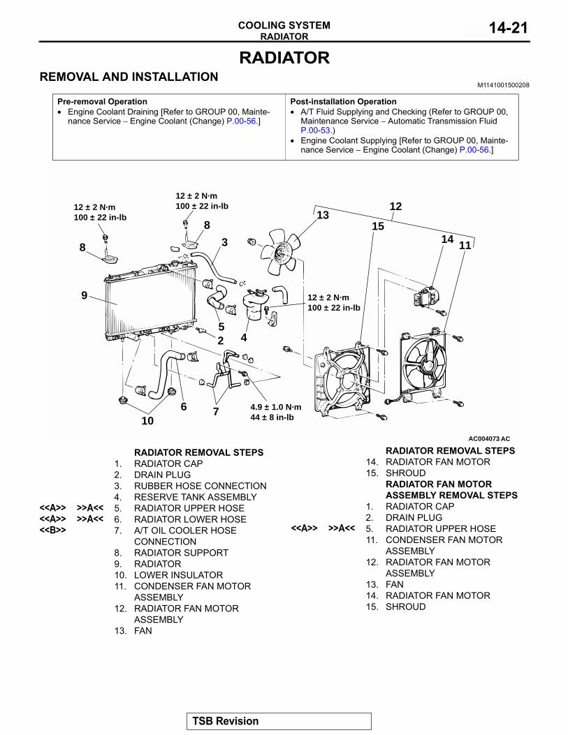
FAN CONTROLLER CHECKM1141006100120
1. Remove condenser fan motor connector.2. Start the engine and run it at idle.3. Turn the A/C switch to ON and maintain the coolant
temperature at 80°C (176°F) or less.4. When measuring the voltage between the fan controller-side
connector terminals, check that the value changes repeatedly as indicated by (1) − (3) below.(1) 0 V(2) 8.2 ± 2.6 V(3) Battery positive voltage ± 2.6 V
5. If the voltage does not repeatedly change as indicated, replace the radiator fan motor and the fan controller assembly.
AC000274AC
FAN CONTROLLER
TSB Revision
ON-VEHICLE SERVICECOOLING SYSTEM14-20
FAN CONTROL RELAY CONTINUITY CHECKM1141006200138
BATTERY VOLTAGE
TERMINAL NO. TO BE CONNECTED TO TESTER
CONTINUITY TEST RESULTS
Not applied 4 − 2 Open circuit
Connect terminal No.3 and battery (−) terminal.Connect terminal No.1 and battery (+) terminal.
4 − 2 Less than 2 ohm
AC102593
FAN CONTROL RELAY
AB
TSB Revision
RADIATORCOOLING SYSTEM 14-21
RADIATORREMOVAL AND INSTALLATION
M1141001500208
Pre-removal Operation• Engine Coolant Draining [Refer to GROUP 00, Mainte-
nance Service − Engine Coolant (Change) P.00-56.]
Post-installation Operation• A/T Fluid Supplying and Checking (Refer to GROUP 00,
Maintenance Service − Automatic Transmission Fluid P.00-53.)
• Engine Coolant Supplying [Refer to GROUP 00, Mainte-nance Service − Engine Coolant (Change) P.00-56.]
AC004073
11
1213
14158
8 3
52 4
9
106 7
AC
12 ± 2 N·m100 ± 22 in-lb
12 ± 2 N·m100 ± 22 in-lb
12 ± 2 N·m100 ± 22 in-lb
4.9 ± 1.0 N·m44 ± 8 in-lb
RADIATOR REMOVAL STEPS1. RADIATOR CAP2. DRAIN PLUG3. RUBBER HOSE CONNECTION4. RESERVE TANK ASSEMBLY
<<A>> >>A<< 5. RADIATOR UPPER HOSE<<A>> >>A<< 6. RADIATOR LOWER HOSE<<B>> 7. A/T OIL COOLER HOSE
CONNECTION 8. RADIATOR SUPPORT9. RADIATOR10. LOWER INSULATOR11. CONDENSER FAN MOTOR
ASSEMBLY 12. RADIATOR FAN MOTOR
ASSEMBLY13. FAN
14. RADIATOR FAN MOTOR15. SHROUD
RADIATOR FAN MOTOR ASSEMBLY REMOVAL STEPS
1. RADIATOR CAP2. DRAIN PLUG
<<A>> >>A<< 5. RADIATOR UPPER HOSE11. CONDENSER FAN MOTOR
ASSEMBLY 12. RADIATOR FAN MOTOR
ASSEMBLY13. FAN14. RADIATOR FAN MOTOR15. SHROUD
RADIATOR REMOVAL STEPS
TSB Revision
RADIATORCOOLING SYSTEM14-22
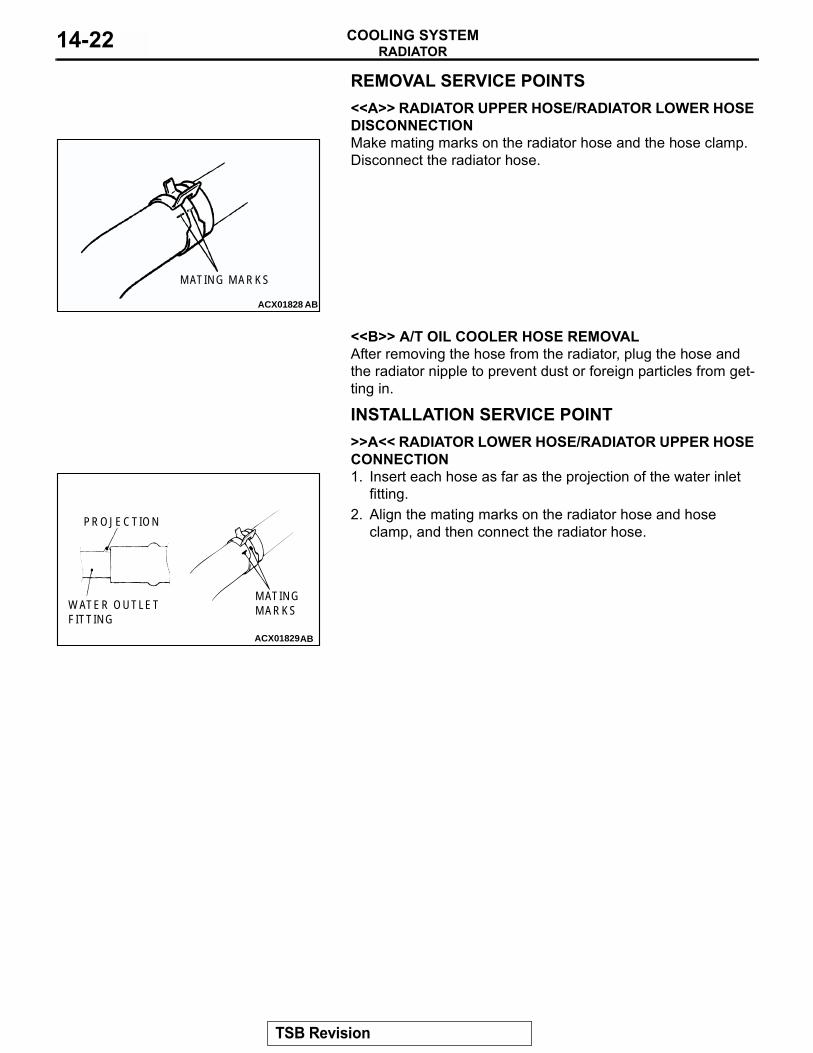
REMOVAL SERVICE POINTS.<<A>> RADIATOR UPPER HOSE/RADIATOR LOWER HOSE DISCONNECTIONMake mating marks on the radiator hose and the hose clamp. Disconnect the radiator hose.
.
<<B>> A/T OIL COOLER HOSE REMOVALAfter removing the hose from the radiator, plug the hose and the radiator nipple to prevent dust or foreign particles from get-ting in.
INSTALLATION SERVICE POINT.
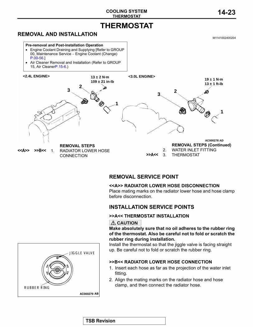
>>A<< RADIATOR LOWER HOSE/RADIATOR UPPER HOSE CONNECTION1. Insert each hose as far as the projection of the water inlet
fitting.2. Align the mating marks on the radiator hose and hose
clamp, and then connect the radiator hose.
ACX01828
MATING MARKS
AB
ACX01829AB
PROJECTION
WATER OUTLETFITTING
MATINGMARKS
TSB Revision
THERMOSTATCOOLING SYSTEM 14-23
THERMOSTATREMOVAL AND INSTALLATION
M1141002400204
REMOVAL SERVICE POINT.
<<A>> RADIATOR LOWER HOSE DISCONNECTIONPlace mating marks on the radiator lower hose and hose clamp before disconnection.
INSTALLATION SERVICE POINTS.
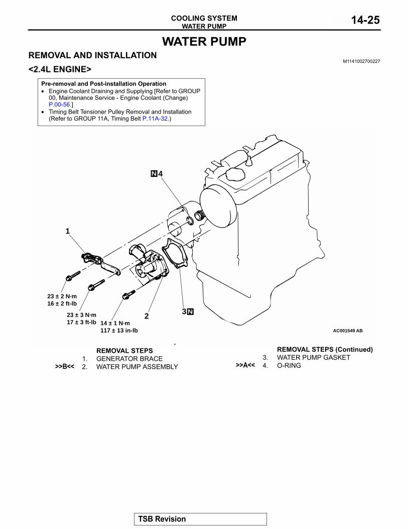
>>A<< THERMOSTAT INSTALLATIONCAUTION
Make absolutely sure that no oil adheres to the rubber ring of the thermostat. Also be careful not to fold or scratch the rubber ring during installation.Install the thermostat so that the jiggle valve is facing straight up. Be careful not to fold or scratch the rubber ring..
>>B<< RADIATOR LOWER HOSE CONNECTION1. Insert each hose as far as the projection of the water inlet
fitting.2. Align the mating marks on the radiator hose and hose
clamp, and then connect the radiator hose.
Pre-removal and Post-installation Operation• Engine Coolant Draining and Supplying [Refer to GROUP
00, Maintenance Service − Engine Coolant (Change) P.00-56.]
• Air Cleaner Removal and Installation (Refer to GROUP 15, Air CleanerP.15-6.)
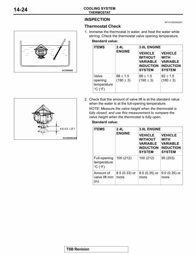
AC000278
23
1
19 ± 1 N·m13 ± 1 ft-lb
13 ± 2 N·m109 ± 21 in-lb
1
23
AD
<2.4L ENGINE> <3.0L ENGINE>
REMOVAL STEPS<<A>> >>B<< 1. RADIATOR LOWER HOSE
CONNECTION2. WATER INLET FITTING
>>A<< 3. THERMOSTAT
REMOVAL STEPS (Continued)
AC000279
JIGGLE VALVE
RUBBER RING
AB
TSB Revision
THERMOSTATCOOLING SYSTEM14-24
INSPECTIONM1141002500201
Thermostat Check1. Immerse the thermostat in water, and heat the water while
stirring. Check the thermostat valve opening temperature.Standard value:
2. Check that the amount of valve lift is at the standard value when the water is at the full-opening temperature.NOTE: Measure the valve height when the thermostat is fully closed, and use this measurement to compare the valve height when the thermostat is fully open.
Standard value:
ITEMS 2.4L ENGINE
3.0L ENGINEVEHICLE WITHOUT VARIABLE INDUCTION SYSTEM
VEHICLE WITH VARIABLE INDUCTION SYSTEM
Valve opening temperature °C (°F)
88 ± 1.5(190 ± 3)
88 ± 1.5(190 ± 3)
82 ± 1.5(180 ± 3)
ITEMS 2.4L ENGINE
3.0L ENGINEVEHICLE WITHOUT VARIABLE INDUCTION SYSTEM
VEHICLE WITH VARIABLE INDUCTION SYSTEM
Full-opening temperature °C (°F)
100 (212) 100 (212) 95 (203)
Amount of valve lift mm (in)
8.5 (0.33) or more
9.0 (0.35) or more
9.0 (0.35) or more
ACX00400
ACX00401AB
VALVE LIFT
TSB Revision
WATER PUMPCOOLING SYSTEM 14-25
WATER PUMPREMOVAL AND INSTALLATION
M1141002700227
<2.4L ENGINE>Pre-removal and Post-installation Operation• Engine Coolant Draining and Supplying [Refer to GROUP
00, Maintenance Service - Engine Coolant (Change) P.00-56.]
• Timing Belt Tensioner Pulley Removal and Installation (Refer to GROUP 11A, Timing Belt P.11A-32.)
AC001549
23 ± 2 N·m16 ± 2 ft-lb
23 ± 3 N·m17 ± 3 ft-lb 14 ± 1 N·m
117 ± 13 in-lb
1
2 3
4N
N
AB
REMOVAL STEPS1. GENERATOR BRACE
>>B<< 2. WATER PUMP ASSEMBLY3. WATER PUMP GASKET
>>A<< 4. O-RING
REMOVAL STEPS (Continued)
TSB Revision
WATER PUMPCOOLING SYSTEM14-26
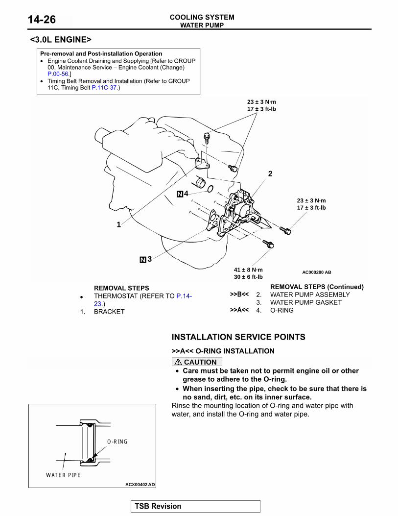
<3.0L ENGINE>
INSTALLATION SERVICE POINTS.
>>A<< O-RING INSTALLATIONCAUTION
• Care must be taken not to permit engine oil or other grease to adhere to the O-ring.
• When inserting the pipe, check to be sure that there is no sand, dirt, etc. on its inner surface.
Rinse the mounting location of O-ring and water pipe with water, and install the O-ring and water pipe.
Pre-removal and Post-installation Operation• Engine Coolant Draining and Supplying [Refer to GROUP
00, Maintenance Service − Engine Coolant (Change) P.00-56.]
• Timing Belt Removal and Installation (Refer to GROUP 11C, Timing Belt P.11C-37.)
AC000280
1
2
3
23 ± 3 N·m17 ± 3 ft-lb
23 ± 3 N·m17 ± 3 ft-lb
41 ± 8 N·m30 ± 6 ft-lb
AB
N
N 4
REMOVAL STEPS• THERMOSTAT (REFER TO P.14-
23.)1. BRACKET
>>B<< 2. WATER PUMP ASSEMBLY3. WATER PUMP GASKET
>>A<< 4. O-RING
REMOVAL STEPS (Continued)
ACX00402
O-RING
WATER PIPE
AD
TSB Revision
WATER PUMPCOOLING SYSTEM 14-27
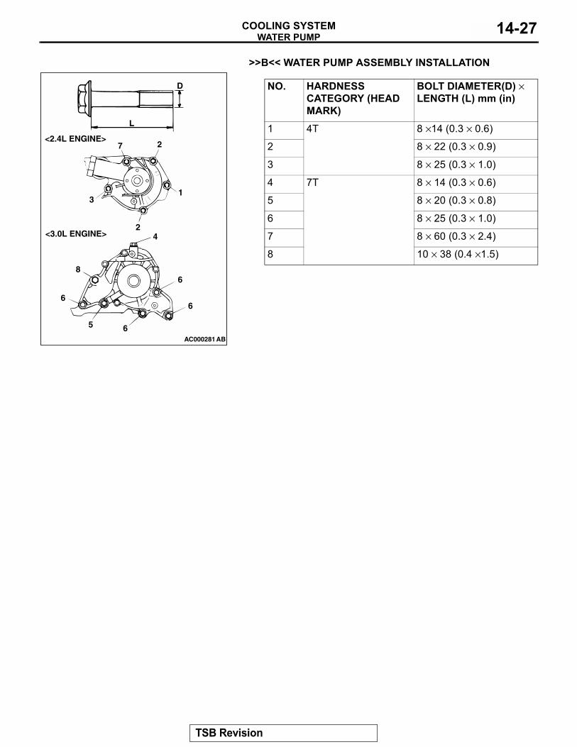
.
>>B<< WATER PUMP ASSEMBLY INSTALLATION
NO. HARDNESS CATEGORY (HEAD MARK)
BOLT DIAMETER(D) × LENGTH (L) mm (in)
1 4T 8 ×14 (0.3 × 0.6)
2 8 × 22 (0.3 × 0.9)
3 8 × 25 (0.3 × 1.0)
4 7T 8 × 14 (0.3 × 0.6)
5 8 × 20 (0.3 × 0.8)
6 8 × 25 (0.3 × 1.0)
7 8 × 60 (0.3 × 2.4)
8 10 × 38 (0.4 ×1.5)
AC000281
L
D
7 2
1
2
3
4
6
6
65
6
8
<3.0L ENGINE>
<2.4L ENGINE>
AB
TSB Revision
WATER HOSE AND WATER PIPECOOLING SYSTEM14-28
WATER HOSE AND WATER PIPEREMOVAL AND INSTALLATION
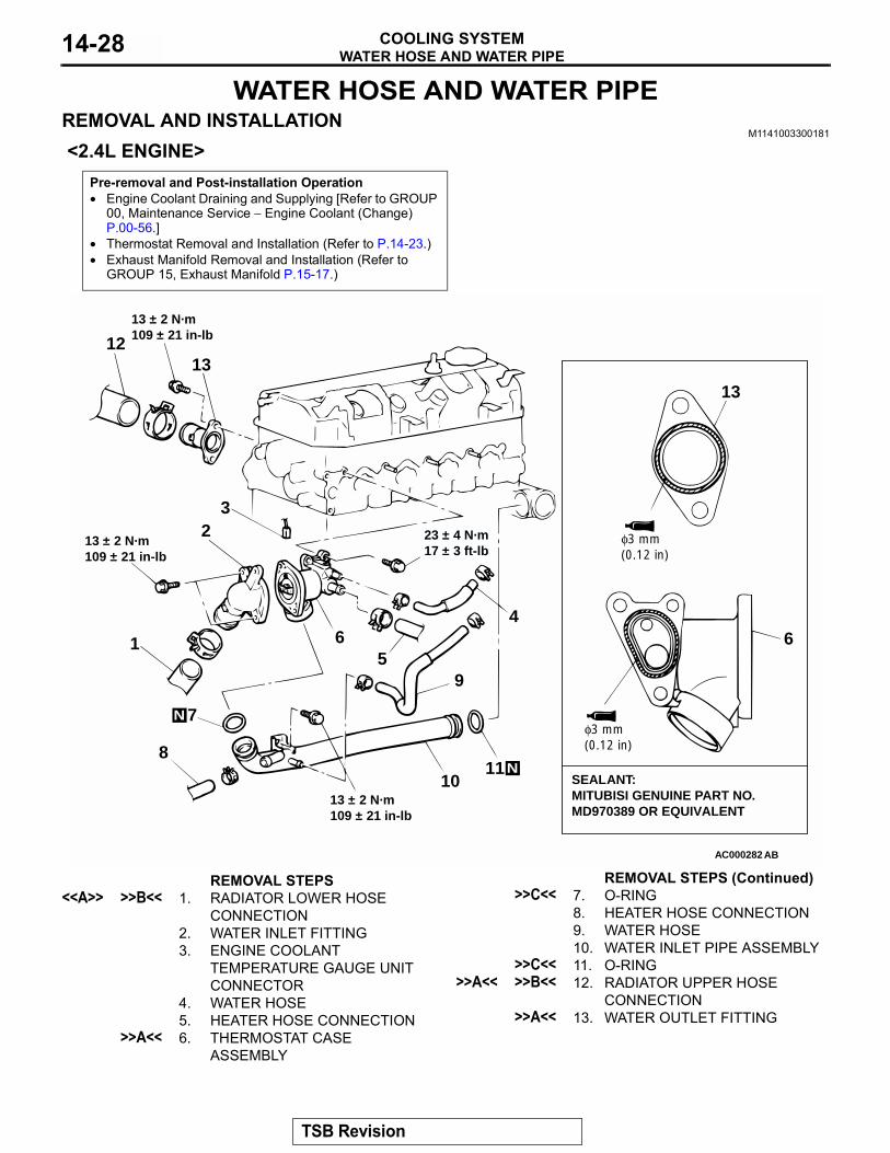
M1141003300181
<2.4L ENGINE>Pre-removal and Post-installation Operation• Engine Coolant Draining and Supplying [Refer to GROUP
00, Maintenance Service − Engine Coolant (Change) P.00-56.]
• Thermostat Removal and Installation (Refer to P.14-23.)• Exhaust Manifold Removal and Installation (Refer to
GROUP 15, Exhaust Manifold P.15-17.)
AC000282
SEALANT:MITUBISI GENUINE PART NO.MD970389 OR EQUIVALENT
64
11
95
1
23
8
7
6
1213
13
13 ± 2 N·m109 ± 21 in-lb
13 ± 2 N·m109 ± 21 in-lb
13 ± 2 N·m109 ± 21 in-lb
10
23 ± 4 N·m17 ± 3 ft-lb
AB
φ3 mm(0.12 in)
φ3 mm(0.12 in)
N
N
REMOVAL STEPS<<A>> >>B<< 1. RADIATOR LOWER HOSE
CONNECTION2. WATER INLET FITTING3. ENGINE COOLANT
TEMPERATURE GAUGE UNIT CONNECTOR
4. WATER HOSE5. HEATER HOSE CONNECTION
>>A<< 6. THERMOSTAT CASE ASSEMBLY
>>C<< 7. O-RING8. HEATER HOSE CONNECTION9. WATER HOSE10. WATER INLET PIPE ASSEMBLY
>>C<< 11. O-RING>>A<< >>B<< 12. RADIATOR UPPER HOSE
CONNECTION>>A<< 13. WATER OUTLET FITTING
REMOVAL STEPS (Continued)
TSB Revision
WATER HOSE AND WATER PIPECOOLING SYSTEM 14-29
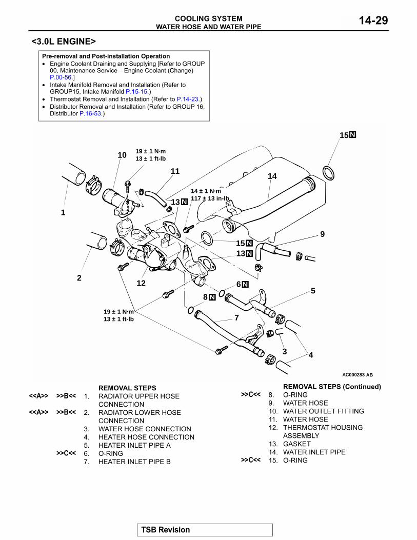
<3.0L ENGINE>Pre-removal and Post-installation Operation• Engine Coolant Draining and Supplying [Refer to GROUP
00, Maintenance Service − Engine Coolant (Change) P.00-56.]
• Intake Manifold Removal and Installation (Refer to GROUP15, Intake Manifold P.15-15.)
• Thermostat Removal and Installation (Refer to P.14-23.)• Distributor Removal and Installation (Refer to GROUP 16,
Distributor P.16-53.)
AC000283
1
2
3 4
56
7
8
9
10
11
12
13
14
1513
15
19 ± 1 N·m13 ± 1 ft-lb
19 ± 1 N·m13 ± 1 ft-lb
14 ± 1 N·m117 ± 13 in-lbN
N
N
N
N
N
AB
REMOVAL STEPS<<A>> >>B<< 1. RADIATOR UPPER HOSE
CONNECTION<<A>> >>B<< 2. RADIATOR LOWER HOSE
CONNECTION3. WATER HOSE CONNECTION4. HEATER HOSE CONNECTION5. HEATER INLET PIPE A
>>C<< 6. O-RING7. HEATER INLET PIPE B
>>C<< 8. O-RING9. WATER HOSE10. WATER OUTLET FITTING11. WATER HOSE12. THERMOSTAT HOUSING
ASSEMBLY13. GASKET14. WATER INLET PIPE
>>C<< 15. O-RING
REMOVAL STEPS (Continued)
TSB Revision
WATER HOSE AND WATER PIPECOOLING SYSTEM14-30
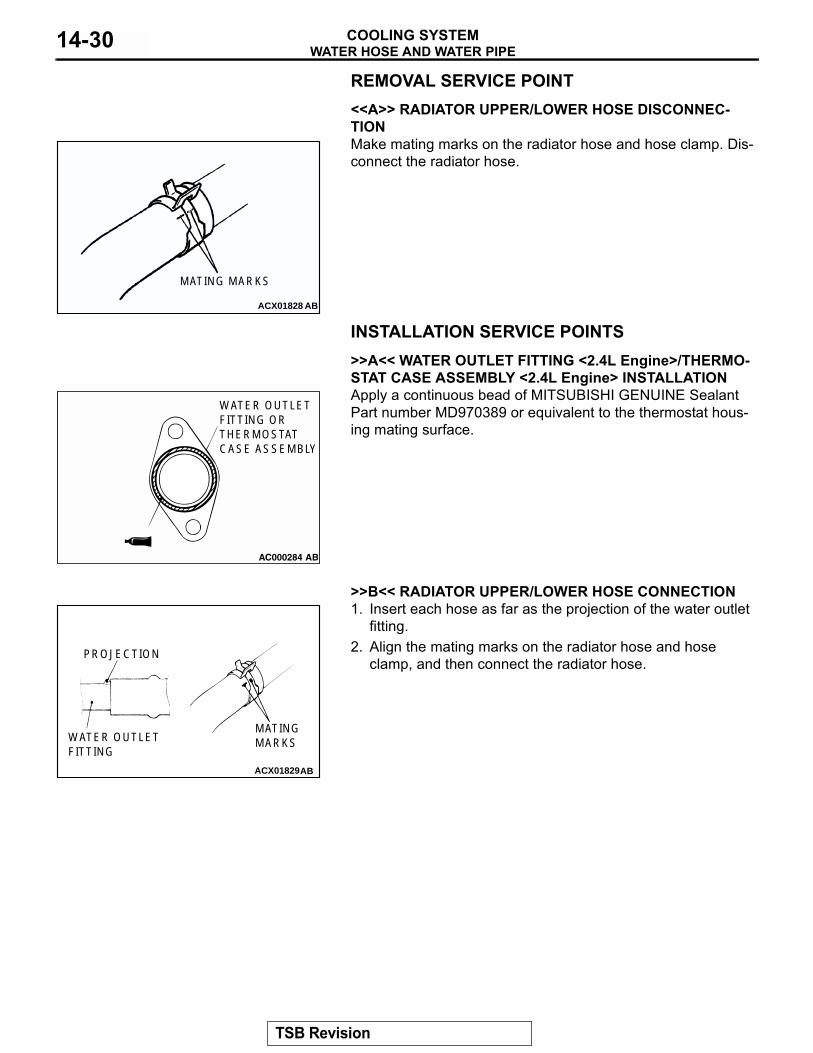
REMOVAL SERVICE POINT.<<A>> RADIATOR UPPER/LOWER HOSE DISCONNEC-TIONMake mating marks on the radiator hose and hose clamp. Dis-connect the radiator hose.
INSTALLATION SERVICE POINTS.
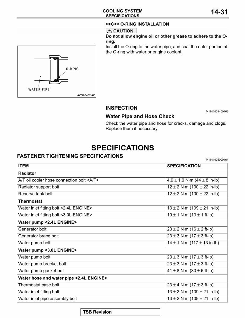
>>A<< WATER OUTLET FITTING <2.4L Engine>/THERMO-STAT CASE ASSEMBLY <2.4L Engine> INSTALLATIONApply a continuous bead of MITSUBISHI GENUINE Sealant Part number MD970389 or equivalent to the thermostat hous-ing mating surface.
.
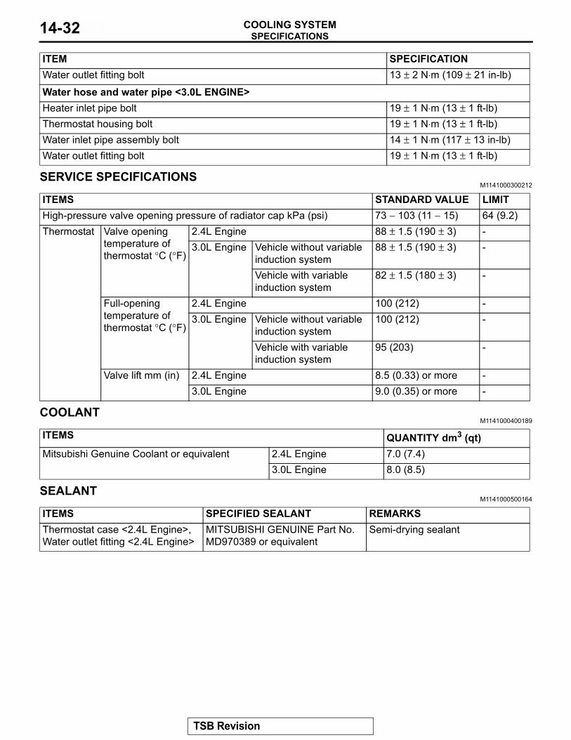
>>B<< RADIATOR UPPER/LOWER HOSE CONNECTION1. Insert each hose as far as the projection of the water outlet
fitting.2. Align the mating marks on the radiator hose and hose
clamp, and then connect the radiator hose.
.
ACX01828
MATING MARKS
AB
AC000284 AB
WATER OUTLETFITTING ORTHERMOSTATCASE ASSEMBLY
ACX01829AB
PROJECTION
WATER OUTLETFITTING
MATINGMARKS
TSB Revision
SPECIFICATIONSCOOLING SYSTEM 14-31
>>C<< O-RING INSTALLATIONCAUTION
Do not allow engine oil or other grease to adhere to the O-ring.Install the O-ring to the water pipe, and coat the outer portion of the O-ring with water or engine coolant.
INSPECTIONM1141003400166
Water Pipe and Hose CheckCheck the water pipe and hose for cracks, damage and clogs. Replace them if necessary.
SPECIFICATIONSFASTENER TIGHTENING SPECIFICATIONS
M1141005000164
ACX00402
O-RING
WATER PIPE
AD
ITEM SPECIFICATIONRadiatorA/T oil cooler hose connection bolt <A/T> 4.9 ± 1.0 N⋅m (44 ± 8 in-lb)Radiator support bolt 12 ± 2 N⋅m (100 ± 22 in-lb)Reserve tank bolt 12 ± 2 N⋅m (100 ± 22 in-lb)ThermostatWater inlet fitting bolt <2.4L ENGINE> 13 ± 2 N⋅m (109 ± 21 in-lb)Water inlet fitting bolt <3.0L ENGINE> 19 ± 1 N⋅m (13 ± 1 ft-lb)Water pump <2.4L ENGINE>Generator bolt 23 ± 2 N⋅m (16 ± 2 ft-lb)Generator brace bolt 23 ± 3 N⋅m (17 ± 3 ft-lb)Water pump bolt 14 ± 1 N⋅m (117 ± 13 in-lb)Water pump <3.0L ENGINE>Water pump bolt 23 ± 3 N⋅m (17 ± 3 ft-lb)Water pump bracket bolt 23 ± 3 N⋅m (17 ± 3 ft-lb)Water pump gasket bolt 41 ± 8 N⋅m (30 ± 6 ft-lb)Water hose and water pipe <2.4L ENGINE>Thermostat case bolt 23 ± 4 N⋅m (17 ± 3 ft-lb)Water inlet fitting bolt 13 ± 2 N⋅m (109 ± 21 in-lb)Water inlet pipe assembly bolt 13 ± 2 N⋅m (109 ± 21 in-lb)
TSB Revision
SPECIFICATIONSCOOLING SYSTEM14-32
SERVICE SPECIFICATIONSM1141000300212
COOLANTM1141000400189
SEALANTM1141000500164
Water outlet fitting bolt 13 ± 2 N⋅m (109 ± 21 in-lb)Water hose and water pipe <3.0L ENGINE>Heater inlet pipe bolt 19 ± 1 N⋅m (13 ± 1 ft-lb)Thermostat housing bolt 19 ± 1 N⋅m (13 ± 1 ft-lb)Water inlet pipe assembly bolt 14 ± 1 N⋅m (117 ± 13 in-lb)Water outlet fitting bolt 19 ± 1 N⋅m (13 ± 1 ft-lb)
ITEM SPECIFICATION
ITEMS STANDARD VALUE LIMITHigh-pressure valve opening pressure of radiator cap kPa (psi) 73 − 103 (11 − 15) 64 (9.2)Thermostat Valve opening
temperature of thermostat °C (°F)
2.4L Engine 88 ± 1.5 (190 ± 3) -3.0L Engine Vehicle without variable
induction system88 ± 1.5 (190 ± 3) -
Vehicle with variable induction system
82 ± 1.5 (180 ± 3) -
Full-opening temperature of thermostat °C (°F)
2.4L Engine 100 (212) -3.0L Engine Vehicle without variable
induction system100 (212) -
Vehicle with variable induction system
95 (203) -
Valve lift mm (in) 2.4L Engine 8.5 (0.33) or more -3.0L Engine 9.0 (0.35) or more -
ITEMS QUANTITY dm3 (qt)Mitsubishi Genuine Coolant or equivalent 2.4L Engine 7.0 (7.4)
3.0L Engine 8.0 (8.5)
ITEMS SPECIFIED SEALANT REMARKSThermostat case <2.4L Engine>, Water outlet fitting <2.4L Engine>
MITSUBISHI GENUINE Part No. MD970389 or equivalent
Semi-drying sealant
TSB Revision