Embed Size (px)
Citation preview

Mounding AnalysisEXAMPLES
Groundwater
Changi Wu/Lisa SchaeferNJDEP Division of Water Quality
SWMDR Training Day 2October 31, 2019

Introduction
• Demonstrate simple analysis• Demonstrate stretching the time interval• Demonstrate applicability to drainage pipes• Demonstrate calculating impacts to nearby
structures
Presentation Goals
2

Examples
1. No adverse hydraulic impact to groundwater2. Adverse hydraulic impact to groundwater and
adjustment of infiltration period3. Underground perforated pipe4. Drywell
3
Scenarios:

No adverse hydraulic impact to groundwater scenario
• A major development located in the coastal plain proposes an infiltration basin, whose bottom footprint measures 50 ft by 50 ft, to infiltrate 5,000 cf of runoff generated by the Water Quality Design Storm (WQDS). o The maximum depth of ponding water is designed to be
2 ft o Soil testing was performed in accordance with Appendix Eo The soil testing report shows that the Seasonal High Water
Table (SHWT) is 7.5 ft below the 6 in thick bottom sand layer of the basin
o The tested soil permeability rate of the most restrictive soil horizon below the basin is 4 in/hr
4

No adverse hydraulic impact to groundwater scenario
5
Step #1: Calculate the duration of infiltration period
Duration of infiltration period, t (hours)
= / /
Infiltration area = 50 ft 𝑥 50 ft 2,500 sf
Recharge Rate = ½ Tested Infiltration rate = 0.5 𝑥 4 in/hr 2 in/hr
Therefore, t
= , /, /
= 12 hr

No adverse hydraulic impact to groundwater scenarioStep #2: Prepare the inputs for the spreadsheet
6
Parameter Value
Recharge rate (R) 2 in/hr (4 ft/day)
Specific yield (Sy) 0.15
Horizontal hydraulic conductivity (Kh) 20 in/hr (40 ft/day)
½ length of basin (x direction) 25 ft
½ length of basin (y direction) 25 ft
Duration of infiltration period (t) 12 hr (0.5 days)
Initial thickness of saturated zone (hi(0)) 10 ft

No adverse hydraulic impact to groundwater scenarioStep #2: Input Section of the Hantush Spreadsheet
7

No adverse hydraulic impact to groundwater scenarioStep #2: Results Section of the Hantush Spreadsheet
8
SHWT

Adverse hydraulic impact to groundwater and adjustment of drain time scenario
• A major development located in the coastal plain proposes an infiltration basin, whose bottom footprint measures 88 ft by 88 ft, to infiltrate 15,000 cf of runoff generated by the 2-year design storm. o The maximum depth of ponding water is designed to be
2 ft
o Soil testing was performed in accordance with Appendix E
o The soil testing report shows that SHWT is 7.5 ft below the 6-in thick bottom sand layer of the basin
o The tested soil permeability rate of the most restrictive soil horizon below the basin is 4 in/hr
9

Adverse hydraulic impact to groundwater and adjustment of drain time scenarioStep #1: Calculate the duration of infiltration period
Duration of infiltration period, t (hours)
= / /
Infiltration area = 88 ft 𝑥 88 ft = 7,744 sf
Recharge rate = 0.5 𝑥 4 in/hr = 2 in/hr
Therefore, t = , /
, / = 11.62 hr
10

Adverse hydraulic impact to groundwater and adjustment of drain time scenarioStep #2: Prepare the inputs for the spreadsheet
11
Parameter Value
Recharge rate (R) 2 in/hr (4 ft/day)
Specific yield (Sy) 0.15
Horizontal hydraulic conductivity (Kh) 10 in/hr (20 ft/day)
½ length of basin (x direction) 44 ft
½ length of basin (y direction) 44 ft
Duration of infiltration period (t) 11.62 hr (0.48 days)
Initial thickness of saturated zone (hi(0)) 10 ft

Adverse hydraulic impact to groundwater and adjustment of drain time scenarioStep #2: Results Section of the Hantush Spreadsheet
12
SHWT

Adverse hydraulic impact to groundwater and adjustment of drain time scenarioStep #3: Adjust the inputs
13
Parameter Value
Recharge rate (R) 1 in/hr (2 ft/day)
Specific yield (Sy) 0.15
Horizontal hydraulic conductivity (Kh) 20 in/hr (40 ft/day)
½ length of basin (x direction) 44 ft
½ length of basin (y direction) 44 ft
Duration of infiltration period (t) 23.24 hr (0.96 days)
Initial thickness of saturated zone (hi(0)) 10 ft

Adverse hydraulic impact to groundwater and adjustment of drain time scenarioStep #3: New Results
14

Adverse hydraulic impact to groundwater and adjustment of drain time scenarioA Comparison of Mounding Effects Caused by Different Recharge Rates
15
0.000
1.000
2.000
3.000
4.000
5.000
6.000
7.000
8.000
9.000
10.000
0 20 40 60 80 100 120 140
---- R = 2.0 in/hr @ 11.62 hrs; ̶̶̶̶̶ ̶̶̶̶̶ ̶̶̶̶̶ R = 1.0 in/hr @ 23.24 hrs
.
SHWT (7.5 ft below sand layer)
Infiltration Basin
Sand Layer

Underground perforated pipe scenario
• A site is located in the coastal plain. A 500 LF, 36-inch diameter underground perforated pipe is proposed to store and infiltrate 12,000 cf of runoff. o The proposed duration of infiltration period is 24 hro The building has a basement floor located just above the
groundwater table. The center of the underground pipe is 20 ft away from the building
o Soil testing was performed in accordance with Appendix Eo The soil testing report shows that Seasonal High Water
Table (SHWT) is 2 feet below the pipeo The tested soil permeability rate of the most restrictive soil
horizon below the basin is 8 in/hr16

Underground perforated pipe scenario
Step #1: Calculate the duration of infiltration period
Infiltration area 500 ft x (36 in /12 in/ft) = 1,500 sf
Recharge rate = 0.5 𝑥 8 in/hr = 4 in/hr
Duration of infiltration period, t (hours)
= /
/
Therefore, t
= , /, /
= 24 hr17

Underground perforated pipe scenario
Step #1: Prepare the inputs for the spreadsheet
18
Parameter Value
Recharge rate (R) 4 in/hr
Specific yield (Sy) 0.15
Horizontal hydraulic conductivity (Kh) 20 in/hr
½ length of basin (x direction) 1.5 ft
½ length of basin (y direction) 250 ft
Duration of infiltration period (t) 24 hr
Initial thickness of saturated zone (hi(0)) 10 ft

Underground perforated pipe scenario
Step #2: Results Section of the Hantush Spreadsheet
19
1.800
1.600
1.400
1.200
1.000
0.800
0.600
0.400
0.200
0.000

Underground perforated pipe scenario
Step #2: Results Section of the Hantush Spreadsheet
20

Drywell scenario
• A site is located outside the coastal plain. A 7 ft high by 5 ftdiameter drywell is proposed to store and infiltrate 137.4 cf ofroof runoff from a single-family home for the Water QualityDesign Storm.o The proposed duration of infiltration period is 42 hro The house has a basement floor located just above the
groundwater table. The center of the drywell is 10 ft awayfrom the house.
o Soil testing was performed in accordance with Appendix Eo The soil testing report shows that Seasonal High Water
Table (SHWT) is 2 ft below the bottom of the drywello The tested soil permeability rate of the most restrictive soil
horizon below the basin is 4 in/hr
21

Drywell scenario
Step #1: Prepare the inputs for the spreadsheet
22
Parameter Value
Recharge rate (R) 2 in/hr (4 ft/day)
Specific yield (Sy) 0.15
Horizontal hydraulic conductivity (Kh) 2 in/hr (4 ft/day)
½ length of basin (x direction) 2.5 ft
½ length of basin (y direction) 2.5 ft
Duration of infiltration period (t) 42 hr
Initial thickness of saturated zone (hi(0)) 10 ft

Drywell scenario
23
Step #2: Results Section of the Hantush Spreadsheet
SWHT
Centerline of the drywell
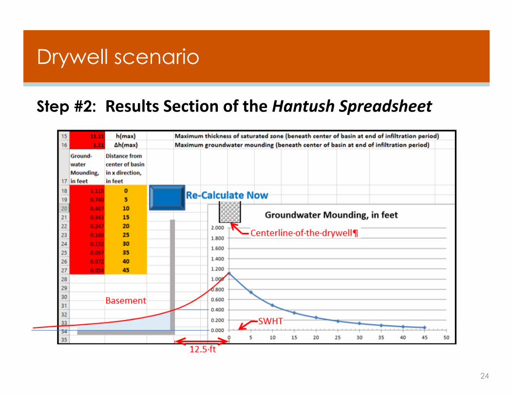
Drywell scenario
24
Step #2: Results Section of the Hantush Spreadsheet

Any Questions?
Bureau of Nonpoint Pollution ControlDivision of Water Quality401 East State StreetPO Box 420, Mail Code 401-2BTrenton, NJ 08625-420Tel: 609-633-7021www.njstormwater.org
Changi Wu Lisa [email protected] [email protected]
25