Embed Size (px)
Citation preview

Southern Nevada Water Authority Clark, Lincoln,
and White Pine Counties Groundwater Development Project
Conceptual Plan of Development
March 2011
Prepared By: Prepared For: Southern Nevada Water Authority U.S. Bureau of Land Management 100 City Parkway, Suite 700 Nevada State Office Las Vegas, Nevada 89106 Mailing Address: P.O. Box 99956 Las Vegas, Nevada 89193-9956
1340 Financial Boulevard Reno, Nevada 89502


GWD Project - Conceptual Plan of Development March 2011
ii
TABLE OF CONTENTS
TABLE OF CONTENTS ................................................................................................................ ii LIST OF FIGURES ....................................................................................................................... vi LIST OF TABLES ........................................................................................................................ vii LIST OF ACRONYMS ............................................................................................................... viii 1.0 PURPOSE OF PROJECT .................................................................................................... 1-1
1.1 PURPOSE AND NEED ............................................................................................... 1-1 1.2 PROPOSED PROJECT ............................................................................................... 1-1 1.3 WATER RIGHTS ........................................................................................................ 1-3 1.3.1 SNWA Water ....................................................................................................... 1-5 1.3.2 Lincoln County Water .......................................................................................... 1-7 1.3.3 Other SNWA Groundwater Applications Not Part of GWD Project .................. 1-8 1.4 GOVERNMENT AGENCIES INVOLVED ............................................................... 1-9
2.0 PROPOSED FACILITIES ................................................................................................... 2-1 2.1 PIPELINES .................................................................................................................. 2-1 2.1.1 Main Pipeline ....................................................................................................... 2-8 2.1.2 Lateral Pipelines................................................................................................. 2-12
Spring Valley Lateral ..................................................................................................... 2-12 Snake Valley Lateral ...................................................................................................... 2-12 Cave Valley Lateral ....................................................................................................... 2-13
2.1.3 Temporary Construction Areas .......................................................................... 2-13 Staging Areas ................................................................................................................. 2-13 Caliente Construction Support Area .............................................................................. 2-13 Temporary Plant Nursery Sites ...................................................................................... 2-14 Temporary Construction Camps .................................................................................... 2-14
2.1.4 Borrow Pits ........................................................................................................ 2-14 2.1.5 Pipeline Valves .................................................................................................. 2-15 2.2 PRESSURE REDUCING STATIONS ...................................................................... 2-16 2.3 PUMPING STATIONS ............................................................................................. 2-18 2.3.1 Spring Valley North Pumping Station ............................................................... 2-20 2.3.2 Spring Valley South Pumping Station ............................................................... 2-20 2.3.3 Snake Valley North Pumping Station ................................................................ 2-23 2.3.4 Snake Valley South Pumping Station ................................................................ 2-23 2.3.5 Lake Valley Pumping Station ............................................................................ 2-26 2.4 REGULATING TANKS ........................................................................................... 2-26 2.5 WATER TREATMENT FACILITY/BURIED STORAGE RESERVOIR .............. 2-29 2.6 POWER FACILITIES ............................................................................................... 2-31 2.6.1 Power Lines ....................................................................................................... 2-32 2.6.2 Electrical Substations ......................................................................................... 2-34
Primary Electrical Substations ....................................................................................... 2-34 Secondary Electrical Substations ................................................................................... 2-39
2.7 ACCESS ROADS ...................................................................................................... 2-39 2.8 COMMUNICATIONS FACILITIES ........................................................................ 2-42 2.9 FUTURE FACILITIES .............................................................................................. 2-42 2.9.1 SNWA Future Groundwater Production Wells ................................................. 2-42 2.9.2 Future Collector Pipelines .................................................................................. 2-44

GWD Project - Conceptual Plan of Development March 2011
iii
2.9.3 Future Pumping Stations .................................................................................... 2-45 2.9.4 Future Power Facilities ...................................................................................... 2-45 2.9.5 Future Access Roads .......................................................................................... 2-46 2.9.6 SNWA Future Facilities Summary .................................................................... 2-46 2.9.7 Lincoln County Future Facilities ....................................................................... 2-46
3.0 LAND REQUIREMENTS ................................................................................................... 3-1 3.1 PERMANENT AND TEMPORARY RIGHTS-OF-WAY ......................................... 3-1 3.2 FUTURE FACILITIES ................................................................................................ 3-1
4.0 CONSTRUCTION ............................................................................................................... 4-1 4.1 STANDARD CONSTRUCTION METHODS ............................................................ 4-1 4.1.1 Surveying and Staking ......................................................................................... 4-1 4.1.2 Clearing and Grading ........................................................................................... 4-1 4.1.3 Site Fencing ......................................................................................................... 4-1 4.1.4 Site Access ........................................................................................................... 4-2 4.1.5 Materials Storage ................................................................................................. 4-2 4.1.6 Sanitation, Water, and Power ............................................................................... 4-2 4.2 PIPELINE .................................................................................................................... 4-2 4.2.1 General Pipeline Construction Techniques .......................................................... 4-2
Trenching ......................................................................................................................... 4-3 Bedding ............................................................................................................................ 4-3 Pipe Laying and Welding ................................................................................................. 4-3 Upper Pipe Zone Backfilling ........................................................................................... 4-3 Trench Backfill ................................................................................................................ 4-3 Construction Water .......................................................................................................... 4-4 Hydrostatic Testing .......................................................................................................... 4-4
4.2.2 Special Pipeline Construction Techniques ........................................................... 4-5 Highway Road Crossings ................................................................................................. 4-5 Utility and Other Crossings ............................................................................................. 4-5 Steep Terrain .................................................................................................................... 4-5 Water Crossings ............................................................................................................... 4-5 Ephemeral Wash Crossings ............................................................................................. 4-6 Residential Areas ............................................................................................................. 4-6 Blasting ............................................................................................................................ 4-6 Tunneling ......................................................................................................................... 4-6
4.3 PUMPING AND PRESSURE REDUCING STATIONS ........................................... 4-6 4.4 REGULATING TANKS ............................................................................................. 4-7 4.5 WATER TREATMENT FACILITY/BURIED STORAGE RESERVOIR ................ 4-7 4.6 POWER FACILITIES ................................................................................................. 4-7
Power Lines ..................................................................................................................... 4-7 Substations ....................................................................................................................... 4-8
4.7 ACCESS ROADS ........................................................................................................ 4-8 4.8 COMMUNICATIONS FACILITIES .......................................................................... 4-9 4.9 CONSTRUCTION SCHEDULE, WORKFORCE, AND EQUIPMENT
ESTIMATES ............................................................................................................... 4-9 4.9.1 Construction Schedule ......................................................................................... 4-9 4.9.2 Workforce Estimates ............................................................................................ 4-9

GWD Project - Conceptual Plan of Development March 2011
iv
Construction Equipment ................................................................................................ 4-11 4.9.3 Future Facilities Construction ............................................................................ 4-15
5.0 OPERATION AND MAINTENANCE ............................................................................... 5-1 5.1 PIPELINES .................................................................................................................. 5-1 5.2 PUMPING STATIONS, REGULATING TANKS, AND PRESSURE REDUCING
STATIONS .................................................................................................................. 5-2 5.3 WATER TREATMENT FACILITY/BURIED STORAGE RESERVOIR ................ 5-2 5.4 POWER FACILITIES ................................................................................................. 5-3 5.5 ACCESS ROADS ........................................................................................................ 5-3 5.6 COMMUNICATIONS FACILITIES .......................................................................... 5-3 5.7 SECURITY .................................................................................................................. 5-3
6.0 TERMINATION .................................................................................................................. 6-1 APPENDIX A – APPLICANT ENVIRONMENTAL PROTECTION MEASURES ............... A-1 A. ROW Measures ...................................................................................................................... A-2
1. GENERAL CONSTRUCTION PRACTICES............................................................ A-2 Planning and Permitting ............................................................................................. A-2 Surveying .................................................................................................................... A-4 Fencing ....................................................................................................................... A-5 Clearing and Grading ................................................................................................. A-6 Access Roads .............................................................................................................. A-7 Construction ............................................................................................................... A-8 Stormwater and Erosion Control .............................................................................. A-10 Restoration ................................................................................................................ A-13 Noxious Weeds ......................................................................................................... A-15
2. GENERAL OPERATION PRACTICES .................................................................. A-17 Restoration Monitoring ............................................................................................ A-17
3. GEOLOGIC HAZARDS AND SOILS..................................................................... A-18 4. WATER RESOURCES ............................................................................................ A-19 5. BIOLOGICAL RESOURCES .................................................................................. A-19
Special Status Plants ................................................................................................. A-20 Desert Tortoise ......................................................................................................... A-21 Banded Gila Monster and Chuckwalla ..................................................................... A-24 Burrowing Owls and Kit Fox ................................................................................... A-25 Greater Sage-Grouse ................................................................................................ A-26 Pygmy Rabbit ........................................................................................................... A-27 Desert Valley Kangaroo Mouse ............................................................................... A-27 Migratory Birds (which include Raptors) ................................................................ A-28 Big Game and Wild Horses ...................................................................................... A-28 Game Fish ................................................................................................................. A-29
6. PALEONTOLOGICAL RESOURCES .................................................................... A-30 7. CULTURAL RESOURCES ..................................................................................... A-30 8. LAND USE AND RANGE MANAGEMENT ......................................................... A-31 9. NOISE ....................................................................................................................... A-32 10. AIR QUALITY ......................................................................................................... A-32 11. VISUAL RESOURCES ............................................................................................ A-34 12.. SOCIOECONOMICS ............................................................................................... A-34

GWD Project - Conceptual Plan of Development March 2011
v
B. Programmatic Measures – Future ROWs ............................................................................. A-35 1. PLANNING AND DESIGN ..................................................................................... A-35 2. GENERAL CONSTRUCTION PRACTICES.......................................................... A-35 3. GENERAL OPERATION PRACTICES .................................................................. A-36 4. WATER RESOURCES ............................................................................................ A-36 5. BIOLOGICAL RESOURCES .................................................................................. A-36
C. Regional Water-Related Effects ........................................................................................... A-37 1. MEASURES FROM SNWA AGREEMENTS ........................................................ A-38
Spring Valley Stipulation ......................................................................................... A-38 Delamar, Dry Lake, and Cave Valleys Stipulation .................................................. A-42 Spring Valley Hydrologic Monitoring and Mitigation Plan .................................... A-45 Conservation Agreement for Least Chub ................................................................. A-45 Conservation Agreement for Columbia Spotted Frog .............................................. A-46
2. ADAPTIVE MANAGEMENT PLAN AND MEASURES ..................................... A-46 Adaptive Management Framework .......................................................................... A-46 Environmental Goals and Objectives ....................................................................... A-48 Baseline Data Collection and Monitoring ................................................................ A-48 Identifying Environmental Indicators and Establishing Adaptive Management Thresholds .............................................................................................................. A-49 Monitoring Commitments ........................................................................................ A-50 Reporting Commitments .......................................................................................... A-50 Plan Implementation ................................................................................................. A-52 Adaptive Management Measures ............................................................................. A-55

GWD Project - Conceptual Plan of Development March 2011
vi
LIST OF FIGURES
Figure 1-1 Regional Location Map ............................................................................................. 1-2 Figure 1-2 Proposed Clark, Lincoln, and White Pine Counties Groundwater
Development Project .............................................................................................................. 1-4 Figure 1-3 Hydrographic Basins of the GWD Project ................................................................ 1-6 Figure 2-1 GWD Facilities – Steptoe, Spring, and Snake Valleys ............................................. 2-2 Figure 2-2 GWD Facilities – Steptoe, Spring, Snake, Hamlin, Lake, and Dry Lake Valleys ... 2-3 Figure 2-3 GWD Facilities – Spring, Lake, Cave, and Dry Lake Valleys ................................. 2-4 Figure 2-4 GWD Facilities – Dry Lake, Delamar, and Coyote Spring Valleys ......................... 2-5 Figure 2-5 GWD Facilities – Coyote Spring, Hidden, Garnet, and Las Vegas Valleys ............ 2-6 Figure 2-6 GWD Project Pipeline Diameters ............................................................................. 2-7 Figure 2-7 Preliminary GWD Project Ground Surface Profile ................................................... 2-9 Figure 2-8 Preliminary Pipeline and Power Line ROW Cross Section .................................... 2-12 Figure 2-9 Coyote Spring Valley Pressure Reducing Station ................................................... 2-17 Figure 2-10 Pumping Station Layout, Preliminary Floor Plan ................................................. 2-19 Figure 2-11 Pumping Station Layout, Preliminary Cross Section ............................................ 2-19 Figure 2-12 Preliminary Spring Valley North Pumping Station Site Plan ............................... 2-21 Figure 2-13 Preliminary Spring Valley South Pumping Station Site Plan ............................... 2-22 Figure 2-14 Preliminary Snake Valley North Pumping Station Site Plan ................................ 2-24 Figure 2-15 Preliminary Snake Valley South Pumping Station Site Plan ................................ 2-25 Figure 2-16 Preliminary Lake Valley Pumping Station Site Plan ............................................ 2-27 Figure 2-17 Preliminary 5-Acre Regulating Tank Site Plan ..................................................... 2-28 Figure 2-18 Preliminary Water Treatment Facility and Buried Storage Reservoir Site Plan ... 2-30 Figure 2-19 GWD Project Power Lines .................................................................................... 2-33 Figure 2-20 Preliminary 230 kV Power Pole with Underhang ................................................. 2-35 Figure 2-21 Preliminary 69 kV Power Pole .............................................................................. 2-36 Figure 2-22 Preliminary 25 kV Power Pole .............................................................................. 2-37 Figure 2-23 Preliminary Primary Electrical Substation Site Plan ............................................ 2-38 Figure 2-24 GWD Project Access Road Improvements ........................................................... 2-40 Figure 2-25 GWD Project Exploratory Areas .......................................................................... 2-43 Figure 4-1 GWD Project Potential Timeline ............................................................................ 4-15 Figure C-1 Adaptive Management Flow Diagram .................................................................. A-48 Figure C-2 Management Process for GWD Project ................................................................ A-53

GWD Project - Conceptual Plan of Development March 2011
vii
LIST OF TABLES
Table 1-1 Groundwater Rights and Applications Analyzed for Conveyance through the GWD Project .................................................................................................................................... 1-5
Table 1-2 Potentially Required Federal and State Permits and Reviews................................... 1-10 Table 2-1 GWD Project Pipelines ................................................................................................ 2-1 Table 2-2 Anticipated Operational Power Requirements .......................................................... 2-31 Table 2-3 GWD Project Power Lines ........................................................................................ 2-32 Table 2-4 Estimated Future SNWA Facilities ........................................................................... 2-47 Table 3-1 GWD Project Permanent and Temporary Right-Of-Way Estimates ........................... 3-2 Table 3-2 GWD Future Facilities Programmatic Estimates ........................................................ 3-4 Table 4-1 Preliminary Construction Schedule for Proposed Facilities ...................................... 4-10 Table 4-2 Estimated Peak Construction Workforce by Year ..................................................... 4-11 Table 4-3 Estimated Personnel and Equipment Required for Pipeline Construction ................ 4-12 Table 4-4 Estimated Personnel and Equipment Required for Power Line and Power Substation
Construction ......................................................................................................................... 4-13 Table 4-5 Estimated Personnel and Equipment Required for Facility Construction ................. 4-14 Table 5-1 Potential Water Treatment Chemicals ......................................................................... 5-3

GWD Project - Conceptual Plan of Development March 2011
viii
LIST OF ACRONYMS
afy acre-feet per year AMP Adaptive Management Plan BLM U.S. Department of Interior, Bureau of Land Management BMPs Best Management Practices BRT Biological Resources Team BWG Biological Working Group cfs cubic feet per second COM Plan Construction, Operation and Maintenance Plan DDC Stipulation Stipulation between SNWA and Department of the Interior
agencies on Delamar, Dry Lake, and Cave Valleys water rights DRI Desert Research Institute GWD Project Clark, Lincoln, and White Pine Counties Groundwater
Development Project kV kilovolt LCCRDA Lincoln County Conservation, Recreation, and Development Act
of 2004 MW megawatts NEPA National Environmental Policy Act NDEP Nevada Division of Environmental Protection NDOW Nevada Department of Wildlife Nevada State Engineer Nevada Division of Water Resources, Office of the State EngineerNRHP National Register of Historic Places NRS Nevada Revised Statutes ROW Right(s)-of-Way SNWA Southern Nevada Water Authority Spring Valley Stipulation
Stipulation between SNWA and Department of the Interior agencies on Spring Valley water rights
SR State Route SWPPP Storm Water Pollution Prevention Plan TRP Technical Review Panel US Hwy United States Highway USFWS United States Fish and Wildlife Service USGS United States Geological Survey WTF Water Treatment Facility Zone Interbasin Groundwater Monitoring Zone

This page intentionally left blank.

GWD Project - Conceptual Plan of Development March 2011
1-1
1.0 PURPOSE OF PROJECT
The Southern Nevada Water Authority (SNWA) currently holds groundwater rights and applications in Spring, Snake, Cave, Dry Lake, and Delamar valleys in Clark, Lincoln, and White Pine Counties, Nevada. SNWA has submitted a right-of-way (ROW) application to the Bureau of Land Management (BLM) to construct, operate, and maintain the Clark, Lincoln, and White Pine Counties Groundwater Development (GWD) Project. The ROW currently requested for the GWD Project includes the primary water and power conveyance facilities, including pipelines, pumping stations, flow regulation/storage facilities, a treatment and storage reservoir facility, pressure reducing stations, power lines, and electrical substations. ROWs for groundwater development facilities, including groundwater production wells, collector pipelines, and distribution power lines, will be submitted in the future when those facility sites are known.
The GWD Project facilities described in this plan of development would convey up to 217,655 acre-feet per year (afy) of water, including approximately 184,655 afy of SNWA’s water rights and applications and the remaining capacity provided for Lincoln County. Because the Nevada Division of Water Resources, Office of the State Engineer (Nevada State Engineer) has not yet issued a decision regarding SNWA’s pending groundwater applications in these valleys, the facilities described below are based upon the full quantity of SNWA’s pending applications. If a lesser quantity of water rights were permitted, facilities would be downsized accordingly
1.1 PURPOSE AND NEED
SNWA’s purpose in applying for ROW for the GWD Project is:
1. To develop and convey water rights that have been purchased by, permitted to, or may be permitted to SNWA in Spring, Snake, Cave, Dry Lake, and Delamar Valleys for use by SNWA’s member agencies in Clark County; and
2. To fulfill its contractual obligation to provide capacity for potential future use by the Lincoln County Water District, to transport as yet not identified water resources to its customers in Lincoln County.
SNWA’s need for the GWD Project is twofold. First, southern Nevada relies on the Colorado River to meet nearly all of the region’s water resource needs. Providing a source of supply other than the Colorado River is paramount and necessary to securing reliable water resources to meet existing and projected future demands. Periods of drought since 1999, predictions of reduced river flows due to climate change, and security concerns associated with reliance on a single source of supply have heightened the need for SNWA to reduce its reliance on the Colorado River and to develop additional water resources that will provide flexibility to respond to drought conditions. Second, an additional source of supply will allow SNWA to meet future projected water demand in Clark County.
1.2 PROPOSED PROJECT
The GWD Project consists of the construction and operation of groundwater production, conveyance, and treatment facilities, and power conveyance facilities. The regional location of the GWD Project is shown on Figure 1-1.
The SNWA has applied to the BLM for ROW to construct and operate the GWD Project. SNWA has currently requested ROW for the Project’s primary water and power conveyance facilities, including:

GWD Project - Conceptual Plan of Development March 2011
1-2
Figure 1-1 Regional Location Map

GWD Project - Conceptual Plan of Development March 2011
1-3
Main and Lateral Pipelines – approximately 306 miles of buried water pipelines, between 30 and 96 inches in diameter
Pumping Stations – 5 pumping station facilities Regulating Tanks – 6 regulating tanks, each approximately 3 to 10 million gallons
in capacity Pressure Reducing Stations – 3 facilities Buried Storage Reservoir – a 40 million gallon buried storage reservoir Water Treatment Facility (WTF) – up to 165 million gallon per day facility, and Power Facilities – approximately 323 miles of 230 kilovolt (kV), 69 kV, and 25 kV
overhead power lines, 2 primary electrical substations (230 to 69 kV), and 5 secondary substations (69 to 25 kV).
These facilities are generally displayed on Figure 1-2, and described in more detail in Chapter 2 of this document. These facilities are located predominantly on public lands managed by the BLM and are primarily within designated utility corridors.
Future facilities will be required to develop permitted groundwater rights and convey them to the primary conveyance facilities. Since the Nevada State Engineer has not yet issued a decision regarding SNWA’s pending groundwater applications, the final locations of the groundwater production wells and associated facilities to convey water into the primary system have not yet been determined. The wells will be located based on several factors, which include but are not limited to geology, hydrology, well interference studies, environmental issues, existing senior water rights, and proximity to main and lateral pipelines. Production well locations are also subject to approval by the Nevada State Engineer. Since the specific location of these facilities cannot currently be identified, SNWA has not yet requested ROW for them from the BLM. However, assumptions regarding the number of wells, length of collector pipelines, and other needed facilities have been made by SNWA so that BLM can conduct a programmatic-level environmental impact analysis of construction and operation of future facilities in addition to the site-specific analysis of proposed ROWs for primary facilities. SNWA anticipates that future facilities may include:
Groundwater Production wells – estimated between 144 to 174 wells Collector Pipelines – estimated between 177 to 434 miles, 10 to 30 inches in
diameter, and between 59 to 145 1-acre staging areas Pumping Stations – 2 facilities, and Power Facilities – estimated between 177 to 434 miles of 25kV overhead
distribution power lines (along collector pipeline alignments), 2 secondary substations, and hydroturbine energy generation (located at the pressure reducing sites).
1.3 WATER RIGHTS
The Proposed Action would develop and convey all water rights permitted by the Nevada State Engineer to SNWA for export from Spring, Snake, Cave, Dry Lake, and Delamar valleys. Table 1-1 summarizes the quantities of SNWA groundwater rights and applications by hydrographic basin, which are discussed below, as well as reasonably foreseeable water resources that may be conveyed on behalf of Lincoln County.

GWD Project - Conceptual Plan of Development March 2011
1-4
Figure 1-2 Proposed Clark, Lincoln, and White Pine Counties Groundwater Development Project

GWD Project - Conceptual Plan of Development March 2011
1-5
Table 1-1 Groundwater Rights and Applications Analyzed for Conveyance through the GWD Project
Hydrographic Basin
Existing Agricultural Groundwater
Rights (afy)
Groundwater Applications
(afy)
SNWA Water
Spring Valley 8,000 91,224
Snake Valley 50,679
Cave Valley a 11,584
Dry Lake Valley a 11,584
Delamar Valley a 11,584
Subtotal 8,000 176,655
Lincoln County Water
Lake Valley 11,300b
Additional Capacity – Source to be Determined
21,700
Subtotal 33,000
TOTAL 217,655 a 3,000 afy of water rights from these valleys would be transferred to Lincoln County in accordance with a 2003 cooperative agreement between SNWA and Lincoln County. b Privately owned water rights (allocated to Tuffy Ranch Properties, now owned by Coyote Spring Investments) are anticipated to be conveyed for Lincoln County.
1.3.1 SNWA Water
SNWA anticipates that a total water volume of up to 217,655 afy would be conveyed through the GWD Project. SNWA plans to develop up to 184,655 afy of its existing water rights and applications in Spring, Snake, Cave, Dry Lake, and Delamar valleys (Figure 1-3). Under the terms of a 2003 cooperative agreement, Lincoln County is entitled to 3,000 afy of water rights granted to SNWA in specified basins within Lincoln County. This 3,000 afy is included within the 184,655afy total of SNWA water rights and applications (Table 1-1), but is planned for conveyance through the GWD Project to Lincoln County, as described further in Chapter 1.3.2, below. In accordance with a 2006 cooperative agreement with Lincoln County, SNWA is reserving the remaining capacity in the GWD project for future use by Lincoln County. The water conveyed for Lincoln County may come from a variety of existing water rights and new appropriations which have not yet been determined, as described further in Chapter 1.3.2, below. A brief summary of the SNWA water rights that would be developed by SNWA and conveyed through the GWD Project is provided below.

GWD Project - Conceptual Plan of Development March 2011
1-6
Figure 1-3 Hydrographic Basins of the GWD Project
GWD Project - Conceptual Plan of Development March 2011
1-7
Spring Valley: SNWA holds applications for 91,224 afy of groundwater in Spring Valley. The Nevada State Engineer is anticipated to hold hearings on these applications in the Fall of 2011, with a water rights ruling issued in the Spring of 2012. The BLM and USFWS were parties to a Stipulated Agreement with SNWA signed in September 2006, to manage groundwater development without causing injury to Federal water rights and/or unreasonable adverse effects to Federal Resources. The Spring Valley Stipulated Agreement includes implementation of monitoring, management, and mitigation plans, as summarized in Appendix A.
SNWA has purchased private property and water rights in Spring Valley. As part of the GWD Project, SNWA plans to develop approximately 8,000 afy of its existing agricultural groundwater rights associated with these properties. Approval from the Nevada State Engineer to convert the type of use and allow export from the basin would be required prior to conveyance of these water rights through the GWD Project.
Cave, Dry Lake, and Delamar Valleys: SNWA holds applications for 34,752 afy of groundwater in these three valleys. The Nevada State Engineer is anticipated to hold hearings on these applications in the Fall of 2011, with a water rights ruling issued in the Spring of 2012. The BLM and USFWS were parties to a Stipulated Agreement with SNWA signed in January, 2008, to manage groundwater development without causing injury to Federal water rights and/or unreasonable adverse effects to Federal Resources and Special Status Species. The Stipulated Agreement includes implementation of monitoring, management, and mitigation plans, as described in Appendix A.
Snake Valley: SNWA holds applications for approximately 50,679 afy in Snake Valley. The Nevada State Engineer has not scheduled a hearing date for these applications. The Lincoln County Conservation, Recreation, and Development Act of 2004 (LCCRDA) requires that prior to “any transbasin diversion from ground-water basins located within both the State of Nevada and State of Utah, the State of Nevada and State of Utah shall reach an agreement regarding the division of water resources of those interstate ground-water flow system(s) from which water will be diverted and used by the project.” Pub. L. No. 108-424, § 301(e)(3), 118 Stat. 2403, 2412. A draft of this agreement was released August 13, 2009, but it has not yet been signed.
1.3.2 Lincoln County Water
Dry Lake and Delamar Valleys: Under the terms of a 2003 cooperative agreement between SNWA and Lincoln County, 3,000 afy of water rights that may be permitted to SNWA in these basins within Lincoln County would be transferred to Lincoln County. It is assumed that 1,500 afy of SNWA’s water rights in Dry Lake Valley and 1,500 afy of SNWA’s water rights in Delamar Valley would be transferred to Lincoln County. This 3,000 afy of groundwater is included in the 184,655 afy total for development by SNWA identified above. This water is expected to be conveyed through the GWD Project for use by Lincoln County.
Lake Valley: Tuffy Ranch Properties, LLC holds existing agricultural water rights in Lake Valley. The Nevada State Engineer issued Ruling 5918 on December 3, 2008 allowing export of up to 11,300 afy of existing agricultural water rights for municipal use in Coyote Spring Valley. The Nevada State Engineer determined that this quantity was the consumptively used portion of the existing water right, and there would be no increase in water use with export of the consumptive use portion from the basin.

GWD Project - Conceptual Plan of Development March 2011
1-8
Other Lincoln County rights and applications: Approximately 21,700 afy of additional capacity is planned for Lincoln County in the GWD Project for which no water source has yet been identified. Water sources may include potential transfer of existing agricultural rights or new appropriations in other groundwater basins in the area. Such transfers or new appropriations have not yet been requested, and the specific quantity and source basins cannot be reasonably forecast at this time. Additional federal action associated with ROW across federal lands would be required to develop and/or convey these future water supplies.
1.3.3 Other SNWA Groundwater Applications Not Part of GWD Project
SNWA holds other groundwater rights and applications in the region which are not planned for development through the GWD Project. These include water rights in Coyote Spring, Tikaboo, Three Lakes, Railroad, Hidden, and Garnet Valleys, which are more fully described in SNWA’s Resource Plan (2009).
In Coyote Spring Valley, SNWA holds pending applications for approximately 27,500 afy. In March 2002, the Nevada State Engineer issued Order 1169, requiring additional study on the effects of pumping existing permitted water rights in Coyote Spring Valley. SNWA has completed construction of facilities to conduct the required testing, which began in November 2010. The Nevada State Engineer determined in Order 1169 that he did not have sufficient information to make a decision on these water right applications based on currently available information, and it cannot be known whether results of the pumping test would be sufficient for the Nevada State Engineer to permit these applications. Thus, the potential future use of groundwater in Coyote Spring Valley pursuant to such applications is not considered reasonably foreseeable. Additionally, under the terms of a 2002 agreement if less than the full quantity of the applications were granted, Moapa Valley Water District would receive the first 3,750 afy with any remainder divided on a percentage basis. Depending upon the quantity that might be available to SNWA, SNWA may seek to transfer that water through its other Coyote Spring Valley facilities. Thus, SNWA’s pending Coyote Spring Valley applications are not identified for conveyance as part of the GWD Project.
In Tikaboo (North and South) and Three Lakes (North and South) Valleys, SNWA holds approximately 10,605 afy of water rights, permitted under Ruling 5465 and 5533. SNWA is working on options for the development of these groundwater permits through a separate project with delivery into the northwestern Las Vegas Valley (Three Lakes Valley Water Development Project). There are no plans to convey these water rights through the GWD Project.
SNWA holds groundwater applications for approximately 110,000 afy in Railroad Valley (North and South), which were originally filed in 1989. SNWA has not requested hearing on these applications, and has not identified a project for development of these applications. Railroad Valley is located three basins west from the main pipeline of the GWD Project, and there are no plans for conveyance of this water through the GWD Project.
In Hidden and Garnet Valleys, a combined total of 2,200 afy of water rights were permitted to the Las Vegas Valley Water District. The majority of these rights have been leased to dry-cooled power plants located in Garnet Valley. None of these rights are planned for conveyance through the GWD Project.

GWD Project - Conceptual Plan of Development March 2011
1-9
1.4 GOVERNMENT AGENCIES INVOLVED
Federal and state permits potentially required to construct and operate the GWD Project facilities described in this plan of development are listed in Table 1-2. Additional permits may be also required for future GWD Project facilities, such as a Federal Energy Regulatory Commission license to construct and operate future hydroturbines, which will be identified when those facilities are planned.

GWD Project - Conceptual Plan of Development March 2011
1-10
Table 1-2 Potentially Required Federal and State Permits and Reviews
Agency Permit/Approval
Federal
Bureau of Land Management
National Environmental Policy Act compliance National Historic Preservation Act Section 106 complianceIndian Trust and Native American Graves Protection and Repatriation Act coordination
Environmental Protection Agency National Environmental Policy Act reviews
Federal Highway Administration Permit to cross Federal Aid highway
U.S. Army Corps of Engineers Clean Water Act Section 404 permit
U.S. Fish and Wildlife Service Endangered Species Act Section 7 consultation Migratory Bird Treaty Act consultation Bald and Golden Eagle Protection Act consultation
State
Nevada Department of Cultural Affairs, State Historic Preservation Office
National Historic Preservation Act Section 106 review and concurrence
Nevada Division of Environmental Protection, Bureau of Water Pollution Control
Clean Water Act Section 401 water quality certification General storm water permit for construction (National
Pollutant Discharge Elimination System permit) Temporary discharge permit Temporary groundwater discharge permit Working in waterways permit Underground injection control permit
Nevada Division of Environmental Protection, Bureau of Safe Drinking Water
Letter of approval to construct
Nevada Department of Transportation Encroachment into State Highway rights-of-way Rights-of-way occupancy permits
Nevada Department of Wildlife Special Purpose Permit (handling for desert tortoise, Gila
monster, and other sensitive species)
Nevada Division of Forestry Collection permit for state-listed plants
Nevada Division of State Lands Construction easements across state lands
Nevada Division of Water Resources
Water right permits Well driller’s permit Dam safety permit Recharge, storage, and recovery of underground water
permit

GWD Project - Conceptual Plan of Development March 2011
2-1
2.0 PROPOSED FACILITIES
The proposed GWD Project primary water and power conveyance facilities, including pipelines, power lines, and ancillary facilities, are described below and generally displayed on Figures 2-1 through 2-5. Specific facility locations are displayed on the Topographic Maps accompanying this document (locations referenced in the text below by Sheet number refer to the Topographic Maps).
2.1 PIPELINES
The final sizes of the GWD Project main and lateral pipelines will be determined during facility design based on detailed topography, friction coefficients appropriate to the selected pipe materials, the need for operational flexibility, and the final locations of groundwater production well fields. However, final pipe sizes are not anticipated to require additional ROW. The main pipeline may be between 66 and 96 inches in diameter, extending between southern Spring Valley and the Las Vegas Valley. Lateral pipelines may be between 30 and 60 inches in diameter and would extend into northern Spring, Snake, and Cave Valleys. Figure 2-6 displays the anticipated general areas of different pipeline diameters. Table 2-1 lists the specific pipeline distances by valley and anticipated pipe diameter.
Table 2-1 GWD Project Pipelines
Pipeline Valley Pipe Diameter Pipe Length*
(inches in diameter)
(miles)
Main Pipeline
Spring 78 17
Lake 78 21
Dry Lake 84 66
Delamar 90 23
Pahranagat 66-78 7
Coyote Spring 96 41
Hidden 96 12
Garnet 90-96 7
Las Vegas 90 9
Spring Lateral Spring 60 38
Snake Lateral
Snake 54 24
Hamlin 54 10
Spring 54 9
Cave Lateral Cave 30 19
Dry Lake 30 3
TOTAL 306 * Pipe lengths are rounded to the nearest mile.

GWD Project - Conceptual Plan of Development March 2011
2-2
Figure 2-1 GWD Facilities – Steptoe, Spring, and Snake Valleys

GWD Project - Conceptual Plan of Development March 2011
2-3
Figure 2-2 GWD Facilities – Steptoe, Spring, Snake, Hamlin, Lake, and Dry Lake Valleys

GWD Project - Conceptual Plan of Development March 2011
2-4
Figure 2-3 GWD Facilities – Spring, Lake, Cave, and Dry Lake Valleys

GWD Project - Conceptual Plan of Development March 2011
2-5
Figure 2-4 GWD Facilities – Dry Lake, Delamar, and Coyote Spring Valleys

GWD Project - Conceptual Plan of Development March 2011
2-6
Figure 2-5 GWD Facilities – Coyote Spring, Hidden, Garnet, and Las Vegas Valleys

GWD Project - Conceptual Plan of Development March 2011
2-7
Figure 2-6 GWD Project Pipeline Diameters

GWD Project - Conceptual Plan of Development March 2011
2-8
The identified preliminary pipeline diameters balance initial facility cost and long-term life cycle. Smaller diameter pipelines may be initially less expensive to construct, but can impose higher operating costs because more hydraulic energy is lost when water flows through a smaller pipeline compared to a larger pipeline. The preliminary pipe diameters were determined utilizing standard engineering formulas and applying SNWA’s standard design criteria including:
250 pounds per square inch maximum operating pressure 20 pounds per square inch minimum operating pressure Friction coefficients of 135-140 (Hazen-Williams) – a measurement of the
resistance to the flow of water; the less friction, the less energy it takes to convey water through the pipeline, and
6 feet minimum depth of earth cover over the pipeline.
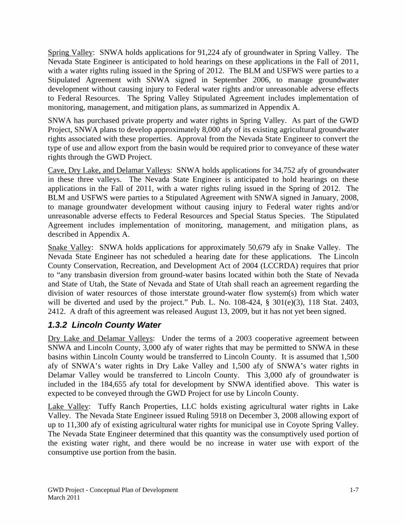
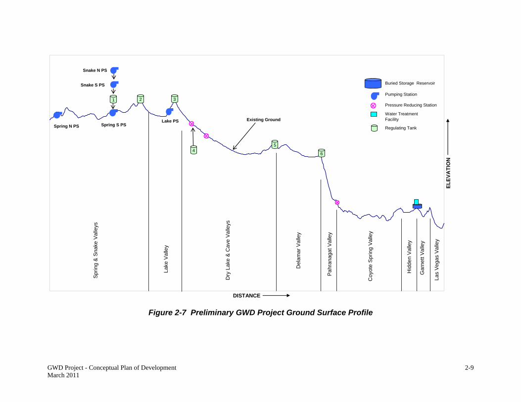
A ground surface profile of the GWD Project is displayed in Figure 2-7. The estimated maximum elevation is approximately 6,500 feet at Muleshoe Summit in northern Dry Lake Valley. The minimum elevation is approximately 2,100 feet near the pipeline terminus in the Las Vegas Valley.
All pipelines would be completely buried, with the exception of structures for air/vacuum valves, and isolation and drain valves, which may be partially buried or have vents extending above ground (Chapter 2.1.5). There would be no permanent security fencing or other permanent access restrictions on the pipeline ROWs. Temporary security and environmental exclusion fencing would be used as needed on pipeline segments during construction (see Appendix A).
2.1.1 Main Pipeline
The main pipeline would begin in southern Spring Valley, on the east side of the Fortification Range, just south of the Lincoln and White Pine County border (Sheet 1). This is also the location of the Spring Valley South Pumping Station (Chapter 2.3). The pipeline is estimated to be up to 78 inches in diameter. It would extend south towards the town of Atlanta, following an existing unpaved road (Indian Springs Road). Prior to reaching Atlanta, the alignment turns to the west (Sheet 5). It continues to follow an existing road and then crosses Horse Corral Pass into Lake Valley (Sheet 5).
In Lake Valley, the pipeline would follow existing dirt roads to the southwest, around the southern end of the Fortification Range, and then turn westward along existing roads across the valley floor. The main pipeline would cross U.S. Highway (US Hwy) 93 in the vicinity of Dutch John Well (Sheet 8), enter Muleshoe Pass, and turn south towards Dry Lake Valley (Sheets 8-10).
The main pipeline route extends south along existing roads through the center of Dry Lake Valley. With the addition of water in northern Dry Lake Valley, the main pipeline may increase to up to 84 inches in diameter. It would pass through the central part of the valley and around the eastern side of the dry lakebed until reaching US Hwy 93 (Sheet 25). By the southern portion of Dry Lake Valley, the pipeline may increase to up to 90 inches in diameter. The pipeline would extend west along the northern side of US Hwy 93 for approximately 3 miles before turning south along an existing dirt road near the old Delamar Landing Field. The main pipeline route continues south along the existing road before entering Delamar Valley (Sheets 25-26).
GWD Project - Conceptual Plan of Development March 2011
2-9
DISTANCE
EL
EV
AT
ION
Spring S PS
Pumping Station
Water Treatment Facility
Pressure Reducing Station
Buried Storage Reservoir
Existing Ground
2
Regulating Tank
Snake S PS
4
1
Spring N PS
5
6
3
Las
Veg
as V
alle
y
Gar
nett
Val
ley
Hid
den
Val
ley
Coy
ote
Spr
ing
Val
ley
Pah
rana
gat V
alle
y
Del
amar
Val
ley
Dry
Lak
e &
Cav
e V
alle
ys
Lake
Val
ley
Spr
ing
& S
nake
Val
leys
Snake N PS
Lake PS
Figure 2-7 Preliminary GWD Project Ground Surface Profile

This page intentionally left blank.
GWD Project - Conceptual Plan of Development March 2011
2-11
The main pipeline would extend south along existing dirt roads through the central part of Delamar Valley. It would follow the eastern side of the dry lakebed before entering Pahranagat Canyon in the southern end of Pahranagat Valley (Sheets 26-32).
The main pipeline would cross through the southern end of Pahranagat Valley, following an existing road and fiber optic cable alignment, before reaching US Hwy 93 and entering northern Coyote Spring Valley (Sheets 32-33).
The main pipeline would follow US Hwy 93 through Coyote Spring Valley where it is estimated to be 96 inches in diameter (Sheets 33-44). The alignment is on the west side of the highway through most of Coyote Spring Valley, but crosses to the east side near the northern end of the valley (Sheets 34-37). There are two rock outcrops near the Coyote Spring/Hidden Valley border that will be avoided by crossing to the east side of US Hwy 93 (Sheets 43-44). The pipeline would continue to follow US Hwy 93 southward into Hidden Valley (Sheet 45).
The pipeline would follow US Hwy 93 through Hidden Valley and enter Garnet Valley where US Hwy 93 turns east to Interstate 15 (Sheets 45-47). The pipeline would connect into the Water Treatment Facility and Buried Storage Reservoir approximately 0.5 mile south of US Hwy 93 (Chapter 2.5, Sheet 47). The pipeline would continue south from this location within an existing utility corridor to enter the Las Vegas Valley (Sheets 47-49).
Southward from the Las Vegas Valley-Garnet Valley border, the alignment extends in the vicinity of the existing Kern River gas line and NV Energy, Inc. power line alignments. In the Apex area, the pipeline would be constructed in an underground tunnel east of the Nellis Air Force Base Small Arms Range, on BLM and private land. Trenching of the pipeline would resume when it leaves the tunnel until it terminates into an existing SNWA water line on Lamb Boulevard and Grand Teton Drive (Sheets 49-50).
Permanent ROW of up to 100 feet in width and temporary construction ROW of an additional 100 feet are required for the main pipeline. In areas of level terrain and stable soil conditions, the amount of disturbance within the temporary ROW may be reduced, however any potential reductions would not be known until after design has been completed. Figure 2-8 shows a preliminary ROW cross section, which is representative of contiguous pipeline and power line ROW for most of the GWD Project, including typical maximum measurements. The 100-foot permanent ROW for the main pipeline accommodates a 50 to 70 foot wide trench, with a side slope from 0.75:1 to 2:1 (i.e., a slope that rises 1 foot vertically for every 0.75 to 2 feet horizontally) and a depth of at least 6 feet from the ground surface to the top of the pipe. This cross section may vary depending on soil conditions, surface topography, and pipe diameter. The remaining permanent and temporary ROW are used for excavated material storage, pipe storage before installation, movement of heavy equipment, and safe personnel work space.
The permanent ROW requested for the main pipeline totals approximately 2,455 acres. The main pipeline route crosses lands managed by the BLM (2,399 acres) and the State of Nevada (13 acres), and private land (43 acres). In Coyote Spring Valley and the vicinity of Apex, approximately 8 acres of temporary construction ROW are associated with the nursery areas and pipeline staging areas. Therefore, the area requested for temporary ROW totals approximately 2,463 acres, 8 acres greater than the permanent ROW. The main pipeline temporary ROW crosses lands managed by the BLM (2,416 acres) and the State of Nevada (13 acres), and private land (34 acres). A detailed list of ROW requirements is shown in Table 3-1.

GWD Project - Conceptual Plan of Development March 2011
2-12
Figure 2-8 Preliminary Pipeline and Power Line ROW Cross Section
2.1.2 Lateral Pipelines
Three primary lateral pipelines would branch off the main pipeline and extend into northern Spring Valley, Snake Valley, and Cave Valley. They are described in more detail below. Permanent and temporary ROW widths for the laterals are 100 feet each. The ROW cross section is the same as described for the main pipeline and shown on Figure 2-8. Because the pipe diameter of the lateral is not substantially smaller than the diameter of the main pipeline, and the work space needs for equipment, soil stockpiles, and material remain fairly constant, the width of temporary ROW required for construction of a lateral remains at 100 feet. As described for the main pipeline, the amount of disturbance within the temporary ROW may be reduced in areas of level terrain and stable soil conditions, however any potential reductions would not be known until after design has been completed.
Spring Valley Lateral
The Spring Valley Lateral would extend north from the Spring Valley South Pumping Station into central Spring Valley. This lateral may be up to 60 inches in diameter. From the Spring Valley South Pumping Station (Sheet 1), the lateral would extend northward to US Hwy 93 on the north side of an existing dirt road (Sheet 51). The lateral would continue north on the east side of US Hwy 93 to the junction of US Hwys 93, 6, and 50 (Sheets 52-56). At this location, the Spring Valley Lateral would cross to the north side of US Hwys 6 and 50, then turn northward along the west side of State Route (SR) 893. The lateral would continue northward on the west side of SR 893, terminating approximately 1 mile north of Bastian Creek (Sheets 56-59).
The Spring Valley Lateral would be located on land managed by the BLM. The permanent ROW needed is approximately 38 miles long and 100 feet wide, or 462 acres. The temporary ROW would be the same.
Snake Valley Lateral
The Snake Valley Lateral may be up to 54 inches in diameter, and would extend into Snake Valley from the Spring Valley South Pumping Station (Sheet 1). The lateral would extend east from the Spring Valley South Pumping Station on existing dirt roads around the southern end of the Snake Range (Sheets 60-61). The lateral pipeline would continue to follow existing dirt roads past “The Troughs,” turn northeast and pass Big Spring Wash, where it would enter Snake Valley (Sheets 62-63). It would head north on existing dirt roads through the Nevada side of

GWD Project - Conceptual Plan of Development March 2011
2-13
Snake Valley, passing several private properties. Near Chokecherry Creek, the lateral would turn northeast on existing dirt roads and extend cross-country (Sheets 65-66). The alignment would remain in Nevada, and cross the lower portions of Big Wash and Snake Creek before reaching Highway 487 (Sheets 67-69). Although this ROW would be on existing roads most of the way, there are stretches totaling approximately 3.5 miles near the terminus at Highway 487 where there are no existing roads. The lateral would follow the highway before terminating south of the town of Baker (Sheet 69).
The Snake Valley lateral would be on land managed by the BLM. The permanent ROW needed is approximately 43 miles long and 100 feet wide, or 519 acres. The temporary ROW would be the same.
Cave Valley Lateral
The Cave Valley Lateral may be up to 30 inches in diameter, and would connect Cave Valley into the main pipeline. The lateral would have both north and south segments located on the existing Cave Valley Road, on the eastern side of Cave Valley. The Cave Valley Lateral would begin at the main line in northern Dry Lake Valley at Sidehill Pass (Sheet 11), and extend over Sidehill Pass to Cave Valley Road on the valley floor, a distance of approximately 5 miles (Sheet 71). From the intersection of Sidehill Pass Road and Cave Valley Road, the north segment of the lateral would extend approximately 11 miles on Cave Valley Road, and terminate approximately 5 miles south of Patterson Pass Road (Sheets 71-74). The south segment would extend approximately 7 miles to the vicinity of the Silver King Mine (Sheets 70-71).
The Cave Valley Lateral would be located on land managed by the BLM. The permanent ROW requested is approximately 22 miles long and 100 feet wide, or 272 acres. The temporary ROW would be the same.
2.1.3 Temporary Construction Areas
Staging Areas
Temporary construction staging areas are required for pipeline construction. These staging areas would be used for equipment and materials storage, construction office trailers, fuel storage, plant storage, equipment maintenance, and temporary stockpiling. Not every staging area would include all of these uses. Temporary security fencing may be used to enclose staging areas during project construction; this fencing would be removed at the completion of construction activities.
Staging areas are planned to be placed approximately 3 miles apart immediately adjacent to the pipeline ROW. In total, ninety-seven 3-acre staging areas are proposed next to the main and lateral pipelines. The locations of the staging areas are displayed on the attached topographic maps. All of the ROW for the staging areas would be temporary, which total 291 acres.
Caliente Construction Support Area
A potential site for construction support has been identified on private land in the Caliente area (Sheet 83). This site may be used during construction for pipe and equipment storage, temporary construction management offices, and other construction support activities. The private lands encompass approximately 121 acres, about half of which may be used for pipe storage. Pipe is anticipated to be fabricated at one or more existing manufacturing plants in the western U.S. and may be delivered to the construction support area for storage or directly to the pipeline ROW for

GWD Project - Conceptual Plan of Development March 2011
2-14
installation. Drainage along the northeast portion of the site and the floodplain of Meadow Valley Wash near the southeast border would not be disturbed by the temporary construction use.
Temporary Plant Nursery Sites
Temporary plant nursery sites are required for storing cacti, yuccas, and other plants that would be salvaged within the ROW for subsequent use in restoration activities. While some of the pipeline staging areas may also be used for plant storage, an additional 19 nursery sites have been sited along the pipeline ROW. The nurseries would occupy approximately 249 acres of temporary ROW. The size and location of the individual nursery sites vary depending on the density of vegetation anticipated for salvage in adjacent ROW. Each nursery site would be secured from theft or vandalism by installing temporary security fencing around the entire perimeter with gates for ingress and egress. The nursery sites in the Mojave Desert would also have tortoise exclusion fencing installed onto the security fencing.
Temporary Construction Camps
Temporary construction worker camps may be needed, depending upon the availability of lodging and support services available in nearby communities. The size, number, location, and amenities required cannot be determined until facilities have been designed and a detailed construction schedule determined. SNWA would coordinate with local communities in advance of construction, to encourage local development of necessary services.
If temporary construction camps are still determined to be needed, it is anticipated that they would be located on private lands in and near communities in the vicinity of the project, such as Alamo, Caliente, Pioche, Ely, and Baker. No federal ROWs are anticipated. Temporary camps may require permits for sanitary facilities, water, and other requirements. Construction personnel would be transported daily from the camps to the construction sites by vans or buses to minimize traffic.
2.1.4 Borrow Pits
Soil materials used for bedding and backfilling of the pipelines must meet specified engineering standards. Preliminary geotechnical borings were conducted along the main pipeline alignment in 2006, and indicated that existing soils in some areas may be unsuitable for bedding and backfill. Therefore, imported soil material is anticipated to be required. Some of the needed material could be supplied from surplus trench excavation. However, it is anticipated that borrow pits would be required to supply backfill for pipeline construction in some areas.
A total of eight sites potentially suitable for borrow pits have been identified:
Borrow Pit 1 in northern Spring Valley, where the Spring Lateral pipeline crosses US Hwys 6 and 50 (Sheet 56)
Borrow Pit 2 in Snake Valley, near Big Spring Wash (Sheet 63) Borrow Pits 3 and 4 in Lake Valley, where the main pipeline crosses US Hwy 93
(Sheet 8) Borrow Pits 5 and 6 in southern Cave Valley, approximately 3 miles south of
Sidehill Pass (Sheet 71), and Borrow Pits 7 and 8 in Dry Lake Valley, approximately 20 miles north of US Hwy
93 in the vicinity of the Fissures (Sheet 20).

GWD Project - Conceptual Plan of Development March 2011
2-15
Each borrow pit site is approximately 7 acres in size. Approximately half of the space would be used for the borrow pit, and the other half for processing equipment, stockpiles for processed material, and transport equipment. Each borrow pit may be excavated up to a depth of approximately 15 feet. Approximately 18 million cubic feet of borrow material is anticipated to be removed from all eight pits combined if they were excavated to maximum proposed capacity. The borrow pits would be re-filled with excess soils from the excavated pipe trenches that are unsuitable for pipeline backfill. It is not anticipated that additional soil disposal sites would be needed.
All of the borrow pits would be on land managed by the BLM. Each borrow pit site is approximately 552 feet long and 552 feet wide, or 7 acres. The temporary ROW requested for all eight borrow pits is approximately 56 acres.
2.1.5 Pipeline Valves
Air release, air/vacuum, drain, and isolation valves would be installed along the pipeline for system operation. The locations of these valves are dependent upon elevation, and the final sites would be determined during pipeline design after detailed topographic surveys have been completed.
Air release valves are used to release air within the pipeline, and would be located at or near all high points, grade breaks on steep slopes, and long downward sloping pipe segments. Air/vacuum valves both discharge air and allow air to enter the pipeline, and would be located generally at significant high points and near isolation valves. The air vent connects directly to the top of the water pipeline through check valves so air can pass aboveground. Air release and air vacuum valves are housed in either below-ground or partially buried structures, with a 12- to 24-inch gooseneck pipe extending approximately 2 to 3 feet above ground level. Locations would be determined during design, but several hundred air release and air/vacuum valves are anticipated along the main and lateral pipelines.
Drain valves would be located at the lowest pipeline elevations in any pipe segment. Drain valves are used if necessary to drain the pipeline. This may be done during the hydrostatic testing of the pipeline conducted at the completion of construction, and if needed to allow emergency repairs. Drain valve piping is connected to the bottom of the pipeline at a low point and extends to a discharge location which is generally a dry wash channel. The water is passed through an energy dissipater if required before being discharged, and the wash channel is typically lined with rip rap at and immediately below the discharge location to avoid the potential for erosion. A detailed hydrologic analysis would be conducted during facility design for each discharge point to provide sufficient erosion control and prevent scouring, however, it is currently anticipated that discharge flow rates and volumes would not be allowed to exceed the two to five year storm event for the individual drainages. Although locations cannot yet be determined, drain valves may be placed approximately 1 to 10 miles apart.
Isolation valves are belowground or partially buried appurtenances that are remotely monitored and controlled. Rapid closing of valves, even in an emergency, can result in excessive and dangerous pressures within the pipeline. The closing time for each valve would be identified during project design based upon a detailed hydraulic analysis, but is estimated to be approximately 15-25 minutes. Isolation valves are built in-line with the water pipeline and stop the flow of water through the pipeline when in the closed position. Isolation valves require an air/vacuum valve that equalizes the pressure inside the pipeline and avoids pipe collapse if the

GWD Project - Conceptual Plan of Development March 2011
2-16
pipe is drained. They would also be constructed in conjunction with a drain valve in order to drain the pipeline for maintenance. Although locations cannot be determined until the pipeline design is complete, the isolation valves would be spaced to minimize water loss in case of emergency breaks. For the purposes of analysis, it is anticipated that pipeline isolation valves would be located approximately 10 miles apart.
Valves are typically housed inside an underground, square or rectangular vault that is large enough for a person to access. The vault is built surrounding the water pipeline. The top of the vault contains a large, removable access hatch and one or more, smaller access ways large enough to accommodate a person. The vault vent extends a few feet aboveground.
All valves are located within the permanent ROW requested for the pipelines, and additional permanent or temporary ROW is not needed.
2.2 PRESSURE REDUCING STATIONS
Three pressure reducing stations are needed along the pipeline alignment to maintain internal pipeline pressures at manageable levels. Two are located in Dry Lake Valley (Sheets 11 and 14), and the other in northern Coyote Spring Valley (Sheet 33). The three pressure reducing stations are shown on the project ground surface profile on Figure 2-7. The locations for these facilities were determined based on anticipated maximum water pressure and pipe pressure rating.
The pressure reducing stations are needed on the main pipeline where water pressure exceeds the pipe pressure rating. These facilities would maintain water pressure within the limits for which the pipelines and facilities are designed. This would avoid damage to the pipelines and appurtenant facilities, and potential pipeline rupture caused by water pressure greater than the design limit.
The pressure reducing facilities would be located in partially buried vaults. The facilities at each site would include isolation valves, pressure reducing valves, and an overflow basin. Additionally, because of the type of valves (sleeve valves) required to dissipate the high pressures, downstream storage tanks are also required for each site. These tanks provide a discharge point for the valves, and are also part of the overall system hydraulics providing regulation for valve closing/opening and surge protection. The Coyote Spring Valley site would also contain a secondary substation, a maintenance building, and three water storage tanks (Figure 2-9).
The permanent ROW for the Dry Lake Valley North and South Pressure Reducing Stations is approximately 295 feet long and 295 feet wide per facility, or 2 acres each. The length of the permanent ROW for the Coyote Spring Valley Pressure Reducing Station is approximately 1,266 feet long; the width varies and averages approximately 242 feet wide. The site is approximately 7 acres. The temporary ROW required for construction of the Dry Lake Valley North and South Pressure Reducing Stations is approximately 466 long by 466 feet wide per facility, or 5 acres each. The temporary ROW required for construction of the Coyote Spring Valley Pressure Reducing Station is approximately 1,266 feet long; the width of the temporary ROW also varies and averages approximately 206 feet wide. The temporary ROW is approximately 6 acres.

GWD Project - Conceptual Plan of Development March 2011
2-17
Figure 2-9 Coyote Spring Valley Pressure Reducing Station

GWD Project - Conceptual Plan of Development March 2011
2-18
2.3 PUMPING STATIONS
Five pumping stations are required to move water for the GWD Project. All of the pumping stations are located adjacent to a main or lateral pipeline. The location and size of each pumping station is described in more detail below. Facilities common to each pumping station include:
Pumps and motors Forebay (surge facility or water storage tank for stabilization of system hydraulics) Surge control system Instrumentation and control systems Electrical facilities including switchgear, transformers, motor control centers, local
control panels, lighting, and standby diesel generator with fuel storage tank Mechanical systems including heating, ventilation, air conditioning, plumbing,
hoists, cranes, and compressors Chemical addition facilities, where needed Break room and restroom, with associated septic tank and leach field, and Site fencing and security provisions.
Figures 2-10 and 2-11 respectively show a preliminary floor plan and cross section of a pumping station using horizontal split-case pumps. Pumping stations are contained in a concrete or concrete block building. The approximate heights of the pumping station buildings vary between 24 and 40 feet above grade, depending on conditions such as terrain, pump size, and other environmental and equipment requirements.
A facility electrical substation is included at each pumping station site to reduce the power voltage to the operational requirements. The sites may be partially paved, with remaining areas covered with crushed gravel, and have security fencing with a locked gate enclosing each site.
A diesel-powered standby generator would be included at each pumping station site. The generator needs to be large enough to operate one of the pumps in each pumping station, in order to maintain pressures in the pipeline in the event of a power outage. As a conservative scenario, a catastrophic power loss might take up to 72 hours to repair. Therefore, the diesel generators would be designed to be capable of operating up to 72 hours continuously.
A diesel storage tank for fuel storage to operate the generator would be located at each site. Each tank is anticipated to be up to 2,400 gallons in capacity, with a steel inner tank, outer reinforced concrete shell, and Styrofoam insulation in between. These tanks would meet current regulatory requirements for containment and be equipped with monitoring equipment for leak detection. The generator at each pumping station would be operated approximately once each month for 1 to 2 hours to ensure that it is in good working order. Diesel fuel would be hauled by tanker truck to the pumping station sites as needed to fill the fuel storage tanks, anticipated to be approximately once each year.

GWD Project - Conceptual Plan of Development March 2011
2-19
Figure 2-10 Pumping Station Layout, Preliminary Floor Plan
Figure 2-11 Pumping Station Layout, Preliminary Cross Section

GWD Project - Conceptual Plan of Development March 2011
2-20
2.3.1 Spring Valley North Pumping Station
The Spring Valley North Pumping Station would be located along the Spring Valley Lateral pipeline alignment adjacent to SR 893, approximately 5 miles north of US Highways 6 and 50 (Sheet 58).
As shown on Figure 2-12, the site includes the pumping station, a surge facility, a generator building to house the standby electrical generator, and a small electrical substation to serve the pumping station. The pumping station would lift the water in the Spring Valley Lateral over a high point located near the junction of Highways 93, 50, and 6, and into southern Spring Valley where the lateral ties into the main pipeline at the Spring Valley South Pumping Station. Although the number of pumps required at this pumping station cannot be determined until final facility design, for the purposes of analysis, 6 pumps at 500 horsepower each are anticipated. Adjacent to the north side of the pumping station site is the Spring Valley Secondary Electrical Substation, which is not part of the pumping station. The secondary electrical substation is described in Chapter 2.6.2.
The permanent ROW requested for the Spring Valley North Pumping Station is approximately 466 feet long and 466 feet wide, or 5 acres. Additionally, a temporary ROW (Facility Staging Area) 466 feet long and 466 feet wide, or 5 acres, is required for construction.
2.3.2 Spring Valley South Pumping Station
The Spring Valley South Pumping Station would be located on the west side of Indian Springs Road approximately 2 miles south of Indian Springs Knolls (Sheet 1). The pumping station would collect water from the Spring and Snake Laterals along with other groundwater in southern Spring Valley and move it over Horse Corral Pass. As shown in Figure 2-13, this site is larger than the other pumping station sites because, in addition to the pumping station, it accommodates a primary electrical substation (see Chapter 2.6.2, below), a warehouse, and an outdoor storage yard. Space is also allotted for possible water treatment, such as arsenic and chlorination, if determined to be needed.
The pumping station site includes a pumping station, surge facility, a generator building to house the standby electrical generator, a small facility electrical substation to serve the pumping station, an operations building, a warehouse, and an outdoor storage yard. Although the number of pumps required at this pumping station cannot be determined until final facility design, for the purposes of analysis, 10 pumps at 1,250 horsepower each are anticipated.
The primary electrical substation is needed to reduce power levels down to operational levels. It is described in detail in Chapter 2.6.2. The warehouse and outdoor storage yard would be used for storage of parts and equipment, and facility and equipment maintenance activities. If biological organisms, such as protozoans or bacteria, are present in the groundwater, chemicals for biological control, such as sodium hypochlorite, may be stored and used at this facility.
The permanent ROW requested for the Spring Valley South Pumping Station is approximately 1,615 feet long and 1,615 feet wide, or 60 acres. A temporary ROW is not required for this site since the space allotted for the outdoor storage yard could be used during facility construction.

GWD Project - Conceptual Plan of Development March 2011
2-21
Figure 2-12 Preliminary Spring Valley North Pumping Station Site Plan

GWD Project - Conceptual Plan of Development March 2011
2-22
Figure 2-13 Preliminary Spring Valley South Pumping Station Site Plan

GWD Project - Conceptual Plan of Development March 2011
2-23
2.3.3 Snake Valley North Pumping Station
The Snake Valley North Pumping Station would be located along the Snake Valley Lateral pipeline alignment, approximately 5 miles southeast of the town of Baker (Sheet 68).
As shown on Figure 2-14, the site includes the pumping station, a surge facility, a generator building to house the standby electrical generator, and a small electrical substation to serve the pumping station. The pumping station would work in tandem with the Snake Valley South Pumping Station to lift the water in the Snake Valley Lateral over the south bench of the Snake Range, and into Spring Valley where the lateral ties into the main line at the Spring Valley South Pumping Station. Both this facility and the Snake Valley South Pumping Station are required in tandem because of physical limitations on pumping pressures associated with the elevation change around the Snake Range. Although the number of pumps required at this pumping station cannot be determined until final facility design, for the purposes of analysis, 5 pumps at 500 horsepower each are anticipated.
The permanent ROW needed for the Snake Valley North Pumping Station is approximately 466 feet long and 466 feet wide, or 5 acres. Additionally, a temporary ROW 466 feet long and 466 feet wide, or 5 acres, is required for construction.
2.3.4 Snake Valley South Pumping Station
The Snake Valley South Pumping Station would be located just north of Big Wash in southern Snake Valley (Sheet 67). As described above for the Snake Valley North Pumping Station, the Snake Valley North and South Pumping Stations would work in tandem to lift the water from Snake Valley over the south bench of the Snake Range and into Spring Valley where the lateral ties into the main line at the Spring Valley South Pumping Station. As shown in Figure 2-15, the site includes a pumping station, a surge facility, generator building to house the standby electrical generator, outdoor storage yard, and a small electrical substation to serve the pumping station. Adjacent to the north side of the pumping station site is the Snake Valley Secondary Electrical Substation, which is not part of the pumping station. The secondary electrical substation is described in Chapter 2.6.2.
Although the number of pumps required at the Snake Valley Pumping Station cannot be determined until final facility design, for the purposes of analysis, 5 pumps at 1,000 horsepower each are anticipated.
The permanent ROW required for the Snake Valley Pumping Station is approximately 932 feet long and 466 feet wide, or 10 acres. A temporary ROW is not required for this site since the space allotted for the outdoor storage yard could be used during facility construction.

GWD Project - Conceptual Plan of Development March 2011
2-24
Figure 2-14 Preliminary Snake Valley North Pumping Station Site Plan

GWD Project - Conceptual Plan of Development March 2011
2-25
Figure 2-15 Preliminary Snake Valley South Pumping Station Site Plan

GWD Project - Conceptual Plan of Development March 2011
2-26
2.3.5 Lake Valley Pumping Station
The Lake Valley Pumping Station would be located along the main pipeline alignment, approximately 2 miles northwest of US Hwy 93 on Muleshoe Summit Road (Sheet 9). The pumping station would lift the water in the main line from Lake Valley, over Muleshoe Summit, and into Dry Lake Valley. As shown in Figure 2-16, the site includes a pumping station, a surge facility, a generator building to house the standby electrical generator, and a small electrical substation to serve the pumping station.
Although the number of pumps required at this pumping station cannot be determined until final facility design, for the purposes of analysis, 11 pumps at 1,250 horsepower each are anticipated.
The permanent ROW requested for the Lake Valley Pumping Station is approximately 466 feet long and 466 feet wide, or 5 acres. Additionally, a temporary ROW is necessary for construction purposes. The temporary ROW is approximately 466 feet long by 466 feet wide, or approximately 5 acres.
2.4 REGULATING TANKS
Six regulating tanks are necessary to regulate water flow through the pipeline. They may be constructed aboveground or belowground, depending upon site specific elevation as determined during final project design. Regulating tanks are constructed of concrete if below ground and either steel or concrete if above ground.
The tanks would be located at high points along the pipeline alignment, including:
Spring Valley – at Horse Corral Pass, the high point between Lake and Spring Valleys (Sheet 5)
Hamlin Valley – on the Snake Valley lateral near Big Spring Wash (Sheets 62-63) Lake Valley – at Muleshoe Summit (Muleshoe Regulating Tank) in the west-
central part of Lake Valley (Sheet 9) Cave Valley – at the high point in Sidehill Pass (Sheet 71) Dry Lake Valley – in the southern part of the valley near US Hwy 93 (Sheet 25) Delamar Valley – at the Delamar Valley summit in the southern part of the valley
(Sheet 32).
Figure 2-17 depicts the Delamar and Dry Lake Regulating Tanks; the Spring, Hamlin, Lake, and Cave Valley Regulating Tanks would be similar. The main features would be a rate of flow control structure adjacent to each tank, the tank structure, and a retention basin. The rate of flow control structure (also referred to as a flow control structure) automatically regulates flow into a structure such as a tank or reservoir and keeps it from overflowing during periods of higher upstream flow and/or lower downstream flow demand. It consists of a meter that measures water flow and valves that automatically reduce pressure and control flow. The valves and piping would be housed in a buried or partially buried concrete structure.
Other features of the regulating tanks would be inlet and outlet piping that would connect to the proposed pipeline, piping that would convey water from the flow control structure to the regulating tank, and overflow piping that would direct water from the regulating tank into the retention basin. The retention basins are sized to contain emergency overflow in the event of equipment malfunction. A radio antenna up to approximately 20 feet high for remote communication may be located on each regulating tank site.

GWD Project - Conceptual Plan of Development March 2011
2-27
Figure 2-16 Preliminary Lake Valley Pumping Station Site Plan

GWD Project - Conceptual Plan of Development March 2011
2-28
Figure 2-17 Preliminary 5-Acre Regulating Tank Site Plan

GWD Project - Conceptual Plan of Development March 2011
2-29
The tanks are anticipated to have a capacity of between 3 and 10 million gallons each. Larger tanks may be needed in Dry Lake and Delamar Valleys (in conjunction with the retention basins) to provide for surge control, allowing the tanks to absorb the water in the pipeline in the event of system failure. Tanks are typically cylindrical, and may be between 130 and 200 feet in diameter and approximately 30-40 feet high. Security fencing, typically chain link, with a locked gate would enclose each site.
The permanent ROW needed for the regulating tanks in Spring, Hamlin, Lake, and Cave Valleys is approximately 295 feet long and 295 feet wide each, or 2 acres per site. The regulating tanks in Delamar and Dry Lake Valleys are approximately 466 feet long and 466 feet wide each, or 5 acres per site. The total permanent ROW necessary for the regulating tanks is 18 acres.
Additionally, temporary ROW is necessary for construction around the Spring, Hamlin, Lake, and Cave Valley regulating tanks. The temporary ROW surrounds three sides, with a length of 466 feet and a width of 466 feet each. The fourth side is adjacent to the permanent pipeline ROW, and no additional temporary ROW is required on the pipeline side of these regulating tank sites. No temporary ROW is required for the Delamar and Dry Lake Valley regulating tanks because there is enough space on the permanent sites to use for construction purposes. The total temporary ROW for the regulating tanks is approximately 12 acres.
2.5 WATER TREATMENT FACILITY/BURIED STORAGE RESERVOIR
A water treatment facility and buried storage reservoir would be located on the same site in Garnet Valley (Sheet 47). This location allows treatment of the water prior to entering into SNWA’s water system. A conceptual site plan for this facility is shown on Figure 2-18. Final site layout will be determined following completion of water quality testing and facility design.
Treatment of the pumped groundwater to drinking water standards is required before it enters the existing potable (drinking) water system. The water must meet standards of the Safe Drinking Water Act and Nevada Primary and Secondary water quality standards before it can be delivered. As currently envisioned, the Water Treatment Facility would provide for the addition of disinfectant (sodium hypochlorite or chlorine), corrosion inhibitor (zinc orthophosphate) and fluoride (hydrofluorosilicic acid). These processes would be accomplished through direct injection into the main pipeline. If necessary based on water quality results of production wells, other treatment could be added to the WTF (such as arsenic removal). These additional treatment processes could be added without additional ROW being required. These processes involve the addition of ferric chloride and sodium hypochlorite to precipitate the arsenic, which is then removed using filtration. Until water quality results from groundwater production wells are available, specific treatment processes cannot be identified. Any chemicals required for water treatment would be stored in separate tanks, either aboveground or belowground, in designated areas inside the chemical building. Spill containment would be provided as required by federal, state, and local regulations.
The capacity of the WTF is anticipated to be up to 165 million gallons per day. The specific layout and height of buildings at the WTF would be determined during facility design. However, it is anticipated that the maximum building heights would be approximately 20 to 30 feet, to allow for chemical storage and overhead cranes. One or more radio antennae up to 5 to 10 feet in height may also be mounted on one of the building roofs.

GWD Project - Conceptual Plan of Development March 2011
2-30
Figure 2-18 Preliminary Water Treatment Facility and Buried Storage Reservoir Site Plan

GWD Project - Conceptual Plan of Development March 2011
2-31
A buried storage reservoir is required to manage flow and delivery of the water at the terminus of the main pipeline into SNWA’s existing water system. Flow from the reservoir to the pipeline terminus would be by gravity, which requires the reservoir to be sited at an elevation above 2,700 feet. The reservoir is planned to be a 40-million gallon, belowground, covered concrete tank. The reservoir site includes a flow control structure, energy dissipater, utility building, storage and maintenance yard with space for maintenance activities, and parking.
The storage and maintenance yard would be used for storage of parts and equipment, along with facility and equipment maintenance activities. A warehouse building and an operations building are also located on site.
The site may be partially paved, with the remainder covered with crushed gravel, and would have security fencing with a locked gate enclosing the site. A staffed security booth may be installed at the entry gate to the facility.
The permanent ROW needed is approximately 2,100 feet long and 1,556 feet wide, or 75 acres. A temporary ROW is not necessary because there is sufficient room on the 75-acre site to construct both facilities. The site is located on BLM land.
2.6 POWER FACILITIES
Electrical power is required to operate the proposed GWD Project facilities. Table 2-2 identifies the anticipated electrical power requirements for operation of the project. In order to estimate overall total project power requirements, this table also includes assumptions regarding the anticipated power requirements for the future facilities (groundwater production wells and associated facilities), which are described in Chapter 2.9.
Table 2-2 Anticipated Operational Power Requirements
Proposed GWD Project Facilities Power (megawatts)
Spring Valley North Pumping Station 5.4
Spring Valley South Pumping Station 17.1
Snake Valley North Pumping Station 2.5
Snake Valley South Pumping Station 4.6
Lake Valley Pumping Station 14.2
Buried Storage Reservoir 0.01
Water Treatment Facility 1.5
Anticipated Future Groundwater Wells and Associated Facilities 51.9 (estimated)
TOTAL 97.2 (estimated)
There is currently no electrical power distribution line in the GWD Project area sufficient to meet the operational needs of the GWD Project. Therefore, construction of a power line along the project alignments has been included as part of the GWD Project. The power line would begin in the south at the Silverhawk Generating Station near Apex, and also tie into the Gondor Substation near Ely.
Power supply to operate project facilities is planned to be obtained from the Silverhawk generating station. SNWA owns 25% of the facility, which can produce in excess of 500

GWD Project - Conceptual Plan of Development March 2011
2-32
megawatts (MW). A substation connection at the northern end of the project provides improved reliability for system operations. The Gondor Substation is owned by Mount Wheeler Power.
2.6.1 Power Lines
Power lines to operate the GWD Project would include 230 kV, 69 kV, and 25 kV conductors (electrical wires). Wherever possible, multiple conductors would be strung on the same power pole. Figure 2-19 depicts the locations of the power lines color coded by voltage, including where multiple conductor voltages are hung on the same pole, and Table 2-3 summarizes the power line lengths.
Although power supply would originate from the south, the description of facilities in this section goes from north to south, for consistency with the pipeline and other facility descriptions. Beginning at the Gondor Substation located northeast of Ely in White Pine County (Sheet 75), a 230 kV power line would follow an existing power line south along the west side of the Duck Creek Range. South of Steptoe Creek, it would diverge from the existing power line, but continue to stay on the west side of the Duck Creek Range. The power line would cross US Hwy 93, 50, and 6, and parallel the highway for a few miles before heading southeast across the Schell Creek Range. It would reach the main pipeline alignment approximately 4 miles south of the US Hwy 93, 50, and 6 interchange (Sheets 75-82, and 55).
Table 2-3 GWD Project Power Lines
Power Line Conductor Voltages Total Miles
230 kV power line 100
69 kV power line 20.8
25 kV power line 24.1
230 kV power line with 69 kV and 25 kV underhang 45.5
230 kV power line with 69 kV underhang 97
69 kV power line with 25 kV underhang 35.6
TOTAL 323
The power line would parallel the main pipeline alignment south through Lincoln County until terminating at the existing Silverhawk Generating Station in Clark County (Sheet 48). There are several areas where the power line would not be immediately adjacent to the pipeline ROW, due to land constraints, avoiding conflicts with other approved and planned power lines, avoiding interference with other facilities including a desert landing strip in Dry Lake Valley, and to minimize the number of angle changes.
Some portions of the 230 kV power poles would also carry a 69 kV and/or 25 kV conductor line hung below the 230 kV line. The lower voltage lines would convey power to pumping stations and other project facilities, where it would be reduced through on-site substations to operational levels. Power lines conveying only 69 kV or only 25 kV, or both, would also be routed along portions of the Spring, Snake and Cave Valley Laterals to provide power to operate facilities in those areas.

GWD Project - Conceptual Plan of Development March 2011
2-33
Figure 2-19 GWD Project Power Lines

GWD Project - Conceptual Plan of Development March 2011
2-34
The 230 kV power poles are planned to be single, steel power poles approximately 100 feet in height (Figure 2-20) and spaced approximately 800 feet apart depending on terrain. The 69 kV power poles are planned to be single, steel poles approximately 60 feet in height (Figure 2-21) and spaced approximately 600 feet apart depending on terrain. The 25 kV power poles are planned to be single, wooden poles approximately 50 feet in height (Figure 2-22) and spaced approximately 500 feet apart depending on terrain.
Perch discouraging devices will be installed on new power poles in areas identified by the BLM and United States Fish and Wildlife Service (USFWS) as having increased predation risk to sensitive species from perching raptors and Corvids (birds of the crow family). Perch discouraging devices manage where the birds perch but cannot entirely prevent perching. The 230kV pole conductor support design discourages birds from flying between the conductors, and prevents bird injury. Based on Avian Power Line Interaction Committee recommendations, revised in 2006, adequate spacing between conductors is 8 feet or greater based on the wingspan of the female golden eagle.
The permanent ROW needed for power line combinations containing 230 kV and/or 69 kV conductors would be 100 feet in width. The permanent ROW for the power lines carrying only 25 kV would be 50 feet in width. These widths are required for safety considerations to allow for displacement of the conductors. Only a portion of the permanent ROW would be disturbed for installation of power poles and access roads where needed. Temporary ROW for the power lines would not be required because the permanent ROW would be sufficient for construction needs.
The total length of power line for the GWD Project would be approximately 323 miles. Approximately 299 miles of power line would require a 100-foot wide ROW and 24 miles require a 50-foot wide ROW. The total permanent ROW required is 3,773 acres. The power lines would be located on lands managed by the BLM (3,739 acres permanent ROW), private property (17 acres), and State Lands (Steptoe Valley Wildlife Management Area utility corridor) (total 17 acres).
2.6.2 Electrical Substations
The GWD Project includes two primary electrical substations and five secondary electrical substations, which are described below.
Primary Electrical Substations
Two primary electrical substations are required to reduce the 230 kV power to 69 kV for transmission to project facilities. Figure 2-23 displays a preliminary site plan for a primary substation. The first would be located within the Spring Valley South Pumping Station site in southern Spring Valley (see Figure 2-13, and Sheet 1). The second would be located in southern Dry Lake Valley at the intersection of US Hwy 93 and North Poleline Road (Sheet 25).
Primary substations include power lines and switchgear, a transformer, control building, and warehouse facility (Figure 2-23). The transformer is placed on a concrete pad with a curb around the perimeter for spill containment. The substations would be enclosed by security fencing, typically 8-foot high chain link.
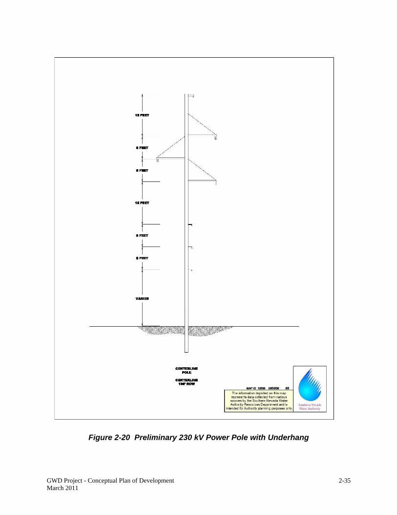
GWD Project - Conceptual Plan of Development March 2011
2-35
Figure 2-20 Preliminary 230 kV Power Pole with Underhang

GWD Project - Conceptual Plan of Development March 2011
2-36
Figure 2-21 Preliminary 69 kV Power Pole

GWD Project - Conceptual Plan of Development March 2011
2-37
Figure 2-22 Preliminary 25 kV Power Pole

GWD Project - Conceptual Plan of Development March 2011
2-38
Figure 2-23 Preliminary Primary Electrical Substation Site Plan

GWD Project - Conceptual Plan of Development March 2011
2-39
The primary substations would each be 660 feet in width and 660 feet in length, totaling 10 acres in size. Because the Spring Valley primary electrical substation would be located within the Spring Valley South Pumping Station site, additional ROW is not required for this facility. The Dry Lake Valley substation is located on lands managed by the BLM, and a permanent ROW of 10 acres is required. Temporary ROW is not required for construction of the substations.
Secondary Electrical Substations
Five secondary electrical substations are required to reduce 69 kV to 25 kV. Two would be located in Spring Valley, and one each in Snake, Cave, and Coyote Spring Valleys:
1. The Spring Valley North Secondary Substation would be located adjacent to the Spring Valley North Pumping Station (Sheet 58).
2. The Spring Valley South Secondary Substation would be located approximately 10 miles northwest of the Spring Valley South Pumping Station site, where the Spring Lateral converges with US Hwy 93 (Sheet 52).
3. The Snake Valley Secondary Substation would be located adjacent to the Snake Valley South Pumping Station (Sheet 67).
4. The Cave Valley Secondary Substation would be located on the valley floor approximately 1 mile north of Sidehill Pass (Sheet 71).
5. The Coyote Spring Valley Secondary Substation would be located on the Coyote Spring Valley Pressure Reducing Station site in northern Coyote Spring Valley (Sheet 33).
The secondary substation sites (except for the Coyote Spring Valley Secondary Substation site) are approximately 209 feet in width by 209 feet in length, or 1 acre each in size for a total of 4 acres. They would be located on lands managed by the BLM. Because the Coyote Spring Valley Secondary Substation would be located within the Coyote Spring Valley Pressure Reducing Station site (also on lands managed by the BLM), additional ROW is not required for this facility.
2.7 ACCESS ROADS
For the purposes of this document, the US Department of the Interior definitions of road types are used (Form DI 1876, Revised 8/1/97). These definitions are:
Paved Road – asphalt surfaces Improved Road – gravel surfaces, and Unimproved Road – dirt surfaces, may or may not be graded.
Access to the GWD Project facilities would be required for both construction and operation. A primary access road would be constructed within the pipeline ROW, which would be used for transport of equipment, materials, and personnel during construction. At the completion of construction, the access roads would remain for facility inspections and operations access.
The majority of the pipeline and power line alignments are located along or adjacent to existing roads, including paved highways and improved and unimproved dirt roads. Where existing roads are within the pipeline ROW, those existing roads would be used or improved as necessary. Figure 2-24 displays access road improvements for the project. Existing roads, as

GWD Project - Conceptual Plan of Development March 2011
2-40
Figure 2-24 GWD Project Access Road Improvements

GWD Project - Conceptual Plan of Development March 2011
2-41
identified on Figure 2-24 and in this discussion, refer to those roads that are currently maintained by the BLM or Counties, or are maintained as part of another ROW. Although much of the alignment follows unimproved roads, those are generally not considered in this discussion as existing roads, per the US Department of the Interior definition above.
The following access roads are required for construction and operation of project facilities:
Paved existing road – 14 miles Paved new road – 5 miles Improved existing road – 85 miles Improved new road –200 miles Unimproved existing road – 28 miles, and Unimproved new road – 20 miles.
Short segments of unimproved spur roads would also be required to access power pole sites from the primary access roads. These spur roads would be identified during project design.
Because the access roads are within the pipeline and power line ROWs, additional ROW for access roads would not be required, with two exceptions. For approximately 14 miles in northern Delamar and southern Dry Lake Valley where the pipeline and power line are not contiguous, access to the power line ROW would utilize North and South Poleline Road. For approximately 14 miles from the Gondor Substation, the power line would utilize an existing adjacent power line access road. For both of these road segments, a 20-foot ROW is requested, to allow for leveling of deep ruts and minor grading, if needed.
Access roads would be prepared at the beginning of construction by grading, installation of culverts, and graveling for improved roads. Asphalt paving would be installed on three road segments, as displayed on Figure 2-24, at the completion of construction to allow for operational access to pumping stations and the WTF/buried storage reservoir. The width of the paved and improved roads would be approximately 20 to 26 feet, to allow for two lanes of traffic. Unimproved roads would only be utilized for power line construction, and would be graded dirt roads approximately 12 feet in width.
In areas where the ROW parallels but does not encompass other existing access roads, to avoid proliferation of roads, SNWA would coordinate with the BLM at the completion of construction to determine which roads should be reclaimed. Permanent access would be required along the entire ROW, but this could be done using the improved access roads developed for construction within the ROW or other adjacent access roads if available.
In addition to the ROW access roads described above, which include new and upgraded roads, construction access for personnel, equipment, and materials deliveries would utilize existing roads and highways. These include Interstate 15, U.S. Highways 93, 6 and 50, and Nevada State Highways 168, 317, 318, 319, 320, 893, 894, and 487. Several unpaved roads currently maintained by Lincoln and White Pine Counties may also be used, including Cave Valley Road (from Ely into Cave Valley), Atlanta Road (from U.S. 93 to the pipeline alignment in Spring Valley), Stampede Road (from Pioche to the pipeline alignment in Dry Lake Valley), Pan American/Ely Springs Road (from Pioche to the pipeline alignment in Dry Lake Valley), and Alamo Canyon Road (from Alamo to the pipeline alignment in Delamar Valley). Upgrades to these roads beyond normal county maintenance activities are not anticipated to be needed; therefore additional ROW is not required.

GWD Project - Conceptual Plan of Development March 2011
2-42
2.8 COMMUNICATIONS FACILITIES
Communications facilities will be installed along with project facilities for system operation and control, data collection, communication, and security surveillance. Communication requirements would be met through use of fiber optics, radio systems and possibly cellular communications equipment installed at facility sites.
Conduits for fiber optic cables would be installed along with the proposed pipelines. The fiber optic cables would be installed underground in either the pipeline trench or adjacent access road, and would be contained within the requested ROW. No additional ROW would be required.
Facility sites may also encompass radio communication facilities. Radio communication facilities would include non-licensed, broad-spectrum radio to communicate between the facility and nearby wells. A radio antenna as high as 20 feet may be mounted on top of buildings or tanks on facility sites for relay of operation information from the well sites, if fiber optic is not available. No additional permanent or temporary ROW would be required.
2.9 FUTURE FACILITIES
Future groundwater production wells, collector pipelines, pumping stations, power facilities, and access roads will be required to develop permitted groundwater rights and convey the pumped groundwater to the primary conveyance facilities. It is anticipated that the future groundwater production wells would be located within the exploratory areas identified on Figure 2-25.
The final locations of the groundwater production wells and associated facilities to convey water into the primary system have not yet been determined. The wells will be located based on several factors, which include but are not limited to geology, hydrology, well interference studies, environmental issues, existing senior water rights, and proximity to main and lateral pipelines. Production well locations are also subject to approval by the Nevada State Engineer. Since the specific location of these facilities cannot currently be identified, SNWA has not yet requested ROW for them from the BLM. However, assumptions regarding the number of wells, length of collector pipelines, and other needed facilities have been made by SNWA so that BLM can conduct a programmatic-level environmental impact analysis of construction and operation of future facilities in addition to the site-specific analysis of proposed ROWs for primary facilities. The assumptions on future facilities are described below.
2.9.1 SNWA Future Groundwater Production Wells
Groundwater production wells will be needed to develop groundwater for the GWD Project. Sufficient wells are needed to develop permitted water rights, provide for maintenance downtime, and allow flexibility in operations for better system management. The actual number of production wells will depend upon the results of exploratory well drilling and individual well yields. For the purposes of developing programmatic-level estimates, it has been assumed that the average well yield will be approximately 800 to 1,000 gallons per minute (gpm). Considering the permitted or application quantity of water for each hydrographic basin, and adding a 20% factor for additional wells needed for maintenance and operational flexibility, the following represents an estimated number of wells per valley:

GWD Project - Conceptual Plan of Development March 2011
2-43
Figure 2-25 GWD Project Exploratory Areas

GWD Project - Conceptual Plan of Development March 2011
2-44
Spring Valley: 75 to 93 wells Snake Valley: 39 to 48 wells Cave Valley: 10 to 11 wells Dry Lake Valley: 10 to 11wells, and Delamar Valley: 10 to 11 wells.
The groundwater production wells are assumed to be located at least 1 mile apart, and could be clustered in well fields, in grids of up to 4 wells. They are anticipated to be drilled to depths between 1,000 and 2,000 feet deep, in basin fill and bedrock. The production well pumping equipment would be housed within a concrete block or pre-cast concrete structure for protection from vandalism and the elements. Electrical facilities, heating, ventilation, air conditioning equipment, and control facilities would be located in each structure.
Depending upon the water quality at each well site, groundwater treatment facilities may be required on-site, in or adjacent to the well building. Potential chlorination at well sites may consist of closed systems with exchangeable canisters, which would not be refilled on site. The chlorination facilities will comply with applicable OSHA standards. There is a potential that, if naturally-occurring arsenic is present in levels requiring treatment, some of the well sites may also require on-site arsenic removal. This cannot be determined until water quality results from the individual wells are available. However, if on-site arsenic treatment is required, it would likely be done through a small package plant which would add ferric chloride and sodium hypochlorite to precipitate the arsenic, that is then removed using filtration. Any treatment facilities would be equipped with secondary containment, in accordance with OSHA standards. Sludge generated from the filtration would be disposed of in a permitted landfill.
For the purposes of a programmatic analysis, it is estimated that a total quantity of approximately 144 to 174 groundwater production wells would be required. A permanent site ROW of 1.5 acre is anticipated for each well site. Additionally, a 0.5-acre temporary ROW at each well site is anticipated to be necessary for construction purposes. Thus, approximately 217 to 263 acres of permanent ROW and 73 to 89 acres of temporary ROW may be required for future SNWA production wells.
2.9.2 Future Collector Pipelines
Future collector pipelines would convey water from the future groundwater production wells to the main and lateral pipelines. The size of these future collector pipelines would depend upon the number of wells connected to each. It is currently anticipated that the collector pipelines may range from 10 inches in diameter where connected only to a single well, or up to 30 inches in diameter when more than 3 wells are connected.
Since the future groundwater production well sites cannot yet be identified, the sizes, routing, and distances of future collector pipelines also cannot yet be determined. However, for the purpose of a programmatic analysis, general assumptions on the potential distances of future collector pipelines have been made based on the assumed number of future groundwater production wells and known geologic and hydrologic conditions. The estimated miles of collector pipeline per valley and associated assumptions are listed below:
Spring Valley: 57 to 144 miles Assumes wells may be clustered in groups of 4 wells, with each cluster located between 3 to 6 miles from the main or lateral pipeline

GWD Project - Conceptual Plan of Development March 2011
2-45
Snake Valley: 20 to 48 miles Assumes wells may be clustered in groups of 4 wells, each cluster located between 2 to 4 miles from the lateral pipeline
Cave Valley: 30 to 88 miles Assumes individual wells may be located within 3 to 8 miles from the lateral pipeline
Dry Lake Valley: 20 to 44 miles Assumes individual wells may be located within 2 to 4 miles from the main pipeline
Delamar Valley: 50 to 110 miles Assumes individual wells may be located within 5 to 10 miles from the main pipeline
For the purposes of a programmatic analysis, it is estimated that a total quantity of approximately 177 to 434 miles of future collector pipeline would be required. The collector pipelines would require permanent ROW of up to 50 feet in width and temporary ROW of up to 50 feet in width. It is anticipated that most of these collector pipelines would be located on lands managed by the BLM. The anticipated future permanent ROW for the collector pipelines would be 1,073 to 2,630 acres, with the same estimate for anticipated future temporary ROW.
It is also assumed that temporary construction staging areas may be required along the collector pipelines, one every 3 miles. There would be an estimated total of between 59 to 145 staging areas, 1 acre each, for a total of between 59 to 145 acres of temporary ROW.
2.9.3 Future Pumping Stations
Additional pumping stations may be required to convey water from some of the future groundwater production well areas into the main and lateral pipelines. Since the locations of the production wells cannot yet be determined, the need for and siting of additional pumping stations cannot yet be determined.
For the purposes of a programmatic analysis, based upon known topography of the project area, it is anticipated that two additional pumping stations may be required to convey water from groundwater production well areas into the main and lateral pipelines. One additional pumping station each in Delamar and Dry Lake Valleys are assumed.
It is assumed that each of these pumping stations would have four pumps. The pumps are assumed to be 100 horsepower each. The facilities would also likely include a small electrical substation each to reduce power levels down to serve the facility. The permanent ROW estimated for each pumping station is 5 acres, for a total of 10 acres. The temporary ROW estimated for each pumping station is 5 acres, for a total of 10 acres.
2.9.4 Future Power Facilities
Additional distribution power lines and substations would convey power to the future groundwater production wells and future pumping stations. Since the locations of those facilities cannot yet be determined, these future power facilities also cannot yet be defined.
It is assumed that the future power lines would be overhead 25 kV power lines, routed along the future collector pipeline alignments. Additional 25 kV conductors may also need to be hung on

GWD Project - Conceptual Plan of Development March 2011
2-46
the power poles constructed as part of the proposed GWD Project primary power supply system, described in Chapter 2.6.1 above.
Using the estimated distances of future collector pipeline described above, and the anticipated future permanent ROW required for the power lines of 50 feet in width, the additional permanent ROW would total between 1,073 to 2,630 acres.
It is also assumed that additional secondary substations may be required in some areas, to reduce power from 69 kV to 25 kV to provide power to future groundwater production wells and pumping stations. The locations of these secondary substations would depend upon the specific locations of the groundwater production wells and pumping stations. However, for the purposes of a programmatic analysis, it is assumed that an additional 69/25 kV substation will be required in Delamar and Dry Lake Valleys.
Each of the future substations may require a site of approximately 1 acre. The anticipated total future permanent ROW for these additional substations would be 2 acres.
Hydroturbines may be installed in the future to generate electrical power as the water flows from higher to lower elevations. These facilities would be built below ground, with turbines placed within pipeline bypass piping. Electrical power generated by the hydroturbines would be transmitted to the project or local electrical system, where it could be used by the GWD Project or added to the utility grid. The specific locations and sizes of facilities, and quantities of power generated cannot be determined until the final pipeline design is completed. However, for the purposes of programmatic analysis, it is estimated that future hydroturbine electrical generating facilities may be installed at each of the three pressure reducing station sites that are part of the proposed action, described above. If hydroturbines are installed at each of those three locations, it is estimated that approximately 40 megawatts of power could be produced. Additional future ROW is not anticipated to be required if the hydroturbines would be sited within the pressure reducing station ROWs, but the hydroturbines would require permitting through the Federal Energy Regulatory Commission.
2.9.5 Future Access Roads
Access roads to future facilities are assumed to be located within the collector pipeline ROW. These may be either new roads or improvements to existing roads within the ROW. The road improvements may include grading, widening, and installing culverts, where needed. Gravel may be applied in some areas, if necessary, to maintain road conditions. The width of improved dirt roads would be 20 feet. It is assumed that no additional permanent or temporary access road ROWs would be needed because they would be located within the collector pipeline ROW.
2.9.6 SNWA Future Facilities Summary
A summary of the assumed future SNWA facilities by project basin is provided in Table 2-4.
2.9.7 Lincoln County Future Facilities
As described in Chapter 1.3, capacity is being provided in the GWD Project for conveyance of water for Lincoln County. Table 1-1 describes the anticipated water quantity and source basins.

GWD Project - Conceptual Plan of Development March 2011
2-47
Table 2-4 Estimated Future SNWA Facilities
Location Facility
Spring Valley 75-93 groundwater production wells 57-144 miles collector pipeline 57-144 miles 25 kV power line
Snake Valley 39-48 groundwater production wells 20-48 miles collector pipeline 20-48 miles 25 kV power line
Cave Valley 10-11 groundwater production wells 30-88 miles collector pipeline 30-88 miles 25 kV power line
Dry Lake Valley
10-11 groundwater production wells 20-44 miles collector pipeline Pumping station 20-44 miles 25 kV power line Secondary substation
Delamar Valley
10-11 groundwater production wells 50-110 miles collector pipeline Pumping station 50-110 miles 25 kV power line Secondary substation
For the 3,000 afy from Dry Lake and Delamar Valleys that SNWA would transfer to Lincoln County in accordance with their existing agreement, the potential future facilities have already been included in the SNWA future facilities estimates above. Future facilities for the remaining Lincoln County capacity cannot be identified at this time. Lincoln County has not identified specific plans or likely development areas that can be used to make reasonable assumptions for programmatic analysis. Any additional facilities required to develop that water and convey it to the GWD Project would be the subject of future ROW applications by Lincoln County Water District and require future environmental analysis.

This page intentionally left blank.

GWD Project - Conceptual Plan of Development March 2011
3-1
3.0 LAND REQUIREMENTS
The GWD Project requires ROW across federal lands managed by the BLM. ROW would be needed across State Lands, including parcels used by the Nevada National Guard and Steptoe Valley Wildlife Management Area (utility corridor). ROW would also be needed across private land, including in the northeastern Las Vegas Valley (Apex), central Coyote Spring Valley, and the City of Caliente.
SNWA submitted applications to the BLM for temporary and permanent ROW for the GWD Project on August 19, 2004 and the project was assigned case number N-78803.
3.1 PERMANENT AND TEMPORARY RIGHTS-OF-WAY
A summary of the permanent and temporary ROW required to construct and operate the GWD Project is presented in Table 3-1. This table also shows the types of facilities and acreages located on land managed by each agency and on private land. Permanent ROW is being requested for main and lateral pipelines, pumping stations, regulating tanks, a buried storage reservoir, a WTF, power lines, electrical substations, pressure reducing stations, a construction support area, and an access road. Temporary ROW is being requested for pipelines, staging areas, plant nurseries, borrow pits, some of the pumping stations, regulating tanks, and pressure reducing stations. In areas of level terrain and stable soil conditions, the amount of disturbance of the temporary ROW may be reduced; however, any potential reductions would not be known until after detailed alignment surveys and project design have been completed. Anticipated ROW for future facilities is described in Chapter 3.2.
The majority of the proposed permanent and temporary ROW located in Clark and Lincoln Counties are within the utility corridor designated by LCCRDA, which established a 2,640-foot wide corridor on public lands for utilities. LCCRDA also directed the Secretary of the Interior to grant SNWA non-exclusive ROW in perpetuity, for roads, wells, well fields, pipes, pipelines, pumping stations, storage facilities, or other facilities that are necessary for the construction and operation of a water conveyance system.
3.2 FUTURE FACILITIES
As described in Chapter 2.9, additional ROW will be required in the future for groundwater production wells, collector pipelines, pumping stations, access roads, and power facilities. These facilities cannot be identified at this time and will be requested in future applications. However, programmatic-level assumptions have been made regarding these additional future facilities. Table 3-2 describes the anticipated ROW requirements for these future facilities. It is anticipated that all of these facilities will be located on lands managed by the BLM.

GWD Project - Conceptual Plan of Development March 2011
3-2
Table 3-1 GWD Project Permanent and Temporary Right-Of-Way Estimates
Facility Permanent Rights-of-Way Temporary Rights-of-Way
Map Sheet Length Width
Total Acres
Length Width Total Acres
U.S. Bureau of Land Management Main Pipeline Spring Valley 17.0 mi 100 ft 206 17.0 mi 100 ft 206 1-5 Lake Valley 21.0 mi 100 ft 255 21.0 mi 100 ft 255 5-9 Dry Lake Valley 66.1 mi 100 ft 801 66.1 mi 100 ft 801 9-26 Delamar Valley 23.1 mi 100 ft 280 23.1 mi 100 ft 280 26-32 Coyote Spring Valley 38.9 mi 100 ft 472 40.1 mi 100 ft 486 33-44 Hidden Valley 12.2 mi 100 ft 148 12.2 mi 100 ft 148 44-47 Garnet Valley 7.1 mi 100 ft 86 7.3 mi 100 ft 88 47-49 Pahranagat Valley 6.8 mi 100 ft 82 6.8 mi 100 ft 82 32-33 Las Vegas Valley 5.7 mi 100 ft 69 5.7 mi 100 ft 69 49-50 Subtotal 197.9 mi ~ 2,399 199.3 mi ~ 2,416a Lateral Pipelines Spring Valley Lateral 38.1 mi 100 ft 462 38.1 mi 100 ft 462 1, 51-59 Snake Valley Lateral 42.8 mi 100 ft 519 42.8 mi 100 ft 519 1, 60-69 Cave Valley Lateral 22.4 mi 100 ft 272 22.4 mi 100 ft 272 70-74 Subtotal 103.3 mi ~ 1,252a 103.3 mi ~ 1,252 Temporary Construction Areas Main Pipeline Staging Areas (66)
~ ~ ~ 361 ft/ea 361 ft/ea 198 1-50
Lateral Pipeline Staging Areas (31)
~ ~ ~ 361 ft/ea 361 ft/ea 93 1, 51-58, 60-62, 64-75
Plant Nurseries (19) ~ ~ ~ ~ ~ 249 26, 29, 32-43, 45-48
Subtotal 540 Borrow Pits Spring Valley- Pit 1 ~ ~ ~ 552 ft 552 ft 7 56 Snake Valley- Pit 2 ~ ~ ~ 552 ft 552 ft 7 63 Lake Valley- Pit 3 ~ ~ ~ 552 ft 552 ft 7 8 Lake Valley- Pit 4 ~ ~ ~ 552 ft 552 ft 7 8 Cave Valley- Pit 5 ~ ~ ~ 552 ft 552 ft 7 71 Cave Valley- Pit 6 ~ ~ ~ 552 ft 552 ft 7 71 Dry Lake Valley- Pit 7 ~ ~ ~ 552 ft 552 ft 7 20 Dry Lake Valley- Pit 8 ~ ~ ~ 552 ft 552 ft 7 20 Subtotal ~ ~ ~ ~ ~ 56 Pressure Reducing Stations Dry Lake Valley North 295 ft 295 ft 2 466 ft 466 ft 5 11 Dry Lake Valley South 295 ft 295 ft 2 466 ft 466 ft 5 14 Coyote Spring Valley 1,266 ft b 242 ft b 7 1,266 ft c 206 ft c 6 33 Subtotal ~ ~ 11 ~ ~ 16 Pumping Stations Spring Valley North 466 ft 466 ft 5 466 ft 466 ft 5 58 Spring Valley South 1,615 ft 1,615 ft 60 ~ ~ ~ 1 Snake Valley North 466 ft 466 ft 5 466 ft 466 ft 5 78 Snake Valley South 932 ft 466 ft 10 ~ ~ ~ 67 Lake Valley 466 ft 466 ft 5 466 ft 466 ft 5 9 Subtotal ~ ~ 85 ~ ~ 15

GWD Project - Conceptual Plan of Development March 2011
3-3
Table 3-1 GWD Project Permanent and Temporary Right-Of-Way Estimates (Continued)
Facility Permanent Rights-of-Way Temporary Rights-of-Way
Map Sheet Length Width
Total Acres
Length Width Total Acres
U.S. Bureau of Land Management Regulating Tanks Spring Valley 295 ft 295 ft 2 466 ft b 466 ft b 3 5 Hamlin Valley 295 ft 295 ft 2 466 ft b 466 ft b 3 63 Lake Valley 295 ft 295 ft 2 466 ft b 466 ft b 3 9 Cave Valley 295 ft 295 ft 2 466 ft b 466 ft b 3 71 Dry Lake Valley 466 ft 466 ft 5 ~ ~ ~ 25 Delamar Valley 466 ft 466 ft 5 ~ ~ ~ 32 Subtotal ~ ~ 18 ~ ~ 12 Buried Storage Reservoir and Water Treatment Facility Garnet Valley 2,100 ft 1,556 ft 75 ~ ~ ~ 47 Power Lines Steptoe Valley- 230 kV 25.6 mi 100 ft 310 ~ ~ ~ 75-82 Spring Valley- 230 kV, 69 kV, & 25 kV
67.0 mi 100 ft 812 ~ ~ ~ 1-5, 51-59, 82
Spring Valley- 25 kV 4.0 mi 50 ft 24 ~ ~ ~ 58-59 Snake Valley- 69 kV & 25 kV
20.2 mi 100 ft 245 ~ ~ ~ 63-68
Snake Valley- 25 kV 3.2 mi 50 ft 19 ~ ~ ~ 68-69 Hamlin Valley- 69 kV 10.1 mi 100 ft 122 ~ ~ ~ 61-63 Lake Valley- 230 kV & 69 kV
20.8 mi 100 ft 252 ~ ~ ~ 5-9
Cave Valley- 69 kV & 25 kV
2.2 mi 100 ft 27 ~ ~ ~ 11, 71
Cave Valley- 25 kV 16.5 mi 50 ft 100 ~ ~ ~ 70-74 Dry Lake Valley- 230 kV, 69 kV, & 25 kV
67.9 mi 100 ft 823 ~ ~ ~ 11-26
Delamar Valley- 230 kV & 69 kV
22.6 mi 100 ft 274 ~ ~ ~ 26-32
Pahranagat Valley- 230 kV & 69 kV
6.0 mi 100 ft 73 ~ ~ ~ 32-33
Coyote Spring Valley- 230 kV
39.6 mi 100 ft 480 ~ ~ ~ 33-44
Hidden Valley (North)- 230 kV
12.1 mi 100 ft 147 ~ ~ ~ 44-47
Garnet Valley- 230 kV 2.5 mi 100 ft 30 ~ ~ ~ 47-48 Subtotal 320.3
mi ~ 3,739a ~ ~ ~
Electrical Substations Dry Lake Valley 660 ft 660 ft 10 ~ ~ ~ 25 Spring Valley North 209 ft 209 ft 1 ~ ~ ~ 58 Spring Valley South 209 ft 209 ft 1 ~ ~ ~ 52 Snake Valley 209 ft 209 ft 1 67 Cave Valley 209 ft 209 ft 1 ~ ~ ~ 72 Subtotal ~ ~ 14 ~ ~ ~

GWD Project - Conceptual Plan of Development March 2011
3-4
Table 3-1 GWD Project Permanent and Temporary Right-Of-Way Estimates (Continued)
Facility Permanent Rights-of-Way Temporary Rights-of-Way
Map Sheet Length Width
Total Acres
Length Width Total Acres
Access Roads Unimproved – North and South Poleline Road
14 mi 20 ft 34 ~ ~ ~ 25-28
Unimproved - Gondor Substation to Steptoe Creek
14 mi 20 ft 34 ~ ~ ~ 75-77
Subtotal BLM 7,661 acres 4,307 acres Private Caliente Construction Support Area
irregularly shaped polygon
121 ~ ~ ~ ~
Main Pipeline - Coyote Spring Valley
1.6 mi 100 ft 19 1.6 mi 100 ft 19 35-36
230 kV Power Line –Coyote Spring Valley
1.4 mi 100 ft 17 ~ ~ ~ 35-36
Main Pipeline - Apex 2.0 mi 100 ft 24 1.2 mi 100 ft 15 49 Subtotal Private 181 acres 34 acres State of Nevada 230 kV Power Line-Wildlife Management Area
1.4 mi 100 ft 17 ~ ~ ~ 80
Main Pipeline, Nevada National Guard
1.1 mi 100 ft 13 1.1 mi 100 ft 13 50
Subtotal State of Nevada 2.5 mi 30 ac 1.1 mi 13 ac PROJECT TOTAL 7,872 acres 4,354 acres Note: Total and sub-total lengths are rounded to the nearest tenth. Total acres are rounded to the nearest whole number. Map Sheet refers to the specific pages in the topographic map book. a Rounded to nearest whole acre b Not square c Not rectangular
Table 3-2 GWD Future Facilities Programmatic Estimates
Facility Permanent
ROW (acres)
Temporary ROW (acres)
Groundwater Production Wells – 144 to 174 sites 217-263 73-89 Collector Pipelines – 177 to 434 miles 1,073-2,630 1,073-2,630 Staging Areas – 59 to 145 sites ~ 59-145 Pumping Stations – 2 10 10 25 kV Power Lines – 177 to 434 miles 1,0735-2,630 ~ Secondary Electrical Substations – 2 2 ~ TOTAL 2,375-5,535 1,215-2,874

GWD Project - Conceptual Plan of Development March 2011
4-1
4.0 CONSTRUCTION
Standard construction techniques would be used for construction of the GWD Project. The general construction methods and procedures are described in this chapter. The construction contracting breakdown (i.e., number of construction contracts and sequencing) will be identified during project design.
4.1 STANDARD CONSTRUCTION METHODS
Some construction methods are common for all of the GWD facilities. These are briefly described below.
4.1.1 Surveying and Staking
Prior to ground disturbance activities SNWA would survey and stake the ROW boundaries. In addition, environmental features requiring avoidance such as sensitive plant populations, cultural sites, or other sensitive areas would be staked and fenced as necessary, in accordance with approved environmental measures and federal and state environmental conditions and stipulations. Existing utility lines, culverts, and other existing features would be staked to prevent accidental damage during construction.
4.1.2 Clearing and Grading
Clearing would occur within the staked boundaries of the permanent and temporary ROWs. Clearing would include removal of materials that would interfere with construction activities, create hazards or unsafe conditions, or impair subsequent site work. This includes cutting vegetation as approved by the BLM and removing boulders from the ROW.
After plant and topsoil salvage, the ROW would be grubbed by removing a deep surface layer that includes stumps and roots. It would be graded as necessary to provide a level working surface for the heavy construction equipment. Grading of the ROW would most likely be conducted by a bulldozer or track hoe.
Following site clearing and grading, berms and drainage ditches may be constructed to contain runoff and divert floodwaters from the construction area. The berms and ditches would be incorporated into the final grading of the facility sites, if feasible.
4.1.3 Site Fencing
Temporary security fencing would enclose facility construction sites (pumping stations, regulating tanks, buried storage reservoir, WTF, electrical substations, and pressure reducing stations) and temporary ROW, staging areas, and plant nursery areas where materials or equipment are stored. Permanent site security fencing would be installed around facility sites. The temporary and permanent security fencing would consist of standard 6- to 8-foot high chain-link fencing.
Temporary tortoise-exclusion fencing may be used in the portion of the project within desert tortoise habitat. Permanent tortoise exclusion fencing would be installed along with site security fencing around above-ground facility sites within desert tortoise habitat. Temporary orange plastic snow fencing would be used to delineate construction areas not enclosed by other fencing. This will provide construction site visibility for public safety, and also will ensure construction activities stay within the authorized ROW.

GWD Project - Conceptual Plan of Development March 2011
4-2
Temporary wildlife fencing may be installed along segments of open trench in areas of seasonal big game movement, as coordinated with BLM and Nevada Department of Wildlife (NDOW).
4.1.4 Site Access
Access roads within the ROW would be constructed at the beginning of construction activities. This would include construction or new or improvement of existing roads within the ROW, by grading, installation of culverts, and placement of crushed rock, gravel, or other stabilization materials. The final width of unimproved roads would be 12 feet; improved roads would be 20 to 26 feet.
4.1.5 Materials Storage
The temporary staging areas and portions of the temporary ROW would be used for storage of construction equipment and building materials. Equipment is expected to include, but not be limited to, graders, trenchers, haul trucks, and pickup trucks. Building materials may include, but not be limited to, sections of pipe, pumps, motors, concrete block, cement, reinforcing steel bars, gravel, and sand. Smaller items such as tools, lighting fixtures, and instruments would be stored in enclosed, portable storage units. Fuel for construction equipment and water for dust control and construction uses would also be stored at the sites according to state, federal, and local rules and regulations.
The storage areas would be fenced to secure the equipment and materials, and security at the site will be provided as necessary.
4.1.6 Sanitation, Water, and Power
Sanitary facilities and potable water storage would be provided for construction personnel. Sanitary facilities for construction personnel would be portable units.
Water required during construction would be provided from local sources, temporary construction water wells, or exploratory/production wells if available. Water may be conveyed to the construction site using water trucks or temporary above-ground water lines as necessary.
Temporary power supply would also be required during construction at some locations, including construction office trailers, pumping station and other facility sites, and the Caliente construction support area. Electrical power would be provided by portable generators, the GWD Project electrical system, or commercial power if available. If commercial power is available, it is anticipated that temporary connections would be arranged by the individual construction contractors, within the requested project ROW. Those temporary connections may be to existing regional electrical power lines operated by NV Energy, Inc., Lincoln County Power District, and/or Mount Wheeler Electric Company.
4.2 PIPELINE
Pipeline construction would be by standard cut and cover technique, involving an open trench. The only exceptions would be short segments of tunneling in areas of difficult topography and jack and bore crossings of highways and the existing Kern River natural gas pipeline.
4.2.1 General Pipeline Construction Techniques
In addition to the measures described in Chapter 4.1 above, the following general construction techniques would apply to pipeline construction.

GWD Project - Conceptual Plan of Development March 2011
4-3
Trenching
Excavators, backhoes, track hoes, or other similar equipment would be used to dig the trench. As shown on Figure 2-8, the pipe trench top width would normally vary from 50 to 70 feet wide, with side slopes from 0.75:1 to 2:1, but could be as narrow as 15 feet wide depending upon topography, soils, or other site-specific conditions (e.g., see 4.2.2, Steep Terrain, below). The depth from the ground surface to the top of the pipe would be a minimum of 6 feet. Material excavated from the trench would be stockpiled adjacent to the trench.
In Pahranagat Canyon, or other areas where construction excavation may be limited due to topographic constraints, pipeline excavation may use trench boxes or other structural trench support measures, in compliance with Occupational Safety and Health Administration standards.
The length of open trench segments would be managed to minimize the duration of construction disturbance. Longer stretches of open trench may be needed in some areas to keep the construction period shorter. Multiple construction contracts may be underway during the same time period, however, it is not anticipated that more than 2.5 miles of continuous trench from an individual contract would be open at any time.
Bedding
Engineered bedding materials would be laid in the bottom of the pipeline trench. These bedding materials may consist of screened or otherwise processed excavated materials or materials imported from borrow pits. Alternatively, bedding materials may be a cement-based Controlled Low Strength Material. Bedding materials may be laid up to the mid-point around the pipe (lower pipe zone).
Pipe Laying and Welding
Pipe sections would be transported to the construction site via truck and strung along the trench. The pipe sections would be lowered into the trench and the sections welded together. All welds would be visually inspected and tested using non destructive and approved testing methods. Welds that do not meet established specifications would be repaired or removed. Once the welds are approved, the welded joints would be tape wrapped and mortar coated. Wrapped and coated joints would be inspected for faults or voids in the coating. Appurtenant structures would then be affixed to the pipe.
Upper Pipe Zone Backfilling
After the pipe and bedding material have been placed in the trench, the area immediately around the upper sides of the pipe to not less than 12 inches above the top of the pipe (upper pipe zone) would be backfilled and compacted. Materials used for backfill may include Controlled Low Strength Material, excavated soils, or materials imported from borrow pits that have been screened or otherwise processed. The imported backfill material would be crushed rock, gravel, and/or sand up to 3/8 inch in diameter.
Trench Backfill
After upper pipe zone backfilling, the remainder of the trench would be backfilled to approximately finished grade using a back hoe, track hoe, bulldozer or similar equipment. Material that is 6 inches in diameter or less would be used as backfill. Trench backfill would meet best management practices, and be:

GWD Project - Conceptual Plan of Development March 2011
4-4
Selected or processed to be clean, well graded earth material Free of excessive fine particles, vegetation, or other deleterious materials Compacted in place for maximum pipeline stability, and Moistened or dried before backfilling to ensure optimum moisture content.
Excess soils not used to refill project borrow pits would be evenly distributed over the ROW. It is preliminarily estimated that the pipeline excavation could generate approximately 46 million cubic feet of excess soil materials. Respreading of this material across the ROW at the completion of construction could add approximately 3 inches to the ground surface. The ground surface would be graded as close as possible to pre-existing contours and to blend with adjacent land surface, and this increase is not anticipated to be visually discernable. Following grading of the ROW, topsoil replacement and vegetation restoration would be conducted in accordance with an approved Restoration Plan.
Construction Water
Water would be required for construction activities, including dust control, pipe bedding, trench backfill compaction, and hydrostatic testing. SNWA has assumed that this water would be obtained from existing wells or exploratory wells that are available at the time of construction. A construction water supply well would be needed approximately every 10 miles along the pipeline alignment, and would need to be capable of a peak rate of 800 gallons per minute. It is estimated that between 5.5 and 8.7 million gallons of construction water would be needed for every mile of pipeline, with less water needed for dust control in wet winter conditions. SNWA anticipates that existing and future exploratory wells capable of that peak rate would likely be sufficiently available. If needed, additional temporary construction water wells would be drilled within the construction staging areas. Additional ROWs or other water supplies for construction water would not be needed.
Hydrostatic Testing
Hydrostatic testing would need to be conducted to pressure test the completed pipeline. The testing would be conducted in segments, when major portions of the pipeline are completed. Water used for the hydrostatic testing is anticipated to be obtained from existing groundwater wells or other permitted sources.
Water from hydrostatic testing of individual pipeline segments would either be released into a downstream pipeline segment for continued hydrostatic testing or would be discharged through a drain valve into adjacent dry washes. Discharges into dry washes would be conducted in accordance with requirements of a State of Nevada temporary discharge permit. A diffuser or similar device would be used to reduce the potential of discharges to erode and scour dry washes. The specific discharge locations cannot be determined until facility design is completed. A detailed hydrostatic testing discharge plan will be prepared and approved by the BLM prior to conducting the testing.
Hydrostatic testing for the southern portion of the project, between Delamar regulating tank and the pipeline terminus, is anticipated to be conducted in two segments, to save water and minimize the need for discharge. The first would be between the Delamar regulating tank and the buried storage reservoir, and the second would be between the buried storage reservoir and the pipeline terminus. The water used for the testing could be discharged at either the buried storage reservoir site or the terminus. If possible, the hydrostatic testing would be managed to reuse water from testing of the first segment for the second segment, thereby avoiding the need

GWD Project - Conceptual Plan of Development March 2011
4-5
for discharge at the buried storage reservoir. Discharge at the terminus would likely be into the existing storm drain system.
Hydrostatic testing for the northern portion of the project, from the Delamar regulating tank northward, would also be conducted in segments to minimize discharges. Specific potential discharge locations cannot yet be identified, but hydrostatic testing would likely be managed by major pipeline components, as identified on the project schedule. Discharges would likely be into adjacent dry washes.
Discharges into dry washes would be conducted in accordance with requirements of a State of Nevada temporary discharge permit. A diffuser or similar device would be used that is designed to reduce the potential of discharges to erode and scour dry washes.
4.2.2 Special Pipeline Construction Techniques
In some areas, special pipeline construction techniques may be necessary. These are described below.
Highway Road Crossings
The pipeline would cross U.S. Highways 93, 50, and 6. Jack and bore construction, which is a method for installing a casing below grade without trenching, is anticipated for these crossings. Jacking and boring pits, approximately 100 feet long by 20 feet wide, would be placed on either side of the highway (within the requested temporary or permanent ROWs). Minimum depth to the top of the pipe under highways would be 6 feet. Crossings of US highways would meet all federal Department of Transportation requirements. Jack and bore may also be used to cross state highways (SR 487, 215) depending on Nevada Department of Transportation requirements.
Utility and Other Crossings
The pipeline would cross the existing Kern River natural gas pipeline in two places in north-eastern Clark County. Crossings would be done by jack and bore construction, as described above. No railroads would be crossed by the pipeline.
Steep Terrain
There are areas of steep terrain along the pipeline route in the Pahranagat Narrows area. The excavated construction trench may be narrowed through this stretch, and trench boxes or other structural trench support measures may be used, in compliance with Occupational Safety and Health Administration standards. Other short areas of jack and bore may be needed where the pipe depth would be over 40 feet due to topography and need to maintain an adequate hydraulic profile.
Water Crossings
For stream crossings which may have water flow (Snake Creek is a perennial creek, and Big Wash and Lexington Creek may contain water during high flow years; all are in Snake Valley), the pipeline construction technique could be jack and bore beneath the water, or open cut with temporary diversion of water flow, in accordance with US Army Corps of Engineers and State of Nevada permit requirements, as applicable. There are no wetlands that would be crossed by the requested ROWs.

GWD Project - Conceptual Plan of Development March 2011
4-6
Ephemeral Wash Crossings
Crossings of dry washes would be by standard cut and cover, with implementation of erosion control measures (described in Appendix A, Stormwater Erosion Control) in accordance with a project approved Storm Water Pollution Prevention Plan (SWPPP) and as required under the Clean Water Act Section 404 permit.
Residential Areas
There are no residential areas along or adjacent to proposed pipeline routes. Thus, no special construction techniques for residential areas are necessary.
Blasting
Blasting may be necessary when caliche (a hardened deposit of calcium carbonate) or large boulders are encountered during excavation. Until detailed geotechnical investigations and pipeline design are completed, it is not known if any blasting would be required. If blasting is required, a Blasting Plan would be prepared and submitted for BLM approval. Qualified blasting specialists would be utilized to ensure that all blasting is conducted according to regulations and the approved plan.
Tunneling
An approximately 2-mile length of the pipeline in the Apex area of northeastern Clark County would be tunneled due to extremely steep and rugged terrain. The tunnel would be located on both BLM and private lands and is anticipated to be excavated using a tunnel boring machine. Tunnel depth may vary from less than one-hundred to several hundred feet. Depending upon final design, one or more access shafts may need to be constructed from the surface to the below-ground tunnel. Soils from the tunnel excavation would be used for pipeline backfill or site grading elsewhere on the project, and a soil disposal area is not anticipated to be needed.
Tunnels less than 500 feet long would generally be constructed using jack and bore techniques, and longer tunnels may require manually-operated equipment or tunnel boring machines. Tunnels may be concrete-lined, depending on site-specific conditions. Any required tunneling activities, including access shafts, would be conducted within the ROW.
4.3 PUMPING AND PRESSURE REDUCING STATIONS
Following site clearing and grading, the plumbing, power conduits and other infrastructure beneath the pumping and pressure reducing station floors would be constructed. The foundations of the structure would then be constructed, followed by the floors, walls and roof. Mechanical and interior components may be constructed in conjunction with the building or after it is completed.
The facilities would be inspected and a certificate of occupancy issued according to required county regulations. Permanent power would be connected from the GWD Project electrical system to the facilities’ electrical systems. The pumps, valves, and appurtenances within each facility would be connected to the incoming and outgoing water pipelines, and the system tested in its entirety. Temporary electrical, water, and sanitary systems not converted into permanent facilities would be removed. Final grading and site restoration of the temporary ROW would be completed in accordance with the approved Restoration Plan.

GWD Project - Conceptual Plan of Development March 2011
4-7
4.4 REGULATING TANKS
Following site grading and leveling, the regulating tanks would be constructed of steel (above or below ground) or concrete (below ground). Steel tanks would be built on a concrete foundation, with steel panels welded and bolted together to form the floor, walls, and roof. Concrete tanks may be constructed as cast-in-place structures. Overflow pipes, drain pipes, inlet and outlet pipes, ladders, and other appurtenances would be erected at varying periods during construction.
At the completion of construction, the tanks may be hydrostatically tested. Hydrostatic testing of regulating tanks would be coordinated with testing of the pipelines, if feasible, to conserve the amount of water needed for testing. The volume of water discharged from hydrostatic testing would be dependent upon the final size of each tank, which will not be determined until project design. However, it is anticipated that the maximum volume of water discharged per tank would be 3 to 10 million gallons. Water would be discharged into adjacent dry washes or drainage channels, with the flow rate not exceeding the 2 to 5 year storm event. The water would be discharged in a controlled manner, in accordance with the requirements of a temporary discharge permit and the hydrostatic discharge testing plan. Alternately, testing water may be discharged to downstream piping.
4.5 WATER TREATMENT FACILITY/BURIED STORAGE RESERVOIR
Following site clearing and grading, the plumbing, power conduits and other infrastructure beneath the WTF and reservoir floors would be constructed. The foundations would then be constructed, followed by the floors, walls, and roof. Ancillary components inside and outside of the facilities would be constructed once the concrete structures are constructed.
The WTF mechanical and interior components would consist mainly of storage tanks for wet and dry treatment chemicals, treatment contact vessels, metering and transfer pumps, meters and gauges, and piping. The WTF would be inspected and a certificate of occupancy issued according to applicable county regulations.
Hydrostatic testing of the reservoir would be coordinated with the testing of the pipelines, if feasible, to conserve the amount of water needed for the testing. It is anticipated that approximately 10 to 40 million gallons of water may be discharged from hydrostatic testing of the reservoir. Water would be discharged into adjacent dry washes or drainage channels at a rate not exceeding the 2 to 5 year storm event. The water would be discharged in a controlled manner, in accordance with the requirements of a temporary discharge permit and the hydrostatic discharge testing plan.
Permanent power would be connected from the GWD Project electrical system to the WTF electrical system. The internal piping system would be connected to the incoming and outgoing water pipelines and the system tested in its entirety. Temporary electrical, water, and sanitary systems not converted into permanent facilities would be removed. Final grading and landscaping would follow.
4.6 POWER FACILITIES
Construction of the different power components is described below.
Power Lines
Unlike other facilities, clearing and grading of the entire power line ROW would not be required. Following identification of specific power pole locations, work areas of approximately 100 feet

GWD Project - Conceptual Plan of Development March 2011
4-8
by 200 feet around each power pole structure would be cleared. An access road or access road spur to the pole locations would be rough graded.
A truck-mounted rotary auger would bore pole locations to a depth of approximately 15 feet. After hardware and insulators are installed on each pole, the poles would be erected on site and placed using a truck-mounted crane. Soil removed by the auger would be used to backfill the space around the pole. Excess soil cuttings would be spread around the pole site, within the ROW. Where additional strength is needed to support a power pole, a concrete foundation may be used to reinforce a bore hole, or concrete may be used to backfill a hole after pole installation.
Conductor wires would be strung using tensioning equipment. Tensioning equipment would require 100-foot by 200-foot work areas, approximately 1 mile apart. A large spool of conductor wire would be mounted on a truck at one work area, and pulling equipment would be located at the next work area. In this manner, conductor wire can be pulled onto the series of power poles within the 1-mile pulling distance in a single operation. Stringing conductor wires over US Hwys 93, 50 and 6, and other frequently traveled roadways may require the erection of temporary guard structures to elevate conductor wires to a sufficient height to avoid traffic conflicts. Temporary guard structures would be constructed using wood poles in H-frame configuration.
After power lines are connected to substations and facilities, the lines would be energized. Electrical equipment on each power line network would be tested before it is entered into service.
Substations
Following site clearing and grading, berms and drainage ditches would be constructed to contain runoff and divert floodwaters from the substation sites. For each substation, concrete pads would be constructed for transformers. Each pad would include a curb around the perimeter for spill containment. Concrete foundations would be constructed for electrical structures. Electrical conductors would be strung using pulleys. A concrete block control building would be constructed to house controls and relay equipment.
Substations would be enclosed by security fencing, typically 8-foot high chain link, with a locked gate. Once the substations are constructed, they would go through a testing and commissioning process, in accordance with applicable electrical industry standards, codes and procedures.
4.7 ACCESS ROADS
Access road construction would occur at the beginning of pipeline and facility construction in the area served by the access road. All roads would first be graded to level the surface as necessary. Gravel would be applied in areas needed to maintain road conditions during construction activities. In areas of improved roads, culverts would be installed where needed, and paving applied to the identified road segments.
Public use and access on existing roads and highways would not be impeded by construction. Signs and persons with flags would be used as necessary to direct traffic in accordance with all applicable Nevada Department of Transportation, county, and local laws and ordinances.
If roads within the project ROWs are temporarily widened for use during construction, those widened areas would be restored along with other ROW restoration. The final width of
GWD Project - Conceptual Plan of Development March 2011
4-9
unimproved roads would be 12 feet, and improved roads including paved roads would be 20 to 26 feet in width.
4.8 COMMUNICATIONS FACILITIES
Fiber optic cables would be buried in the ground in the pipe trench, adjacent to the pipeline within the project ROW. In the trench, the cable would be buried at least 6 feet deep, or buried in the ground adjacent to the trench the depth would be approximately 3 to 4 feet. The fiber optic cables would be routed to the facilities where they would be connected to the facility communications systems.
4.9 CONSTRUCTION SCHEDULE, WORKFORCE, AND EQUIPMENT ESTIMATES
A detailed construction schedule will be determined during project design, as individual construction contracts are identified. However, for the purposes of conducting the environmental analysis, assumptions have been made regarding the construction schedule, workforce, and equipment needs.
4.9.1 Construction Schedule
Construction of the GWD Project facilities under this ROW request is planned to begin upon receipt of the ROW grant in 2012 and reach completion in 2023. This construction schedule is the earliest that construction of the project would begin. Construction could be deferred for several years, if drought conditions on the Colorado River do not risk a restriction of SNWA's other water supplies. In the absence of drought, the project would be constructed such that groundwater pumping could begin by 2020.
Various components of the GWD Project may be constructed simultaneously throughout the project area during this period. Table 4-1 provides a preliminary construction schedule for the GWD Project. The access roads would be constructed in conjunction with the pipelines, and so are not separately listed on the table.
4.9.2 Workforce Estimates
A preliminary estimate of the peak workforce required to construct the GWD Project facilities has been developed for the purposes of environmental analysis. Although the specific number of construction contracts and associated contracting schedule has not yet been developed, assumptions were made based upon the preliminary construction schedule and typical construction workforce on other SNWA projects. The estimated peak construction workforce by year is presented in Table 4-2. Estimates for the main pipeline and power line are shown over the entire construction period, because locations and limits of individual construction contracts have not yet been determined. The lateral pipelines and facility sites were grouped into eight general geographic regions for manageability.

GWD Project - Conceptual Plan of Development March 2011
4-10
Table 4-1 Preliminary Construction Schedule for Proposed Facilities
Facility
Anticipated Construction
Start (Quarter/Year)
Anticipated Construction
Finish (Quarter/Year)
Main Pipeline South Terminus to Reservoir/Water Treatment Facility Q2/2012 Q2/2016
Reservoir/Water Treatment Facility to Delamar Valley Regulating Tank Q3/2013 Q3/2015
Delamar Valley Regulating Tank to Dry Lake Valley Regulating Tank Q4/2014 Q3/2016
Dry Lake Valley Regulating Tank to Muleshoe Regulating Tank Q3/2015 Q2/2017
Muleshoe Regulating Tank to Spring Valley Regulating Tank Q4/2016 Q3/2018
Spring Valley Regulating Tank to Spring South Pump Station Q2/2017 Q4/2018
Lateral Pipelines Cave Valley Lateral Q2/2016 Q2/2017
Spring Valley South Lateral Q2/2017 Q3/2019
Spring Valley North Lateral Q3/2019 Q1/2020
Snake Valley South Lateral Q3/2021 Q2/2023
Snake Valley North Lateral Q2/2022 Q4/2023
Pump Stations Lake Valley Q4/2015 Q2/2017
Spring Valley South Q1/2017 Q1/2019
Spring Valley North Q4/2018 Q1/2020
Snake Valley South Q3/2021 Q1/2023
Snake Valley North Q3/2022 Q4/2023
Pressure-Reducing Stations Coyote Spring Valley Q3/2013 Q1/2014
Dry Lake Valley South Q2/2014 Q4/2014
Dry Lake Valley North Q4/2014 Q3/2015
Buried Storage Reservoir (On same site as Water Treatment Facility) Q3/2014 Q4/2016
Water Treatment Facility (On same site as Buried Storage Reservoir) Q2/2015 Q4/2016
Power Facilities Transmission, distribution, and substations Q2/2014 Q4/2018
RT – Regulating Tank PS – Pumping Station PRS – Pressure Reducing Station

GWD Project - Conceptual Plan of Development March 2011
4-11
Table 4-2 Estimated Peak Construction Workforce by Year
Construction by Region
Year
2012 1013 2014 2015 2016 2017 2018 2019 2020 2021 2022 2023
Main Pipeline 5 154 332 451 364 267 130
Main Power Line 88 89 89 89 48
Snake North Facilities & Snake Lateral 98 135
Snake South Facilities & Snake Lateral 272 317 131
Spring North Facilities & Spring Lateral 41 42 132 71
Spring South Facilities 71 139 234 151
Lake & Cave Facilities, Cave Lateral 72 72
Dry Lake Facilities 45 46 32
Delamar & Coyote Spring Facilities 99 104
Hidden, Garnet, & Las Vegas Facilities 70 203 242 285
Estimated Total per Year 5 224 767 932 913 608 454 283 71 272 415 266
Construction Equipment
Estimates of the types of construction equipment that may be required for project construction have been developed for the purpose of environmental analysis. The estimated construction equipment types are listed in Tables 4-3 through 4-5. The categories shown include the following components:
Pipelines – includes pipelines, valves, regulating tanks, and pressure reducing stations
Power Lines – includes power poles and power lines, and Other Facilities – includes the WTF, buried storage reservoir, pumping stations,
and substations.

GWD Project - Conceptual Plan of Development March 2011
4-12
Table 4-3 Estimated Personnel and Equipment Required for Pipeline Construction
Personnel Equipment
Mai
n Pi
pelin
e
Lat
eral
Tun
nel
Mai
n Pi
pelin
e
Lat
eral
Tun
nel
General Foreman 1 1 1 Grader 2 2 2 Foreman 3 2 3 Haul truck 4 4 6 Project Manager 1 1 1 Fork Lift 2 2 2 Project Engineer 1 1 1 Bulldozer 2 2 2 ROW Crew 5 5 Excavator 2 2 2 Pipe Stringing 5 4 Loader 4 4 4 Excavation 10 8 Crane 2 2 2 Bedding 7 4 Generator, Large 1 1 2 Pipe Laying 7 4 Generator, Small 2 2 4 Welders 12 8 2 Welding Rigs 12 8 2 Diapers 7 6 Plate Compactor 6 6 Backfill Pipe Zone 10 8 Roller Compactor 2 2 1 Final Backfill 6 4 Fuel Truck 1 1 2 Interior crew 5 4 Pickup Truck 8 6 6 Appurtenances 7 5 Water Truck 2 2 2 Safety 3 Drill Rig 2 Operators 10 TBM 1 Mechanics 4 Grout Plant 1 Teamsters 22 Conveyor System 1 Laborers 18 Dewatering System 2 Electrician 3 Muck Buckets 2 Carpenters 4 Muck Cars 4 Lead Miner 3 Air Compressors 2 Oiler 3 Hammer Drill 1 Hoist 2 Total 87 65 78 52 46 57

GWD Project - Conceptual Plan of Development March 2011
4-13
Table 4-4 Estimated Personnel and Equipment Required for Power Line and Power Substation Construction
Personnel Equipment
Pow
er T
rans
mis
sion
Pow
er S
ubst
atio
ns
Pow
er T
rans
mis
sion
Pow
er S
ubst
atio
ns
Gen Foreman 1 1 Excavator 3 Foreman 2 2 Bulldozer 1 Project Manager 1 Grader 1 Project Engineer 1 1 Haul Truck 6 3 Safety 1 1 Crane 2 2 Operators 8 11 Loader 1 2 Mechanics 2 1 Roller Compactor 1 Teamsters 14 5 Fork Lift 1 1 Electrician 20 20 Generator, Large 1 Generator, Small 2 Plate Compactor 1 Fuel Truck 1 1 Pickup Truck 8 4 Water Truck 1 1 Auger Drill 3 1
Bucket Truck 6
Total 49 43 32 22

GWD Project - Conceptual Plan of Development March 2011
4-14
Table 4-5 Estimated Personnel and Equipment Required for Facility Construction
Personnel Equipment
Pum
p S
tati
on
Ter
min
al R
eser
voi r
Reg
ulat
ing
Tan
k
Wat
er T
reat
men
t Fac
ilit
y
Pre
ssur
e R
educ
ing
Sta
tion
Pum
p S
tati
on
Ter
min
al R
eser
voir
Reg
ulat
ing
Tan
k
Wat
er T
reat
men
t Fac
ilit
y
Pre
ssur
e R
educ
ing
Sta
tion
Gen Foreman 1 1 1 1 1 Excavator 2 4 2 2 Foreman 3 3 2 3 3 Bulldozer 1 2 1 1 1 Project Manager 1 1 1 1 Grader 1 2 1 1 Project Engineer 1 1 1 1 1 Haul Truck 4 8 6 4 4 Safety 1 1 1 1 1 Crane 2 3 2 2 2 Operators 12 20 6 12 12 Loader 2 3 2 2 Mechanics 1 2 1 1 1 Roller Compactor 2 3 1 2 2 Teamsters 7 11 4 7 7 Fork Lift 2 3 1 2 2 Iron Workers 6 10 2 6 6 Generator, Large 1 2 1 1 Welders 3 2 1 3 3 Generator, Small 2 4 2 2 2 Laborers 10 16 6 10 10 Plate Compactor 2 4 2 2 Electrician 12 4 2 12 12 Welding Rigs 3 2 3 3 Carpenters 8 14 4 8 8 Fuel Truck 1 1 1 1 1 Millwrights 2 1 2 2 Pickup Truck 8 6 8 8 8 Pipe Fitters 6 3 2 6 6 Water Truck 2 2 1 2 2 Auger Drill 3 Bucket Truck 6 Total 74 90 33 74 74 35 49 32 35 35

GWD Project - Conceptual Plan of Development March 2011
4-15
4.9.3 Future Facilities Construction
As described above, the final locations of groundwater production wells and associated future facilities have not yet been determined. Thus, a specific schedule for construction of the future facilities cannot be developed. For the purposes of a programmatic-level analysis, SNWA has identified a potential timeline for construction of the future facilities and groundwater development. Project construction could be accelerated or delayed from this schedule, dependent upon whether drought conditions on the Colorado River affect SNWA’s other water supplies.
Figure 4-1 GWD Project Potential Timeline

This page intentionally left blank.

GWD Project - Conceptual Plan of Development March 2011
5-1
5.0 OPERATION AND MAINTENANCE
The GWD Project would be operated and maintained by SNWA safely, correctly, and within environmental requirements of the BLM ROW grant and other federal, state, and local agency requirements. In addition to routine operation of facilities, activities would include remote and on-site monitoring of system functions, inspection of the pipelines and facilities, regular maintenance of equipment, repairs conducted as needed, and responses to emergency conditions should they occur. All operation and maintenance activities would be confined to the permanent ROW. If additional ROW is required for unforeseen circumstances, SNWA would request it from the BLM.
A detailed operations and maintenance schedule would be developed for the project during facility construction and prior to operation. Facilities would periodically be visually inspected to ensure proper functioning, with emphasis on major facilities and mechanical equipment. On-site personnel and SNWA’s remote monitoring and control system would track and manage facility functions.
5.1 PIPELINES
Operational activity on the pipeline would be primarily include maintenance of the ROW and inspection, repair, and cleaning of the pipeline and appurtenances. ROW maintenance may include application of herbicides to control noxious and non-native invasive weeds. Aerial and ground inspections by pipeline personnel would identify any areas of exposed pipeline and appurtenances, erosion, unauthorized ROW encroachment, or any other conditions that could present a safety hazard or require preventive maintenance or reporting. The pipeline route would likely be visually inspected at least monthly, using the access roads within the ROW. No off-road or overland travel would occur for routine inspections.
In the unlikely event of a major system rupture or malfunction resulting in the discharge of water, pressure sensors installed on the system would detect the pressure loss, and the groundwater pumps and wells would begin an automatic, sequenced shut down. Shut down would be sequenced to avoid buildup of dangerous pressures in the pipeline and other facilities. Valve closing times would vary based on location and system conditions, but are estimated to vary from 15 to 25 minutes. For a major system failure, alarms would sound at manned facilities along the pipeline alignment and at the SNWA operations centers. A plan of action to investigate the source of the problem would commence immediately.
Depending upon the location of the incident, a manned response could take up to 3 hours to reach remote areas. The quantity of water that might be released in the unlikely event of a pipeline rupture or valve failure cannot be precisely quantified, as it would depend upon the type and extent of a break/failure, along with the location of the break within a pipeline segment and its distance from the closest upstream and downstream isolation valves. However, for the purposes of analysis, assuming an extremely unlikely but worst possible scenario of catastrophic failure with complete severing of the largest diameter pipeline over a 10 mile stretch, the maximum quantity of water that could be discharged would be 24.6 million gallons. This assumption uses a 35 minute response time (10 minutes for the system to identify the location and 25 minutes to close the nearest upstream isolation valve), and does not consider the effect of decreasing flow rate during the valve closure timeperiod on the total discharge volume. All of that quantity of water is unlikely to be released, even in an emergency scenario, since immediate

GWD Project - Conceptual Plan of Development March 2011
5-2
actions would be taken through the automated system and on-site response to control and repair the leakage.
In the event pipeline repairs are necessary, they could take between 2 hours and one week to complete, depending upon the magnitude of the necessary repair. A repair crew could be between 2 and 10 people, and they would utilize equipment similar to those identified in Tables 4-3 through 4-5.
5.2 PUMPING STATIONS, REGULATING TANKS, AND PRESSURE REDUCING STATIONS
Pumping stations, regulating tanks, and pressure reducing stations would be remotely monitored to ensure proper operation, including controlling the valves to maintain water flow through the system. Visual inspections of facilities would vary depending upon facility, size, location, and amount of use. Pumping stations would likely be visually inspected daily, regulating tanks weekly, and pressure reducing stations 2-3 times per week. Routine inspections would use existing access roads and designated access roads within the ROW. No off-road or overland travel would occur for routine inspections.
The maintenance yard adjacent to the Spring Valley South Pumping Station would be used to conduct maintenance and repair activities at that pumping station and to support repairs for other facility sites as needed. Less extensive on-site maintenance and repair may also occur on individual facility sites, as necessary and feasible.
5.3 WATER TREATMENT FACILITY/BURIED STORAGE RESERVOIR
An integrated control system would be developed for operation of the WTF, which would be coordinated with SNWA’s other water supply facilities. Shifts of three to six operational personnel are anticipated to be present at the WTF daily.
In addition to remote system monitoring, SNWA would conduct routine visual inspections of the WTF and buried reservoir. Valves to maintain water levels in the reservoir would be visually checked and remotely controlled.
Operation of the WTF would require delivery and use of chemicals for water treatment. Table 5-1 shows the major chemicals potentially needed for water treatment, along with potential on-site storage quantity, the approximate number of days of supply, and delivery frequency. The final list and quantities of chemicals would be determined after water quality testing of groundwater production wells and design of the facility are completed.
It cannot currently be determined if arsenic treatment may be required. This would not be known until water quality results from production wells are available. If arsenic treatment is needed, the treatment process would likely involve the addition of ferric chloride and sodium hypochlorite. Any sludge generated from the arsenic treatment would be disposed of in an approved landfill.

GWD Project - Conceptual Plan of Development March 2011
5-3
Table 5-1 Potential Water Treatment Chemicals
Chemical Stored Quantity Days of Supply Monthly Truck
Trips Sodium Chloride (salt) 66 tons 30 4
Sodium Hypochlorite 64,000 gallons generated on-site NA
Zinc Orthophosphate (inhibitor) 3,200 gallons 30 1 Hydrofluorosilicic Acid (23%
liquid) 11,200 gallons 30 4
5.4 POWER FACILITIES
The power facilities would be monitored remotely to ensure proper operation and that adequate power is available. The structures, insulators, conductors, and related hardware would be visually inspected annually. Substations would be visually inspected monthly. Additional visual inspections may be carried out following severe weather or other events that could damage the facilities. Maintenance would be performed on an as-needed basis.
5.5 ACCESS ROADS
Improved and paved access roads within the ROW would be maintained throughout facility operation. This may include pavement repair and additional grading and graveling of improved roads, as needed to maintain road integrity.
5.6 COMMUNICATIONS FACILITIES
Routine yearly inspections would occur for fiber optic communication facilities. The buried fiber optic cables would only be removed and replaced upon system failure. Communications facilities located within project facility sites would be visually inspected during regularly scheduled site visits.
5.7 SECURITY
Security staff would conduct inspections on unmanned facility sites approximately 2-3 times per week. Security inspections would utilize existing roads (dirt or paved) and/or be accessed on foot. There would be no off-road or overland travel. These patrols would be aided by remote passive security cameras that allow for enhanced monitoring of the facilities.

This page intentionally left blank.

GWD Project - Conceptual Plan of Development March 2011
6-1
6.0 TERMINATION
The ROW granted for the GWD Project would be in accordance with the Federal Land Policy and Management Act of 1976, Southern Nevada Public Lands Management Act of 1998, and LCCRDA. In accordance with LCCRDA and the Southern Nevada Public Lands Management Act, ROW is granted in perpetuity. Termination and abandonment of the GWD Project is not anticipated, unless exceptional circumstances should arise. In such a case, the termination and abandonment would be subject to approvals by the BLM and other federal and private land managers. Termination and abandonment plans would be written in accordance with current management procedures and submitted to the BLM in advance of any associated actions. If the Project was to be abandoned in part or in whole, the ROW would revert to the land managing agencies. In the event that upgrade or replacement of facilities is required, SNWA would coordinate with the BLM prior to initiating major construction in accordance with applicable stipulations of the final ROW grant.

This page intentionally left blank.

Appendix A GWD Project - Conceptual Plan of Development March 2011
A-1
APPENDIX A – APPLICANT ENVIRONMENTAL PROTECTION MEASURES
SNWA has identified environmental protection measures that will be implemented as part of the construction and operation of the GWD Project. These applicant-committed measures include design features, best management practices, monitoring, standard operating procedures, and other practices. They also include measures SNWA has previously agreed upon in stipulations or other agreements with Federal, State, or local agencies and entities, and those required by Nevada State Engineer permit conditions.
The applicant-committed environmental protection measures have been divided into three categories: 1) detailed measures associated with the current ROW request, 2) programmatic measures associated with future ROWs, and 3) landscape-scale measures associated with water related effects of groundwater development. The landscape-scale measures are intended to address the direct and potential indirect effects of groundwater withdrawals. Because of inherent uncertainties in predicting effects of groundwater withdrawals, SNWA has developed an adaptive management approach for use in determining whether and how additional environmental protection measures should be implemented.

This page intentionally left blank.

Appendix A GWD Project - Conceptual Plan of Development March 2011
A-2
A. ROW Measures
1. GENERAL CONSTRUCTION PRACTICES
Planning and Permitting
A.1.1 SNWA will complete a detailed Plan of Development (POD) for the final project approved by the BLM. More than one POD may be developed if the project is constructed in phases. The detailed POD(s) will incorporate mitigation contained in the Record of Decision and provide detailed project design and construction specifics, including but not limited to construction contract timing and phasing, construction access roads and ROW entry points, locations of refueling and equipment maintenance, hydrostatic discharge locations, areas of fencing for special status species, and other details. The POD(s) shall contain detailed plans, including, but not limited to, those listed below. The BLM will review and approve the POD(s) prior to notice to proceed for any surface disturbance activity.
Agency Coordination Plan –primary contacts including BLM authorized officer, SNWA, construction management, environmental compliance inspection contractor, and construction contractors; identification of reporting procedures and frequency
Blasting Plan – identification of areas where blasting may be needed, blasting procedures, control of explosives, necessary permits, noticing, and reporting.
Construction Plan – construction schedule and sequencing, temporary use areas, maintenance and refueling areas, access roads, borrow pits, handling of unanticipated discoveries, best management practices, vehicle/equipment washing locations, etc.
Construction Traffic Management Plan – measures to reduce and manage construction traffic.
Dust Control Plan – air quality standards and permits, dust control measures, water sources, air quality monitoring, and reporting.
Emergency Response Plan – emergency contacts, notification procedures, available resources, and emergency procedures.
Fire Prevention Plan – measures to prevent accidental fire during all phases of construction, and initial response actions.
Hydrostatic Discharge Plan – sources and volumes of water, discharge locations and quantities, erosion and flow control measures, necessary permits, and reporting.
Integrated Weed Management Plan – identification of areas with noxious/invasive weeds, treatment and control measures, monitoring, and reporting.
Mitigation Plan – summary of environmental commitments and mitigation measures, responsible parties, timing, and reporting.
Public Information Plan – public notification measures. Restoration Plan –topsoil (growth medium) and vegetative cover salvage,
stockpiling and replacement; plant salvage, maintenance and replacement, seeding, soil stabilization, and post-construction monitoring.

Appendix A GWD Project - Conceptual Plan of Development March 2011
A-3
Spill Prevention, Control, and Countermeasure Plan – procedures for storage and handling of hazardous and toxic materials, necessary permits, spill response and cleanup.
Stormwater Pollution Prevention Plan – erosion and sediment control measures, compliance inspections and reporting.
The Construction Plan shall describe a process under which changes from the POD can be requested in the field during construction. SNWA may make a written request to the BLM for a site-specific variance, and BLM shall respond to SNWA’s request for a variance within five business days. Changes may require additional clearances and environmental compliance to be completed, and would be authorized by BLM’s Authorized Officer.
A.1.2 SNWA will provide a Compliance Inspection Contractor (CIC) for the project. The CIC will provide environmental oversight and compliance/regulatory activities on behalf of the BLM during construction activities of the project. The CIC will be responsible for ensuring that the right-of-way holder complies with all terms, conditions, stipulations and other measures required for the project, and will have the authority to halt activities that are in non-compliance. A pre-construction meeting between the BLM, SNWA, CIC, and construction contractor will be required prior to any surface disturbing activity occurring. The CIC will provide reports to the BLM on a schedule deemed appropriate by the BLM based upon the type of ongoing construction activity, and as described in the approved Agency Coordination Plan.
A.1.3 All activities directly or indirectly associated with the construction, operation, and maintenance of the project on federal lands will be conducted within the authorized limits of the ROW grant. Any facility relocation, additional construction area, or other use that is not in accord with the ROW grant will not be initiated without prior written approval of the BLM. Cross-country vehicular travel outside of the ROW is prohibited, unless prior approval is obtained from the BLM.
A.1.4 In accordance with the Ely BLM Resource Management Plan, SNWA will notify the BLM at least 10 days before initiation of the project. Notification will be made to the designated BLM representative as well as the BLM biologists in the Las Vegas, Caliente, and Ely BLM offices.
A.1.5 A worker education program will be developed by SNWA and used during construction and operation. It will be presented to all personnel who will be onsite, including but not limited to contractors, contractors’ employees, supervisors, inspectors, and subcontractors. A handout will be developed addressing environmental protection measures incorporated into the proposed project, and the responsibility of each worker in environmental protection. Each worker will be briefed on his or her environmental compliance responsibilities, provided a handout, and required to sign a certification that he or she understands and will comply with those environmental protection measures. Specifics of the program will include, but are not limited to:
General site maintenance (i.e., trash disposal), Prohibiting driving off the cleared corridor or existing roads, Importance of speed limits and other traffic regulations on access roads

Appendix A GWD Project - Conceptual Plan of Development March 2011
A-4
Prohibiting dogs or hunting on the construction and facility sites Terms and conditions of project Biological Opinion Desert tortoise conservation measures, including:
-Biology, distribution, and identification -Legal status and occurrence in the project area -Prevention of desert tortoise handling
-Checking under vehicles for desert tortoises and adhering to vehicle speed limits
-Purpose of desert tortoise fencing and reporting procedures for damaged fencing
-Reporting procedures if a desert tortoise is observed in a work area -Reporting procedures if a desert tortoise injury occurs -Procedure if a desert tortoise is in harms way (imminent danger) -Definition of “take”, consequences of harassment, and the penalties for
violation of state and federal laws Identifying and reporting procedures for other sensitive wildlife, including gila
monster, chuckwalla, western burrowing owl, kit fox, greater sage-grouse, pygmy rabbit, and migratory birds (including raptors)
Cultural and paleontological resource identification and protection Noxious weed management and identification Prohibiting collection of wildlife, plants, or cultural/paleontological resources,
unless the collection is part of a mitigation plan approved by the BLM Workers will receive a sticker or certificate that they have completed the training;
a laminated card that can be used for reference, including applicable contact phone numbers, may also be used
Training seasons will be held for new contractors throughout the life of the project
A.1.6 A Public Information Plan will be developed by SNWA in coordination with the BLM to notify the public and appropriate agencies in advance of the start of each construction phase. Measures that will be implemented to inform the public may include public notices, public meetings, letters to nearby residents, road signs, and other measures.
Surveying
A.1.7 To the extent possible, SNWA will protect all survey monuments found within the ROW. Survey monuments include, but are not limited to General Land Office and BLM Cadastral Survey Corners, reference corners, witness points, US Coast and Geodetic Survey benchmark and triangulation stations, military control monuments, and recognizable civil (both public and private) survey monuments.
A.1.8 In the event disturbance or destruction of survey monuments is unavoidable, SNWA will report the incident, in writing, to the BLM and the installing authority, if known. If General Land Office or BLM ROW monuments or references are destroyed during operations, SNWA will secure the services of a registered land surveyor to restore the disturbed monuments and references, using surveying procedures found in the Manual of Instructions for the Survey of the Public Lands of the United States, latest edition.

Appendix A GWD Project - Conceptual Plan of Development March 2011
A-5
SNWA will record such survey in the appropriate office and send a copy to the authorized officer.
A.1.9 SNWA will conduct boundary surveys of the edges of the ROW prior to the start of construction. The outer boundaries will be clearly marked with stakes and colored flagging, placed about 100 feet apart or within sight of each adjacent flag. All ground-disturbing activities will be confined to the designated ROW.
A.1.10 If any exclusion zones within the ROW are required by the BLM for resource protection (i.e. biological or cultural resources, protected plants, nesting birds, etc.), those areas will be staked, flagged or fenced, and signed to ensure avoidance during construction, and if necessary during operation and maintenance.
A.1.11 Survey crew vehicles will remain on existing roads or within the previously cleared construction ROW. If off-road travel within the designated ROW is necessary, a biologist will first clear the proposed route. In desert tortoise habitat, a BLM and USFWS approved biological monitor will accompany survey crews into the field. Off-road travel for surveying will be restricted to the ROW, and be the minimum necessary to complete the task. Survey crews traveling on foot must have attended the worker education program, but are not required to be accompanied by a biologist.
Fencing
A.1.12 Temporary security fencing may be used to enclose staging areas, nursery sites, and facility sites during construction. This fencing will consist of standard 6 to 8 foot high chain-link fencing and it will be removed at the completion of construction activities. Security fencing of the entire pipeline ROW during construction is not anticipated, but may be used in specific areas for security or safety concerns.
A.1.13 Permanent site security fencing will be used to enclose facility sites, including water treatment facility, buried storage reservoir, pumping stations, regulating tanks, and pressure reducing stations. This fencing will generally consist of standard 6 to 8 foot high chain-link fencing. Block walls may be constructed at some facility sites instead fencing, depending on site requirements.
A.1.14 Within desert tortoise habitat, temporary desert tortoise exclusion fencing will be used to enclose active pipeline, staging area, and facility site construction areas. The tortoise exclusion fencing may be installed with site security fencing or separately, and may be installed in phases to match construction activity; unless it is determined by the BLM authorized officer and/or the USFWS that the project area should not be fenced. In accordance with current specifications, fencing will consist of 1-inch horizontal by 2-inch vertical mesh. The mesh will extend at least 18 inches above ground and, where feasible, 6 to 12 inches below ground. In situations where it is not feasible to bury the fence, the lower 6 to 12 inches of the fence will be bent at a 90 degree angle towards potentially approaching tortoises and covered with cobble or other suitable material to ensure that tortoise or other animals cannot dig underneath. Gates with tortoise-proof guards of no more than one-inch ground clearance will be installed at all access points. The temporary desert tortoise exclusion fencing will be maintained in place for the duration of construction, until initial restoration activities (replacement of cactus and yucca) are completed.

Appendix A GWD Project - Conceptual Plan of Development March 2011
A-6
A.1.15 Tortoise exclusion fencing will be inspected during construction on an at least quarterly basis, and any repairs completed within 72 hours from March 1 through October 31, and within 7 days from November 1 through February 28/29. The biological monitor(s) will also inspect the fencing on at least a quarterly basis and after major precipitation events to ensure zero ground clearance. Monitoring and maintenance will include regular removal of trash and sediment accumulation and restoration of zero ground clearance between the ground and the bottom of the fence, including re-covering the bent portion of the fence if not buried. Fencing will be removed upon termination and reclamation of the project, or when it is determined by the BLM authorized officer and USFWS that the fence is no longer necessary. The biological monitor(s) will update their daily field notes with dates of inspections and conditions found. The results will be sent to the BLM on a quarterly basis.
A.1.16 Permanent tortoise exclusion fencing will be installed along with site security fencing around the above-ground facility sites within desert tortoise habitat, including the water treatment facility/buried storage reservoir and Coyote Spring Valley pressure reducing station. Permanent tortoise exclusion fencing will consist of the same fencing as described above for temporary tortoise fencing, with the bottom 12 inches of fence buried vertically.
A.1.17 For active construction areas not enclosed by site security or tortoise-exclusion fencing, 4-foot high orange plastic snow fencing will be used to enclose the work area. This fencing will provide construction site visibility for public safety, and also will ensure construction activities stay within the authorized ROW. Wildlife escape opportunities will be provided at an interval of approximately every 1,000 feet, depending on terrain, for linear exclusion areas and at the corners of staging areas.
A.1.18 Fencing may be installed along segments of open trench in areas of seasonal big game movement. The type and location of fencing will be coordinated with the NDOW and the BLM.
Clearing and Grading
A.1.19 Within desert tortoise habitat, clearing will occur only within the fenced boundaries of the permanent and temporary ROWs. Clearing will include removal of materials that will interfere with construction activities, create hazards or unsafe conditions, or impair subsequent site work. Outside of the desert tortoise habitat, clearing will only occur after boundaries of the permanent and temporary ROW have been staked.
A.1.20 Where possible, vegetation within the ROW will be crushed instead of removed by blading, to minimize impacts to vegetation and soils.
A.1.21 Trash and debris will be removed from the ROW before clearing and grading activities begin, and properly disposed of in a permitted landfill facility. This is limited to existing surface debris foreign to the natural, native community.
A.1.22 Boulders greater than 18 inches in diameter found on the soil surface will be moved to the edge of the ROW. This will be done carefully to leave as much of the natural patina or desert varnish on the boulders as possible. The boulders will be placed back on the ROW at the completion of construction as part of restoration activities. Boulders uncovered during construction will either be placed within the ROW if it can be done in a

Appendix A GWD Project - Conceptual Plan of Development March 2011
A-7
natural manner as part of the restoration activities or used as part of trench or borrow pit backfill.
A.1.23 For soil disturbing actions which will require reclamation, all available growth medium (topsoil) will be salvaged prior to surface disturbances. After completion of clearing and plant salvage activities, the available growth medium and remaining plant material will be windrowed along the edge of the ROW or placed in stockpiles no greater than 6 feet in height. Vegetation will be ground or chipped to a mulching consistency and stockpiled adjacent to the topsoil. Topsoil stripped from areas with different surface conditions will be stockpiled separately and later used to restore the same areas. Topsoil left in place over 120 days will be fenced and signed, and a tackifier, water, or other BLM-approved erosion control measure will be applied to prevent wind or rain erosion.
A.1.24 If a tackifier is used, it will be derived from natural organic plant sources containing no growth- or germination-inhibiting materials. The tackifier will be designed to become inactive in the soil after a period of time, so as not to otherwise affect the success of transplanting and seeding efforts. Tackifiers will be approved by BLM prior to use.
A.1.25 Stockpiled soil will be seeded with an interim seed mix if it is left for more than one growing season. The seed mix and application rate will be approved by the BLM. The seed mixture: 1) will be obtained from a BLM-approved commercial seed vendor, 2) will not include any species specifically identified by the BLM, and 3) will be certified free of plant species listed on the Nevada noxious weed list. Vegetable-based soil binders and/or hydromulch may be used on stockpiled soil to reduce seed movement and erosion.
A.1.26 For areas within the ROW where noxious and non-native invasive weed infestations are noted, topsoil and cleared vegetation will be stockpiled separately and signed, to avoid mixing with topsoil salvaged from other areas. During restoration this topsoil and cleared vegetation will be placed in the area from which it was removed. If topsoil and cleared vegetation are removed from an area with noxious weed infestations, the stockpiled topsoil will be treated with herbicides prior to seeding the area. Areas with noxious and non-native invasive weeds will be treated and/or monitored in accordance with the BLM-approved Integrated Weed Management Plan.
A.1.27 A record will be maintained of when construction-related major ground-disturbing activities begin and are completed, and when restoration activities are initiated. SNWA will provide this information in annual reports to the BLM.
Access Roads
A.1.28 A Construction Traffic Management plan will be developed and coordinated with the BLM and other relevant state and local authorities prior to the start of construction for each major phase of the project. The plan will include measures to reduce the number of construction trips by use of car-pooling and/or construction shuttles, scheduling of work shifts and materials deliveries, designation of access routes, and other measures to minimize traffic effects. The plan will also take into account active seasons for hunting, camping, and/or other recreational activities that occur within the same time and place as each phase of construction.
A.1.29 While driving on paved roads or marked dirt roads, posted speed limits will be maintained. While driving within the construction area, on un-posted dirt roads, and

Appendix A GWD Project - Conceptual Plan of Development March 2011
A-8
within desert tortoise habitat a maximum speed limit of 25 miles per hour will be maintained to reduce dust and allow for observation and avoidance of desert tortoise, livestock, wild horses, visitors to the public land, or other wildlife in the road.
A.1.30 Public access routes within or crossing the ROW will be maintained or detour routes will be identified during construction activities. Detours needed for temporary road closures due to safety concerns will be established in coordination with the BLM and local authorities.
A.1.31 Signing and traffic controls will be placed well in advance of the construction area to warn motorists of detour routes available during construction.
A.1.32 Signs and persons with flags will be used within the construction area as necessary to direct traffic in accordance with all applicable Nevada Department of Transportation, county, and local rules and ordinances.
A.1.33 Designated construction entry locations into the ROW will be identified from existing roads. These entry locations will be stabilized with crushed rock underlain by geotextile filter fabric, or temporary asphalt pavement to prevent sediment from being tracked onto asphalt, concrete, or improved road surfaces and to limit other damage such as road shoulder rutting.
A.1.34 Sediment transported onto a public paved road surface by construction equipment or other vehicles will be removed immediately by shoveling and sweeping. This material will be disposed at an approved area, within the ROW. Road washing will be allowed only after the sediment is removed in the above manner.
A.1.35 Wheel washers will be installed at vehicles ingress and egress locations between unpaved roads (within the permanent and temporary ROW) and paved roads (outside the permanent and temporary ROW). Trucks and all equipment will be washed every time they leave the site. Excess dirt on the wheels, undercarriage, and bodies of trucks exiting work areas will be removed prior to allowing the trucks to exit onto paved roads, to reduce track-out of soils, debris, and invasive and noxious weeds. SNWA’s Construction Inspector and the Environmental Compliance Representative will supervise and monitor use of the wheel washing stations.
A.1.36 During construction, all unpaved access roads used by construction personnel, equipment, and materials deliveries will be maintained in coordination with local county and BLM requirements. This maintenance may include use of additional road base materials to maintain road integrity.
A.1.37 At the completion of construction, previously existing access roads will be restored to pre-construction conditions or better. Improvements made for construction will be left in place. In areas of silty soils, the roads will be restored to pre-construction conditions or better.
Construction
A.1.38 Construction contractors will provide site security for equipment and materials, and to limit access to construction sites to authorized personnel. This may be accomplished through use of security personnel, signage, and/or fencing of facility sites as needed.

Appendix A GWD Project - Conceptual Plan of Development March 2011
A-9
A.1.39 Firearms and domestic dogs will be prohibited from the ROW, except as used by authorized law enforcement personnel.
A.1.40 The ROW will be kept free from any accumulation of construction waste, trash, and debris, to reduce the attractiveness of the area to opportunistic predators such as desert kit fox, coyotes, and common ravens. Food-related trash, also including cigarettes, cigars, gum wrappers, tissue, cans, paper, and bags, will be disposed of promptly in predator-proof containers with resealable lids. Trash containers will be removed regularly (following the close of each work day). Trash, debris, and/or waste will not be buried or burned. Disposal of trash and debris will be off-site, at a State of Nevada approved sanitary landfill site. Upon construction completion, all construction refuse, including but not limited to broken equipment parts, wrapping material, cords, cables, wire, rope, strapping, twine, buckets, metal or plastic containers, and boxes will be removed from the ROW and disposed of properly.
A.1.41 Sanitary waste will be contained within portable toilet facilities. Portable toilets will be obtained by construction contractors and sited in designated locations in the construction area. The toilets will be maintained and serviced as needed for the duration of construction, and removed at the completion of construction.
A.1.42 In areas not enclosed by security fencing, escape ramps will be placed at each end and every ¼-mile of any trench or other excavation deeper than one foot to allow escape of wildlife, wild horses, or livestock that may become entrapped. The spacing of escape ramps may be adjusted upon approval of the CIC to ensure ramps are placed in areas near water sources and visible livestock/wildlife trails. The escape ramps will consist of loose dirt at a 2:1 or shallower slope. Excavation areas that are left open overnight will be checked by a biological monitor every morning and evening, prior to backfilling. They will also be checked periodically throughout the day as the biological monitor patrols the construction zone.
A.1.43 Hazardous and toxic materials such as fuels, solvents, lubricants, and acids used during construction will be controlled to prevent accidental spills. Toxic and hazardous materials will be stored in secondary containment structures to prevent any spilled material from leaving the area. Specific areas for equipment maintenance and refueling will be designated and identified in the detailed POD(s). Vehicle and equipment refueling and hazardous materials storage will not be allowed within 100 feet of any jurisdictional wash or stream.
A.1.44 Spill cleanup kits will be available on equipment and maintained so that any spill of fuels, solvents, lubricants, or acids can be quickly cleaned up. Construction and maintenance personnel will be trained in the proper use of the spill kit materials and correct disposal procedures.
A.1.45 Any leak or accidental release of hazardous and toxic materials will be stopped immediately and cleaned up at the time of occurrence. Contaminated soils will be removed and disposed of at a State of Nevada approved landfill site.
A.1.46 Any release of hazardous and/or toxic materials in excess of a reportable quantity established by 40 CFR, Part 117 will be reported as required by the Comprehensive Environmental Response, Compensation, and Liability Act, Section 102b. A copy of any

Appendix A GWD Project - Conceptual Plan of Development March 2011
A-10
report required or requested by any federal agency or state government as a result of a reportable release or spill of any toxic substances will also be submitted to the BLM.
A.1.47 For every active phase of construction, a water truck and other fire suppression equipment such as extinguishers and shovels will be available on-site during construction. A designated individual on each construction site will be responsible for fire watch and fire suppression. For welding crews, one team member will be responsible for fire watch, in addition to the individual designated for the construction site fire watch and fire suppression. When welding at field locations, all flammable materials (i.e., brush, litter) will be cleaned for a distance of 15 feet around the area.
A.1.48 Where the construction ROW crosses beneath existing power lines, warning signs will be installed with identified height restrictions. A construction watchman will be designated during construction activities beneath power lines, to ensure equipment keeps specified distances from the power line conductor cables.
A.1.49 When construction practices overlap with a previously authorized ROW on BLM land, at the request of the other ROW holder, SNWA will notify the ROW holder of construction specifics as they relate to the authorized ROW.
A.1.50 If blasting is determined to be necessary based on project design, a Blasting Plan will be prepared and submitted to the BLM for approval in advance of construction. Any blasting will be conducted as unobtrusively as possible and managed to avoid damage to nearby facilities or properties. Blast noise monitoring will be conducted if blasting will be in the vicinity of occupied properties or sensitive public uses such as campgrounds or visitor facilities.
A.1.51 Dewatering is not anticipated to be required for project construction. If subsequently determined to be needed based on detailed geotechnical investigations, a dewatering plan will be prepared and submitted to the BLM for approval in advance of construction. Should dewatering be necessary, discharge water will be directed to prevent flow from entering streams, wetlands, or sensitive environmental areas. Erosion and sediment control will be conducted the same as described for stormwater practices.
A.1.52 When crossing intermittent, ephemeral, or perennial drainages, pipeline construction will follow industry standards and permit requirements, as well as BLM’s guidance practices laid out in the document titled Hydraulic Considerations for Pipelines Crossing Stream Channels (ftp://ftp.blm.gov/pub/nstc/TechNotes/TechNote423.pdf).
Stormwater and Erosion Control
A.1.53 A General Permit for Stormwater Discharges Associated with Construction Activity (NVR100000) will be obtained prior to any surface disturbance that includes clearing, grading, excavation, and/or stockpiling.
A.1.54 A site specific SWPPP will be prepared and implemented for each construction contract. The SWPPP will identify all potential sources of pollution which could affect the quality of stormwater discharges from the construction site, describe the construction activities that disturb soils at the site, provide an estimate of the total disturbance area, and identify waters of the United States within 1 mile of the site. A copy of the SWPPP will be kept on site and updated as needed to manage pollutants or reflect changes in site conditions.

Appendix A GWD Project - Conceptual Plan of Development March 2011
A-11
A.1.55 A Spill Prevention, Control and Countermeasure Plan (40 CFR 112) will be prepared and submitted to the BLM. The plan will describe measures that will be taken to properly store, handle, and prevent hazardous materials from being picked up in stormwater and transported offsite. It will also contain measures related to clean up procedures and time frames, notification procedures, and restoration efforts for the affected area.
A.1.56 Construction sequencing will be designed and scheduled to create the shortest construction window practicable and the least amount of potential stormwater runoff. Construction, cleanup, and reclamation will be sequenced to minimize the time between ground disturbance and final restoration.
A.1.57 Erosion and sediment control will be implemented using both non-structural and structural BMPs. Non-structural BMPs are methods or programs such as education, management and development practices, good housekeeping, and construction sequencing. Structural BMPs are physical devices or means for removing, reducing, retarding, or preventing targeted stormwater runoff constituents, pollutants, and contaminants from reaching receiving waters, and will be identified in the detailed POD(s).
A.1.58 Temporary erosion and sediment controls will be installed as necessary prior to initial soil disturbance activities and will be maintained throughout construction and reclamation. These controls will be designed to retain sediment on site to the maximum extent practicable. Typical erosion and sediment control BMPs include:
Siltation or filter berms; Filter or silt fencing; Sediment barriers, e.g., sand bags, hay bales, straw wattles (straw bound into rolls
or bales); Rock or gravel mulches, wood chip, straw & bark mulches; and Jute and synthetic netting.
Any hay or straw used for erosion control will be certified weed-free. Temporary erosion and sediment controls will be removed after construction and/or when they are no longer needed.
A.1.59 During construction, broken structural erosion controls will be replaced or restored as soon as practicable but before the next forecasted precipitation event. Sediment will be removed from structures when sediment reaches 50 percent of the barrier capacity.
A.1.60 For construction activities crossing a dry wash, soil and spoil stockpiles will be pushed away from jurisdictional dry washes and stored a minimum of 10 feet above the ordinary high-water mark if silt fencing is used to limit sedimentation of these areas; otherwise, stockpiles will be located 100 feet away from dry washes. All stockpiles will be kept within project ROW.
A.1.61 At a minimum, a 10-foot long vegetation buffer strip or other erosion control measure such as straw bales or wattles (certified weed free) will be maintained between the cleared ROW and an adjacent drainage high-water mark of jurisdictional drainages if the time between clearing/grading and trenching/pipe installation is expected to exceed 10 days or if a precipitation event is forecast. The length of the buffer strip will cover the

Appendix A GWD Project - Conceptual Plan of Development March 2011
A-12
disturbance length, plus an additional 10 feet on each end, or longer as determined by the construction contractor, SNWA, or the BLM, to be necessary.
A.1.62 Non-stormwater discharges, including water from pipeline and facility hydrostatic testing and trench dewatering if needed, will be directed into existing dry washes or other downstream project facilities as feasible. Best management practices such as diffusers or other energy dissipaters, straw bales (certified weed free), or minor earthwork impoundments within the ROW will be used to control the flow of water and reduce erosion. Discharges will be managed and monitored so that they do not exceed the typical 2 to 5 year flood event of the existing washes. Water used for vehicle washing and similar purposes will be contained within designated areas using berms and allowed to percolate into the ground surface.
A.1.63 Stormwater compliance inspections will be conducted by SNWA throughout construction to ensure compliance with the SWPPP and Nevada Division of Environmental Protection (NDEP) permits. Inspections will include disturbed areas of the project that have not been stabilized, material and equipment storage areas that are exposed to precipitation, all erosion and sediment control measures installed within the ROW, all structural control measures, and all locations where vehicles enter and/or exit the ROW. Inspectors will notify the construction manager to suspend or redirect work activities where requirements of the SWPPP are not being followed, and implement corrective action as required to achieve compliance. Inspection reports will be maintained on file and submitted to the BLM and NDEP upon request.
A.1.64 A Hydrostatic Discharge Plan will be submitted to the BLM for approval, prior to the start of any discharges at the completion of construction.
A.1.65 Water quality of the non-stormwater discharges will be tested prior to discharge in accordance with NDEP permit requirements. If the hydrostatic testing water is not discharged into a body of water, the water will be tested for chlorine residual. If chlorine is found, it will be treated prior to discharge in accordance with discharge permit requirements. If the hydrostatic testing water is discharged into a water body with designated beneficial uses, the water quality standards to maintain those beneficial uses will be tested for. These standards are specific to each particular water body, and will be tested for accordingly. If there is a constituent that exceeds the water quality standard, the water will be treated in accordance with National Pollutant Discharge Elimination System permit requirements or hauled off site for disposal.
A.1.66 At the completion of construction, all non-natural berms, ditches, temporary erosion and sediment controls, bales, wattles, and other energy dissipating/filtering devices not required for protection of facilities will be removed, and drainages restored to their original form. Soils used for erosion control structures and soils captured by those structures will be utilized in the ROW for permanent facilities construction, or disposed in the borrow pits that are approved for the project. Bales, wattles, and other energy dissipating/filtering devices will be disposed of in approved trash receptacles. The ground surface will be graded to match the surrounding topography and/or slopes as closely as possible.
A.1.67 Desert washes and ephemeral drainages will be restored to pre-existing conditions. Soils will be compacted, and additional stabilization measures such as rip rap may be required

Appendix A GWD Project - Conceptual Plan of Development March 2011
A-13
to protect the facilities and prevent increased erosion in the wash. If armoring of the channel crossing with rip-rap or concrete due to high erosion potential is necessary, those areas would be identified in the POD for BLM approval.
A.1.68 Post-construction stormwater management will consist of permanent erosion control measures installed as necessary at the completion of construction to protect areas disturbed by SNWA activities. These could include vegetation restoration, tracking and matting of steep slopes to maintain stability, berming, and/or placement of riprap. Final stabilization of soil disturbed areas will be achieved when vegetation restoration is completed in accordance with the BLM-approved Restoration Plan and NDEP stormwater permit requirements.
Restoration
A.1.69 A detailed Restoration Plan will be prepared and submitted to the BLM for approval prior to the start of construction. The portion of the plan pertaining to restoration in desert tortoise habitat will also be submitted to the USFWS for approval. The Restoration Plan will describe reclamation and rehabilitation objectives and methods to be used, species of plants and/or seed mixture to be used, time of planting, success standards, and follow-up monitoring. Reclamation will range from re-contouring, to rehabilitation and restriction of access points, to intensive reclamation over the entire area of surface disturbance.
A.1.70 Vegetation conditions of the ROW and adjacent reference site locations will be documented in the Restoration Plan prior to construction, to establish baseline conditions for restoration. SNWA shall use the Nevada Guidelines for Successful Revegetation prepared by the Nevada Division of Environmental Protection, the BLM, and the U.S. Department of Agriculture Forest Service (or most current revision or replacement of this document) to determine if revegetation is successful, unless otherwise approved by the BLM. Restoration will focus on restoring pre-existing habitat conditions, with the exception of pinyon-juniper habitat which has encroached on sagebrush habitat within some portions of the ROW. Soil data maps from the Natural Resources Conservation Service will be used, in consultation with BLM, to determine which ecological pinyon-juniper sites will be restored to sagebrush habitat.
A.1.71 All cacti and yucca within the ROW that will be disturbed in the Mojave Desert habitat portion of the project will be salvaged, with the following exceptions:
Cholla, including silver or golden cholla (Opuntia echinocarpa) and pencil cholla (Opuntia ramosissima), equal to or greater than 3 feet tall or less than 1 foot tall (i.e., only these species of cholla between 1 foot and less than 3 feet tall will be salvaged)
All cacti and yucca whose vegetative mass is more than 40% dead (i.e., apical leaves, brown or significantly chlorotic, stems rotten or significantly desiccated, etc.)
All cacti and yucca less than 1 foot tall (excluding barrel cactus [Ferocactus cylindraceus], cottontop cactus [Echinocactus polycephalus], and hedgehog cactus [Echinocereus sp.])
All yucca, including Joshua tree (Yucca brevifolia), that are over 6 feet in height

Appendix A GWD Project - Conceptual Plan of Development March 2011
A-14
Any cacti or yucca that cannot be accessed safely due to steep slopes or very rocky areas
All cacti and yucca not salvaged will be left on-site to become part of the vegetative mulch.
A.1.72 Within the portion of the ROW located within an Area of Critical Environmental Concern, additional shrub salvage or enhanced seed application will be conducted to enhance restoration efforts. Additional shrub salvage may be accomplished by either 1) salvaging from BLM lands within the ROW, 2) salvaging from an approved off-site harvest site, and/or 3) propagation of shrubs from native seed in an approved nursery.
A.1.73 Salvaged cacti, yucca, and shrubs will be transported to designated temporary nursery sites within the ROW until restoration activities commence. Upon approval from the BLM, salvaged vegetation may also be stored at designated off-site nurseries. Salvaged plants from the same general areas will be grouped together and identified for future replanting in the areas from which they were salvaged. All salvaged plant material will be approved by the BLM or on-site biologist prior to transplanting into the nursery sites. A list will be developed for each nursery site to verify that the quantities of plant material match what and where it was extracted.
A.1.74 Plant salvage will occur only within the permanent and temporary ROW, as indicated in Restoration Plan. Salvaging will not begin until the permanent and temporary ROW has been clearly staked and flagged. As feasible, salvage operations will not be performed during periods of high temperatures or other unfavorable environmental conditions. All salvaged plants will be documented and catalogued.
A.1.75 Prior to commencing any plant salvage operations, a Free Use Permit, Flora transportation tags, or any other required permits will be obtained to transport salvaged plants as part of restoration activities.
A.1.76 Salvaged plants will be maintained for the duration of construction activities, until replanted within the ROW as part of site restoration. Maintenance will include necessary watering and other care to ensure reasonable survival of the salvaged plants.
A.1.77 At the completion of construction, in areas where there are no above-ground facilities, permanent access roads, or facilities no less than 12 inches below the ground surface, the ground surface will be ripped to an appropriate depth based on site characteristics to help relieve compaction, to establish an adequate seed bed to provide good seed-to-soil contact, and facilitate water penetration and plant establishment. Topsoil, mulched vegetation and boulders salvaged at the start of construction will be re-spread across the ROW at the completion of construction. Boulders will be respread in density and patterns similar to adjacent undisturbed areas.
A.1.78 Upon the completion of topsoil replacement, salvaged plants will be removed from the nursery sites and transplanted within the ROW, in areas not occupied by above-ground facilities or access roads. Efforts will be taken to restore plants to the same general area from which they were salvaged. Plants will be replanted in a random and non-uniform pattern, in an effort to mimic the adjacent non-disturbed native plant communities. Planting holes will be two times the size of the plant material to be transplanted and will be pre-watered. All backfill will be free of debris, foreign objects, rocks large enough to

Appendix A GWD Project - Conceptual Plan of Development March 2011
A-15
obstruct root growth or watering, and noxious weeds. As feasible, transplanting will not occur during periods of high temperatures or other unfavorable environmental conditions.
A.1.79 A comprehensive seeding program will be applied after completion of topsoil and plant replacement. The seed mix, application rate, and application method will be described in the Restoration Plan and approved by the BLM. Vegetable-based soil binders and/or hydromulch may be used on steep slopes to reduce seed movement and erosion. Seeds for restoration will be obtained from a BLM-approved commercial seed vendor, and will be certified free of plant species listed on the Nevada noxious weed list or specifically identified by the BLM.
A.1.80 A final watering will be conducted approximately 2 weeks after completion of seeding, to help remove air pockets and compact soils in and around the roots of transplanted vegetation. Additional supplemental watering may be conducted, if practicable based on access, and if needed to enhance restoration.
A.1.81 Signs indicating restoration activities are being conducted may be installed where needed to deter public off-road vehicular damage to restored areas. Placement and design of signs will be coordinated with the BLM and identified in the Restoration Plan.
Noxious Weeds
A.1.82 An Integrated Weed Management Plan will be prepared and submitted to the BLM for approval prior to the start of construction. Noxious weed control will be implemented to minimize the spread of noxious weeds during and following construction activities. All weed control efforts on BLM-administered lands will be in compliance with BLM Handbook H-9011, H-9011-1 Chemical Pest Control, H-9014 Use of Biological Control Agents of Pests on Public Lands, and H-9015 Integrated Pest Management.
A.1.83 Areas within the ROW that have pre-existing noxious weed infestations will commence to be treated with a BLM-approved control method (i.e., chemical, mechanical, and/or biological controls) two to three years prior to the start of construction activities, as feasible.. If noxious weed infestations still exist within the ROW at the start of construction, topsoil and fill will be kept segregated and not transported to other areas within the ROW.
A.1.84 Prior to the import of borrow or fill from outside the ROW, the source material location will be inspected by a qualified biologist or weed scientist to ensure it is free of noxious weeds or specifically identified in the BLM approved Integrated Weed Management Plan for the project.
A.1.85 Any hay, straw, or other organic products used during construction, restoration, operations, maintenance, or for stabilization will be certified free of plant species listed on the Nevada noxious weed list or specifically identified in the BLM approved Integrated Weed Management Plan for the project.
A.1.86 Vehicles and equipment will be cleaned with a high pressure washer prior to arrival on the ROW and prior to departure from areas of known noxious weed infestations to prevent or at least minimize the introduction or spread of noxious weeds. Cleaning efforts will concentrate on tracks, tires, and vehicle undercarriage, with special emphasis on axles, frames, cross members, motor mounts, on and underneath steps, running boards,

Appendix A GWD Project - Conceptual Plan of Development March 2011
A-16
and front bumper/brush guard assemblies. Vehicle cabs will be swept out and refuse will be disposed of in waste receptacles. Cleaning sites will be recorded using global positioning systems or other mutually acceptable equipment and provided to the BLM Weed Coordinator or designated contact person.
A.1.87 Specific vehicle washing stations will be designated within the ROW for vehicle and equipment washing. These areas will be identified in the detailed POD(s) and approved by the BLM. Cleaning areas will be monitored for growth of noxious weeds and treated accordingly.
A.1.88 SNWA or its certified licensed contractor will submit a Pesticide Use Proposal to the BLM prior to the planned application of any herbicide and a Pesticide Application Record after the planned application of the herbicide. The pesticide use proposal will identify areas of planned herbicide application for BLM use in consultation with Native American tribes, if necessary. No herbicide mixing or rinsing of containers or application equipment will occur within 100 feet of natural water sources (i.e., lakes, streams, or springs). An annual report on herbicide application on public lands within the ROW will be provided to the BLM.
A.1.89 Herbicides will not be sprayed within or around an exclusion area containing sensitive resources. These areas will be delineated with orange snow fencing during construction or by GPS data. Removal of noxious and invasive weeds in these areas shall be accomplished by alternative method(s) approved by the BLM.
2. GENERAL OPERATION PRACTICES
A.2.1 Facility inspection and maintenance will only use established access roads, and no off-road travel will be allowed. While driving on paved roads or marked dirt roads, posted speed limits will be maintained. While driving on un-posted dirt roads, a maximum speed limit of 25 miles per hour will be maintained to reduce dust and allow for observation of desert tortoise, livestock, wild horses, or other wildlife in the road.
A.2.2 The ROW will be maintained in a clean condition, and any waste material, including human waste, trash, garbage, refuse, oil drums, petroleum products, ashes, and equipment that may be deposited in the ROW will be disposed of promptly at a State of Nevada approved landfill site.
A.2.3 Hazardous materials at the WTF will be stored in secondary containment structures, in compliance with Clark County and Occupational Safety and Health Administration (OSHA) standards.
A.2.4 Pipelines and facilities will be equipped with pressure and flow sensors that will immediately indicate a major system failure or break. The system will begin an automatic shutdown process to isolate the affected area. Valve placement and storage capacity are planned to allow isolation of pipeline segments to minimize drainage volumes as much as possible. Personnel will be promptly mobilized to evaluate and repair any failure as quickly as possible.
A.2.5 Stormwater discharges will be managed during facility operation by conducting regular inspection and maintenance of any permanent erosion control structures. Inspections will

Appendix A GWD Project - Conceptual Plan of Development March 2011
A-17
be conducted prior to and immediately following a rain event. Maintenance will be performed on the permanent structures as needed.
A.2.6 Pipeline or other facility repairs that may be needed will be accomplished within the ROW, following all environmental requirements of this plan. If additional temporary ROW is required for pipeline or facility repair, prior written approval will be obtained from the BLM. If additional area is required for emergency repairs, such as in the case of a major system failure or break, SNWA will obtain BLM verbal or written permission prior to any disturbance outside of the permitted ROW.
A.2.7 Limit maintenance of existing roads to the existing disturbance, and perform maintenance in accordance with specifications provided by the Ely District Office in consultation with the USFWS.
A.2.8 If major infrastructure replacements or improvements are required, additional temporary ROWs may be required. Notification and prior approval for said additional temporary ROWs will be obtained from the BLM as required.
Restoration Monitoring
A.2.9 Vegetation restoration success will be monitored by SNWA and reported to the BLM, as defined in the approved Restoration Plan for BLM lands. Monitoring will include both qualitative and quantitative data collection and analysis. Restoration will be considered successful when the area meets a specified percentage of vegetation cover and species density compared to adjacent reference sites. Vegetation restoration success on non-BLM lands will be coordinated with the respective landowners.
A.2.10 Annual restoration monitoring reports will be submitted to the BLM for seven years documenting post-construction monitoring, and will include but not be limited to activities conducted, current status, recommended future activities, and lessons learned. Along with the annual report in the fifth and seventh years, SNWA will include a quantitative analysis, to allow opportunity following the fifth-year report to correct any issues that may prevent restoration site release within the subsequent two years. If monitoring indicates that restoration is not trending towards meeting or has not met designated success criteria, the restoration activities may be revised and remedial measures implemented, subject to BLM approval. Restoration activities and annual reporting shall continue until the restoration fulfils the requirements of the BLM-approved Restoration Plan, and SNWA receives written release from BLM. Since successful restoration may be achieved in some areas more quickly than other sites, written approval shall identify the area released.
A.2.11 In the unlikely event of a major system rupture resulting in discharge of water greater than 5,000 gallons or off-site erosion, SNWA will notify BLM and other appropriate government entities as identified in the Emergency Response Plan. SNWA will coordinate with the BLM to develop and implement incident-specific restoration measures as directed by the BLM.
A.2.12 The ROW and primary unpaved access routes used for facility inspections will be monitored for noxious weeds from the start of construction until termination of the ROW. Noxious weeds will be treated with a BLM-approved control method (i.e., chemical, mechanical, and/or biological controls) as needed. A Pesticide Use Proposal will be

Appendix A GWD Project - Conceptual Plan of Development March 2011
A-18
submitted to the BLM prior to any planned noxious weed herbicide application, and a Pesticide Application Record will be submitted after weed herbicide use. All applications of herbicides shall comply with BMPs, SOPs, and Conditions from the Vegetation Treatments Using Herbicides on BLM Lands in 17 Western States Programmatic EIS (BLM 2007).
A.2.13 An annual report on noxious weeds conditions and control activities within the ROW will be submitted to the BLM.
3. GEOLOGIC HAZARDS AND SOILS
Environmental protection measures listed within the following subsections of the General Construction Practices section are also pertinent to geologic hazards and soils: planning and permitting, surveying, access roads, and construction.
A.3.1 If fault crossings of the pipeline are identified during detailed geotechnical investigations, additional design features will be added to ensure pipeline integrity (e.g., flexible couplings, increased pipe wall thickness, pipe sleeves).
A.3.2 In the “fissures” area of Dry Lake Valley, in addition to design features, over- excavation of existing soils and replacement with engineered fill, grouting of fissures, and/or use of geo-textile fabric will be utilized as needed to ensure pipeline stability.
A.3.3 Soils unsuitable for use as pipeline backfill will be used to refill borrow pits identified as part of the project and will not be exported from federal lands.
4. WATER RESOURCES
Environmental protection measures listed within the following subsections of the General Construction Practices section are also pertinent to water resources: planning and permitting, surveying, construction, and stormwater and erosion control.
A.4.1 In accordance with Clean Water Act permitting requirements, BMPs will be implemented for the pipeline crossing of Snake Creek (perennial water flow) and Big Wash (if water is flowing during a high water year). The BMPs will utilize industry-accepted procedures.
A.4.2 The project has been sited to avoid wetlands, and no construction is currently planned to occur in wetlands.
5. BIOLOGICAL RESOURCES
Environmental protection measures listed within the following subsections of the General Construction Practices section are also pertinent to biological resources: planning and permitting, surveying, fencing, clearing and grading, access roads, construction, and restoration.
A.5.1 The portion of the project within private property in Clark County, will comply with the Clark County Multiple Species Habitat Conservation Plan. SNWA will pay applicable fees and obtain necessary permits prior to the start of construction.
A.5.2 Qualified biologists will act as biological monitors and be present on-site during project-related actions that may impact sensitive biological resources. The authorized BLM officer will approve the selected consulting firm/biologists to be used to implement the terms and conditions of the Biological Opinion or other agreements between SNWA, the BLM, and other federal or state agencies. Any biologist and/or firm not previously

Appendix A GWD Project - Conceptual Plan of Development March 2011
A-19
approved will submit a curriculum vitae and be approved by the BLM authorized officer. Other personnel may assist with implementing terms and conditions that do not involve tortoise handling, monitoring, or surveys, but only under direct field supervision of the BLM-approved biologists.
A.5.3 All necessary federal and state handling permits will be obtained and will comply with Nevada Revised Statutes (NRS) 503.597.
A.5.4 The biological monitors will be responsible for determining compliance with measures as defined by the Biological Opinion or other agreements between SNWA, the BLM, and other federal or state agencies. Biological monitors will have the authority to halt non-emergency construction activities that are not in compliance with these measures. Stop work directives will be effective long enough to remedy the immediate situation, and will be limited to the equipment and parties involved in the situation. All action of non-compliance or conditions of threat to protected species will be recorded immediately by the biological monitor and reported to SNWA. SNWA will immediately report all such action and conditions to BLM for reporting to the USFWS and/or NDOW.
A.5.5 No intentional harassment or harming of animals will be allowed. Animals found entrapped in open holes, open pipes/culverts, or excavations will be reported to the biological monitor. Before any pipe with a diameter of 3 inches or greater is buried, capped, or moved it will first be inspected for animals. If the wildlife is unable to escape on its own, it will be moved from the construction area by the biologists, in accordance with applicable federal and state guidelines. The Environmental Compliance Representative will report to the BLM and other federal or state agencies, in accordance with permit requirements, any entrapment, death, or injury to federal or state listed threatened or endangered, or special status species.
A.5.6 Prior to discharge of water used for hydrostatic testing of the pipeline and other facilities, all appropriate discharge and biological permits will be obtained and the drainage locations will be surveyed for special status species and nesting migratory birds. BLM will be notified of any special status species or nesting migratory birds found in the drainage area, and will determine whether additional measures need to be implemented prior to the discharge, beyond those identified in project permits and any other applicable agreements or requirements between SNWA and the BLM, USFWS, or NDOW.
A.5.7 Biological resource monitoring and compliance updates will be provided to the BLM throughout the construction period for record keeping and project documentation purposes. These will include information on ongoing construction activities, monitoring, wildlife and special status species observations, species relocations, entrapped special status species, and any other pertinent biological issues. Updates may be written or oral, as agreed upon by the BLM and SNWA biologists. An annual written report will be provided to the BLM.
A.5.8 Perch discouraging devices will be installed on new power lines in areas identified by the BLM and USFWS as having increased predation risk to sensitive species from perching raptors and Corvids (birds of the crow family). Perch discouraging devices will manage where the birds perch, but cannot entirely prevent perching (APLIC, 2006).

Appendix A GWD Project - Conceptual Plan of Development March 2011
A-20
Special Status Plants
A.5.9 In areas where sensitive plant species were identified in previous surveys either within or adjacent to the ROW, pre-construction surveys will be conducted during the blooming or fruiting season as needed to verify plant identification. Specific locations of sensitive plants will be recorded for subsequent salvage or seed collection. To date, sensitive plant species that have been identified include:
Rosy twotone beardtongue (Penstemon bicolor spp. Roseus), Blaine’s fishhook cactus (Sclerocactus spinosior ssp. Blainei), Eastwood milkweed (Asclepias eastwoodiana), Las Vegas buckwheat (Eriogonum corymbosum var. nilesii), Long-calyx egg milkvetch (Astragalus oophorus var. lonchocalyx), Meadow Valley sandwort (Arenaria stenomeres), Nachlinger catchfly (Silene nachlingerae), Bashful four o’clock (Mirabilis pudica), Welsh cryptantha (Cryptantha welshii), and White bearpoppy (Arctomecon merriamii).
A.5.10 SNWA will adjust construction activities as feasible to avoid any identified sensitive plant populations within the ROW. Orange snow fencing will be used to mark the avoidance area including a reasonable buffer, alerting construction personnel to avoid the area. The onsite Environmental Compliance Representative will ensure these areas are properly monitored and protected. When individual sensitive plant locations are known (coordinates have been surveyed with GPS equipment) prior to construction drawings being prepared, the sensitive plants will be included in the construction drawings.
A.5.11 If the sensitive plant species cannot be avoided, SNWA will implement plant or seed salvage prior to the start of construction. Seeds will be collected from sensitive plants that are located within the ROW. Collection, storage, and handling of seeds will be in accordance with commonly accepted scientific practices. Collected sensitive plant seed will be applied with the seeding program as part of restoration at the completion of construction, and in the same general area as the seeds were initially collected, as appropriate.
A.5.12 If previously unknown special status plant species are discovered within the ROW prior to start of construction, SNWA will consult with the BLM on appropriate plant and/or seed salvage.
A.5.13 If federal or state protected plant species are discovered within the ROW during construction, the on-site biological monitor will have the authority to temporarily halt non-emergency construction activities in order to: 1) mark the area with orange snow fencing, including a reasonable buffer, to alert construction personnel to avoid the area, or 2) allow time for SNWA to consult with the BLM on appropriate plant and/or seed salvage.
A.5.14 SNWA will avoid exclusion areas created for sensitive plants when spraying herbicides.
A.5.15 Construction practices such as steeper trench walls, narrower roads within the ROW, and adjusting power pole spacing will be employed to avoid 10 known Blaine’s fishhook
Appendix A GWD Project - Conceptual Plan of Development March 2011
A-21
cacti identified within the ROW in Dry Lake Valley. Orange snow fencing will be used to delineate a 3 meter exclusion area around the plants. Three other known Blaine’s fishhook cacti, which cannot be reasonably avoided, will be salvaged and transplanted into suitable adjacent habitat on BLM land that will not be disturbed by construction activities. Salvage will use a wet rootball method, unless the BLM and/or USFWS identify a method with a higher success rate. If additional Blaine’s fishhook cacti are found within the ROW prior to the start of construction, or these measures cannot be feasibly implemented, SNWA will consult with BLM on appropriate additional measures.
Desert Tortoise
A.5.16 Appropriate state and federal permits or letters of authorization will be acquired prior to handling desert tortoises and their parts, and prior to initiation of any activity that may require handling tortoises. Desert tortoise will only be handled by BLM and USFWS approved biologists and solely for the purpose of moving them out of harm’s way. If a tortoise is found onsite during project activities, which may result in take of the tortoise (i.e., in harm’s way), such activities shall cease until the tortoise moves, or is moved, out of harm’s way.
A.5.17 Biologists, monitors, or anyone responsible for conducting desert tortoise monitoring or desert tortoise field activities associated with the project will complete the USFWS’s Qualifications Form and submit it to the USFWS for review and approval as appropriate. The USFWS should be allowed 30 days for review and response.
A.5.18 If the fence construction occurs during conditions favorable for desert tortoise activity, as determined by the authorized biologist, a monitor will be onsite during installation. Prior to fencing, an authorized desert tortoise biologist will conduct two 100-percent clearance surveys. If the fence construction occurs during conditions that have determined to be unfavorable for desert tortoise activity, as determined by the authorized biologist, a biologist will thoroughly examine the proposed fence line and nearby burrows for the presence of tortoises no more than five days before construction, and a monitor is not required during fence construction if no tortoises were observed in the area surveyed within five days.
A.5.19 Within desert tortoise habitat not enclosed by tortoise exclusion fencing, prior to vehicle and equipment travel within the ROW, the biologists will survey for desert tortoises and their burrows using USFWS approved protocols. Timing of the survey will be determined at the project-level consultation. All potential desert tortoise burrows will be examined to determine occupancy of each burrow by desert tortoises in accordance with USFWS-approved protocol.
A.5.20 For areas enclosed by tortoise exclusion fencing, clearance surveys will be conducted before the start of any construction activity. These clearance surveys will follow standard USFWS protocol, to facilitate discovery of all burrows, regardless of orientation.
A.5.21 All burrows found in the construction area, whether occupied or vacant, will be excavated by the biologists and collapsed or blocked to prevent desert tortoise re-entry. All burrows will be excavated by hand, with hand tools, to allow removal of desert tortoises or desert tortoise eggs. All desert tortoise burrows, other species’ burrows, and natural excavations that may be used by tortoises where the burrow end cannot be seen or

Appendix A GWD Project - Conceptual Plan of Development March 2011
A-22
occupancy cannot be determined, will be examined with a fiber-optic scope or miniature closed-circuit video probe to determine occupancy by desert tortoises.
A.5.22 All desert tortoises and desert tortoise eggs found within the construction area will be relocated by the biologists 300 to 1,000 feet from the construction area into adjacent, undisturbed habitat. Tortoises and nests that are found will be handled and relocated by the biologists in accordance with USFWS-approved protocol. Burrows containing tortoises or nests will be excavated by hand, with hand tools, to allow removal of the tortoise or eggs. Desert tortoises moved during the tortoise inactive season or those in hibernation, regardless of date, will be placed into an adequate burrow; if one is not available, one will be constructed in accordance with Desert Tortoise Council protocol. During mild temperature periods in the spring and early fall, tortoises removed from the site will not necessarily be placed in a burrow. Tortoises and burrows will only be relocated to federally managed lands. All burrows found in the construction area, whether occupied or vacant, will be excavated by the biologists and collapsed or blocked to prevent desert tortoise re-entry.
A.5.23 Desert tortoises moved in the winter (i.e., November 1 through February 28/29), or those in hibernation regardless of date, will be placed into an adequate burrow; if one is not available, one will be constructed utilizing the protocol for burrows in Section B.5.f. of the USFWS-approved guidelines (same as Desert Tortoise Council protocol).
A.5.24 Tortoises found above ground will be placed under a shrub in the shade. Desert tortoises moved during inactive periods will be monitored for at least two days after placement in the new burrows to ensure their safety. The biologists will be allowed sufficient judgment and discretion to ensure that survival of the desert tortoise is likely.
A.5.25 Desert tortoises will be treated in a manner to ensure that they do not overheat, exhibit signs of overheating (e.g., gaping, foaming at the mouth, etc.), or are placed in a situation where they cannot maintain surface and core temperatures necessary to their well-being. Desert tortoises will be kept shaded at all times until it is safe to release them. No desert tortoise will be captured, moved, transported, released, or purposefully caused to leave its burrow for whatever reason when the ambient air temperature is above 95ºF. Ambient air temperature will be measured in the shade, protected from wind, at a height of 2 inches above the ground surface. No desert tortoise will be captured if the ambient air temperature is anticipated to exceed 95ºF before handling and relocation can be completed. If the ambient air temperature exceeds 95ºF during handling or processing, desert tortoises will be kept shaded in an environment that does not exceed 95ºF and the animals will not be released until ambient air temperature declines to below 95ºF.
A.5.26 Any desert tortoise found within one hour before nightfall or when ambient temperatures reach or exceed 95º F will be placed in a separate clean cardboard box and kept upright in a predator-free location under appropriately controlled temperatures to minimize stress to the desert tortoise. Each box will be used once and then disposed of properly. The desert tortoise will be released the following day in the area from which it was collected and using the procedures described above.
A.5.27 Each desert tortoise will be handled with a different pair of disposable latex gloves. After each use, the gloves will be properly discarded and a fresh set used for each subsequent desert tortoise handling.

Appendix A GWD Project - Conceptual Plan of Development March 2011
A-23
A.5.28 If the biologists identify any desert tortoises to be at high risk for death or injury, they will contact the USFWS for translocation direction. High risk conditions may include crushed or injured limbs or shell, signs of overheating, or disease.
A.5.29 Where appropriate, restrict permitted activities from March 1 through October 31 within desert tortoise habitat.
A.5.30 BLM and USFWS approved biologists will monitor construction activities in desert tortoise habitat using techniques approved by the USFWS and BLM. The level of monitoring will depend upon whether the area is enclosed by tortoise exclusion fencing or not, and whether the activity is taking place within the tortoise active period (March 1 through October 31) or inactive period (November 1 through February 28/29).
If any construction-related activities occur in an area not totally enclosed by tortoise exclusion fencing during the active tortoise period, a biological monitor will be assigned to each work crew or piece of ground-disturbing equipment and will clear the vehicle ingress/egress path and parking or work areas before allowing the construction activity to commence. Prior to starting operations each day, the biological monitor will inspect the following locations: around and under all equipment and vehicles; in and around all disturbed areas including stockpiles and reject materials areas; in and around all routes of ingress and egress; and in and around all other areas where the operation might expand to during that day. During the inactive period, biologists will conduct two 100-percent clearance surveys prior to the start of the work; subsequent desert-tortoise monitoring will not be required, however, biological monitoring for compliance with other environmental stipulations will still occur.
If fence construction occurs during the tortoise active season, a biological monitor will be onsite during construction of the tortoise-proof fence to ensure that no tortoises are harmed. If the fence is constructed during the tortoise inactive season, a biological monitor will thoroughly examine the proposed fence line and burrows for the presence of tortoises no more than three days before construction. Any desert tortoises or eggs found in the fence line will be relocated offsite by the biologist in accordance with approved protocol (Desert Tortoise Council 1994, 1999). Tortoise burrows that occur immediately outside of the fence alignment that can be avoided by fence construction activities will be clearly marked to prevent crushing.
If construction activities are completely enclosed by tortoise exclusion fencing, biological monitoring will not be required other than periodic inspections of the exclusion fencing.
For access roads outside the ROW, other than state and federal highways which are not enclosed by tortoise exclusion fencing, a biological monitor will be assigned to every 5 miles of access road during the active season.
A.5.31 If any construction pipe, culverts, or similar structures with a diameter of 2 inches or greater are stored in areas of desert tortoise habitat not enclosed by tortoise exclusion fencing, they will be inspected by a biological monitor for the presence of tortoises

Appendix A GWD Project - Conceptual Plan of Development March 2011
A-24
before the material is moved, buried, or capped. Alternatively, all such structures may be capped before being stored.
A.5.32 In desert tortoise habitat, any time a vehicle is parked in an area not enclosed by tortoise exclusion fencing, whether the engine is engaged or not, the ground around and under the vehicle will be inspected for desert tortoise prior to moving the vehicle. If a desert tortoise is observed, a biologist will be contacted to safely move the animal. If possible, the desert tortoise will be left to move on its own. If the desert tortoise does not move within 15 minutes, the desert tortoise will be removed and relocated by the biologist. Checking under parked vehicles is also recommended, but not required, for areas enclosed by tortoise exclusion fencing.
A.5.33 The biologists will record each observation of handled desert tortoises. Data will be collected, including: GPS location, date, time of observation, whether the tortoise was handled, the general health of the tortoise, whether it voided its bladder, the location the tortoise moved from and the location it moved to, and any unique physical characteristics. This information will be provided to the BLM in an annual report.
A.5.34 In the event that blasting is required in desert tortoise habitat, a 200-foot-radius area around the blasting site would be surveyed for desert tortoises prior to blasting, using 100-percent-coverage survey techniques. All tortoises found above ground or in pallets within this 200-foot-radius of the blasting site would be moved 500 feet from the blasting site. Additionally, tortoises in burrows within 75 feet of the blasting would be placed into an artificial or unoccupied burrow 500 feet from the blasting site. This would prevent tortoises that leave their burrow upon translocation from returning to the blasting site. Tortoises in burrows at a distance of 75 to 200 feet from the blasting site would be left in their burrows. Burrow locations would be flagged and recorded using a GPS unit and burrows would be stuffed with newspapers. Immediately after blasting, newspaper and flagging would be removed. Detonation would only occur after an area has been cleared by a biologist and within a short enough time period to prevent tortoises that have been relocated from returning to the site prior to the completion of detonation.
A.5.35 BLM’s wildlife staff in Caliente or Ely and the USFWS’s Southern Nevada District Office will be notified of any desert tortoise death or injury resulting from project activities by close of business on the following work day.
A.5.36 SNWA will submit a document to the BLM within 30 days of completion of the project, showing the number of acres disturbed, remuneration fees paid, and the number of tortoises taken during project activities, which includes capture and displacement, killed, injured, and harassed by other means, during project activities.
Banded Gila Monster and Chuckwalla
A.5.37 Within potential habitat for Gila monster and chuckwalla, pre-construction surveys of the ROW will be conducted by qualified biologists to find and relocate individuals. These surveys may be conducted in accordance with NDOW’s Gila monster protocol. All occupied burrows found in the construction zone will be examined and excavated as described for the desert tortoise. If a Gila monster is found, NDOW will be immediately contacted.

Appendix A GWD Project - Conceptual Plan of Development March 2011
A-25
A.5.38 Gila monster and chuckwalla will be moved only by qualified biologists and solely for the purpose of moving them out of harms way. The onsite biologists will follow the NDOW Gila monster protocol and specifically will know how to: 1) identify Gila monsters and be able to distinguish it from other lizards such as chuckwallas and western banded geckos, 2) report any observations of Gila monsters to NDOW, 3) be alerted to the consequences of a Gila monster bite; and 4) be aware of protective measures provided under state law.
A.5.39 All Gila monster and chuckwalla observed by project workers will be reported immediately to the biological monitor. A report of the Gila monster sighting will be filed with NDOW. The report will include information on the animal’s size and condition, location, habitat (including plant species present), photo-documentation (if possible), and circumstances under which it was found.
Burrowing Owls and Kit Fox
A.5.40 Burrowing owls are migratory birds. As such, the measures presented in the migratory bird section are in addition to the ones listed here.
A.5.41 Surveys of suitable habitat in the ROW for active burrowing owl will be conducted by qualified biologists during nesting season (March 1 through August 31) and no more than 30 days prior to the start of construction. Surveys for active kit fox burrows can be conducted at the same time. The presence of active burrows or dens will be verified through non-invasive means including motion cameras, fiber-optic scope or miniature closed-circuit video probe. The locations of active burrows within the ROW will be determined using a GPS unit to enable accurate relocation during subsequent mitigation actions.
A.5.42 If feasible, active nesting burrows or natal dens within the ROW will be avoided by modifying construction activities in the immediate area. Orange construction fencing will be used to mark the avoidance area, which will include a reasonable buffer. The fencing will be installed in a manner to allow for ingress and egress of the animals. The avoidance area will also be signed to inform construction personnel to avoid the area.
A.5.43 When destruction of occupied burrowing owl burrows within the ROW is unavoidable, existing unsuitable burrows on adjacent BLM land outside of the ROW will be enhanced (enlarged or cleared of debris) or new burrows created (by installing artificial burrows) at a ratio of 2 enhanced or new burrows to each 1 active burrow that will be destroyed.
A.5.44 Burrowing owls in active burrows which cannot be avoided will be relocated during the fall to winter season prior to the start of construction, in coordination with BLM and NDOW. One-way doors (e.g., modified dryer vents) will be installed at active burrow entrances, and left in place for at least 48 hours to ensure all owls have left the burrow. The project area should be monitored daily for one week, to confirm the owls’ use of enhanced or new replacement burrows.
A.5.45 When destruction of occupied kit fox dens within the ROW is unavoidable, kit fox will be encouraged to leave the dens on their own volition. Occupied dens will be collapsed after kit fox emerge.

Appendix A GWD Project - Conceptual Plan of Development March 2011
A-26
A.5.46 After relocation, burrowing owl and kit fox burrows or dens located within the ROW will be excavated using hand tools and refilled to prevent reoccupation. Clearing and collapsing of burrows or dens will be done by qualified biologists prior to the start of construction.
A.5.47 Occupied burrowing owl burrows will not be disturbed during the active nesting season (February 1 to August 31) unless a qualified biologist verifies through non-invasive means that either: 1) the birds have not begun egg laying and incubation, or 2) juveniles from the occupied burrows are foraging independently and are capable of independent survival.
A.5.48 Occupied kit fox dens will not be disturbed during the active denning and weaning season (February 15 to May 15), unless a qualified biologist verifies through non-invasive means that either: 1) there are no newborn pups in the den, or 2) pups have been weaned and are capable of independent survival. Alternatively, upon approval of the BLM and in coordination with NDOW, pups may be relocated to an adjacent natural or man-made den.
Greater Sage-Grouse
A.5.49 The pipeline has been sited to be 0.25 mile or more from active greater sage-grouse leks, as identified based on data from NDOW. Above-ground permanent facility sites have been sited 2 miles or more from active greater sage-grouse leks. No new roads will be constructed within 0.25 mile of an active greater sage-grouse lek.
A.5.50 Where appropriate, restrict permitted activities from November 1 through March 31 within greater sage-grouse winter range.
A.5.51 Where appropriate, restrict permitted activities from March 1 through May 15 within 2 miles of an active greater sage-grouse lek.
A.5.52 Avoid line-of-sight views between the power poles along power lines and sage grouse leks, whenever feasible.
A.5.53 For the portion of the disturbed ROW within greater sage-grouse winter habitat areas, a seed mix with a higher concentration of plants preferred by greater sage-grouse will be used and restoration efforts specifically tailored to restore sagebrush habitat as quickly as possible will be implemented.
A.5.54 SNWA may enhance greater sage-grouse habitat on its private properties in Spring Valley by managing of agricultural and livestock operations. Measures may include:
Maintaining and cutting existing alfalfa fields in a manner to avoid harm to greater sage-grouse.
Managing livestock operations to promote riparian area and meadow utilization by greater sage-grouse, which could include developing alternate water sources for livestock, and placing supplements and conducting supplemental feeding outside of high quality greater sage-grouse habitat.
Control coyote and other predator populations on SNWA properties to minimize predation on greater sage-grouse, in accordance with Nevada State and federal regulations.

Appendix A GWD Project - Conceptual Plan of Development March 2011
A-27
A.5.55 SNWA will coordinate with BLM and NDOW on greater sage-grouse habitat enhancement measures within grazing allotments held by SNWA. This may include resting of allotments, modification of grazing practices, additional range improvements, and developing fire regime plans to control encroaching pinyon-juniper stands.
A.5.56 SNWA will assist with BLM habitat treatments to benefit greater sage-grouse on federal lands outside of the ROW, equal to the acreage of sagebrush habitat disturbed by construction of the GWD Project. Habitat treatments could include, but are not limited to sagebrush shrublands restoration, pinyon-juniper removal by mechanical or herbicide treatments methods, and/or seeding. This treatment will also benefit other sagebrush-dependent species, such as pygmy rabbit.
Pygmy Rabbit
A.5.57 For areas of the ROW where pygmy rabbit have been recently documented or their sign observed, surveys will be conducted by qualified biologists prior to initial ground disturbance. The surveys will be conducted according to the Ely Resource Management Plan guidelines for pygmy rabbits (SS-43). Survey data on pygmy rabbit (habitat, type and construction of burrow, etc.) will be collected and made available to the BLM for the advanced understanding of the species.
A.5.58 For the direct loss of occupied pygmy rabbit habitat, 2 acres of comparable habitat for every one acre of lost habitat will be improved. SNWA will coordinate with the BLM and NDOW to determine the specific areas for pygmy rabbit habitat improvements.
A.5.59 SNWA may enhance pygmy rabbit habitat on its private properties and permitted grazing allotments in Spring, Lake, Patterson, and Dry Lake valleys by managing of livestock operations. Measures may include:
Managing livestock operations to promote upland sage brush community utilization by pygmy rabbit, which could include developing alternate water sources for livestock, installation of new fences, modification of grazing time and duration, and placing supplements and conducting supplemental feeding outside of high quality pygmy rabbit habitat.
Controlling coyote and other predator populations on SNWA properties to minimize predation on pygmy rabbits, in accordance with Nevada State and federal regulations.
A.5.60 For the portion of the disturbed ROW which had higher densities of pygmy rabbit as determined by preconstruction surveys, a seed mix with a higher concentration of plants preferred by pygmy rabbit will be used and restoration efforts specifically tailored to restore sagebrush habitat as quickly as possible will be implemented.
Desert Valley Kangaroo Mouse
A.5.61 For areas within the ROW in Dry Lake Valley with documented desert valley kangaroo mouse occurrence, silt fencing will be placed along the edges of the ROW for the duration of active construction activities to keep the mouse out of the ROW. After the fence is installed, live trapping will be conducted within the ROW, to remove the mice prior to construction. Mice, or any other animal captured by the live trapping will be relocated onto adjacent BLM land.

Appendix A GWD Project - Conceptual Plan of Development March 2011
A-28
Migratory Birds (which include Raptors)
A.5.62 A predictive model created by the Great Basin Bird Observatory will be used to predict the probability of occurrence of migratory birds on BLM’s list, Bird Species of Conservation Concern List (IM2008-050_att2[1].pdf). The predictive model will be applied to individual project construction segments to determine species with the highest probability of occurrence in the construction areas, and to identify the critical nesting periods for those bird species. Generally, critical nesting periods are between April and mid-August.
A.5.63 As feasible, SNWA will conduct initial ground clearing outside of the critical nesting period for migratory birds.
A.5.64 If initial ground clearing will occur during the critical nesting period, pre-construction surveys for nesting migratory birds will be conducted by qualified biologists.
A.5.65 If nesting migratory birds are found during the pre-construction surveys, SNWA will obtain guidance from the BLM on appropriate avoidance and minimization measures. If feasible, the bird nests will be avoided until the birds have fledged. Orange construction fencing will be used to mark the avoidance areas, which will also be signed to inform construction personnel to avoid the area. If avoidance is not feasible, SNWA will consult with the BLM on measures to relocate a nest or other actions to avoid take of migratory birds.
A.5.66 Power poles and lines will be designed and constructed in accordance with the recommendations of the Avian Power Line Interaction Committee (updated 2005 by The Edison Electric Institute’s Avian Power Line Interaction Committee and USFWS), in order to reduce the potential to electrocute or otherwise harm raptors.
A.5.67 SNWA will continue working with NDOW through Partners in Flight and other associated monitoring programs to support on-going surveys for eagles, ferruginous hawks, and other raptors within the general project vicinity.
A.5.68 If trees located within the ROW cannot be avoided and must be removed for construction, the trees will be removed outside of the nesting period for raptors or other migratory birds, as feasible. If removal of a tree during the nesting period is required, the tree will first be surveyed by a qualified biologist to ascertain the presence of any nests. Should nests be present, the tree will not be removed until the birds have fledged. Removal of nests will be conducted after obtaining any necessary permits and in compliance with all applicable regulations.
A.5.69 Where appropriate, restrict permitted activities from May 1 through July 15 within 0.5 mile of raptor nest sites unless the nest site has been determined to be inactive for at least the previous 5 years.
Big Game and Wild Horses
A.5.70 There will be no permanent site fencing along the pipeline alignment, in order to avoid restricting seasonal movement patterns of big game and the free-roaming behavior of wild horses. If temporary barbed wire or electric fencing is used to protect wild horses and wildlife, the new fences will be flagged every 16 feet with white flagging that is at least 1 inch wide and has at least 12 inches hanging free from the top wire of the fence.

Appendix A GWD Project - Conceptual Plan of Development March 2011
A-29
A.5.71 SNWA will coordinate with ranchers and land permittees within the project hydrographic basins to ensure that existing water sources continue to be available during construction for big game and wild horses. In consultation with BLM and NDOW, a plan will be developed to either turn existing sources of water on or off to aid in animal distribution away from active construction areas. If construction is within two miles of an existing water source, supplemental temporary stock water tanks will be placed in a suitable location away from the construction area. The location of the temporary stock water tanks will be selected in consultation with appropriate ranchers and land permittees, BLM, and NDOW. Water tanks will be filled using water trucks, and maintained for the duration of construction in this area.
A.5.72 For the duration of pipeline construction through Lake and southern Spring valleys, two temporary water hauls will be established. The water hauls will consist of placement of an aluminum water trough (with escape ramps for small wildlife and bats, with a design approved by the BLM), which will be filled as needed by water truck. The water hauls will be sited in southeast Spring Valley and the foothills of the west side of the Fortification Range. This will provide water for wild horses in the Eagle Herd Management Area whose migration patterns through the construction area may be temporarily disrupted. Specific sites for the water hauls will be selected in conjunction with BLM, NDOW, and interested grazing permittees.
A.5.73 For the duration of pipeline construction through northern Dry Lake Valley, two temporary water hauls as described above will be established. The water hauls will be sited on the west side of the pipeline, in the Muleshoe Use Area, to provide water for wild horses in the Silver King Herd Management Area whose access to existing water sources may be temporarily disrupted by construction.
A.5.74 Where appropriate, restrict permitted activities in big game calving/fawning/kidding/lambing grounds and crucial summer range from April 15 through June 30.
A.5.75 Where appropriate, restrict permitted activities in crucial winter range from November 1 through March 31.
A.5.76 Where appropriate, restrict permitted activities within occupied bighorn sheep habitat from March 1 through May 31 and from July 1 through August 31.
Game Fish
A.5.77 During pipeline construction, BMPs will be implemented to minimize effects to fish from the temporary rerouting of perennial flow in Snake Creek, and in Big Wash if construction occurs in a high water year and water is present. Practices will comply with NDOW and Clean Water Act permitting requirements.
A.5.78 Two acres of comparable habitat for every 1 acre of lost habitat will be improved if construction across Big Wash occurs in a high water year and water is present, potentially resulting in a loss of aquatic habitat as a result of project construction.

Appendix A GWD Project - Conceptual Plan of Development March 2011
A-30
6. PALEONTOLOGICAL RESOURCES
Environmental protection measures listed within the following subsections of the General Construction Practices section are also pertinent to paleontological resources: planning and permitting, and surveying.
A.6.1 A field survey will be conducted of areas within the ROW identified as having a high potential for paleontological resources, based upon a paleontological records search (following BLM Instruction Manual 2008-009, Potential Fossil Yield Classification System for Paleontological Resources on Public Lands). The field survey will identify if there are any surface exposures containing visible fossils and if there is a potential for buried fossils within the construction footprint. If any important fossils or middens are found during the field survey, a program will be developed and implemented to remove any exposed fossils prior to construction.
A.6.2 Areas identified as having a high potential for buried paleontological resources based upon the field survey will be monitored by a qualified paleontologist during construction activities involving ground disturbance, including grading, excavation, and trenching.
A.6.3 Any fossils recovered during the field survey or construction monitoring will be prepared in accordance with standard professional paleontological techniques. The fossils will be curated in a BLM-approved facility. A report on the findings and significance of the salvage program, including a list of the recovered fossils, will be prepared following completion of the program. A copy of this report will accompany the fossils, and a copy will be submitted to the Nevada State Museum.
7. CULTURAL RESOURCES
Environmental protection measures listed within the following subsections of the General Construction Practices section are also pertinent to cultural resources: planning and permitting, and surveying.
The following measures reflect the current Draft Programmatic Agreement and may be revised upon completion and approval of that agreement.
A.7.1 A Class I literature review will be conducted to identify cultural resources within one mile of the Project centerline. The findings will be incorporated into a report and submitted to the BLM for review and approval.
A.7.2 A Class III (intensive) pedestrian survey will be conducted of the Area of Potential Effects for direct effects (project ROW) to identify cultural resources. Indirect effects will be considered as outlined in the Programmatic Agreement. Cultural resources identified as a result of the survey will be incorporated into a report and submitted to the BLM for review and submittal to the Nevada State Historic and Preservation Officer.
A.7.3 All ranch complexes located in the project APEs for visual and direct effects that are more than 40 years old will be inventoried and recorded. SNWA will provide treatment for each such ranch complex that the BLM determines will be adversely affected by the project and meets the criteria for National Register of Historic Places (NRHP) eligibility for state or local significance.
A.7.4 Effects on properties eligible to the NRHP will be avoided, as feasible. If effects cannot be avoided, a historic properties treatment plan will be developed to minimize or mitigate

Appendix A GWD Project - Conceptual Plan of Development March 2011
A-31
project-related effects. Treatment will be implemented prior to the initiation of construction, upon BLM approval of the plan and consultation in accordance with the Programmatic Agreement.
A.7.5 All records and materials resulting from identification and treatment efforts will be curated in accordance with federal requirements in BLM-approved facilities.
A.7.6 If previously unidentified cultural resources, except isolates as identified by a qualified archaeologist, are discovered during construction of the GWD Project, all project ground-disturbing activity within 100 meters (325 feet) of the discovery will cease immediately. SNWA or its Environmental Compliance Representative will secure the location of the discovery to prevent vandalism or other damage. Ground-disturbing activity in that area will be suspended until BLM has evaluated the discovery and, for sites eligible for the NRHP, assured the completion of any necessary mitigation or treatment measures and issued a written Notice to Proceed. Discovered isolates will be reported to BLM in the final monitoring report. Native American human remains found as a result of construction activities, including grading, excavation, and trenching, will be guided by Native American Graves Protection and Repatriation Act procedures and by measures outlined in the Programmatic Agreement.
A.7.7 BLM will be notified if Native American human remains, funerary objects, items of cultural patrimony, or sacred objects are encountered during construction or operations. The BLM will ensure that the findings are treated with the respect due such materials. Native American human remains and associated grave offerings found on public land will be handled according to the provisions of Native American Graves Protection and Repatriation Act and its implementing regulations (43 CFR 10). Native American human remains and associated grave offerings found on state or private land will be handled according to the provisions of NRS Chapter 383. All other instances of discovered human remains not addressed by federal or state laws will be managed as determined by BLM, in consultation with Nevada State Historic and Preservation Officer, ensuring treatment with respect due such materials.
A.7.8 SNWA will ensure that any treatment work that is initiated for adversely affected historic properties will be fully completed, including post-fieldwork analysis, reports, documentation, and curation of artifacts, regardless of the status of the GWD Project. SNWA will provide assurance acceptable to the BLM that such treatment work will be completed, prior to BLM issuance of a Notice to Proceed allowing start of the relevant construction.
8. LAND USE AND RANGE MANAGEMENT
Environmental protection measures listed within the following subsections of the General Construction Practices section are also pertinent to land use and range management: planning and permitting, surveying, fencing, clearing and grading, and access roads.
A.8.1 SNWA will coordinate in advance of construction with BLM and grazing permit holders that will be affected, to minimize access conflicts. This coordination will allow for advance planning of grazing practices to ensure continued use of the range.
A.8.2 Range improvements, including fence lines and cattle guards, located within the ROW and along designated access roads will be documented prior to the start of construction.

Appendix A GWD Project - Conceptual Plan of Development March 2011
A-32
If range improvements are temporarily removed or damaged as a result of construction, they will be repaired to BLM standards and be functional upon completion of construction.
A.8.3 If livestock is struck by a vehicle directly associated with construction activities, SNWA will ensure that the property owner is compensated for the livestock at market value.
A.8.4 If access to livestock watering sources or facilities is temporarily restricted during construction, alternate water source(s) will be made available for the duration that access is restricted. If livestock watering sources or facilities are damaged during construction, they will be repaired to BLM standards and be functional upon completion of construction.
9. NOISE
Environmental protection measures listed within the following subsections of the General Construction Practices section are also pertinent to noise: planning and permitting.
A.9.1 All construction equipment will be equipped with manufacturer’s standard noise control devices (i.e., mufflers, acoustical lagging, and/or engine enclosures). All construction equipment will be inspected at periodic intervals to ensure proper maintenance and presence of noise control devices.
A.9.2 Pumping stations will be enclosed and utilize design features to minimize operational noise levels. Pressure reducing station valves will be fully enclosed in vaults. Potential facility noise levels will be estimated during facility design, and features incorporated to minimize normal operational noise levels with an objective of 70 dBA or less at 500 feet from the facility.
A.9.3 Equipment will be operated conservatively, which means the operator will take special care not to throttle the engine excessively and will keep engine speed as low as possible. In addition, the operator will not leave the equipment running or idling needlessly.
A.9.4 When construction occurs in the vicinity of the one occupied residence located within 0.5 mile of the project (in southern Snake Valley), the occupant will be notified of the construction schedule with a written letter. To the extent possible, construction will occur during daytime hours within 0.5 mile of the residence to minimize the impacts from construction noise. Although there are no existing campgrounds within 0.5 mile of the project, if a new campground is established signage will be posted indicating the construction schedule.
10. AIR QUALITY
Environmental protection measures listed within the following subsections of the General Construction Practices section are also pertinent to air quality: planning and permitting, and access roads.
A.10.1 Dust control permits will be obtained for each construction contract in accordance with local, county and/or state requirements. These will be a Dust Control Permit in Clark County, and a Surface Area Disturbance permit in Lincoln and White Pine Counties. The permits will contain a Dust Control Plan listing all construction activities that will occur and the BMPs that will be used to mitigate construction dust. The BMPs will include

Appendix A GWD Project - Conceptual Plan of Development March 2011
A-33
site-specific dust control measures that are based on each project soil type, specific construction activities, phases and stages. They may include:
Watering, pre-watering to maintain moisture or to form crust, Applying clean gravel, paving, applying and maintaining a dust palliative or dust
suppressant, covering or enclosing material, Covering or stabilizing soil with vegetation, Using phased construction, Limiting size of ingress and egress points, Limiting size of staging areas, Limiting vehicle speeds on the work site, Cessation of operations when winds make fugitive dust control difficult, Berming or fencing to prevent unauthorized access to disturbed areas, and Application of track-out controls.
A.10.2 In accordance with dust control permits, SNWA will conduct air quality readings (wind speed, emissions, etc.). The readings will occur on an as-need be basis, as defined by the appropriate permits. Generally, it is anticipated that measurements will be taken during windy periods and construction practices altered as needed to stay within attainment.
A.10.3 Any dust palliative, dust suppressant, or tackifier used within threatened and endangered species habitat or active drainages will be approved by the BLM and USFWS prior to use.
A.10.4 Operating permits will be obtained for stationary sources as necessary, such as aggregate rock handling equipment, rock crushers, conveyors, and screening equipment which may emit particulate matter. The operating permit will be obtained from the local county and/or the state, and will include operating requirements, reporting requirements and pollutant emission limits. Fugitive dust control measures will be used during material transfer operations, such as pre-watering, water sprays at drop points and covered conveyors.
A.10.5 Operating permits will be obtained for combustion equipment such as stationary internal combustion engines (greater than 250 horsepower) used during construction or operation of the project. The Operating Permit will include operating requirements, reporting requirements and pollutant emission limits.
A.10.6 Active construction sites and unpaved roads used for construction will be watered daily or chemical dust suppression approved by the BLM will be applied, as needed, to maintain effective dust control.
A.10.7 In periods of excessive wind speed (sustained over 40 miles per hour), excavation and grading activities will be suspended or additional watering applied to maintain dust control.
A.10.8 Soil stockpiles will be covered, and a tackifier, water, or other BLM-approved erosion control measure will be applied as needed to maintain effective dust control

Appendix A GWD Project - Conceptual Plan of Development March 2011
A-34
11. VISUAL RESOURCES
Environmental protection measures listed within the following subsections of the General Construction Practices section are also pertinent to visual resources: planning and permitting, clearing and grading, and restoration.
A.11.1 Pumping stations, the water treatment facility/buried storage reservoir, and pressure reducing stations will utilize architectural details and be painted or constructed of colored block to blend with the colors of the surrounding landscape, per BLM Manual 8400 – Visual Resources Management. Architectural details will be approved as part of local building permit approvals.
A.11.2 Lighting needed to conduct construction at night will be limited to the basic requirements to conduct the work. Lighting will be shielded, and directed down towards the site and not into surrounding areas or onto roads.
A.11.3 Nighttime lighting during project operations at the pumping stations, pressure reducing stations, regulating tanks, and electrical substations will either be manually controlled and used only when occupied or be motion activated if needed for safety and security. Lighting will be shielded and directed downwards and towards the facility site.
A.11.4 In the Pahranagat Canyon area, rock faces within the ROW that are cut for construction will be painted with an artificial desert varnish, such as Permeon®, to reduce the visual contrast and restore the appearance of natural desert varnish. Application rates and color tint will be site-specific. Any artificial desert varnish used for visual resource purposes will be approved by the BLM prior to use.
12. SOCIOECONOMICS
Environmental protection measures listed within the following subsections of the General Construction Practices section are also pertinent to socioeconomics: planning and permitting.
A.12.1 SNWA will hire local companies and utilize local community resources as available for construction management support services. Bidding of work or services will be in compliance with NRS 332 and 338.
A.12.2 SNWA will pay White Pine County for property taxes and other lost revenue associated with purchase of private property in Spring Valley, as identified in an August 2008 agreement. SNWA will provide for a one-time payment in lieu of the County’s portion of real property transfer tax on ranches acquired by SNWA, as well as an annual payment to cover other potential revenue impacts. SNWA will pay $69,000 annually for property tax, a one-time $77,000 payment for real-property transfer tax, and $10,000 annually, indexed for inflation to replace any additional revenues.
A.12.3 SNWA will use a Project Labor Agreement to cover the construction of the pipeline. Under the Project Labor Agreement, SNWA will require contractors to pay Clark County prevailing wage rates and a ratio of use of union employees as defined.
A.12.4 SNWA will work with labor unions and rural governments to encourage development of trade apprenticeship programs, with the objective of developing a local skilled trade base that could be utilized during construction of the project.

Appendix A GWD Project - Conceptual Plan of Development March 2011
A-35
B. Programmatic Measures – Future ROWs
Future ROW applications for production wells, collector pipelines, and associated facilities will be analyzed in site-specific National Environmental Policy Act (NEPA) analyses. It is anticipated that the measures described above will be incorporated as part of the applicant-committed environmental protection measures for those future ROWs, as applicable. There will also be additional project-specific environmental protection measures, which may include but not be limited to the measures described below.
1. PLANNING AND DESIGN
B.1.1 Groundwater production well sites will be selected considering:
Proximity to main and lateral pipelines Proximity to existing roads or utility corridors Suitable hydrogeologic conditions, including well yield, groundwater drawdown,
and groundwater chemistry, based upon exploratory drilling Adequate well spacing Avoidance of riparian/wetland areas Avoidance of cultural resource sites eligible for the NRHP The presence of special status species and their habitat.
B.1.2 Monitoring wells will utilize solar panels to the extent possible to provide power supplies for data recording, reducing the need for additional power lines. When possible, the solar panels will be installed flush with the supporting structure to reduce visual impacts.
B.1.3 Collector pipeline, distribution power line, and secondary substations will be sited, as feasible:
Along existing roads or other utility alignments Avoiding wetlands and stream crossings Avoiding cultural resource sites eligible for the NRHP Considering the presence of special status species and their habitat.
B.1.4 Groundwater production well sites will be designed to have:
Infrastructure within a metal, concrete block or buried vault housing that is insulated to dampen noise
Well housings that are painted or use colored block to blend with the colors of the surrounding landscape (per BLM Manual 8400 – Visual Resources Management)
Six- to eight- foot chain link site security fencing Gravel cover within the site for dust, soil stability, and weed control Nighttime lighting that is either manually controlled and used only when occupied,
or motion activated if needed for safety and security; lighting will be shielded and directed downwards and towards the facility site
Features that reduce noise levels to 70 dBA or less at 500 feet from the well site
2. GENERAL CONSTRUCTION PRACTICES
B.2.1 All necessary notices, permits and waivers for drilling of wells will be submitted or obtained from the Nevada State Engineer. In accordance with Chapter 445A of NRS, a

Appendix A GWD Project - Conceptual Plan of Development March 2011
A-36
“Temporary Authorization to Discharge” Permit from NDEP will be obtained prior to hydraulic testing of groundwater wells, if applicable. Well abandonment and plugging will be in accordance with the Nevada Division of Water Resources requirements, set forth in the Nevada Administrative Code, section 534.
B.2.2 Water generated during drilling of wells will be contained in a small settling pit on-site or a tank, and then directed towards existing dry washes.
B.2.3 Hydraulic testing water from well drilling and hydrostatic testing water from collector pipelines will be directed towards existing dry washes as feasible. Best management practices such as diffusers, straw bales, or other energy dissipaters will be used to control the flow of water and reduce erosion. Discharges will be managed and monitored so that they do not exceed the typical 2 to 5 year flood event of the existing washes.
B.2.4 Lighting needed to conduct drilling or pipeline construction at night will be limited to the basic requirements to conduct the work. Lighting will be shielded, and directed down towards the site and not into surrounding areas or onto roads.
3. GENERAL OPERATION PRACTICES
B.3.1 Water levels and discharges of all production wells will be recorded on a schedule as required by applicable permits and agreements.
4. WATER RESOURCES
B.4.1 If wells drilled during exploratory drilling are not suitable for groundwater production, they will be converted to use as groundwater monitoring wells.
5. BIOLOGICAL RESOURCES
B.5.1 Groundwater production wells and overhead power lines will not be sited within 0.25 mile of an active greater sage-grouse lek. Collector pipelines will be routed to be at least 0.25 mile away from an active greater sage-grouse lek, unless placed within an existing road and not constructed during the breeding season (March 1 through May 15).

Appendix A GWD Project - Conceptual Plan of Development March 2011
A-37
C. Regional Water-Related Effects
As noted under Part B above, SNWA will submit future ROW applications for specific locations of production wells, collector pipelines, and associated facilities, which will be evaluated by the BLM in future site-specific NEPA analyses. The general extent of regional water-related effects associated with SNWA’s groundwater withdrawal for the GWD Project is being estimated using groundwater modeling. Since the precise nature, extent, or location of water-related effects cannot yet be determined, SNWA has identified a suite of potential environmental protection measures that may be implemented, as needed, to avoid, minimize or mitigate potential water-related effects associated with SNWA’s groundwater withdrawals. Measures in this section are identified in two categories: 1) measures from existing agreements, and 2) adaptive management measures.
First, SNWA has committed to a number of monitoring, management, and mitigation requirements under pre-existing agreements, including:
Stipulated Agreement with Department of the Interior agencies on Spring Valley water right applications (Spring Valley Stipulation)
Stipulation with Department of the Interior agencies on Delamar, Dry Lake and Cave Valleys’ water right applications (DDC Stipulation)
Spring Valley Hydrologic Monitoring and Mitigation Plan State of Utah Conservation Agreement for Least Chub State of Utah Conservation Agreement for Columbia Spotted Frog.
The commitments from these agreements are summarized in Part C.1 below. Biological and Hydrologic Monitoring Plans have been completed for both the Spring Valley Stipulation and DDC Stipulation. These monitoring plans focus on monitoring of baseline conditions prior to groundwater development, and will be revised and updated prior to groundwater withdrawals. The specific monitoring measures from these plans are not listed below, with an exception of specific measures from the Spring Valley Hydrologic Monitoring and Mitigation Plan, since these plans are dynamic documents to be reviewed and revised as needed and are consistent with the Spring Valley and DDC Stipulations’ requirements. The Spring Valley Hydrologic Monitoring and Mitigation Plan incorporates additional elements that had been requested by the Nevada State Engineer under the vacated water rights Ruling 5726. Since those elements are still part of the approved plan and are in addition to the Spring Valley Stipulation requirements, they are summarized in Part C.1 below. If additional monitoring, management, and mitigation requirements are included in the Nevada State Engineer’s ruling in the Spring of 2012 on SNWA’s Spring Valley and DDC applications, those elements will be added to SNWA’s environmental commitments for this project.
SNWA is a signatory to the Conservation Agreement and Strategy for Least Chub and the Columbia Spotted Frog in the State of Utah. The commitments from these agreements are summarized in Part C.1 below. SNWA has also negotiated additional monitoring and management measures to be implemented in accordance with a pending Utah and Nevada Agreement for management of the Snake Valley groundwater system which is required under LCCRDA. However, since this agreement has not yet been signed, those measures are not included in this list. They will be added to SNWA’s environmental commitments for this project when the agreement is executed, which in accordance with LCCRDA must be prior to export of groundwater from Snake Valley.
Appendix A GWD Project - Conceptual Plan of Development March 2011
A-38
SNWA is also working on development of a Candidate Conservation Agreement and Candidate Conservation Agreement with Assurances to provide benefit to specific species (greater sage-grouse, northern leopard frog, and pygmy rabbit) that occur on SNWA private properties in Spring Valley and associated grazing allotments. When those agreements are completed, they will be added to SNWA’s environmental commitments for this project
Second, SNWA commits to implement practicable adaptive management measures to address adverse environmental impacts associated with SNWA groundwater withdrawals for the GWD Project, the nature, location, and extent of which are currently unknown. This Adaptive Management Plan (AMP) has been developed to outline a process that would collect baseline data, identify environmental indicators and establish adaptive management thresholds, conduct monitoring of environmental indicators and SNWA’s groundwater pumping, determine whether SNWA’s groundwater pumping has likely caused or contributed to adverse environmental impacts, and if so, then to determine the appropriate adaptive management strategy to avoid future adverse environmental impacts and minimize or mitigate those that have already occurred. A suite of additional measures are outlined in Section C.2 which may be implemented, as needed, through the adaptive management process to address potential impacts to a variety of resources.
1. MEASURES FROM SNWA AGREEMENTS
Spring Valley Stipulation
The monitoring, management, and mitigation requirements from the Spring Valley Stipulation are summarized below. These measures are summarized and updated based upon current status and decisions of the Technical Review Panel (TRP), Biological Working Group (BWG), and Executive Committee which were established under the Spring Valley Stipulation. Some components of these measures (e.g., monitoring well site selection) may continue to be updated prior to and during groundwater withdrawals for the GWD Project in accordance with the Spring Valley Stipulation, based upon decisions of the TRP, BWG, and Executive Committee.
C.1.1 SNWA will partner with the United States Department of the Interior agencies, including Bureau of Indian Affairs, BLM, National Park Service, and USFWS (collectively all are referred to as the Stipulation Parties) to facilitate implementation of the biological and hydrologic monitoring, management, and mitigation plans required under the Stipulation.
C.1.2 Prior to filing applications to change points of diversion and rates of withdrawal within the Spring Valley Hydrographic Basin, SNWA will consult with the TRP and the BWG about the potential effects of any proposed changes on Federal water rights and resources.
C.1.3 Prior to withdrawing any quantity of water for beneficial use at the point of diversion nearest the Shoshone Ponds, SNWA will in good faith work with the TRP to evaluate reasonable alternative points(s) of diversion for the water rights permitted at that location. If the TRP and Executive Committee unanimously recommend that any such point(s) of diversion be pursued, the SNWA will file applications with the Nevada State Engineer to change the point of diversion as recommended by the TRP and Executive Committee.
C.1.4 SNWA will record discharge and water levels in all SNWA production wells on a continuous basis.

Appendix A GWD Project - Conceptual Plan of Development March 2011
A-39
C.1.5 SNWA will record water levels in all SNWA exploratory wells at least quarterly. Following the beginning of groundwater withdrawals, the TRP will select a representative number of exploratory wells for which SNWA will thereafter continuously record water levels.
C.1.6 SNWA will begin continuous measurement of water levels at all new monitoring wells required for the Spring Valley Stipulation upon their completion, contingent upon accessibility and issuance of appropriate ROW by various Federal and State agencies. SNWA will purchase and install all necessary water- level measuring equipment.
C.1.7 SNWA will monitor groundwater levels quarterly in 10 representative monitoring wells and continuously monitor groundwater levels in 15 representative monitoring wells in the Spring Valley Hydrographic Basin and the Hamlin Valley Hydrographic Basin. These wells have been selected by the TRP and instrumented by SNWA.
C.1.8 The Spring Valley Stipulation identified that SNWA, in consultation with the TRP, will construct and equip four monitoring wells in the carbonate-rock aquifer and two monitoring wells in the basin-fill aquifer within the Interbasin Groundwater Monitoring Zone (Zone) between Spring and Hamlin Valleys. The TRP has selected five new monitoring well site locations, and identified one existing well for use as the sixth monitoring well, as allowed under the Spring Valley Stipulation.
C.1.9 SNWA will not file any applications with the Nevada State Engineer to change the points of diversion of water rights to a point of diversion within the Zone for a period of five years following the completion of the six (6) monitoring wells within the Zone or ten (10) years from the date of the execution of the Spring Valley Stipulation, whichever is shorter.
C.1.10 SNWA, in consultation with the TRP, will construct and equip two monitoring wells in conjunction with the two SNWA production wells in the Spring Valley Hydrographic Basin proposed to be constructed closest to the boundary of the Zone, unless alternative monitoring sites are recommended by the TRP and approved by the Executive Committee. The TRP will determine the location and aquifer in which these wells will be completed. Both these near-field monitoring wells will have their water levels monitored continuously. To ensure baseline aquifer conditions are established, SNWA will use its best efforts to construct, begin monitoring, and make available for sampling the two monitoring wells described in this paragraph at least two years prior to any groundwater withdrawals, other than for aquifer tests and construction water, from the two SNWA production wells described in this paragraph.
C.1.11 The Spring Valley Stipulation identified that SNWA, in consultation with the TRP, will construct and equip two monitoring wells in the vicinity of Shoshone Ponds. The TRP has selected the two monitoring well locations. SNWA will continuously monitor the water levels in each of the wells. SNWA will not withdraw any quantity of groundwater for beneficial use in accordance with the water right permit issued near Shoshone Ponds for a period of three years from the completion of the monitoring wells referred to in this paragraph or four years from the issuance of the permit for the SNWA carbonate-rock aquifer production well constructed closest to the Shoshone Ponds.

Appendix A GWD Project - Conceptual Plan of Development March 2011
A-40
C.1.12 The Spring Valley Stipulation identified that SNWA will install, equip, and maintain at least one shallow well or piezometer near twelve (12) springs in order to measure water-level changes nearby. As allowed under the Spring Valley Stipulation, the TRP and SNWA have agreed upon 13 locations to be included in the spring monitoring program. Piezometers are planned for installation, if technically possible, at 12 locations to provide baseline water-level data associated with each of the springs. At the 13th location a piezometer will not be installed due to hydrogeologic conditions, and discharge will be measured continuously.
C.1.13 SNWA will continuously monitor the water level in each well or piezometer using a pressure transducer/data logger. SNWA will use its best efforts to construct, begin monitoring, and make available for sampling the shallow wells and piezometers selected by the TRP and the BWG at least two years prior to the withdrawal of any groundwater, other than for aquifer tests and construction.
C.1.14 SNWA will perform two constant-rate aquifer tests. One constant-rate aquifer test will be performed by pumping the SNWA basin-fill aquifer production well located closest to the boundary between the Spring Valley Hydrographic Basin and the Hamlin Valley Hydrographic Basin. Similarly, one constant-rate aquifer test will be performed by pumping the SNWA carbonate production well located closest to the boundary between the Spring Valley Hydrographic Basin and the Hamlin Valley Hydrographic Basin. In the event that SNWA constructs a production well at the point of diversion near Shoshone Ponds, SNWA will perform one constant-rate aquifer test pursuant to the parameters determined by the TRP.
C.1.15 SNWA will collect and analyze water chemistry for the wells, piezometers, and surface water sites in the monitoring network. An initial sampling of 40 wells, piezometers, and surface water sites was selected by the TRP from the monitoring network, and sampling will be conducted three times at six-month intervals pursuant to a schedule determined by the TRP. Sampling will be completed no later than five years from the date of the execution of the Spring Valley Stipulation, unless prevented by circumstances beyond SNWA’s control. Thereafter, sampling of the 40 wells, piezometers, and surface water sites selected by the TRP will be conducted once every five years, following the start of groundwater withdrawals by SNWA. The TRP, in consultation with the BWG, may change any aspect of this water chemistry sampling program, including but not limited to the addition and/or deletion of sampling sites, the addition and/or deletion of water chemistry parameters, and an increase or decrease in sampling frequency, if deemed appropriate by the TRP. SNWA may subcontract this obligation to a third party, such as but not limited to the U.S. Geological Survey (USGS), the Desert Research Institute (DRI), etc., if approved by the TRP.
C.1.16 SNWA will either directly, or through funding of the USGS, DRI or another mutually agreed to third party, operate and maintain a discharge monitoring site on Big Springs and Cleve Creeks and report such measurements over the Internet via the USGS National Water Information System or other appropriate publicly available website throughout the duration of hydrologic monitoring.
C.1.17 SNWA will either collect or fund the collection of at least two sets of synoptic-discharge measurements (a/k/a “gain/loss runs”) for the Big Springs Creek surface water system
Appendix A GWD Project - Conceptual Plan of Development March 2011
A-41
from the spring orifice to Pruess Lake. These data will be collected during the irrigation and non-irrigation seasons at least one year prior to the start of groundwater withdrawals by SNWA and again during the irrigation and non-irrigation seasons every five years following the start of groundwater withdrawals by SNWA. Through consensus, the TRP will recommend the number of measurement sites during the discharge study. Measurements at each site will include discharge, water temperature, and electrical conductivity.
C.1.18 SNWA will work with the TRP to collect data in order to investigate the relationship between discharge at Big Springs and hydraulic head in the basin-fill and regional carbonate-rock aquifers, including but not limited to the installation, equipping, and maintenance of one or more monitoring wells located in the vicinity of Big Springs.
C.1.19 SNWA will fund the construction, operation, and maintenance of any additional precipitation stations if the TRP determines additional stations are necessary to augment the existing network of stations.
C.1.20 SNWA will conduct a detailed elevation survey of all production wells and monitoring sites that are used pursuant to the Spring Valley Stipulation.
C.1.21 SNWA will maintain, update, and operate an agreed-upon regional groundwater flow system numerical model(s), in cooperation with the TRP. SNWA may subcontract this obligation to a third party, such as but not limited to the USGS or DRI, if approved by the TRP. The cost of all modeling will be borne by SNWA.
C.1.22 SNWA will ensure that all hydrologic measurements and data collected by SNWA, or a subcontractor to SNWA, will be done according to USGS established protocols, unless otherwise agreed-upon by the TRP.
C.1.23 SNWA will share all hydrologic data collected pursuant to the Spring Valley Stipulation fully and cooperatively among the Parties.
C.1.24 Using data derived from groundwater level measurements of all production and monitoring wells used in the Spring Valley Stipulation, SNWA will produce groundwater contour maps and water-level change maps for both the basin-fill and carbonate-rock aquifers at the end of baseline data collection, and annually thereafter at the end of each year of groundwater withdrawals by SNWA, or at a frequency agreed-upon by the TRP.
C.1.25 SWNA will make water level and water production data available to the other Stipulation Parties within 90 calendar days of collection using a shared data-repository website. Water quality laboratory reports will be made available to the other Stipulation Parties within 90 calendar days of receipt using a shared data-repository website.
C.1.26 SNWA will report the results of all hydrologic monitoring and sampling pursuant to the Spring Valley Stipulation in an annual monitoring report that will be submitted to the TRP and the Nevada State Engineer’s office no later than March 15 of each year that the Spring Valley Stipulation is in effect. SNWA will submit as part of the annual report a proposed schedule of groundwater withdrawals for the immediately succeeding two calendar years.
C.1.27 If the BWG determines that ecological modeling is a necessary and appropriate tool for monitoring, SNWA will maintain, update, and operate a BWG agreed-upon ecosystem

Appendix A GWD Project - Conceptual Plan of Development March 2011
A-42
model, in cooperation with the BWG. The cost of this work shall be borne primarily by SNWA. SNWA may subcontract this obligation to a third party, if approved by the BWG. The actual domain of the model, data input, and timeframe for model development shall be recommended by the BWG.
C.1.28 SNWA will collect all biological data according to established, standardized protocols, unless otherwise recommended by the BWG. All data will undergo Quality Assurance/Quality Control.
C.1.29 All information collected or described in the AMP shall be fully and cooperatively shared among the Parties. SNWA will report the results of all activities pursuant to the biological monitoring plan in an annual report that will be submitted to the BWG by no later than March 15 of each year that the Spring Valley Stipulation is in effect.
C.1.30 SNWA will make biological monitoring data available to other Stipulation Parties within 60 calendar days of collection using a shared data-repository website. Annual reports and monitoring data that have undergone Quality Assurance/Quality Control will be made available to the general public as well.
Delamar, Dry Lake, and Cave Valleys Stipulation
The monitoring, management, and mitigation requirements from the DDC Stipulation are summarized below. These measures are summarized and updated based upon current status and decisions of the TRP, a Biologic Resources Team (BRT), and Executive Committee which were established under the DDC Stipulation. Some components of these measures (e.g., monitoring well site selection) may continue to be updated prior to and during groundwater withdrawals for the GWD Project in accordance with the DDC Stipulation, based upon decisions of the TRP, BRT, and Executive Committee.
Some measures in the DDC Stipulation are the same as those in the Spring Valley Stipulation, which are listed above. Stipulation measures which duplicate those described in the Spring Valley Stipulation are not repeated below.
C.1.31 A monitoring network will be established, with sites selected by the TRP, comprised of existing SNWA wells, SNWA exploratory wells, SNWA production wells, new monitoring wells, existing monitoring wells, and spring discharge sites. Some wells will be selected by the TRP to help characterize the movement of groundwater from the Delamar, Dry Lake, and Cave Valley hydrographic basins to adjacent hydrographic basins (White River, Pahroc, and Pahranagat Valley). Monitoring wells will be located to provide early warning of the spread, if any, of drawdown toward Federal water rights and resources as well as to provide data for future groundwater model calibration. Shallow piezometers and wells may be used to evaluate the effects of groundwater withdrawals near discharge areas.
C.1.32 To ensure baseline aquifer conditions are established, SNWA will ensure that at least five years of monitoring data exists for wells or spring discharge sites that are currently being monitored within the monitoring network prior to any groundwater withdrawals, other than for aquifer tests and construction. Pursuant to funding agreements with non-Stipulation Parties, SNWA has already collected extensive monitoring data from existing monitoring wells. The Stipulation Parties agree that this data will be used by the TRP as part of baseline data collection.

Appendix A GWD Project - Conceptual Plan of Development March 2011
A-43
C.1.33 SNWA will monitor all new wells in the monitoring network at least two years prior to any groundwater withdrawals, other than for aquifer tests and construction. SNWA will ensure that at least two years of monitoring is done for the new spring discharge sites in the monitoring network before SNWA groundwater withdrawals, other than for aquifer tests and construction.
C.1.34 SNWA will monitor groundwater levels quarterly in a total of nine existing monitoring wells and continuously in a total of six existing monitoring wells within the Delamar, Dry Lake, and Cave Valley hydrographic basins and adjacent basins. These wells will be selected by the TRP. The wells may be selected to provide early warning of the spread of drawdown toward Federal water rights and resources and obtain hydrologic information in order to produce annual groundwater level contour and water level change maps, calibrate the transient groundwater flow model, and evaluate the effects, if any, of SNWA’s groundwater withdrawals.
C.1.35 SNWA will record water level data continuously at all new monitoring wells upon their completion, contingent upon accessibility and issuance of appropriate ROW by various Federal and State agencies. SNWA will purchase and install all necessary water- level measuring equipment.
C.1.36 SNWA will construct and equip between two to four new monitoring wells in or around Delamar, Dry Lake, and Cave Valley hydrographic basins and adjacent basins that must be dedicated to long-term monitoring. The location of these new monitoring wells will be selected by the TRP in order to provide early warning of the spread of drawdown toward Federal water rights and resources; to help characterize interbasin groundwater flow; and/or to help further the understanding of the relationship between the alluvial and bedrock aquifers.
C.1.37 The TRP will select 10 sites from the monitoring network for water chemistry sampling, excluding SNWA exploratory and production wells. These sites will be sampled two times at six-month intervals, but completed by no later than three years from the date of the Stipulation, unless prevented by circumstances beyond SNWA’s control. After this first round of sampling the TRP will review these data to determine if water chemistry parameters need to be modified. Future sampling will use the TRP-revised list of water chemistry parameters. Thereafter, sampling of the selected sites identified in the monitoring network will be conducted once every five years following the start of groundwater withdrawals by SNWA, other than for aquifer tests and construction, unless prevented by circumstances beyond SNWA’s control. The TRP, in consultation with the BRT, may change any aspect of the water chemistry sampling program, including but not limited to the addition and/or deletion of sampling sites, the addition and/or deletion of water chemistry parameters, and an increase or decrease in sampling frequency, if deemed appropriate by the TRP. SNWA may subcontract this obligation to a third party.
C.1.38 SNWA agrees to ensure continued monitoring of certain existing spring discharge sites selected by the TRP. The following springs are currently monitored through a funding agreement between SNWA, the Nevada Division of Water Resources, and the USGS: Flag Springs, Hot Creek Spring, Moorman Spring, Ash Springs, and Crystal Springs. SNWA will make all data gathered pursuant to this funding agreement available to all Stipulation Parties and will include the data in baseline conditions. In the event this

Appendix A GWD Project - Conceptual Plan of Development March 2011
A-44
funding agreement changes, terminates or expires, the TRP, in coordination with the BRT, will determine which sites are to be included in the monitoring network. The basis for the selection of any site and the total number of sites selected will be to meet the common goals of the DDC Stipulation. The TRP will determine the methods of spring discharge measurement and will carefully consider the use of shallow wells to avoid damage to sensitive areas. In the event the funding agreement changes, terminates or expires, SNWA agrees to continue monitoring the springs selected by the TRP either directly or through funding of a third party. For those springs located on private land, SNWA will use its best efforts to gain access for monitoring, but SNWA will not be responsible for monitoring on private land to which it cannot gain access.
C.1.39 SNWA will ensure biannual hydrologic monitoring of the following spring discharge sites, either directly or through funding of a third party, but SNWA will not be responsible for monitoring on private land to which it cannot gain access: Hiko Spring, Maynard Spring, and Hardy Springs Complex.
C.1.40 In addition, the TRP may identify a total of up to 8 springs to be monitored biannually within the hydrographic basins in which SNWA production wells are to be located, but SNWA will not be responsible for monitoring on private land to which it cannot gain access. The springs selected by the TRP need not be evenly distributed throughout each of the hydrographic basins.
C.1.41 A well step drawdown test and 72 hour constant rate aquifer test will be performed on all test wells and SNWA will share the data from these tests with the TRP.
C.1.42 Biological monitoring may include these areas within the Delamar, Dry Lake, and Cave Valley hydrographic basins, but only to the extent that access can be obtained:
1. Biological monitoring of the valley floor and range-front springs where special status species occur, to the extent that access can be obtained. The Stipulation Parties will work to gain access to these areas to the maximum extent possible;
2. Monitoring of the water dependent ecosystems on the valley floors, to the extent that these exist;
3. Monitoring of greater sage-grouse breeding/late brood-rearing habitat that is groundwater dependent.
Biological monitoring may include these areas within the adjacent hydrographic basins, but only to the extent that access can be obtained:
4. Monitoring of selected areas will be determined by the BRT in consultation with the TRP, for those special status species and their habitats that are most likely to be affected as a result of SNWA’s groundwater withdrawals in the Delamar, Dry Lake, and Cave Valley hydrographic basins. Monitoring locations will be determined by the BRT and may include the following areas:
a. Pahranagat Valley: Pahranagat National Wildlife Refuge, Key Pittman Wildlife Management Area, and Ash, Crystal, and Hiko Springs;
b. White River Valley: Hot Creek, Flag, Moorman, and Hardy Springs and phreatophytic habitats that support Special Status Species in Middle and Lower White River Valley, including the Kirch Wildlife Management Area.

Appendix A GWD Project - Conceptual Plan of Development March 2011
A-45
Spring Valley Hydrologic Monitoring and Mitigation Plan
As described above, the Spring Valley Hydrologic Monitoring and Mitigation Plan contains all the elements of the hydrologic monitoring, management, and mitigation associated with the Spring Valley Stipulation, listed above. However, it also includes three additional elements which document baseline conditions associated with, and potential influences on, existing private water rights. Additional monitoring activities will be performed at three areas: (1) groundwater and spring discharge monitoring in the vicinity of Cleveland Ranch owned by The Church of Jesus Christ of Latter-Day Saints; (2) spring discharge measurements at Turnley Spring located at Sacramento Pass; and (3) an additional deep basin-fill or carbonate monitor well approximately one mile north of the northern-most production well on the east side of the valley. While elements of the monitoring plan may be modified in the future in consultation with and as approved by the Nevada State Engineer, the specific measures to address these activities are as follows:
C.1.43 SNWA will eliminate the Cleve Creek well site from the current hydrologic monitoring, management, and mitigation plan required by the Spring Valley Stipulation. SNWA will install two wells, approximately one mile north of the Cleve well, with the goal of nesting the wells is to determine and monitor changes to the vertical hydraulic gradient. Replacement of the Cleve well will provide improved well integrity and documentation of site lithology and hydrogeologic conditions.
C.1.44 SNWA will drill two boreholes and complete nested shallow and deep monitor wells near the springs in the southeast part of Section 29, T16N, R67E. The shallow well will be completed to intersect the surficial water table; however the actual completion depths of the wells will depend upon hydrologic conditions. A device to gage the discharge of the main spring will be installed at this location if practical. The actual gage and well locations will be determined in consultation with the Nevada State Engineer and a representative from The Church of Jesus Christ of Latter-Day Saints. Installation and monitoring of the wells and gages are contingent upon property access.
C.1.45 SNWA will install a piezometer and a device to gage spring discharge at a significant spring located in the southwest part of Section 20, T16, R67E.
C.1.46 SNWA will monitor Turnley Spring if technically practical and if access to the site by the private property owner is granted.
C.1.47 SNWA will install one additional monitor well, intended to observe deeper water levels within the basin-fill or carbonate aquifer, approximately one mile north of the northernmost production well on the east side of the valley. The location will be based upon the configuration of production wells at the commencement of water export from the basin.
Conservation Agreement for Least Chub
C.1.48 SNWA will assist with and participate in the implementation of the Conservation Agreement and Strategy for the Least Chub, as prepared by the Least Chub Conservation Team. SNWA specifically commits:
1. To provide a representative to the Least Chub Conservation Team, which is made up of representatives from the various agencies as described in the Strategy.

Appendix A GWD Project - Conceptual Plan of Development March 2011
A-46
2. To work in cooperation with the State of Utah and other parties to this Agreement to implement actions identified in the Strategy.
3. To consider possible impacts of SNWA activities and plans on least chub and their habitat, and avoid and/or mitigate such impacts whenever possible within their constraints of SNWA policy and authority.
Conservation Agreement for Columbia Spotted Frog
C.1.49 SNWA will assist with and participate in the implementation of the Conservation Agreement and Strategy for the Columbia Spotted Frog, as prepared by the interagency Spotted Frog Conservation Team. SNWA specifically commits:
1. To provide a representative to the Columbia Spotted Frog Conservation Team, which is made up of representatives from the various agencies as described in the Strategy.
2. To work in cooperation with the State of Utah and other parties to this Agreement to implement actions identified in the Strategy.
3. To consider possible impacts of SNWA activities and plans on Columbia spotted frog and their habitat, and avoid and/or mitigate such impacts whenever possible within their constraints of SNWA policy and authority.
2. ADAPTIVE MANAGEMENT PLAN AND MEASURES
SNWA has prepared this AMP to address inherent uncertainties in predicting potential effects of SNWA’s groundwater withdrawals on groundwater-dependent systems, other water right holders, and other resources. An AMP is the appropriate mechanism to address effects whose precise nature, extent, and location are not discernable at present. As SNWA identifies specific groundwater production locations and submits future ROW applications, BLM will prepare site-specific NEPA analyses, tiered to the GWD Project EIS. This AMP is intended to complement BLM’s current and future NEPA analyses, and to be implemented through BLM’s approval of SNWA’s current and anticipated future ROW requests. This AMP may be refined during subsequent tiered NEPA review for future ROW requests.
This AMP is designed to allow SNWA and BLM to identify and avoid, minimize, or mitigate adverse environmental impacts as they occur. Using an adaptive management approach allows for changes in the mitigation strategies necessary to reach long-term goals for groundwater-dependent systems and other resources. This AMP proposes a framework for continued efforts to monitor and understand the baseline environmental condition of groundwater-dependent systems and other resources that may be affected by natural variability or other actions. The AMP provides for monitoring of the effects of groundwater withdrawals and the effectiveness of adaptive management measures in meeting environmental goals, for continued evaluation and refinement of such goals, and for the development and implementation of alternative adaptive management measures if environmental goals are not being met.
Adaptive Management Framework
The traditional NEPA model is to predict the effects of an action, plan mitigation measures to address those effects, and implement the action (Council on Environmental Quality, NEPA Taskforce Report 47, 2003). This model implies a “high degree of certainty in the accuracy of the predictions step that often does not exist.” Id. In contrast, adaptive management recognizes

Appendix A GWD Project - Conceptual Plan of Development March 2011
A-47
that “[t]he biological, physical, and social systems analyzed in the NEPA process are complex, which makes it difficult to calculate the potential impacts of an action with absolute certainty. … An adaptive management approach to the NEPA process helps to address this uncertainty and to manage any associated environmental risk.” Id. at 47.
The Department of Interior’s NEPA regulations define adaptive management as “a system of management practices based on clearly identified outcomes and monitoring to determine whether management actions are meeting desired outcomes; and, if not, facilitating management changes that will best ensure that outcomes are met or re-evaluated” 43 C.F.R. § 46.30. “Adaptive management recognizes that knowledge about natural resource systems is sometimes uncertain.” Id. The Department of Interior encourages its agencies to use adaptive management, “particularly in circumstances where long-term impacts may be uncertain and future monitoring will be needed to make adjustments in subsequent implementation decisions” Id. § 46.145 (See also Department of Interior Adaptive Management Technical Guide, 2007); Department of Interior Manuals 522 DM 1 (Adaptive Management Implementation Policy), 516 DM 11.4.E (Managing the NEPA Process – BLM), 2008). Figure C-1 illustrates the basic adaptive management process.
This AMP recognizes the inherent uncertainties in predicting effects of withdrawing groundwater from hydrologic flow systems. The effects of groundwater withdrawals may be different than expected or may change in unexpected ways during project implementation. Additional or different avoidance, minimization, or mitigation measures (referred to hereafter as “adaptive management measures”) may be required to effectively mitigate adverse environmental impacts and achieve environmental goals. The AMP itself may be modified in subsequent tiered NEPA processes as SNWA and BLM learn more about the affected environment and effective mitigation.
This AMP includes the following elements, which are described in more detail below:
Environmental Goals and Objectives Baseline Data Collection and Monitoring Identification of Environmental Indicators and Adaptive Management Thresholds Monitoring Commitments Reporting Commitments Plan Implementation Adaptive Management Measures

Appendix A GWD Project - Conceptual Plan of Development March 2011
A-48
Figure C-1 Adaptive Management Flow Diagram
Department of Interior Adaptive Management Technical Guide 5 (2007)
Environmental Goals and Objectives
The overarching goal of this AMP is to identify and avoid, minimize, or mitigate potential adverse environmental impacts of SNWA’s groundwater withdrawals which are uncertain to occur or the location, nature, and extent of which are currently unknown. The AMP seeks to identify and implement practicable adaptive management measures to address those adverse impacts where it is feasible to do so. Specifically, SNWA seeks to:
Avoid, minimize, or mitigate adverse environmental impacts to groundwater-dependent ecosystems and biological communities
Avoid, minimize, or mitigate the effects of actions that could contribute to the need to list species as threatened or endangered under the Endangered Species Act
Avoid adverse environmental impacts that could cause jeopardy to listed species or destruction or adverse modification of designated critical habitats
Avoid, minimize, or mitigate adverse environmental impacts to water features that support big game animals and other fish and wildlife
Protect existing water rights holders against unreasonable adverse effects Avoid, minimize or mitigate degradation of visibility and air quality due to potential
increases in airborne particulates and loss of surface vegetation
Baseline Data Collection and Monitoring
An integral part of the adaptive management process for the GWD Project is the collection of extensive baseline data and ongoing baseline monitoring. This baseline data collection will be

Appendix A GWD Project - Conceptual Plan of Development March 2011
A-49
used to determine the natural variability of the groundwater-dependent systems. This AMP incorporates the baseline data collection and monitoring processes developed under the Spring Valley and DDC Stipulations. A minimum of seven years of baseline biological data collection and five years of baseline hydrologic data collection have been identified in the biological and hydrologic monitoring plans for Spring Valley. A minimum of five years of baseline biological and hydrologic data collection have been identified in the biological and hydrologic monitoring plans for Delamar, Dry Lake, and Cave valleys.
Collection of baseline data is necessary before specific early warning thresholds can be identified. Data will be collected and reported annually (see Reporting Commitments section below). Based upon data analysis and review, and assessments of monitoring plan effectiveness, adjustments and refinements may be made to the monitoring plans.
Identifying Environmental Indicators and Establishing Adaptive Management Thresholds
Identifying Indicators
The first step in establishing an effective AMP is to identify environmental indicators that can be monitored and compared over time. The Spring Valley and DDC Stipulations set out a process by which the Stipulation Parties will identify and monitor environmental indicators of groundwater-dependent systems in Spring, Delamar, Dry Lake, and Cave valleys, and the surrounding hydrographic basins.
Indicators can be both general in nature (i.e., depth to groundwater table) and specific to the groundwater-dependent systems and resources of concern (i.e., vegetation measurements of swamp cedars in Spring Valley). Indicators are subject to objective measurement, included in a monitoring plan, and detailed in an annual report.
The criteria used to select key ecological attributes and indicators in the Spring Valley biological monitoring plan are: (1) strongly related to the status of the groundwater-influenced ecosystem and possibly essential to its viability; (2) good indicator of ecosystem health, including those that may provide early warning of adverse impacts due to SNWA groundwater withdrawal; and (3) reasonably feasible and efficient to measure. The key ecological attributes and indicators selected in the Delamar, Dry Lake, and Cave biological monitoring plan were selected based upon the following criteria: 1) strongly related to the status or condition of groundwater-influenced ecosystems or Special Status Species habitat and possibly essential to its viability; 2) good indicator of ecosystem health, and may provide early warning of adverse effects resulting from SNWA groundwater withdrawal; and 3) reasonably feasible and readily measurable. The Spring Valley and Delamar, Dry Lake and Cave valleys hydrologic monitoring and mitigation plans identified a monitoring network of new and existing monitoring wells, spring and stream monitoring, and precipitation stations to provide a means to document baseline and long-term hydrologic conditions.
An operation plan will be prepared in accordance with the DDC Stipulation prior to groundwater pumping for production from Delamar, Dry Lake and Cave valleys. The operation plan will identify and define environmental indicators, based on relevant and available data.
This AMP adopts the environmental indicators identified for monitoring from the Spring Valley and Delamar, Dry Lake, and Cave valleys biological and hydrologic monitoring plans.

Appendix A GWD Project - Conceptual Plan of Development March 2011
A-50
Additional environmental indicators that may be identified in a future monitoring plan for Snake Valley will be incorporated and adopted as part of this AMP as they are developed.
Establishing Adaptive Management Thresholds
Each groundwater-dependent indicator has a natural range of variability, including ranges in values, rates, and frequency. What constitutes an adverse environmental impact may vary among sites, and the standards may be higher for some sites than for others. Whether an impact is outside the natural range of variability may also change over time as more information is gathered about the resource. Early warning thresholds for use in this AMP, and for compliance with the Spring Valley and DDC Stipulations, will be identified through the baseline data collection and analysis.
Early warning thresholds that are established through these processes will be adopted and incorporated into this AMP. Early warning thresholds represent environmental indicators associated with adverse shifts in system conditions. During the groundwater withdrawal period, BLM and SNWA will annually review monitoring data to determine whether early warning thresholds have been reached, whether any change is likely attributable to SNWA’s groundwater withdrawals for the GWD Project, and the appropriate adaptive management measure to be performed (see Plan Implementation section below). The adequacy of the early warning thresholds will also be periodically reviewed during the withdrawal period, to account for new information and changing conditions.
Monitoring Commitments
Successful implementation of this AMP requires that adaptive management provisions be integrally linked to a reliable monitoring program. Detailed hydrologic and biological monitoring plans have been prepared as required under the Spring Valley and DDC Stipulations. The monitoring program will:
Identify groundwater-dependent systems and other resources of concern and associated environmental indicators to be monitored (see Identifying Environmental Indicators section above);
Detail the monitoring activities necessary to measure environmental indicators; and Establish a schedule for monitoring activities, including description of field methods for
data collection, identification of sampling locations, identification of variables to be measured, and identification of frequency, timing, and duration of field surveys.
It is anticipated that biological and hydrologic monitoring plans will also be developed for Snake Valley upon completion of the draft Snake Valley agreements and will be adopted as part of this AMP.
Reporting Commitments
BLM will review monitoring data annually, at a minimum. SNWA will prepare detailed annual monitoring reports as identified in the biological and hydrologic monitoring plans for Spring Valley and Delamar, Dry Lake, and Cave valleys. These monitoring reports will also serve as the basis for the reporting requirements in this AMP.

Appendix A GWD Project - Conceptual Plan of Development March 2011
A-51
Prior to Groundwater Withdrawal
SNWA will file annual biological and hydrologic reports, providing the results of monitoring activities for the previous calendar year. It is anticipated that the same annual reports will be used under this AMP as required for future Nevada State Engineer water rights rulings and the Spring Valley and DDC Stipulations.
Prior to groundwater withdrawal for production for the GWD Project, the annual report(s) will include the following information:
1. Brief descriptions of the sites and indicators being monitored 2. Methodologies for data collection and data analyses 3. Summaries of data 4. Results of the data analyses 5. Interpretations of results 6. Results of any hydrologic or ecological modeling 7. Recommendations for future monitoring activities 8. Conclusions
Summaries and results will be presented for each indicator monitored, by site and overall. These summaries and results will be presented for the year covered by the report and compared to results from previous years.
At the end of this phase, SNWA will prepare a report addressing the same types of information as in the annual reports, plus an overall analysis of the data collected during the pre-withdrawal period and an interpretation of the results. This comprehensive report will substitute for the annual report in the year it is prepared. The report will include a brief description of the location and quantity of SNWA’s anticipated groundwater withdrawals for the following two-year period, recommendations for early warning thresholds for implementing adaptive management measures, and recommendations for monitoring activities during the withdrawal period.
Groundwater Withdrawal Period
During groundwater withdrawal for production for the GWD Project, SNWA will continue to submit annual reports. It is anticipated that the same annual reports will be used under this AMP as those required by for future Nevada State Engineer water rights rulings and the Spring Valley and DDC Stipulations. In addition to the annual reports, a comprehensive biological report will be prepared every five years in accordance with the Spring Valley and Delamar, Dry Lake, and Cave valleys biological monitoring plans, to summarize all available monitoring data up to that point, along with analyses of the complete data sets and interpretations of results.
In addition to the information provided in the pre-withdrawal reports, annual reports during the groundwater production period will include:
1. The location and quantity of SNWA groundwater withdrawals that are part of the GWD Project during the preceding calendar year;
2. Summary of status of environmental goals and objectives; 3. Analysis of whether early warning indicator thresholds have been reached or
whether data trends indicate early warning thresholds will likely be reached under current conditions;
4. Assessment of whether SNWA groundwater withdrawals are the likely cause of or contributor to changes in environmental indicators;

Appendix A GWD Project - Conceptual Plan of Development March 2011
A-52
5. Description of any adaptive management measures performed during the previous year;
6. Assessment of adaptive management effectiveness and recommendations for changes to adaptive management measures;
7. A schedule of SNWA groundwater withdrawals for the following two-year period; and
8. Recommendations for adaptive management measures for the following two-year period, if necessary.
The annual reports will serve as a basis for discussion and decision regarding whether adaptive management measures should be modified or additional measures should be implemented (see Plan Implementation section below).
Plan Implementation
This AMP sets out the process by which BLM will consider adaptive management measures as the Federal land manager responsible for the Federal action. This process is displayed on Figure C-2 and described in more detail below.
Prior to Groundwater Withdrawal
SNWA will implement the baseline data collection and monitoring as identified under the monitoring plans described above. The baseline data will be collected for the specified minimum time periods and annual reports submitted, as required under future water rights rulings and the Spring Valley and DDC Stipulations. BLM and other parties to the Stipulations will review the data provided in the annual reports and meet with SNWA within 60 days to address any issues regarding implementation of the monitoring plans. Meetings of the TRP, BWG/BRT, and Executive Committee for the same purposes under the Spring Valley and DDC Stipulations may fulfill the annual meeting requirement under this AMP.
Prior to groundwater production for the GWD Project, the initial thresholds for early warning indicators will be identified in accordance with the approved Stipulations’ monitoring plans and any requirements of future water right rulings. Thresholds that are identified pursuant to those processes will be adopted for the purposes of this AMP.
Groundwater Withdrawal Period
During groundwater withdrawal for production for the GWD Project, SNWA will continue to conduct monitoring and will provide annual reports as identified under Reporting Commitments above.
During GWD Project implementation, BLM has dual roles as: (1) the Federal land manager for the ROW grant; and (2) a member of the TRP, BWG/BRT, and Executive Committee under the Spring and DDC Stipulations. Because the threshold environmental indicators for purposes of this AMP will be the same thresholds identified under the Spring and DDC Stipulations, if the thresholds are reached, BLM will be considering potential adaptive management measures for Spring, Delamar, Dry Lake, Cave and adjacent valleys as part of the TRP, BWG/BRT, and Executive Committees pursuant to the Stipulations, as well as independently under this AMP. This AMP sets out the process by which BLM will consider adaptive management measures as Federal land manager.

Appendix A GWD Project - Conceptual Plan of Development March 2011
A-53
Figure C-2 Management Process for GWD Project
During the groundwater withdrawal period, BLM will review the data provided in the annual reports, and meet with SNWA within 60 days to address any issues with implementation of the monitoring plan, determine whether early warning thresholds of environmental indicators have been reached, and determine what, if any, adaptive management measures should be taken. Meetings of the TRP, BWG/BRT, and Executive Committee for the same purposes under the stipulations will fulfill the annual meeting requirement under this AMP. However, BLM may request additional meetings independent of the other processes.
If the annual report reveals that early warning thresholds for one or more environmental indicators have been reached, BLM will first determine based on the best available scientific information and after discussion with SNWA whether SNWA groundwater withdrawals have

Appendix A GWD Project - Conceptual Plan of Development March 2011
A-54
caused or contributed to the adverse effect. BLM will consider the location, timing, and quantity of SNWA’s groundwater withdrawals; the current levels of other environmental indicators in relation to baseline conditions; results of any groundwater modeling; information regarding other potential non-SNWA anthropogenic contributions to the adverse effect; and other relevant information to determine whether SNWA’s groundwater withdrawals are the likely cause of or a contributing factor to the adverse effect. If BLM determines that the adverse effect is not likely caused or contributed to by SNWA activity, performance of adaptive management measures is not required under this AMP, though SNWA may agree to implement voluntary action to avoid further adverse effects or improve the health of groundwater-dependent systems or other resource values.
If BLM determines that SNWA groundwater withdrawals have likely caused or contributed to the adverse effect, BLM will require that one or more adaptive management measures be taken. BLM will meet with SNWA to review options and determine the appropriate adaptive management strategy to avoid future adverse environmental impacts and minimize or mitigate those that have already occurred. In determining the appropriate adaptive management measure(s) to address the adverse environmental impact, BLM will evaluate and consider any recommendations of the TRP, BWG/BRT, and Executive Committee under the Spring and DDC Stipulations. SNWA may provide BLM with a proposal for adaptive management measures, if appropriate.
When BLM requires adaptive management measure(s), SNWA will monitor environmental indicators following implementation to evaluate the success of adaptive management. Results of effectiveness of the adaptive management measure(s) will be included in subsequent annual reports. BLM will consider whether to change the mitigation strategy if monitoring indicates adaptive management measures have not been effective, or may discontinue the adaptive management measure(s) if monitoring indicates that adverse environmental impacts have not occurred or have been resolved and are not likely to recur.
In addition to the annual review process, either SNWA or BLM can request a meeting at any time if data indicates that adverse environmental impacts have occurred or are likely to occur as a result of SNWA groundwater withdrawals and immediate adaptive management measures are necessary. Conversely, SNWA and BLM may extend the period between meetings if monitoring indicates SNWA groundwater withdrawals are not causing adverse environmental impacts to groundwater-dependent systems and other resources, or adaptive management measures are effectively addressing adverse environmental impacts. SNWA may also request a meeting at any time to discuss discontinuation of adaptive management measures when no longer needed.
SNWA and BLM Plan Responsibilities
SNWA has primary responsibility for implementing this AMP, including carrying out or providing sufficient funds for monitoring, reporting, and adaptive management measures. SNWA’s responsibilities include: (1) gathering baseline and monitoring data and maintaining databases; (2) compiling the results in annual reports; (3) assessing the effects of groundwater withdrawals and adaptive management measures; (4) identifying, in coordination with BLM, the opportunity for adaptive management measures; and (5) implementing adaptive management measures.
BLM will: (1) meet with SNWA at least annually to evaluate and discuss the annual reports, GWD Project implementation, and adaptive management measures; (2) review data and

Appendix A GWD Project - Conceptual Plan of Development March 2011
A-55
associated interpretations provided by SNWA; (3) determine whether modifications to the monitoring plans are necessary; (4) determine whether early warning thresholds have been reached; (5) determine, based on the best scientific information available, whether SNWA groundwater withdrawals have likely caused or contributed to the adverse effect; (6) identify appropriate adaptive management measures; (7) evaluate adaptive management effectiveness; and (8) determine whether to modify or implement additional adaptive management measures.
Adaptive Management Measures
If BLM determines that early warning thresholds have been reached as a result of SNWA groundwater withdrawals, SNWA will implement one or more adaptive management measures. The adaptive management measure(s) chosen will depend on the environmental resource affected and the severity and likely cause of the observed adverse environmental impact. Potential adaptive management measures are listed below. Additional adaptive management measures may be added, as identified in future tiered NEPA analysis for future ROWs.
Operation Practices
C.2.1 In accordance with the Spring Valley and DDC Stipulations and any future water right rulings, implement actions to mitigate: injury to Federal water rights; unreasonable adverse effect to Federal resources; effects to Federal resources within Great Basin National Park; unreasonable adverse effect to special status species; impacts to existing water rights as determined by the Nevada State Engineer; conflicts with protectable interests in existing domestic wells as set forth in NRS §533.024; and/or threats that prove detrimental to the public interest or is found not to be environmentally sound, as determined by the Nevada State Engineer. These mitigation actions could include, but are not limited to:
Geographic redistribution of groundwater withdrawals Reduction or cessation in groundwater withdrawals Provision of consumptive water supply requirements using surface and
groundwater sources Augmentation of water supply for Federal and existing water rights and
Federal resources using surface and groundwater sources Acquisition of real property and/or water rights dedicated to the recovery of
special status species within their current and historic habitat range Provision of resources to restore and enhance habitat on the Pahranagat
National Wildlife Refuge Other measures as agreed to by the Stipulation Parties that are consistent with
the Stipulations and/or required by the Nevada State Engineer
When a Snake Valley Agreement is finalized by Nevada and Utah, additional operation measures may be added to this list.
Biological Measures
C.2.2 Improve late brood rearing habitat for greater sage-grouse at the Stonehouse and Larson parcels on the SNWA Robison Ranch property in north Spring Valley, by use of gabion structures or other means to expand and enhance riparian meadow habitat.

Appendix A GWD Project - Conceptual Plan of Development March 2011
A-56
C.2.3 Assist the BLM on projects to control pinyon-juniper and improve sage brush habitat on suitable areas in project development basins, including Spring, Snake, and Cave valleys, with the objectives of improving groundwater recharge, greater sage-grouse habitat; and cattle and sheep range. Secondary opportunities to control pinyon-juniper and improve sage brush habitat in non project basins, including Lake and White River valleys, would also be explored.
C.2.4 Prepare an ecological study of the Spring Valley swamp cedars, to determine groundwater elevation requirements necessary to maintain a viable community.
C.2.5 Conduct large-scale seeding to assist with vegetation transition from phreatophytic communities in Spring and Snake valleys, to benefit wildlife and reduce potential air resources impacts.
C.2.6 Conduct habitat enhancement for spring snails in Snake Valley by restoring natural fluvial morphology of the spring flow systems.
C.2.7 Conduct wetlands area restoration at Big Spring and Pruess Lake in Snake Valley to enhance habitat for bald eagle, migratory bird, greater sandhill crane, and long billed curlew.
C.2.8 Work with NDOW at the Flag Spring Complex in White River Valley to: 1) restore or enhance habitat for White River spine dace; 2) establish refugium to ensure long term conservation of the species; and 3) develop water management procedures and improvements that would optimize wetlands conditions for the species.
C.2.9 Work with NDOW and private land owners at and downstream of Hiko, Crystal and Ash Springs, as allowed, in Pahranagat Valley to conduct habitat restoration and remove non-native species to benefit Hiko White River springfish, White River springfish, and Pahranagat roundtail chub.
C.2.10 Work with the irrigation district in Pahranagat Valley to develop system efficiencies and manage water releases to benefit native fish.
C.2.11 Work with NDOW to improve and/or expand southwestern willow flycatcher habitat on Key Pittman Wildlife Management Area.
C.2.12 Work with USFWS to improve and/or expand southwestern willow flycatcher habitat on Pahranagat National Wildlife Refuge.
C.2.13 Work with private land owners in Meadow Valley Wash to fence spring areas or implement other projects to promote protection for Ute Ladies’ tresses.
C.2.14 Assist the BLM with habitat enhancement projects in Rainbow Canyon of Lower Meadow Valley Wash to improve conditions for southwestern willow flycatchers, yellow-billed cuckoo, and speckled dace.
Land Use and Range Management Measures
C.2.15 Modify use of SNWA’s agricultural water rights in Spring Valley to offset changes in spring discharges needed to maintain wet meadow areas in the northwest and southeast portions of Spring Valley. This could be accomplished by changing crop production to a less water-intensive type or changing watering cycles, and then diverting the saved water to the wet meadow areas.

Appendix A GWD Project - Conceptual Plan of Development March 2011
A-57
C.2.16 Purchase property and/or obtain conservation easements on private lands in Snake Valley to reduce grazing impacts on spring snail habitat.
C.2.17 Purchase property or water rights, obtain conservation easements, and or work with existing irrigation water right holder on private land in White River Valley to implement activities that would preserve and enhance habitat for the White River spinedace.
C.2.18 Reduce or change grazing in wet meadows to improve habitat conditions for leopard frog, migratory birds, waterfowl, shore birds, greater sage-grouse, raptors, and bats. Wet meadows exist on the following BLM grazing allotments on which SNWA holds grazing permits: Basset Creek, McCoy Creek, Cooper Canyon, Cold Spring, John Henry Wash, Majors- Osceolla Use Area, Shingle Creek, Scotty Meadows, Murphy’s Wash, South Spring Valley, and Wilson Creek- Muleshoe Use Area.
C.2.19 Utilize conservation and protection nonuse on BLM grazing allotments on which SNWA holds grazing permits for the purposes of: (1) protecting the land and its resources from destruction or unnecessary injury; (2) improving rangeland conditions; or (3) enhancing resource values, uses, or functions (in accordance with guidelines set forth in BLM Instruction Memorandum No. 2009-057).
C.2.20 Develop allotment management plans to prescribe livestock grazing practices necessary to meet specific resource objectives (in coordination with the BLM, applicable resource advisory council, a state (Nevada or Utah) having lands or managing resources in the area, and the interested public, as authorized by Federal Land Policy and Management Act, 43 U.S.C. § 1702(k)).
Water Resources Measures
The operational practices listed above include water resource measures which may be utilized to benefit water right holders and resources.
C.2.21 Conduct facilitated recharge projects to offset local groundwater drawdown, to benefit water right holders or sensitive biological areas.
C.2.22 Work with the Desert Research Institute and/or other agencies and entities to implement cloud seeding projects to enhance precipitation and recharge within the groundwater flow system.