Embed Size (px)
Citation preview
Copyright © MArCh, 2008 By grizzly industriAl, inC.Warning: no portion of this manual may be reproduced in any shape
or form Without the Written approval of grizzly industrial, inc. #Cr10604 printed in ChinA
the Model g0602 lathe is shipped without oil. you must fill the gearbox with oil, and complete the lubrication procedures outlined in the maintenance section on page 34. if you run this lathe without oil, even for a short period of time, drivetrain parts will be damaged and your lathe warranty will be void. We recommend using Mobil® dte® heavy-Medium or an equivalent grade of oilor a good grade non-detergent sAe 30W motor oil in your lathe. Make sure to change the oil immediately after lathe break-in.
If you have any questions about this manual insert or machine lubrication and break-in, please contact Grizzly Technical Support at (570) 546-9663 or email [email protected].
model g0602 10" X 22" benchtop
lathemanual insert
GEARBOXES MUSTBE FILLED WITH OIL!
NO OIL SHIPPED WITH MACHINE!
Requires Mobil® DTE® Heavy-Medium
or an equivalent oil.
COPYRIGHT © NOVEMBER, 2006 BY GRIZZLY INDUSTRIAL, INC. REVISED APRIL 2007.WARNING: NO PORTION OF THIS MANUAL MAY BE REPRODUCED IN ANY SHAPE
OR FORM WITHOUT THE WRITTEN APPROVAL OF GRIZZLY INDUSTRIAL, INC. #CR8520 PRINTED IN CHINA
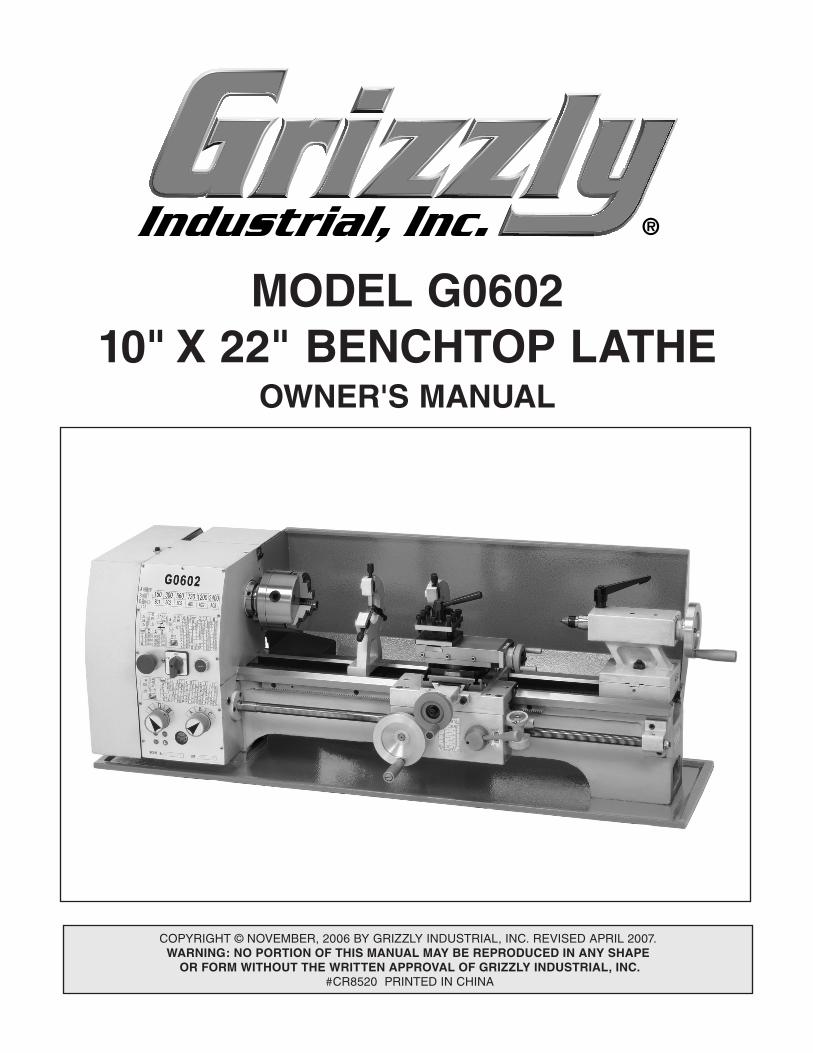
MODEL G0602 10" X 22" BENCHTOP LATHE
OWNER'S MANUAL

�������������������������������������������������������������������������������������������������������������������������������������
������������������������������������������������������������������������������������������������������������������������������������������������������������������
�������������������������������������������������������������������������������������������������������������������������������������������������������������������������������������������������������������������������������������������������������������������������������������������������������������������������������������������������������������������������������������������������������
�������������������������������������������������������������������������������������������������������������������������������������������
������������������������������������������������������������������������������������������������������������������������������������������������������������������������������������������������������������������������������������������������������
�� ������������������������������ �������������������������������������������������������������������� ����������������������������������������������������
�������������������������������������������������������������������������������������������������������������������������������������������������������������������������������������������������������������������������������������������������������������������������������������������������������
G0602 10" X 22" Benchtop Lathe -1-
INTRODUCTION ............................................... 2Foreword ........................................................ 2Contact Info ................................................... 2Machine Data Sheet ...................................... 3Identification ................................................... 5
SECTION 1: SAFETY ....................................... 6Additional Safety Instructions for Lathes ....... 8Glossary of Terms ......................................... 9
SECTION 2: CIRCUIT REQUIREMENTS ...... 10110V Operation ............................................ 10
SECTION 3: SET UP ...................................... 11Unpacking .................................................... 11Inventory ...................................................... 12Site Considerations ...................................... 13Clean Up ...................................................... 13Test Run & Break-In ................................... 14
SECTION 4: OPERATIONS ........................... 15Operation Safety .......................................... 15Power Supply ............................................... 15Mounting Chuck or Faceplate ................... 16Replacing Jaws ............................................ 17Four-Jaw Chuck ........................................... 18Faceplate ..................................................... 19Tailstock ....................................................... 20Drilling with the Tailstock ............................. 20Cutting Shallow Tapers with Tailstock ......... 21Aligning Tailstock ........................................ 21Centers ........................................................ 23Steady Rest ................................................. 24Follow Rest .................................................. 24Compound Rest ........................................... 25
Tool Post ...................................................... 25Manual Feed Handwheels ........................... 26Determining Correct Spindle RPM .............. 27Setting Spindle ............................................ 28RPM ............................................................. 28Setting the Power Feed Rate ...................... 29Inch Threads ................................................ 30Metric Threads ............................................. 31
SECTION 5: ACCESSORIES ......................... 32
SECTION 6: MAINTENANCE ......................... 34Basic Maintenance ...................................... 34General Lubrication ..................................... 34Belt Adjustment or Replacement ................. 35
SECTION 7: SERVICE ................................... 36Troubleshooting ........................................... 36Cross Slide Backlash Adjustment ................ 38Gib Adjustments .......................................... 38Electrical Component Connections .............. 39Wiring Diagram ............................................ 40
SECTION 8: PARTS ....................................... 41Spindle and Drive Belt ................................. 41Apron ........................................................... 43Tool Holder and Compound Rest ................ 44Tailstock ....................................................... 45Bed and Leadscew ...................................... 46Steady Rest and Follow Rest ...................... 47Motor and Electrical ..................................... 48Gearbox Diagram A ..................................... 49Gearbox Diagram B ..................................... 50Cross Feed and Carriage ............................ 52
WARRANTY AND RETURNS ........................ 54
Table of Contents
-2- G0602 10" X 22" Benchtop Lathe
If you have any comments regarding this manual, please write to us at the address below:
Grizzly Industrial, Inc.C/O Technical Documentation Manager
P.O. Box 2069Bellingham, WA 98227-2069Email: [email protected]
We stand behind our machines. If you have any service questions or parts requests, please call or write us at the location listed below.
Grizzly Industrial, Inc.1203 Lycoming Mall Circle
Muncy, PA 17756Phone: (570) 546-9663
Fax: (800) 438-5901E-Mail: [email protected] Site: http://www.grizzly.com
Foreword
INTRODUCTION
Contact Info
We are proud to offer the Model G0602 10" X 22" Benchtop Lathe. This machine is part of a grow-ing Grizzly family of fine metalworking machinery. When used according to the guidelines set forth in this manual, you can expect years of trouble-free, enjoyable operation and proof of Grizzly’s com-mitment to customer satisfaction.
We are pleased to provide this manual with the Model G0602. It was written to guide you through assembly, review safety considerations, and cover general operating procedures. It repre-sents our effort to produce the best documenta-tion possible.
The specifications, drawings, and photographs illustrated in this manual represent the Model G0602 as supplied when the manual was pre-pared. However, owing to Grizzly’s policy of con-tinuous improvement, changes may be made at any time with no obligation on the part of Grizzly. For your convenience, we always keep current Grizzly manuals available on our website at www.grizzly.com. Any updates to your machine will be reflected in these manuals as soon as they are complete. Visit our site often to check for the lat-est updates to this manual!
G0602 10" X 22" Benchtop Lathe -3-
Machine Data Sheet
MODEL G0602 10" X 22" BENCHTOP LATHE
Customer Service #: (570) 546-9663 • To Order Call: (800) 523-4777 • Fax #: (800) 438-5901
MACHINE DATA SHEET
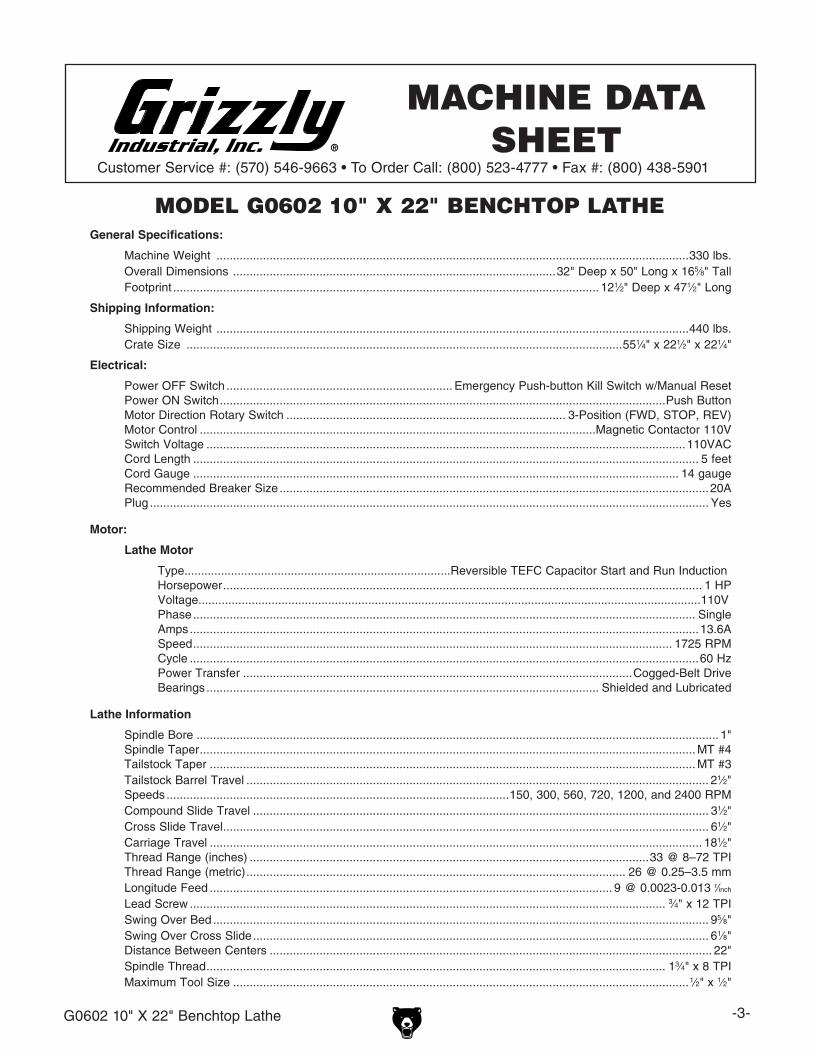
General Specifications:
Machine Weight ..............................................................................................................................................330 lbs. Overall Dimensions .................................................................................................32" Deep x 50" Long x 165⁄8" Tall Footprint ................................................................................................................................ 121⁄2" Deep x 471⁄2" Long
Shipping Information:
Shipping Weight ..............................................................................................................................................440 lbs. Crate Size ...................................................................................................................................551⁄4" x 221⁄2" x 221⁄4"
Electrical:
Power OFF Switch .................................................................... Emergency Push-button Kill Switch w/Manual Reset Power ON Switch ......................................................................................................................................Push Button Motor Direction Rotary Switch .................................................................................... 3-Position (FWD, STOP, REV) Motor Control .......................................................................................................................Magnetic Contactor 110V Switch Voltage ................................................................................................................................................110VAC Cord Length ........................................................................................................................................................ 5 feet Cord Gauge .................................................................................................................................................. 14 gauge Recommended Breaker Size .................................................................................................................................20A Plug ........................................................................................................................................................................ Yes
Motor:
Lathe Motor
Type................................................................................Reversible TEFC Capacitor Start and Run Induction Horsepower ................................................................................................................................................ 1 HP Voltage.......................................................................................................................................................110V Phase ....................................................................................................................................................... Single Amps .........................................................................................................................................................13.6A Speed ................................................................................................................................................ 1725 RPM Cycle .........................................................................................................................................................60 Hz Power Transfer .....................................................................................................................Cogged-Belt Drive Bearings ...................................................................................................................... Shielded and Lubricated
Lathe Information
Spindle Bore ............................................................................................................................................................. 1" Spindle Taper ..................................................................................................................................................... MT #4 Tailstock Taper .................................................................................................................................................. MT #3 Tailstock Barrel Travel ........................................................................................................................................... 21⁄2" Speeds .......................................................................................................150, 300, 560, 720, 1200, and 2400 RPM Compound Slide Travel ......................................................................................................................................... 31⁄2" Cross Slide Travel .................................................................................................................................................. 61⁄2" Carriage Travel .................................................................................................................................................... 181⁄2" Thread Range (inches) ........................................................................................................................33 @ 8–72 TPI Thread Range (metric) .................................................................................................................. 26 @ 0.25–3.5 mm Longitude Feed ......................................................................................................................... 9 @ 0.0023-0.013 r⁄inch
Lead Screw ............................................................................................................................................... 3⁄4" x 12 TPI Swing Over Bed ..................................................................................................................................................... 95⁄8" Swing Over Cross Slide ......................................................................................................................................... 61⁄8" Distance Between Centers ..................................................................................................................................... 22" Spindle Thread .......................................................................................................................................... 13⁄4" x 8 TPI Maximum Tool Size .........................................................................................................................................1⁄2" x 1⁄2"

-4- G0602 10" X 22" Benchtop Lathe
Other Specifications: Country of Origin .................................................................................................................................................China Warranty .............................................................................................................................................................1 Year Serial Number Location .......................................................................................................Data Label on Headstock
Features:
4-Jaw Chuck .......................................................................................................................................................... 61⁄2" 3-Jaw Chuck .............................................................................................................................. w/Int. & Ext. Jaws, 5" Faceplate ................................................................................................................................... w/Int. & Ext. Jaws, 8" Tool Holder .............................................................................................................................4-Way Turret Tool Post Change Gears ...................................................................................................................................................... Steel Dead Center ........................................................................................................................................................ MT#3 Tool Box w/Tool Kit ...................................................................................................................................................... Steady Rest ................................................................................................................................................................. Follow Rest .................................................................................................................................................................. Chip Tray ..................................................................................................................................................................... Back Splash ................................................................................................................................................................. Oil Lubricated Gearbox ................................................................................................................................................
G0602 10" X 22" Benchtop Lathe -5-
Identification
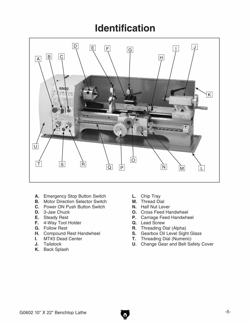
L. Chip TrayM. Thread DialN. Half Nut Lever O. Cross Feed HandwheelP. Carriage Feed HandwheelQ. Lead ScrewR. Threading Dial (Alpha)S. Gearbox Oil Level Sight GlassT. Threading Dial (Numeric)U. Change Gear and Belt Safety Cover
A. Emergency Stop Button SwitchB. Motor Direction Selector SwitchC. Power ON Push Button SwitchD. 3-Jaw ChuckE. Steady RestF. 4-Way Tool HolderG. Follow RestH. Compound Rest HandwheelI. MT#3 Dead CenterJ. TailstockK. Back Splash
U
T S RQ P
O
N M L
K
JI
H
GFED
CBA
-6- G0602 10" X 22" Benchtop Lathe
��� ������� ���� �������� ���������������� ���������� ��������������������� ������ ���� ������ ������������������������
��� ����� ������� ��������� ��� ����������������������������������������������������� �������� ��������������� ���������������������� ����������� ����� ��������� ��� ���������������������������������������������
��� ������ �������� ���������� �������������������������������������������������������������������������������������������������������������
���� ����������������������������������������������������������������������� �������� ������� �������� ��� �����������������
��� ������� ���� ����� ��������������������������������������������������� ��������� ����������� ���������� ������� ���������� ������������ �����������������������
��� ������� ����� �� ������ �������������������� ����� �������������������� ����� ��������� ������������������������������������������������������������������������������������
��������������������������������������������������������������������������
����������������������������������������������������������������������������������������������������������������������������������������������������������������������������������������������������������������������������������������������������������������������������������������������������������������������������������������������������������������������������������������������������������
�����������������������������������������������������������������������������������������������������������������������������������������������������������������
�����������������������������������������������������������������������������������������������������������
����������������������������������������������������������������������������������������������������������
��������������������������������������������������������������������������������������������������������
���������������������������������
�����������������

G0602 10" X 22" Benchtop Lathe -7-
��� ����� ������ �������� ���� ���������� ����������� ���������� ����������� ����������� ����� �������������������������������������������������������������
��� �������������������������������������� ���� ��������� ���� ��������� �� ����� �����������������������������
���� ���������������������������������������� ������� ���������� ���� �������������������������
���� ������ ������ ����� �������� ������������������������������������������������������ �������� �����������������������������������������������������
�������� ���� ���� ��� ������������������������������� ��������������� ��� ���������� ����������� ���������������������������������������������������
�����������������������������������������������������������������������������������������
���� ���������������������������������������������������������������������������������������������������������������� ������ ������� ���������� ����������������������������������������������
���� ������� ����������� ����� ������������� ������� �������������������������������������� ��� ������������������������������������
���� ��������� ���������� ����� ��������������������������������������������������������������������������������������������������������������������������������
���������� ����� ������� ���� ��� ���������� ����� ���������� �����������������������
��������������������������������������������� ���������� ����� ����
�������������������������������������������������������������������������� ����������������������
���� ������ ���� �������� ������������������������������������������������������������������������������������������������������������������������� ��������� ��������������� ������������������ ������������������������������������������
���� ���� ������������ �������������������������������������������������������������� ������������� ��������� �������������������������������������
�������� ���� ������ ���������������� ��������������������������������������������������������������
���� ������� ����������� ���� ������� ���������� �������� ������������������������������� �� �������� ���������� ��������� �������������������������������������������������������
���� ���������������������������������������������������������������
���� ����� ��������� ���� ������������������ ������� ���������������������������������������������������������������������������
���� ������� ����� ������� ����������� ������ ������� ��������������������
������������� ����� ���� ��� ������������� ���� ������������ �������� ��� ������� ��������������������������������������������������� ����� ��� ����� ���� ���� �������� ��� ������������������������������������������������������������������
-8- G0602 10" X 22" Benchtop Lathe
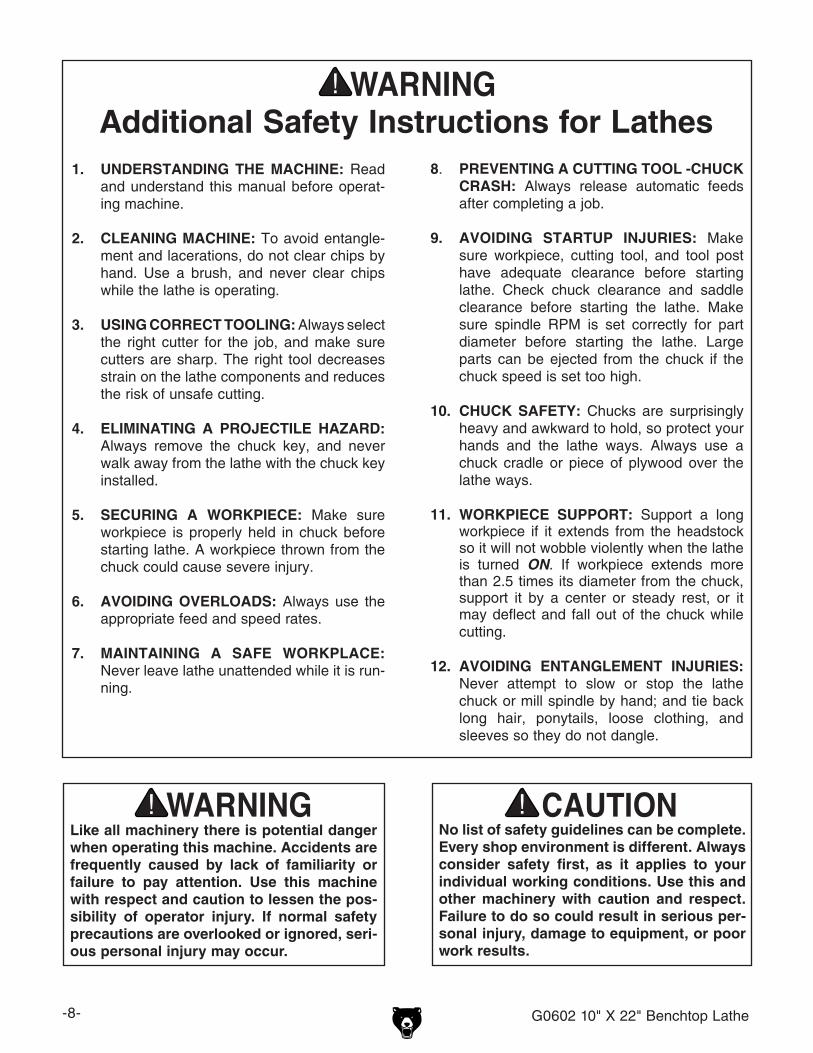
No list of safety guidelines can be complete. Every shop environment is different. Always consider safety first, as it applies to your individual working conditions. Use this and other machinery with caution and respect. Failure to do so could result in serious per-sonal injury, damage to equipment, or poor work results.
Like all machinery there is potential danger when operating this machine. Accidents are frequently caused by lack of familiarity or failure to pay attention. Use this machine with respect and caution to lessen the pos-sibility of operator injury. If normal safety precautions are overlooked or ignored, seri-ous personal injury may occur.
1. UNDERSTANDING THE MACHINE: Read and understand this manual before operat-ing machine.
2. CLEANING MACHINE: To avoid entangle-ment and lacerations, do not clear chips by hand. Use a brush, and never clear chips while the lathe is operating.
3. USING CORRECT TOOLING: Always select the right cutter for the job, and make sure cutters are sharp. The right tool decreases strain on the lathe components and reduces the risk of unsafe cutting.
4. ELIMINATING A PROJECTILE HAZARD: Always remove the chuck key, and never walk away from the lathe with the chuck key installed.
5. SECURING A WORKPIECE: Make sure workpiece is properly held in chuck before starting lathe. A workpiece thrown from the chuck could cause severe injury.
6. AVOIDING OVERLOADS: Always use the appropriate feed and speed rates.
7. MAINTAINING A SAFE WORKPLACE: Never leave lathe unattended while it is run-ning.
8. PREVENTING A CUTTING TOOL -CHUCK CRASH: Always release automatic feeds after completing a job.
9. AVOIDING STARTUP INJURIES: Make sure workpiece, cutting tool, and tool post have adequate clearance before starting lathe. Check chuck clearance and saddle clearance before starting the lathe. Make sure spindle RPM is set correctly for part diameter before starting the lathe. Large parts can be ejected from the chuck if the chuck speed is set too high.
10. CHUCK SAFETY: Chucks are surprisingly heavy and awkward to hold, so protect your hands and the lathe ways. Always use a chuck cradle or piece of plywood over the lathe ways.
11. WORKPIECE SUPPORT: Support a long workpiece if it extends from the headstock so it will not wobble violently when the lathe is turned ON. If workpiece extends more than 2.5 times its diameter from the chuck, support it by a center or steady rest, or it may deflect and fall out of the chuck while cutting.
12. AVOIDING ENTANGLEMENT INJURIES: Never attempt to slow or stop the lathe chuck or mill spindle by hand; and tie back long hair, ponytails, loose clothing, and sleeves so they do not dangle.
Additional Safety Instructions for Lathes
G0602 10" X 22" Benchtop Lathe -9-
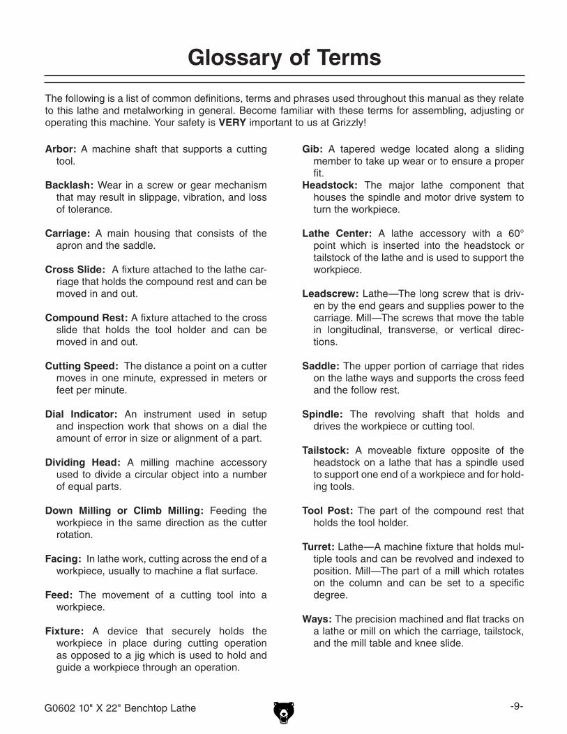
The following is a list of common definitions, terms and phrases used throughout this manual as they relate to this lathe and metalworking in general. Become familiar with these terms for assembling, adjusting or operating this machine. Your safety is VERY important to us at Grizzly!
Arbor: A machine shaft that supports a cutting tool.
Backlash: Wear in a screw or gear mechanism that may result in slippage, vibration, and loss of tolerance.
Carriage: A main housing that consists of the apron and the saddle.
Cross Slide: A fixture attached to the lathe car-riage that holds the compound rest and can be moved in and out.
Compound Rest: A fixture attached to the cross slide that holds the tool holder and can be moved in and out.
Cutting Speed: The distance a point on a cutter moves in one minute, expressed in meters or feet per minute.
Dial Indicator: An instrument used in setup and inspection work that shows on a dial the amount of error in size or alignment of a part.
Dividing Head: A milling machine accessory used to divide a circular object into a number of equal parts.
Down Milling or Climb Milling: Feeding the workpiece in the same direction as the cutter rotation.
Facing: In lathe work, cutting across the end of a workpiece, usually to machine a flat surface.
Feed: The movement of a cutting tool into a workpiece.
Fixture: A device that securely holds the workpiece in place during cutting operation as opposed to a jig which is used to hold and guide a workpiece through an operation.
Gib: A tapered wedge located along a sliding member to take up wear or to ensure a proper fit.
Headstock: The major lathe component that houses the spindle and motor drive system to turn the workpiece.
Lathe Center: A lathe accessory with a 60° point which is inserted into the headstock or tailstock of the lathe and is used to support the workpiece.
Leadscrew: Lathe—The long screw that is driv-en by the end gears and supplies power to the carriage. Mill—The screws that move the table in longitudinal, transverse, or vertical direc-tions.
Saddle: The upper portion of carriage that rides on the lathe ways and supports the cross feed and the follow rest.
Spindle: The revolving shaft that holds and drives the workpiece or cutting tool.
Tailstock: A moveable fixture opposite of the headstock on a lathe that has a spindle used to support one end of a workpiece and for hold-ing tools.
Tool Post: The part of the compound rest that holds the tool holder.
Turret: Lathe—A machine fixture that holds mul-tiple tools and can be revolved and indexed to position. Mill—The part of a mill which rotates on the column and can be set to a specific degree.
Ways: The precision machined and flat tracks on a lathe or mill on which the carriage, tailstock, and the mill table and knee slide.
Glossary of Terms
-10- G0602 10" X 22" Benchtop Lathe
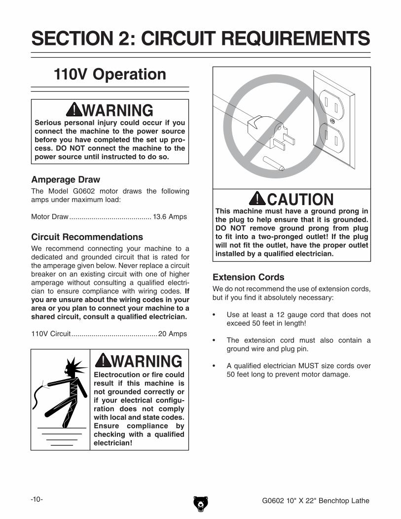
Serious personal injury could occur if you connect the machine to the power source before you have completed the set up pro-cess. DO NOT connect the machine to the power source until instructed to do so.
110V Operation
Amperage DrawThe Model G0602 motor draws the following amps under maximum load:
Motor Draw ......................................... 13.6 Amps
Circuit RecommendationsWe recommend connecting your machine to a dedicated and grounded circuit that is rated for the amperage given below. Never replace a circuit breaker on an existing circuit with one of higher amperage without consulting a qualified electri-cian to ensure compliance with wiring codes. If you are unsure about the wiring codes in your area or you plan to connect your machine to a shared circuit, consult a qualified electrician.
110V Circuit ...........................................20 Amps
This machine must have a ground prong in the plug to help ensure that it is grounded. DO NOT remove ground prong from plug to fit into a two-pronged outlet! If the plug will not fit the outlet, have the proper outlet installed by a qualified electrician.
Extension CordsWe do not recommend the use of extension cords, but if you find it absolutely necessary:
• Use at least a 12 gauge cord that does not exceed 50 feet in length!
• The extension cord must also contain a ground wire and plug pin.
• A qualified electrician MUST size cords over 50 feet long to prevent motor damage.
SECTION 2: CIRCUIT REQUIREMENTS
Electrocution or fire could result if this machine is not grounded correctly or if your electrical configu-ration does not comply with local and state codes. Ensure compliance by checking with a qualified electrician!
G0602 10" X 22" Benchtop Lathe -11-
SECTION 3: SET UP
The Model G0602 weighs approximately 440 lbs. DO NOT attempt to lift and position this machine without using power lifting equipment. Inspect all lifting equipment and make sure that all is in perfect work-ing order and is rated for the load before attempting to lift and move this lathe. Ignoring this warning may lead to serious personal injury or death.
The Model G0602 was carefully packed when it left our warehouse. If you discover the machine is damaged after you have signed for delivery, please immediately call Customer Service at (570) 546-9663 for advice.
Save the containers and all packing materials for possible inspection by the carrier or its agent. Otherwise, filing a freight claim can be difficult.
When you are completely satisfied with the condi-tion of your shipment, inventory the contents.
Unpacking
-12- G0602 10" X 22" Benchtop Lathe
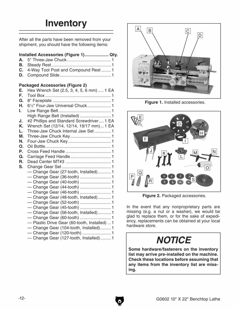
After all the parts have been removed from your shipment, you should have the following items:
Installed Accessories (Figure 1) .................... Qty.A. 5" Three-Jaw Chuck ..................................... 1B. Steady Rest .................................................. 1C. 4-Way Tool Post and Compound Rest ........ 1D. Compound Slide ........................................... 1
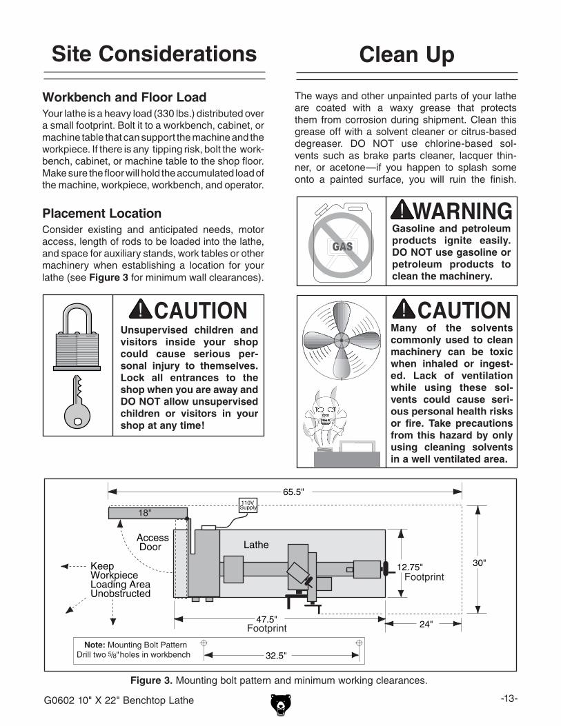
Packaged Accessories (Figure 2)E. Hex Wrench Set (2.5, 3, 4, 5, 6 mm) ..... 1 EAF. Tool Box ....................................................... 1G. 8" Faceplate ................................................. 1H. 61⁄2" Four-Jaw Universal Chuck .................... 1I. Low Range Belt ............................................ 1 High Range Belt (Installed) .......................... 1J. #2 Phillips and Standard Screwdriver .... 1 EAK. Wrench Set (12/14, 12/14, 19/17 mm) ... 1 EAL. Three-Jaw Chuck Internal Jaw Set .............. 1M. Three-Jaw Chuck Key .................................. 1N. Four-Jaw Chuck Key .................................... 1O. Oil Bottle ....................................................... 1 P. Cross Feed Handle ...................................... 1Q. Carriage Feed Handle .................................. 1R. Dead Center MT#3 ...................................... 1S. Change Gear Set ......................................... 1 — Change Gear (27-tooth, Installed) ........... 1 — Change Gear (36-tooth) .......................... 1 — Change Gear (40-tooth) .......................... 1 — Change Gear (44-tooth) .......................... 1 — Change Gear (46-tooth) .......................... 1 — Change Gear (48-tooth, Installed) ........... 1 — Change Gear (52-tooth) .......................... 1 — Change Gear (45-tooth) .......................... 1 — Change Gear (56-tooth, Installed) ........... 1 — Change Gear (60-tooth) .......................... 1 — Plastic Drive Gear (60-tooth, Installed) ... 1 — Change Gear (104-tooth, Installed) ......... 1 — Change Gear (120-tooth) ........................ 1 — Change Gear (127-tooth, Installed) ......... 1
Figure 1. Installed accessories.
D
A B C
Inventory
In the event that any nonproprietary parts are missing (e.g. a nut or a washer), we would be glad to replace them, or for the sake of expedi-ency, replacements can be obtained at your local hardware store.
NOTICESome hardware/fasteners on the inventory list may arrive pre-installed on the machine. Check these locations before assuming that any items from the inventory list are miss-ing.
Figure 2. Packaged accessories.
F
G
H
I
JK
LM N
O
PR S
E
Q
G0602 10" X 22" Benchtop Lathe -13-
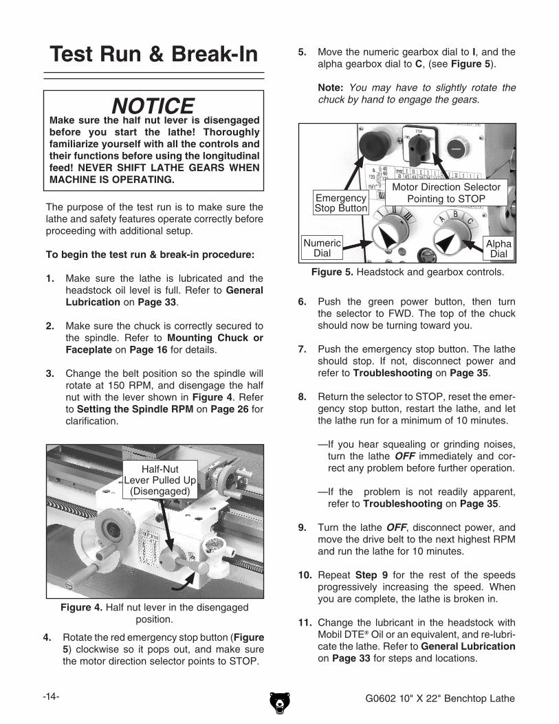
Workbench and Floor LoadYour lathe is a heavy load (330 lbs.) distributed over a small footprint. Bolt it to a workbench, cabinet, or machine table that can support the machine and the workpiece. If there is any tipping risk, bolt the work-bench, cabinet, or machine table to the shop floor.Make sure the floor will hold the accumulated load of the machine, workpiece, workbench, and operator.
Placement LocationConsider existing and anticipated needs, motor access, length of rods to be loaded into the lathe, and space for auxiliary stands, work tables or other machinery when establishing a location for your lathe (see Figure 3 for minimum wall clearances).
The ways and other unpainted parts of your lathe are coated with a waxy grease that protects them from corrosion during shipment. Clean this grease off with a solvent cleaner or citrus-based degreaser. DO NOT use chlorine-based sol-vents such as brake parts cleaner, lacquer thin-ner, or acetone—if you happen to splash some onto a painted surface, you will ruin the finish.
������ ���
�����
�����
���
����������������������������������������
����������� �����
�����������
���������
���������
���
��������������������������������
�������������������������������������
Figure 3. Mounting bolt pattern and minimum working clearances.
Unsupervised children and visitors inside your shop could cause serious per-sonal injury to themselves. Lock all entrances to the shop when you are away and DO NOT allow unsupervised children or visitors in your shop at any time!
Site Considerations Clean Up
Gasoline and petroleum products ignite easily. DO NOT use gasoline or petroleum products to clean the machinery.
Many of the solvents commonly used to clean machinery can be toxic when inhaled or ingest-ed. Lack of ventilation while using these sol-vents could cause seri-ous personal health risks or fire. Take precautions from this hazard by only using cleaning solvents in a well ventilated area.
-14- G0602 10" X 22" Benchtop Lathe
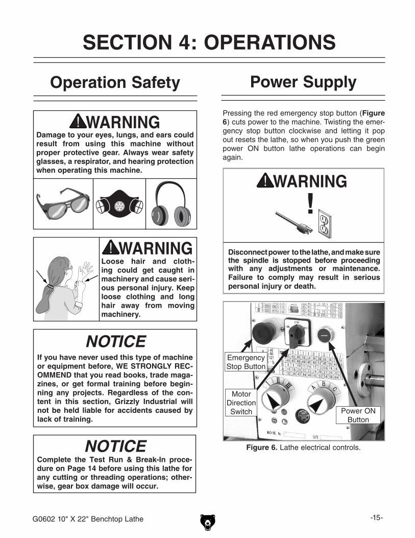
5. Move the numeric gearbox dial to I, and the alpha gearbox dial to C, (see Figure 5).
Note: You may have to slightly rotate the
chuck by hand to engage the gears.
6. Push the green power button, then turn the selector to FWD. The top of the chuck should now be turning toward you.
7. Push the emergency stop button. The lathe should stop. If not, disconnect power and refer to Troubleshooting on Page 35.
8. Return the selector to STOP, reset the emer-gency stop button, restart the lathe, and let the lathe run for a minimum of 10 minutes.
—If you hear squealing or grinding noises, turn the lathe OFF immediately and cor-rect any problem before further operation.
—If the problem is not readily apparent, refer to Troubleshooting on Page 35.
9. Turn the lathe OFF, disconnect power, and move the drive belt to the next highest RPM and run the lathe for 10 minutes.
10. Repeat Step 9 for the rest of the speeds progressively increasing the speed. When you are complete, the lathe is broken in.
11. Change the lubricant in the headstock with Mobil DTE® Oil or an equivalent, and re-lubri-cate the lathe. Refer to General Lubrication on Page 33 for steps and locations.
Test Run & Break-In
The purpose of the test run is to make sure the lathe and safety features operate correctly before proceeding with additional setup.
To begin the test run & break-in procedure:
1. Make sure the lathe is lubricated and the headstock oil level is full. Refer to General Lubrication on Page 33.
2. Make sure the chuck is correctly secured to the spindle. Refer to Mounting Chuck or Faceplate on Page 16 for details.
3. Change the belt position so the spindle will rotate at 150 RPM, and disengage the half nut with the lever shown in Figure 4. Refer to Setting the Spindle RPM on Page 26 for clarification.
Motor Direction SelectorPointing to STOPEmergency
Stop Button
Figure 5. Headstock and gearbox controls.
Make sure the half nut lever is disengaged before you start the lathe! Thoroughly familiarize yourself with all the controls and their functions before using the longitudinal feed! NEVER SHIFT LATHE GEARS WHEN MACHINE IS OPERATING.
NOTICE
Figure 4. Half nut lever in the disengaged position.
Half-NutLever Pulled Up
(Disengaged)
4. Rotate the red emergency stop button (Figure 5) clockwise so it pops out, and make sure the motor direction selector points to STOP.
Numeric Dial
Alpha Dial
G0602 10" X 22" Benchtop Lathe -15-
Pressing the red emergency stop button (Figure 6) cuts power to the machine. Twisting the emer-gency stop button clockwise and letting it pop out resets the lathe, so when you push the green power ON button lathe operations can begin again.
Disconnect power to the lathe, and make sure the spindle is stopped before proceeding with any adjustments or maintenance. Failure to comply may result in serious personal injury or death.
Figure 6. Lathe electrical controls.
EmergencyStop Button
Power ONButton
MotorDirectionSwitch
Operation Safety
SECTION 4: OPERATIONS
Power Supply
Damage to your eyes, lungs, and ears could result from using this machine without proper protective gear. Always wear safety glasses, a respirator, and hearing protection when operating this machine.
Loose hair and cloth-ing could get caught in machinery and cause seri-ous personal injury. Keep loose clothing and long hair away from moving machinery.
NOTICEIf you have never used this type of machine or equipment before, WE STRONGLY REC-OMMEND that you read books, trade maga-zines, or get formal training before begin-ning any projects. Regardless of the con-tent in this section, Grizzly Industrial will not be held liable for accidents caused by lack of training.
Complete the Test Run & Break-In proce-dure on Page 14 before using this lathe for any cutting or threading operations; other-wise, gear box damage will occur.
NOTICE
-16- G0602 10" X 22" Benchtop Lathe
Mounting Chuck or Faceplate
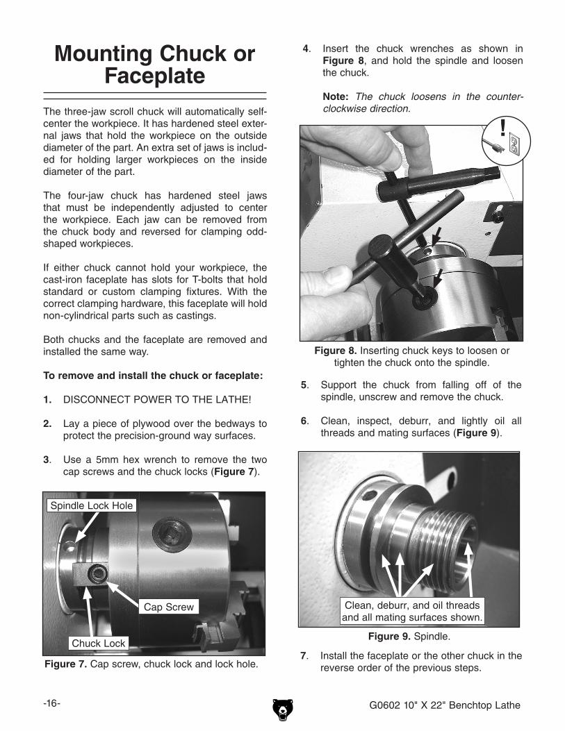
4. Insert the chuck wrenches as shown in Figure 8, and hold the spindle and loosen the chuck.
Note: The chuck loosens in the counter-clockwise direction. The three-jaw scroll chuck will automatically self-
center the workpiece. It has hardened steel exter-nal jaws that hold the workpiece on the outside diameter of the part. An extra set of jaws is includ-ed for holding larger workpieces on the inside diameter of the part.
The four-jaw chuck has hardened steel jaws that must be independently adjusted to center the workpiece. Each jaw can be removed from the chuck body and reversed for clamping odd-shaped workpieces.
If either chuck cannot hold your workpiece, the cast-iron faceplate has slots for T-bolts that hold standard or custom clamping fixtures. With the correct clamping hardware, this faceplate will hold non-cylindrical parts such as castings.
Both chucks and the faceplate are removed and installed the same way.
To remove and install the chuck or faceplate:
1. DISCONNECT POWER TO THE LATHE!
2. Lay a piece of plywood over the bedways to protect the precision-ground way surfaces.
3. Use a 5mm hex wrench to remove the two cap screws and the chuck locks (Figure 7).
Figure 8. Inserting chuck keys to loosen or tighten the chuck onto the spindle.
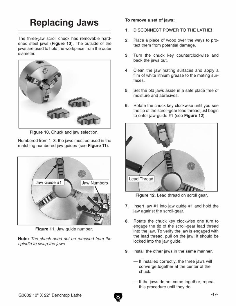
Figure 9. Spindle.
Figure 7. Cap screw, chuck lock and lock hole.
Chuck Lock
Cap Screw
Spindle Lock Hole
5. Support the chuck from falling off of the spindle, unscrew and remove the chuck.
6. Clean, inspect, deburr, and lightly oil all threads and mating surfaces (Figure 9).
7. Install the faceplate or the other chuck in the reverse order of the previous steps.
Clean, deburr, and oil threads and all mating surfaces shown.
G0602 10" X 22" Benchtop Lathe -17-
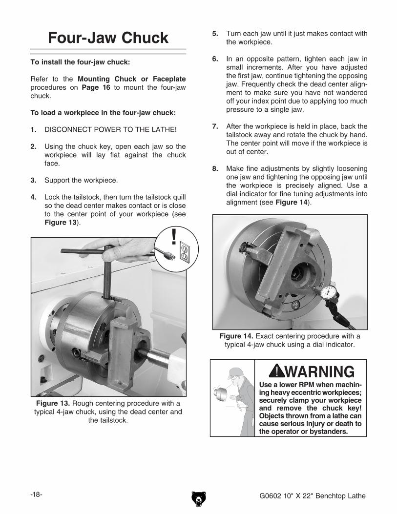
The three-jaw scroll chuck has removable hard-ened steel jaws (Figure 10). The outside of the jaws are used to hold the workpiece from the outer diameter.
Figure 10. Chuck and jaw selection.
To remove a set of jaws:
1. DISCONNECT POWER TO THE LATHE!
2. Place a piece of wood over the ways to pro-tect them from potential damage.
3. Turn the chuck key counterclockwise and back the jaws out.
4. Clean the jaw mating surfaces and apply a film of white lithium grease to the mating sur-faces.
5. Set the old jaws aside in a safe place free of moisture and abrasives.
6. Rotate the chuck key clockwise until you see the tip of the scroll-gear lead thread just begin to enter jaw guide #1 (see Figure 12).
7. Insert jaw #1 into jaw guide #1 and hold the jaw against the scroll-gear.
8. Rotate the chuck key clockwise one turn to engage the tip of the scroll-gear lead thread into the jaw. To verify the jaw is engaged with the lead thread, pull on the jaw; it should be locked into the jaw guide.
9. Install the other jaws in the same manner.
— If installed correctly, the three jaws will converge together at the center of the chuck.
— If the jaws do not come together, repeat this procedure until they do.
Figure 12. Lead thread on scroll gear.
Lead Thread
Numbered from 1–3, the jaws must be used in the matching numbered jaw guides (see Figure 11).
Figure 11. Jaw guide number.
Jaw Guide #1 Jaw Numbers
Note: The chuck need not be removed from the spindle to swap the jaws.
Replacing Jaws
-18- G0602 10" X 22" Benchtop Lathe
5. Turn each jaw until it just makes contact with the workpiece.
6. In an opposite pattern, tighten each jaw in small increments. After you have adjusted the first jaw, continue tightening the opposing jaw. Frequently check the dead center align-ment to make sure you have not wandered off your index point due to applying too much pressure to a single jaw.
7. After the workpiece is held in place, back the tailstock away and rotate the chuck by hand. The center point will move if the workpiece is out of center.
8. Make fine adjustments by slightly loosening one jaw and tightening the opposing jaw until the workpiece is precisely aligned. Use a dial indicator for fine tuning adjustments into alignment (see Figure 14).
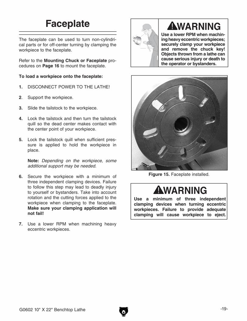
Figure 13. Rough centering procedure with a typical 4-jaw chuck, using the dead center and
the tailstock.
Figure 14. Exact centering procedure with a typical 4-jaw chuck using a dial indicator.
To install the four-jaw chuck:
Refer to the Mounting Chuck or Faceplate procedures on Page 16 to mount the four-jaw chuck.
To load a workpiece in the four-jaw chuck:
1. DISCONNECT POWER TO THE LATHE!
2. Using the chuck key, open each jaw so the workpiece will lay flat against the chuck face.
3. Support the workpiece.
4. Lock the tailstock, then turn the tailstock quill so the dead center makes contact or is close to the center point of your workpiece (see Figure 13).
Four-Jaw Chuck
Use a lower RPM when machin-ing heavy eccentric workpieces; securely clamp your workpiece and remove the chuck key! Objects thrown from a lathe can cause serious injury or death to the operator or bystanders.
G0602 10" X 22" Benchtop Lathe -19-
The faceplate can be used to turn non-cylindri-cal parts or for off-center turning by clamping the workpiece to the faceplate.
Refer to the Mounting Chuck or Faceplate pro-cedures on Page 16 to mount the faceplate.
To load a workpiece onto the faceplate:
1. DISCONNECT POWER TO THE LATHE!
2. Support the workpiece.
3. Slide the tailstock to the workpiece.
4. Lock the tailstock and then turn the tailstock quill so the dead center makes contact with the center point of your workpiece.
5. Lock the tailstock quill when sufficient pres-sure is applied to hold the workpiece in place.
Note: Depending on the workpiece, some additional support may be needed.
6. Secure the workpiece with a minimum of three independent clamping devices. Failure to follow this step may lead to deadly injury to yourself or bystanders. Take into account rotation and the cutting forces applied to the workpiece when clamping to the faceplate. Make sure your clamping application will not fail!
7. Use a lower RPM when machining heavy eccentric workpieces.
Figure 15. Faceplate installed.
Use a minimum of three independent clamping devices when turning eccentric workpieces. Failure to provide adequate clamping will cause workpiece to eject.
FaceplateUse a lower RPM when machin-ing heavy eccentric workpieces; securely clamp your workpiece and remove the chuck key! Objects thrown from a lathe can cause serious injury or death to the operator or bystanders.
-20- G0602 10" X 22" Benchtop Lathe
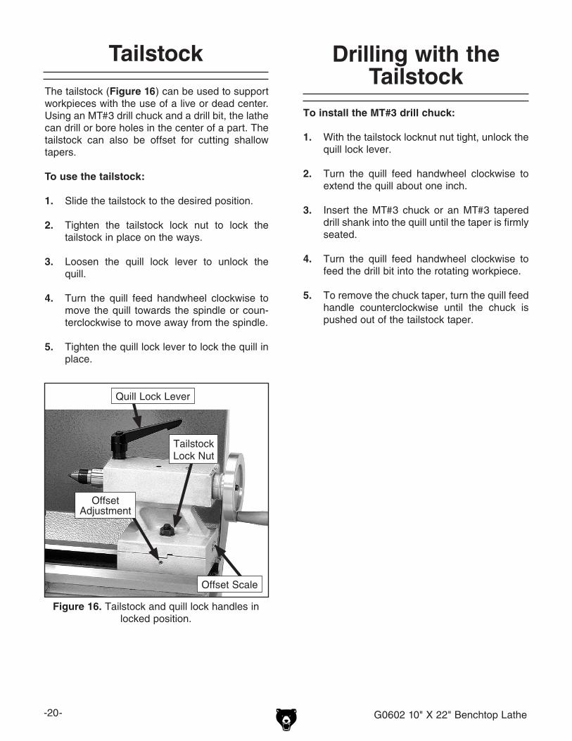
The tailstock (Figure 16) can be used to support workpieces with the use of a live or dead center. Using an MT#3 drill chuck and a drill bit, the lathe can drill or bore holes in the center of a part. The tailstock can also be offset for cutting shallow tapers.
To use the tailstock:
1. Slide the tailstock to the desired position.
2. Tighten the tailstock lock nut to lock the tailstock in place on the ways.
3. Loosen the quill lock lever to unlock the quill.
4. Turn the quill feed handwheel clockwise to move the quill towards the spindle or coun-terclockwise to move away from the spindle.
5. Tighten the quill lock lever to lock the quill in place.
Figure 16. Tailstock and quill lock handles in locked position.
Tailstock Lock Nut
Quill Lock Lever
To install the MT#3 drill chuck:
1. With the tailstock locknut nut tight, unlock the quill lock lever.
2. Turn the quill feed handwheel clockwise to extend the quill about one inch.
3. Insert the MT#3 chuck or an MT#3 tapered drill shank into the quill until the taper is firmly seated.
4. Turn the quill feed handwheel clockwise to feed the drill bit into the rotating workpiece.
5. To remove the chuck taper, turn the quill feed handle counterclockwise until the chuck is pushed out of the tailstock taper.
OffsetAdjustment
Tailstock Drilling with the Tailstock
Offset Scale
G0602 10" X 22" Benchtop Lathe -21-
To setup the tailstock to cut tapers:
1. Loosen the tailstock lock nut.
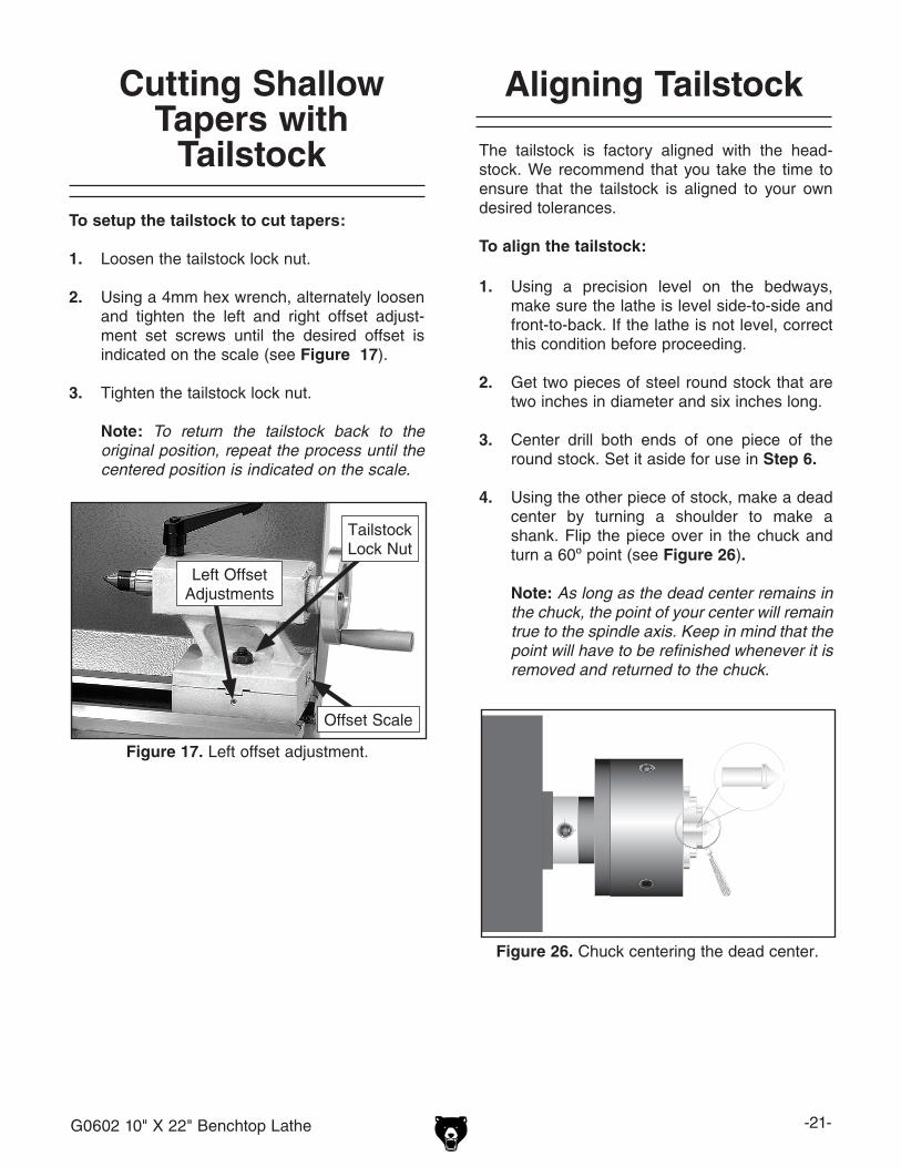
2. Using a 4mm hex wrench, alternately loosen and tighten the left and right offset adjust-ment set screws until the desired offset is indicated on the scale (see Figure 17).
3. Tighten the tailstock lock nut.
Note: To return the tailstock back to the original position, repeat the process until the centered position is indicated on the scale.
The tailstock is factory aligned with the head-stock. We recommend that you take the time to ensure that the tailstock is aligned to your own desired tolerances.
To align the tailstock:
1. Using a precision level on the bedways, make sure the lathe is level side-to-side and front-to-back. If the lathe is not level, correct this condition before proceeding.
2. Get two pieces of steel round stock that are two inches in diameter and six inches long.
3. Center drill both ends of one piece of the round stock. Set it aside for use in Step 6.
4. Using the other piece of stock, make a dead center by turning a shoulder to make a shank. Flip the piece over in the chuck and turn a 60º point (see Figure 26).
Note: As long as the dead center remains in
the chuck, the point of your center will remain true to the spindle axis. Keep in mind that the point will have to be refinished whenever it is removed and returned to the chuck.
Figure 26. Chuck centering the dead center.
Aligning Tailstock Cutting Shallow Tapers with
Tailstock
Figure 17. Left offset adjustment.
Left OffsetAdjustments
Offset Scale
Tailstock Lock Nut
-22- G0602 10" X 22" Benchtop Lathe
5. Place the live center in the tailstock.
6. Attach a lathe dog to the bar stock and mount it between centers.
7. Turn approximately 0.010" off the diameter.
8. Measure the stock with a micrometer.
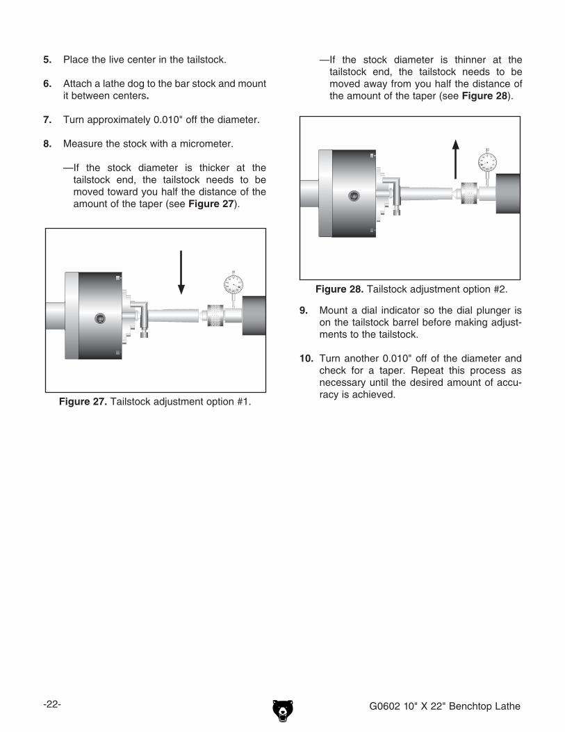
—If the stock diameter is thicker at the tailstock end, the tailstock needs to be moved toward you half the distance of the amount of the taper (see Figure 27).
Figure 27. Tailstock adjustment option #1.
—If the stock diameter is thinner at the
tailstock end, the tailstock needs to be moved away from you half the distance of the amount of the taper (see Figure 28).
Figure 28. Tailstock adjustment option #2.
9. Mount a dial indicator so the dial plunger is on the tailstock barrel before making adjust-ments to the tailstock.
10. Turn another 0.010" off of the diameter and check for a taper. Repeat this process as necessary until the desired amount of accu-racy is achieved.
G0602 10" X 22" Benchtop Lathe -23-
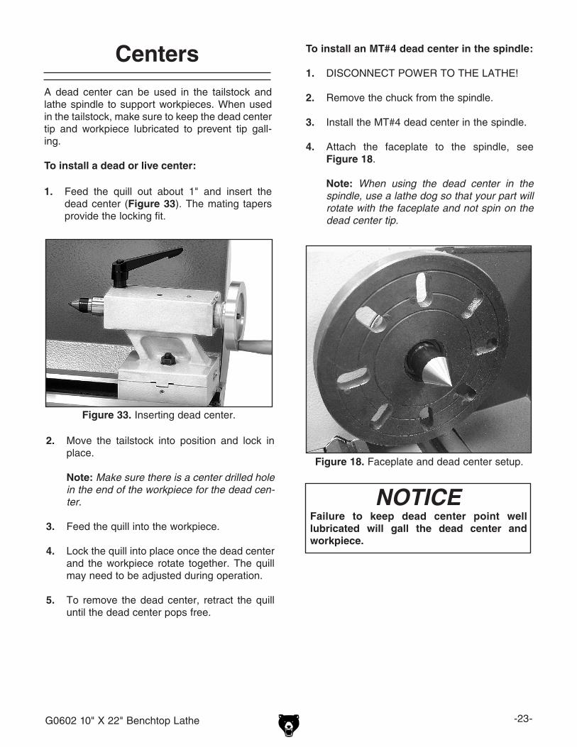
A dead center can be used in the tailstock and lathe spindle to support workpieces. When used in the tailstock, make sure to keep the dead center tip and workpiece lubricated to prevent tip gall-ing.
To install a dead or live center:
1. Feed the quill out about 1" and insert the dead center (Figure 33). The mating tapers provide the locking fit.
Figure 18. Faceplate and dead center setup.
NOTICEFailure to keep dead center point well lubricated will gall the dead center and workpiece.
Centers To install an MT#4 dead center in the spindle:
1. DISCONNECT POWER TO THE LATHE!
2. Remove the chuck from the spindle.
3. Install the MT#4 dead center in the spindle.
4. Attach the faceplate to the spindle, see Figure 18.
Note: When using the dead center in the spindle, use a lathe dog so that your part will rotate with the faceplate and not spin on the dead center tip.
Figure 33. Inserting dead center.
2. Move the tailstock into position and lock in place.
Note: Make sure there is a center drilled hole in the end of the workpiece for the dead cen-ter.
3. Feed the quill into the workpiece.
4. Lock the quill into place once the dead center and the workpiece rotate together. The quill may need to be adjusted during operation.
5. To remove the dead center, retract the quill until the dead center pops free.

-24- G0602 10" X 22" Benchtop Lathe
The follow rest in Figure 37 is mounted on the front of the carriage directly above the ways and follows the movement of the tool. The fol-low rest requires only two fingers, as the cutting tool acts as the third. The follow rest is used on long, slender parts to prevent flexing of the workpiece from the pressure of the cutting tool.
The sliding fingers are set similar to those of the steady rest—free of play but not bind-ing. Always lubricate during operation. After prolonged use, the fingers will need to be milled or filed to clean up the contact surface.
The steady rest serves as a support for long shafts. The steady rest can be placed anywhere along the length of the ways.
To use the steady rest:
1. Carefully place the steady rest on the lathe bedways.
2. Loosen the finger lock nuts so the finger position can be adjusted (see Figure 35).
3. Loosen the steady rest lock nut (see Figure 35), and position the steady rest where desired.
4. Tighten the steady rest lock nut.
5. Clamp the workpiece with the chuck and posi-tion the tailstock to support the workpiece.
6. Turn the adjustment knobs so the fingers are snug against the workpiece, and then tighten the finger lock nuts.
7. Lubricate the finger tips with an anti-seize lubricant during operation.
8. After prolonged use, the fingers will show wear. Either mill or file the tips for a new con-tact surface.
Figure 35. Steady rest.
Finger
Adjustment Knob
Steady Rest
Lock NutFinger
Lock Nut
Figure 37. Follow rest.
Adjustment Knob
FingerCarriage
Cap Screw
FingerLock Nut
Steady Rest Follow Rest
G0602 10" X 22" Benchtop Lathe -25-
The compound rest is used to cut tapers on parts or to set the proper infeed angle when threading. It may also be used to cut specific lengths longitu-dinally, when set parallel to the spindle axis.
To set the angular position:
1. Loosen the hex nuts on each side of the com-pound rest (see Figure 38).
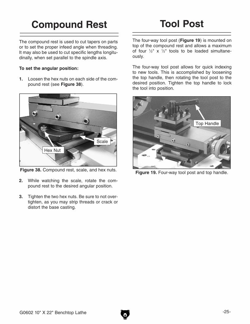
The four-way tool post (Figure 19) is mounted on top of the compound rest and allows a maximum of four 1⁄2" x 1⁄2" tools to be loaded simultane-ously.
The four-way tool post allows for quick indexing to new tools. This is accomplished by loosening the top handle, then rotating the tool post to the desired position. Tighten the top handle to lock the tool into position.
Tool PostCompound Rest
Figure 38. Compound rest, scale, and hex nuts.
Scale
Hex Nut
2. While watching the scale, rotate the com-pound rest to the desired angular position.
3. Tighten the two hex nuts. Be sure to not over-tighten, as you may strip threads or crack or distort the base casting.
Figure 19. Four-way tool post and top handle.
Top Handle
-26- G0602 10" X 22" Benchtop Lathe
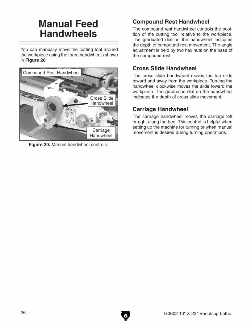
You can manually move the cutting tool around the workpiece using the three handwheels shown in Figure 20.
S
Figure 20. Manual handwheel controls.
Cross Slide Handwheel
CarriageHandwheel
Manual Feed Handwheels
Compound Rest Handwheel
Compound Rest HandwheelThe compound rest handwheel controls the posi-tion of the cutting tool relative to the workpiece. The graduated dial on the handwheel indicates the depth of compound rest movement. The angle adjustment is held by two hex nuts on the base of the compound rest.
Cross Slide HandwheelThe cross slide handwheel moves the top slide toward and away from the workpiece. Turning the handwheel clockwise moves the slide toward the workpiece. The graduated dial on the handwheel indicates the depth of cross slide movement.
Carriage HandwheelThe carriage handwheel moves the carriage left or right along the bed. This control is helpful when setting up the machine for turning or when manual movement is desired during turning operations.
G0602 10" X 22" Benchtop Lathe -27-
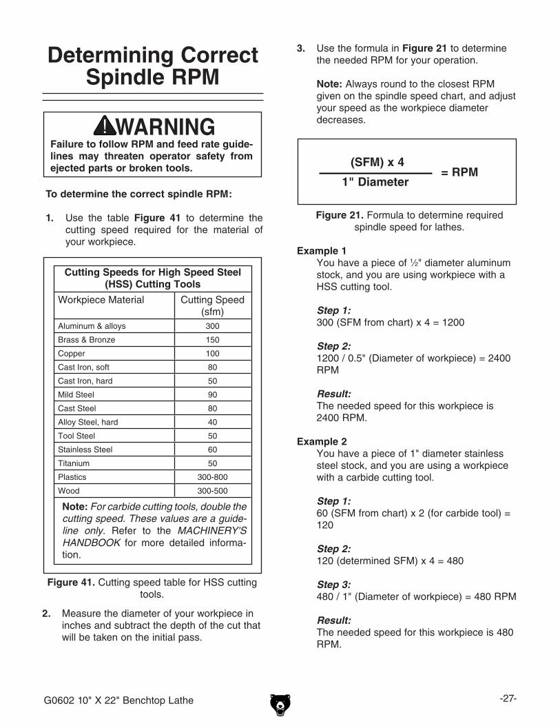
Cutting Speeds for High Speed Steel (HSS) Cutting Tools
Workpiece Material Cutting Speed (sfm)
Aluminum & alloys 300
Brass & Bronze 150
Copper 100
Cast Iron, soft 80
Cast Iron, hard 50
Mild Steel 90
Cast Steel 80
Alloy Steel, hard 40
Tool Steel 50
Stainless Steel 60
Titanium 50
Plastics 300-800
Wood 300-500
Figure 41. Cutting speed table for HSS cutting tools.
Note: For carbide cutting tools, double the cutting speed. These values are a guide-line only. Refer to the MACHINERY'S HANDBOOK for more detailed informa-tion.
To determine the correct spindle RPM:
1. Use the table Figure 41 to determine the cutting speed required for the material of your workpiece.
Determining Correct Spindle RPM
3. Use the formula in Figure 21 to determine the needed RPM for your operation.
Note: Always round to the closest RPM given on the spindle speed chart, and adjust your speed as the workpiece diameter decreases.
Example 1 You have a piece of 1⁄2" diameter aluminum
stock, and you are using workpiece with a HSS cutting tool.
Step 1: 300 (SFM from chart) x 4 = 1200
Step 2: 1200 / 0.5" (Diameter of workpiece) = 2400
RPM
Result: The needed speed for this workpiece is
2400 RPM.
Example 2 You have a piece of 1" diameter stainless
steel stock, and you are using a workpiece with a carbide cutting tool.
Step 1: 60 (SFM from chart) x 2 (for carbide tool) =
120
Step 2: 120 (determined SFM) x 4 = 480
Step 3: 480 / 1" (Diameter of workpiece) = 480 RPM
Result: The needed speed for this workpiece is 480
RPM.
Failure to follow RPM and feed rate guide-lines may threaten operator safety from ejected parts or broken tools.
2. Measure the diameter of your workpiece in inches and subtract the depth of the cut that will be taken on the initial pass.
Figure 21. Formula to determine required spindle speed for lathes.
= RPM(SFM) x 4
1" Diameter
-28- G0602 10" X 22" Benchtop Lathe
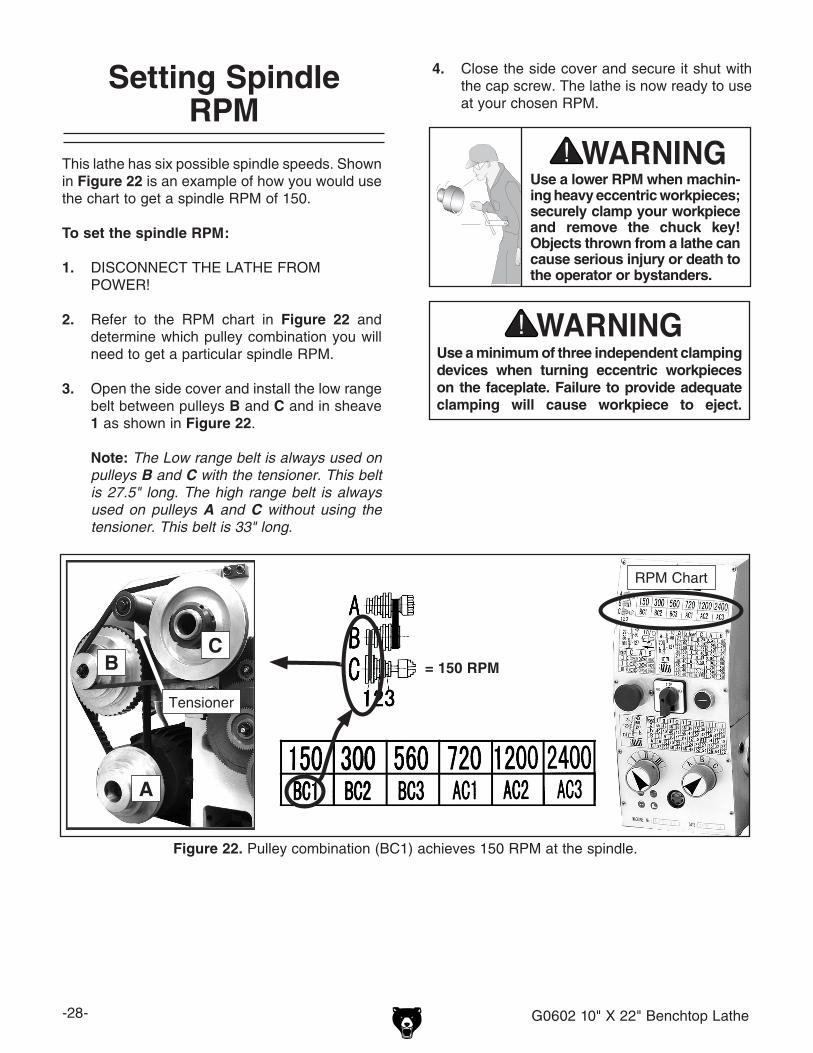
Figure 22. Pulley combination (BC1) achieves 150 RPM at the spindle.
This lathe has six possible spindle speeds. Shown in Figure 22 is an example of how you would use the chart to get a spindle RPM of 150.
To set the spindle RPM:
1. DISCONNECT THE LATHE FROM POWER!
2. Refer to the RPM chart in Figure 22 and determine which pulley combination you will need to get a particular spindle RPM.
3. Open the side cover and install the low range belt between pulleys B and C and in sheave 1 as shown in Figure 22.
Note: The Low range belt is always used on pulleys B and C with the tensioner. This belt is 27.5" long. The high range belt is always used on pulleys A and C without using the tensioner. This belt is 33" long.
4. Close the side cover and secure it shut with the cap screw. The lathe is now ready to use at your chosen RPM.
Tensioner
Use a minimum of three independent clamping devices when turning eccentric workpieces on the faceplate. Failure to provide adequate clamping will cause workpiece to eject.
= 150 RPM
RPM Chart
CB
A
Use a lower RPM when machin-ing heavy eccentric workpieces; securely clamp your workpiece and remove the chuck key! Objects thrown from a lathe can cause serious injury or death to the operator or bystanders.
Setting Spindle RPM
G0602 10" X 22" Benchtop Lathe -29-
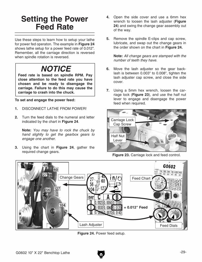
Use these steps to learn how to setup your lathe for power fed operaton. The example in Figure 24 shows lathe setup for a power feed rate of 0.012". Remember, all the carriage direction is reversed when spindle rotation is reversed.
To set and engage the power feed:
1. DISCONNECT LATHE FROM POWER!
2. Turn the feed dials to the numeral and letter indicated by the chart in Figure 24.
Note: You may have to rock the chuck by hand slightly to get the gearbox gears to engage one another.
3. Using the chart in Figure 24, gather the required change gears.
NOTICEFeed rate is based on spindle RPM. Pay close attention to the feed rate you have chosen and be ready to disengage the carriage. Failure to do this may cause the carriage to crash into the chuck.
Setting the Power Feed Rate
4. Open the side cover and use a 6mm hex wrench to loosen the lash adjuster (Figure 24) and swing the change gear assembly out of the way.
5. Remove the spindle E-clips and cap screw, lubricate, and swap out the change gears in the order shown on the chart in Figure 24.
Note: All change gears are stamped with the number of teeth they have.
6. Move the lash adjuster so the gear back-lash is between 0.003" to 0.008", tighten the lash adjuster cap screw, and close the side cover.
7. Using a 5mm hex wrench, loosen the car-riage lock (Figure 23), and use the half nut lever to engage and disengage the power feed when required.
Figure 23. Carriage lock and feed control.
Carriage Lock Cap Screw
Half Nut Lever
Figure 24. Power feed setup.
4060
27
56 127
104
Change Gears
Feed DialsLash Adjuster
= 0.012" Feed
Feed Chart
-30- G0602 10" X 22" Benchtop Lathe
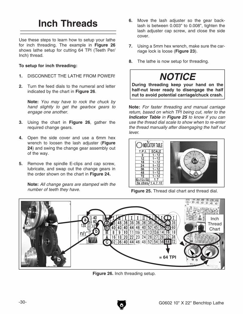
Use these steps to learn how to setup your lathe for inch threading. The example in Figure 26 shows lathe setup for cutting 64 TPI (Teeth Per/Inch) thread.
To setup for inch threading:
1. DISCONNECT THE LATHE FROM POWER!
2. Turn the feed dials to the numeral and letter indicated by the chart in Figure 26.
Note: You may have to rock the chuck by hand slightly to get the gearbox gears to engage one another.
3. Using the chart in Figure 26, gather the required change gears.
4. Open the side cover and use a 6mm hex wrench to loosen the lash adjuster (Figure 24) and swing the change gear assembly out of the way.
5. Remove the spindle E-clips and cap screw, lubricate, and swap out the change gears in the order shown on the chart in Figure 24.
Note: All change gears are stamped with the number of teeth they have.
Figure 26. Inch threading setup.
Inch Threads
Figure 25. Thread dial chart and thread dial.
= 64 TPIb
Inch Thread Chart
6. Move the lash adjuster so the gear back-lash is between 0.003" to 0.008", tighten the lash adjuster cap screw, and close the side cover.
7. Using a 5mm hex wrench, make sure the car-riage lock is loose (Figure 23).
8. The lathe is now setup for threading.
Note: For faster threading and manual carriage return, based on which TPI being cut, refer to the Indicator Table in Figure 25 to know if you can use the thread dial scale to show when to re-enter the thread manually after disengaging the half nut lever.
a
NOTICEDuring threading keep your hand on the half-nut lever ready to disengage the half nut to avoid potential carriage/chuck crash.
G0602 10" X 22" Benchtop Lathe -31-
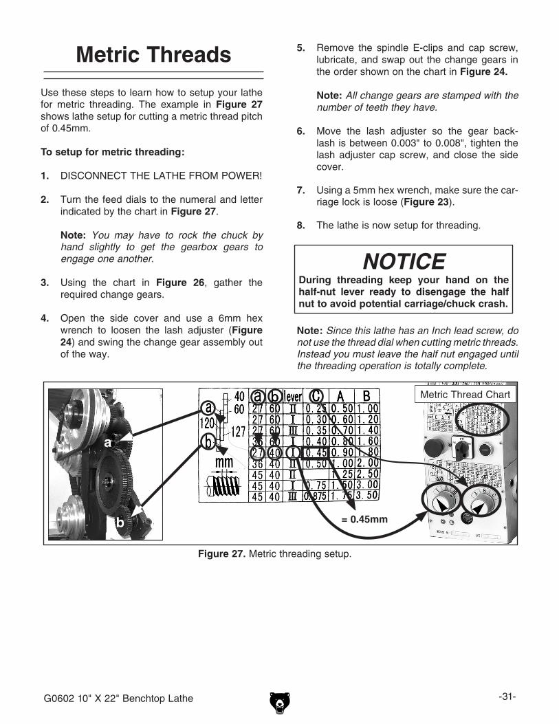
Figure 27. Metric threading setup.
Metric Thread Chart
= 0.45mmb
a
Use these steps to learn how to setup your lathe for metric threading. The example in Figure 27 shows lathe setup for cutting a metric thread pitch of 0.45mm.
To setup for metric threading:
1. DISCONNECT THE LATHE FROM POWER!
2. Turn the feed dials to the numeral and letter indicated by the chart in Figure 27.
Note: You may have to rock the chuck by hand slightly to get the gearbox gears to engage one another.
3. Using the chart in Figure 26, gather the required change gears.
4. Open the side cover and use a 6mm hex wrench to loosen the lash adjuster (Figure 24) and swing the change gear assembly out of the way.
Metric Threads 5. Remove the spindle E-clips and cap screw, lubricate, and swap out the change gears in the order shown on the chart in Figure 24.
Note: All change gears are stamped with the number of teeth they have.
6. Move the lash adjuster so the gear back-lash is between 0.003" to 0.008", tighten the lash adjuster cap screw, and close the side cover.
7. Using a 5mm hex wrench, make sure the car-riage lock is loose (Figure 23).
8. The lathe is now setup for threading.
Note: Since this lathe has an Inch lead screw, do not use the thread dial when cutting metric threads. Instead you must leave the half nut engaged until the threading operation is totally complete.
NOTICEDuring threading keep your hand on the half-nut lever ready to disengage the half nut to avoid potential carriage/chuck crash.
-32- G0602 10" X 22" Benchtop Lathe
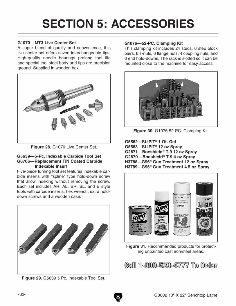
Figure 31. Recommended products for protect-ing unpainted cast iron/steel areas.
G5562—SLIPIT® 1 Qt. GelG5563—SLIPIT® 12 oz SprayG2871—Boeshield® T-9 12 oz SprayG2870—Boeshield® T-9 4 oz SprayH3788—G96® Gun Treatment 12 oz SprayH3789—G96® Gun Treatment 4.5 oz Spray
SECTION 5: ACCESSORIES
Figure 28. G1070 Live Center Set.
G1070—MT3 Live Center SetA super blend of quality and convenience, this live center set offers seven interchangeable tips. High-quality needle bearings prolong tool life and special tool steel body and tips are precision ground. Supplied in wooden box.
G1076—52-PC. Clamping KitThis clamping kit includes 24 studs, 6 step block pairs, 6 T-nuts, 6 flange nuts, 4 coupling nuts, and 6 end hold-downs. The rack is slotted so it can be mounted close to the machine for easy access.
Figure 30. G1076 52-PC. Clamping Kit.
Figure 29. G5639 5 Pc. Indexable Tool Set.
G5639—5-Pc. Indexable Carbide Tool SetG6706—Replacement TiN Coated Carbide Indexable InsertFive-piece turning tool set features indexable car-bide inserts with "spline" type hold-down screw that allow indexing without removing the screw. Each set includes AR, AL, BR, BL, and E style tools with carbide inserts, hex wrench, extra hold-down screws and a wooden case.
G0602 10" X 22" Benchtop Lathe -33-
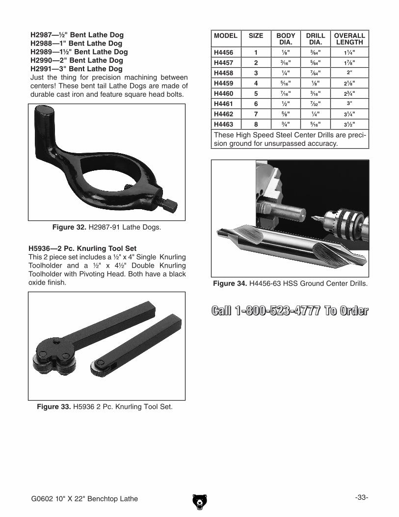
Figure 32. H2987-91 Lathe Dogs.
H2987—½" Bent Lathe DogH2988—1" Bent Lathe DogH2989—1½" Bent Lathe DogH2990—2" Bent Lathe DogH2991—3" Bent Lathe DogJust the thing for precision machining between centers! These bent tail Lathe Dogs are made of durable cast iron and feature square head bolts.
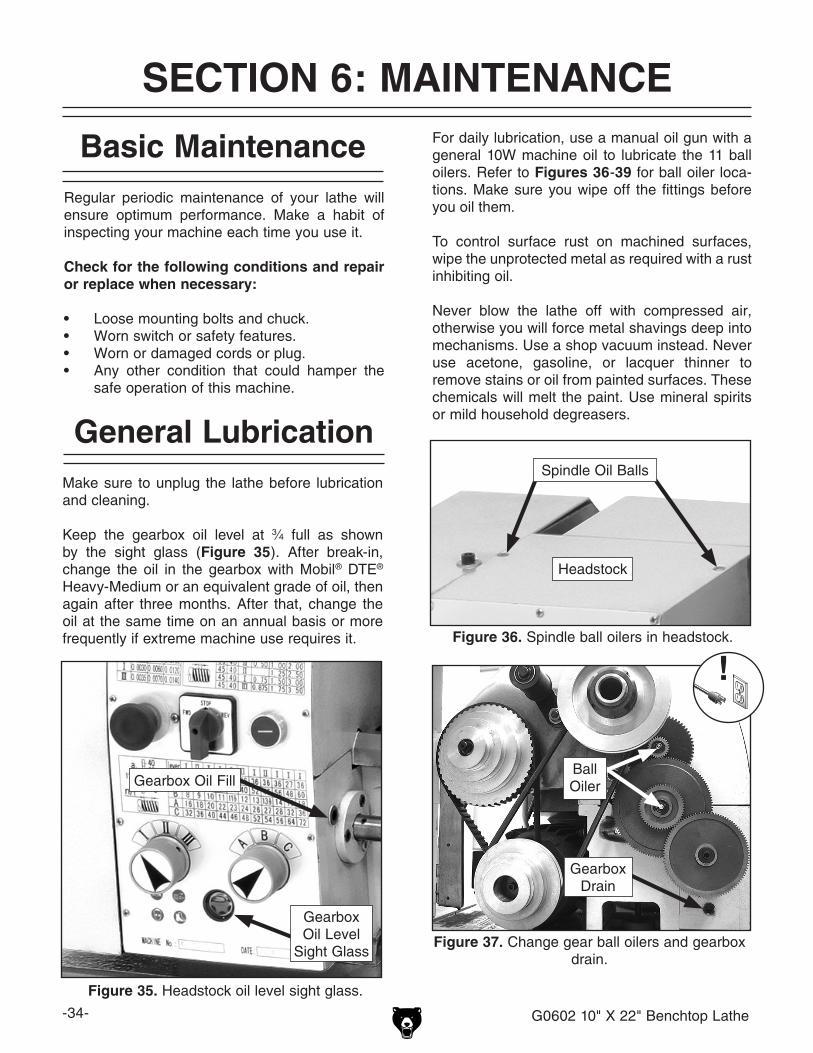
Figure 33. H5936 2 Pc. Knurling Tool Set.
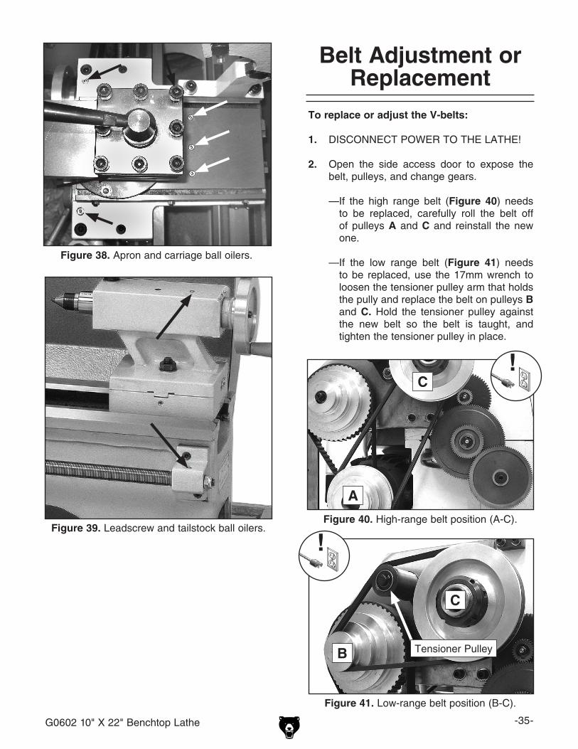
H5936—2 Pc. Knurling Tool SetThis 2 piece set includes a ½" x 4" Single Knurling Toolholder and a ½" x 4½" Double Knurling Toolholder with Pivoting Head. Both have a black oxide finish. Figure 34. H4456-63 HSS Ground Center Drills.
MODEL SIZE BODY DIA.
DRILL DIA.
OVERALL LENGTH
H4456 1 1⁄8" 3⁄64" 11⁄4"
H4457 2 3⁄16" 5⁄64" 17⁄8"
H4458 3 1⁄4" 7⁄64" 2"
H4459 4 5⁄16" 1⁄8" 21⁄8"
H4460 5 7⁄16" 3⁄16" 23⁄4"
H4461 6 1⁄2" 7⁄32" 3"
H4462 7 5⁄8" 1⁄4" 31⁄4"
H4463 8 3⁄4" 5⁄16" 31⁄2"
These High Speed Steel Center Drills are preci-sion ground for unsurpassed accuracy.
-34- G0602 10" X 22" Benchtop Lathe
SECTION 6: MAINTENANCE
Regular periodic maintenance of your lathe will ensure optimum performance. Make a habit of inspecting your machine each time you use it.
Check for the following conditions and repair or replace when necessary:
• Loose mounting bolts and chuck.• Worn switch or safety features.• Worn or damaged cords or plug.• Any other condition that could hamper the
safe operation of this machine.
Basic Maintenance
Make sure to unplug the lathe before lubrication and cleaning.
Keep the gearbox oil level at 3⁄4 full as shown by the sight glass (Figure 35). After break-in, change the oil in the gearbox with Mobil® DTE® Heavy-Medium or an equivalent grade of oil, then again after three months. After that, change the oil at the same time on an annual basis or more frequently if extreme machine use requires it.
General Lubrication
Ball Oiler
GearboxDrain
Figure 36. Spindle ball oilers in headstock.
Spindle Oil Balls
Headstock
Figure 35. Headstock oil level sight glass.
Gearbox Oil Level
Sight Glass
Gearbox Oil Fill
For daily lubrication, use a manual oil gun with a general 10W machine oil to lubricate the 11 ball oilers. Refer to Figures 36-39 for ball oiler loca-tions. Make sure you wipe off the fittings before you oil them.
To control surface rust on machined surfaces, wipe the unprotected metal as required with a rust inhibiting oil.
Never blow the lathe off with compressed air, otherwise you will force metal shavings deep into mechanisms. Use a shop vacuum instead. Never use acetone, gasoline, or lacquer thinner to remove stains or oil from painted surfaces. These chemicals will melt the paint. Use mineral spirits or mild household degreasers.
Figure 37. Change gear ball oilers and gearbox drain.
G0602 10" X 22" Benchtop Lathe -35-
Figure 38. Apron and carriage ball oilers.
Figure 39. Leadscrew and tailstock ball oilers.
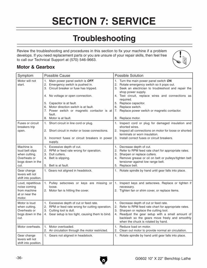
To replace or adjust the V-belts:
1. DISCONNECT POWER TO THE LATHE!
2. Open the side access door to expose the belt, pulleys, and change gears.
—If the high range belt (Figure 40) needs to be replaced, carefully roll the belt off of pulleys A and C and reinstall the new one.
—If the low range belt (Figure 41) needs to be replaced, use the 17mm wrench to loosen the tensioner pulley arm that holds the pully and replace the belt on pulleys B and C. Hold the tensioner pulley against the new belt so the belt is taught, and tighten the tensioner pulley in place.
Belt Adjustment or Replacement
Figure 40. High-range belt position (A-C).
A
C
Figure 41. Low-range belt position (B-C).
Tensioner PulleyB
C
-36- G0602 10" X 22" Benchtop Lathe
Symptom Possible Cause Possible SolutionMotor will not start.
1. Main power panel switch is OFF.2. Emergency switch is pushed in.3. Circuit breaker or fuse has tripped.
4. No voltage or open connection.
5. Capacitor is at fault.6. Motor direction switch is at fault.7. Power switch or magnetic contactor is at
fault.8. Motor is at fault.
1. Turn the main power panel switch ON.2. Rotate emergency switch so it pops out.3. Seek an electrician to troubleshoot and repair the
shop power supply.4. Test circuit, replace wires and connections as
required.5. Replace capacitor.6. Replace switch.7. Replace power switch or magnetic contactor.
8. Replace motor.
Fuses or circuit breakers trip open.
1. Short circuit in line cord or plug.
2. Short circuit in motor or loose connections.
3. Incorrect fuses or circuit breakers in power supply.
1. Inspect cord or plug for damaged insulation and shorted wires.
2. Inspect all connections on motor for loose or shorted terminals or worn insulation.
3. Install correct fuses or circuit breakers.
Machine is loud belt slips when cutting. Overheats or bogs down in the cut.
1. Excessive depth of cut.2. RPM or feed rate wrong for operation.3. Dull cutters.4. Belt is slipping.
5. Belt is at fault.
1. Decrease depth of cut.2. Refer to RPM feed rate chart for appropriate rates.3. Sharpen or replace cutters.4. Remove grease or oil on belt or pulleys/tighten belt
tensioner against low range belt.5. Replace belt.
Gear change levers will not shift into position.
1. Gears not aligned in headstock. 1. Rotate spindle by hand until gear falls into place.
Loud, repetitious noise coming from machine at or near the motor.
1. Pulley setscrews or keys are missing or loose.
2. Motor fan is hitting the cover.
1. Inspect keys and setscrews. Replace or tighten if necessary.
2. Tighten fan or shim cover, or replace items.
Motor is loud when cutting. Overheats or bogs down in the cut.
1. Excessive depth of cut or feed rate.2. RPM or feed rate wrong for cutting operation.3. Cutting tool is dull.4. Gear setup is too tight, causing them to bind.
1. Decrease depth of cut or feed rate.2. Refer to RPM feed rate chart for appropriate rates.3. Sharpen or replace the cutting tool.4. Readjust the gear setup with a small amount of
backlash so the gears move freely and smoothly when the chuck is rotated by hand.
Motor overheats. 1. Motor overloaded.2. Air circulation through the motor restricted.
1. Reduce load on motor.2. Clean out motor to provide normal air circulation.
Gear change levers will not shift into position.
1. Gears not aligned in headstock. 1. Rotate spindle by hand until gear falls into place.
Troubleshooting
Motor & Gearbox
Review the troubleshooting and procedures in this section to fix your machine if a problem develops. If you need replacement parts or you are unsure of your repair skills, then feel free to call our Technical Support at (570) 546-9663.
SECTION 7: SERVICE
G0602 10" X 22" Benchtop Lathe -37-
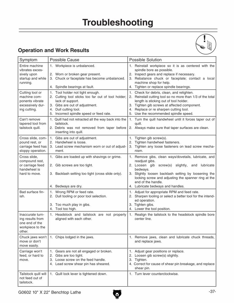
Symptom Possible Cause Possible SolutionEntire machine vibrates exces-sively upon startup and while running.
1. Workpiece is unbalanced.
2. Worn or broken gear present.3. Chuck or faceplate has become unbalanced.
4. Spindle bearings at fault.
1. Reinstall workpiece so it is as centered with the spindle bore as possible.
2. Inspect gears and replace if necessary.3. Rebalance chuck or faceplate; contact a local
machine shop for help.4. Tighten or replace spindle bearings.
Cutting tool or machine com-ponents vibrate excessively dur-ing cutting.
1. Tool holder not tight enough.2. Cutting tool sticks too far out of tool holder;
lack of support.3. Gibs are out of adjustment.4. Dull cutting tool.5. Incorrect spindle speed or feed rate.
1. Check for debris, clean, and retighten.2. Reinstall cutting tool so no more than 1/3 of the total
length is sticking out of tool holder.3. Tighten gib screws at affected component.4. Replace or re sharpen cutting tool.5. Use the recommended spindle speed.
Can't remove tapered tool from tailstock quill.
1. Quill had not retracted all the way back into the tailstock.
2. Debris was not removed from taper before inserting into quill.
1. Turn the quill handwheel until it forces taper out of quill.
2. Always make sure that taper surfaces are clean.
Cross slide, com-pound rest, or carriage feed has sloppy operation.
1. Gibs are out of adjustment.2. Handwheel is loose.3. Lead screw mechanism worn or out of adjust-
ment.
1. Tighten gib screw(s).2. Tighten handwheel fasteners.3. Tighten any loose fasteners on lead screw mecha-
nism.
Cross slide, compound rest, or carriage feed handwheel is hard to move.
1. Gibs are loaded up with shavings or grime.
2. Gib screws are too tight.
3. Backlash setting too tight (cross slide only).
4. Bedways are dry.
1. Remove gibs, clean ways/dovetails, lubricate, and readjust gibs.
2. Loosen gib screw(s) slightly, and lubricate bedways.
3. Slightly loosen backlash setting by loosening the locking screw and adjusting the spanner ring at the end of the handle.
4. Lubricate bedways and handles.
Bad surface fin-ish.
1. Wrong RPM or feed rate.2. Dull tooling or poor tool selection.
3. Too much play in gibs.4. Tool too high.
1. Adjust for appropriate RPM and feed rate.2. Sharpen tooling or select a better tool for the intend-
ed operation.3. Tighten gibs.4. Lower the tool position.
Inaccurate turn-ing results from one end of the workpiece to the other.
1. Headstock and tailstock are not properly aligned with each other.
1. Realign the tailstock to the headstock spindle bore center line.
Chuck jaws won't move or don't move easily.
1. Chips lodged in the jaws. 1. Remove jaws, clean and lubricate chuck threads, and replace jaws.
Carriage won't feed, or hard to move.
1. Gears are not all engaged or broken.2. Gibs are too tight.3. Loose screw on the feed handle. 4. Lead screw shear pin has sheared.
1. Adjust gear positions or replace.2. Loosen gib screw(s) slightly.3. Tighten.4. Correct for cause of shear pin breakage, and replace
shear pin.
Tailstock quill will not feed out of tailstock.
1. Quill lock lever is tightened down. 1. Turn lever counterclockwise.
Operation and Work Results
Troubleshooting
-38- G0602 10" X 22" Benchtop Lathe
Gib Adjustments
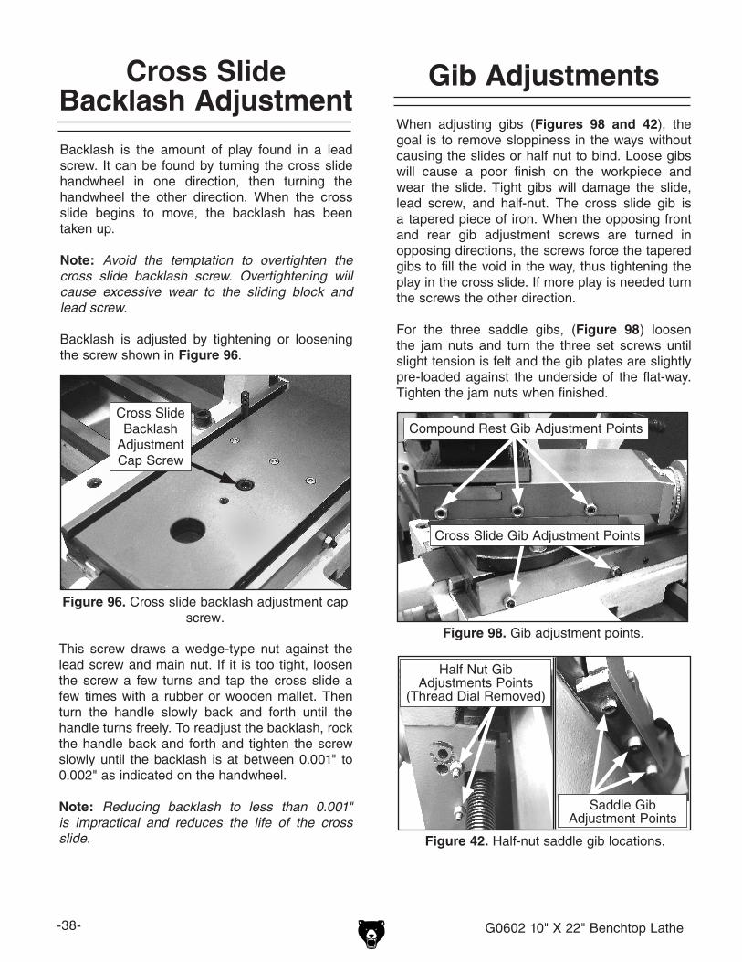
Figure 96. Cross slide backlash adjustment cap screw.
Cross Slide Backlash
Adjustment Cap Screw
Backlash is the amount of play found in a lead screw. It can be found by turning the cross slide handwheel in one direction, then turning the handwheel the other direction. When the cross slide begins to move, the backlash has been taken up.
Note: Avoid the temptation to overtighten the cross slide backlash screw. Overtightening will cause excessive wear to the sliding block and lead screw.
Backlash is adjusted by tightening or loosening the screw shown in Figure 96.
Cross Slide Backlash Adjustment
This screw draws a wedge-type nut against the lead screw and main nut. If it is too tight, loosen the screw a few turns and tap the cross slide a few times with a rubber or wooden mallet. Then turn the handle slowly back and forth until the handle turns freely. To readjust the backlash, rock the handle back and forth and tighten the screw slowly until the backlash is at between 0.001" to 0.002" as indicated on the handwheel.
Note: Reducing backlash to less than 0.001" is impractical and reduces the life of the cross slide.
Figure 98. Gib adjustment points.
Figure 42. Half-nut saddle gib locations.
When adjusting gibs (Figures 98 and 42), the goal is to remove sloppiness in the ways without causing the slides or half nut to bind. Loose gibs will cause a poor finish on the workpiece and wear the slide. Tight gibs will damage the slide, lead screw, and half-nut. The cross slide gib is a tapered piece of iron. When the opposing front and rear gib adjustment screws are turned in opposing directions, the screws force the tapered gibs to fill the void in the way, thus tightening the play in the cross slide. If more play is needed turn the screws the other direction.
For the three saddle gibs, (Figure 98) loosen the jam nuts and turn the three set screws until slight tension is felt and the gib plates are slightly pre-loaded against the underside of the flat-way. Tighten the jam nuts when finished.
Saddle Gib Adjustment Points
Half Nut Gib Adjustments Points
(Thread Dial Removed)
Cross Slide Gib Adjustment Points
Compound Rest Gib Adjustment Points

G0602 10" X 22" Benchtop Lathe -39-
Electrical Component Connections
Figure 45. Motor rotary switch and emergency stop switch (SA and SB2).
Figure 43. Motor rotary switch and ON power switch (SA and SB1).
Figure 44. External motor capacitors.
Figure 46. Motor start contactor.
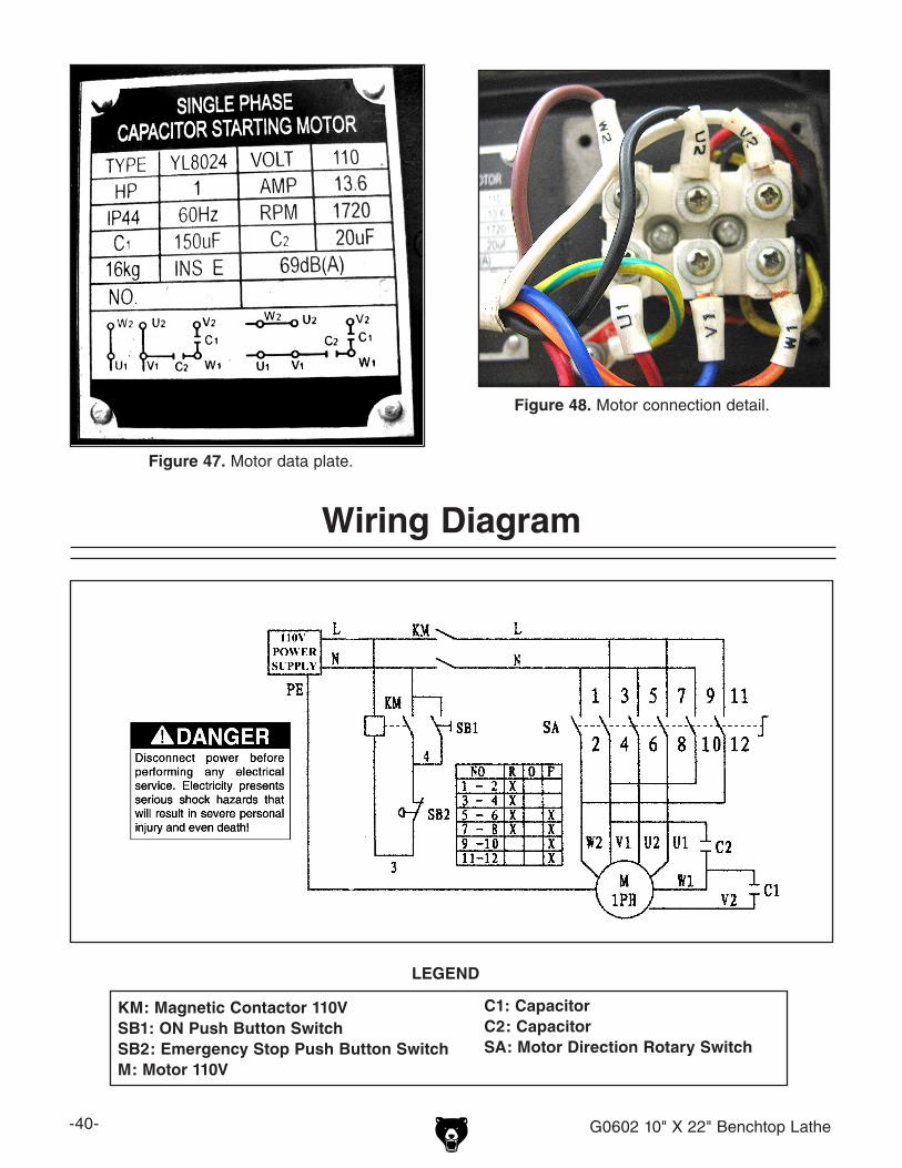
-40- G0602 10" X 22" Benchtop Lathe
Figure 48. Motor connection detail.
Figure 47. Motor data plate.
Wiring Diagram
KM: Magnetic Contactor 110VSB1: ON Push Button SwitchSB2: Emergency Stop Push Button SwitchM: Motor 110V
LEGEND
C1: CapacitorC2: CapacitorSA: Motor Direction Rotary Switch

G0602 10" X 22" Benchtop Lathe -41-
Spindle and Drive Belt
SECTION 8: PARTS
�� �
���
����
����
��
��
��
��
����
��
��
�� ��
��
��
����
��
����
��
����
��
��
����
��
����
����
����
����
����
��
����
��
��
����
������

-42- G0602 10" X 22" Benchtop Lathe
Spindle and Drive Belt PartsREF PART # DESCRIPTION REF PART # DESCRIPTION
1 P0602001 CONTROL PANEL FACE 31 P0602031 SPINDLE SHAFT
2 PS17M PHLP HD SCR M4-.7 X 6 32 P0602032 COGGED BELT 263L
5 PSB06M CAP SCREW M6-1 X 25 33 P6001 BALL BEARING 6001
6 PW03M FLAT WASHER 6MM 34 P0602034 COGGED PULLEY
7 P0602007 COMPRESSION SPRING 35 PR03M EXT RETAINING RING 12MM
8 P0602008 CLAMP 36 P0602036 SPACER
10 PSB06M CAP SCREW M6-1 X 25 37 P0602037 COGGED PULLEY
11 P0602011 SPINDLE 38 PK11M KEY 6 X 6 X 40
12 PK135M KEY 10 X 10 X 55 39 P0602039 SPACER
13 P0602013 SPACER 40 P0602040 STUD
14 P0602014 BALL BEARING (45 X 75 X 20) 41 P0602041 PLATE
15 P0602015 HEADSTOCK 42 PW04M FLAT WASHER 10MM
16 PSB14M CAP SCREW M8-1.25 X 20 43 PN02M HEX NUT M10-1.5
17 P0602017 BALL BEARING (45 X 75 X 20) 44 P0602044 SPINDLE SHAFT
18 PSB02M CAP SCREW M6-1 X 20 45 P0602045 BALL BEARING (12 X 28 X 8)
19 P0602019 SPACER 46 P0602046 ROLLER
20 P0602020 GEAR 47 PR20M INT RETAINING RING 28MM
21 PVM27A V-BELT M-27.5 3L275 48 PR03M EXT RETAINING RING 12MM
22 P0602022 PULLEY 49 P0602049 COVER
23 PVM33 V-BELT M-33 3L330 51 PN06M HEX NUT M5-.8
24 P0602024 SPANNER NUT M30 X 1.5 52 P0602052 COVER
25 P0602025 BRACKET PLATE 53 PS08M PHLP HD SCR M5-.8 X 12
26 PLW06M LOCK WASHER 10MM 54 P0602054 5" 3-JAW CHUCK
27 PN02M HEX NUT M10-1.5 54-1 P0602054-1 3-JAW CHUCK JAWS (SET OF 3)
28 PW04M FLAT WASHER 10MM 55 P0602055 6.5" 4-JAW CHUCK
29 PSB50M CAP SCREW M5-.8 X 10 55-1 P0602055-1 4-JAW CHUCK JAWS (SET OF 4)
30 PW02M FLAT WASHER 5MM
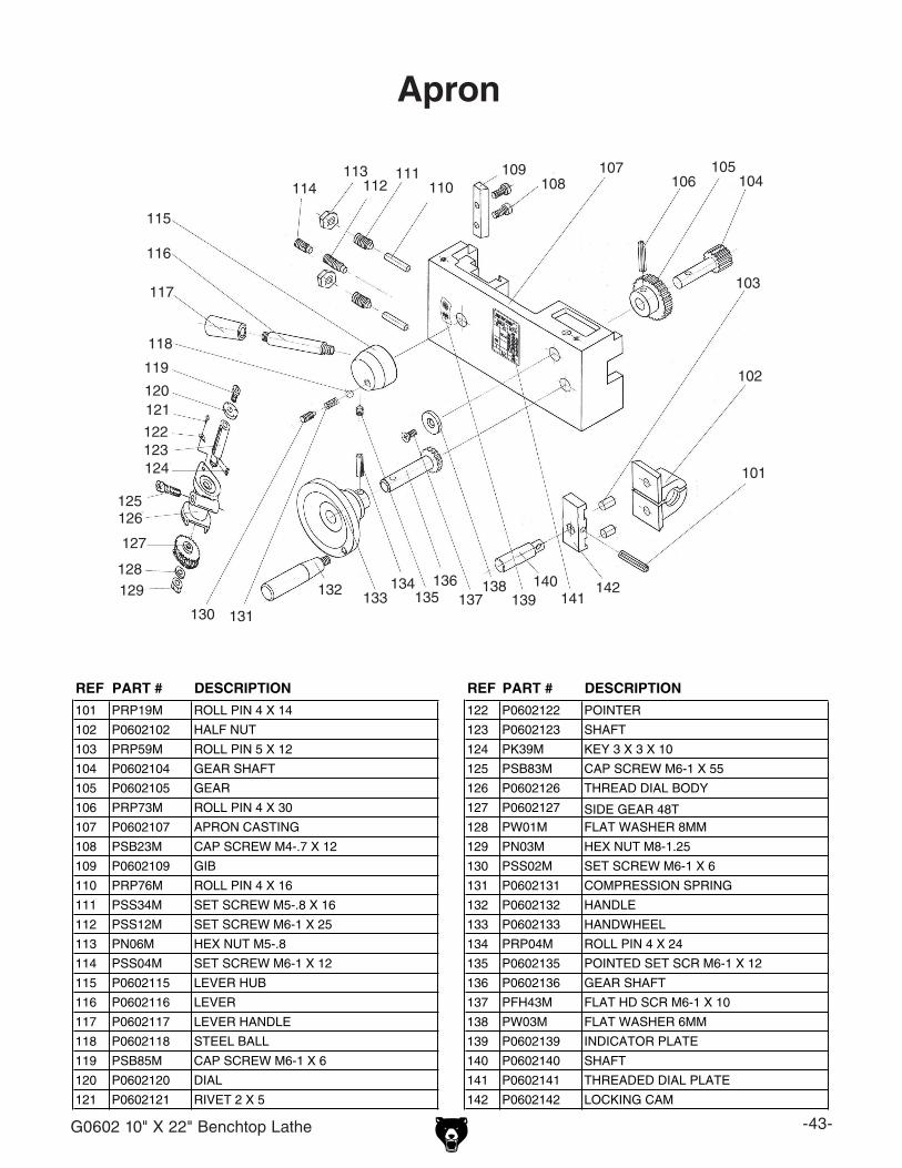
G0602 10" X 22" Benchtop Lathe -43-
Apron
���
���
���
������
������
������
������
������
���
���
���
���
���
���
������
���������
������
���
������
��� ���
��� ������
������
������
������
������
REF PART # DESCRIPTION REF PART # DESCRIPTION
101 PRP19M ROLL PIN 4 X 14 122 P0602122 POINTER
102 P0602102 HALF NUT 123 P0602123 SHAFT
103 PRP59M ROLL PIN 5 X 12 124 PK39M KEY 3 X 3 X 10
104 P0602104 GEAR SHAFT 125 PSB83M CAP SCREW M6-1 X 55
105 P0602105 GEAR 126 P0602126 THREAD DIAL BODY
106 PRP73M ROLL PIN 4 X 30 127 P0602127 SIDE GEAR 48T107 P0602107 APRON CASTING 128 PW01M FLAT WASHER 8MM
108 PSB23M CAP SCREW M4-.7 X 12 129 PN03M HEX NUT M8-1.25
109 P0602109 GIB 130 PSS02M SET SCREW M6-1 X 6
110 PRP76M ROLL PIN 4 X 16 131 P0602131 COMPRESSION SPRING
111 PSS34M SET SCREW M5-.8 X 16 132 P0602132 HANDLE
112 PSS12M SET SCREW M6-1 X 25 133 P0602133 HANDWHEEL
113 PN06M HEX NUT M5-.8 134 PRP04M ROLL PIN 4 X 24
114 PSS04M SET SCREW M6-1 X 12 135 P0602135 POINTED SET SCR M6-1 X 12
115 P0602115 LEVER HUB 136 P0602136 GEAR SHAFT
116 P0602116 LEVER 137 PFH43M FLAT HD SCR M6-1 X 10
117 P0602117 LEVER HANDLE 138 PW03M FLAT WASHER 6MM
118 P0602118 STEEL BALL 139 P0602139 INDICATOR PLATE
119 PSB85M CAP SCREW M6-1 X 6 140 P0602140 SHAFT
120 P0602120 DIAL 141 P0602141 THREADED DIAL PLATE
121 P0602121 RIVET 2 X 5 142 P0602142 LOCKING CAM

-44- G0602 10" X 22" Benchtop Lathe
���
���
���
���
���
���
���
���
���
���
���
���
���
���
���
���
����
���
���
���
������
���
���
���
���
���
���
���
��� ���
���
������
Tool Holder and Compound Rest
REF PART # DESCRIPTION REF PART # DESCRIPTION
201 P0602201 COMPOUND SLIDE 217A PSS19M SET SCREW M8-1.25 X 30
202 P0602202 SWIVEL BASE 217A-1 PN03M FLAT WASHER 8MM
203 P0602203 GIB 218 P0602218 HANDLE
204 P0602204 CLAMPING RING 219 P0602219 HANDLE HUB
205 P0602205 GRADUATED DIAL 220 P0602220 TOOL REST
206 P0602206 BARREL NUT 221 P0602221 RUB SPACER
207 P0602207 DOWEL PIN 222 P0602222 SLIDE PLATE
208 P0602208 TOOL POST STUD 223 P0602223 LEAD SCREW
209 PW01M FLAT WASHER 8MM 224 P0602224 LEAD SCREW MOUNT
210 P0602210 DOWEL PIN 225 P0602225 GRADUATED DIAL
211 P0602211 COMPRESSION SPRING 226 P0602226 HANDWHEEL
212 P0602212 BULLNOSE CAP SCR M8-1.25 X 29 227 P0602227 HANDLE
213 PSB31M CAP SCREW M8-1.25 X 25 228 PK03M KEY 3 X 3 X 8
214 PSB26M CAP SCREW M6-1 X 12 229 P0602229 POINTER
215 PSS34M SET SCREW M5-.8 X 16 230 P0602230 THREADED COLLAR
216 PN06M HEX NUT M5-.8 231 PSS17M SET SCREW M8-1.25 X 6
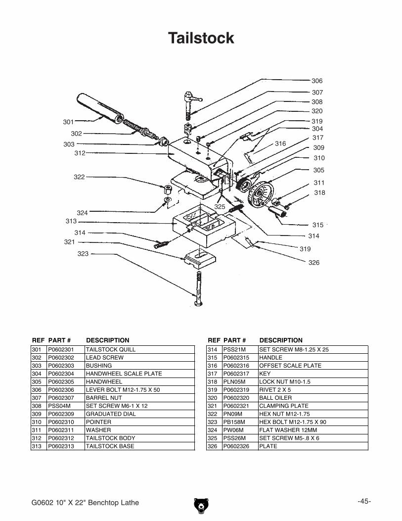
G0602 10" X 22" Benchtop Lathe -45-
Tailstock
���
���
���
���
���
���
������
���
���
���
���
������
������
���
���
���
���
���
���
������
���
���
���
���
REF PART # DESCRIPTION REF PART # DESCRIPTION301 P0602301 TAILSTOCK QUILL 314 PSS21M SET SCREW M8-1.25 X 25302 P0602302 LEAD SCREW 315 P0602315 HANDLE303 P0602303 BUSHING 316 P0602316 OFFSET SCALE PLATE304 P0602304 HANDWHEEL SCALE PLATE 317 P0602317 KEY305 P0602305 HANDWHEEL 318 PLN05M LOCK NUT M10-1.5306 P0602306 LEVER BOLT M12-1.75 X 50 319 P0602319 RIVET 2 X 5307 P0602307 BARREL NUT 320 P0602320 BALL OILER308 PSS04M SET SCREW M6-1 X 12 321 P0602321 CLAMPING PLATE309 P0602309 GRADUATED DIAL 322 PN09M HEX NUT M12-1.75310 P0602310 POINTER 323 PB158M HEX BOLT M12-1.75 X 90311 P0602311 WASHER 324 PW06M FLAT WASHER 12MM312 P0602312 TAILSTOCK BODY 325 PSS26M SET SCREW M5-.8 X 6313 P0602313 TAILSTOCK BASE 326 P0602326 PLATE
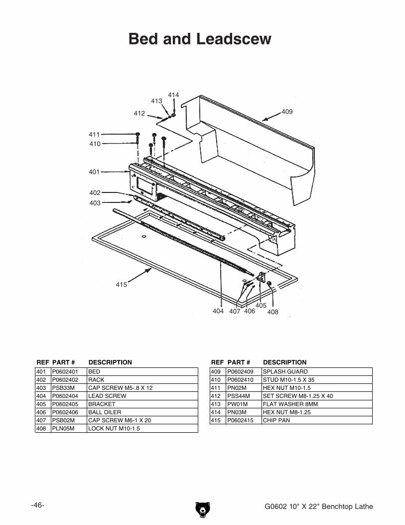
-46- G0602 10" X 22" Benchtop Lathe
Bed and Leadscew
���
���
���
������
������ ���
���
������
���
������
���
REF PART # DESCRIPTION REF PART # DESCRIPTION401 P0602401 BED 409 P0602409 SPLASH GUARD402 P0602402 RACK 410 P0602410 STUD M10-1.5 X 35403 PSB33M CAP SCREW M5-.8 X 12 411 PN02M HEX NUT M10-1.5404 P0602404 LEAD SCREW 412 PSS44M SET SCREW M8-1.25 X 40405 P0602405 BRACKET 413 PW01M FLAT WASHER 8MM406 P0602406 BALL OILER 414 PN03M HEX NUT M8-1.25407 PSB02M CAP SCREW M6-1 X 20 415 P0602415 CHIP PAN408 PLN05M LOCK NUT M10-1.5
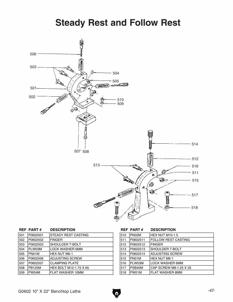
G0602 10" X 22" Benchtop Lathe -47-
Steady Rest and Follow Rest
���
���
���
���
���
���
��� ���
���
���
���
���
���
���
���
���
���
���
REF PART # DESCRIPTION REF PART # DESCRIPTION501 P0602501 STEADY REST CASTING 510 PN02M HEX NUT M10-1.5502 P0602502 FINGER 511 P0602511 FOLLOW REST CASTING503 P0602503 SHOULDER T-BOLT 512 P0602512 FINGER504 PLW03M LOCK WASHER 6MM 513 P0602513 SHOULDER T-BOLT505 PN01M HEX NUT M6-1 514 P0602514 ADJUSTING SCREW506 P0602506 ADJUSTING SCREW 515 PN01M HEX NUT M6-1507 P0602507 CLAMPING PLATE 516 PLW03M LOCK WASHER 6MM508 PB125M HEX BOLT M12-1.75 X 65 517 PSB40M CAP SCREW M8-1.25 X 35509 PW04M FLAT WASHER 10MM 518 PW01M FLAT WASHER 8MM
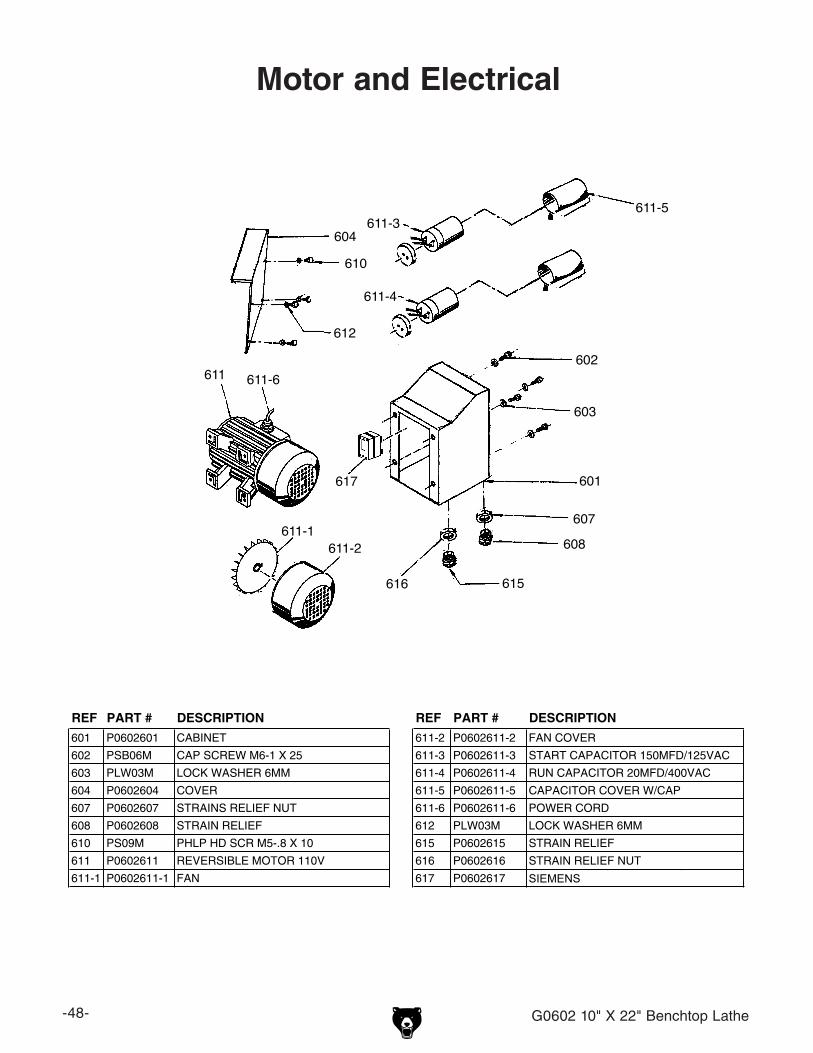
-48- G0602 10" X 22" Benchtop Lathe
Motor and Electrical
601
602
603
604
607
608
610
611
611-1611-2
611-3
611-4
611-6
612
615616
617
611-5
REF PART # DESCRIPTION REF PART # DESCRIPTION
601 P0602601 CABINET 611-2 P0602611-2 FAN COVER
602 PSB06M CAP SCREW M6-1 X 25 611-3 P0602611-3 START CAPACITOR 150MFD/125VAC
603 PLW03M LOCK WASHER 6MM 611-4 P0602611-4 RUN CAPACITOR 20MFD/400VAC
604 P0602604 COVER 611-5 P0602611-5 CAPACITOR COVER W/CAP
607 P0602607 STRAINS RELIEF NUT 611-6 P0602611-6 POWER CORD
608 P0602608 STRAIN RELIEF 612 PLW03M LOCK WASHER 6MM
610 PS09M PHLP HD SCR M5-.8 X 10 615 P0602615 STRAIN RELIEF
611 P0602611 REVERSIBLE MOTOR 110V 616 P0602616 STRAIN RELIEF NUT
611-1 P0602611-1 FAN 617 P0602617CONTACTOR�3TB41�22E�110V�SIEMENS
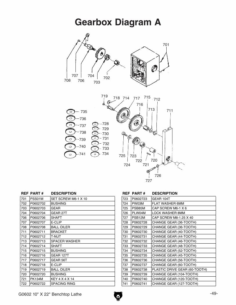
G0602 10" X 22" Benchtop Lathe -49-
���
������
������
������
���
���
���
��� ���
���
���������
������
���
���
������
���������������������
���
���
���
���
���
���
���
������
REF PART # DESCRIPTION REF PART # DESCRIPTION701 PSS01M SET SCREW M6-1 X 10 723 P0602723 GEAR 104T702 P0602702 BUSHING 724 PW03M FLAT WASHER 6MM703 P0602703 GEAR 725 PSB85M CAP SCREW M6-1 X 6704 P0602704 GEAR 27T 726 PLW04M LOCK WASHER 8MM706 P0602706 SHAFT 727 PSB12M CAP SCREW M8-1.25 X 40707 P0602707 E-CLIP 728 P0602728 CHANGE GEAR (36-TOOTH)708 P0602708 BALL OILER 729 P0602729 CHANGE GEAR (36-TOOTH)711 P0602711 BRACKET 730 P0602730 CHANGE GEAR (40-TOOTH)712 P0602712 T-NUT 731 P0602731 CHANGE GEAR (44-TOOTH)713 P0602713 SPACER WASHER 732 P0602732 CHANGE GEAR (46-TOOTH)714 P0602714 SHAFT 733 P0602733 CHANGE GEAR (48-TOOTH)715 P0602715 BUSHING 734 P0602734 CHANGE GEAR (52-TOOTH)716 P0602716 GEAR 127T 735 P0602735 CHANGE GEAR (45-TOOTH)717 P0602717 GEAR 56T 736 P0602736 CHANGE GEAR (56-TOOTH)718 P0602718 E-CLIP 737 P0602737 CHANGE GEAR (60-TOOTH)719 P0602719 BALL OILER 738 P0602738 PLASTIC DRIVE GEAR (60-TOOTH)720 P0602720 BUSHING 739 P0602739 CHANGE GEAR (104-TOOTH)721 PK134M KEY 4 X 4 X 14 740 P0602740 CHANGE GEAR (120-TOOTH)722 P0602722 SPACING RING 741 P0602741 CHANGE GEAR (127-TOOTH)
Gearbox Diagram A
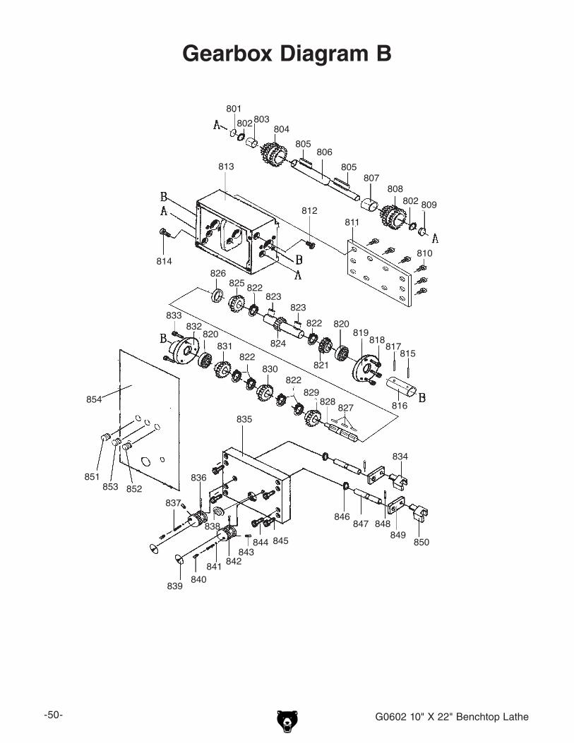
-50- G0602 10" X 22" Benchtop Lathe
Gearbox Diagram B
801802803 804
806
807808
809
810
811812
813
814
815
816
817818819
820
821
822823
824
825826
828829
830
831
832833
834
835
836
837
838
839 840841 842
843844 845
846847 848
849850
851852853
854
805
805
802
827
822
822
820
822823

G0602 10" X 22" Benchtop Lathe -51-
REF PART # DESCRIPTION REF PART # DESCRIPTION801 P0602801 PLUG 828 P0602828 SHAFT802 P0602802 O-RING 829 P0602829 GEAR 33T803 P0602803 BUSHING 830 P0602830 GEAR 30T804 P0602804 CLUSTER GEAR 30-36-33T 831 P0602831 GEAR 35T805 PK133M KEY 4 X 4 X 50 832 P0602832 FLANGE806 P0602806 SHAFT 833 PSB01M CAP SCREW M6-1 X 16807 P0602807 BUSHING 834 P0602834 SHIFT FORK808 P0602808 CLUSTER GEAR 22-44-33T 835 P0602835 COVER809 P0602809 PLUG 836 PRP05M ROLL PIN 5 X 30810 PSB50M CAP SCREW M5-.8 X 10 837 P0602837 COMPRESSION SPRING811 P0602811 COVER 838 P0602838 SIGHT GLASS812 P0602812 PLUG 839 P0602839 POINTER DISK813 P0602813 GEAR BOX CASE 840 PSS01M SET SCREW M6-1 X 10814 P0602814 DRAIN PLUG 841 P0602841 STEEL BALL815 P0602815 SHEAR PIN 5 X 20 842 P0602842 SHIFT HUB816 P0602816 COLLAR 843 PSS01M SET SCREW M6-1 X 10817 P0602817 SHEAR PIN 5 X 20 844 PSB37M CAP SCREW M6-1 X 50818 PSB26M CAP SCREW M6-1 X 12 845 PSB02M CAP SCREW M6-1 X 20819 P0602819 FLANGE 846 P0602846 O-RING820 P6202 BALL BEARING 6202 847 P0602847 SHAFT821 P0602821 GEAR 33T 848 PRP03M ROLL PIN 5 X 20822 P0602822 EXT RETAINER RING 12MM 849 P0602849 SHIFT LEVER823 PK29M KEY 4 X 4 X 8 850 P0602850 SHIFT FORK824 P0602824 GEAR SHAFT 22T 851 P0602851 EMERGENCY OFF SWITCH825 P0602825 GEAR 44T 852 P0602852 ON PUSHBUTTON SWITCH826 P0602826 COLLAR 853 P0602853 MOTOR ROTATION SWITCH827 PK132M KEY 4 X 4 X10 854 P0602854 CONTROL PANEL
Gearbox Diagram B Parts
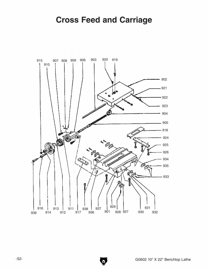
-52- G0602 10" X 22" Benchtop Lathe
Cross Feed and Carriage
���
���
���
���
���
������ ��� ������
������
������
���
������
���
������
���
���
���
���
���
���
������
���
������
���
���
���
���
���������
���

G0602 10" X 22" Benchtop Lathe -53-
REF PART # DESCRIPTION REF PART # DESCRIPTION
901 P0602901 SADDLE 921 P0602921 DOWEL PIN
902 P0602902 CROSS�SLIDE�V2.08.07 922 PSS34M SET SCREW M5-.8 X 16
903 P0602903 GIB 923 PN06M HEX NUT M5-.8
904 P0602904 CROSS SLIDE NUT 924 P0602924 APRON TENSION BAR
905 P0602905 LEAD SCREW 925 PW03M FLAT WASHER 6MM
906 P0602906 HOUSING 926 PSB01M CAP SCREW M6-1 X 16
907 PSB31M CAP SCREW M8-1.25 X 25 927 P0602927 CLIP
908 P0602908 PLATE 928 PSS25M SET SCREW M6-1 X 20
909 P0602909 RIVET 2 X 5 929 PN01M HEX NUT M6-1
910 P0602910 GRADUATED DIAL 930 PSB48M CAP SCREW M6-1 X 35
911 PK105M KEY 3 X 3 X 6 931 P0602931 WIPER
912 P0602912 COMPRESSION SPRING 932 P0602932 WIPER CLAMP
913 P0602913 HANDWHEEL 933 PS07M PHLP HD SCR M4-.7 X 8
914 P0602914 SPECIAL HEX NUT 934 P0602934 WAY COVER
915 PSS17M SET SCREW M8-1.25 X 6 935 P0602935 COVER MOUNT
916 P0602916 HANDLE 936 P0602936 OIL PORT
917 P0602917 SLIDE BLOCK 937 PSB40M CAP SCREW M8-1.25 X 35
918 P0602918 CHIP GUARD 938 PSB48M CAP SCREW M6-1 X 35
919 PSB26M CAP SCREW M6-1 X 12 939 P0602939 SPECIAL SHOULDER BOLT
920 PSS11M SET SCREW M6-1 X 16
Cross Feed and Carriage Parts

-54- G0602 10" X 22" Benchtop Lathe
Grizzly Industrial, Inc. warrants every product it sells for a period of 1 year to the original purchaser from the date of purchase. This warranty does not apply to defects due directly or indirectly to misuse, abuse, negligence, accidents, repairs or alterations or lack of maintenance. This is Grizzly’s sole written warranty and any and all warranties that may be implied by law, including any merchantability or fitness, for any par-ticular purpose, are hereby limited to the duration of this written warranty. We do not warrant or represent that the merchandise complies with the provisions of any law or acts unless the manufacturer so warrants. In no event shall Grizzly’s liability under this warranty exceed the purchase price paid for the product and any legal actions brought against Grizzly shall be tried in the State of Washington, County of Whatcom.
We shall in no event be liable for death, injuries to persons or property or for incidental, contingent, special, or consequential damages arising from the use of our products.
To take advantage of this warranty, contact us by mail or phone and give us all the details. We will then issue you a “Return Number,’’ which must be clearly posted on the outside as well as the inside of the carton. We will not accept any item back without this number. Proof of purchase must accompany the merchandise.
The manufacturers reserve the right to change specifications at any time because they constantly strive to achieve better quality equipment. We make every effort to ensure that our products meet high quality and durability standards and we hope you never need to use this warranty.
Please feel free to write or call us if you have any questions about the machine or the manual.
Thank you again for your business and continued support. We hope to serve you again soon.
WARRANTY AND RETURNS

G0602 10" X 22" Benchtop Lathe -55-
�������
��������������
���������������������������������������������������������������������������������� �
������������������������������������������������������������������������������������
����� ����������������������� ������������������������������� ���� ���������������������
���������������������������� ������ ������������������������ ���������������������������
���������������������������� ������������������������������� ���������������������������
�������������
�����������������������������������������������������������������������������������������������������������������������������������������������������������������������������������������������������
��� ���������������������������� ����� �������������� � ���� ������� ����� �������� ����� ���������� � ������������ ����� ������
��� �����������������������������������������������������
��� �������������������������������������� ����� ���������������� � ���� ���������������� ����� ���������������� ����� ���������������� � ���� ���������������� ����� ��������
��� ������������������������ ����� ������ � ���� ������ ����� ������ ����� ������ � ���� ������ ����� ���
��� ������������������������������������������������� ����� ���������� ����� ���������� ����� ������������ � �������������
��� ������������������������������������������������ ����� ���� ����� ���� ����� ���� � �������
��� ��������������������������������������������������� ���������� ��������
��� ���������������������������������������������������� ���������� ��������
��� ��������������������������������������������������������������������������������������� �������������������������������������������� ���������� ��������
���� �������������������������������������������������������������������������������
� ����������������������������������������������������������������������������������
� ����������������������������������������������������������������������������������
� ����������������������������������������������������������������������������������
���� ����������������� ������������������� ��������������� ��������� ����������������������� �������������������������� �������������� ����������������������� ������������ �����������������
���� ��������������������� ������������������� ����������������������� ����������������������� ��������������������� ��������������������� �������������� �������� �������������� ������������
���� ��������������������� �������� ��������������� ����������������� ������������� ������������ ������������������� ������������������������ ������

��������������������������������������
����������������������
����������������������
���������������������������������������������������������������
��������������
�����������������������������������
�������������������������������������
��������������������������������������
�����������������������������������


�����������������������������������������������������������������������
����
�����������������
��������������������������������
���������������������������������
�������������������������������������������������������������������������
���������������������������������������