Embed Size (px)
Citation preview

Gridshellmanual
Steinar Hillersøy DyvikJohn Haddal Mork

authors: Steinar Hillersøy Dyvik, John Haddal Morksupervisor: Bendik ManumCo-supervisor: Anders Rønnquist, Nathalie Labonnote
This manual is a part of a master thesis project at nTnu, spring 2015.
This project is inspired by the work of the gridshell.it group. a special thanks to sergio
Pone, Sofia Colabella and their team!

4
6
8
20
26
39
56
60
66
Contents
What is a gridshell?
Dictionary
The Shape
Scale modeling
Defining material properties
How to build
Budget Software
Reference projects

4
EXPLAINATION
A gridshell is a structure which derives its strength from its double curvature (in a similar way that a fabric structure derives
strength from double curvature), but is constructed of a grid or lattice.
Wikipedia
WhaT is a Gridshell?
+ =Grid Shell Gridshell

5
WhaT is a Gridshell?
shortly said, a shell is a construction type that carries loads through membrane forces, or in-plane stresses, rather than bending and shear forces. While a concrete shell is a continuous surface, a gridshell is divided in a grid of smaller elements.
a way to create gridshells are the kinematic construction process. it consists of building a rectangular or quadratic grid flat, and then deform it into shape by pulling together or lift parts of the grid. Wood is an appropriate material, because of its good bending attributes. it is fairly simple to construct a timber gridshell out of straight elements
The model and process described in this manual, is based on this construction method.
Why gridshell?The main reason to pick a gridshell construction is not only based on performance, efficiency and cost, but on architectural shape. Based on a gridshell, one can construct spectacular shapes and characteristic buildings. in addition you have got the spatial attributes, which is important for the use of the building. A self bearing construction gives flexibility in the interior.
How gridshell?The shape of the gridshell must be structural, which demands an understanding from the architect and collaboration with the structural engineer. One can not make decisions solely based on design ideas but have to do it in harmony with the structural shape. also, the structure must be stable during the whole construction process.
This model and process described in this manual, describes how designing and construction could be done in such a manner.

6
Kurvatur = TverrsnittsøgdKonstant
diCTiOnarY
Anchor Points is the same as foundation.
Bending strength,see Flexural strength.
Catenary is the shape of a hanging chain or cable supported at the ends. The inverted shape is ideal for compression only structures. The shape is also called funicular. (see page 12). Compressive strength is the capacity of a material or structure to withstand loads tending to reduce size.
Curvature is a measure of how a line deviates from beeing flat. See Radius of curvature.
Dynamic relaxation is a numerical method that can be used for form finding for cable and fabric structures. By adding different forces, it aims to find a state, or geometry where all forces are in equilibrium.
E-module, see Youngs modulus.
an Elastic modulus is a number that measures an object or substance’s resistance to being deformed elastically (i.e., non-permanently) when a force is applied to it. it includes Young’s modulus (e), shear modulus (G) and Bulk modulus (K).
Equilibrium is a state when the system (eg. a gridshell) is in balance, resulting in no internal shapual change.
Flexural strength is defined as a material’s ability to resist deformation under load. Flexural stress causes both compressive and tensile stresses, and is similar to tensile strength for homogenous materials. see page 36.

7
diCTiOnarY
Finite Element Method, or Fem is simply said an advanced method of structural analysis. it divides the structure into smaller parts, finite elements, and adds material values and loads to calculate load distribution.
Funicular, see catenary.
Grasshopper is a graphical programming plugin for rhino. see page 50.
a Particle spring system is a method of formfinding, that is a collection of points collected by springs and acted on by external forces. This method is implemented in our process using Kangaroo for rhino.
Radius of curvature is mathematically the inverse of curvature, r=1/k. it is on a point on a curve, defined as the radius of a circle that best approximates that curve. The maximal bending of a wood lath is defined with a ‘smallest possible’ radius. (See page 36).
Rhino is a nurBs based Cad software. (see page 50).
Tensile strength, or Ultimate strength is the maximum stress a material can withstand beeing stretched or pulled.
Karamba is an element analysis plugin for Grasshopper. see page 50. Kangaroo is a physics engine plug-in for Grasshopper. see page 50.
The segment-lath is the “weaved” lath-principle developed during this master-thesis.
Shear modulus describes a material’s response to shear stress and is defined as the ratio of shear stress to the shear strain.
Young’s modulus is a measure of stiffness of a material, along an axis to the strain. For material properties of wood see page 36.
Definitions from wikipedia


The shaPe

THE SHAPE
10
EXPLAINATION
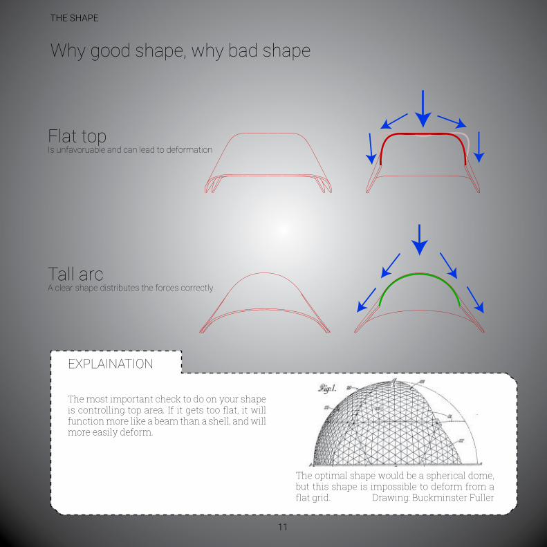
There are many different parameters that decides if it is a good shape or a bad shape. Generally, form follow function, but when it comes to gridshells, forms mostly follows forces.
1. Bad because it is too flat on the top.2. Good because it is doubled curved.3. OK because it is very curved in one direction, but is straight in the other.
4. A good, doubled curved shape. A good shape doesn’t have to be symetrical.5. Only singled curved and has kinks in it’s curvature.6. OK shape, but not good because the edges are cantelivering too much.7. Good. Curved in two directions.8. Concidering only shape, it is perfect, but it is not possible to create a gridshell like that from a flat grid.
Good and bad shape
1: Bad shape
5: Bad shape 6: OK shape
2: Good shape
7: Good shape 8: OK shape
4: Good shape3: OK shape
THE SHAPE
11
EXPLAINATION
The optimal shape would be a spherical dome, but this shape is impossible to deform from a flat grid. Drawing: Buckminster Fuller
The most important check to do on your shape is controlling top area. If it gets too flat, it will function more like a beam than a shell, and will more easily deform.
Why good shape, why bad shape
Flat topis unfavoruable and can lead to deformation
Tall arca clear shape distributes the forces correctly

THE SHAPE
12
EXPLAINATION
The circle and the parabel are easy to draw, but the catanary curve is the perfect curve for eaven load distributrion.
Wikipedias definition: In physics and geometry, a catenary is the curve that an idealized hanging chain or cable assumes under its own weight when supported only at its ends.
Catanary curves works only in tension. When flipped the curve will be in compression. Since the shell is very thin, it doesn’t have any bending capacity and has to absorbe most forces through compression.
Taking into account material parameters, such as bending capacity, we also know that this shape is not optimal for gridshell.
Curve Principles
Circle Parabel Catanary

THE SHAPE
13
Curve principles
P: Kamel 15, wikipedia
THE SHAPE
14
EXPLAINATION
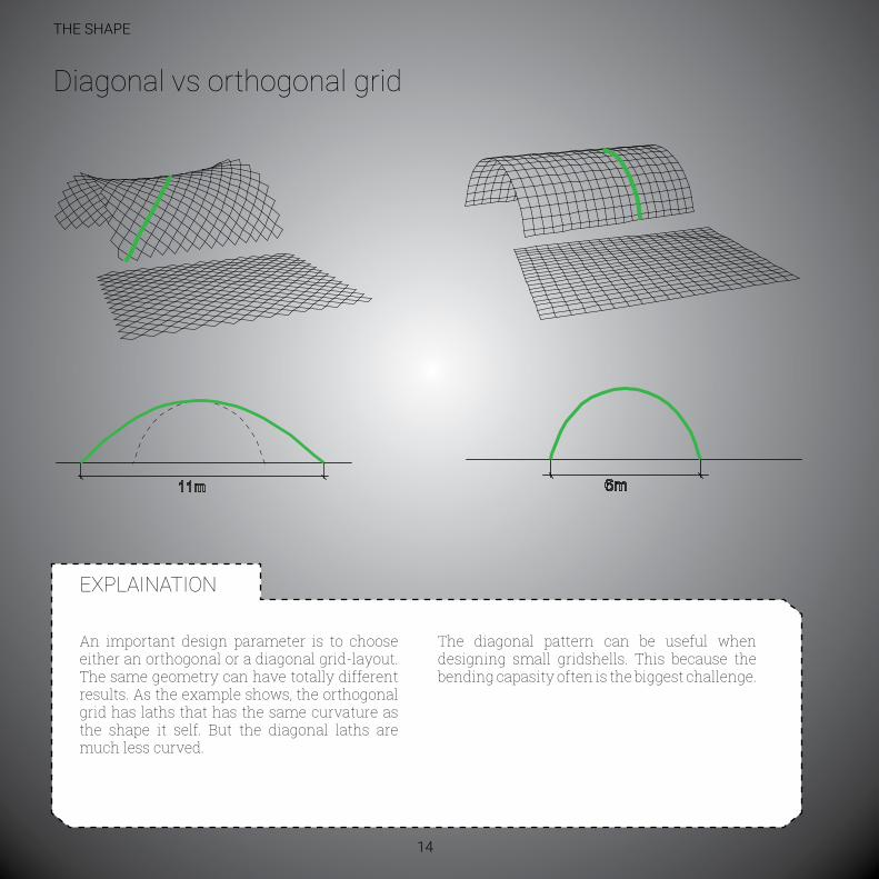
An important design parameter is to choose either an orthogonal or a diagonal grid-layout. The same geometry can have totally different results. As the example shows, the orthogonal grid has laths that has the same curvature as the shape it self. But the diagonal laths are much less curved.
The diagonal pattern can be useful when designing small gridshells. This because the bending capasity often is the biggest challenge.
diagonal vs orthogonal grid

THE SHAPE
15
EXPLAINATION
Both examples above have the same anchorpoints and the same original grid properties.
The grid-direction determines how the forces are being distributed through the laths, and
this affects the form-finding of the shape.The orthogonal grid is pushed to the limits of its curvature, while the diagonal gird still can handle a taller top and smaller distance between anchors.
diagonal vs orthogonal grid
diagonal Orthogonal

THE SHAPE
16
eXPlainaTiOn
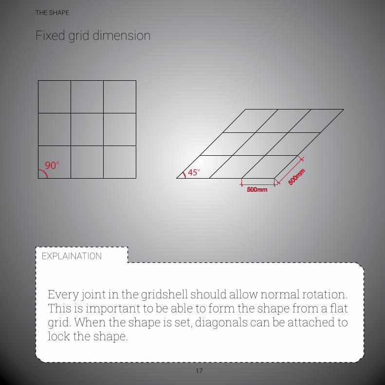
An important precondition is that every member in the gridshell has a fixed length. This counts for both the flat grid, during the shaping and for the final shape.
Fixed grid dimension
THE SHAPE
17
EXPLAINATION
Untempost qui tenimin ihitium quae. Tecus, sim aliam at lam sit faccatur, cum autatum ipis erumqui tempore rerovitae. Nemporum aboresequi dolloru ptatatur audita dolupiciatem aut quodis sim que veliqui tem eossunda pra exere.
Qudolest, int idem que id quo quia pra sunt pro tet unto blam, quide num
Every joint in the gridshell should allow normal rotation. This is important to be able to form the shape from a flat grid. When the shape is set, diagonals can be attached to lock the shape.
Fixed grid dimension
eXPlainaTiOn

THE SHAPE
18
EXPLAINATION
The kinematic construciton process is done by forcing a flat grid into its shape.
A key element in this process is placing the anchor points. In addition to the material carachteristics of the wood, this is what shapes the structure. In the same way a line (straight beam) takes the shape of a curve when
pushing the ends together, the flat grid takes the shape of a shell when the anchorpoints is moved. See more at page 63.
anchor point controlled

THE SHAPE
19
EXPLAINATION
These screenshots from Karamba shows that small anchor-point transformations, leads to big deformation changes.
Moving the center of the anchor-line 30 cm, removes the large deformations (green color).
This is why it is very important to replicate the digital shape as good as possible. Small differences changes the load distribution totally.
small changes - big impact
Green indicates high (relative) deformation.
Yellow indicates no (relative) deformation
Moving the center of the anchor line 30 cm changes the load distribution dramatically
Knowing what a good shape looks like, and how to control it is very important

sCale mOdelinG

SCALE MODELING
22
EXPLAINATION
To get a feeling on how forces apply to the grid, scale modeling is recommended.
The best material for building is wooden laths. It is then important to avoid wood blanks with curved grains or knots.
scale model materials
Curved wood grains
Wood laths Plywood laths Plastic
Straight wood grains

SCALE MODELING
23
EXPLAINATION
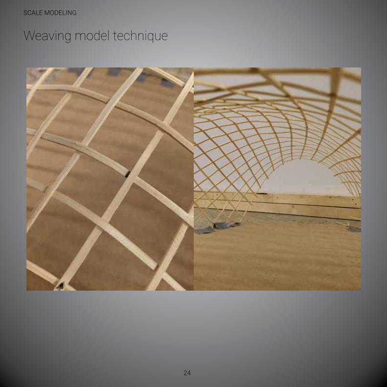
The far best modeling method is weaving. This is only possible with materials with some friction, such as wood or plywood. This tecnhique is the fastest, and it also allows rotation and some movement.
We learned this method from gridshell guru and leader of the research group gridshell.it, Sergio Pone.
Other techniques are not recommended, but the best alternative is to use rubberbands and tie a knot around every joint.
scale model techniques
StripsSlow and sti�
NeedlesSlow and sti�
Rubber bandsSlow but �exible
WeavningFast and �exible
SCALE MODELING
24
Weaving model technique

SCALE MODELING
25
Other modelling techniques
Rubberbands
Needles and screws


deFininG maTerial PrOPerTies

DEFINING MATERIAL PROPERTIES
28
EXPLAINATION
A key element is to find the correct cross-section. Larger cross-section (heigth) increases the strength, but decreases the
formability.
The important balance
Lath thickness
Formability
Strength

DEFINING MATERIAL PROPERTIES
29
Dimensioning cross section
48mm
21mm 21mm
23mm
23mm
Cross section
Dimensioning cross section
Area: 1104mm
Area: 966mm
eXPlainaTiOn
It is important to keep in mind that you remove parts of the cross-section when making holes for the bolts. Other girdshell projects uses clamps that removes this issue..
P: Carptenter Oak and woodland
DEFINING MATERIAL PROPERTIES
30
EXPLAINATION
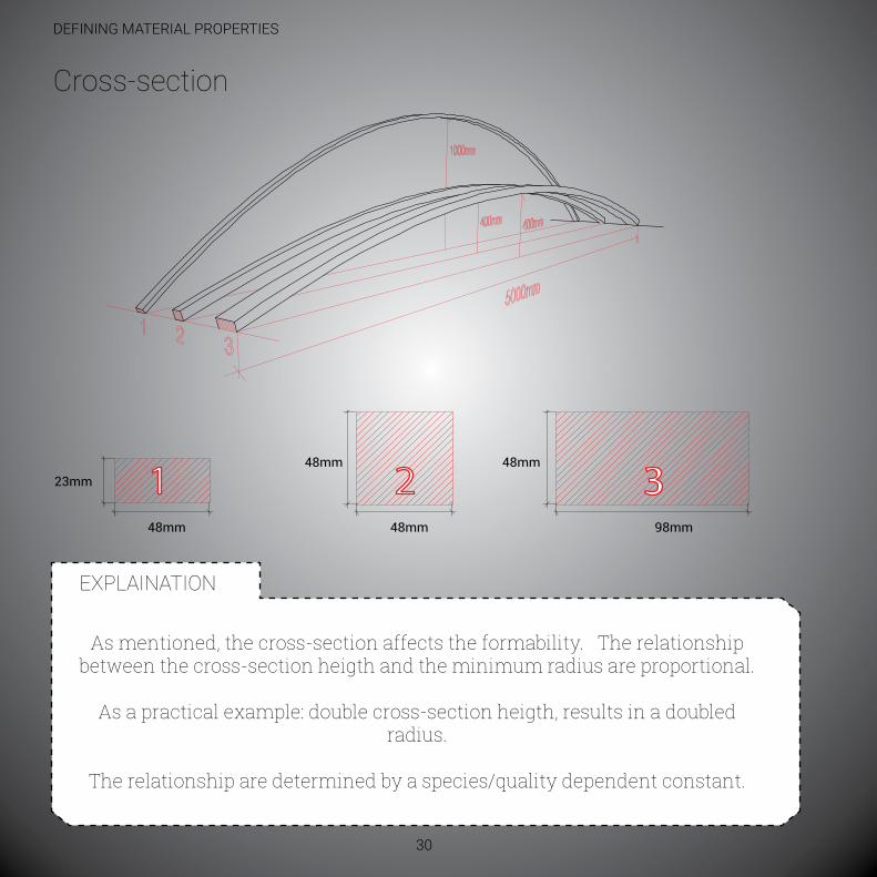
As mentioned, the cross-section affects the formability. The relationship between the cross-section heigth and the minimum radius are proportional.
As a practical example: double cross-section heigth, results in a doubled radius.
The relationship are determined by a species/quality dependent constant.
Cross-section
48mm 48mm
48mm 48mm
98mm
23mm 1 2 3

DEFINING MATERIAL PROPERTIES
31
EXPLAINATION
The first table examplifies that similar cross-sections with different timber-qualities results in different radiuses.The second table exemplifies that increasingly cross-section heigths results in larger radiuses.
The data (except the segment-lath) are extracted from Thomas Schiøtz Master Thesis, 2013. Data for the segment-lath was measured in a lab-test.
smallest curvature radius
different material constantsstrength class Constant Cross-section (h) smallest radiusC16 250 23 5750C24 229 23 5267C30 200 23 4600d30 167 23 3841d70 143 23 3289segment-lath 152 23 3496
different cross-sections strength class Constant Cross-section (h) smallest radiussegment-lath 152 12 1824segment-lath 152 24 3648segment-lath 152 48 7296
minRadius = Cross-section(h) * Con-
R
DEFINING MATERIAL PROPERTIES
32
EXPLAINATION
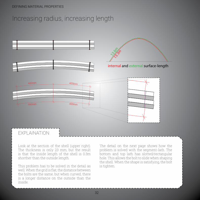
Look at the section of the shell (upper right). The thickness is only 23 mm, but the result is that the inside length of the shell is 0.3m shorther than the outside length.
This problem has to be solved in the detail as well. When the grid is flat, the distance between the bolts are the same, but when curved, there is a longer distance on the outside than the inside.
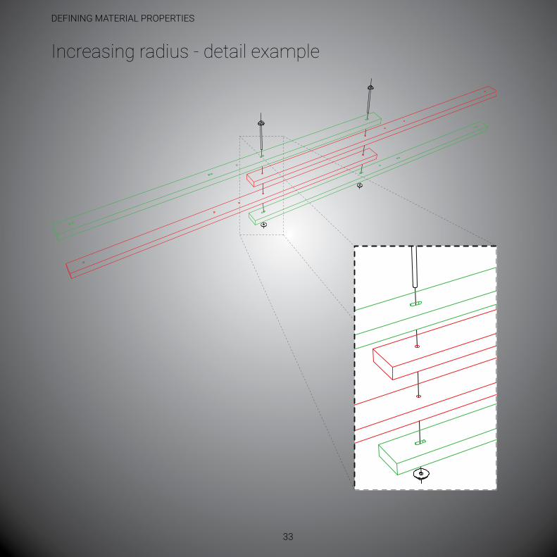
The detail on the next page shows how the problem is solved with the segment-lath. The bottom and top lath has slotted/rectangular hole. This allows the bolt to slide when shaping the shell. When the shape is satisfying, the bolt is tighten.
increasing radius, increasing length
internal and external surface-length
DEFINING MATERIAL PROPERTIES
33
Increasing radius - detail example

DEFINING MATERIAL PROPERTIES
34
eXPlainaTiOn
material characteristics in constructon timber
Bending strength e-module (n/mm2) (GPa)C16 16 8000C24 24 11000C30 30 12000d30 (oak) 30 10000d70 70 20000
density, wood species (kg/m3)
Balsa 200aspen 420spruce 430 Pine 490 Birch 580 Teak 630 Oak 650 Pokkenholt 1200
The most important characteristics to look for when choosing material is flexibility, formability and bending strength.
Table 1.Treteknisk Håndbok, Kapittel 2, http://www.engineeringtoolbox.com/wood-density-d_40.html
Table 2. Materialegenskaperfor konstruksjonstre, fra EN 338
material characteristics

DEFINING MATERIAL PROPERTIES
35
EXPLAINATION
The conditions the tree has grown in is important. If the forest is dense, it forces the tree to grow upwards instead creating many branches (knots). It is also said that slowly grown trees are stronger than fast grown.
Based on the timber mill`s experience, it is best to use the Sapwood (yteved):+ More elastic due to longer fibers+ Less knots– Not so moisture resistant
Choosing the best (part of the) tree
sap wood
hearth wood
Knots growing from the core, results in lesser occurance in the sapwood parts.
eXPlainaTiOn

DEFINING MATERIAL PROPERTIES
36
Wood species
Spruce
Pine
Birch
Oak
Aspen
soft, elastic, medium strength, easy to glue and paint, hard to impregnate.
soft, elastic, strong, durable, easy to cut and process, hard to glue and paint, can be impregnatet
ductile, elastic, low moisture resistance, easy to process,
dense, heavy, hard, durable, elastic, semi-hard to process, mosture resistant
Soft and loose, fluffing, moisture resistant (strongest dry), no cracking while drying
Characteristics of some species found in norwayTable from (Berge, 1992)

DEFINING MATERIAL PROPERTIES
37
EXPLAINATION
Wood species
Spruce Aspen
BirchPine
RedOakOak

hOW TO Build

How to build
40
EXPLAINATION
The saw-mill can often precut the timber to desired length. This is only recommended with well sorted timber with little knots.
An alternative is to precut piece by piece, removing the knots.
01: Precut

How to build
41
EXPLAINATION
02: Cutting holes
A cnc-mill cuts holes and slotted holes in the laths. 38 laths requires 15 minutes, including off/on-loading. This results in 2.5
laths/minute.
A tip is to create a jig that ensures easy unloading/loading, but still keeps the laths in place.

How to build
42
EXPLAINATION
03: element-assembly
Two laths with slotted holes, two laths with straight holes, one bolt, one nut and two washers creates the element prefabricated in the
workshop. The detailing makes the element very transport-friendly.

How to build
43
EXPLAINATION
04: The cross
The one cross is the base for the hole gridshell and represent the verticies in the grid.

How to build
44
EXPLAINATION
05: Grid-assembling
Weaving the crosses repeatedly, you can create what ever grid-shape you want.
The prefabricated holes maintains the correct grid-size.

How to build
45
EXPLAINATION
06: Grid-bed
When lifting the grid, it is important to distribute the forces as even as possible. A grid-bed, that replicates the shells final shape
ensures an even load distribution. The pallets underneath are progressively added.

How to build
46
EXPLAINATION
07: laying the grid
When laying the grid on the bed, it allows the builder to add crosses keeping a good working position.

How to build
47
EXPLAINATION
08: raising the structure
Larger structures would of course demand a crane, but low cost-structures can use primitive methods such as a temporary
scaffolding or a pallet jack.
Since a standard pallet jack only lifts 120mm and the pallet is 144mm, you need to bypass the load and do the lift in two stages.
01
03
02
04

How to build
48
EXPLAINATION
The foundations can be used both to shape and to secure the structure. Temporary columns and bracing
can also be sensible to add.
09: securing the grid

How to build
49
EXPLAINATION
10: Finnishing the shape
It is important to duplicate the digital shape in the real world. Positioning the foundations accurately can make it easier to find
the correct shape.

How to build
50
EXPLAINATION
11: Bracing
Bracing is important to lock the shape. This decreases the outwards force in the foundation and makes it more resistant to
un-eaven loads.
This also assures thattarp will not be disrupted by the bolts.

How to build
51
EXPLAINATION
12: Thighten the bolts
The last step is to thigten the bolts. This joins the laths and makes the structure stronger.

How to build
52
EXPLAINATION
Others: Extending the laths
eXPlainaTiOn
The Gridshell.it team uses a detail where they extend the laths for each fifth grid-lenght.
Our solution, shown earlier, has been developed from this solution, but instead of having the extending as a exception, our detail use it as a design-rule. This makes the pattern easier, more dynamic and more homogenious.

How to build
53
eXPlainaTiOn
This example is from the building of the Savill garden gridshell. In order to produce knot-free, continious laths up to 36 meters, every piece was cleand free from knots by cutting them into 300mm to 900mm lengths. They were thereafter fingerjoint to 6m laths at the workshop and then lap joint to its final lenght at the building site.
Others: Extending the laths
Knots in material
6m laths lap joints 36m laths
300-900mm pieces �ngerjoints
P: David Baugh

How to build
54
EXPLAINATION
Kurvatur = TverrsnittsøgdKonstant
Untempost qui tenimin ihitium quae. Tecus, sim aliam at lam sit faccatur, cum autatum ipis erumqui tempore rerovitae. Nemporum aboresequi dolloru ptatatur audita dolupiciatem aut quodis sim que veliqui tem eossunda pra exere.
Que nis dolest, int idem que id quo quia pra dolest, int idem que id quo quinum
eXPlainaTiOn
shear blocks
Shear blocks through weaving
Same height blocks Taller blocks makes an I-pro�le-like strength
Plain grid has little shear sti�ness
To reduce the “span” of each lath, shear blocks are added.They provide shear stiffnes to the grid, and could also help making
a distance between the top and bottom layer, to create a taller cross-section.

How to build
55
eXPlainaTiOn
diagonal bracing
Diagonal laths Diagonal wires
Little in plane sti�ness without triangulation
(plywood) plates
The plain grid has initially no stiffness in its plane. In order to lock the quadrants, it needs to be triangulated.
Triangulating the whole grid is not necessarily needed , and it can be done in different ways.

BudGeT

BUDGET
58
FInAnCIAl (A DRAFT!)
material Quantity unit price PriceTimber 2034 m 6.25 nOK 12 712 nOKBolts/nuts 2825 stk 3.00 nOK 8475 nOKTarpolin 131.5 m2 200 nOK 26 300 nOKProduction 40 t 750 nOK 30 000 nOKassembling 60 t 500 nOK 30 000 nOK TOTAl: ≈108 000 nOK Price pr m2 ≈820 nOK
The materials listet are from the built example, 132 m2. it is important to keep in mind that foundations, tools and unknown costs will be added to a permanent project. Production/assembling can decrease if more industrialized.The master-thesis` built project were due to kind sponsors almost free.
59
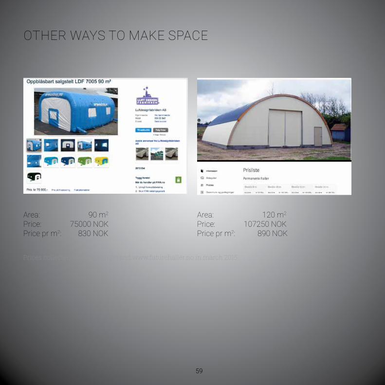
OTher WaYs TO maKe sPaCe
area: 90 m2 Price: 75000 nOKPrice pr m2: 830 nOK
Prices collected at www.finn.no and www.futurehaller.no in march 2015.
area: 120 m2 Price: 107250 nOKPrice pr m2: 890 nOK


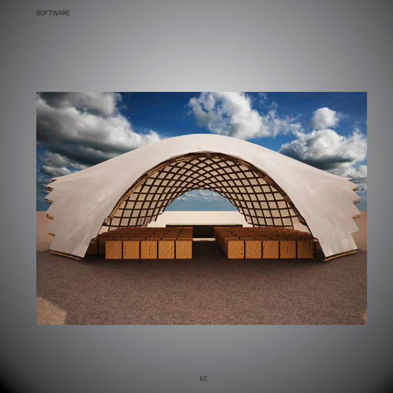
sOFTWare

SOFTWARE
62
CROSS SECTION
Define Grid & Material1
DefineGrid-shape2
DefineAnchor-points3
Form-finding simulation4
Shape/Curvature-analysis
FEM-analysis
DONE!
OK! ERROR!
OK! ERROR!
Shap
eAn
alys
e1 Define Grid & Material 2 Define grid-shape
3 Define foundations 4 Form-finding
5 Shape/curvature analysis 6 FEM-analysis
Choose a diagonal or orthogonal grid. Also choose the grid-size.
Cross -section and material-quality are also to be choosed, but can easily be changed later.
Draw a closed curve that defines the grid-shape.
Keep it simple! It is wise to choose either 45° or 90° corners
The principle is to choose wich points are to be foundations. These are then connected to a curve that the points should be attached to. This is the foundation.
The software has four foundations, but can easily be expanded
The shape is generated based on foundations and forces.Gravity: The gravity is set up-side down.Bending-force: Like a beam, the lines tries to resist bending. Spring: Each segment is defined as a strong spring.
Analysis is next when shape is generated. First aestetically and functional. Graphical displays shows if some of the parts will break or some area is to0 flat.
If the shape is not approved, point 1,2 or 3 has to be adjusted.
A software called Karamba makes it possible to do FEM-analasys. This enables the user to add snow- and other loads on the structure. Results as deplacement and forces in the anchor-point can determine if the shape is buildable. If the shape is not approved, point 1,2 or 3 has to be adjusted.

SOFTWARE
63
Define Grid & Material1
DefineGrid-shape2
DefineAnchor-points3
Form-finding simulation4
Shape/Curvature-analysis
FEM-analysis
DONE!
OK! ERROR!
OK! ERROR!
Shap
eAn
alys
e
1 Define Grid & Material 2 Define grid-shape
3 Define foundations 4 Form-finding
5 Shape/curvature analysis 6 FEM-analysis
Choose a diagonal or orthogonal grid. Also choose the grid-size.
Cross -section and material-quality are also to be choosed, but can easily be changed later.
Draw a closed curve that defines the grid-shape.
Keep it simple! It is wise to choose either 45° or 90° corners
The principle is to choose wich points are to be foundations. These are then connected to a curve that the points should be attached to. This is the foundation.
The software has four foundations, but can easily be expanded
The shape is generated based on foundations and forces.Gravity: The gravity is set up-side down.Bending-force: Like a beam, the lines tries to resist bending. Spring: Each segment is defined as a strong spring.
Analysis is next when shape is generated. First aestetically and functional. Graphical displays shows if some of the parts will break or some area is to0 flat.
If the shape is not approved, point 1,2 or 3 has to be adjusted.
A software called Karamba makes it possible to do FEM-analasys. This enables the user to add snow- and other loads on the structure. Results as deplacement and forces in the anchor-point can determine if the shape is buildable. If the shape is not approved, point 1,2 or 3 has to be adjusted.

SOFTWARE
64
software-list
The form-finding and analysis can be done in several different ways and with different softwares. Following are the softwares and purposes used in this thesis.
rhinoceros 3drhinoceros is the 3d-software that functions as a base for the geometry. This software is also used when manufacturing the elements.
GrasshopperGrasshopper is a plugin for rhino. This is a graphical programming language aimed for parametric modelling. Geometry is generated based on a large algorithm.
KangarooKangaroo is a plug-in for Grasshopper that enables grasshopper to add physics on the 3d. Kangaroo is responsible for the form-finding process.
KarambaKaramba is a plug-in for Grasshopper that does analysis on a given structure. The plug-in adds material-properties and exports results like deplacement and reaction-forces.
SOFTWARE
65


OTher Gridshells

OTHER GRIDSHELLS
68
PrOPerTies
Material:Material-dim:Total span:Grid-size:JointBrazing
Function:Architect:Year:Weigth:Mat.Volume:
Larch20x50mm10x10m500x500mmM6 Bolt+washerTimber
EksperimentGridshell.it20147kg/m22m3
Toledo 2.0, italy

OTHER GRIDSHELLS
69
PrOPerTies
downland gridshell, england
Material:Material-dim:Total span:Grid-size:JointBrazing
Function:Architect:Year:Price:
Oak50x35mm50x12,5/16m500x500,1000x1000mm4stk M8 Bolt+ bracketsTimber
MuseumEdward Cullian; 20021097Pund/m2

OTHER GRIDSHELLS
70
mannheim multihalle, Germany
PrOPerTies
Material:Material-dim:Area:Grid-size:JointBrazing
Function:Architect:Year:
Swimming pool, restaurantFreiOtto, OveArup++1972
Hemlokk Pine50x50mm9500m2
500x500mm M8 Bolt, washerSteel-wire
P: Oliver Lowenstein

OTHER GRIDSHELLS
71
savill Garden, england
PrOPerTies
Material:Material-dim:Total span:Grid-size:Brazing
Function:Architect:
Year:Timber length:
Larch(Quality1&2)80x50mm2250m21200x1200mmPlywood
Visitor centreGlennHowells,BuroHappold200520000m
P: David Baugh

shell you later.