Embed Size (px)
Citation preview

Greenwich Academic Literature Archive (GALA)– the University of Greenwich open access repository
http://gala.gre.ac.uk
__________________________________________________________________________________________
Citation:
Yin, Chunyan (2006) Experimental and modelling analysis on the performance of anisotropic conductive films as used in electronics packaging. PhD thesis, University of Greenwich.
__________________________________________________________________________________________
Please note that the full text version provided on GALA is the final published version awarded
by the university. “I certify that this work has not been accepted in substance for any degree,
and is not concurrently being submitted for any degree other than that of (name of research
degree) being studied at the University of Greenwich. I also declare that this work is the result
of my own investigations except where otherwise identified by references and that I have not
plagiarised the work of others”.
Yin, Chunyan (2006) Experimental and modelling analysis on the performance of anisotropic
conductive films as used in electronics packaging. ##thesis _type## , ##institution##
Available at: http://gala.gre.ac.uk/6355/
__________________________________________________________________________________________
Contact: [email protected]

EXPERIMENTAL AND MODELLING ANALYSIS
ON THE PERFORMANCE OF ANISOTROPIC
CONDUCTIVE FILMS AS USED IN
ELECTRONICS PACKAGING
by
Chunyan Yin
Centre for Numerical Modelling and Process Analysis, School of Computing and Mathematical Sciences, the University of Greenwich,
London, U.K.
THESES
s %
A thesis submitted in partial fulfilment of the requirements of the University of Greenwich for the Degree of Doctor of Philosophy
November 2006

Declaration
/ certify that this work has not been accepted in substance for any degree, and is
not concurrently submitted for any degree other than that of Doctor of Philosophy
(Ph.D.) of the University of Greenwich. I also declare that this work is the result of my
own investigations except where otherwise stated.
Chunyan Yin
Prof. Chris Bailey (Supervisor)
Dr. Hua Lu (Supervisor)
Abstract
Abstract
The aim of this research is to understand the failure modes and mechanisms of
adhesive materials used to flip-chip bond a silicon die onto a polyimide substrate. The
bonding material investigated in this research is called Anisotropic Conductive Film
(ACF). This is a promising interconnection material and has gained extensive interest
in the electronics packaging industry.
Both experimental and finite element analysis (FEA) methods were used in order to
investigate the behaviour of the ACF materials when subjected to certain
manufacturing and environmental testing conditions. The manufacturing condition
investigated was a subsequent solder reflow process on an ACF flip-chip bonded
device. The environmental testing condition investigated was the moisture test.
For the manufacturing condition, both experimental and modelling results
demonstrate the impact of a subsequent reflow process on the behaviour of the ACF
joint. Typical failures observed after this process were cracks at the pad/particle
interface. This failure mode was more severe with a higher peak reflow temperature.
This was also found using FEA where high tensile stresses were predicted in these
regions. FEA modelling was also used to help identify the mechanisms leading to these
failures. This is primarily due to the Coefficient of Thermal Expansion (CTE) miss-
match in the materials and the elastic/plastic deformation behaviour of the conductive
particle. Important design variables that can minimise these failures are the Young's
Modulus and CTE of the adhesive and the height of the bump on the die.
For the environmental testing condition, an autoclave test at 121°C, 100%RH and
pressure of 2atm was used. More than 85% of the ACF joints failed during the first 24
hours of testing. The failure mode observed was cracking along the interface between
the adhesive and substrate and pad. A macro-micro modelling approach was used to
help identify the mechanisms leading to these failures. It was found that most of the
damage is caused by moisture diffusion and associated swelling. Important design
variables that will help minimise this mode of failure are: Coefficient of Moisture
Expansion (CME) and Young's Modulus of the adhesive and the height of the bump
on the die.
I

Acknowledgments
Acknowledgments
I would like to sincerely thank both of my supervisors, Prof. Chris Bailey and Dr.
Hua Lu for their supervision, guidance and encouragement during each stage of my
study. Also I would like to thank all my colleagues at the University of Greenwich
who have given me advices and shown the interests to my research.
I would like to express my deep gratitude to Prof. Yan-Cheong Chan within the
Department of Electronic Engineering at City University of Hong Kong for initiating
this joint Ph.D. program and all the support offered throughout my study. I would like
to thank my colleagues at City University of Hong Kong for the support in the
experimental work and in particular, Ms Sai Choo Tan, for her time and kind
assistance for the work conducted at EPA Centre.
I would like to thank my parents for their encouragement through my Ph.D. study.
My husband, Mr Guangbin Dou who is pursuing his Ph.D. at Loughborough
University is deserved to be appreciated for his support and understanding, during the
last ten years, we have been studying side by side all the time.
Finally, I would like to acknowledge the University of Greenwich and City
University of Hong Kong for the financial support to undertake this research.
II

Table of Contents
Table of Contents
ABSTRACT............................................................................................................................I
ACKNOWLEDGMENTS.................................................................................................. II
TABLE OF CONTENTS...................................................................................................III
LIST OF FIGURES.......................................................................^
LIST OF TABLES...........................................
GLOSSARY .....................................................................................................................XIV
CHAPTER 1: INTRODUCTION....................................................................................... 1
1.1 Background....................................................................................................................... 1
1.2 Aims and Objectives of This Research............................................................................ 4
1.3 Layout of This Thesis....................................................................................................... 6
1.4 Original Techniques and Findings................................................................................... 7
CHAPTER 2: LITERATURE REVIEW.......................................................................... 9
2.1 Experimental Studies........................................................................................................ 9
2.1.1 ACA Materials......................................................................................................... 9
2.1.2 Curing Methods and Bonding Parameters............................................................ 14
2.1.3 Environmental Testing.......................................................................................... 16
2.2 Computer Modelling ...................................................................................................... 18
2.2.1 Flow Analysis of Bonding Process....................................................................... 19
2.2.2 Mechanical and Electrical Behaviour of Conductive Particles............................ 23
2.2.3 Moisture Absorption and Induced stresses........................................................... 27
2.3 Summary......................................................................................................................... 30
CHAPTER 3: FLIP CHIP TECHNOLOGY.................................................................. 31
m

Table of Contents
3.1 Introduction...............................................................................................................-..-^!
3.21C Assembly Technologies ............................................................................................ 33
3.2.1 Wirebonding.......................................................................................................... 33
3.2.2 Tape Automated Bonding (TAB).........................................................................- 34
3.2.3 Flip Chip ................................................................................................................35
3.3 Materials Used for Interconnections.............................................................................. 36
3.3.1 Solder Alloys .........................................................................................................37
3.3.1.1 Tin-Lead Solder.....................................................................................................^?
3.3.1.2 Lead-Free Solder...................................................................................................37
3.3.2 Electrically Conductive Adhesives (EGAs).......................................................... 40
3.3.2.1 Isotropic Conductive Adhesives (ICAs)................................................................40
3.3.2.2 Anisotropic Conductive Adhesives (ACAs).......................................................... 42
3.3.2.3 Non Conductive Adhesives (NCAs)......................................................................43
3.4 Reliability Testing ..........................................................................................................44
3.4.1 Reliability and Failure........................................................................................... 44
3.4.2 Reliability Test and Standard................................................................................ 45
3.4.2.1 Non-Accelerated Test.............................................................................................45
3.4.2.2 Accelerated Test.....................................................................................................46
3.4.3 Failure Models....................................................................................................... 47
3.5 Applications of ACF Flip Chips..................................................................................... 47
3.5.1 Liquid Crystal Display........................................................................................... 48
3.5.2 Disk Drive.............................................................................................................. 49
3.5.3 Limitations for Further Applications .................................................................... 50
3.6 Summary......................................................................................................................... 51
CHAPTER 4: RELIABILITY OF ACFS FOR FLIP CHIP ON FLEX APPLICATIONS: AN EXPERIMENTAL STUDY...................................................... 53
4.1 Introduction..................................................................................................................... 53
4.2 Experimental Design...................................................................................................... 56
4.2.1 Materials................................................................................................................. 57
IV

Table of Contents
4.2.1.1 Silicon Die................................................................................................... .--58
4.2.1.2 Flexible Substrates............................................................................................58
4.2.1.3 Anisotropic Conductive Film (ACF)..................................................................-..59
4.2.2 Flip Chip Bonding Process..................................................................... ......... 62
4.2.3 Joint Resistance Measurement.............................................................................. 65
4.3 Results and Discussion................................................................................................... 66
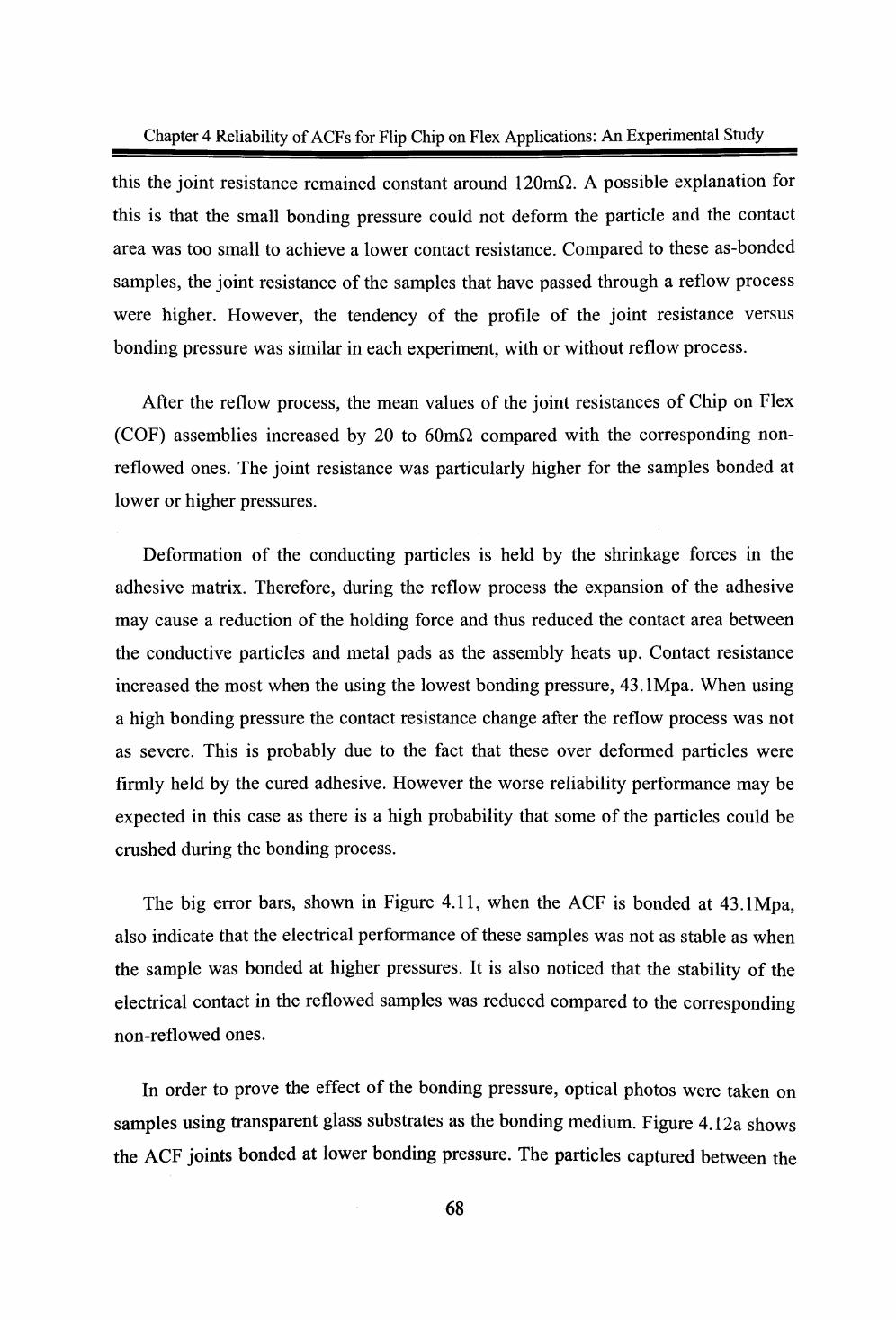
4.3.1 Bonding Conditions............................................................................... ............. 67
4.3.1.1 Bonding Pressure.................................................................................................... 67
4.3.1.2 Bonding Temperature................................................................................... .... 70
4.3.1.3 Bonding Time.......................................................................................................71
4.3.2 DSC Test Results................................................................................................... 72
4.3.3 Reliability Tests..................................................................................................... 75
4.3.3.1 Joint Resistances and Failure Rate.........................................................................76
4.3.3.2 Scanning Electron Microscope (SEM) Photos...................................................... 78
4.3.3.3 Effect of Solder Reflow..........................................................................................81
4.4 Conclusions..................................................................................................................... 83
CHAPTER 5: MODELLING OF THE EFFECT OF SOLDER REFLOW ON ACF PERFORMANCE..............................................................................................................^
5.1 Computational Modelling............................................................................................... 85
5.1.1 Geometry and Mesh Model................................................................................... 86
5.1.2 Modelling Assumptions......................................................................................... 88
5.1.3 Modelling Results.................................................................................................. 89
5.1.4 Parametric Study.................................................................................................... 91
5.1.4.1 Effect of the CTE of the Adhesive Matrix.............................................................91
5.1.4.2 Effect of the Young's Modulus of the Adhesive Matrix.......................................92
5.1.4.3 Effect of the Bump Height.....................................................................................93
5.2 Sensitivity Analysis........................................................................................................ 96
5.2.1 Scaled and Un-scaled Design Points..................................................................... 97
5.2.2 Sensitivity Test Results ....................................................................................... 100
V

Table of Contents
5.3 Impact of Moving From Lead to Lead Free Soldering............ .......................... 101
5.4 Conclusions...................................................................................................... .--- 105
CHAPTER 6: HYGRO-MECHANICAL ANALYSIS OF AN ACF ASSEMBLY IN AUTOCLAVE TEST....................................................................................................... 106
6.1 Introduction................................................................................................................... 107
6.2 Computer Modelling Technique.................................................................................. 107
6.2.1 Challenges in Modelling the ACF Assembly......................... ......................... 108
6.2.2 Macro-Micro Modelling Technique.................................................................... 108
6.2.3 Interpolation of the Displacement Fields............................................................ 110
6.3 Demonstration of the Macro-Micro Modelling Technique......................................... 113
6.3.1 Geometry and FE Models.................................................................................... 113
6.3.2 Material Properties............................................................................................... 116
6.3.3 Modelling Results and Error Analysis................................................................ 116
6.4 Moisture Diffusion Prediction...................................................................................... 120
6.4.1 Conservation Equation in PHYSICA.................................................................. 120
6.4.2 Wetness Fraction Approach................................................................................ 121
6.4.3 Test Case: One Dimensional Moisture Diffusion............................................... 124
6.5 Modelling Analysis of an ACF flip chip Assembly.................................................... 127
6.5.1 Geometry and Mesh Model................................................................................. 127
6.5.2 Material Properties and Modelling Assumptions............................................... 129
6.5.3 Modelling Results................................................................................................ 130
6.5.3.1 Moisture Diffusion............................................................................................... 130
6.5.3.2 Moisture Induced Stress....................................................................................... 133
6.5.3.3 Temperature Induced Stresses ............................................................................. 136
6.5.4 Parametric Analysis............................................................................................. 137
6.5.4.1. Effect of the CME of the Adhesive Matrix........................................................ 138
6.5.4.2. Effect of the Young's Modulus of the Adhesive Matrix.................................... 139
6.5.4.3. Effect of the Bump Height.................................................................................. 140
6.6 Failure Mechanisms...................................................................................................... 141
VI
Table of Contents
<5.7 Conclusions................................................................................................................... 142
( CHAPTER 7: CONCLUSIONS AND FURTHER WORK........................................ 144
7.1 Conclusions................................................................................................................... 144
7.2 Further Work................................................................................................................. 146
7.2.1 Experiments......................................................................................................... 147
7.2.2 Computational Modelling....................................................................................147
7.2.3 Future Challenges with ACAs............................................................................. 148
APPENDICES...................................^
A. Differential Equation of Diffusion................................................................................ 149
B. Material Behaviours....................................................................................................... 152
B.I Elasticity................................................................................................................. 153
B.2 Plasticity................................................................................................................. 153
B.3 Rate Dependent Material Behaviour..................................................................... 154
C. Finite Element Method (FEM)......................................................................................155
C.I Linear Elasticity..................................................................................................... 157
C.I.I Equilibrium Equations............................................................................................ 157
C.1.2 Discretization of Solution Domain......................................................................... 160
C.1.3 Discretization of Equilibrium Equations................................................................ 164
C.1.4 Solution Procedure.................................................................................................. 167
C.2 Elasto Visco-Plasticity........................................................................................... 168
C.2.1 Elasto-Viscoplasticity Material Model.................................................................. 168
C.2.2 Three Dimensional Elasto-Viscoplastic Model..................................................... 170
C.2.3 A Newon-Raphson-Based Iteration Method.......................................................... 172
D. PHYSICA - A Simulation Tool.................................................................................... 175
E. Liquid Crystal Display: A Case Study Using PHYSICA............................................ 176
E.I Problem Description............................................................................................... 178
E.2 Geometry and Computational Mesh...................................................................... 178
E.3 Boundary Conditions and Material Properties...................................................... 180
VII

REFERENCES................................................................................................................. 185

List of Figures

List of Figures

ssssssssssasas


List of Tables

Glossary
ACA
ACF
ACP
AMLCD
EGA
CAD
CFD
COF
COG
CRT's
CTE
CME
DC
DOE
DSC
ECA
ELV
FCOF
FEA
FEM
FPC
FPP
FTIR
FV
HDD

1C
ICA
I/O
ITO
LCD
LCP
NCA
PCB
PCX
PEN
PET
RH
RS
RoHS
SAC
SEM
SMT
TAB
Tg
2D
3D
UBM
VFMW
WEEE

Chapter 1
Introduction
1.1 Background

Wafer
Electronic Package Hierarchy
I Pint level package (Single chip Module)
First level package (Multichip Module)
Second level
(PCB or Card)
Third level package (Mother board)


1.2 Aims and Objectives of This Research


1.3 Layout of This Thesis

1.4 Original Techniques and Findings

8

Chapter 2
Literature Review
2.1 Experimental Studies
2.1.1 ACA Materials


=SS=SS=9SS5=S=SS


2.1.2 Curing Methods and Bonding Parameters
14

=s^=s=a^=^s=

0.7
3 0.3 'Jn ^^
'C
0.1 10 log Time, hour
100 1000


sssssssss^ssssssssss

>«+3


^5=^^==^=^=
22


30 i ( )
1=0 04s t=131$ t=1048«


60 40 Deform%
(a)
80 60 40 Deform%
(b)

& Cf &
<r (ftC)


95Pb5Sn
90PblOSn
308
275
312
302


DDDQQDDDQGD D D


-\


Chapter 5 Modelling of the Effect of Solder Reflow on ACF Performance
Chapter 5
Modelling of the Effect of Solder Reflow on ACF Performance
Experimental studies in Chapter 4 revealed that the solder reflow process had a
substantial effect on the electrical and reliability performance of ACF flip chip
assemblies. The change from tin-lead solder to lead-free solder results in an extra 20-
50°C increase in the reflow peak temperature. This could damage the flip-chip
assembly and the ACF materials. In this Chapter, the performance of ACF assemblies
is further studied using computer modelling techniques. A parametric analysis
investigates the impact of adhesive material properties (CTE and Young's modulus)
and geometrical height of the bump (or pad on the silicon die). This analysis shows
that the CTE of the adhesive matrix is proved the most important design variable in
minimising the damage in the assembly when sUbjected to higher reflow temperatures.
These modelling results are compared with the experimental findings in Chapter 4.
5.1 Computational Modelling
The software package PHYSICA was employed to investigate the primary cause of
the failures observed in the experiments. This work focused on modelling the
thermally induced stress in the ACF joints as they passed through the solder reflow
process.
85


MODEL: OCT28- DEFORMATION - 15 CASEI: PHYSICA RESULTS STEP: 10 TIME: 200 NODAL STRESS YY MAX .177E9 HIN = -.I18E9
MODEL: OCT28- OEFORMATION > 15 CASE I: PHYSICA RESL STEP: 10 TIME: 200 NODAL STRESS YY MAX .177E9 HIN = -.118E9
15E9124E9966E8698E8429E816E8
-.109E8-.378E8-.647E8-.91EE8
MODEL: ocT2e-CftSEl: PHYSICS RESULTS STEP: 19 TIME: 2BO NODAL EVPSTR MAX - .22E-1 MIN - 0


cfyy


12
3
4
5
6
7
8
9
10
11
12
13
14
15
Lower bound
Higher bound
Design variables
Young's modulus (MPa)
2400
2400
2400
2400
800
800
800
800
2400
800
1600
1600
1600
1600
1600
800
2400
CTEof adhesive (ppm/°C)
163
163
103
103
163
163
103
103
133
133
163
103
133
133
133
103
163
Bump height (urn)
12
4
12
4
12
4
12
4
8
8
8
8
12
4
8
4
12
Stress (MPa)
270
243
128
109
419
375
198
162
183
281
307
138
242
213
222


425
400
373 ]
8 350
w 300v>2 275
2 250
t; 225
u 200
* 175
150
125
100
s
100 125 150 175 200 225 250 275 300 325 350 375 400 425


Chapter 6 Hygro-Mechanical Analysis of an ACF Assembly in Autoclave Test
6.1 Introduction
Moisture is one of the most important factors that can affect the reliability of ACF
components. Previous studies have revealed that the reliability of ACF components is
strongly affected by moisture, which is predominantly considered as the most
important factor of ACF component failures [8][9][10][11][12][13].
Previous modelling work [10][11][12] has been mostly limited to the analysis of
simplified 2D models. Three dimensional models have focused on the micro-domain
and ignored the global effects at package level, or they have modelled the whole
package and used gross assumptions at the micro interconnect level [48][49][61][62].
The recognised difficulty here is that due to the vast range of length-scales in an ACF
flip chip assembly, and the large number of conductive particles, an 'exact' model
which includes all the particles and interconnections is simply not achievable with
today's computer technology.
In this study, a 3D macro-micro modelling method is used to overcome the
difficulty caused by the multi-length-scale nature of this problem and to enable a more
detailed 3D representation and analysis of an ACF flip chip assembly. Two models:
the macro and micro models, with different mesh sizes were built. The macro model
was used to predict the overall behaviour of the whole package under moisture
conditions. The displacement obtained from this global model was then used to set the
boundary condition of the micro model so that the detailed stress analysis in the region
around the conductive particle and between the pads can be undertaken.
6.2 Computer Modelling Technique
The experimental work presented in Chapter 4 proved that moisture absorption had
a large effect on the reliability perfonnance of ACF interconnections. In order to better
understand the role that moisture plays on the reliability perfonnance of ACF
lO7


Chapter 6 Hygro-Mechanical Analysis of an ACF Assembly in Autoclave Test
The boundary conditions applied to the local model can be obtained from the
global solution with interpolation. Due to the difference in mesh refinement in the
local region, there is a violation in equilibrium at the global/local boundary which can
be eliminated with global/local iteration. However, in engineering practice, the initial
global solution is often assumed to be accurate enough and no iteration is performed
[104], therefore the present study assumes such engineering procedure.
Sub-modelling is based on St. Venant's principle, which states that if a system of
forces acting on a small region of a body is replaced by a different but statically
equivalent system of forces acting on the same region, then such a replacement does
not cause significant changes in the predicted stresses and displacements at points in
the body remote from the region concerned [l 05][ 106]. It also implies that if the
boundaries of the sub-model are far enough away from the stress concentration,
reasonably accurate results can be calculated in the sub-model. This is the case with
the sub-models used in the following analysis where the stress concentrations are
located around the conductive particles.
The procedure for a macro-micro modelling analysis consists of the following four
steps:
( I) Create the Global and Local Models: the global mesh refers to the mesh that
models the entire structure. The local mesh refers to the mesh that models the
local area of interest and is a more detailed mesh, designed to capture the local
stress/strain variations.
(2) Solve the Global Model: the global model is solved and the displacement
results will be used to set up the boundary conditions for the micro model.
(3) Interpolation between the Models: Interpolation of displacements from the
global solution along the boundary of the local area in the global mesh is made
in this step. The interpolation of data from the global mesh is necessary
109


= 8l + 82X3


-t s\/\


^-
MODEL: HCE ANALYSIS: PHYSIC*


ASSEHBLY: CLBAL DEFORMATION * 400CftSEI: PHYSICA RESULTSSTEP: i TIME: .i«<E6NODAL ESTRES

MODEL: AACASEl: PHYSIC* RESULTSSTEP: i line: .86<E5NOOAL ESTRES MAX .127E4 HIM - 8.8
-L,
Il93(174
159143126
J112196.7181.1IBS.EIso
HOOEL: AACASEI: PHYSICA RESULTS STEP: 1 TIME: .864E5 NODAL STRESS ZZ NAX/HIN ON MODEL SET: BAX = 698 HIN ' -3. 19
MODEL: AnCASEI: PHYSICA RESUL STEP: 1 TIME: .864E5 NODAL STRESS ZZ MAX/MIN ON HOOEL SET:


MODEL: ftrtCrtSEl: PHYSICft RESULTS STEP: 1 TIME: .864E5 NOOftL STRESS ZZnnx/MiN ON MODEL SET:RAX = 12.3 MIN - -127
MODEL: rtftCrtSEl: PHYSICS RESULTSSTEP: 1 TIME: .864E5NODAL STRESS ZZMAX/MIN ON MODEL SET:MAX ' 12.3MIN * -127


OX

dF r)F


e


ST (~*


CO Q^
V)
CO
MODEL: MCEC«SEU PHYSIC* RESULTSSTEP: i TIME: leeeeeoNOOHL STRESS XZMAX - 2391303MIN > -2089600