Embed Size (px)
Citation preview
edizione - edition85
ALI4
06/2012
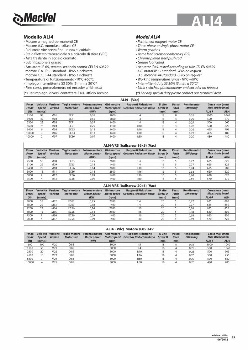
Modello ALI4• Motore a magneti permanenti CE• Motore A.C. monofase-trifase CE• Riduttore vite senza fine - ruota elicoidale• Stelo filettato trapezoidale o a ricircolo di sfere (VRS)• Asta traslante in acciaio cromato• Lubrificazione a grasso• Attuatore IP 65, testato secondo norma CEI EN 60529 motore C.A. IP55 standard - IP65 a richiesta motore C.C. IP44 standard - IP65 a richiesta• Temperatura di funzionamento -10°C +60°C• Impiego intermittente S3 30% (5 min) a 30°C*• Fine corsa, potenziometro ed encoder a richiesta(*) Per impieghi diversi contattare il Ns. Ufficio Tecnico
Model ALI4• Permanent magnet motor CE• Three phase or single phase motor CE• Worm gearbox• Acme lead screw or ballscrew (VRS)• Chrome plated steel push rod• Grease lubricated• Actuator IP65, tested according to rule CEI EN 60529 A.C. motor IP 55 standard - IP65 on request D.C. motor IP 44 standard - IP65 on request• Working temperature range -10°C +60°C• Intermittent duty S3 30% (5 min) a 30°C*• Limit switches, potentiometer and encoder on request(*) For any special duty please contact our technical dept.
ALI4 - (Vac) FmaxFmax
VelocitàSpeed
VersioneVersion
Taglia motoreMotor size
Potenza motoreMotor power
Giri motoreMotor speed
Rapporti RiduzioneGearbox Reduction Ratio
D viteScrew D
PassoPitch
RendimentoEfficiency
Corsa max (mm)Max stroke [mm]
(N) (mm/s) (KW) (rpm) (mm) (mm) ALI4-F ALI42100 93 M01 IEC71 0,55 2800 1.4 18 8 0,31 1000 10403900 47 M02 IEC71 0,55 2800 1.4 18 4 0,29 500 7705300 23 M03 IEC71 0,37 1400 1.4 18 4 0,29 500 6608600 9 M04 IEC71 0,25 1400 1:10 18 4 0,28 500 5209400 6 M05 IEC63 0,18 1400 1:16 18 4 0,26 495 495
10000 3 M06 IEC63 0,13 1400 1:30 18 4 0,22 485 48510000 2 M07 IEC56 0,09 1400 1:50 18 4 0,20 480 480
ALI4-VRS (ballscrew 16x5) (Vac) FmaxFmax
VelocitàSpeed
VersioneVersion
Taglia motoreMotor size
Potenza motoreMotor power
Giri motoreMotor speed
Rapporti RiduzioneGearbox Reduction Ratio
D viteScrew D
PassoPitch
RendimentoEfficiency
Corsa max (mm)Max stroke [mm]
(N) (mm/s) (KW) (rpm) (mm) (mm) ALI4-F ALI42500 58 M08 IEC63 0,25 2800 1.4 16 5 0,77 625 8253100 29 M09 IEC63 0,18 1400 1.4 16 5 0,77 625 8253400 23 M10 IEC56 0,14 2800 1:10 16 5 0,74 625 7805000 15 M11 IEC56 0,14 2800 1:16 16 5 0,38 620 6206000 7 M12 IEC56 0,09 1400 1:16 16 5 0,68 620 6207500 4 M13 IEC56 0,09 1400 1:30 16 5 0,59 570 570
ALI4 (Vdc) Motore D.85 24VFmaxFmax
VelocitàSpeed
VersioneVersion
Taglia motoreMotor size
Potenza motoreMotor power
Giri motoreMotor speed
Rapporti RiduzioneGearbox Reduction Ratio
D viteScrew D
PassoPitch
RendimentoEfficiency
Corsa max (mm)Max stroke [mm]
(N) (mm/s) (KW) (rpm) (mm) (mm) ALI4-F ALI4600 100 M20 D.85 3000 1.4 18 8 0,31 1000 1040
1100 50 M21 D.85 3000 1.4 18 4 0,29 500 10402800 20 M22 D.85 3000 1:10 18 4 0,28 500 9054100 13 M23 D.85 3000 1:16 18 4 0,26 500 7506800 7 M24 D.85 3000 1:30 18 4 0,22 500 580
10000 4 M25 D.85 3000 1:50 18 4 0,20 480 480
ALI4-VRS (ballscrew 20x5) (Vac) FmaxFmax
VelocitàSpeed
VersioneVersion
Taglia motoreMotor size
Potenza motoreMotor power
Giri motoreMotor speed
Rapporti RiduzioneGearbox Reduction Ratio
D viteScrew D
PassoPitch
RendimentoEfficiency
Corsa max (mm)Max stroke [mm]
(N) (mm/s) (KW) (rpm) (mm) (mm) ALI4-F ALI43000 58 M32 IEC63 0,25 2800 1.4 20 5 0,77 625 8803800 29 M33 IEC63 0,18 1400 1.4 20 5 0,77 625 8504200 23 M34 IEC56 0,14 2800 1:10 20 5 0,74 625 8506000 15 M35 IEC56 0,14 2800 1:16 20 5 0,38 620 8007500 7 M36 IEC56 0,09 1400 1:16 20 5 0,68 620 8009000 4 M37 IEC56 0,09 1400 1:30 20 5 0,59 570 720

edizione - edition86
ALI4
06/2012
ALI4 - VRS (ballscrew) (Vac) Motore D.85 24V FmaxFmax
VelocitàSpeed
VersioneVersion
Taglia motoreMotor size
Potenza motoreMotor power
Giri motoreMotor speed
Rapporti RiduzioneGearbox Reduction Ratio
D viteScrew D
PassoPitch
RendimentoEfficiency
Corsa max (mm)Max stroke [mm]
(N) (mm/s) (KW) (rpm) (mm) (mm) ALI4-F ALI42400 63 M26 D.85 3000 1.4 16 5 0,77 625 7973400 25 M27 D.85 3000 1:10 16 5 0,74 625 8973900 16 M28 D.85 3000 1:16 16 5 0,68 625 7416800 8 M29 D.85 3000 1:30 16 5 0,59 575 5757500 5 M30 D.85 3000 1:50 16 5 0,53 555 555
Nota: Tutti i motori IEC71 sono con flangia ed albero ridotti IEC63.Note: All motors IEC71 are with reduced motorflange and shaft IEC63.
ALI4 - VRS (ballscrew 20x5) (Vac) Motore D.85 24V FmaxFmax
VelocitàSpeed
VersioneVersion
Taglia motoreMotor size
Potenza motoreMotor power
Giri motoreMotor speed
Rapporti RiduzioneGearbox Reduction Ratio
D viteScrew D
PassoPitch
RendimentoEfficiency
Corsa max (mm)Max stroke [mm]
(N) (mm/s) (KW) (rpm) (mm) (mm) ALI4-F ALI44300 25 M38 D.85 3000 1:10 20 5 0,74 625 1.0005000 16 M39 D.85 3000 1:16 20 5 0,68 625 9509000 8 M40 D.85 3000 1:30 20 5 0,59 575 7509000 5 M41 D.85 3000 1:50 20 5 0,53 555 660
edizione - edition87
ALI4
06/2012
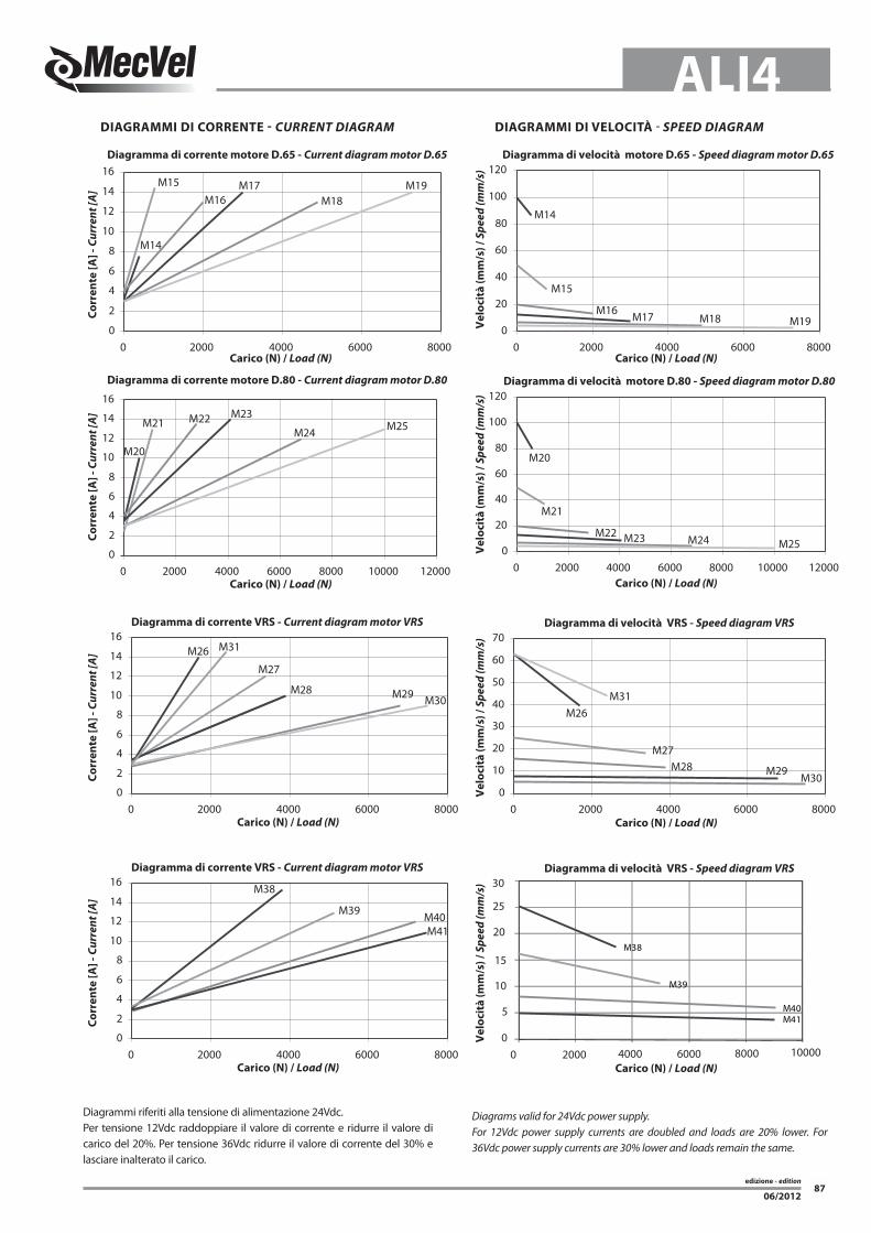
DIAGRAMMI DI CoRReNTe - CuRRENt DIAGRAM DIAGRAMMI DI VeLoCITà - SPEED DIAGRAM
Diagrammi riferiti alla tensione di alimentazione 24Vdc.Per tensione 12Vdc raddoppiare il valore di corrente e ridurre il valore di carico del 20%. Per tensione 36Vdc ridurre il valore di corrente del 30% e lasciare inalterato il carico.
Diagrams valid for 24Vdc power supply.For 12Vdc power supply currents are doubled and loads are 20% lower. For 36Vdc power supply currents are 30% lower and loads remain the same.
M16M18 M19
0
20
40
60
80
100
120
0 2000 4000 6000 8000
M14
M15
M16M17
M18M19
0
2
4
6
8
10
12
14
16
0 2000 4000 6000 8000
M22M24
M21
M20
M250
20
40
60
80
100
120
0 2000 4000 6000 8000 10000 120000
2
4
6
8
10
12
14
16
0 2000 4000 6000 8000 10000 12000
M29
0
10
20
30
40
50
60
70
0 2000 4000 6000 80000
2
4
6
8
10
12
14
16
0 2000 4000 6000 8000
Carico (N) / Load (N) Carico (N) / Load (N)
Carico (N) / Load (N)
Carico (N) / Load (N)
Carico (N) / Load (N)
Carico (N) / Load (N)
Vel
ocit
à (m
m/s
) / S
peed
(mm
/s)
Vel
ocit
à (m
m/s
) / S
peed
(mm
/s)
Vel
ocit
à (m
m/s
) / S
peed
(mm
/s)
M14
M15
Diagramma di velocità motore D.65 - Speed diagram motor D.65 Diagramma di corrente motore D.65 - Current diagram motor D.65
Diagramma di corrente motore D.80 - Current diagram motor D.80
Diagramma di corrente VRS - Current diagram motor VRS
Diagramma di velocità motore D.80 - Speed diagram motor D.80
Diagramma di velocità VRS - Speed diagram VRS
Corr
ente
[A] -
Cur
rent
[A]
Corr
ente
[A] -
Cur
rent
[A]
Corr
ente
[A] -
Cur
rent
[A]
M17
M20
M21 M22 M23
M24 M25
M26
M27
M31
M28 M29 M30
M23
M26
M27
M30
M31
M28
0
5
10
15
20
25
30
0 2000 4000 6000 80000
2
4
6
8
10
12
14
16
0 2000 4000 6000 8000Carico (N) / Load (N) Carico (N) / Load (N)
Vel
ocit
à (m
m/s
) / S
peed
(mm
/s)
Diagramma di corrente VRS - Current diagram motor VRS Diagramma di velocità VRS - Speed diagram VRS
Corr
ente
[A] -
Cur
rent
[A]
M38
M39 M40M41
M38
M39
M40M41
10000

edizione - edition88
ALI4
06/2012
14
Ø30
53 107 + corsa/stroke12160 + corsa/stroke
Ø12
853218
103
26.7
30
55.5
52
75.2
25
Ø50
P
Ø12
Ø
Ø30
39.5
91.5
H
K
+0.1 0
+0.1
0
ALI4 - versione C.C. / D.C. Version
ALI4 - versione C.A. / A.C. Version
ATTuAToRe SeNzA FINe CoRSA / ACtuAtoR wIthout LIMIt SwItChES
DIMENSIONI MOTORI C.A. / A.C. MOTORS DIMENSIONS
GR. / SIZE VERSIONE / TYPE H K Ø P
56Standard 168 116 108
Autofrenante / Brake motors 200
63Standard 190 129 110
Autofrenante / Brake motors 235
71Standard 220 146 121
Autofrenante / Brake motors 267
160 + corsa/stroke107 + corsa/stroke
1453
88
12 55.575
25
Ø50
Ø30
10385
1832
91.5
52
155
Ø12+0.1 0
Ø12+0.1 0
Ø50
Ø85
39.5

edizione - edition89
ALI4
06/2012
Ø50
12
107 + corsa/stroke 83
Ø30
P
14 190 + corsa/stroke
133115
18
32
2690
1243
Ø30
8426
Ø12
52
7655
25
44
Ø
39.5
91.5
H
K
+0.1
0
+0.1 0
ALI4-F - versione C.C. / D.C. Version
ALI4-F - versione C.A. / A.C. Version
ATTuAToRe CoN FINe CoRSA INTeGRATo / ACtuAtoR wIth INtEGRAtED LIMIt SwItChES
DIMENSIONI MOTORI C.A. / A.C. MOTORS DIMENSIONS
GR. / SIZE VERSIONE / TYPE H K Ø P
56Standard 168 116 108
Autofrenante / Brake motors 200
63Standard 190 129 110
Autofrenante / Brake motors 235
71Standard 220 146 121
Autofrenante / Brake motors 267
Ø30
43
5239
.5
91.5
25
47
90
120.5
Ø85
155
12
Ø50
88
190 + corsa
107+ corsa83
14
18
32 133115
Ø12+0.1 0 83.9
Ø30
Ø12+0.1 0
edizione - edition90
ALI4
06/2012
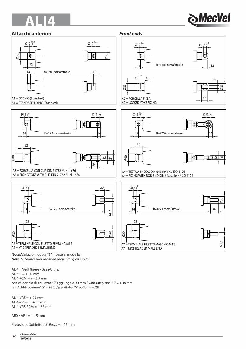
Attacchi anteriori Front ends
Nota: Variazioni quota “B”in base al modelloNote: “B” dimension variations depending on model
ALI4 = Vedi figure / See picturesALI4-F = + 30 mmALI4-FCM = + 42,5 mmcon chiocciola di sicurezza “G” aggiungere 30 mm / with safety nut “G” = + 30 mm(Es. ALI4-F opzione “G” = +30) / (i.e. ALI4-F “G” option = +30)
ALI4-VRS = + 25 mmALI4-VRS-F = + 55 mmALI4-VRS-FCM = + 53 mm
AR0 / AR1 = + 15 mm
Protezione Soffietto / Bellows = + 15 mm
Ø12+0.1 0
A3 = FORCELLA CON CLIP DIN 71752 / UNI 1676A3 = FIXING YOKE WITH CLIP DIN 71752 / UNI 1676
A6 = TERMINALE CON FILETTO FEMMINA M12A6 = M12 TREADED FEMALE END
B=172+corsa/stroke
32
Ø30
14
Ø30
20
M12
B=223+corsa/stroke
B=160+corsa/stroke
Ø12+0.1 0
Ø12+0.1 0
A1 = OCCHIO (Standard)A1 = STANDARD FIXING (Standard)
14
32
Ø30
32
Ø30
Ø12 H8
24
14
12 24
Ø12+0.1 0
Ø30
B=162+corsa/stroke
A4 = TESTA A SNODO DIN 648 serie K / ISO 6126A4 = FIXING WITH ROD END DIN 648 serie K / ISO 6126
Ø12+0.1 0
A7 = TERMINALE FILETTO MASCHIO M12A7 = M12 TREADED MALE END
Ø30
32
14 34
Ø30
B=225+corsa/stroke
B=168+corsa/stroke
27
Ø12+0.1 0
Ø12 H7
Ø30
Ø12+0.1 0
A2 = FORCELLA FISSAA2 = LOCKED YOKE FIXING
Ø30
32
Ø12+0.1 0
32
14
Ø30
12
17
1612
12
14
1214
M12

edizione - edition91
ALI4
06/2012
1 (Standard)
3
24
3
2 (Standard)
4
Attacco posterioreALI4 - ALI4-F
ALI4
Rear end
P1 P2Ruotato di 90°Rotated through 90°
(Standard)
oRIeNTAMeNTo MoRSeTTIeRA E-box PoSItIoN
Dispositivo antirotazioneNella famiglia ALI4 è possibile installare un dispositivo antiro-tazione che vincola le rotazioni dell’asta traslante attorno al pro-prio asse. Con l’attacco anteriore A1 ed A2 sono disponibili due versioni: AR0 con attacco anteriore e posteriore standard (P1) , AR1 con attacco anteriore e posteriore ruotato di 90° (P2). Nei casi di attacco A3, A4, A6, ed A7 è obbligatorio avere il dispositivo antirotazione. Perde di significato la distinzione tra AR0 e AR1: in questo caso si riporta sempre AR0.
Antirotation deviceModel ALI4 can host an antirotation device, allowing push rod not to spin when travelling. Front ends A1 and A2 allow for two anti-rotation settings: AR0 with standard front end and back end (P1), AR1 with front end and back end turned through 90° (P2) . When using A3, A4, A6 and A7 front ends antirotation facility must always be mounted. The distinction between AR0 and AR1 does not make sense: in this case AR0 is than selected
ALI4ALI4-F
AR0 (STANDARD) AR1
M0 M1
1
2
3
4
3
4 2
1StANDARD StANDARD
edizione - edition92
ALI4
06/2012
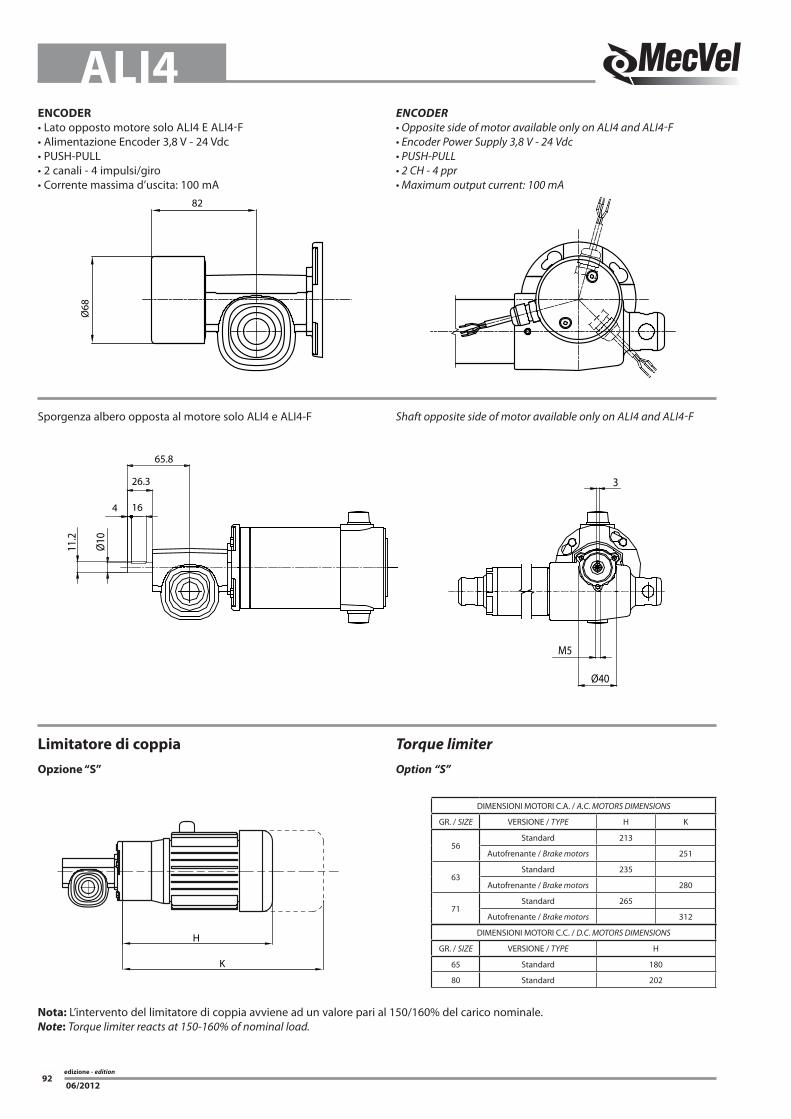
eNCoDeR• Lato opposto motore solo ALI4 E ALI4-F• Alimentazione Encoder 3,8 V - 24 Vdc• PUSH-PULL• 2 canali - 4 impulsi/giro• Corrente massima d’uscita: 100 mA
ENCoDER• Opposite side of motor available only on ALI4 and ALI4-F• Encoder Power Supply 3,8 V - 24 Vdc• PUSH-PULL• 2 CH - 4 ppr• Maximum output current: 100 mA
Ø68
82
Limitatore di coppiaopzione “S”
torque limiteroption “S”
K
H
DIMENSIONI MOTORI C.A. / A.C. MOTORS DIMENSIONS
GR. / SIZE VERSIONE / TYPE H K
56Standard 213
Autofrenante / Brake motors 251
63Standard 235
Autofrenante / Brake motors 280
71Standard 265
Autofrenante / Brake motors 312
DIMENSIONI MOTORI C.C. / D.C. MOTORS DIMENSIONS
GR. / SIZE VERSIONE / TYPE H
65 Standard 180
80 Standard 202
Sporgenza albero opposta al motore solo ALI4 e ALI4-F Shaft opposite side of motor available only on ALI4 and ALI4-F
65.8
26.3
164
Ø10
11.2
Ø40
M5
3
Nota: L’intervento del limitatore di coppia avviene ad un valore pari al 150/160% del carico nominale.Note: Torque limiter reacts at 150-160% of nominal load.
edizione - edition93
ALI4
06/2012
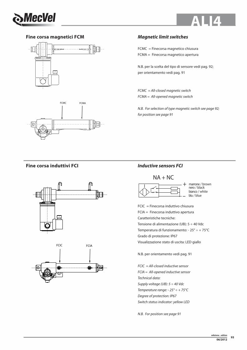
Fine corsa magnetici FCM
Fine corsa induttivi FCI
Magnetic limit switches
Inductive sensors FCI
FCMC = Finecorsa magnetico chiusura
FCMA = Finecorsa magnetico apertura
N.B. per la scelta del tipo di sensore vedi pag. 92;
per orientamento vedi pag. 91
FCMC = All-closed magnetic switch
FCMA = All-opened magnetic switch
N.B. For selection of type magnetic switch see page 92;
for position see page 91
FCIC = Finecorsa induttivo chiusura
FCIA = Finecorsa induttivo apertura
Caratteristiche tecniche:
Tensione di alimentazione (UB): 5 ÷ 40 Vdc
Temperatura di funzionamento: - 25° ÷ + 75°C
Grado di protezione: IP67
Visualizzazione stato di uscita: LED giallo
N.B. per orientamento vedi pag. 91
FCIC = All-closed inductive sensor
FCIA = All-opened inductive sensor
Technical data:
Supply voltage (UB): 5 ÷ 40 Vdc
Temperature range: - 25° ÷ + 75°C
Degree of protection: IP67
Switch status indicator: yellow LED
N.B. For position see page 91
NA + NCnero / blackmarrone / brown
bianco / whiteblu / blue
+
–
I
FCMC FCMA
FCIC FCIA
edizione - edition94
ALI4
06/2012
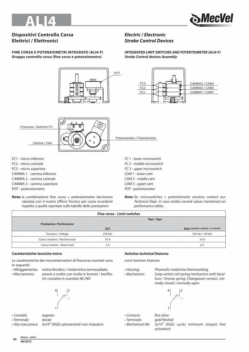
Dispositivi Controllo Corsaelettrici / elettronici
Electric / ElectronicStroke Control Devices
Caratteristiche tecniche micro
Le caratteristiche dei microinterruttori di finecorsa montati sono le seguenti:• Alloggiamento: resina fenolica / melaminica termosaldata• Meccanismo: azione a scatto con molla in bronzo / berillio.
Un contatto in scambio NC/NO
Switches technical features
Limit Switches Features
• Housing: Phoenolic-melamine thermosetting• Mechanism: Snap-action coil spring mechanism with beryl-
lium / bronze spring. Changeover contact, nor-mally-closed / normally-open.
4
1
2 4
1
2
• Contatti: argento• Terminali: dorati• Vita meccanica: 3x10⁵ (XGG) azionamenti non impulsivi.
• Contacts: fine silver• Terminals: gold flashed• Mechanical life: 3x10⁵ (XGG) cycles minimum (impact free
actuation).
CAMMA3 / CAM3
Camma / Cam
Finecorsa / Switches FC
Potenziometro / Potentiometer
CAMMA2 / CAM2CAMMA1 / CAM1
POT
FC3FC2FC1
FC1 - micro inferioreFC2 - micro centraleFC3 - micro superioreCAMMA 1 - camma inferioreCAMMA 2 - camma centraleCAMMA 3 - camma superiorePOT - potenziometro
Nota: la combinazione fine corsa + potenziometro dev’essere valutata con il nostro Ufficio Tecnico per corse eccedenti rispetto a quelle riportate sulle tabelle delle prestazioni
FC 1 - lower microswitchFC 2 - middle microswitchFC 3 - upper microswitchCAM 1 - lower camCAM 2 - middle camCAM 3 - upper camPOT - potentiometer
Note: for microswitches + potentiometer versions contact our Technical Dept. in case strokes exceed values mentioned on performance tables.
FINe CoRSA e PoTeNzIoMeTRI INTeGRATo (ALI4-F)Gruppo controllo corsa (fine corsa e potenziometro)
INtEGRAtED LIMIt SwItChES AND PotENtIoMEtER (ALI4-F)Stroke Control devices Assembly
Fine corsa - Limit switchesTipo / type
Prestazioni / Performance
XCF XGG (speciale a richiesta - on request)
Tensione / Voltage 250 Vac 230 Vac / 30 Vdc
Carico resistivo / Resistive load 10 A 16 A
Carico motore / Motor load 2 A 6 A

edizione - edition95
ALI4
06/2012
1 2 3
90.0°
R4.5
3.29.3
1
2
3 Ø22
.2
SIMBOLO / SYMBOL
A Versione / Version60°
CW
Ø 0.500(12.70)
BC
1
2
3
1
2
3
SIMBOLO / SYMBOL
±0.015
1.31
2(3
3.32
)
0.015(4.75)
0.625(15.88)
±0.0
15
±0.015 ±0.015B Versione / Version
oRIeNTAMeNTo GRuPPo FINe CoRSALIMIt SwItChES box PoSItIoN
oRIeNTAMeNTo FCMFCM PoSItIoN
oRIeNTAMeNTo MoToReMotoR PoSItIoN
oRIeNTAMeNTo FCIFCI PoSItIoN
Potenziometro rotativo - Spinning potentiometerPrestazioni / Performances Tipo / type (A) Tipo / type (B)
Angolo max. di lavoro / Max. angle 340° ± 3° 352° ± 2°Resistenza Ohm / Resistance 1K / 5K / 10K (standard) 1K / 5K / 10K (standard)
Alimentazione consigliata / Voltage MAX 10 V MAX 50 VLinearità indipendente / Indipendent linearity ± 2% ± 1%
Tolleranza / Tolerance ± 20% ± 3%Coefficente deriva termica / Temperature coefficient of resistance 600 ppm / °C 20 ppm / °C
FC1(Standard)
(solo M0/only M0)
FC2(solo M1/only M1)
M1 M0(Standard)
ALI4-F
ALI4-FCIALI4-FCM
1 (Standard)
2
3
4
1 (Standard)
3
2 4

edizione - edition96
ALI4
06/2012
Circuito Reed NCCircuito con ampolla Reed normalmente chiusa protetta da vari-store contro le sovratensioni generate all’apertura del circuito, e sistema di visualizzazione a LED.
Circuito PNPCircuito con effetto di Hall con uscita PNP. Protetto contro l’inversione di polarità e contro picchi di sovra-tensione.Sistema di visualizzazione a LED.
Circuito Reed NoCircuito con ampolla Reed normalmente aperta, protetta da vari-store contro le sovratensioni generate all’apertura del circuito, e sistema di visualizzazione a LED.
Circuit Redd NCCircuit with normally closed Reed switch protected by a varistor against overvoltages caused when switching off, with LED indicator.
Circuit PNP Circuit with Hall-effect switch and PNP outlet.
Protected against overvoltage spikes and reverse of polarity.With LED indicator.
Circuit Redd NoCircuit with normally open Reed switch protected by a varistor against overvoltages caused when switching off, with LED indicator.
+ Vdc
0 Vdc
LINE DRIVER
OutOut
+ Vdc
0 Vdc
PUSH-PULL
Out
Rosso / Red ÷VdcNero / Black 0 VdcVer de / Green AGiallo / Yellow BBlu / Blue ZMarrone / Brown -AArancione / Orange -BBianco / White -Z
eNCoDeR
encoder su motori CA
encoder incrementale bidirezionale con (standard) e senza impulso di zero IP54.
Impulsi giro disponibili: 50 / 100 / 200 / 400 / 500 / 512 /1000 / 1024 (standard)
Circuiti d’uscita disponibili: Line Drive 5 Vdc (standard) Push Pull 24 Vdc / Open Collector NPN 10 -30 Vdc / Open Collector PNP 10 - 30 Vdc.
ENCoDER
Encoder mounted on AC motors
bidirectional incremental encoder, with (standard) or without zero-pulse, protection IP54.
Available ppr: 50 / 100 / 200 / 400 / 500 / 512 / 1000 / 1024 (stan-dard)
Available output circuits: Line Drive 5 Vdc (standard) Push Pull 24 Vdc / Open Collector NPN 10 -30 Vdc / OpenCollector PNP 10 -30 Vdc.
Fine corsa magnetici FCM - FCM magnetic Limit switches
Prestazioni / PerformanceTipo / type
Reed NC Reed No PNPTensione in DC / DC voltage 3 / 110 V 3 / 30 V 6 / 30 VTensione in AC / AC voltage 3 / 110 V 3 / 30 V /
Corrente a 25°C / 25°C Current 0,5 A 0,1 A 0,20 APotenza / Power 20 VA 6 VA 4 W
Cavo alimentazione / Supply cable PVC 2 x 0,14 mm PVC 2 x 0,14 mm PVC 3 x 0,14 mmLunghezza cavo / Cablelenght 2500 mm
Protezione / Protection IP67
Circuito Redd NC / NC Reed Circuit Circuito PNP / PNP Circuit
CaricoLoad
Bl / Bl Bl / Bl Ma / Br
Circuito Reed NO / NO Reed Circuit
Bl / Bl Ma / Br
Ma / Br
Ne / Bk
+
-
Encoder lato opposto motore solo ALI4 E ALI4-F
• Alimentazione Encoder 3,8 V - 24 Vdc• PUSH-PULL• 2 canali - 4 impulsi/giro• Corrente massima d’uscita: 100 mA
Encoder opposite side of motor available only on ALI4 and ALI4-F
• Encoder Power Supply 3,8 V - 24 Vdc• PUSH-PULL• 2 CH - 4 ppr• Maximum output current: 100 mA
MARRONEBIANCOVERDEGIALLO
BROWNWHITEGREENYELLOW
OUT 1OUT 2

edizione - edition97
ALI4
06/2012
RIFeRIMeNTo SIGLA D’oRDINAzIoNe
Fine Corsa Meccanici:2FC2 = 2 Micro XGG3FC2 = 3 Micro XGG
2FCD2 = 2 Micro cablati con diodi XGG3FCD2 = 3 Micro di cui 2 cablati con diodi XGG(solo per motori DC e per carichi fino a 6A di assorbimento)
Fine Corsa Magnetici:2FCM0 = 2 Sensori circuito Reed NC(versione standard in assenza di indicazioni)
2FCM1 = 2 Sensori circuito Reed NO2FCM2 = 2 Sensori PNP
3FCM0= 3 Sensori circuito Reed NC(versione standard in assenza di indicazioni)
3FCM1 = 3 Sensori circuito Reed NO3FCM2= 3 Sensori PNP
Potenziometri:POT01A = 1 k OhmPOT05A = 5 k OhmPOT10A = 10 k Ohm(versioni standard)
POT01B = 1 k OhmPOT05B = 5 k OhmPOT10B = 10 k Ohm(versioni speciali)
encoder:
E01 = Push Pull 2 canali 4 pprE05 = Push Pull 1024 pprE06 = Line Drive 1024 ppr (versione standard)E07 = Open Collector NPNE08 = Open Collector PNP(solo su motore CA)
E09 = Push Pull 1024 pprE10 = Line Drive 1024 pprE11 = Open Collector NPNE12 = Open Collector PNP(solo su cassa attuatore)
E13 = Encoder non contemplato (indicare le caratteristiche nel disegno d’assieme)
oRDERING KEy REFERENCES
Mechanical limit switches:2FC2 = 2 Micro XGG3FC2 = 3 Micro XGG
2FCD2 = 2 XGG Microswitches diode-wired3FCD2 = 3 XGG Microswitches, 2 of them diode-wired(for DC motor only and for loads up to 6A)
Magnetic limit switches:2FCM0 = 2 Sensors circuit Reed NC(standard version without prior information)
2FCM1 = 2 Sensors circuit Reed NO2FCM2 = 2 Sensors PNP
3FCM0 = 3 Sensors circuit Reed NC(standard version without prior information)
3FCM1 = 3 Sensors circuit Reed NO3FCM2 = 3 Sensors PNP
Potentiometers:POT01A = 1 k OhmPOT05A = 5 k OhmPOT10A = 10 k Ohm(standard version)
POT01B = 1 k OhmPOT05B = 5 k OhmPOT10B = 10 k Ohm(standard version)
Encoder:
E01 = Push Pull 2 channels 4 ppr E05 = Push Pull 1024 pprE06 = Line Drive 1024 pprE07 = Open Collector NPNE08 = Open Collector PNP(with AC motor only)
E09 = Push Pull 1024 pprE10 = Line Drive 1024 pprE11 = Open Collector NPNE12 = Open Collector PNP(on actuator case only)
E13 = Special encoder (advise features in drawing)
edizione - edition98
ALI4
06/2012
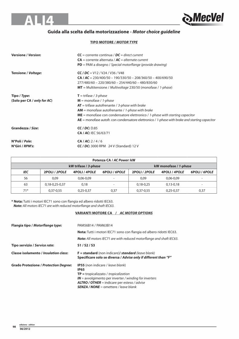
VARIANTI MoToRe CA / AC MotoR oPtIoNS
Flangia tipo / Motorflange type: PAM56B14 / PAM63B14
Nota: Tutti i motori IEC71 sono con flangia ed albero ridotti IEC63.
Note: All motors IEC71 are with reduced motorflange and shaft IEC63.
Tipo servizio / Service rate: S1 / S2 / S3
Classe isolamento / Insulation class: F = standard (non indicare)/ standard (leave blank) Specificare solo se diversa / Advise only if different than “F”
Grado Protezione / Protection Degree: IP55 (non indicare / leave blank) IP65 TP = tropicalizzato / tropicalization IN = avvolgimento per inverter / winding for inverters ALtRo / othER = indicare per esteso / advise SENZA / NoNE = omettere / leave blank
Potenza CA / AC Power: kW
kW trifase / 3-phase kW monofase / 1-phase
IEC 2PoLI / 2PoLE 4PoLI / 4PoLE 6PoLI / 6PoLE 2PoLI / 2PoLE 4PoLI / 4PoLE 6PoLI / 6PoLE
56 0,09 0,06-0,09 - 0,09 0,06-0,09 -
63 0,18-0,25-0,37 0,18 - 0,18-0,25 0,13-0,18 -
71* 0,37-0,55 0,25-0,37 0,37 0,37-0,55 0,25-0,37 0,37
Guida alla scelta della motorizzazione - Motor choice guideline
TIPo MoToRe / MotoR tyPE
Versione / Version: CC = corrente continua / DC = direct current CA = corrente alternata / AC = alternate current PD = PAM a disegno / Special motorflange (provide drawing)
Tensione / Voltage: CC / DC = V12 / V24 / V36 / V48 CA / AC = 230/400/50 – 190/330/50 – 208/360/50 – 400/690/50 277/480/60 – 220/380/60 – 254/440/60 – 480/830/60 MT = Multitensione / Multivoltage 230/50 (monofase / 1-phase)
Tipo / type: T = trifase / 3-phase(Solo per CA / only for AC) M = monofase / 1-phase AT = trifase autofrenante / 3-phase with brake AM = monofase autofrenante / 1-phase with brake Me = monofase con condensatore elettronico / 1-phase with starting capacitor Ae = monofase autofr. con condensatore elettronico / 1-phase with brake and starting capacitor
Grandezza / Size: CC / DC: D.85 CA / AC: IEC 56/63/71
N°Poli / Pole: CA / AC: 2 / 4 / 6N°Giri / RPM’s: CC / DC: 3000 RPM 24 V (Standard) 12 V
* Nota: Tutti i motori IEC71 sono con flangia ed albero ridotti IEC63. Note: All motors IEC71 are with reduced motorflange and shaft IEC63.

edizione - edition99
ALI4
06/2012
Freno / brake: FeCC = freno elettromagnetico negativo in CC / DC brake negative action (standard)
Tensione di alimentazione 230V± 10% 50/60Hz dal lato A.C. dell’alimentatore freno. Il freno viene alimentato direttamente dall’alimentazione del motore. (standard) Sono disponibili a richiesta motori con freni con alimentazione separata e con tensioni nel range (24-205 Vdc) In questo caso il freno necessita di una alimentazione separata da quella del motore. In questo caso la sigla diventa FeCC-AS-24Vdc
Power Supply 230V±10% 50/60Hz AC side inside the brake. The brake is powered directly from the power supply of the motor (standard) Motors with separated brake power supply and tensions in the range (24-205 Vdc) can be available on request. In this case the brake needs a separated power supply from the motor and its code becomes FeCC-AS-24 Vdc FeCA= freno elettromagnetico in CA / AC brake Tensione di alimentazione 230/400V± 10% 50/60Hz. Il freno viene alimentato direttamente dall’alimentazione del motore. Sono disponibili a richiesta motori con freni con alimentazione separata e con tensioni nel range (24-690 Vac) 50/60 HZ In questo caso il freno necessita di una alimentazione separata da quella del motore. In questo caso la sigla diventa FeCA-AS-230 Vac 50 Hz
Power Supply 230/400V±10% 50/60Hz. The brake is powered directly from the power supply of the motor. Motors with separated brake power supply and tensions in the range (24-690 Vac - 50/60 Hz) can be available on request. In this case the brake needs a separated power supply from the motor and its code becomes FeCA-AS-230 Vac 50 Hz
Alimentazione separata del freno / Separate brake power supply: si ottiene tramite una morsettiera ausiliaria, con fissati i morsetti delle bobine freno, posizionata all’interno del coprimorsettiera motore. achieved by means of an auxiliary terminal board, with fixed brake coil terminals, located inside the motor terminal box.
Nb. Per tutti i motori predisposti inverter il freno deve avere senpre l’alimentazione separata Nb. On all motors prepared for frequency converter the brake must always have a separate power supply
SeNzA = omettere / No bRAKE = leave blank
opzioni / options: LS = leva sblocco / hand release lever (non indicare / leave blank) Nota: = non disponibile per motori IEC 50 IEC 56 / NotE: not available for motor IEC 50 IEC 56
Ab = albero bisporgente / 2’shaft IN = avvolgimento per inverter / winding for inverters ALtRo / othER = indicare per esteso / advise SENZA / NoNE = omettere / leave blank

edizione - edition
06/2012100
NoTe NotES
edizione - edition101
ALI4
06/2012
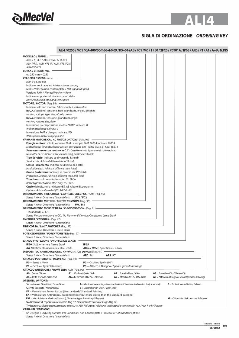
SIGLA DI oRDINAzIoNe - oRDERING KEy
ALI4 / 0250 / M01 / CA-400/50-T-56-4-0,09 / B5+S1+AB / FC1 /M0 / 1 / e0 / 2FC0 / P0T01A / IP65 / AR0 / P1 / A1 / A+B / N.DIS
MoDeLLo / MoDEL: ALI4 / ALI4-F / ALI4-FCM / ALI4-FCI ALI4-VRS / ALI4-VRS-F / ALI4-VRS-FCM ALI4-VRS-FCI CoRSA / StRoKE: mm es. 250 mm = 0250VeLoCITà / SPEED: mm/s ALI4 (Pag. 85-86) Indicare: vedi tabelle / Advise: choose among M00 = Velocità non contemplate / Not standard speed Versione PAM / Flanged Version = Rpm Indicare rapporto riduzione + passo stelo Advise reduction ratio and screw pitchMoToRe / MotoR: (Pag. 98) Indicare solo con motore: / Advise only if with motor: In C.A.: versione, tensione, tipo, grandezza, n°poli, potenza version, voltage, type, size, n°pole, power In C.C.: versione, tensione, grandezza, n°giri version, voltage, size, Rpm In versione predisposizione motore “PAM” indicare: 0 With motorflange only put 0 In versione PAM a disegno indicare: PD With special motorflange put: PDVARIANTI MoToRe CA / AC MotoR oPtIoNS: (Pag. 98) Flangia motore: solo in versione PAM - esempio PAM 56B14 indicare 56B14 Motorflange: for motorflange version only advise size - i.e.for IEC56 B14 put 56B14 Senza motore o con motore in C.C.: Omettere tutti i parametri sottoindicati No motor or DC motor: leave all following parameters blank Tipo Servizio: Indicare se diverso da S3 (std) Service rate: Advise if different than S3 (std) Classe isolamento: Indicare se diverso da F (std) Insulation class: Advise if different than F (std) Grado Protezione: Indicare se diverso da IP55 (std) Protection Degree: Advise if different than IP55 (std) Tipo freno: solo se autofrenante: ES. FECA Brake type: for brakemotors only: ES. FECA opzioni: Indicare se richiesto (ES. AB Albero Bisporgente) Options: Advise if needed (ES. AB 2’shaft)oRIeNTAMeNTo FINe CoRSA / LIMIt SwItChES PoSItIoN: (Pag. 95) Senza / None: Omettere / Leave blank FC1 / FC2oRIeNTAMeNTo MoToRe / MotoR PoSItIoN: (Pag. 95) Senza / None: Omettere / Leave blank M0 / M1oRIeNTAMeNTo MoRSeTTIeRA / E-box PoSItIoN: (Pag. 91) 1 (Standard), 2, 3, 4 Senza Motore o motore in CC / No Motor or DC motor: Omettere / Leave blankeNCoDeR / ENCoDER: (Pag. 97) Senza / None: Omettere / Leave blankFINe CoRSA / LIMIt SwItChES: (Pag. 97) Senza / None: Omettere / Leave blankPoTeNzIoMeTRo / PotENtIoMEtER: (Pag. 97) Senza / None: Omettere / Leave blankGRADo PRoTezIoNe / PRotECtIoN CLASS: IP50 (Std): omettere / leave blank IP65 AA Allestimento Acciaierie / Steel works Altro / other: Specificare / AdviseDISPoSITIVo ANTIRoTAzIoNe / ANtIRotAtIoN DEVICE: (Pag. 91) Senza / None: Omettere / Leave blank AR0: Std AR1: 90°ATTACCo PoSTeRIoRe / REAR END: (Pag. 91) P0 = Senza / None P2 = Occhio / Eyelet (90°) P1 = Occhio / Eyelet (standard) P3 = Attacco a Disegno / Special (provide drawing)ATTACCo ANTeRIoRe / FRoNt END: ALI4 (Pag. 90) A0 = Senza / None A1 = Occhio / Eyelet (Std) A2 = Forcella Fissa / Yoke A3 = Forcella + Clip / Yoke + Clip A4 = Testa a Snodo / Rod end A6 = Femmina M12 / M12 female A7 = Maschio M12 / M12 male A9 = Attacco a Disegno / Special (provide drawing)oPzIoNI / oPtIoNS: Senza / None: Omettere / Leave blank A = Versione Inox (asta, attacco anteriore) / Stainless steel version (rod, front end) B = Protezione soffietto / Bellows C = Vite Scoperta / Naked Screw e = Guarnizioni in viton / Viton seals FF = Verniciatura Ferromicacea (blu standard)/ Standard Painting FA = Verniciatura Antirombo / Painting (milder but more elestic than the standard painting) FM = Verniciatura Marina (5 strati) / Marine type Painting (5 layers) G = Chiocciola di sicurezza / Safety nut S = Limitatore di coppia su asse motore (Pag. 92) / Torque limiter on motor flange (Pag. 92) T = Sporgenza albero opposta motore (solo ALI4 / ALI4-F) (Pag.92)/ Additional shaft (opposite to motorside - ALI4 / ALI4-F only) (Pag. 92)VARIANTI / VERSIoNS: N° Disegno / Drawing number: Per Condizioni non Contemplate / Presence of not standard options Senza / None: Omettere / Leave blank

edizione - edition
06/2012102
NoTe NotES


![Ballscrew 3020-3040 Cnc Router GUIDE[1]](https://img.pdfslide.us/doc/110x75/55cf9758550346d033911b17/ballscrew-3020-3040-cnc-router-guide1.jpg)