Embed Size (px)
Citation preview
Bruker BioSpin
GRASI
think forw
Gradient and Shim Interface Unit
User ManualNard
Versio
n 001MR Spectroscopy
The information in this manual may be altered without notice.
BRUKER BIOSPIN accepts no responsibility for actions taken as a result of use of this manual. BRUKER BIOSPIN accepts no liability for any mistakes contained in the manual, leading to coincidental damage, whether during installation or operation of the instrument. Unauthorised reproduction of manual contents, without written permission from the publishers, or translation into an other language, either the entire manual or a part of it, is forbidden.
This manual describes the units as they are at the date of printing. On request, the manufacturer shall supply circuit diagrams, lists of components, descriptions, calibrating instructions and any other information for use by qualified personnel of the user, in charge of repairing the parts of the unit which have been stated by the manufacturer to be "repairable". Such supply shall in no event constitute permission to modify or repair the units or approval of the same.
All rights reserved for the units, circuits, processes and appellations mentioned herein.
This unit is not designed for any type of use which is not specifically described in this manual. Such use may be hazardous.
This manual was written by
Eric Schatz and Vincent Brosseau
This manual was edited and desktop published by
Dominique Wurtz
© September 29, 2009: Bruker BioSpin
Wissembourg, France
P/N: Z31822DWG-Nr: Z4D10372
For further technical assistance on the GRASI unit, please do not hesitate to contact your nearest BRUKER dealer or contact us directly at:
BRUKER BioSpin 34 rue de l’Industrie F-67166 Wissembourg Cedex France Phone: + 33 388 066 000 Fax: + 33 388 736 820 Email: [email protected] Internet: www.bruker.com
Contents
Contents ............................................................................ 3
1 Introduction ........................................................................ 5
2 Safety .................................................................................. 72.1 Instructions ......................................................................................... 72.2 Labels ................................................................................................ 7
Identifying plate ............................................................................. 7Manufacturer’s nameplate .............................................................. 8Warning signs ................................................................................ 9
3 Installation .........................................................................113.1 Initial inspection ............................................................................... 11
Mechanical check ........................................................................ 11Claim for damage ......................................................................... 11Reshipment and repackaging requirements .................................. 11Environment requirements ........................................................... 12
3.2 Installation requirements ................................................................... 12Bench operation ........................................................................... 12
3.3 System check ................................................................................... 123.4 Initial turn on procedure .................................................................... 12
4 Operation .......................................................................... 134.1 General fonctions ............................................................................. 13
Amplifier selection ........................................................................ 14Coil code selection ....................................................................... 14Powering up ................................................................................. 14Initialisation process .................................................................... 14Calibration ................................................................................... 14
4.2 Error messages ................................................................................ 15
5 Technical description ....................................................... 175.1 General description .......................................................................... 175.2 Power requirements .......................................................................... 17
Main characteristics ................................................................ 175.3 Front panel connectors ..................................................................... 185.4 Front panel indicators ....................................................................... 195.5 Front panel buttons ........................................................................... 195.6 Rear panel connectors ...................................................................... 19
Gradient Coil Code connector from Gradient set .......................... 19Status and Command connector from GPSCU .............................. 20Status and Command connector to amplifier ................................. 21
User Manual Version 001 BRUKER BIOSPIN 3 (41)
Interlock Binder connector ........................................................... 22Coil Code Binder connector ......................................................... 22B0 Output Twinaxe connector ...................................................... 23Interface Connector Ethernet 10/100 ........................................... 23
5.7 Rear panel overview ......................................................................... 24
6 Servicing the GRASI .........................................................256.1 Accessing the GRASI unit ................................................................ 256.2 Sub Toolbar Information ................................................................... 26
Device Information ...................................................................... 26Device Status .............................................................................. 27BIS Content ................................................................................. 28
6.3 Sub Toolbar Basic Operations .......................................................... 29Offsets ........................................................................................ 29Reset Error .................................................................................. 30
6.4 Sub Toolbar Maintenance ................................................................. 31Settings Update ........................................................................... 31Firmware Update ......................................................................... 32Device Reset ............................................................................... 33
6.5 Sub Toolbar Diagnostics ................................................................... 34Event Log .................................................................................... 34
7 Specification .....................................................................357.1 General specifications ...................................................................... 35
Figures ............................................................................. 37
Tables ............................................................................... 39
4 (41) BRUKER BIOSPIN User Manual Version 001
1Introduction 1
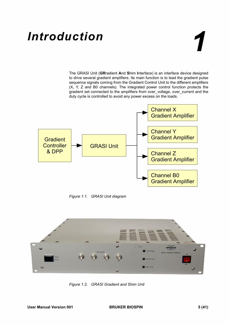
The GRASI Unit (GRradient And Shim Interface) is an interface device designed to drive several gradient amplifiers. Its main function is to lead the gradient pulse sequence signals coming from the Gradient Control Unit to the different amplifiers (X, Y, Z and B0 channels). The integrated power control function protects the gradient set connected to the amplifiers from over_voltage, over_current and the duty cycle is controlled to avoid any power excess on the loads.
Figure 1.1. GRASI Unit diagram
Figure 1.2. GRASI Gradient and Shim Unit
GradientController GRASI Unit
Channel XGradient Amplifier
Channel ZGradient Amplifier
Channel YGradient Amplifier
Channel B0Gradient Amplifier
& DPP
User Manual Version 001 BRUKER BIOSPIN 5 (41)
Introduction
6 (41) BRUKER BIOSPIN User Manual Version 001
2Safety 2
The GRASI is in accordance with the standard IEC/61010-1:2001 safety Requirements for Electrical Equipments.
Instructions 2.1
The GRASI Unit contains live parts. Using the device with cover removed is forbidden.
Risk of electrical shocks! Be sure of voltage absence before every intervention on the device.
The different wirings must be done by an authorized and qualified technician. Use only the provided cables. Never disconnect any cable during the use of the device.
Sprinkling or pouring liquids on the device is forbidden. Use a wet or alcohol soaked rag to clean the EMB.
For corrective actions contact the BRUKER BIOSPIN representative in your coun-try.
Labels 2.2
Labels are provided to alert operating and service personnel to conditions that may cause personal injury or damage to the equipment from misuse or abuse. Please read the labels and understand their meaning.
Identifying plate 2.2.1
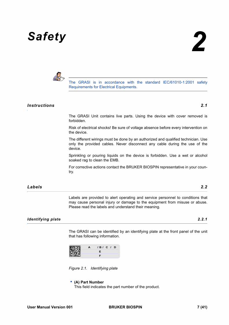
The GRASI can be identified by an identifying plate at the front panel of the unit that has following information.
Figure 2.1. Identifying plate
• (A) Part Number This field indicates the part number of the product.
A / / /B C DEF
User Manual Version 001 BRUKER BIOSPIN 7 (41)
Safety
• (B) Variant This field indicates the variant number that identifies the production category of the product. The default variant is 00.
• (C) ECL This field indicates the revision number that identifies the product configuration. The initial revision is 0.00.
• (D) Serial Number This field indicates the serial number of the product.
• (E) Type This field contains the designation of the product.
• (F) Information This field contains additional information about the product.
Manufacturer’s nameplate 2.2.2
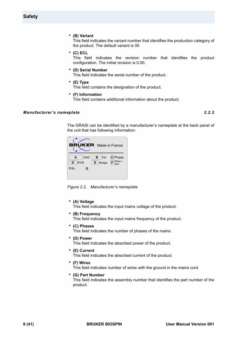
The GRASI can be identified by a manufacturer’s nameplate at the back panel of the unit that has following information:
Figure 2.2. Manufacturer’s nameplate
• (A) Voltage This field indicates the input mains voltage of the product.
• (B) Frequency This field indicates the input mains frequency of the product.
• (C) Phases This field indicates the number of phases of the mains.
• (D) Power This field indicates the absorbed power of the product.
• (E) Current This field indicates the absorbed current of the product.
• (F) Wires This field indicates number of wires with the ground in the mains cord.
• (G) Part Number This field indicates the assembly number that identifies the part number of the product.
Hz
Made in France
VACWires +
A B C PhaseFD KVA GndE Amps
P/N : G
8 (41) BRUKER BIOSPIN User Manual Version 001
Labels
Warning signs 2.2.3
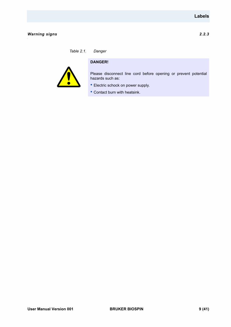
Table 2.1. Danger
DANGER!
Please disconnect line cord before opening or prevent potential hazards such as:
• Electric schock on power supply.
• Contact burn with heatsink.
User Manual Version 001 BRUKER BIOSPIN 9 (41)

Safety
10 (41) BRUKER BIOSPIN User Manual Version 001
3Installation 3
The installation of the device must be done only by an authorized and qualified technician, in total accordance with the running standards. Every breakdown due to a non-respect of the following instructions will not be attributable to Bruker and will not be covered by the guarantee clauses.
Initial inspection 3.1
Mechanical check 3.1.1
If damage of the shipping carton is evident, request the carrier's agent to be present when the instrument is unpacked. Check the equipment for damage and inspect the panel surfaces for dents and scratches.
Claim for damage 3.1.2
If the unit is mechanically damaged or fails to meet specifications upon receipt, notify BRUKER or our representative immediately. Retain the shipping carton and packing material for the carriers inspection as well as for subsequent use in re-turning the unit if necessary.
Reshipment and repackaging requirements 3.1.3
Whenever possible, the original carton and packing material should be used for reshipment. If the original packing material is not available, wrap the instrument in heavy paper or plastic. Use a strong shipping container. If a cardboard is used, it should be at least 200 lbs. test material.
Use shock absorbing material around all sides of the instrument to provide a firm cushion and to prevent from movements inside the container wall on each side. Protect the front panel by means of cardboard spacers inserted between the front panel and the shipping carton. Make sure that the instrument cannot move in the container during shipping. Seal the carton with a good grade of shipping tape and mark the container :
" FRAGILE ELECTRONIC INSTRUMENT. "
User Manual Version 001 BRUKER BIOSPIN 11 (41)
Installation
Environment requirements 3.1.4
This GRASI unit is build for inside use only on a maximum high level of 2000m above sea level (6600 feet). No specific cooling or ventilation is required. Be sure that the GRASI unit has enough area around so that the free air flow into and out of the GRASI unit is not obstructed. It should, however, be in an environment which conforms, the 5°C - 45°C (41°F - 113°F) thermal specifications, a 80% maximum relative humidity of air and a contamination level of 2 (means a normal, only non conductive contamination, temporary conductivity due to condensation is possible).
Installation requirements 3.2
No special precautions are necessary. Mount the equipment in an area which is relatively free of vibration, and has sufficient room for cable connections. The GRASI unit is a class II of installation category.
Bench operation 3.2.1
The unit can be placed onto a secure flat surface.
System check 3.3
Before applying power for the first time the following items should be checked:
• The AC input voltage 220-230 VAC ± 15% range must be compatible with.
• All the necessary cables are connected regarding the labels.
Initial turn on procedure 3.4
The following list describes how to turn on the GRASI unit and what should be seen as this occurs.
Before starting this procedure, make sure that you have properly followed instructions in the section "System check".
1. Connect the amplifier to the AC line and turn the circuit breaker to ON.
2. Observe the indicators on the front panel : - The ON/OFF switch lights red. - After a few seconds, the 3 front panel LEDs light up red and the initialisation process is started.
3. After approximatively one minute, the LEDs turn off. The GRASI unit is ready for use.
4. If the LEDs do not turn off, see the"Troubleshooting" on page 15.
12 (41) BRUKER BIOSPIN User Manual Version 001
4Operation 4
General fonctions 4.1
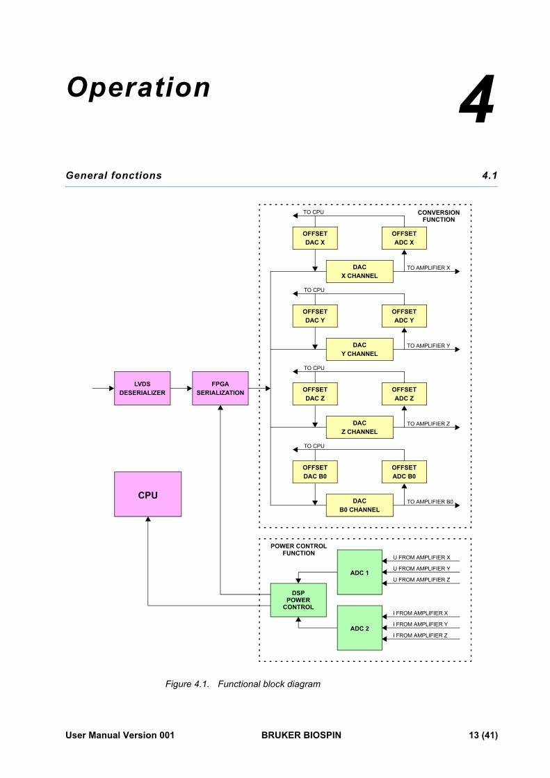
Figure 4.1. Functional block diagram
LVDSDESERIALIZER
FPGASERIALIZATION
OFFSETDAC Y
OFFSETADC Y
DACY CHANNEL
OFFSETDAC B0
OFFSETADC B0
DACB0 CHANNEL
OFFSETDAC X
OFFSETADC X
DACX CHANNEL
OFFSETDAC Z
OFFSETADC Z
DACZ CHANNEL
TO CPU
TO CPU
TO CPU
TO CPU
TO AMPLIFIER B0
TO AMPLIFIER Z
TO AMPLIFIER Y
TO AMPLIFIER X
DSP
U FROM AMPLIFIER X
U FROM AMPLIFIER Y
U FROM AMPLIFIER Z
I FROM AMPLIFIER X
I FROM AMPLIFIER Y
I FROM AMPLIFIER Z
ADC 1
ADC 2
CPU
CONVERSION
POWER CONTROLFUNCTION
FUNCTION
POWERCONTROL
User Manual Version 001 BRUKER BIOSPIN 13 (41)
Operation
Amplifier selection 4.1.1
The first step before starting is to select the type of amplifier used with the GRASI unit. This selection is performed using a dedicated Web page. This action should be done only by Bruker trained personnel. Choosing a wrong amplifier type can lead to irreversible damage of the entire spectrometer. The selection is done once at the first switch on. Once this selection is made, there should be no reason to select another type of amplifier. If for any reason a change of amplifier type is made, the type of the previously selected amplifier will be saved for safety reasons.
Coil code selection 4.1.2
The Coil Code selection occurs automatically when the SUB-D 37 connector is inserted. The code is detected and in accordance with the selected amplifier, the different limit values for the power control are set. The control function supported by the DSP uses these values to check if a limit is overridden.
Powering up 4.1.3
The GRASI Unit is switched on helps the "ON/OFF" button located on the front panel.
Initialisation process 4.1.4
The initialisation process needs about one minute to be completed. During the initialisation process, the output channels are calibrated and the offset corrected.
Important : After switching on the GRASI Unit, the switch light lights red. A few seconds after switching on, the three front panel LEDs light up red and remain lightened for about one minute. This is the external sign for the operator to announce initialisation process. Once the three front panel LEDs switched off, the GRASI Unit is ready for operation. Please note that during initialisation process, no commands should be sent to the GRASI Unit.
Calibration 4.1.5
Before the device can be used for imaging application, all calibration steps must be done according to the ParaVision/TopSpin tune-up procedure.
Warning : Danger harware damage. Missing or wrong calibration settings can lead to destruction of gradient hardware and insufficient image quality.
14 (41) BRUKER BIOSPIN User Manual Version 001
Error messages
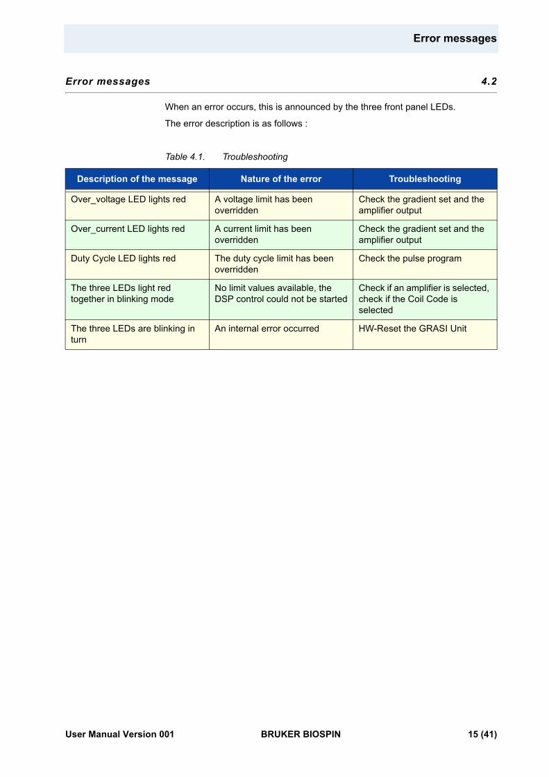
Error messages 4.2
When an error occurs, this is announced by the three front panel LEDs.
The error description is as follows :
Table 4.1. Troubleshooting
Description of the message Nature of the error Troubleshooting
Over_voltage LED lights red A voltage limit has been overridden
Check the gradient set and the amplifier output
Over_current LED lights red A current limit has been overridden
Check the gradient set and the amplifier output
Duty Cycle LED lights red The duty cycle limit has been overridden
Check the pulse program
The three LEDs light red together in blinking mode
No limit values available, the DSP control could not be started
Check if an amplifier is selected, check if the Coil Code is selected
The three LEDs are blinking in turn
An internal error occurred HW-Reset the GRASI Unit
User Manual Version 001 BRUKER BIOSPIN 15 (41)
Operation
16 (41) BRUKER BIOSPIN User Manual Version 001
5Technical description 5
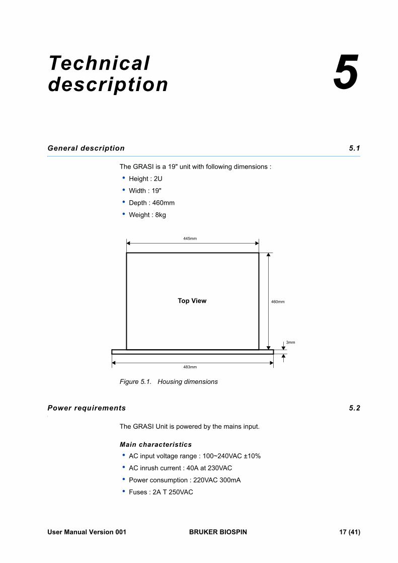
General description 5.1
The GRASI is a 19" unit with following dimensions :
• Height : 2U
• Width : 19"
• Depth : 460mm
• Weight : 8kg
Figure 5.1. Housing dimensions
Power requirements 5.2
The GRASI Unit is powered by the mains input.
Main characteristics• AC input voltage range : 100~240VAC ±10%
• AC inrush current : 40A at 230VAC
• Power consumption : 220VAC 300mA
• Fuses : 2A T 250VAC
483mm
3mm
460mm
445mm
Top View
User Manual Version 001 BRUKER BIOSPIN 17 (41)
Technical description
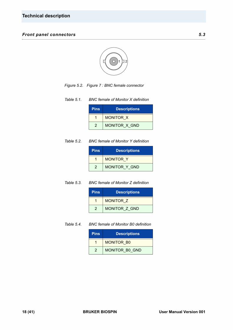
Front panel connectors 5.3
Figure 5.2. Figure 7 : BNC female connector
Table 5.1. BNC female of Monitor X definition
Table 5.2. BNC female of Monitor Y definition
Table 5.3. BNC female of Monitor Z definition
Table 5.4. BNC female of Monitor B0 definition
Pins Descriptions
1 MONITOR_X
2 MONITOR_X_GND
Pins Descriptions
1 MONITOR_Y
2 MONITOR_Y_GND
Pins Descriptions
1 MONITOR_Z
2 MONITOR_Z_GND
Pins Descriptions
1 MONITOR_B0
2 MONITOR_B0_GND
21
18 (41) BRUKER BIOSPIN User Manual Version 001
Front panel indicators
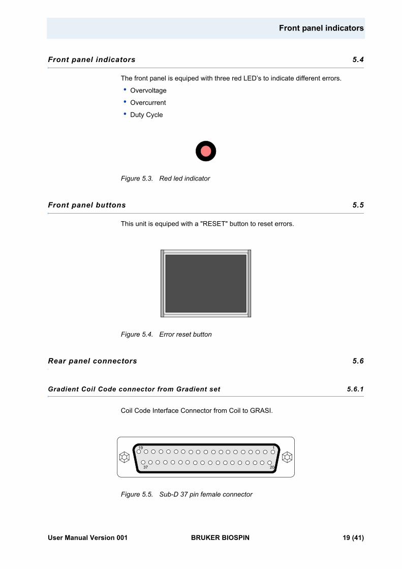
Front panel indicators 5.4
The front panel is equiped with three red LED’s to indicate different errors.
• Overvoltage
• Overcurrent
• Duty Cycle
Figure 5.3. Red led indicator
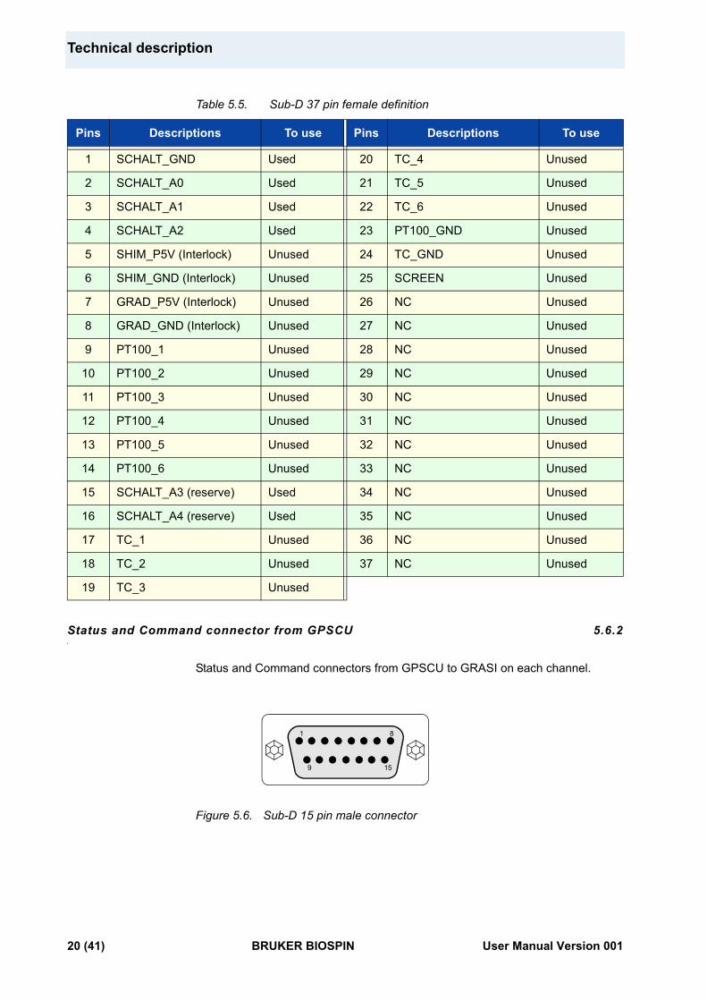
Front panel buttons 5.5
This unit is equiped with a "RESET" button to reset errors.
Figure 5.4. Error reset button
Rear panel connectors 5.6
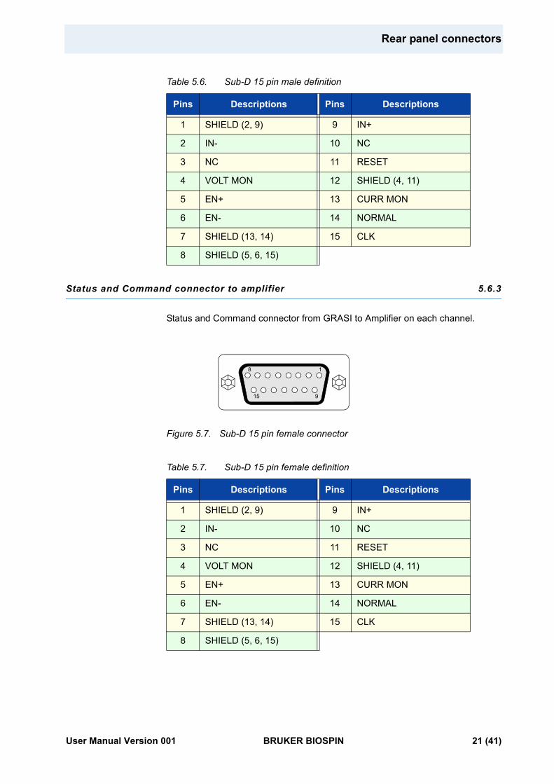
Gradient Coil Code connector from Gradient set 5.6.1
Coil Code Interface Connector from Coil to GRASI.
Figure 5.5. Sub-D 37 pin female connector
37
19
20
1
User Manual Version 001 BRUKER BIOSPIN 19 (41)
Technical description
Table 5.5. Sub-D 37 pin female definition
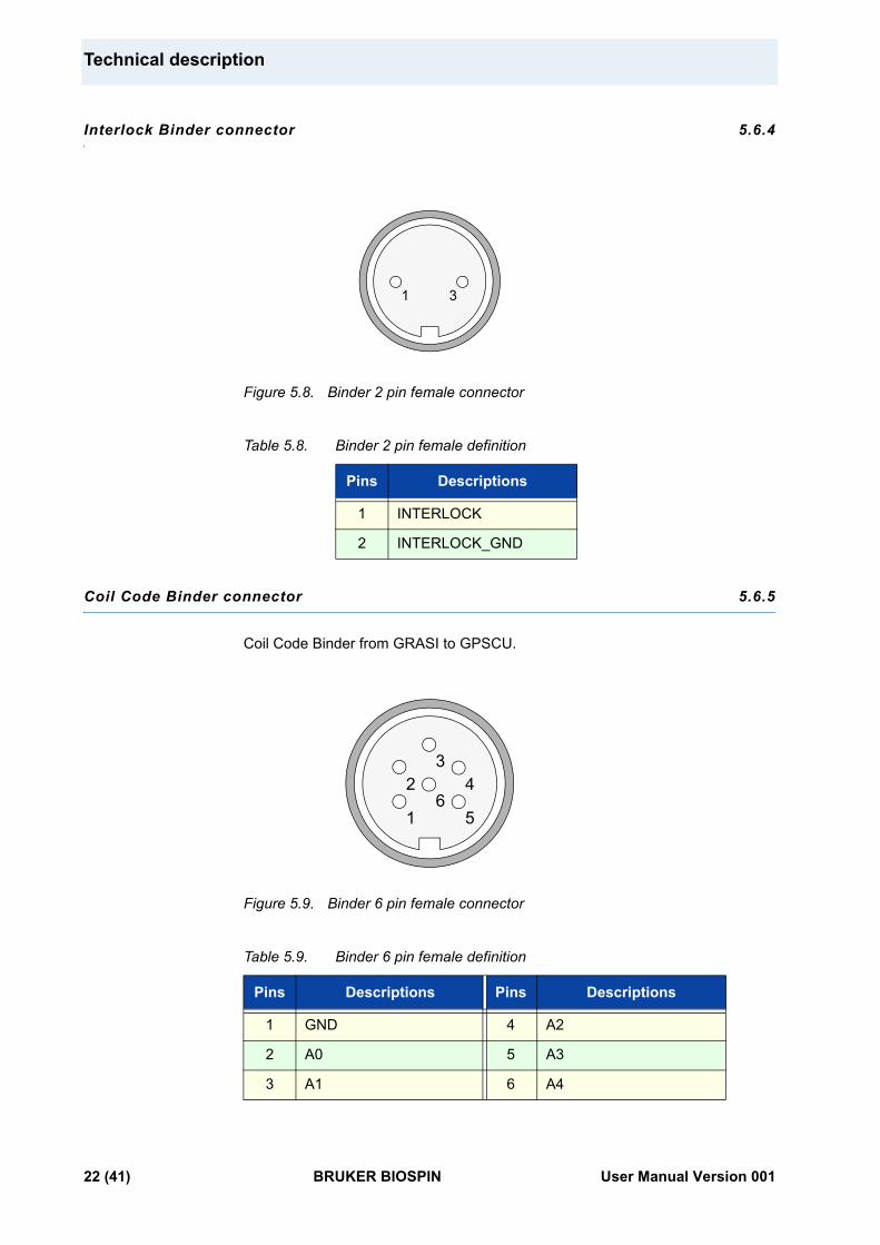
Status and Command connector from GPSCU 5.6.2
Status and Command connectors from GPSCU to GRASI on each channel.
Figure 5.6. Sub-D 15 pin male connector
Pins Descriptions To use Pins Descriptions To use
1 SCHALT_GND Used 20 TC_4 Unused
2 SCHALT_A0 Used 21 TC_5 Unused
3 SCHALT_A1 Used 22 TC_6 Unused
4 SCHALT_A2 Used 23 PT100_GND Unused
5 SHIM_P5V (Interlock) Unused 24 TC_GND Unused
6 SHIM_GND (Interlock) Unused 25 SCREEN Unused
7 GRAD_P5V (Interlock) Unused 26 NC Unused
8 GRAD_GND (Interlock) Unused 27 NC Unused
9 PT100_1 Unused 28 NC Unused
10 PT100_2 Unused 29 NC Unused
11 PT100_3 Unused 30 NC Unused
12 PT100_4 Unused 31 NC Unused
13 PT100_5 Unused 32 NC Unused
14 PT100_6 Unused 33 NC Unused
15 SCHALT_A3 (reserve) Used 34 NC Unused
16 SCHALT_A4 (reserve) Used 35 NC Unused
17 TC_1 Unused 36 NC Unused
18 TC_2 Unused 37 NC Unused
19 TC_3 Unused
9 15
81
20 (41) BRUKER BIOSPIN User Manual Version 001
Rear panel connectors
Table 5.6. Sub-D 15 pin male definition
Status and Command connector to amplifier 5.6.3
Status and Command connector from GRASI to Amplifier on each channel.
Figure 5.7. Sub-D 15 pin female connector
Table 5.7. Sub-D 15 pin female definition
Pins Descriptions Pins Descriptions
1 SHIELD (2, 9) 9 IN+
2 IN- 10 NC
3 NC 11 RESET
4 VOLT MON 12 SHIELD (4, 11)
5 EN+ 13 CURR MON
6 EN- 14 NORMAL
7 SHIELD (13, 14) 15 CLK
8 SHIELD (5, 6, 15)
Pins Descriptions Pins Descriptions
1 SHIELD (2, 9) 9 IN+
2 IN- 10 NC
3 NC 11 RESET
4 VOLT MON 12 SHIELD (4, 11)
5 EN+ 13 CURR MON
6 EN- 14 NORMAL
7 SHIELD (13, 14) 15 CLK
8 SHIELD (5, 6, 15)
15 9
18
User Manual Version 001 BRUKER BIOSPIN 21 (41)
Technical description
Interlock Binder connector 5.6.4
Figure 5.8. Binder 2 pin female connector
Table 5.8. Binder 2 pin female definition
Coil Code Binder connector 5.6.5
Coil Code Binder from GRASI to GPSCU.
Figure 5.9. Binder 6 pin female connector
Table 5.9. Binder 6 pin female definition
Pins Descriptions
1 INTERLOCK
2 INTERLOCK_GND
Pins Descriptions Pins Descriptions
1 GND 4 A2
2 A0 5 A3
3 A1 6 A4
14
3
1
43
5
26
22 (41) BRUKER BIOSPIN User Manual Version 001
Rear panel connectors
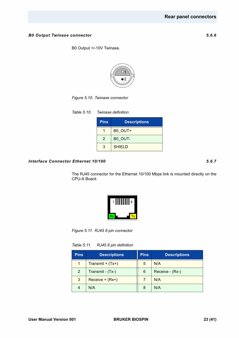
B0 Output Twinaxe connector 5.6.6
B0 Output +/-10V Twinaxe.
Figure 5.10. Twinaxe connector
Table 5.10. Twinaxe definition
Interface Connector Ethernet 10/100 5.6.7
The RJ45 connector for the Ethernet 10/100 Mbps link is mounted directly on the CPU-A Board.
Figure 5.11. RJ45 8 pin connector
Table 5.11. RJ45 8 pin definition
Pins Descriptions
1 B0_OUT+
2 B0_OUT-
3 SHIELD
Pins Descriptions Pins Descriptions
1 Transmit + (Tx+) 5 N/A
2 Transmit - (Tx-) 6 Receive - (Rx-)
3 Receive + (Rx+) 7 N/A
4 N/A 8 N/A
1
2
TxRx
1 8
User Manual Version 001 BRUKER BIOSPIN 23 (41)
Technical description
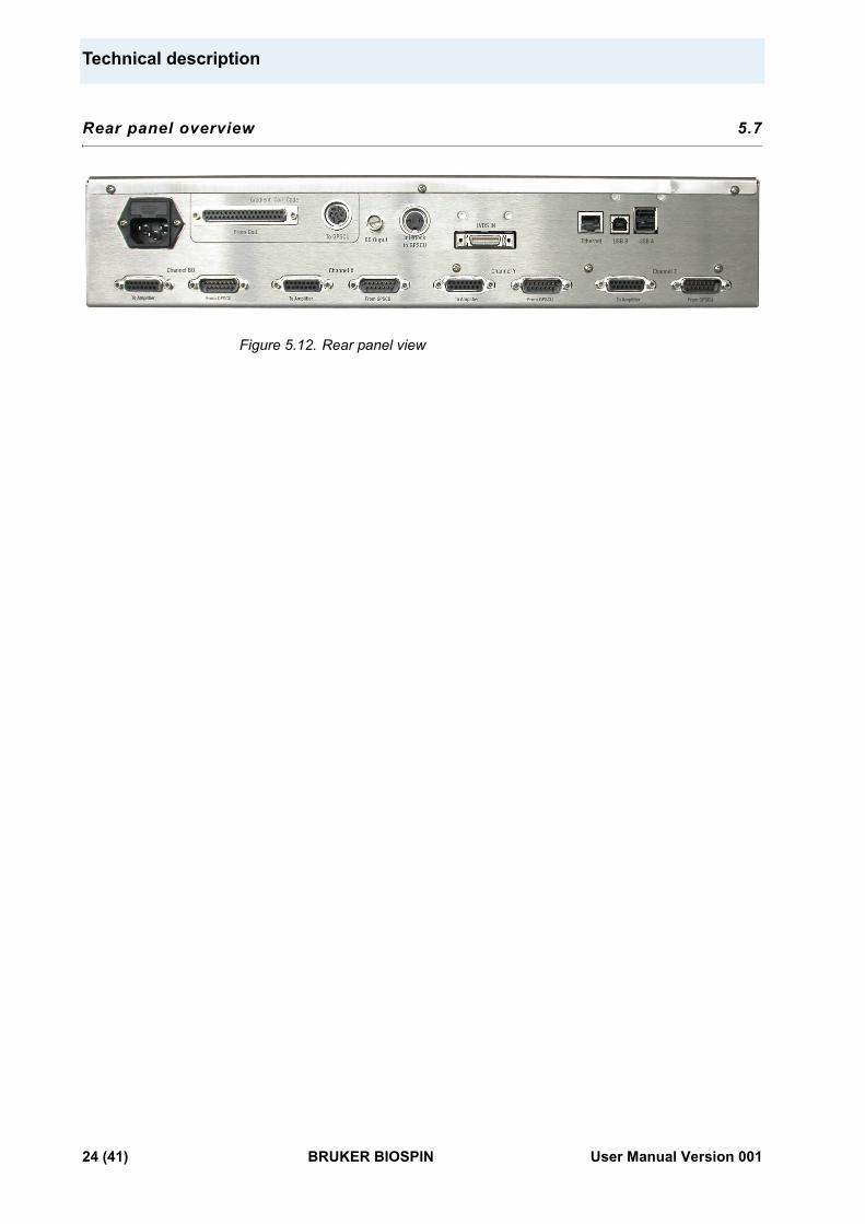
Rear panel overview 5.7
Figure 5.12. Rear panel view
24 (41) BRUKER BIOSPIN User Manual Version 001
6Servicing the GRASI 6
Diagnosis and servicing access to the GRASI unit relies on HTTP, allowing service access with any web browser.
Accessing the GRASI unit 6.1
The GRASI Gradient and Shim Interface Unit is accessible via the CPU-A board with its IP address.
The IP address is given during "cf" by using TOPSPIN 2.xx software under PARAVISION 5 on the workstation.
In case of problems :
• Check the RJ45 cabling between GRASI, Ethernet switch and workstation.
• Check the Ethernet switch power.
• Check if the green LED on the GRASI RJ45 connector lights up.
To access the GRASI unit, type "ha" in TOPSPIN 2.xx and choose the GRASI that should be accessed or start your favourite web browser and type the given IP address as URL.
Some of these pages are only status pages to inform the operator, some other pages allow to modify several parameters of the GRASI unit.
You should get the following start screen.
User Manual Version 001 BRUKER BIOSPIN 25 (41)
Servicing the GRASI
Sub Toolbar Information 6.2
Device Information 6.2.1
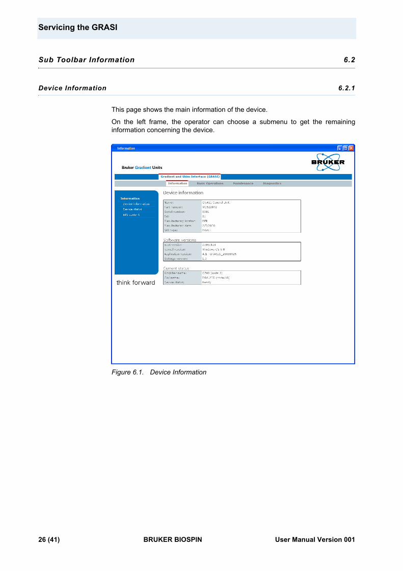
This page shows the main information of the device.
On the left frame, the operator can choose a submenu to get the remaining information concerning the device.
Figure 6.1. Device Information
26 (41) BRUKER BIOSPIN User Manual Version 001
Sub Toolbar Information
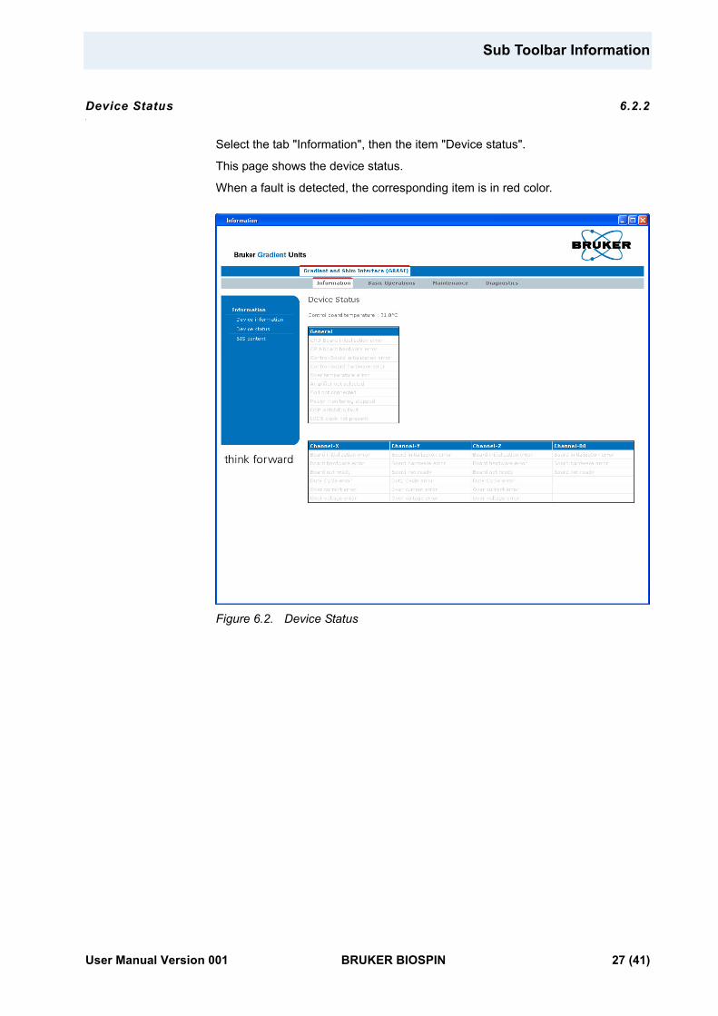
Device Status 6.2.2
Select the tab "Information", then the item "Device status".
This page shows the device status.
When a fault is detected, the corresponding item is in red color.
Figure 6.2. Device Status
User Manual Version 001 BRUKER BIOSPIN 27 (41)
Servicing the GRASI
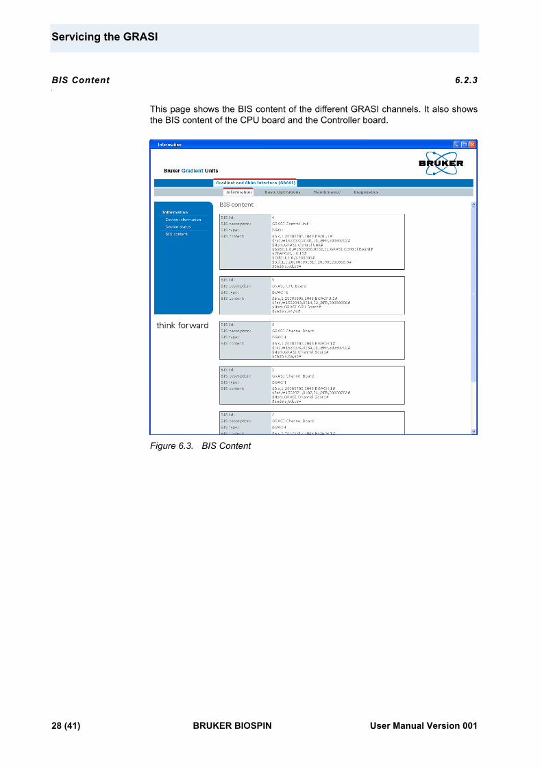
BIS Content 6.2.3
This page shows the BIS content of the different GRASI channels. It also shows the BIS content of the CPU board and the Controller board.
Figure 6.3. BIS Content
28 (41) BRUKER BIOSPIN User Manual Version 001
Sub Toolbar Basic Operations
Sub Toolbar Basic Operations 6.3
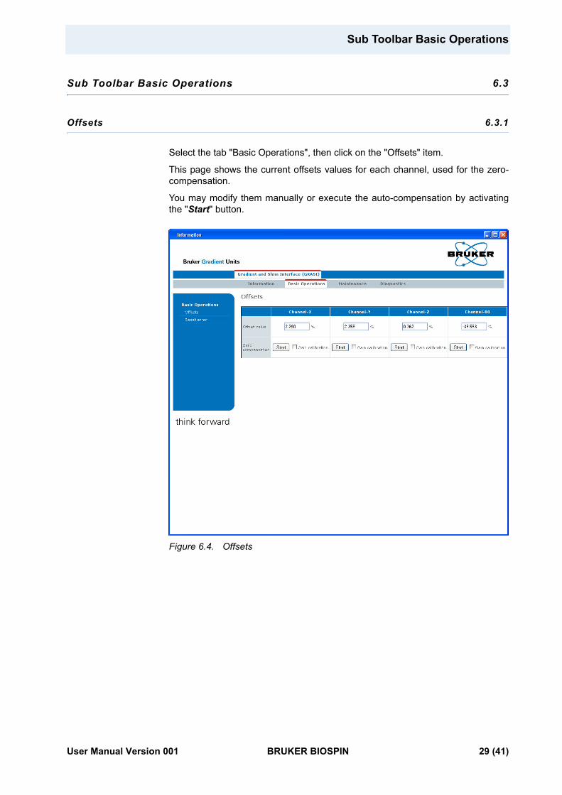
Offsets 6.3.1
Select the tab "Basic Operations", then click on the "Offsets" item.
This page shows the current offsets values for each channel, used for the zero-compensation.
You may modify them manually or execute the auto-compensation by activating the "Start" button.
Figure 6.4. Offsets
User Manual Version 001 BRUKER BIOSPIN 29 (41)
Servicing the GRASI
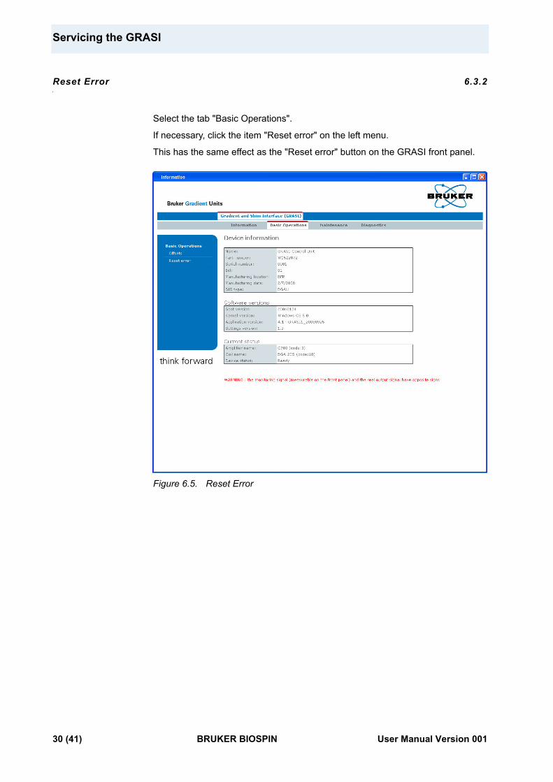
Reset Error 6.3.2
Select the tab "Basic Operations".
If necessary, click the item "Reset error" on the left menu.
This has the same effect as the "Reset error" button on the GRASI front panel.
Figure 6.5. Reset Error
30 (41) BRUKER BIOSPIN User Manual Version 001
Sub Toolbar Maintenance
Sub Toolbar Maintenance 6.4
Settings Update 6.4.1
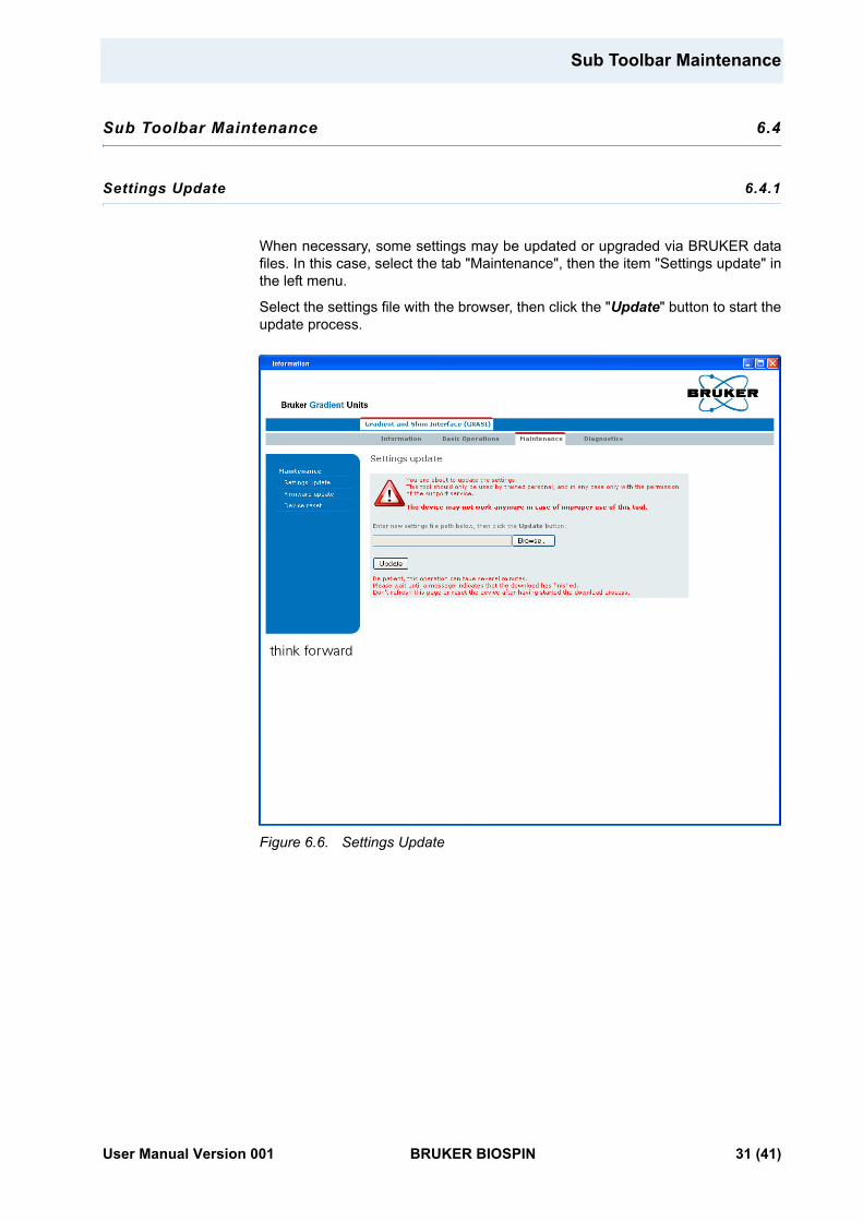
When necessary, some settings may be updated or upgraded via BRUKER data files. In this case, select the tab "Maintenance", then the item "Settings update" in the left menu.
Select the settings file with the browser, then click the "Update" button to start the update process.
Figure 6.6. Settings Update
User Manual Version 001 BRUKER BIOSPIN 31 (41)
Servicing the GRASI
Firmware Update 6.4.2
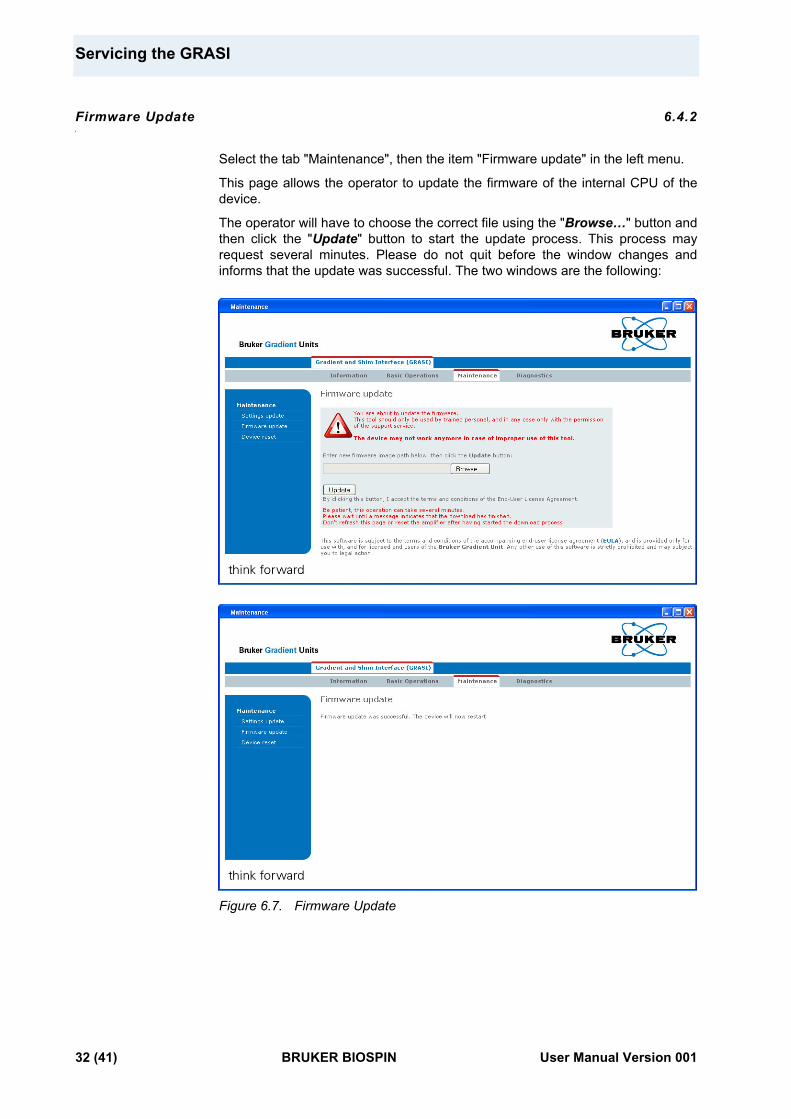
Select the tab "Maintenance", then the item "Firmware update" in the left menu.
This page allows the operator to update the firmware of the internal CPU of the device.
The operator will have to choose the correct file using the "Browse…" button and then click the "Update" button to start the update process. This process may request several minutes. Please do not quit before the window changes and informs that the update was successful. The two windows are the following:
Figure 6.7. Firmware Update
32 (41) BRUKER BIOSPIN User Manual Version 001
Sub Toolbar Maintenance
Device Reset 6.4.3
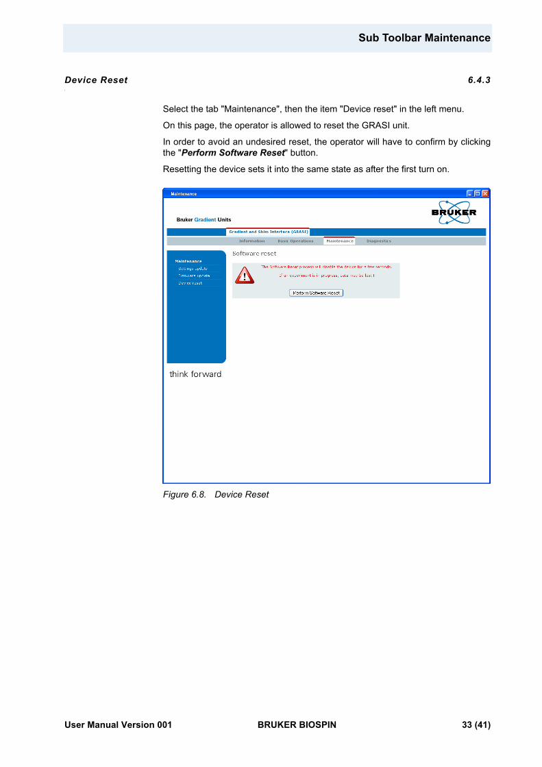
Select the tab "Maintenance", then the item "Device reset" in the left menu.
On this page, the operator is allowed to reset the GRASI unit.
In order to avoid an undesired reset, the operator will have to confirm by clicking the "Perform Software Reset" button.
Resetting the device sets it into the same state as after the first turn on.
Figure 6.8. Device Reset
User Manual Version 001 BRUKER BIOSPIN 33 (41)
Servicing the GRASI
Sub Toolbar Diagnostics 6.5
Event Log 6.5.1
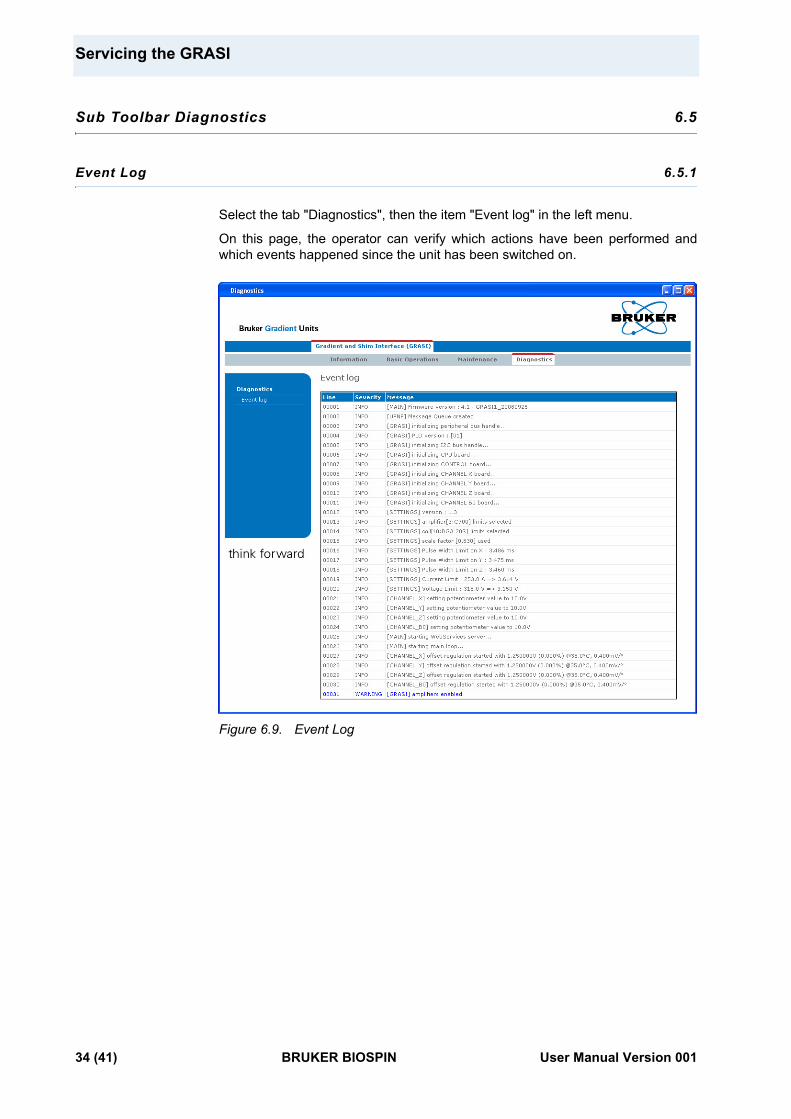
Select the tab "Diagnostics", then the item "Event log" in the left menu.
On this page, the operator can verify which actions have been performed and which events happened since the unit has been switched on.
Figure 6.9. Event Log
34 (41) BRUKER BIOSPIN User Manual Version 001
7Specification 7
General specifications 7.1
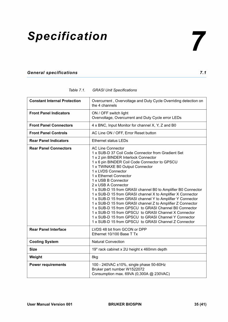
Table 7.1. GRASI Unit Specifications
Constant Internal Protection Overcurrent , Overvoltage and Duty Cycle Overriding detection on the 4 channels
Front Panel Indicators ON / OFF switch lightOvervoltage, Overcurrent and Duty Cycle error LEDs
Front Panel Connectors 4 x BNC, Input Monitor for channel X, Y, Z and B0
Front Panel Controls AC Line ON / OFF, Error Reset button
Rear Panel Indicators Ethernet status LEDs
Rear Panel Connectors AC Line Connector1 x SUB-D 37 Coil Code Connector from Gradient Set1 x 2 pin BINDER Interlock Connector1 x 6 pin BINDER Coil Code Connector to GPSCU1 x TWINAXE B0 Output Connector1 x LVDS Connector1 x Ethernet Connector1 x USB B Connector2 x USB A Connector1 x SUB-D 15 from GRASI channel B0 to Amplifier B0 Connector1 x SUB-D 15 from GRASI channel X to Amplifier X Connector1 x SUB-D 15 from GRASI channel Y to Amplifier Y Connector1 x SUB-D 15 from GRASI channel Z to Amplifier Z Connector1 x SUB-D 15 from GPSCU to GRASI Channel B0 Connector1 x SUB-D 15 from GPSCU to GRASI Channel X Connector1 x SUB-D 15 from GPSCU to GRASI Channel Y Connector1 x SUB-D 15 from GPSCU to GRASI Channel Z Connector
Rear Panel Interface LVDS 48 bit from GCON or DPPEthernet 10/100 Base T Tx
Cooling System Natural Convection
Size 19" rack cabinet x 2U height x 460mm depth
Weight 8kg
Power requirements 100 - 240VAC ±10%, single phase 50-60HzBruker part number W1522072Consumption max. 69VA (0,300A @ 230VAC)
User Manual Version 001 BRUKER BIOSPIN 35 (41)
Specification
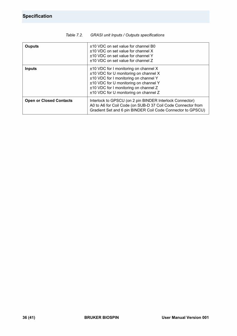
Table 7.2. GRASI unit Inputs / Outputs specifications
Ouputs ±10 VDC on set value for channel B0±10 VDC on set value for channel X±10 VDC on set value for channel Y±10 VDC on set value for channel Z
Inputs ±10 VDC for I monitoring on channel X±10 VDC for U monitoring on channel X±10 VDC for I monitoring on channel Y±10 VDC for U monitoring on channel Y±10 VDC for I monitoring on channel Z±10 VDC for U monitoring on channel Z
Open or Closed Contacts Interlock to GPSCU (on 2 pin BINDER Interlock Connector)A0 to A6 for Coil Code (on SUB-D 37 Coil Code Connector from Gradient Set and 6 pin BINDER Coil Code Connector to GPSCU)
36 (41) BRUKER BIOSPIN User Manual Version 001
Figures
1 Introduction 5Figure 1.1. GRASI Unit diagram ...............................................................................5Figure 1.2. GRASI Gradient and Shim Unit ..............................................................5
2 Safety 7Figure 2.1. Identifying plate ......................................................................................7Figure 2.2. Manufacturer’s nameplate ......................................................................8
3 Installation 11
4 Operation 13Figure 4.1. Functional block diagram ......................................................................13
5 Technical description 17Figure 5.1. Housing dimensions .............................................................................17Figure 5.2. Figure 7 : BNC female connector ..........................................................18Figure 5.3. Red led indicator ..................................................................................19Figure 5.4. Error reset button .................................................................................19Figure 5.5. Sub-D 37 pin female connector ............................................................19Figure 5.6. Sub-D 15 pin male connector ...............................................................20Figure 5.7. Sub-D 15 pin female connector ............................................................21Figure 5.8. Binder 2 pin female connector ..............................................................22Figure 5.9. Binder 6 pin female connector ..............................................................22Figure 5.10.Twinaxe connector ...............................................................................23Figure 5.11.RJ45 8 pin connector ...........................................................................23Figure 5.12.Rear panel view ...................................................................................24
6 Servicing the GRASI 25Figure 6.1. Device Information ...............................................................................26Figure 6.2. Device Status .......................................................................................27Figure 6.3. BIS Content .........................................................................................28Figure 6.4. Offsets .................................................................................................29Figure 6.5. Reset Error ..........................................................................................30Figure 6.6. Settings Update ...................................................................................31Figure 6.7. Firmware Update ..................................................................................32Figure 6.8. Device Reset .......................................................................................33Figure 6.9. Event Log ............................................................................................34
7 Specification 35
User Manual Version 001 BRUKER BIOSPIN 37 (41)

38 (41) BRUKER BIOSPIN User Manual Version 001
Tables
1 Introduction 5
2 Safety 7Table 2.1. Danger ...................................................................................................9
3 Installation 11
4 Operation 13Table 4.1. Troubleshooting ...................................................................................15
5 Technical description 17Table 5.1. BNC female of Monitor X definition .......................................................18Table 5.2. BNC female of Monitor Y definition .......................................................18Table 5.3. BNC female of Monitor Z definition .......................................................18Table 5.4. BNC female of Monitor B0 definition .....................................................18Table 5.5. Sub-D 37 pin female definition ..............................................................20Table 5.6. Sub-D 15 pin male definition ................................................................21Table 5.7. Sub-D 15 pin female definition ..............................................................21Table 5.8. Binder 2 pin female definition ...............................................................22Table 5.9. Binder 6 pin female definition ...............................................................22Table 5.10. Twinaxe definition ................................................................................23Table 5.11. RJ45 8 pin definition .............................................................................23
6 Servicing the GRASI 25
7 Specification 35Table 7.1. GRASI Unit Specifications ....................................................................35Table 7.2. GRASI unit Inputs / Outputs specifications ...........................................36
User Manual Version 001 BRUKER BIOSPIN 39 (41)

40 (41) BRUKER BIOSPIN User Manual Version 001
User Manual Version 001 BRUKER BIOSPIN 41 (41)
End of Document
© B
ruke
r B
ioS
pin
Z318
22
Bruker BioSpin Group
info@bruker�biospin.comwww.bruker�biospin.com
Bruker BioSpin,
your solution partner
Bruker BioSpin provides a world class, market�leadingrange of analysis solutions for your life and materialsscience needs.