Embed Size (px)
Citation preview
Document ID: PLN-2497Revision ID: 1
Effective Date:10/04/10
Plan
Project No. 23747
Graphite Technology Development Plan
Form 412.09 (Rev. 10)
Idaho National Laboratory
GRAPHITE TECHNOLOGY
DEVELOPMENT PLAN
Identifier: Revision: Effective Date:
PLN-2497 1 10/04/10 Page: ii of ix
REVISION LOG
Rev. Date Affected Pages Revision Description
0 October 2007
All Newly issued document
1 10/04/10 All Updates to entire document
Form 412.09 (Rev. 10)
Idaho National Laboratory
GRAPHITE TECHNOLOGY
DEVELOPMENT PLAN
Identifier: Revision: Effective Date:
PLN-2497 1 10/04/10 Page: iii of ix
SUMMARY
The Next Generation Nuclear Plant (NGNP) will be a high temperature gas-cooled reactor (HTGR) with a large graphite core. Graphite physically contains the fuel and comprises the majority of the core volume. Graphite has been used effectively as a structural and moderator material in both research and commercial HTGRs. This development has resulted in graphite being established as a viable structural material for HTGRs.
While the general characteristics necessary for producing nuclear grade graphite are understood, historical “nuclear” grades no longer exist. New grades must therefore be fabricated, characterized, and irradiated to demonstrate that current grades of graphite exhibit acceptable nonirradiated and irradiated properties upon which the thermomechanical design of the structural graphite in NGNP is based. This technology development plan outlines the research and development (R&D) activities and associated rationale necessary to qualify nuclear grade graphite for use within the NGNP reactor.
A commercial graphite-moderated reactor has not been constructed in the world since the 1980s. The last graphite reactor constructed in the United States was the helium-cooled HTGR at Fort St. Vrain, Colorado, in the late 1970s. Japan and China have both constructed experimental (small scale) graphite-moderated high temperature reactors (HTR). New commercial HTGR designs are being developed in the United States and China. The design and construction of a commercial graphite-moderated HTR, one which can be licensed by the NRC, requires the reestablishment of the nuclear graphite supply chain, including reliable coke sources, experienced graphite manufacturers, and the generation of sufficient graphite properties and environmental effects data to facilitate graphite core design and licensing. The acquisition of these quantitative data is the primary goal of the NGNP graphite research and development program.
The irradiation behavior of nuclear graphites has been the subject of research since the 1940s, and the basic mechanisms of irradiation damage are well understood. However, exactly how these in-crystal effects interact with the structure of a given graphite, and subsequently manifest themselves as dimensional and property changes, is less well understood. While the behavior of any given graphite can be predicted in broad terms, the exact magnitude of irradiation induced changes cannot yet be accurately predicted using models based on previous historical data. Since each grade of graphite has a unique structure and texture, its irradiation behavior can be expected to be somewhat different. A further goal of the graphite R&D program is the creation of multiscale models that will enable such predictions in future graphite applications.
Product consistency is achievable in the nuclear graphite industry. The continuous production of graphite fuel sleeves for the United Kingdom’s (UK) advanced gas reactors over the past 30 years has demonstrated this point. To assure the desired attributes are achieved in the newly recreated third generation graphites being developed for the NGNP core, two consensus material specifications have been developed for nuclear graphites; available as American Society for Testing and Materials (ASTM) Standard Specifications. This is the first time a standardized specification for nuclear grade graphite has been established, marking a new level of consistency available for nuclear applications. The achievement of a demonstrated level of consistency (through an unprecedented level of cooperation with graphite manufacturers) is a third goal of the graphite R&D program.
The Graphite Technology Development Plan presents pertinent background information from past graphite reactor experience, other relevant graphite grades, and the state of graphite technology developed for past gas reactors to provide a perspective on what has been achieved previously in this area of research. The technology required to qualify the graphite for use in NGNP is being developed based on
Form 412.09 (Rev. 10)
Idaho National Laboratory
GRAPHITE TECHNOLOGY
DEVELOPMENT PLAN
Identifier: Revision: Effective Date:
PLN-2497 1 10/04/10 Page: iv of ix
the historical graphite fabrication and performance database, the anticipated NGNP graphite design service conditions, and gaps in the fabrication and performance database.
The resultant quantitative data needs are outlined and justified from the perspective of reactor design, reactor performance, or the reactor safety case. The approach allows direct comparison between data needs and the resulting technology development activities. Because there are many variables (multiple reactor designs, multiple graphite types, a range of operating temperatures and fluence, etc.) that can significantly affect the development of graphite technology for the NGNP, a baseline reactor design was chosen to simplify the identification of needed data. The prismatic HTGR design with an outlet temperature between 750 and 950°C was chosen as the baseline reactor parameters. Since these temperatures are well tolerated by the graphite components, a 200°C change in outlet temperature makes little difference in the overall performance or the level of development required for the graphite.
The expected doses and operating temperatures for this baseline reactor design are expected to be fairly moderate and will apply to both prismatic and pebble bed reactor designs. The NGNP irradiation program encompasses the entire anticipated dose limits for prismatic design graphite reflector blocks (up to 6-7 dpa) and approximately 25-30% of the desired dose lifetime for the pebble bed reflector blocks (as high as 20 to 25 dpa). The additional technology development needs to satisfy the increased dose requirements for the pebble bed design are presented separately to provide a more complete understanding of the important differences in the technical requirements for prismatic and pebble-bed HTGRs.
The graphite irradiation program consists of eight irradiations that span the proposed temperature-dose envelope for a prismatic NGNP and the first half of a pebble bed design dose. These irradiations will contain specimens of sufficient size, number, and type to (a) support statistical assessments necessary to capture the inherent variability in graphite; (b) support traditional ASTM requirements for sample analysis; and (c) fully characterize the physical, thermal, and mechanical properties of the irradiated graphite.
The TDP discusses in detail the specific material characterization techniques that will be used to characterize the graphite microstructure and establish the key material properties for both the nonirradiated and irradiated specimens that will be used to support American Society of Mechanical Engineers’ codification of graphite. Factors that can significantly affect the R&D program, such as graphite acquisition, test standard development, and sample preparation (e.g., grain sizes, sample sizes, etc.) are discussed within each characterization section. In addition, the role of the modeling activities from the engineering-scale to the micro or mesoscale to the nanoscale is discussed in the context of this qualification program, and the interrelationships between the experimental and modeling activities are presented to establish a complete picture of the technology development required for NGNP graphite qualification.
Beyond the near-term NGNP graphite qualification program presented here, a more complete evaluation of the processing route and raw material constituent’s influence on graphite behavior is required for full commercialization of the HTGR graphite technology in the long term. This is a long-term strategy outlining the issues of qualifying current and future batches of the selected graphite type, development of future grades of graphite, and appropriate graphite recycling and disposal options. As the graphite raw materials (coke and binder sources) are continuously changing, how these changes are accommodated in future qualification activities must be addressed. In addition, graphite recycle must be considered to reduce the volume and costs of anticipated waste disposal; recycle is considered a long-term strategy and would only be pursued by vendors when large numbers of HTGRs are developed and a nuclear graphite economy is established. The magnitude of the R&D program necessary to establish a
Form 412.09 (Rev. 10)
Idaho National Laboratory
GRAPHITE TECHNOLOGY
DEVELOPMENT PLAN
Identifier: Revision: Effective Date:
PLN-2497 1 10/04/10 Page: v of ix
standard nuclear grade graphite, whether from a new coke source and/or from recycled material for use within any HTGR design, cannot be firmly estimated today, given the current limited knowledge of the linkage between graphite fabrication, material properties, and in-reactor performance. It is anticipated that the work proposed to qualify graphite for the initial NGNP cores will provide the strong technical basis needed to establish a long-term graphite development and qualification program that meets these more ambitious commercialization goals.
Finally, the costs of the NGNP graphite technology development program are presented. The costs are enumerated for experimental, modeling, and mechanism development activities. The additional long-term considerations of recycling and coke source qualification are not included in the final cost estimate, but each topic is discussed since they may have an impact on the other technology development areas in future graphite fabrication and qualification programs.
Form 412.09 (Rev. 10)
Idaho National Laboratory
GRAPHITE TECHNOLOGY
DEVELOPMENT PLAN
Identifier: Revision: Effective Date:
PLN-2497 1 10/04/10 Page: vi of ix
CONTENTS
SUMMARY ................................................................................................................................................. iii
ACRONYMS ............................................................................................................................................... ix
1. INTRODUCTION .............................................................................................................................. 1
2. BACKGROUND ................................................................................................................................ 3 2.1 Radiation Effects on Graphite .................................................................................................. 3
2.1.1 Neutron Damage to the Graphitic Crystal Structures.................................................. 3 2.1.2 Effects Resulting from Irradiation Damage to Graphite ............................................. 4
2.2 Nuclear Grade Graphite ........................................................................................................... 6 2.3 Research and Development of Nuclear Graphite ..................................................................... 7
3. REQUIREMENTS AND SERVICE CONDITIONS ....................................................................... 10 3.1 Physical Parameters of Core .................................................................................................. 10
3.1.1 Fuel Blocks and Pebbles ........................................................................................... 10 3.1.2 Reflector Blocks ........................................................................................................ 10 3.1.3 Peripheral Graphite Components .............................................................................. 11
3.2 Normal and Off-Normal Operating Conditions ..................................................................... 11 3.3 Anticipated Licensing Data Needs ......................................................................................... 12
3.3.1 Research Topics Identified from Nuclear Regulatory Commission PIRT ................ 12 3.3.2 Full Operation or Partial Operating License ............................................................. 13 3.3.3 Full Data Set or Extensive Core Inspection Program ............................................... 13
3.4 Extent of Design Codes and Methodology Required ............................................................. 13
4. MATERIAL PROPERTY NEEDS .................................................................................................. 15 4.1.1 Neutron Irradiation Induced Dimensional Changes .................................................. 15 4.1.2 Neutron Irradiation Induced Thermal Conductivity Changes ................................... 18 4.1.3 Specific Heat Capacity Changes ............................................................................... 19 4.1.4 Emissivity Changes ................................................................................................... 19 4.1.5 Neutron Irradiation-Induced Thermal Expansion Changes ...................................... 20 4.1.6 Neutron Irradiation-Induced Strength Changes ........................................................ 21
5. TECHNOLOGY DEVELOPMENT PLAN ..................................................................................... 23 5.1 Experimental Data .................................................................................................................. 23
5.1.1 Test Sample Preparation ........................................................................................... 24 5.1.2 Nonirradiated Material Testing ................................................................................. 25 5.1.3 Irradiation Experiments ............................................................................................. 25 5.1.4 Material Characterization .......................................................................................... 30
5.2 Multiscale Model Development ............................................................................................. 37 5.2.1 Whole Graphite Core and Component Behavior Models ......................................... 38 5.2.2 Macroscale Materials Behavior Models .................................................................... 38 5.2.3 Microscale/Nanoscale Models .................................................................................. 39
Form 412.09 (Rev. 10)
Idaho National Laboratory
GRAPHITE TECHNOLOGY
DEVELOPMENT PLAN
Identifier: Revision: Effective Date:
PLN-2497 1 10/04/10 Page: vii of ix
6. COSTS AND SCHEDULE .............................................................................................................. 40 6.1 Data Collection Costs ............................................................................................................. 40 6.2 Data Collection Schedules ..................................................................................................... 40
7. LONGER TERM CONSIDERATIONS .......................................................................................... 46 7.1 Graphite Acquisition Plan ...................................................................................................... 46 7.2 Graphite Disposition and Recycle Options ............................................................................ 46
8. REFERENCES ................................................................................................................................. 48
FIGURES Figure 1. Illustration of (a) subatomic particle (neutron) striking a carbon atom in one of the
graphitic basal planes and (b) the resulting ballistic damage to basal planes. .............................. 3
Figure 2. Illustration of (a) interstitial atoms diffusing to lower energy positions between basal planes in the graphite crystal structure and (b) the cluster rearranging itself into a new basal plane. ................................................................................................................................... 4
Figure 3. Typical process steps in the manufacturing of nuclear graphite. ................................................... 6
Figure 4. Volumetric changes in an isotropic graphite illustrating turnaround behavior............................ 16
Figure 5. Schematic diagram illustrating the effects of irradiation temperature on turnaround rates. ............................................................................................................................................ 17
Figure 6. Typical irradiation and temperature induced thermal conductivity changes in reactor graphite, illustrating the small difference in conductivity at high temperatures ......................... 18
Figure 7. Typical changes in linear CTE because of irradiation and temperature. ..................................... 20
Figure 8. Typical irradiation-induced strength changes in reactor graphite as a function of irradiation temperature. .............................................................................................................. 21
Figure 9. Typical irradiation-induced modulus changes in reactor graphite as a function of irradiation temperature. .............................................................................................................. 22
Figure 10. Example typical graphite billet sectioning plan. ........................................................................ 24
Figure 11. Schematic illustration of tensile and compressive loading on tertiary creep response of graphite. ...................................................................................................................................... 27
Figure 12. Schematic diagram illustrating dose and temperature ranges for AGC and HTV experiments. ................................................................................................................................ 27
Figure 13. Internal configuration of AGC experiment. ............................................................................... 29
Figure 14. Schematic diagram illustrating dose and temperature ranges for high dose irradiation experiments. ................................................................................................................................ 30
Figure 15. Estimated irradiation and PIE schedule for AGC experiment. .................................................. 31
Figure 16. Total Graphite Program Costs. FY03–FY09 Total Actuals, — FY10 Actuals thru 9/9/10 — FY11–FY22 Projected Costs based on scheduled activities (includes PM Oversight and Technical Integration) ......................................................................................... 44
Form 412.09 (Rev. 10)
Idaho National Laboratory
GRAPHITE TECHNOLOGY
DEVELOPMENT PLAN
Identifier: Revision: Effective Date:
PLN-2497 1 10/04/10 Page: viii of ix
Figure 17. Master schedule for graphite R&D effort. ................................................................................. 45
TABLES Table 1. Reactor operating conditions. ....................................................................................................... 11
Table 2. Research areas containing the identified PIRT performance phenomena. ................................... 12
Table 3. Material properties of interest. ...................................................................................................... 15
Table 4. Listing of material properties currently being tested or researched in the NGNP program. ......... 31
Table 5. ASTM Standard tests for measuring mechanical properties. ........................................................ 36
Table 6. Estimated costs for graphite R&D ................................................................................................ 41
Table 7. Breakdown of major Graphite R&D costs. ................................................................................... 43
Form 412.09 (Rev. 10)
Idaho National Laboratory
GRAPHITE TECHNOLOGY
DEVELOPMENT PLAN
Identifier: Revision: Effective Date:
PLN-2497 1 10/04/10 Page: ix of ix
ACRONYMS
AGC advanced graphite creep AGR Advanced Gas Reactor ASME American Society of Mechanical Engineers ASTM American Society for Testing and Materials ATR Advanced Test Reactor AVR Albeitsgemeinschaft Versuchsreaktor CT x-ray tomography CTE coefficient of thermal expansion FPY full-power year FSV Fort St. Vrain HFIR high-flux isotope reactor HTGR high temperature gas-cooled reactor HTR High Temperature Reactor (China) HTTR High-Temperature Engineering Test Reactor (Japan) HTV high temperature vessel INL Idaho National Laboratory ISI in-service inspection LLW low-level waste MTR materials test reactor NGNP Next Generation Nuclear Plant NRC Nuclear Regulatory Commission ORNL Oak Ridge National Laboratory PBR pebble-bed reactor PBMR Pebble-Bed Modular Reactor PIE post-irradiation examination PIRT Phenomena Identification and Ranking Table PMR prismatic modular reactor QA Quality Assurance R&D research and development RBMK Reactor Bolshoi Moschnosti Kanalynyi SGL SGL Group, The Carbon Company THTR Thorium Hochtemperatur Reaktor UT ultrasonic testing
Form 412.09 (Rev. 10)
Idaho National Laboratory
GRAPHITE TECHNOLOGY
DEVELOPMENT PLAN
Identifier: Revision: Effective Date:
PLN-2497 1 10/04/10 Page: 1 of 49
1. INTRODUCTION
Graphite has been used effectively as a structural and moderator material in both research and commercial high-temperature, gas-cooled nuclear reactors (Magnox, Advanced Gas Reactor [AGR], Albeitsgemeinschaft Versuchsreaktor [AVR], Reactor Bolshoi Moschnosti Kanalynyi [RBMK], Thorium Hochtemperatur Reaktor [THTR], Fort St. Vrain Reactor [FSV], etc.). This development has resulted in graphite being established as a viable structural material for high temperature gas-cooled reactors (HTGRs). While the general characteristics necessary for producing nuclear grade graphite are understood, historical nuclear grades no longer exist. New grades must therefore be fabricated, characterized, and irradiated to demonstrate that current grades of graphite exhibit acceptable nonirradiated and irradiated properties so that the thermomechanical design of the structural graphite in the Next Generation Nuclear Plant (NGNP) can be validated.
Beyond structural integrity, the reactor lifetime for specific graphite types cannot be established based on the current state of the art; establishing lifetime is complex because of the influence of fabrication and radiation damage on microstructural changes and associated changes in material properties. Lifetime predictions of graphite components with the service demands and reactor operating mode anticipated for NGNP is a practical but much more complex problem than simply determining whether a graphite type is more stable or less stable in an irradiated environment. Graphite properties, such as strain to failure, dimensional change rate, and irradiation dependence of thermal expansion coefficient, can constrain the reactor design by limiting lifetimes for critical components. For example, irradiation-induced dimensional changes to graphite can be severe enough to require limiting the temperature and flux gradients within graphite components or possibly requiring the need for added design features to physically hold components in position over time.
A complicating factor to establishing a qualified fabrication and performance dataset is the inherent variability in the graphite product. Variability within-billet, intrabillets, and batch-to-batch of the graphite must be accounted for in a statistical manner because of its influence on material properties. This variability must also be characterized to enable credible designs and to support the ongoing development of the probabilistic American Society of Mechanical Engineers (ASME) graphite design methodology. The previous Fort St. Vrain design used deterministic performance models for H-327, which was unacceptably conservative given the understanding of graphite at that time, but which would be unacceptably conservative for the NGNP design effort. With our current knowledge, probabilistic performance models can be developed to characterize the new graphite grades for NGNP.
Furthermore, to provide a consistent nuclear grade graphite material for eventual standardization and commercialization of HTGRs, an American Society for Testing and Materials (ASTM) standard specification for isotropic and near-isotropic nuclear graphites (D 7219-08) is being developed along with a standard specification for nuclear graphite suitable for components subjected to low neutron irradiation dose. Additionally, ASME codes and guides for materials selection and qualification, design, fabrication, testing, installation, examination, inspection, and certification will be needed, and thus are under development by the international graphite community. Development of these standards will be necessary to approve future grades of nuclear graphite for new HTGRs.
With this in mind, the overall objectives to qualify the current NGNP graphite for initial operation are as follows:
1. Establish statistical nonirradiated thermomechanical and thermophysical properties
a. Characterize batch-to-batch and billet-to-billet variations (for probabilistic baseline data needs)
Form 412.09 (Rev. 10)
Idaho National Laboratory
GRAPHITE TECHNOLOGY
DEVELOPMENT PLAN
Identifier: Revision: Effective Date:
PLN-2497 1 10/04/10 Page: 2 of 49
2. Establish irradiated thermomechanical and thermophysical properties
3. Develop understanding of life-limiting phenomena at high dose and temperature (e.g., irradiation induced creep)
4. Develop appropriate constitutive relations
5. Establish reliable, predictive thermomechanical finite element models
6. Establish relevant ASTM standards and ASME design rules.
Beyond the initial NGNP graphite objectives, the graphite research and development (R&D) program needs to evaluate the influences of processing route and raw material constituents on graphite behavior as well as recycling and disposal issues. The current world market share for nuclear graphite is extremely small. While graphite manufacturers are willing to produce nuclear grade graphite, the petroleum industry, which produces the raw starting material (specialty coke), is much less interested. The material specifications for specialty coke are much more exacting than what is needed for electrode production, the majority market share for graphite. Since this material’s market share is so small, the coke suppliers have very little financial interest in changing their production process to enable manufacture of these small batches of specialty coke necessary for nuclear graphite production.
As a consequence, there may not be enough specialty coke material for sustained production of nuclear graphite for HTGR applications. In the longer term, a full evaluation of the processing route and raw material constituents’ influence on graphite behavior is required for full commercialization of the HTGR graphite technology. The magnitude of the program necessary to establish a standard nuclear grade graphite for use within any HTGR design is difficult to estimate, given the current limited knowledge of the linkage between fabrication, material properties, and in-reactor performance.
Finally, the lower power density of current HTGRs and the large inner and outer graphite reflector volumes will generate large quantities of low-level waste (LLW) that would have to be disposed of in the absence of recycling. This is complicated by the presence of carbon-14 because of activation of residual nitrogen in the graphite microstructure. Appropriate graphite recycling and disposal options must be considered to reduce the volume and costs of anticipated waste disposal. Two options are currently envisioned: (1) reuse of blocks after heat treatment to anneal out radiation damage, or (2) form new blocks using reconstituted graphite material by crushing and jet milling irradiated blocks to fine powder. Such graphite fabrication methods have been employed before (e.g., BAN graphite). Recycle is considered a long-term strategy and would only be pursued by vendors when large numbers of HTGRs are developed and a nuclear graphite economy established. R&D would be needed to demonstrate that the recycled graphite demonstrated acceptable in-reactor performance. Initial R&R activities to demonstrate the viability of this concept has been initiated as is being conducted through the TRISO Deep Burn Program.
Form 412.09 (Rev. 10)
Idaho National Laboratory
GRAPHITE TECHNOLOGY
DEVELOPMENT PLAN
Identifier: Revision: Effective Date:
PLN-2497 1 10/04/10 Page: 3 of 49
2. BACKGROUND
The basic feasibility of graphite planned for the NGNP has previously been demonstrated in former high-temperature, gas-cooled reactor plants (e.g., DRAGON, Peach Bottom, AVR, THTGR and FSVR). These reactor designs represent two design categories: the pebble-bed reactor (PBR) and the prismatic reactor (PMR). Current commercial examples of potential NGNP candidates are the Gas Turbine-Modular Helium Reactor from General Atomics, High Temperature Reactor concept (ANTARES) from AREVA, and Pebble-bed Modular Reactor (PBMR) from the PBMR Pty, LTD consortium. Furthermore, the Japanese High-Temperature Engineering Test Reactor (HTTR) and Chinese High-Temperature Reactor (HTR-10) are demonstrating the feasibility of the reactor components and materials needed for NGNP (HTTR reached a maximum coolant outlet temperature of 950°C in April 2004). This experience has in large part formed the current understanding of graphite response within a HTGR nuclear environment.
2.1 Radiation Effects on Graphite
Radiation damage to a solid, crystalline microstructure occurs from either ballistic (atomic or subatomic kinetic collisions) or radiological (conversion of radiation-induced electronic excitations to kinetic energy) events. These events can result in significant atomic lattice disruptions, the magnitude of which is significantly dependent upon the bonding energy of the individual atoms.i Generally, ballistic events have higher damage efficiencies per event and thus provide a limiting case for materials exposed to such an environment (a high neutron flux in the HTGR core). The effects of this irradiation exposure on the graphite material properties can be unexpected and significant to the overall performance of the components during reactor service. The significant areas of concern and the general effects on the material properties are outlined below.
2.1.1 Neutron Damage to the Graphitic Crystal Structures
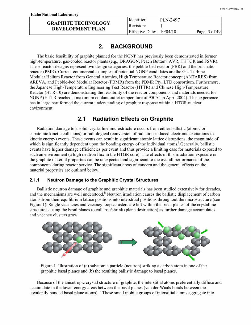
Ballistic neutron damage of graphite and graphitic materials has been studied extensively for decades, and the mechanisms are well understood.ii Neutron irradiation causes the ballistic displacement of carbon atoms from their equilibrium lattice positions into interstitial positions throughout the microstructure (see Figure 1). Single vacancies and vacancy loops/clusters are left within the basal planes of the crystalline structure causing the basal planes to collapse/shrink (plane destruction) as further damage accumulates and vacancy clusters grow.
Figure 1. Illustration of (a) subatomic particle (neutron) striking a carbon atom in one of the graphitic basal planes and (b) the resulting ballistic damage to basal planes.
Because of the anisotropic crystal structure of graphite, the interstitial atoms preferentially diffuse and accumulate in the lower energy areas between the basal planes (van der Waals bonds between the covalently bonded basal plane atoms).iii These small mobile groups of interstitial atoms aggregate into
Form 412.09 (Rev. 10)
Idaho National Laboratory
GRAPHITE TECHNOLOGY
DEVELOPMENT PLAN
Identifier: Revision: Effective Date:
PLN-2497 1 10/04/10 Page: 4 of 49
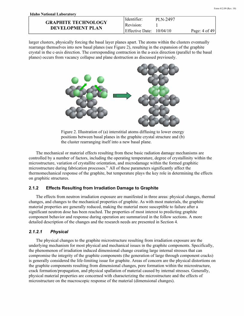
larger clusters, physically forcing the basal layer planes apart. The atoms within the clusters eventually rearrange themselves into new basal planes (see Figure 2), resulting in the expansion of the graphite crystal in the c-axis direction. The corresponding contraction in the a-axis direction (parallel to the basal planes) occurs from vacancy collapse and plane destruction as discussed previously.
Figure 2. Illustration of (a) interstitial atoms diffusing to lower energy positions between basal planes in the graphite crystal structure and (b) the cluster rearranging itself into a new basal plane.
The mechanical or material effects resulting from these basic radiation damage mechanisms are controlled by a number of factors, including the operating temperature, degree of crystallinity within the microstructure, variation of crystallite orientation, and microdamage within the formed graphitic microstructure during fabrication processes.iv All of these parameters significantly affect the thermomechanical response of the graphite, but temperature plays the key role in determining the effects on graphitic structures.
2.1.2 Effects Resulting from Irradiation Damage to Graphite
The effects from neutron irradiation exposure are manifested in three areas: physical changes, thermal changes, and changes to the mechanical properties of graphite. As with most materials, the graphite material properties are generally reduced, making the material more susceptible to failure after a significant neutron dose has been reached. The properties of most interest to predicting graphite component behavior and response during operation are summarized in the follow sections. A more detailed description of the changes and the research needs are presented in Section 4.
2.1.2.1 Physical
The physical changes to the graphite microstructure resulting from irradiation exposure are the underlying mechanism for most physical and mechanical issues in the graphite components. Specifically, the phenomenon of irradiation induced dimensional change creating large internal stresses that can compromise the integrity of the graphite components (the generation of large through component cracks) is generally considered the life-limiting issue for graphite. Areas of concern are the physical distortions on the graphite components resulting from dimensional changes, pore formation within the microstructure, crack formation/propagation, and physical spallation of material caused by internal stresses. Generally, physical material properties are concerned with characterizing the microstructure and the effects of microstructure on the macroscopic response of the material (dimensional changes).
Form 412.09 (Rev. 10)
Idaho National Laboratory
GRAPHITE TECHNOLOGY
DEVELOPMENT PLAN
Identifier: Revision: Effective Date:
PLN-2497 1 10/04/10 Page: 5 of 49
2.1.2.2 Thermal
Thermal material properties are critical for protecting the fuel particles during off-normal events as well as for predicting thermally induced stress states within solid graphite components (reflector blocks). Degradation in thermal properties—conductivity, specific heat, emissivity, and coefficient of thermal expansion (CTE)—will significantly impact the ability of the graphite to both absorb energy and transfer the heat load out of the core region during an off-normal event. Without adequate removal of the heat, fuel particle centerline temperatures will exceed the design limits, resulting in unacceptable numbers of particle failures and radiation release levels. In addition, thermally induced stresses can be exacerbated between and within graphite blocks with significantly altered thermal properties. Elevated stress levels can exceed the structural strength of the graphite blocks, resulting in cracking, spallation, and structural instability.
The oxidation rate of graphite during normal and off-normal operations is required to determine the effect of oxidation on the specific graphite properties as well as the entire core performance. There are two primary concerns resulting from oxidation; failure of individual graphite blocks (because of strength and thermal conductivity reduction as a result of pore formation and growth) and general core geometry configuration issues (the entire core fails because of acute oxidation and catastrophic graphite failure). Other issues affected by oxidation include degradation of the thermal emissivity, changes to CTE (because of pore formation), and changes to irradiation creep rate. To accurately predict the oxidation rate and the effects of oxidation on the graphite components, kinetic and diffusion controlled oxidation models resulting from experimental data will be required to predict weight loss in specific areas of the core. It is generally expected that the damage will be limited and that core geometry remains intact; however, some data will be required to confirm this assessment.
Additionally, based on regulatory requirements, thermal and mechanical testing of previously oxidized material will need to be performed to determine the chronic effects oxidation may have on graphite material properties. Mechanical and thermal properties will be investigated from both acute and chronic oxidized material. The affects resulting from chemical and physical (pores) differences for each graphite type will be required.
2.1.2.3 Mechanical
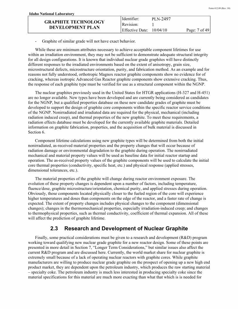
The graphite single crystal is highly anisotropic because of strong covalent bonds between the carbon atoms in the basal plane and weak van der Waals bonds between the basal planes. This anisotropy is transferred to the filler coke particles and also to the crystalline regions in the binder phase. Thus, the mechanical and physical properties of graphite vary within a billet because of texture introduced during forming and thermal processing. Moreover, there is statistical variability in the properties between billets within the same batches and between batches because of variations in raw materials, formulations, and processing conditions. Accurate characterization of the mechanical properties is fundamental to determining the induced and applied stresses to the graphite components. Specifically, properties such as the elastic modulus, compressive and tensile strength, the shear strength to predict fracture probability, and multiaxial failure criteria because of the complex stress states, both internal and external, on the components. An accurate measurement of the mechanical properties along with the induced internal and external stresses from the physical changes to the graphite are needed to determine the component’s ability to withstand the imposed loads and service conditions during operation.
Strain relief of induced stresses (irradiation creep) within irradiated graphite microstructures allows the graphite to withstand irradiation damage resulting from irradiation induced dimensional changes. However, past turnaround (where dimensional contraction switches to dimensional swelling) with
Form 412.09 (Rev. 10)
Idaho National Laboratory
GRAPHITE TECHNOLOGY
DEVELOPMENT PLAN
Identifier: Revision: Effective Date:
PLN-2497 1 10/04/10 Page: 6 of 49
accommodating microcracks closed the dimensional changes are very rapid, resulting primarily from the formation of pores within the microstructure. This rapid pore formation in the microstructure will significantly alter most of the material properties of interest in nuclear graphite during long-term exposure (thermal, mechanical, and even physical). The graphite performance and changes to the material microstructure and properties during long-term exposure must be characterized and understood to validate the design and establish accurate lifetimes for new graphite types.
Finally, there is a concern that wear on the pebbles during movement can generate dust, which will act as a means for transporting fission products during loss of depressurzation of the primary circuit. This is primarily a concern for the pebble bed design with the moveable core of that design making this issue viable. To determine the amount of dust to be generated, the tribological properties of the graphite must be determined.
2.2 Nuclear Grade Graphite
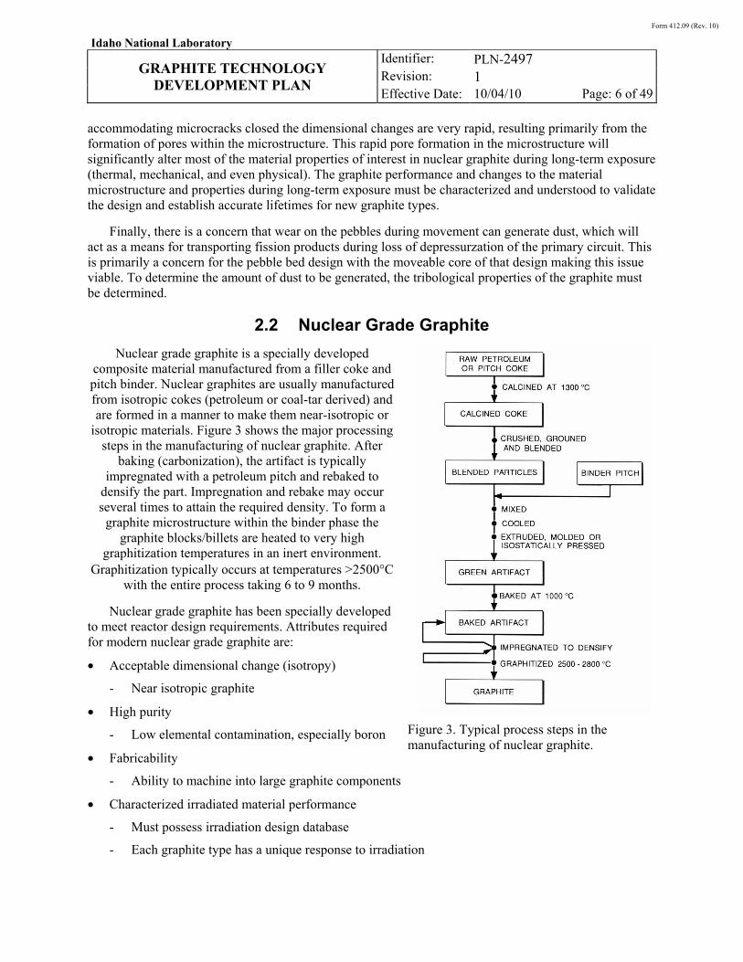
Nuclear grade graphite is a specially developed composite material manufactured from a filler coke and pitch binder. Nuclear graphites are usually manufactured from isotropic cokes (petroleum or coal-tar derived) and are formed in a manner to make them near-isotropic or
isotropic materials. Figure 3 shows the major processing steps in the manufacturing of nuclear graphite. After
baking (carbonization), the artifact is typically impregnated with a petroleum pitch and rebaked to
densify the part. Impregnation and rebake may occur several times to attain the required density. To form a
graphite microstructure within the binder phase the graphite blocks/billets are heated to very high
graphitization temperatures in an inert environment. Graphitization typically occurs at temperatures >2500°C
with the entire process taking 6 to 9 months.
Nuclear grade graphite has been specially developed to meet reactor design requirements. Attributes required for modern nuclear grade graphite are:
• Acceptable dimensional change (isotropy)
- Near isotropic graphite
• High purity
- Low elemental contamination, especially boron
• Fabricability
- Ability to machine into large graphite components
• Characterized irradiated material performance
- Must possess irradiation design database
- Each graphite type has a unique response to irradiation
Figure 3. Typical process steps in the manufacturing of nuclear graphite.
Form 412.09 (Rev. 10)
Idaho National Laboratory
GRAPHITE TECHNOLOGY
DEVELOPMENT PLAN
Identifier: Revision: Effective Date:
PLN-2497 1 10/04/10 Page: 7 of 49
- Graphite of similar grade will not have exact behavior.
While these are minimum attributes necessary to achieve acceptable component lifetimes for use within an irradiation environment, they may not be sufficient to demonstrate adequate structural integrity for all design configurations. It is known that individual nuclear grade graphites will have distinctly different responses to the irradiated environments based on the extent of anisotropy, grain size, microstructural defects, microstructure orientation, purity, and fabrication method. As an example and for reasons not fully understood, orthotropic Magnox reactor graphite components show no evidence for of cracking, whereas isotropic Advanced Gas Reactor graphite components show extensive cracking. Thus, the response of each graphite type must be verified for use as a structural component within the NGNP.
The nuclear graphites previously used in the United States for HTGR applications (H-327 and H-451) are no longer available. New types have been developed and are currently being considered as candidates for the NGNP, but a qualified properties database on these new candidate grades of graphite must be developed to support the design of graphite core components within the specific reactor service conditions of the NGNP. Nonirradiated and irradiated data are required for the physical, mechanical (including radiation induced creep), and thermal properties of the new graphite. To meet these requirements, a radiation effects database must be developed for the currently available graphite materials. Detailed information on graphite fabrication, properties, and the acquisition of bulk material is discussed in Section 6.
Component lifetime calculations using new graphite types will be determined from both the initial nonirradiated, as-received material properties and the property changes that will occur because of radiation damage or environmental degradation to the graphite during operation. The nonirradiated mechanical and material property values will be used as baseline data for initial reactor startup and operation. The as-received property values of the graphite components will be used to calculate the initial core thermal properties (conductivity, specific heat, etc.) and physical response (applied stresses, dimensional tolerances, etc.).
The material properties of the graphite will change during reactor environment exposure. The evolution of these property changes is dependent upon a number of factors, including temperature, fluence/dose, graphite microstructure/orientation, chemical purity, and applied stresses during operation. Obviously, those components located physically closer to the fueled region of the core will experience higher temperatures and doses than components on the edge of the reactor, and a faster rate of change is expected. The extent of property changes includes physical changes to the component (dimensional changes); changes in the thermomechanical properties, especially irradiation-induced creep; and changes to thermophysical properties, such as thermal conductivity, coefficient of thermal expansion. All of these will affect the prediction of graphite lifetime.
2.3 Research and Development of Nuclear Graphite
Finally, some practical considerations must be given to a research and development (R&D) program working toward qualifying new nuclear grade graphite for a new reactor design. Some of these points are presented in more detail in Section 7, “Longer Term Considerations,” but similar issues also affect the current R&D program and are discussed here. Currently, the world market share for nuclear graphite is extremely small because of a lack of operating nuclear reactors with graphite cores. While graphite manufacturers are willing to produce nuclear grade graphite on the prospect of opening up a new high end product market, they are dependent upon the petroleum industry, which produces the raw starting material – specialty coke. The petroleum industry is much less interested in producing specialty coke since the material specifications for this material are much more exacting than what that which is is needed for
Form 412.09 (Rev. 10)
Idaho National Laboratory
GRAPHITE TECHNOLOGY
DEVELOPMENT PLAN
Identifier: Revision: Effective Date:
PLN-2497 1 10/04/10 Page: 8 of 49
electrode production, the majority market share for graphite. Since the market share for specialty coke is so small, the coke suppliers have very little financial interest in changing their production process to enable manufacture of these small batches of specialty coke necessary for nuclear graphite production. This presents a problem with qualifying a new graphite for nuclear applications, as there may not be enough specialty coke material needed for sustained production of this selected nuclear graphite for HTGR applications over a long period of time. This problem will persist until a viable fleet of HTGR nuclear reactors has been established.
In addition, the coke material (and coal-tar binder material) is a geological material. This means that the original carbon-based material that forms the basic building blocks making up graphite was organic material deposited over millions of years and is currently extracted in the form of carbon-based oil or coal. As geological materials that are formed from deposits over millions of years the material was constantly changing as the deposited material changed over time. The general understanding is that as the material is extracted from deeper in the mine, or oil well, that the material will change. Thus, the coke and binder material source is constantly changing over time, which affects the microstructure of the manufactured graphite and ultimately the irradiation behavior and performance. This potential shortage of stable coke sources has been addressed in much more detail within the NGNP Graphite Selection and Acquisition Strategy. v
Finally, DOE and the U.S. government is not the actual customer for any nuclear grade graphite that may be selected for eventual use within the NGNP. The reactor owner and reactor vender will be selecting a graphite type that best fits their reactor design. They may require small or moderate changes to the as-fabricated material properties of the selected graphite - they may require the graphite vendor to produce a specific graphite but with a higher strength value. This implies that a reactor vendor may select a graphite type similar to that which has been tested by the Graphite R&D program. While the actual nonirradiated and irradiated material performance resulting from these small changes to the material properties may not change significantly, the quality assurance (QA) aspects of the R&D program may be affected because the material recipe is changing.
None of these issues (either the coke source limitations or the QA questions) are particularly significant. First, the graphite manufacturers are especially adept at making minor changes to the fabrication formulae to account for changes to the coke supply. As stated previously, the raw materials are ever changing and the vendors are knowledgeable on how to manipulate the fabrication process to keep the performance of the finished graphite product consistent. However, they are not as knowledgeable concerning irradiation induced changes, and therefore the R&D program must provide data that can assist in the formulae changes in the future. This is a main component of the Advanced Graphite Creep (AGC) program, in which multiple graphite types are being irradiated (e.g., graphite types with large grain to fine grain, petroleum verses coal-based coke, isostatic pressed or extruded) in order to understand the changes to the overall performance of the graphite during irradiation. This is also an important aspect of the mechanism and testing development activities that the Graphite R&D program is currently participating in with research universities and foreign research programs (the International Atomic Energy Agency and Generation IV International Forum programs). Understanding the changes to the graphite performance based upon the differences in fabrication is a significant aspect of the program.
Finally, from a QA aspect, it can be considered that the “exact” graphite types to be used in a NGNP reactor core may not be the ones tested in this program. However, the graphite types currently being tested are very similar to what will actually be used and from a material performance measure are effectively the same. This QA question has been of some concern since QA requires that a material not change significantly from testing to implementation. The debate has centered upon what could be considered significant changes to the material. As stated, from a material performance perspective the

Form 412.09 (Rev. 10)
Idaho National Laboratory
GRAPHITE TECHNOLOGY
DEVELOPMENT PLAN
Identifier: Revision: Effective Date:
PLN-2497 1 10/04/10 Page: 9 of 49
changes will be very small and the tests should well envelope the expected performance of any new graphite that would eventually be used. It is expected that a final proof test may be required by the reactor vendor/owner to demonstrate that any changes made to the fabrication actually do impart only minor changes to the graphite performance. In addition, the mechanism and testing development activities mentioned previously will assist in demonstrating that the changes are indeed minor. For full commercialization of the HTGR graphite technology in the long term, a more complete evaluation of the processing route and raw material (e.g., coke source) constituent’s influence on graphite behavior is required.
Form 412.09 (Rev. 10)
Idaho National Laboratory
GRAPHITE TECHNOLOGY
DEVELOPMENT PLAN
Identifier: Revision: Effective Date:
PLN-2497 1 10/04/10 Page: 10 of 49
3. REQUIREMENTS AND SERVICE CONDITIONS
Reactor design considerations, design service operating conditions, and reactor safety requirements are key considerations in determining the allowable change in material properties of nuclear graphite. Physical parameters such as component size, geometry, and machining may require specific billet sizes and grain sizes. Operating conditions will specify expected fluence/dose, temperatures, and initial imposed loads upon the graphite components. Finally, safety considerations may require additional material property measurements, such as oxidation rate, properties after oxidation, wear/friction for dust formation, and post-irradiation thermomechanical and thermophysical properties.
As an example, fuel blocks for the PMR design have a number of fuel and coolant channel holes drilled axially down the length of the block. The pitch between these holes can be quite small leaving a relatively thin graphite webbing. If the graphite grain size is large, the webbing may only have one to two grains between channels. One to two grains of a material will not represent the true properties of a material, thus providing uncertainty in irradiation stability and strength of the channel webbing. It is therefore necessary to select a small-grained graphite that can provide 10 or more grains (at least) between the channels. Pebble fuel has no such machining constraints and can easily accommodate large grain sized graphite. A different graphite type can be used if a PBR design is selected for NGNP.
3.1 Physical Parameters of Core
3.1.1 Fuel Blocks and Pebbles
A compromise between superior material properties and material cost is an important consideration in selecting a nuclear grade graphite for the NGNP graphite program. The Japanese IG-110 graphite with its very small grain size and isotropic microstructure shows excellent nuclear response (high stability) and is considered one of the best commercially available nuclear graphites on the market. However, it is prohibitively expensive, and the fabrication technique is exacting. As a consequence, the Japanese only use IG-110 in limited applications within the harshest nuclear environments (inner core components). These issues have led the Japanese to evaluate graphites different than IG-110 for future HTGR applications. Similar logic is being applied to the graphite selection for the NGNP program, in which where in the service conditions and applications for each component are evaluated and a suitable nuclear graphite is selected for optimal performance within those particular parameters.
3.1.2 Reflector Blocks
A similar rationale is used when determining the parameters required for graphite blocks used in the reflector regions. The continuous refueling design of the PBR allows it to operate without having to shut down for periodic refueling. However, the stationary reflector blocks do sustain radiation damage and must be replaced periodically. For economic reasons, a PBR is operated continuously for as long as possible, forcing the reflector blocks to withstand much longer times and higher doses than prismatic reflector blocks are expected to withstand.
Most pebble-bed designs would have the reactor to operate for at least 20 years before having to defuel the entire core to replace the reflector blocks. At expected NGNP fluence levels, this can equate to doses as high as 25 dpa, which is well past turnaround, even for the most stable nuclear graphites. Such a high dose level will require careful analysis of the irradiation response of the graphite selected for reflector block use. For purely economic reasons, replacing the reflector blocks within a prismatic core as infrequently as possible is desirable. The more stable the response of the graphite blocks is to irradiation,
Form 412.09 (Rev. 10)
Idaho National Laboratory
GRAPHITE TECHNOLOGY
DEVELOPMENT PLAN
Identifier: Revision: Effective Date:
PLN-2497 1 10/04/10 Page: 11 of 49
the lower the costs for replacement material and less downtime for the reactor. These economic considerations are important factors for determining the appropriate graphite for the NGNP reactor.
3.1.3 Peripheral Graphite Components
Graphite components outside of the central core region, including permanent reflector blocks, core support columns/structures, and others surrounding the core, will receive considerably lower doses and operate at much lower temperatures. As a result, the concern is not necessarily irradiation stability but environmental attack or abnormally large stress states on the graphite components. This can dramatically alter the fracture strength, compressive strength, changes to thermal conductivity, and/or emissivity resulting in structural integrity concerns and loss of efficient reactor heat flow.
Oxidation rates, both acute and long-term chronic degradation, are of specific concern during operation. Oxidation of graphitic components can lead to a loss of strength and may affect the thermomechanical and thermophysical properties. Further, generation of dust and small particulates from wear and friction can provide a means for spreading contamination when the coolant is released from the primary system. Finally, seismic and large applied loads may exceed the strength of compromised graphite (such as the support columns) causing failure in critical core components. Material properties for all graphite components must be characterized to determine the response of the reactor core and support structures under normal and off-normal conditions.
3.2 Normal and Off-Normal Operating Conditions
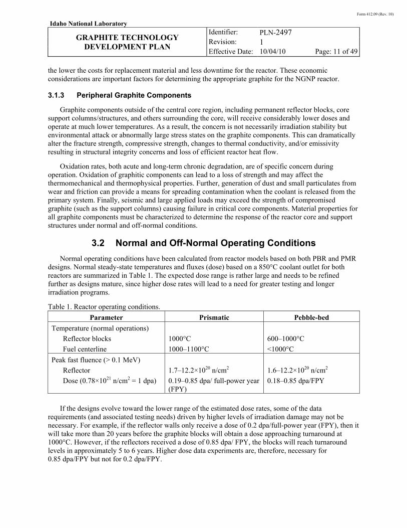
Normal operating conditions have been calculated from reactor models based on both PBR and PMR designs. Normal steady-state temperatures and fluxes (dose) based on a 850°C coolant outlet for both reactors are summarized in Table 1. The expected dose range is rather large and needs to be refined further as designs mature, since higher dose rates will lead to a need for greater testing and longer irradiation programs.
Table 1. Reactor operating conditions.
Parameter Prismatic Pebble-bed
Temperature (normal operations)
Reflector blocks
Fuel centerline
1000°C
1000–1100°C
600–1000°C
<1000°C
Peak fast fluence (> 0.1 MeV)
Reflector
Dose (0.78×10²¹ n/cm2 = 1 dpa)
1.7–12.2×10²⁰ n/cm2
0.19–0.85 dpa/ full-power year (FPY)
1.6–12.2×10²⁰ n/cm2
0.18–0.85 dpa/FPY
If the designs evolve toward the lower range of the estimated dose rates, some of the data requirements (and associated testing needs) driven by higher levels of irradiation damage may not be necessary. For example, if the reflector walls only receive a dose of 0.2 dpa/full-power year (FPY), then it will take more than 20 years before the graphite blocks will obtain a dose approaching turnaround at 1000°C. However, if the reflectors received a dose of 0.85 dpa/ FPY, the blocks will reach turnaround levels in approximately 5 to 6 years. Higher dose data experiments are, therefore, necessary for 0.85 dpa/FPY but not for 0.2 dpa/FPY.
Form 412.09 (Rev. 10)
Idaho National Laboratory
GRAPHITE TECHNOLOGY
DEVELOPMENT PLAN
Identifier: Revision: Effective Date:
PLN-2497 1 10/04/10 Page: 12 of 49
Since turnaround is a function of temperature as well as dose, this also applies to lower operating temperatures within the reactor.
3.3 Anticipated Licensing Data Needs
3.3.1 Research Topics Identified from Nuclear Regulatory Commission PIRT
The Nuclear Regulatory Commission (NRC) Phenomena Identification and Ranking Table (PIRT) process was applied to the issue of nuclear grade graphite for the moderator and structural components of an NGNP. An international group of graphite experts used this process to identify and rank, by importance, any phenomena that may adversely affect the performance of a nuclear reactor during both normal and off-normal operation. Material property changes as well as material response during accident conditions are considered during this process.
A specified PIRT has been developed to identify and rank phenomena affecting the performance of graphite components in a nuclear reactor. The initial ranked phenomena anticipated for graphite components within the NGNP core have been established in the NRC PIRT report, NUREG/CR-6944, Vol. 1-6.vi
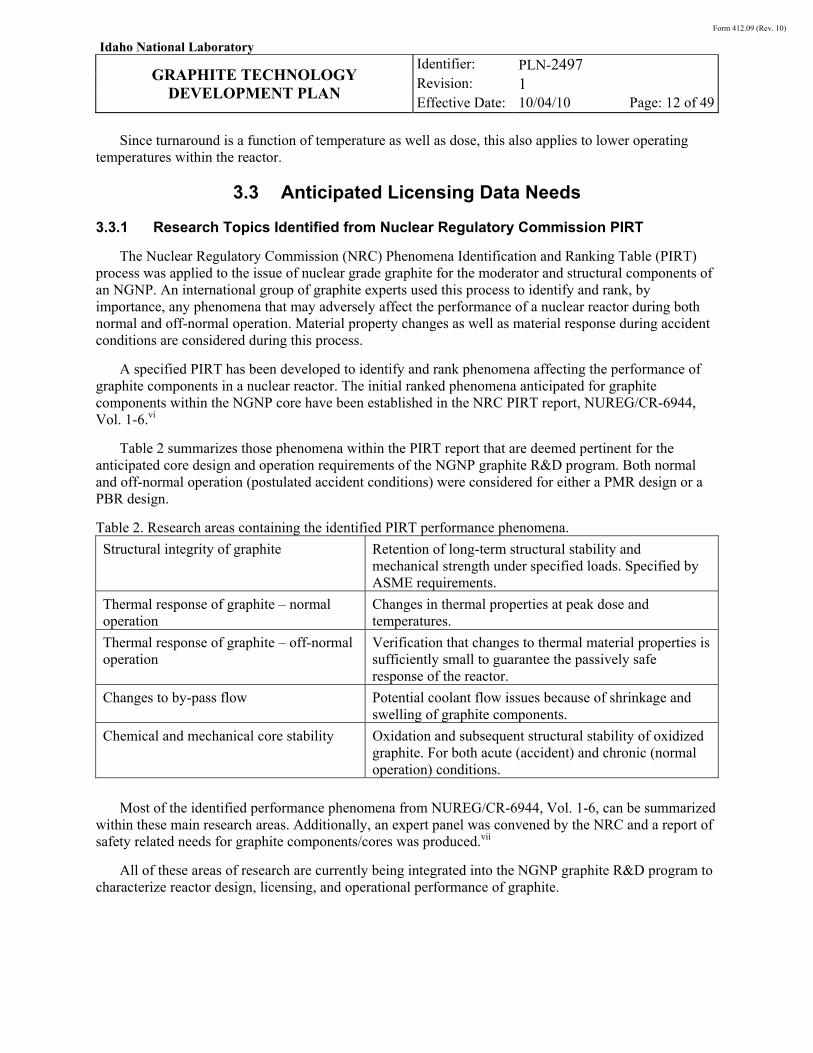
Table 2 summarizes those phenomena within the PIRT report that are deemed pertinent for the anticipated core design and operation requirements of the NGNP graphite R&D program. Both normal and off-normal operation (postulated accident conditions) were considered for either a PMR design or a PBR design.
Table 2. Research areas containing the identified PIRT performance phenomena.
Structural integrity of graphite Retention of long-term structural stability and mechanical strength under specified loads. Specified by ASME requirements.
Thermal response of graphite – normal operation
Changes in thermal properties at peak dose and temperatures.
Thermal response of graphite – off-normal operation
Verification that changes to thermal material properties is sufficiently small to guarantee the passively safe response of the reactor.
Changes to by-pass flow Potential coolant flow issues because of shrinkage and swelling of graphite components.
Chemical and mechanical core stability Oxidation and subsequent structural stability of oxidized graphite. For both acute (accident) and chronic (normal operation) conditions.
Most of the identified performance phenomena from NUREG/CR-6944, Vol. 1-6, can be summarized within these main research areas. Additionally, an expert panel was convened by the NRC and a report of safety related needs for graphite components/cores was produced.vii
All of these areas of research are currently being integrated into the NGNP graphite R&D program to characterize reactor design, licensing, and operational performance of graphite.
Form 412.09 (Rev. 10)
Idaho National Laboratory
GRAPHITE TECHNOLOGY
DEVELOPMENT PLAN
Identifier: Revision: Effective Date:
PLN-2497 1 10/04/10 Page: 13 of 49
3.3.2 Full Operation or Partial Operating License
The NGNP program may elect to apply for a partial (or demonstration) license to the NRC for this first reactor. The assumption is that a fully qualified graphite will not be required for use within a demonstration reactor and the program will not need to perform some of the higher dose experiments to support a full operating license before start-up can occur. In addition, the demonstration plant may not operate at full design power for some initial period of time, thus producing less fluence and lower temperatures than expected for full power operation.
As a result, the regulator may be satisfied with some or only part of the data needed for full qualification effectively giving the program more time to gather the required data for full licensing of the graphite. Experiments necessitating longer times and higher irradiation dose can be delayed until the reactor will actually be operated at the higher temperatures and fluences expected at full design power.
3.3.3 Full Data Set or Extensive Core Inspection Program
Rather than fully characterizing the graphite before building the reactor, the NGNP program may elect to have an extensive core in-service inspection (ISI) program. As stated previously, one can be relatively certain that any of the current nuclear graphites (isotropic, pure nuclear grade graphite) will be stable for a short period of time within an HTGR core. However, an extensive core inspection program will be required to assure the NRC (and other regulatory groups) that the graphite is behaving as predicted since there will be insufficient verification data. In addition, since an ISI program can only monitor a fraction of the core, there will need to be additional verification data in the form of a characterization program (nonirradiated and irradiated material) conducted in parallel while the reactor is operating. The characterization program can be limited in scope since a large portion of the verification resides with the core inspection.
The PBMR reactor in South Africa pursued just such a defense-in-depth core inspection approach. Using the NBG-18 nuclear grade graphite from SGL Group, Inc., the PBMR project intended to build the reactor core without a complete database of material properties. The PBMR project was to supplement some nonirradiation material properties for NBG-18 with extensive in-core inspections during the first 4 to 5 years of operation. Meanwhile, an irradiation program specifically characterizing NBG-18 irradiation response would be conducted in parallel to provide a more comprehensive database for use in developing the long-range goal of a predictive model for graphite behavioral response.
3.4 Extent of Design Codes and Methodology Required
To provide consistent nuclear grade graphite for the eventual commercialization of HTGRs, two ASTM specifications have been written and approved. These ASTM specifications are designated D7219, “Standard Specification for Isotropic and Near-isotropic Nuclear Graphites,” and D7301, “Standard Specification for Nuclear Graphite Suitable for Components Subjected to Low Neutron Irradiation Dose.”
ASME, Section III (Nuclear), Subgroup for Graphite Core Components (SG-GCC) has developed new rules for the construction of graphite cores for HTGRs. These rules have been approved by ASME and will be published in 2011 in the newly created Division 5 of the Section III of the ASME Boiler & Pressure Vessel Code. The new code addresses both the general requirements (Part GA) and technical requirements (Part GB) for the construction of graphite cores. The subsection of the new code containing technical requirements for graphite has the requirements reported in several Articles:
Article 1000 – Introduction
Form 412.09 (Rev. 10)
Idaho National Laboratory
GRAPHITE TECHNOLOGY
DEVELOPMENT PLAN
Identifier: Revision: Effective Date:
PLN-2497 1 10/04/10 Page: 14 of 49
Article 2000 – Materials
Article 3000 – Design
Article 4000 – Machining, Examination and Testing
Article 5000 – Installation and Examination
Mandatory Appendix GB I – Graphite Materials Specifications (co-opted from ASTM)
Mandatory Appendix GB II – Requirements for Preparation of a Material Data Sheet
Mandatory Appendix GB III – Requirements for Generation of Design Data for Graphite Grades.
Subgroup Graphite Core Components is currently in the process of realigning the Graphite code to better match the structure of the existing metal related codes. Moreover, new rules are being developed for the use of high temperature composite materials and will also eventually be published in ASME B&PV Code, Sect. III, Div. 5, as subparts HA, Subpart C (General Requirements) and HH, Subpart B (Composite Construction Rules).
Form 412.09 (Rev. 10)
Idaho National Laboratory
GRAPHITE TECHNOLOGY
DEVELOPMENT PLAN
Identifier: Revision: Effective Date:
PLN-2497 1 10/04/10 Page: 15 of 49
4. MATERIAL PROPERTY NEEDS
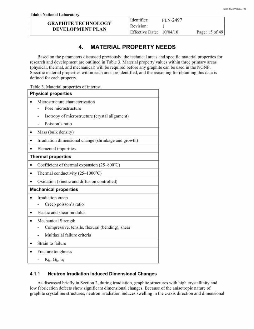
Based on the parameters discussed previously, the technical areas and specific material properties for research and development are outlined in Table 3. Material property values within three primary areas (physical, thermal, and mechanical) will be required before any graphite can be used in the NGNP. Specific material properties within each area are identified, and the reasoning for obtaining this data is defined for each property.
Table 3. Material properties of interest.
Physical properties
• Microstructure characterization
- Pore microstructure
- Isotropy of microstructure (crystal alignment)
- Poisson’s ratio
• Mass (bulk density)
• Irradiation dimensional change (shrinkage and growth)
• Elemental impurities
Thermal properties
• Coefficient of thermal expansion (25–800oC)
• Thermal conductivity (25–1000oC)
• Oxidation (kinetic and diffusion controlled)
Mechanical properties
• Irradiation creep
- Creep poisson’s ratio
• Elastic and shear modulus
• Mechanical Strength
- Compressive, tensile, flexural (bending), shear
- Multiaxial failure criteria
• Strain to failure
• Fracture toughness
- KIc, GIc, σf
4.1.1 Neutron Irradiation Induced Dimensional Changes
As discussed briefly in Section 2, during irradiation, graphite structures with high crystallinity and low fabrication defects show significant dimensional changes. Because of the anisotropic nature of graphite crystalline structures, neutron irradiation induces swelling in the c-axis direction and dimensional
Form 412.09 (Rev. 10)
Idaho National Laboratory
GRAPHITE TECHNOLOGY
DEVELOPMENT PLAN
Identifier: Revision: Effective Date:
PLN-2497 1 10/04/10 Page: 16 of 49
shrinkage in the a-axis direction. Processing defects and crystallite misalignment imposed upon the microstructure during fabrication cooldown (cracks parallel to the c-axis planes) physically accommodate the c-axis swelling, and these cracks close as the material swells perpendicular to the c-axis. This crystallite misalignment and damage within the microstructure provides a ready volume of space that can initially accommodate the crystallite swelling during irradiation. Since the c-axis swelling is accommodated, the macroscopic response is one of overall shrinkage because of a-axis shrinkage throughout the graphite volume.
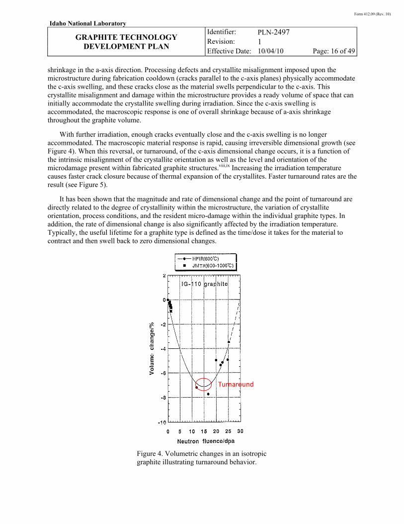
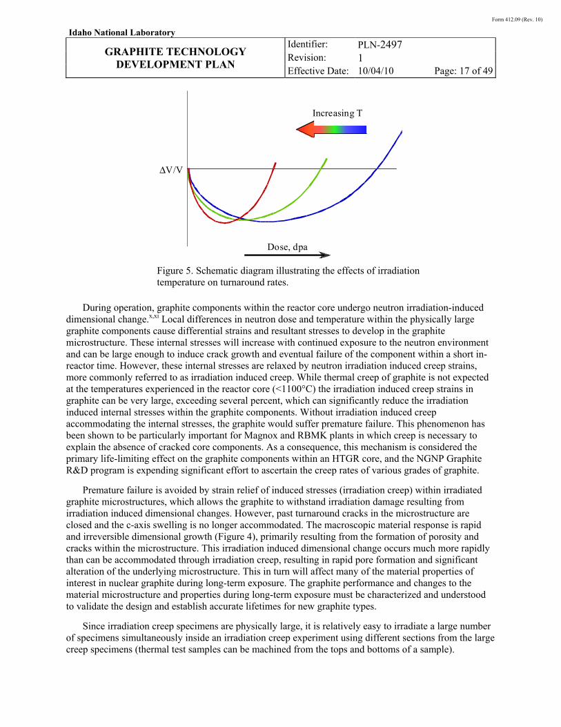
With further irradiation, enough cracks eventually close and the c-axis swelling is no longer accommodated. The macroscopic material response is rapid, causing irreversible dimensional growth (see Figure 4). When this reversal, or turnaround, of the c-axis dimensional change occurs, it is a function of the intrinsic misalignment of the crystallite orientation as well as the level and orientation of the microdamage present within fabricated graphite structures.viii,ix Increasing the irradiation temperature causes faster crack closure because of thermal expansion of the crystallites. Faster turnaround rates are the result (see Figure 5).
It has been shown that the magnitude and rate of dimensional change and the point of turnaround are directly related to the degree of crystallinity within the microstructure, the variation of crystallite orientation, process conditions, and the resident micro-damage within the individual graphite types. In addition, the rate of dimensional change is also significantly affected by the irradiation temperature. Typically, the useful lifetime for a graphite type is defined as the time/dose it takes for the material to contract and then swell back to zero dimensional changes.
Figure 4. Volumetric changes in an isotropic graphite illustrating turnaround behavior.
Turnaround
Form 412.09 (Rev. 10)
Idaho National Laboratory
GRAPHITE TECHNOLOGY
DEVELOPMENT PLAN
Identifier: Revision: Effective Date:
PLN-2497 1 10/04/10 Page: 17 of 49
Figure 5. Schematic diagram illustrating the effects of irradiation temperature on turnaround rates.
During operation, graphite components within the reactor core undergo neutron irradiation-induced dimensional change.x,xi Local differences in neutron dose and temperature within the physically large graphite components cause differential strains and resultant stresses to develop in the graphite microstructure. These internal stresses will increase with continued exposure to the neutron environment and can be large enough to induce crack growth and eventual failure of the component within a short in-reactor time. However, these internal stresses are relaxed by neutron irradiation induced creep strains, more commonly referred to as irradiation induced creep. While thermal creep of graphite is not expected at the temperatures experienced in the reactor core (<1100°C) the irradiation induced creep strains in graphite can be very large, exceeding several percent, which can significantly reduce the irradiation induced internal stresses within the graphite components. Without irradiation induced creep accommodating the internal stresses, the graphite would suffer premature failure. This phenomenon has been shown to be particularly important for Magnox and RBMK plants in which creep is necessary to explain the absence of cracked core components. As a consequence, this mechanism is considered the primary life-limiting effect on the graphite components within an HTGR core, and the NGNP Graphite R&D program is expending significant effort to ascertain the creep rates of various grades of graphite.
Premature failure is avoided by strain relief of induced stresses (irradiation creep) within irradiated graphite microstructures, which allows the graphite to withstand irradiation damage resulting from irradiation induced dimensional changes. However, past turnaround cracks in the microstructure are closed and the c-axis swelling is no longer accommodated. The macroscopic material response is rapid and irreversible dimensional growth (Figure 4), primarily resulting from the formation of porosity and cracks within the microstructure. This irradiation induced dimensional change occurs much more rapidly than can be accommodated through irradiation creep, resulting in rapid pore formation and significant alteration of the underlying microstructure. This in turn will affect many of the material properties of interest in nuclear graphite during long-term exposure. The graphite performance and changes to the material microstructure and properties during long-term exposure must be characterized and understood to validate the design and establish accurate lifetimes for new graphite types.
Since irradiation creep specimens are physically large, it is relatively easy to irradiate a large number of specimens simultaneously inside an irradiation creep experiment using different sections from the large creep specimens (thermal test samples can be machined from the tops and bottoms of a sample).
Increasing T
Dose, dpa
ΔV/V
Form 412.09 (Rev. 10)
Idaho National Laboratory
GRAPHITE TECHNOLOGY
DEVELOPMENT PLAN
Identifier: Revision: Effective Date:
PLN-2497 1 10/04/10 Page: 18 of 49
Therefore, while investigating irradiation creep rates, all other irradiated material property values can be determined using both the creep samples and piggy-back irradiation samples within an irradiation capsule.
4.1.2 Neutron Irradiation Induced Thermal Conductivity Changes
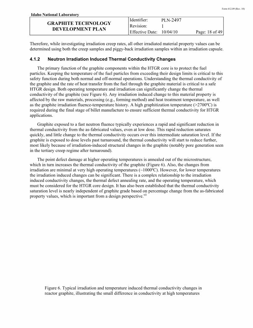
The primary function of the graphite components within the HTGR core is to protect the fuel particles. Keeping the temperature of the fuel particles from exceeding their design limits is critical to this safety function during both normal and off-normal operations. Understanding the thermal conductivity of the graphite and the rate of heat transfer from the fuel through the graphite material is critical to a safe HTGR design. Both operating temperature and irradiation can significantly change the thermal conductivity of the graphite (see Figure 6). Any irradiation induced change to this material property is affected by the raw materials, processing (e.g., forming method) and heat treatment temperature, as well as the graphite irradiation fluence-temperature history. A high graphitization temperature (>2700ºC) is required during the final stage of billet manufacture to ensure sufficient thermal conductivity for HTGR applications.
Graphite exposed to a fast neutron fluence typically experiences a rapid and significant reduction in thermal conductivity from the as-fabricated values, even at low dose. This rapid reduction saturates quickly, and little change to the thermal conductivity occurs over this intermediate saturation level. If the graphite is exposed to dose levels past turnaround, the thermal conductivity will start to reduce further, most likely because of irradiation-induced structural changes in the graphite (notably pore generation seen in the tertiary creep regime after turnaround).
The point defect damage at higher operating temperatures is annealed out of the microstructure, which in turn increases the thermal conductivity of the graphite (Figure 6). Also, the changes from irradiation are minimal at very high operating temperatures (~1000ºC). However, for lower temperatures the irradiation induced changes can be significant. There is a complex relationship to the irradiation induced conductivity changes, the thermal defect annealing rate, and the operating temperature, which must be considered for the HTGR core design. It has also been established that the thermal conductivity saturation level is nearly independent of graphite grade based on percentage change from the as-fabricated property values, which is important from a design perspective.xii
Figure 6. Typical irradiation and temperature induced thermal conductivity changes in reactor graphite, illustrating the small difference in conductivity at high temperatures
Form 412.09 (Rev. 10)
Idaho National Laboratory
GRAPHITE TECHNOLOGY
DEVELOPMENT PLAN
Identifier: Revision: Effective Date:
PLN-2497 1 10/04/10 Page: 19 of 49
4.1.3 Specific Heat Capacity Changes
In addition to the thermal conductivity the specific heat capacity, which is the energy required to increase the temperature of a unit mass of a material by unit temperature, is important for determining the thermal response of the graphite core in both normal and off-normal operation. Nuclear graphite has a relatively high specific heat capacity, allowing it to moderate temperature transients during normal operations and to store thermal energy during the initial stages of an off-normal event. This helps reduce the temperatures of the fuel and metallic components of the HTGR reactor to acceptable levels. Generally, the heat capacity for all nuclear graphite types increase with increasing temperature. It has been shown that the measured heat capacity values between the different nuclear grades and theoretically calculated specific heat capacity for graphite is very small (as an example see ASTM C781).
For irradiated graphite the specific heat varies little from the as-fabricated value at similar temperatures. This is an important factor when considering the design of the core and the response of the graphite during both normal and off-normal operations. However, at lower irradiation temperatures (RT-300°C), graphite structures have been shown to sustain and retain the damage resulting from neutron irradiation. At these (and lower temperatures) significant levels of stored energy in the form of irradiation induced Frenkel pair defects can accumulate within the microstructure. When the defects recombine the excess energy is released as heat in the graphite crystals.xiii If large amounts of irradiation induced damage recombines in the crystal structure the released energy (heat) can exceed the material’s specific heat and uncontrolled oxidation can occur if the material is exposed to air or steam at high temperatures (Wigner energy release problem). However, this issue is effectively eliminated at higher operating temperatures where increased point defect mobility promotes rapid recombination of point defects and the formation of more stable defect clusters.xiv With a reduced number of point defects in the crystal structure the energy released during recombination is significantly reduced and uncontrolled oxidation is not possible.
There are some concerns that energy stored within the graphite microstructure as a consequence of irradiation damage can be released if graphite is raised to a high temperature (the Wigner energy release phenomenon). If there is an off-normal event where the graphite is undergoing air oxidation, this additional stored energy, along with the heat generated from graphite oxidation, may exceed the specific heat value and produce a runaway reaction. While it is generally agreed that energy storage mechanisms common in low temperature operations will not be present for high temperature operations such as anticipated for the HTGR a few studies suggest that very high energy peaks may occur at the high operating temperatures of the NGNP. This high temperature energy release phenomenon must be confirmed to ensure the safe operation of the graphite during off-normal operations. As part of qualification, it will also be necessary to confirm the temperature dependence of the heat capacity of any selected grade and more importantly, confirm that this remains unchanged after irradiation at the required fluence and temperature levels.
4.1.4 Emissivity Changes
During an off-normal event the graphite must transfer the heat out of the core to the final heat sink,. This requires heat transport via thermal radiation across the gas gap between the graphite core and the steel core barrel. Thermal emissivity is defined as the ratio of energy radiated by a material to that radiated by a theoretical black body (emissivity = 1) at the same temperature. Since graphite is nearly the perfect black body material, the emissivity of a given graphite will largely depend upon the component surface condition and the operating environment. There is some question about the surface condition (and thus the emissivity) of graphite components after chronic exposure to oxidation resulting from impurities in the helium coolant. Typical emissivity values for carbon or graphite range between 0.8 and 0.9. The emissivity of nuclear graphite is not expected to change significantly with irradiation.
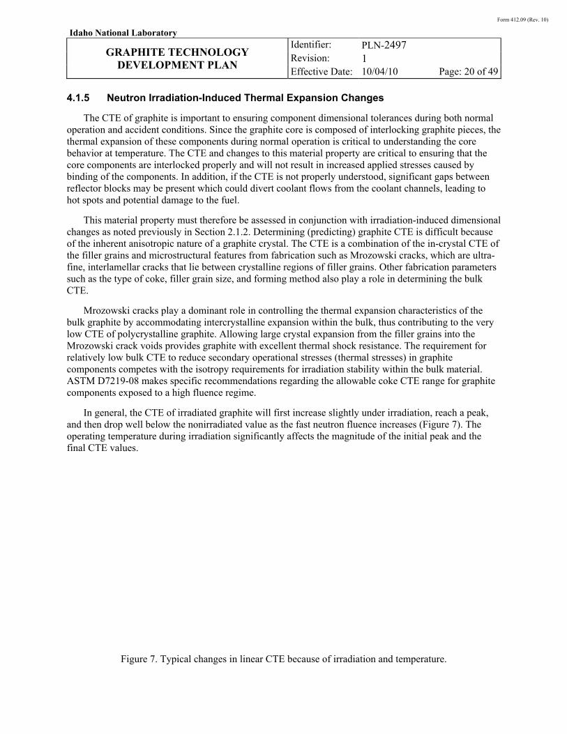
Form 412.09 (Rev. 10)
Idaho National Laboratory
GRAPHITE TECHNOLOGY
DEVELOPMENT PLAN
Identifier: Revision: Effective Date:
PLN-2497 1 10/04/10 Page: 20 of 49
4.1.5 Neutron Irradiation-Induced Thermal Expansion Changes
The CTE of graphite is important to ensuring component dimensional tolerances during both normal operation and accident conditions. Since the graphite core is composed of interlocking graphite pieces, the thermal expansion of these components during normal operation is critical to understanding the core behavior at temperature. The CTE and changes to this material property are critical to ensuring that the core components are interlocked properly and will not result in increased applied stresses caused by binding of the components. In addition, if the CTE is not properly understood, significant gaps between reflector blocks may be present which could divert coolant flows from the coolant channels, leading to hot spots and potential damage to the fuel.
This material property must therefore be assessed in conjunction with irradiation-induced dimensional changes as noted previously in Section 2.1.2. Determining (predicting) graphite CTE is difficult because of the inherent anisotropic nature of a graphite crystal. The CTE is a combination of the in-crystal CTE of the filler grains and microstructural features from fabrication such as Mrozowski cracks, which are ultra-fine, interlamellar cracks that lie between crystalline regions of filler grains. Other fabrication parameters such as the type of coke, filler grain size, and forming method also play a role in determining the bulk CTE.
Mrozowski cracks play a dominant role in controlling the thermal expansion characteristics of the bulk graphite by accommodating intercrystalline expansion within the bulk, thus contributing to the very low CTE of polycrystalline graphite. Allowing large crystal expansion from the filler grains into the Mrozowski crack voids provides graphite with excellent thermal shock resistance. The requirement for relatively low bulk CTE to reduce secondary operational stresses (thermal stresses) in graphite components competes with the isotropy requirements for irradiation stability within the bulk material. ASTM D7219-08 makes specific recommendations regarding the allowable coke CTE range for graphite components exposed to a high fluence regime.
In general, the CTE of irradiated graphite will first increase slightly under irradiation, reach a peak, and then drop well below the nonirradiated value as the fast neutron fluence increases (Figure 7). The operating temperature during irradiation significantly affects the magnitude of the initial peak and the final CTE values.
Figure 7. Typical changes in linear CTE because of irradiation and temperature.
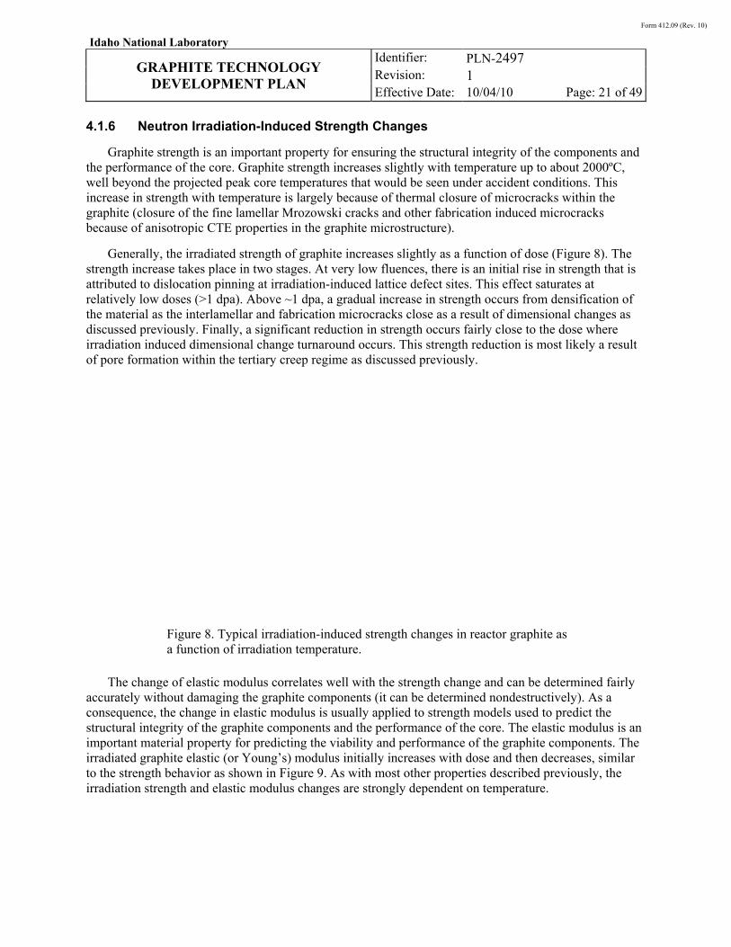
Form 412.09 (Rev. 10)
Idaho National Laboratory
GRAPHITE TECHNOLOGY
DEVELOPMENT PLAN
Identifier: Revision: Effective Date:
PLN-2497 1 10/04/10 Page: 21 of 49
4.1.6 Neutron Irradiation-Induced Strength Changes
Graphite strength is an important property for ensuring the structural integrity of the components and the performance of the core. Graphite strength increases slightly with temperature up to about 2000ºC, well beyond the projected peak core temperatures that would be seen under accident conditions. This increase in strength with temperature is largely because of thermal closure of microcracks within the graphite (closure of the fine lamellar Mrozowski cracks and other fabrication induced microcracks because of anisotropic CTE properties in the graphite microstructure).
Generally, the irradiated strength of graphite increases slightly as a function of dose (Figure 8). The strength increase takes place in two stages. At very low fluences, there is an initial rise in strength that is attributed to dislocation pinning at irradiation-induced lattice defect sites. This effect saturates at relatively low doses (>1 dpa). Above ~1 dpa, a gradual increase in strength occurs from densification of the material as the interlamellar and fabrication microcracks close as a result of dimensional changes as discussed previously. Finally, a significant reduction in strength occurs fairly close to the dose where irradiation induced dimensional change turnaround occurs. This strength reduction is most likely a result of pore formation within the tertiary creep regime as discussed previously.
Figure 8. Typical irradiation-induced strength changes in reactor graphite as a function of irradiation temperature.
The change of elastic modulus correlates well with the strength change and can be determined fairly accurately without damaging the graphite components (it can be determined nondestructively). As a consequence, the change in elastic modulus is usually applied to strength models used to predict the structural integrity of the graphite components and the performance of the core. The elastic modulus is an important material property for predicting the viability and performance of the graphite components. The irradiated graphite elastic (or Young’s) modulus initially increases with dose and then decreases, similar to the strength behavior as shown in Figure 9. As with most other properties described previously, the irradiation strength and elastic modulus changes are strongly dependent on temperature.
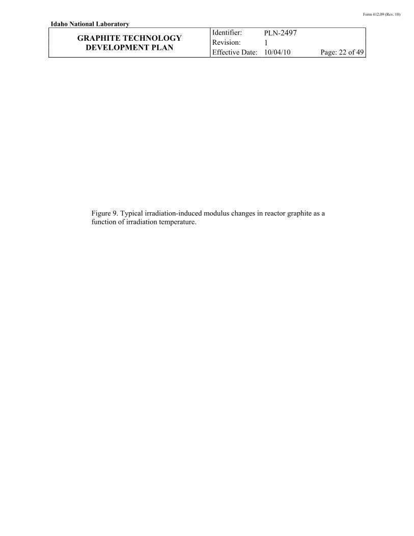
Form 412.09 (Rev. 10)
Idaho National Laboratory
GRAPHITE TECHNOLOGY
DEVELOPMENT PLAN
Identifier: Revision: Effective Date:
PLN-2497 1 10/04/10 Page: 22 of 49
Figure 9. Typical irradiation-induced modulus changes in reactor graphite as a function of irradiation temperature.
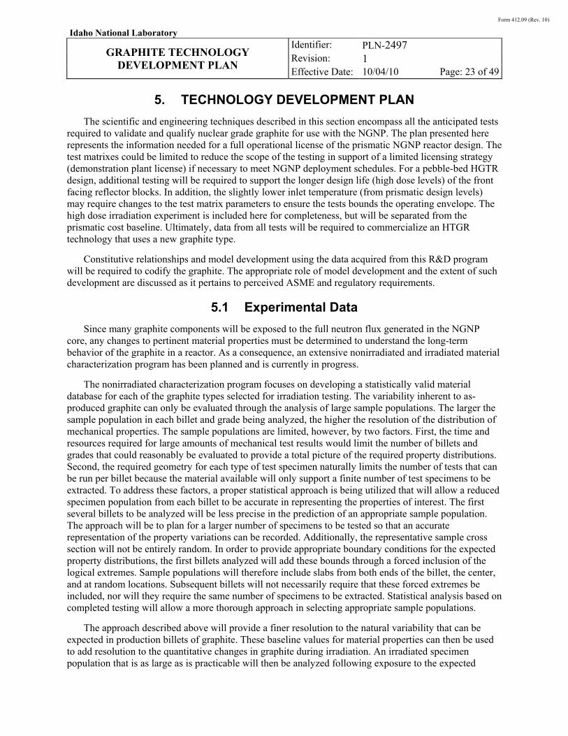
Form 412.09 (Rev. 10)
Idaho National Laboratory
GRAPHITE TECHNOLOGY
DEVELOPMENT PLAN
Identifier: Revision: Effective Date:
PLN-2497 1 10/04/10 Page: 23 of 49
5. TECHNOLOGY DEVELOPMENT PLAN
The scientific and engineering techniques described in this section encompass all the anticipated tests required to validate and qualify nuclear grade graphite for use with the NGNP. The plan presented here represents the information needed for a full operational license of the prismatic NGNP reactor design. The test matrixes could be limited to reduce the scope of the testing in support of a limited licensing strategy (demonstration plant license) if necessary to meet NGNP deployment schedules. For a pebble-bed HGTR design, additional testing will be required to support the longer design life (high dose levels) of the front facing reflector blocks. In addition, the slightly lower inlet temperature (from prismatic design levels) may require changes to the test matrix parameters to ensure the tests bounds the operating envelope. The high dose irradiation experiment is included here for completeness, but will be separated from the prismatic cost baseline. Ultimately, data from all tests will be required to commercialize an HTGR technology that uses a new graphite type.
Constitutive relationships and model development using the data acquired from this R&D program will be required to codify the graphite. The appropriate role of model development and the extent of such development are discussed as it pertains to perceived ASME and regulatory requirements.
5.1 Experimental Data
Since many graphite components will be exposed to the full neutron flux generated in the NGNP core, any changes to pertinent material properties must be determined to understand the long-term behavior of the graphite in a reactor. As a consequence, an extensive nonirradiated and irradiated material characterization program has been planned and is currently in progress.
The nonirradiated characterization program focuses on developing a statistically valid material database for each of the graphite types selected for irradiation testing. The variability inherent to as-produced graphite can only be evaluated through the analysis of large sample populations. The larger the sample population in each billet and grade being analyzed, the higher the resolution of the distribution of mechanical properties. The sample populations are limited, however, by two factors. First, the time and resources required for large amounts of mechanical test results would limit the number of billets and grades that could reasonably be evaluated to provide a total picture of the required property distributions. Second, the required geometry for each type of test specimen naturally limits the number of tests that can be run per billet because the material available will only support a finite number of test specimens to be extracted. To address these factors, a proper statistical approach is being utilized that will allow a reduced specimen population from each billet to be accurate in representing the properties of interest. The first several billets to be analyzed will be less precise in the prediction of an appropriate sample population. The approach will be to plan for a larger number of specimens to be tested so that an accurate representation of the property variations can be recorded. Additionally, the representative sample cross section will not be entirely random. In order to provide appropriate boundary conditions for the expected property distributions, the first billets analyzed will add these bounds through a forced inclusion of the logical extremes. Sample populations will therefore include slabs from both ends of the billet, the center, and at random locations. Subsequent billets will not necessarily require that these forced extremes be included, nor will they require the same number of specimens to be extracted. Statistical analysis based on completed testing will allow a more thorough approach in selecting appropriate sample populations.
The approach described above will provide a finer resolution to the natural variability that can be expected in production billets of graphite. These baseline values for material properties can then be used to add resolution to the quantitative changes in graphite during irradiation. An irradiated specimen population that is as large as is practicable will then be analyzed following exposure to the expected
Form 412.09 (Rev. 10)
Idaho National Laboratory
GRAPHITE TECHNOLOGY
DEVELOPMENT PLAN
Identifier: Revision: Effective Date:
PLN-2497 1 10/04/10 Page: 24 of 49
NGNP reactor environment (temperature and dose ranges). As stated previously, this experiment is expected to yield pertinent information for all irradiated material property values necessary to qualify a new nuclear grade graphite. However, doses and temperatures experienced within the PMR design are expected to be different than the pebble-bed design. Generally, the PMR design operates at slightly higher temperatures while the PBR design operates for longer periods of time (see Section 3.1.2).
Specific descriptions of test sample preparation, nonirradiated material characterization, irradiation experiment descriptions, and material characterization comprising the experimental data needs are presented below.
5.1.1 Test Sample Preparation
Before any material characterization testing (nonirradiated or irradiated) can be carried out, an optimal method of machining the graphite samples from the bulk material must be developed to ensure representative samples can be obtained. The NGNP Project has developed an extensive sample cutting and sectioning plan to guarantee not only statistically valid sample numbers but also spacial validity so that microstructural changes within the bulk material (billets) affecting material property changes are well characterized.xv,xvi,xvii Particular attention has been given to the traceability of each specimen to its spatial location and orientation within a billet.
These graphite billet cutting plans were developed to promote a more complete or finer resolution mapping of material property changes within the billets. This was achieved by maximizing the number of test specimens that could be obtained from each billet. To facilitate machining, the billets are cut into successively smaller sections, designated as slabs, and each slab is sized to accommodate the proper grain orientation within the test specimens. All test specimen blanks machined for a given slab will have the same grain orientation (against grain or with grain) as the slab. The slabs will be further sectioned into subslabs to allow the rectangular test specimen blanks to be machined to the correct size (Figure 10). A tracking methodology is then used that will account for every specimen machined from a graphite billet. A unique identification number will be assigned to each test specimen providing the exact location and orientation of the sample within the graphite billet. This identification system is based on the cutting methodology to provide an easy and concise method for identifying the different samples. This methodology (and the corresponding assumptions) will be used for producing all test specimens for material characterization.
Figure 10. Example typical graphite billet sectioning plan.
Form 412.09 (Rev. 10)
Idaho National Laboratory
GRAPHITE TECHNOLOGY
DEVELOPMENT PLAN
Identifier: Revision: Effective Date:
PLN-2497 1 10/04/10 Page: 25 of 49
Since a large portion of the testing is with irradiated samples, a minimum specimen size must also be considered for volume restrictions within a materials test reactor (MTR). Each material test will depend on the specific graphite’s grain size, since ASTM test standards call for specimen sizes to have cross-sectional diameters of at least five-times the grain size across the stressed gauge section of the sample. This sizing requirement helps ensure representative and repeatable testing results. However, most graphite material tests use a minimum of ten-times the maximum grain size for the cross-sectional diameter across the gauge section. Thus, for graphite with a 1 mm grain size, the minimum diameter in the test gauge area for a typical tensile specimen must be ~10 mm. Fabricating smaller test specimens is not allowed because they will not provide representative material properties across such a few number of grains in the material microstructure. Other graphite types with smaller grain sizes may use smaller gauge sections, again, depending on the material’s grain size.
5.1.2 Nonirradiated Material Testing
As-received material baseline properties for each graphite type are needed to establish accurate thermal and mechanical core responses. Since material properties are expected to vary throughout the rather large billets or blocks of graphite, mapping of the magnitude and spacial positions of variability is important in determining an individual component’s material properties. To enable credible core designs and to support the ongoing development of a probabilistic graphite design methodology, the maximum variability within graphite components must be well characterized. For example, if the compressive strength is reduced significantly near the edges of the billets, a graphite support column fabricated from a position near the edge may not possess sufficient strength to support the weight of the core blocks above. Thus, determining where the strength begins to be reduced within the larger billet and by how much is important for determining where to fabricate an individual graphite component to meet specific design requirements within the core.
A complicating factor is the variability within the individual billets, from billet-to-billet and from batch-to-batch. These within-intrabillet, interbillet, and batch-to-batch variations of the graphite must be accounted for in a statistical manner to determine the maximum range of material property variations expected for components machined from an average billet. Such a statistical material property database can only be obtained from an extensive nonirradiation characterization of samples taken within billets and compared with samples between different billets and different graphite batches.
Physical, thermal, and mechanical property testing of multiple graphite samples from a large billet sample matrix is therefore necessary to determine the proper statistical ranges of values. The appropriate sample matrix size, sample geometry, and sample dimensions, as described above, will be important to establishing statistical validity. All material tests to be used to build this material property database are described later in this section. Once the nonirradiated as-received material properties have been determined, the changes caused by irradiation will be determined from post-irradiation examination (PIE) and characterization studies of representative graphite types.
5.1.3 Irradiation Experiments
Since the graphite will be exposed to a high energy neutron environment, a series of irradiation experiments will be required to determine the graphite response under irradiation. The irradiation conditions are determined based upon the expected reactor conditions as described in Section 3 and a programmatic requirement to provide data useful to both PMR and PBR designs. PIE and characterization entails performing the same physical, thermal, and mechanical tests as described for nonirradiated materials, only this time with irradiated graphite samples.
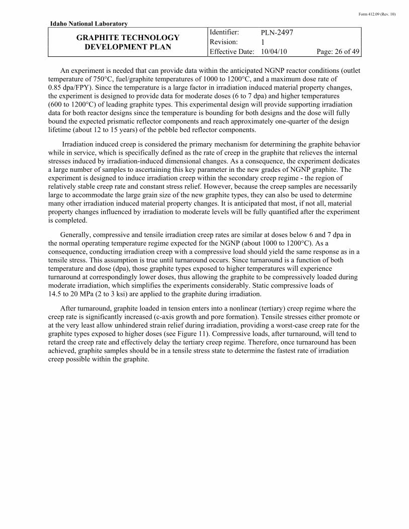
Form 412.09 (Rev. 10)
Idaho National Laboratory
GRAPHITE TECHNOLOGY
DEVELOPMENT PLAN
Identifier: Revision: Effective Date:
PLN-2497 1 10/04/10 Page: 26 of 49
An experiment is needed that can provide data within the anticipated NGNP reactor conditions (outlet temperature of 750°C, fuel/graphite temperatures of 1000 to 1200°C, and a maximum dose rate of 0.85 dpa/FPY). Since the temperature is a large factor in irradiation induced material property changes, the experiment is designed to provide data for moderate doses (6 to 7 dpa) and higher temperatures (600 to 1200°C) of leading graphite types. This experimental design will provide supporting irradiation data for both reactor designs since the temperature is bounding for both designs and the dose will fully bound the expected prismatic reflector components and reach approximately one-quarter of the design lifetime (about 12 to 15 years) of the pebble bed reflector components.
Irradiation induced creep is considered the primary mechanism for determining the graphite behavior while in service, which is specifically defined as the rate of creep in the graphite that relieves the internal stresses induced by irradiation-induced dimensional changes. As a consequence, the experiment dedicates a large number of samples to ascertaining this key parameter in the new grades of NGNP graphite. The experiment is designed to induce irradiation creep within the secondary creep regime - the region of relatively stable creep rate and constant stress relief. However, because the creep samples are necessarily large to accommodate the large grain size of the new graphite types, they can also be used to determine many other irradiation induced material property changes. It is anticipated that most, if not all, material property changes influenced by irradiation to moderate levels will be fully quantified after the experiment is completed.
Generally, compressive and tensile irradiation creep rates are similar at doses below 6 and 7 dpa in the normal operating temperature regime expected for the NGNP (about 1000 to 1200°C). As a consequence, conducting irradiation creep with a compressive load should yield the same response as in a tensile stress. This assumption is true until turnaround occurs. Since turnaround is a function of both temperature and dose (dpa), those graphite types exposed to higher temperatures will experience turnaround at correspondingly lower doses, thus allowing the graphite to be compressively loaded during moderate irradiation, which simplifies the experiments considerably. Static compressive loads of 14.5 to 20 MPa (2 to 3 ksi) are applied to the graphite during irradiation.
After turnaround, graphite loaded in tension enters into a nonlinear (tertiary) creep regime where the creep rate is significantly increased (c-axis growth and pore formation). Tensile stresses either promote or at the very least allow unhindered strain relief during irradiation, providing a worst-case creep rate for the graphite types exposed to higher doses (see Figure 11). Compressive loads, after turnaround, will tend to retard the creep rate and effectively delay the tertiary creep regime. Therefore, once turnaround has been achieved, graphite samples should be in a tensile stress state to determine the fastest rate of irradiation creep possible within the graphite.
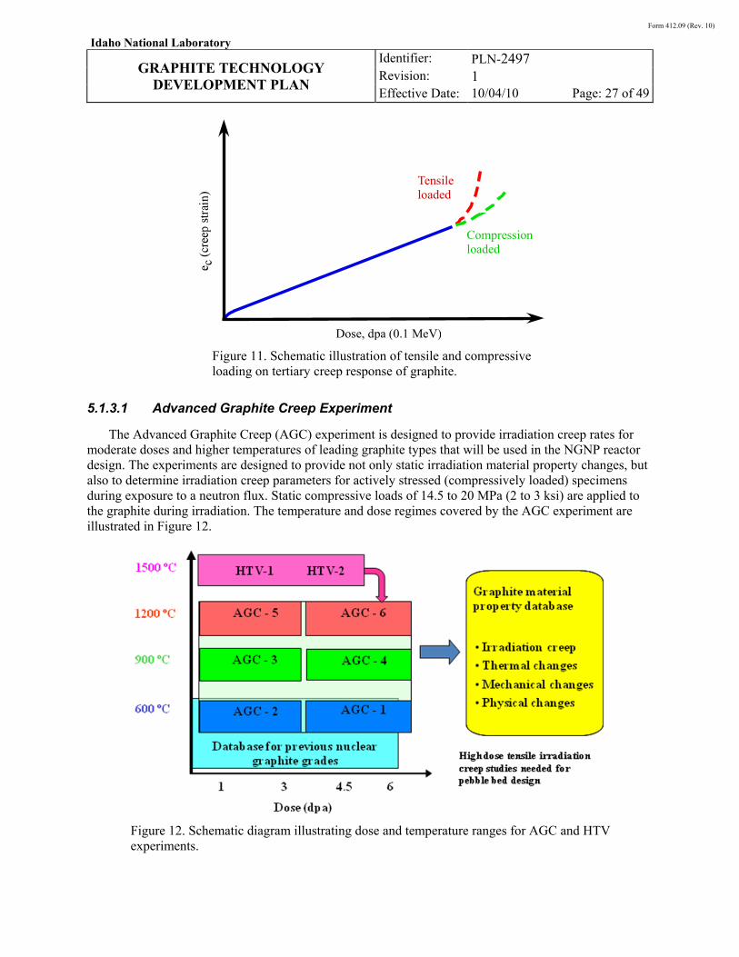
Form 412.09 (Rev. 10)
Idaho National Laboratory
GRAPHITE TECHNOLOGY
DEVELOPMENT PLAN
Identifier: Revision: Effective Date:
PLN-2497 1 10/04/10 Page: 27 of 49
Figure 11. Schematic illustration of tensile and compressive loading on tertiary creep response of graphite.
5.1.3.1 Advanced Graphite Creep Experiment
The Advanced Graphite Creep (AGC) experiment is designed to provide irradiation creep rates for moderate doses and higher temperatures of leading graphite types that will be used in the NGNP reactor design. The experiments are designed to provide not only static irradiation material property changes, but also to determine irradiation creep parameters for actively stressed (compressively loaded) specimens during exposure to a neutron flux. Static compressive loads of 14.5 to 20 MPa (2 to 3 ksi) are applied to the graphite during irradiation. The temperature and dose regimes covered by the AGC experiment are illustrated in Figure 12.
Figure 12. Schematic diagram illustrating dose and temperature ranges for AGC and HTV experiments.
Dose, dpa (0.1 MeV)
Tensileloaded
Compressionloaded
Form 412.09 (Rev. 10)
Idaho National Laboratory
GRAPHITE TECHNOLOGY
DEVELOPMENT PLAN
Identifier: Revision: Effective Date:
PLN-2497 1 10/04/10 Page: 28 of 49
As discussed, the dose is intentionally below (or possibly at) the point of turnaround within the graphite at the normal NGNP operating temperatures. Only the AGC-6 experiment (6 to 7 dpa at 1200°C) will approach expected turnaround limits for current NGNP graphite types. Since the AGC experiments are a comparison measurement between stressed and unstressed irradiated specimens, if turnaround were to occur during AGC-6 exposure, the creep rate results would be affected by the compressive loading state of the graphite. To ascertain when turnaround will occur in the current NGNP graphite types, a second experiment to measure the dimensional change rate at higher temperatures and moderate dose must be performed.
The high temperature vessel (HTV) experiment is a simple drop-in capsule experiment meant to determine the dose level at which the current NGNP graphite types will achieve turnaround. The experiment will be operated at 1500°C (inducing faster turnaround) and will be exposed to a gradient of dose levels. Turnaround point can be determined by measuring the rate of dimensional change (shrinkage) of the graphite types. This is a simple dimensional change experiment to determine when turnaround may occur, the graphite is not loaded during irradiation. A detailed description of the HTV-1 and HTV-2 experiment is presented in ORNL-GEN4/LTR-06-019.xviii
Results from the HTV experiment will provide both turnaround and high temperature irradiation data for all selected graphite types. Turnaround data from these experiments will be used to adjust the exposure, loading, and temperature limits for AGC-6 to extrapolate as much accurate information from it as possible (see Figure 12).
Since the prismatic NGNP design estimates that reflector blocks can be replaced well before turnaround should occur at normal operating temperature (<5 to 6 dpa) and fuel blocks are replaced after only two cycles (<4 to 5 dpa), the AGC experiment should fully bound the graphite experience within a prismatic design. The dpa levels achieved in the AGC experiment will not, however, fully bound the pebble-bed NGNP design for high-dose reflector blocks (see below). But, it will certainly provide preliminary data for the first 20 to 25% of the expected dpa levels for these graphite components.
Graphite components located farther from the core region will have correspondingly less dose and operate at much lower temperatures than the fuel region. As a consequence, turnaround and irradiation creep levels for these peripheral graphite components will be at significantly longer times and lower rates and should be fully bounded by the AGC data.
The first two of six capsules comprising the AGC experiment (AGC-1 and 2) will be irradiated in the south flux trap of the Advanced Test Reactor (ATR). After the second capsule (AGC-2) has been irradiated, the remaining four capsules will be irradiated within the east flux trap. This change is because of space within the ATR and other program considerations such as accelerating the NGNP fuel irradiation experiments. The irradiation campaigns are to be conducted sequentially for each capsule in the flux trap. Each capsule will contain approximately 400 specimens: 90 large irradiation creep specimen pairs and over 300 piggy-back specimens. The smaller and nonstressed piggy back specimens are located in the center channel in the experiment. Other piggy backs are used in the lower nonstressed creep specimen channels as offset specimens to account for the slight asymmetry in the ATR flux profile. The larger irradiation creep specimens are subdivided into six columns of 15 specimens each. Each of the six columns contains stressed and nonstressed specimens. The symmetry of the flux buckling within the ATR is used to irradiate each stressed and nonstressed specimens at the same fluence level. There are approximately 45 nonstressed specimens below core centerline and 45 stressed specimens above core centerline to provide the comparison for ascertaining the creep rate. The creep measurement is made on the dimensional difference between the stressed and nonstressed specimens irradiated at the same fluence and temperature. Figure 13 shows the arrangement of the graphite specimens in the experiment.
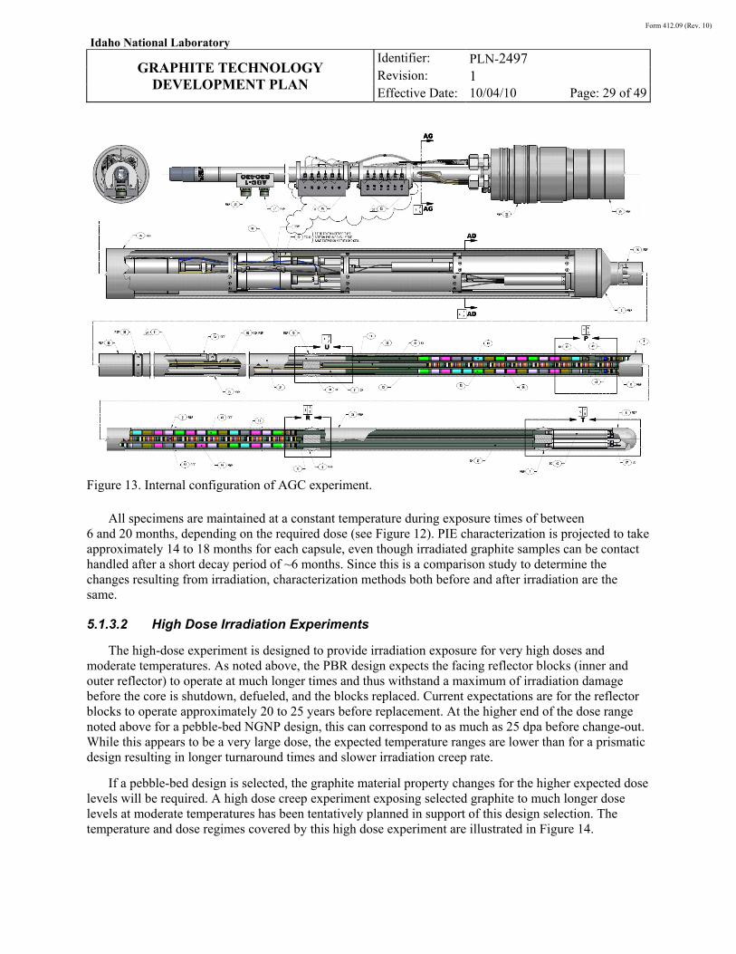
Form 412.09 (Rev. 10)
Idaho National Laboratory
GRAPHITE TECHNOLOGY
DEVELOPMENT PLAN
Identifier: Revision: Effective Date:
PLN-2497 1 10/04/10 Page: 29 of 49
Figure 13. Internal configuration of AGC experiment.
All specimens are maintained at a constant temperature during exposure times of between 6 and 20 months, depending on the required dose (see Figure 12). PIE characterization is projected to take approximately 14 to 18 months for each capsule, even though irradiated graphite samples can be contact handled after a short decay period of ~6 months. Since this is a comparison study to determine the changes resulting from irradiation, characterization methods both before and after irradiation are the same.
5.1.3.2 High Dose Irradiation Experiments
The high-dose experiment is designed to provide irradiation exposure for very high doses and moderate temperatures. As noted above, the PBR design expects the facing reflector blocks (inner and outer reflector) to operate at much longer times and thus withstand a maximum of irradiation damage before the core is shutdown, defueled, and the blocks replaced. Current expectations are for the reflector blocks to operate approximately 20 to 25 years before replacement. At the higher end of the dose range noted above for a pebble-bed NGNP design, this can correspond to as much as 25 dpa before change-out. While this appears to be a very large dose, the expected temperature ranges are lower than for a prismatic design resulting in longer turnaround times and slower irradiation creep rate.
If a pebble-bed design is selected, the graphite material property changes for the higher expected dose levels will be required. A high dose creep experiment exposing selected graphite to much longer dose levels at moderate temperatures has been tentatively planned in support of this design selection. The temperature and dose regimes covered by this high dose experiment are illustrated in Figure 14.
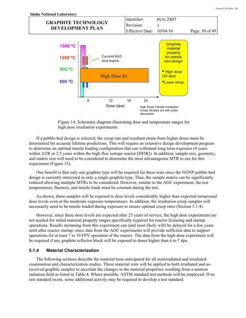
Form 412.09 (Rev. 10)
Idaho National Laboratory
GRAPHITE TECHNOLOGY
DEVELOPMENT PLAN
Identifier: Revision: Effective Date:
PLN-2497 1 10/04/10 Page: 30 of 49
Figure 14. Schematic diagram illustrating dose and temperature ranges for high dose irradiation experiments.
If a pebble-bed design is selected, the creep rate and resultant strain from higher doses must be determined for accurate lifetime predictions. This will require an extensive design development program to determine an optimal tensile loading configuration that can withstand long-term exposure (4 years within ATR or 2.5 years within the high-flux isotope reactor [HFIR]). In addition, sample size, geometry, and matrix size will need to be considered to determine the most advantageous MTR to use for this experiment (Figure 15).
One benefit is that only one graphite type will be required for these tests since the NGNP pebble-bed design is currently interested in only a single graphite type. Thus, the sample matrix can be significantly reduced allowing multiple MTRs to be considered. However, similar to the AGC experiment, the test temperatures, fluences, and tensile loads must be constant during the test.
As shown, these samples will be exposed to dose levels considerably higher than expected turnaround dose levels even at the moderate exposure temperatures. In addition, the irradiation creep samples will necessarily need to be tensile loaded during exposure to ensure optimal creep rates (Section 5.1.4).
However, since these dose levels are expected after 25 years of service, the high dose experiments are not needed for initial material property ranges specifically required for reactor licensing and startup operations. Results stemming from this experiment can (and most likely will) be delayed for a few years until after reactor startup, since data from the AGC experiments will provide sufficient data to support operations for at least 7 to 10 FPY operation of the reactor. The data from the high-dose experiment will be required if any graphite reflector block will be exposed to doses higher than 6 to 7 dpa.
5.1.4 Material Characterization
The following sections describe the material tests anticipated for all nonirradiated and irradiated examination and characterization studies. These material tests will be applied to both irradiated and as-received graphite samples to ascertain the changes to the material properties resulting from a neutron radiation field as listed in Table 4. Where possible, ASTM standard test methods will be employed. If no test standard exists, some additional activity may be required to develop a test standard.
Current AGC test matrix
900 ºC
1200 ºC
600 ºC
Graphite material property
for pebble bed design
• High dose (25 dpa)
•Lower temp.
1500 ºC
Dose (dpa)
6 12 18 24
High Dose Tensile Irradiation Creep Studies are still under discussion
High Dose Irr.
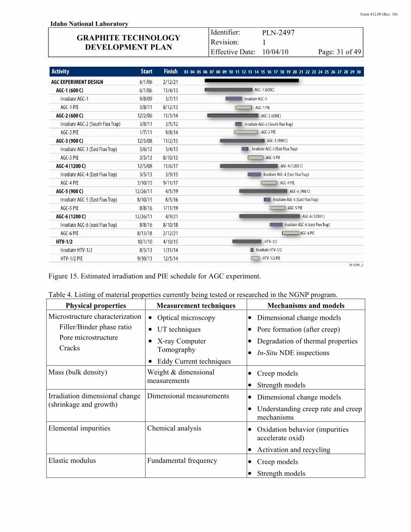
Form 412.09 (Rev. 10)
Idaho National Laboratory
GRAPHITE TECHNOLOGY
DEVELOPMENT PLAN
Identifier: Revision: Effective Date:
PLN-2497 1 10/04/10 Page: 31 of 49
Figure 15. Estimated irradiation and PIE schedule for AGC experiment.
Table 4. Listing of material properties currently being tested or researched in the NGNP program.
Physical properties Measurement techniques Mechanisms and models
Microstructure characterization
Filler/Binder phase ratio
Pore microstructure
Cracks
• Optical microscopy
• UT techniques
• X-ray Computer Tomography
• Eddy Current techniques
• Dimensional change models
• Pore formation (after creep)
• Degradation of thermal properties
• In-Situ NDE inspections
Mass (bulk density) Weight & dimensional measurements
• Creep models
• Strength models
Irradiation dimensional change (shrinkage and growth)
Dimensional measurements • Dimensional change models
• Understanding creep rate and creep mechanisms
Elemental impurities Chemical analysis • Oxidation behavior (impurities accelerate oxid)
• Activation and recycling
Elastic modulus Fundamental frequency • Creep models
• Strength models
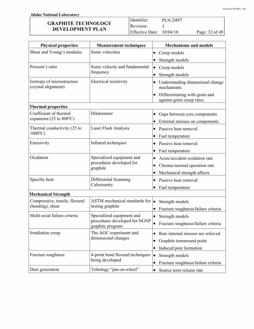
Form 412.09 (Rev. 10)
Idaho National Laboratory
GRAPHITE TECHNOLOGY
DEVELOPMENT PLAN
Identifier: Revision: Effective Date:
PLN-2497 1 10/04/10 Page: 32 of 49
Physical properties Measurement techniques Mechanisms and models
Shear and Young’s modulus Sonic velocities • Creep models
• Strength models
Poisson’s ratio Sonic velocity and fundamental frequency
• Creep models
• Strength models
Isotropy of microstructure (crystal alignment)
Electrical resistivity • Understanding dimensional change mechanisms
• Differentiating with-grain and against-grain creep rates
Thermal properties
Coefficient of thermal expansion (25 to 800ºC)
Dilatometer • Gaps between core components
• External stresses on components
Thermal conductivity (25 to 1000ºC)
Laser Flash Analysis • Passive heat removal
• Fuel temperature
Emissivity Infrared techniques • Passive heat removal
• Fuel temperature
Oxidation Specialized equipment and procedures developed for graphite
• Acute/accident oxidation rate
• Chronic/normal operation rate
• Mechanical strength affects
Specific heat Differential Scanning Calorimetry
• Passive heat removal
• Fuel temperature
Mechanical Strength
Compressive, tensile, flexural (bending), shear
ASTM mechanical standards for testing graphite
• Strength models
• Fracture toughness/failure criteria
Multi-axial failure criteria Specialized equipment and procedures developed for NGNP graphite program
• Strength models
• Fracture toughness/failure criteria
Irradiation creep The AGC experiment and dimensional changes
• Rate internal stresses are relieved
• Graphite turnaround point
• Induced pore formation
Fracture toughness 4-point bend flexural techniques being developed
• Strength models
• Fracture toughness/failure criteria
Dust generation Tribology “pin-on-wheel” • Source term release rate
Form 412.09 (Rev. 10)
Idaho National Laboratory
GRAPHITE TECHNOLOGY
DEVELOPMENT PLAN
Identifier: Revision: Effective Date:
PLN-2497 1 10/04/10 Page: 33 of 49
5.1.4.1 Physical Testing
Microstructural Characterization
Determination of grain size, morphology/anisotropy, and pore size/distribution within the graphite microstructure is critical to determining the macroscopic physical, thermal, and mechanical properties. These parameters must be determined before the graphite performance can be accurately analyzed. Optical microscopy measurements of adjacent samples will necessarily be taken as close to test specimens (with similar orientation) as possible from within the graphite billet, and the microstructure will be inferred to the test sample microstructures.
In conjunction with optical microscopy, nondestructive X-ray tomography (CT) will be investigated for its ability to ascertain the microstructure within individual test samples. X-ray techniques will allow samples to be analyzed before being tested using additional techniques (both nondestructive and destructive). Image analysis techniques will be used to enhance information such as internal pore sizes and pore structure throughout the microstructure.
Changes to the microstructure because of thermal, irradiation, and stress history will be compared to the original microstructure. Microstructural evolution and modifications as a result of exposure to reactor environments can then be established. These changes, and the responsible physical mechanisms, need to be understood so that analytical models can be developed to thoroughly understand the issues and accurately predict the response of the current and future grades of graphite in nuclear applications.
Finally, a key technological deficiency currently being addressed is the inability to determine microstructural features within a graphite material, specifically with nondestructive techniques. This is important for determining not only the evolution in test specimen microstructures as a function of irradiation, but also for determining defects within the large graphite billets. Nondestructive methods for large scale analysis (i.e., manufacturing, ISI methods, etc.) are being developed. CT methods may be possible but have limited resolutions for these large component sizes. Ultrasonic testing (UT), electrical resistivity/conductivity, impact echo, or other techniques are currently being investigated for development to meet both ISI requirements and billet characterization for manufacturing QA. Inspecting billets without damage to ensure proper microstructural development is one of the largest problems facing any QA program for purchasing of nuclear grade graphite. The implementation of nondestructive techniques will be necessary for accurate QA.
Irradiation Dimensional Change
Dimensional change during reactor service is one of the key parameters defining a nuclear grade graphite. Determination of volumetric and density changes as a function of temperature and dose will be necessary to understand critical performance measures, such as turnaround, irradiation creep, and internal stresses imposed upon graphite components. Precision measurements of all irradiation test samples will allow macroscopic dimensional changes and pore formation estimates to be determined.
This key material behavior will be ascertained in the AGC experiments. Exacting dimensional measurements of the samples both before and after irradiation will be conducted to determine the changes in the sample volume. The mass of each sample both before and after irradiation will be performed to determine any changes. Volumetric and density changes will be calculated and compared to preirradiation values for each test sample. Using this data, the AGC experiment will provide the irradiation induced dimensional changes as a function of temperature and dose.
Form 412.09 (Rev. 10)
Idaho National Laboratory
GRAPHITE TECHNOLOGY
DEVELOPMENT PLAN
Identifier: Revision: Effective Date:
PLN-2497 1 10/04/10 Page: 34 of 49
Isotropy of Microstructure
Electrical conductivity is used as a rapid, simple means to determine grain orientation, structure, and crystallinity of the graphite. In conjunction with optical microscopy, it can be used to determine the microstructural texture of the graphite components without a great deal of sample preparation work.
Electrical conductivity/resistivity values will be measured through sample button resistivity measurements. Microstructural characteristics will be compared to optical and CT results. These tests will be performed as possible based on the material geometry and size.
Chemical Impurities
All major grades of graphite will need to meet the maximum impurity levels specified in ASTM 7219. This requirement is not necessary or desirable for the minor grades of graphite which are experimental in nature. All graphite types will be chemically analyzed to determine the level of trace impurities in each graphite type.
The chemical impurity levels are determined at the billet level with small samples taken from each billet with the assumptions that the chemical impurity levels within these samples are representative throughout the entire billet.
Elastic and Shear Modulus
The elastic and shear modulus are critical material property values used in analytical models predicting the strength, irradiation creep, and dimensional change. As a consequence, a number of different nondestructive techniques are employed to determine these material properties along with the corresponding Poisson’s ratio. Ultrasonic, resonance frequency, and combinations of these techniques are used to determine this key material property. Nondestructive techniques are employed to allow before and after irradiation measurements.
5.1.4.2 Thermal Testing
All thermal (and electrical) samples will be button samples having dimensions equal to or less than 12 mm diameter by 6 mm thickness. These small sample sizes allow for many specimens to be made available for both irradiated and nonirradiated testing. The small size also allows thermal samples to be machined from the ends of mechanical test specimens, if needed, thereby ensuring spacial uniformity of measurements of relevant thermal, physical, and mechanical material properties within the graphite billet characterization. Additionally, reusing the same samples allows for larger sample batches within the irradiation test trains.
Thermal Expansion & Conductivity
Thermal expansion and conductivity values will be obtained from graphite button samples within a laser flash diffusivity analyzer up to temperatures of 1600°C (off-normal maximum temperature). Nonirradiated and irradiated button samples will be prepared for testing at all temperature ranges of interest.
Oxidation
Recently (in 2009) a new ASTM test standard was developed and approved for oxidation testing of graphite. This standard addresses the kinetic controlled oxidation regime and provides a good test method
Form 412.09 (Rev. 10)
Idaho National Laboratory
GRAPHITE TECHNOLOGY
DEVELOPMENT PLAN
Identifier: Revision: Effective Date:
PLN-2497 1 10/04/10 Page: 35 of 49
to determine the rate of oxidation of the graphite components during off-normal, air-ingress events. This standard is being used to verify and validate kinetic models that are used to predict weight loss in specific areas of the core during off-normal events.
However, in addition to this kinetic-based test standard, a comprehensive model predicting both kinetic and diffusion controlled oxidation is required. To address this need specific areas of research are required in the (1) inclusion of both oxidation kinetics and diffusion behavior of oxidizing species within the graphite structure, (2) development of active predictive capability to account for coolant impurities and associated time- and special-dependent strength loss, and (3) code applicable not only to normal operation and transient conditions, but also to acute (accident) scenarios.vii Such code is needed to evaluate the service lifetime and the need for replacement of graphite structural components.
Activities for predicting the long-term, chronic (diffusion controlled) oxidation rate of graphite are ongoing. A systematic effort is being pursued to characterize fundamental material properties that determine oxidation behavior (chemical reactivity and diffusion transport) of candidate NGNP graphite materials. This activity considers each of the possible oxidant species (O2, CO2, H2O) that will be present in the coolant helium and covers normal operation, transient, and acute (accident) conditions. This is a complex task at the experimental, model development, and computational level. The end goal is development of a computational capability for predicting the extent and spatial distribution of oxidation strength loss in large graphite components as a function of time, temperature, and history of exposure to various oxidant species.
Emissivity
Limited confirmatory measurements of emissivity values for graphite will be measured using standard techniques (infrared based, etc.). Initial studies through the DOE’s NEUP have begun on graphite types of current interest. NRC PIRT requirements will demand some comparative studies to determine any changes in emissivity resulting from oxidation and/or irradiation.
Specific Heat
All thermal specimens will be subjected to analysis via differential scanning calorimetry to determine the specific heat for individual samples. Changes to the specific heat because of oxidation and/or irradiation will be compared to as-received values. In addition, previously irradiated samples from AGC capsules will be monitored to ascertain the potential reduction in specific heat because of the release of high temperature Wigner energy. These will be limited confirmatory studies to ascertain the potential for Wigner energy storage at the lower NGNP irradiation temperatures.
5.1.4.3 Mechanical Testing
Mechanical testing is the most extensive and complex part of the graphite test program. Strength, irradiation creep, fracture toughness, and multiaxial testing procedures utilize complex sample geometries and complicated testing techniques that take a long time to perform. Therefore, the techniques and plans outlined for these mechanical tests, such as the irradiation creep tests, require careful consideration.
Irradiation Creep
An extensive irradiation creep program is planned to characterize graphite creep response as part of a larger irradiated materials characterization program. A large sample population (both irradiation creep and piggy-back specimens) will be exposed to the expected NGNP design in the AGC experiment. If
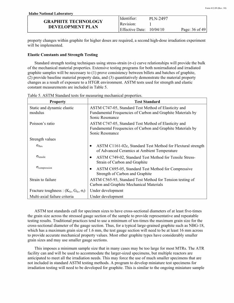
Form 412.09 (Rev. 10)
Idaho National Laboratory
GRAPHITE TECHNOLOGY
DEVELOPMENT PLAN
Identifier: Revision: Effective Date:
PLN-2497 1 10/04/10 Page: 36 of 49
property changes within graphite for higher doses are required, a second high-dose irradiation experiment will be implemented.
Elastic Constants and Strength Testing
Standard strength testing techniques using stress-strain (σ-ε) curve relationships will provide the bulk of the mechanical material properties. Extensive testing programs for both nonirradiated and irradiated graphite samples will be necessary to (1) prove consistency between billets and batches of graphite, (2) provide baseline material property data, and (3) quantitatively demonstrate the material property changes as a result of exposure to a HTGR environment. ASTM tests used for strength and elastic constant measurements are included in Table 5.
Table 5. ASTM Standard tests for measuring mechanical properties.
Property Test Standard
Static and dynamic elastic modulus
ASTM C747-05, Standard Test Method of Elasticity and Fundamental Frequencies of Carbon and Graphite Materials by Sonic Resonance
Poisson’s ratio ASTM C747-05, Standard Test Method of Elasticity and Fundamental Frequencies of Carbon and Graphite Materials by Sonic Resonance
Strength values
σflex
σtensile
σcompression
• ASTM C1161-02c, Standard Test Method for Flextural strength of Advanced Ceramics at Ambient Temperature
• ASTM C749-02, Standard Test Method for Tensile Stress-Strain of Carbon and Graphite
• ASTM C695-05, Standard Test Method for Compressive Strength of Carbon and Graphite
Strain to failure ASTM C565-93, Standard Test Method for Tension testing of Carbon and Graphite Mechanical Materials
Fracture toughness : (KIc, GIc, σf) Under development
Multi-axial failure criteria Under development
ASTM test standards call for specimen sizes to have cross-sectional diameters of at least five-times the grain size across the stressed gauge section of the sample to provide representative and repeatable testing results. Traditional practices tend to use a minimum of ten-times the maximum grain size for the cross-sectional diameter of the gauge section. Thus, for a typical large-grained graphite such as NBG-18, which has a maximum grain size of 1.6 mm, the test gauge section will need to be at least 16 mm across to provide accurate mechanical property values. Most other graphite types have considerably smaller grain sizes and may use smaller gauge sections.
This imposes a minimum sample size that in many cases may be too large for most MTRs. The ATR facility can and will be used to accommodate the larger-sized specimens, but multiple reactors are anticipated to meet all the irradiation needs. This may force the use of much smaller specimens that are not included in standard ASTM testing methods. A program to develop miniature test specimens for irradiation testing will need to be developed for graphite. This is similar to the ongoing miniature sample

Form 412.09 (Rev. 10)
Idaho National Laboratory
GRAPHITE TECHNOLOGY
DEVELOPMENT PLAN
Identifier: Revision: Effective Date:
PLN-2497 1 10/04/10 Page: 37 of 49
development for irradiated metal samples. In either case, careful determination of the optimal sample size is required for each mechanical test before irradiation.
Specialized grips are required for the testing of graphite, as specified in the test standards. This is especially true for miniature test specimens that will require specialized fixtures to accommodate the small size. These specialized fixtures must be identified and developed prior to mechanical testing activities.
Finally, some elastic constants will be obtained using nondestructive UT methods. Standard testing procedures will be used to obtain dynamic elastic modulus values (tensile and compression) for specific samples.
Tribology (wear/friction)
Standard pin-on-wheel wear testing procedures will be used to determine wear, friction, and dust generation values for selected grades of graphite. Previously irradiated and oxidized graphite will be subjected to similar tests to determine any changes. These will be limited studies focused on those graphite types of interest to pebble-bed designs .
5.2 Multiscale Model Development
Models are required to allow the designer to assess the condition of graphite components and core structure design margins at any point in the lifetime of the reactor. The models are needed to describe interactions between graphite components; specifically, the behavior of the stack of graphite blocks making up the core moderator and reflector. Specific models should be able to calculate external loads imposed upon the components, internal stresses resulting from radiation and temperature induced dimensional changes, movement of components (dimensional clearances for control rod insertion), and estimates of residual strength both with and without environmental attack (air-ingress during off-normal event).
Modeling the behavior of a graphite core is complex and will require some fundamental understanding of the graphite physical, thermal, and mechanical behavior as a function of irradiation temperature and neutron fluence. However, the primary objective of these models is to provide the ability to calculate in-service stresses and strains in graphite components and estimate the structural integrity of the core as a whole. Thus, the understanding of fundamental mechanistic material behavior during operation will be limited to those aspects required to understand the response of the entire core, both during normal operation and during off-normal events (e.g., predict seismic behavior of the core). A physics-based understanding of microstructural damage and its effects on materials structure and properties will provide an initial start to estimating the amount of changes to a graphite component. Although it can be estimated, the degree of change is unique to the specific nuclear graphite grade used and these fundamental principles must be supplemented with actual experimental material property data to provide a complete analysis of the core behavior.
For example, the existence of temperature and flux gradients within the core and individual components will generate differential changes in dimensions and, hence, stress. Such stresses will creep out (relax) at the expected temperature and fluence levels experienced during normal operation. In addition, stresses arising because of thermal gradients will also creep out during operation, but will reappear in the opposite sense when the core cools during reactor shutdown. To model the core and component stresses during operation (and cool down), the change in properties of the graphite as a function of temperature and neutron dose must be known. Since the point-to-point flux and temperature
Form 412.09 (Rev. 10)
Idaho National Laboratory
GRAPHITE TECHNOLOGY
DEVELOPMENT PLAN
Identifier: Revision: Effective Date:
PLN-2497 1 10/04/10 Page: 38 of 49
data will not be available for all combinations of dose and temperature for the required properties, behavioral models are required to estimate the stress states for all components throughout the core. Thus, the whole core models must use a combination of experimentally derived material properties underpinned by an understanding of the fundamental physics to account for all variations possible within the graphite components of the core. Consequently, a major goal is the development and validation of multiscale models for the behavior of graphite, core components, and whole graphite cores for use in licensing and continued operational safety assessments.
5.2.1 Whole Graphite Core and Component Behavior Models
Finite element models are required to define the core condition at all times during core life. Such models will take core physics and thermohydraulic inputs for point dose and temperature values and apply graphite material behavior models to calculate the changes in properties with neutron dose, temperature, and oxidative weight loss. Core and component-scale models will allow designers to predict core and core block (e.g., reflector or fuel element) dimensional distortion, component stresses, residual strength, and probability of failure during normal or off-normal conditions.
Finite element-based codes such as COMSOLTM and ABAQUSTM offer platforms upon which the desired whole-core/component-behavioral models may be assembled. It is anticipated that reactor vendors will have their own custom codes to describe and predict the behavior of the core within their particular design for NGNP. However, independent validation of these whole core-scale models may be requested by the NGNP project to ensure the safety envelope of the core during normal and off-normal operating conditions.
Finally, the development and utilization of such codes is an integral part of the design process and is recognized as such by the ASME graphite core components design code, prepared by a subgroup of ASME B&PV Section III (nuclear). The subgroup is currently benchmarking core component stress models against a standard set of problems (data sets). Additional validating data for the developed models will come from large multiaxial load specimen testing and, ultimately, from full-scale core components tests.
5.2.2 Macroscale Materials Behavior Models
Materials behavior models are needed to predict the effects of temperature, neutron dose, and oxidation weight-loss on key physical and mechanical properties. The material behavior results from these models are validated through an extensive program of nonirradiated and irradiation characterization experiments. The properties of interest include:
• CTE and thermal conductivity (specific heat)
• Strength (tensile, compressive, flexural)
• Fracture behavior
• Elastic constants (Young’s modulus, shear modulus, Poisson’s ratio)
• Creep coefficient(s).
The material property models must also take into account the interaction of effects such as neutron damage and weight loss and the interdependency of effects such as stressed dimensional change (creep) on the physical properties of graphite. Materials models must be physically based on the materials structural changes and should incorporate structural damage models and existing physics-based models
Form 412.09 (Rev. 10)
Idaho National Laboratory
GRAPHITE TECHNOLOGY
DEVELOPMENT PLAN
Identifier: Revision: Effective Date:
PLN-2497 1 10/04/10 Page: 39 of 49
such as phonon conduction. Existing material property models, in some cases empirically derived, must be evaluated and new or improved materials behavior models developed. Material property values needed for validation of these models will be obtained from the experimental characterization research, as described above (AGC experiment, nonirradiated property characterization, and possibly high-dose experiments).
Particular emphasis will be placed on this aspect of the multiscale modeling because it is the most directly applicable to the NGNP R&D program. Individual vendor designs are expected to significantly influence the whole core-scale modeling efforts, and as such, the majority of the development effort for whole core-scale models is expected to reside with the vendors. However, as illustrated above, the material property models necessary for predicting graphite component and core behavior will be essential to developing and validating the whole cores-scale models.
5.2.3 Microscale/Nanoscale Models
Nanoscale and microscale modeling provides a fundamental understanding of material behavior. Ab-Initio models of the atomistic phenomena occurring on irradiation will allow prediction of the displacement damage that can occur and may shed light on the crystal deformation modes. Simulations such as Density Function Theory of defect structures for relevant combinations of dose and temperature can provide the basis of determining crystal strains. Understanding the physical interactions of the graphite crystallites and the inherent porosity within and around the crystallites is crucial to building microstructural models for the behavior of polycrystalline graphite. Similarly, the deformation processes that occur within the crystallites when graphite is subjected to stress, either externally applied or those that develop within the graphite because of dose and temperature gradients, must be understood and modeled.
A, after about 60 years of graphite use in reactors, the microstructural mechanism of irradiation creep and crystal deformation are still being questioned and are not fully elucidated. Recent fundamental studies by Heggie et al. (University of Sussex Group, UK), have suggested that displacement damage structures, previously considered improbable, are indeed energetically favorable, indicating the need for further study. Crystallite damage observations using a transmission electron microscope coupled with a scanning electron microscope and CT studies of irradiated graphite will provide mechanistic data for structural models.
As indicated above, development of nanoscale and microscale models will underpin the macroscale materials property models, as well as provide valuable input for experimental validation requirements. However, fundamental studies and microscale modeling should be supportive of the material property models to enable a basic understanding of the mechanisms driving the material property changes. While important, less direct emphasis will be placed on complete development of these nanoscale and microscale models than on the material property models discussed previously. Some support will be required to fully understand the underlying principles that induce changes to the material properties, but the majority of the work will be left to long-range research funding sources.
Form 412.09 (Rev. 10)
Idaho National Laboratory
GRAPHITE TECHNOLOGY
DEVELOPMENT PLAN
Identifier: Revision: Effective Date:
PLN-2497 1 10/04/10 Page: 40 of 49
6. COSTS AND SCHEDULE
Experimental testing and data collection are considered to be the largest costs for the graphite R&D program. As indicated in Sections 4 and 5, the list of required material properties are fairly extensive and the irradiation testing program rather long. The activities supporting licensing - development of whole core models, ASME code development, and NRC licensing reviews - are assumed to be less time and cost intensive; however, the exact activities are less defined leading to uncertainty for appropriate budgets. As a consequence, the costs are broken into two areas: experimental data collection and licensing support.
6.1 Data Collection Costs
The costs for support activities, such as QA, sample procurement/fabrication, and preirradiation tasks, in addition to the actual testing programs, are discussed. The experimental work is further divided into nonirradiated and irradiated tasks to better reflect the development plan in Section 5.0. A brief description of the identified activities and the estimated costs are shown in Table 6, which shows that total costs are a function of the number of graphite types to be investigated, the selected reactor design, and the operating parameters (temperature and dose levels) of the selected reactor. A prismatic design is used for a cost baseline with the assumption that the R&D program will change if a pebble-bed design is selected. A number of variables can adjust the costs for each reactor design as discussed in the following subsections. Major Graphite Program costs are broken down in Table 7 and total costs are summarized in Figure 16.
6.1.1 Prismatic
PCEA graphite has been selected for the prismatic NGNP design, but others may be considered (see NGNP Graphite Selection and Acquisition Strategy) adding to the overall costs. A full thermomechanical characterization program for all graphite types will be required.
6.1.2 Pebble-bed
NBG-18 graphite has been selected for the pebble-bed NGNP design, but others may be considered (see NGNP Graphite Selection and Acquisition Strategy). Graphite irradiations to 25 dpa will be required for front face of reflector blocks, adding to irradiation experiments costs. A partial thermomechanical characterization program for NBG-18 graphite will reduce the overall costs, since PBMR has already performed significant testing in this area.
6.2 Data Collection Schedules
A preliminary schedule for all graphite work has been recently developed. This master schedule incorporates not only the irradiation schedules for AGC, as discussed previously, but also graphite procurement, nonirradiated data collection, and required ASME and NRC licensing effort timelines. This master schedule is presented in modified form in Figure 17.
As shown, the schedule does not incorporate those tasks needed for support of a pebble-bed design selection (high-dose experiments, minimal nonirradiated characterization, or adjustments to the existing irradiation program). The schedule is based on the baseline assumption of a PMR design. Once key design decisions are made by the NGNP project, the schedule and cost baseline will be updated to reflect these decisions and a more detailed resource loaded schedule will be produced.
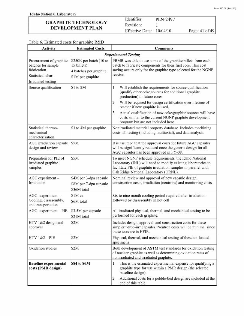
Form 412.09 (Rev. 10)
Idaho National Laboratory
GRAPHITE TECHNOLOGY
DEVELOPMENT PLAN
Identifier: Revision: Effective Date:
PLN-2497 1 10/04/10 Page: 41 of 49
Table 6. Estimated costs for graphite R&D
Activity Estimated Costs Comments
Experimental Testing
Procurement of graphite batches for sample fabrication
Statistical char.
Irradiated testing
$250K per batch (10 to 15 billets)
4 batches per graphite
$1M per graphite
PBMR was able to use some of the graphite billets from each batch to fabricate components for their first core. This cost saving occurs only for the graphite type selected for the NGNP reactor.
Source qualification $1 to 2M 1. Will establish the requirements for source qualification (qualify other coke sources for additional graphite production) in future cores.
2. Will be required for design certification over lifetime of reactor if new graphite is used.
3. Actual qualification of new coke/graphite sources will have costs similar to the current NGNP graphite development program but are not included here..
Statistical thermo-mechanical characterization
$3 to 4M per graphite Nonirradiated material property database. Includes machining costs, all testing (including multiaxial), and data analysis.
AGC irradiation capsule design and review
$5M It is assumed that the approval costs for future AGC capsules will be significantly reduced once the generic design for all AGC capsules has been approved in FY-08.
Preparation for PIE of irradiated graphite samples
$5M To meet NGNP schedule requirements, the Idaho National Laboratory (INL) will need to modify existing laboratories to facilitate PIE of graphite irradiation samples in parallel with Oak Ridge National Laboratory (ORNL).
AGC experiment – Irradiation
$4M per 3-dpa capsule
$8M per 7-dpa capsule
$36M total
Nominal review and approval of new capsule design, construction costs, irradiation (neutrons) and monitoring costs
AGC- experiment – Cooling, disassembly, and transportation
$1M ea
$6M total
Six to nine month cooling period required after irradiation followed by disassembly in hot cell
AGC- experiment – PIE $3.5M per capsule
$21M total
All irradiated physical, thermal, and mechanical testing to be performed for each graphite.
HTV 1&2 design and approval
$2M Includes design, approval, and construction costs for these simpler “drop-in” capsules. Neutron costs will be minimal since these tests are in HFIR.
HTV 1&2 – PIE $2M Physical, thermal, and mechanical testing of these un-loaded specimens
Oxidation studies $2M Both development of ASTM test standards for oxidation testing of nuclear graphite as well as determining oxidation rates of nonirradiated and irradiated graphite.
Baseline experimental costs (PMR design)
$84 to 86M 1. This is the estimated experimental expense for qualifying a graphite type for use within a PMR design (the selected baseline design).
2. Additional costs for a pebble-bed design are included at the end of this table.
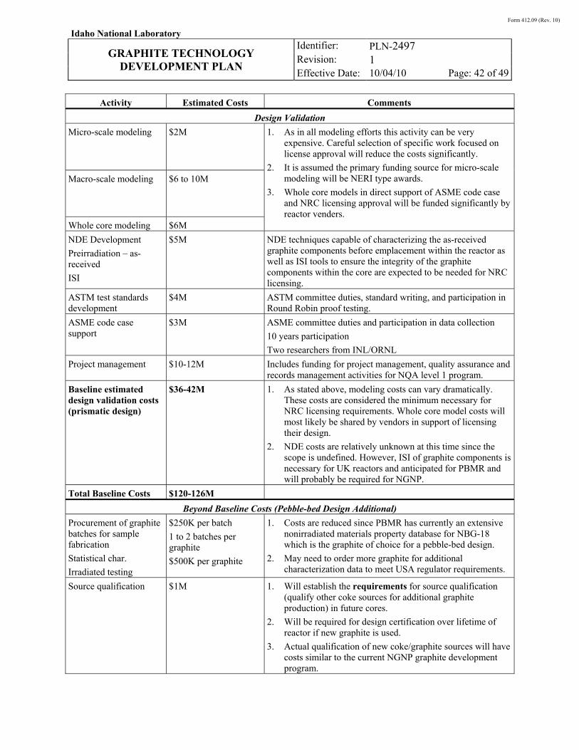
Form 412.09 (Rev. 10)
Idaho National Laboratory
GRAPHITE TECHNOLOGY
DEVELOPMENT PLAN
Identifier: Revision: Effective Date:
PLN-2497 1 10/04/10 Page: 42 of 49
Activity Estimated Costs Comments
Design Validation
Micro-scale modeling $2M 1. As in all modeling efforts this activity can be very expensive. Careful selection of specific work focused on license approval will reduce the costs significantly.
2. It is assumed the primary funding source for micro-scale modeling will be NERI type awards.
3. Whole core models in direct support of ASME code case and NRC licensing approval will be funded significantly by reactor venders.
Macro-scale modeling $6 to 10M
Whole core modeling $6M
NDE Development
Preirradiation – as-received
ISI
$5M NDE techniques capable of characterizing the as-received graphite components before emplacement within the reactor as well as ISI tools to ensure the integrity of the graphite components within the core are expected to be needed for NRC licensing.
ASTM test standards development
$4M ASTM committee duties, standard writing, and participation in Round Robin proof testing.
ASME code case support
$3M ASME committee duties and participation in data collection
10 years participation
Two researchers from INL/ORNL
Project management $10-12M Includes funding for project management, quality assurance and records management activities for NQA level 1 program.
Baseline estimated design validation costs (prismatic design)
$36-42M 1. As stated above, modeling costs can vary dramatically. These costs are considered the minimum necessary for NRC licensing requirements. Whole core model costs will most likely be shared by vendors in support of licensing their design.
2. NDE costs are relatively unknown at this time since the scope is undefined. However, ISI of graphite components is necessary for UK reactors and anticipated for PBMR and will probably be required for NGNP.
Total Baseline Costs $120-126M
Beyond Baseline Costs (Pebble-bed Design Additional)
Procurement of graphite batches for sample fabrication
Statistical char.
Irradiated testing
$250K per batch
1 to 2 batches per graphite
$500K per graphite
1. Costs are reduced since PBMR has currently an extensive nonirradiated materials property database for NBG-18 which is the graphite of choice for a pebble-bed design.
2. May need to order more graphite for additional characterization data to meet USA regulator requirements.
Source qualification $1M 1. Will establish the requirements for source qualification (qualify other coke sources for additional graphite production) in future cores.
2. Will be required for design certification over lifetime of reactor if new graphite is used.
3. Actual qualification of new coke/graphite sources will have costs similar to the current NGNP graphite development program.
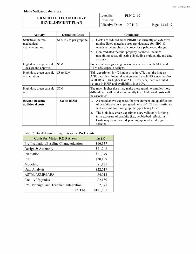
Form 412.09 (Rev. 10)
Idaho National Laboratory
GRAPHITE TECHNOLOGY
DEVELOPMENT PLAN
Identifier: Revision: Effective Date:
PLN-2497 1 10/04/10 Page: 43 of 49
Activity Estimated Costs Comments
Statistical thermo-mechanical characterization
$1.5 to 2M per graphite 1. Costs are reduced since PBMR has currently an extensive nonirradiated materials property database for NBG-18 which is the graphite of choice for a pebble-bed design.
2. Nonirradiated material property database. Includes machining costs, all testing (including multiaxial), and data analysis.
High dose creep capsule – design and approval
$5M Some cost savings using previous experience with AGC and HTV 1&2 capsule designs.
High dose creep capsule – irradiation
$8 to 12M This experiment is 4X longer time in ATR than the longest AGC capsules. Potential savings could use HFIR since the flux in HFIR is ~ 3X higher than ATR. However, there is limited volume in HFIR and availability is at 50%.
High dose creep capsule – PIE
$5M The much higher dose may make these graphite samples more difficult to handle and subsequently test. Additional costs will be associated.
Beyond baseline additional costs
~ $21 to 25.5M 1. As noted above expenses for procurement and qualification of graphite are on a “per graphite basis”. This cost estimate will increase for more graphite types being tested.
2. The high dose creep experiments are valid only for long term exposure of graphite (i.e., pebble-bed reflectors). Costs may be reduced depending upon which design is selected.
Table 7. Breakdown of major Graphite R&D costs.
Costs for Major R&D Areas In $K
Pre-Irradiation/Baseline Characterization $16,137
Design & Assembly $21,248
Irradiation $21,379
PIE $30,199
Modeling $1,131
Data Analysis $22,519
ASTM/ASME/IAEA $4,012
Facility Upgrades $2,130
PM Oversight and Technical Integration $2,777
TOTAL $121,531
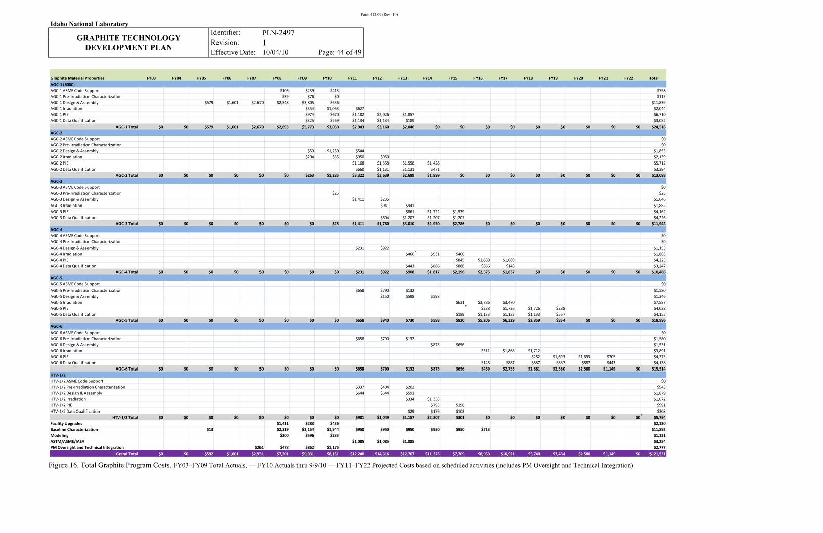
Form 412.09 (Rev. 10)
Idaho National Laboratory
GRAPHITE TECHNOLOGY
DEVELOPMENT PLAN
Identifier: Revision: Effective Date:
PLN-2497 1 10/04/10 Page: 44 of 49
Figure 16. Total Graphite Program Costs. FY03–FY09 Total Actuals, — FY10 Actuals thru 9/9/10 — FY11–FY22 Projected Costs based on scheduled activities (includes PM Oversight and Technical Integration)
Graphite Material Properties FY03 FY04 FY05 FY06 FY07 FY08 FY09 FY10 FY11 FY12 FY13 FY14 FY15 FY16 FY17 FY18 FY19 FY20 FY21 FY22 TotalAGC-1 (600C)AGC-1 ASME Code Support $106 $239 $413 $758AGC-1 Pre-Irradiation Characterization $39 $76 $0 $115AGC-1 Design & Assembly $579 $1,601 $2,670 $2,548 $3,805 $636 $11,839AGC-1 Irradiation $354 $1,063 $627 $2,044AGC-1 PIE $974 $670 $1,182 $2,026 $1,857 $6,710AGC-1 Data Qualification $325 $269 $1,134 $1,134 $189 $3,052
AGC-1 Total $0 $0 $579 $1,601 $2,670 $2,693 $5,773 $3,050 $2,943 $3,160 $2,046 $0 $0 $0 $0 $0 $0 $0 $0 $0 $24,516AGC-2AGC-2 ASME Code Support $0AGC-2 Pre-Irradiation Characterization $0AGC-2 Design & Assembly $59 $1,250 $544 $1,853AGC-2 Irradiation $204 $35 $950 $950 $2,139AGC-2 PIE $1,168 $1,558 $1,558 $1,428 $5,712AGC-2 Data Qualification $660 $1,131 $1,131 $471 $3,394
AGC-2 Total $0 $0 $0 $0 $0 $0 $263 $1,285 $3,322 $3,639 $2,689 $1,899 $0 $0 $0 $0 $0 $0 $0 $0 $13,098AGC-3AGC-3 ASME Code Support $0AGC-3 Pre-Irradiation Characterization $25 $25AGC-3 Design & Assembly $1,411 $235 $1,646AGC-3 Irradiation $941 $941 $1,882AGC-3 PIE $861 $1,722 $1,579 $4,162AGC-3 Data Qualification $604 $1,207 $1,207 $1,207 $4,226
AGC-3 Total $0 $0 $0 $0 $0 $0 $0 $25 $1,411 $1,780 $3,010 $2,930 $2,786 $0 $0 $0 $0 $0 $0 $0 $11,942AGC-4AGC-4 ASME Code Support $0AGC-4 Pre-Irradiation Characterization $0AGC-4 Design & Assembly $231 $922 $1,153AGC-4 Irradiation $466 $931 $466 $1,863AGC-4 PIE $845 $1,689 $1,689 $4,223AGC-4 Data Qualification $443 $886 $886 $886 $148 $3,247
AGC-4 Total $0 $0 $0 $0 $0 $0 $0 $0 $231 $922 $908 $1,817 $2,196 $2,575 $1,837 $0 $0 $0 $0 $0 $10,486AGC-5AGC-5 ASME Code Support $0AGC-5 Pre-Irradiation Characterization $658 $790 $132 $1,580AGC-5 Design & Assembly $150 $598 $598 $1,346AGC-5 Irradiation $631 $3,786 $3,470 $7,887AGC-5 PIE $288 $1,726 $1,726 $288 $4,028AGC-5 Data Qualification $189 $1,133 $1,133 $1,133 $567 $4,155
AGC-5 Total $0 $0 $0 $0 $0 $0 $0 $0 $658 $940 $730 $598 $820 $5,206 $6,329 $2,859 $854 $0 $0 $0 $18,996AGC-6AGC-6 ASME Code Support $0AGC-6 Pre-Irradiation Characterization $658 $790 $132 $1,580AGC-6 Design & Assembly $875 $656 $1,531AGC-6 Irradiation $311 $1,868 $1,712 $3,891AGC-6 PIE $282 $1,693 $1,693 $705 $4,373AGC-6 Data Qualification $148 $887 $887 $887 $887 $443 $4,138
AGC-6 Total $0 $0 $0 $0 $0 $0 $0 $0 $658 $790 $132 $875 $656 $459 $2,755 $2,881 $2,580 $2,580 $1,149 $0 $15,514HTV-1/2HTV-1/2 ASME Code Support $0HTV-1/2 Pre-Irradiation Characterization $337 $404 $202 $943HTV-1/2 Design & Assembly $644 $644 $591 $1,879HTV-1/2 Irradiation $334 $1,338 $1,672HTV-1/2 PIE $793 $198 $991HTV-1/2 Data Qualification $29 $176 $103 $308
HTV-1/2 Total $0 $0 $0 $0 $0 $0 $0 $0 $981 $1,049 $1,157 $2,307 $301 $0 $0 $0 $0 $0 $0 $0 $5,794Facility Upgrades $1,411 $283 $436 $2,130Baseline Characterization $13 $2,319 $2,154 $1,944 $950 $950 $950 $950 $950 $713 $11,893Modeling $300 $596 $235 $1,131ASTM/ASME/IAEA $1,085 $1,085 $1,085 $3,254PM Oversight and Technical Integration $261 $478 $862 $1,175 $2,777
Grand Total $0 $0 $592 $1,601 $2,931 $7,201 $9,931 $8,151 $12,240 $14,316 $12,707 $11,376 $7,709 $8,953 $10,921 $5,740 $3,434 $2,580 $1,149 $0 $121,531
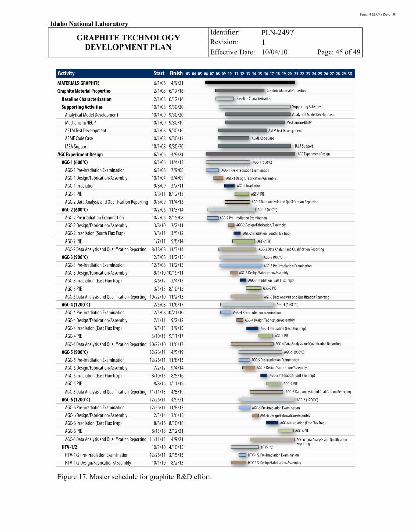
Form 412.09 (Rev. 10)
Idaho National Laboratory
GRAPHITE TECHNOLOGY
DEVELOPMENT PLAN
Identifier: Revision: Effective Date:
PLN-2497 1 10/04/10 Page: 45 of 49
Figure 17. Master schedule for graphite R&D effort.
Form 412.09 (Rev. 10)
Idaho National Laboratory
GRAPHITE TECHNOLOGY
DEVELOPMENT PLAN
Identifier: Revision: Effective Date:
PLN-2497 1 10/04/10 Page: 46 of 49
7. LONGER TERM CONSIDERATIONS
What is presented above is a minimal baseline estimate for performing the required graphite R&D for the NGNP. Some discussion of each is warranted about longer-term issues that would impact the longer R&D program needed for ultimate commercialization of the HTGR technology.
7.1 Graphite Acquisition Plan
Currently, the world market share for nuclear graphite is extremely small. While graphite manufacturers are willing to produce nuclear grade graphite, the petroleum industry, which produces the raw starting material (specialty coke) is much less interested. The material specifications for specialty coke are much more exacting than that which is needed for electrode production, which is currently the majority market share for graphite. Since this material’s market share is so small, the coke suppliers have very little financial interest in changing their production process to enable manufacture of these small batches of specialty coke necessary for nuclear graphite production.
As a consequence, there may not be enough specialty coke material needed for initial or sustained production of nuclear graphite for HTGR applications. Obviously, this can significantly affect the graphite R&D schedule if multiple batches of graphite are required for testing and qualification (see Table 5). This potential shortage of coke sources is addressed in detail within the NGNP Graphite Selection and Acquisition Strategy.v
For full commercialization of the HTGR graphite technology in the long term, a more complete evaluation of the processing route and raw material (e.g., coke source) constituent’s influence on graphite behavior is required. The magnitude of the R&D program necessary to establish a standard nuclear grade graphite for a broad range of qualified coke sources for use within any HTGR design cannot be firmly estimated today given the current limited knowledge of the linkage between graphite fabrication, material properties, and in-reactor performance. It is anticipated that the work proposed to qualify graphite for the initial NGNP cores in Section 5 will provide the strong technical basis needed to establish a long-term graphite development and qualification program that meets this more ambitious commercialization goal.
7.2 Graphite Disposition and Recycle Options
Currently, the National Spent Nuclear Fuel Program and the Office of Civilian Radioactive Waste Management will be disposing of Fort St. Vrain and Peach Bottom fuel blocks. The C14 and Cl36 loading from these fuel blocks is insignificant compared to isotope inventories from commercial fuel’s long-lived fission products and transuranics. Graphite reflector blocks from Fort St. Vrain were disposed in a lower-level radioactive landfill. Only Europe faces federal controls on C14 and Cl36 loading in graphite.
Currently, there is no federal guidance on recycling irradiated graphite. Recycling irradiated graphite will depend on a number of factors, including, the number of HTGRs (volume of graphite generated), the ability to decontaminate irradiated graphite, the performance of recycled graphite, and the total cost of recycling. It is expected that as the volume of irradiated graphite grows because of more HTGRs in operation, the cost-to-benefit ratio of graphite recycle will become more favorable.
Euratom has begun development of a decontaminating processes where the C14 is removed from along the grain boundaries of irradiated graphite using a heated oxygen gas. The contaminated gas is captured, and the clean blocks are ready for LLW disposal or possible recycling. Complete decontamination of graphite to below LLW thresholds (crushing plus chemical means) is possible but expensive. Once the graphite has been decontaminated, two recycling options are currently envisioned:

Form 412.09 (Rev. 10)
Idaho National Laboratory
GRAPHITE TECHNOLOGY
DEVELOPMENT PLAN
Identifier: Revision: Effective Date:
PLN-2497 1 10/04/10 Page: 47 of 49
(a) reuse of blocks after heat treatment to anneal out radiation damage, or (b) form new blocks using reconstituted graphite material by crushing and jet milling irradiated blocks to fine powder.
Once a successful technology is developed for decontaminating graphite, the primary issue for recycling is the irradiation performance of the recycled graphite. A new qualification program will be necessary to validate the performance of this recycled graphite source, either for reuse of blocks or reconstituted material.
Form 412.09 (Rev. 10)
Idaho National Laboratory
GRAPHITE TECHNOLOGY
DEVELOPMENT PLAN
Identifier: Revision: Effective Date:
PLN-2497 1 10/04/10 Page: 48 of 49
8. REFERENCES i. L. W. Hobbs, F. W. Clinard Jr., S. J. Zinkle, and R. C. Ewing, “Radiation effects in ceramics,” J. Nuc.
Mater., Vol. 216, 1994, pp. 291–321.
ii. T. D. Burchell, W. P. Eatherly, and J. P. Strizak, “The effect of neutron irradiation on the structure and properties of carbon-carbon composite materials,” Effects of Radiation on Materials: 16th International Symposium, ASTM STP 1175, eds. K. S. Arvid, D. S. Gelles, and R. K. Nanstad, American Society for Testing and Materials, Philadelphia, 1993.
iii. W. N. Reynolds, Radiation Damage in Graphite, Pergamon, New York, 1965, pp. 121–196.
iv. W. V. Geoddel and J. N. Siltanen, “Materials for High Temperature Nuclear Reactors,” Annul. Rev. Nucl. Sci, Vol. 17, 1967, pp. 189–250.
v. R. Bratton and W. Windes, NGNP Graphite Selection and Acquisition Strategy, ORNL/TM-2007/153-10-07 (INL/MIS-10-19427), Oak Ridge National Laboratory, July 28, 2010.
vi. NUREG/CR-6944, “Next Generation Nuclear Plant Phenomena Identification and Ranking Tables (PIRTs),” Vol. 1-6, http://www.nrc.gov/reading-rm/doc-collections/nuregs/contract/cr6944/.
vii. N. C. Gallego, T. D. Burchell, and M. Srinivasan, “Milestone Report on the Workshop on Nuclear Graphite Research,” ORNL/NRC/LTR-09-03, Oak Ridge National Laboratory, 2009.
viii. J. H. W. Simmons, “The effects of irradiation on the mechanical properties of graphite,” Proc. 3rd Conf. Carbon, Buffalo, 1957, pp. 559–68.
ix. B. J. Price and J. C. Bokros, “Dimensional changes in graphite irradiated between 500 and 1100ºC,” Carbon [5] (1967) pp. 73–84.
x. T. D. Burchell, “Fission Reactor Applications of Carbon,” In Carbon Materials for Advanced Technologies, Chpt. 13, pp. 429-484, T. D. Burchell (Editor), Pub. Elsevier Science, 1999.
xi. G. B. Engle and W. P. Eatherly, “Irradiation Behavior of. Graphite at High Temperature,” High Temperatures-High Pressures, Vol. 1, 1972, pp. 119–158.
xii. G. Haag, "Thermal Conductivity of Graphite Irradiated With Medium and High Neutron Fluences,” Proceedings of International Congress on Advances in Nuclear Power Plants (ICAPP’03), Paper 3094, Córdoba, Spain, May 4-7, 2003.
xiii. IAEA report, Irradiation Damage in Graphite because of Fast Neutrons in Fission and Fusion Systems, IAEA-TECDOC-1154, April 2000.
xiv. T. D. Burchell and W. P. Eatherly, “The effects of radiation damage on the properties of GraphNOL N3M,” J. Nuc. Mater., Vols. 179–181, 1991, pp. 205–208.
xv. P. Strizak, T. D. Burchell, and W. Windes, Status of Initial Assessment of Physical and Mechanical Properties of Graphite Grades for NGNP Applications, ORNL-GEN4/LTR-06-023, September 5, 2006.
xvi. M. Carroll, “Mechanical Test Plan,” INL-PLN-3348, Idaho National Laboratory, July 22, 2010.
xvii. M. Carroll, “Baseline Graphite Characterization Plan : Electromechanical Testing,” INL-PLN-3467, Idaho National Laboratory, June 2, 2010.

Form 412.09 (Rev. 10)
Idaho National Laboratory
GRAPHITE TECHNOLOGY
DEVELOPMENT PLAN
Identifier: Revision: Effective Date:
PLN-2497 1 10/04/10 Page: 49 of 49
xviii. T. Burchell, D. Heatherly, J. McDuffee, D. Sparks, and K. Thoms, Experimental Plan and Final
Design Report for HFIR High Temperature Graphite Irradiation Capsules HTV-1 and -2, ORNL-GEN4/LTR-06-019, August 31, 2006.