Embed Size (px)
Citation preview

s
enables tobe derivedd indicateechanical
), to reflecture of ansubstituteerent typesplicationse theory,i, 1979), inpioneers
establishedre to the
. Engi-r to the
European Journal of Mechanics A/Solids 24 (2005) 974–986
Graph theoretical duality perspective on conjugate structureand its applications
N. Ta’aseh, O. Shai∗
Department of Solid Mechanics, Materials and Structures, Tel Aviv University, Tel Aviv 69978, Israel
Received 16 July 2004; accepted 25 March 2005
Available online 17 June 2005
Abstract
The paper shows that representing structures, beams and frames by mathematical models based on graph theoryprovide new perspective on known conjugate structure theorems in mechanics. It is shown that the latter theorems canfrom the graph theoretical duality principle applied upon the graph representations of the structures. The results reporteupon theoretical value of the approach, as the established mathematical foundation can be employed in a variety of mdisciplines. 2005 Elsevier SAS. All rights reserved.
Keywords:Conjugate structures; Duality; Graph representations; Structures; Graph theory
1. Introduction
The approach adopted in this paper uses discrete mathematical models, called graph representations (Shai, 2001the structure, behavior and properties of the engineering systems from various engineering disciplines. The structengineering system is transformed into a graph augmented by additional mathematical properties, thus enabling tothe process of reasoning over the engineering system by reasoning over the corresponding graph representation. Diffof graph representations have been studied and developed upon a thorough investigation of different graph theory apto engineering that were reported in the literature. The main engineering domains that were examined are: machinwhere graph representations have been used for analysis and enumeration of mechanisms (Freudenstein and Makdynamics for analysis of multidimensional dynamic systems (McPhee, 1996), and in structural mechanics where theare Fenves and Branin (1963).
Current paper takes advantage of the relation between graph representations and skeletal structures that has beenin Fenves (1966), Kaveh (1991), Wang and Bjorke (1991), Ta’aseh and Shai (2002). The duality relation is applied hegraph representation of the skeletal structure, resulting in a systematic derivation of the conjugate theorems.
The term duality that is employed in this paper is widely used in the literature for defining several different issuesneering and science account for a number of known duality principles (Girvin, 1996) that may intuitively seem simila
* Corresponding author.E-mail address:[email protected] (O. Shai).
0997-7538/$ – see front matter 2005 Elsevier SAS. All rights reserved.doi:10.1016/j.euromechsol.2005.03.007
N. Ta’aseh, O. Shai / European Journal of Mechanics A/Solids 24 (2005) 974–986 975
otion foronsiderede is thewhichhe math-matrices.ular has
rks andnt, 1991;two types
s relationty is alsoe duality
ering andthe termhe claims68) wheree behaviord to other1).
e variousresentingr analysissai et al.,
rform thecomputerlogy and
plicationsyet been
ther graphwhich thisystem, the
Nomenclature
asterisk* duality transformationA angulardL segment of infinitesimal length� potential difference/belonging to potential
graph��(G) vector of potential differences in graphGE modulus of elasticityF flow/belonging to flow graph�F(G) vector of flows in graphGFS dependent flow source edgeGF Flow Graph Representation (FGR)
G� Potential Graph Representation (PGR)GR Graph RepresentationH hybrid relation matrixI moment of inertiaL linearP external forcePS dependent potential source edgeΠ potential measuring edgeR resistance relation matrixR resistance edge
duality underlying this paper, but actually possess different mathematical basis. In order to avoid confusion, a special nthis term is provided in this paper. Two such principles should be mentioned here, as they are sometimes mistakenly cto coincide with the approach adopted in this paper. One of the widely known duality principles in engineering practicstatical-kinematical duality (McGuire and Gallagher, 1979). This principle finds its origin in the virtual work theoremsresult in the orthogonality between the kinematic and static variables underlying the behavior of the same structure. Tematical basis in this case is linear algebra, and the relation can be traced through similarities in the correspondingRigorous discussion of the role of the duality principle in mathematics in general and discrete mathematics in particbeen conducted in Recski (1989), Iri and Recski (1982).
The principle of duality is also widely used in screw theory (Phillips, 1984), and in the aspect of mechanical netwoscrew theory (Davies, 1983). The duality relation is also used between serial and parallel manipulators (Waldron and HuGosselin and Lallemand, 2001). These works show that the equations underlying the kinematics and statics of theseof manipulators are the same, which makes these two systems to be dual to each other. An in-depth study of thicontributed to a better understanding of the properties of parallel and serial manipulators (Duffy, 1996). The term dualiwidely used in projective geometry where a line corresponds to a point (Pedoe, 1963) and was employed to prove thbetween plane trusses and grillages (Tarnai, 1989).
2. Graph Representations and relations between them
The representations were developed after a thorough investigation on the use of linear graph theory in enginecombining the results of several central works done in the field. In order to avoid confusion, it should be noted that‘graph representation’ refers in this paper only to the models developed on the basis of the linear graph theory, so tmade here should not be automatically projected upon other fields employing this term, such as flowgraphs (Ward, 19a graph represents a system of equations (Lorens, 1964). The graphs used in the paper comprise the information on thof the engineering systems in additions to their structure thus the equations are derived directly from the graph opposetypes of graphs appearing in the literature, including block diagrams (Cha et al., 2000) and bond graphs (Paynter, 196
The use of graph theory in engineering is well known, and this paper employs some of the results developed in thengineering disciplines, such as: electricity – the works of Kron (1963), Seshu and Reed (1961) and others for repand analysis of electrical circuits; In machine theory – the graphs were used to represent linkages and gear trains foor enumeration, such as: Freudenstein (Dobrjanskyj and Freudenstein, 1967; Freudenstein and Maki, 1979), Tsai (T1998); in dynamics the graphs that were used to represent multidimensional dynamic systems upon which to peanalysis (Andrews, 1971; McPhee, 1996); in structural mechanics – network graphs were studied in order to developsoftware for analysis (Fenves and Branin, 1963) who implemented the first computer program from the network topograph algorithms (Fenves et al., 1965).
Representing different engineering systems with bond graphs (Paynter, 1961) also yielded a variety of practical apincluding simulation (Wilson, 1992) and design (Finger and Rinderle, 2002). Bond graph representation has notincorporated within the work introduced in this paper, as till now it has focused on employing linear graph theory.
Graph Representation is basically a graph augmented by special mathematical properties and by relations to orepresentations. Each type of graph representation can be used to represent a number of engineering domains, torepresentation is related through special construction rules (Shai, 2001). When applied to represent an engineering s

976 N. Ta’aseh, O. Shai / European Journal of Mechanics A/Solids 24 (2005) 974–986
f the graph.ow Graphh and Shai,
tween one
aspects
he rule
Formally,
h edge inespondinging edge
s and thentation ofFGR and
aper.
Ta’asehtion 1, theGR. The
ual FGR
nd Shai,sentation
elements and properties of the system are mapped, in an isomorphic manner, into the elements and the properties orepresentation. Graph Representations are classified into several types, in accordance to their augmented properties
Current paper focuses on only three types of graph representations: Potential Graph Representation (PGR), FlRepresentation (FGR) and the Resistance Graph Representation (RGR). In previous publications (Shai, 2001; Ta’ase2002) these representations were shown to be applicable to represent various forms and aspects of structures.
It was shown and proved (Shai, 2001) that the three representations possess strong mathematical relations beanother:
Relation 1. RGR contains properties of both FGR and PGR. In other words, PGR and FGR reflect two differentcomprising RGR. This property will be extensively elaborated in Section 4.
Relation 2. Graph duality property (Swamy and Thulasiraman, 1981) yields a duality relation between PGR and FGR. Tunderlying this relation can be stated as follows: for each graphG� of type PGR, there exists a dual graphGF of type FGR, sothat the potential differences of the edges of the former are equal to the flows in the corresponding edges of the latter.this is expressed as:
(GF)∗ = G�,
�F(GF) = ��(
G�)
where asterisk superscript stands for the duality transformation,�F(GF) is the vector of flows inGF, and ��(G�) – vector ofpotential differences inG�.
The properties of the duality relation, as were established in Shai (2001), can be summarized as follows: for eacPGR there exists a corresponding edge in its dual FGR; for each vertex in one graph representation there is a corrface in the dual representation; the flow through an edge in FGR is equal to the potential difference of the correspondin the dual PGR; for each cutset in one representation there exists a dual circuit in the dual representation.
General description of a structure usually requires to list all the mathematical equations underlying both the statickinematics of the system, thus it can fully be represented by means of RGR. Through Relation 1 the graph represethe structure can be reduced to either PGR and FGR. The possibility of constructing the dual representations of thesePGR and then interpreting them as representations of some other engineering systems is examined throughout this p
3. Representing beams with graph representations and deriving the conjugate beam theorem
The aim of this section is to develop an engineering system that is dual to a general beam. As it was reported inand Shai (2002), the representation suitable for a beam is the Resistance Graph Representation (RGR). Using RelaRGR of a beam can be reduced to a PGR. Then, the duality Relation 2 can be applied to build the FGR dual to this Pobtained FGR would be interpreted as an engineering system – the dual system of the original beam.
In this paper the original structure (a beam or a frame), is represented by PGR which is then transformed into the dof the corresponding dual system.
3.1. Resistance graph representation of a beam
The approach in this section is applied to the beam shown in Fig. 1. Throughout the paper it will be referred to asthe originalbeam.
Firstly, the RGR of the beam is shortly explained on the basis of the previous work done by the authors (Ta’aseh a2002). The representation will first be developed for a single infinitesimal segment of the engineering system. The repreof the whole system will then be obtained by interconnecting the representations of the segments.
Fig. 1. The original beam to which the approach is applied.
N. Ta’aseh, O. Shai / European Journal of Mechanics A/Solids 24 (2005) 974–986 977
displace-
pre-
whileand thecceptede angular
dnoted
ions of thebeam aree flow oftively.on
endthe
ese sources
t
g variablesin the graphpt R.
e
defined
relationraph.
Fig. 2. Resistance graph of an infinitesimal beam segment. (a) Linear force. (b) Linear displacement. (c) Angular force. (d) Angularment. (e) The corresponding resistance graph.
A horizontal beam segment of an infinitesimal length, dL, shown in Fig. 2(a)–(d) with the corresponding variables is resented by the RGR shown in Fig. 2(e). The graph, related to the segment dL, is composed of two parts: a linear graph,LGdL,and an angular graph,AGdL (throughout the paper, the rear-superscript ‘L’ will stand for linear, or translational aspects,‘A’ will stand for angular, or rotational aspects). The linear graph deals with representing the translational deformationslinear forces of the segment. It should be noted that in this paper the term ‘linear graph’ differs in its meaning from the ameaning in graph theory, for example in Deo (1974). The angular graph, in contrast to the linear graph, represents thdeformation and the bending moment (angular force) of the segment.
In the beam segment of Fig. 2, linear forces and displacements are directed in parallel to they axis, while angular forces andisplacements are directed in parallel to thez axis. Therefore, each of the two graphs is one-dimensional and will be deby its relevant dimension in the subscript,LGdLy andAGdLz as is shown in Fig. 2(e).
Both graphs contain an edge representing the segment, the end vertices of which correspond to the interconnectsegment to its neighbor segments. The two sides of the segment with which the segment interfaces to the rest of thearbitrary assigned to be the tail side (or joint) and the head side (or joint) of the segment. The potential difference and ththe segment edge in the angular graph,AGdLz, correspond to relative angular deflection and the bending moment, respecThe potential difference and the flow of the segment edge in the linear graph,LGdLy , correspond to the relative linear deflecti
and the shear force, respectively. Additionally, the angular graph,AGdLz, contains an auxiliary edge connecting one of thevertices of the segment edge to the reference vertex denoted by ‘o’. The purpose of the auxiliary edge is to account formoment produced by the shear force of the segment.
As can be seen from Fig. 2, the two graphs are related through dependent sources designated by CP and CF. Thforce the following relations between the variables of the two graphs:
Potential-Controlled Potential Source (PCPS, or CP in short):
L�CPdLy = H�
dLyz · A�CFdLz with H�
dLyz = −dLx (1)
whereL�CPdLy
is the potential difference in the dependent potential difference source in the linear graph, andA�CFdLz
is thepotential difference in the dependent flow source edge in the angular graph.
Flow-Controlled Flow Source (FCFS, or CF in short):
AFCFdLz = HF
dLzy · LFCPdLy with HF
dLzy = dLx. (2)
WhereAFCFdLz
is the flow in the dependent flow source edge in the angular graph, andLFCPdLy
is the flow in the dependenpotential difference edge in the linear graph.
The elastic properties of the segment are expressed through the resistance relation between the correspondinin the segment edge in the angular graph. Since only the angular segment edges possess the resistance relationrepresentation of beams, in the paper these edges will be referred as ‘resistance’ edges and designated by superscri
A�RdLz = ARR
dLz · AFRdLz,
ARRdLz = dL
EIz. (3)
WhereA�RdLz
is the potential difference of the resistance edge in the angular graph, andAFRdLz
is the flow in the resistanc
edge in the angular graph.ARRdLz
is the resistance of the resistance edge in the angular graph – a constant whose value isin (3).
Due to the properties of the infinitesimal beam segment (McGuire and Gallagher, 1979), there is no resistancebetween the linear deformation and the shear force of the segment, thus there are no resistance edges in the linear g

978 N. Ta’aseh, O. Shai / European Journal of Mechanics A/Solids 24 (2005) 974–986
sentationent showne graphs
elated to, will turnting edge.
f Fig. 2,thus itsnoted byex ofce graph byese edges,h by means
am. Ad-ependent
ined bys should
shown in
its angularnce (grey)
ce can
Fig. 3. Linear and angular FGR of a beam segment.
Fig. 4. Linear and angular PGR of a beam segment.
3.2. Reduction of the beam resistance graph to potential and flow graphs
According to Relation 1, RGR can be seen as a combination of two fundamental components: Potential Graph Repre(PGR) and Flow Graph Representation (FGR). Current section uses this relation to reduce the RGR of the beam segmabove into these two fundamental graph representations. The duality relation (Relation 2) will then be applied to thesin order to enable finding the engineering system dual to the beam.
The FGR corresponding to the beam segment is the graph shown in Fig. 3, resulting from eliminating properties rpotential-differences from the resistance graph appearing in Fig. 2. This way, the potential difference source edge, CPinto a simple flow-conducting edge. The resistance edge, R, in the angular graph also becomes a simple flow-conducConsequently, Eq. (2) is the only relation associated with the Flow Graph Representation of the beam segment.
Similarly, the PGR corresponding to the beam is obtained by eliminating flow properties from the resistance graph oas shown in Fig. 4. The flow in theCF edge is of no relevance, and since this edge is connected to the reference vertex,potential difference is equal to the angular potential of the tail vertex of the resistance edge, and therefore will be deAΠ. In sake of symmetry, a similar edge,LΠ, is added to the linear graph to “measure” the linear potential of the tail vertthe segment edge. The potential difference in the resistance edge of the angular graph was determined in the resistanthe flow through that edge. Since in PGR the flows through the edges are disregarded, the potential differences in thas far as PGR is concerned, are considered as constant potential sources, and are calculated upon building the grapof Eq. (4):
A��dLz = ARR
dLz · AFRdLz. (4)
WhereAFRdLz
are the flows obtained in the corresponding edge upon solution of the flow graph representation of the beditional relation relevant to the potential graph representation of the segment is the relation ruling the behavior of the dpotential difference source, given in Eq. (1).
As was mentioned above, the duality application is sought for through the PGR of the original beam, which is obtaconnecting the graphs of all its segments. The PGR of the beam appearing in Fig. 1 is shown in Fig. 5. Following issuebe noted with regard to this graph:
(1) Although the beam is composed of infinite number of segments and so is its representation, only 4 segments arethe figure for clarity.
(2) The left-most edge corresponds to the left segment of the beam that is connected to the fixed support. Therefore,and linear displacements are equal to zero, thus the corresponding edge is connected directly to the general referevertex.
(3) The external load,P, applied to the right end of the beam is not expressed explicitly in the graph, although its influenbe traced through the angular potential difference sources, whose values are determined through the flow graph.
N. Ta’aseh, O. Shai / European Journal of Mechanics A/Solids 24 (2005) 974–986 979
n for then is doned throughs in graysociated
dual edge
g system.edges,the beam
esses thepaper asrformed.rm7.he linearexample,s. Table 1bles of thedistinction
w depen-
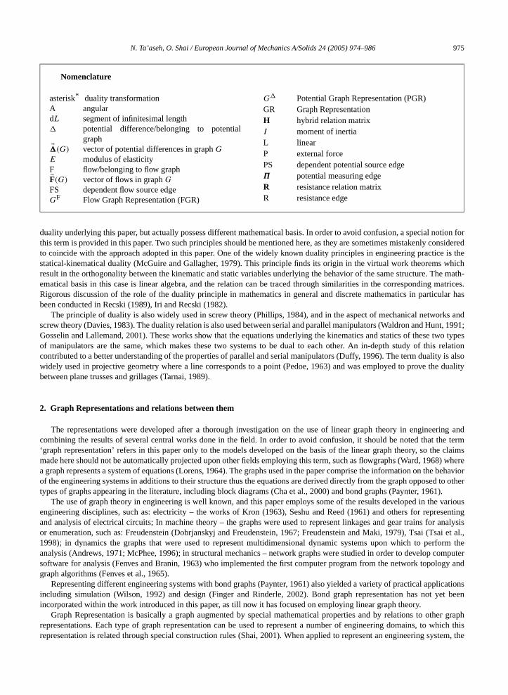
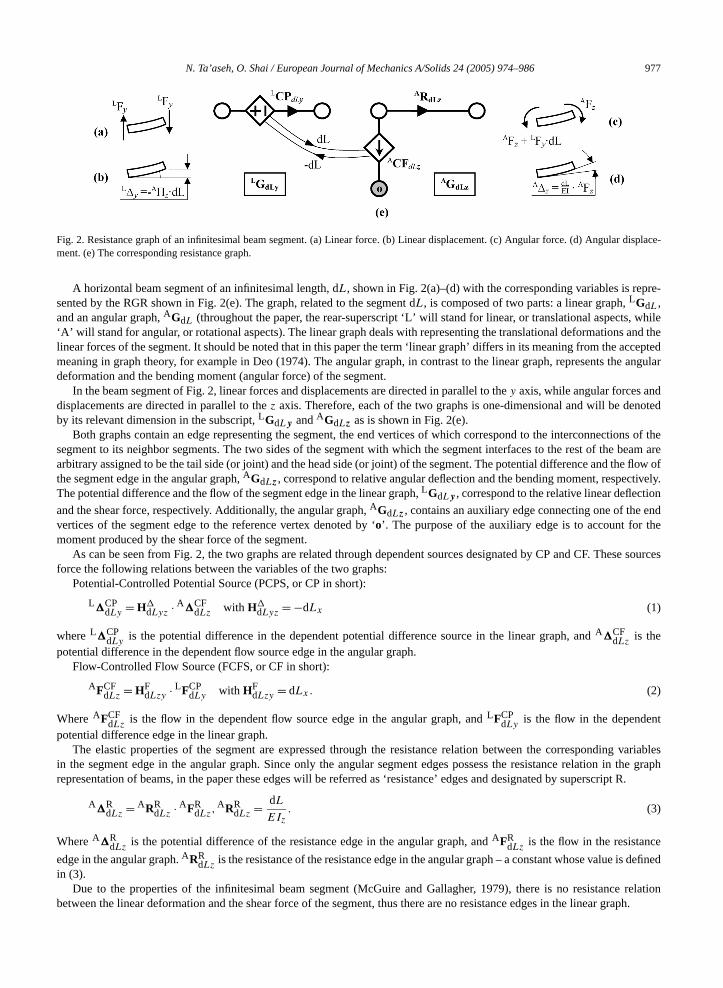
Fig. 5. Linear and angular potential graph representations of the beam.
Fig. 6. The dual FGR superimposed over the original PGR of the beam.
3.3. Constructing the dual flow graph from the potential graph of the original beam
We shall now apply Relation 2 (Section 2) to the Potential Graph Representation obtained in the previous sectiooriginal beam and derive its dual Flow Graph Representation. The transformation to the dual graph representatiothrough the rules corresponding to Relation 2 described in Section 2. The dual Flow Graph Representation obtaineapplying the transformation rules to the Potential Graph representation of Fig. 5 is shown in Fig. 6, where it appearsuperimposed upon the original potential graph. According to the PGR-FGR duality, the potential difference value aswith each original edge is equal to the flow value associated with the corresponding dual edge. The direction of eachis determined by the direction of the corresponding original edge according to the right hand rule.
3.4. The mechanical interpretation of the dual flow graph representation
Current section examines the FGR obtained in the previous section for correspondence with some known engineerinIt follows from Fig. 6 that the dual flow graph, like the original potential graph, is composed of a series of infinitesimaland each such edge is accompanied with a flow-controlled flow source. The beam segment flow graph reduced fromRGR (Fig. 2) also includes an infinitesimal segment edge accompanied with a flow-controlled flow source, and posssame topology. This indicates that the dual flow graph is itself an FGR of some other beam which will be referred in thethe dual beam. In the continuation of this section, the process of deducing this beam from its graph representation is pe
For convenience, the directions of the flow source edges of the dual graph, (AG�z )∗, are altered to match the general fo
of the Flow Graph Representation of the beam, without loss of consistency with the original system, as shown in Fig.From comparing the graphs appearing in Fig. 7 with those appearing in Fig. 3, it can be argued that the dual of t
PGR corresponds to an angular FGR, and the dual of the angular PGR corresponds to a linear FGR. Following thisone can straightforwardly deduce the relations between the variables of the original and the dual beam representationlists the correspondence between the terms and the variables of the two representations. The notations for the variadual beam representation are the same as for the original one, but are augmented with asterisk in order to enablebetween the two.
Fig. 8 shows the graph of Fig. 7 with the edges denoted with the notations introduced in Table 1.Using Table 1, the potential dependence relation (Eq. (1)) associated with the original PGR, can now become a flo
dence relation in the dual FGR, as follows:AF∗CF = H∗F · LF∗CP. (5)
dLy dLyz dLz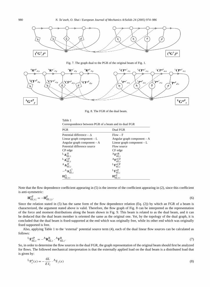
980 N. Ta’aseh, O. Shai / European Journal of Mechanics A/Solids 24 (2005) 974–986
oefficient
beam isesentationnd it canraph, it isriginally
lated as
analyzedoad that
Fig. 7. The graph dual to the PGR of the original beam of Fig. 1.
Fig. 8. The FGR of the dual beam.
Table 1Correspondence between PGR of a beam and its dual FGR
PGR Dual FGR
Potential difference –� Flow – FLinear graph component – L Angular graph component – AAngular graph component – A Linear graph component – LPotential difference source Flow sourceCP edge CF edgeL�Π
dLyAF∗R
dLy
L�CPdLy
AF∗CFdLy
A�ΠdLz
LF∗CPdLz
−A��1
dLzLF∗P
dLz
H�dLyz
H∗FdLyz
Note that the flow dependence coefficient appearing in (5) is the inverse of the coefficient appearing in (2), since this cis anti-symmetric:
H∗FdLyz = −HF
dLzy. (6)
Since the relation stated in (5) has the same form of the flow dependence relation (Eq. (2)) by which an FGR of acharacterized, the argument stated above is valid. Therefore, the flow graph of Fig. 8 can be interpreted as the reprof the force and moment distributions along the beam shown in Fig. 9. This beam is related to as the dual beam, abe deduced that the dual beam member is oriented the same as the original one. Yet, by the topology of the dual gconcluded that the dual beam is fixed-supported at the end which was originally free, while its other end which was ofixed supported is free.
Also, applying Table 1 to the ‘external’ potential source term (4), each of the dual linear flow sources can be calcufollows:
LF∗PdLz = −ARR
dLz · AFRdLz. (7)
So, in order to determine the flow sources in the dual FGR, the graph representation of the original beam should first befor flows. The followed mechanical interpretation is that the externally applied load on the dual beam is a distributed lis given by:
LP∗z (x) = − dL · AFz(x) (8)
EIz
N. Ta’aseh, O. Shai / European Journal of Mechanics A/Solids 24 (2005) 974–986 981
ual beam,
internalsegment.al beam.
nt section
he
e
, throughbeam has
mon axism.
d demon-is
R shownually the
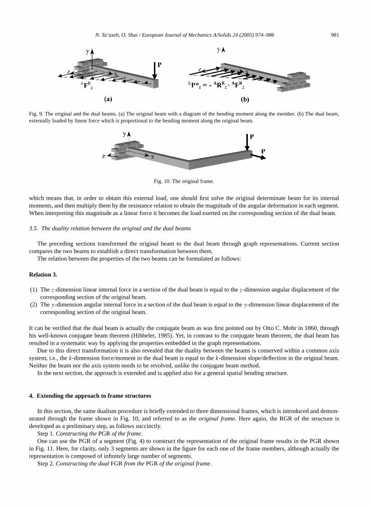
Fig. 9. The original and the dual beams. (a) The original beam with a diagram of the bending moment along the member. (b) The dexternally loaded by linear force which is proportional to the bending moment along the original beam.
Fig. 10. The original frame.
which means that, in order to obtain this external load, one should first solve the original determinate beam for itsmoments, and then multiply them by the resistance relation to obtain the magnitude of the angular deformation in eachWhen interpreting this magnitude as a linear force it becomes the load exerted on the corresponding section of the du
3.5. The duality relation between the original and the dual beams
The preceding sections transformed the original beam to the dual beam through graph representations. Currecompares the two beams to establish a direct transformation between them.
The relation between the properties of the two beams can be formulated as follows:
Relation 3.
(1) Thez-dimension linear internal force in a section of the dual beam is equal to thez-dimension angular displacement of tcorresponding section of the original beam.
(2) They-dimension angular internal force in a section of the dual beam is equal to they-dimension linear displacement of thcorresponding section of the original beam.
It can be verified that the dual beam is actually the conjugate beam as was first pointed out by Otto C. Mohr in 1860his well-known conjugate beam theorem (Hibbeler, 1985). Yet, in contrast to the conjugate beam theorem, the dualresulted in a systematic way by applying the properties embedded in the graph representations.
Due to this direct transformation it is also revealed that the duality between the beams is conserved within a comsystem, i.e., thek-dimension force/moment in the dual beam is equal to thek-dimension slope/deflection in the original beaNeither the beam nor the axis system needs to be revolved, unlike the conjugate beam method.
In the next section, the approach is extended and is applied also for a general spatial bending structure.
4. Extending the approach to frame structures
In this section, the same dualism procedure is briefly extended to three dimensional frames, which is introduced anstrated through the frame shown in Fig. 10, and referred to asthe original frame. Here again, the RGR of the structuredeveloped as a preliminary step, as follows succinctly.
Step 1.Constructing thePGRof the frame.One can use the PGR of a segment (Fig. 4) to construct the representation of the original frame results in the PG
in Fig. 11. Here, for clarity, only 3 segments are shown in the figure for each one of the frame members, although actrepresentation is composed of infinitely large number of segments.
Step 2.Constructing the dualFGRfrom thePGRof the original frame.
982 N. Ta’aseh, O. Shai / European Journal of Mechanics A/Solids 24 (2005) 974–986
ference
ow graph13, with
al frame
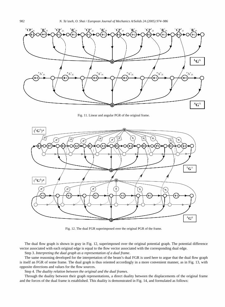
Fig. 11. Linear and angular PGR of the original frame.
Fig. 12. The dual FGR superimposed over the original PGR of the frame.
The dual flow graph is shown in gray in Fig. 12, superimposed over the original potential graph. The potential difvector associated with each original edge is equal to the flow vector associated with the corresponding dual edge.
Step 3.Interpreting the dual graph as a representation of a dual frame.The same reasoning developed for the interpretation of the beam’s dual FGR is used here to argue that the dual fl
is itself an FGR of some frame. The dual graph is thus oriented accordingly in a more convenient manner, as in Fig.opposite directions and values for the flow sources.
Step 4.The duality relation between the original and the dual frames.Through the duality between their graph representations, a direct duality between the displacements of the origin
and the forces of the dual frame is established. This duality is demonstrated in Fig. 14, and formulated as follows:

N. Ta’aseh, O. Shai / European Journal of Mechanics A/Solids 24 (2005) 974–986 983
he linear
nt of the
nt of the
d. Again,ed withthe
Fig. 13. The FGR of the dual frame.
Fig. 14. Flows in the dual frame as potentials in the original frame. (a) The internal moments in the dual frame are equal to (b) tdeflections of the original beam. (c) The internal linear forces in the dual frame are equal to (d) the slopes of the original frame.
Relation 4.
(1) The linear internal force vector in a section of the dual frame is equal in value to the vectorial angular displacemecorresponding section of the original frame.
(2) The angular internal force vector in a section of the dual frame is equal in value to the vectorial linear displacemecorresponding section in the original frame.
This result coincides with the conjugate frame method (Abdul-Shafi, 1985), an extension of the conjugate beam methonot only the duality resulted through a determinate procedure of graph theory, but it also voids the complication involvthe conjugate frame method, that is revolving the structure. Thek-dimension force/moment in the dual frame is equal to

984 N. Ta’aseh, O. Shai / European Journal of Mechanics A/Solids 24 (2005) 974–986
nlike theal and the
l structure.conjugate
related tothe lineara commonectively,
gular orelements
Table 2Duality between structural elements through the PGR-to-FGR duality
Original structuralelement
Original PGR (black) and the dual FGR(gray) superimposed
Dual structuralelement
Free end joint Constrained joint
Constrained joint Free end joint
Common joint Common joint
Mixed joint Mixed joint
k-dimension slope/deflection in the original frame. Neither the structure nor the axis system needs to be revolved, uconjugate frame method. Fig. 14, demonstrates the correspondence between different types of variables of the origindual frames.
4.1. Expanding the approach to a general frame/beam structure
The approach, which was demonstrated so far via a specific L-shaped frame, can be generalized to any skeletaTable 2 provides a set of conversion rules that can be used to transform between a general skeletal structure and its(dual) counterpart.
Generally, as illustrated in the first three rows of the table, each of the six linear and angular degrees of freedoman end joint of a segment has 3 alternative conditions: either it is free, constrained, or common to another segment. Inor angular PGR, these conditions are represented, respectively, as a free potential vertex, a zero potential vertex, orequipotential vertex. Through the dual angular or linear FGR it is deduced that the dual structural element is, respa constrained joint, a free joint, or a common joint. Note that the dual of an original linear or angular condition is an anlinear dual condition, respectively. On the basis of the three basic conditions, the dual of all other types of structuralcan be deduced, as demonstrated by the mixed joint example in the bottom of the table.

N. Ta’aseh, O. Shai / European Journal of Mechanics A/Solids 24 (2005) 974–986 985
e. Givingo, to theroach hasnd beams,between
95) enableight uponorems in
formations the dualwith thevior of twotematically
sity Press,
. Industry
, A. (Ed.),
nning B 6,
nipulators.
Design,
delphia,
ernational
5. Conclusions
The paper has shown a new perspective on conjugate theorems from the aspect of graph theory duality principlthis new perspective to the conjugate theorem was found to contribute not only to the engineering theory but alsunderstanding of the mathematical relations underlying the duality between graph representations. Till now, this appled to establishing of the duality relation between determinate trusses and linkages, duality between gear systems apillar systems and kinematical systems and other known (Waldron and Hunt, 1991) and new (Shai, 2001) relationsengineering systems. It should be noted that although known methods in structural mechanics (Shames and Dym, 19to perform analysis of beams and frames more efficiently than graph representations, the latter enable alternative insthe behavior of the systems. Moreover the graphs provide another view on the mathematical foundation underlying thestructural mechanics, as was demonstrated throughout the paper.
Understanding the discrete mathematical foundation underlying the conjugate theorems brought up a new transchannel, in which one represents the potentials of the original system (in the paper – displacements) and from it deriveengineering system, from which the information about its flows (forces) is obtained. Existing approaches correlatingpresented result rely on correspondences between the vector spaces spanned by the variables underlying the behasystems, or the same system. Nevertheless, employing graph-theoretical tools is what makes possible to establish systhe topologies of the new systems.
References
Abdul-Shafi, A., 1985. Conjugate frame for shear and flexure. J. Structural Engrg. 111 (3), 595–608.Andrews, G.C., 1971. The vector-network model – a topological approach to mechanics. Ph.D. thesis, University of Waterloo.Cha, P.D., Rosenberg, J.J., Dym, C.L., 2000. Fundamentals of Modeling and Analyzing Engineering Systems. Cambridge Univer
Cambridge.Davies, T., 1983. Mechanical networks – III, Wrenches on circuit screws. Mechanism and Machine Theory 18 (2), 107–112.Deo, N., 1974. Graph Theory with Applications to Engineering and Computer Science. Prentice-Hall, Englewood Cliffs, NJ.Dobrjanskyj, L., Freudenstein, F., 1967. Some application of graph theory to the structural analysis of mechanisms. ASME J. Engrg
Ser. B 89, 153–158.Duffy, J., 1996. Statics and Kinematics with Applications to Robotics. Cambridge University Press, Cambridge.Fenves, S.J., 1966. Structural analysis by networks, matrices and computers. J. Structural Div. ASCE 92, 199–221.Fenves, S.J., Branin, F.H., 1963. Network topological formulation of structural analysis. J. Structural Div. ASCE 89 (ST4), 483–514.Fenves, S.J., Logcher, R.D., Mauch, S.P., 1965. STRESS – a User’s Manual. MIT Press, Cambridge, MA.Finger, S., Rinderle, J.R., 2002. Transforming behavioural and physical representations of mechanical designs. In: Chakrabarti
Engineering Design Synthesis – Understanding, Approaches and Tools. Springer, Berlin, pp. 303–316.Freudenstein, F., Maki, E.R., 1979. Creation of mechanisms according to kinematic structure and function. J. Environmental and Pla
375–391.Girvin, S.M., 1996. Duality in perspective. Science 274, 524–525.Gosselin, F., Lallemand, J.-P., 2001. A new insight into the duality between serial and parallel non-redundant and redundant ma
Robotica 19, 365–370.Hibbeler, R.C., 1985. Structural Analysis. Macmillan, New York.Iri, M., Recski, A., 1982. What does duality really mean?. Int. J. Circuit Theory Appl. 8, 317–324.Kaveh, A., 1991. Graphs and Structures. Computers and Structures 40, 893–901.Kron, G., 1963. Diakoptics – A Piecewise Solution of Large-Scale Systems. Macdonald, London.Lorens, C.S., 1964. Flowgraphs for the Modeling and Analysis of Linear Systems. McGraw-Hill, New York.McGuire, W., Gallagher, R.H., 1979. Matrix Structural Analysis. Wiley, New York.McPhee, J.J., 1996. On the use of linear graph theory in multibody system dynamics. Nonlinear Dynamics 9, 73–90.Paynter, H.M., 1961. Analysis and Design of Engineering Systems. MIT Press, Cambridge.Pedoe, D., 1963. An Introduction to Projective Geometry. Pergamon Press, Oxford.Phillips, J., 1984. Freedom in Machinery. Cambridge University Press, Cambridge.Recski, A., 1989. Matroid Theory and its Applications in Electric Network Theory and in Statics. Springer, Berlin.Seshu, S., Reed, M.B., 1961. Linear Graphs and Electrical Network. Addison-Wesley, Reading, MA.Shai, O., 2001. The multidisciplinary combinatorial approach and its applications in engineering. J. AIEDAM – AI for Engineering
Analysis and Manufacturing 15 (2), 109–144.Shames, I.H., Dym, C.L., 1995. Energy and Finite Element Methods in Structural Mechanics. SI Unit Edition. Taylor & Francis, Phila
PA.Swamy, M.N.S., Thulasiraman, K., 1981. Graphs, Networks, and Algorithms. Wiley, New York.Ta’aseh, N., Shai, O., 2002. Derivation of methods and knowledge in structures by combinatorial representations. In: The Sixth Int
Conference on Computational Structures Technology, Prague, Czech Republic, 4–6 September.

986 N. Ta’aseh, O. Shai / European Journal of Mechanics A/Solids 24 (2005) 974–986
120 (2),
ichigan.
Tarnai, T., 1989. Duality between plane trusses and grillages. Int. J. Solids Structures 25 (12), 1395–1409.Tsai, L.W., Chen, D.Z., Lin, T.W., 1998. Dynamic analysis of geared robotic mechanisms using graph theory. ASME J. Mech. Design
240–244.Waldron, K.J., Hunt, K.H., 1991. Series-parallel dualities in actively coordinated mechanisms. Int. J. Robotics Res. 10 (5).Wang, K., Bjorke, O., 1991. The validity of mechanical networks. Systems Sci. 17 (4), 55–71.Ward, J.R., 1968. The Signal Flow Graph in Linear Systems Analysis. Prentice-Hall, Englewood Cliffs, NJ.Wilson, B.H., 1992. Model-building assistant: an automated-modeling tool for machine-tool drive trains, Ph.D. thesis, University of M