Embed Size (px)
DESCRIPTION
Â
Citation preview

JOURNALJOSHUA GRAF 587672
ARCHITECTURE STUDIO AIR

CONTENTS
Introduction
Part A: ConceptualisationA.1. Design Futuring
Urban Algae Pavilion - EcoLabStudio Table Cloth - Ball Nogues A.2. Design Computation
A.3. Composition to GenerativeA.4. Part A Conclusion
A.5. Learning outcomes Part A References
Part B: Conceptual Design B.1 Research - Recursion
Alisa Andrasek - Bloom Aranda Lasch - The Evening Line
B.2 - Case Study 1.0Process Explanation
L-systems MatrixSelection Criteria
Architectural Speculation B.3 - Case Study 2.0
Subdivided Columns - Micheal HansmeyerReverse Engineering
Case Study Creation ProcessReverse Engineering Results
Precedent Comparison B.4 - Technique: Development
Process ExplanationSubdivision Matrix 1Subdivision Matrix 2
Post Crit Design Development Selection Criteria
B.5 - Technique: PrototypesPrototyping Process
B.6 - Technique: ProposalDesign Application Proposal
B.7 - Learning Objectives and Outcomes Part B References
4....
6....
8.... 10.... 12....14....18.... 18.... 19....
20....22....24....26....
28....30....34....40....
42....46....48....50....52....
54....56....62....66....68....
70....
78....80....81....

3
Part C: Detailed DesignC.1 - Design Concept
Group Project Introduction Site Introduction Site Observations
Site AnalysisSite Response
Additional Site AnalysisAdditional Site Constraints
Form GenerationForm Refinement
Group ProposalC.2 - Tectonic Elements and Prototypes
Material TestingFinal Material Considerations
Consideration of FeedbackResponse to Crit Feedback
C.3 - Final Detail ModelFinal Model Build
Final Model Set UpFinal Tank Design
C.4 - Learning Objectives and OutcomesConclusion
Part C References
82....
84....86....88....94....96....100....102....104....118....124....
126....138....140....142....
144....148....152....
164....166....

4
My name is Joshua Graf, a final year Undergraduate Environments student, majoring in Architecture. Along side architecture I study a diploma in Japanese, and in my 3rd year I spent that year on exchange in Edinburgh, Scotland, focusing on architecture history and seeing a lot of it. I also got to spend Christmas in Poland with some long lost family and make my first ever snowman!
INTRODUCTION
A BIT ABOUT ME
WHY DESIGN?I derive a passion for design from 2 perspectives. The first is just part of me. I have always liked to draw, make paper mache, construct pyramids of lego, or help my dad build things. I suppose you could see this side of me as the desire to create both for the sake of aesthetics and out of enjoyment for the process.
A ABOUTBIT
ME
The second perspective is that I have come to realise that design can have a purpose and actually be useful, and so in turn I can have a purpose and be useful. And I believe it is this side of the 2 that is stronger in driving my passion for design because it itself grows as I slowly pick up and understand more about the world and how design can help and inform it.
How’d I get up there?!

5
DESIGN HISTORYThe core of my design work has formed during my time at university but my first attempt at it really began in high school. In my final year of school I opted to take a Visual Communication class over a calculus one because I wanted to practice these design skills. I designed a very aesthetically based Art Gallery and made a model to prove it. I then moved onto University and took my first studio Virtual Environments where I got stuck into rhino and its panelling tools and left the subject with a hanging, papercraft lantern emulating the skin patterns of a snake. My second studio that year left me designing a very theoretical tactile “judgement tower” which was my first time properly engaging with a site and immersing myself in developing and responding to ideas. Then came the Architecture Design Studio water where I learnt to familiarise myself with the work of Architectural Masters, designing a boathouse using the formal strategies of my chosen architect Herzog and De Meuron.

6
Part AC O N C E P T U A L I S AT I O N

7

8
URBAN ALGAE CANOPY - ecoLogicStudio
THE PROJECT
THEORY ENGAGED
large is the possibility of considering architecture almost as a literal organic structure. As portrayed by ecoLogicStudio, “it is now time to overcome the segregation between technology and nature typical of the mechanical age, to embrace a systemic understanding of architecture” (EcoLogicStudio, 2014). This “systemic understanding” is an attempt to frame architecture through a glass that acknowledges that what we choose to construct should not only serve people and their needs but should too be integrated into, and have integrated into it systems that can work to negate the destructive effects our societies unquestionably create for the environment we inhabit. The Urban Algae Canopy attempts to engage this theory of natural integration and give a tantalising example of how technology like that developed in “algaetecture” could be effectively assimilated into the general urban fabric.
The Urban Algae Canopy is designed by the team at ecoLogicStudio for the World Expo 2015 in Milan as part of the Future Food District Project. Whilst being a canopy, the structure involves a bio-digital system developed by the team over the past 6 years which runs a flow of algae, water, energy and CO2 through the structure which not only generates the equivalent oxygen of 4 hectares of woodland and up to 150kg of biomass per day but also responds to user presence via increasing the flows within the system to dynamically alter the available shade and its intensity. It is this union of nature and parametric design that drew me to this project.
The relevance of this project to society at
Image 1 - Urban Algae Canopy Render

9
A.1. DESIGN FUTURING
FUTURES IMAGINEDIt is not so radical an idea as ideas for adapting algae for various uses in architecture have been developed in the past (such as algae panels to generate electricity). However it is definitely very timely and very effective in getting people to properly imagine a future where organic life is intricately comwbined into the built environment. The qualities of a place like a forest could be established, with variable lighting and shade, generated oxygen and a response to visitors and beings within its presence.
Image 2 - System prototype currently be-ing showcased at the University of Milan. The prototype depicts the algae system and the shading reaction to visitors.
Image 2 - System prototype currently be-ing showcased at the University of Milan. The prototype depicts the algae system and the shading reaction to visitors.

10
TABLE CLOTH - Ball Nogues Architects
Image 1 - Top View of Table Cloth
Image 2,3,4 - Detail Views

11
The base of the design develops from Ball Nogue’s research into the reuse of temporary structures and installations. Instead of destroying or disposing of the installation after its purpose has been served, they have developed a manufacturing methodology they call “Cross Manufacturing” that constructively critiques the three R’s of sustainability (recycling, reuse and repurposing), processes that normally down-cycle material into less valuable states. Cross Manufacturing defined by Ball Nogues is “an integrated design and manufacturing strategy that harnesses digital computation and fabrication technologies to make architectural scaled installations that become collections of smaller scaled products” (Ball Nogues, 2010). In the context of this project, at the end of the installation period the ‘fabric’ was
As a symbolic gesture of sustainability and a reminder that the buildings we construct are impermanent, the installation envisages a less deterministic view of products, buildings and materials into the future. Table Cloth questions single-purpose or un-adaptable creations almost with a view that waste for the sake of ‘something we don’t want to use anymore’ is unacceptable.
THEORY ENGAGED
FUTURES IMAGINED
Table cloth by Ball Nogues is an architectural installation designed for a music school courtyard that creates a “fabric” from tables and stools collectively linked together. Each of these low, coffee-style tables and 3 legged stools are unique and are designed specifically for the installation but also to be used day to day. Table Cloth serves as an “integrated set piece, backdrop, and seating area for student musical performance and everyday social interaction” (Ball Nogues, 2010).
THE PROJECTbroken down into its ‘smaller scaled products’, i.e. tables and chairs, and distributed out to the local community. As such, in the one action the project is making a comment both on how we think about building and reusing architectural installations, and one-purpose-consumer products we manufacture.
Image 5 - View from behind installation
A.1. DESIGN FUTURING

12
Computing itself cannot design, we the autonomous must still provide the rules, algorithms and intent to make the computer generated relevant to real life. But as argued by Kalay (2004) computing as a form of untiring and exact calculation influences the design process by allowing us to create things our easily distracted and
often mistaken minds cannot. By utilizing contemporary programs and technologies, such as grasshopper, there is greater potential for geometrical and formal theoretical exploration via the program’s ability to flesh out visual form based upon the complex algorithms we have not had the ability nor time to comprehend. A great example of this exploration is shown through the studio Biothingy, whose projects such as Climath demonstrate an application of very complex and algorithmic based forms to enhance and inform the creation of a real space.
12
DESIGN COMPUTATION
Image 1: Climath by Biothingy
13
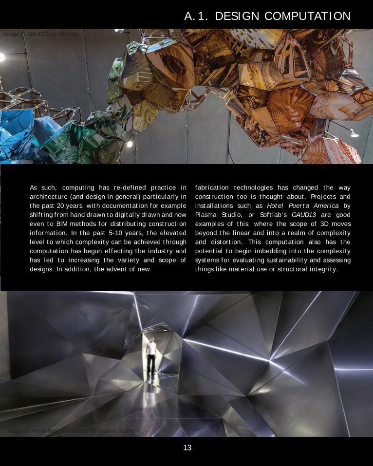
As such, computing has re-defined practice in architecture (and design in general) particularly in the past 20 years, with documentation for example shifting from hand drawn to digitally drawn and now even to BIM methods for distributing construction information. In the past 5-10 years, the elevated level to which complexity can be achieved through computation has begun effecting the industry and has led to increasing the variety and scope of designs. In addition, the advent of new
fabrication technologies has changed the way construction too is thought about. Projects and installations such as Hotel Puerta America by Plasma Studio, or Softlab’s GAUD13 are good examples of this, where the scope of 3D moves beyond the linear and into a realm of complexity and distortion. This computation also has the potential to begin imbedding into the complexity systems for evaluating sustainability and assessing things like material use or structural integrity.
13
Image 3: Hotel Puerta America by Plasma Studio
Image 2: GAUD13 by Softlabs
A.1. DESIGN COMPUTATION

14
COMPOSITION TO GENERATIONThe past 15 years have seen a deep change in architectural practice and thinking occur, the major influences of which have been sustainability and technological advance (Peters, 2013). The combination of these two factors is interesting because it simultaneously represents a time where more is being demanded of architecture, particularly in terms of performativity, and design methods and opportunities are increasing and evolving at an unprecedented rate; i.e. stricter conditions but greater ability. To address this shift, one of the fundamental changes that has occurred is the shift from compositional to generative design. The main reason this is important is that whilst compositional design is primarily concerned with the organisation of form, the move into generative architecture presents a system where formation precedes form, where emphasis is on designing the design’s logic or process over the design’s form (Leach, 2009). The benefit to this model of thinking is at the current rate, form (in terms of architectural requirement, technology, etc.) is quickly outdated, but designing a process that is able to adapt to what is relevant means generated form can always be relevant and push our boundaries.
ALGORITHMIC THINKINGA large part of generative design is made possible through algorithmic thinking. Algorithmic thinking is in a way a form of specific problem solving whereby solutions are arrived at via a process of functional decomposition, parameterization, and repetition, in essence breaking down a problem into its smaller/smallest components and devising a set of steps to arrive at the solution (Cooper et al. 2000). This thought process lends itself strongly to generative design because when our design problems are broken down into a simple series of steps, a computer’s tireless and precise processes can be applied to the situation to extrapolate those simple steps beyond the capabilities of the normal human mind. A good example of this thinking in practice is the ‘Rules of Six’ installation by Aranda/Lasch where the rules of a snowflake were broken down, formed into steps, and replied recursively to a create wall piece for the Museum of Modern Art in New York.
Image 1: Snowflake patterns generated through algorithm

15
A.3.COMPOSITION TO GENERATION
Image 2: Final installation at the Modern Museum of Art, New York

16
Image 1: Aviva stadium shutter performative design process: (1) Rotation Angles defined (2) Venting provision compared to requirements (3) Wind blown rain check (4) Model assess aesthetically
(1)
(2)
(3)
(4)

17
As with anything however, despite the immense benefits generative design provides us with it is also important to be aware of a methods limitations. One such limitation is how the computational potential and flexibility is limited by the algorithmic components available to the program or language. This can be seen for example in how before plug-ins such as ‘Anemone’ or ‘Hoopsnake’ programs such as grasshopper were restricted in how they could approach recursion. Of course, there are ways around it, and as technology improves a lot of these issues become more and more negligible, but the restriction still exists. In addition, another concern embedded within the last issue is addressing the misconception that parametrics reduce design complexity (Dino, 2012). Whilst algorithmic thinking and parametric modelling provide fantastic tools for addressing complex issues and designs, the complexity of the issue still remains. The importance of the correction of this misconception is that people commissioning a building, or even a designer who holds this misconception, may wrongly believe that dealing with such a design is ‘easy’ and underestimate expertise and effort implementation of such programs require.
L IMITATIONSPARAMETRIC MODELLINGParametric modelling is then the engagement of the scripts developed out of the algorithmic thinking method applied to modelling form. The key element of this type of design is that the building, for example, can be first thought about in terms of its important components, with these then used as the building blocks of a design. These parameters can then be varied to easily test and experiment the different potentials for the building. The Khan Shatyr Entertainment Centre by Foster + Partners for example utilised a form-finding algorithm to quickly generate a variety of forms for its cable-net structure in order to assess alternatives (Peters, 2013). The true potential in parametric modelling however lies in the ability of it to inherently incorporate performative qualities. For example, if a performative logic were to be written into a script to assess the efficiency of structural members or to minimize sun load, the resulting forms are automatically optimised to such requirements. This method is effectively shown in the Aviva Stadium by Populous, where a design loop was implemented in the model that proposed rotation values, recorded ventilation areas and windblown gaps, and a 3D representation produced. This data was then able to be analysed to determine which configuration was most efficient in dealing with wind load to inform decision making (Hudson et al., 2011).
A.3.COMPOSITION TO GENERATION
Image 2: Aviva Stadium, Dublin
17

18
A.4. CONCLUSION A.5. LEARNING OUTCOMES
At the conclusion of Part A I definitely feel like I have a better understanding of digital computation in architecture and the direction it is currently leading us. At the beginning of semester I knew a little about grasshopper and algorithmic thinking, particularly via messages that had been passed down to me by friends and previous students of this subject. Some were really positive and saw digital computation and generative design as a fantastic tool. Others were sceptical, and saw generative processes taking the ‘design’ out of peoples work. Now that I have engaged with this subject I have begun to develop hope for where digital computation can lead us into the future. For me personally, environmental impact and response is a key driver for my goals as a designer, and I believe that the performative qualities of parametric and generative design in digital computation are slowly (and sometimes rapidly) creating new and interesting solutions to these issues, as society too slowly understands better and identifies where we need to address these issues. In addition, I find the process of algorithmic thinking quite an enjoyable task to engage with, with both the unexpected and interesting results, and the struggles sorting through the code resulting in what I feel to be a worthwhile challenge.
Digital computation in design is potentially the most important element of current architectural theory that needs to be engaged with. The countless number of unexplored and unimagined solutions contained within current technology, in conjunction with new technology likely to be created into the future presents a strong case for continued engagement within the discipline. When these computational processes are coupled with thinking about design futuring, a very positive or hopeful outlook is generated where digital experimentation and simulation can help foster thought on these issues of sustainability, in regards to materiality, structure, passive design, and other forms of performative system inclusion. As such, the design approach I intended to follow is one that engages with cutting edge applications of digital computational tools, with the overall intent then being to question and further the discussion on both the use of these tools and our potential futures. An approach such as this is significant purely for its use in testing and pushing boundaries. If a project is able to work at and push the extents to which we understand how we design and the limits of technology, it ultimately benefits both the people who are working within these boundaries, and people on the receiving end of design, particularly if these new perspectives or designs are able to flow on to affect how society thinks about other issues.
19
PART A REFERENCES
Cooper, Stephen, Wanda Dann, and Randy Pausch. “Developing algorithmic thinking with Alice.” The Proceedings of ISECON 2000. Vol. 17. 2000.
Leach, N.(2009) ‘Digital Morphogenesis’, Architectural Design, 79:1;32-7
Peters, Brady. (2013) ‘Computation Works: The Building of Algorithmic Thought’, Architectural Design, 83, 2, pp. 08-15
Image 1 < https://farm5.staticflickr.com/4027/4479248423_16d858fb3c_b.jpg>
Image 2 < https://farm4.staticflickr.com/3263/3192008252_0c5007ca04_z.jpg?zz=1>
Dino, İpek GÜRSEL. “Creative design exploration by parametric generative systems in architecture.” Metu Jfa 1 (2012): 207.
Hudson, Roly, Paul Shepherd, and David Hines. “Aviva Stadium: A case study in integrated parametric design.” International Journal of Architectural Computing 9.2 (2011): 187-204.
Image 1, Hudson, Roly, Paul Shepherd, and David Hines. “Aviva Stadium: A case study in integrated parametric design.” International Journal of Architectural Computing 9.2 (2011): pg 198
Image 2 < http://www.bancrete.com/wp-content/uploads/2011/12/Aviva-Stadium-2.jpg>
Kalay, Yehuda E. (2004). Architecture’s New Media: Principles, Theories, and Methods of Computer-Aided Design (Cam-bridge, MA: MIT Press), pp. 5-25 Image 1: http://plethora-project.com/completeworks/wp-content/uploads/2012/03/20c-hires-mod.jpg Image 2: http://softlabnyc.com/wp-content/uploads/2015/02/guad_2013_17.jpg Image 3: http://www.plasmastudio.com/work/images/architecture/Hotel_Puerta_America/PS_HPA_PHOT_BILT_02.jpg
Ball Nogues. 2010. ‘Table Cloth for courtyard at Schoenberg Hall’ < http://www.ball-nogues.com/#project-87> [accessed 6:15pm 12/03/2015]
Image 1 < http://www.ball-nogues.com/sites/default/files/imagecache/big_image/mayoralPhoto_ball_tableclothSchoen-bergHall_highRes-8_2.jpg> Image 2 < http://www.ball-nogues.com/sites/default/files/imagecache/big_image/DSC04266.JPG> Image 3 < http://www.ball-nogues.com/sites/default/files/imagecache/big_image/mayoralPhoto_ball_tableclothSchoen-bergHall_highRes-18_2.jpg>
Image 4 < http://www.ball-nogues.com/sites/default/files/imagecache/big_image/mayoralPhoto_ball_tableclothSchoen-bergHall_highRes-13_2.jpg>
Image 5 < http://www.ball-nogues.com/sites/default/files/imagecache/big_image/mayoralPhoto_ball_tableclothSchoen-bergHall_highRes-4_1.jpg>
ecoLogicStudio. 2014. ‘Algae Canopy’. ecoLogicStudio < http://www.ecologicstudio.com/v2/project.php?idcat=3&idsubcat=59&idproj=137 > [accessed 3:19pm 12/03/2015]
Testado.J. 2014. ‘The Urban Algae Canopy shows the power of “algaetecture” for Milan Expo 2015’. Archinect News. < http://archinect.com/news/article/98218917/the-urban-algae-canopy-shows-the-power-of-algaetecture-for-milan-ex-po-2015> [accessed 3:35pm 12/03/2015]
Image 1 < http://www.ecologicstudio.com/v2/medias/imgs/projects/1746-P-137-20141020073418.jpg>
Image 2 < http://cdn.archinect.net/images/514x/wv/wvemft8agvhqy7bd.jpg>
pg 8-9 - A.1. Design Futuring - Urban Algae Canopy
pg 10-11 - A.1. Design Futuring - Tablecloth
pg 12-13 - A.2. Design Computation
pg 14-15 - A.3. Composition to Generative
pg 16-17 - A.3. Composition to Generative

20
PART B C R I T E R I A D E S I G N

21

22
RECURSION
RECURSION is, in its simplest form, the PROCESS of continuously repeating or LOOPING a basic operation through an ALGORITHM over and over to arrive at a solution that would otherwise be highly labour intensive. This operation can be as simple as folding a surface at a certain point, but can still result in very COMPLEX, DETAILED, and INTERESTING forms and configurations, depending on the extent to which the algorithm is allowed to loop.

23
B.1 RESEARCH FIELD
so that along this new branch another branch is created at this proportion and so on (3). Following this process means before long quite a complex network of branches are created (3). An important thing to note in this process however, is that as the creator or controller of this algorithm only a basic amount of effort is required in setting up the definition, and the more labour intense process of exactly sketching out the form is left to computation. This inherently situates recursive form-finding as a generative process.
Recursion is not strictly a form finding technique but when applied to geometry it can result in some very unique and dynamic applications. One very famous example of recursion is the L-system, a process that can be seen to replicate the manner in which branches on a tree split off and form. Here the base theory (or algorithm) is that starting with an initial branch, at some point along the branch another branch is created at some proportion to the inital branch (1). This algorithm is then looped
X
0.7X 0.7X
0.7(0.7X)
0.7(0.7X) 0.7(
0.7X
)
0.7(0.7X)
(1) (2) (3)

24
RECURSION EXAMPLE - BLOOMcreated. Interestingly, the project was opened up to the public as “Bloom: The Game”, allowing people to get a hold of these components and generate their own designs, much like a Lego set. Here we not only see an engagement with community but also the design breaking out of the digital realm, where designs are tested by adjusting parameters and extents of recursion, and into the control of an individual user, which provides a very organic, human means by which the initial definition can be explored. Whilst in this perspective it can be said that the generative process is handed back over to labour, it is still a relevant point to consider as engaging the process with an intelligent mind allows solutions to be found in a very different way to the exact way in which an algorithm would.
A real world application of L-system recursive geometry is in the project ‘Bloom’ by Alisa Andrasek. The beauty in this project’s approach to adapting a recursive definition is in the way it has maintained the element of simplicity to generate complexity. The adaptable installation relies on a single component mass produced, which contains within it 3 connection points that can slot multiple of these components together. In the definition, the distance and angle of the slots from the central point of the component can be manipulated, with these variations affecting the overall structure.
From this premise alone, depending on which slots are chosen and the order these are configured, almost unlimited variations and designs can be
Image 1: Bloom

25
B.1 RESEARCH FIELD
Image 2: Bloom
Image 3: Bloom

26
RECURSION EXAMPLE - THE EVENING LINE
(1) (2) (3)
The fact that recursion relies on the repetition of base algorithms also makes recursive geometry susceptible to fractal formations. This is meant in the sense that many forms can be created through a recursive application of an algorithm to create a geometry that at many different scales contains similar, or indeed exactly the same proportioned elements and shapes. And, while this may initially seem like a trivial bi-product it is in fact a rather unique quality of recursive definitions.
For example, a pyramid (1) can be truncated using scaled versions of itself (2). Those triangles used to initially truncate can then be scaled and truncate themselves again (3), beginning the series of an infinite potential of fractals. As such, intersecting and orienting these scaled elements can lead to rather unique distortions of forms and methods for creating ornamentation, all of this still being framed within a generative model.
Image 1: Evening Line

27
A fantastic example of this in practice is the project ‘The Evening Line’ by Aranda Lasch. The design is based upon a fractal distribution of these scaled truncated tetrahedrons, which are then laced with unique patterns on each surface. The result is a project that is visibly extremely intricate on multiple scales, drawing you in to appreciate smaller details, whilst also maintaining an appreciable relation of formal proportions between its various elements. The project is a good example of combining two simple operations looped in an algorithm to generate an interesting complex form that still contains structure and formal relationships.
B.1 RESEARCH FIELD
Image 2: Evening Line

28
PROCESS EXPLANATIONTo begin my exploration of recursion in Grasshopper, I focused on testing and pushing the limits of the L-system. In this experimentation process, I not only experimented with the parameters (which I discovered can create an almost infinite amount of arrangements in a recursive model, albeit certain patterns arising), but looked for new methods of
SPECIES 1
SPECIES 2
SPECIES 3
The first species is examples taken from the initial L-system definition. To reiterate the process, the logic relied upon repositioning 3 scaled versions of an initial line on a point at the end of this initial line and then applying a rotation to these new lines around that point. Both the length of the new line, and its rotation in XYZ could be altered.
Expanding on from the initial, species 2 uses the same process but introduces more lines as the initial. In these examples I have positioned 6 lines outwards from the central point, each of these lines independently acting as the starting line. Again, its parameters were line length and XYZ rotation.
In species 3 I introduced surfaces to the L system. In this logic, only 2 lines were replicated, but between these new lines and the old line a web-like surface was created, the web’s curve based upon an interpolated curve between the end points. Here, both the rotation and the line length were seperated for both lines, giving flexibility in the surface’s form.
application to develop greater diversity and potential. As a result, I went through 6 phases or ‘Species’ of L-system definitions and logic in exploring the L-system, each species developing on from an element of the previous and containing slightly altered parameters.

29
B.2 CASE STUDY 1.0
SPECIES 4Continuing along the line of surfaces, instead of just creating surfaces between lines, I also tried applying/positioning forms directly onto the lines, using the base line-structures as references points. Initially I just tried using spheres, with the parameters being their radius and the line’s XYZ rotation, but I then also tried creating 2 point boxes between start and end points, resulting in some rather intriguing forms.
SPECIES 5In species 5, instead of repeating and positioning lines, I re-imagined it as repeating and positioning pipes. This added the variability of scaling both length and thickness with consecutive loops, whilst also adding to the three-dimensionality and tangibility of the forms. When I then also tried to apply the logic to a triangular extrusion, it resulted in a rather unexpected outcome.
SPECIES 6The final species furthered the application of changing the form of the initial object to repeat, with focus moving to cubes and spheres. I also incorporated an aspect of species 2, where I set the objects to be scaled and repositioned in 6 different directions. Here, whilst controlling the level scaling was an element, often the most interesting forms came with the extent of scaling, or toggling what was recorded.

30
L-SYSTEMS MATRIX
S1 S2
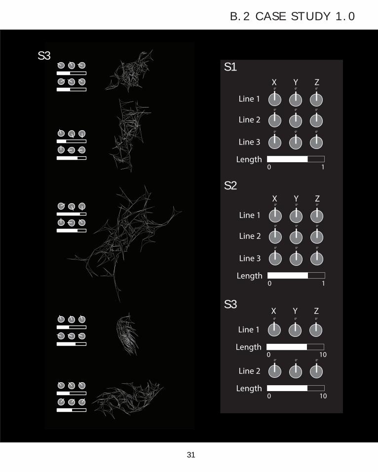
31
B.2 CASE STUDY 1.0
ZX
Line 1
Line 2
Line 3
Length
Y
ZX Y
0 1
ZX
Line 1
Line 2
Line 3
Length
Y
0 1
Line 1
Length0 10
Line 2
Length0 10
0° 0° 0°
0° 0° 0°
0° 0° 0°
0° 0° 0°
0° 0° 0°
0° 0° 0°
0° 0° 0°
0° 0° 0°
S1
S2
S3
S3

32
L-SYSTEMS MATRIX
2 POINT BOX
2 POINT BOXON TRIANGULAR
EXTRUSION
S4 S5

33
B.2 CASE STUDY 1.0
ZX Y
ZX
Line 1
Line 2
Line 3
Length
Y
0 1Radius
0 1
Line 1
Length0
0° 0° 0°
0° 0° 0°
0° 0° 0°
0° 0° 0°
0° 0° 0°
10
Line 2
Length0 10
Scale Factor 0 1
Loops0 10
S4
S5
S6
S6

34
SELECTION CRITERIATo analyse the results of this process then, a selection criteria had to be developed in order to determine some iterations of ‘best fit’. To inform this criteria, I looked towards the Air Design Brief to determine if any qualities of my iterations were in some way applicable to the brief and its site, with the hope that some of these qualities may spark further interest and potential to follow in the design process.
The brief, over the course of the semester, had been honed down to developing a project for the Food Forest, an initiative co-ordinated at CERES along Merri Creek. The Food Forest is planned to be a self-sustaining ecosystem that consistently
Permeabil ity - consideration of this trait focuses on the potential for movement within the structure as a result of the relationships between its various elements. Both potential high (fostering insect and water penetration) and low (controlling water catchment) permeabilities are considered, with the focus being on interesting potential.
Detail - again concerning context, natural elements can almost always been seen to be organised assortments of smaller elements (like leaves and twigs). To be relevant to space then, the iteration will be assessed for its degree of detail and accumulation of forms. Recursion is inherently suited to these configurations so understandable or beautiful forms will be favoured.
Material ity - more aptly thought of as ‘potential materiality’, this trait conjectures on what materials would be used to begin to contemplate the structure. Particularly as the Food Forest is a place of food production and sustainability, careful considerations of materials is important to their feasibility.
Integration - here the consideration is given to how an iteration’s form could be combined with other elements of the Food Forest. Again, thinking about this structure in context, a forest intimately weaves its elements together, with everything discarding selfishness and working with the system to enhance it. As such, so too should the iteration comply with this logic.
produces fruit, vegetables, and other organic produce, much like a real-life forest, to set itself up as an example for sustainable food growing. As such, a large range of structures needed in setting up the forest exist, each being able to be enhanced through the parametric model. Some of these needs include water catchment, bee inhabitance, sacraficial growing lattices, seating and shading, and so on.
Thus, to initially engage with the link between these needs of the Food Forest and potential form, I decided on the following 4 traits to focus my selection criteria on:
In using these factors as my selection criteria, I was intending to further my scope on application of recursive forms for the Food Forest. I decided then that the examples I highlighted did not have
to balance all of the criteria factors, but instead could be strong examples of each so as to imagine ways in which more successful iterations could be combined to compliment eachother.

35
B.2 CASE STUDY 1.0
complex sort of detail, as the smaller elements work to abstract the form of the larger elements, creating a sort of visual interest.
I think it important to re-iterate for this iteration that the emphasis is really on the proportion of elements rather than its form. This specfic relationship between scaled elements alludes to its potential for integrating objects and materials of differing characters and sizes into a cohesive structure. The form is very adjustable around this set of proportions.
In this iteration the variations in scaled elements most importantly reflect well the various factors of the criteria. The differing levels of scale offer potential for a materiality integration response, with differ layers of scale correlating to a different material or point of connection to another element of the forest. Larger elements, for example, could act as structural elements and smaller elements could be attachment points for vines or vegetables as they grow. It also has potential to be intergrated with a mesh or tarp-like covering to foster mesh growth or contain growth. It also complies with a

36
This example is a fantastic example of integration potential because it depicts a scenario where elements, in this case spheres, can be dispersed via a connected structure. Application of this could include adhering pots or containers at the points represented by spheres to create a structure that effectively distributes plants (both for space means or layering specific plants for sunlight needs) whilst maintaining access to rain water, for example. This also resonates with ideas of permeability, with the structure allowing for the catching of particles,
such as water or dirt, with a high percentage but interspersed through out the structure. The spread points in a dispersed yet dense way would also suggest a permeability and accessibility for bees to engage with the structure if the example of plants were used again at those points.
The advantage of this iteration over the other similar ones in species 4, is that the connecting rods being of quite constrasting sizes lends to its potential for covering area effectively.
SELECTION CRITERIA

37
Permeability and materiality based upon this iteration’s form and surfaces are the key aspects to this iteration being highlighted. The form created here proposes a very directional permeability, whereby objects caught or grown on the structure would tend to follow the pathways through its structure. This role would then be very respondant to its materiality, as a smoother continous surface could be used to promote things like water catchment, while a mesh-like material could serve
as the base for lentil growth. Integration potential also lies within the iteration, the tweaking of its permeability potenitally being able to cater for both catchment and funneling of water and gentle watering of an underlying vegetable bed.
Also, from a materiality perspective, the fluid tendencies of this form could promote an efficiency of material use or strength through its regularity.
B.2 CASE STUDY 1.0

38
Above all in this iteration, its key reason for being highlighted is the way it creates detail. The whole form is consisted of tiny little boxes that themselves draw in attention and give an appreciation of the structure’s building blocks. More impressively though, these simple little blocks in their overall composition create very subtle patterns across the form’s surface, a pattern that repeats in scale according to the recursive definition. This subtle complexity is a quality of the form that makes it that much more interesting as an object to observe and engage with. If these qualities could be
combined to give surfaces an extra element of depth to their form, it could create structures that feel much more relevant and native to the composition of a forest, and further the desire for human interaction in the space.
The form too can be further extrapolated to imagine permeability uses, by deleting blocks to create interesting ways in which water or bees could eneter into the form, as could materiality enhance the pattern’s effects via things transparency.
SELECTION CRITERIA

39
This is one of the few iterations that really has something to contribute to all the selection factors in an interesting way. Permeability is possible in interesting ways in this configuration of boxes if the spaces created between the boxes are considered and used as paths through the form. So too can ‘pathways’ be formed if intersecting boxes are joined and allowed to be continous. The varying pathways lead to potential for encouraging different process in each path. This can be added to with materiality, with differing levels of
transparency, surface roughness, or perforation affecting how these processes could take place. This could also be used to enhance integration by linking or connecting the services of these various processes with other elements of the forest. Finally, detail is also apparent in its form with the complex arrangements of differently shaped and scaled boxes mismatching to create a shape. If combined again with materiality, these strange interactions could be emphasised to further interest in its form.
B.2 CASE STUDY 1.0

40
ARCHITECTURAL SPECULATIONHaving completed this initial exploration of recursive L-system logic in grasshopper, it is possible to begin to see how these techniques could be applied to assist the architectural process and imagine architectural form.
On a small scale, like discussed above for the Food Forest installation, the application of L-systems give rise to the possibility of changing levels of tangibility in a construction as the differing scales of elements can evoke differing responses. For example, in the first of my highlighted iterations the presence of different scales of tubes could respond to specific purposes (such as structural for large, vine lattice for small), creating a structure that can scale to facilitate multiple functions. This tangibility is also created through this application of complexity of scale, with various perspectives or interactions only being available from specific positions (e.g. an overall form can be appreciated from afar, but smaller elements must be conceived from closer inspection). The L-system logic as form finding is also quite useful on the small scale particularly, because the relatively low load requirements of structure at this scale allow L-system forms to be translated in a very literal way.
When projected onto a larger scale of construction however, an obvious constraint of L-system application is the appropriation of structural stability into its form, particularly when the forms become very dense and complex and more difficult to conceive. It is not feasible, for example, for a building to be held up by the thin little tendrils that may evolve from a centrally contrived definition, like those visibile in my above species 2. This does not limit its application however. Instead, the particularly relevent use of L-system form finding, is just that, application as a form finding technique. Often the L-system seems to create redundently impossible forms and scales, but these impossible elements can be replaced with relevant structure, forms, or products to make the space useable and real. This allows the L-system forms to maintain their pattern and logic in production, creating a potentially greater intrigue and interest when present in a space without resorting to L-systems as just a superficial aesthetic decoration. For example, an archway or atrium that bases its structure and form around the initial simpler lines, and then makes the sections of very complex linework lighting products, or surface details.

41
B.2 CASE STUDY 1.0Over archingly however, the major concern when trying to speculate about incorporating or using L-systems in a design, or indeed any recursive geometry, is how to deal with the complexity generated from this model of form making. Often, the most interesting or potent aspects of a form derived from recursion are the unexpected patterns and deeply detailed qualities that arise from the process. So too can less intense versions of L-systems be used to great effect, such as the tree-like columns used in the Stuttgart Airport, but often it is those projects that properly capture the extent of complexity possible in recursion, like the Digital Grotesque works by Micheal Hansmeyer, that really stand out.
Image 1: Stuttgart Airport
Image 2: Digital Grotesque
42
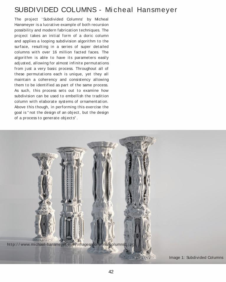
SUBDIVIDED COLUMNS - Micheal HansmeyerThe project ‘Subdivided Columns’ by Micheal Hansmeyer is a lucrative example of both recursion possibility and modern fabrication techniques. The project takes an initial form of a doric column and applies a looping subdivision algorithm to the surface, resulting in a series of super detailed columns with over 16 million facted faces. The algorithm is able to have its parameters easily adjusted, allowing for almost infinite permutations from just a very basic process. Throughout all of these permutations each is unique, yet they all maintain a coherency and consistency allowing them to be identified as part of the same process. As such, this process sets out to examine how subdivision can be used to embellish the tradition column with elaborate systems of ornamentation. Above this though, in performing this exercise the goal is “not the design of an object, but the design of a process to generate objects”.
http://www.michael-hansmeyer.com/images/columns/columns1.jpg
Image 1: Subdivided Columns

43
B.3 CASE STUDY 2.0The column was then fabricated 2.7 metres high, out of 1mm layers of laser cut paper. To do this, the digital model was intersected at 1mm intervals all the way up the model, the cross sections then trimmed of any interior holes or intersecting surfaces, and the outside shape joined into a continuous polyline. Then, to reduce weight and provide a manner for exactly stacking these slices, interior offsets were introduced before exporting and being cut on the laser cutter. The total construction took 4 people and 300 hours of labour to produce, all for just one column that should but a few minutes to produce in digital space. The result however, is a very impressively detailed object that maintains much of the facets and curvatures from the digital model and is even able to support a surprisingly large amount of load.
Image 1: Subdivided Columns
Image 2: Subdivided Columns
Image 3: Subdivided Columns

44
SUBDIVIDED COLUMNS - Micheal HansmeyerWhat is interesting about the columns is both the extent to which the excruciating detail exists, but also the process that derives it almost infinitely. Realistically with this process the only thing limiting it from looping continuously is the computational capacity of the computer running it, which is without a doubt one of the main concerns when producing work like this. Now, the project tends to explore the potential of designing objects from the confines of an algorithm, which in itself is a very compelling idea. In basic terms this notion means that the effort in design can be put into creating systems that are easily adapted and updated as trends and needs change, which then go on to physically draw out the form of the object
required. Where this idea is currently falling short is the translation from this digital state to tangible form. As demonstarted by the process above, currently this translation is intensely labourious and not without its imperfections. The use of 1mm paper really brings up the resolution at the scale produced to maintain much of the digital froms characteristics, but the resolution is still very much apparent. 3D printers are still not at the stage to bring this resolution down either, and to manually produce this from intructions seems otherwise impossible and ineffective either way. As such, the realistic potential lies in develop methods to further the ease of this translation from complex form into physcial form.
http://www.michael-hansmeyer.com/images/columns/columns3.jpg
Image 1: Subdivided Columns

45
B.3 CASE STUDY 2.0
http://www.michael-hansmeyer.com/images/columns/fabricated_columns5.jpghttp://www.michael-hansmeyer.com/images/columns/columns3.jpg
Image 2: Subdivided Columns

46
REVERSE ENGINEERINGThe initial problem with reverse engineering this project is that it was not done so in grasshopper. Instead it was written in code, like python, which in the realm of this is benefitial as it only has to render the final iteration, unlike the step by step process employed by Grasshopper and Anenome. The project too, is essentially a series of permutations of the doric column created through affecting parameters of the algorithm, which doesn’t give me a form to strive for in recreation. Instead I attempted to recreate a subdivision algorithm to develop a similar level of complexity on a surface.
As such, to test this I decided on developing a basic triangular pyramid instead of the doric column. The reasoning for this was in order to begin to comtemplate the surface in grasshopper, the surface of the column would have to had been simplified into a basic form of triangles anyway, so to make the computational process easier and to be able to further test the extents of the algorithm (without it crashing) I substituted it for the pyramid in the reverse engineering stage.

47
B.3 CASE STUDY 2.0

48
CASE STUDY CREATION PROCESS
The final method of attempting to recreate the Hansmeyer algorithm came back down to a very simple logic. In essense, to begin, a basic triangular surface is taken (1) and subvided into a number of sections (2), in this case three. This is most easily done by dividing to a point, which is very easily controlled by obtaining the midpoint of the surface. This point is then moved outward from the surface (3), with the subdivided section moving up with it to create a new set of surfaces. It is this movement or ‘folding’ as Hansmeyer refers to it that is the key to making this subdivision algorithm work. Without the movement, the surface can be infinitely subdivided but it will maintain its form. The folds are what allow the form to morph and develop. After this, the process is repeated on the new surface (4), completing the loop.
Applying this logic in grasshopper took alot of trial and error, particularly in finding the right component or method to perform the task I wanted.
(1) (2)
(3) (4)
Things like 2 surface normals being provided when trying to find a face normal vector to move out on were confusing, and required a developed understanding of the how the program dealth with parameters was important.
Another problem I encountered was being able to construct an algorithm that was able to loop without breaking. It required me to realise that in a loop you are applying exactly the same definition over and over, meaning that if the output of the initial algorithm is unable to then be understood by the algorithm when re-inserted at the beginning, it will break. An easy example is that if an algorithm is set up to deal with an initial square, but the re-inserted out put is a triangle, the parameters will not be fulfilled properly by the triangle and it could crash the algorithm. Sometimes this leads to weird and wonderful outbursts of confused and extreme geometry, but all of it I found to be unintelligible.

49
B.3 CASE STUDY 2.0

50
REVERSE ENGINEERING RESULTS
Having developed the recursive algorithm on the base triangle, I then applied it to the simplified version of the doric column to provide a grounds for comparison. To make the column I had to first split the column up into a number of sections. This was because when the definition, with even just one loop, was applied to the whole column at once it Wwould cause my computer to run out of memory and abandon the process. As such, breaking it down into a bunch of smaller sections allowed me to amp
up the the algorithm to run 3 loops across the whole form to begin to see how the recursion began to affect the surface. You can see in the close up that even 3 loops begins to develop a surface that is very complex, where shapes visibly beginning to intersect, the scale drops rapidly, and the form slowly acquires additonal mass. It is also possible to see how the column maintains some of its qualities, such as the basic head and base, and the long lines of the column shaft.
51
B.3 CASE STUDY 2.0

52
PRECEDENT COMPARISON
Image 1: Subdivided Columns
Image 2: Subdivided Columns
Image 3: Subdivided Columns

53
B.3 CASE STUDY 2.0When compared to some of the original Hansmeyer permutations, its first very obvious that the outcome of my algorithm is distinctly different, potentially not even the same. However, on closer inspection there are certain qualities between them that is comparable. The first is a their levels of complexity on the surface. In his algorithms Hansmeyer loops the definition up to 16 times, so inevitably they are smaller and more intricate. Having said that, in the comparison image of the surface close ups, it is possible to see that even with 3 loops a very complicated layering of forms is beginning to take place with the re-created definition. Another is the way they begin to distort the surface. The image comparing the capitals of the columns shows how in both models the inital form is recognisable but still in some way new and alien. I imagine that with
more experimentation with the definition, greater variations in how the defintion can affect the form is possible as well. A very distinct difference between the two projects though, is the differentiation in pattern. The image to the left comparing the shafts of the column clearly shows that whilst my definition produces a rather predictable assortment of forms along the surface, the Hansmeyer algorithms depict a greater differentiation of this pattern and form. This may be due to the greater flexibility that coding provides to the forms, but is also likely to be due to the limited way in which my algorithm creates new forms. Having said this though, generally I feel the algorithm works to an extent that it can create, at least in a similar fashion, a highly complex surface that evokes some senses of wanting to look closer.
Image 1: Subdivided Columns
Image 2: Subdivided Columns
Image 3: Subdivided Columns

54
DESIGN EXPERIMENTATION: PROCESS EXPLANATIONIn developing this process then, more so than the previous technique, I took a very methodical approach to breaking down the algorithm and identifying how different elements of the process informed the resulting outcomes, as set out below.
To begin with, I recorded in iterations the development of the base definition on the basic pyramid as loops were incrementally increased. In doing so, it was possible to notice how certain concentration points developed on the surfaces, where the surfaces began to increase in number and decrease in size. These points seemed to be controlled by where the initial definition set the point to extrude to for the subsequent triangles. With the central starting point they were symmetrically distributed, whilst skewed starting points also skewed these focal points.
The next parameter tested was the distance the extrusion point was set to move. This was set as a distance relative to the edge length of the previous triangle, from 0 to 1. The result was an increasingly intersecting and large evolution of form, forms that seemed to lack any form of coherence. Applied to to symmetrical array mainatined some form of regularity and recognizable shape, but the asymmetrical resulted in an almost nonsense outcome.
SPECIES 1
SPECIES 2

55
B.4 TECHNIQUE: DEVELOPMENT
I then began recording the effects of reversing the direction of the normal, and extending the creation of surfaces internally. This resulted in some very interesting and distorted hollow forms, that often seemed unable to create surfaces. I also tried in this species to alternate the direction of the normal on consecutive loops, with the outcome expressing some very intricate yet intersecting forms of some interesting value. This method seemed again to work less well the larger the relative move lengths became, often forming sections of overlapping similar shapes.
In species 4 I then considered what would happen if the relative move lengths were alternated in a sort of double loop. The process created a rather prominent spiraling effect around the shape. This coupled with changing tangent directions and altered extrusion directions, began to create some interesting results. This logic was also then extrapolated to alternate which effects (i.e. tangent direction, relative length, starting point) were used with each successive loop.
SPECIES 3
SPECIES 4

56
SUBDIVISION MATRIX 1
SPECIES 1

57
B.4 TECHNIQUE: DEVELOPMENT
SPECIES 2

58
SUBDIVISION MATRIX 1
SPECIES 3

59
B.4 TECHNIQUE: DEVELOPMENT
SPECIES 4

60
DESIGN EXPERIMENTATION: PROCESS EXPLANATIONHaving initally broken down the algorithm and exploiting the existing elements of it, I then began applying this process to other forms to explore whether other effects or patterns could be found from different configurations of triangles.
To make a simple transition to considering other shapes, I took a regular cylinder and triangulated it and then applied the algorithm. This process uncovered how much the initial grid of surfaces that is being affected (in this case the triangles) controls the resulting pattern.
Incorporating this knowledge of pattern refrained by form, I applied the different iterations to an undulating, column like surface in an attempt see how differing sized elements related to eachother. Having completed this excercise, I noticed that applying these iterations to different surfaces did not really explore the extents of the algorithm, it instead examined properties of that individual form. Having said this, the excercise did highlight how having different sized elements and closely aligned starting surfaces have a big impact on how the surfaces will interact or intersect.
SPECIES 5
SPECIES 6

61
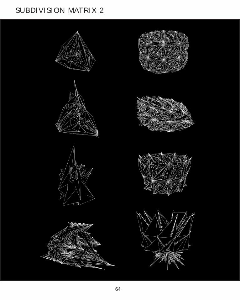
B.4 TECHNIQUE: DEVELOPMENT
In species 7 then, I decided to incorporate an additional section to my algorithm to encourage the points from the original shapes to shift and move. This species was a large exploration as I tried moving these points in relation to single, then multiple attarctor attractor points, on the range of surfaces I had been using, and with the different iterations. Many of these iterations provided unexpected and unintelligible results, but this system seemed often to create very different outcomes than the original.
SPECIES 7

62
SUBDIVISION MATRIX 2
SPECIES 5

63
B.4 TECHNIQUE: DEVELOPMENT
SPECIES 6
64
SUBDIVISION MATRIX 2

65
B.4 TECHNIQUE: DEVELOPMENT
SPECIES 7

66
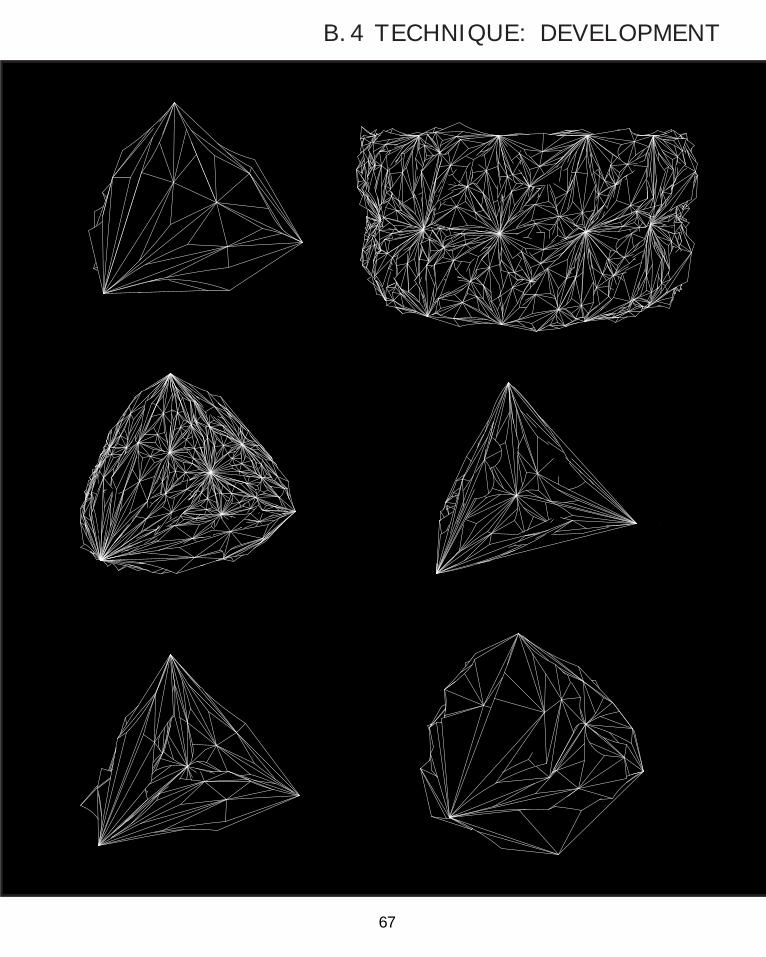
POST-CRIT DESIGN DEVELOPMENT
After presenting some of my developed ideas to the crit-panel in class, a number of suggestions were made that I have decided to develop further on here to be included in leading up to a design proposal. Of the few points made, the major point regarding the development stage of design was the potential for furthering the application of the subdivision beyond basic triangles, and developing them into more complex geometries
Extending the algorithm beyond the realm of basic triangles into more complex geometries was something that slipped my mind, potentially because the forms created were already so complex. After consideration, I decided that my effort should not be put into developing more complex initial surfaces, because the nature of Anenome and grasshopper in general require the same time of geometry to be re-inserted into the loop in order for the algorithm to run successively, that is, if an initial flat surface is inserted and an algorithm run that distorts form according to factors such as surface normal, when re-entered into the loop these surface normals may become impossible to calculate and cause surfaces to fail. So, without resorting to coding complex, sticking to planar triangles seemed the most logical.
However, it did make me realise there were other ways in which forms could be subdivided and affected in final iterations to enhance the design beyond these ideas in the current algorithm. These included adding curved lines instead of just straight ones, and changing the way in which the surface subdivided and folded. As such, I trialled a few iterations of this system to add to my scope of understanding.
67
B.4 TECHNIQUE: DEVELOPMENT
68
SELECTION CRITERIAWhen considering these interations in the concourse of the selection criteria, the parameters I feel should be the same. These initially identified qualities of Permeability, Integration, Materiality, and Detail all still apply to the site and so should still apply to the surface manipulation I have been exploring.
However, I don’t feel as though the selection criteria should be applied in the same way to these iterations as I did the previous. This is because the process is inherently not creating form but altering a surface. By this I mean, the previous iterations created and explored different forms and ways of relating shapes. As seen with the Hansmeyer development, this is a process that is applied to a form or surface, that alters it to try and achieve greater effect. As such, it is naturally addressing
them all, being easily altered for permeability, itself a form of integration, unrestrained by its material potential, and intricately detailed.
Instead, this process should be considered in relation to constructibility and design purpose. With this in mind, to address constructibility some of the simpler forms at lower loop levels would be easier to consider. However, when design purpose is taken into consideration as well, there is the potential that changing levels of complexity (and presumedly linked to looping) would be relevant to effectiving achieving the purpose desired for said surface, and so deciding directly on iterations does not seem productive in proposing ideas for what will ultimately be a group project. However, if to conjecture on potential purposes, the following iterations could be applicable.
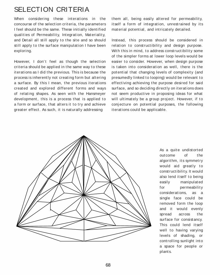
As a quite undistorted outcome of the algorithm, its symmetry would aid greatly to constructibility. It would also lend itself to being easily manipulated for permeability considerations, as a single face could be removed form the loop and it would evenly spread across the surface for consistancy. This could lend itself well to having varying levels of shading, or controlling sunlight into a space for people or plants.

69
B.4 TECHNIQUE: DEVELOPMENT
This negative normal iteration is interesting for its integration potential as it begins to create a cavity on the structure. This bulge could be taken advnatage of to account for plants or plant growth, give extra room to an otherwise tight space, or reflect a certain aspect of the site. This example has not controlled its intersecting faces particularly well, but tweaking could be done to make the shape possible.
This example of the post application of a curved line in the algorithm is particularly interesting for the extra detail is proposes for the surface. In some ways the strict, planar rigidity of the algorithm does not as naturally reflect way the environment it will be within, but with the added curved element there is a subtle hint at how this surface would better fit into its context.

70
PROTOTYPING PROCESSThe time had now come to begin exploring how this form could be constructed, and to do this I turned to using a CNC router to cut portions of the form into sheets of polypropolene. Initially I did consider trying to recreate my prototpes in a similar manner to Hansmeyer, by slicing my form into layers and cutting them out to form a rather solid whole. For hansmeyer this worked because he was needing to construct a column which needs to be strong and solid to support itself. Hansmeyer too had the time and resources to complete such an arduous task. I however, did not have the same time or resources, and more importantly I was considering the form in the light of a surface to be applied to our final form so cutting and piecing objects together to ultimately create a light and stable surface seemed a more viable pathway.
Initially I cut a small portion of the basic symmetrical form to investigate how the CNC router would deal with cutting very tight and small faces, and also to investigate how well the material responded to folding. The cut was done with a very thin engraving bit to try and minimize the loss of surface area. When cut, the polypropolene ripped up quite alot, although it was possible to clean it up afterwards. As visible to the right, the most intense parts of the face were the corner bits, where alot of the recursion originated. In some of the very close
parts it lost some surface but overall it seemed to cut fairly well. What was difficult however was some of the folding after it had been cut. For simplicity I just cut the form on one side. The polypropolene responded quite well to folding with the incision, but was rather resistant to it when folding against it. To achieve a fold that stayed and also went all the way back down to its tip I often had to result to scoring the plastic. This would help address the folding issue, but was inconsistent as the plastic was quite hard to cut.

71
B.5 TECHNIQUE: PROTOTYPES

72
PROTOTYPING PROCESSIn response to the difficult folding I decided to try a different cutting method and also to try and assemble a whole face. This time around I partially scored the cut, to replicate what I had been doing by hand but to a greater level of precision. I also tried using a different engraving bit that was a bit wider, with the hope that some added extra angle would help it fold nicely. Doing this had both good and bad outcomes.
The good was that the polypropolene folded really well this time around. Having the dual directionality for folding was also very useful when glueing it together because the complexity of the shapes means it was something unintuitive as to which direction the fold needed to be. In addition, the polypropolene responded surprisingly well to hot glue, sticking very well to itself without the need for tabs.

73
B.5 TECHNIQUE: PROTOTYPES
74
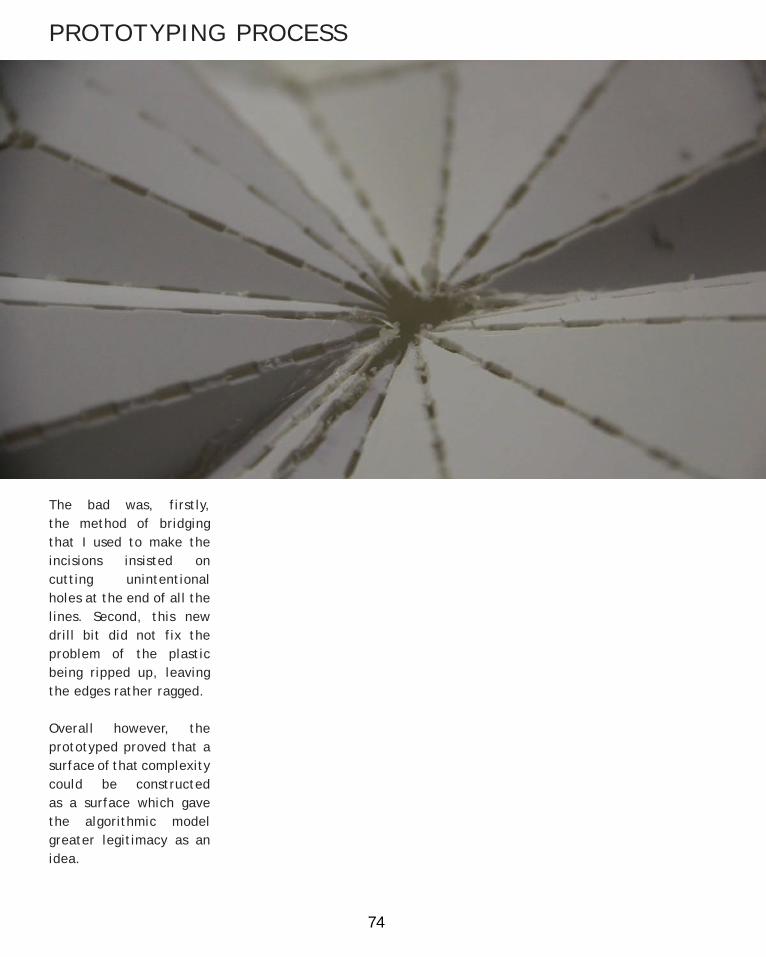
The bad was, firstly, the method of bridging that I used to make the incisions insisted on cutting unintentional holes at the end of all the lines. Second, this new drill bit did not fix the problem of the plastic being ripped up, leaving the edges rather ragged.
Overall however, the prototyped proved that a surface of that complexity could be constructed as a surface which gave the algorithmic model greater legitimacy as an idea.
PROTOTYPING PROCESS

75
B.5 TECHNIQUE: PROTOTYPES

76
PROTOTYPING PROCESS: MATERIALITY

77
B.5 TECHNIQUE: PROTOTYPES
Being a project to be sited at CERES however, the project required a greater engagment with thinking about the materials used. Firstly, as the Food Forest is to be a site for growing food the materials would require to be non-toxic as to not poison the produce. Secondly, with CERES being a symbol of sustainable development so too should the materials be sustainably sourced to contribut to this image. As such, I decided to play with timber veneers to see if they could potentially be used to produce a surface as a more sustainable option to plastic.
To do this I stripped a plank of wood down to a roughly 1.5mm strip to test its properties. The wood when scored could bend, but only in the direction of the score and only in the direction of the grain. If attempted to be bent in the opposite way to the score or against the grain the piece would just snap. In relation to our form, it meant that potentially the form could be constructed out of lots of individually cut triangles that could be then cut together, although this process seems overly tedious and potentially rather unprecise. The one directional fold however did give a scope for breaking down the form into a series of two connected triangles, which would involve having less points for adhesive and potentially a greater level of accuracy in construction.

78
DESIGN APPLICATION PROPOSAL
After thorough engagement with the algorithm and consideration of the iterations, I propose an integratable surface that could be used with various applications within the scope of the group CERES food forest project. The form itself is not specfically set, but would generally represent a complex series of connecting surfaces. In doing so, the idea holds the additional advantage of being adapted to the site and purpose specfically.
Example applications of surface for purpose include shading (with varying levels of permeability available), enclosure (such as for fungi or pot-plants), and decoration. To the right is an imagined application where the surface here is a hung
element of a larger integrated system for plant growing, with the surface here acting as a shading/light flitering element to mediate the amount of sunlight being received by a specific plant.
The surface is not intended to be specific to one area, it can instead be changed via the algorithm to provide form and position specific iterations to make the overall project more cohesive, whilst also itself providing purposeful functions. The way it too creates interest through detail intends to promote human interaction with the project both in the sense that it can be visually interest to examine and be relevant to the projects use.

79
B.6 TECHNIQUE: PROPOSAL

80
Having completed the subject so far, I feel a vast amount of information has become a lot clearer to me, at least in terms of digital architecture. The process of engaging with case studies and actually taking the time to understand how complex forms are being designed and constructed has been in a way humbling, partly in the way in which I can now see various logics in digital forms but also with through a sense of respect for the boundaries that have been addressed and stretched by these precedents. My main case study for example, the Michael Hansmeyer ‘Subdivided Columns’ is one I am constantly in awe of for the complexity that he is able to achieve and for stepping back into the realm of detail of which the modern era seems to have forgotten.
In terms of the Learning objectives I can see myself having come at least a little further in the way of meeting each of them. I feel my approach for tackling the brief, which we have been gathering slowly from CERES, has been appropriate in not limiting myself to things that may not eventuate to be possible but whilst still offering something worthwhile. My ability for generating varieties in design possibilities has definitely improved, particularly as my familiarity with grasshopper develops and my understanding of parameters and computing possibilities increases. I feel this is visible in my generous variations in both B.2 and B.4. Grasshopper has been a great way too in improving my skills in 3D media, with the way we have been engaging with recursion making be more aware of the role of scale and repetition.
This course definitely has made me more actively consider how form and architecture can be involved in space, and connecting those potentials with digital technology. In a similar sense I am also becoming more aware of how developing fabrication techniques are slowly bridging the gap between digital and physical potentials in form. I think particularly making some of my initial prototypes has fostered this knowledge as seeing an object of immense complexity on the screen
being broken down and turned into a real life object has unlimited my experience in this field. This is also relevant to precedent study, as understanding the process they take to creating their forms informs me as well.
It has also been really useful to have the crit-sessions before the due date, as the panels provided really useful outside-perspective feedback to help keep my project and line of thought on the right track. The major points of consideration that I gathered from my crit-panel were the following, and I hope that my consideration of them comes across in my journal somehow:- Furthering the application of the subdivision beyond basic triangles, and developing them into more complex geometries- A greater consideration of how the developed surface could cause or promote interaction with the structure- Developing reasons or connections (to either site or purpose) that determine how or which techniques (and to what extent) are applied- Focusing more attention towards the joints of the resulting structures, and how it may attach to other forms, and even itself
So far the course and project has been very enlightening and enjoyable, and I hope that the final stage continues to uncover more of this insight.
B.7 LEARNING OBJECTIVES AND OUTCOMES

81
PART B REFERENCESPg 24 - Image 1: http://designplaygrounds.com/wp-content/uploads/2012/08/BLOOM_02.jpgPg 24 - Image 2: http://www.bloom-thegame.com/main/wp-content/uploads/2012/07/THE-GAME3-750x500.jpgPg 24 - Image 3: https://encrypted-tbn3.gstatic.com/images?q=tbn:ANd9GcR5KmCm5Rt-hYHIPtPtPANhcl57crmQx6q2m9whagyj806Q8w2k1QPg 26 - Image 1: https://encrypted-tbn0.gstatic.com/images?q=tbn:ANd9GcRevf57g6EWFuHLFg3VF-Af7VTIJaptG0dLFv8QqDJ-MswhTJt7xwPg 26 - Image 2: https://c2.staticflickr.com/4/3305/3481330268_d12b8bd758_b.jpgPg 41 - Image 1: http://www.siemens.com/press/pool/de/pp_cc/2005/07_jul/sc_upload_file_sosep200502_10_072dpi_1280927.jpgPg 41 - Image 2: http://www.designboom.com/wp-content/uploads/2013/06/digital-grotesque-michael-hansmeyer-benjamin-dillenburger-designboom001.jpgPg 42 - Image 1: http://www.michael-hansmeyer.com/images/columns/columns1.jpg Pg 43 - Image 2: http://www.michael-hansmeyer.com/images/columns/columns4.jpgPg 43 - Image 3: http://www.michael-hansmeyer.com/images/columns/columns5.jpgPg 44 - Image 1: http://www.michael-hansmeyer.com/images/columns/columns3.jpgPg 45 - Image 2: http://www.michael-hansmeyer.com/images/columns/fabricated_columns5.jpg

82
PART C D E TA I L E D D E S I G N

83

84
GROUP PROJECT INTRODUCTION
Figure 1: Food Forest Example
85
Having completed our individual explorations into technique development in Part B, 5 of us in our tutorial came together to develop a design proposal as a group. Collectively we had all looked at techniques based on recursion algorithms, and so chose to focus on these for generating our design.
As previously mentioned, the group project had been set as designing something to contribute to the food forest at CERES. A food forest is a kind of gardening concept that utilises the qualities of real forests to create a mini-ecosystem that is self sustaining and also produces food.
There are 7 qualities to a food forest (Jo/The Desert Echo, 2013):1. Canopy (large fruit and nut trees)2. Low Tree Layer (small fruit trees)3. Shrub Layer (currents and berries)4. Herbaceous Layer (herbs)5. Rhizosphere (root crops)6. Soil Surface (ground cover crops)7. Vertical Layer (Climbers, vines)
The result of these layers is intended to be a fruitful, symbiotic relationship, where canopy trees and climbers can provide shade against harsh sun for lower plants, herbs help increase nitrogen levels for the shrubs, and their combined leave litter helps fertilise the ground, etc. It is quite a complicated system to develop, and not only does it require a large degree of planning, it also takes a generous amount of time for the plants to grow and develop these relationships with eachother.
From this initial description alone, potential ways in which we could help develop this system were identified, such as sacraficial structures for vine growth, temporary shading, etc., but first we decided as a group to analise the site and see if any site specific considerations arose.
C.1 DESIGN CONCEPT

86
SITE INTRODUCTION
CERES, the site of this food forest, is located in the inner Melbourne metroploitan suburb of Brunswick East, and exists alongside the Merri Creek. It is quite well located as a central point for much of the northern public to engage with, a 15-20 minute tram or bike ride from around the University of Melbourne area, and a similar distance for residents of some of the slighlty more outer suburbs, such as Coburg or Preston. And CERES already takes advantage of this fact, encouraging locals to partake in classes, buy and sell fresh, organic
produce, as well as providing services such as free bike repair. All of this effort is done in an attempt to be an example to the melbourne public of the benefits and possibilities of environmental and sustainable living possible in the Melbourne area itself.
Figure 1: Map 1
87
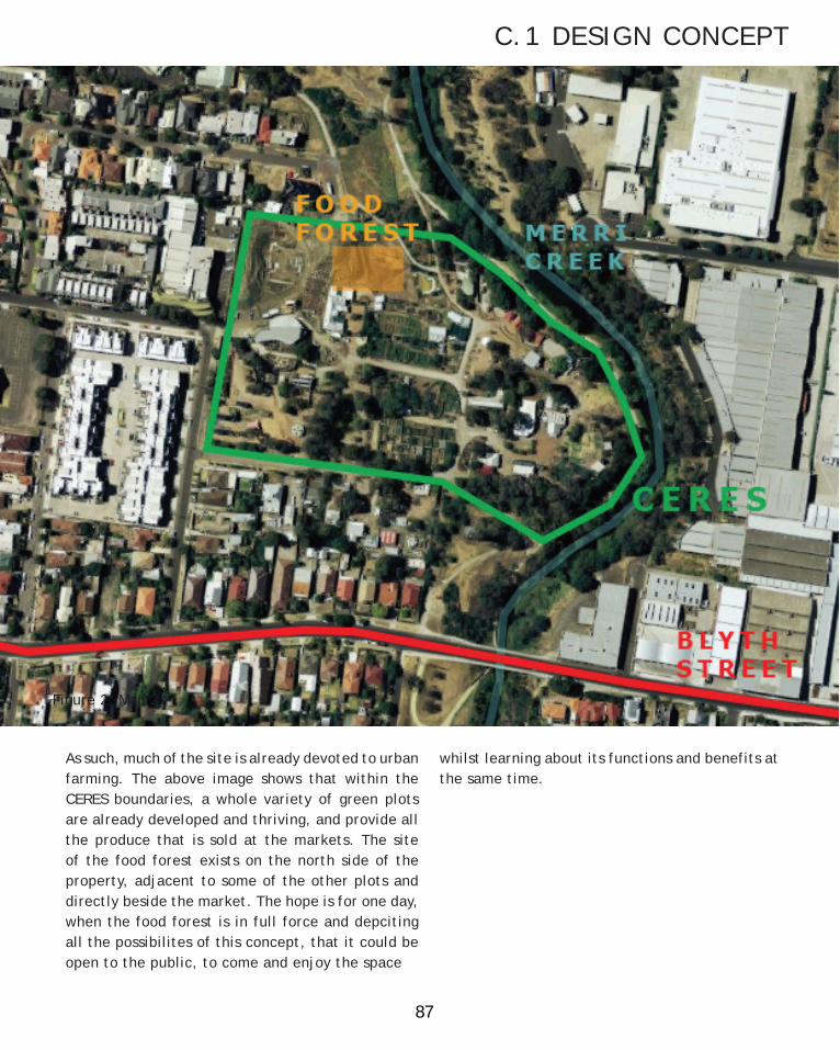
As such, much of the site is already devoted to urban farming. The above image shows that within the CERES boundaries, a whole variety of green plots are already developed and thriving, and provide all the produce that is sold at the markets. The site of the food forest exists on the north side of the property, adjacent to some of the other plots and directly beside the market. The hope is for one day, when the food forest is in full force and depciting all the possibilites of this concept, that it could be open to the public, to come and enjoy the space
whilst learning about its functions and benefits at the same time.
C.1 DESIGN CONCEPT
Figure 1: Map 1 Figure 2: Map 2

88
SITE OBSERVATIONS
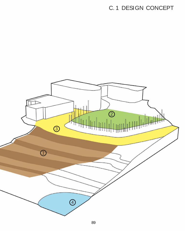
A close up of the site offers further insight into the possibilites for the food forest. Work has already begun on the food forest, albeit having a rather slow beginning, with initial efforts being made over the past 2 years, and the first major planting and cooperative move beginning this year. The site is of a decent size, but nothing overly ambitious. The area of the depicted food forest space (1) is about 780m2, and the public grass area (2) about 480m2. When we as a group travelled to the site, the following site observations were made:
1
2
3
4
89
1
2
3
4
C.1 DESIGN CONCEPT

90
SITE OBSERVATIONS
1 Site of the Food Forest. It consists of 4 flat runs (light brown), each preceded by a terrace of varying sizes (dark brown). Plants
are envisaged to grow over all of this area, with the majority of crops growing on the runs, and then various trees and bushes intended fror the
terraces. Planting of some of the larger trees has been completed in earlier years, and this autumn the first crop has been planted on the uppermost run. The Food Forest area is flanked by access paths on either side, linking the road and the pond.

91
2 Small public access grass area. This space leads directly out from the cafe at the back, and is surrounded by a wooden spike fence. The fence blocks most of the views on the
Food Forest unless you get right up to it and stand on some of the landscaping rocks. It is a very open space with steep sloping sides, with no real specificed use other than general public use.
C.1 DESIGN CONCEPT

92
3 Access road. This road links from near carpark (off the map, to the right) over to the market and chook pen (left most building). It acts as a divider between the public grass area and the food forest, with fences on either side. This road is used for deliveries to the market and also to transport black water from the market area. We were informed by Renato, one of the food forest builders and planners, that it must be left open to accommodate these uses.
S ITE OBSERVATIONS

93
4 Pond. A marshy part of the site currently used as a small outdoor water storage location. It flanked by a series of water tanks and is left to exist very naturally, overgrown with plants that inhabit the area.
C.1 DESIGN CONCEPT

94
SITE ANALYSISSomething we noticed occuring quite significantly on site during our visit was the presence of soil erosion, particularly on the terraces. Renato confirmed with us its existence and informed us that it was quite a problem for them. Long term, this was not projected to be an issue as once the food forest had been built up the roots and mass of the plants would both help hold the soil together and absorb alot of the water that would be causing this erosion. However, in the short term this issue was very prevalent, as maintaining a strong soil cover is a vital component in creating an environemnt for plants to take hold. Currently the only solution used to combat this has been the placing of solid masses, such as rocks and logs to physically hold back the soil.

95
We were also made aware of the plan to involve their chicken flocks in the food forest. Two flocks are set to roam the area, one taking the higher paths, and the other the lower ones. Other than farmers and volunteers involved in the developing of the forest, they, in the short term, represented to us the primary users of the site as well. Renato informed us that the runs would provide most of their dietary needs, but currently lacked any water sources.
C.1 DESIGN CONCEPT

96
SITE RESPONSE - EROSION In coming up with a response strategy for the site then, we decided to focus initially on addressing the problem of erosion we saw on the site. As a significant negative factor to the development of the food forest, we felt it important to identify additional solutions to combat this. In this issue we identified (rain) water moving through the site and along the surface as being the main influence in this erosion event. As such, we decided it appropriate to create an approach to controlling and harnessing this water.
To do this, an understanding of how water influences erosion was necessary, and a number of factors exist. Firstly, when rain falls and interacts with the surface it hits, it has 2 main avenues in which it can continue (Morgan, 2005). It can either flow along the surface towards a low point (this being a river or lake) or seep into the surface (ground) and slowly flow down towards said low point through the soil, the low point in this case being the Merri Creek.
The avenue which the rain will tend to take depends on the characteristics of the surface. If it is relatively perveous, like a loose soil, much of the water will seep into it, and once it becomes fully saturated, it will flow down. If it is more imperveous, perhaps like concrete, the water would likely tend to flow over the surface without penetrating downwards. The angle of the slope also affects how much water seeps into the ground, as steeper slopes give the water less time to absorb in, and so encourage surface flow.
These factors affecting how the water moves is important to our context, because it is this moving surface water that encourages the most surface erosion. When water flows over the surface, it will collect with it any loose particles, and drag them down slope with the flow. In this situation, slopes are also the most at risk because the soil particles are the least supported, and the angle means gravity can make the water flow faster.

97
Seep or flow
Slope encourages flow
Loose particles picked up
C.1 DESIGN CONCEPT

98
As a result of this understanding, it made sense for us to develop a system to minimise the amount of water that is allowed to run along the surface of the food forest slopes, and further the erosion effect. This made us look towards the road and the public grass area, as they both exist above the food forest and could have onflow onto it. In addition, both of these parts of the site, particularly the road, would be quite hard and relatively impervious as they are both frequently travelled upon, likely causing the soil to compact and be less prone to water permeability.
This resulted in us imagining creating a catchment area to initially catch this water and prevent it from flowing down. We were told the road had to be left clear, so we focussed the catchment on the public grass area. In this situation, using our recursion algorithms we could create both a system for catching and controlling water, and create something of interest for patrons in the cafe, that could draw their attention first to it and then to the presence of the food forest.
The next question was then what to do with this water. If we were only trying to protect the site we could have just directed the water away, potentially to the river, but it was reasoned that this water could still be used for the food forest, just delayed as to discourage mass amounts of water causing erosion. Firstly then, we would need a method of transporting this water, and so imagined that a system for distributing the water down slope could be created. The use of L-system logic could be used to build a river like construction that spread over the food forest and could allow water to be distributed where needed.
Subsequently, objects or structures to utilise or store this water would be necessary. Thinking of the other needs of the site, it was reasoned that we could direct water to some kind of chicken trough for the flocks to drink from. Water storage would also be important so tanks could be built around the site. We also discussed how encouraging bees to a site is very important as they are so endangered currently, so utilising water to supply a bee enclosure could be an effective use of the water also.
Having then planned to build all of this structure, we deemed it necessary to take into consideration how the effects of these structures could be utilised to best affect the food forest itself, and a potential planting plan that could evolve from the restraints our structure placed upon it.
These considerations as a whole became our site response. We decided that as the erosion problem was temporary, dependent on the development of the plants, that so too should be our strucutre. This would be achieved through materiality, and the ability to repurpose the structures. As such, in our group of 5 we split up these aspects of the response into 5 components to allow us each to develop a particular part in detail. These parts were:1. Top Catchment2. L-system distribution system3. Water retainment (Troughs and tanks)4. Bee Enclosure5. Food forest adaption.
The part I was designated to focus on was the water retainment component.
S ITE RESPONSE - EROSION
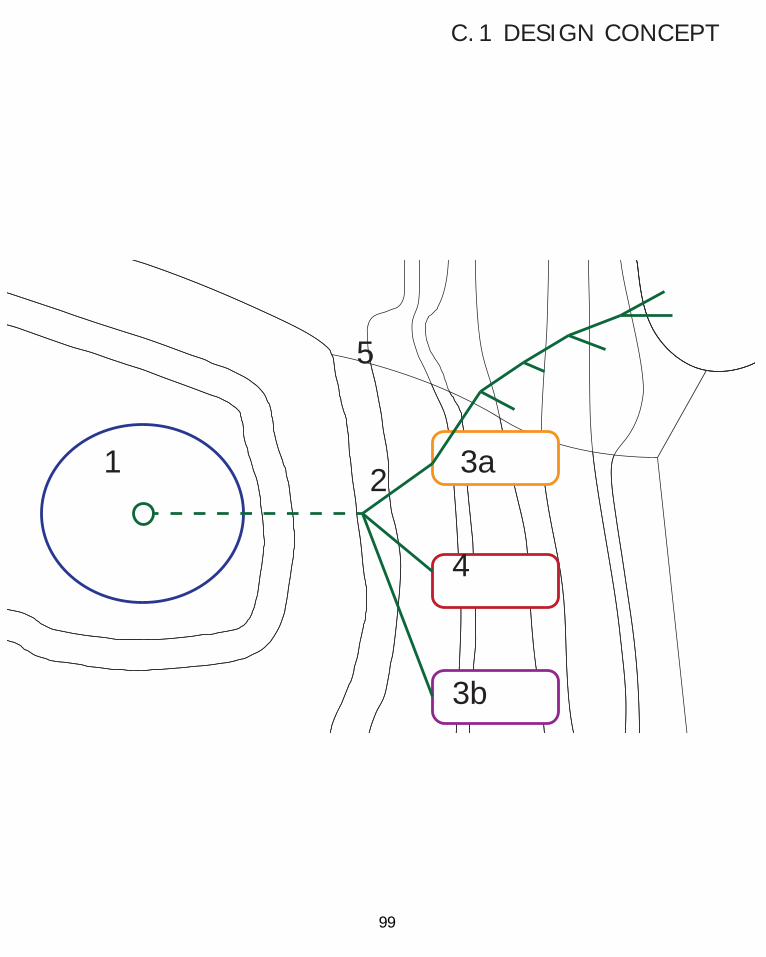
99
1 2
4
5
3a
3b
C.1 DESIGN CONCEPT

100
To begin my component then, I decided that before experimenting with form, I should be more aware of what the reality of the water situation was for the site. As such, I wanted to know how much water the food forest needed, and how much water it actually received. I reasoned that the water requirement of the site would depend on the water demand of plants, and so used this as my guide.
According to Irrigation Australia, in a relatively temperate and exposed site, like at CERES, a garden needs approximately 10mm of water per week during summer, and 5mm per week during winter. This water is required to seep into the root range of the plant, which varies differently for each plant, but is generally regarded to be at a level within a 30cm depth from the plant base (Irrigation Australia, ). Thus, knowing now the required water for maintaining a garden, how much water is actually received?
ADDITIONAL SITE ANALYSIS
The Bereau records indicated that in the Brunswick area, approximately 500mm of rain was received over the past year, averaging roughly 1.4mm a day, or 9.6mm a week. This initially seems positive as this is very close to the summer water required, and well above the winter requirement. And, as mm of rainfall is an average across all surfaces, the extra rainfall caught from the catchment area could be used to meet the additional demands.
However, rain does not fall consistently, especially in the drought prone state of Victoria, and nor does it fall evenly through out the months. A breakdown then of yearly rain is needed to properly understand site needs.
The graphs depict a yearly breakdown of rain fall across the Brunswick area. From this data, a few relevant points are visible.
1) Summer does not meet its needed rainfall. This means that enough water must be stored from Spring to meet the lack. Thus, if summer is 55mm short, then around 42900L (55x780m2) would need to be able to be stored. However, this is presuming that all rainfallis observed by the food forest. As discussed earlier, a portion is most likely going to be lost as run off, so this amount would be more. This amount may also be subsidised by utilisation of the catchment.
2) Approximately 75% of rainfall falls below 2mm in a day. Thus in general the system will be dealing with relatively small amounts of water. This should mean that the system would not be under heavy stress most of the year, and should be able to cope with those few off chances that the rainfall exceeds 5mm.
As such, the water needs/constraints of the site summarised are:- Site requires the capacity to store water from spring to supply the needs of summer.- Water needs to be slowed down and prevented from running directly over the soil.
Fig. 1: Irrigation Australia

101
Fig. 2 B.O.M.
Fig. 3 B.O.M.

102
ADDITIONAL SITE CONSTRAINTS
When considering the site for use of the chickens as well, Renato informed us that the chickens were planned to be let free to roam the food forest in the fashion of the above plan. The blue area would represent the first flock and the red the second. The flocks were to be kept seperate by allowing them each to have access to different runs. Of the two runs they were allocated, only one would be initally accessible at a time, depending on the crop they would be growing. It made sense then, that a water trough for each flock should be made, in such a way that it serviced both runs at the same time. They were also intended to be placed towards the side that the chickens entered the run, to make it more central over the course of their area.

103
45cm
The size of the tank’s foot print is also desired to be minimal to allow as much as the surface as possible to bear plants.
The chicken troughs then, would be required to be accessible by a chicken, and also service both levels of the terrace.
C.1 DESIGN CONCEPT

104
FORM GENERATION
Having completed a detailed analysis of the conditions present in considering the trough and tank, I then began my inital form generation. As the structure that would lead into the tank and chicken troughs was planned to be designed using L-system logic, it made sense to use L-systems to generate form as well for these components to develop a coherency throughout the overall project. If a solid form could then be created from it, I would then
have an opportunity to incorporate the surface manipulation algorithm into the design to develop a further level of complexity. This lead me through a process of experimentation with L-systems. I used the starting lines to represent forms evolving out of the top connection with the overall L-system, and then to develop a form that would develop out of the ground and down from the connection, forming a focal point in the middle.

105
I also began testing ways in which these forms could be converted into solid masses. Applying drapes to L-system distributed balls came with limited success, the result being some interesting, yet very heavy and warped forms
C.1 DESIGN CONCEPT

106
FORM GENERATIONI further explored developing the L-systems into solids in grasshopper, and found that various methods of triangulation produced interesting results. Creating faceted domes in response to the end points of of the L-system produced promising solids. Application of the delaunay tool, also formed some very interesting surfaces. I tried combining the two in an algorithm, extruding the edge of the
delaunay surface to make it solid, and joining them together. These created some rather interesting planet-like forms that seemed capable of being used as water storage. Lower level incarnations of the form also seemed to be compatible with surface manipulation, which seemed to be very intricated received by the forms.

107
C.1 DESIGN CONCEPT

108
Another important consideration in trying to bring these forms into reality was their structure and materiality. If they were to be large forms, then they would either be forced to sit on the ground, or be suspended by a more substantial structure. Both of these solutions suggested to me that a large foot print would be required so I chose not to follow that path.
FORM GENERATIONConsidered as smaller elements, it seemed to propose that the ‘tank’ or ‘trough’ did not have to be a solid mass of water, but a set of connected elements distributed around an area. I imagined these elements then being potentially distributed in an L-system manner, using pipes to connect them all. Conceptually, this really appealled to me. By decentralising the load usually associated with a tank or trough, it could be created by a more dispersed structure, and also be more representative of the L-system logic trying to bring coherency to the overall project.

109
Following on from this idea, I realised that rather than making the tanks held up by an L-system, I could make the tanks themselves the L-system. For this idea I looked towards the Bloom project which I studied earlier in the semester, and how they used single elements repeated that could connect to themselves in a variety of ways to generate form. These forms could be tested and changed very easily in grasshopper and used to observe what final forms may arise, a method I could too could take advantage of. Incorporating the tanks as such would also maintain this coherency of L-systems very strongly, whilst also being very practical. This practicality would be found through the ability to be re-used in various forms, either throughout the site, or after the need for our system had finished.
C.1 DESIGN CONCEPT

110
The only problem with this concept that remained then, was the tank. To do this, a tank part that was able to connect with its neighbours, as well as the ability to be structural would be needed. Connections could be added to the form found from my initial investigation, but it would be difficult to develop with in a way that they could be structural, without overly distorting their character. So, taking inspiration from the Bloom project, I decided to design these tank elements around the way the tanks would connect. I imagined, to combine the needs of water retention, strutural integrity, and movement of water the form would need to be hollow, be able to rest on eachother for support, and for the connection to not only be a joining elements but the point where water could pass through (below is a rough diagram of this concept).
FORM GENERATION

111
So, I began brainstorming possible forms and variations of this component. I played with length and direction, number of connections per piece, sets of pieces, and pieces with specific functions. The main component I decided on early was having a cylindrical connector to join the tanks, that would stick out from the bottom of one, and sit into the slot of another. Having it cylindrical meant it could be rotated 360 degrees to any direction I needed. I debated between having the connector sit into a sort of ball joint or as a flat surface. The ball joint I reasoned may have a stronger connection between the tanks as they would have more surface connection and may ease pressure off the cylinder as being the sole connection, but would more drastically restrict how closely connector points could be positioned. As such, I decided that leaving that connection flat, and indeed the top surfaces flat could provide more scope for possibility of junctions between tanks.
Flat vs. Ball Joint
C.1 DESIGN CONCEPT

112
FORM GENERATION
Component Length
Top Hole Seperation
Initial Offset Distance
I decided using a simple two piece connector, both as a practical component and as a place to test how I could make this system work in grasshopper. To do this, I initially created the form in grasshopper so that the piece itself was very editable. The benefit from this would be, as like in the bloom project, that the initial form itself could be easily altered and updated to respond to the needs of the overall form when applied in an L-system.

113
I then reasoned that while the top was being left flat and smooth, the sides could incorporate detail through my surface algorithm. To make relatable to the process though, I set the algorithm up so that lower sections would receive higher levels of manipulation, and higher sections lower, to represent a kind of connection with the ground, the detail growing more intense as the water moved away from the overarching L-system and closer to the ground.
C.1 DESIGN CONCEPT

114
I then created an algorithm to distribute these tanks, with new tanks repositioned in the connecting holes of the previous and rotated a determined amount. The digram below visually represents this process. I then began experiementing with the forms created from this. An instant realization was the manner in which the tanks tended to intersect with repeated side-by-side iterations, making the forms impossible. I tried creating some of these
FORM GENERATIONimpossible forms, and then manually going through and deleting unnecessary or overlapping tanks, but found the process tedious, rather unprecise, and overall against the idea of generating these forms with my definition. Nonetheless the process still represented what was possible with the definition. I also tried have alternating evolution patterns, where on the first cycle, both holes would generate a new tank, and then on the second only one. These were less crowded but still inded in similar results.

115
C.1 DESIGN CONCEPT

116
FORM GENERATION

117
C.1 DESIGN CONCEPT

118
It then dawned on me that these elements were also creating their own structural issues. Individual elements couldnt be left to just span out as they would be left toppling over. As such I realised I had to either find configurations that supported the tanks more evenly, or changed the tansk to ones that could more efficiently support themselves. I also reasoned that if a span could be supported at either end, supporting ties could be used to hold the elements together.
FORM REFINEMENT

119
I also decided to alter how the surface manipulation was applied to the tank. I adjusted the grasshopper mesh conversion so that the resulting mesh was not divided an a perfectly even pattern, but to be more simplied with varying surfaces sizes. This, in my mind created more dramatic surface effects and suited their purpose more.
C.1 DESIGN CONCEPT

120
From these ideas I developed two different systems, one to meet the tank requirements, and one to address the trough ones. The tank, utilised the stacking method and had a centralling stacking core. This core was supplimented by circling arms that spanned 4 tanks. These arms were not actually connected to the overall water tanks flow, but
FORM REFINEMENTcould be utilised for contextual purposes, such as providing opportunities for vines or serving as a base for growing small herbs. This method was also favoured for the tank, as it could be built as high as was needed,, both in terms of meeting the connection points from the L-system and being able to store the required amounts of water.

121
C.1 DESIGN CONCEPT

122
The chicken trough followed the alternative method, of self spanning blocks. They were applied however, to run with the slope, gaining their support from being dug into it. The rationale for this design was for the initial input to be split, leading water to the top and bottom levels. The bottom level would utilize a series of open-topped tanks stacked towards the bottom to allow water to overflow and still be retained and accessible, even when rain was very intense. The top level would utilise the fact that some of the overarching L-system cut into the ground before reaching it, and could be used in conjunction with the tank to provide water for the chickens.
FORM REFINEMENT

123
C.1 DESIGN CONCEPT

124
These tanks put back into the context of the group project then, give this. To the left is the catchment area with a central collection point. This leads under the road and out into the food forest, where the L-system distributes collected water. The pipes are semi-circular and open to the air so as to catch water themselves. This leads into the central bee hive, and off to the 2 tank sections and the 2 troughs. The major excess leads straight off into the pond.
GROUP PROPOSAL

125
C.1 DESIGN CONCEPT

126
MATERIAL TESTINGThe material I turned to first was concrete. I reasoned that when set, it would be water-tight, and being plastic, could be poured to fill a mould and produce the surface qualities desired. This mould could then be provided by the plastic prototype I had previously produced. To do this, I lined the prototype with shrink wrap to water proof it, and created a border around it to contain the concrete. I then poured the concrete in and let it set.
Unfortunately during transporting the model it was knocked and shattered before I could properly view the prototype as a whole. However, it wasn’t a complete waste of time and I learned a few valuable things from the process. The first was that moulding procedures need to be left to have enough time to appropriate cure. Partly the reason why the model shattered. The second was that concrete is very receptive to the formwork it is placed in, and will represent all the inaccuracies that it is exposed to. This can be seen in the
The problem still presented by this model though, was developing these ‘tanks’ to include the surface manipulation and still be water tight. The prototypes I had produced so far, whilst maintaining their form did not provide a robust or sealed enough form to handle being constantly exposed to water. The materials of these prototypes now also seemed unsuitable. The plastic model would provide the water-proofing, but did not seem like a friendly addition to the food forest, something that would definitely be removed at the end of its life time. The wooden example, whilst more suitable to being sacraficial, did not provide any level of suitable waterproofing, without being very dense, heavy wood. I decided I had to find a more suitable material to meet these needs.
underside close up image to the right, where the folds in the shrink wrap have both left ripples in the form, and partially prevented the concrete from representing all the sharp edges in the form by smoothing them out. A more precise mould would then be needed to replicate this. Using the light plastic prototype as the mould also proved to be unsuitable because it deformed under the weight of the concrete. Considerations of mould reinforcement would need to be included in further attempts.

127
C.2 TECTONIC ELEMENTS AND PROTOTYPES

128
MATERIAL TESTINGConsidering concrete then as a potential material still provided me with both a few advantages and a few problems. The prototype proved that using a plastic substance had a considerable advantage of being able to take the form it is set in. If a suitable mold could be made, it would be an effective way of creating detail, without much more effort than if the mold had no detail. However, concrete is also quite heavy, and so could be a problem unto itself without reinforcement (especially for the spanning members particularly when filled with water). Molding issues also arise when trying to create a hollow object. For this to be possible, at least 2 seperate shells would have to be individually set and then fused together, which could affect the water-proofing of the tank. Making the mold would also be a task in itself. Thus it was clear that finding a relatively plastic material to apply to a mould that was more suited to being hollow and a bit lighter would be ideal.
I decided to meet myself half way and try using clay. I reasoned that clay could be easily molded to a shape, would be water tight when fired, as well as quite self supporting. To create the mold, I would first 3D print a prototype of the form, cast it in plaster, then use that plaster mold to shape the clay and create a replicated tank. It also made sense that once the molds were created, the task of creating tanks could be taken up as a community activity at CERES, to both teach clay making and invlove the community in the building process of the food forest, which is something that they are already relying on.
So I set out to reproduce this procedure. I 3D powder printed the prototype with the early version of the surface manipulation at about a 1:3 scale. The surface came out quite well but was very subtle, even in person, and I feared this detail could be lost in the molding process. I was very pleased though with it as a proof of creatibility in terms of creating such detailed surfaces.

129
C.2 TECTONIC ELEMENTS AND PROTOTYPES

130
As it was a powder print, I was concerned that when exposed to a plaster mold, the plaster would ingrain itself into the prototype, so to add a layer of protetction I coated it in latex. I taped over the holes, and added a centre line to guide the molding process.
MATERIAL TESTING

131
IThe layer had to be thin so that as much of the subtle details could be retained as possible. n drying the latex bubbled, both probably because of the unskilled way in which I tried to apply it, and from the thin layer that was applied.
C.2 TECTONIC ELEMENTS AND PROTOTYPES

132
MATERIAL TESTING

133
A two part mold was then made, again using latex to seperate the two halfs. Once set, the mould was cut open and the mould exposed. As first, the 3D prototype resisted being removed from the mold. Weak points around the top openings also collapsed when pressured, but with some effort a mostly intact prototype was able to be preserved.
The resulting mold revealed to me a few of the inaccuracies of my molding process. Firstly, many of the latex deformations were religiously preserved, similar to the way in which the shrink wrap had been preserved by the concrete. I had also not thought to try and force as much of the air out of the plaster as possible before inserting the 3D. Both of these can be seen in the form left imprinted along the edge of the mold.
C.2 TECTONIC ELEMENTS AND PROTOTYPES

134
When trying to fill the half molds completely with clay, it could not be pull out cleanly and would break and deform drastically. As such, I was forced to create the form in sections, making strips for the edges and joining them, and rolling flat surfaces
MATERIAL TESTING
for the top and bottom. The top spanning parts also proved to be troublesome when being put together as the clay when warm would sag across the short span. As a result I had to fill these parts will wire strips to act as reinforcement.

135
C.2 TECTONIC ELEMENTS AND PROTOTYPES

136
MATERIAL TESTING

137
I made 2 attempts at recreating the forms and then baked the results. I was not particualrly happy with these results as they hardly resembled or maintained the quality and detail desired. As suspected, much of the side surface detail was lost in the mold, the retention of this not helped by me having to hand craft the elements together rather than relying solely on the mold.
Having said this, many lessons were learnt in the process. I realised attentiuon to detail was very necessary in the model making process, as its quality dictated the final result. I also now understood that a multi-part mold would be needed to make this work more efficiently, sot aht the mold could be pulled away in stead of the clay, allowing it to maintain its form.
C.2 TECTONIC ELEMENTS AND PROTOTYPES

138
Having tested the application of clay I decided that it was very useful for what i was trying to achieve, but the manner in which it was applied hindered results. Instead I needed another plastic alternative to create the finer details. This is when I discovered slip and slip casting, and have since decided on this method as the way in which the tanks would be created. Slip is liquid clay, and so could be used to plastically fill a mold. The process of slip casting is also extremely useful for creating hollow objects. As slip has a high water content, when exposed to a porous mold, such as plaster, the moment it is cast in the mold water begins to be drawn out from the points that are in contact, forming a shell on the outer side. This shell thickens the longer it is allowed to set, and once the desired thickness is achieved, the remaining slip is poured out and a hollow product is left. The implications of this would be that the same (yet improved) process I used to test clay could be used to make slip cast versions of the tank, that would be more easily and precisely constructed than the handmade application of normal clay.
The only drawback with this in relation to my journal, is that by the time I had decided to use this method, I feasibly did not have enough time to test the process. As the mold is needed to absorb the water, a bone try mold is needed. This is required to sit for 3-4 days after being cast. Once the slip is set, it also takes 7-10 days to be properly fired, which must be done professionally and not just any oven, like I had originally attempted with oven bake clay. However, having tested the methods in which this process would revolve around, I am confident that excellent replications of the tank could be created using the slip cast method.
F INAL MATERIAL CONSIDERATIONS

139
Figure 1: Grape slip cast. Shows the potential of form from good mold and the use of slip.
C.2 TECTONIC ELEMENTS AND PROTOTYPES

140
When we presented our project idea at our end of semester presentation, the crit panel provided a lot of interesting useful comments on our design, along with suggestions and tips. I found the feedback very valuable because it came from a few different perspectives. Feedback from within Studio Air came from tutors giving us critique with their digital design understandings, an architecture PHD student provided additional comments with a wider design perspectives and logic, and a representative from the food forest, Monique, was also there and was able to provide feedback with relation to response to the site and its needs. Of particular note from this feedback was the following:
- The catchment area, instead of being nestled into the ground, could have been suspended in the air like a roof or shelter- Additional shading could have also been implemented on the food forest site for both plants and volunteers, of which the catchment area algorithm could also have been included- L-system distribution pipes could have been supported in a more parametric fashion, as opposed to the poles that initially held it up. - The inidividual tank modules could have been pushed more parametrically- A system for access of the water collected in the tanks needed to be defined- It was excellent that erosion was being responded to in the response, but as the surface was so hard, water was never properly penetrating into the lower level, and so a design response for this would also have been effective
All of this feedback was very relevant and justified, but for the sake of this journal I will focus on the comments relevant to my undertakings.
The first comment was that the individual tanks could have been pushed and refined more parametrically. The truth in this is that although I have applied surface manipulation to the tanks, the forms have ended up quite simple. This point is also relevant from the perspective that the tanks were designed based on function and then adjusted with parametrically, instead of being parametrically based and altered to suit function. However, I would dispute that the parametric focus in my design should revolve around the recursive, L-system process I used to experiment with potential forms, and that utilisation of a simple form only helps define this process. Instead, the individual tank elements should be well thought out and rationalised, and it is this aspect that I have tried to demonstrate so far, but also could do with alot more work.
The second comment that referred to me was the lack of a system to access the stored water. I admit that this fact had been initially overlooked and so had to be addressed post crit.
The third question was more group orientated but I realised that as I was developing the points at which water was to be slowed down, it should affect my design too. This too I attempted to address post crit to tie the final parts of the design together.
CONSIDERATION OF CRIT FEEDBACK

141
C.2 TECTONIC ELEMENTS AND PROTOTYPES

142
In addressing the comment on refining my tanks, I appreciated that the tanks could be completely re thought and designed, but decided to focus this intent on my current design for the short time that I had, to make this form more cohesive.
Looking at my design, the part that I immediately realised was sketchy were the wrapping arms. I was
RESPONSE TO CRIT FEEDBACKsuggesting to support these spans with brackets, but the problem there was that so little of the tank connected to be supported by a bracket that it didnt make sense. So, as they elements did not require the extra hole, I simplified the spanning elements to have a single hole and be narrower. This would hopefully provide the brackets with support of more tank, and make it more cohesive.

143
When considering the comments on how to utilise water and how to re-introduce it to the ground, I realised both of these issues could be solved with the same solution. Instead of thinking of tank structures as ‘tanks’, I realised they should instead by seen as ‘junctions for slowing water’. By this, I mean that water introduced to the structure would be forced to curve itsway down to the bottom and then be temporarily stored. At the bottom they would then be fed into a short vertical pipe with a few meshed openings in it. The two on the bottom would be open to the soil, and would allow the water to slowly seep its way into the soil. Whilst that water was slowly seeping out, the excess water
being built up behind it would be directed out through a higher pipe, that would pipe the water directly into the big storage tanks just off site, near the pond. This way the water could be accessed and stored like all the other water and used for correcting the food forest as the caretakers saw fit. Thus, instead of being required to meet specific water targets for storage on the food forest itself, these water loads could be combined with the whole, and the structures that existed on the site would be arranged so as to maximise the spread of water re-introduced to the soil. Thus, both the issue of water access and water re-introduction could be solved in one simple solution.
C.2 TECTONIC ELEMENTS AND PROTOTYPES

144
FINAL MODEL BUILD
Thus, to demonstrate form I created a 1:2 scale model from MDF. 25mm MDF sheets were first 2 part hogged, creating a hollow, the top and bottom holes cut, and then the form was cut out.

145
C.3 FINAL DETAIL MODEL

146
FINAL MODEL BUILD
This provided the top and bottom hollow pieces of the tanks. The bottom connection that sticks out was cut out with the same process. These elements were then all stuck together with PVA. The brackets were laser cut and the base box CNC’ed.

147
C.3 FINAL DETAIL MODEL
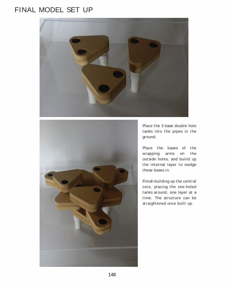
148
FINAL MODEL SET UP
Place the 3 base double hole tanks into the pipes in the ground.
Place the bases of the wrapping arms on the outside holes, and buiild up the internal layer to wedge these bases in.
Finish building up the central core, placing the one-holed tanks around, one layer at a time. The structure can be straightened once built up.
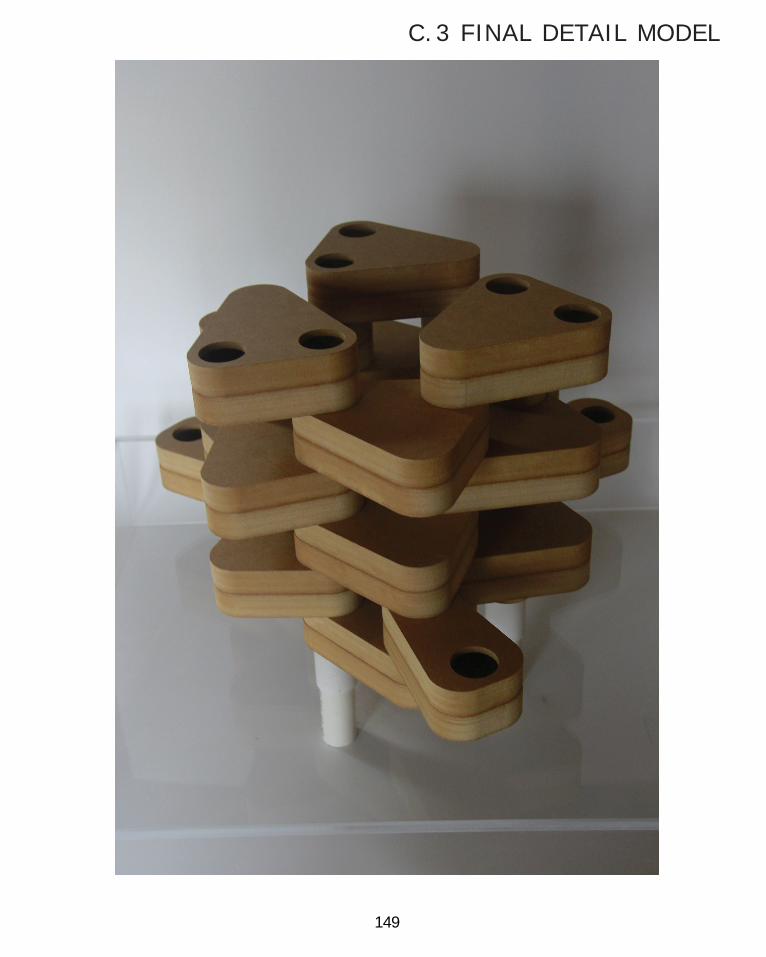
149
C.3 FINAL DETAIL MODEL

150
Insert the arm tank into its slot, and then slide the bracket over. For the last tank, insert the tank into its hole with the bracket handging loosely. While the bracket is still loose slide the tank into its position and then slide the bracket on. The form is complete.
F INAL MODEL SET UP

151
C.3 FINAL DETAIL MODEL

152
FINAL TANK DESIGN

153
C.3 FINAL DETAIL MODEL
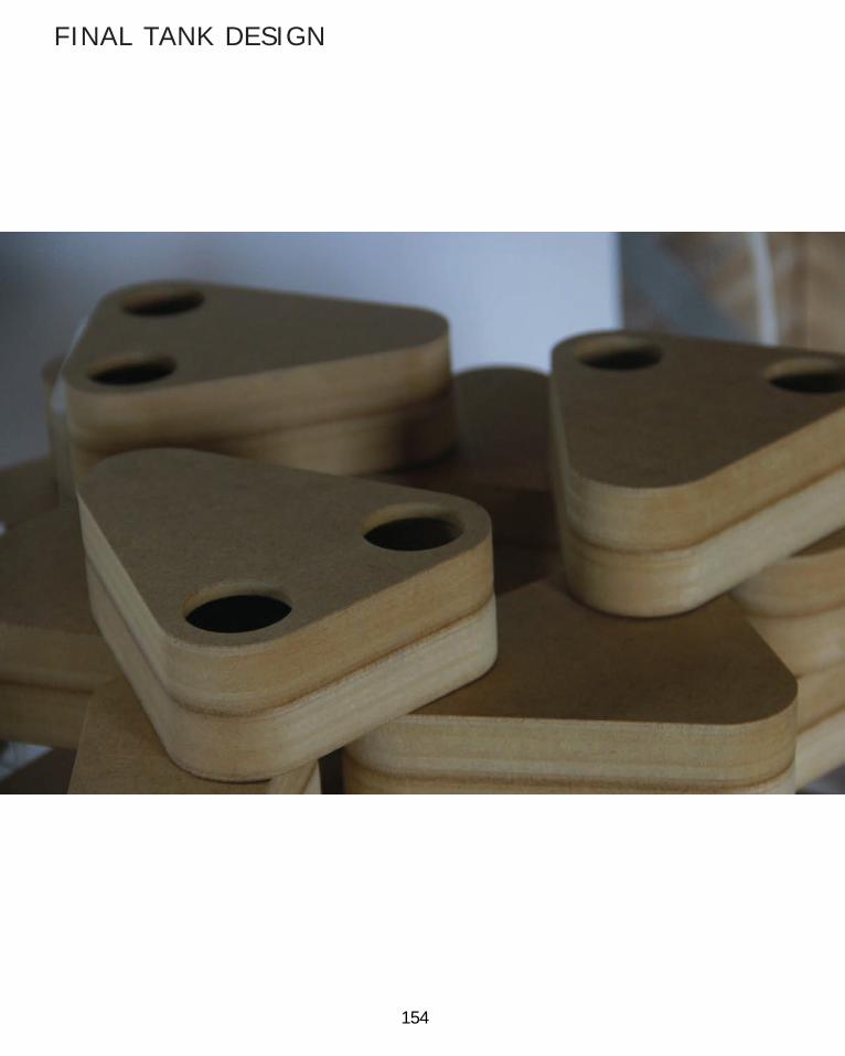
154
FINAL TANK DESIGN

155
C.3 FINAL DETAIL MODEL

156
FINAL TANK DESIGN

157
C.3 FINAL DETAIL MODEL

158
FINAL TANK DESIGN

159
C.3 FINAL DETAIL MODEL

160

161
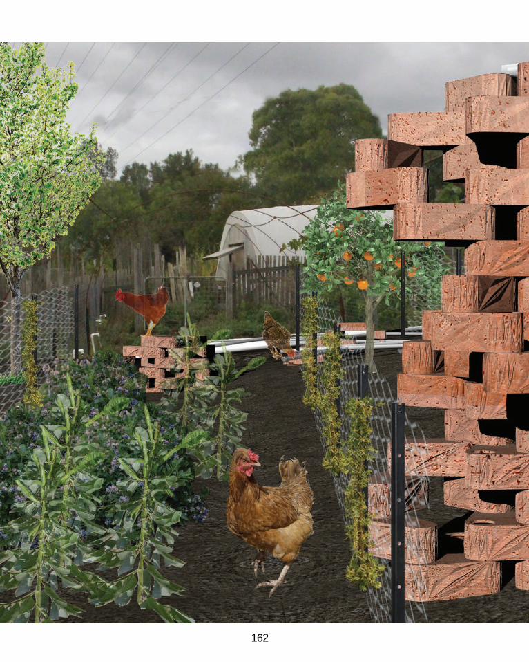
162

163

164
Compared to most of the subjects I have taken on at University, this course has been one of the most demanding yet rewarding of them. A lot is asked of us, and being able to fit it all in at a level that is to the best of my ability has been a real stretch, but in the end I feel I have gained alot in a short space of time because of it. What I personally feel most grateful for that has arisen from this undertaking is the introduction and in depth engagement with digital design concepts. It is interesting now to be at a level of understanding that when I see modern designs, I can not help but try and unravel the process behind it, and how such a form may have been conceived, generated, and constructed.
A large part of this understanding I feel has been aided by the hands on experience in grasshopper that is guided by this course. So much is covered in this course on grasshopper that I cant help but feel that I missed alot of it, or at least did not have time to let it all soak in, but regardless, the effort I did put in feels to have paid off. I’m excited to have a new tool at my expense that I can use to explore my ideas. If anything, if I had more time to explore more technique, I would have delved into some more serious coding to compliment my application of grasshopper. By the end of this course I feel like I was beginning to be frustrated by some of the limitations of grasshopper, or at
least at my lack in knowledge on know how most effectively use grasshopper to intelligently solve problems. And I think developing more of this algorithmic thinking from coding could do this, so that the algorithms I design can respond intelligently, not just ‘interestingly’. I dare to say that this course has made me want to explore that.
In terms of the learning objectives of this subject, I feel that it has effectively challanged how I interrogate a brief. It some ways I feel that this course has made me realise I can pin down alot more of the factors available than I could before, to allow the design to be streamlined and as well suited to its context as possible. In other ways though, it has made me realise that there is often more things of importance in a brief than specified, and developing forms that can go beyond these basic limitations can make the difference between good and great works. I feel this point is really explored through the surface manipulation techniques in this journal, and how they are in one sense unnecessary, they are in other all you really care about.
The techniques followed in this course have definitely given me the ability to easily and effectively generate variety for design possibilities, and test the way in which I evaluate and decide
CONCLUSION

165
between them. It is often not so straight forward or logical, as the analogy of ‘evolution’ used in this course to describe the process makes it out to seem, as considerations for design come from all kinds of directions, but this logic of thought is useful for understanding the process. I think the manner in which I explored the tank structure is a good example (albeit not perfect) of this non-linear evolution, where a design ‘evolutions’ can be forced from generated variation choices, conceptual perogatives such as ‘coherency’, or fabrication and material constraints, one I had to battle with alot.The structure of this course has also made me appreciate the need for accepting and utilising architectural discourse and precedent to selflessly advance the disipline by building upon the work of your predecessors. I think often we of creative disposition have this misguided perception that we need to be ‘unique’ or do it all ourselves for it to be worthy, when alot of the best design often comes from furthering an idea that someone else planted. By acknowledging that the people around you do fantastic work, and by honestly engaging with it and advancing it, all involved benefit and together we can reap the rewards. There is a slightly utilitarian thread in that, but that is not so much the focus. If I’m allowed to use my own project as an example, my water tanks can be an extention of the idea initiated by the project bloom, where complex
form is lead by the interactions of lots of individual elements. The extension in my design is trying to incorporate extra purpose to this process (in my case being able to store and utilise water) but maintain those qualities of freedom for interaction and form finding, addressible through both computer generation and human experimentation.
So to conclude, this subject has been a dense and enjoyable task, from which all my struggles have amounted to a greater and clearer readiness to partake in the realm of digital architecture.
C.4 LEARNING OBJECTIVES AND OUTCOMES

166
PART C REFERENCES
pg 85 - Jo/The Desert Echo, 2013, <http://www.thedesertecho.com/blog/food-forest-gardens-planting-guide/>pg 86 - Figure 1: http://maps.google.com.au/pg 86 - Figure 2: http://maps.google.com.au/pg 96 - Morgan, R.P.C., 2005, Soil Erosion + Conservation, Blackwell Publishing, pg 299pg 100 - Irrigation Australia Limited, 2008, YOUR GUIDE TO GOOD GARDEN WATERING,2nd edition written by Helen Moody, HortiMedia < http://irrigation.org.au/documents/bookshop/Guide_to_Good_Garden_Watering-Irrigation_Australia.pdf>pg 100 - Figure 1: Irrigation Australia Limited, 2008, YOUR GUIDE TO GOOD GARDEN WATERING,2nd edition written by Helen Moody, HortiMedia < http://irrigation.org.au/documents/bookshop/Guide_to_Good_Garden_Watering-Irrigation_Australia.pdf>pg 100 - Figure 2: Bereau of Meteorology, Annual Climate Report 2014, pg 13 < http://www.bom.gov.au/climate/annual_sum/2014/AnClimSum2014_LR1.0.pdf>pg 100 - Figure 3 Data from: Bereau of Meteorology, Annual Climate Report 2014, pg 14 < http://www.bom.gov.au/climate/annual_sum/2014/AnClimSum2014_LR1.0.pdf>pg 109 - Image 1: - http://designplaygrounds.com/wp-content/uploads/2012/08/BLOOM_02.jpgPg 109 - Image 2: http://www.bloom-thegame.com/main/wp-content/uploads/2012/07/THE-GAME3-pg 139 - Figure 1: https://www.google.com.au/url?sa=i&rct=j&q=&esrc=s&source=images&cd=&cad=rja&uact=8&ved=0CAcQjRxqFQoTCMOb2byKlMYCFSZjpgodwp8AeA&url=http%3A%2F%2Fwww.tiramisuzi.com%2Fevents%2Fslip-casting-workshop%2F&ei=sQSAVYP_AabGmQXCv4LABw&bvm=bv.96041959,d.dGY&psig=AFQjCNHh2sQpT4zNmMuT8egDGjD5fVailA&ust=1434539561134484

167
Special thanks to my tutor, FInn Warnock, for all his help and guidance over the course of this subject. I have learnt alot from you.
Thanks as well to my lovely group, in Claire, Tamsin, Trish and Charlotte, I couldn’t have got this far without all your help.
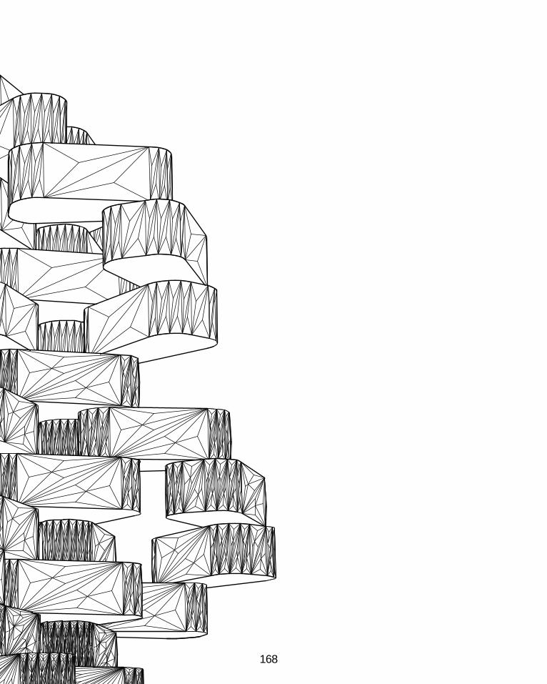
168