Embed Size (px)
Citation preview

GRADY HIGH SCHOOLADDITION & RENOVATIONS
FOR
ATLANTA PUBLIC SCHOOLS
SCHEMATIC DESIGN NARRATIVE
MAY 7 2019
CC PROJECT NUMBER 20180083
covertemplatesmall.indd 1covertemplatesmall.indd 1 5/3/2019 5:25:55 PM5/3/2019 5:25:55 PM


Grady High School | 0.3
TABLE OF CONTENTS
SECTION I CONTRIBUTORS DESIGN TEAM
SECTION II DESIGN INTRODUCTION
SECTION III SITE ANALYSIS
SECTION IV PROGRAM
SECTION V NARRATIVES
SECTION VI GRAPHICS
1.1 | Cooper Carry

Grady High School | 1.2
OWNER
Atlanta Public SchoolsPrimary Contact Danny Gutlay
DESIGN TEAM
ARCHITECT:
COOPER CARRY191 PEACHTREE STREET NE, SUITE 2400, ATLANTA, GA 30303-1770 TEL (404) 237-2000WWW.COOPERCARRY.COM
Managing Principal Robert A. Just / Cooper CarryProject Manager Sophia Tarkhan / Cooper CarryDesign Architect Megan Fagge / Cooper CarryProject Architect Katy Daugharty / Cooper Carry
Civil Theo Stone / Atwell Group
Structural J. Mac Wille / Wille Engineering
MEP Daniel Noto / RMF Engineering
Cost Es ma ng: Dan Ergle/ ADE Construc on Consultants
*Addi onal Consultants to be added a er full scope of work is determined.determine the appropriate repair procedures.
SECTION ICONTRIBUTORS (DESIGN TEAM)

2.1 | Cooper Carry

Grady High School | 2.2
DESIGN PHILOSOPHY
Cooper Carry is engaged in enhancing society’s quality of life through quality of design, both for its ability to function seamlessly, and to infl uence the spirit of each and every school user in a positve way. We believe that good design can inspire and we know there is a direct connection between the way we think and the way we learn. Students and teachers are most productive when they are inspired. With this in mind, we create environments that connect people and places, making the school a valuable part of the community. We call this connective design.
DESIGN NARRATIVE
Throughout preliminary meetings with APS, school offi cials, and multiple building surveys; we have prepared the attached report to document the existing conditions and proposed renovations and addition at Grady High School.
AdditionThe new addition is proposed at the corner of 10th Street and Charles Allen Drive in the approximate location of the current temporary classroom trailers.
The programming of the new addition has been developed to increase the capacity of the current school and provide GADOE compliant spaces for the CTAE programs. The addition will eliminate the need for portable classrooms.
Existing BuildingsGrady’s existing buildings vary in age of construction (1924-2005). Due to limited budget the extent of reno-vations will be limited. Prority will be given to Mechanical, Life Safety, and Water Infi ltration Issues. Roofs are between 13 and 23 years old and in need of replacement at Charles Allen Building, Performance Gym, and Auditorium. Remaining roofs are in need of repair. HVAC systems are nearing the end of their antici-pated lifespan and the custodial staff reports a signifi cant number of ongoing issues with the HVAC systems.
Depending on the cost of mandatory repairs we will also recommend upgrades to interior fi nishes, restrooms, and the renovation of selected spaces to compliment the proposed addition programming.
SECTION IIDESIGN INTRODUCTION
2.3 | Cooper Carry
CAPACITY AND REQUIREMENTS
School Address: Henry W. Grady High School 929 Charles Allen Dr. NE Atlanta, GA 30309
Grades: 9-12
Current Enrollment 2018-2019: 1375
Current Capacity as per GA DOE:Existing Building Full Time Equivilent (FTE) - 1275Instruction Units (IUs) - 68
Additional Classroom PortablesTemporary Classroom Trailers: 10 Classrooms adds 250 FTE in capacity
APS Calculates Capacity slightly differently than GA DOE by counting core classrooms:
Current Capacity as per APS: Core Classrooms without portables = 51 classrooms / 25 students per classroom = 1275
Proposed Capacity as per APS: Core Classrooms = 60 classrooms / 25 students per classroom = 1500 (Note that this calculation removes art classroms and counts PEC at 1/2 capacity) GA DOE calculations will include non core classrooms and FTE will be much higher.
Student Enrollment Projections as per APS: 2019-2020 1431 2020-2021 1450 2021-2022 1449 2022-2023 1461 2023-2024 1464

Grady High School | 2.4
Career Pathways and Specialty Programs
CTAE Pathways:1. Engineering and Technology - Proposed location - Addition2. Business, Management + Administration - Proposed location - Addition3. Fashion Marketing - Proposed location - Addition4. Sports + Entertainment Marketing - Proposed location - Addition5. Audio-Video Tech and Film - Proposed location - Existing Building6. Information Technology - Proposed location - Existing Building
The JROTC is housed in the stadium building which is not included in the scope of work for this program.
The Health Sciences and Graphic Communication programs are being phased out.
EXTERIOR ARCHTIECTURAL STYLE & HISTORIC PRESERVATION
Grady High School is a beautiful example of classical archtiecture. The oldest wing of the Charles Allen Building was built in 1923 with an addition in 1950. The Practice Gym was built in 1938. Both buildings have brick and stone detailing,some of which is very ornate, specifi cally the 12 decorative urns located on the parapets of the Charles Allen Building. This project includes an assessment of the existing facades and recommendations for repairs.
We have a responsibility to maintain the integrity of the existing buildings. The addition will compliment the existing architecture and help to connect the various buildings on site.

Grady High School | 3.1
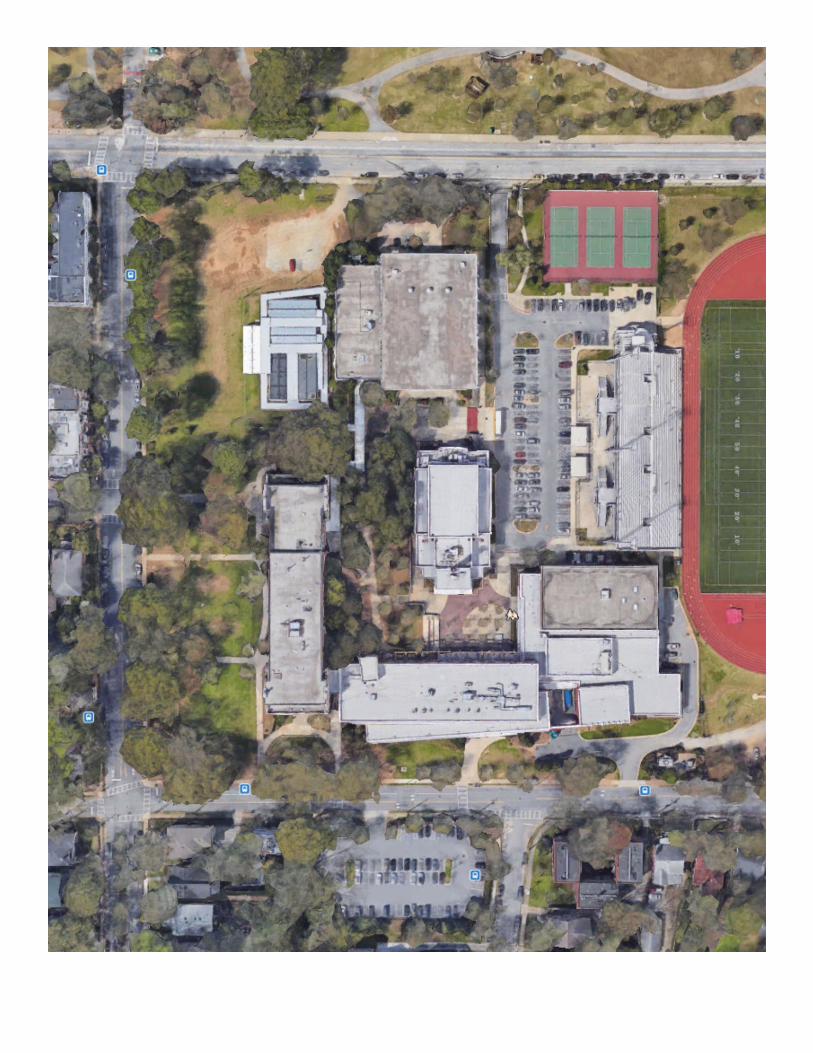
SECTION III. SITE ANALYSIS
The existing site is 19.5 acres including the large stadium. There is a small staff parking lot on the south side of 8th street. Grades on site vary from the high point at the NW corner to the low point (approximately 30’ lower at the stadium. There are signifi cant grade changes throughout the site. Piedmont Park is directly north of the site. There are residential neighborhoods to the west and south. Restaurants, retail, and access to the beltline are on the east side of the site across from Monroe Drive. The school address is 929 Charles Allen Drive.
A. Context Map

3.2 | Cooper Carry
B. Parking Findings:
Three existing lots were created in 2004 and are in fair to good condition.
The APS standards for minimum parking at high schools are: One Space for each Staff person plus 25 visitor spaces and one parking space for every 2.5 students
Required Parking at Grady High school:Staff Parking (Projected) = 127 SpacesVisitor Parking: 25 SpacesStudent Parking (Projected) = 1350 students / 2.5 = 540 parking spacesTotal Spaces as per APS standards = 692 parking spaces
Existing Parking at Grady High school:A. Stadium Lot 1= 99 Spaces (includes 5 HC Spaces)B. 8th Street Lot 2 = 71 Spaces (includes 5 HC Spaces)C. Performance Gym Lot = 4 Spaces (included 2 HC Spaces)Total Existing Spaces = 174 parking spaces
Parking Recommendations:
Proposed New Parking at Grady High school:D. Pave existing gravel lot at corner of 10th Street and Charles Allen Drive = 76 Spaces (32,800 sf)E. Add New Visitors Lot at front of Charles Allen Building = 50 spaces (17, 500 sf)Total New Spaces = approximately 126 parking spaces
Total Proposed + Existing Parking = approximately 300 spaces
The exact number of spaces will be determined by the fi nal design of the addition and the loca-tion of the temporary classroom trailers.
Existing fl agpole and pencil sculpture are located in the area of proposed parking at the Charles Allen lawn. Flagpole is to be relocated to better mark the entrance. Pencil sculpture is to be relocated to a new location. A new fl agpole will be located at the entrance to the building.
Challenges:• New paving will be located to avoid existing large trees on site. The removal of some trees is
required As per 2004 survey this would include approximately 10 small maples and birch trees located at the center of the lawn. Removals will have to be coordinated with the parks department. Additional trees will need to be planted on site to make up for removals.
• The UDC and community may object to adding parking in front of the Charles Allen Building. • The additional paving will count as an impervious surface. City watershed will require additional
water retention on site to make up for the added impervious material (see stormwater recommenda-tions).
• The total number of parking spaces will still be less than the minimum per district standards, how-ever, students and staff are already accustomed to parking shortages. The site is easily accessed by pedestrians and bikes and alternate modes of transportation are encouraged. The addition does not drastically increase the student population, while new parking does not meet district standards it still provides additional parking that will help reduce the overall shortage.

Grady High School | 3.3
AREA OF PROPOSED ADDITION
AREA OF PROPOSED
PARKING
AREA OF PROPOSED
VISITORPARKING
EXISTING STADIUM LOT (99 SPACES)
EXISTINGPERF. GYM LOT
(4 SPACES)
EXISTING 8TH STREET LOT (71 SPACES)
3.4 | Cooper Carry
Grady High School | 3.5

3.6 | Cooper Carry
C. Stormwater / Sewer Findings:
• Storm water management - As per the city watershed department, the fi rst 1” of rainfall at all new im-pervious area must be retained and infi ltrated on site. Options for managing this water are sub-surface structures (pipes, vaults, or chambers), cisterns, water towers, green roofs, and pervious pavement systems. Depending on on-site soil conditions and the surrounding storm water infrastructure if may be possible to attempt to do a combination of infi ltration and detention storage in open areas around the new building. A green roof if installed would potentially reduce or remove the detention requirement.
• Sewer - There is an existing 78” trunk sewer located along the western portion of the property.
Stormwater / Sewer Recommendations:
• Recommendations are based on the current understanding of the site and existing documentation. Recommendations may change due to meetings with the city, survey results, geotech reports, or design direction.
• Provide an underground detention structure to address the proposed impervious area to be added, re-search feasiblity of other options. The school currently has an apiary on one of the roofs of the Charles Allen Building. It is possible that a green roof on the new addition could be used by the school while also reducing the requirement for on site retentention.
• Build over the trunk sewer in a similar way that was done at the 8th street building. Civil engineers and APS lawyers will work with city of Atlanta to fi nalize the encroachment agreement for building over the trunk sewer line.
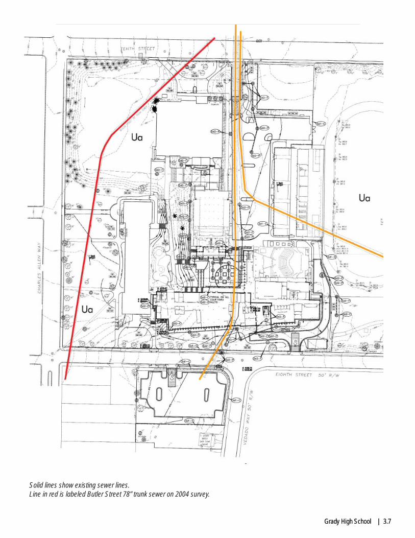
Grady High School | 3.7Grady High School | 3.7
Solid lines show existing sewer lines. Line in red is labeled Butler Street 78” trunk sewer on 2004 survey.

3.8 | Cooper Carry
D. Courtyards Findings:
Existing Courtyards (Drainage / Washouts)The existing interior courtyards are showing signs of erosion due to the lack of vegetative ground cover. The building and trees limit the opportunity for the ground cover to grow leading to the areas of exposed earth and washout. There also appears to be pockets of settlement in the open courtyard with the commemora-tive bricks. There are areas of ponding mud and water at the stepped concrete seating adjacent to the brick paver. The custodian reported that the washout causes extremely slippery areas of the site as well as prob-lems with kids tracking mud into the building.
Courtyard Recommendations:
At planted areas we recommend low maintenance / low light materials (i.e. mulch, river rock, etc.) to be placed in these areas after regrading. Pruning of exisitng vegetation and tree trimming is also recom-mended. This will allow sunlight to reach the new planted materials. Depending on available budget for landscaping we may recommend additional improvements in these areas.
At existing hard surfaced areas, repair brick pavers by resetting all loose pavers. Allow for partial replace-ment. Replace all damaged / sunken sidewalks. Resurface stepped seating.

Grady High School | 3.9
3.10 | Cooper Carry
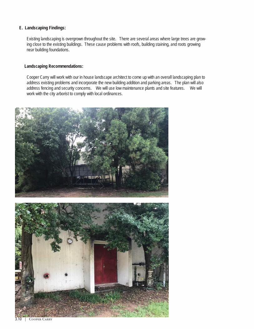
E. Landscaping Findings:
Existing landscaping is overgrown throughout the site. There are several areas where large trees are grow-ing close to the existing buildings. These cause problems with roofs, building staining, and roots growing near building foundations.
Landscaping Recommendations:
Cooper Carry will work with our in house landscape architect to come up with an overall landscaping plan to address existing problems and incorporate the new building addition and parking areas. The plan will also address fencing and security concerns. We will use low maintenance plants and site features. We will work with the city arborist to comply with local ordinances.

Grady High School | 3.11
F. Entrance Findings:
The existing main entrance on Charles Allen Drive is not dominant and visitors often enter from 10th street or 8th street when trying to fi nd the front offi ce. The stone gateway entrance on 10th street causes further confusion as visitors assume this is a main entrance.
Entrance Recommendations:
The proposed addition includes an entrance plaza to the north of the current entrance. The plaza would emphasize the main entrance and provide an ADA ramp near the new visitor parking. A new monumental sign and exterior lighting will also emphasize the new plaza.
The existing arch on 10th street could potentially be relocated. The curb cut into the stadium parking lot could also be gated to discourage visitors from entering here. Additional discussions with APS and school representatives are required to determine the best approach for site security.

3.12 | Cooper Carry
G. Additional Site Work:
• Bike Parking was recently installed adjacent to the student parking lot next to the auditorium. • School requested that project include repair of the paving adjacent to the Practice Gym. • School has requested gates between practice gym and the adjacent auditorium and performance
courtyards in order to secure the existing courtyards.
Additional Site Recommendations
• Additional bike parking can be added if school reports that existing bike parking is not suffi cient. • Area adjacent to practice gym can be paved or landscaped. • Site security: It is feasible to gate off the existing courtyards, however these areas will require emer-
gency egress gates since many of the buildings exit into the courtyards.

Grady High School | 3.13
H. Proposed Site Plan:
See graphics section of the report.

3.14 | Cooper Carry
BOYS’ HIGH SCHOOL POST CARD - 1926
SITE AERIAL SURVEY - 1949, PRIOR TO 1950 ADDITION

Grady High School | 4.2
INTRODUCTION
Grady High School was last renovated between 2003 and 2005. The school currently has 10 modular class-room units. Multiple CTAE programs have been added to the school curriculum since the last renovation. Current spaces are inadequate for some of the proposed uses. The school reports that the cafeteria and media center are both overcrowded during peak use.
Through multiple discussions and meetings with the school the program below has been developed.
ANTICIPATED PROGRAM NEW ADDITION SPACE:• Ten (10) Additional Core Classrooms - minimum square footage 750sf each• CTAE space for Engineering and Technology - minimum square footage 2990 sf• CTAE space for Business, Management, Administration - minimum square footage 1310 sf• CTAE space for Fashion Marketing - minimum square footage 1385 sf• CTAE space for Sports + Entertainment Marketing - minimum square footage 1385sf• Additional Administration space is required for counseling and / or administration• Additional student support spaces, commons areas, school store.• Media Center large enough to serve proposed student capacity - minimum square footage 5700 sf• Two (2) Additional Science Labs - minimum square footage 1000 sf each
CONVERSION / RENOVATION OF EXISTING SPACE:The existing media center and information technology lab in the ground fl oor of the 8th Street Building will be renovated and reconfi gured. Work will include:• Expansion of the existing cafeteria• CTAE space for Information Technology Lab - minimum square footage 1310 sf• Lecture Hall type space for large classes and testing• Existing Graphic Design and Print space will be used as an art classroom.
The program has been coordinated with the Atlanta Public Schools to meet or exceed requirements of the Georgia Department of Education Standards and guidelines both in quantity and square footage.
SECTION IVPROGRAM

4.3 | Cooper Carry
PROGRAM TABULAR SUMMARY
Spaces proposed at Addition:

Grady High School | 4.4

5.1 | Cooper Carry

Grady High School | 5.2
A. ARCHITECTURAL
1. General
The design of the Grady High School Addition will promote pride of place and the interaction of students and teachers both in the building and around the site. The new addition will be approximately 61,000 square feet. The campus capacity after completion of the addition will be 1500 students.
The design will conform to requirements found in the APS Design Guidelines. The design will follow Georgia Department of Education Facilities Services State Board of Education Rules.
The design will comply with all applicable federal, state, and local building codes: International Building Code Life Safety Code (NFPA 101) Americans with Disabilities Act Accessibility Guidelines International Energy Conservation Code
The architectural design is divided into two sections:
• Addition - Construction of a new 61,000 sf school addition to serve the programing listed on the previous pages. See graphic pages for proposed plans. The addition will span over the existing trunk sewer on site. Some excavation will be required at the ground level due to the existing grades. The building will include one elevator, 2 stairwells, and multiple restrooms on each fl oor.
• Renovation - Work includes roofi ng replacement, exterior repairs, selective interior renovations and MEP upgrades. • Existing Cafeteria, administration, and health occupation labs are slated to be renovated. • Existing auditorium and performance gym lobby will have a higher level of renovation than remaining
areas of the school. • Exterior Upgrades include roofi ng replacement and roofi ng repair.• Exterior Facade Repairs include repair of historic masonry at Charles Allen Building and the Practice
Gym. • Selective replacement of exterior doors. • Interior repairs include replacement of carpet, painting of walls, selective ceiling replacement• Replacement of fl ooring, fi xtures, and stalls at student and staff restrooms. • Replacement of interior signage. • See narrative for MEP and LVES for more information.
SECTION VNARRATIVES
5.3 | Cooper Carry
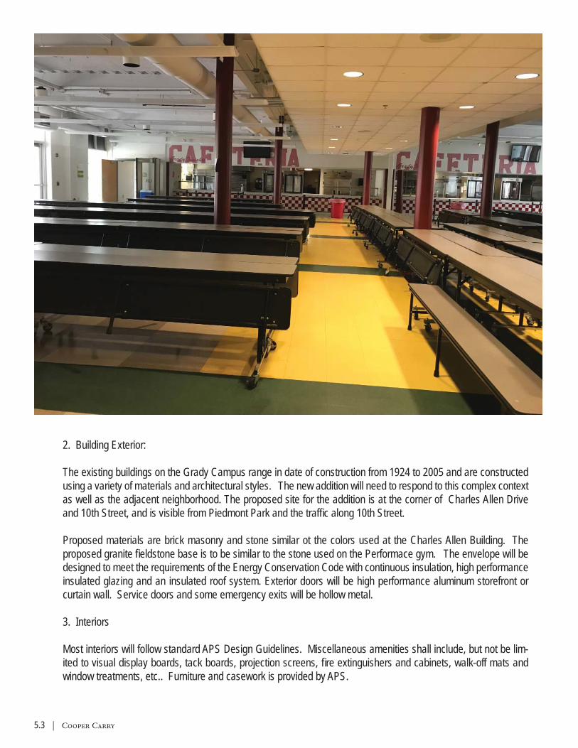
2. Building Exterior:
The existing buildings on the Grady Campus range in date of construction from 1924 to 2005 and are constructed using a variety of materials and architectural styles. The new addition will need to respond to this complex context as well as the adjacent neighborhood. The proposed site for the addition is at the corner of Charles Allen Drive and 10th Street, and is visible from Piedmont Park and the traffi c along 10th Street.
Proposed materials are brick masonry and stone similar ot the colors used at the Charles Allen Building. The proposed granite fi eldstone base is to be similar to the stone used on the Performace gym. The envelope will be designed to meet the requirements of the Energy Conservation Code with continuous insulation, high performance insulated glazing and an insulated roof system. Exterior doors will be high performance aluminum storefront or curtain wall. Service doors and some emergency exits will be hollow metal.
3. Interiors
Most interiors will follow standard APS Design Guidelines. Miscellaneous amenities shall include, but not be lim-ited to visual display boards, tack boards, projection screens, fi re extinguishers and cabinets, walk-off mats and window treatments, etc.. Furniture and casework is provided by APS.

Grady High School | 5.4
3. Interiors (Cont.)
A. Typical Classroom Finishes: a. Walls and Partitions are to be painted concrete masonry block. b. Floors: VCT with rubber base, two color pattern. c. Ceilings: 2x2 acoustic ceiling panel set in exposed prefi nished metal grid. d. Doors: Solid core wood door set in steel door frame.
B. Media Center Finishes: a. Walls and Partitions are to be painted concrete masonry block. b. Floors: Carpet with rubber base. c. Ceilings: 2x2 acoustic ceiling panel set in exposed prefi nished metal grid. d. Doors: Solid core wood door set in steel door frame.
C. Existing Cafeteria to be expanded: a. Walls and Partitions are to be painted concrete masonry block. b. Floors: VCT with rubber base, two color pattern. c. Ceilings: Existing ceiling has 2x2 acoustic ceiling panel set in clouds with partially exposed painted metal grid above. d. Doors: Solid core wood door set in steel door frame.
D. Public Corridors: a. Walls and Partitions are to be painted concrete masonry block. b. Floors: VCT with rubber base, multi-color pattern.
E. Student Restrooms: a. Walls and Partitions: Concrete Masrony block painted. b. Floors: Epoxy Resin c. Ceilings: Gypsum board ceiling d. Toilet Partitions: Solid Plastic
F. Staff Restrooms: a. Walls and Partitions: Gypsum board with ceramic tile base and 6’ wainscoat. b. Floors: Epoxy Resin c. Ceilings: Gypsum board ceiling G. Administration: a. Walls and Partitions: Gypsum board painted. b. Floors: Carpet with rubber base. c. Ceiling: 2x2 acoustic ceiling panel set in exposed prefi nished metal grid.

5.5 | Cooper Carry
B. STRUCTURAL Prepared by Willett Engineering A. General Overview
The Grady High School expansion will consist of a new four-level classroom addition added between the Charles Allen Building and the Performance Gym.
B. Design ApproachThis building is being positioned adjacent to an existing building which will require a pedestrian bridge to link the two buildings.
The fl oor framing will consist of a 5-inch concrete slab supported on a galvanized metal deck. The metal deck will be supported on structural steel beams spaced at 72 inches on center and will span from the column lines at the exterior walls to the column lines located at the interior corridor walls.
The roof framing will consist of a 1 ½ inch deep metal deck supported on K-Series bar joists spaced at six feet on center. The bar joists will be supported by structural steel beams spanning perpendicular to the bar joists. The bar joists will span from the column lines at the exterior walls to the column lines located at the interior cor-ridor walls.
The building columns will be structural tube members.The lateral loads (wind, seismic) will be resisted by structural steel braced frames.
After the preliminary design is prepared and reviewed with the design team, the building will be designed and modeled in a three-dimensional software (RISA.) The Revit software will be used to coordinate with the design team and produce detailed drawings. During the design process, we will hold internal design reviews as well as collaborative meetings with the entire design team. Prior to submitting the drawings for bid, the project will be reviewed by a senior project manager for quality control.
C. Design Criteria1. Applicable Codes:
a. IBC 2012 w/ Georgia Amendmentsb. AISC LRFD Specifi cation, 14th Editionc. ACI 318-11
2. Live Loads:a. Lobbies and Corridors 100 psfb. Classrooms 40 psfc. Roof 20 psf
3. Superimposed Dead Loads:a. MEP, Ceilings, and Misc. 10 psf
4. Snow Load Criteria:a. Flat Roof Snow Load 5 psfb. Importance Factor 1.1c. Exposure Factor 1.0
Grady High School | 5.6
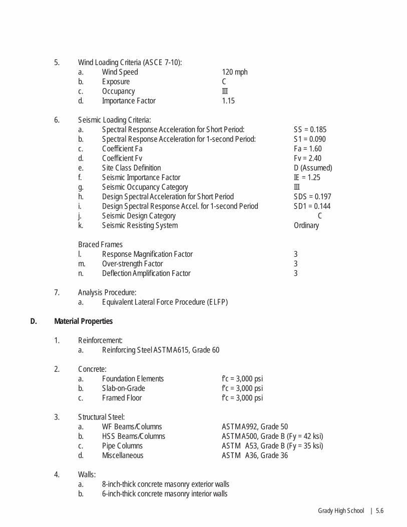
5. Wind Loading Criteria (ASCE 7-10):a. Wind Speed 120 mphb. Exposure Cc. Occupancy IIId. Importance Factor 1.15
6. Seismic Loading Criteria:a. Spectral Response Acceleration for Short Period: SS = 0.185b. Spectral Response Acceleration for 1-second Period: S1 = 0.090c. Coeffi cient Fa Fa = 1.60d. Coeffi cient Fv Fv = 2.40e. Site Class Defi nition D (Assumed)f. Seismic Importance Factor IE = 1.25 g. Seismic Occupancy Category IIIh. Design Spectral Acceleration for Short Period SDS = 0.197i. Design Spectral Response Accel. for 1-second Period SD1 = 0.144j. Seismic Design Category Ck. Seismic Resisting System Ordinary
Braced Frames l. Response Magnifi cation Factor 3m. Over-strength Factor 3n. Defl ection Amplifi cation Factor 3
7. Analysis Procedure:a. Equivalent Lateral Force Procedure (ELFP)
D. Material Properties
1. Reinforcement:a. Reinforcing Steel ASTM A615, Grade 60
2. Concrete:a. Foundation Elements f’c = 3,000 psib. Slab-on-Grade f’c = 3,000 psic. Framed Floor f’c = 3,000 psi
3. Structural Steel:a. WF Beams/Columns ASTM A992, Grade 50b. HSS Beams/Columns ASTM A500, Grade B (Fy = 42 ksi)c. Pipe Columns ASTM A53, Grade B (Fy = 35 ksi)d. Miscellaneous ASTM A36, Grade 36
4. Walls:a. 8-inch-thick concrete masonry exterior wallsb. 6-inch-thick concrete masonry interior walls

5.7 | Cooper Carry
STRUCTURAL DESIGN NARRATIVE (CONT.)
E. Foundations
1. Geotechnical Report:a. A Geotechnical Report has not yet been provided to date. Based on the existing construction type and the relatively light foundation loads, we anticipate that spread foundations will be used.
2. Foundations:a. The building columns will be founded on conventional shallow concrete footings and the perim-eter walls, with the exception of the concrete retaining wall, will be supported by a 2’-6” wide x 12” thick continuous strip footings.b. Slab-on-grade is typically expected to be 4 inches thick and reinforced with WWF 6x6-W1.4xW1.4.
F. Structural Lateral Load Resisting System
1. Lateral System:a. The lateral system is anticipated to be ordinary structural steel braced frames.
2. Expansion Joint:a. An expansion joint is anticipated between the new bridge structure and the new classroom expansion.
G. Columns
1. The building columns are expected to consist of W8x40 members.
H. Roof Framing System
1. The roofs will consist of open-web K-Series steel bar joists spaced at 6’-0” on-center with a metal deck supported by structural steel beams.2. It is anticipated the roof will be drained by interior roof drains.
I. Floor Framing System
1. The fl oor will consist of structural steel beams spaced at 6’-0” on-center with a5-inch-thick concrete slab on a 1½”-deep metal deck supported by steel beams.Structural steel beams will be located directly below the interior masonry walls.
J. Retaining Wall
1. The rear wall of the building will be below grade from the fi rst fl oor to the basement level, and the wall will be a conventional 16”-inch thick concrete cast-in-place wall.

Grady High School | 5.8
C. MECHANICAL, ELECTRICAL, PLUMBING Prepared by RMF EngineeringGeneral Overview
This document summarizes the fi re protection, plumbing, and mechanical process systems for the APS Grady High School project. The narrative provides the Basis of Design and understanding of the Owner’s Design Intent for the fi re protection, plumbing and mechanical systems. As such, the document can begin to be used to develop a construction cost model/budget with associated general requirements for the facility.
This document establishes the basic design criteria for the fi re protection, plumbing and mechanical systems for the proposed project and shall be used to supplement local, state and national codes and laws which are applicable to the work being undertaken and those laws dealing with environmental protection, occupational safety and health.
System selection, sizing and loads are based on the best information available at the time the documents were produced, which currently includes programmatic and associated square footage information. Necessary adjustments to the project documents will be made as the design process continues and more information, such as block and stacking diagrams, are received. The new building size is unknown however an estimate of 60,000 GSF was used for this narrative
Infrastructure and Utility Systems
• Engineers will refer to the site and civil documents for information regarding the site utilities. The project will require domestic water, sanitary sewer, storm drainage and natural gas services.
• The infrastructure and utility systems will be sized to serve the project as currently defi ned with approxi-mately 5-10% additional capacity to accommodate future renovations and program changes.
• The building will be provided with a ground level mechanical room.• The fi rst fl oor equipment room will serve as the incoming utility entrance point. The room will contain the
fi re and domestic water entrance and backfl ow prevention equipment, the domestic hot water heating sys-tem for the building and the domestic water booster pump if required.
Division 21 - FIRE PROTECTION 21.1. Design Criteria
• Building Hazard Classifi cationThe building is not classifi ed as a high-rise structure since there are no occupied fl oors more than 75 feet above the lowest level of fi re department vehicle access.
• Sprinkler System Criteria1. The requirements of the IBC 2012 Section 903 require an automatic sprinkler system to be in-
stalled in the building based on the defi ned occupancy and building height. The building shall be protected with a wet pipe sprinkler system.
2. Sprinkler system shall conform to requirements stated in NFPA 13. Sprinkler systems require-ments are defi ned in Chapter 7 and installation requirements are defi ned in Chapter 8 for wet and dry pipe systems in the building. Based on these requirements, hydraulically calculated sprinkler piping and sprinkler heads will be provided at a minimum frequency such that the protection area does not exceed 225 per square feet per head per Chapter 8 of NFPA 13.
5.9 | Cooper Carry
MEP DESIGN NARRATIVE (CONT.)
21.1. Design Criteria (continued)
• Sprinkler System Criteria (continued)3. Various areas shall be sprinklered to the following densities calculated from the density curves in NFPA Standard 13, with a minimum area of application of 1,500 square feet:
• Light Hazard areas such as classrooms, multipurpose, offi ce areas, public a• reas, corridors and lobbies will have a minimum design density of 0.10 gallons per minute per
square foot over the hydraulically most remote 1,500 square feet.• Ordinary Hazard Group I areas such as the storage rooms, mechanical rooms, electrical switch-
gear, and transfer rooms will have a minimum design density of 0.15 gallons per minute per square foot over the hydraulically most remote 1,500 square feet.
• The design calculations shall include an allowance for outside hose streams and a ten (10) pound per square inch safety factor for future water supply deterioration.
• Standpipe Criteria1. The requirements of the IBC 2012 Section 905 may require a standpipe system to be installed
in the building based on the defi ned occupancy and current building height therefore one will be designed for the building.
2. The highest fl oor of the building is assumed to be more than thirty (30) feet above the highest level of fi re department access. Should the highest fl oor be lower than thirty (30) feet above the highest level of fi re department access a standpipe system will not be required.
3. A manual wet standpipe system shall be provided. Standpipe system shall conform to require-ments stated in NFPA 14. A manual wet standpipe system is a wet standpipe system connected to a small water supply for the purpose of maintaining water within the system or sharing a water supply with an automatic sprinkler system, but not having a water supply capable of delivering the system demand attached to the system. The system demand is left for when the pumper truck arrives on-site.
4. Required top of riser standpipe fl ow and pressure requirements (500 gpm @ 100 psi for the most hydraulically remote standpipe) shall be provided by the fi re department pumper truck.
• Fire Pump Criteria1. It is assumed that a fi re pump will not be required.
21.2. Fire Suppression Systems
1. A dedicated eight (8) inch fi re protection service, separate from the domestic water service, will be brought into the building. The fi re service shall have a double detector check assembly and alarm valve located in the 1st fl oor riser room.
2. A post-mounted fi re department Siamese connection shall be located at the exterior of the building.
Grady High School | 5.10
3. Sprinklers• The building will be fully sprinkled by an automatic wet sprinkler system. The entire system
shall be in accordance with NFPA 13 and shall meet all requirements of State and local authori-ties having jurisdiction and the Owner’s Insurance Underwriter. Ordinary temperature–rated sprinklers shall be used throughout the building.
• Sprinklers shall be installed at the top of each stairwell and under the fi rst accessible landing above the bottom of the shaft.
• Sprinkler piping for the automatic wet pipe system will extend from a sprinkler riser. Each sprin-kler zone will be provided with a zone valve assembly connected to the sprinkler riser.
• Sprinkler head layout will conform to the requirements of NFPA 13. Fully recessed quick response sprinklers will be provided in all hard ceiling areas with custom cover plates to match the ceiling paint color. Semi-recessed quick response sprinklers will be provided in all sus-pended acoustical tile areas with chrome escutcheon plates. Upright quick response brass pendants will be provided in mechanical areas, and areas without ceilings. Sprinklers installed in mechanical equipment rooms, electrical equipment rooms, and main switchgear rooms will be provided with protective head covers.
4. Standpipes• Class I systems shall be provided with 2-1⁄2 in. inch fi re department valves having 2-1/2 inch
by 1-1/2 inch reducers, cap, and chain in the following locations:• At the highest intermediate landing between fl oor levels in every required exit stairway.• At the highest landing of stairways with stairway access to a roof, and on roofs with a slope of
less than 3 in 12 where stairways do not access the roof.• At the hydraulically most remote portion of the system to facilitate testing.• Each standpipe will be minimum six (6) inch diameter and will be provided with a 2-½ inch
sprinkler zone valve assembly at every fl oor for service to the sprinkler system. • Each zone valve assembly will be provided with a fl ow switch, check valve and zone control
valve, a 2-½ inch vertical drain will be provided in each stair tower of the building addition. Flow switch test drains will be connected to the vertical drain at every fl oor.
• Each hose connection on the manual standpipe system shall be provided with a conspicuous sign that reads “MANUAL STANDPIPE FOR FIRE DEPARTMENT USE ONLY.”
21.3. Specialty Systems
1. A dry pipe sprinkler zone will be provided for the following areas of the building. These areas will be provided with a dedicated zone valve capable of separating the wet side from the dry side consisting of unfi lled sprinkler piping distributed over the parking areas. This zone valve will be controlled by dry pipe control valve and release air in system to allow water fl ow during sprinkler head operation. Water fl ow alarm will also be provided with system.
a. Exterior loading/unloadingb. Main electrical room
2. Clean Agent Fire Suppression SystemsThe current program for the project does not identify areas that will require a special fi re protection system similar to an FM-200, halon or CO2 tank system.
3. Building Smoke ControlIn accordance with IBC 2012, the building does not require an active smoke control, stair pressuriza-tion or smoke evacuation system.
5.11 | Cooper Carry
MEP DESIGN NARRATIVE (CONT.)
DIVISION 22 - PLUMBING22.1 DESIGN CRITERIA
A. All plumbing and piping work shall be executed in the proposed facility in accordance with local, state and national codes and laws applicable to the work being undertaken. Plumbing systems for the facility include domestic, sanitary, storm and natural gas systems to support the various program functions.
22.2 PLUMBING SYSTEMSA. Domestic (Potable) Water System
1. Domestic water serving the facility will be provided to satisfy the maximum probable demand of the domestic water system. Code minimum water supply fi xture units or actual equipment water consumption fl ow rates will be used to determine domestic water quantities and appropriately size the piping.2. A 3-inch water service will enter the fi rst fl oor mechanical room to serve the domestic water system. 3. It is assumed that the available water pressure is suffi cient to serve the building therefore a booster pump package will not be required to maintain required domestic water system pressure for the building.4. Piping distribution for the domestic cold water will originate in the fi rst fl oor mechanical room and branch to the building hot water systems. The piping will be routed above the ceiling. Pipe lines serving toilet groups will be provided with isolation valves and water hammer arrestors near end of runs. Tepid water will be provided to any safety devices.
B. Service Water Heating1. Domestic hot water will be generated at 140°F by a single tank type gas-fi red domestic hot water heater. Basis of design shall be PVI Conquest.2. Alternate: Building domestic hot water will be generated at 130°F by a single electric tank type domestic hot water heater. The 130°F water will be tempered down to 110°F supply temperature using Holby tempering valves. The basis of design shall be State PCE.3. To avoid control problems associated with oversized single thermostatic mixing valves, a dual mixing valve arrangement will be provided to temper the 140°F water down to 130°F supply tempera-ture. The system will have a piped recirculation system to maintain minimum 110°F hot water supply temperature at all times. The basis of design for the dual mixing valve is the Leonard New Generation High-Low System.4. Domestic hot water quantities will be estimated by potable fi xture counts and code required fi xture units for water.

Grady High School | 5.12
C. Plumbing Fixtures1. Plumbing fi xtures in public toilets in the building will be coordinated with architectural consider-ations and be constructed of vitreous china or a fi xture of similar quality.2. Plumbing fi xtures will be provided where indicated on the architectural drawings. All plumb-ing fi xtures shall be low fl ow, commercial grade of type, style and material consistent with the intended use. Concealed manual controls will be used on all fi xtures where practical. Plumbing fi xtures will generally be as follows:
a. Water closets – Vitreous China, elongated, wall mounted, top spud, fl ush valve, open front seat.b. Urinals – Vitreous China, wall mounted, top spud, fl ush valve.c. Lavatories - Vitreous China, wall or counter mounted with metering faucet.d. Showers – ADA approved, one-piece gel coat insert, pressure-balancing mixing valve with lever handle and integral volume control. Wall/hand shower with in-line vacuum breaker, fl exible 5’ metal hose, wall connection and fl ange, 30” slide bar for hand shower mounting.e. Sinks – stainless steel, counter mounted with gooseneck faucets and wrist blade handlesf. Mop basin – molded stone or terrazzo.g. Plumbing brass – Chicago faucets, Sloan fl ush valves, type as required.
3. Water fountains – Barrier-free dual height, wall mounted self-contained electric water cooler with stainless steel cabinet and bottle fi ller.4. Water-Conserving Fixtures: Plumbing fi xtures and fi ttings shall use in aggregate at least 30% less water than the water use baseline calculated for the building after meeting the Energy Policy Act of 1992 fi xture performance requirements. Flow and fl ush rates shall not exceed the following:
a. Toilets: no more than 1.28 gallons per fl ush and have documented bowl evacuation capability per MaP testing of at least 400 grams.b. Urinals: no more than 0.125 gallons per fl ush or use.c. Lavatory Faucets: 0.5 gpm with metering faucet controls.
5. Isolation valves shall be provided above the ceiling for each toilet room/bathroom group. 6. Water hammer arrestors shall be provided for each toilet/urinal with a fl ush valve.7. Non-freeze wall hydrants shall be located around the perimeter of the building, one (1) per exposure or one (1) per 100 linear feet, whichever is greater, for landscape use and shall be supplied from the domestic water system.
D. Elevator Sump Pump1. The pump and oil sensor technology control system shall comply with ASME A17.1-2010 stan-dard. The system shall function automatically to remove water from the elevator pit while containing oil without any human intervention. 2. Elevator sump pump and oil-minder control and alarm system shall be Stancor SE or Liberty ELV oil minder control and alarm system, and shall consist of centrifugal pump, motor, fl oat assemblies, oil-sensor probe, starters, J-box, wiring and complete automatic controls

5.13 | Cooper Carry
MEP DESIGN NARRATIVE (CONT.) DIVISION 22 - PLUMBING22.2 PLUMBING SYSTEMS (CONT.)
E. Sanitary and Vent System
1. Sanitary drainage piping will be routed from the plumbing fi xtures to vertical pipe risers then be collected horizontally below the building and discharge by gravity to the site sanitary sewer. Cleanouts shall be provided in accordance with the International Plumbing Code.2. Plumbing code drainage fi xture units will be used to determine the sanitary system load and pipe sizes.3. Floor drains will be provided in all mechanical rooms, custodial rooms, at water coolers, and in toilet rooms and shall be piped to the building sanitary system. 4. Floor drains in toilet rooms shall utilize trap primers. Floor drains in mechanical rooms shall utilize trap guards in lieu of trap primers.5. An oil minder sump pump shall be provided for each elevator pit to comply with ASME A17.1 - 2010 - Safety Code for Elevators and Escalators.
F. Storm Drainage1. Generally, storm water for the building will be collected via sloped roofs, gutters, vertical down-spouts. Connection to the site storm water system will be direct with downspout boots.2. For building areas with fl at roofs, the drainage system shall utilize commercially available drains of style, size, and quantity consistent with the area being drained. The piping shall be routed from the roof drains to vertical pipe risers then be collected horizontally below the building and dis-charge by gravity to the site storm sewer. 3. Where a fl at roof is utilized and roof scuppers are not used for emergency overfl ow, a second-ary roof drain system will be provided. Discharge shall be above grade, in a location which would normally be observed by the building occupants or maintenance personnel.4. Sizing of the roof drains and piping shall be based on a rainfall rate of 3.7 inches per hour for a storm of one (1) hour duration and 100-year return. 5. Storm drain piping shall be the same materials as those described for the sanitary drainage system. Cleanouts shall be provided in accordance with the plumbing code.
G. Natural Gas1. A new natural gas service will be provided as the combustion fuel for the building domestic hot water heaters. Pressure reduction and metering will occur on the exterior of the building and shall be obtained and provided by the utility provider. Natural gas service will extend into the fi rst fl oor mechan-ical room and be piped to required equipment.

Grady High School | 5.14
22.3 PIPING SYSTEMS
A. Pipe Materials1. Domestic water piping shall be Type “L” copper tubing with ProPress compression fi ttings and joints. System components shall be class 125 rated. 2. Sanitary drainage and vent piping shall be service weight cast iron soil pipe and fi ttings. Gas-keted bell and spigot joints using a neoprene gasket will be used for the portions of the system that will be underground. No-hub clamped joint using a one-piece neoprene gasket, and stainless steel shield with retaining clamps will be used for the above ground portions.3. Natural gas piping will be schedule 40 seamless black steel with butt-welded fi ttings for piping 2-1/2 inches diameter and larger. Natural gas piping 2 inches diameter and smaller will be 150 pound black malleable iron screwed fi ttings.
B. Pipe Insulation Materials1. Insulation materials furnished will meet the minimum thickness requirements of ASHRAE Stan-dard 90.1 - 2010, “Energy Effi cient Design of New Buildings” and 2009 International Energy Conserva-tion Code (IECC). 2. Domestic hot water piping insulation will be 1-inch heavy density fi berglass pipe insulation with vapor barrier jacket. Domestic cold water piping insulation will be ½-inch heavy density fi berglass pipe insulation with all service jacket and self-sealing lap.3. Domestic water piping concealed in walls and cabinets will be insulated with closed cell elasto-meric tubular insulation with built-in vapor barrier.4. Handicapped lavatory water and sanitary piping insulation will be ½ inch closed cell elasto-meric tubular insulation with vapor barrier jacket.5. Horizontal storm water piping will be insulated with one (1) inch heavy density fi berglass pipe insulation with vapor barrier jacket.6. Roof drain bodies will be insulated with fl exible, unfaced board type fi berglass, two inch thick.

5.15 | Cooper Carry
MEP DESIGN NARRATIVE (CONT.) DIVISION 23 - HEATING, VENTILATING AND AIR CONDITIONING23.1 DESIGN CRITERIA
A. The heating, ventilating and air conditioning (HVAC) systems shall be designed to produce the desired space temperature, humidity, pressurization and air quality conditions while employing the following design criteria.
B. Outdoor Ambient Conditions 1. The cooling and dehumidifi cation design values are based on 2.0% annual cumulative fre-quency of occurrence and the heating design values are based on 99.0% annual cumulative frequency of occurrence. Climate data is for Atlanta Hartsfi eld Jackson, Ga (WMO#722190) as indicated in the 2017 ASHRAE Handbook – Fundamentals. Cooling Dehumidifi cation HeatingDesign Temperature, Dry Bulb 89.5°F 79.6°F 26.5°FDesign Temperature, Wet Bulb 73.3°F 72.6°F (DP) --Mean Wind Speed 8.7 MPH 8.7 MPH 11.8 MPHPrevailing Wind Direction 300° True 300° True 320° True
C. Indoor Design Conditions1. The following indoor design temperature and humidity conditions are required for all interior program spaces. Temperature will be generally controlled to plus/minus 2°F and humidity to plus/mi-nus 10% RH from the stated values. When a max or min value is noted, that implies the limit of system operability.
Space Type Summer WinterClassrooms 74°F DB/50% RH 70°F DBLobby and Circulation 74°F DB/50% RH 70°F DBWork Room 74°F DB/50% RH 70°F DBStorage 74°F DB/50% RH 70°F DBAdministration/Offi ces 74°F DB/50% RH 70°F DBConference 74°F DB/50% RH 70°F DBFood Service 74°F DB/50% RH 70°F DBElectrical and mech.rooms 85°F DB (Note 1) 60°F DB (Note 1)Elevator Machine Rooms Note 2 Note 2Communications, data rooms Note 2 Note 2AV Rooms Note 2 Note 2
Note 1: Rooms less than 60-sf with no heat producing equipment, such as transformers and electronic panels with data processing boards, will be conditioned with transfer air.Note 2: Rooms will be provided with an independent fan coil unit to protect against the overheating of electrical equipment. Indoor design condition shall be as required by the equipment manufacturer’s recommendations.
2. The minimum humidifi cation requirement of 30% is established by ASHRAE 55-2010 Thermal Environmental Conditions for Human Occupancy. Based on the high occupancy rate and HVAC system proposed a condition of 30% may be met without supplemental humidifi cation.

Grady High School | 5.16
D. Ventilation Criteria1. Supply air to the various program spaces will be provided at a rate that satisfi es the ventilation criteria for the building. Ventilation rates shall be provided in accordance with ASHRAE Standard 62.1 – 2010, “Ventilation for Acceptable Indoor Air Quality” and calculated using the Ventilation Rate Proce-dure. The occupancy density will be based on the formal program for the facility, the furniture/seating layout or the printed ASHRAE values whichever is greater.2. Outdoor air intakes for ventilation airfl ows shall be located a minimum of 25 feet from any hazardous or noxious contaminant, including unclean building exhaust, plumbing vents, boiler fl ues, streets, parking lots and loading docks.3. In accordance with ASHRAE Standard 62.1-2010, the building HVAC systems will utilize CO2-based demand controlled ventilation (DCV) with ventilation reset to modulate the design outdoor-air intake fl ow and/or space or zone airfl ow as operating conditions change, thus reducing the energy used to condition the outside air. Using this strategy, CO2 sensors shall be installed in zones that are densely populated with widely varying patterns of occupancy (e.g., conference rooms, etc). The sen-sors shall be used to reset the ventilation requirements for their respective zones. The other zones-- which are not densely populated and/or do not experience signifi cant variations in occupancy -- shall be assumed to require their design ventilation rates whenever the spaces are occupied.
E. Exhaust Criteria1. Exhaust airfl ow shall be provided as required by ASHRAE 62.1-2010. Exhaust makeup air may be any combination of outdoor air, recirculated air and transfer air.
Program Occupancy Exhaust Rate CFM/ft2 Art Classrooms 0.70 Break Room 0.30 Janitor, trash, recycle rooms 1.00 Copy, printing rooms 0.50 Science Laboratory 1.0 Toilets 75 CFM/water closet or urinal
2. Exhaust air shall be discharged outdoors at a point where it will not cause a nuisance and from which it cannot again be readily drawn in by a ventilation system (a minimum of 25 feet). Other factors, such as wind direction, wind velocity, stack effect, system sizes, and building height will be evaluated and locations of intake and exhaust outlets adjusted as required.
F. Pressurization Criteria1. Building air systems will be balanced to achieve positive building pressure and to minimize infi ltration. Air handling system will return and/or exhaust approximately 7.5% less air than they are supplied to ensure a positively pressurized building. 2. Air systems will be designed to provide air movement from clean to less clean or potentially contaminated areas. Where hazardous gases or chemicals may be present or used (housekeeping areas, copy/printing rooms), spaces shall be exhausted to create negative pressure with respect to adjacent spaces with the doors to the room closed.3. All public toilet rooms, janitors’ closets, and kitchen areas shall be negative with respect to the corridor and internal occupied zones.4. Since the building height is less than seventy-fi ve (75) feet and does not classify as a high-rise building, stair tower pressurization will not be provided.

5.17 | Cooper Carry
MEP DESIGN NARRATIVE (CONT.) DIVISION 23 - HEATING, VENTILATING AND AIR CONDITIONING23.1 DESIGN CRITERIA (CONT.)
G. Filtration Criteria
1. All dedicated outdoor air units will be provided with air fi ltration media that provides a Minimum Effi ciency Reporting Value (MERV) of MERV 8 fi lters as defi ned by ASHRAE Standard 52.2.2. All fan coil units will be provided with air fi ltration media that provides a Minimum Effi ciency Reporting Value (MERV) MERV 8 or better as defi ned by ASHRAE Standard 52.2.3. Filtration will be applied to both return and outside air that is delivered as supply air.
H. Building Operating Schedule1. Program areas are expected to operate ten (10) hours per day (7am-5pm), fi ve (5) days a week, excluding weekends and individually scheduled events.2. Programmable system shutdown and night setback modes for selected areas shall be pro-vided for all water source heat pump units to reduce energy use during periods of non-use.
I. Internal Heat Gains1. Equipment heat gains and occupancy loads for general use spaces will be as defi ned by the programming documents and Owner furnished load criteria. Equipment loads shall be derived from equipment listed in the program.2. Lighting loads will be based on the design standards defi ned hereinafter and the minimum requirements of ASHRAE 90.1-2010.
J. Envelope Load Criteria1. Building skin/conduction loads will be based on the architectural wall, roof and window con-structions and shall be confi rmed/provided by the Architect.
K. Flexibility Criteria1. Building objectives frequently change and require changes in operations and program spaces. Therefore, engineering systems will be fl exible and adaptable without signifi cant modifi cations to sys-tem infrastructure. The utility systems will be fl exible enough to accommodate reasonable changes in internal loads and process needs without major modifi cations.2. Air distribution systems shall be designed to afford fl exibility for future redesign, primarily by providing accessibility to the duct systems throughout the air distribution system and by providing sym-metry and uniformity in the branch duct layout.
23.2 HEATING, VENTILATING, AND AIR CONDITIONING SYSTEMS
A. The heating, ventilating and air conditioning (HVAC) system for the new building will be a variable re-frigerant fl ow, heat pump heat recovery air conditioning system, consisting of simultaneous cooling and heating split system heat pumps, and dedicated 100% outdoor air units to provide code required ventilation air.
Grady High School | 5.18
1. The variable refrigerant fl ow system shall consist of indoor concealed ducted fan coil units, outdoor units, branch circuit controllers, and direct digital controls. Each indoor unit or group of indoor units shall be capable of operating in any mode (cooling or heating) independently of other indoor units or groups. System shall be capable of changing mode (cooling to heating, heating to cooling) with no interruption to system operation. Each indoor unit or group of indoor units shall be independently controlled. Condensing unit shall be located outdoors at grade or on the roof. Basis of design shall be Mitsubishi. 2. The dedicated outdoor air handling unit (DOAS-1) shall provide approximately 10,000 CFM 100% OA outdoor air to meet the nominal ventilating criteria, provide make-up air for building exhaust and to maintain a positive building pressure to offset system exhaust. The outside air handling unit shall be packaged, direct expansion type, mounted on the roof. 3. The dedicated outdoor air units will utilize a total energy heat recovery system (enthalpy and sensible heat exchangers) to capture waste heat associated with the exhaust air and be confi gured to provide dehumidifi ed, variable temperature ventilation air ducted directly to individual spaces.4. The air handling unit will be of custom, institutional quality with double wall insulated panel construction. 5. The unit components will include:
a. Two inch double wall insulated galvanized steel casing; factory leak testedb. Low leakage outdoor air, return air and economizer dampersc. Return air fan, plenum type, direct drive fan with variable frequency drived. Airside economizere. MERV 8 pre-fi lters and MERV 13 fi nal fi ltersf. Supply air fan, plenum type (or fan wall) , direct drive, with variable frequency driveg. Duct mounted supply and return air smoke detectors and smoke isolation dampersh. Low leakage isolation dampersi. Merv 8 pre fi ltersj. Cooling coilk. Heating coill. Total energy plate and frame exchanger to capture waste energy.m. Sensible plate and frame heat exchangers to lower the supply air dewpoint to the required level.
6. Ventilation air systems shall have recirculation mode, CO2 controlled outdoor air volume and capability to provide air at a temperature between 55-74°F.7. The basis of design for the outdoor air units is Annexaire Custom.

5.19 | Cooper Carry
MEP DESIGN NARRATIVE (CONT.) DIVISION 23 - HEATING, VENTILATING AND AIR CONDITIONING23.2 HEATING, VENTILATING, AND AIR CONDITIONING SYSTEMS (CONT.)
B. Building Condenser Water System1. The system is comprised of highly effi cient packaged reverse cycle heat pump units inter-connected by way of a condenser water loop. Each unit satisfi es the comfort air requirements of the particular zone in which it is installed. In cold weather, the heat pump shall remove heat from the condenser water loop via the unit’s refrigerant-to-water coaxial heat exchanger and transfer it to the air. In hot weather, when most or all of the units are operating in the cooling mode, heat shall be taken from the zones in the building and rejected into the condenser water loop. If not required somewhere else in the building, the heat shall be rejected from the building through an external fl uid cooler to maintain a constant temperature of 85°F to 95°F in the water loop.2. One nominal 200 ton dual cell counter fl ow cooling tower with axial fan design and vertical air discharge will provide condenser water design temperatures of 85 °F supply with a 95 °F return with a 5 degree approach. The tower shall be constructed of stainless steel and will be provided with a vari-able frequency drive (VFD) for fan speed control. Each cooling tower cell will be provided with a super low sound fan (9 - 15 db (A) reduction) to reduce the potential for unwanted noise. The condenser water sump in the towers shall be provided with an electric basin heating system to protect the cooling towers during low temperature. The cooler shall be provided with a complete internal working plat-form and ladder system for service of all drive components and an aluminum, sloped “ships type” with grab rail complying with 29 CFR 1910.27. Each cooling tower cell will be sized for 50% of the build-ing condenser water load. The dual cell cooling tower will be placed outdoors, on the roof, within an enclosure. The unit will be located on structural steel with steel supports, and the cooling towers and connecting piping will have suitable vibration isolation. The basis of design for the cooling tower is the Evapco.3. Two (2) 750 MBH condensing and fully modulating gas-fi red boiler will be each sized for 50% of the building load and will be used to maintain a constant temperature of 55°F to 65°F °F in the water loop during high heating demand months. The boiler shall be factory equipped with a totally integrated boiler control system providing precise boiler/burner management control and safety with logic based ancillary devices and functions. The fl ue for the gas-fi re boiler will be stainless steel, double wall-positive pressure prefabricated system and discharge to the outdoors. The basis of design for the hot water boiler is the Aerco Benchmark.4. Two 200 GPM, 10 HP, end suction condenser water pumps will circulate condenser water through the building for service to the water source heat pumps. Each pump shall be sized for 50% of the building condenser water load. Visual fl ow indicators shall be installed on the hydronic pumps.5. An expansion tank and air/dirt separator will be provided along with a 1-1/2 inch make-up water connection. A water meter shall be installed on the tower feed water.
C. Water Source Heat Pumps:1. The proposed method for individual space comfort conditioning is water source heat pumps. Dedicated indoor heat pumps will be provided for all spaces requiring individual temperature control. For other program areas with similar exposures and load profi les, multiple spaces will be served by a single heat pump unit.2. The basis of design for the 1 ½ -ton to 5 ton heat pumps is the Trane Axiom Variable Speed Series.

Grady High School | 5.20
D. Ventilation Air System:1. The dedicated outdoor air unit will be sized to meet the nominal ventilating criteria and main-tain a positive building pressure to offset system exhaust. The DOAU will also provide fi rst source cooling and fi rst source heating with variable temperature supply air.2. The project will be served by a single dedicated outdoor air system with a capacity of 10,000 CFM.3. The dedicated outdoor air unit will utilize a total energy heat recovery system (enthalpy and sensible heat exchangers) to capture waste heat associated with the exhaust air and be confi gured to provide dehumidifi ed, variable temperature ventilation air ducted directly to individual spaces.4. The air handling unit will be of custom, institutional quality with double wall insulated panel construction. 5. The unit components will include:
a. Two inch double wall insulated galvanized steel casing; factory leak testedb. Low leakage outdoor air, return air and economizer dampersc. Return air fan, plenum type, direct drive fan with variable frequency drived. Airside economizere. MERV 8 pre-fi lters and MERV 13 fi nal fi ltersf. Supply air fan, plenum type (or fan wall) , direct drive, with variable frequency driveg. Duct mounted supply and return air smoke detectors and smoke isolation dampersh. Low leakage isolation dampersi. Merv 8 pre fi ltersj. Cooling coilk. Heating coill. Total energy plate and frame exchanger to capture waste energy.m. Sensible plate and frame heat exchangers to lower the supply air dewpoint to the required level.
6. Ventilation air systems shall have recirculation mode, CO2 controlled outdoor air volume and capability to provide air at a temperature between 55-75°F.7. The basis of design for the outdoor air units is the Annexaire Custom.
E. Air Distribution1. Ductwork downstream of fan coil units shall be insulated and sized for low velocity to air devices. Insulated fl exible ductwork (maximum 6 feet in length) shall be provided from the low velocity duct mains to the air devices. Spin-in-fi ttings with volume dampers shall be used to connect fl exible ductwork to the low pressure duct mains. 2. Distribution ductwork for supply, return, ventilation air and exhaust systems shall be construct-ed of ASTM grade, fi rst quality galvanized steel of gauges as called for in the SMACNA Duct Manual. Ductwork will be sized at 1,200 FPM maximum velocity. Spaces will be provided with a fully ducted supply and return air systems. Fibrous duct liner or duct board shall not be used.
a. Exposed spiral supply, return and ventilation ductwork shall have a factory applied paint grip fi nish to allow for fi eld painting.

5.21 | Cooper Carry
MEP DESIGN NARRATIVE (CONT.) DIVISION 23 - HEATING, VENTILATING AND AIR CONDITIONING23.2 HEATING, VENTILATING, AND AIR CONDITIONING SYSTEMS (CONT.)
E. Air Distribution (Cont.)3. Duct Insulation:
a. Concealed (above ceiling) supply ductwork will be insulated with two (2) inch blanket type lightweight fi berglass duct insulation with vapor barrier facing. b. Exposed rectangular supply ductwork and ductwork located in shafts will have two (2) inch of board type fi berglass insulation with vapor barrier facing. c. Exposed spiral supply ductwork will have two (2) inch of closed cell foam internal insulation. d. Return air ductwork in shafts will be insulated with two (2) inch blanket type lightweight fi berglass duct insulation with vapor barrier facing. e. Exposed return air ductwork will have one (1) inch of closed cell foam internal insula-tion.
4. Fire dampers shall be installed in supply, return, ventilation and exhaust ductwork where required by wall or fl oor rating. 5. Diffuser selection will be coordinated with the Architect to ensure that the program spaces have the intended appearance. Ceiling mounted air devices shall be manufactured by Titus, Kreuger, Anemostat, or Metalaire equal to Titus. Air devices located in areas where there may be moisture, i.e. toilet rooms, janitor’s closets, kitchen, etc. will be constructed of aluminum. Supply air diffusers shall be 4-way adjustable.6. Return air fi lter grilles will be used where possible. Areas with high ceilings will be fi ltered at the unit.7. Noise Criteria: Classrooms and other core learning spaces will be designed to meet the mini-mum acoustical performance defi ned below.
a. Offi ce: NC-25 to NC-30 (35dBA to 38dBA)b. Open Meeting: NC-35 to NC-40 (42dBA to 47dBA)c. Conference: NC-25 to NC-30 (35dBA to 38dBA)d. Classroom: NC-25 to NC-30 (35dBA to 38dBA)
F. Miscellaneous Heating and Air Conditioning1. Elevator Machine Rooms: fan coil units will be provided to provide independent 24/7 year round cooling to the Telecommunication Rooms.2. Main IT, AV, Data Rooms: split system fan coil units will be provided to provide independent 24/7 year round cooling to the IT/ server Rooms.3. Floor Electrical Rooms: Rooms less than 60 square feet with no heat producing equipment, such as transformers and electronic panels with data processing boards, will not be heated, cooled or ventilated. Room with heat producing equipment will be provided with fan coil units to provide cooling for the rooms.

Grady High School | 5.22
23.3 MISCELLANEOUS EXHAUST / VENTILATION
A. In accordance with ASHRAE 62.1-2010, all Air Class 1 and Air Class 2 exhaust air (break room, toilet room, janitor’s closet, etc.) will be redesignated as Class 1 for the purpose of recovery energy and will be routed through the dedicated outdoor air handling unit energy recovery heat exchanger and exhausted to the outdoors.
23.4 PIPING SYSTEMS
A. Pipe Materials1. [STEEL] Water source condenser water piping shall be scheduled 40 black steel with screwed fi ttings for sizes less than 2-½ inches diameter and butt welded fi ttings for sizes 2-½ inches and greater. Control valves for coils shall be two-way equal percentage pressure independent type. Weld-ing shall be in accordance with ASME B31.1. System components shall be minimum class 150 rated. High density insulated pipe saddles shall be provided at pipe hangers and supports. 2. [AQUATHERM] Water source condenser water piping shall be Aquatherm Climatherm SDR 11 with butt welded or socket fused fi ttings per the manufactures written recommendations. High density insulated pipe saddles shall be provided at pipe hangers and supports. 3. Air conditioning condensate piping shall be Type “L” copper tubing with wrought copper or cast brass fi ttings and solder joints. The pipe joints will be formed with 95-5 tin-antimony solder or code approved “lead free” solder having a chemical composition equal to or less than 0.2-percent lead. The piping will be insulated with fi berglass pipe insulation having an all service jacket and self-sealing lap.
B. Pipe Insulation Materials1. Insulation materials furnished will meet the minimum thickness requirements of ASHRAE Stan-dard 90.1 - 2010, “Energy Effi cient Design of New Buildings” and 2009 International Energy Conserva-tion Code (IECC). 2. Outdoor condenser water piping insulation will be 2 inch thick foamglas rigid insulation with PVC protective jacket.3. Heating water supply and return piping insulation shall be heavy density fi berglass pipe insulation with vapor barrier jacket. Piping 2-inches and smaller shall have an insulation thickness of 1 ½-inches. Piping 2 ½-inches to 4-inches shall have an insulation thickness of 2-inches.

5.23 | Cooper Carry
MEP DESIGN NARRATIVE (CONT.) DIVISION 23 - HEATING, VENTILATING AND AIR CONDITIONING23.5 BUILDING AUTOMATION AND CONTROL SYSTEMS
A. The building automation system (BAS) shall monitor and control the DOAU, fan coil units, fans, pumps, building cooling and heating , domestic water and all miscellaneous mechanical equipment associated with the building.B. The project shall include all Direct Digital Controlled (DDC) panels, power supplies, wiring, conduit, so-lenoid valves, relays, differential pressure transmitters, differential pressure switches, RTDS, pressure sensors, etc. necessary for a complete and operable automatic control system and DDC fi eld panels and connecting LANC. Control system shall be provided with a LAN based interface that can be accessed through a data port within the building by a portable PC. The user that interfaces the DDC at that point shall be able to receive all diagnostic information from system and modify all user input setpoints.D. Control for the building systems shall be DDC based with digital electronic actuators for all valves and dampers. Water source heat pump units will be provided with electronic controls. E. All hydronic control valves shall be pressure independent (PI). F. For energy savings the control system shall allow for the air handling units to have scheduled shut downs and/or temperature setbacks during unoccupied hours.G. Air handling units shall be provided with smoke detectors in the supply and return ductwork and smoke dampers in accordance with IMC 2012 and NFPA 90A.H. Several building automation/control systems strategies will be provided to improve the overall perfor-mance of the building, including the HVAC equipment:
1. Occupancy sensors to control terminal units will be provided to detect whether people are present by sensing heat (infrared), motion (ultrasonic), or sound. 2. Programmable electronic thermostats for standalone HVAC equipment will be provided to allow facility managers to reset heating and cooling set points for different operating modes. Daytime, night-time, and weekends typically have different target temperatures in order to allow the building tempera-ture to drift appropriately when unoccupied, then return automatically to occupied mode.3. Optimum start/stop controls for HVAC equipment will be provided to delay bringing equipment online until the latest possible time.4. Temperature setback/setup will be provided to save energy by allowing building conditions to drift (within predefi ned limits) during unoccupied periods.5. Carbon dioxide (CO2) sensors, monitoring and demand based ventilation strategies will be provided to improve energy effi ciency and minimize the outdoor air cooling and heating loads.
23.6 MECHANICAL VIBRATION AND SEISMIC CONTROLSA. Seismic and vibration isolation equipment shall consist of elastomeric isolation pads and mounts, restrained elastomeric isolation mounts, freestanding and restrained spring isolators, housed spring mounts, elastomeric hangers, spring hangers, spring hangers with vertical-limit stops, thrust limits, pipe riser resilient supports, resilient pipe guides, restrained vibration isolation roof-curb rails, seismic snubbers, restraining cables, steel and inertia vibration isolation equipment bases. The installation of HVAC and piping systems shall comply with the SMACNA Seismic Hazard Design Guide with the appropriate seismic restraint applied to hazardous and life safety systems based on the building seismic zone. B. Attachments and supports for suspended ductwork, HVAC piping, domestic water piping and fi re pro-tection systems shall be designed to meet the force and displacement requirements based on the seismic loads above and shall be in accordance with IBC 2012.C. Mechanical and plumbing equipment require seismic bracing and shall be in accordance with IBC 2012 and ASCE 05-07.
Grady High School | 5.24
DIVISION 23 - HEATING, VENTILATING AND AIR CONDITIONING23.7 TESTING AND BALANCING
A. All air and water distribution systems will be balanced and equipment performance will be tested by an independent balancing agency and an approved member of the Associated Air Balance Council (AABC).
23.8 COMMISSIONINGA. Fundamental and enhanced commissioning of the entire HVAC, plumbing and electrical systems shall be provided by a 3rd party commissioning agent. B. The contractor shall provide all necessary tools, services, instruments, and consumables required to adjust and remediate documented defi ciencies during and subsequent to the commissioning process.
DIVISION 26 - ELECTRICAL26.1 INTRODUCTION
A. This document summarizes the electrical and special systems for the Grady High School Addition project. The narrative provides the Basis of Design and understanding of the Owner’s Design Intent for electri-cal systems. As such, the document can begin to be used to develop a construction cost model/budget with associated general requirements for the facility.B. This section establishes the basic design criteria for the electrical systems for the proposed facility and shall be used to supplement local, state and national codes and laws which are applicable to the work being undertaken and those laws dealing with environmental protection, occupational safety and health. C. System sizing and loads are based on the best information available at the time the project documents were produced which currently includes preliminary programmatic and associated square footage information. Systems will be revised as the design process continues. The building addition is assumed to be approximately 60,000 GSF when complete.
26.2 ELECTRICAL SCOPE A. The scope of work for the project includes the provision of all electrical systems including power, light-ing, and special systems. The following is a listing of the systems to be provided under the electrical division:
1. Normal Power Secondary Distribution System2. Emergency and Standby electrical system3. Receptacles and Equipment Connections4. Power Metering5. Interior Lighting6. Emergency Lighting7. Lighting Controls8. Fire Detection and Alarm System 9. Telecommunications and A/V Raceway Distribution System 10. Security System Raceway Distribution System11. Grounding System12. Lightning Protection13. Seismic Bracing14. Coordination and Arc Flash Study15. Sustainable Compliant Electrical Systems16. Commissioning

5.25 | Cooper Carry
MEP DESIGN NARRATIVE (CONT.) DIVISION 26 - ELECTRICAL26.3 POWER
A. The following paragraphs provide a general description of the requirements for all systems under the electrical division.
1. Utility Servicea. A new liquid fi lled pad mounted utility transformer will be required to serve the new building. The transformer is anticipated to be sized at 1,000kVA MV-delta to 480Y/277V, 3-phase. This service will be coordinated with the local electric utility provider. b. It is assumed the utility provider will provide and install the medium-voltage utility transformer and the medium voltage primary conductors. The electrical contractor shall provide the primary raceways, a concrete transformer pad and all portions of the secondary electrical system.
2. Building Servicea. The proposed building will receive secondary electric service from the pad mounted transformer located on the exterior of the building, adjacent to the building. The transformer will deliver 480/277 volt, three phase, four wire secondary service to the building. Concrete encased ductbanks shall be provided for the secondary electrical service feeders.
3. Building Distributiona. The secondary electrical distribution system will consist of a main switchboard, distri-bution panelboards, dry type transformers, panelboards, protection devices, switching devices, conductors and other miscellaneous materials. b. The following is a list of the unitary electrical loads utilized for preliminary sizing of the electrical service and distribution system.
LOAD TYPE VA/SFLighting 2.0Receptacle Load 2.0IT and A/V Load 1.0Mechanical 15.0TOTAL 20.0
c. The preliminary design identifi es a building of approximately 60,000 GSF. Applying the unitary loads listed above, results in an estimated connected electrical load of approximately 1,200 kVA. Estimating one 30 Horsepower elevator brings the total connected load to 1,230 kVA.
4. Electrical Geara. Based on the total building load, the electrical distribution for the building shall be rated 2,000 Amps, 480/277V, 3 phase, and 4 wire with a 100% rated main circuit breaker. A main distribution switchboard will be located in the main electrical room and provide distribu-tion to the entire building. It assumed that the main electrical room will be within 200’ of the pad mounted transformer.b. Gear manufacturers shall be Square D, Cutler Hammer, General Electric and Sie-mens. c. Distribution panelboards shall be provided in the local electrical rooms on each fl oor to serve all loads associated on the fl oor such as lighting and mechanical equipment. These distribution panels shall be 480/277 volt with copper bussing. d. Dry type transformers shall be provided on each fl oor to step the voltage from 480 volts to 208Y/120 volt, 3 phase, 4 wire for supply to the receptacle and equipment loads.

Grady High School | 5.26
4. Electrical Gear (Cont.)
d. Dry type transformers shall be provided on each fl oor to step the voltage from 480 volts to 208Y/120 volt, 3 phase, 4 wire for supply to the receptacle and equipment loads. These transformers shall be sized to support the connected loads and shall be energy effi cient.e. A 208Y/120 volt distribution panel will be provided on the secondary of the transform-ers for distribution to the branch circuit panels located throughout the fl oor. Panelboards will be provided with copper bussing.f. Variable frequency drives are furnished for most of the mechanical equipment, there-fore they will be fed from circuit breakers mounted in a distribution panel. Motor control centers will not be necessary.g. Uninterruptible Power Supply System 1) A central uninterruptible power supply (UPS) will not be provided. h. All distribution feeders and branch circuit wiring shall be copper with type THHN/THWN insulation. Wiring shall be installed in electrical metallic tubing (EMT), 3/4” minimum. Connections to vibrating equipment shall be fl exible metallic conduit. Final connections to lighting fi xtures shall be fl exible metallic conduit. MC cable will not be allowed.i. Voltage drop in the building will be limited to 2% for feeders and 3% for branch circuits, for a maximum of 5% overall per ASHRAE requirements.
5. Receptacles and Equipment Connections a. General purpose, specifi cation grade receptacles shall be provided in the following areas:
1) Offi ces: One double-duplex NEMA 5-20R receptacle at the work station location and one duplex NEMA 5-20R receptacle per wall. 2) Meeting and Group Spaces: Duplex NEMA 5-20R receptacles spaced 12 feet on cen-ter with a minimum two per wall.3) Classrooms: Duplex NEMA 5-20R receptacles spaced eight feet on center with a mini-mum of two per wall. Equipment connections will be provided for classroom technology as required.4) Computer Areas: One double-duplex NEMA 5-20R receptacle for each workstation.5) Utility Spaces: One duplex NEMA 5-20R receptacle on each wall.6) Lobbies and Corridors: Duplex NEMA 5-20R receptacles spaced 20 feet on center. Additional receptacles will be provided in special function areas.7) Restroom: GFCI type duplex NEMA 5-20R receptacles above the counters.8) Communications Rooms: Double duplex NEMA 5-20R receptacles spaced 8 feet on center with at least one per wall. Special receptacles, rack or cable tray mounted, as required for IT equipment.9) Roof: Weatherproof GFCI type duplex NEMA 5-20R receptacles within 25 feet of all mechanical equipment.10) Exterior: One weatherproof GFCI type duplex NEMA 5-20R receptacle at each en-trance and outdoor function area.
6. Transient Voltage Surge Suppressiona. Transient voltage surge suppression (TVSS) equipment shall be provided on the incoming service.

5.27 | Cooper Carry
MEP DESIGN NARRATIVE (CONT.) DIVISION 26 - ELECTRICAL26.4 EMERGENCY ELECTRICAL SERVICE
A. A standby natural gas generator with LP backup will be designed to provide standby power life safety equipment and other equipment identifi ed as critical. Each type of load will be served by a separate automatic transfer switch (ATS). B. It is assumed the life safety loads will be approximately 0.5 VA/SF and the critical equipment load 1.5VA/SF. Based on these assumptions, the required standby power load will be approximately 120kVA. C. The generator will be exterior to the building and sized on the order of 150kW standby. A propane day tank capable of operating the generator at full load for three hours will be included. The generator will be located outdoors, in a weatherproof, sound attenuated enclosure.D. The emergency power system will include a 480Y/277V, 3-phase, 4-wire engine generator, one 100 amp, 3-pole life safety ATS, one 150 amp, 3-pole equipment ATS and branch circuit panelboards.
26.5 LIGHTINGA. Interior Lighting
1. The current APS Design Guideline does not list LED luminaires as an approved technology. How-ever, APS indicated that LED luminaires have been used successfully for other projects. The design intent is to use LED luminaires due to their lower power consumption and ease of maintenance compared to fl uorescent technologies. Lighting controls will consist of local occupancy and vacancy sensors, day-lighting sensors where applicable and time scheduled controls. Relay-based lighting controls will be utilized where local controls are not appropriate. Illuminance levels will be designed in accordance with the Illuminating Engineering Society of North America (IESNA) “Lighting Handbook, 9th Edition.” Task lighting will be designed in private offi ces. The lighting system will be designed in accordance with the power densities outlined in ASHRAE Standard 90.1-2007.
2. The following table lists the various areas along with the associated lighting levels and lighting systems: AREA FOOTCANDLES DESCRIPTION Private Offi ces 70 2’ x 4’ recessed high performance architectural LED troffer and occupancy (vacancy) sensor
Conference Rooms 50 Indirect pendant mounted LED with LED downlights, occupancy (vacancy) sensor
Group Offi ces 70 2’ x 4’ recessed high performance architectural LED troffer and occupancy (vacancy) sensor,
Meeting Spaces/Classrooms 70 2’ x 4’ recessed high performance architectural LED troffer with occupancy (vacancy) sensor, white board linear LED fi xtures
Toilets 40 LED Wall mounted and Downlighting with occupancy (vacancy) sensor

Grady High School | 5.28
AREA FOOTCANDLES DESCRIPTION Breakrooms 50 2’ x 4’ recessed 2’ x 4’ recessed high performance architectural LED troffer and occupancy (vacancy) sensor
Storage/Unassigned/Supply 30 2’ x 4’ recessed high performance architectural LED troffer
Corridor – General Circulation 5-20 LED linear slot fi xture, LED
Corridor – Public, Main Lobby 5-20 LED linear slot fi xture, LED downlighting, decorative pendants
Mechanical/Electrical 40 1’ x 4’ LED industrial with wireguard
Telecommunications Rooms 40 2’ x 4’ recessed LED with acrylic lens
Stairs 15 Surface mounted LED troffers
B. Life Safety Lighting1. The life safety egress lighting will consist of LED lighting fi xtures along the paths of egress, corridors, stairs, electrical rooms, and toilets. Egress lighting will be connected to the emergency power distribution system.2. Illuminated exit signage will be used at all designated/code required exits as well as strategic locations along the path of egress. The lamps will be LED types for long life and lower maintenance. Exit signage will be connected to the emergency power distribution system.
C. Exterior Site Lighting1. Exterior lighting will consist of pole mounted LED luminaires in the parking area, post top LED fi xtures along pedestrian pathways and building mounted LED luminaires. Exterior lighting will be con-trolled via either day-lighting sensors or time schedule controls. Certain zones identifi ed as egress or essential to security will be connected to the emergency power distribution system. Illuminance levels will be designed in accordance with the IESNA Handbook and life safety codes. 2. Average maintained horizontal foot-candle (FC) levels, measured at ground level, will be as fol-lows: Main Entrances 5 FC Service entrance 5 FC3. Exterior fi xtures shall be provided with cut-off shields in compliance with dark sky require-ments.
5.29 | Cooper Carry
MEP DESIGN NARRATIVE (CONT.) DIVISION 26 - ELECTRICAL26.5 LIGHTING (CONT.)
D. Lighting Controls1. In general, most interior lighting fi xtures will be locally switched utilizing line voltage switches. Occupancy (vacancy) sensors will be provided in all spaces to further reduce energy consumption. Sensors will be placed throughout the building in accordance with ASHRAE 90.1 standards. 2. A lighting control system shall be provided to automatically turn off all common area interior lighting fi xtures during non-business hours. This system provides a centralized way of controlling the lighting by time-of-day with an integral astronomical time clock. The system will fl ash the lights fi ve minutes before any scheduled off sequence. Occupants can override the automatic off sequence by pushing the local reset switch and the lights will stay on until the next programmed off sequence. Overrides switches shall be provided at main entrances and each fl oor.3. A daylight response system will be incorporated in common spaces where natural day lighting is present and there are no window shades which would reduce the amount of available daylight. The daylight response system will automatically dim the lighting when day lighting in the space reaches and maintains a programmed minimum foot-candle level. 0-10V dimming ballasts will be incorporated in the lighting fi xtures located in day lit spaces. The daylight response system shall have a minimum of 3 dimmable output zones with each zone capable of dimming at a different level than the others.4. All exterior lighting will be controlled by the building lighting control system.5. Sustainable requirements:
a. Light Pollution Reduction: A lighting control system shall be provided to automatically turn off non-emergency interior fi xtures during non-business hours. Low glare fi xtures will be selected and lamp shielding devices will be used where appropriate to prevent light from leav-ing the property. b. Controllability: A high level of interior lighting controllability will be provided to improve occupant productivity and comfort to the building occupants. Interior lighting will be provided with individual lighting controls for at least 90% of single occupancy rooms. Design will also include lighting controls for all shared multi-occupant spaces to meet the group needs.
26.6 SPECIAL SYSTEMSA. Fire Alarm
1. A complete multiplexed addressable fi re alarm system shall be provided throughout the entire building in accordance with the requirements of NFPA and ADA. The fi re alarm system shall include a control panel located in the main electrical room and a remote annunciator panel located in the main entrance lobby. Manual pull stations, smoke detectors, thermal detectors, duct detectors, signaling devices (speakers/strobes), sprinkler fl ow switches, and sprinkler tamper switches shall be provided as required by NFPA and ADA. 2. All fi re alarm wiring shall be installed in EMT conduit.3. The fi re alarm system shall be manufactured by Simplex, the district standard.
B. Telecommunications Raceway Distribution System 1. A raceway system and power connections for an owner provided telecommunication system will be designed. This design will not include any cabling, devices or equipment. The raceway system will include a combination of basket type cable tray, conduit and j-hooks. Each data device location will be roughed-in with boxes and conduits stubbed into the ceiling. Typical offi ce and classrooms will be roughed-in for telephone and data at workstation locations. Rough-in for classroom technology will be provided. Other non-typical locations requiring data rough-ins will be coordinated with APS.
Grady High School | 5.30
2. All telecommunications closets will be provided with 3/4-inch plywood terminal boards on all walls. Audio/Visual3. Rough-in and cabling shall be provided for all A/V equipment. The rough-in for power and communications wiring shall be coordinated with the owner, and the assigned A/V vendor. Rough-in will include fl oor box and poke-thru devices for lecterns and conference room tables.4. Rough-in and power for projectors and automatic projector screens shall be provided.
C. Security System1. 1. connections for a security system to control and monitor access to the building. The system shall include card readers at all exterior entry doors, elevators, electrical and IT rooms. Provi-sions shall be made for CCTV cameras at all exterior doors and select interior locations.2. A raceway system and power connections for an owner provided security system. This design will not include any cabling, devices or equipment. The location of card readers, cameras, and other security equipment and their power requirements will be coordinated with APS.
D. Grounding System1. A power system ground grid will serve as a reference point for equipment grounding for all building systems. Grounding systems will be installed in accordance with the National Electrical Code.2. grounding conductor and ¾ inch diameter by 10 ft long copper clad steel ground rods 12 ft on center.3. The ground grid shall be buried a minimum of 12 inches in undisturbed earth below concrete fl oor slabs. Connections made below slab shall be exothermically welded.4. Ground connections shall be extended to the main water service, all service panelboards, and the telecommunications system. 5. Copper ground buses 24”x2”x1/4” shall be provided in the main electrical room as well as all telecomm rooms. The ground buses shall be interconnected with the ground grid with a #4/0AWG conductor. All connections to the ground bus shall be bolted.6. An insulated ground conductor will be provided with all power feeders and branch circuits, for equipment grounding purposes.
E. Lightning Protection1. A lightning protection system shall be provided in accordance with NFPA 780 and UL96A. The entire system will be certifi ed with a UL96A Master Label.
26.7 SEISMIC BRACINGA. Electrical seismic requirements are based on the seismic loads listed below:
1. Site Classifi cation = see structural narrative.2. Seismic Use Group = see structural narrative.
B. Attachments and supports for conduits shall be designed to meet the force and displacement require-ments based on the seismic loads above and shall be in accordance with IBC 2015 Section 1621.C. Electrical equipment requires seismic bracing and shall be in accordance with IBC 2015 Section 1621.

5.31 | Cooper Carry
MEP DESIGN NARRATIVE (CONT.) DIVISION 26 - ELECTRICAL26.8 COORDINATION AND ARC FLASH STUDY
A. A computer-based, arc fl ash analysis, short circuit and coordination study shall be provided by the con-tractor based on actual installed equipment. Protective devices shall be set based on results of the protective device coordination study. B. An Arc Flash Warning label will be provided by the contractor for each piece of new electrical equip-ment. Label will include the following information:
1. Flash Hazard Protection Boundary2. Incident Energy Level3. Required Personal Protective Equipment Category4. Type of Fire Rated Clothing5. Limited Approach Boundary6. Restricted Approach Boundary7. Prohibited Approach Boundary
26.9 SUSTAINABLE ELECTRICAL SYSTEMSA. The electrical system design will implement high performance equipment and control strategies in order to provide a sustainable electrical system. The electrical systems will be specifi ed to meet or exceed the following:
1. Energy effi cient lighting fi xtures controlled by occupancy/vacancy sensors (where applicable) will be specifi ed to decrease energy consumption of the building.2. Controllability: A high level of interior lighting controllability will be provided to improve occu-pant productivity and comfort to the building occupants. Interior lighting will be provided with individual lighting controls for at least 90% of single occupancy rooms. Design will also include lighting controls for all shared multi-occupant spaces to meet the group needs. Task lighting will be evaluated as a way to reduce overhead ambient light.
26.10 COMMISSIONINGA. Fundamental and enhanced commissioning of the electrical systems shall be provided by a 3rd party commissioning agent. B. The contractor shall provide all necessary tools, services, instruments, and consumables required to adjust and remediate documented defi ciencies during and subsequent to the commissioning process.

Grady High School | 5.32
D. SITE WORK
1. Sitework includes the construction of 2 new parking lots; a visitor’s lot west of the Charles Allen Building and a student parking lot at the NW corner. See site plan for approximate size and location of parking.
2. Stormwater and sewer will comply with the requirements of Atlanta Watershed department. Sub-surface water storage will be required. See additional information in Section III Site Analysis.
3. Drainage issues at the courtyard between Charles Allen and the 8th Street Building will be resolved through partial replacement of pavings, re-grading and replanting.
4. Landscaping will be low maintenance plants and site materials. Trees will be added to the site to compensate for trees removed in the areas of the addition.
5. New fencing, lighting, and a monumental sign will be provided. Proposed fencing will be ornamental steel with prefi nished pickets, 8 feet high.
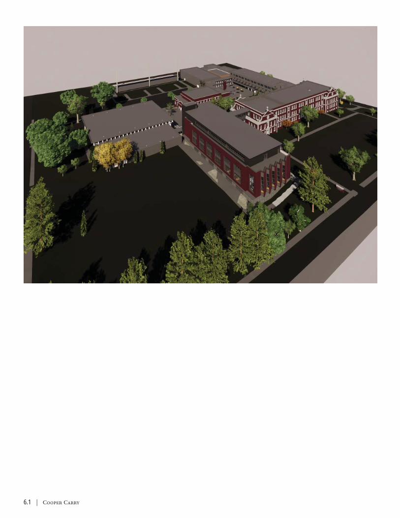
6.1 | Cooper Carry
Grady High School | 6.2
1. ARCHITECTURAL SITE PLAN2. ARCHITECTURAL FLOOR PLANS - ADDITION GROUND FLOOR3. ARCHITECTURAL FLOOR PLANS - ADDITION SECOND FLOOR4. ARCHITECTURAL FLOOR PLANS - ADDITION THIRD FLOOR5. ARCHITECTURAL FLOOR PLANS - ADDITION FOURTH FLOOR6. ARCHITECTURAL ELEVATIONS - 17. ARCHITECTURAL ELEVATIONS - 28. EXISTING BUILDING - CAFETERIA RENOVATION9. EXISTING BUILDING - ADMIN RENOVATION10. EXISTING BUILDING - FAMILY LIVING CENTER
SECTION VIGRAPHICS
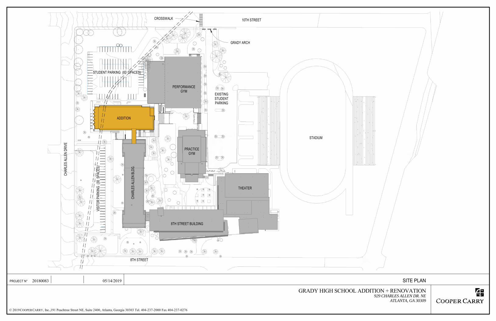
10TH STREET
CHAR
LES
ALLE
N DR
IVE
8TH STREET
ADDITION
PERFORMANCE GYM
CHAR
LES
ALLE
N BL
DG.
VISI
TOR
PARK
ING
(30
SPAC
ES)
8TH STREET BUILDING
THEATER
PRACTICE GYM
STADIUM
EXISTING STUDENT PARKING
CROSSWALK
GRADY ARCH
STUDENT PARKING (87 SPACES)
191 Peachtree Street NE, Suite 2400, Atlanta, Georgia 30303 Tel. 404-237-2000 Fax 404-237-0276
PROJECT N°
© 2019 , Inc.,C COOPER ARRY
20180083 05/14/2019 SITE PLAN
GRADY HIGH SCHOOL ADDITION + RENOVATION929 CHARLES ALLEN DR. NE
ATLANTA, GA 30309

UP
UP
CHARLES ALLEN BUILDING (CRAWL SPACE)
TRUN
K SE
WER
1,166 SFE+T LAB
3,115 SFENG. + TECH SHOP
976 SFFLEX CR875 SF
STOR. + MECH.438 SFSTOR.
232 SFOFFICE
527 SFVEST.
ELEC.
MDF
EMR
494 SFMETALS
1,173 SFE+T CR 247 SF
M247 SF
W
LEGEND
Classroom
CTAE
OUTDOOR WORK AREA
GENE
RATO
R
191 Peachtree Street NE, Suite 2400, Atlanta, Georgia 30303 Tel. 404-237-2000 Fax 404-237-0276
PROJECT N°
© 2019 , Inc.,C COOPER ARRY
20180083 10/24/18 ADDITION - GROUND FLOOR PLAN
GRADY HIGH SCHOOL ADDITION + RENOVATION929 CHARLES ALLEN DR. NE
ATLANTA, GA 30309
20105 40

PERFORMANCE GYM
ROOF
ENTRY PLAZA
LEGEND
Admin + Office
Media Center
5,398 SFMEDIA CENTER
1,131 SFPARENTS & CCC
366 SFSCHOOL STORE
ELEC.
MDF
M W
110 SFOFFICE
161 SFOFFICE
114 SFOFFICE
113 SFOFFICE
1,029 SFCOUNSELING
111 SFOFFICE
195 SFSTORAGE
114 SFOFFICE
255 SFMEETING
312 SFCONF.
229 SFWORK
403 SFMAKER
107 SFSTOR.
115 SFOFFICE
191 Peachtree Street NE, Suite 2400, Atlanta, Georgia 30303 Tel. 404-237-2000 Fax 404-237-0276
PROJECT N°
© 2019 , Inc.,C COOPER ARRY
20180083 10/24/18 ADDITION 2ND FLOOR PLAN
GRADY HIGH SCHOOL ADDITION + RENOVATION929 CHARLES ALLEN DR. NE
ATLANTA, GA 30309
30158 60

PERFORMANCE GYM ROOF
LEGEND
Admin + Office
Classroom - SOCS
751 SFCR7
796 SFCR8
852 SFCR10
808 SFCR3
785 SFCR5
793 SFCR6
789 SFCR2
808 SFCR4
790 SFCR1
796 SFCR9 ELEC.
MDF
OPEN TO MEDIA CENTER BELOW
332 SFSTOR.
M W
163 SFADMIN
482 SFWORK
191 Peachtree Street NE, Suite 2400, Atlanta, Georgia 30303 Tel. 404-237-2000 Fax 404-237-0276
PROJECT N°
© 2019 , Inc.,C COOPER ARRY
20180083 10/24/18 ADDITION THIRD FLOOR PLAN
GRADY HIGH SCHOOL ADDITION + RENOVATION929 CHARLES ALLEN DR. NE
ATLANTA, GA 30309
30158 60
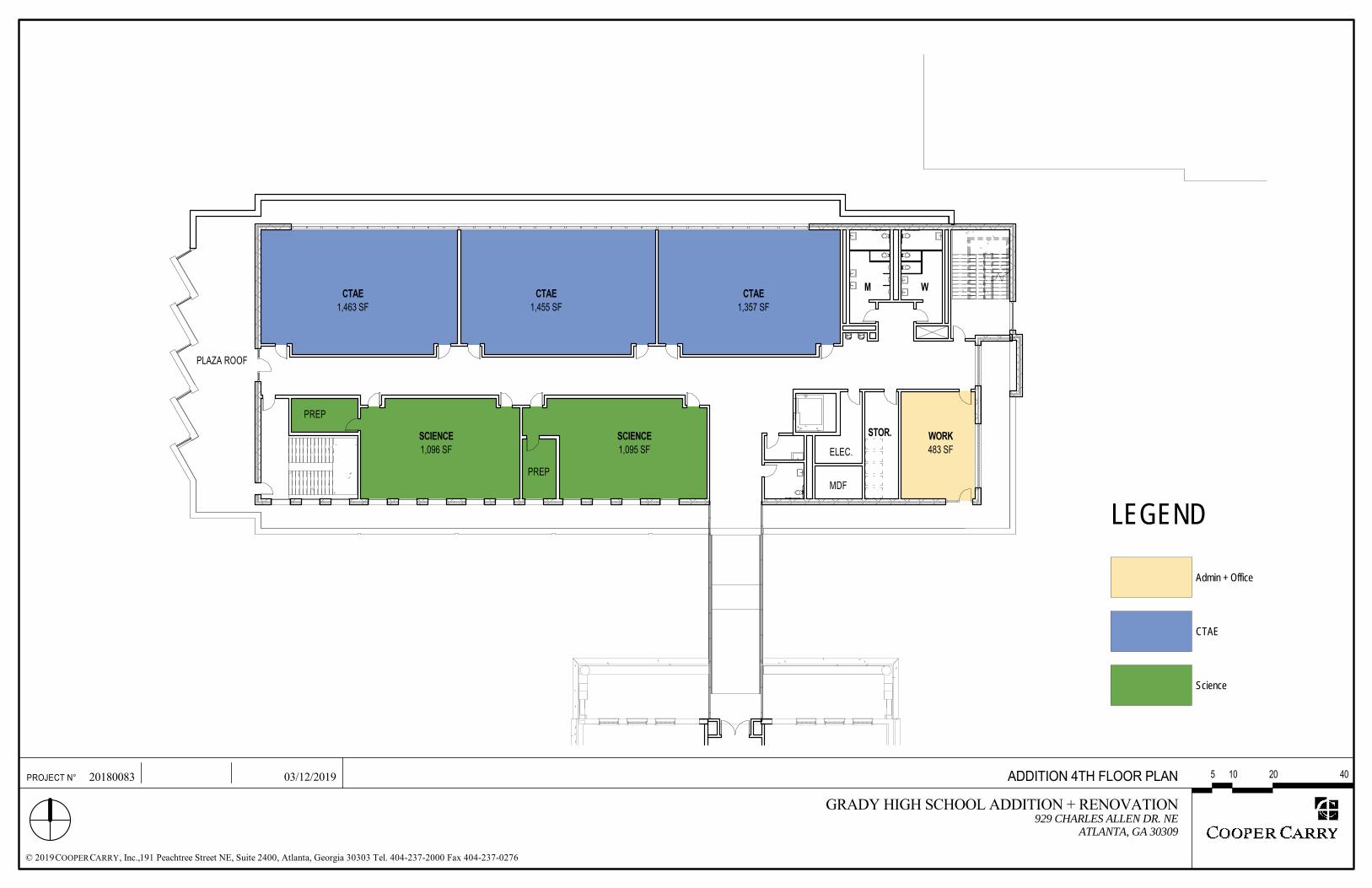
LEGEND
Admin + Office
CTAE
Science
1,463 SFCTAE
1,455 SFCTAE
1,095 SFSCIENCE
1,096 SFSCIENCE
1,357 SFCTAE
483 SFWORK
ELEC.
MDF
STOR.
M W
PLAZA ROOF
PREP
PREP
191 Peachtree Street NE, Suite 2400, Atlanta, Georgia 30303 Tel. 404-237-2000 Fax 404-237-0276
PROJECT N°
© 2019 , Inc.,C COOPER ARRY
20180083 03/12/2019 ADDITION 4TH FLOOR PLAN
GRADY HIGH SCHOOL ADDITION + RENOVATION929 CHARLES ALLEN DR. NE
ATLANTA, GA 30309
20105 40
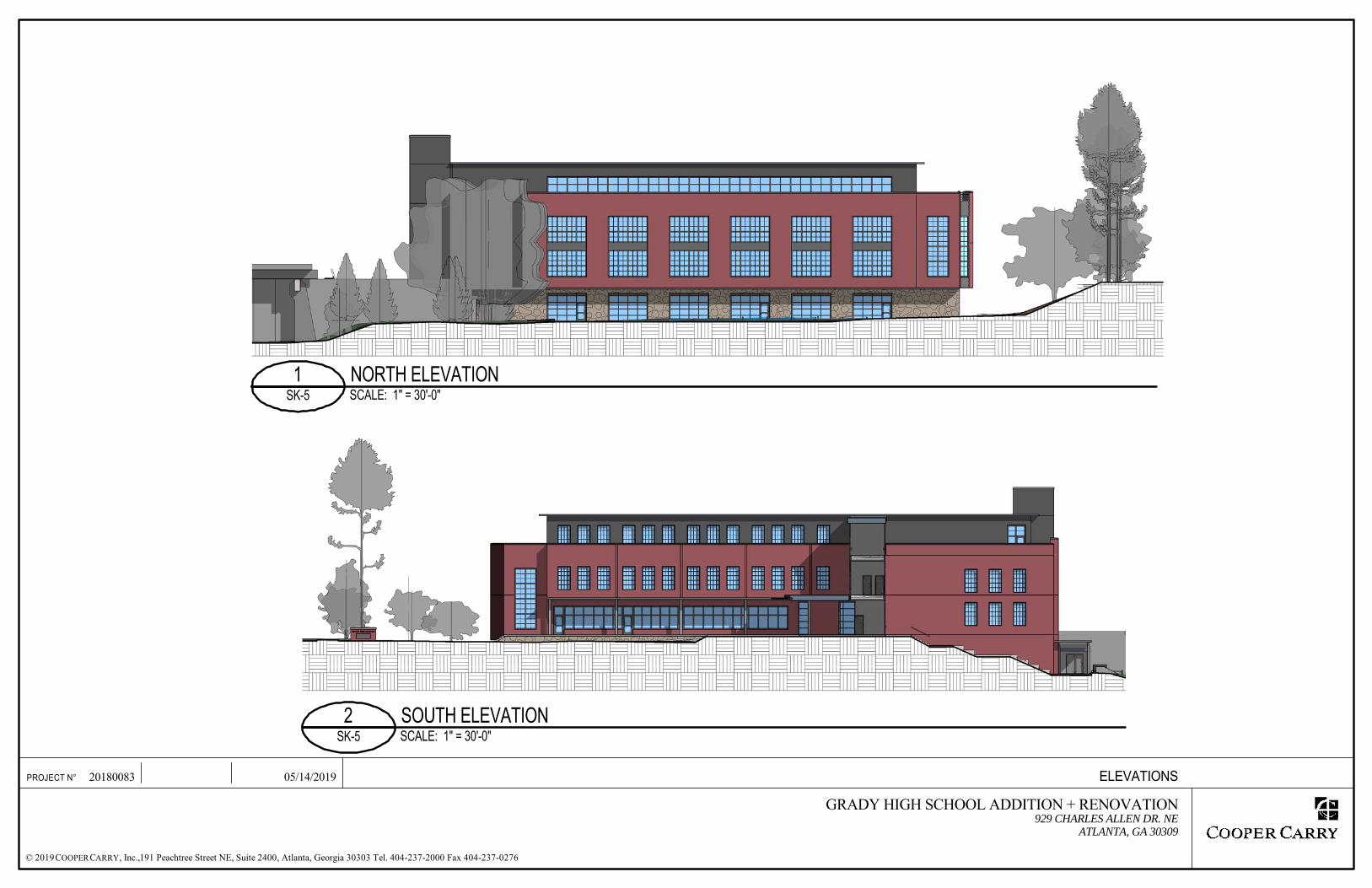
191 Peachtree Street NE, Suite 2400, Atlanta, Georgia 30303 Tel. 404-237-2000 Fax 404-237-0276
PROJECT N°
© 2019 , Inc.,C COOPER ARRY
20180083 05/14/2019 ELEVATIONS
GRADY HIGH SCHOOL ADDITION + RENOVATION929 CHARLES ALLEN DR. NE
ATLANTA, GA 30309
SCALE: 1" = 30'-0"SK-51 NORTH ELEVATION
SCALE: 1" = 30'-0"SK-52 SOUTH ELEVATION

191 Peachtree Street NE, Suite 2400, Atlanta, Georgia 30303 Tel. 404-237-2000 Fax 404-237-0276
PROJECT N°
© 2019 , Inc.,C COOPER ARRY
20180083 05/14/2019 ELEVATIONS
GRADY HIGH SCHOOL ADDITION + RENOVATION929 CHARLES ALLEN DR. NE
ATLANTA, GA 30309
SCALE: 1" = 30'-0"SK-61 WEST ELEVATION
SCALE: 1" = 30'-0"SK-62 EAST ELEVATION

INSTALL NEW EXIT DOOR FROM MULTIPURPOSE ROOM CENTER
EXPAND CAFETERIA INTO INTERACTIVE LAB
1,396 SFCTAE
3,234 SFMULTIPURPOSE ROOM
8,831 SFCAFETERIA
STRUCTURAL BRACING TO REMAIN
SEATING LAYOUT SHOWS 142 SEATS CAFETERIA SEATING
LAYOUT SHOWS 684 SEATS
OPTION TO INSTALL FOLDING PARTITION
DASHED ITEMS TO BE DEMOLISHED
191 Peachtree Street NE, Suite 2400, Atlanta, Georgia 30303 Tel. 404-237-2000 Fax 404-237-0276
PROJECT N°
© 2019 , Inc.,C COOPER ARRY
20180083 05/14/2019 EX. GROUND FL.- 8TH ST. BLDG.
GRADY HIGH SCHOOL ADDITION + RENOVATION929 CHARLES ALLEN DR. NE
ATLANTA, GA 30309
30158 60
REMOVALS PLAN
PROPOSED PLAN
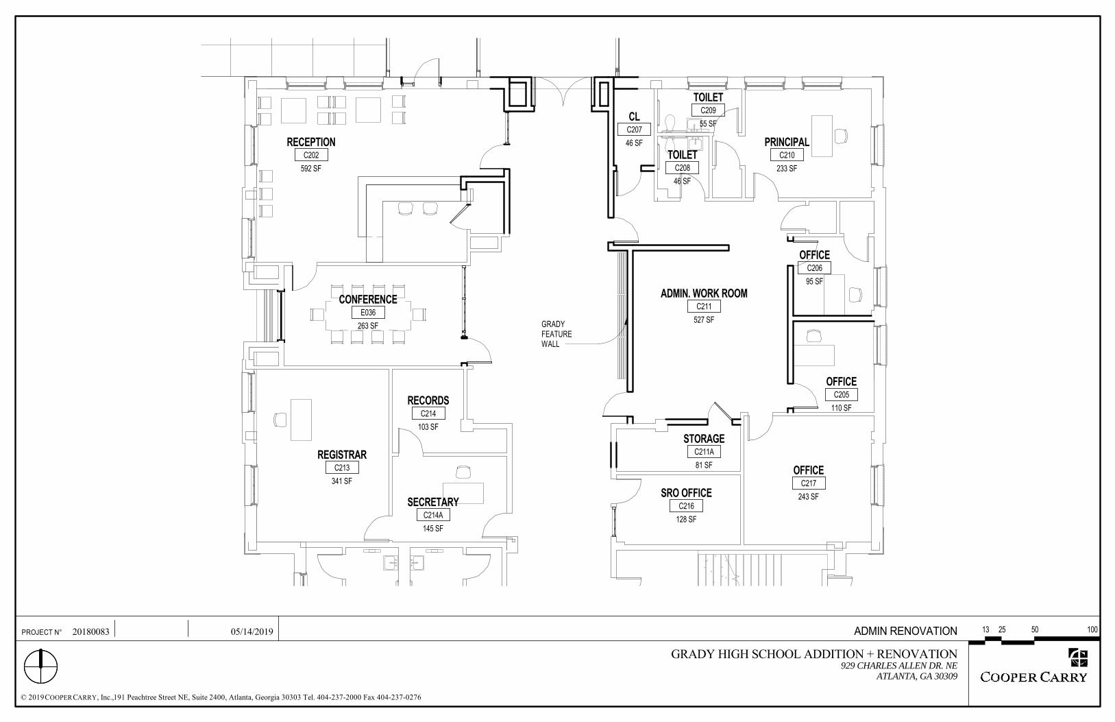
592 SF
RECEPTIONC202
263 SF
CONFERENCEE036
341 SF
REGISTRARC213
103 SF
RECORDSC214
145 SF
SECRETARYC214A
81 SF
STORAGEC211A
243 SF
OFFICEC217
527 SF
ADMIN. WORK ROOMC211
110 SF
OFFICEC205
95 SF
OFFICEC206
233 SF
PRINCIPALC210
46 SF
CLC207
128 SF
SRO OFFICEC216
GRADY FEATURE WALL
55 SF
TOILETC209
46 SF
TOILETC208
191 Peachtree Street NE, Suite 2400, Atlanta, Georgia 30303 Tel. 404-237-2000 Fax 404-237-0276
PROJECT N°
© 2019 , Inc.,C COOPER ARRY
20180083 05/14/2019 ADMIN RENOVATION
GRADY HIGH SCHOOL ADDITION + RENOVATION929 CHARLES ALLEN DR. NE
ATLANTA, GA 30309
502513 100

FD
136 SF
PEC TOILETE222
1,000 SF
FAM. LIV. CENTERE220
908 SF
PEC CRE224
68 SF
STOR.E221
REF. DW W D
191 Peachtree Street NE, Suite 2400, Atlanta, Georgia 30303 Tel. 404-237-2000 Fax 404-237-0276
PROJECT N°
© 2019 , Inc.,C COOPER ARRY
20180083 05/14/2019 RENOVATION - 8TH ST. BLDG. - FAMILY LIVING CENTER
GRADY HIGH SCHOOL ADDITION + RENOVATION929 CHARLES ALLEN DR. NE
ATLANTA, GA 30309

191 Peachtree Street NE, Suite 2400, Atlanta, Georgia 30303 Tel. 404-237-2000 Fax 404-237-0276
PROJECT N°
© 2019 , Inc.,C COOPER ARRY
20180083 05/24/2019 PRELIMINARY RENDERING - SOUTH
GRADY HIGH SCHOOL ADDITION + RENOVATION929 CHARLES ALLEN DR. NE
ATLANTA, GA 30309
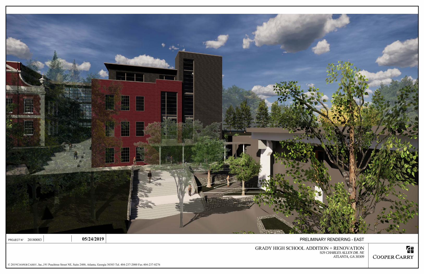
191 Peachtree Street NE, Suite 2400, Atlanta, Georgia 30303 Tel. 404-237-2000 Fax 404-237-0276
PROJECT N°
© 2019 , Inc.,C COOPER ARRY
20180083 05/24/2019 PRELIMINARY RENDERING - EAST
GRADY HIGH SCHOOL ADDITION + RENOVATION929 CHARLES ALLEN DR. NE
ATLANTA, GA 30309

191 Peachtree Street NE, Suite 2400, Atlanta, Georgia 30303 Tel. 404-237-2000 Fax 404-237-0276
PROJECT N°
© 2019 , Inc.,C COOPER ARRY
20180083 05/24/2019 PRELIMINARY ELEVATION - NORTH
GRADY HIGH SCHOOL ADDITION + RENOVATION929 CHARLES ALLEN DR. NE
ATLANTA, GA 30309

191 Peachtree Street NE, Suite 2400, Atlanta, Georgia 30303 Tel. 404-237-2000 Fax 404-237-0276
PROJECT N°
© 2019 , Inc.,C COOPER ARRY
20180083 05/24/2019 PRELIMINARY RENDERING - WEST
GRADY HIGH SCHOOL ADDITION + RENOVATION929 CHARLES ALLEN DR. NE
ATLANTA, GA 30309

covertemplatesmall.indd 2covertemplatesmall.indd 2 5/3/2019 5:26:26 PM5/3/2019 5:26:26 PM