Embed Size (px)
Citation preview
Pilot’s Operating Handbook
GPSSHDG
5th Ed. Feb 15, 08 i
S–TEC
List of Effective Pages * Asterisk indicates pages changed, added, or deleted by current revision.
Record of Revisions Retain this record in front of handbook. Upon receipt of a revision, insert changes and complete table below.
Revision Number Revision Date Insertion Date/Initials 1st Ed. Mar 14, 00 2nd Ed. Dec 13, 00 3rd Ed. Jan 14, 02 4th Ed. Sep 05, 03 5th Ed. Feb 15, 08

ii 5th Ed. Feb 15, 08
S–TEC
Page Intentionally Blank
5th Ed. Feb 15, 08 iii
S–TEC
Table of ContentsSec. Pg.
1 Overview...........................................................................................................1–1
1.1 Document Organization....................................................................1–3
1.2 Purpose..............................................................................................1–3
1.3 General Control Theory....................................................................1–3
1.4 Block Diagram....................................................................................1–4
2 Pre-Flight Procedures...................................................................................2–1
2.1 Pre-Flight Test....................................................................................2–3
3 In-Flight Procedures......................................................................................3–1
3.1 Normal Operating Procedures........................................................3–3
3.1.1 Heading (HDG) Mode........................................................3–3
3.1.2 Global Positioning System Steering (GPSS) Mode.......3–3
3.2 Approach Procedures.......................................................................3–4
3.2.1 Standard Approach.............................................................3–4
3.2.2 GPS Overlay of VOR / DME-A Approach...........................3–4
3.2.3 GPS-T Approach.................................................................3–4
3.2.4 GPS Approach with Holding Pattern................................3–4
3.2.5 GPS Overlay of VOR Approach with Procedure Turn.....3–4
3.3 Emergency Procedures....................................................................3–9
4 Operating Parameters..................................................................................4–1
4.1 Ranges.................................................................................................4–3
5 Glossary...........................................................................................................5–1
iv 5th Ed. Feb 15, 08
S–TEC
List of FiguresFig. Pg.
1–1 HDG / GPSS Selector Switch.......................................................................1–5
1–2 ST-901 GPSS Converter Block Diagram...................................................1–5
2–1 HDG / GPSS Selector Switch (Pre-Flight)..................................................2–4
3–1 GPS Overlay of VOR / DME-A Approach......................................................3–5
3–2 GPS-T Approach.............................................................................................3–6
3–3 GPS Approach with Holding Pattern...........................................................3–7
3–4 GPS Overlay of VOR Approach with Procedure Turn................................3–8
List of TablesTable Pg.
2–1 Pre-Flight Test...............................................................................................2–3

5th Ed. Feb 15, 08 1-1
S–TEC
SECTION 1OVERVIEW

1-2 5th Ed. Feb 15, 08
S–TEC
Page Intentionally Blank
5th Ed. Feb 15, 08 1-3
S–TEC
1.1 Document Organization
Section 1 Overview
Section 2 Pre-Flight Procedures
Section 3 In-Flight Procedures
Section 4 Operating Parameters
Section 5 Glossary
1.2 Purpose
This Pilot's Operating Handbook (POH) provides Pre-Flight and In-Flight operatingprocedures for the S-TEC ST-901 Global Positioning System Steering (GPSS)Converter.
Note:
This POH must be carried in the A/C and made available to the pilot atall times. It can only be used in conjunction with the Federal AviationAdministration (FAA) approved Aircraft Flight Manual (AFM) or Aircraft FlightManual Supplement (AFMS). Refer to the applicable AFM or AFMS forA/C specific information, such as unique ground tests, limitations, andemergency procedures.
Note:
The GPSS Converter is a tool provided to aircraft owners, that serves toassist them with cockpit workload management. The ability of theGPSS Converter to provide optimum assistance and performance isdirectly proportional to the pilot's knowledge of its operating procedures.Therefore, it is highly recommended that the pilot develop a thoroughunderstanding of the GPSS Converter and its operating procedures in VisualMeteorological Conditions (VMC), prior to using it under Instrument FlightRules (IFR).
1.3 General Control Theory
The GPSS Converter can be used with the following S-TEC autopilots:
System Twenty / Thirty
System Forty / Fifty
System Fifty Five
System Sixty Two
System Sixty Five
1-4 5th Ed. Feb 15, 08
S–TEC
It has the following modes of operation:
HDG Mode - Used to turn onto a Selected Heading and Hold it
GPSS Mode - Used to Laterally Steer along a Course defined by Waypoints,that have been programmed into the GPS Navigator
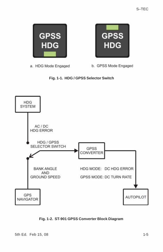
Pressing the HDG / GPSS Selector Switch will alternately engage the HDGmode and GPSS mode. This switch is shown in Fig. 1-1. As indicated, when theHDG mode is engaged, the HDG lamp is illuminated and the GPSS lamp isextinguished, but when the GPSS mode is engaged, the GPSS lamp is illuminatedand the HDG lamp is extinguished.
The GPSS Converter is internally configured to be compatible with the particularAC or DC Heading System installed in the aircraft, be it a Directional Gyro (DG)or Horizontal Situation Indicator (HSI). The output of the Heading System will beeither an AC or DC Heading Error Signal. When the GPSS Converter's HDGmode is engaged, the GPSS Converter processes the AC or DC Heading ErrorSignal at its input, to produce a proportional DC Heading Error Signal at itsoutput. This signal is sent to the input of the autopilot's heading error channel.When the autopilot's HDG mode is also engaged, the autopilot will turn theaircraft onto the selected heading and hold it.
The GPS Navigator is programmed with a sequence of waypoints, as a meansto define a course. This course is realized at the output of the GPS Navigator inthe form of two digital signals, the Bank Angle Signal and Ground Speed Signal.When the GPSS Converter's GPSS mode is engaged, the GPSS Converterprocesses the Bank Angle Signal and Ground Speed Signal at its input, toproduce a DC Turn Rate Signal at its output. This signal is sent to the input ofthe autopilot's heading error channel. When the autopilot's HDG mode is alsoengaged, the autopilot will laterally steer the aircraft along the course definedby the waypoints.
1.4 Block Diagram
The GPSS Converter Block Diagram is shown in Fig. 1-2.
5th Ed. Feb 15, 08 1-5
S–TEC
Fig. 1-2. ST-901 GPSS Converter Block Diagram
Fig. 1-1. HDG / GPSS Selector Switch

1-6 5th Ed. Feb 15, 08
S–TEC
Page Intentionally Blank
5th Ed. Feb 15, 08 2-1
S–TEC
SECTION 2PRE-FLIGHT PROCEDURES

2-2 5th Ed. Feb 15, 08
S–TEC
Page Intentionally Blank
5th Ed. Feb 15, 08 2-3
S–TEC
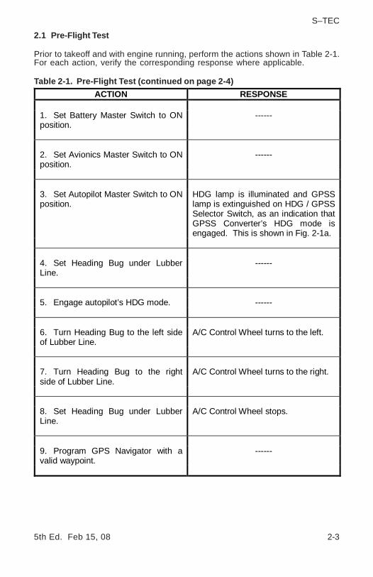
ACTION RESPONSE
1. Set Battery Master Switch to ON position.
------
2. Set Avionics Master Switch to ON position.
------
3. Set Autopilot Master Switch to ON position.
HDG lamp is illuminated and GPSS lamp is extinguished on HDG / GPSS Selector Switch, as an indication that GPSS Converter’s HDG mode is engaged. This is shown in Fig. 2-1a.
4. Set Heading Bug under Lubber Line.
------
5. Engage autopilot’s HDG mode. ------
6. Turn Heading Bug to the left side of Lubber Line.
A/C Control Wheel turns to the left.
7. Turn Heading Bug to the right side of Lubber Line.
A/C Control Wheel turns to the right.
8. Set Heading Bug under Lubber Line.
A/C Control Wheel stops.
9. Program GPS Navigator with a valid waypoint.
------
2.1 Pre-Flight Test
Prior to takeoff and with engine running, perform the actions shown in Table 2-1.For each action, verify the corresponding response where applicable.
Table 2-1. Pre-Flight Test (continued on page 2-4)

2-4 5th Ed. Feb 15, 08
S–TEC
ACTION RESPONSE
10. Press HDG / GPSS Selector Switch.
GPSS lamp is illuminated and HDG lamp is extinguished on HDG / GPSS Selector Switch, as an indication that GPSS Converter’s GPSS mode is engaged. This is shown in Fig. 2-1b.
11. Turn Heading Bug to the left side and right side of Lubber Line.
A/C Control Wheel does not respond.
Note: The GPSS mode cannot be tested since there is no groundspeed.
12. Disconnect autopilot. ------
Table 2-1. Pre-Flight Test (continued from page 2-3)
Fig. 2-1. HDG / GPSS Selector Switch
5th Ed. Feb 15, 08 3-1
S–TEC
SECTION 3IN-FLIGHT PROCEDURES

3-2 5th Ed. Feb 15, 08
S–TEC
Page Intentionally Blank
5th Ed. Feb 15, 08 3-3
S–TEC
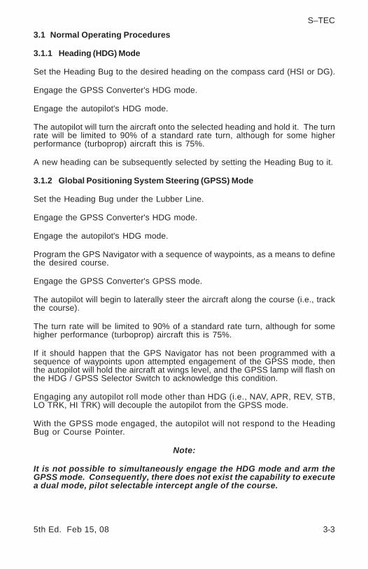
3.1 Normal Operating Procedures
3.1.1 Heading (HDG) Mode
Set the Heading Bug to the desired heading on the compass card (HSI or DG).
Engage the GPSS Converter's HDG mode.
Engage the autopilot's HDG mode.
The autopilot will turn the aircraft onto the selected heading and hold it. The turnrate will be limited to 90% of a standard rate turn, although for some higherperformance (turboprop) aircraft this is 75%.
A new heading can be subsequently selected by setting the Heading Bug to it.
3.1.2 Global Positioning System Steering (GPSS) Mode
Set the Heading Bug under the Lubber Line.
Engage the GPSS Converter's HDG mode.
Engage the autopilot's HDG mode.
Program the GPS Navigator with a sequence of waypoints, as a means to definethe desired course.
Engage the GPSS Converter's GPSS mode.
The autopilot will begin to laterally steer the aircraft along the course (i.e., trackthe course).
The turn rate will be limited to 90% of a standard rate turn, although for somehigher performance (turboprop) aircraft this is 75%.
If it should happen that the GPS Navigator has not been programmed with asequence of waypoints upon attempted engagement of the GPSS mode, thenthe autopilot will hold the aircraft at wings level, and the GPSS lamp will flash onthe HDG / GPSS Selector Switch to acknowledge this condition.
Engaging any autopilot roll mode other than HDG (i.e., NAV, APR, REV, STB,LO TRK, HI TRK) will decouple the autopilot from the GPSS mode.
With the GPSS mode engaged, the autopilot will not respond to the HeadingBug or Course Pointer.
Note:
It is not possible to simultaneously engage the HDG mode and arm theGPSS mode. Consequently, there does not exist the capability to executea dual mode, pilot selectable intercept angle of the course.

3-4 5th Ed. Feb 15, 08
S–TEC
3.2 Approach Procedures
3.2.1 Standard Approach
Set the Heading Bug under the Lubber Line.
Engage the GPSS Converter's HDG mode.
Engage the autopilot's HDG mode.
Program the GPS Navigator with the desired approach.
Engage the GPSS Converter's GPSS mode.
The autopilot will begin tracking to the Initial Approach Fix (IAF).
To execute any required procedure turn or holding pattern, proceed as follows:
1. Engage the GPSS Converter's HDG mode.
2. Lead the aircraft around the procedure turn or holding pattern using theHeading Bug.
3. Once established on the inbound course, engage the GPSS Converter'sGPSS mode.
4. Complete the approach.
3.2.2 GPS Overlay of VOR / DME-A Approach
Refer to Fig. 3-1.
3.2.3 GPS-T Approach
Refer to Fig. 3-2.
3.2.4 GPS Approach with Holding Pattern
Refer to Fig. 3-3.
3.2.5 GPS Overlay of VOR Approach with Procedure Turn
Refer to Fig. 3-4.
5th Ed. Feb 15, 08 3-5
S–TEC
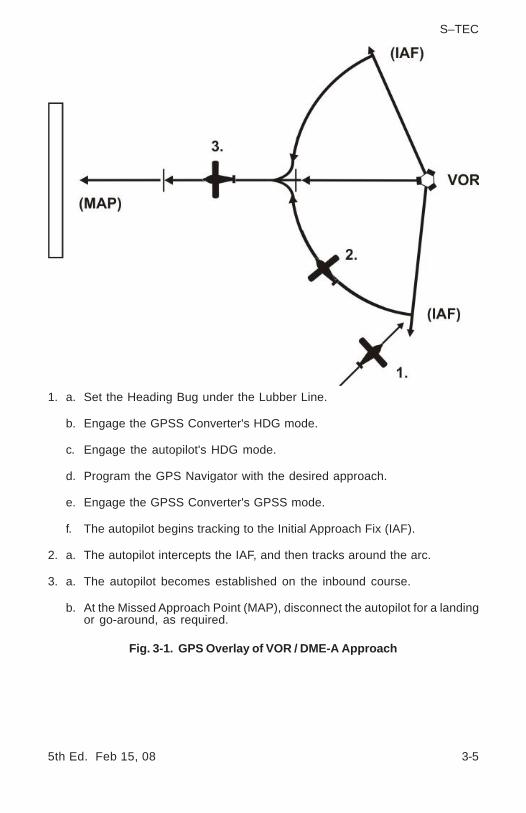
Fig. 3-1. GPS Overlay of VOR / DME-A Approach
1. a. Set the Heading Bug under the Lubber Line.
b. Engage the GPSS Converter's HDG mode.
c. Engage the autopilot's HDG mode.
d. Program the GPS Navigator with the desired approach.
e. Engage the GPSS Converter's GPSS mode.
f. The autopilot begins tracking to the Initial Approach Fix (IAF).
2. a. The autopilot intercepts the IAF, and then tracks around the arc.
3. a. The autopilot becomes established on the inbound course.
b. At the Missed Approach Point (MAP), disconnect the autopilot for a landingor go-around, as required.
3-6 5th Ed. Feb 15, 08
S–TEC
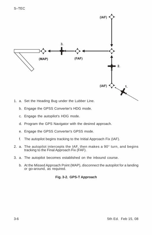
Fig. 3-2. GPS-T Approach
1. a. Set the Heading Bug under the Lubber Line.
b. Engage the GPSS Converter's HDG mode.
c. Engage the autopilot's HDG mode.
d. Program the GPS Navigator with the desired approach.
e. Engage the GPSS Converter's GPSS mode.
f. The autopilot begins tracking to the Initial Approach Fix (IAF).
2. a. The autopilot intercepts the IAF, then makes a 90° turn, and beginstracking to the Final Approach Fix (FAF).
3. a. The autopilot becomes established on the inbound course.
b. At the Missed Approach Point (MAP), disconnect the autopilot for a landingor go-around, as required.
5th Ed. Feb 15, 08 3-7
S–TEC
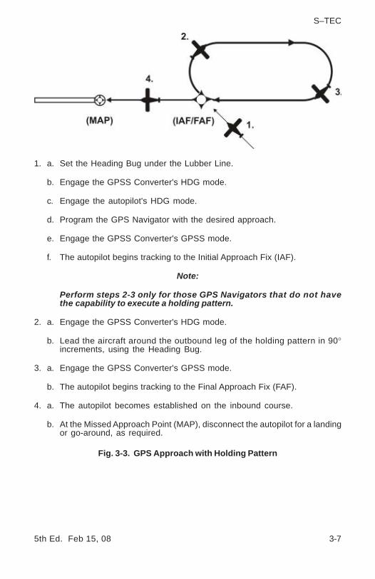
Fig. 3-3. GPS Approach with Holding Pattern
1. a. Set the Heading Bug under the Lubber Line.
b. Engage the GPSS Converter's HDG mode.
c. Engage the autopilot's HDG mode.
d. Program the GPS Navigator with the desired approach.
e. Engage the GPSS Converter's GPSS mode.
f. The autopilot begins tracking to the Initial Approach Fix (IAF).
Note:
Perform steps 2-3 only for those GPS Navigators that do not havethe capability to execute a holding pattern.
2. a. Engage the GPSS Converter's HDG mode.
b. Lead the aircraft around the outbound leg of the holding pattern in 90°increments, using the Heading Bug.
3. a. Engage the GPSS Converter's GPSS mode.
b. The autopilot begins tracking to the Final Approach Fix (FAF).
4. a. The autopilot becomes established on the inbound course.
b. At the Missed Approach Point (MAP), disconnect the autopilot for a landingor go-around, as required.
3-8 5th Ed. Feb 15, 08
S–TEC
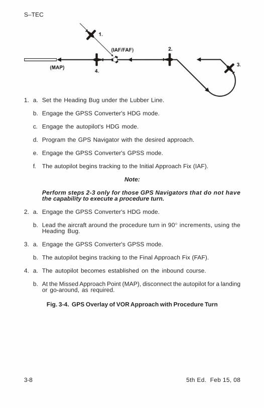
Fig. 3-4. GPS Overlay of VOR Approach with Procedure Turn
1. a. Set the Heading Bug under the Lubber Line.
b. Engage the GPSS Converter's HDG mode.
c. Engage the autopilot's HDG mode.
d. Program the GPS Navigator with the desired approach.
e. Engage the GPSS Converter's GPSS mode.
f. The autopilot begins tracking to the Initial Approach Fix (IAF).
Note:
Perform steps 2-3 only for those GPS Navigators that do not havethe capability to execute a procedure turn.
2. a. Engage the GPSS Converter's HDG mode.
b. Lead the aircraft around the procedure turn in 90° increments, using theHeading Bug.
3. a. Engage the GPSS Converter's GPSS mode.
b. The autopilot begins tracking to the Final Approach Fix (FAF).
4. a. The autopilot becomes established on the inbound course.
b. At the Missed Approach Point (MAP), disconnect the autopilot for a landingor go-around, as required.

5th Ed. Feb 15, 08 3-9
S–TEC
3.3 Emergency Procedures
In the event of a GPSS Converter malfunction, proceed as follows:
1. Disconnect the autopilot.
2. Regain control of the aircraft.
3. Do Not attempt to use the GPSS Converter's HDG mode or GPSS mode.
4. Do Not attempt to use the autopilot's HDG mode.
Note:
It may be possible to use other autopilot roll modes (i.e., NAV, APR, REV, STB,LO TRK, HI TRK).

3-10 5th Ed. Feb 15, 08
S–TEC
Page Intentionally Blank

5th Ed. Feb 15, 08 4-1
S–TEC
SECTION 4OPERATING PARAMETERS

4-2 5th Ed. Feb 15, 08
S–TEC
Page Intentionally Blank

5th Ed. Feb 15, 08 4-3
S–TEC
4.1 Roll Axis Limits
Turn Rate
Piston A/C:
90% Standard Rate Turn
Turboprop A/C:
75% Standard Rate Turn

4-4 5th Ed. Feb 15, 08
S–TEC
Page Intentionally Blank

5th Ed. Feb 15, 08 5-1
S–TEC
SECTION 5GLOSSARY

5-2 5th Ed. Feb 15, 08
S–TEC
Page Intentionally Blank
5th Ed. Feb 15, 08 5-3
S–TEC
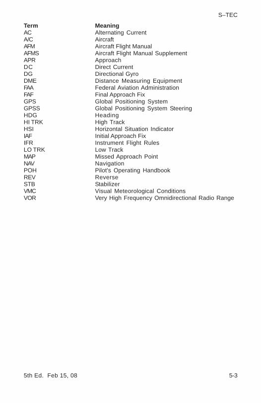
Term MeaningAC Alternating CurrentA/C AircraftAFM Aircraft Flight ManualAFMS Aircraft Flight Manual SupplementAPR ApproachDC Direct CurrentDG Directional GyroDME Distance Measuring EquipmentFAA Federal Aviation AdministrationFAF Final Approach FixGPS Global Positioning SystemGPSS Global Positioning System SteeringHDG HeadingHI TRK High TrackHSI Horizontal Situation IndicatorIAF Initial Approach FixIFR Instrument Flight RulesLO TRK Low TrackMAP Missed Approach PointNAV NavigationPOH Pilot's Operating HandbookREV ReverseSTB StabilizerVMC Visual Meteorological ConditionsVOR Very High Frequency Omnidirectional Radio Range

5-4 5th Ed. Feb 15, 08
S–TEC
Page Intentionally Blank

One S–TEC WayMunicipal Airport
Mineral Wells, TX 76067–9236 Tel: 800–872–7832Fax: 940–325–3904
www.genesys-aerosystems.comS–TEC PN 8799
Information contained in this document is subject to changewithout notice. © 2008 S-TEC. All rights reserved. Printed inthe United States of America. S-TEC and the S-TEC logoare registered trademarks of S-TEC.
Notice:Contact S-TEC Customer Support at 800-872-7832 for aService Repair Order (SRO) number prior to the return of anycomponent for any reason.