Embed Size (px)
Citation preview
GPS/GPRS/GSM Module V3.0 (SKU:TEL0051)
From Robot Wiki
Contents
1 Introduction2 Specification
3 Pin Out4 Tutorial
4.1 How to drive the GSM
Mode via USB port
4.1.1 GSM mode &
GPS mode Selection
4.1.2 Network
indication
4.1.3 How to Send amessage
4.1.4 Ways to send
Ctrl +Z in Coolterm
4.1.5 How to Make a
phone call4.2 How to drive the GPS
Mode via USB port
4.3 How to drive the GSM Mode via Arduino board
4.3.1 How to Send a message
4.3.2 How to Control your Arduino via SMS
4.3.3 How to Make a phone call
4.4 How to drive the GPS Mode via Arduino board
5 GPS Sample Code6 Trouble shooting
7 Version history
Introduction
This is a GPS/GPRS/GSM shield from DFRobot. This shield with a Quad-band GSM/GPRS engine works onfrequencies EGSM 900MHz/DCS 1800MHz and GSM850 MHz/PCS 1900MHz. It also supports GPStechnology for satellite navigation. It's possible for your robot and control system to send messages and use theGSM network.
It is controlled via AT commands(GSM07.07 ,07.05 and SIMCOM enhanced AT Commands). And the design ofthis shield allows you to drive the GSM & GPS function directly with the computer and the Arduino Board. Itincludes a high-gain SMD antenna for GPS & GSM.
This GPS/GPRS/GSM shield uses an embedded SIM908 chip from SIMCom.Featuring an industry-standardinterface and GPS function, the combination of both technologies allows goods, vehicles and people to be trackedseamlessly at any location and anytime with signal coverage.
Specification
Power supply: 6-12v
Low power consumption (100mA@7v - GSM mode)
Quad-Band 850/900/1800/1900MHz
GPRS multi-slot class 10
Support GPS technology for satellite navigation
Embeded high-gain SMD antennas for GPS & GSM
Directly support 4*4 button pad
USB/Arduino control switch
Board Surface:Immersion GoldSize: 81x70mm
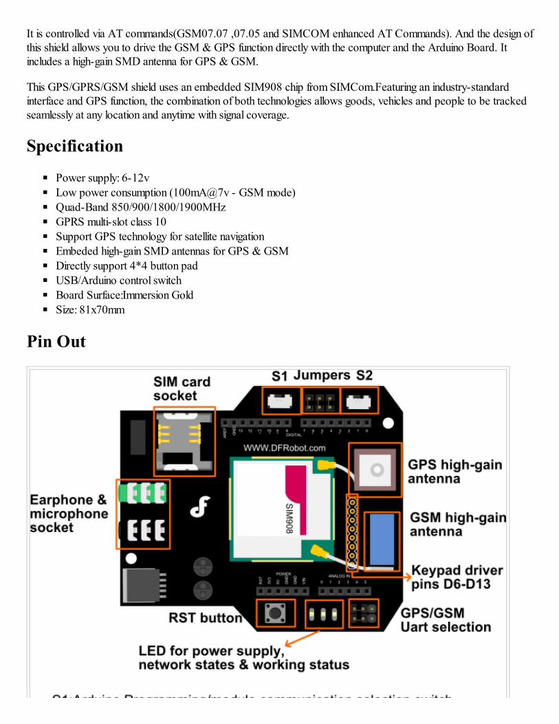
Pin Out
NOTE: Two jumper caps of GPS/GSM UART SELECTION have been changed to a switch."Take off the jumper caps" do the same function of
"slid the switch in the middle".
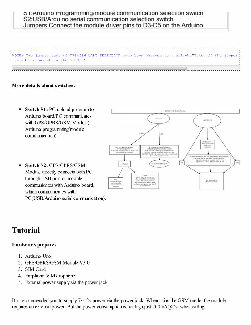
More details about switches:
Switch S1: PC upload program toArduino board/PC communicateswith GPS/GPRS/GSM Module(
Arduino programming/modulecommunication).
Switch S2: GPS/GPRS/GSMModule directly connects with PC
through USB port or modulecommunicates with Arduino board,
which communicates withPC(USB/Arduino serial communication).
Tutorial
Hardwares prepare:
1. Arduino Uno2. GPS/GPRS/GSM Module V3.0
3. SIM Card
4. Earphone & Microphone
5. External power supply via the power jack
It is recommended you to supply 7~12v power via the power jack. When using the GSM mode, the modulerequires an external power. But the power consumption is not high,just 200mA@7v, when calling.
Module driver pin jumpers: Applying the Module Pin Jumpers(J10-J12) will allocate Pin 3,4,5 for driving themodule. Removing the jumpers will release the above Pins, and you could connect the driver pins to the other digitalpins on your board to avoid the pin conflict.Read more (http://www.dfrobot.com/forum/index.php?topic=17186.msg21374#msg21374)
How to drive the GSM Mode via USB port
1. If your module works, the indicator Start LED will light up, this means that the module is running correctly.
The LED marked "NET" is used to drive a network status indication LED.
2. Send the AT commands to the module by using Coolterm (http://freeware.the-meiers.org/CoolTermWin.zip)
(or use the Arduino serial monitor).
Note: If you want to program the Arduino, please disconnect the coolterm to release the communication port.
GSM mode & GPS mode Selection
Except using UART selection jumper caps, you could switch GSM and GPS function with the IO pins also. Pleaseremove the jumper caps connected for hardware UART selection first!
Enable GPS mode & disable GSM mode:
digitalWrite(4,LOW);//Enable GPS mode
digitalWrite(3,HIGH);//Disable GSM mode
Enable GSM mode & disable GPS mode:
digitalWrite(3,LOW);//Enable GSM modedigitalWrite(4,HIGH);//Disable GPS mode
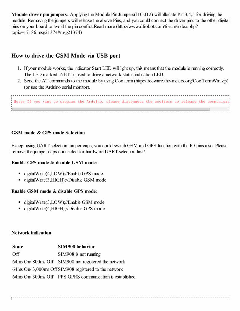
Network indication
State SIM908 behavior
Off SIM908 is not running
64ms On/ 800ms Off SIM908 not registered the network
64ms On/ 3,000ms Off SIM908 registered to the network
64ms On/ 300ms Off PPS GPRS communication is established
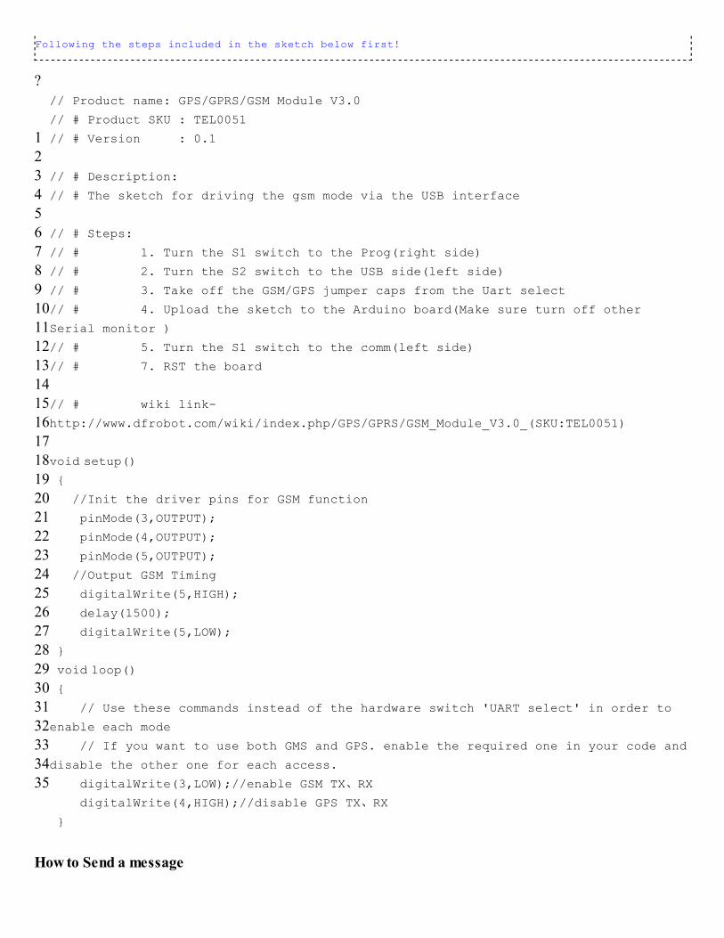
Following the steps included in the sketch below first!
?
1
2
34
5
6
78
9
10
1112
13
1415
16
17
1819
20
21
2223
24
2526
27
28
2930
31
32
3334
35
// Product name: GPS/GPRS/GSM Module V3.0
// # Product SKU : TEL0051
// # Version : 0.1
// # Description:
// # The sketch for driving the gsm mode via the USB interface
// # Steps:
// # 1. Turn the S1 switch to the Prog(right side)
// # 2. Turn the S2 switch to the USB side(left side)
// # 3. Take off the GSM/GPS jumper caps from the Uart select
// # 4. Upload the sketch to the Arduino board(Make sure turn off other
Serial monitor )
// # 5. Turn the S1 switch to the comm(left side)
// # 7. RST the board
// # wiki link-
http://www.dfrobot.com/wiki/index.php/GPS/GPRS/GSM_Module_V3.0_(SKU:TEL0051)
void setup() {
//Init the driver pins for GSM function
pinMode(3,OUTPUT);
pinMode(4,OUTPUT);
pinMode(5,OUTPUT);
//Output GSM Timing
digitalWrite(5,HIGH);
delay(1500);
digitalWrite(5,LOW);
}
void loop() {
// Use these commands instead of the hardware switch 'UART select' in order to
enable each mode
// If you want to use both GMS and GPS. enable the required one in your code and
disable the other one for each access.
digitalWrite(3,LOW);//enable GSM TX、RX
digitalWrite(4,HIGH);//disable GPS TX、RX
}
How to Send a message
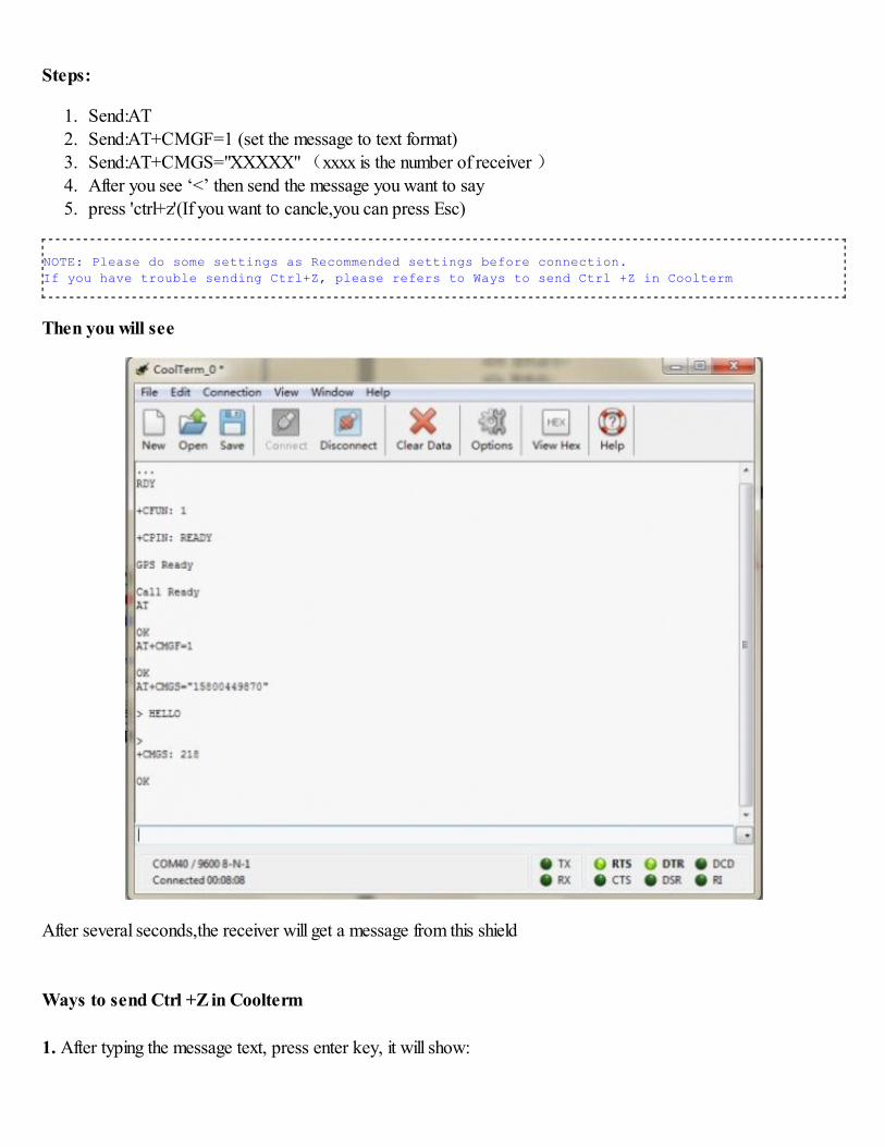
Steps:
1. Send:AT
2. Send:AT+CMGF=1 (set the message to text format)
3. Send:AT+CMGS="XXXXX" (xxxx is the number of receiver )
4. After you see ‘<’ then send the message you want to say5. press 'ctrl+z'(If you want to cancle,you can press Esc)
NOTE: Please do some settings as Recommended settings before connection.
If you have trouble sending Ctrl+Z, please refers to Ways to send Ctrl +Z in Coolterm
Then you will see
After several seconds,the receiver will get a message from this shield
Ways to send Ctrl +Z in Coolterm
1. After typing the message text, press enter key, it will show:
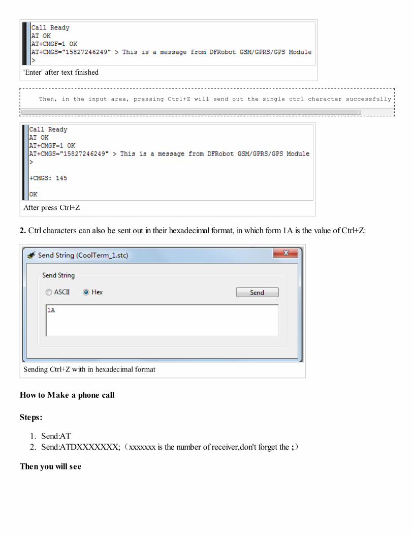
'Enter' after text finished
Then, in the input area, pressing Ctrl+Z will send out the single ctrl character successfully as below:
After press Ctrl+Z
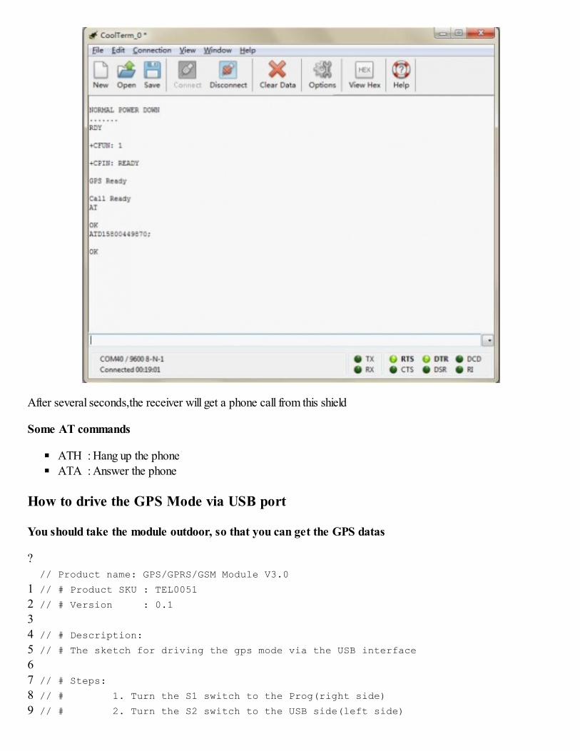
2. Ctrl characters can also be sent out in their hexadecimal format, in which form 1A is the value of Ctrl+Z:
Sending Ctrl+Z with in hexadecimal format
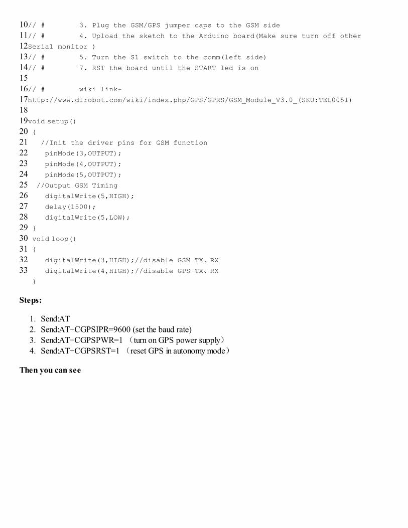
How to Make a phone call
Steps:
1. Send:AT
2. Send:ATDXXXXXXX;(xxxxxxx is the number of receiver,don't forget the ;)
Then you will see
After several seconds,the receiver will get a phone call from this shield
Some AT commands
ATH : Hang up the phone
ATA : Answer the phone
How to drive the GPS Mode via USB port
You should take the module outdoor, so that you can get the GPS datas
?
1
2
34
5
6
7
8
9
// Product name: GPS/GPRS/GSM Module V3.0
// # Product SKU : TEL0051
// # Version : 0.1
// # Description:
// # The sketch for driving the gps mode via the USB interface
// # Steps:
// # 1. Turn the S1 switch to the Prog(right side)
// # 2. Turn the S2 switch to the USB side(left side)
10
11
12
13
14
15
16
1718
19
20
21
22
23
2425
26
27
28
29
30
3132
33
// # 3. Plug the GSM/GPS jumper caps to the GSM side
// # 4. Upload the sketch to the Arduino board(Make sure turn off other
Serial monitor )
// # 5. Turn the S1 switch to the comm(left side)
// # 7. RST the board until the START led is on
// # wiki link-
http://www.dfrobot.com/wiki/index.php/GPS/GPRS/GSM_Module_V3.0_(SKU:TEL0051)
void setup()
{
//Init the driver pins for GSM function
pinMode(3,OUTPUT);
pinMode(4,OUTPUT);
pinMode(5,OUTPUT);
//Output GSM Timing
digitalWrite(5,HIGH);
delay(1500);
digitalWrite(5,LOW);
}
void loop()
{
digitalWrite(3,HIGH);//disable GSM TX、RX
digitalWrite(4,HIGH);//disable GPS TX、RX
}
Steps:
1. Send:AT
2. Send:AT+CGPSIPR=9600 (set the baud rate)
3. Send:AT+CGPSPWR=1 (turn on GPS power supply)
4. Send:AT+CGPSRST=1 (reset GPS in autonomy mode)
Then you can see
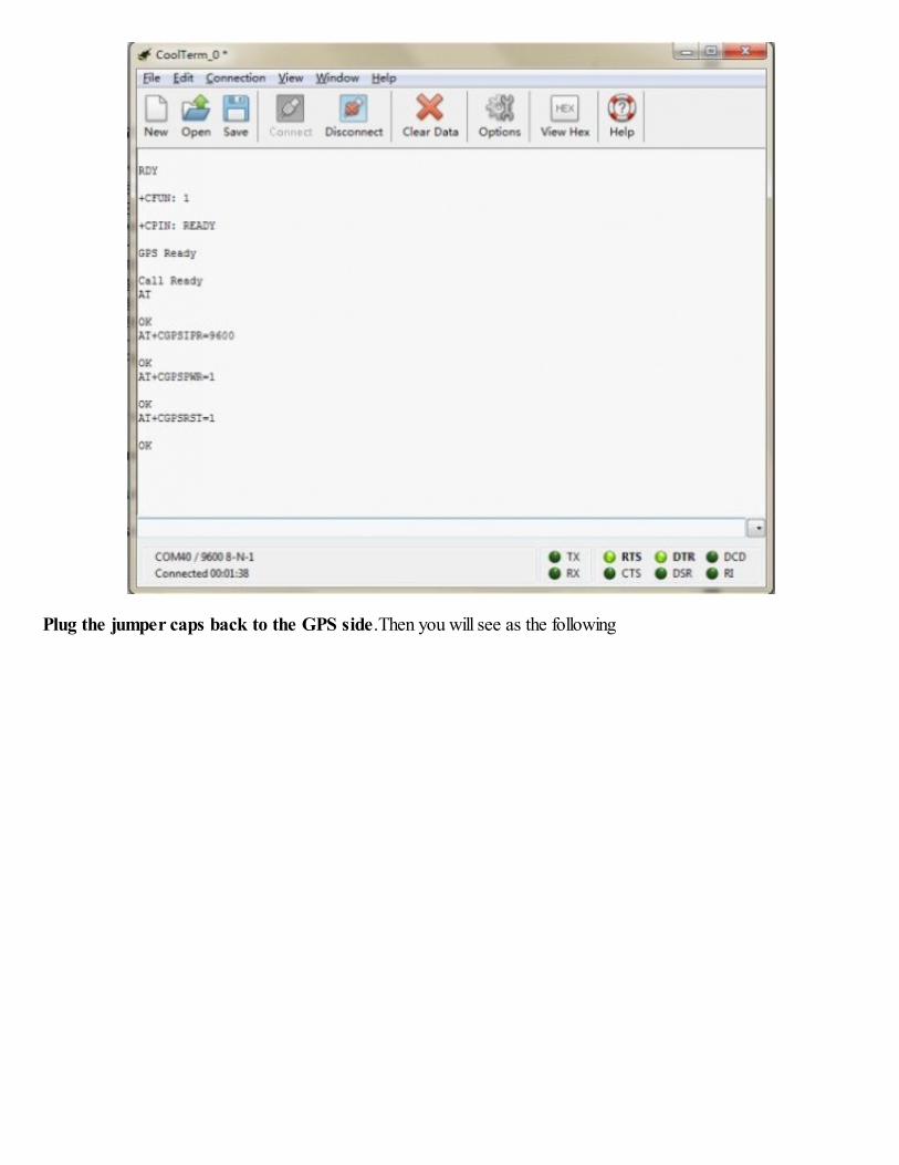
Plug the jumper caps back to the GPS side.Then you will see as the following
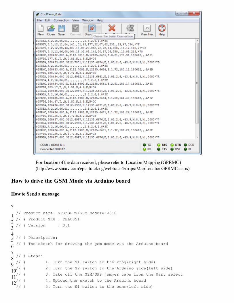
For location of the data received, please refer to Location Mapping (GPRMC)
(http://www.sanav.com/gps_tracking/webtrac-4/maps/MapLocationGPRMC.aspx)
How to drive the GSM Mode via Arduino board
How to Send a message
?
1
2
3
4
5
6
7
89
10
11
12
// Product name: GPS/GPRS/GSM Module V3.0
// # Product SKU : TEL0051
// # Version : 0.1
// # Description:
// # The sketch for driving the gsm mode via the Arduino board
// # Steps:
// # 1. Turn the S1 switch to the Prog(right side)
// # 2. Turn the S2 switch to the Arduino side(left side)
// # 3. Take off the GSM/GPS jumper caps from the Uart select
// # 4. Upload the sketch to the Arduino board
// # 5. Turn the S1 switch to the comm(left side)
13
14
15
16
17
18
1920
2122
232425
2627
2829
303132
3334
3536
373839
4041
4243
444546
4748
4950
515253
5455
5657
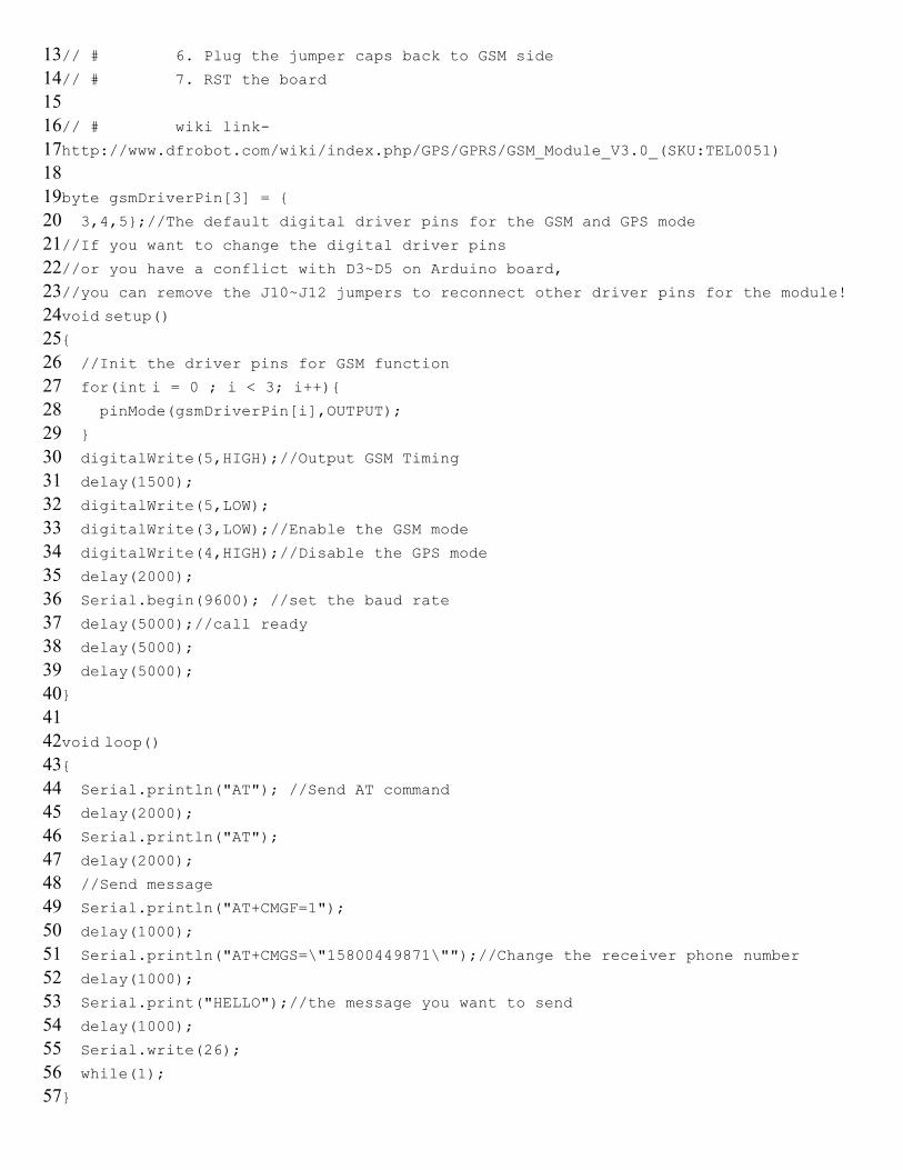
// # 6. Plug the jumper caps back to GSM side
// # 7. RST the board
// # wiki link-
http://www.dfrobot.com/wiki/index.php/GPS/GPRS/GSM_Module_V3.0_(SKU:TEL0051)
byte gsmDriverPin[3] = {
3,4,5};//The default digital driver pins for the GSM and GPS mode
//If you want to change the digital driver pins
//or you have a conflict with D3~D5 on Arduino board,
//you can remove the J10~J12 jumpers to reconnect other driver pins for the module!
void setup(){
//Init the driver pins for GSM function
for(int i = 0 ; i < 3; i++){
pinMode(gsmDriverPin[i],OUTPUT);
}
digitalWrite(5,HIGH);//Output GSM Timing
delay(1500);
digitalWrite(5,LOW);
digitalWrite(3,LOW);//Enable the GSM mode
digitalWrite(4,HIGH);//Disable the GPS mode
delay(2000);
Serial.begin(9600); //set the baud rate
delay(5000);//call ready
delay(5000);
delay(5000);
}
void loop(){
Serial.println("AT"); //Send AT command
delay(2000);
Serial.println("AT");
delay(2000);
//Send message
Serial.println("AT+CMGF=1");
delay(1000);
Serial.println("AT+CMGS=\"15800449871\"");//Change the receiver phone number
delay(1000);
Serial.print("HELLO");//the message you want to send
delay(1000);
Serial.write(26);
while(1);
}
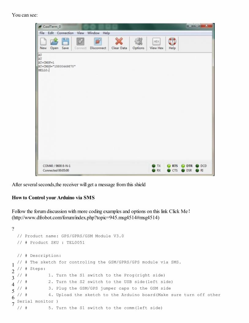
You can see:
After several seconds,the receiver will get a message from this shield
How to Control your Arduino via SMS
Follow the forum discussion with more coding examples and options on this link Click Me!(http://www.dfrobot.com/forum/index.php?topic=945.msg4514#msg4514)
?
12
345
67
// Product name: GPS/GPRS/GSM Module V3.0
// # Product SKU : TEL0051
// # Description:
// # The sketch for controling the GSM/GPRS/GPS module via SMS.
// # Steps:
// # 1. Turn the S1 switch to the Prog(right side)
// # 2. Turn the S2 switch to the USB side(left side)
// # 3. Plug the GSM/GPS jumper caps to the GSM side
// # 4. Upload the sketch to the Arduino board(Make sure turn off other
Serial monitor )
// # 5. Turn the S1 switch to the comm(left side)
8
91011
1213
1415
1617
181920
2122
2324
252627
2829
3031
323334
3536
3738
394041
4243
4445
464748
4950
5152
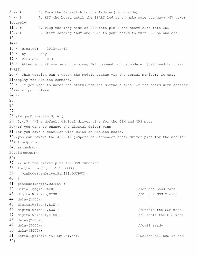
// # 6. Turn the S2 switch to the Arduino(right side)
// # 7. RST the board until the START led is on(make sure you have >6V power
supply)
// # 8. Plug the long side of LED into pin 8 and short side into GND
// # 9. Start sending "LH" and "LL" to your board to turn LED on and off.
/*
* created: 2013-11-14
* by: Grey
* Version: 0.3
* Attention: if you send the wrong SMS command to the module, just need to press
RST.
* This version can't watch the module status via the serial monitor, it only
display the Arduino command.
* If you want to watch the status,use the SoftwareSerial or the board with another
serial port plese.
*/
byte gsmDriverPin[3] = {
3,4,5};//The default digital driver pins for the GSM and GPS mode
//If you want to change the digital driver pins
//or you have a conflict with D3~D5 on Arduino board,
//you can remove the J10~J12 jumpers to reconnect other driver pins for the module!
int ledpin = 8;char inchar;
void setup(){
//Init the driver pins for GSM function
for(int i = 0 ; i < 3; i++){
pinMode(gsmDriverPin[i],OUTPUT);
}
pinMode(ledpin,OUTPUT);
Serial.begin(9600); //set the baud rate
digitalWrite(5,HIGH); //Output GSM Timing
delay(1500);
digitalWrite(5,LOW);
digitalWrite(3,LOW); //Enable the GSM mode
digitalWrite(4,HIGH); //Disable the GPS mode
delay(2000);
delay(5000); //call ready
delay(5000);
Serial.println("AT+CMGD=1,4"); //Delete all SMS in box
}
5354
555657
5859
6061
626364
6566
6768
697071
7273
7475
767778
7980
8182
8384
858687
8889
9091
92
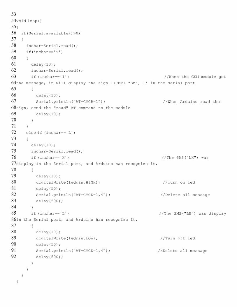
void loop()
{
if(Serial.available()>0)
{
inchar=Serial.read();
if(inchar=='T')
{
delay(10);
inchar=Serial.read();
if (inchar=='I') //When the GSM module getthe message, it will display the sign '+CMTI "SM", 1' in the serial port
{
delay(10);
Serial.println("AT+CMGR=1"); //When Arduino read the
sign, send the "read" AT command to the module
delay(10);
}
}
else if (inchar=='L') {
delay(10);
inchar=Serial.read();
if (inchar=='H') //Thw SMS("LH") wasdisplay in the Serial port, and Arduino has recognize it.
{
delay(10);
digitalWrite(ledpin,HIGH); //Turn on led
delay(50);
Serial.println("AT+CMGD=1,4"); //Delete all message
delay(500);
}
if (inchar=='L') //Thw SMS("LH") was displayin the Serial port, and Arduino has recognize it.
{
delay(10);
digitalWrite(ledpin,LOW); //Turn off led
delay(50);
Serial.println("AT+CMGD=1,4"); //Delete all message
delay(500);
}
}
}
}
When you send the SMS "LH" to the module, it WILL turn led on; when you send the SMS "LL", it will be turnedoff.
How to Make a phone call
?
1
234
56
78
91011
1213
1415
161718
1920
2122
232425
2627
2829
303132
3334
3536
3738
39
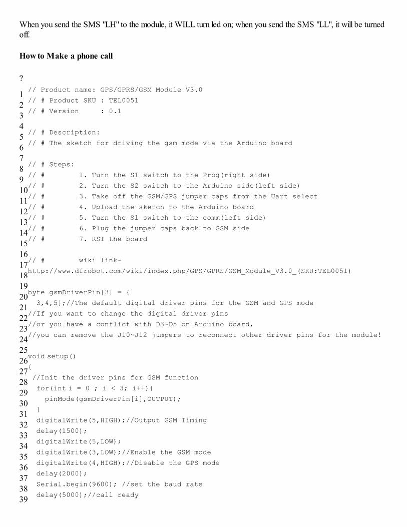
// Product name: GPS/GPRS/GSM Module V3.0
// # Product SKU : TEL0051
// # Version : 0.1
// # Description:
// # The sketch for driving the gsm mode via the Arduino board
// # Steps:
// # 1. Turn the S1 switch to the Prog(right side)
// # 2. Turn the S2 switch to the Arduino side(left side)
// # 3. Take off the GSM/GPS jumper caps from the Uart select
// # 4. Upload the sketch to the Arduino board
// # 5. Turn the S1 switch to the comm(left side)
// # 6. Plug the jumper caps back to GSM side
// # 7. RST the board
// # wiki link-
http://www.dfrobot.com/wiki/index.php/GPS/GPRS/GSM_Module_V3.0_(SKU:TEL0051)
byte gsmDriverPin[3] = {
3,4,5};//The default digital driver pins for the GSM and GPS mode
//If you want to change the digital driver pins
//or you have a conflict with D3~D5 on Arduino board,
//you can remove the J10~J12 jumpers to reconnect other driver pins for the module!
void setup(){
//Init the driver pins for GSM function
for(int i = 0 ; i < 3; i++){ pinMode(gsmDriverPin[i],OUTPUT);
}
digitalWrite(5,HIGH);//Output GSM Timing
delay(1500);
digitalWrite(5,LOW);
digitalWrite(3,LOW);//Enable the GSM mode
digitalWrite(4,HIGH);//Disable the GPS mode
delay(2000);
Serial.begin(9600); //set the baud rate
delay(5000);//call ready
4041
424344
4546
4748
495051
52
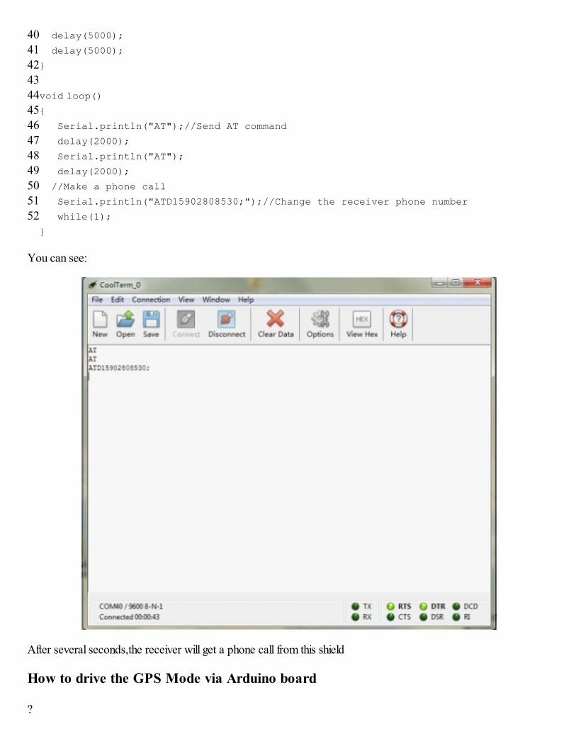
delay(5000);
delay(5000);
}
void loop()
{
Serial.println("AT");//Send AT command
delay(2000);
Serial.println("AT");
delay(2000);
//Make a phone call
Serial.println("ATD15902808530;");//Change the receiver phone number
while(1);
}
You can see:
After several seconds,the receiver will get a phone call from this shield
How to drive the GPS Mode via Arduino board
?
12
345
67
89
101112
1314
1516
171819
2021
2223
242526
2728
2930
313233
3435
3637
383940
4142
4344
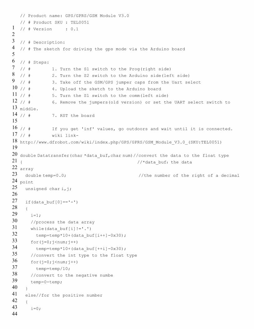
// Product name: GPS/GPRS/GSM Module V3.0
// # Product SKU : TEL0051
// # Version : 0.1
// # Description:
// # The sketch for driving the gps mode via the Arduino board
// # Steps:
// # 1. Turn the S1 switch to the Prog(right side)
// # 2. Turn the S2 switch to the Arduino side(left side)
// # 3. Take off the GSM/GPS jumper caps from the Uart select
// # 4. Upload the sketch to the Arduino board
// # 5. Turn the S1 switch to the comm(left side)
// # 6. Remove the jumpers(old version) or set the UART select switch to
middle.
// # 7. RST the board
// # If you get 'inf' values, go outdoors and wait until it is connected.
// # wiki link-
http://www.dfrobot.com/wiki/index.php/GPS/GPRS/GSM_Module_V3.0_(SKU:TEL0051)
double Datatransfer(char *data_buf,char num)//convert the data to the float type
{ //*data_buf:the data
array
double temp=0.0; //the number of the right of a decimalpoint
unsigned char i,j;
if(data_buf[0]=='-')
{
i=1;
//process the data array
while(data_buf[i]!='.')
temp=temp*10+(data_buf[i++]-0x30);
for(j=0;j<num;j++)
temp=temp*10+(data_buf[++i]-0x30);
//convert the int type to the float type
for(j=0;j<num;j++)
temp=temp/10;
//convert to the negative numbe
temp=0-temp;
}
else//for the positive number
{
i=0;
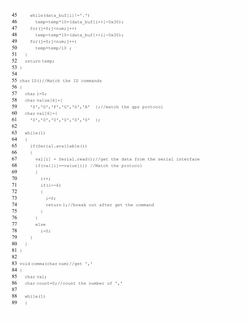
4546
474849
5051
5253
545556
5758
5960
616263
6465
6667
686970
7172
7374
757677
7879
8081
828384
8586
8788
89
while(data_buf[i]!='.')
temp=temp*10+(data_buf[i++]-0x30);
for(j=0;j<num;j++)
temp=temp*10+(data_buf[++i]-0x30);
for(j=0;j<num;j++)
temp=temp/10 ;
}
return temp;}
char ID()//Match the ID commands{
char i=0; char value[6]={
'$','G','P','G','G','A' };//match the gps protocol char val[6]={
'0','0','0','0','0','0' }; while(1)
{
if(Serial.available())
{
val[i] = Serial.read();//get the data from the serial interface
if(val[i]==value[i]) //Match the protocol
{
i++;
if(i==6)
{
i=0;
return 1;//break out after get the command
}
}
else
i=0;
}
}
}
void comma(char num)//get ','{
char val; char count=0;//count the number of ','
while(1)
{
90
919293
9495
9697
9899100
101102
103104
105106107
108109
110111
112113
114115116
117118
119120
121122123
124125
126127
128129130
131132
133134
if(Serial.available())
{
val = Serial.read();
if(val==',')
count++;
}
if(count==num)//if the command is right, run return
return;
}
}
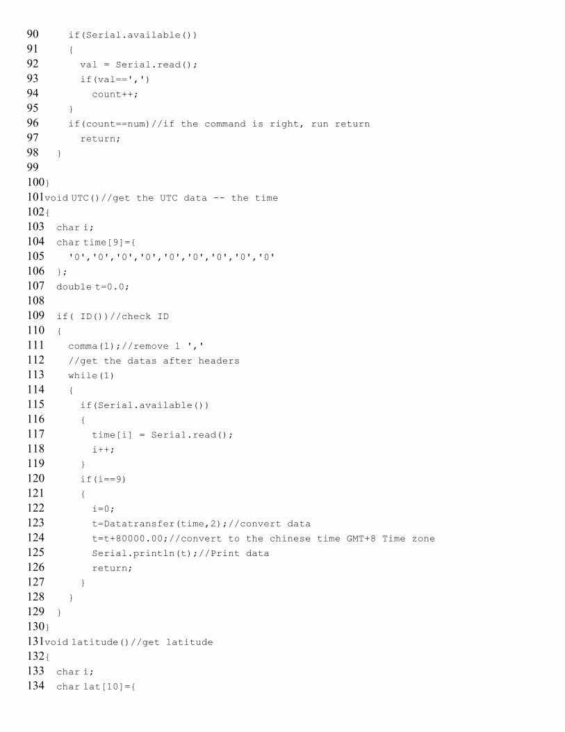
void UTC()//get the UTC data -- the time{
char i; char time[9]={
'0','0','0','0','0','0','0','0','0'
};
double t=0.0;
if( ID())//check ID
{
comma(1);//remove 1 ','
//get the datas after headers
while(1)
{
if(Serial.available())
{
time[i] = Serial.read();
i++;
}
if(i==9)
{
i=0;
t=Datatransfer(time,2);//convert data
t=t+80000.00;//convert to the chinese time GMT+8 Time zone
Serial.println(t);//Print data
return;
}
}
}
}
void latitude()//get latitude{
char i; char lat[10]={
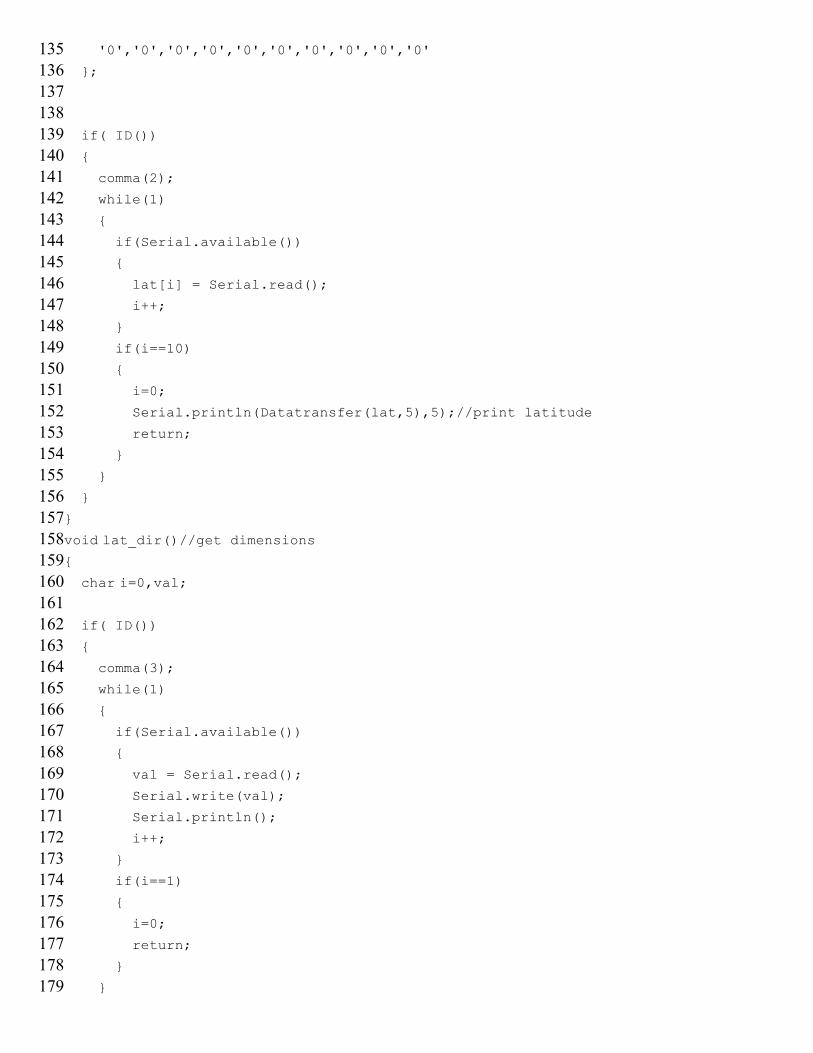
135136
137138139
140141
142143
144145146
147148
149150
151152153
154155
156157
158159160
161162
163164
165166167
168169
170171
172173174
175176
177178
179
'0','0','0','0','0','0','0','0','0','0'
};
if( ID())
{
comma(2);
while(1)
{
if(Serial.available())
{
lat[i] = Serial.read();
i++;
}
if(i==10)
{
i=0;
Serial.println(Datatransfer(lat,5),5);//print latitude
return;
}
}
}
}
void lat_dir()//get dimensions{
char i=0,val;
if( ID())
{
comma(3);
while(1)
{
if(Serial.available())
{
val = Serial.read();
Serial.write(val);
Serial.println();
i++;
}
if(i==1)
{
i=0;
return;
}
}
180
181182183
184185
186187
188189190
191192
193194
195196197
198199
200201
202203204
205206
207208
209210
211212213
214215
216217
218219220
221222
223224
}
}
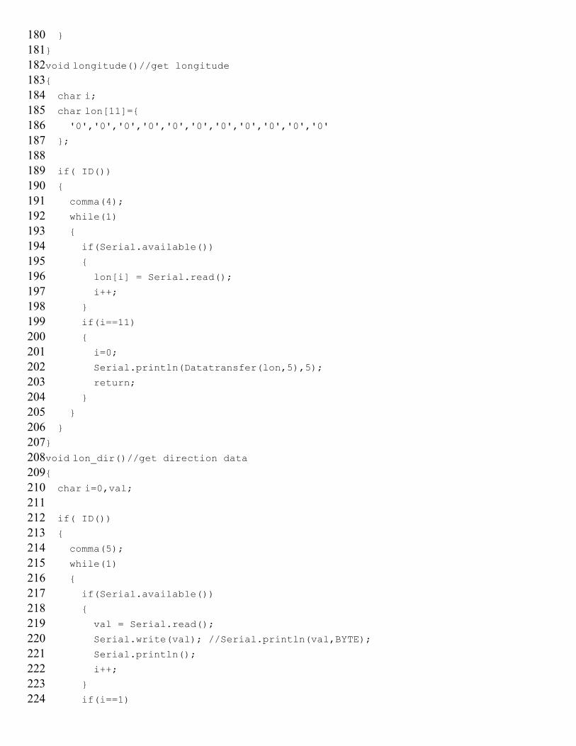
void longitude()//get longitude{
char i; char lon[11]={
'0','0','0','0','0','0','0','0','0','0','0'
};
if( ID())
{
comma(4);
while(1)
{
if(Serial.available())
{
lon[i] = Serial.read();
i++;
}
if(i==11)
{
i=0;
Serial.println(Datatransfer(lon,5),5);
return;
}
}
}
}
void lon_dir()//get direction data
{
char i=0,val;
if( ID())
{
comma(5);
while(1)
{
if(Serial.available())
{
val = Serial.read();
Serial.write(val); //Serial.println(val,BYTE);
Serial.println();
i++;
}
if(i==1)
225226227
228229
230231
232233
234235236
237238239
240241242243244
245246247248249
250251252253
254255256257258
259260261262
263264265266267
268269
{
i=0;
return;
}
}
}
}
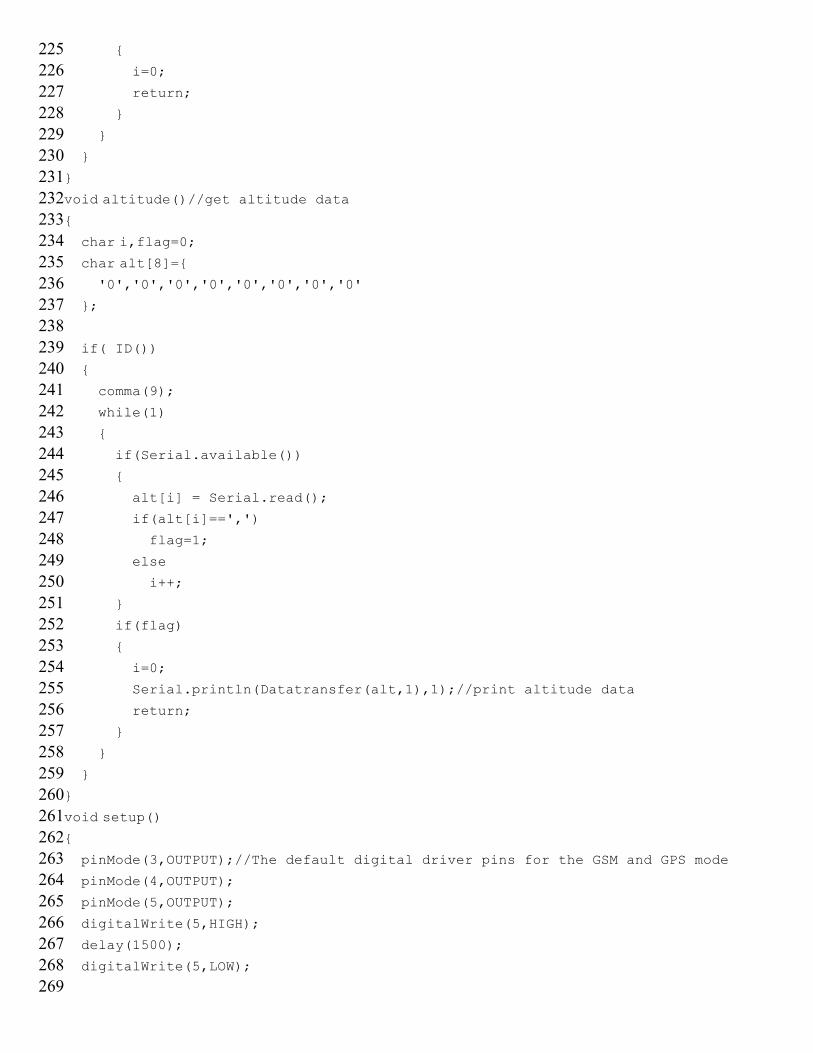
void altitude()//get altitude data{
char i,flag=0; char alt[8]={ '0','0','0','0','0','0','0','0'
};
if( ID())
{
comma(9);
while(1)
{
if(Serial.available())
{
alt[i] = Serial.read();
if(alt[i]==',')
flag=1;
else
i++;
}
if(flag)
{
i=0;
Serial.println(Datatransfer(alt,1),1);//print altitude data
return;
}
}
}
}
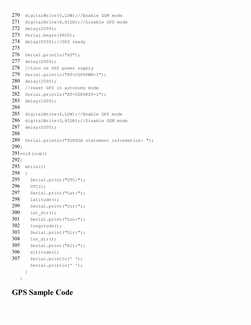
void setup(){
pinMode(3,OUTPUT);//The default digital driver pins for the GSM and GPS mode
pinMode(4,OUTPUT);
pinMode(5,OUTPUT);
digitalWrite(5,HIGH);
delay(1500);
digitalWrite(5,LOW);
270271272
273274275276
277278279280281
282283284285
286287288289290
291292293294295
296297298299
300301302303304
305306307
digitalWrite(3,LOW);//Enable GSM mode
digitalWrite(4,HIGH);//Disable GPS mode
delay(2000);
Serial.begin(9600);
delay(5000);//GPS ready
Serial.println("AT");
delay(2000);
//turn on GPS power supply
Serial.println("AT+CGPSPWR=1");
delay(1000);
//reset GPS in autonomy mode
Serial.println("AT+CGPSRST=1");
delay(1000);
digitalWrite(4,LOW);//Enable GPS mode
digitalWrite(3,HIGH);//Disable GSM mode
delay(2000);
Serial.println("$GPGGA statement information: ");
}
void loop(){
while(1)
{
Serial.print("UTC:");
UTC();
Serial.print("Lat:");
latitude();
Serial.print("Dir:");
lat_dir();
Serial.print("Lon:");
longitude();
Serial.print("Dir:");
lon_dir();
Serial.print("Alt:");
altitude();
Serial.println(' ');
Serial.println(' ');
}
}
GPS Sample Code
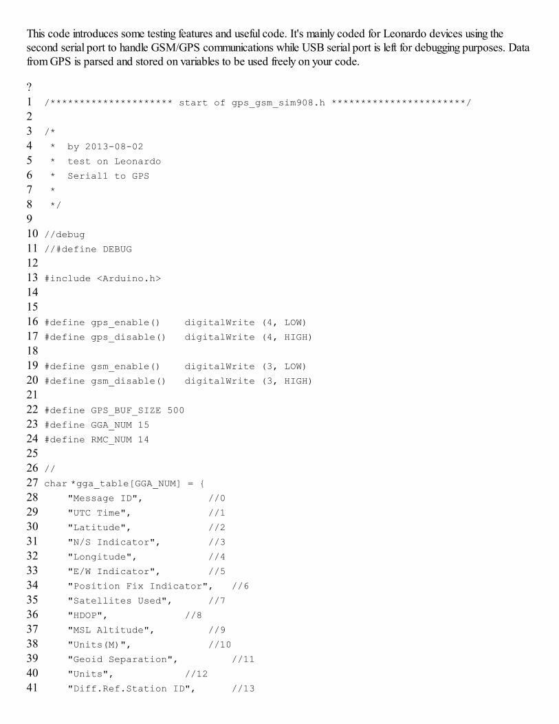
This code introduces some testing features and useful code. It's mainly coded for Leonardo devices using thesecond serial port to handle GSM/GPS communications while USB serial port is left for debugging purposes. Datafrom GPS is parsed and stored on variables to be used freely on your code.
?1
2345
678910
1112131415
16171819
2021222324
2526272829
30313233
3435363738
394041
/********************* start of gps_gsm_sim908.h ***********************/
/*
* by 2013-08-02
* test on Leonardo
* Serial1 to GPS
*
*/
//debug
//#define DEBUG
#include <Arduino.h>
#define gps_enable() digitalWrite (4, LOW)
#define gps_disable() digitalWrite (4, HIGH)
#define gsm_enable() digitalWrite (3, LOW)
#define gsm_disable() digitalWrite (3, HIGH)
#define GPS_BUF_SIZE 500
#define GGA_NUM 15
#define RMC_NUM 14
//
char *gga_table[GGA_NUM] = { "Message ID", //0
"UTC Time", //1
"Latitude", //2
"N/S Indicator", //3
"Longitude", //4
"E/W Indicator", //5
"Position Fix Indicator", //6
"Satellites Used", //7
"HDOP", //8
"MSL Altitude", //9
"Units(M)", //10
"Geoid Separation", //11
"Units", //12
"Diff.Ref.Station ID", //13

4243444546
4748495051
52535455
5657585960
61626364
6566676869
7071727374
75767778
7980818283
848586
"Checksum", //14
};
//
char *gprmc_table[RMC_NUM] = {
"Message ID", //0
"UTC Time", //1
"Status", //2
"Latitude", //3
"N/S Indicator", //4
"Langitude", //5
"E/W Indicator", //6
"Speed Over Ground", //7
"Course Over Ground", //8
"Date", //9
"Magnetic Variation", //10
"East/West Indicator", //11
"Mode", //12
"Checksum", //13
};
//save data from GPS
uint8_t gps_buf[GPS_BUF_SIZE];
//save pointer of gga block
uint8_t* gga_p[GGA_NUM];
uint8_t* gprmc_p[RMC_NUM];
// check sum using xor
uint8_t checksum_xor (uint8_t *array, uint8_t leng) {
uint8_t sum = array[0];
for (uint8_t i=1; i<leng; i++) {
sum ̂= array[i];
}
return sum;}
//
void start_gps () { digitalWrite (5, HIGH);
delay (1500);
digitalWrite (5, LOW);
delay (1500);
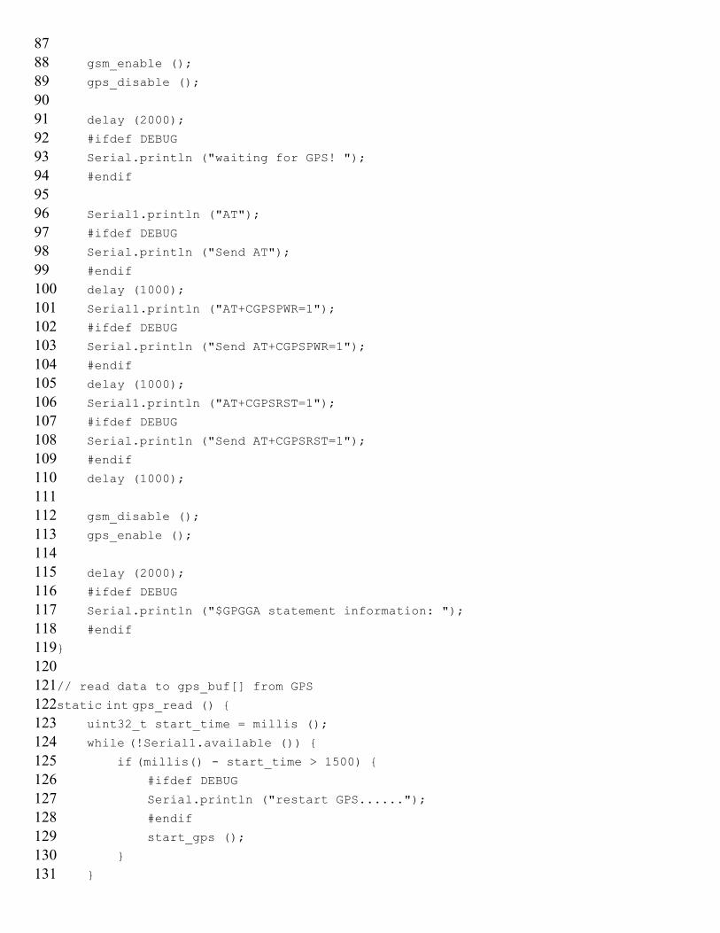
87
8889909192
9394959697
9899100101
102103104105106
107108109110111
112113114115
116117118119120
121122123124125
126127128129
130131
gsm_enable ();
gps_disable ();
delay (2000);
#ifdef DEBUG
Serial.println ("waiting for GPS! ");
#endif
Serial1.println ("AT");
#ifdef DEBUG
Serial.println ("Send AT");
#endif
delay (1000);
Serial1.println ("AT+CGPSPWR=1");
#ifdef DEBUG
Serial.println ("Send AT+CGPSPWR=1");
#endif
delay (1000);
Serial1.println ("AT+CGPSRST=1");
#ifdef DEBUG
Serial.println ("Send AT+CGPSRST=1");
#endif
delay (1000);
gsm_disable ();
gps_enable ();
delay (2000);
#ifdef DEBUG
Serial.println ("$GPGGA statement information: ");
#endif
}
// read data to gps_buf[] from GPS
static int gps_read () { uint32_t start_time = millis ();
while (!Serial1.available ()) { if (millis() - start_time > 1500) {
#ifdef DEBUG
Serial.println ("restart GPS......");
#endif
start_gps ();
}
}
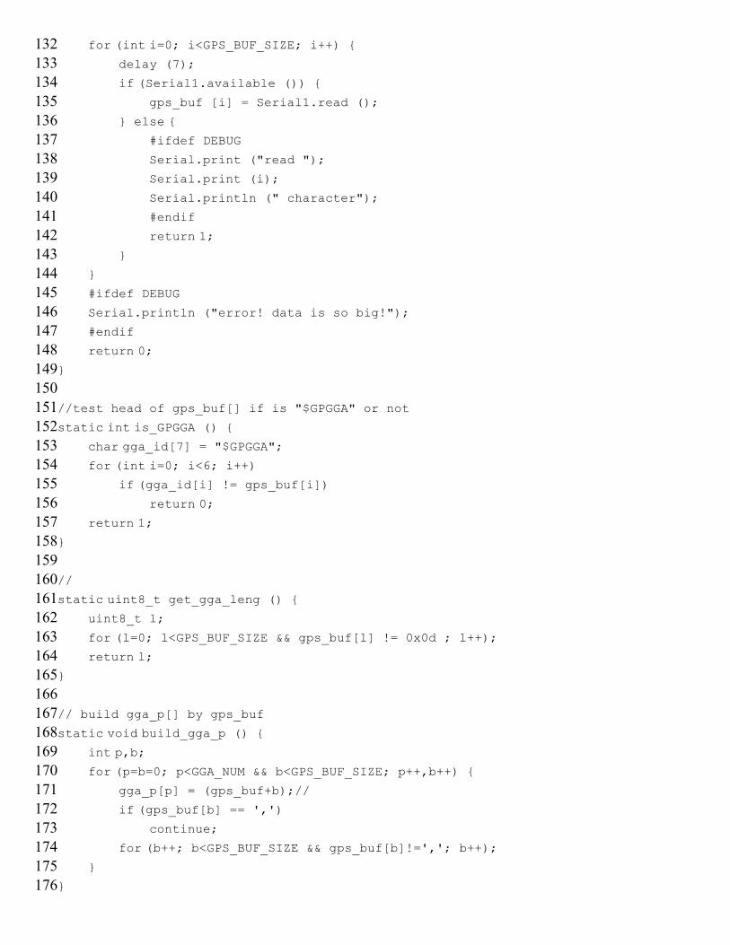
132133134
135136137138
139140141142143
144145146147148
149150151152
153154155156157
158159160161
162163164165166
167168169170171
172173174175
176
for (int i=0; i<GPS_BUF_SIZE; i++) { delay (7);
if (Serial1.available ()) {
gps_buf [i] = Serial1.read ();
} else { #ifdef DEBUG
Serial.print ("read ");
Serial.print (i);
Serial.println (" character");
#endif
return 1; }
}
#ifdef DEBUG
Serial.println ("error! data is so big!");
#endif
return 0;
}
//test head of gps_buf[] if is "$GPGGA" or not
static int is_GPGGA () {
char gga_id[7] = "$GPGGA"; for (int i=0; i<6; i++) if (gga_id[i] != gps_buf[i]) return 0; return 1;
}
//
static uint8_t get_gga_leng () {
uint8_t l;
for (l=0; l<GPS_BUF_SIZE && gps_buf[l] != 0x0d ; l++); return l;}
// build gga_p[] by gps_buf
static void build_gga_p () { int p,b; for (p=b=0; p<GGA_NUM && b<GPS_BUF_SIZE; p++,b++) { gga_p[p] = (gps_buf+b);//
if (gps_buf[b] == ',') continue;
for (b++; b<GPS_BUF_SIZE && gps_buf[b]!=','; b++); }
}
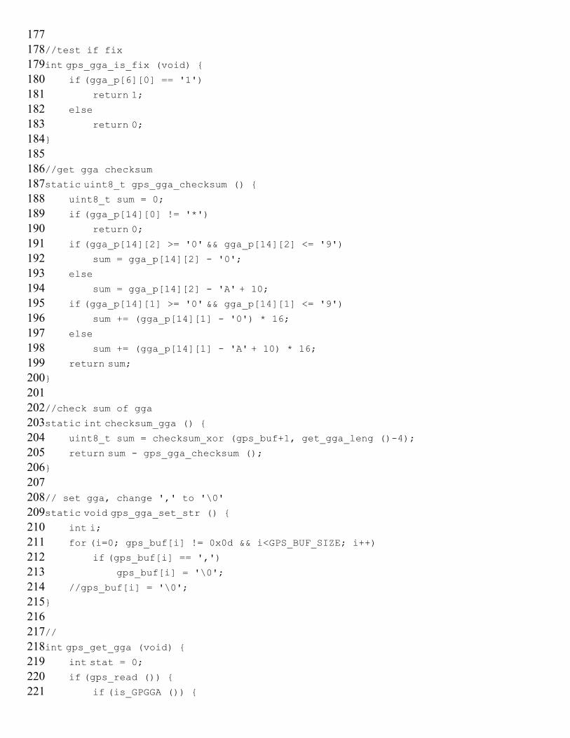
177178179180
181182183184
185186187188189
190191192193194
195196197198
199200201202203
204205206207208
209210211212
213214215216217
218219220221
//test if fix
int gps_gga_is_fix (void) { if (gga_p[6][0] == '1')
return 1; else
return 0;}
//get gga checksum
static uint8_t gps_gga_checksum () { uint8_t sum = 0;
if (gga_p[14][0] != '*')
return 0; if (gga_p[14][2] >= '0' && gga_p[14][2] <= '9') sum = gga_p[14][2] - '0';
else
sum = gga_p[14][2] - 'A' + 10;
if (gga_p[14][1] >= '0' && gga_p[14][1] <= '9') sum += (gga_p[14][1] - '0') * 16;
else
sum += (gga_p[14][1] - 'A' + 10) * 16;
return sum;}
//check sum of gga
static int checksum_gga () {
uint8_t sum = checksum_xor (gps_buf+1, get_gga_leng ()-4);
return sum - gps_gga_checksum ();}
// set gga, change ',' to '\0'
static void gps_gga_set_str () { int i; for (i=0; gps_buf[i] != 0x0d && i<GPS_BUF_SIZE; i++) if (gps_buf[i] == ',')
gps_buf[i] = '\0';
//gps_buf[i] = '\0';
}
//
int gps_get_gga (void) { int stat = 0; if (gps_read ()) { if (is_GPGGA ()) {
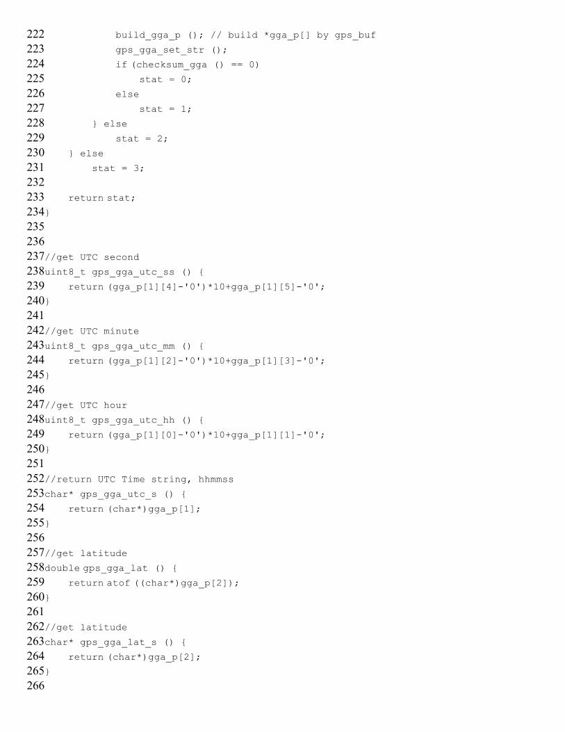
222223224225226
227228229230231
232233234235
236237238239240
241242243244245
246247248249
250251252253254
255256257258
259260261262263
264265266
build_gga_p (); // build *gga_p[] by gps_buf
gps_gga_set_str ();
if (checksum_gga () == 0) stat = 0;
else
stat = 1;
} else
stat = 2;
} else
stat = 3;
return stat;}
//get UTC second
uint8_t gps_gga_utc_ss () {
return (gga_p[1][4]-'0')*10+gga_p[1][5]-'0';}
//get UTC minute
uint8_t gps_gga_utc_mm () {
return (gga_p[1][2]-'0')*10+gga_p[1][3]-'0';}
//get UTC hour
uint8_t gps_gga_utc_hh () {
return (gga_p[1][0]-'0')*10+gga_p[1][1]-'0';
}
//return UTC Time string, hhmmss
char* gps_gga_utc_s () {
return (char*)gga_p[1];
}
//get latitude
double gps_gga_lat () {
return atof ((char*)gga_p[2]);}
//get latitude
char* gps_gga_lat_s () {
return (char*)gga_p[2];}
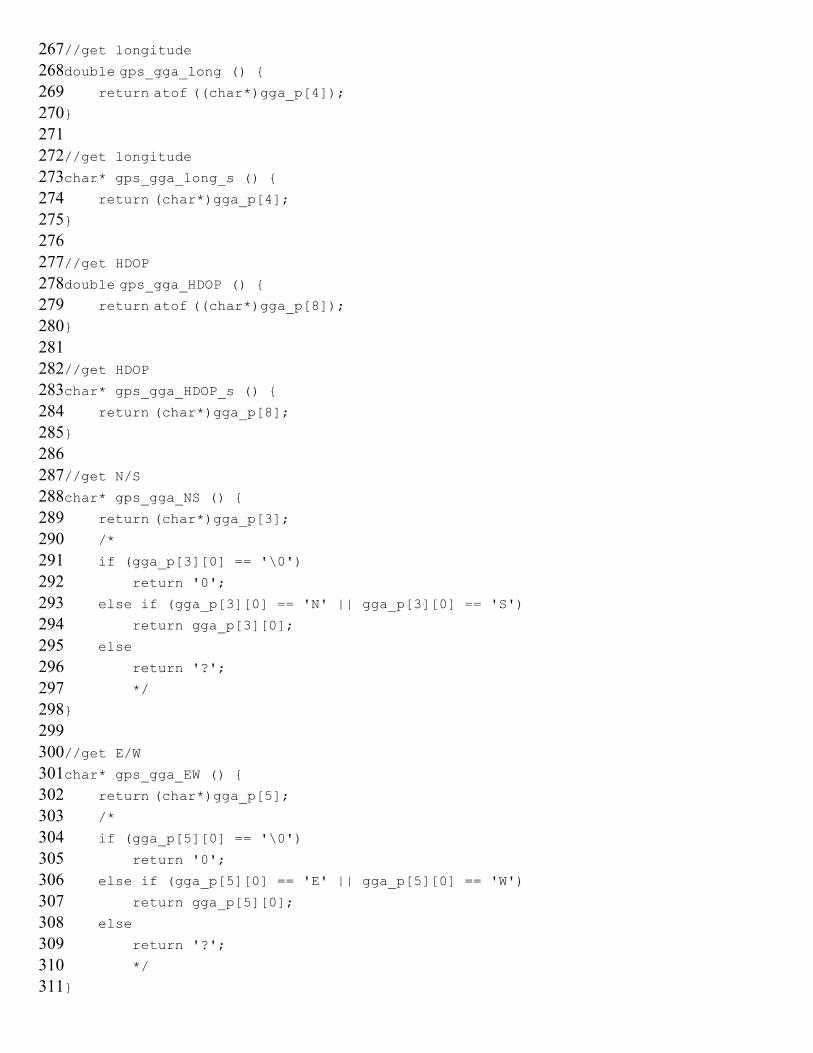
267268
269270271272
273274275276277
278279280281
282283284285286
287288289290291
292293294295
296297298299300
301302303304305
306307308309
310311
//get longitude
double gps_gga_long () {
return atof ((char*)gga_p[4]);}
//get longitude
char* gps_gga_long_s () {
return (char*)gga_p[4];}
//get HDOP
double gps_gga_HDOP () { return atof ((char*)gga_p[8]);}
//get HDOP
char* gps_gga_HDOP_s () {
return (char*)gga_p[8];}
//get N/S
char* gps_gga_NS () {
return (char*)gga_p[3]; /*
if (gga_p[3][0] == '\0')
return '0';
else if (gga_p[3][0] == 'N' || gga_p[3][0] == 'S')
return gga_p[3][0];
else
return '?';
*/
}
//get E/W
char* gps_gga_EW () {
return (char*)gga_p[5]; /*
if (gga_p[5][0] == '\0')
return '0';
else if (gga_p[5][0] == 'E' || gga_p[5][0] == 'W')
return gga_p[5][0];
else
return '?';
*/
}
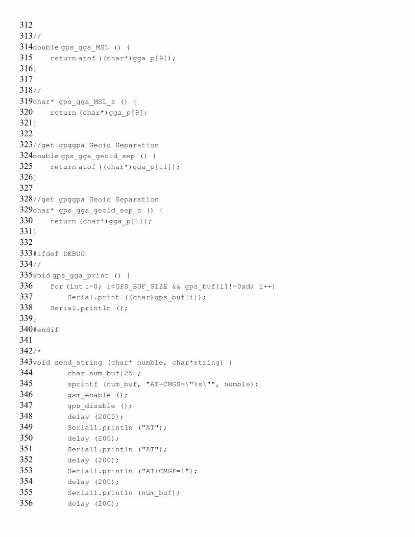
312313314
315316317318
319320321322323
324325326327328
329330331332
333334335336337
338339340341342
343344345346
347348349350351
352353354355
356
//
double gps_gga_MSL () {
return atof ((char*)gga_p[9]);}
//
char* gps_gga_MSL_s () {
return (char*)gga_p[9];}
//get gpggpa Geoid Separation
double gps_gga_geoid_sep () { return atof ((char*)gga_p[11]);}
//get gpggpa Geoid Separation
char* gps_gga_geoid_sep_s () {
return (char*)gga_p[11];}
#ifdef DEBUG
//
void gps_gga_print () { for (int i=0; i<GPS_BUF_SIZE && gps_buf[i]!=0xd; i++) Serial.print ((char)gps_buf[i]);
Serial.println ();
}
#endif
/*
void send_string (char* numble, char*string) {
char num_buf[25];
sprintf (num_buf, "AT+CMGS=\"%s\"", numble);
gsm_enable ();
gps_disable ();
delay (2000);
Serial1.println ("AT");
delay (200);
Serial1.println ("AT");
delay (200);
Serial1.println ("AT+CMGF=1");
delay (200);
Serial1.println (num_buf);
delay (200);
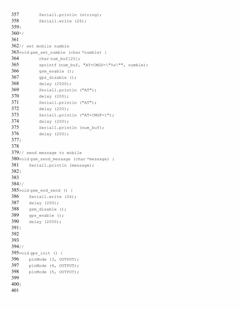
357358359360
361362363364365
366367368369
370371372373374
375376377378
379380381382383
384385386387388
389390391392
393394395396397
398399400401
Serial1.println (string);
Serial1.write (26);
}
*/
// set mobile numble
void gsm_set_numble (char *numble) { char num_buf[25]; sprintf (num_buf, "AT+CMGS=\"%s\"", numble);
gsm_enable ();
gps_disable ();
delay (2000);
Serial1.println ("AT");
delay (200);
Serial1.println ("AT");
delay (200);
Serial1.println ("AT+CMGF=1");
delay (200);
Serial1.println (num_buf);
delay (200);
}
// send message to mobile
void gsm_send_message (char *message) { Serial1.println (message);
}
//
void gsm_end_send () { Serial1.write (26);
delay (200);
gsm_disable ();
gps_enable ();
delay (2000);
}
//
void gps_init () { pinMode (3, OUTPUT);
pinMode (4, OUTPUT);
pinMode (5, OUTPUT);
}
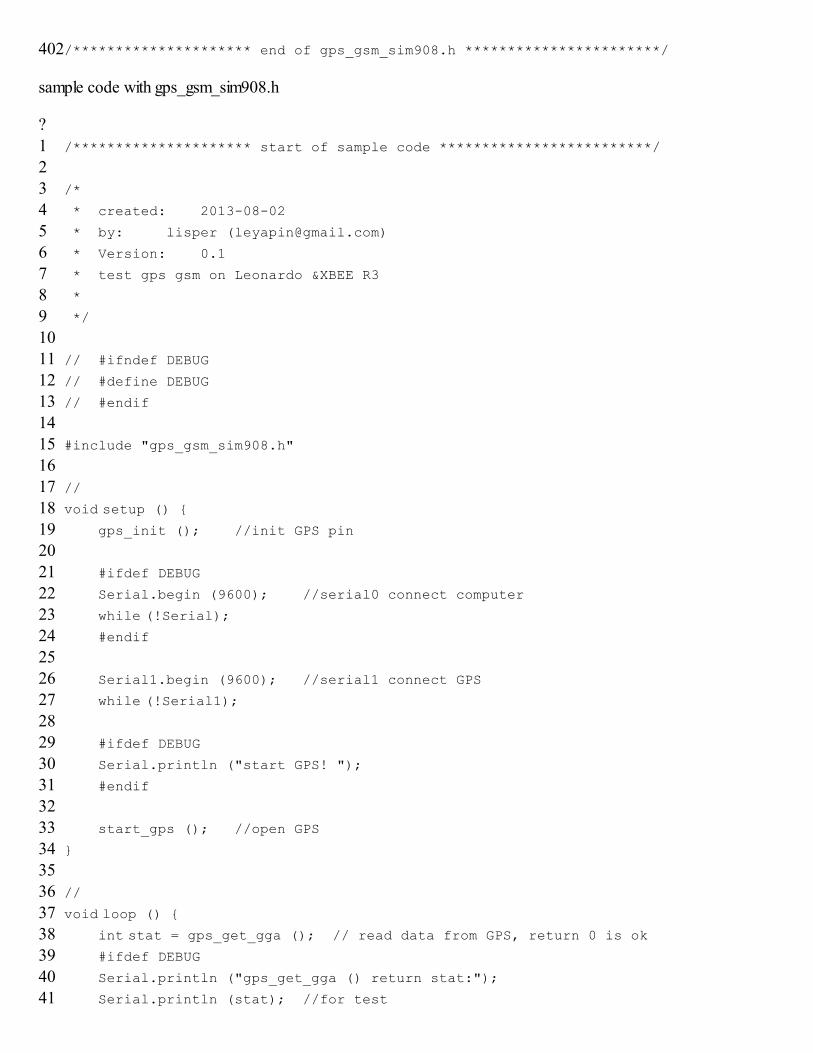
402/********************* end of gps_gsm_sim908.h ***********************/
sample code with gps_gsm_sim908.h
?123
4567
89101112
1314151617
18192021
2223242526
27282930
3132333435
3637383940
41
/********************* start of sample code *************************/
/*
* created: 2013-08-02
* by: lisper ([email protected])
* Version: 0.1
* test gps gsm on Leonardo &XBEE R3
*
*/
// #ifndef DEBUG
// #define DEBUG
// #endif
#include "gps_gsm_sim908.h"
//
void setup () { gps_init (); //init GPS pin
#ifdef DEBUG
Serial.begin (9600); //serial0 connect computer
while (!Serial); #endif
Serial1.begin (9600); //serial1 connect GPS
while (!Serial1); #ifdef DEBUG
Serial.println ("start GPS! ");
#endif
start_gps (); //open GPS
}
//
void loop () { int stat = gps_get_gga (); // read data from GPS, return 0 is ok #ifdef DEBUG
Serial.println ("gps_get_gga () return stat:");
Serial.println (stat); //for test
4243
44454647
4849505152
5354555657
58596061
6263646566
67686970
7172737475
7677787980
81828384
8586
#endif
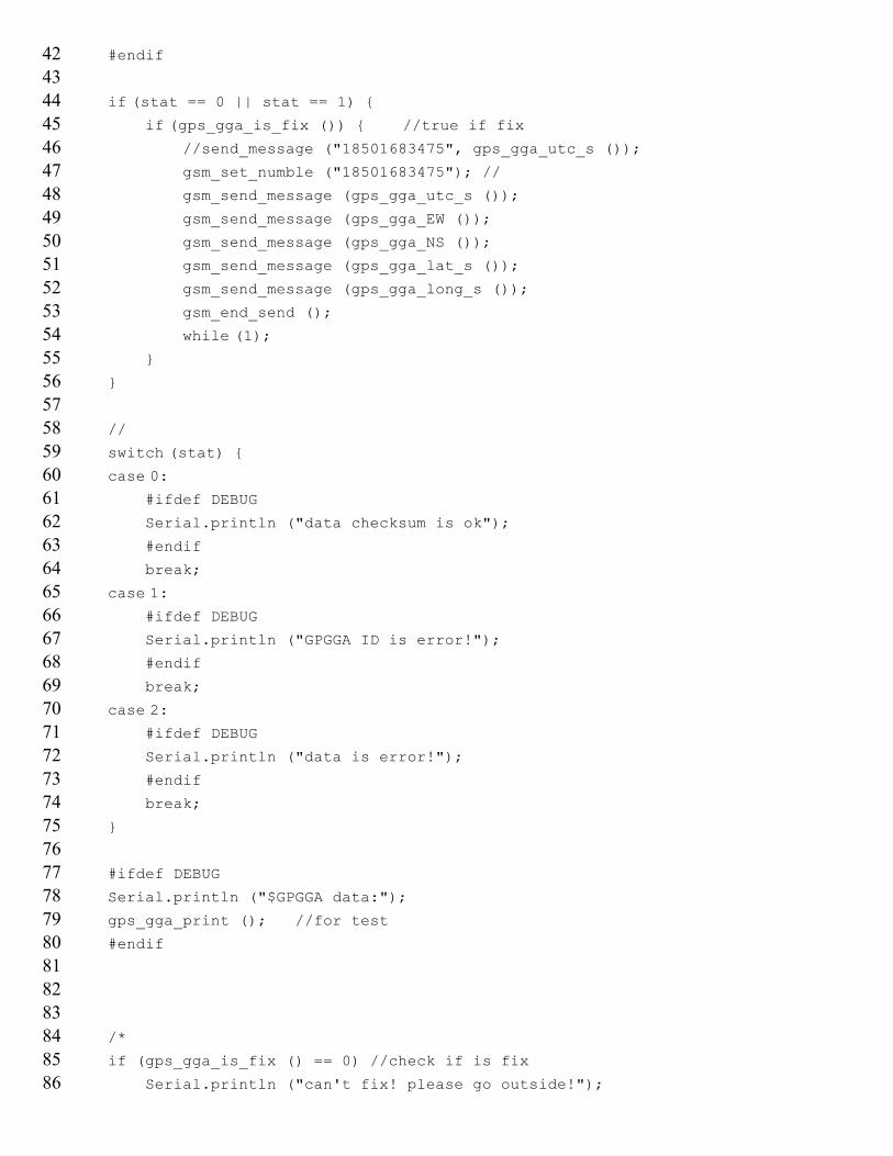
if (stat == 0 || stat == 1) { if (gps_gga_is_fix ()) { //true if fix //send_message ("18501683475", gps_gga_utc_s ());
gsm_set_numble ("18501683475"); //
gsm_send_message (gps_gga_utc_s ());
gsm_send_message (gps_gga_EW ());
gsm_send_message (gps_gga_NS ());
gsm_send_message (gps_gga_lat_s ());
gsm_send_message (gps_gga_long_s ());
gsm_end_send ();
while (1); }
}
//
switch (stat) { case 0: #ifdef DEBUG
Serial.println ("data checksum is ok");
#endif
break;
case 1: #ifdef DEBUG
Serial.println ("GPGGA ID is error!");
#endif
break;
case 2:
#ifdef DEBUG
Serial.println ("data is error!");
#endif
break;
}
#ifdef DEBUG
Serial.println ("$GPGGA data:");
gps_gga_print (); //for test
#endif
/*
if (gps_gga_is_fix () == 0) //check if is fix
Serial.println ("can't fix! please go outside!");
878889
90919293
9495969798
99100101102103
104105106107
108109110111112
113114115116
else {
Serial.println ("ok! is fix!");
Serial.println ("gps_gga_utc_hh ()");
Serial.println (gps_gga_utc_hh ());
Serial.println ("gps_gga_utc_mm ()");
Serial.println (gps_gga_utc_mm ());
Serial.println ("gps_gga_utc_ss ()");
Serial.println (gps_gga_utc_ss ());
Serial.println ("gps_gga_NS ()");
Serial.println (gps_gga_NS (), 6);
Serial.println ("gps_gga_EW ()");
Serial.println (gps_gga_EW (), 6);
Serial.println ("gps_gga_lat ()");
Serial.println (gps_gga_lat (), 6);
Serial.println ("gps_gga_long ()");
Serial.println (gps_gga_long (), 6);
Serial.println ("gps_gga_HDOP ()");
Serial.println (gps_gga_HDOP (), 6);
Serial.println ("gps_gga_MSL ()");
Serial.println (gps_gga_MSL (), 6);
Serial.println ();
}
*/
}
/********************* end of sample code *************************/
Trouble shooting
Check external battery power levels, the shield needs extra power.Check signal range, best to be on an area with full coverage.Signal for GPS has best performance on a clear direct line of sight with sky, even better with less buildingsaround.GPS needs time to connect to at least 4 satellites to output data.
AT command tester by one of our contributors.(http://www.dfrobot.com/wiki/index.php/AT_command_tester)
Version history
GPS/GPRS/GSM Module V2.0 (SKU:TEL0051)
(http://www.dfrobot.com/wiki/index.php/GPS/GPRS/GSM_Module_V2.0_(SKU:TEL0051))
Go Shopping GPS/GPRS/GSM Shield V3.0 (Arduino Compatible)(SKU:TEL0051)
(http://www.dfrobot.com/index.php?route=product/product&filter_name=gps&product_id=673)
Retrieved from "http://www.dfrobot.com/wiki/index.php?title=GPS/GPRS/GSM_Module_V3.0_(SKU:TEL0051)&oldid=26181"Categories: Product Manual TEL Series Shield
This page was last modified on 10 March 2014, at 12:41.
This page has been accessed 19,272 times.