Embed Size (px)
Citation preview

GPRS-Protocols and aspects of the air interface page137
Rohde & Schwarz Trainingcenter, V 1.0
9. Protocols and aspects of the GPRS air interface
Following the description of the physical and logical channels, as well as the usedburst type and the mapping of the logical channels onto a multiframe structure,chapter shall give some details about the data transfer on the GPRS air interface.Furthermore it describes the used strategies, protocols and functions used thereby.Referencing to the chapter about the transmission planes, this block dives into thephysical layer and the RLC/MAC-layer. Thereby is no distinction taken betweentransfer of signalling messages and transfer of traffic data.
The packet switched mode requires new concepts on the air interface, on one side,the data throughput rate has to be enhanced, on the other side we have to fulfil theintegration of packet data transfer. This elicits of course consequences for the datatransfer mode on the air interface. About GSM we have to change the protocol stack,the procedures of channel allocation as well as channel access. This chapterdescribes the exchange of packet data units between the application side LLC andthe network are exchanged via the air interface.
Figure: Protocol stack on the air interface
9.1. The Physical Link Layer in GPRS
This paragraph shall give some information about the physical layer in more details.First it has to be distinguished between the physical link layer and the physical RFlayer. The physical RF has the same tasks and functions as its counterpart of GSM,or in other words, it stays the same. The modulation scheme GMSK and the usedcarrier frequencies do not change. Only modification in this part will be the multislotability, the bundling of timeslots. The physical link layer shall convey the packets ofthe RLC/MAC-layer via the air interface.
Main task of the Physical Link Layer is the date transport over the air interface, e.g.traffic data being present as LLC frames or signalling information in RLC/MAC units.It guarantees by this way the physical connection between the MS and the network.
Um Network
LLC(Note)
RLC
MAC
Phys. Link
Phys. RF
LLC
RLC
MAC
Phys. Link
Phys. RF
MS

GPRS-Protocols and aspects of the air interface page138
Rohde & Schwarz Trainingcenter, V 1.0
Tasks of the Physical Link Layer:
♦ Block Coding:Block coding is the insertion of Control Bits in the burst structure, e.g. the UplinkState Flag USF or the Parity Check Bits.
♦ Forward Error Correction, FECEnables the detection and the correction of transmission errors. The forward errorcorrection is done with the aid of the presented convolutional coder, incidentallythe same as used in GSM, and the different Coding Schemes CS1-4.
Figure: Example of Convolutional coder
The convolutional coder possesses a memory of the last sent bits and linksevery incoming bit with its past, the stored predecessor bits. At the outputnormally we find words with a length longer than the input word, will say 1 bit.The error correction ability is given due to the case, that the output can changefrom one state into only other 2 states, depending of the actual input. Surgesanother output signal as one of the expected ones, the decoder has detectedan error that must be corrected. The above-presented convolutional encoderhas a memory of K=5 bit and produce a codeword by the length of v=2 outputbit for every input. For example: All registers are pre-initialised with 0. With theinput sequence given in the table, the encoder produces the following outputsignal:
Step Input Output 1 Output 21. Input 0 0 02. Input 1 1 13. Input 0 0 13. Input 1 1 0
Now we can see, after step 2, the Output State is 11 and with the possibleinput values 0 or 1 the encoder can only generate the output sequence 01 or10. If there is happening a transmission error, that means, the receiver detectsin the step 3 the sequence 00, we know, this sequence is impossible at thismoment and that there happened an transmission error which has to becorrected due to the knowledge of the encoding principle.

GPRS-Protocols and aspects of the air interface page139
Rohde & Schwarz Trainingcenter, V 1.0
♦ Interleaving:The information is spread over 4 Bursts in a way, that associated or combinedinformation is distributed over different bursts. This guarantees the re-correctionor re-establishment of the original signal with the aid of the FEC because onlysingle bits are lost in case of a transmission fault on the radio link. For example, ina burst the bits are spread in that way, that first, the complete sequence isseparated into two subblocks, one subblock carries only the even bit numbers, theother the odd bit numbers.
♦ Recognition of jamming on the air interface
♦ Synchronisation, examination and adjustment of the Timing Advance value
♦ Functions to estimate the RxQUAL value, corresponding to the radio link quality
♦ Functions for the cell reselection, determination of the RxLEV, the received powerlevel.
♦ Power adjustment of the Transmitter
♦ Power control, e.g. discontinuous reception or transmission, DRX and DTX
♦ Burst generationServes to form the structure of a normal burst, e.g. insertion of the tail bits and thetraining sequence.
9.2. RLC / MAC – layer
Main task of the RLC / MAC-layer is the data transport of its superior layer, LLC.Further tasks are the control of the radio link and its access. In the first contemplationstep the feature data transport is considered, the functions used for the radio linkcontrol are described in the following chapters.

GPRS-Protocols and aspects of the air interface page140
Rohde & Schwarz Trainingcenter, V 1.0
As multiple other protocols, also the RLC/MAC protocol works belong the principle ofsegmentation and encapsulation. Data of the application side, i.e. the superior layerare embedded into a frame, together with a protocol header and the new frame willbe transferred. The segmentation principle segments the higher layer frame intosmaller parts, for that they can be embedded into the lower protocols layer frame.
Figure: Data flow in GPRS, segmentation
As to be seen in above figure, the RLC/MAC-layer forms a frame, called RLC-Block,or Radio Block.
9.3. Radio Block structure
There are two different Radio Blocks defined, concerning their structure, one is usedfor data transfer and the other is used for transfer of signalling information. Bothstructures are presented in the figure below. Generally remarked is the fact, that inthis chapter signalling describes only the signalling information exchanged betweentow RLC/MAC-layers, i.e. signalling information of higher protocol layers isconsidered as data.A Radio Block consists of a MAC-Header, a Block Check Sequence BCS, a Datafield with either RLC-Data (=data of higher protocol layers) or signalling informationof the RLC/MAC-layer. The RLC Block header is optional and only present in casethat it is about a Radio Block transporting data of higher protocol layers. Furthermorethere is to be distinguished between Radio Blocks send in Uplink or Downlink.As mentioned, the RLC-Header is only present in Radio Blocks used for data transferand it is of variable length, independent and different for either downlink or uplink.The Block Check Sequence BCS forms a square sum that is calculated bytransmitting and after receiving. The comparison between the delivered BCS and thecalculated one in the receiver provides the detection of transmission errors.The RLC-data field contains data of one ore more LLC-PDU’s, i.e. an LLC-data field.The RLC/MAC-control field contains an RLC/MAC-control message, exchangedbetween two RLC/MAC-layers.
LLClayer
RLC/MAClayer
Physicallayer
RLCblocks
LLCframe
BH
FH Informationfield FCS
Info fieldBH BCS
Normal burst Normal burst Normal burst Normal burst
Primary
block
Following
block
Info field BCS Info field BH BCS
FH = Frame HeaderFCS= Frame Check Sequence
BH =BCS= Block Check Sequence
Block Header

GPRS-Protocols and aspects of the air interface page141
Rohde & Schwarz Trainingcenter, V 1.0
Figure: Radio Block Structures for data transfer and signalling
9.4. Channel Coding
The channel coding performs the projection of an RLC-block onto Normal Bursts,which are later on transmitted via a RF-channel to its destination entity. Further taskof the channel coding is the protection of the transferred data against transmissionerrors on the air interface. The used physical transfer channel “radio interface” issubmitted to the physical effects like: multipath propagation, fading effects, timedelay, Doppler shift etc. The main principle of channel coding consists of redundantdata transfer, the transferred digital data is protected by redundant signals. Thealready described covolutional coder transmits additional to the user data bitsequence some redundancy bits, e.g. with the code rate of ½, each data bit istransferred as a 2-bit word.
Channel coding in GPRS, Coding Schemes CS1 – CS4:A comprehensible reflection of data transmission in GPRS is the fact, that forwarderror correction is very helpful but not always essential. Depending on the quality ofthe radio link it can be affirmed that additional redundancy, normally useful, can beconsidered more or less as padding, slowing down the data throughput. The initialstatement of GPRS is the following: There are defined different Coding Schemes,distinguishing each other in their different code rates, i.e. the level of redundancy.From this results the ability of error correction. The rate between data throughput anderror correction or redundancy can be varied dynamically.
RLC DataMAC
HeaderRLC
Header BCS
RLC/MAC block structureRLC/MAC block structure
Radio Block structure for data transfer
RLC/MAC Control MessageMAC
Header BCS
Radio Block structure for control message

GPRS-Protocols and aspects of the air interface page142
Rohde & Schwarz Trainingcenter, V 1.0
Possible is all that due to the 4 Coding Schemes CS-1 – CS-4 with currently differentnet data throughput rate.
♦ CS-1: The coding scheme, originally developed for the SACCH, is alsoused for Coding scheme 1. The net data throughput rate is 9.05 KBPS.
♦ CS-2: In this coding scheme, in the first step, the data bits are transferredby the convolutional principle into a data word, containing redundancy.Though it results, that the obtained data sequence is much larger than theallowed data sequence, to be transferred over 4 Normal Bursts. With theaid of the puncturing procedure, the obtained data rate after convolutionalcoding is reduced to the maximum input data rate for the physical linklayer, i.e. the redundancy data rate is reduced. The resulting net data rateis given with 13.4 KBPS.
♦ CS-3: Functions like CS-2 but with a much higher initial bit sequence andtherefore a much higher resulting redundancy rate. As net data rate weobtain 15.6 KBPS.
♦ CS-4: This coding scheme does not use any kind of error correction. Solelythe Uplink State Flag, USF is pre-coded and error protected by redundancybits. All the traffic data bits are protected without error protection in thislayer. The error protection has to be performed by higher protocol layers.The resulting maximal data rate is then given by 21.4 KBPS.
Scheme Code rate USF Pre-coded USF Radio Block excl.USF and BCS
BCS Tail Codedbits
Puncturedbits
Data ratekb/s
CS-1 1/2 3 3 181 40 4 456 0 9.05
CS-2 ≈2/3 3 6 268 16 4 588 132 13.4
CS-3 ≈3/4 3 6 312 16 4 676 220 15.6
CS-4 1 3 12 428 16 - 456 - 21.4
Figure: Coding rates used for GPRS coding schemes
Above table shows an overview of the used coding schemes and the differentparameters used for the certain coding schemes. The column pre-coded USFsignifies, that the Uplink State Flag, USF, with the length of 3 bits is protected by apre-coding procedure that inserts some redundancy. For example: Pre-coded USF =6 Bit in line CS-3 signifies, that the 3 bits of the USF are previously coded andexpressed with a 6 Bit word. Following this pre-coding procedure, there is thedescribed convolutional coding procedure. As example, we can read the line CS-1 asfollows: 3 Bit (Pre-coded USF) + 181 Bit (Radio Block) + 40 Bit (BCS) + 4 Bit (Tail) =228 Bit. Due to the convolutional coding with the rate of ½ the result will be: 228 Bit *2 = 456 Bit (Coded bits).
Puncturing:In the above table it is clear to see, that there is a resulting data rate for the codingschemes CS-2 and CS-3 of much more than the maximum data rate to be allowed tobe transferred to the physical link layer. Reminding, a Normal Burst contains twoinformation fields, each of them has a length of 57 Bit! => the transferred data ratemust be a multiple of this amount. The obtained 456 Bit, resulting of CS-1 can betransferred within 4 Normal Bursts on the air interface, but the resulted data rate of588 Bit respectively 676 Bit for CS-2 and CS-3 is too large. This is the reason, why it

GPRS-Protocols and aspects of the air interface page143
Rohde & Schwarz Trainingcenter, V 1.0
is used the procedure of Puncturing. Puncturing signifies, the purposeful removal ofsingle redundancy bits after the channel coding. The code rate, corresponding to theability of error correction of the FEC is reduced by that way. Incidentally it shall beremarked, that channel coding with the aim of error protection is not used in CS-4. Bythat way, in CS-4 there is also no puncturing.
Figure: Transition between net data rate -> channel coding -> Puncturing -> NormalBurst
9..5. Medium Access Control, MAC: Channel allocation and Channel access
As already mentioned, GPRS offers the possibility to manage the physical resourcesin uplink and downlink dynamically. Resulting is a so-called asymmetrical andasynchronous data connection. Asynchronous means, that the data can betransferred in an irregular mode, with various time intervals between. Asymmetricmeans, that the data rate used in uplink and downlink can be differing from eachother. For that there will be no conflict in Uplink or Downlink, there is inserted theprotocol layer Medium Access Control, MAC. This protocol entity is responsible forthe sharing of the physical resource between different participants, or mobile stations.The dividing of the physical resource in uplink and downlink can be performed in asymmetrical or asymmetrical mode, i.e. there is a different allocation of the resourcesto be at disposal.
RLC DataRLCHeader BCSUSF
MAC-HeaderUSF
Convolutional Coding
Puncturing
456 Bit
57 Bit 57 Bit 57 Bit 57 Bit 57 Bit 57 Bit 57 Bit 57 Bit 57 Bit
Burst Forming
Radio Blocknetto
Channelcoding
Radio Block= 4 Bursts

GPRS-Protocols and aspects of the air interface page144
Rohde & Schwarz Trainingcenter, V 1.0
Figure: Difference symmetrical– asymmetrical and synchronous – asynchronous datatransfer
Allocation of a physical channel
The assignment of the physical resource required for the connection can beperformed in 3 variants: Fixed allocation, dynamic allocation or extended dynamicallocation.
Fixed allocation:This form of the channel assignment contains a starting point, the used timeslots andeventually the length of the transmission, given in the number of radio blocks to betransmitted. Regarded like this, the fixed allocation does not differ too much from themode of allocation used in a circuit switched connection. This mode is used forexample if the MS has requested a certain number of Radio-Blocks on the physicalinterface.
Dynamic allocation:This way of allocation describes the assignment of temporarily valid physicalresources. The assignment is strongly combined with the meaning of the Uplink StateFlag, USF. In each 52-multiframe there are 12 Radio Blocks contained. A mobilestation can use each of these blocks. But how to proceed, if more MS want to getaccess to the same radio link?Each Radio Block on the downlink channel contains a field with the Uplink State Flag,USF. The USF can have values between 0 and 7, it is coded with 3 Bit. If an MS getsthe assignment of a physical resource and the allocation mode is dynamic allocation,the MS will receive an USF-value, valid for that PDCH (=this timeslot on a certainfrequency). If the MS recognises its USF value in one downlink radio block, it hasreceived the permission to use the following uplink radio block on this physicalchannel.
Downlink Uplink Downlink Uplink
Symmetric data transfer Asymmetric data transfer
Sender Receiver
time
Synchronous data transfer
Asynchronous data transfer

GPRS-Protocols and aspects of the air interface page145
Rohde & Schwarz Trainingcenter, V 1.0
Extended dynamic allocation:In case of extended dynamic allocation, a network dependent optional possibility, theUSF does not only point to the following Radio Block, furthermore it points to thesucceeding 4 Radio Blocks.
One special case shall be remarked: Does the PDCH contain not only PDTCH andPACCH, but also PCCCH including the PRACH, the access channel where every MSmay send an Random Access Burst to request for a channel to initiate a connection,the value USF = 111 indicates an PRACH on the Uplink. This means, a MS thatwants to initiate a connection, surveys all USF on that frequency channel containingthe channel combination including PCCCH and if the USF given in a downlink RadioBlock has the value USF =111, i.e. FREE it signifies, that the following uplink radioblock can be used to transmit such an Random Access Burst.
Figure: Dynamic Allocation on the physical channel
downlink
USFRadio Block B(n)
USF = R1
USF = R2
USF = R3
USF = Free
USF = Free
Monitoring Paging ChannelSend Access Burst
uplink
Radio Block B(n+1)
Monitoring USF in Block B(n)Sends in Block B(n+1) or in Blocks B(n+1) - B(n+4)
GPRS-Protocols and aspects of the air interface page146
Rohde & Schwarz Trainingcenter, V 1.0
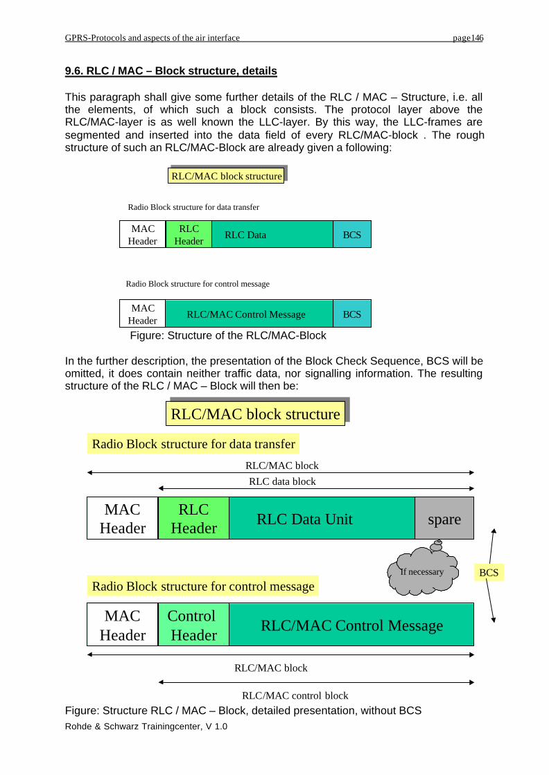
9.6. RLC / MAC – Block structure, details
This paragraph shall give some further details of the RLC / MAC – Structure, i.e. allthe elements, of which such a block consists. The protocol layer above theRLC/MAC-layer is as well known the LLC-layer. By this way, the LLC-frames aresegmented and inserted into the data field of every RLC/MAC-block . The roughstructure of such an RLC/MAC-Block are already given a following:
Figure: Structure of the RLC/MAC-Block
In the further description, the presentation of the Block Check Sequence, BCS will beomitted, it does contain neither traffic data, nor signalling information. The resultingstructure of the RLC / MAC – Block will then be:
Figure: Structure RLC / MAC – Block, detailed presentation, without BCS
RLC DataMACHeader
RLCHeader BCS
RLC/MAC block structureRLC/MAC block structure
Radio Block structure for data transfer
RLC/MAC Control MessageMACHeader BCS
Radio Block structure for control message
RLC Data UnitMAC
HeaderRLC
Header spare
RLC/MAC block structureRLC/MAC block structure
Radio Block structure for data transfer
RLC/MAC Control MessageMAC
Header
Radio Block structure for control messageIf necessary BCS
RLC/MAC blockRLC data block
RLC/MAC block
RLC/MAC control block
Control Header

GPRS-Protocols and aspects of the air interface page147
Rohde & Schwarz Trainingcenter, V 1.0
As to be seen, there are 2 different structures to be taken into consideration, oneused to transport data of higher layer protocols, the other used for transportation ofsignalling information between two RLC peer entities. Furthermore there must to bedistinguished between Uplink and Downlink. The following figure describes thesucceeding different points of consideration. The structure of the following chapter isgiven belong this picture, it describes the different RLC/MAC-blocks.
Figure: Different structures of RLC/MAC-Blocks
The content of the spare-bits is always the value 0, their tasks are in case of anoverhang of the data field to fill up the content bit sequence up to the replenishmentof the burst. They are only used in that way and they do not have other functions.
it9.7. GPRS RLC-Data Blocks, Data transfer.
The RLC Data Block consists of an RLC-Header, a data field, the RLC Data Unit andspare bits if necessary. The length of the RLC Data Blocks depends of the usedCoding Scheme.The following table, taken out of the GSM-Specifications shows the lengths of thedata field plus RLC-Header field in octets, corresponding to the used coding field.
Channel CodingScheme
RLC data blocksize Number of
spare bitsCS-1 22 0CS-2 32 7CS-3 38 3CS-4 52 7
Figure: Length of the RLC-Data Block, depending on the used Coding Scheme
Differences in Block Structre
RLC/MAC - Block
Data Transfer Signalling
Downlink Uplink Downlink Uplink
•MAC-Header•RLC-Data Block
•MAC-Header•RLC-DataBlock
•MAC-Header•RLC/MAC-Control Block
•MAC-Header•RLC/MAC Control Block

GPRS-Protocols and aspects of the air interface page148
Rohde & Schwarz Trainingcenter, V 1.0
Figure: Length of the RLC-Blocks
In t he following consideration of the RLC-Data Blocks there must be distinguishedbetween Downlink and Uplink. The structure is different in both cases.
RLC Data UnitRLC
Header spare
RLC block sizeRLC block size
RLC- Block structure for data transfer
RLC data block
Channel Coding Scheme
RLC data block size
without spare bits (octets)
Number ofspare bits
RLC datablock size(octets)
CS-1 22 0 22CS-2 32 7 32 7/8CS-3 38 3 38 3/8CS-4 52 7 52 7/8
Size =
RLC-Data Blockstructure
Uplink -direction
Downlink-direction

GPRS-Protocols and aspects of the air interface page149
Rohde & Schwarz Trainingcenter, V 1.0
9.7.1. RLC/MAC-Data Block for data transfer in downlink:
First lets contemplate the RLC/MAC-Block like it is sent in downlink direction. It hasthe following structure:
Figure: RLC / MAC – Block structure for data transfer in downlink
Contemplating the single elements of the complete structure of this RLC/MAC-Block.Starting with the MAC- Header:
Payload Type RRBP USF
TFI
Time to Live Protocol Header Checksum
Length indicator
RLC Data
S/P
PR FBI
BSN E
EM
Length indicator EM
MAC Header
Bit12345678
Octet 1
Octet 2
Octet 3 (optional)
Octet M (optional)
Octet N

GPRS-Protocols and aspects of the air interface page150
Rohde & Schwarz Trainingcenter, V 1.0
MAC – Header for Data transfer in downlink:
Figure: MAC – Header structure for Downlink-data transfer
It signifies:
Uplink State Flag, USF:As mentioned, the USF labels the legitimate user of the next uplink RadioBlocks, i.e. the following 4 Normal Bursts that the MS is allowed to transmit inuplink direction. The USF field is sent in all downlink RLC/MAC blocks andindicates the owner or use of the next uplink Radio block on the same timeslot.The USF field is three bits in length and eight different USF values can beassigned, except on PCCCH, where the value '111' (USF=FREE) indicatesthat the corresponding uplink Radio block contains PRACH.
Supplementary / Polling Bit, S/P:The S/P bit is used to indicate whether the RRBP field is valid or not valid. 0 =not valid, 1 = valid.
Relative Reserved Block Period, RRBP:The RRBP value specifies a single uplink block in which the mobile stationshall transmit either a PACKET CONTROL ACKNOWLEDGEMENT messageor a PACCH block to the network. The two bits are indicating a time interval,after that, the MS must send the control block. This procedure is valid in thecase if the RLC-block contains data as well as if it contains signallinginformation.
Payload Type:The Payload Type field shall indicate the type of data contained in remainderof the RLC/MAC block. Again, the expression signalling in this chapter meanssignalling of the RLC-layer and not signalling of higher protocol layers. Thisfield is essential, because of the packet oriented data transfer in GPRS thereare no fixed logical channels assigned to be used for signalling. The signallingis inserted into the data flow and has to be indicated separately.
Payload Type RRBP USFS/P MAC Header
Bit12345678

GPRS-Protocols and aspects of the air interface page151
Rohde & Schwarz Trainingcenter, V 1.0
RLC-Data Block for data transfer in downlink:
Explaining now the structure of the RLC-Block, as it is used for data transfer indownlink. Principally this block consists of a header, a data field and if necessarysome spare-bits.
Figure: RLC-Block structure for data transport in downlink
Final Block Indicator, FBI (1 Bit):The Final block indicator (FBI) bit indicates that the downlink RLC data block isthe last RLC data block of the downlink TBF.
0 = Current block is not last RLC data block in TBF1 = Current block is last RLC data block in TBF
Temporary Flow Identifier, TFI (5 Bit) :In RLC data blocks, the TFI identifies the Temporary Block Flow (TBF) towhich the RLC data block belongs. For the downlink and the uplink TFI the TFIfield is 5 bits in length and are encoded as a binary number with range 0 to 31.In downlink RLC/MAC control blocks, the TFI identifies the Temporary BlockFlow (TBF) to which the RLC/MAC control message contained in the downlinkRLC/MAC control block relates. If present, this field indicates the mobilestation to which the control message is addressed, and all other mobilestations shall ignore the control message. If this field is not present all mobilestations shall interpret the contents of the control message.
Power Reduction, PR (2 Bit).This field indicates how many dB the output power level of the actual RLC-Block is reduced compared with the BCCH-carrier frequency channel. Remark:At the moment, the feature Base Station Power Control in GPRS networks isin experimental phase and not realised. For that reason, this field does nothave a signification at the moment.
Block Sequence Number, BSN (7 Bit):The Block Sequence Number (BSN) field carries the sequence absolute BlockSequence Number (BSN') modulo Sequence Number Space (SNS) (128 in GPRSand 2048 in EGPRS) of each RLC data block within the TBF.
TFI
Time to Live Protocol Header Checksum
Length indicator
RLC Data
PR FBI
BSN E
EM
Length indicator EM
Octet 1
Octet 2
Octet 3 (optional)
Octet M (optional)
Octet N

GPRS-Protocols and aspects of the air interface page152
Rohde & Schwarz Trainingcenter, V 1.0
Extension Bit, E (1 Bit):The Extension (E) bit is used to indicate the presence of an optional octet inthe RLC data block header 0 = additional octet follows immediately, 1 = noadditional octet follows.
Length Indicator, LI (6 Bit per Octet, usage is optional):The Length Indicator is used to delimit LLC PDUs within the RLC data block.The first Length Indicator shall indicate the number of octets of the RLC datafield belonging to the first LLC PDU, the second Length Indicator shall indicatethe number of octets of the RLC data field belonging to the second LLC PDU,etc. Only the last segment of any LLC PDU of a TBF (either this segmentcarries the entire LLC PDU or not) shall be identified with a Length Indicatorwithin the corresponding RLC data block.
More Bit, M (1 Bit):In GPRS TBF mode, the M bit, along with the E bit and the Length Indicator(LI), are used to delimit LLC PDUs within a TBF. When the M bit is present itindicates whether or not another LLC PDU follows the current one within theRLC data block.
RLC Data (variable, depends on used Coding Scheme):The RLC data field contains the bits sequences of the higher protocol layers.Its length is variable and also depending from the used coding scheme. Thelength varies between 19, 29, 35 or 49 Octets.

GPRS-Protocols and aspects of the air interface page153
Rohde & Schwarz Trainingcenter, V 1.0
9.7.2. RLC/MAC – Block for data transfer in Uplink
The Structure of a RLC/MAC-Block for data transfer in uplink is given belong thefollowing figure:
Figure: RLC/MAC – Block for data transfer in Uplink
Also here we have to distinguish in our consideration between MAC-Header and theRLC-Data block.
Payload Type Countdown Value SI
TFI
Time to Live Protocol Header Checksum
Length indicator
Spare FBI
BSN E
EM
Length indicator EM
MAC Header
Bit12345678
Octet 1
Octet 2
Octet 3 (optional)
Octet M (optional)
Octet N
R
PI
TLLI
PFI
RLC Data

GPRS-Protocols and aspects of the air interface page154
Rohde & Schwarz Trainingcenter, V 1.0
MAC – Header for Data transfer in Uplink:
The MAC-Header for data transfer in Uplink has the following structure:
Figure: MAC-Header for Data transfer in Uplink
The single field are corresponding to:
Retry – Bit, R (1 Bit):The Retry (R) bit shall indicate whether the mobile station transmitted theCHANNEL REQUEST message, PACKET CHANNEL REQUEST message, orEGPRS PACKET CHANNEL REQUEST message one time or more than onetime during its most recent channel access. The mobile station shall send thesame value for the R bit in each uplink RLC/MAC block of the TBF. O = MShas sent channel request – only 1 time, 1 = channel request – message sentmore than 1 time.
Stall Indicator, SI (2 Bit):The Stall indicator (SI) bit indicates whether the mobile's RLC transmit windowcan advance (i.e., is not stalled) or can not advance (i.e., is stalled). Themobile station shall set the SI bit in all uplink RLC data blocks. 0 = MS transmitwindow is not stalled, 1 = MS transmit window is stalled
Countdown Value, CV (4 Bits):The Countdown Value (CV) field is sent by the mobile station to allow thenetwork to calculate the number of RLC data blocks remaining for the currentuplink TBF. It enables the network to estimate the number of radio blocks stillto be sent. The CV field is 4 bits in length and is encoded as a binary numberwith range 0 to 15. This forms more or less a counter that’s value is decrementfrom 15 up to 0 to countdown the last Radio Blocks.
Payload Type:This field indicates if the following RLC-Block contains signalling data or trafficdata. Does this field contain the value 0 0 , so it is implicated, that the contentof the RLC-block field is given as traffic data.
Payload Type Countdown Value SI MAC Header
Bit12345678
R

GPRS-Protocols and aspects of the air interface page155
Rohde & Schwarz Trainingcenter, V 1.0
RLC-Data Block for Data Transfer in Uplink:
The RLC-Data Block for Data transfer in Uplink consists, same as its counterpart forthe downlink direction of a header field, a data field and some eventually spare-bits.
Figure: RLC – Data Block for Data transfer in Uplink:
The single fields signify:
TLLI Indicator Bit, TI ( 1 Bit):Indicates, that there is an optional TLLI-field within the RLC-data block
Temporary Flow Identifier, TFI:In RLC data blocks, the TFI identifies the Temporary Block Flow (TBF) towhich the RLC data block belongs.
PFI Indicator Bit, PI (1 Bit):Index for the existence of an optional PFI – field.
Block Sequence Number, BSN (7 Bit):The Block Sequence Number BSN carries the reference number to indicatethe position of the actual RLC-block within the total TBF.
TFI
Time to Live Protocol Header Checksum
Length indicator
Spare TI
BSN E
EM
Length indicator EM
Octet 1
Octet 2
Octet 3 (optional)
Octet M (optional)
Octet N
PI
TLLI
PFI
RLC Data
123245678Bit

GPRS-Protocols and aspects of the air interface page156
Rohde & Schwarz Trainingcenter, V 1.0
Extension Bit, E (1 Bit):Indicator if an extension octet follows to the header.
Length Indicator, LI and M-Bit:Same function as in downlink, i.e. indicate that in the presented RLC areeventually more LLC PDU’s and are giving the length to reference them.
Temporary Logical Link Identifier, TLLI ( 4 Octets, optional):The optional TLLI field contains a TLLI encoded as the contents of the TLLIinformation element. TLLI is the identifier for the logical link between theSGSN and the MS. The TLLI is only transmitted within the first 3 Radio Blocksonly in uplink to guarantee, that the legitimated user uses the uplink resource.
Packet Flow Identifier, PFI.The PFI field contains a PFI value encoded as the contents of the PFIinformation element as defined in 3G TS 24.008, the UMTS – Specifications.The Packet Flow Identifier allows additional parameter to determine the dataflow context, e.g. the priority level.
Data field, RLC-Data:Same as in downlink, this field contains the data of higher protocol layers. Itslength is variable and depends on the used coding scheme.

GPRS-Protocols and aspects of the air interface page157
Rohde & Schwarz Trainingcenter, V 1.0
9.8. RLC/MAC-Block for Signalling
The RLC/MAC-Block is also used to convey signalling information, but again, herebyit is only meant the signalling between two RLC-entities. Signalling messages ofhigher protocol layers are regarded by the RLC/MAC-layer as traffic data, there is nofurther distinction. A RLC/MAC-Block used for transport of signalling information hasthe following general structure:
Figure: RLC/MAC-Block structure for signalling
The RLC/MAC-Block for signalling consists of a MAC-Header, an optional RLC-Control-Header and a field, that contains the RLC/MAC-signalling informationmessage.For the case of signalling transfer, it is always used the coding scheme 1, i.e. there isautomatically chosen the best error protection level.Also in this case, it has to be distinguished between uplink and downlink.
RLC/MAC Control MessageMAC
Header
Radio Block structure for control message
RLC/MAC block
RLC/MAC control block
Control Header

GPRS-Protocols and aspects of the air interface page158
Rohde & Schwarz Trainingcenter, V 1.0
9.8.1. RLC/MAC-Block for Signalling in Downlink
The RLC/MAC-Block naturally used for the convey of signalling messages, but onlysignalling messages of the RLC/MAC-layer possesses the following detailedstructure:
Figure: RLC/MAC-Block for Signalling in Downlink
MAC-Header for Signalling in Downlink
Again it has to be distinguished between MAC-Header and RLC-Data-Block. TheMAC-Header has the main task to indicate the following RLC-data block as carrier ofsignalling messages. The structure of only the MAC-Header looks like:
The single fields are corresponding to:
Uplink State Flag, USF (3 Bit):Is used to indicate the legitimated user or owner of the following Radio Block.The USF is contained in every downlink Radio Block, independent if thiscarries traffic data or signalling messages.
MAC Header
Bit12345678
Octet M
Octet 1 (optional)
Octet 22
Payload Type RRBP USF
RTI
Header Checksum
Control Message Contents
S/P
RBSN AC
TFI D
FS
PR Octet 2 (optional)
MAC Header
Bit12345678
Payload Type RRBP USFS/P

GPRS-Protocols and aspects of the air interface page159
Rohde & Schwarz Trainingcenter, V 1.0
Supplementary / Polling Bit, S/P (1 Bit):The S/P bit is used to indicate whether the RRBP field is valid or not valid. Bythat way, the MS can be “polled”, i.e. the MS is invited to send a controlmessage within a PACCH-Block.
Relative Reserved Block Period, RRBP (2 Bit):Same procedure as in the case of data transfer. There is given a time offsetvalue, relative to the actual frame number, after that the MS is requested tosend an control block on the PACCH.
Payload Type (2 Bit):This field distinguishes the content of the RLC-data field as followed:
0 1 RLC/MAC block contains an RLC/MAC control block that doesnot include the optional octets of the RLC/MAC control header
1 0 In the downlink direction, the RLC/MAC block contains anRLC/MAC control block that includes the optional first octet of theRLC/MAC control header. In the uplink direction, this value isreserved.
The value 11 is used for future developments.
RLC-Data Block for Signalling in Downlink
Hereby there are existing two possibilities how the structure or the block can looklike. One possibility is, that the RLC-Data Block contains fully a whole RLC/MAC-Signalling message, the other possibility is that the RLC-Data-Block contains anadditional Header-Field that gives further information. Which one of both possibilitiesis used, depends on the signalling message that is transmitted.The general structure is given as followed:
Figure: RLC-Data Block for Signalling in Downlink, including the optional RLC-Header field
Bit12345678
Octet M
Octet 1 (optional)
Octet 22
RTI
Header Checksum
Control Message Contents
RBSN AC
TFI D
FS
PR Octet 2 (optional)

GPRS-Protocols and aspects of the air interface page160
Rohde & Schwarz Trainingcenter, V 1.0
The single fields of this block contain the following information:
Reduced Block Sequence Number Bit, RBSN (1 Bit):The Reduced Block Sequence Number (RBSN) bit carries the sequencenumber of the downlink RLC/MAC control blocks. The RBSN bit is encoded asa binary number with range 0 to 1.
Radio Transaction Identifier, RTI (5 Bit):The Radio Transaction Identifier (RTI) field is used to group the downlinkRLC/MAC control blocks that make up an RLC/MAC control message andidentifies the segmented control message sequence with which the downlinkRLC/MAC control block is associated. The RTI field is five bits in length withrange 0 to 31.
Final Segment Bit, FS (1 Bit):The Final Segment (FS) bit indicates that the downlink RLC/MAC control blockcontains the final segment of an RLC/MAC control message. 0 = Current blockdoes not contain the final segment of an RLC/MAC control message, 1 =Current block contains the final segment of an RLC/MAC control message
Access Control Bit, AC (1 Bit):The Address Control (AC) bit is used to indicate the presence of the optionalTFI/D octet in the header of downlink RLC/MAC control blocks. 0 = additionaloctet with TFI/D-field, 1 = immediately following octet contains to the headerand carries the TFI/D-field.
Power Reduction Field, PR (2 Bit):The Power Reduction (PR) field indicates the power level reduction of thecurrent RLC block. This touches only the downlink messages and refers to thefeature that the BTS reduces its transmitting power on all channels except theBCCH carrier. Certainly, this feature will not be used in the first realisationstep.
Temporary Flow Identity, TFI (5 Bit):Just like in the case of data transfer, this field identifies the Temporary BlockFlow, TBF. In Downlink-Signalling messages, due to this field, the user orreceiver of the message can be addressed.
Direction Bit, D (1 Bit):The Direction (D) bit indicates the direction of the TBF identified by the TFIfield in the downlink RLC/MAC control block header. 0 = TBF in Downlink, 1 =TBF in Uplink.
Control Message Content:The rest of this field contains the original signalling message that is exchangedbetween the two RLC/MAC-entities. Its length is fixed and is given always as22 Octets. This is derived from the fact, that for signalling messages transfer,always Coding Schemes CS-1 are used, synonymous with maximum security.

GPRS-Protocols and aspects of the air interface page161
Rohde & Schwarz Trainingcenter, V 1.0
9.8.2. RLC/MAC-Block for Signalling in Uplink
As last case we want to consider the case of transfer of signalling messages in uplinkdirection. In that case, we found the block structure given as followed:
Figure: RLC/MAC-Block for Signalling in Uplink
In the case of uplink, the only important and relevant field is the MAC-header thatdistinguishes between signalling messages and data transfer.
MAC-Header for Signalling in Uplink:
Figure: MAC-Header for Signalling in Uplink
On the first view it can be seen, that the MAC-Header has a completely reducedformat. In effective, there are only two relevant fields:
Payload Type (2 Bit):Identifies the content of the RLC-Block as signalling. In uplink it can bedistinguished between the following parameters:
0 0 RLC/MAC Block contains RLC-data block0 1 RLC/MAC Block contains RLC/MAC Control Block, i.e. signalling
message for the RLC-layer.
Retry Bit, R (1 Bit):Just as in the case of data transfer, this bit indicates whether the ChannelRequest message on the PRACH or RACH at the beginning of the TBFestablishment was sent one time or more.
MAC Header
Bit
12345678
Octet 1
Octet 22
Payload Type spare
Control Message Contents
R
MAC Header
Bit12345678
Payload Type spare R

GPRS-Protocols and aspects of the air interface page162
Rohde & Schwarz Trainingcenter, V 1.0
Spare (5 Bit):Filling bits, those are set on 0, without further signification.
RLC-Data Block for Signalling in Uplink:
In Uplink direction there is no RLC-header for signalling. There is only a data fieldthat contains exclusively signalling information. The length of this field is fixed and isabout 22 octets. Channel coding is performed belonging to Coding Scheme 1.
9.9. RLC-Signalling messages
Via the RLC/MAC-Layer the Radio Resource Management is sending a lot ofsignalling messages. The following figures are presenting the allowed signallingmessages exchanged between MS and network. It shall again be reminded, thatthese messages are only those of the RLC-layer, referring to the air interface, orradio resource management. Further signalling messages are part of higher layerprotocols, for example messages of the GPRS Mobility Management, GMM orSession Management. These messages are transported via the LLC-layer and areregarded as traffic data by the RLC/MAC-layer.
Figure: Messages of the Radio Resource Management transferred via the RLC/MAClayer in downlink-direction
GRR Signalling Messages(Via RLC/MAC)
Downlink Messages
• Packet Access Reject• Packet Cell Change Order• Packet Downlink Assignment• Packet Paging Request• Packet PDCH Release• Packet Polling Request• Packet Power Control/Timing Advance• Packet PRACH Parameters• Packet Queueing Notification• Packet Timeslot Reconfigure
•Packet TBF Release•Packet Uplink Ack/Nack•Packet Uplink Assignment•Packet Downlink Dummy Control Block•Packet System Information Type 1•Packet System Information Type 2•Packet System Information Type 3•Packet System Information Type 3 bis•Packet System Information Type 4•Packet System Information Type 5•Packet System Information Type 13

GPRS-Protocols and aspects of the air interface page163
Rohde & Schwarz Trainingcenter, V 1.0
Figure: Messages of the Radio Resource Management sent via the RLC/MAC inuplink-direction
9.10. Access to the radio interface: 1 Phase Access and 2 Phase Access
Previous chapters are describing the procedure, how a data transfer is initiated viathe MM-context activation procedure and the PDP context activation procedure. Butthese processes are performed by higher layer protocols. The following paragraphshall describe the physical channel activation procedure or the request for physicalresource. It is explained, how data is transferred via the radio link, with the help of thetransport structure: Radio Block. But it is actually not described how the allocation ofuplink or downlink physical resource is been performed.
Mobile Originated Packet TransferPrerequisite for any kind of data transfer is the previous MM and PDP contextactivation. These are messages of higher protocol layers and they have to beembedded in lower layer messages, e.g. the Channel Request message in the RLClayer shall indicate this higher layer request. The data to be transferred can be abursty application, there is no continuous data transfer, and it is running in burstyintervals. Before the continuation of the physical data transfer there must be anrenewed physical resource activation procedure.
How is the request for physical channel resource performed in GPRS and how is theallocation of physical resource realised?
In GPRS it must be distinguished between one phase and two phase access. Theone phase access is mandatory, while the two phase access is optional for thenetwork. The MS has to perform both kind of access routines, depending what thenetwork requires.
GRR Signalling Messages (Via RLC/MAC)
• Uplink Messages• Packet Cell Change Failure• Packet Control Acknowledgement• Packet Downlink Ack/Nack• Packet Uplink Dummy Control Block• Packet Measurement Report• Packet Resource Request• Packet Mobile TBF Status (SMG #30+)• Packet PSI Status (SMG #30+)

GPRS-Protocols and aspects of the air interface page164
Rohde & Schwarz Trainingcenter, V 1.0
The following figure describes the two phases in radio network access:
Mobile Originated Packet Transfer
Packet Channel Request1
2 Packet Immediate Assignment
Packet Resource Request3
4 Packet Resource Assignment
PAGCH or AGCH
PRACH or RACH
PACCH
PACCH
Phase One Access
Phase Two Access
(optional)
Mobile Originated Packet Transfer
MS Net-work
Packet Channel Request1
2 Packet Immediate Assignment
Packet Resource Request3
4 Packet Resource Assignment
PAGCH or AGCH
PRACH or RACH
PACCH
PACCH
Phase OneAccess
Phase Two Access(optional)
Figure: Radio network access in one phase or two phases
1. Packet Channel RequestThe Uplink Packet Transfer is initiated by a Packet Channel Request message,sent from the MS. This message can either be send on a RACH or PRACH. TheMS has two possibilities to indicate or request a physical resource. Onepossibility is the request for an uplink radio block, i.e. the physical resourceneeded is only one radio block. This is used in the case of higher layer signallingmessages, for example the GPRS Attach request message is indicated in thatway. Or the MS has the possibility to initiate the two phase access in that way,the first Packet Channel Request Message requests only one radio block, butthe message sent in this allocated radio block will then be a Packet ResourceRequest message to request more radio resource.The second possibility is the request for a PDCH, the network gets theinformation that the MS requests for a PDCH. But the result of this message willbe the allocation of a single PDCH, i.e. physical resource on one timeslot.
2. Packet Immediate AssignmentThe network assigns physical channel resource with the aid of the PacketImmediate Assignment message. The assignment of physical resource shallconsider the needed channel capacity. But this seems to be the problem, GPRSallows a lot of different data transfer combination, for example in the chapter

GPRS-Protocols and aspects of the air interface page165
Rohde & Schwarz Trainingcenter, V 1.0
about GPRS Services there were given a lot of Quality of Service Profiles.Compared to GSM, where the request was only Full Rate Traffic Channel or onlysignalling message on SDCCH, GPRS allows much more. But the MS need morecapacity in the request message to describe more detailed the needed physicalresource. But this capacity is not available in Packet Channel Request messagesent within an Access Burst. The network has, after the reception of such anAccess Burst only few information about the requested service and therefore howmuch physical channel resource shall be assigned.• The network assigns one single PDCH, i.e. one timeslot on one frequency
channel. If the MS would request more, it will answer with the additionalPacket Resource Request message on the assigned PDCH.
• Another possibility is, that the network assigns only physical resource aboutone uplink radio block. This is done in that way, if the MS has onlyrequested one uplink radio block, practically done to transmit signallingmessages, e.g. GPRS Attach. But the network to request the two-phaseaccess can also use this procedure. If the MS has requested a PDCH, thenetwork will assign only a single uplink radio block, knowing that this ismuch less then needed to force the MS to react with the transmission of aPacket Resource Request message and handing out further informationabout the required service.
Power Control (PC) and Timing Advance (TA) information is included in thePacket Uplink Assignment message.
The one phase network access is restricted to the two messages Packet ChannelRequest and Packet Immediate Assignment.
The two-phase access is always initiated if the MS is not content with the assignedphysical resource, it requests much more. Its use is optional, depending on therequested service.
3. Packet Resource RequestThis message includes a detailed description of the requested service and of therequested physical channel resource.
4. Packet Resource AssignmentThis message is the answer of the network to the requested resource andcontains a channel description element, indicating what physical channelresource is assigned on the uplink direction. Power Control (PC) and TimingAdvance (TA) information are included into this message.The MS has after receipt of this message no further possibility to request morephysical resource, it may only terminate the connection if the assigned resourcedoes not fit with the desired service.
Both messages, Packet Resource Request and Packet Resource Assignment aretransmitted on the PACCH.