Embed Size (px)
Citation preview
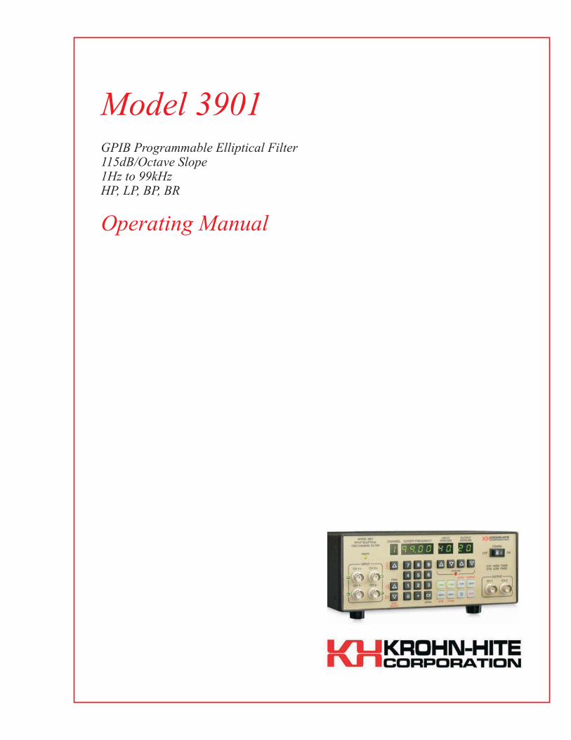
Model 3901GPIB Programmable Elliptical Filter115dB/Octave Slope1Hz to 99kHzHP, LP, BP, BR
Operating Manual

Service and WarrantyKrohn-Hite Instruments are designed and manufactured in accordance withsound engineering practices and should give long trouble-free service undernormal operating conditions. If your instrument fails to provide satisfactoryservice and you are unable to locate the source of trouble, contact our ServiceDepartment at (508) 580-1660, giving all the information availableconcerning the failure.
DO NOT return the instrument without our written or verbal authorization todo so. After contacting us, we will issue a Return Authorization Number whichshould be referenced on the packing slip and purchase order. In most cases, wewill be able to supply you with the information necessary to repair the instru-ment, avoiding any transportation problems and costs. When it becomes nec-essary to return the instrument to the factory, kindly pack it carefully and shipit to us prepaid.
All Krohn-Hite products are warranted against defective materials and work-manship. This warranty applies for a period of one year from the date of deliv-ery to the Original Purchaser. Any instrument that is found within the one yearwarranty period not to meet these standards, will be repaired or replaced. Thiswarranty does not apply to electron tubes, fuses or batteries. No other war-ranty is expressed or implied.
Krohn-Hite Corporation reserves the right to make design changes at any timewithout incurring any obligation to incorporate these changes in instrumentspreviously purchased.
Modifications to this instrument must not be made without the written consentof an authorized employee of Krohn-Hite Corporation.
Model 3901
1Hz to 99kHzLow-Pass, High-Pass
Band-Pass, Band-RejectGPIB Programmable Elliptical Filter
Serial No. _____________________
Operating Manual
15 Jonathan Drive, Unit 4, Brockton, MA 02301-5566 U.S.A.Tel: (508) 580-1660; Fax: (508) 583-8989www.krohn-hite.com; [email protected]
Copyright 2005 Krohn-Hite CorporationAll rights reserved. Contents of this publication may not be reproduced in
any form without the written permission of Krohn-Hite Corporation.Printed in U.S.A.
Ver. 05.16.05

Notes
Table of Contents1.0 Section 1
1.1 Introduction · · · · · · · · · · · · · · · · · · · · · · · · · · · · · · · · · · · · · 1-11.2 Specifications · · · · · · · · · · · · · · · · · · · · · · · · · · · · · · · · · · · · 1-1
1.2.1 Function . . . . . . . . . . . . . . . . . . . . . . . . . . . . . . . . . . 1-11.2.2 Fil ter Mode . . . . . . . . . . . . . . . . . . . . . . . . . . . . . . . . 1-11.2.3 Amplifier Mode (Each Channel) . . . . . . . . . . . . . . . . . . . 1-21.2.4 General . . . . . . . . . . . . . . . . . . . . . . . . . . . . . . . . . . . 1-31.2.5 Options . . . . . . . . . . . . . . . . . . . . . . . . . . . . . . . . . . . 1-3
1.3 Shipping to Krohn-Hite for Repair or Calibration · · · · · · · · · · · · · 1-31.4 Claim for Damage in Shipment to Original Purchaser · · · · · · · · · · · 1-41.5 External Cleaning· · · · · · · · · · · · · · · · · · · · · · · · · · · · · · · · · · 1-4
2.0 Section 22.1 Introduction · · · · · · · · · · · · · · · · · · · · · · · · · · · · · · · · · · · · · 2-12.2 Turn-On Procedure · · · · · · · · · · · · · · · · · · · · · · · · · · · · · · · · · 2-12.3 Self-Test · · · · · · · · · · · · · · · · · · · · · · · · · · · · · · · · · · · · · · · 2-12.4 Front Panel Controls and Display· · · · · · · · · · · · · · · · · · · · · · · · 2-2
2.4.1 Data Keys and Display . . . . . . . . . . . . . . . . . . . . . . . . . 2-22.4.2 Parameter and Control Keys . . . . . . . . . . . . . . . . . . . . . 2-22.4.3 Channel Selection . . . . . . . . . . . . . . . . . . . . . . . . . . . . 2-42.4.4 Cutoff Frequency . . . . . . . . . . . . . . . . . . . . . . . . . . . . 2-42.4.5 Input Gain (Pre-Fil ter) . . . . . . . . . . . . . . . . . . . . . . . . . 2-42.4.6 Output Gain (Post-Fil ter) . . . . . . . . . . . . . . . . . . . . . . . 2-42.4.7 Digit Select/ Increment and Decrement . . . . . . . . . . . . . . 2-42.4.8 Key Click Feature On/Off . . . . . . . . . . . . . . . . . . . . . . . 2-4
2.5 Rear Panel Controls · · · · · · · · · · · · · · · · · · · · · · · · · · · · · · · · 2-52.5.1 Introduction . . . . . . . . . . . . . . . . . . . . . . . . . . . . . . . . 2-52.5.2 BNC Connectors and Indicators . . . . . . . . . . . . . . . . . . . 2-5
2.5.2.1 Input Connectors · · · · · · · · · · · · · · · · · · · · · · · · · · · · · 2-5
2.5.2.2 Output Connectors · · · · · · · · · · · · · · · · · · · · · · · · · · · · 2-5
2.5.2.3 Indicators · · · · · · · · · · · · · · · · · · · · · · · · · · · · · · · · · 2-5
2.5.3 DC Level Adj (Rear Panel) . . . . . . . . . . . . . . . . . . . . . . 2-52.5.4 Power . . . . . . . . . . . . . . . . . . . . . . . . . . . . . . . . . . . . 2-52.5.5 GPIB Connector . . . . . . . . . . . . . . . . . . . . . . . . . . . . . 2-5
Table of Contents
i-i
2.6 Fil ter Operating Characterist ics · · · · · · · · · · · · · · · · · · · · · · · · · 2-62.6.1 Introduction . . . . . . . . . . . . . . . . . . . . . . . . . . . . . . . . 2-62.6.2 Amplitude Response . . . . . . . . . . . . . . . . . . . . . . . . . . 2-62.6.3 Low-Pass Phase Response . . . . . . . . . . . . . . . . . . . . . . . 2-62.6.4 High-Pass Phase Response . . . . . . . . . . . . . . . . . . . . . . 2-72.6.5 Group Delay . . . . . . . . . . . . . . . . . . . . . . . . . . . . . . . 2-82.6.6 Transient Response . . . . . . . . . . . . . . . . . . . . . . . . . . . 2-82.6.7 Impulse Response . . . . . . . . . . . . . . . . . . . . . . . . . . . . 2-92.6.8 Variable Band-Pass Operation . . . . . . . . . . . . . . . . . . . . 2-92.6.9 Band-Reject Operation . . . . . . . . . . . . . . . . . . . . . . . . 2-10
3.0 Section 33.1 Introduction · · · · · · · · · · · · · · · · · · · · · · · · · · · · · · · · · · · · · 3-13.2 Preliminary Programming Information · · · · · · · · · · · · · · · · · · · · 3-1
3.2.1 GPIB Primary Bus Address . . . . . . . . . . . . . . . . . . . . . . 3-13.2.2 GPIB Bus Interface Programming Connector . . . . . . . . . . . 3-2
3.3 ASCII Data Commands · · · · · · · · · · · · · · · · · · · · · · · · · · · · · · 3-33.3.1 Format . . . . . . . . . . . . . . . . . . . . . . . . . . . . . . . . . . . 3-33.3.2 Types of Data Commands . . . . . . . . . . . . . . . . . . . . . . . 3-33.3.3 Table of ASCII Commands . . . . . . . . . . . . . . . . . . . . . . 3-33.3.4 Examples . . . . . . . . . . . . . . . . . . . . . . . . . . . . . . . . . 3-5
3.3.4.1 Example 1 · · · · · · · · · · · · · · · · · · · · · · · · · · · · · · · · 3-5
3.3.4.2 Example 2 · · · · · · · · · · · · · · · · · · · · · · · · · · · · · · · · 3-5
3.3.4.3 Example 3 · · · · · · · · · · · · · · · · · · · · · · · · · · · · · · · · 3-5
3.4 IEEE-488 Standard Commands · · · · · · · · · · · · · · · · · · · · · · · · · 3-63.4.1 Multi-Line Messages . . . . . . . . . . . . . . . . . . . . . . . . . . 3-63.4.2 Poll ing Commands . . . . . . . . . . . . . . . . . . . . . . . . . . . 3-7
3.4.2.1 Parallel Polling · · · · · · · · · · · · · · · · · · · · · · · · · · · · · · 3-7
3.4.2.2 Service Request And Serial Polling · · · · · · · · · · · · · · · · · · · · 3-8
3.4.2.3 Serial Responses · · · · · · · · · · · · · · · · · · · · · · · · · · · · · 3-8
3.4.3 Uniline Messages . . . . . . . . . . . . . . . . . . . . . . . . . . . . 3-93.5 Talker Format · · · · · · · · · · · · · · · · · · · · · · · · · · · · · · · · · · · · 3-9
3.5.1 Parameter Information Format . . . . . . . . . . . . . . . . . . . 3-103.5.2 Model Number and Software Version Format . . . . . . . . . . 3-10
3.6 Programming Examples · · · · · · · · · · · · · · · · · · · · · · · · · · · · · 3-103.6.1 Example 1 - Microsoft Quick Basic . . . . . . . . . . . . . . . . 3-103.6.2 Example 2 - Borland Turbo C . . . . . . . . . . . . . . . . . . . . 3-123.6.3 Example 3 - National Instruments IBIC . . . . . . . . . . . . . 3-18
Table of Contents
i-ii
4.0 Section 44.1 Introduction · · · · · · · · · · · · · · · · · · · · · · · · · · · · · · · · · · · · · 4-14.2 Required Test Equipment · · · · · · · · · · · · · · · · · · · · · · · · · · · · · 4-14.3 Channel 1 - High-Pass · · · · · · · · · · · · · · · · · · · · · · · · · · · · · · · 4-1
4.3.1 Pre-Fil ter. Post-Fil ter and Unity Gain Accuracy . . . . . . . . . 4-14.3.2 Low Bands Ripple Response . . . . . . . . . . . . . . . . . . . . . 4-24.3.3 High Band Ripple Response . . . . . . . . . . . . . . . . . . . . . 4-24.3.4 Stopband Attenuation . . . . . . . . . . . . . . . . . . . . . . . . . . 4-3
4.3.4.1 Band 1 · · · · · · · · · · · · · · · · · · · · · · · · · · · · · · · · · · 4-3
4.3.4.2 Band 2 · · · · · · · · · · · · · · · · · · · · · · · · · · · · · · · · · · 4-3
4.3.4.3 Band 3 · · · · · · · · · · · · · · · · · · · · · · · · · · · · · · · · · · 4-3
4.3.4.4 Band 4 · · · · · · · · · · · · · · · · · · · · · · · · · · · · · · · · · · 4-3
4.3.5 Cutoff Frequency Accuracy . . . . . . . . . . . . . . . . . . . . . . 4-34.3.6 Noise Measurements (2MHz Detector Bandwidth) . . . . . . . 4-4
4.4 Channel 2 - Low-Pass · · · · · · · · · · · · · · · · · · · · · · · · · · · · · · · 4-44.4.1 Pre-Fil ter, Post-Fil ter, and Unity Gain Accuracy . . . . . . . . 4-44.4.2 Low Band Ripple Response . . . . . . . . . . . . . . . . . . . . . . 4-54.4.3 High Band Ripple Response . . . . . . . . . . . . . . . . . . . . . 4-54.4.4 Stopband Attenuation . . . . . . . . . . . . . . . . . . . . . . . . . . 4-5
4.4.4.1 Band 1 · · · · · · · · · · · · · · · · · · · · · · · · · · · · · · · · · · 4-5
4.4.4.2 Band 2 · · · · · · · · · · · · · · · · · · · · · · · · · · · · · · · · · · 4-6
4.4.4.3 Band 4 · · · · · · · · · · · · · · · · · · · · · · · · · · · · · · · · · · 4-6
4.4.5 Cutoff Frequency Accuracy . . . . . . . . . . . . . . . . . . . . . . 4-64.4.6 Noise Measurements (2MHz Detector Bandwidth) . . . . . . . 4-64.4.7 Passband Gain and Distort ion Tests . . . . . . . . . . . . . . . . . 4-7
Table of Contents
i-iii
This page intentionally lef t blank.
Table of Contents
i-iv
Sect ion 1
General Description
1.1 Introduction
The Krohn-Hite Model 3901 programmable, two channel, high-pass/low-pass elliptical filter/volt-age gain amplifier is one of a family of programmable filters fromKrohn-Hite. As an elliptical filter,theModel 3901 has two independent filter channels, one low-pass and the other high-pass, allowingfor band-pass operationwith a tunable cutoff frequency range from1Hz to 99kHz and a role-off rateof 115dB/octave.Each filter section has aminimumstopband attenuation of >80dB and a passband ripple of typically0.22dB. The 3901 provides either a single-ended or differential input with a common mode rejec-tion of >60dB. Input gains up to 40dB in 10dB steps and output gains to 20dB in 10dB steps are alsoprovided. The 3901 will accept input signals of ±10V peak at 0dB gain and has selectable ac or dccoupling. The filter is GPIB bus programmable and is complimented with non-volatile memory forstorage of up to 99 front panel set-ups. Overload detectors are standard and assist the user in detect-ing excessive input signals or incorrect gain settings.The 3901q is also a programmable voltage gain amplifier for applications that require a low-noiseamplifier. The amplifier has a bandwidth of 1MHz and gains to 60dB, selectable in 10dB steps, anda wideband noise <100µV.Typical applications for the Model 3901 are: distortion measurements, separating specificbandwidths of information, enhancing signal-to-noise ratio, low noise pre-amplification and manymore.
1.2 Specifications
1.2.1 Function
Two independent filter channels. Channel 1, high-pass or amplified by-pass; Channel 2, low-pass oramplified by-pass; one channel of band-pass or band-reject with external connections.
1.2.2 Filter Mode
Type: 7-pole, 6-zero elliptical.
Attenuation: 115dB/octave.
Passband Ripple: 0.22dB typical, 0.4dB max.
Tunable Frequency Range fc: 1Hz to 99kHz
Frequency Control: Keypad entry or increment, decrement keys.
Section 1 - General Description
1-1
Bandwidth: High-Pass, fc to upper 3dB cutoff, >500kHz at 1Vrms with 0dB gain. Low-Pass, dccoupled, dc to fc; ac coupled, 0.32Hz to fc.
RelativeGain at fc:Low-Pass, –0.22dB at 1.01fc nominal;High-Pass, –0.22dB at 0.99fc nominal.
Cutoff Frequency Accuracy: ±2%.
FrequencyResolution: 1Hz, 1Hz to 99Hz; 10Hz, 100Hz to 990Hz; 100Hz, 1kHz to 9.9kHz; 1kHz,10kHz to 99kHz.
Stopband Attenuation: >80dB.
Stopband Frequency (fs): Low-Pass, 1.7fc; High-Pass, 0.59fc.
Insertion Loss: 0dB ±0.1dB.
Pre-Filter Gain: 0dB, 10dB, 20dB, 30dB, 40dB ±0.2dB.
Post-Filter Gain: 0dB, 10dB, 20dB ±0.2dB.
Input Coupling: ac or dc.
WidebandNoise (RFI):min. gain, 1kHz cutoff, <400µV, 99kHz cutoff, <1mV;Max. gain, <20µV.
Harmonic Distortion: –80dB at 1kHz.
Inter-ModulationDistortion: –80dBbelow full scale volts at 70kHz and 90kHz input frequency.
Spurious Components: –80dB below full scale with input source <50 ohms.
DC Stability: Typically ±10mV/°C.
Crosstalk Between Channels: –85dB below full scale with input source <50 ohms.
1.2.3 Amplifier Mode (Each Channel)
Bandwidth: dc coupled, dc to >1MHz min gain, >400kHz max. gain; ac coupled, 0.32Hz to>1MHz min gain, >400kHz max gain.
Insertion Loss: 0dB ±0.05dB.
Gain: 10dB to 60dB in 10dB steps ±0.1dB.
Input: Differential or single-ended +(in phase), –(inverted).
CMRR: >60dB to 10kHz; approximately 50dB at 100kHz.
Sensitivity: 10mV peak with 60dB total gain for 10V peak output.
Maximum Input: ±10V peak at 0dB gain reduced in proportion to gain setting.
Impedance: 1 megohm in parallel with 100pf.
Coupling: ac or dc.
Maximum DC Component: ±100V in ac coupled mode.
Output: Maximum Voltage (o.c.): 7Vrms to 200kHz; 3Vrms to 500kHz; 1Vrms to 1MHz.
Impedance: 50 ohms.
DC Offset: Adjustable to zero volts.
Harmonic Distortion (1V output): –80dB (0.01%) to 10kHz; –60dB (0.1%) to 100kHz..
Wideband Noise (referred to input, 2MHz BW detector): 100µV min. gain; 20µV max. gain.
Section 1 - General Description
1-2
DC Stability (RFI): Typically ±10mV/°C.
Crosstalk Between Channels: >85dB below full scale with input source <50 ohms.
1.2.4 General
Memory: 99 selectable groups; memory is non-volatile battery-backed CMOS.
Overload Modes: Three selectable modes; non-latching, that monitors all channels and displaysthe first channel to have an overload; latching, that maintains the overload display until it is cleared;and no indications.
Overload Indicators: LEDs for input and output. Gain display flashes when overload occurs ondisplayed channel.
Input Indicators: Green LEDs to indicate active input BNC.
Self-Test Diagnostics:MPU checks unit upon power-up. Display indicates failure mode.
Displays: 7 segment, green, LED; 0.3" high.
Remote Programming: IEEE-488.1 interface. Subsets: SH1, AH1, T6, L4, SR1, RL1, PP1, DC1,DT0, C0, E1.
Operating Temperature: 0ºC to 50ºC.
Isolation to Chassis: ±100Vdc.
Storage Temperature: –20°C to 70°C.
Input/Output Connectors: BNC, front and rear.
Power Requirements: 90-132/180-264 volts ac, 50Hz-400Hz, 40 watts.
Dimensions: 3.5" (9cm) high, 8.5" (21.8cm) wide, 18" (46.2cm) deep.
Weights: 12 lbs (5.4kg) net; 14 lbs (6.3kg) shipping.
Accessories: 6 foot, 3 terminal line cord; operating manual.
1.2.5 Options
Rack Mounting Kit: Part No. RK-37, permits installation of the Model 3901 into a standard 19"rack spacing.
Band-Reject Kit: Part No. BR-30, connectors and cables to adapt two channels for series(band-pass) or parallel (band-reject) operation.
Extended 1 Year Warranty: Part No. EW3901.
Specifications apply at 25°C ±5°C.Specifications subject to change without notice.
Section 1 - General Description
1-3
1.3 Shipping to Krohn-Hite for Repair or Calibration
All shipments of Krohn-Hite products should be made via United Parcel Service (UPS) or “BestWay” prepaid. The product should be shipped in its original shipping carton; or if not available, useany suitable container that is rigid and of adequate size. If a substitute container is used, the productshould be wrapped in 4 inches of excelsior or similar shock-absorbing material.
1.4 Claim for Damage in Shipment to Original Purchaser
The product should be thoroughly inspected immediately upon original delivery to purchaser. Allmaterial in the container should be checked against the enclosed packing list. Krohn-Hitewill not beresponsible for shortages against the packing list unless notified immediately. If the product is dam-aged in any way, a claim should be filed with the carrier immediately. (To obtain a quotation to re-pair the damage, contact Krohn-Hite at (508) 580-1660.) Final claim and negotiations with the car-rier must be completed by the customer.
1.5 External Cleaning
Note: To avoid electrical shock or instrument damage, never get water inside the case. To avoidinstrument damage, never apply solvents.Should the Model 3901 need cleaning, wipe the instrument with a cloth that is lightly dampenedwith water or a mild detergent solution.
Section 1 - General Description
1-4
Sect ion 2
Operation
2.1 Introduction
The Model 3901 is an elliptical filter with two independent channels, one low-pass and onehigh-pass, covering the frequency range from 1Hz to 99kHz. All filter parameters are programma-ble via front panel keyboard controls or remotely over the GPIB interface bus.The filter has twomodes of operation: filtermode and amplifiermode. Eachmodewill be explainedin detail in this section.
2.2 Turn-On Procedure
The Model 3901 line voltage range has been either preset for 115V or 230V operation. To changethis setting, remove the bottom cover to expose the line switch. Be sure to change the fuse to theproper rating for the line switch setting selected.Make certain the power switch on the front panel is set to off.Plug the line cord into the unit, then the ac outlet.If theModel 3901 is to be programmed remotely, connect the GPIB bus cable to the rear panel con-nector of the 3901.After reviewing the Self-Test feature below, turn on the Model 3901.
2.3 Self-Test
When theModel 3901 is turned on, themicroprocessor performs a self-test routine whereby the en-tire RAM and ROM operation is verified. During the test, the front panel LEDs and Displays willlight sequentially. If there is amalfunction on themicroprocessor board, such as a defectiveRAMorROM, the sequencewill stop and the word “bad”will appear in the display followed by a number 1,2 or 3. The table below give a description of each failure.
Table 2.1 Self-Test Part Failure
Display Indication Bad Internal Part“Bad 1” U210“Bad 2” U209“Bad 3” U208
Section 2 - Operation
2-1
When the self-test program is complete, theModel 3901will return to the last set-up prior to turningthe unit off. The 3901 is now ready to be programmed for operation.
2.4 Front Panel Controls and Display
2.4.1 Data Keys and Display
Data entry keyboard controls [0] to [9] and [.] set the numeric value of the parameter selected. To en-ter 1.5kHz, press the [1][.][5] keys and the parameter key [KILO] and [FREQ]. The cutoff fre-quency entered will be indicated in the display.
2.4.2 Parameter and Control Keys
[KILO] When pressed, multiplies the numeric value of thekeyboard entry by 103.
[MEGA] When pressed: multiplies the numeric value of thekeyboard entry by 106.
[FREQ] When pressed, enters and/or displays frequency inHertz.
[TYPE] When pressed, display indicates the filter type, “EL -7” (7-Pole Elliptical).
[MODE] When pressed, display indicates the mode of opera-tion for the channel displayed.
[RECLL]
When preceded by a number, it will recall the entireinstrument set-up from thememory location selected.
When first pressed, the display indicates the numberof the next memory location to be recalled. For exam-ple, the display will indicate the following: “n=09”.Pressing the [RECLL] key again will recall the entireinstrument set-up from the memory location “09”.
When pressed to indicate the nextmemory location tobe recalled only, pressing the [CE] (clear entry key)will restore the display to the cutoff frequency setting.
[ALL CH] Used on other models.[SHIFT] The [SHIFT] key in conjunction with other keys,
Section 2 - Operation
2-2
OverloadDetection
When [SHIFT][MODE] is first pressed, the display willindicate the overloadmode currently selected. Press-ing a number form [1] to [3] then [SHIFT][MODE] willselect the following overload conditions.
[1}[SHIFT][MODE]will select no overload indication.
[2][SHIFT][MODE] will select the non-latching mode.The 3901will monitor all channels and display the firstchannel to have an overload condition.
[3][SHIFT][MODE] will select the latching mode. Inthis mode, the 3901 will maintain the overload displayuntil it is cleared.
Store
When [SHIFT][RECLL] is first pressed, the display in-dicates the number of the next memory location avail-able. For example, the display will indicate the follow-ing: “n=09”. Pressing [RECLL] again will store the en-tire instrument set-up into that memory location. If an-other location is desired, enter that location on thekeyboard and then press [SHIFT][RECLL].
When [SHIFT][RECLL] is preceded by a number from[0] to [98], the 3901 will store the entire instrumentset-up into the memory location selected. The maxi-mum number of memory groups is 99.
When [SHIFT][RECLL] is pressed to indicate the nextmemory location only, the clear entry [CE] key restorethe display to the cutoff frequency setting.
AC/DCCoupling
Pressing the [SHIFT] key followed by the [TYPE] keywill display the input coupling, indicating “AC” or “dC”,and will alternate between the two.
GPIBAddress
When the [SHIFT] key followed by the [MEGA] keyare pressed, the display will indicate the existingGPIB address setting. To select a different addresssetting, enter a number from [0] to [30] followed by the[SHIFT][MEGA] keys. See Section 3 for GPIB ad-dress information.
GPIB LineTermination
When the [SHIFT]followed by the [ALL CH] arepressed, the display will indicate the GPIB Line Ter-mination code sequence. To select a different line ter-mination, enter a number from [0] to [4] followed bythe [SHIFT][ALL CH] keys. See Section 3 for line ter-mination information.
SoftwareVersion
When the [SHIFT] key followed by the [KILO] key arepressed, the display will indicate the software versioninstalled.
Section 2 - Operation
2-3
[CE]
When entering a numeric value, but not specifying aparameter, pressing the [CE] key will function as anerror correction procedure and restore the display tothe current frequency cutoff setting.
When a numeric value and its parameter has beenentered and the numeric value is then changed,pressing [CE] will restore the display to the previousvalue of that parameter.
When either the [STORE] or [RECLL] key is pressed,the next memory location will be indicated on the dis-play. Pressing the [CE] key will restore the display tothe current cutoff frequency setting.
If the Model 3901 is operating over the GPIB bus(front panel remote LED is “on”), pressing the [CE]key will return the 3901 to local operation.
2.4.3 Channel Selection
The up [�] or down [�] control keys below theCHANNELdisplay alternates the channel setting.
2.4.4 Cutoff Frequency
The Data Entry Keyboard controls [0] through [9] and [.] set the numeric value of the cutoff fre-quency desired. To select 1.5kHz, press the [1][.][5][KILO][FREQ]. The cutoff frequency for thechannel selected will be indicated in Hertz on the four digit display. The [KILO] and [FREQ] keyswill be lit.
2.4.5 Input Gain (Pre-Filter)
The up [�] or down [�] INPUT GAIN SET controls increase and decrease the input amplifier by10dB. The two digit display will either indicate 0dB, 10dB, 20dB, 30dB or 40dB.
2.4.6 Output Gain (Post-Filter)
The up [�] or down [�] INPUTGAIN SET controls increase and decrease the output amplifier by10dB. The two digit display will either indicate 0dB, 10dB or 20dB.
2.4.7 Digit Select/ Increment and Decrement
When the [SHIFT] key is pressed, followed by the digit select up [�] or down [�] keys, the displaywill intensify the first or second digit. Pressing the [SHIFT] key followed by the up [�] or down [�]again, will intensify the next digit or will turn the DIGITSELECToff. Pressing up [�] or down [�]keys will then increment or decrement the intensified digit.
2.4.8 Key Click Feature On/Off
When the [SHIFT] key is pressed, followed by the up [�] key under the CHANNELDISPLAY, theKey Click feature will either turn on or off.
Section 2 - Operation
2-4
2.5 Rear Panel Controls
2.5.1 Introduction
The Model 3901 rear panel consists of the following:4 input BNC connectors2 output BNC connectorsDC level adjustmentsFuse holderGPIB bus connectorAC receptacle
2.5.2 BNC Connectors and Indicators
2.5.2.1 Input ConnectorsTheModel 3901 has four input BNC connectors on both the front and rear panels. The inputs are la-beled on the front panel CH1+ and CH1- for high-pass and CH2+ and CH2- for low-pass; the rearpanel is simply labeled - and + for each input respectively.Note: a slide switch is provided on the rear panel for selecting the input BNCconnector desired. Theselections are +, DIFF, and - for each channel. The + is a non-inverting input, the - is an inverting in-put and the DIFF is for differential operation.
2.5.2.2 Output ConnectorsThe Model 3901 has two output BNC connectors on both the front and rear panels.
2.5.2.3 IndicatorsFour LED indicators are provided on the front panel to indicate which input BNC is active. A slideswitch on the rear panel selects the desired input.
2.5.3 DC Level Adj (Rear Panel)
There are two DC Level potentiometers located on the rear panel for adjusting the DC level at theoutput BNC connector.Proper procedure for adjusting input and output dc levels can be found in Section 4 - Incoming Ac-ceptance.
2.5.4 Power
The Power Receptacle is a standard 3-pin ac connector. The fuse rating is a 0.5 amp for 115Vopera-tion and 0.25 amp for 230V operation. To change the ac line voltage from 115V to 230V, refer toSection 2.2.
2.5.5 GPIB Connector
The 3901 GPIB connector is a standard 24-pin D-type IEEE-488 interface. The subsets are as fol-lows:SH1, AH1, T6, L4, SR1, RL1, PP1, DC1, DT0, C0 and E1.
Section 2 - Operation
2-5
2.6 Filter Operating Characteristics
2.6.1 Introduction
TheModel 3901 is a filter with one high-pass channel and one low-pass channel that function inde-pendently. As a filter, each channel has a roll-off rate of 115dB/octave, and as an amplifier eachchannel becomes a voltage gain amplifier with a total gain of 60dB. Gain steps are adjustable in10dB steps.
2.6.2 Amplitude Response
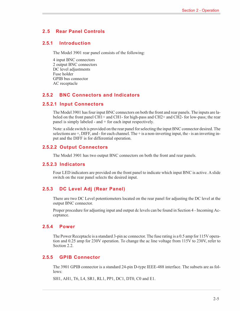
Each channel of the 3901 has a roll-off rate of 115dB/octave. The amplitude response characteris-tics is shown in Figure 2.1.
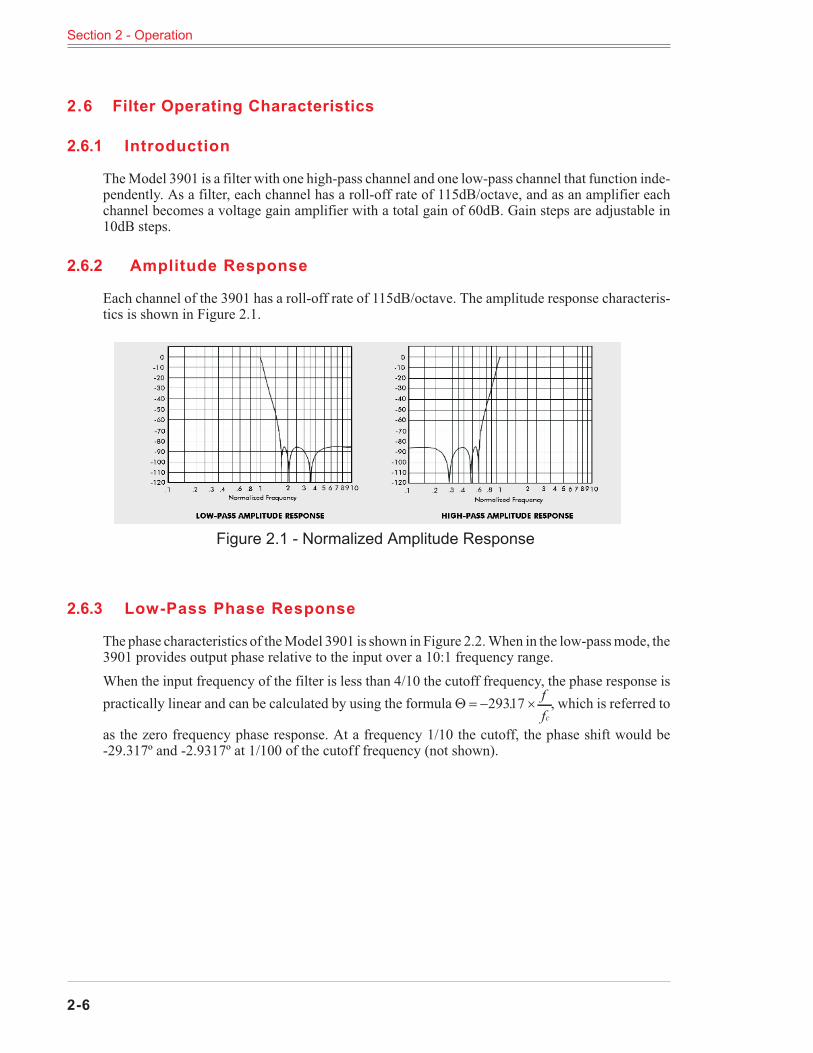
2.6.3 Low-Pass Phase Response
The phase characteristics of theModel 3901 is shown in Figure 2.2.When in the low-passmode, the3901 provides output phase relative to the input over a 10:1 frequency range.When the input frequency of the filter is less than 4/10 the cutoff frequency, the phase response ispractically linear and can be calculated by using the formula� � � �29317. f
fc
, which is referred to
as the zero frequency phase response. At a frequency 1/10 the cutoff, the phase shift would be-29.317º and -2.9317º at 1/100 of the cutoff frequency (not shown).
Section 2 - Operation
2-6
Figure 2.1 - Normalized Amplitude Response
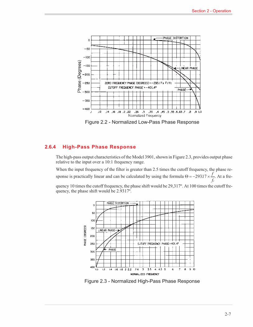
2.6.4 High-Pass Phase Response
The high-pass output characteristics of theModel 3901, shown in Figure 2.3, provides output phaserelative to the input over a 10:1 frequency range.When the input frequency of the filter is greater than 2.5 times the cutoff frequency, the phase re-sponse is practically linear and can be calculated by using the formula � � � �29317. f
fc
. At a fre-
quency 10 times the cutoff frequency, the phase shift would be 29,317º. At 100 times the cutoff fre-quency, the phase shift would be 2.9317º.
Section 2 - Operation
2-7
Figure 2.3 - Normalized High-Pass Phase Response
Figure 2.2 - Normalized Low-Pass Phase Response
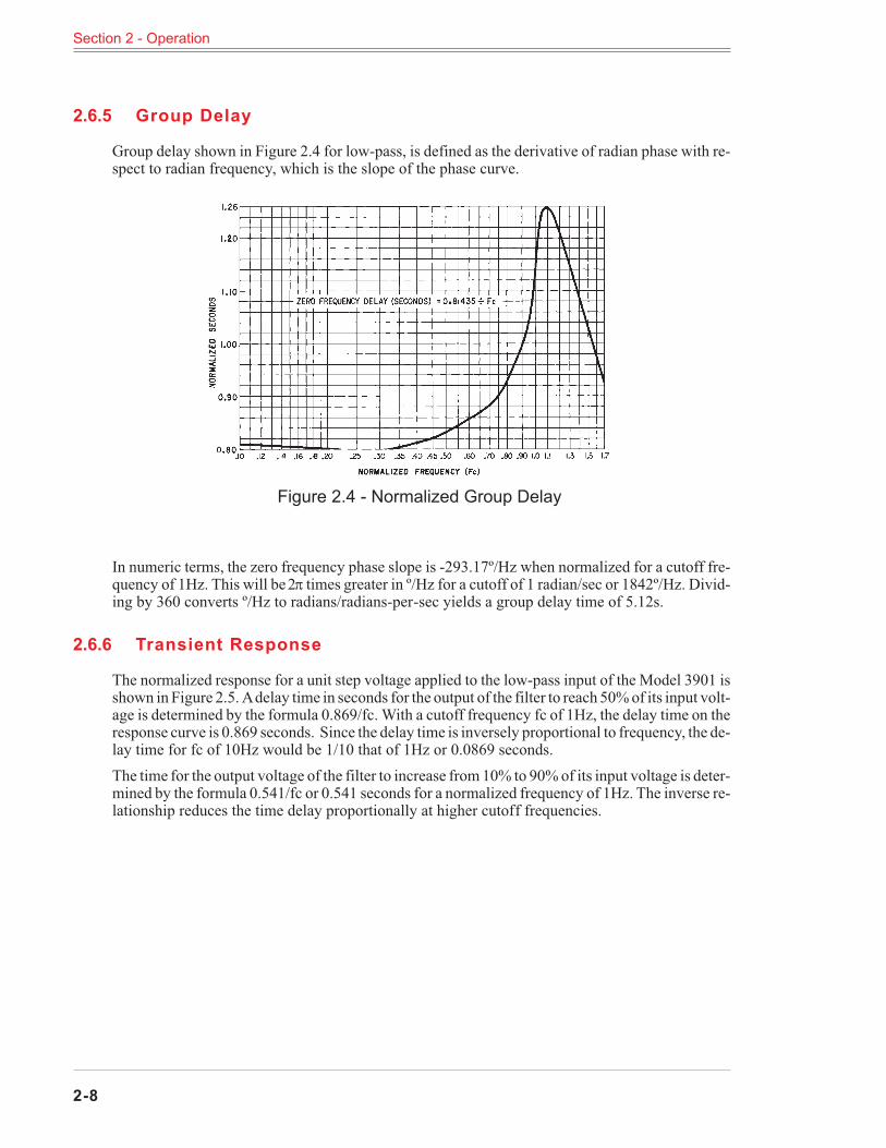
2.6.5 Group Delay
Group delay shown in Figure 2.4 for low-pass, is defined as the derivative of radian phase with re-spect to radian frequency, which is the slope of the phase curve.
In numeric terms, the zero frequency phase slope is -293.17º/Hz when normalized for a cutoff fre-quency of 1Hz. This will be2� times greater in º/Hz for a cutoff of 1 radian/sec or 1842º/Hz. Divid-ing by 360 converts º/Hz to radians/radians-per-sec yields a group delay time of 5.12s.
2.6.6 Transient Response
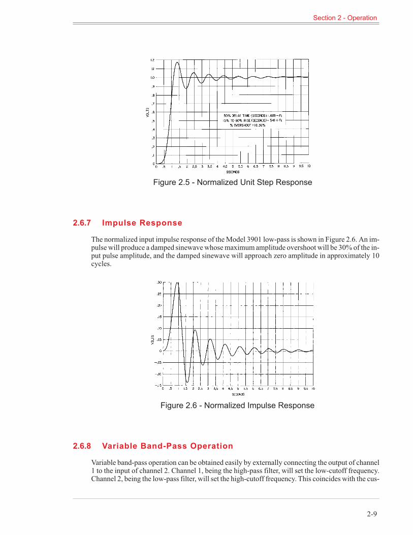
The normalized response for a unit step voltage applied to the low-pass input of the Model 3901 isshown in Figure 2.5. Adelay time in seconds for the output of the filter to reach 50%of its input volt-age is determined by the formula 0.869/fc. With a cutoff frequency fc of 1Hz, the delay time on theresponse curve is 0.869 seconds. Since the delay time is inversely proportional to frequency, the de-lay time for fc of 10Hz would be 1/10 that of 1Hz or 0.0869 seconds.The time for the output voltage of the filter to increase from10% to 90%of its input voltage is deter-mined by the formula 0.541/fc or 0.541 seconds for a normalized frequency of 1Hz. The inverse re-lationship reduces the time delay proportionally at higher cutoff frequencies.
Section 2 - Operation
2-8
Figure 2.4 - Normalized Group Delay
2.6.7 Impulse Response
The normalized input impulse response of theModel 3901 low-pass is shown in Figure 2.6. An im-pulsewill produce a damped sinewavewhosemaximumamplitude overshoot will be 30%of the in-put pulse amplitude, and the damped sinewave will approach zero amplitude in approximately 10cycles.
2.6.8 Variable Band-Pass Operation
Variable band-pass operation can be obtained easily by externally connecting the output of channel1 to the input of channel 2. Channel 1, being the high-pass filter, will set the low-cutoff frequency.Channel 2, being the low-pass filter, will set the high-cutoff frequency. This coincides with the cus-
Section 2 - Operation
2-9
Figure 2.6 - Normalized Impulse Response
Figure 2.5 - Normalized Unit Step Response
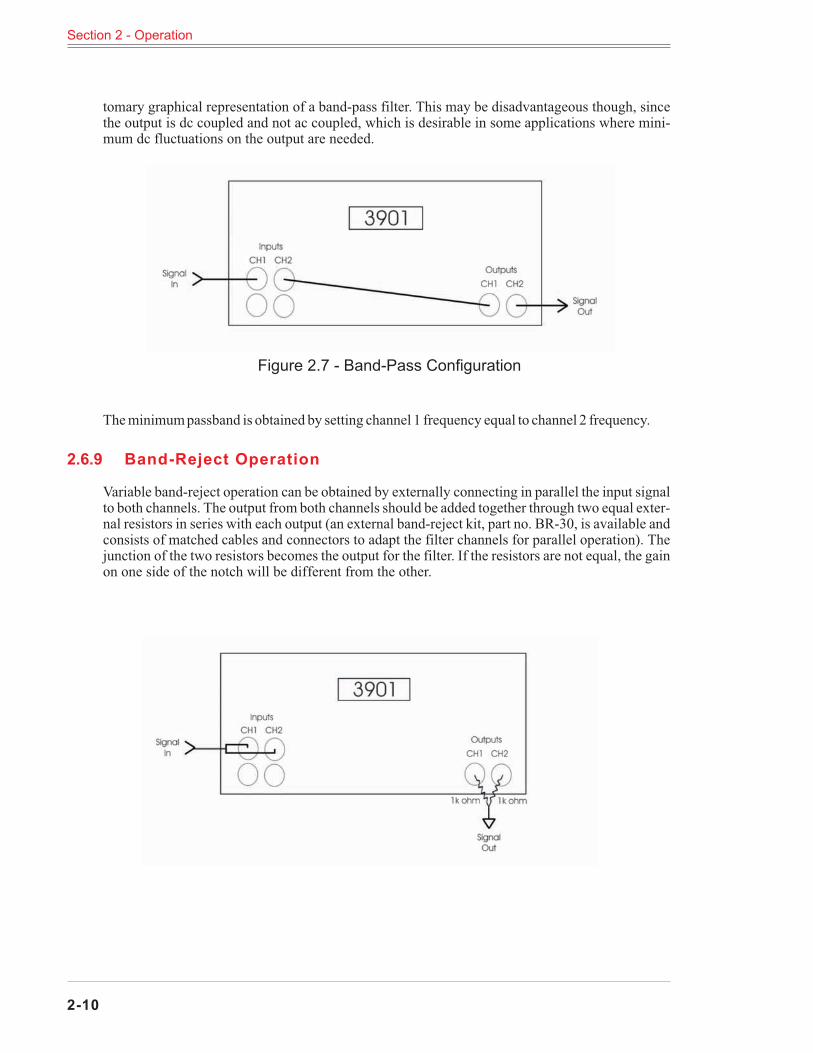
tomary graphical representation of a band-pass filter. This may be disadvantageous though, sincethe output is dc coupled and not ac coupled, which is desirable in some applications where mini-mum dc fluctuations on the output are needed.
Theminimumpassband is obtained by setting channel 1 frequency equal to channel 2 frequency.
2.6.9 Band-Reject Operation
Variable band-reject operation can be obtained by externally connecting in parallel the input signalto both channels. The output from both channels should be added together through two equal exter-nal resistors in series with each output (an external band-reject kit, part no. BR-30, is available andconsists of matched cables and connectors to adapt the filter channels for parallel operation). Thejunction of the two resistors becomes the output for the filter. If the resistors are not equal, the gainon one side of the notch will be different from the other.
Section 2 - Operation
2-10
Figure 2.7 - Band-Pass Configuration
Sect ion 3
GPIB Programming
3.1 Introduction
TheModel 3901 remote programming interface accepts both ASCII data commands and IEEE-488standard commands (ATN true) for control of the unit remotely.In presenting the information required to program the Model 3901 via the GPIB bus, this manualpresupposes a user knowledge of both ASCII data and IEEE-488 bus commands.
3.2 Preliminary Programming Information
3.2.1 GPIB Primary Bus Address
The GPIB primary address and software line-termination-character-sequence (LTCS) selection isset via the front panel keyboard as listed in Table 3.1 and 3.2. These two parameters are stored innon-volatile memory and will be remembered by the 3901 indefinitely, even when the power to theunit is removed. They do not need to be re-entered each time the unit is turned on.The LTCS affects the GPIB in the Talker mode only (data output from the 3901 to the GPIB). Afterthe printable characters have been sent, non-printable characters, such as carriage return (CR) andline feed (LF), are often required to achieve the desired results in various computers. Table 3.2 liststhe various key sequences with the LTCS it selects.
Setting and Displaying the GPIB Primary Address
Function Keyboard Entry
To set the primary address from 0 to 30 [X][SHIFT][MEGA]To display the primary address [SHIFT][MEGA]
Table 3.1
Section 3 - GPIB Programming
3-1
Line-Termination-Character-Sequence
Line-Termination-Character-Sequence Keyboard Entry
None (EOI only) [0][SHIFT][ALL CH]Carriage return (with EOI) [1][SHIFT][ALL CH]Line feed (with EOI) [2][SHIFT][ALL CH]Carriage return followed by line feed (with EOI) [3][SHIFT][ALL CH]Line feed followed by carriage return (with EOI) [4][SHIFT][ALL CH]Display present LTCS [SHIFT][ALL CH]
Table 3.2
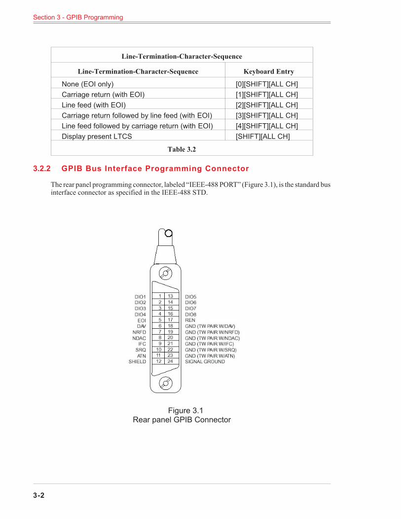
3.2.2 GPIB Bus Interface Programming Connector
The rear panel programming connector, labeled “IEEE-488 PORT” (Figure 3.1), is the standard businterface connector as specified in the IEEE-488 STD.
Section 3 - GPIB Programming
3-2
Figure 3.1Rear panel GPIB Connector
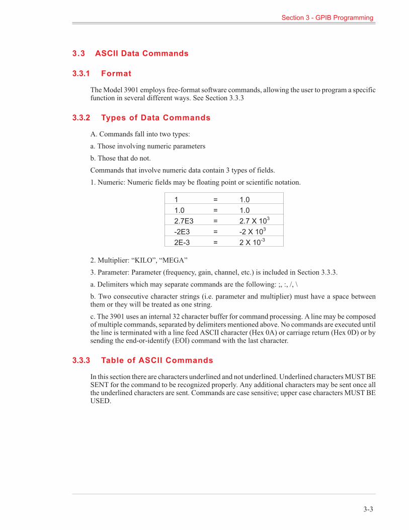
3.3 ASCII Data Commands
3.3.1 Format
TheModel 3901 employs free-format software commands, allowing the user to program a specificfunction in several different ways. See Section 3.3.3
3.3.2 Types of Data Commands
A. Commands fall into two types:a. Those involving numeric parametersb. Those that do not.Commands that involve numeric data contain 3 types of fields.1. Numeric: Numeric fields may be floating point or scientific notation.
1 = 1.01.0 = 1.02.7E3 = 2.7 X 10³
-2E3 = -2 X 10³
2E-3 = 2 X 10⁻³
2. Multiplier: “KILO”, “MEGA”3. Parameter: Parameter (frequency, gain, channel, etc.) is included in Section 3.3.3.a. Delimiters which may separate commands are the following: ;, :, /, \b. Two consecutive character strings (i.e. parameter and multiplier) must have a space betweenthem or they will be treated as one string.c. The 3901 uses an internal 32 character buffer for command processing. A line may be composedof multiple commands, separated by delimiters mentioned above. No commands are executed untilthe line is terminated with a line feed ASCII character (Hex 0A) or carriage return (Hex 0D) or bysending the end-or-identify (EOI) command with the last character.
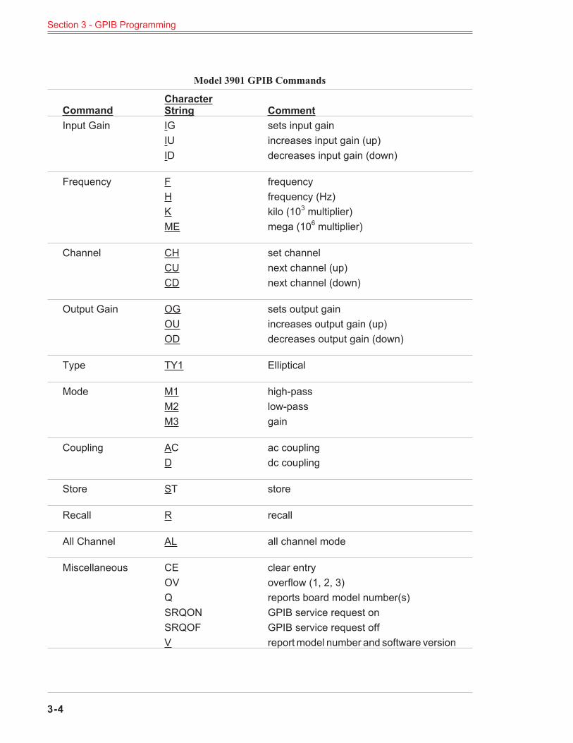
3.3.3 Table of ASCII Commands
In this section there are characters underlined and not underlined. Underlined charactersMUSTBESENT for the command to be recognized properly. Any additional characters may be sent once allthe underlined characters are sent. Commands are case sensitive; upper case characters MUST BEUSED.
Section 3 - GPIB Programming
3-3
Model 3901 GPIB Commands
CommandCharacterString Comment
Input Gain IG sets input gainIU increases input gain (up)ID decreases input gain (down)
Frequency F frequencyH frequency (Hz)K kilo (103 multiplier)ME mega (106 multiplier)
Channel CH set channelCU next channel (up)CD next channel (down)
Output Gain OG sets output gainOU increases output gain (up)OD decreases output gain (down)
Type TY1 Elliptical
Mode M1 high-passM2 low-passM3 gain
Coupling AC ac couplingD dc coupling
Store ST store
Recall R recall
All Channel AL all channel mode
Miscellaneous CE clear entryOV overflow (1, 2, 3)Q reports board model number(s)SRQON GPIB service request onSRQOF GPIB service request offV reportmodel number and software version
Section 3 - GPIB Programming
3-4
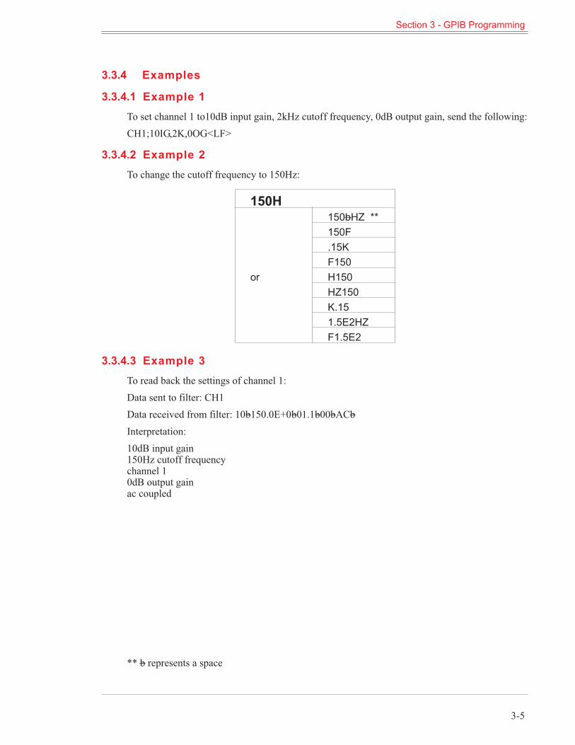
3.3.4 Examples
3.3.4.1 Example 1To set channel 1 to10dB input gain, 2kHz cutoff frequency, 0dB output gain, send the following:CH1;10IG,2K,0OG<LF>
3.3.4.2 Example 2To change the cutoff frequency to 150Hz:
150H
or
150bHZ **150F.15KF150H150HZ150K.151.5E2HZF1.5E2
3.3.4.3 Example 3To read back the settings of channel 1:Data sent to filter: CH1Data received from filter: 10b150.0E+0b01.1b00bACbInterpretation:10dB input gain150Hz cutoff frequencychannel 10dB output gainac coupled
** b represents a space
Section 3 - GPIB Programming
3-5
3.4 IEEE-488 Standard Commands
These commands are sent with ATN true as described in the standard.
3.4.1 Multi-Line Messages
IEEE-488Command Mnemonic Result
My Listen Address MLA Enables unit to receive data.Unlisten UNL Disables unit from receiving data.My Talk Address MTA Designates unit to send data.Untalk UNT Disables unit from sending data.
Local Lockout LLO
Disables return-to-local key (CEkey on front panel) such that whenin remote mode the keyboard cannot be activated by pressing a frontpanel key.
Go To Local GTLPuts unit in local control modesuch that front panel keyboard isactive.
Device Clear DCL
When the device clear command issent, the following parameters arechanged regardless of their exist-ing settings:
Input Gain = 0dBOutput Gain = 0dBResponse = EllipticalMode:HPchannel 1, LP channel 2Cutoff Frequency: 1kHzCoupling: AC
Clears current settings for bothchannels. It does not clear set-upsstored with [STORE] key. It doesnot change interface bus parame-ters and flags such as: address,SRQ, ON/OFF, parallel poll bit se-lected, etc.
Selected DeviceClear SDC
Performs same function as deviceclear (DCL) except only if unit isaddressed.
Discussion (see section 2.8 and Figure 10 of the IEEE-488 Interface Standard): Note that there are 4possible states; local, remote, local-with-lockout, and remote-with-lockout. Front panel control isconsidered local while control from the system controller is considered to be remote. Selection oflocal or local-with-lockout and remote or remote-with-lockout is done several ways.When the unitis addressed to talk (MTA) or listen (MLA), it will enter into remote.WhenGO-TO-LOCAL(GTL)is sent, it enters into local mode or local-with-lockout mode.
Section 3 - GPIB Programming
3-6
Also, if lockout mode is not invoked by the controller (local lockout command LLO), pressing the[CE] key when the remote LED is on will return control to the keyboard.Note: The lockout mode is not related to whether control is local or remote, only whether controlcan be returned to local by pressing the [CE] key.Lockout mode (local-with-lockout and remote-with-lockout vs. local and remote) is controlled bythe controller. Sending the local lockout command (LLO) selects the local-with-lockout and re-mote-with-lockout pair versus remote and local without lockout out. Lockout can only be canceledby the controller, placing the remote enable line false.
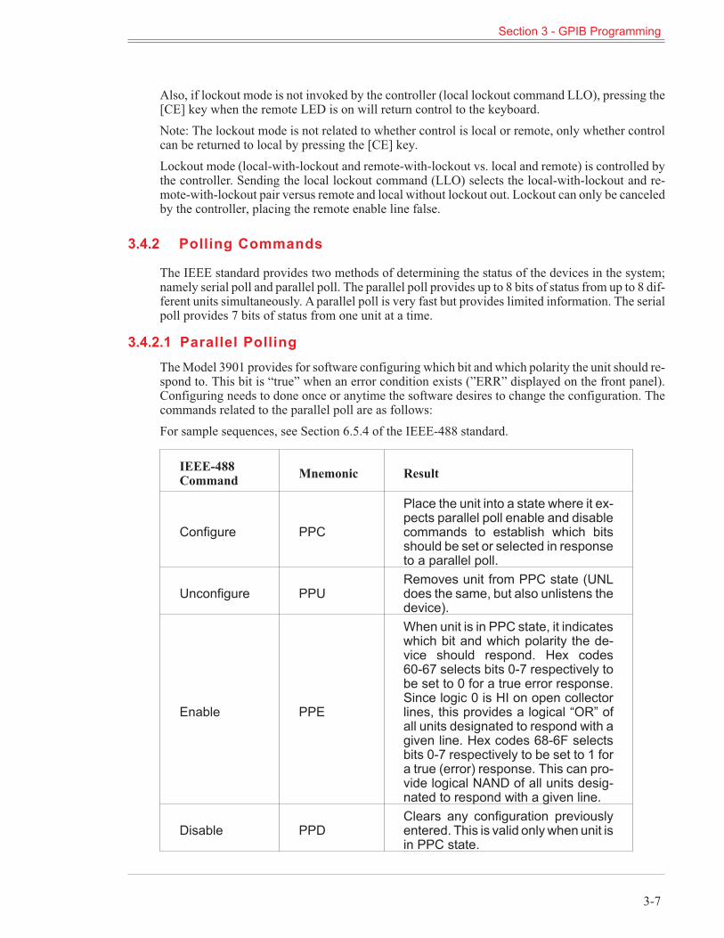
3.4.2 Polling Commands
The IEEE standard provides two methods of determining the status of the devices in the system;namely serial poll and parallel poll. The parallel poll provides up to 8 bits of status from up to 8 dif-ferent units simultaneously. Aparallel poll is very fast but provides limited information. The serialpoll provides 7 bits of status from one unit at a time.
3.4.2.1 Parallel PollingTheModel 3901 provides for software configuring which bit and which polarity the unit should re-spond to. This bit is “true” when an error condition exists (”ERR” displayed on the front panel).Configuring needs to done once or anytime the software desires to change the configuration. Thecommands related to the parallel poll are as follows:For sample sequences, see Section 6.5.4 of the IEEE-488 standard.
IEEE-488Command Mnemonic Result
Configure PPC
Place the unit into a state where it ex-pects parallel poll enable and disablecommands to establish which bitsshould be set or selected in responseto a parallel poll.
Unconfigure PPURemoves unit from PPC state (UNLdoes the same, but also unlistens thedevice).
Enable PPE
When unit is in PPC state, it indicateswhich bit and which polarity the de-vice should respond. Hex codes60-67 selects bits 0-7 respectively tobe set to 0 for a true error response.Since logic 0 is HI on open collectorlines, this provides a logical “OR” ofall units designated to respond with agiven line. Hex codes 68-6F selectsbits 0-7 respectively to be set to 1 fora true (error) response. This can pro-vide logical NAND of all units desig-nated to respond with a given line.
Disable PPDClears any configuration previouslyentered. This is valid onlywhen unit isin PPC state.
Section 3 - GPIB Programming
3-7
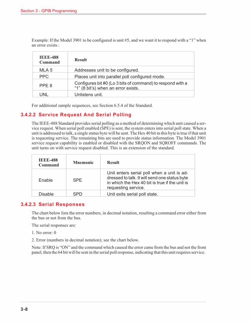
Example: If the Model 3901 to be configured is unit #5, and we want it to respond with a “1” whenan error exists.:
IEEE-488Command Result
MLA 5 Addresses unit to be configured.PPC Places unit into parallel poll configured mode.
PPE 8 Configures bit #0 (Lo 3 bits of command) to respond with a“1” (8 bit’s) when an error exists.
UNL Unlistens unit.
For additional sample sequences, see Section 6.5.4 of the Standard.
3.4.2.2 Service Request And Serial PollingThe IEEE-488 Standard provides serial polling as amethod of determiningwhich unit caused a ser-vice request. When serial poll enabled (SPE) is sent, the system enters into serial poll state.When aunit is addressed to talk, a single status byte will be sent. TheHex 40 bit in this byte is true if that unitis requesting service. The remaining bits are used to provide status information. The Model 3901service request capability is enabled or disabled with the SRQON and SQROFF commands. Theunit turns on with service request disabled. This is an extension of the standard.
IEEE-488Command Mnemonic Result
Enable SPEUnit enters serial poll when a unit is ad-dressed to talk. It will send one status bytein which the Hex 40 bit is true if the unit isrequesting service.
Disable SPD Unit exits serial poll state.
3.4.2.3 Serial ResponsesThe chart below lists the error numbers, in decimal notation, resulting a command error either fromthe bus or not from the bus.The serial responses are:1. No error: 02. Error (numbers in decimal notation); see the chart below.Note: If SRQ is “ON” and the commandwhich caused the error came from the bus and not the frontpanel, then the 64 bitwill be sent in the serial poll response, indicating that this unit requires service.
Section 3 - GPIB Programming
3-8
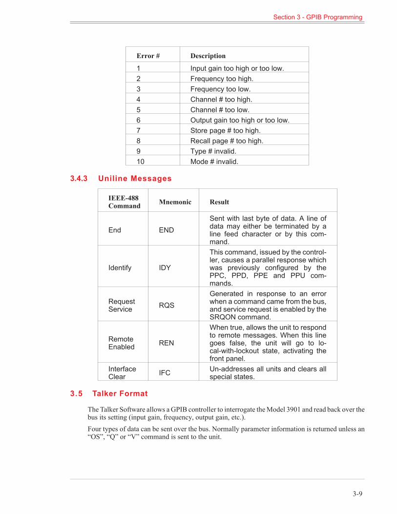
Error # Description
1 Input gain too high or too low.2 Frequency too high.3 Frequency too low.4 Channel # too high.5 Channel # too low.6 Output gain too high or too low.7 Store page # too high.8 Recall page # too high.9 Type # invalid.10 Mode # invalid.
3.4.3 Uniline Messages
IEEE-488Command Mnemonic Result
End ENDSent with last byte of data. A line ofdata may either be terminated by aline feed character or by this com-mand.
Identify IDY
This command, issued by the control-ler, causes a parallel response whichwas previously configured by thePPC, PPD, PPE and PPU com-mands.
RequestService RQS
Generated in response to an errorwhen a command came from the bus,and service request is enabled by theSRQON command.
RemoteEnabled REN
When true, allows the unit to respondto remote messages. When this linegoes false, the unit will go to lo-cal-with-lockout state, activating thefront panel.
InterfaceClear IFC Un-addresses all units and clears all
special states.
3.5 Talker Format
The Talker Software allows aGPIB controller to interrogate theModel 3901 and read back over thebus its setting (input gain, frequency, output gain, etc.).Four types of data can be sent over the bus. Normally parameter information is returned unless an“OS”, “Q” or “V” command is sent to the unit.
Section 3 - GPIB Programming
3-9
3.5.1 Parameter Information Format
1 Two digits of input gain.1a space2 Four difits including decimal for frequency or other alpha.
3
If frequency is displayed:
E+ 0 if both kilo and mega LEDs are offE+ 3 if kilo LED is on.E + 6 if mega LED is on otherwise 3 spaces.
3a space4 Two digits, a decimal and one digit for channel #.4a space5 Two digits for output gain.5a space6 “AC” if ac coupled, “DC” if dc coupled.7 “*” if all channel mode, otherwise a space.
3.5.2 Model Number and Software Version Format
After sending the “V” command, the next line of data read from theModel 3901will be as follows:KROHN-HITE 3901, V3.5The version number will reflect the revision level of the firmware in the instrument.This data is returned only once per command; after that it returns to talking what the front panel isdisplaying.
3.6 Programming Examples
The following are programming examples in Microsoft Qick Basic, Borland Turbo C and NationalInstruments IBIC.
3.6.1 Example 1 - Microsoft Quick Basic
‘ Microsoft (R) Quick Basic (tm) program for the Krohn-Hite Model 3988‘‘ * Enter this program from DOS by typing: QB 3988 /LQBIB.QLB‘ (the /L switch means tells Quick Basic to load a library)‘‘ * Set the instrument to GPIB address 1:‘ Press 1 [SECOND FUNCTION] [MEGA]‘‘ * Set the instrument for no carriage return or line feed (EOI only):‘ Press 0 [SECOND FUNCTION] [ALL CHAN]
Section 3 - GPIB Programming
3-10
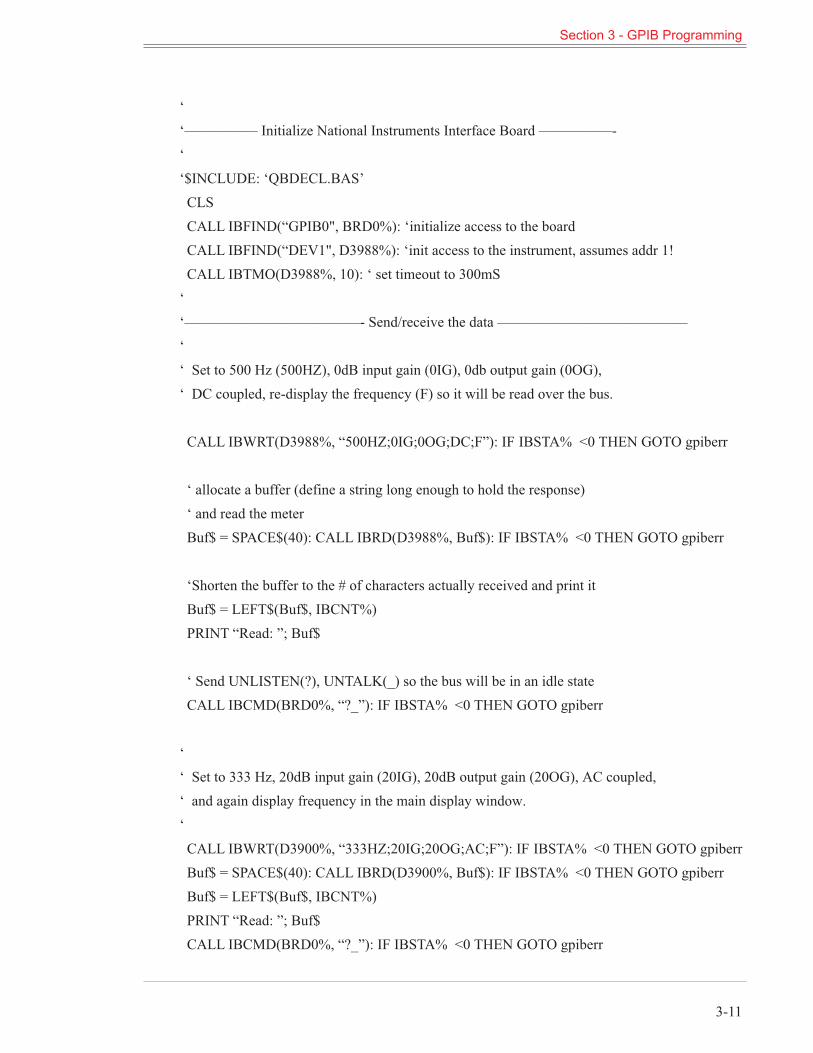
‘‘————— Initialize National Instruments Interface Board —————-‘‘$INCLUDE: ‘QBDECL.BAS’CLSCALL IBFIND(“GPIB0", BRD0%): ‘initialize access to the boardCALL IBFIND(“DEV1", D3988%): ‘init access to the instrument, assumes addr 1!CALL IBTMO(D3988%, 10): ‘ set timeout to 300mS‘‘————————————- Send/receive the data —————————————‘‘ Set to 500 Hz (500HZ), 0dB input gain (0IG), 0db output gain (0OG),‘ DC coupled, re-display the frequency (F) so it will be read over the bus.
CALL IBWRT(D3988%, “500HZ;0IG;0OG;DC;F”): IF IBSTA% <0 THEN GOTO gpiberr
‘ allocate a buffer (define a string long enough to hold the response)‘ and read the meterBuf$ = SPACE$(40): CALL IBRD(D3988%, Buf$): IF IBSTA% <0 THEN GOTO gpiberr
‘Shorten the buffer to the # of characters actually received and print itBuf$ = LEFT$(Buf$, IBCNT%)PRINT “Read: ”; Buf$
‘ Send UNLISTEN(?), UNTALK(_) so the bus will be in an idle stateCALL IBCMD(BRD0%, “?_”): IF IBSTA% <0 THEN GOTO gpiberr
‘‘ Set to 333 Hz, 20dB input gain (20IG), 20dB output gain (20OG), AC coupled,‘ and again display frequency in the main display window.‘CALL IBWRT(D3900%, “333HZ;20IG;20OG;AC;F”): IF IBSTA% <0 THEN GOTO gpiberrBuf$ = SPACE$(40): CALL IBRD(D3900%, Buf$): IF IBSTA% <0 THEN GOTO gpiberrBuf$ = LEFT$(Buf$, IBCNT%)PRINT “Read: ”; Buf$CALL IBCMD(BRD0%, “?_”): IF IBSTA% <0 THEN GOTO gpiberr
Section 3 - GPIB Programming
3-11
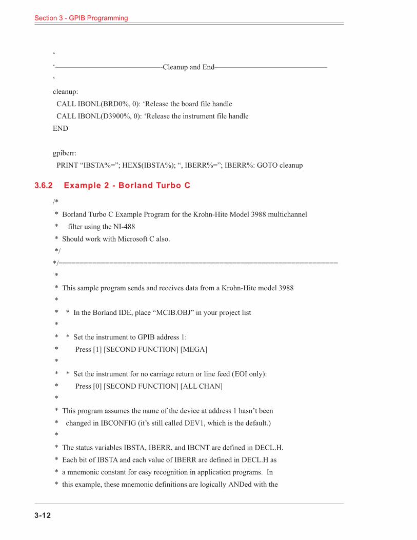
‘‘——————————————-Cleanup and End———————————————‘cleanup:CALL IBONL(BRD0%, 0): ‘Release the board file handleCALL IBONL(D3900%, 0): ‘Release the instrument file handleEND
gpiberr:PRINT “IBSTA%=”; HEX$(IBSTA%); “, IBERR%=”; IBERR%: GOTO cleanup
3.6.2 Example 2 - Borland Turbo C
/** Borland Turbo C Example Program for the Krohn-Hite Model 3988 multichannel* filter using the NI-488* Should work with Microsoft C also.*/*/==================================================================** This sample program sends and receives data from a Krohn-Hite model 3988** * In the Borland IDE, place “MCIB.OBJ” in your project list** * Set the instrument to GPIB address 1:* Press [1] [SECOND FUNCTION] [MEGA]** * Set the instrument for no carriage return or line feed (EOI only):* Press [0] [SECOND FUNCTION] [ALL CHAN]** This program assumes the name of the device at address 1 hasn’t been* changed in IBCONFIG (it’s still called DEV1, which is the default.)** The status variables IBSTA, IBERR, and IBCNT are defined in DECL.H.* Each bit of IBSTA and each value of IBERR are defined in DECL.H as* a mnemonic constant for easy recognition in application programs. In* this example, these mnemonic definitions are logically ANDed with the
Section 3 - GPIB Programming
3-12
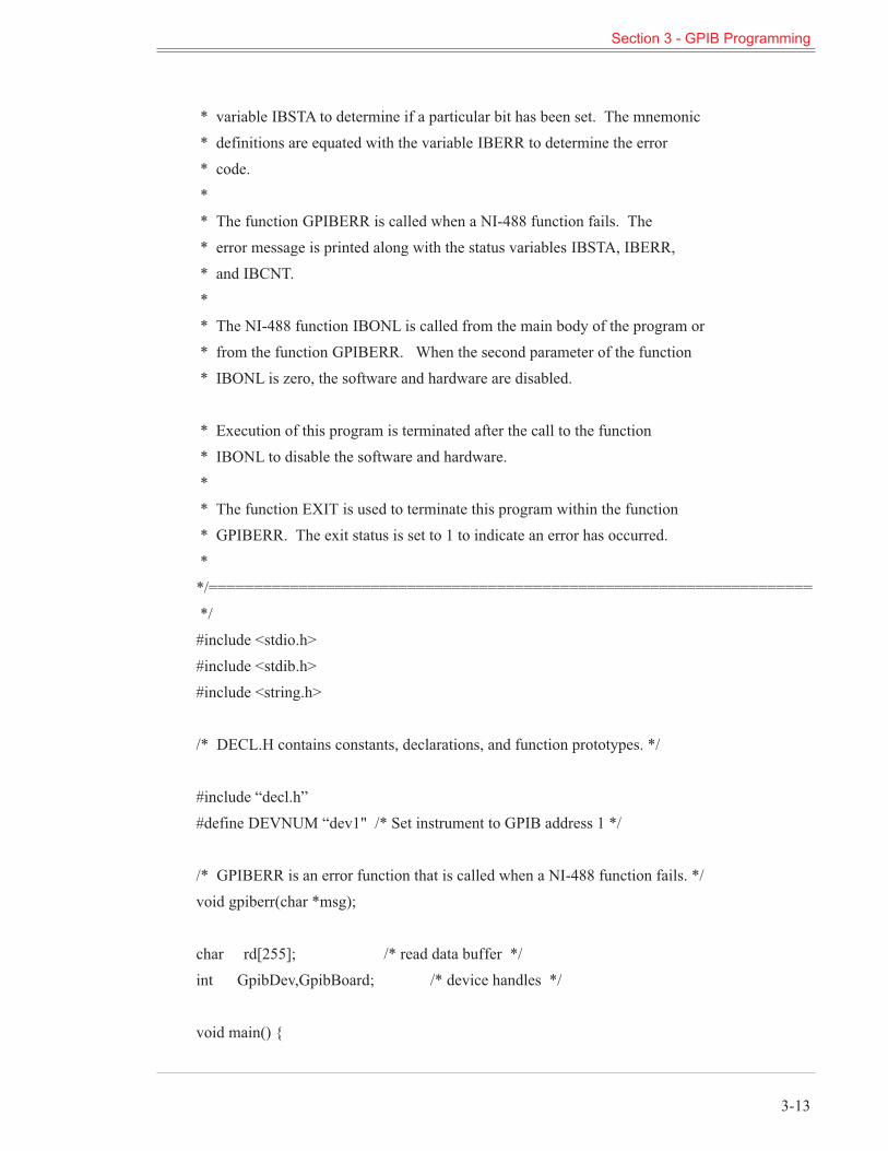
* variable IBSTA to determine if a particular bit has been set. The mnemonic* definitions are equated with the variable IBERR to determine the error* code.** The function GPIBERR is called when a NI-488 function fails. The* error message is printed along with the status variables IBSTA, IBERR,* and IBCNT.** The NI-488 function IBONL is called from the main body of the program or* from the function GPIBERR. When the second parameter of the function* IBONL is zero, the software and hardware are disabled.
* Execution of this program is terminated after the call to the function* IBONL to disable the software and hardware.** The function EXIT is used to terminate this program within the function* GPIBERR. The exit status is set to 1 to indicate an error has occurred.**/===================================================================*/#include <stdio.h>#include <stdib.h>#include <string.h>
/* DECL.H contains constants, declarations, and function prototypes. */
#include “decl.h”#define DEVNUM “dev1" /* Set instrument to GPIB address 1 */
/* GPIBERR is an error function that is called when a NI-488 function fails. */void gpiberr(char *msg);
char rd[255]; /* read data buffer */int GpibDev,GpibBoard; /* device handles */
void main() {
Section 3 - GPIB Programming
3-13
printf(“\nSending data to the Krohn-Hite model 3988...\n”);printf(“\n”);
/** Assign a unique identifier (a ‘handle’) to the K-H 3988 and store it in the* variable GpibDev. If GpibDev is less than zero, call GPIBERR with an error* message.*/GpibDev = ibfind (DEVNUM);if (GpibDev <0) gpiberr(“ibfind Error”);
/** Assign a handle to the GPIB board so we can use ibcmd to send board* level commands such as UNL and UNT.*/GpibBoard = ibfind (“gpib0");if (GpibBoard <0) gpiberr(“ibfind Error”);
/** Clear the K-H 3988 to its default state. The settings vary depending on the* type of board in each channel. These settings are listed in the GPIB* section of the manual for each filter board (not the 3988 manual).* If the error bit ERR is set in IBSTA, call GPIBERR with an error message.*/ibclr (GpibDev);if (ibsta & ERR) gpiberr(“ibclr Error”);
/** Write a string out to the K-H 3988.* If the error bit ERR is set in IBSTA, call GPIBERR with an error message.*/ibwrt (GpibDev,"500HZ;0IG;0OG;DC;F",18L); /* the ‘F’ displays the frequency so when*/if (ibsta & ERR) gpiberr(“ibwrt Error”); /* we read the unit we’ll see the freq */
Section 3 - GPIB Programming
3-14
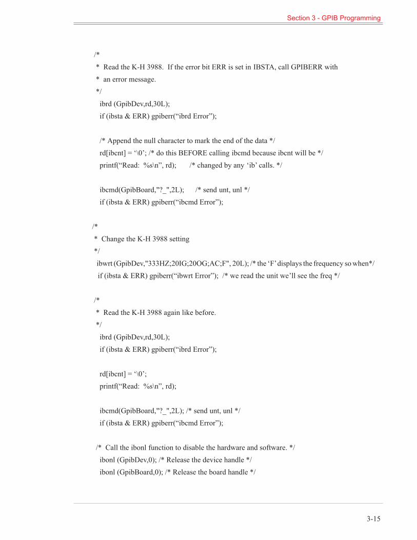
/** Read the K-H 3988. If the error bit ERR is set in IBSTA, call GPIBERR with* an error message.*/ibrd (GpibDev,rd,30L);if (ibsta & ERR) gpiberr(“ibrd Error”);
/* Append the null character to mark the end of the data */rd[ibcnt] = ‘\0’; /* do this BEFORE calling ibcmd because ibcnt will be */printf(“Read: %s\n”, rd); /* changed by any ‘ib’ calls. */
ibcmd(GpibBoard,"?_",2L); /* send unt, unl */if (ibsta & ERR) gpiberr(“ibcmd Error”);
/** Change the K-H 3988 setting*/ibwrt (GpibDev,"333HZ;20IG;20OG;AC;F", 20L); /* the ‘F’displays the frequency sowhen*/if (ibsta & ERR) gpiberr(“ibwrt Error”); /* we read the unit we’ll see the freq */
/** Read the K-H 3988 again like before.*/ibrd (GpibDev,rd,30L);if (ibsta & ERR) gpiberr(“ibrd Error”);
rd[ibcnt] = ‘\0’;printf(“Read: %s\n”, rd);
ibcmd(GpibBoard,"?_",2L); /* send unt, unl */if (ibsta & ERR) gpiberr(“ibcmd Error”);
/* Call the ibonl function to disable the hardware and software. */ibonl (GpibDev,0); /* Release the device handle */ibonl (GpibBoard,0); /* Release the board handle */
Section 3 - GPIB Programming
3-15
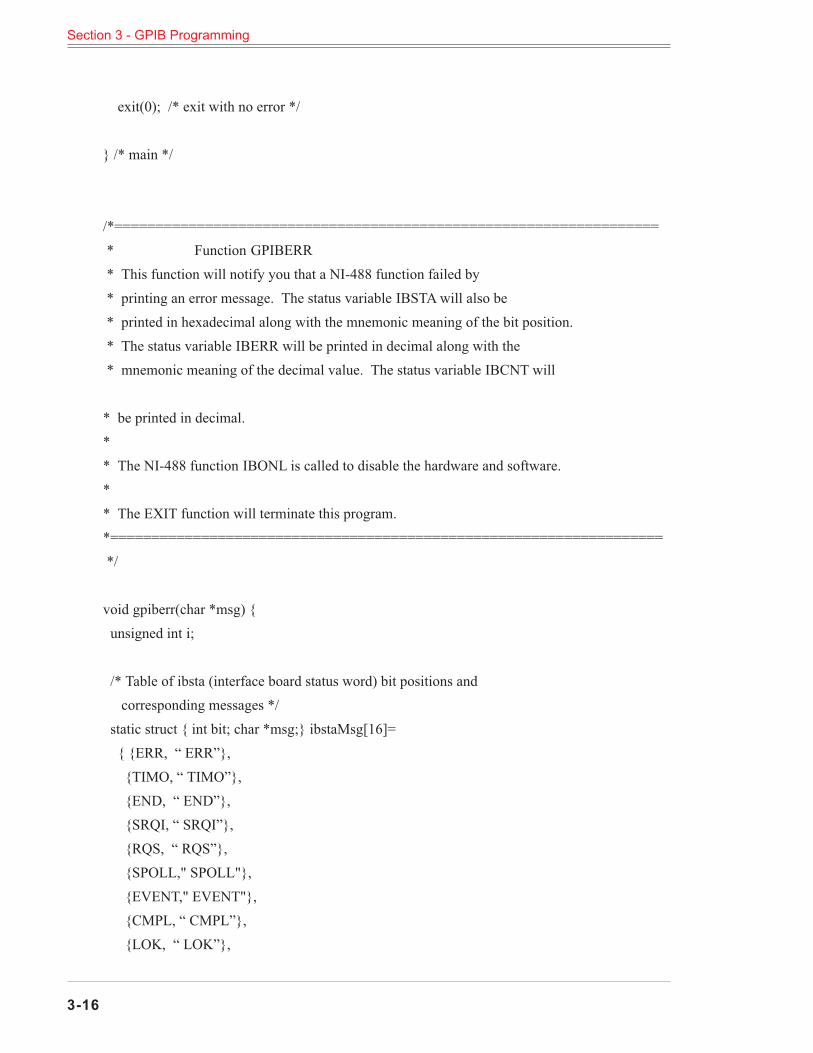
exit(0); /* exit with no error */
} /* main */
/*==================================================================* Function GPIBERR* This function will notify you that a NI-488 function failed by* printing an error message. The status variable IBSTAwill also be* printed in hexadecimal along with the mnemonic meaning of the bit position.* The status variable IBERR will be printed in decimal along with the* mnemonic meaning of the decimal value. The status variable IBCNT will
* be printed in decimal.** The NI-488 function IBONL is called to disable the hardware and software.** The EXIT function will terminate this program.*===================================================================*/
void gpiberr(char *msg) {unsigned int i;
/* Table of ibsta (interface board status word) bit positions andcorresponding messages */static struct { int bit; char *msg;} ibstaMsg[16]={ {ERR, “ ERR”},{TIMO, “ TIMO”},{END, “ END”},{SRQI, “ SRQI”},{RQS, “ RQS”},{SPOLL," SPOLL"},{EVENT," EVENT"},{CMPL, “ CMPL”},{LOK, “ LOK”},
Section 3 - GPIB Programming
3-16
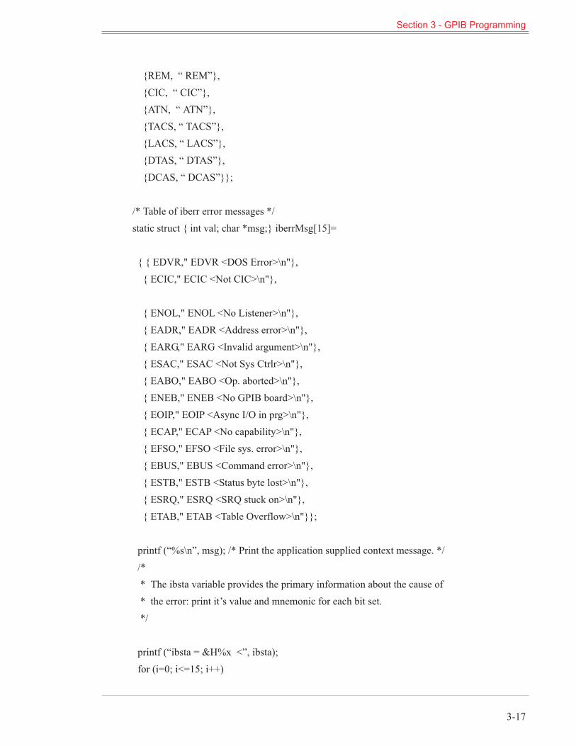
{REM, “ REM”},{CIC, “ CIC”},{ATN, “ ATN”},{TACS, “ TACS”},{LACS, “ LACS”},{DTAS, “ DTAS”},{DCAS, “ DCAS”}};
/* Table of iberr error messages */static struct { int val; char *msg;} iberrMsg[15]=
{ { EDVR," EDVR <DOS Error>\n"},{ ECIC," ECIC <Not CIC>\n"},
{ ENOL," ENOL <No Listener>\n"},{ EADR," EADR <Address error>\n"},{ EARG," EARG <Invalid argument>\n"},{ ESAC," ESAC <Not Sys Ctrlr>\n"},{ EABO," EABO <Op. aborted>\n"},{ ENEB," ENEB <No GPIB board>\n"},{ EOIP," EOIP <Async I/O in prg>\n"},{ ECAP," ECAP <No capability>\n"},{ EFSO," EFSO <File sys. error>\n"},{ EBUS," EBUS <Command error>\n"},{ ESTB," ESTB <Status byte lost>\n"},{ ESRQ," ESRQ <SRQ stuck on>\n"},{ ETAB," ETAB <Table Overflow>\n"}};
printf (“%s\n”, msg); /* Print the application supplied context message. *//** The ibsta variable provides the primary information about the cause of* the error: print it’s value and mnemonic for each bit set.*/
printf (“ibsta = &H%x <”, ibsta);for (i=0; i<=15; i++)
Section 3 - GPIB Programming
3-17
{ if (ibsta & ibstaMsg[i].bit) printf (“%s”,ibstaMsg[i].msg); };printf (“ >\n”);/** Print the iberr value and interpertation*/
printf (“iberr = %d”, iberr);for (i=0; i<=14; i++){ if (iberr==iberrMsg[i].val) printf (“%s”,iberrMsg[i].msg); };/** Print ibcnt in decimal*/
printf (“ibcnt = %d\n”, ibcnt);
printf (“\n”);/* put the board and device offline */ibonl (GpibDev,0); /* Release the device handle */ibonl (GpibBoard,0); /* Release the board handle */exit(1); /* exit with status=1 to indicate error */
3.6.3 Example 3 - National Instruments IBICPreparation:Your c:\config.sys file must have the following line in it:
device=c:\488\gpib.com
After you add this line, you must re-boot (reset) your computer for the driver to be loaded.For purposes of this demo, set the Krohn-Hite Model 3988 to GPIB address 1:Press [1][SECOND FUNCTION][MEGA]Set the talker to only send EOI:Press [1][SECOND FUNCTION][ALLCHAN]
Prompt Command You Type Comments
C:\488> IBIC From the DOS command line, enterthe IBIC program.
: ibfind gpib0 Initialize the program to access theboard.
gpib0: ibfind dev1 Initialize the program to access thedevice at GPIB address 1.
Section 3 - GPIB Programming
3-18
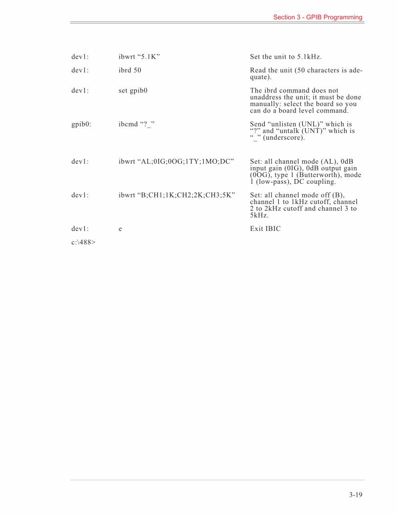
dev1: ibwrt “5.1K” Set the unit to 5.1kHz.
dev1: ibrd 50 Read the unit (50 characters is ade-quate).
dev1: set gpib0 The ibrd command does notunaddress the unit; it must be donemanually: select the board so youcan do a board level command.
gpib0: ibcmd “?_” Send “unlisten (UNL)” which is“?” and “untalk (UNT)” which is“_” (underscore).
dev1: ibwrt “AL;0IG;0OG;1TY;1MO;DC” Set: all channel mode (AL), 0dBinput gain (0IG), 0dB output gain(0OG), type 1 (Butterworth), mode1 (low-pass), DC coupling.
dev1: ibwrt “B;CH1;1K;CH2;2K;CH3;5K” Set: all channel mode off (B),channel 1 to 1kHz cutoff, channel2 to 2kHz cutoff and channel 3 to5kHz.
dev1: e Exit IBIC
c:\488>
Section 3 - GPIB Programming
3-19
This page intentionally lef t blank.
Section 3 - GPIB Programming
3-20
Sect ion 4
Incoming Acceptance
4.1 Introduction
The following procedure should be used to verify that theModel 3901 Programmable Filter is oper-ating within specifications.These checksmay be used for incoming acceptance and periodic performance checks. Checksmustbe made with all covers in place and operating for a minimum time of 1/2 hour to reach operatingtemperature. Before testing, follow the initial set-up and operating procedures given in Section 2 ofthis manual.
4.2 Required Test Equipment
The test equipment below is required to perform the following tests.
a. RC Oscillator with a frequency range from 0.01Hz to 1MHz: Krohn-Hite Model4100A or equivalent.
b.RC Oscillator with a frequency range from 10Hz to 10MHz. Frequency re-sponse of ±0.025dB from 10Hz to 500kHz: Krohn-Hite Model 4200B/4300B orequivalent.
c. Oscilloscope, bandwidth from DC to 50MHz, vertical input sensitivity of5mV/cm: Tektronix 465 or equivalent.
d. DCVoltmeter (DVM) capable ofmeasuring 1mV to 20V: Fluke 8920A or equiva-lent.
e. AC Voltmeter capable of measuring 100µV to 10Vrms: Fluke 8920A or equiva-lent.
f. Frequency Counter
4.3 Channel 1 - High-Pass
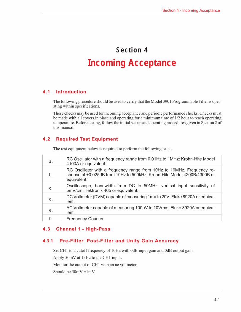
4.3.1 Pre-Filter. Post-Filter and Unity Gain Accuracy
Set CH1 to a cutoff frequency of 10Hz with 0dB input gain and 0dB output gain.Apply 50mV at 1kHz to the CH1 input.Monitor the output of CH1 with an ac voltmeter.Should be 50mV ±1mV.
Section 4 - Incoming Acceptance
4-1
Set the input (pre-filter) gain of CH1 to 10dB, 20dB, 30dB and 40dB.Connect the Fluke 8920A to the output of CH1.Reading should be within ±0.2dB at all four gain settings.
Set CH1 input gain to 0dB and apply a 0.7Vrms signal to the CH1 input.Monitor the output of CH1 with an ac voltmeter and record the output voltage.Set the output (post-filter) gain to 10dB and 20dB.Connect the Fluke 8920A to CH1 output.Readings should be ±0.2dB on both settings.
4.3.2 Low Bands Ripple Response
Connect RC Oscillator at 3Vrms at 9kHz to CH1 input.Set the cutoff frequency of the filter to 90Hz.Set the input and output gain of the filter to 0dB.Monitor the output of CH1 with ac voltmeter.Record the voltages and use as a reference.
Check the response of the 3 peaks at 189Hz, 110Hz and 90.9Hz.Check the response of all three valleys at 363Hz, 134Hz and 97.1Hz.The adjacent peak-to-valley ripple should not exceed 0.4dB.
4.3.3 High Band Ripple Response
Connect RC Oscillator at 3Vrms at 10kHz to CH1 input.Set the cutoff frequency of the filter to 100Hz.Set the input and output gain of the filter to 0dB.Monitor the output of CH1 with ac voltmeter.Record the voltages and use as a reference.
Set the filter to 10kHz.Check the response of the 3 peaks at 20.1kHz, 12.2kHz and 10.1kHz.Check the response of all three valleys at 40.3Hz, 14.9kHz and 10.8kHz.The adjacent peak-to-valley ripple should not exceed 0.4dB.
Note: Check the accuracy of the ac voltmeter at low frequencies. If necessary, compare the outputwith the input to eliminate any error.
Section 4 - Incoming Acceptance
4-2
4.3.4 Stopband Attenuation
4.3.4.1 Band 1Set the filter to 90Hz with 0dB input gain and 20dB output gain.Set RC Oscillator to 52.3Hz at 7Vrms.Connect oscilloscope to output of CH1.Signal should be <20mV p-p.Set RC Oscillator to 48.0Hz, 34.8Hz and 12.9Hz.Signal should be <20mV p-p.(Disregard the noise contained within the signal or use a 10kHz low-pass filter.)
4.3.4.2 Band 2Same as Band 1 setting the filter to 100Hz and RC Oscillator to 58.1Hz, 53.4Hz, 38.6Hz and14.3Hz.
4.3.4.3 Band 3SameasBand 1 setting the filter to 1kHz andRCOscillator to 581Hz, 534Hz, 386Hz and 143Hz.
4.3.4.4 Band 4Same as Band 1 setting filter to 10kHz and RC Oscillator to 5.81kHz, 5.34kHz, 3.86kHz and1.43kHz.
4.3.5 Cutoff Frequency Accuracy
Connect the RC Oscillator at 3Vrms at 900Hz to CH1 input.Set filter cutoff to 10Hz with 0dB input and output gain.Monitor the output of CH1 with AC Voltmeter. Record the voltage at the output.Set the filter to 900Hz. Adjust the input frequency near 891Hz to obtain -0.22dB (0.077V).Frequency should be between 873Hz and 909Hz.
Set filter and RC Oscillator to 90Hz.Adjust RC Oscillator frequency for -0.22dB.Frequency should read between 87.3Hz and 90.9Hz.
Set filter and RC Oscillator to 1kHz.Adjust RC Oscillator frequency for -0.22dB.Frequency should read between 970Hz and 1.01kHz.Set filter and RC Oscillator to 10kHz.Adjust RC Oscillator frequency for -0.22dB.Frequency should read between 9.70kHz and 10.1kHz.
Section 4 - Incoming Acceptance
4-3
4.3.6 Noise Measurements (2MHz Detector Bandwidth)
Short CH1 input.Connect an ac voltmeter to the CH1 output.Set the filter 1kHz with 0dB input and output gain.Output should be <400µVrms.
Set input gain to 40dB and output gain to 20dB.Output should be <20mVrms.
Set the filter to 99kHz with 0dB input and output gain.Output should be <1mVrms.
Set the filter to the Gain Mode.Set input gain and output gain to 0dB.Output should be <150µVrms.Set input gain to 40dB and output gain to 20dB.Output should be <25mVrms.
4.4 Channel 2 - Low-Pass
4.4.1 Pre-Filter, Post-Filter, and Unity Gain Accuracy
Set CH2 to a cutoff frequency of 9kHz with 0dB input gain and 0dB output gain.Apply 50mV at 100Hz to the CH2 input.Monitor the output of CH2 with an ac voltmeter.Should be 50mV ±1mV.
Set the input (pre-filter) gain of CH2 to 10dB, 20dB, 30dB and 40dB.Connect the Fluke 8920A to the output of CH2.Reading should be within ±0.2dB at all four gain settings.
Set CH2 input gain to 0dB and apply a 0.7Vrms signal to the CH2 input.Monitor the output of CH2 with an ac voltmeter and record the output voltage.Set the output (post-filter) gain to 10dB and 20dB.Connect the Fluke 8920A to CH2 output.Readings should be ±0.2dB on both settings.
Section 4 - Incoming Acceptance
4-4
4.4.2 Low Band Ripple Response
Connect RC Oscillator at 3Vrms at 50Hz to CH2 input.Set the cutoff frequency of the filter to 900Hz.Set the input and output gain of the filter to 0dB.Monitor the output of CH2 with ac voltmeter.Record the voltages and use as a reference.Set filter to 90Hz.
Check the response of the 3 peaks at 42.9Hz, 73.9Hz and 89.1Hz.Check the response of all three valleys at 22.3Hz, 60.3Hz and 83.4Hz.The adjacent peak-to-valley ripple should not exceed 0.4dB.
4.4.3 High Band Ripple Response
Connect RC Oscillator at 3Vrms at 100Hz to CH2 input.Set the cutoff frequency of the filter to 10kHz.Set the input and output gain of the filter to 0dB.Monitor the output of CH2 with ac voltmeter.Record the voltages and use as a reference.
Check the response of the 3 peaks at 4.7kHz, 8.2kHz and 9.9kHz.Check the response of all three valleys at 2.4kHz, 6.8kHz and 9.2kHz.The adjacent peak-to-valley ripple should not exceed 0.4dB.
Note: Check the accuracy of the ac voltmeter at low frequencies. If necessary, compare the outputwith the input to eliminate any error.
4.4.4 Stopband Attenuation
4.4.4.1 Band 1Set the filter to 10Hz with 0dB input gain and 20dB output gain.Set RC Oscillator to 17.5Hz at 7Vrms.Connect oscilloscope to output of CH2.Signal should be <20mV p-p.Set RC Oscillator to 18.7Hz, 25.9Hz and 70Hz.Signal should be <20mV p-p.
Section 4 - Incoming Acceptance
4-5
4.4.4.2 Band 2SameasBand 1 setting the filter to 100Hz andRCOscillator to 175Hz, 187Hz, 259Hz and 700Hz.
4.4.4.3 Band 4Same as Band 1 setting the filter to 10kHz and RC Oscillator to 17.5Hz, 18.7kHz, 25.9kHz and70.0kHz.
4.4.5 Cutoff Frequency Accuracy
Connect RCOscillator at 3Vrms at 42.9Hz to the input ofCH1. Set filter to 90Hzwith 0dB input andoutput gain. Monitor the output with the ACVoltmeter. Record the voltage at the output. Adjust in-put frequency near 90.9Hz to obtain -0.22dB. Frequency should be between 89.12Hz and 92.7Hz.Set filter and RC Oscillator to 100Hz. Adjust the RC Oscillator frequency for -0.22dB. Frequencyshould read between 99Hz and 103Hz.Set filter and the RC Oscillator to 10kHz. Adjust the RC Oscillator frequency for -0.22dB. Fre-quency should be between 9.9kHz and 10.3kHz.
4.4.6 Noise Measurements (2MHz Detector Bandwidth)
Short CH2 input.Connect ac voltmeter to CH2 output.Set filter to 1kHz with 0dB input and output gain.Output should be <400µVrms.Set filter to 99kHz with 0dB input and output gain.Output should be <1mVrms.
Set filter to 99kHz with 40dB input gain and 20dB output gain.Output should be <20mVrms.
Set the filter to the Gain Mode.Set input and output gain to 0dB.Output should be <150µVrms.Set input gain to 40dB and output gain to 20dB.Output should be <25mVrms.
Section 4 - Incoming Acceptance
4-6
4.4.7 Passband Gain and Distortion Tests
To verify that the filter is functioning correctly in the passband, set CH1 to a cutoff frequency of100Hz and CH2 to a cutoff frequency of 10kHz with the input and output gain on both channels setto 0dB (unity gain).
Apply a 7Vrms signal at 1kHz to CH1and CH2 inputs and monitor each channel’s output with oscil-loscope, ac voltmeter and distortion analyzer.
The output of each channel should be within ±0.2dB of the input and the distortion should be<0.1%.
Caution: If the distortion is excessive, verify that the distortion of the oscillator is <0.1%.
Section 4 - Incoming Acceptance
4-7
This page intentionally lef t blank.
Section 4 - Incoming Acceptance
4-8


![TGA 2 FPGA Latice Digital Filters in Speech Synthesis · a lattice ladder is an IIR filter [6, 212]. I his difference equation ... Example 2: Convert an elliptical filter 3St order](https://img.pdfslide.us/doc/110x75/5aefcea37f8b9aa9168d1bb9/tga-2-fpga-latice-digital-filters-in-speech-lattice-ladder-is-an-iir-filter-6.jpg)