Embed Size (px)
Citation preview
FCC2 LOW_Pass_7th_Order_Elliptical_Filter
V1 is sinusoidal Top circuit_1 is filter as appears in FCC2 Schematic Bottom circuit_2 is filter built with ARRL 2009 tables (ripple = 0.2 Stop Band Depth = -60 Fstop = 1.269)
William R. Robinson Jr. p1of 13 2009 All rights Reserved
FCC2 LOW_Pass_7th_Order_Elliptical_Filter Purpose and Function The filter attenuation increases rapidly above 31 MHz to remove the DDS alias products.1 Theory and Design The low pass filter is a 7th order elliptic designed for 400 Ohm input and output impedance and steep attenuation beyond 31 MHz. A deep null was placed at 75 MHz to effectively remove any clock signal from the output. 1
William R. Robinson Jr. p2of 13 2009 All rights Reserved
FCC2 LOW_Pass_7th_Order_Elliptical_Filter
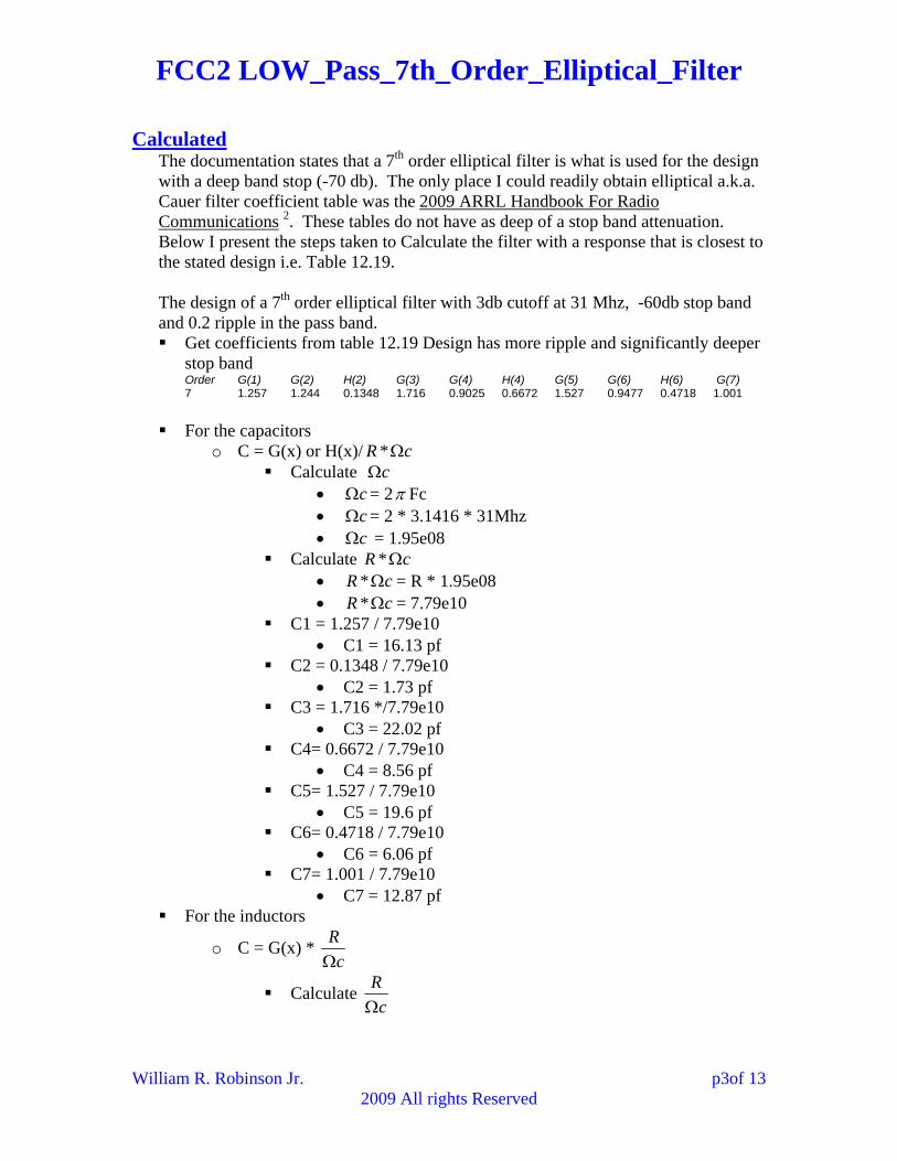
Calculated The documentation states that a 7th order elliptical filter is what is used for the design with a deep band stop (-70 db). The only place I could readily obtain elliptical a.k.a. Cauer filter coefficient table was the 2009 ARRL Handbook For Radio Communications 2. These tables do not have as deep of a stop band attenuation. Below I present the steps taken to Calculate the filter with a response that is closest to the stated design i.e. Table 12.19. The design of a 7th order elliptical filter with 3db cutoff at 31 Mhz, -60db stop band and 0.2 ripple in the pass band. Get coefficients from table 12.19 Design has more ripple and significantly deeper
stop band Order G(1) G(2) H(2) G(3) G(4) H(4) G(5) G(6) H(6) G(7) 7 1.257 1.244 0.1348 1.716 0.9025 0.6672 1.527 0.9477 0.4718 1.001
For the capacitors
o C = G(x) or H(x)/ cR * Calculate c
c = 2 Fc c = 2 * 3.1416 * 31Mhz c = 1.95e08
Calculate cR * cR * = R * 1.95e08 cR * = 7.79e10
C1 = 1.257 / 7.79e10 C1 = 16.13 pf
C2 = 0.1348 / 7.79e10 C2 = 1.73 pf
C3 = 1.716 */7.79e10 C3 = 22.02 pf
C4= 0.6672 / 7.79e10 C4 = 8.56 pf
C5= 1.527 / 7.79e10 C5 = 19.6 pf
C6= 0.4718 / 7.79e10 C6 = 6.06 pf
C7= 1.001 / 7.79e10 C7 = 12.87 pf
For the inductors
o C = G(x) * c
R
Calculate c
R
William R. Robinson Jr. p3of 13 2009 All rights Reserved
FCC2 LOW_Pass_7th_Order_Elliptical_Filter
c
R
= 400 / 1.95e08
c
R
= 2.05e-6
L1 = 1.244 * 2.05e-6 L1 = 2.55 uH
L2 = 0.9025 * 2.05e-6 L2 = 1.85 uH
L3 = 0.9477 * 2.05e-6 L3 = 1.95 uH
Frequency
The Cutoff frequency was chosen at 31 Mhz when the filter components were calculated. o Fc = 31 Mhz
Ripple
The ripple was chosen at 0.2 when the coefficients were chosen. o Ripple = 0.2 db
Stop Band Attenuation
The Stop band Attenuation was chosen at – 60 db when the coefficients were chosen. o Stop Band Attenuation = -60 db
Fstop Frequency
The Fstop frequency (1st frequency that meets the stop band attenuation) was chosen when the coefficients were chosen. o Fstop = Fc * 1.269
Fstop = 31 Mhz * 1.269 Fstop = 39.34 Mhz
Insertion Loss
“If inductors and capacitors were perfect and contained no internal resistive losses, then insertion loss for LC … filters would not exist.3 o Insertion Loss = 0 dB
William R. Robinson Jr. p4of 13 2009 All rights Reserved
FCC2 LOW_Pass_7th_Order_Elliptical_Filter
Simulation
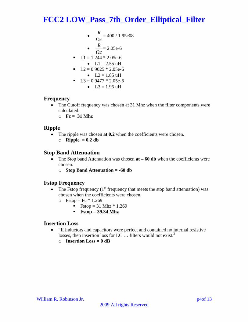
I simulated both the circuit used in the FCC2 and my nearest approximation. Frequency
FCC2 Design o Fc = 34.86 Mhz
My Closest Approximation
o Fc = 31.3 Mhz
Ripple FCC2 Design
o Ripple = 1.92 – -0.05 o Ripple = 1.97 db
My Closest Approximation o Ripple = 2.37 – -0.05 o Ripple = 2.42 db
VDB(in)VDB(out)VDB(out1)
Low_Pass_7th_Order_Elliptical_Filter-Small Signal AC-13-Graph
Frequency30.000M20.000M10.000M
3.5003.0002.5002.0001.5001.000
500.000m0.0
-500.000m-1.000-1.500-2.000-2.500-3.000-3.500-4.000-4.500-5.000-5.500-6.000-6.500-7.000-7.500-8.000-8.500
Stop Band Attenuation FCC2 Design
o Stop Band Attenuation = -56.7 db My Closest Approximation
o Stop Band Attenuation = -46.3 db
William R. Robinson Jr. p5of 13 2009 All rights Reserved
FCC2 LOW_Pass_7th_Order_Elliptical_Filter
VDB(in)VDB(out)VDB(out1)
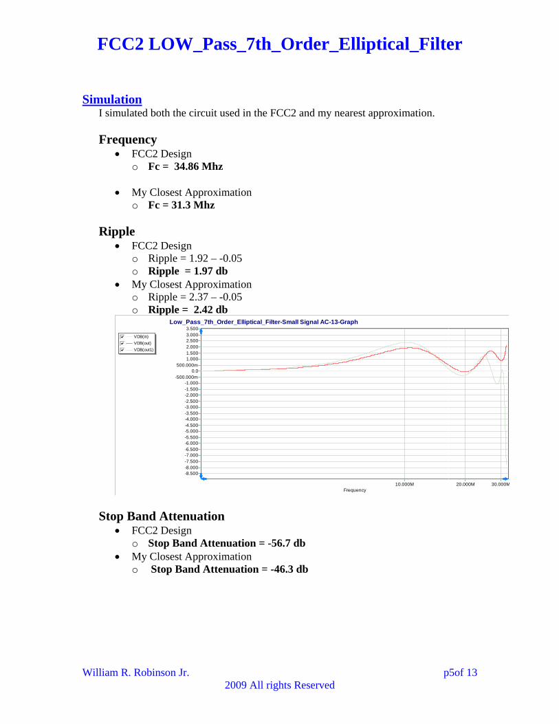
Low_Pass_7th_Order_Elliptical_Filter-Small Signal AC-14-Graph
Frequency100.000M 1.000G 10.000
20.000
10.000
0.0
-10.000
-20.000
-30.000
-40.000
-50.000
-60.000
-70.000
-80.000
-90.000
-100.000
-110.000
-120.000
-130.000
-140.000
-150.000
-160.000
Fstop Frequency
FCC2 Design o Fstop = -48.51 Mhz
My Closest Approximation o Fstop = -39.22 Mhz
VDB(in)VDB(out)VDB(out1)
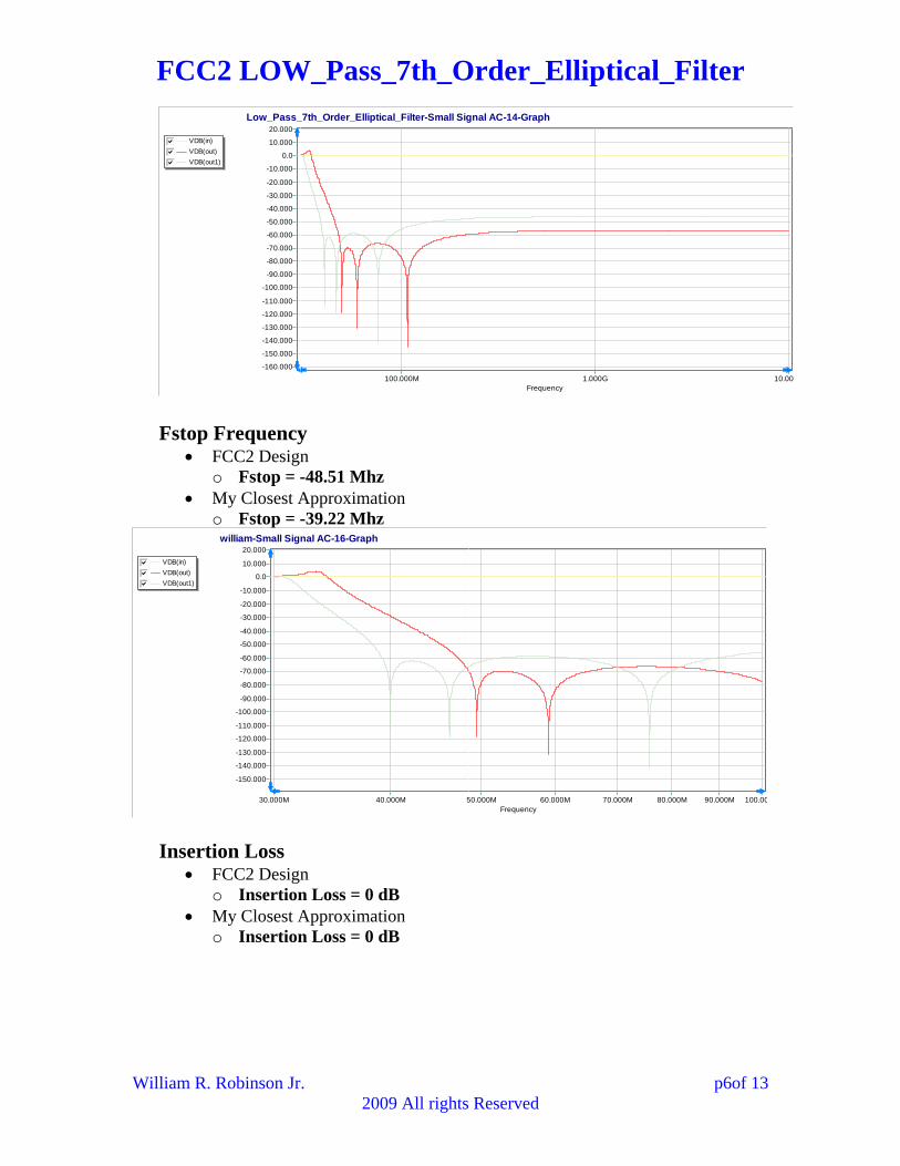
william-Small Signal AC-16-Graph
Frequency100.0090.000M80.000M70.000M60.000M50.000M40.000M30.000M
20.000
10.000
0.0
-10.000
-20.000
-30.000
-40.000
-50.000
-60.000
-70.000
-80.000
-90.000
-100.000
-110.000
-120.000
-130.000
-140.000
-150.000
Insertion Loss FCC2 Design
o Insertion Loss = 0 dB My Closest Approximation
o Insertion Loss = 0 dB
William R. Robinson Jr. p6of 13 2009 All rights Reserved
FCC2 LOW_Pass_7th_Order_Elliptical_Filter Real Circuit The filter measures very poorly compared to the simulations, showing large ripple that passes through the three db region twice.
Frequency
Fc = 25.5 Mhz o But another – 3db at 15.9 Mhz
Ripple Ripple = 2.22 – -3.85
o Ripple = 6.07 db
Stop Band Attenuation Unable to measure as I was using the FCC2 DDS and the source and it dos not
go past 30 Mhz
Fstop Frequency Unable to measure as I was using the FCC2 DDS and the source and it dos not
go past 30 Mhz
Insertion Loss Insertion Loss = 0 dB
William R. Robinson Jr. p7of 13 2009 All rights Reserved
FCC2 LOW_Pass_7th_Order_Elliptical_Filter
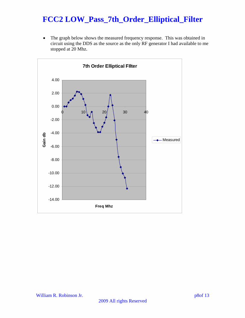
The graph below shows the measured frequency response. This was obtained in circuit using the DDS as the source as the only RF generator I had available to me stopped at 20 Mhz.
7th Order Elliptical FIlter
-14.00
-12.00
-10.00
-8.00
-6.00
-4.00
-2.00
0.00
2.00
4.00
0 10 20 30 40
Freq Mhz
Gai
n d
b
Measured
William R. Robinson Jr. p8of 13 2009 All rights Reserved
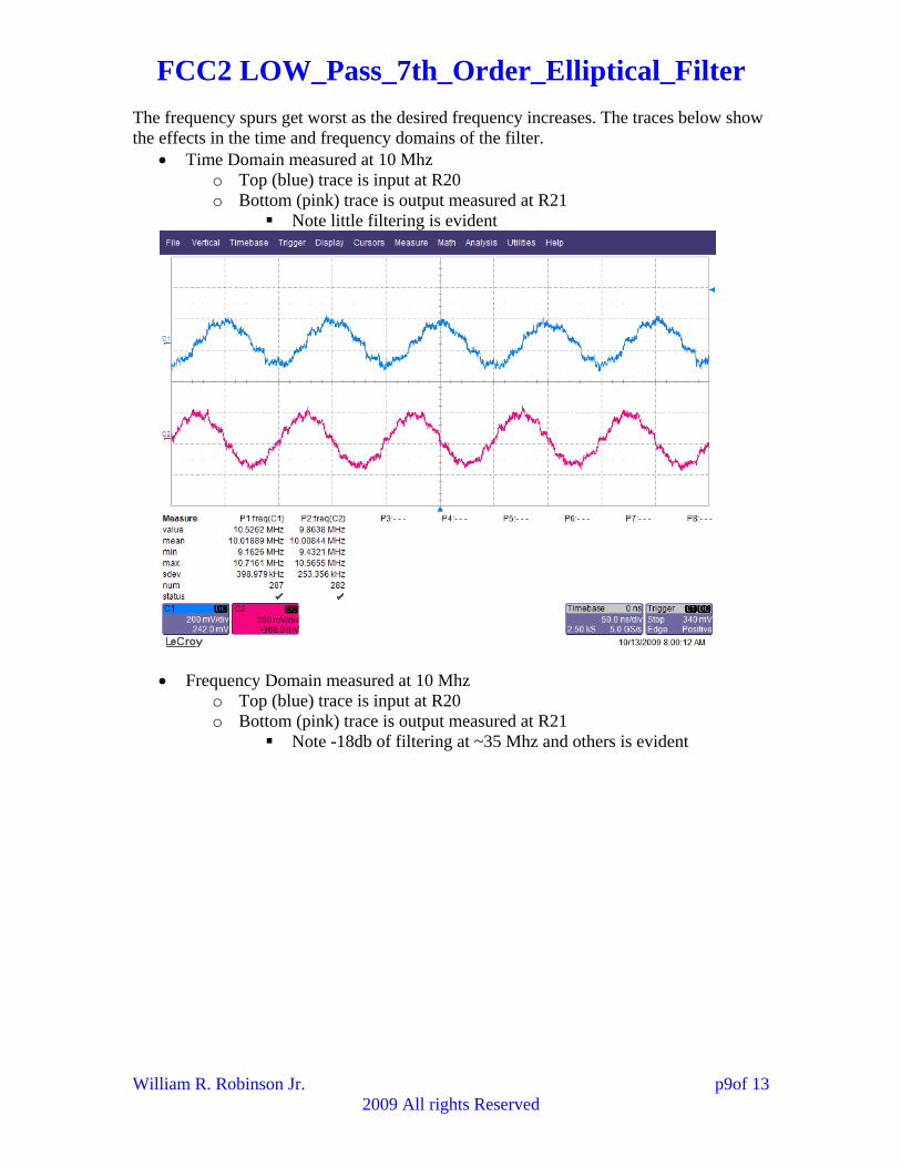
FCC2 LOW_Pass_7th_Order_Elliptical_Filter The frequency spurs get worst as the desired frequency increases. The traces below show the effects in the time and frequency domains of the filter.
Time Domain measured at 10 Mhz o Top (blue) trace is input at R20 o Bottom (pink) trace is output measured at R21
Note little filtering is evident
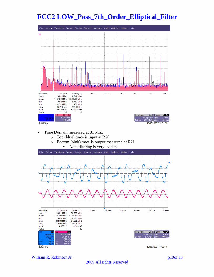
Frequency Domain measured at 10 Mhz o Top (blue) trace is input at R20 o Bottom (pink) trace is output measured at R21
Note -18db of filtering at ~35 Mhz and others is evident
William R. Robinson Jr. p9of 13 2009 All rights Reserved
FCC2 LOW_Pass_7th_Order_Elliptical_Filter
Time Domain measured at 31 Mhz o Top (blue) trace is input at R20 o Bottom (pink) trace is output measured at R21
Note filtering is very evident
William R. Robinson Jr. p10of 13 2009 All rights Reserved
FCC2 LOW_Pass_7th_Order_Elliptical_Filter
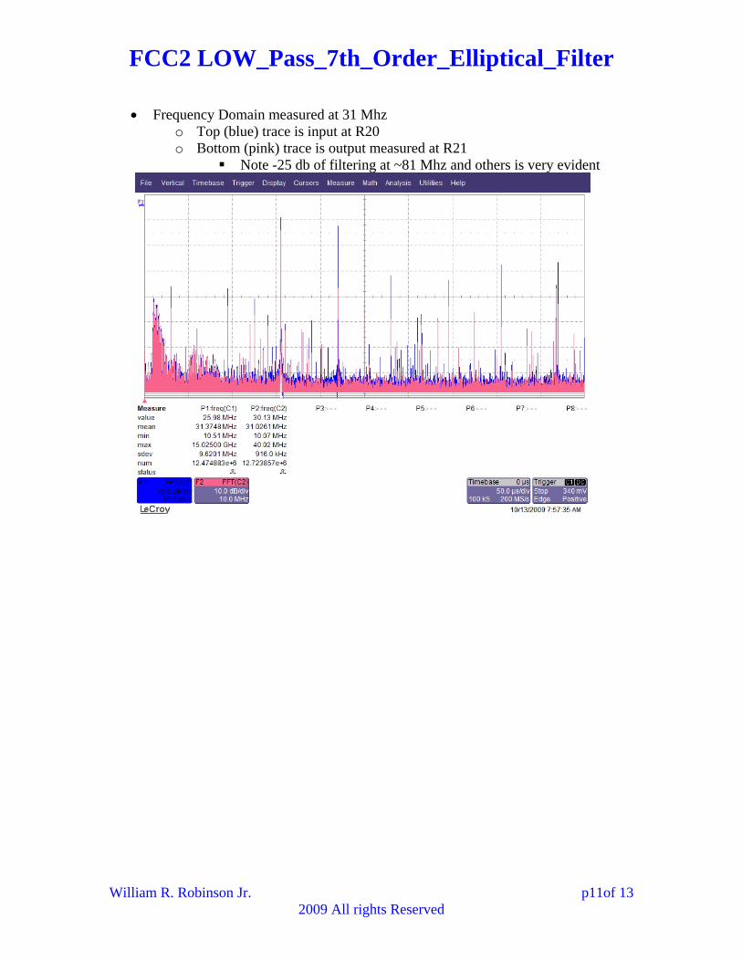
Frequency Domain measured at 31 Mhz
o Top (blue) trace is input at R20 o Bottom (pink) trace is output measured at R21
Note -25 db of filtering at ~81 Mhz and others is very evident
William R. Robinson Jr. p11of 13 2009 All rights Reserved

FCC2 LOW_Pass_7th_Order_Elliptical_Filter
Comparison The real circuit did not measure to far from the simulation and calculations
o One cause may be that the design tables used do not go to as deep of ripple
Real-Measured
SimulationApprox.
SimulationFCC2
Design
Calculated Documentation
Fc MHz 25.5 31.3 34.86 31 31Ripple db 6.07 2.02 1.97 0.2 N/AStop Bandwidth Attenuation db
N/A -46.3 -56.7 -60 N/A
Fstop Mhz N/A -39.22 -48.51 39.34 Insertion Loss db
0 0 0 0 N/A
The graph below shows a comparison of the frequency responses.
o The measured frequency response shows the same general trends
-14.00
-12.00
-10.00
-8.00
-6.00
-4.00
-2.00
0.00
2.00
4.00
0 10 20 30 40
Measured
Sim FCC2 Design
Sim Approximation
William R. Robinson Jr. p12of 13 2009 All rights Reserved
FCC2 LOW_Pass_7th_Order_Elliptical_Filter
William R. Robinson Jr. p13of 13 2009 All rights Reserved
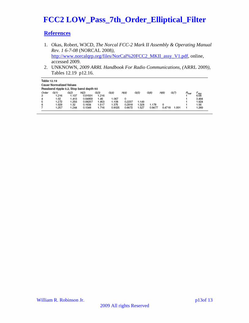
References
1. Okas, Robert, W3CD, The Norcal FCC-2 Mark II Assembly & Operating Manual Rev. 1 6-7-08 (NORCAL 2008), http://www.norcalqrp.org/files/NorCal%20FCC2_MKII_assy_V1.pdf, online, accessed 2009.
2. UNKNOWN, 2009 ARRL Handbook For Radio Communications, (ARRL 2009), Tables 12.19 p12.16.

![Resonance Damping and Parameter Design Method for LCL-LC ... · The filter can be of different types [6]. Compared with the first order L filter, the third-order LCL filter can meet](https://img.pdfslide.us/doc/110x75/5e76b9e50c589625166846e9/resonance-damping-and-parameter-design-method-for-lcl-lc-the-filter-can-be-of.jpg)


![LTC1065 5th Order Bessel LP Filter[18]](https://img.pdfslide.us/doc/110x75/577d298e1a28ab4e1ea72497/ltc1065-5th-order-bessel-lp-filter18.jpg)