Embed Size (px)
Citation preview
GOVERNMENT OF NEWFOUNDLAND AND LABRADORDEPARTMENT OF ENVIRONMENT AND LABOUR
WATER RESOURCES MANAGEMENT DIVISIONWater Investigations Section
CHAPTER 5Environmental Guidelines for
CULVERTS
Chapter 5
Environmental Guidelines For
CULVERTS
Water Resources Management DivisionWater Investigations Section
February 20, 1992
5.0 CULVERTS
- i -
Table of Contents
Page
List of Tables . . . . . . . . . . . . . . . . . . . . . . . . . . . . . . . . . . . . . . . . . . . . . . . . . . . . . . . iii
List of Figures . . . . . . . . . . . . . . . . . . . . . . . . . . . . . . . . . . . . . . . . . . . . . . . . . . . . . . iii
5.l General . . . . . . . . . . . . . . . . . . . . . . . . . . . . . . . . . . . . . . . . . . . . . . . . . . . . . . . 1
5.2 Culvert Location and Shape . . . . . . . . . . . . . . . . . . . . . . . . . . . . . . . . . . . . . . . . 2
5.2.1 Select a Stable Location . . . . . . . . . . . . . . . . . . . . . . . . . . . . . . . . . . . . . 25.2.2 Select a Site With Uniform Channel Gradient . . . . . . . . . . . . . . . . . . . . . 35.2.3 Location With Regard to Ice . . . . . . . . . . . . . . . . . . . . . . . . . . . . . . . . . 35.2.4 Culvert Shape . . . . . . . . . . . . . . . . . . . . . . . . . . . . . . . . . . . . . . . . . . . . . 3
5.3 Culvert Capacity . . . . . . . . . . . . . . . . . . . . . . . . . . . . . . . . . . . . . . . . . . . . . . . . 4
5.3.1 Provide Adequate Capacity to Prevent Surcharge . . . . . . . . . . . . . . . . . . 55.3.2 Allowance for Limited Gravel Deposition. . . . . . . . . . . . . . . . . . . . . . . . 75.3.3 Maintain Natural Stream Channel Capacity . . . . . . . . . . . . . . . . . . . . . . . 95.3.4 Debris Control Structures and Culvert Capacity
Should Address Maintenance Requirements . . . . . . . . . . . . . . . . . . . . . . 95.3.5 Anticipate Reduced Capacity . . . . . . . . . . . . . . . . . . . . . . . . . . . . . . . . . 9
5.4 Flow Velocities in Culverts . . . . . . . . . . . . . . . . . . . . . . . . . . . . . . . . . . . . . . . . 9
5.4.1 Choose Design Velocities to Suit Existing Flow Conditions . . . . . . . . . . 95.4.2 Results of High Velocity . . . . . . . . . . . . . . . . . . . . . . . . . . . . . . . . . . . . 105.4.3 Choose Correct Gradient . . . . . . . . . . . . . . . . . . . . . . . . . . . . . . . . . . . 10
5.5 Culvert Installation and Construction Practices . . . . . . . . . . . . . . . . . . . . . . . . . 11
5.5.1 Installation to Manufacturer's Specifications . . . . . . . . . . . . . . . . . . . . . 125.5.2 Operation of Heavy Equipment . . . . . . . . . . . . . . . . . . . . . . . . . . . . . . . 125.5.3 Work During Times of Low Flow . . . . . . . . . . . . . . . . . . . . . . . . . . . . . 125.5.4 Avoid In-Stream Excavation, Work in the Dry . . . . . . . . . . . . . . . . . . . 125.5.5 Control of Stream Flow for Culvert Placement. . . . . . . . . . . . . . . . . . . 12
5.0 CULVERTS
- ii -
5.5.6 Culvert Gradient to Follow Stream Gradient . . . . . . . . . . . . . . . . . . . . . 135.5.7 Multiple Culvert Installations . . . . . . . . . . . . . . . . . . . . . . . . . . . . . . . . 135.5.8 Place Culvert at Correct Elevation. . . . . . . . . . . . . . . . . . . . . . . . . . . . 135.5.9 Quality of Bedding and Backfill Material for Culverts. . . . . . . . . . . . . . 135.5.10 Procedure for Backfilling Culverts. . . . . . . . . . . . . . . . . . . . . . . . . . . . 135.5.11 Removal of Shipping Supports. . . . . . . . . . . . . . . . . . . . . . . . . . . . . . . 14
5.6 Culvert Inlet and Outlet Structures . . . . . . . . . . . . . . . . . . . . . . . . . . . . . . . . . . 14
5.6.1 Headwalls Required . . . . . . . . . . . . . . . . . . . . . . . . . . . . . . . . . . . . . . . 155.6.2 Use of Armour Rock . . . . . . . . . . . . . . . . . . . . . . . . . . . . . . . . . . . . . . 155.6.3 Use of Slope-Tapered Inlets . . . . . . . . . . . . . . . . . . . . . . . . . . . . . . . . . 165.6.4 Use of Steel End Sections . . . . . . . . . . . . . . . . . . . . . . . . . . . . . . . . . . . 165.6.5 Use of Concrete . . . . . . . . . . . . . . . . . . . . . . . . . . . . . . . . . . . . . . . . . . 165.6.6 Trash Racks Should be Sloped . . . . . . . . . . . . . . . . . . . . . . . . . . . . . . . 165.6.7 Use of Spill Aprons for Scour Protection. . . . . . . . . . . . . . . . . . . . . . . 16
5.7 Inspection and Maintenance . . . . . . . . . . . . . . . . . . . . . . . . . . . . . . . . . . . . . . . 17
5.7.1 Inspect Culverts Regularly . . . . . . . . . . . . . . . . . . . . . . . . . . . . . . . . . . 175.7.2 Inspect Culverts During and After Major Floods . . . . . . . . . . . . . . . . . . 175.7.3 Establish a Culvert Maintenance Program . . . . . . . . . . . . . . . . . . . . . . . 175.7.4 Mark Culvert Inlets and Outlets for Identification . . . . . . . . . . . . . . . . . 175.7.5 Protect Inlets and Outlets . . . . . . . . . . . . . . . . . . . . . . . . . . . . . . . . . . . 175.7.6 Replace Damaged Culverts. . . . . . . . . . . . . . . . . . . . . . . . . . . . . . . . . . 175.7.7 Maintenance Access. . . . . . . . . . . . . . . . . . . . . . . . . . . . . . . . . . . . . . . 18
5.0 CULVERTS
- iii -
List of Tables
Page
5.1 Transport velocity for various sizes of streambed materials . . . . . . . . . . . . . . . . 10
List of Figures
5.1 Common Shapes for Corrugated Steel Culverts . . . . . . . . . . . . . . . . . . . . . . . . . 45.2 California Balanced Design Method . . . . . . . . . . . . . . . . . . . . . . . . . . . . . . . . . . 65.3 Countersunk Culvert . . . . . . . . . . . . . . . . . . . . . . . . . . . . . . . . . . . . . . . . . . . . . 75.4 Conversion of Normal Round Culvert to Countersink Size . . . . . . . . . . . . . . . . . 85.5 Poorly Installed Culverts . . . . . . . . . . . . . . . . . . . . . . . . . . . . . . . . . . . . . . . . . 115.6 Pipe Arch Culvert with Masonry Headwall and Wingwalls . . . . . . . . . . . . . . . . 15
5.0 CULVERTS
- 1 -
5.l General
Culverts are often used to provide access across drainage ditches, intermittent streamsand small watercourses. Culverts can provide an efficient and inexpensive means ofcrossing provided they are properly designed and properly installed at suitablelocations. Often culverts are also necessary to provide drainage where roads or otherstructures would interfere with the otherwise normal flow of surface runoff.Temporary or permanent culvert stream crossings are preferred to fording of smallwatercourses where extensive fording may give rise to channel destabilization.
On some streams it is environmentally desirable to construct bridges instead of culvertcrossings because bridge installations can avoid extensive alteration of the flowregime which is inherent with most culvert installations. Bridges are also preferredto culverts in crossing all streams which support fish populations. Culvertinstallations usually result in more substantial alteration, or loss of sections of thenatural channel bed and can cause a partial or total barrier to fish migration.Installation of culverts in major watercourses and rivers, instead of bridges, is notconsidered a good environmental practice.
Many types of culverts are available from suppliers, the most popular beingcorrugated steel pipe. Reinforced concrete culverts, and plastic pipe culverts, areusually available in round sections only. Corrugated steel culverts are available in alarge variety of cross sectional shapes and sizes to suit varying stream conditions orrequirements, the most popular shape being round or arched.
All culvert installations of significant size, including multiple or gang culvertinstallation, should undergo thorough hydraulic and hydrologic analysis. Factors suchas channel gradient, flow velocity, channel cross section, channel roughness, dischargepatterns, peak water levels, quantity of flow and ice formation must be considered.
The completed culvert installation should safely accommodate reasonably predictablelevels of flow and adequately resist the erosive action of moving water withoutcreating any adverse environmental impact at the crossing or in upstream ordownstream areas. Flow quantity may be predicted through a variety of methodsincluding the rational method, unit hydrograph, SCS Method, or Regional FloodFrequency Analysis. In addition to utilizing any of these methods a relevant amountof data must be collected on the stream and its watershed such as:
- historical streamflows- velocity distribution in stream- high water marks- ice shove marks
5.0 CULVERTS
- 2 -
- precipitation data- potential river scour data- ice formation and ice jamming areas- rating of erosion hazard- surface drainage patterns- floodplains- surface area of rivers, lakes, bays, wetlands
While it is not always necessary or possible to determine all of the source data listedabove it is generally advisable to have sufficient data to check expected flood flow byat least two independent methods.
The following sections of this chapter provide helpful information for culvert designand installation to ensure that the width and depth of flow expected in the streamunder natural conditions is not significantly altered by the installation of culverts.Construction procedures should follow these guidelines with the primary objectivebeing to prevent environmental damage such as pollution and siltation. Theseguidelines are intended to provide explanatory information and guiding principles butdo not provide a complete code for design because certain design criteria such as loadbearing capacity should be derived from appropriate texts. Engineering advice shouldbe sought by lay people who wish to purchase and install their own culverts.
5.2 Culvert Location and Shape
The location of culverts is perhaps the most important consideration in installing anenvironmentally satisfactory culvert crossing. While the location of the road willprobably be the primary consideration, it is important to realize that minor changesin road alignment may be necessary to avoid problem areas as far as culvertinstallations are concerned.
5.2.1 Select a Stable LocationAvoid locations where there are abrupt or short radius bends in the streamchannel and areas where erosion, undercutting, or fine soils are evident.These areas are often subject to greater erosive force which could createproblems for a culvert installation.
Heavy erosive action can lead to undercutting of the culvert and structuraldamage. In addition, these areas are often unstable and the channel may beshifting. If the stream bed is mobile it may eventually bypass the culvert,rendering the installation useless. Culvert crossings should be located onstraight, stable channel segments with no evidence of heavy erosive action.
5.0 CULVERTS
- 3 -
5.2.2 Select a Site With Uniform Channel GradientSelect a culvert site where the channel gradient is uniform for a distanceupstream and downstream in the channel. This will avoid areas where theremay be sudden increases in water velocity immediately upstream ordownstream of the installation. The gradient must be constant at the crossingitself. Culverts should never be installed with bends in them.
Steeper channel gradients result in higher flow velocity. This could mean thatthe installation would be subject to greater risk of erosion and washout causedby the momentum of water striking the culvert inlet area. Areas of lowgradient should therefore be given preference.
5.2.3 Location With Regard to IceA culvert should not be located where large quantities of solid sheet ice areformed upstream. During spring runoff such ice may break loose and blockthe culvert. Outlet areas of small pools or ponds should therefore not beculverted.
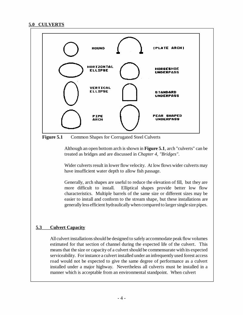
5.2.4 Culvert ShapeThe shape of a culvert should conform to the site conditions and to the flowregime at that location. While round culverts are the most popular, a varietyof shapes are available (see Figure 5.1). Design options are limited by flowcharacteristics and highway alignment. Where elevation is restricted thedesigner may select a shape which is horizontally elongated to produce thesame cross sectional area with less height.
5.0 CULVERTS
- 4 -
Figure 5.1 Common Shapes for Corrugated Steel Culverts
Although an open bottom arch is shown in Figure 5.1, arch "culverts" can betreated as bridges and are discussed in Chapter 4, "Bridges".
Wider culverts result in lower flow velocity. At low flows wider culverts mayhave insufficient water depth to allow fish passage.
Generally, arch shapes are useful to reduce the elevation of fill, but they aremore difficult to install. Elliptical shapes provide better low flowcharacteristics. Multiple barrels of the same size or different sizes may beeasier to install and conform to the stream shape, but these installations aregenerally less efficient hydraulically when compared to larger single size pipes.
5.3 Culvert Capacity
All culvert installations should be designed to safely accommodate peak flow volumesestimated for that section of channel during the expected life of the culvert. Thismeans that the size or capacity of a culvert should be commensurate with its expectedserviceability. For instance a culvert installed under an infrequently used forest accessroad would not be expected to give the same degree of performance as a culvertinstalled under a major highway. Nevertheless all culverts must be installed in amanner which is acceptable from an environmental standpoint. When culvert

5.0 CULVERTS
- 5 -
capacity is exceeded by a very large volume of flow or the capacity is reduced byblockage, there is a danger of:
- overtopping, damage to the roadway and traffic interruption- consequential threats to human safety- damage to adjacent property or the environment- unsafe outlet velocities- injurious deposition of bed load
Excessive headwater depth can contribute to a "piping effect" through the backfillmaterial surrounding culverts. This can undermine culverts and result in a majorwashout.
Surcharge conditions can cause flooding upstream of the culvert and/or scour anderosion at the culvert inlet.
5.3.1 Provide Adequate Capacity to Prevent SurchargeCulverts should be designed with adequate capacity to carry maximum designflows without creating surcharge or backwater conditions. In this regardculverts should be designed to carry the design flow with a headwater depthnot greater than the vertical dimension of the pipe. Large culverts (over 2.0m) should have a freeboard.
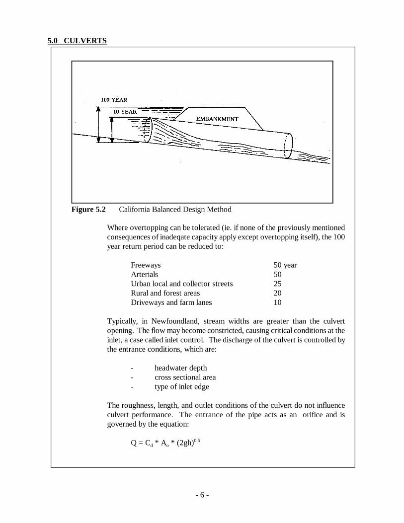
Small culverts under 2.0 m can use the California Balanced Design Method(see Figure 5.2), which specifies (1) a 10 year return flood can be carriedwithout static head at the inlet, and (2) a 100 year return flood will be carriedutilizing the full head available at the inlet.
5.0 CULVERTS
- 6 -
Figure 5.2 California Balanced Design Method
Where overtopping can be tolerated (ie. if none of the previously mentionedconsequences of inadeqate capacity apply except overtopping itself), the 100year return period can be reduced to:
Freeways 50 yearArterials 50Urban local and collector streets 25Rural and forest areas 20Driveways and farm lanes 10
Typically, in Newfoundland, stream widths are greater than the culvertopening. The flow may become constricted, causing critical conditions at theinlet, a case called inlet control. The discharge of the culvert is controlled bythe entrance conditions, which are:
- headwater depth- cross sectional area- type of inlet edge
The roughness, length, and outlet conditions of the culvert do not influenceculvert performance. The entrance of the pipe acts as an orifice and isgoverned by the equation:
Q = Cd * Ao * (2gh)0.5
5.0 CULVERTS
- 7 -
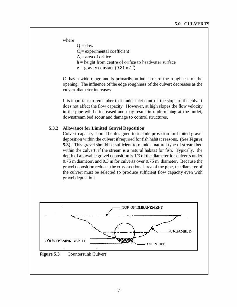
Figure 5.3 Countersunk Culvert
whereQ = flowCd= experimental coefficientAo= area of orificeh = height from centre of orifice to headwater surfaceg = gravity constant (9.81 m/s2)
Cd has a wide range and is primarily an indicator of the roughness of theopening. The influence of the edge roughness of the culvert decreases as theculvert diameter increases.
It is important to remember that under inlet control, the slope of the culvertdoes not affect the flow capacity. However, at high slopes the flow velocityin the pipe will be increased and may result in undermining at the outlet,downstream bed scour and damage to control structures.
5.3.2 Allowance for Limited Gravel DepositionCulvert capacity should be designed to include provision for limited graveldeposition within the culvert if required for fish habitat reasons. (See Figure5.3). This gravel should be sufficient to mimic a natural type of stream bedwithin the culvert, if the stream is a natural habitat for fish. Typically, thedepth of allowable gravel deposition is 1/3 of the diameter for culverts under0.75 m diameter, and 0.3 m for culverts over 0.75 m diameter. Because thegravel deposition reduces the cross sectional area of the pipe, the diameter ofthe culvert must be selected to produce sufficient flow capacity even withgravel deposition.
5.0 CULVERTS
- 8 -
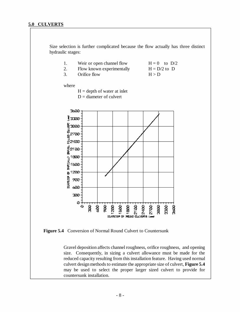
Figure 5.4 Conversion of Normal Round Culvert to Countersunk
Size selection is further complicated because the flow actually has three distincthydraulic stages:
1. Weir or open channel flow H = 0 to D/22. Flow known experimentally H = D/2 to D3. Orifice flow H > D
whereH = depth of water at inletD = diameter of culvert
Gravel deposition affects channel roughness, orifice roughness, and openingsize. Consequently, in sizing a culvert allowance must be made for thereduced capacity resulting from this installation feature. Having used normalculvert design methods to estimate the appropriate size of culvert, Figure 5.4may be used to select the proper larger sized culvert to provide forcountersunk installation.
5.0 CULVERTS
- 9 -
5.3.3 Maintain Natural Stream Channel CapacityCulvert installations should provide capacity equivalent to that of the existingnatural channel. In this regard infilling of the channel or reduction of thenatural cross sectional area of the channel due to the culvert placement andbackfilling should be avoided. Pipe arches are a preferred shape over circularpipe in wide and flat bottomed streams.
5.3.4 Debris Control Structures and Culvert Capacity Should AddressMaintenance RequirementsMany debris barriers or trash racks require cleaning after every storm. Theexpected frequency of debris removal should be considered in selecting thedebris control structure. If a low standard of maintenance is anticipated, thedesigner should choose to pass the debris through the structure by ensuringadequate capacity.
5.3.5 Anticipate Reduced CapacityWhereas the design capacity for a culvert installation may indicate an adequateinstallation purely from a hydrologic point of view, the possibility of reducedcapacity must be anticipated. This is particularly important where there is ice,debris from logging or other forestry operations or debris from vandalism andlittering. A culvert may require dramatic over sizing to allow passage ofdebris.
5.4 Flow Velocities in Culverts
5.4.1 Choose Design Velocities to Suit Existing Flow ConditionsThe design flow velocity in culverts should be chosen to conform withexisting natural upstream and downstream flow velocities. All factors whichdetermine flow velocity through a culvert should be examined. These include:
- The slope of the culvert (grade on which it is placed),- the roughness of the inside of the culvert,- the design of the culvert inlet and outlet,- the flow volume,- the level or head of water at the inlet,- backwater effects from downstream controls, and,- the culvert type or more specifically the cross sectional shape which
determines the perimeter in contact with the flowing water.
5.0 CULVERTS
- 10 -
Low inlet and outlet flow velocities are preferred for all culvert installations. Highvelocity flow can result in undermining, erosion, and washouts of culverts and canalso create an impasse to migrating fish. The flow velocity at times of normal flowconditions should not exceed 0.9 m/s except in instances where very steep naturalchannel grade and high velocity flow in the channel dictate a high flow velocitythrough the culvert.
5.4.2 Results of High VelocitiesThe downstream results of higher velocities may involve:
- bed scour- bank erosion- structural damage or overtopping of control structures- undercutting of culvert.
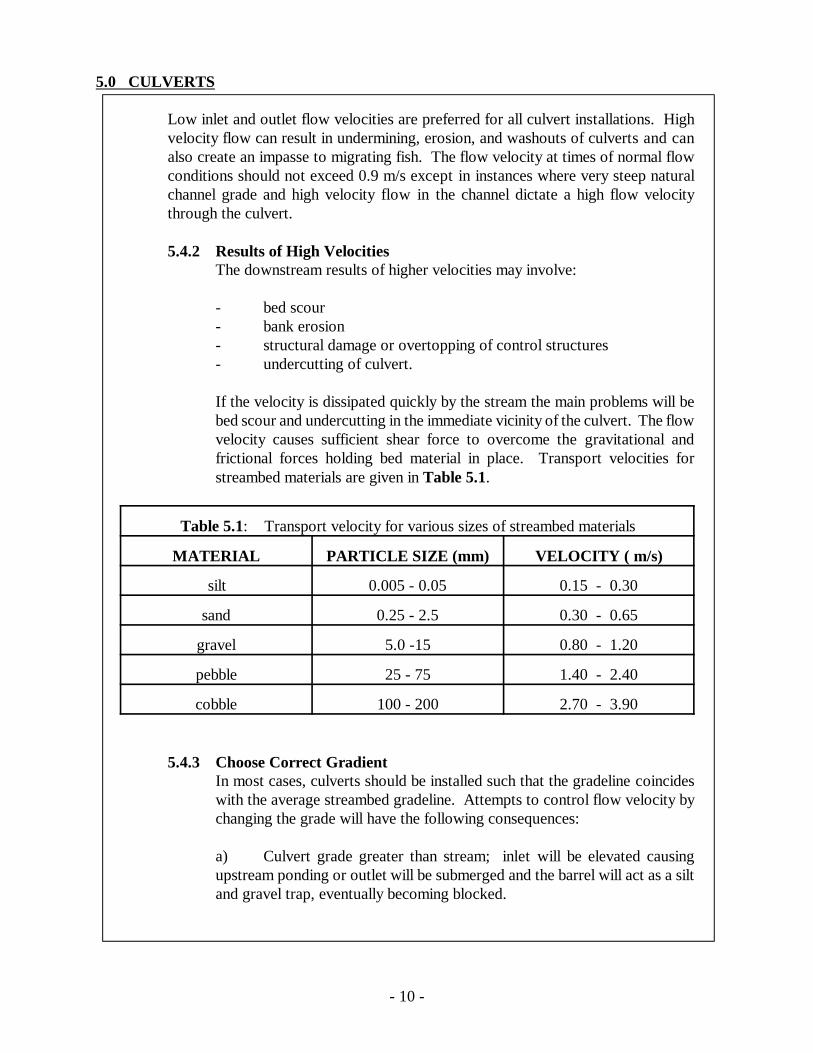
If the velocity is dissipated quickly by the stream the main problems will bebed scour and undercutting in the immediate vicinity of the culvert. The flowvelocity causes sufficient shear force to overcome the gravitational andfrictional forces holding bed material in place. Transport velocities forstreambed materials are given in Table 5.1.
Table 5.1: Transport velocity for various sizes of streambed materials
MATERIAL PARTICLE SIZE (mm) VELOCITY ( m/s)
silt 0.005 - 0.05 0.15 - 0.30
sand 0.25 - 2.5 0.30 - 0.65
gravel 5.0 -15 0.80 - 1.20
pebble 25 - 75 1.40 - 2.40
cobble 100 - 200 2.70 - 3.90
5.4.3 Choose Correct GradientIn most cases, culverts should be installed such that the gradeline coincideswith the average streambed gradeline. Attempts to control flow velocity bychanging the grade will have the following consequences:
a) Culvert grade greater than stream; inlet will be elevated causingupstream ponding or outlet will be submerged and the barrel will act as a siltand gravel trap, eventually becoming blocked.
5.0 CULVERTS
- 11 -
Figure 5.5 Poorly Installed Culverts
b) Culvert grade less than stream; inlet will have a drop or outlet will behanging.
Both cases will act as an obstruction for fish passage.
While some deviation from the stream grade may serve to decrease flowvelocity in a culvert, calculations justifying this deviation must be performed.If the desired flow velocity cannot be achieved this way, then it is obviousthat a bridge, rather than a culvert, is required.
5.5 Culvert Installation and Construction Practices
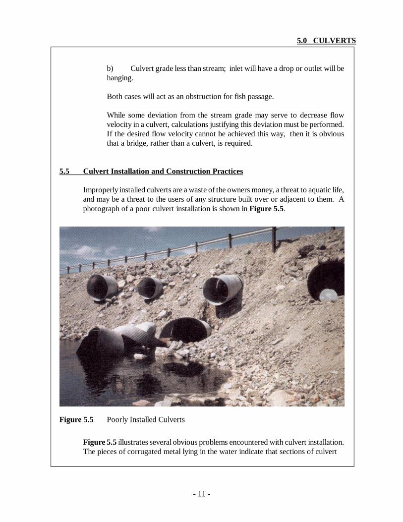
Improperly installed culverts are a waste of the owners money, a threat to aquatic life,and may be a threat to the users of any structure built over or adjacent to them. Aphotograph of a poor culvert installation is shown in Figure 5.5.
Figure 5.5 illustrates several obvious problems encountered with culvert installation.The pieces of corrugated metal lying in the water indicate that sections of culvert
5.0 CULVERTS
- 12 -
have failed under load and collapsed onto the stream bed. The culverts are projectingfrom the fill.
There is no end protection to resist erosive action. It appears that the culverts havebeen placed haphazardly with very little concern for hydraulics, aesthetics, fishpassage, or embankment protection. The embankment is poorly constructed andunstable.
Hopefully these guidelines will help installers avoid situations like the one picturedabove.
5.5.1 Installation to Manufacturer's SpecificationsThe installation of all culverts should comply with the specificationsprescribed by the manufacturer of that product, particularly in regard to pipezone bedding material quality, degree of compaction, and minimum ormaximum pipe cover for design loadings.
5.5.2 Operation of Heavy EquipmentThe use of heavy equipment in waterbodies should be avoided. The operationof heavy equipment should be confined to dry stable areas.
5.5.3 Work During Times of Low FlowAll work involving minor alterations to the stream channel to permit culvertplacement should be carried out at a time of low flow conditions. It isprudent however to be prepared for increased flows by scheduling workaccording to the weather forecast and to have a contingency plan forunexpectedly large runoff from a sudden storm.
5.5.4 Avoid In-Stream Excavation, Work in the DryIn-stream excavation can cause considerable siltation and pollution ofwatercourses. If excavation of bed material or other extensive in-stream workis necessary, to make a level bed for the culvert for example, all flow shouldbe diverted or confined to a section to allow the work to be carried out in thedry.
5.5.5 Control of Stream Flow for Culvert PlacementStreamflow may be controlled in any of a number of ways in order to providea dry working area. Four methods which may be used include the following:
l. A temporary diversion channel. (See Chapter 7, "Diversions, NewChannels, Major Stream Alterations").
2. A temporary culvert(s).
5.0 CULVERTS
- 13 -
3. Pumping. (See Chapter 13, "General Construction Practices").
4. Confining flow to a channel section by use of cofferdams. (SeeChapter 13, "General Construction Practices").
5.5.6 Culvert Gradient to Follow Stream GradientThe gradient of all culverts as far as possible should follow the stream channelgradient and should be placed in line with the direction of the main flow.
5.5.7 Multiple Culvert InstallationsIn multiple (gang) culvert installations, one culvert should be set at anelevation lower than the others to provide adequate flow depth and velocityfor fish passage during low flow conditions.
5.5.8 Place Culvert at Correct ElevationCulverts should be placed at such an elevation that there is no ponding ofwater at the upstream inlet of the culvert and there is drop or hydraulic jumpcreated at the outlet of the culvert. Similarly, outlets should not besubmerged.
Large culverts may be countersunk into the channel bed. This also permitssome gravel deposition in the culvert which creates a natural type of bedwithin the culvert.
5.5.9 Quality of Bedding and Backfill Material for CulvertsSuitable material of good quality should be used in backfilling culverts toensure a good culvert installation. A compactable granular material "GranularClass B" quality or better is suitable for most installations. Cohesive soils ormaterial containing large amounts of sand, fine silt or clay should not be used,because erosion of the material may result. Well graded granular material alsoprovides better load carrying capability than poorly graded material orcohesive soils. Small culverts may be backfilled with the same material usedto construct the road. Provided that the material meets road constructionstandards. Larger culverts should be backfilled more carefully, using selectmaterial if necessary.
5.5.10 Procedure for Backfilling CulvertsBackfill material placed under the haunches of the pipe should be in intimatecontact with the entire bottom surface of the structure. Pre-shaping thebedding material to match the culvert curvature may assist in this regard.Backfill material should be placed in layers not exceeding 300 mm in thicknessand compacted with suitable hand operated compacting equipment.Backfilling should be done in a manner that will prevent any deformation or
5.0 CULVERTS
- 14 -
displacement of the culvert. Proper compaction is necessary to provideadequate load bearing capacity above the culvert, and is necessary to reducethe voids which can cause "piping effect". The soil compaction around theculvert should achieve 90% standard Proctor density or better. The majorfactors which influence soil compaction and which should be taken intoconsideration include the following:
- moisture content of the soil,- nature of the soil, its gradation and physical properties,- type and amount of compaction effort required.
Granular soil types are best compacted by applying a continuous vibratoryaction.
5.5.11 Removal of Shipping SupportsLarge diameter culverts are often shipped with bracing to prevent deformationof the culvert during transport and installation. These braces should beremoved upon completion of the work as they may contribute to blockagesby debris or ice.
5.6 Culvert Inlet and Outlet Structures
Culvert end structures, pre-built or constructed in place are attached to the ends ofculverts to reduce erosion, retain the fill, inhibit seepage, improve the aesthetics andhydraulic characteristics and make the ends structurally stable.
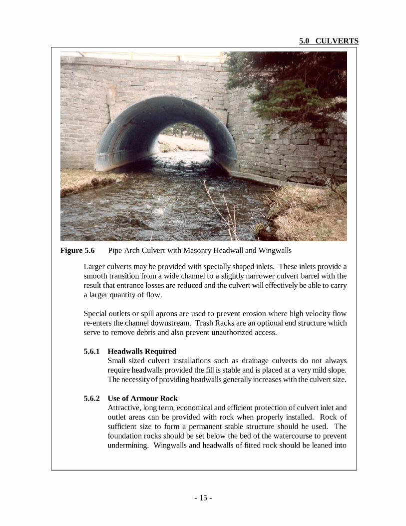
Headwalls may be made of concrete, lumber, steel sheet piling or rock either groutedor cemented or simply left plain. Headwalls are sometimes skewed relative to theculvert to fit the angle of crossing. Wingwalls may be used to aid in funnelling theapproaching flow of water directly into the inlet and to prevent erosion on the streambanks adjacent to the culvert. Figure 5.6 shows a masonry headwall and wingwalls
5.0 CULVERTS
- 15 -
Figure 5.6 Pipe Arch Culvert with Masonry Headwall and Wingwalls
Larger culverts may be provided with specially shaped inlets. These inlets provide asmooth transition from a wide channel to a slightly narrower culvert barrel with theresult that entrance losses are reduced and the culvert will effectively be able to carrya larger quantity of flow.
Special outlets or spill aprons are used to prevent erosion where high velocity flowre-enters the channel downstream. Trash Racks are an optional end structure whichserve to remove debris and also prevent unauthorized access.
5.6.1 Headwalls RequiredSmall sized culvert installations such as drainage culverts do not alwaysrequire headwalls provided the fill is stable and is placed at a very mild slope.The necessity of providing headwalls generally increases with the culvert size.
5.6.2 Use of Armour RockAttractive, long term, economical and efficient protection of culvert inlet andoutlet areas can be provided with rock when properly installed. Rock ofsufficient size to form a permanent stable structure should be used. Thefoundation rocks should be set below the bed of the watercourse to preventundermining. Wingwalls and headwalls of fitted rock should be leaned into
5.0 CULVERTS
- 16 -
the embankment at an inclination of at least 1/6 from the vertical axis toensure stability. Joints can be pointed with concrete or mortar to provide amore uniform or water tight surface but the structure should not be dependenton the jointing material for structural stability. Where irregular or rubble rockis used to protect inlet and outlet areas, the rock should form a slope nosteeper than one horizontal to one vertical and it should be well consolidated.
5.6.3 Use of Slope-Tapered InletsA tapered inlet slope provides less inlet head loss and thus can provide greatercapacity and efficiency for culverts installations. Projecting culvert ends canbe cut with a tapered slope to conform to the finished embankment slope andprovides a neater and more aesthetically pleasing installation. Slope taperedinlets also provide less likelihood of serious blockage of the inlet by debris.However, special measures must be employed to prevent uplift of theprojecting lip.
5.6.4 Use of Steel End SectionsA variety of steel end sections which are shop fabricated for assembly in thefield, are available for attachment to corrugated steel pipe. These can providebetter hydraulic inlet and outlet conditions and protection from erosion orscour of the road embankment and bed material, and can provide protectionto the culvert ends as well.
5.6.5 Use of ConcreteHeadwalls, wingwalls, spill aprons or other end structures constructed of castin place concrete should be installed in accordance with the guidelines on useof concrete in Chapter 13, "General Construction Practices".
5.6.6 Trash Racks Should be SlopedWhere a trash rack is used to catch debris and prevent it from entering aculvert, the rack should be installed with a low incline to prevent floatingdebris from being held against the rack by the flow (as with vertical trashracks) as this can cause serious flow constriction flooding, or washouts. Aninclined rack allows debris to be pushed up to the top of the inlet structurewhere it will not seriously constrict flow and where it can be easily removed.
5.6.7 Use of Spill Aprons for Scour ProtectionAn apron of fitted rock, or rip-rap can be installed at the outlet of a culvert toprovide protection to the stream bed and prevent scour or undermining. Sucha structure can also provide a sufficient roughness factor to reduce thevelocity at the outlet thus providing further protection from erosion or scour.
5.0 CULVERTS
- 17 -
This is preferred to concrete or steel aprons which do not significantly reduceoutlet velocities and which often cause scour of the bed material at the apronlip.
5.7 Inspection and Maintenance
5.7.1 Inspect Culverts RegularlyCulvert installations should be inspected regularly so that immediate actioncan be taken to clear blockages caused by ice or debris and to identify anyapparent problems, such as erosion, which may require remedial action.
5.7.2 Inspect Culverts During and After Major FloodsAn inspection of culverts should be made during and after major floods toobserve the culvert operation and record high water marks. Conditions whichrequire corrective maintenance should be noted including debrisaccumulations, silting, erosion, piping, scour, and structural damage.Performance information that reflects a need for design or constructionchanges due to unexpected large flood peaks should be submitted to theregulatory authority or owner for further action.
5.7.3 Establish a Culvert Maintenance ProgramCulvert failures can be both disastrous and expensive. A comprehensiveprogram for maintaining culverts in good repair and operating condition willreduce the probability of failures and prove to be cost effective. The programshould include periodic inspections with supplemental inspections followingflood events.
5.7.4 Mark Culvert Inlets and Outlets for IdentificationAll culvert inlets and outlets should be clearly marked so as to be identifiedduring snow clearing and road grading operations.
5.7.5 Protect Inlets and OutletsInlet and outlet areas of culvert installations must be adequately protected byplacing rip-rap, or fitted stone, or concrete headwalls to prevent bank hadchannel erosion.
5.7.6 Replace Damaged CulvertsCulverts which have been damaged by ice or debris, by improper installationor construction procedures, or are in a condition which could impair theirproper functioning should be replaced immediately to prevent overtopping,erosion, or flooding.
5.0 CULVERTS
- 18 -
5.7.7 Maintenance AccessProvisions for maintenance access are necessary especially where debriscontrol structures are installed. A parking area for equipment such as a cranemay be necessary in order to remove debris without disrupting traffic. Alsosuch access should not disrupt the site rehabilitation efforts.